Embed Size (px)
Citation preview
ENGINE MECHANICAL
SECTION EM
CONTENTSPRECAUTIONS ...............................................................3
Parts Requiring Angular Tightening.............................3Liquid Gasket Application Procedure ..........................3
PREPARATION ................................................................4Special Service Tools ..................................................4Commercial Service Tools ...........................................6
NOISE, VIBRATION AND HARSHNESS (NVH)TROUBLESHOOTING .....................................................8
NVH Troubleshooting Chart — Engine Noise .............9OUTER COMPONENT PARTS .....................................10COMPRESSION PRESSURE........................................12
Measurement of Compression Pressure...................12OIL PAN .........................................................................13
Removal.....................................................................13Installation..................................................................14
TIMING BELT.................................................................16Removal.....................................................................17Inspection...................................................................18
Belt Tensioner And Tensioner Spring....................19Installation..................................................................19Tension Adjustment....................................................20
After Belt Replacement .........................................20After Engine Overhaul Or Engine Reassembly(With Rocker Covers Removed) ...........................20
OIL SEAL REPLACEMENT ..........................................23Valve Oil Seal........................................................23Oil Seal Installing Direction...................................23Camshaft Oil Seal .................................................23Front Oil Seal ........................................................24Rear Oil Seal.........................................................24
CYLINDER HEAD..........................................................25Removal.....................................................................26Disassembly...............................................................28Inspection...................................................................29
Cylinder Head Distortion .......................................29Camshaft Visual Check.........................................29Camshaft Runout ..................................................29Camshaft Cam Height...........................................29Camshaft Journal Clearance ................................30Camshaft End Play ...............................................30
Camshaft Sprocket Runout...................................31Valve Guide Clearance .........................................31Valve Guide Replacement ....................................31Valve Seats ...........................................................32Replacing Valve Seat For Service Parts ..............32Valve Dimensions..................................................33Valve Spring ..........................................................33
Squareness.......................................................33Pressure ...........................................................33
Rocker Shaft And Rocker Arm..............................34Hydraulic Valve Lifter ............................................34
Assembly ...................................................................34Installation..................................................................35
ENGINE REMOVAL.......................................................39Front Engine Mounting..........................................39Rear Engine Mounting ..........................................40
Removal.....................................................................41CYLINDER BLOCK .......................................................42
Disassembly...............................................................43Piston And Crankshaft ..........................................43
Inspection...................................................................43Piston And Piston Pin Clearance..........................43Piston Ring Side Clearance..................................44Piston Ring End Gap ............................................44Connecting Rod Bend And Torsion.......................44Cylinder Block Distortion And Wear......................45Piston-To-Bore Clearance .....................................45Crankshaft .............................................................47Bearing Clearance ................................................47
Method A (Using bore gauge & micrometer) ...47Connecting rod bearing (Big end).........................49
Method B (Using plastigage)............................49Connecting Rod Bushing Clearance (Smallend) .......................................................................50Replacement of Connecting Rod Bushing(Small end)............................................................50Flywheel/Drive Plate Runout.................................50
Assembly ...................................................................50Piston ....................................................................50Crankshaft .............................................................51
GI
MA
EM
LC
EC
FE
CL
MT
AT
TF
PD
FA
RA
BR
ST
RS
BT
HA
EL
IDX
Replacing Pilot Bushing (M/T) Or PilotConverter (A/T) .....................................................52
SERVICE DATA AND SPECIFICATIONS (SDS) ..........53General Specifications...............................................53Inspection and Adjustment ........................................53
Cylinder Head .......................................................53Valve......................................................................54
Valve spring ......................................................54Hydraulic valve lifter .........................................54Valve guide .......................................................54Rocker shaft and rocker arm............................54Intake valve seat ..............................................55Exhaust valve seat ...........................................55
Camshaft And Camshaft Bearing .........................55Cylinder Block .......................................................56Cylinder Block .......................................................56
Connecting Rod ....................................................57Piston, Piston Ring And Piston Pin.......................57
Available piston.................................................57Available piston.................................................57Piston ring.........................................................57Piston pin..........................................................58
Crankshaft .............................................................58Available Main Bearing .........................................58No. 1 Main Bearing ...............................................58No. 2 And 3 Main Bearing ....................................58No. 4 Main Bearing ...............................................58Under Size ............................................................59Available Connecting Rod Bearing .......................59
Connecting rod bearing undersize ...................59Miscellaneous Components ..................................59
Bearing clearance.............................................59
CONTENTS (Cont’d.)
EM-2
Parts Requiring Angular Tightening● Use an angle wrench for the final tightening of the following
engine parts:(1) Cylinder head bolts(2) Main bearing cap bolts(3) Connecting rod cap nuts(4) Crankshaft pulley bolt
● Do not use a torque value for final tightening.● The torque value for these parts are for a preliminary step.● Ensure thread and seat surfaces are clean and coated with
engine oil.
SEM371C
AEM080
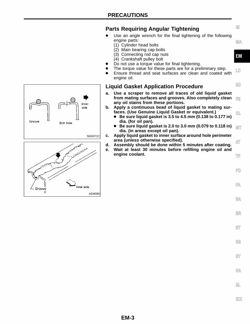
Liquid Gasket Application Procedurea. Use a scraper to remove all traces of old liquid gasket
from mating surfaces and grooves. Also completely cleanany oil stains from these portions.
b. Apply a continuous bead of liquid gasket to mating sur-faces. (Use Genuine Liquid Gasket or equivalent.)● Be sure liquid gasket is 3.5 to 4.5 mm (0.138 to 0.177 in)
dia. (for oil pan).● Be sure liquid gasket is 2.0 to 3.0 mm (0.079 to 0.118 in)
dia. (in areas except oil pan).c. Apply liquid gasket to inner surface around hole perimeter
area (unless otherwise specified).d. Assembly should be done within 5 minutes after coating.e. Wait at least 30 minutes before refilling engine oil and
engine coolant.
GI
MA
EM
LC
EC
FE
CL
MT
AT
TF
PD
FA
RA
BR
ST
RS
BT
HA
EL
IDX
PRECAUTIONS
EM-3
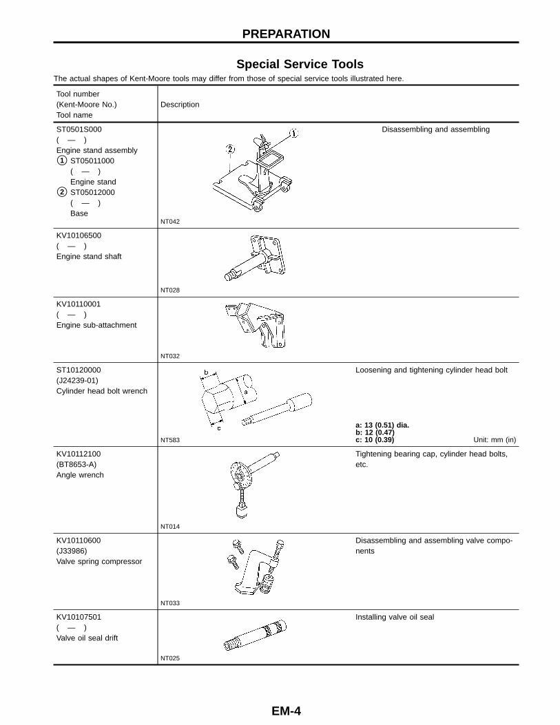
Special Service ToolsThe actual shapes of Kent-Moore tools may differ from those of special service tools illustrated here.
Tool number(Kent-Moore No.)Tool name
Description
ST0501S000( — )Engine stand assembly
�1 ST05011000( — )Engine stand
�2 ST05012000( — )Base
NT042
Disassembling and assembling
KV10106500( — )Engine stand shaft
NT028
KV10110001( — )Engine sub-attachment
NT032
ST10120000(J24239-01)Cylinder head bolt wrench
NT583
Loosening and tightening cylinder head bolt
a: 13 (0.51) dia.b: 12 (0.47)c: 10 (0.39) Unit: mm (in)
KV10112100(BT8653-A)Angle wrench
NT014
Tightening bearing cap, cylinder head bolts,etc.
KV10110600(J33986)Valve spring compressor
NT033
Disassembling and assembling valve compo-nents
KV10107501( — )Valve oil seal drift
NT025
Installing valve oil seal
PREPARATION
EM-4
Tool number(Kent-Moore No.)Tool name
Description
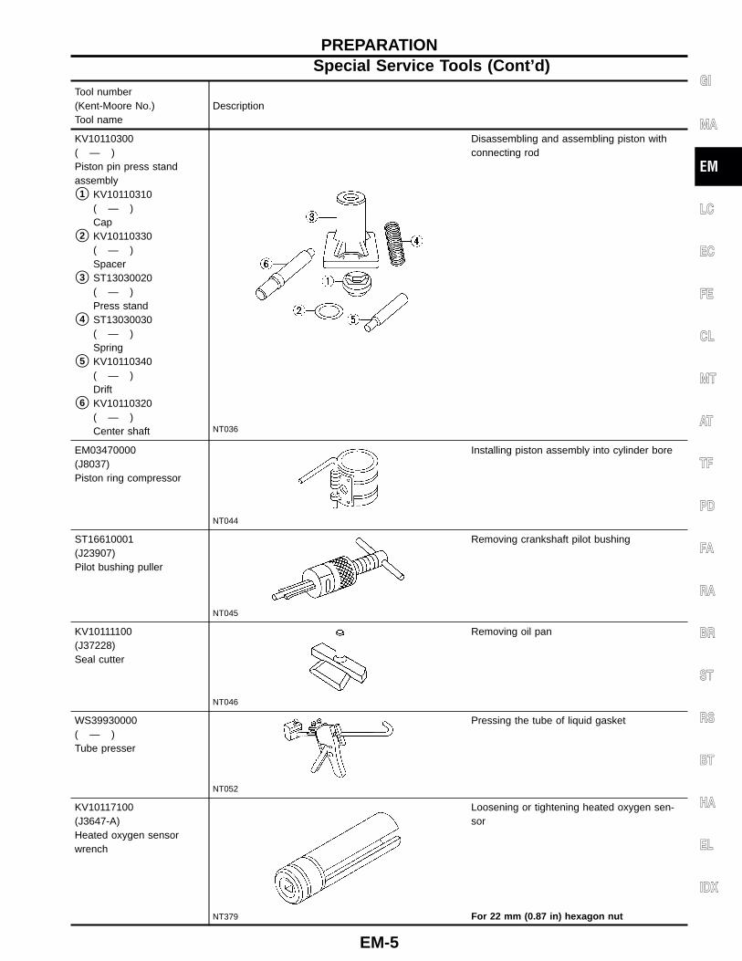
KV10110300( — )Piston pin press standassembly
�1 KV10110310( — )Cap
�2 KV10110330( — )Spacer
�3 ST13030020( — )Press stand
�4 ST13030030( — )Spring
�5 KV10110340( — )Drift
�6 KV10110320( — )Center shaft NT036
Disassembling and assembling piston withconnecting rod
EM03470000(J8037)Piston ring compressor
NT044
Installing piston assembly into cylinder bore
ST16610001(J23907)Pilot bushing puller
NT045
Removing crankshaft pilot bushing
KV10111100(J37228)Seal cutter
NT046
Removing oil pan
WS39930000( — )Tube presser
NT052
Pressing the tube of liquid gasket
KV10117100(J3647-A)Heated oxygen sensorwrench
NT379
Loosening or tightening heated oxygen sen-sor
For 22 mm (0.87 in) hexagon nut
GI
MA
EM
LC
EC
FE
CL
MT
AT
TF
PD
FA
RA
BR
ST
RS
BT
HA
EL
IDX
PREPARATIONSpecial Service Tools (Cont’d)
EM-5
Tool number(Kent-Moore No.)Tool name
Description
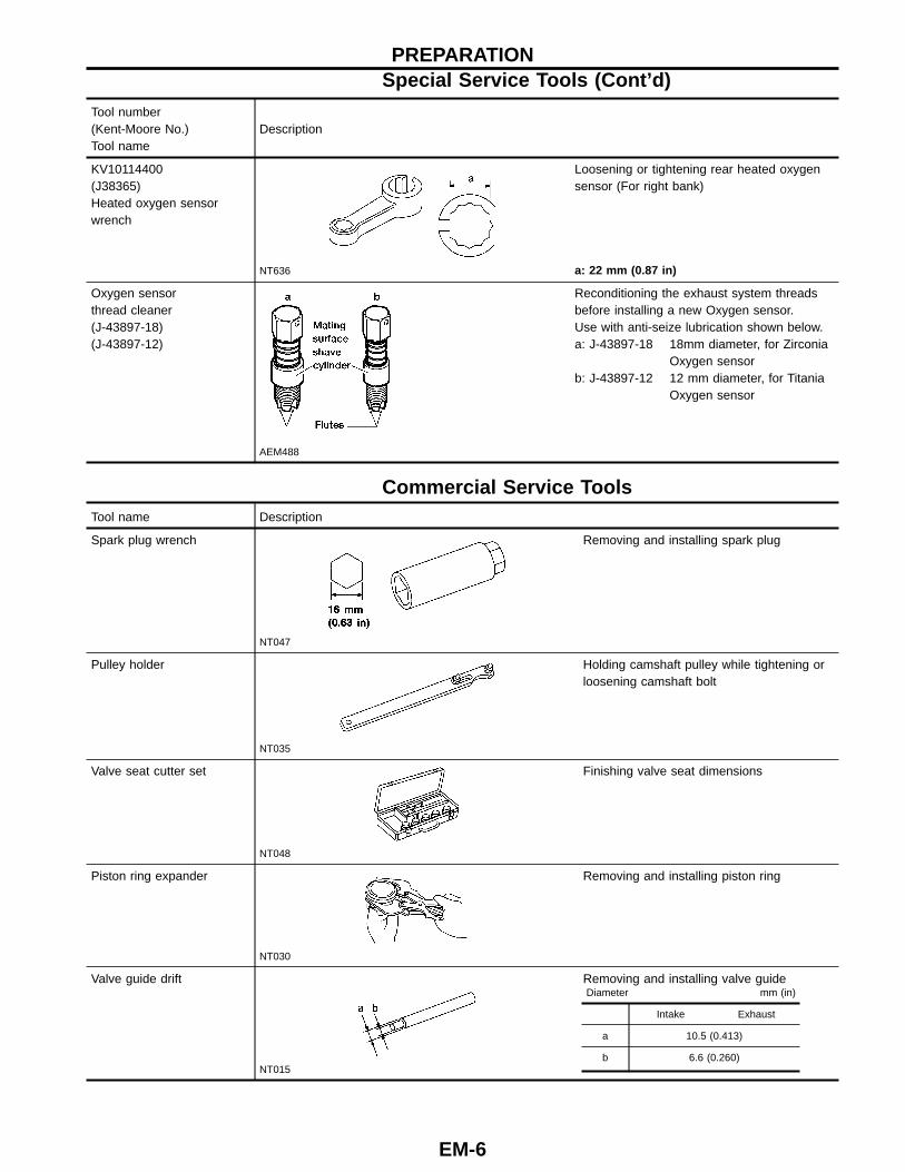
KV10114400(J38365)Heated oxygen sensorwrench
NT636
Loosening or tightening rear heated oxygensensor (For right bank)
a: 22 mm (0.87 in)
Oxygen sensorthread cleaner(J-43897-18)(J-43897-12)
AEM488
Reconditioning the exhaust system threadsbefore installing a new Oxygen sensor.Use with anti-seize lubrication shown below.a: J-43897-18 18mm diameter, for Zirconia
Oxygen sensorb: J-43897-12 12 mm diameter, for Titania
Oxygen sensor
Commercial Service ToolsTool name Description
Spark plug wrench
NT047
Removing and installing spark plug
Pulley holder
NT035
Holding camshaft pulley while tightening orloosening camshaft bolt
Valve seat cutter set
NT048
Finishing valve seat dimensions
Piston ring expander
NT030
Removing and installing piston ring
Valve guide drift
NT015
Removing and installing valve guideDiameter mm (in)
Intake Exhaust
a 10.5 (0.413)
b 6.6 (0.260)
PREPARATIONSpecial Service Tools (Cont ’d)
EM-6
Tool name Description
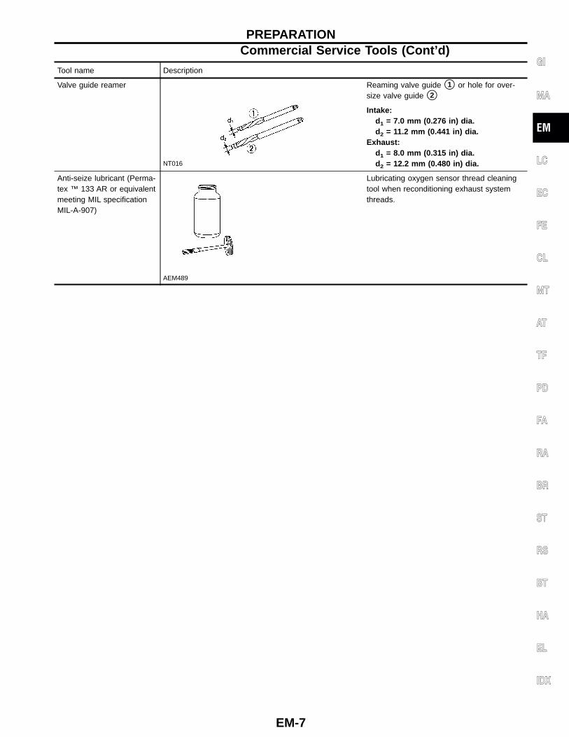
Valve guide reamer
NT016
Reaming valve guide �1 or hole for over-size valve guide �2
Intake:d1 = 7.0 mm (0.276 in) dia.d2 = 11.2 mm (0.441 in) dia.
Exhaust:d1 = 8.0 mm (0.315 in) dia.d2 = 12.2 mm (0.480 in) dia.
Anti-seize lubricant (Perma-tex ™ 133 AR or equivalentmeeting MIL specificationMIL-A-907)
AEM489
Lubricating oxygen sensor thread cleaningtool when reconditioning exhaust systemthreads.
GI
MA
EM
LC
EC
FE
CL
MT
AT
TF
PD
FA
RA
BR
ST
RS
BT
HA
EL
IDX
PREPARATIONCommercial Service Tools (Cont ’d)
EM-7
AEM459
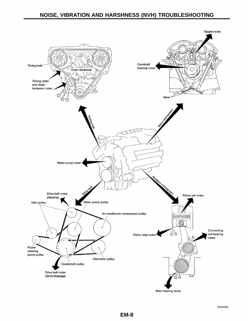
NOISE, VIBRATION AND HARSHNESS (NVH) TROUBLESHOOTING
EM-8
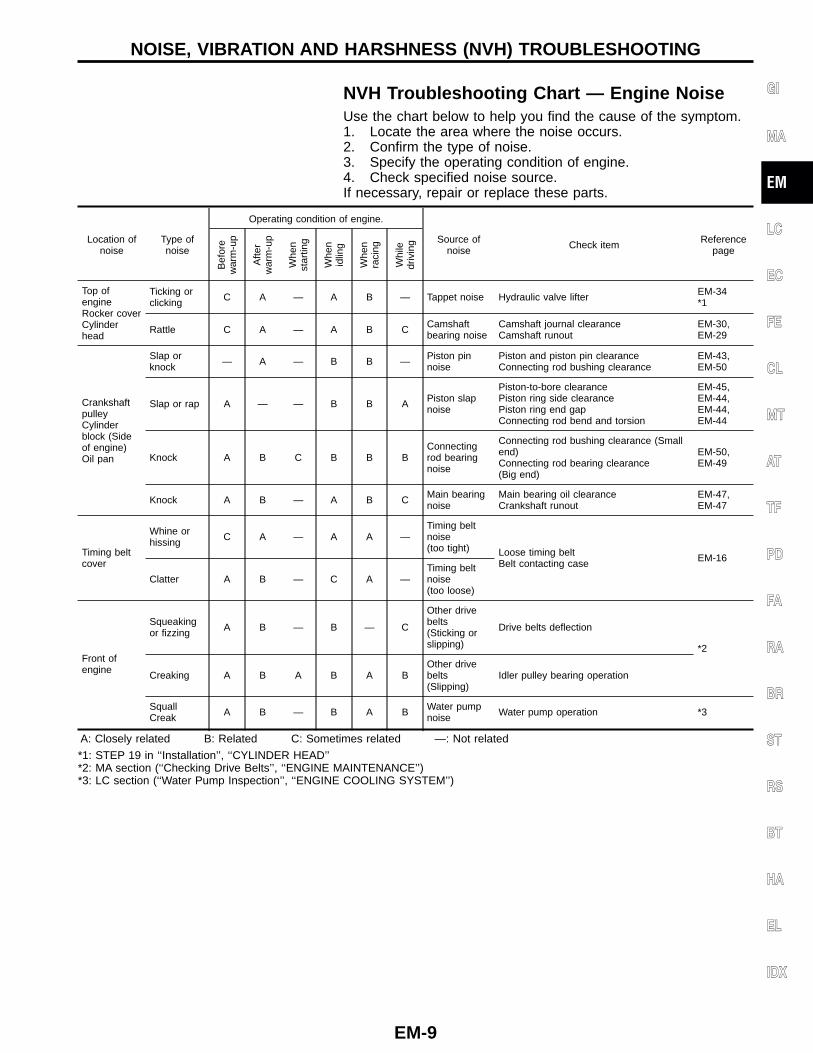
NVH Troubleshooting Chart — Engine NoiseUse the chart below to help you find the cause of the symptom.1. Locate the area where the noise occurs.2. Confirm the type of noise.3. Specify the operating condition of engine.4. Check specified noise source.If necessary, repair or replace these parts.
Location ofnoise
Type ofnoise
Operating condition of engine.
Source ofnoise Check item Reference
page
Bef
ore
war
m-u
p
Afte
rw
arm
-up
Whe
nst
artin
g
Whe
nid
ling
Whe
nra
cing
Whi
ledr
ivin
g
Top ofengineRocker coverCylinderhead
Ticking orclicking C A — A B — Tappet noise Hydraulic valve lifter EM-34
*1
Rattle C A — A B C Camshaftbearing noise
Camshaft journal clearanceCamshaft runout
EM-30,EM-29
CrankshaftpulleyCylinderblock (Sideof engine)Oil pan
Slap orknock — A — B B — Piston pin
noisePiston and piston pin clearanceConnecting rod bushing clearance
EM-43,EM-50
Slap or rap A — — B B A Piston slapnoise
Piston-to-bore clearancePiston ring side clearancePiston ring end gapConnecting rod bend and torsion
EM-45,EM-44,EM-44,EM-44
Knock A B C B B BConnectingrod bearingnoise
Connecting rod bushing clearance (Smallend)Connecting rod bearing clearance(Big end)
EM-50,EM-49
Knock A B — A B C Main bearingnoise
Main bearing oil clearanceCrankshaft runout
EM-47,EM-47
Timing beltcover
Whine orhissing C A — A A —
Timing beltnoise(too tight) Loose timing belt
Belt contacting case EM-16
Clatter A B — C A —Timing beltnoise(too loose)
Front ofengine
Squeakingor fizzing A B — B — C
Other drivebelts(Sticking orslipping)
Drive belts deflection
*2
Creaking A B A B A BOther drivebelts(Slipping)
Idler pulley bearing operation
SquallCreak A B — B A B Water pump
noise Water pump operation *3
A: Closely related B: Related C: Sometimes related —: Not related
*1: STEP 19 in ‘‘Installation’’, ‘‘CYLINDER HEAD’’*2: MA section (‘‘Checking Drive Belts’’, ‘‘ENGINE MAINTENANCE’’)*3: LC section (‘‘Water Pump Inspection’’, ‘‘ENGINE COOLING SYSTEM’’)
GI
MA
EM
LC
EC
FE
CL
MT
AT
TF
PD
FA
RA
BR
ST
RS
BT
HA
EL
IDX
NOISE, VIBRATION AND HARSHNESS (NVH) TROUBLESHOOTING
EM-9
AEM478
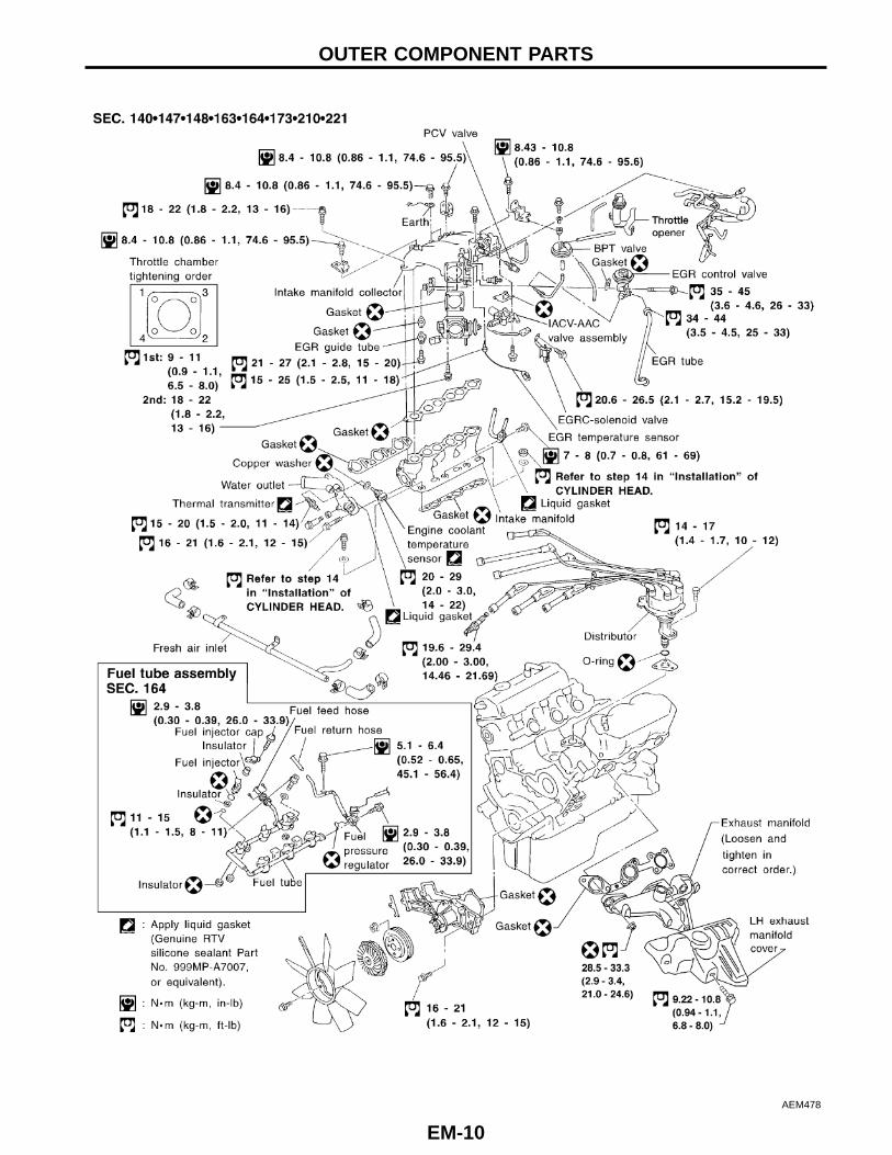
OUTER COMPONENT PARTS
EM-10
AEM474
GI
MA
EM
LC
EC
FE
CL
MT
AT
TF
PD
FA
RA
BR
ST
RS
BT
HA
EL
IDX
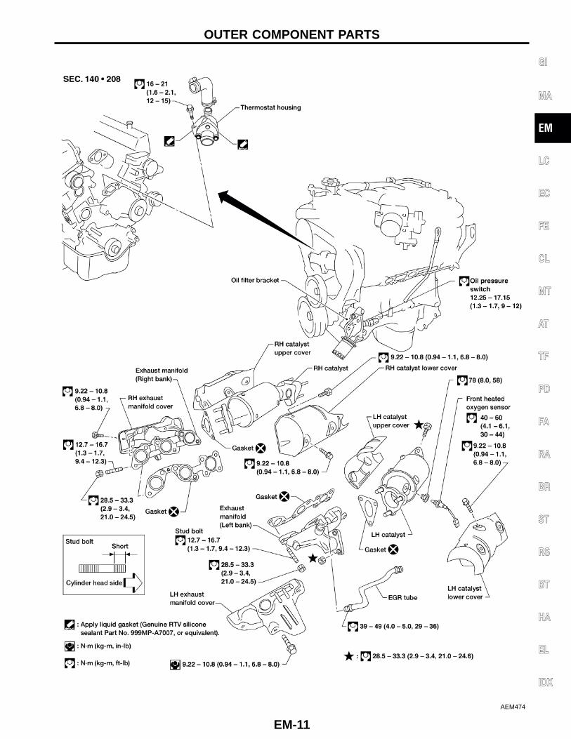
OUTER COMPONENT PARTS
EM-11
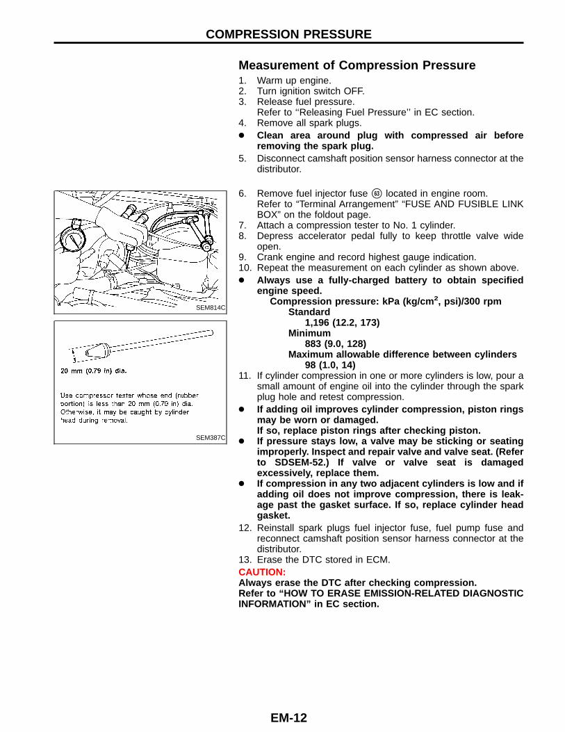
Measurement of Compression Pressure1. Warm up engine.2. Turn ignition switch OFF.3. Release fuel pressure.
Refer to ‘‘Releasing Fuel Pressure’’ in EC section.4. Remove all spark plugs.● Clean area around plug with compressed air before
removing the spark plug.5. Disconnect camshaft position sensor harness connector at the
distributor.
SEM814C
SEM387C
6. Remove fuel injector fuse �63 located in engine room.Refer to “Terminal Arrangement” “FUSE AND FUSIBLE LINKBOX” on the foldout page.
7. Attach a compression tester to No. 1 cylinder.8. Depress accelerator pedal fully to keep throttle valve wide
open.9. Crank engine and record highest gauge indication.10. Repeat the measurement on each cylinder as shown above.● Always use a fully-charged battery to obtain specified
engine speed.Compression pressure: kPa (kg/cm 2, psi)/300 rpm
Standard1,196 (12.2, 173)
Minimum883 (9.0, 128)
Maximum allowable difference between cylinders98 (1.0, 14)
11. If cylinder compression in one or more cylinders is low, pour asmall amount of engine oil into the cylinder through the sparkplug hole and retest compression.
● If adding oil improves cylinder compression, piston ringsmay be worn or damaged.If so, replace piston rings after checking piston.
● If pressure stays low, a valve may be sticking or seatingimproperly. Inspect and repair valve and valve seat. (Referto SDSEM-52.) If valve or valve seat is damagedexcessively, replace them.
● If compression in any two adjacent cylinders is low and ifadding oil does not improve compression, there is leak-age past the gasket surface. If so, replace cylinder headgasket.
12. Reinstall spark plugs fuel injector fuse, fuel pump fuse andreconnect camshaft position sensor harness connector at thedistributor.
13. Erase the DTC stored in ECM.CAUTION:Always erase the DTC after checking compression.Refer to “HOW TO ERASE EMISSION-RELATED DIAGNOSTICINFORMATION” in EC section.
COMPRESSION PRESSURE
EM-12
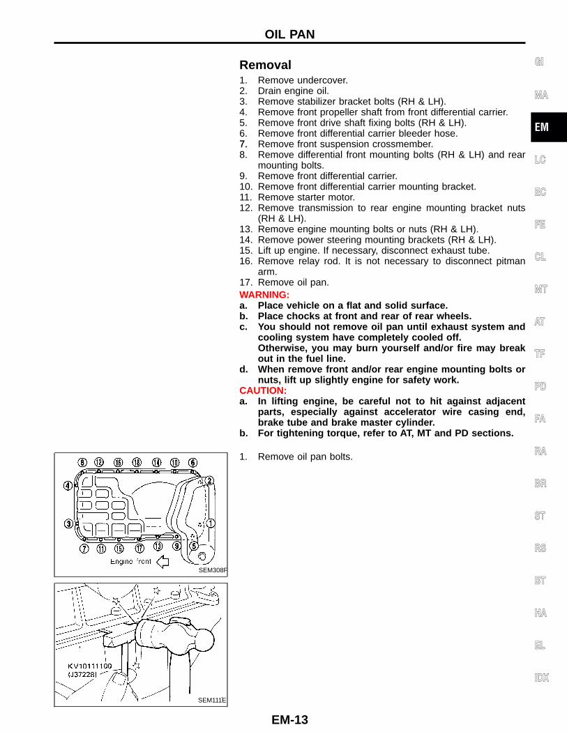
Removal1. Remove undercover.2. Drain engine oil.3. Remove stabilizer bracket bolts (RH & LH).4. Remove front propeller shaft from front differential carrier.5. Remove front drive shaft fixing bolts (RH & LH).6. Remove front differential carrier bleeder hose.7.7. Remove front suspension crossmember.8. Remove differential front mounting bolts (RH & LH) and rear
mounting bolts.9. Remove front differential carrier.10. Remove front differential carrier mounting bracket.11. Remove starter motor.12. Remove transmission to rear engine mounting bracket nuts
(RH & LH).13. Remove engine mounting bolts or nuts (RH & LH).14. Remove power steering mounting brackets (RH & LH).15. Lift up engine. If necessary, disconnect exhaust tube.16. Remove relay rod. It is not necessary to disconnect pitman
arm.17. Remove oil pan.WARNING:a. Place vehicle on a flat and solid surface.b. Place chocks at front and rear of rear wheels.c. You should not remove oil pan until exhaust system and
cooling system have completely cooled off.Otherwise, you may burn yourself and/or fire may breakout in the fuel line.
d. When remove front and/or rear engine mounting bolts ornuts, lift up slightly engine for safety work.
CAUTION:a. In lifting engine, be careful not to hit against adjacent
parts, especially against accelerator wire casing end,brake tube and brake master cylinder.
b. For tightening torque, refer to AT, MT and PD sections.
SEM308F
1. Remove oil pan bolts.
SEM111E
GI
MA
EM
LC
EC
FE
CL
MT
AT
TF
PD
FA
RA
BR
ST
RS
BT
HA
EL
IDX
OIL PAN
EM-13
SEM111E
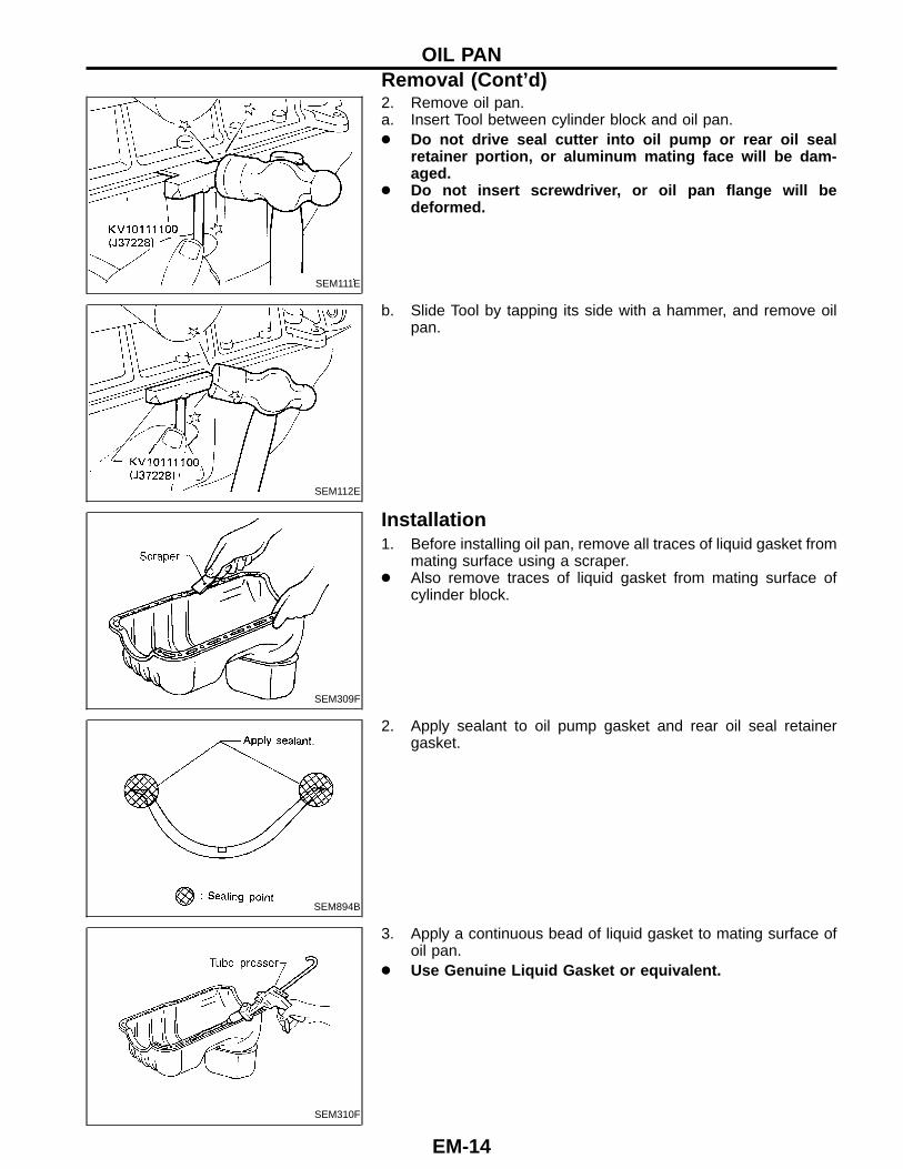
2. Remove oil pan.a. Insert Tool between cylinder block and oil pan.● Do not drive seal cutter into oil pump or rear oil seal
retainer portion, or aluminum mating face will be dam-aged.
● Do not insert screwdriver, or oil pan flange will bedeformed.
SEM112E
b. Slide Tool by tapping its side with a hammer, and remove oilpan.
SEM309F
Installation1. Before installing oil pan, remove all traces of liquid gasket from
mating surface using a scraper.● Also remove traces of liquid gasket from mating surface of
cylinder block.
SEM894B
2. Apply sealant to oil pump gasket and rear oil seal retainergasket.
SEM310F
3. Apply a continuous bead of liquid gasket to mating surface ofoil pan.
● Use Genuine Liquid Gasket or equivalent.
OIL PANRemoval (Cont ’d)
EM-14
SEM015E
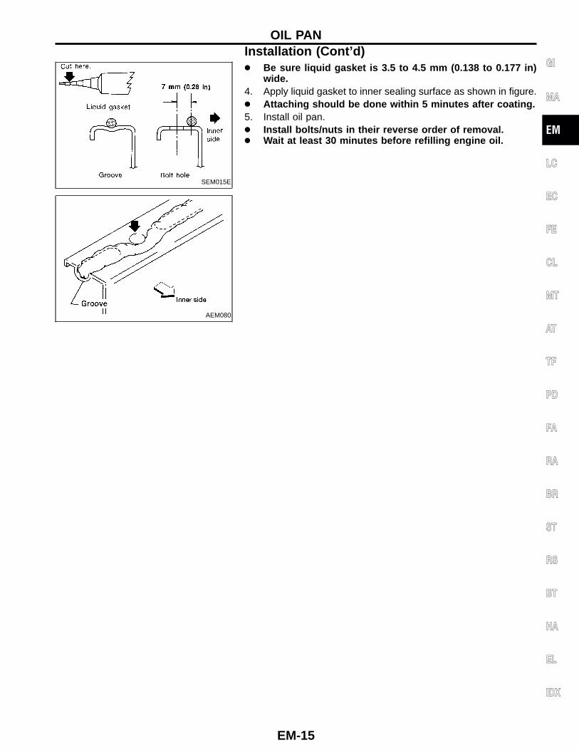
● Be sure liquid gasket is 3.5 to 4.5 mm (0.138 to 0.177 in)wide.
4. Apply liquid gasket to inner sealing surface as shown in figure.● Attaching should be done within 5 minutes after coating.5. Install oil pan.● Install bolts/nuts in their reverse order of removal.● Wait at least 30 minutes before refilling engine oil.
AEM080
GI
MA
EM
LC
EC
FE
CL
MT
AT
TF
PD
FA
RA
BR
ST
RS
BT
HA
EL
IDX
OIL PANInstallation (Cont ’d)
EM-15
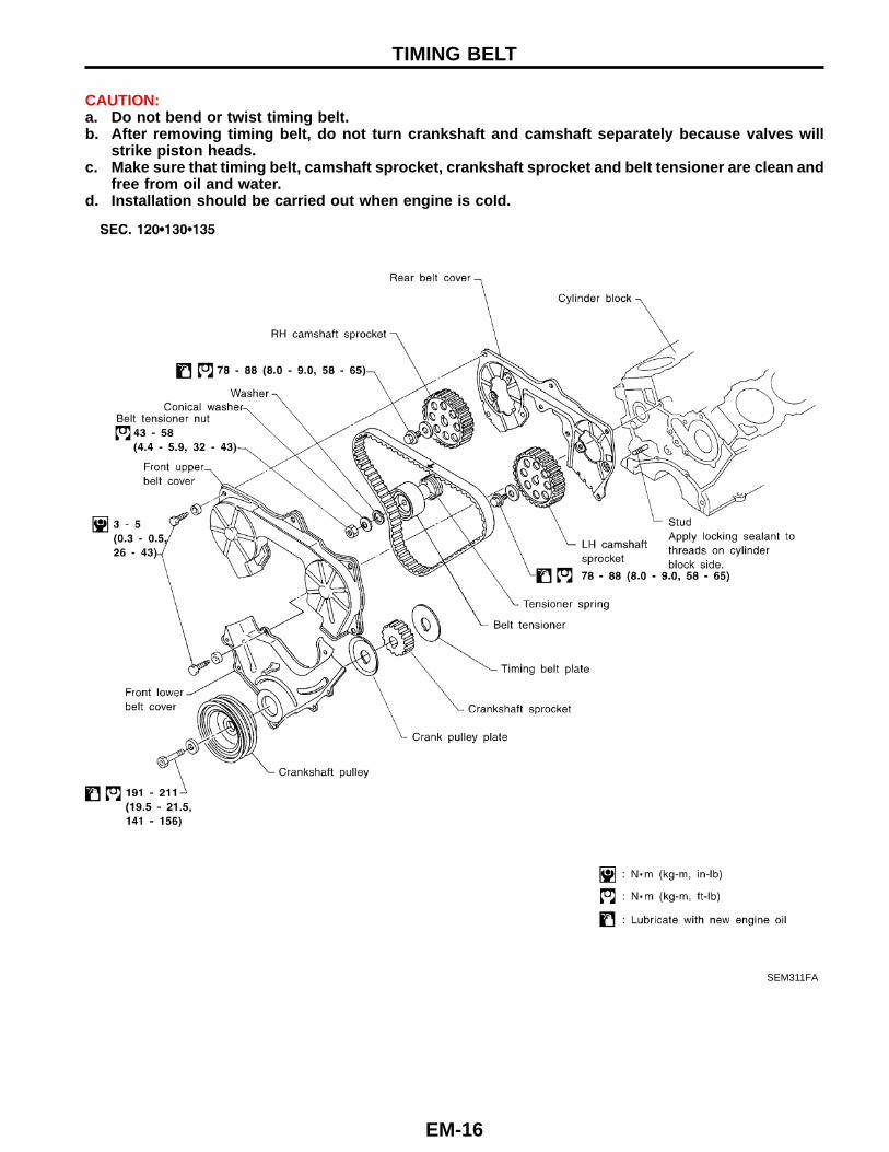
CAUTION:a. Do not bend or twist timing belt.b. After removing timing belt, do not turn crankshaft and camshaft separately because valves will
strike piston heads.c. Make sure that timing belt, camshaft sprocket, crankshaft sprocket and belt tensioner are clean and
free from oil and water.d. Installation should be carried out when engine is cold.
SEM311FA
TIMING BELT
EM-16
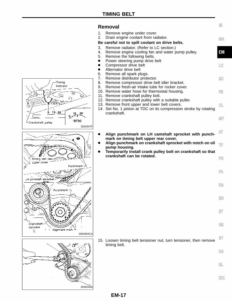
Removal
SEM347F
1. Remove engine under cover.2. Drain engine coolant from radiator.Be careful not to spill coolant on drive belts.3. Remove radiator. (Refer to LC section.)4. Remove engine cooling fan and water pump pulley.5. Remove the following belts.● Power steering pump drive belt● Compressor drive belt● Alternator drive belt6. Remove all spark plugs.7. Remove distributor protector.8. Remove compressor drive belt idler bracket.9. Remove fresh-air intake tube for rocker cover.10. Remove water hose for thermostat housing.11. Remove crankshaft pulley bolt.12. Remove crankshaft pulley with a suitable puller.13. Remove front upper and lower belt covers.14. Set No. 1 piston at TDC on its compression stroke by rotating
crankshaft.
SEM394CA
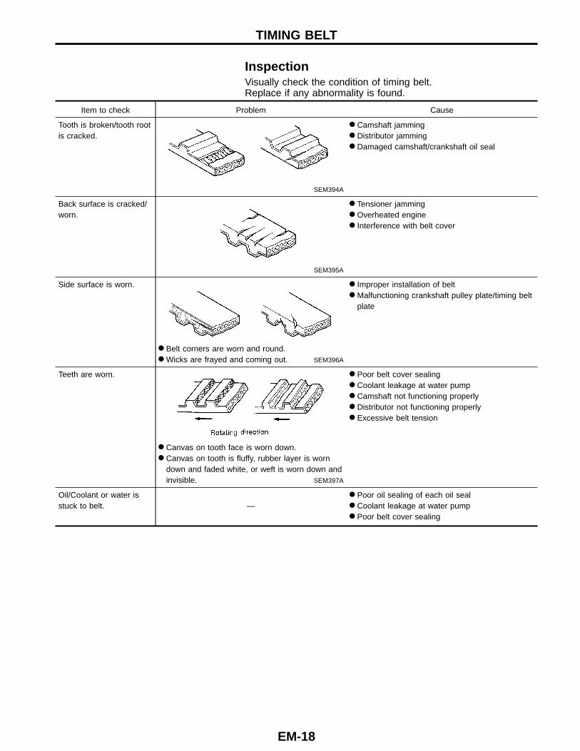
● Align punchmark on LH camshaft sprocket with punch-mark on timing belt upper rear cover.
● Align punchmark on crankshaft sprocket with notch on oilpump housing.
● Temporarily install crank pulley bolt on crankshaft so thatcrankshaft can be rotated.
SEM240A
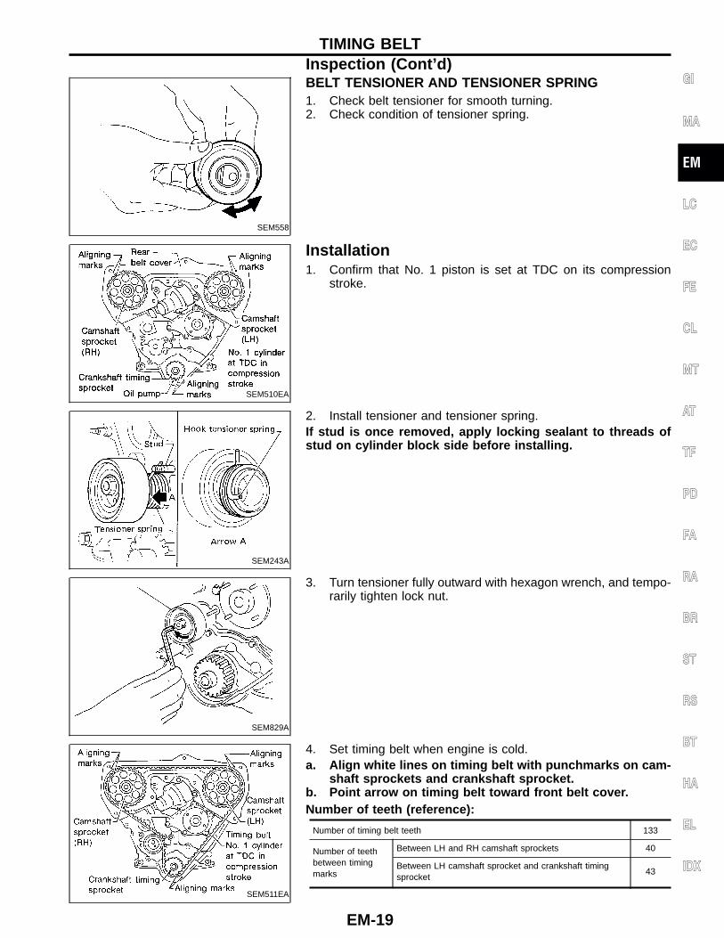
15. Loosen timing belt tensioner nut, turn tensioner, then removetiming belt.
GI
MA
EM
LC
EC
FE
CL
MT
AT
TF
PD
FA
RA
BR
ST
RS
BT
HA
EL
IDX
TIMING BELT
EM-17
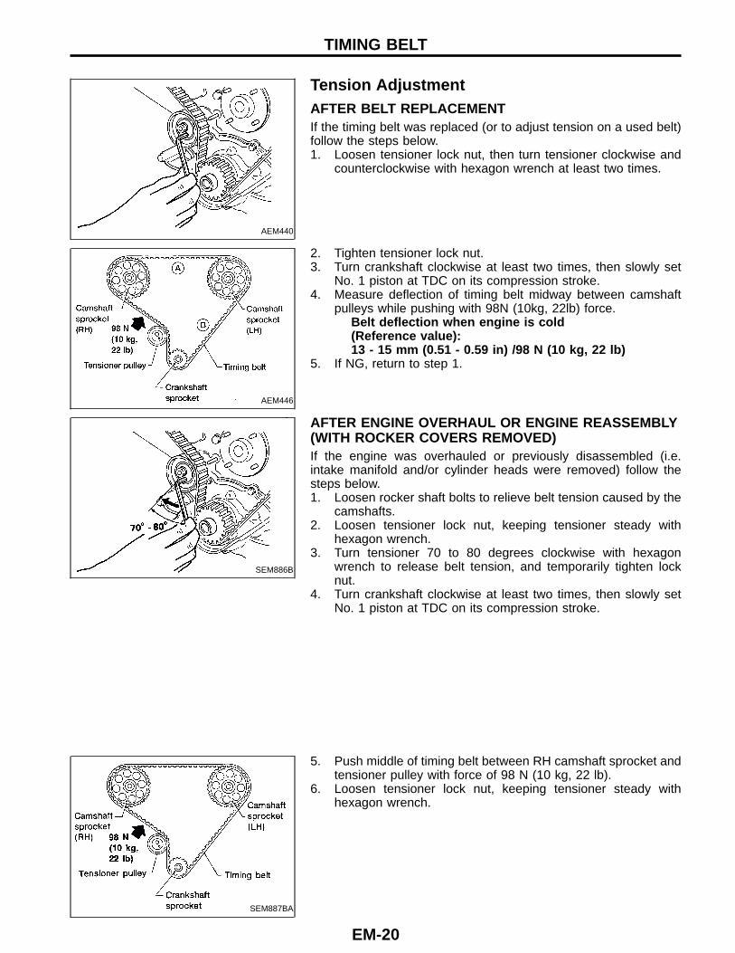
InspectionVisually check the condition of timing belt.Replace if any abnormality is found.
Item to check Problem Cause
Tooth is broken/tooth rootis cracked.
SEM394A
● Camshaft jamming● Distributor jamming● Damaged camshaft/crankshaft oil seal
Back surface is cracked/worn.
SEM395A
● Tensioner jamming● Overheated engine● Interference with belt cover
Side surface is worn.
● Belt corners are worn and round.● Wicks are frayed and coming out. SEM396A
● Improper installation of belt● Malfunctioning crankshaft pulley plate/timing belt
plate
Teeth are worn.
● Canvas on tooth face is worn down.● Canvas on tooth is fluffy, rubber layer is worn
down and faded white, or weft is worn down andinvisible. SEM397A
● Poor belt cover sealing● Coolant leakage at water pump● Camshaft not functioning properly● Distributor not functioning properly● Excessive belt tension
Oil/Coolant or water isstuck to belt. —
● Poor oil sealing of each oil seal● Coolant leakage at water pump● Poor belt cover sealing
TIMING BELT
EM-18
SEM558
BELT TENSIONER AND TENSIONER SPRING1. Check belt tensioner for smooth turning.2. Check condition of tensioner spring.
SEM510EA
Installation1. Confirm that No. 1 piston is set at TDC on its compression
stroke.
SEM243A
2. Install tensioner and tensioner spring.If stud is once removed, apply locking sealant to threads ofstud on cylinder block side before installing.
SEM829A
3. Turn tensioner fully outward with hexagon wrench, and tempo-rarily tighten lock nut.
SEM511EA
4. Set timing belt when engine is cold.a. Align white lines on timing belt with punchmarks on cam-
shaft sprockets and crankshaft sprocket.b. Point arrow on timing belt toward front belt cover.Number of teeth (reference):
Number of timing belt teeth 133
Number of teethbetween timingmarks
Between LH and RH camshaft sprockets 40
Between LH camshaft sprocket and crankshaft timingsprocket
43
GI
MA
EM
LC
EC
FE
CL
MT
AT
TF
PD
FA
RA
BR
ST
RS
BT
HA
EL
IDX
TIMING BELTInspection (Cont ’d)
EM-19
AEM440
Tension AdjustmentAFTER BELT REPLACEMENTIf the timing belt was replaced (or to adjust tension on a used belt)follow the steps below.1. Loosen tensioner lock nut, then turn tensioner clockwise and
counterclockwise with hexagon wrench at least two times.
AEM446
2. Tighten tensioner lock nut.3. Turn crankshaft clockwise at least two times, then slowly set
No. 1 piston at TDC on its compression stroke.4. Measure deflection of timing belt midway between camshaft
pulleys while pushing with 98N (10kg, 22lb) force.Belt deflection when engine is cold(Reference value):13 - 15 mm (0.51 - 0.59 in) /98 N (10 kg, 22 lb)
5. If NG, return to step 1.
SEM886B
AFTER ENGINE OVERHAUL OR ENGINE REASSEMBLY(WITH ROCKER COVERS REMOVED)If the engine was overhauled or previously disassembled (i.e.intake manifold and/or cylinder heads were removed) follow thesteps below.1. Loosen rocker shaft bolts to relieve belt tension caused by the
camshafts.2. Loosen tensioner lock nut, keeping tensioner steady with
hexagon wrench.3. Turn tensioner 70 to 80 degrees clockwise with hexagon
wrench to release belt tension, and temporarily tighten locknut.
4. Turn crankshaft clockwise at least two times, then slowly setNo. 1 piston at TDC on its compression stroke.
SEM887BA
5. Push middle of timing belt between RH camshaft sprocket andtensioner pulley with force of 98 N (10 kg, 22 lb).
6. Loosen tensioner lock nut, keeping tensioner steady withhexagon wrench.
TIMING BELT
EM-20
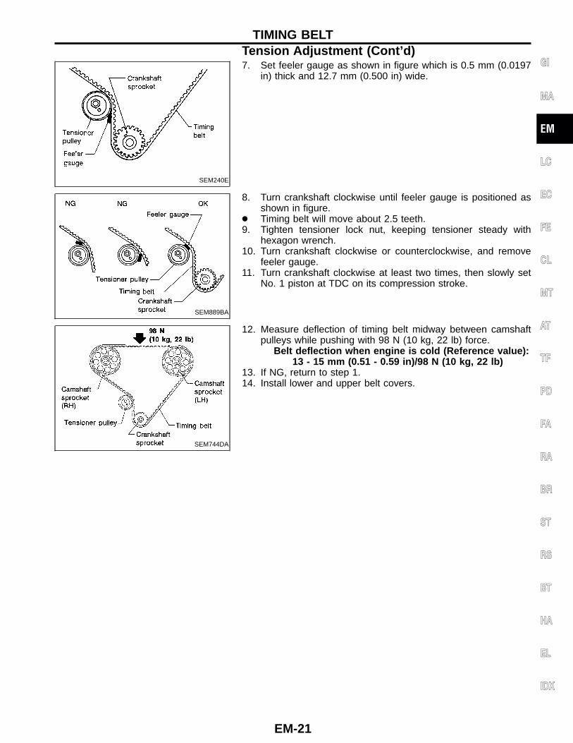
SEM240E
7. Set feeler gauge as shown in figure which is 0.5 mm (0.0197in) thick and 12.7 mm (0.500 in) wide.
SEM889BA
8. Turn crankshaft clockwise until feeler gauge is positioned asshown in figure.
● Timing belt will move about 2.5 teeth.9. Tighten tensioner lock nut, keeping tensioner steady with
hexagon wrench.10. Turn crankshaft clockwise or counterclockwise, and remove
feeler gauge.11. Turn crankshaft clockwise at least two times, then slowly set
No. 1 piston at TDC on its compression stroke.
SEM744DA
12. Measure deflection of timing belt midway between camshaftpulleys while pushing with 98 N (10 kg, 22 lb) force.
Belt deflection when engine is cold (Reference value):13 - 15 mm (0.51 - 0.59 in)/98 N (10 kg, 22 lb)
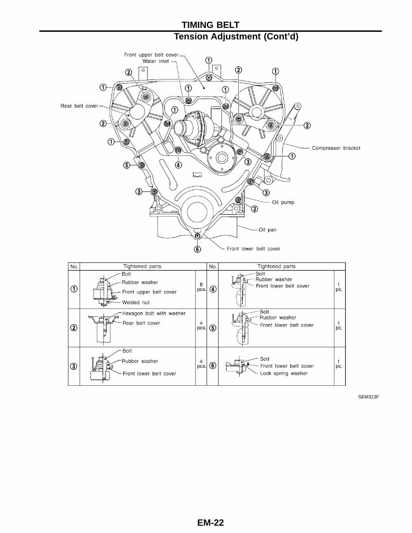
13. If NG, return to step 1.14. Install lower and upper belt covers.
GI
MA
EM
LC
EC
FE
CL
MT
AT
TF
PD
FA
RA
BR
ST
RS
BT
HA
EL
IDX
TIMING BELTTension Adjustment (Cont ’d)
EM-21
SEM313F
TIMING BELTTension Adjustment (Cont ’d)
EM-22
SEM257A
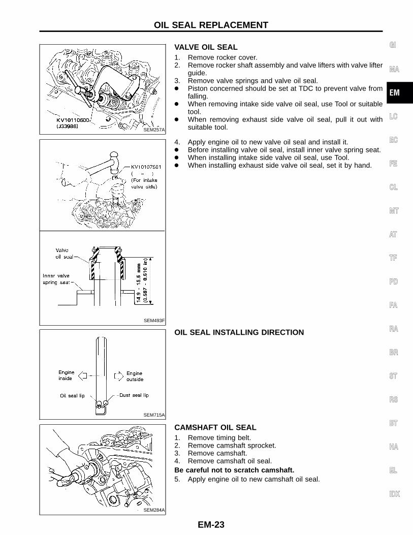
VALVE OIL SEAL1. Remove rocker cover.2. Remove rocker shaft assembly and valve lifters with valve lifter
guide.3. Remove valve springs and valve oil seal.● Piston concerned should be set at TDC to prevent valve from
falling.● When removing intake side valve oil seal, use Tool or suitable
tool.● When removing exhaust side valve oil seal, pull it out with
suitable tool.
SEM493F
4. Apply engine oil to new valve oil seal and install it.● Before installing valve oil seal, install inner valve spring seat.● When installing intake side valve oil seal, use Tool.● When installing exhaust side valve oil seal, set it by hand.
SEM715A
OIL SEAL INSTALLING DIRECTION
SEM284A
CAMSHAFT OIL SEAL1. Remove timing belt.2. Remove camshaft sprocket.3. Remove camshaft.4. Remove camshaft oil seal.Be careful not to scratch camshaft.5. Apply engine oil to new camshaft oil seal.
GI
MA
EM
LC
EC
FE
CL
MT
AT
TF
PD
FA
RA
BR
ST
RS
BT
HA
EL
IDX
OIL SEAL REPLACEMENT
EM-23
SEM241E
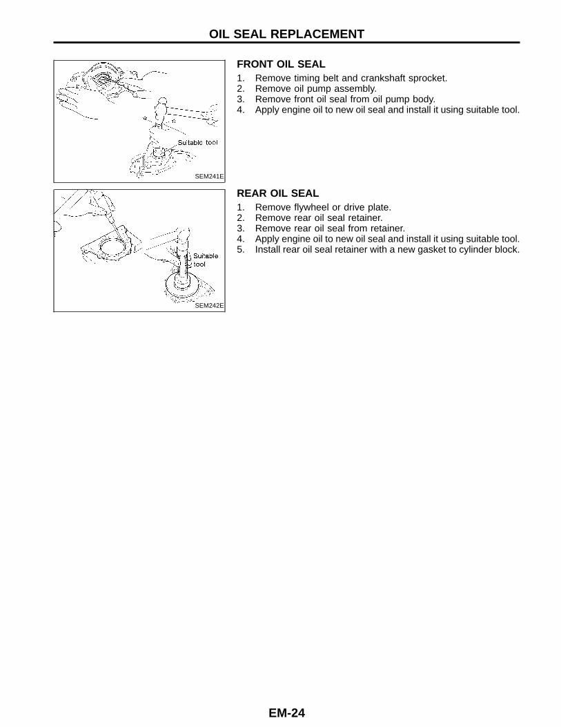
FRONT OIL SEAL1. Remove timing belt and crankshaft sprocket.2. Remove oil pump assembly.3. Remove front oil seal from oil pump body.4. Apply engine oil to new oil seal and install it using suitable tool.
SEM242E
REAR OIL SEAL1. Remove flywheel or drive plate.2. Remove rear oil seal retainer.3. Remove rear oil seal from retainer.4. Apply engine oil to new oil seal and install it using suitable tool.5. Install rear oil seal retainer with a new gasket to cylinder block.
OIL SEAL REPLACEMENT
EM-24
SEM314F
GI
MA
EM
LC
EC
FE
CL
MT
AT
TF
PD
FA
RA
BR
ST
RS
BT
HA
EL
IDX
CYLINDER HEAD
EM-25
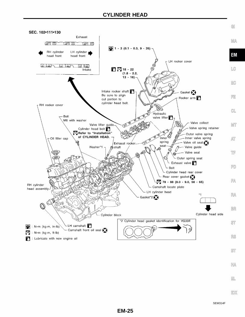
CAUTION:● When installing sliding parts such as rocker arms, cam-
shaft and oil seal, be sure to apply new engine oil on theirsliding surfaces.
● When tightening cylinder head bolts and rocker shaftbolts, apply new engine oil to thread portions and seatsurfaces of bolts.
SEM870BA
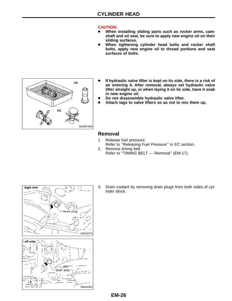
● If hydraulic valve lifter is kept on its side, there is a risk ofair entering it. After removal, always set hydraulic valvelifter straight up, or when laying it on its side, have it soakin new engine oil.
● Do not disassemble hydraulic valve lifter.● Attach tags to valve lifters so as not to mix them up.
Removal1. Release fuel pressure.
Refer to ‘‘Releasing Fuel Pressure’’ in EC section.2. Remove timing belt.
Refer to ‘‘TIMING BELT — Removal’’ (EM-17).
SMA207C
3. Drain coolant by removing drain plugs from both sides of cyl-inder block.
SMA208C
CYLINDER HEAD
EM-26
AEM442
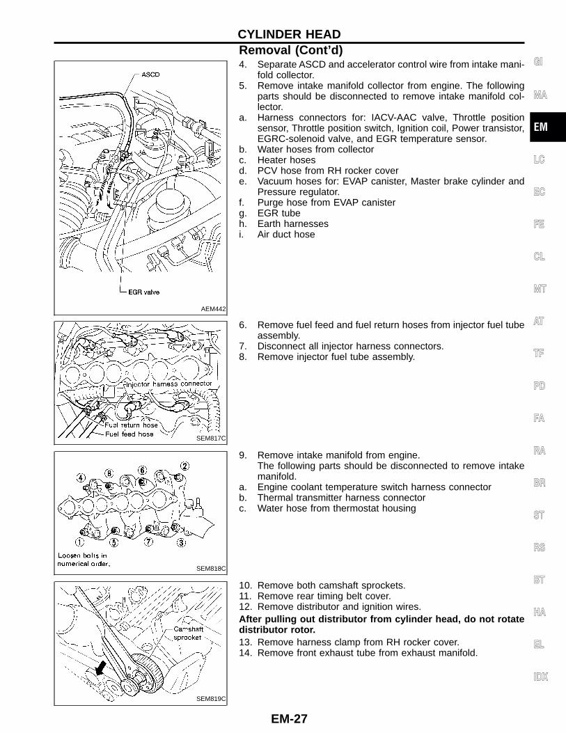
4. Separate ASCD and accelerator control wire from intake mani-fold collector.
5. Remove intake manifold collector from engine. The followingparts should be disconnected to remove intake manifold col-lector.
a. Harness connectors for: IACV-AAC valve, Throttle positionsensor, Throttle position switch, Ignition coil, Power transistor,EGRC-solenoid valve, and EGR temperature sensor.
b. Water hoses from collectorc. Heater hosesd. PCV hose from RH rocker covere. Vacuum hoses for: EVAP canister, Master brake cylinder and
Pressure regulator.f. Purge hose from EVAP canisterg. EGR tubeh. Earth harnessesi. Air duct hose
SEM817C
6. Remove fuel feed and fuel return hoses from injector fuel tubeassembly.
7. Disconnect all injector harness connectors.8. Remove injector fuel tube assembly.
SEM818C
9. Remove intake manifold from engine.The following parts should be disconnected to remove intakemanifold.
a. Engine coolant temperature switch harness connectorb. Thermal transmitter harness connectorc. Water hose from thermostat housing
SEM819C
10. Remove both camshaft sprockets.11. Remove rear timing belt cover.12. Remove distributor and ignition wires.After pulling out distributor from cylinder head, do not rotatedistributor rotor.13. Remove harness clamp from RH rocker cover.14. Remove front exhaust tube from exhaust manifold.
GI
MA
EM
LC
EC
FE
CL
MT
AT
TF
PD
FA
RA
BR
ST
RS
BT
HA
EL
IDX
CYLINDER HEADRemoval (Cont ’d)
EM-27
SEM316F
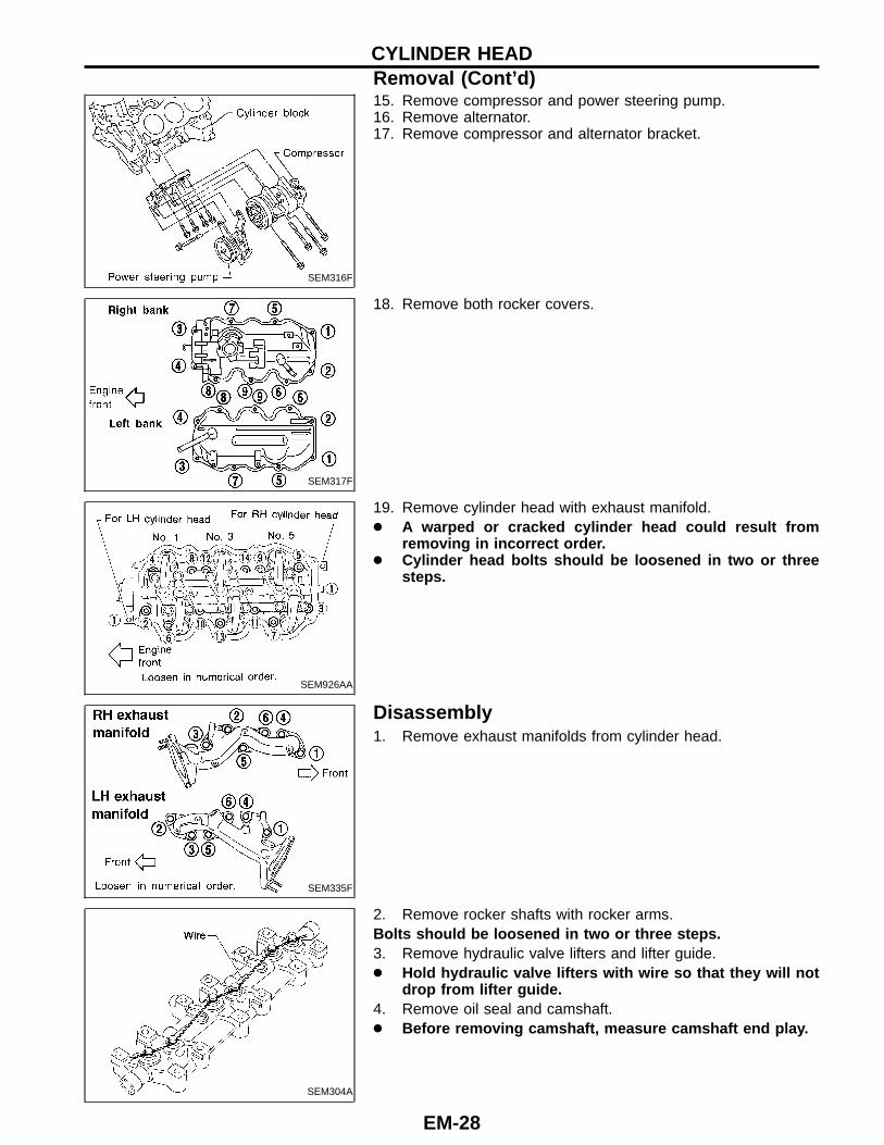
15. Remove compressor and power steering pump.16. Remove alternator.17. Remove compressor and alternator bracket.
SEM317F
18. Remove both rocker covers.
SEM926AA
19. Remove cylinder head with exhaust manifold.● A warped or cracked cylinder head could result from
removing in incorrect order.● Cylinder head bolts should be loosened in two or three
steps.
SEM335F
Disassembly1. Remove exhaust manifolds from cylinder head.
SEM304A
2. Remove rocker shafts with rocker arms.Bolts should be loosened in two or three steps.3. Remove hydraulic valve lifters and lifter guide.● Hold hydraulic valve lifters with wire so that they will not
drop from lifter guide.4. Remove oil seal and camshaft.● Before removing camshaft, measure camshaft end play.
CYLINDER HEADRemoval (Cont ’d)
EM-28
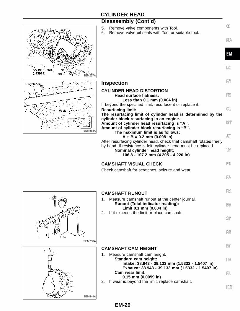
SEM257A
5. Remove valve components with Tool.6. Remove valve oil seals with Tool or suitable tool.
SEM868A
InspectionCYLINDER HEAD DISTORTION
Head surface flatness:Less than 0.1 mm (0.004 in)
If beyond the specified limit, resurface it or replace it.Resurfacing limit:The resurfacing limit of cylinder head is determined by thecylinder block resurfacing in an engine.Amount of cylinder head resurfacing is ‘‘A’’.Amount of cylinder block resurfacing is ‘‘B’’.
The maximum limit is as follows:A + B = 0.2 mm (0.008 in)
After resurfacing cylinder head, check that camshaft rotates freelyby hand. If resistance is felt, cylinder head must be replaced.
Nominal cylinder head height:106.8 - 107.2 mm (4.205 - 4.220 in)
CAMSHAFT VISUAL CHECKCheck camshaft for scratches, seizure and wear.
SEM758A
CAMSHAFT RUNOUT1. Measure camshaft runout at the center journal.
Runout (Total indicator reading):Limit 0.1 mm (0.004 in)
2. If it exceeds the limit, replace camshaft.
SEM549A
CAMSHAFT CAM HEIGHT1. Measure camshaft cam height.
Standard cam height:Intake: 38.943 - 39.133 mm (1.5332 - 1.5407 in)Exhaust: 38.943 - 39.133 mm (1.5332 - 1.5407 in)
Cam wear limit:0.15 mm (0.0059 in)
2. If wear is beyond the limit, replace camshaft.
GI
MA
EM
LC
EC
FE
CL
MT
AT
TF
PD
FA
RA
BR
ST
RS
BT
HA
EL
IDX
CYLINDER HEADDisassembly (Cont ’d)
EM-29
SEM893BA
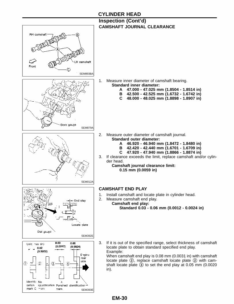
CAMSHAFT JOURNAL CLEARANCE
SEM879A
1. Measure inner diameter of camshaft bearing.Standard inner diameter:
A 47.000 - 47.025 mm (1.8504 - 1.8514 in)B 42.500 - 42.525 mm (1.6732 - 1.6742 in)C 48.000 - 48.025 mm (1.8898 - 1.8907 in)
SEM012A
2. Measure outer diameter of camshaft journal.Standard outer diameter:
A 46.920 - 46.940 mm (1.8472 - 1.8480 in)B 42.420 - 42.440 mm (1.6701 - 1.6709 in)C 47.920 - 47.940 mm (1.8866 - 1.8874 in)
3. If clearance exceeds the limit, replace camshaft and/or cylin-der head.
Camshaft journal clearance limit:0.15 mm (0.0059 in)
SEM392E
CAMSHAFT END PLAY1. Install camshaft and locate plate in cylinder head.2. Measure camshaft end play.
Camshaft end play:Standard 0.03 - 0.06 mm (0.0012 - 0.0024 in)
SEM393E
3. If it is out of the specified range, select thickness of camshaftlocate plate to obtain standard specified end play.Example:When camshaft end play is 0.08 mm (0.0031 in) with camshaftlocate plate �2 , replace camshaft locate plate �2 with cam-shaft locate plate �3 to set the end play at 0.05 mm (0.0020in).
CYLINDER HEADInspection (Cont ’d)
EM-30
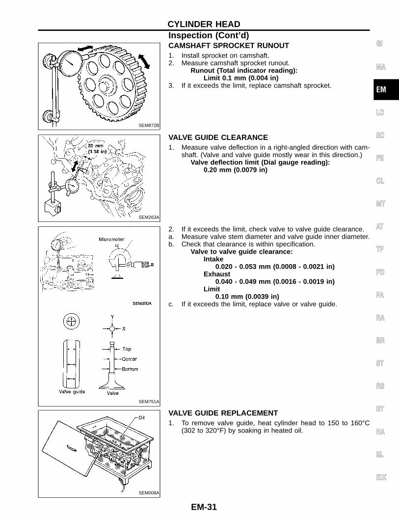
SEM872B
CAMSHAFT SPROCKET RUNOUT1. Install sprocket on camshaft.2. Measure camshaft sprocket runout.
Runout (Total indicator reading):Limit 0.1 mm (0.004 in)
3. If it exceeds the limit, replace camshaft sprocket.
SEM263A
VALVE GUIDE CLEARANCE1. Measure valve deflection in a right-angled direction with cam-
shaft. (Valve and valve guide mostly wear in this direction.)Valve deflection limit (Dial gauge reading):
0.20 mm (0.0079 in)
SEM751A
2. If it exceeds the limit, check valve to valve guide clearance.a. Measure valve stem diameter and valve guide inner diameter.b. Check that clearance is within specification.
Valve to valve guide clearance:Intake
0.020 - 0.053 mm (0.0008 - 0.0021 in)Exhaust
0.040 - 0.049 mm (0.0016 - 0.0019 in)Limit
0.10 mm (0.0039 in)c. If it exceeds the limit, replace valve or valve guide.
SEM008A
VALVE GUIDE REPLACEMENT1. To remove valve guide, heat cylinder head to 150 to 160°C
(302 to 320°F) by soaking in heated oil.
GI
MA
EM
LC
EC
FE
CL
MT
AT
TF
PD
FA
RA
BR
ST
RS
BT
HA
EL
IDX
CYLINDER HEADInspection (Cont ’d)
EM-31
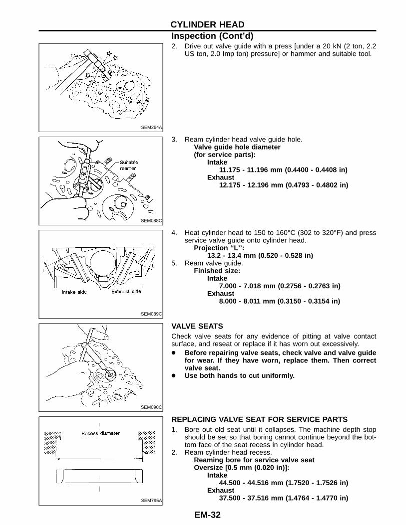
SEM264A
2. Drive out valve guide with a press [under a 20 kN (2 ton, 2.2US ton, 2.0 Imp ton) pressure] or hammer and suitable tool.
SEM088C
3. Ream cylinder head valve guide hole.Valve guide hole diameter(for service parts):
Intake11.175 - 11.196 mm (0.4400 - 0.4408 in)
Exhaust12.175 - 12.196 mm (0.4793 - 0.4802 in)
SEM089C
4. Heat cylinder head to 150 to 160°C (302 to 320°F) and pressservice valve guide onto cylinder head.
Projection ‘‘L’’:13.2 - 13.4 mm (0.520 - 0.528 in)
5. Ream valve guide.Finished size:
Intake7.000 - 7.018 mm (0.2756 - 0.2763 in)
Exhaust8.000 - 8.011 mm (0.3150 - 0.3154 in)
SEM090C
VALVE SEATSCheck valve seats for any evidence of pitting at valve contactsurface, and reseat or replace if it has worn out excessively.● Before repairing valve seats, check valve and valve guide
for wear. If they have worn, replace them. Then correctvalve seat.
● Use both hands to cut uniformly.
SEM795A
REPLACING VALVE SEAT FOR SERVICE PARTS1. Bore out old seat until it collapses. The machine depth stop
should be set so that boring cannot continue beyond the bot-tom face of the seat recess in cylinder head.
2. Ream cylinder head recess.Reaming bore for service valve seatOversize [0.5 mm (0.020 in)]:
Intake44.500 - 44.516 mm (1.7520 - 1.7526 in)
Exhaust37.500 - 37.516 mm (1.4764 - 1.4770 in)
CYLINDER HEADInspection (Cont ’d)
EM-32
Reaming should be done in circles concentric to the valveguide center so that valve seat will have the correct fit.3. Heat cylinder head to 150 to 160°C (302 to 320°F) by soaking
in heated oil.4. Press fit valve seat until it seats on the bottom.
SEM892B
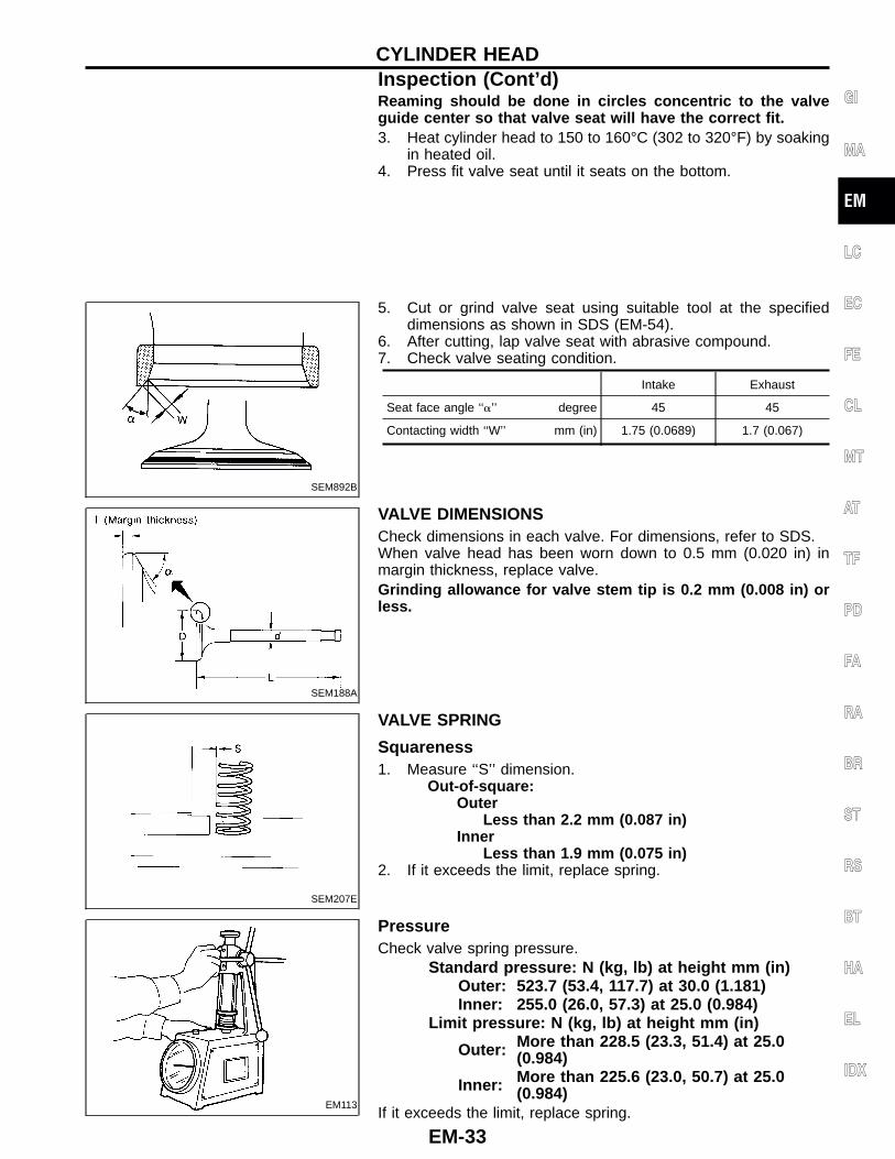
5. Cut or grind valve seat using suitable tool at the specifieddimensions as shown in SDS (EM-54).
6. After cutting, lap valve seat with abrasive compound.7. Check valve seating condition.
Intake Exhaust
Seat face angle ‘‘�’’ degree 45 45
Contacting width ‘‘W’’ mm (in) 1.75 (0.0689) 1.7 (0.067)
SEM188A
VALVE DIMENSIONSCheck dimensions in each valve. For dimensions, refer to SDS.When valve head has been worn down to 0.5 mm (0.020 in) inmargin thickness, replace valve.Grinding allowance for valve stem tip is 0.2 mm (0.008 in) orless.
SEM207E
VALVE SPRING
Squareness1. Measure ‘‘S’’ dimension.
Out-of-square:Outer
Less than 2.2 mm (0.087 in)Inner
Less than 1.9 mm (0.075 in)2. If it exceeds the limit, replace spring.
EM113
PressureCheck valve spring pressure.
Standard pressure: N (kg, lb) at height mm (in)Outer: 523.7 (53.4, 117.7) at 30.0 (1.181)Inner: 255.0 (26.0, 57.3) at 25.0 (0.984)
Limit pressure: N (kg, lb) at height mm (in)
Outer: More than 228.5 (23.3, 51.4) at 25.0(0.984)
Inner: More than 225.6 (23.0, 50.7) at 25.0(0.984)
If it exceeds the limit, replace spring.
GI
MA
EM
LC
EC
FE
CL
MT
AT
TF
PD
FA
RA
BR
ST
RS
BT
HA
EL
IDX
CYLINDER HEADInspection (Cont ’d)
EM-33
SEM761A
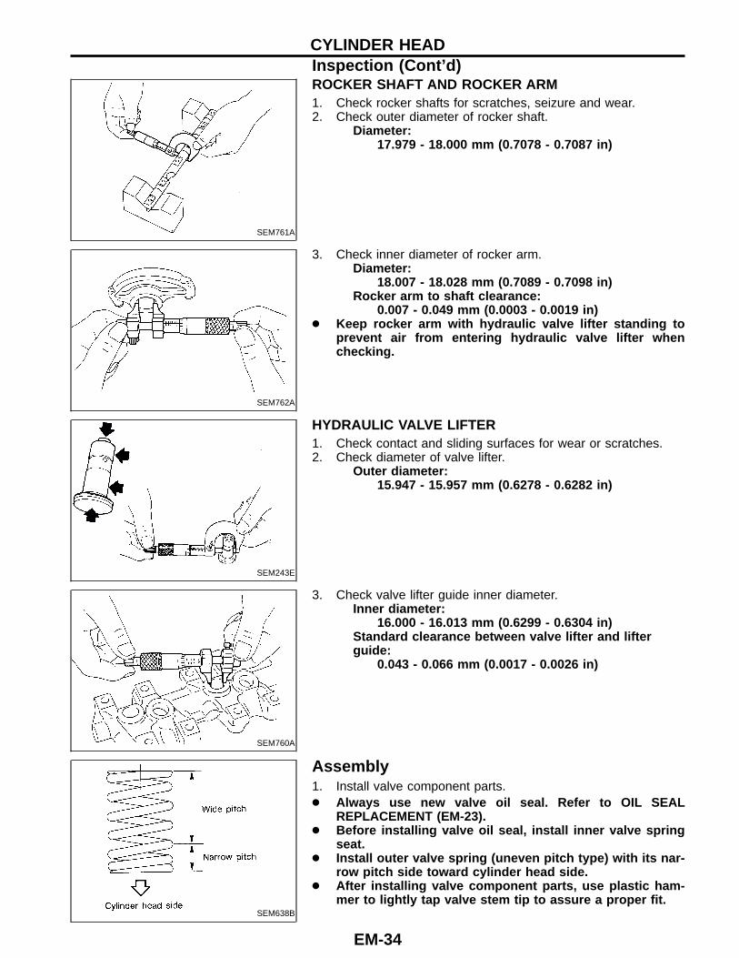
ROCKER SHAFT AND ROCKER ARM1. Check rocker shafts for scratches, seizure and wear.2. Check outer diameter of rocker shaft.
Diameter:17.979 - 18.000 mm (0.7078 - 0.7087 in)
SEM762A
3. Check inner diameter of rocker arm.Diameter:
18.007 - 18.028 mm (0.7089 - 0.7098 in)Rocker arm to shaft clearance:
0.007 - 0.049 mm (0.0003 - 0.0019 in)● Keep rocker arm with hydraulic valve lifter standing to
prevent air from entering hydraulic valve lifter whenchecking.
SEM243E
HYDRAULIC VALVE LIFTER1. Check contact and sliding surfaces for wear or scratches.2. Check diameter of valve lifter.
Outer diameter:15.947 - 15.957 mm (0.6278 - 0.6282 in)
SEM760A
3. Check valve lifter guide inner diameter.Inner diameter:
16.000 - 16.013 mm (0.6299 - 0.6304 in)Standard clearance between valve lifter and lifterguide:
0.043 - 0.066 mm (0.0017 - 0.0026 in)
SEM638B
Assembly1. Install valve component parts.● Always use new valve oil seal. Refer to OIL SEAL
REPLACEMENT (EM-23).● Before installing valve oil seal, install inner valve spring
seat.● Install outer valve spring (uneven pitch type) with its nar-
row pitch side toward cylinder head side.● After installing valve component parts, use plastic ham-
mer to lightly tap valve stem tip to assure a proper fit.
CYLINDER HEADInspection (Cont ’d)
EM-34
SEM834B
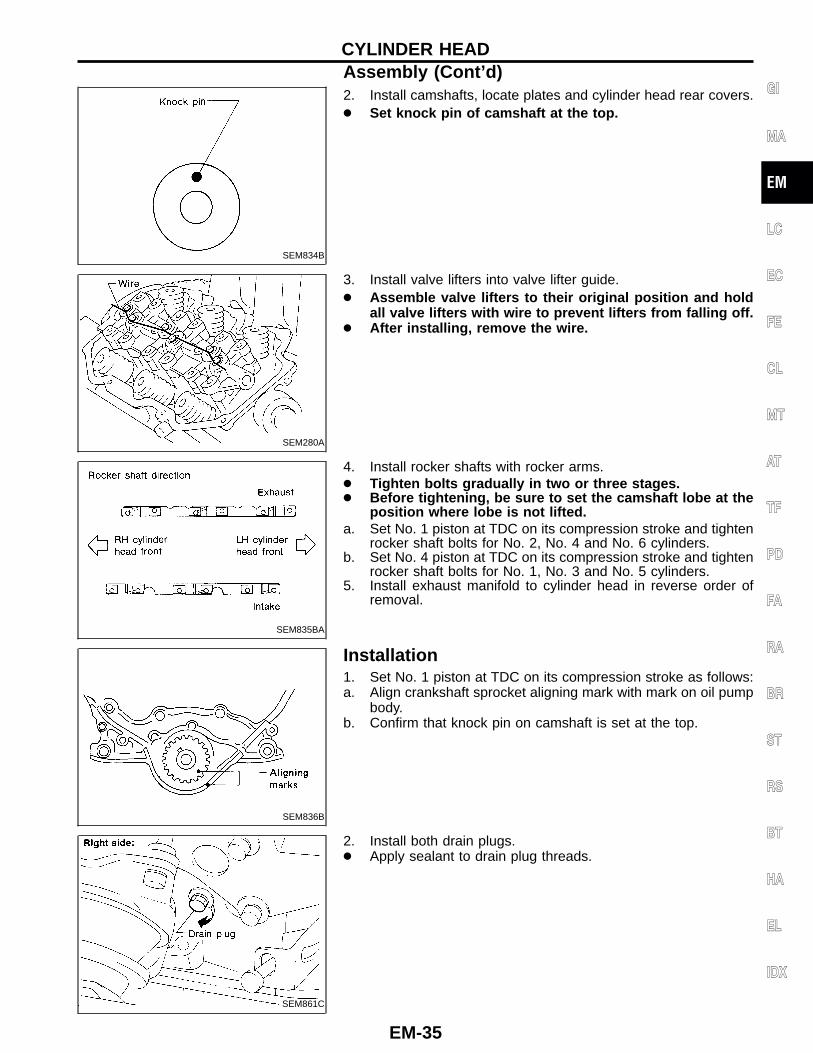
2. Install camshafts, locate plates and cylinder head rear covers.● Set knock pin of camshaft at the top.
SEM280A
3. Install valve lifters into valve lifter guide.● Assemble valve lifters to their original position and hold
all valve lifters with wire to prevent lifters from falling off.● After installing, remove the wire.
SEM835BA
4. Install rocker shafts with rocker arms.● Tighten bolts gradually in two or three stages.● Before tightening, be sure to set the camshaft lobe at the
position where lobe is not lifted.a. Set No. 1 piston at TDC on its compression stroke and tighten
rocker shaft bolts for No. 2, No. 4 and No. 6 cylinders.b. Set No. 4 piston at TDC on its compression stroke and tighten
rocker shaft bolts for No. 1, No. 3 and No. 5 cylinders.5. Install exhaust manifold to cylinder head in reverse order of
removal.
SEM836B
Installation1. Set No. 1 piston at TDC on its compression stroke as follows:a. Align crankshaft sprocket aligning mark with mark on oil pump
body.b. Confirm that knock pin on camshaft is set at the top.
SEM861C
2. Install both drain plugs.● Apply sealant to drain plug threads.
GI
MA
EM
LC
EC
FE
CL
MT
AT
TF
PD
FA
RA
BR
ST
RS
BT
HA
EL
IDX
CYLINDER HEADAssembly (Cont ’d)
EM-35
SEM862C
SEM336F
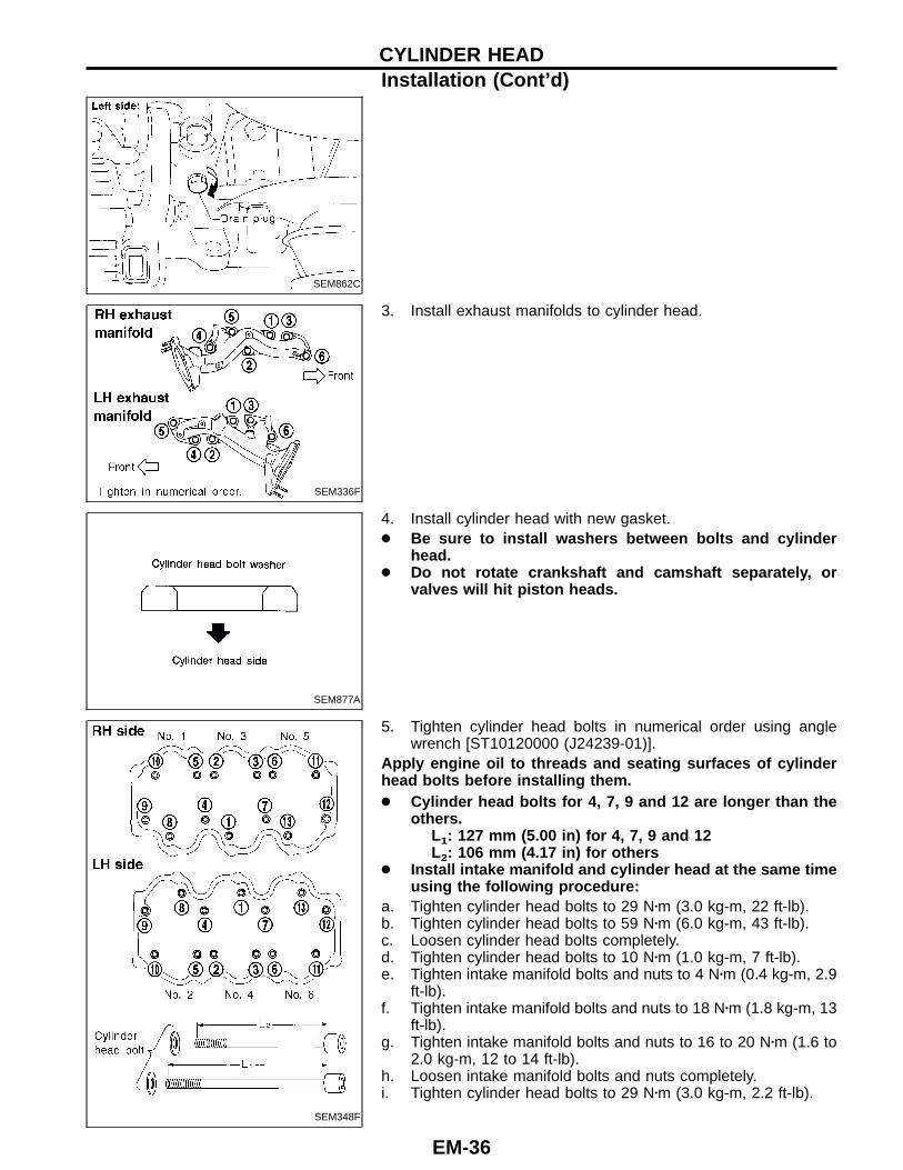
3. Install exhaust manifolds to cylinder head.
SEM877A
4. Install cylinder head with new gasket.● Be sure to install washers between bolts and cylinder
head.● Do not rotate crankshaft and camshaft separately, or
valves will hit piston heads.
SEM348F
5. Tighten cylinder head bolts in numerical order using anglewrench [ST10120000 (J24239-01)].
Apply engine oil to threads and seating surfaces of cylinderhead bolts before installing them.● Cylinder head bolts for 4, 7, 9 and 12 are longer than the
others.L1: 127 mm (5.00 in) for 4, 7, 9 and 12L2: 106 mm (4.17 in) for others
● Install intake manifold and cylinder head at the same timeusing the following procedure:
a. Tighten cylinder head bolts to 29 N�m (3.0 kg-m, 22 ft-lb).b. Tighten cylinder head bolts to 59 N�m (6.0 kg-m, 43 ft-lb).c. Loosen cylinder head bolts completely.d. Tighten cylinder head bolts to 10 N�m (1.0 kg-m, 7 ft-lb).e. Tighten intake manifold bolts and nuts to 4 N�m (0.4 kg-m, 2.9
ft-lb).f. Tighten intake manifold bolts and nuts to 18 N�m (1.8 kg-m, 13
ft-lb).g. Tighten intake manifold bolts and nuts to 16 to 20 N�m (1.6 to
2.0 kg-m, 12 to 14 ft-lb).h. Loosen intake manifold bolts and nuts completely.i. Tighten cylinder head bolts to 29 N�m (3.0 kg-m, 2.2 ft-lb).
CYLINDER HEADInstallation (Cont ’d)
EM-36
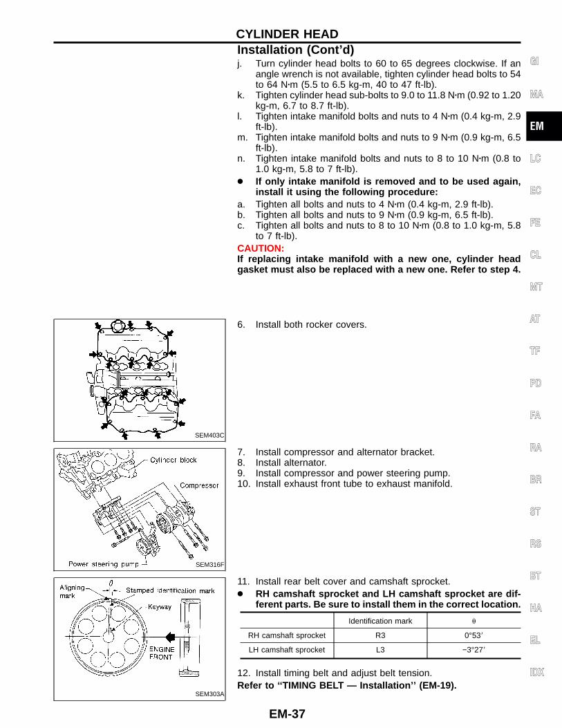
j. Turn cylinder head bolts to 60 to 65 degrees clockwise. If anangle wrench is not available, tighten cylinder head bolts to 54to 64 N�m (5.5 to 6.5 kg-m, 40 to 47 ft-lb).
k. Tighten cylinder head sub-bolts to 9.0 to 11.8 N�m (0.92 to 1.20kg-m, 6.7 to 8.7 ft-lb).
l. Tighten intake manifold bolts and nuts to 4 N�m (0.4 kg-m, 2.9ft-lb).
m. Tighten intake manifold bolts and nuts to 9 N�m (0.9 kg-m, 6.5ft-lb).
n. Tighten intake manifold bolts and nuts to 8 to 10 N�m (0.8 to1.0 kg-m, 5.8 to 7 ft-lb).
● If only intake manifold is removed and to be used again,install it using the following procedure:
a. Tighten all bolts and nuts to 4 N�m (0.4 kg-m, 2.9 ft-lb).b. Tighten all bolts and nuts to 9 N�m (0.9 kg-m, 6.5 ft-lb).c. Tighten all bolts and nuts to 8 to 10 N�m (0.8 to 1.0 kg-m, 5.8
to 7 ft-lb).CAUTION:If replacing intake manifold with a new one, cylinder headgasket must also be replaced with a new one. Refer to step 4.
SEM403C
6. Install both rocker covers.
SEM316F
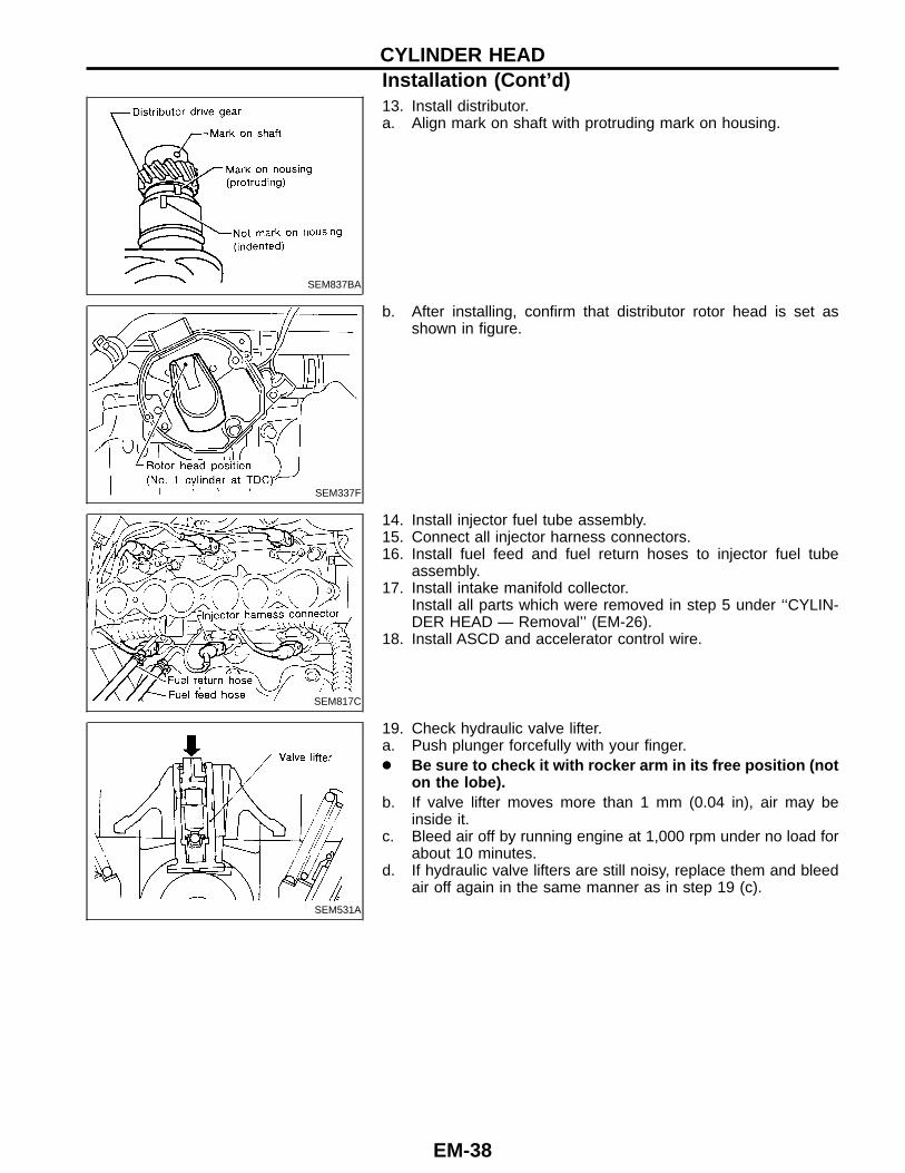
7. Install compressor and alternator bracket.8. Install alternator.9. Install compressor and power steering pump.10. Install exhaust front tube to exhaust manifold.
SEM303A
11. Install rear belt cover and camshaft sprocket.● RH camshaft sprocket and LH camshaft sprocket are dif-
ferent parts. Be sure to install them in the correct location.
Identification mark �
RH camshaft sprocket R3 0°53�
LH camshaft sprocket L3 −3°27�
12. Install timing belt and adjust belt tension.Refer to ‘‘TIMING BELT — Installation ’’ (EM-19).
GI
MA
EM
LC
EC
FE
CL
MT
AT
TF
PD
FA
RA
BR
ST
RS
BT
HA
EL
IDX
CYLINDER HEADInstallation (Cont ’d)
EM-37
SEM837BA
13. Install distributor.a. Align mark on shaft with protruding mark on housing.
SEM337F
b. After installing, confirm that distributor rotor head is set asshown in figure.
SEM817C
14. Install injector fuel tube assembly.15. Connect all injector harness connectors.16. Install fuel feed and fuel return hoses to injector fuel tube
assembly.17. Install intake manifold collector.
Install all parts which were removed in step 5 under ‘‘CYLIN-DER HEAD — Removal’’ (EM-26).
18. Install ASCD and accelerator control wire.
SEM531A
19. Check hydraulic valve lifter.a. Push plunger forcefully with your finger.● Be sure to check it with rocker arm in its free position (not
on the lobe).b. If valve lifter moves more than 1 mm (0.04 in), air may be
inside it.c. Bleed air off by running engine at 1,000 rpm under no load for
about 10 minutes.d. If hydraulic valve lifters are still noisy, replace them and bleed
air off again in the same manner as in step 19 (c).
CYLINDER HEADInstallation (Cont ’d)
EM-38
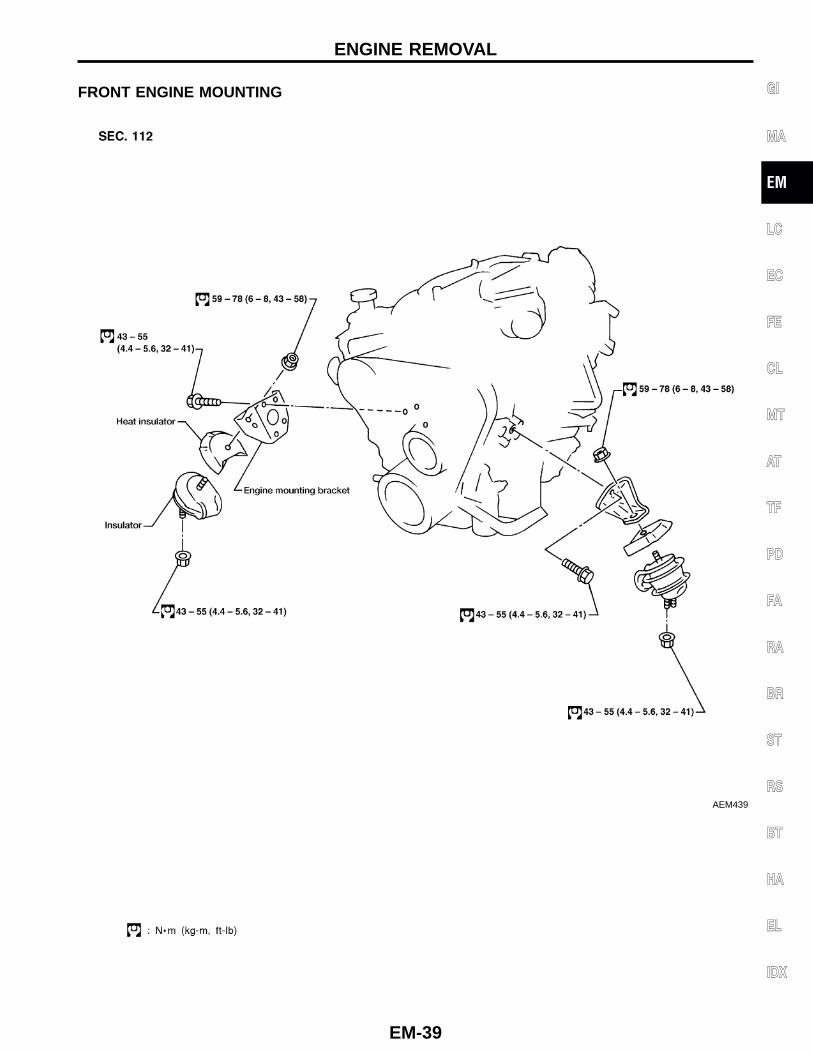
FRONT ENGINE MOUNTING
AEM439
GI
MA
EM
LC
EC
FE
CL
MT
AT
TF
PD
FA
RA
BR
ST
RS
BT
HA
EL
IDX
ENGINE REMOVAL
EM-39
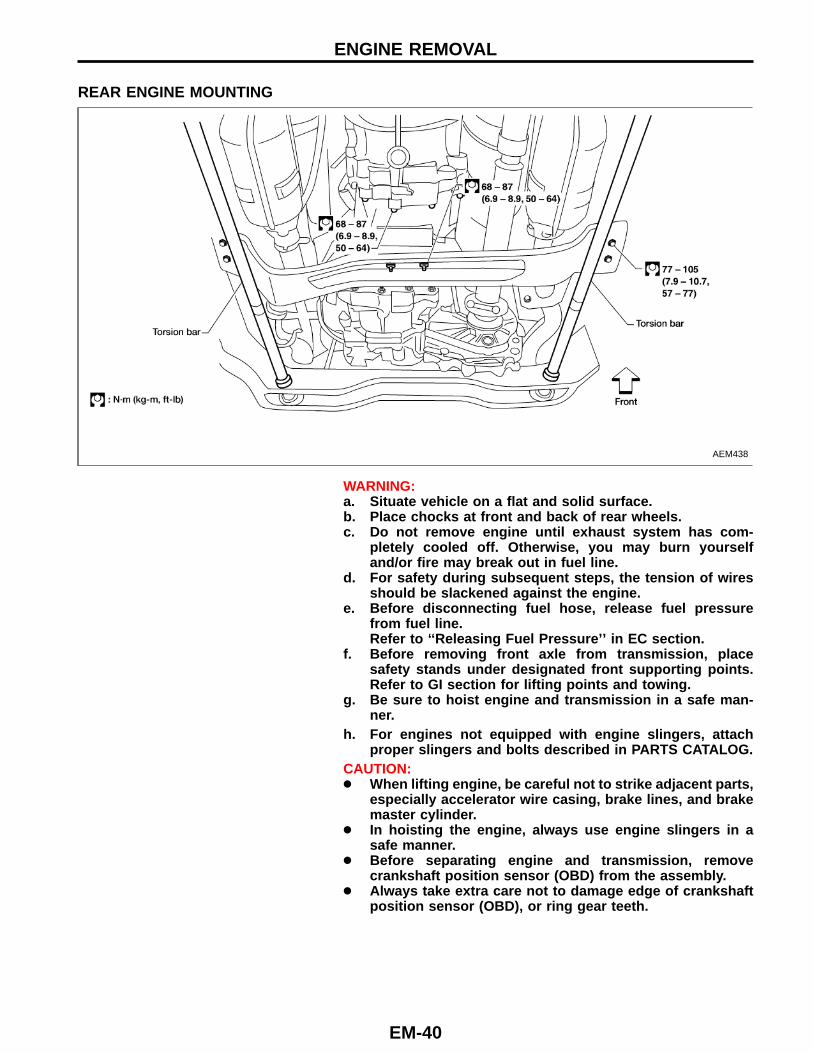
REAR ENGINE MOUNTING
AEM438
WARNING:a. Situate vehicle on a flat and solid surface.b. Place chocks at front and back of rear wheels.c. Do not remove engine until exhaust system has com-
pletely cooled off. Otherwise, you may burn yourselfand/or fire may break out in fuel line.
d. For safety during subsequent steps, the tension of wiresshould be slackened against the engine.
e. Before disconnecting fuel hose, release fuel pressurefrom fuel line.Refer to ‘‘Releasing Fuel Pressure ’’ in EC section.
f. Before removing front axle from transmission, placesafety stands under designated front supporting points.Refer to GI section for lifting points and towing.
g. Be sure to hoist engine and transmission in a safe man-ner.
h. For engines not equipped with engine slingers, attachproper slingers and bolts described in PARTS CATALOG.
CAUTION:● When lifting engine, be careful not to strike adjacent parts,
especially accelerator wire casing, brake lines, and brakemaster cylinder.
● In hoisting the engine, always use engine slingers in asafe manner.
● Before separating engine and transmission, removecrankshaft position sensor (OBD) from the assembly.
● Always take extra care not to damage edge of crankshaftposition sensor (OBD), or ring gear teeth.
ENGINE REMOVAL
EM-40
SEM322F
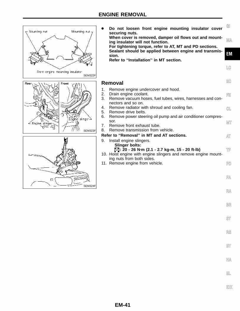
● Do not loosen front engine mounting insulator coversecuring nuts.When cover is removed, damper oil flows out and mount-ing insulator will not function.For tightening torque, refer to AT, MT and PD sections.Sealant should be applied between engine and transmis-sion.Refer to ‘‘Installation ’’ in MT section.
SEM323F
SEM324F
Removal1. Remove engine undercover and hood.2. Drain engine coolant.3. Remove vacuum hoses, fuel tubes, wires, harnesses and con-
nectors and so on.4. Remove radiator with shroud and cooling fan.5. Remove drive belts.6. Remove power steering oil pump and air conditioner compres-
sor.7. Remove front exhaust tube.8. Remove transmission from vehicle.Refer to ‘‘Removal ’’ in MT and AT sections.9. Install engine slingers.
Slinger bolts:: 20 - 26 N�m (2.1 - 2.7 kg-m, 15 - 20 ft-lb)
10. Hoist engine with engine slingers and remove engine mount-ing nuts from both sides.
11. Remove engine from vehicle.
GI
MA
EM
LC
EC
FE
CL
MT
AT
TF
PD
FA
RA
BR
ST
RS
BT
HA
EL
IDX
ENGINE REMOVAL
EM-41
SEM325FA
CYLINDER BLOCK
EM-42
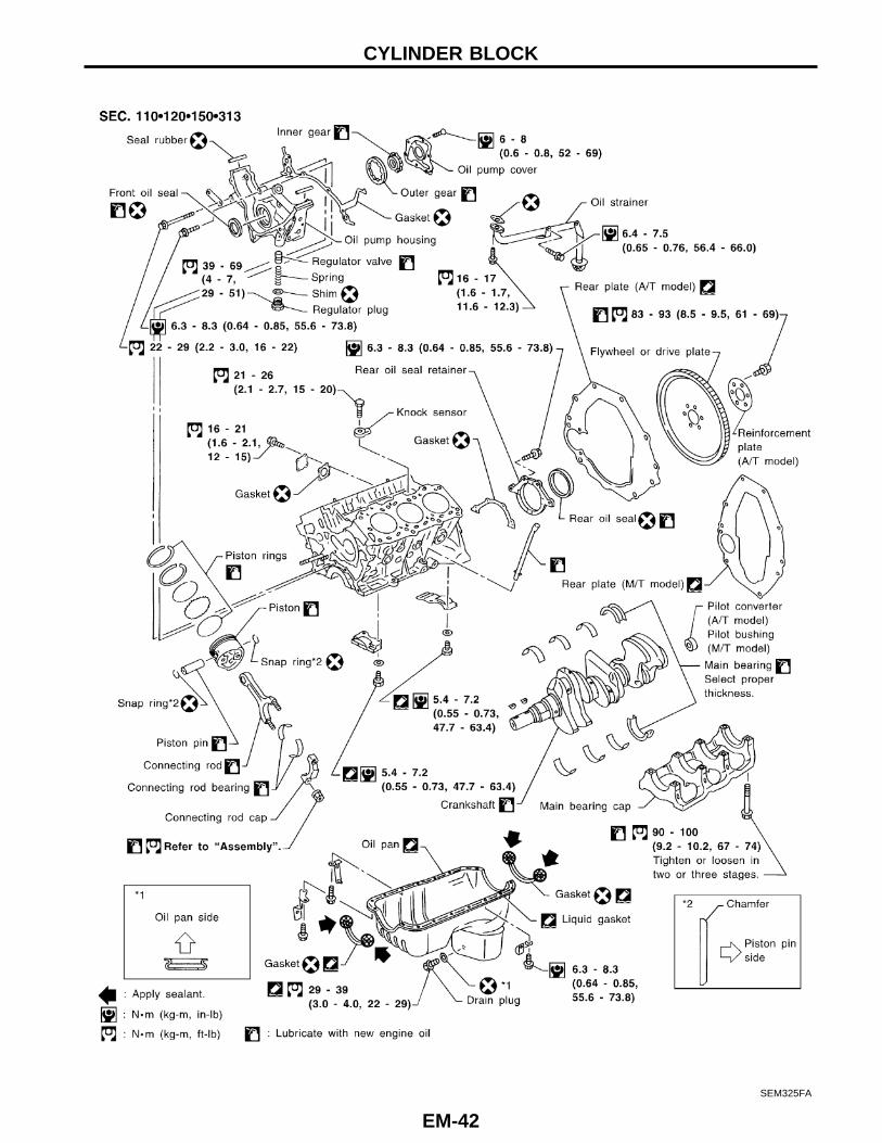
CAUTION:● When installing sliding parts such as bearings and
pistons, be sure to apply engine oil on the sliding sur-faces.
● Place removed parts such as bearings and bearing capsin their proper order and direction.
● When installing connecting rod bolts and main bearingcap bolts, apply new engine oil to threads and seatingsurfaces.
● Do not allow any magnetic materials to contact the ringgear teeth on flywheel or drive plate and rear plate.
SEM326FA
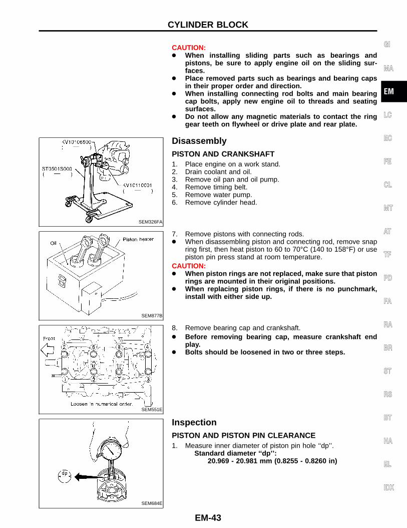
DisassemblyPISTON AND CRANKSHAFT1. Place engine on a work stand.2. Drain coolant and oil.3. Remove oil pan and oil pump.4. Remove timing belt.5. Remove water pump.6. Remove cylinder head.
SEM877B
7. Remove pistons with connecting rods.● When disassembling piston and connecting rod, remove snap
ring first, then heat piston to 60 to 70°C (140 to 158°F) or usepiston pin press stand at room temperature.
CAUTION:● When piston rings are not replaced, make sure that piston
rings are mounted in their original positions.● When replacing piston rings, if there is no punchmark,
install with either side up.
SEM551E
8. Remove bearing cap and crankshaft.● Before removing bearing cap, measure crankshaft end
play.● Bolts should be loosened in two or three steps.
SEM684E
InspectionPISTON AND PISTON PIN CLEARANCE1. Measure inner diameter of piston pin hole ‘‘dp’’.
Standard diameter ‘‘dp ’’:20.969 - 20.981 mm (0.8255 - 0.8260 in)
GI
MA
EM
LC
EC
FE
CL
MT
AT
TF
PD
FA
RA
BR
ST
RS
BT
HA
EL
IDX
CYLINDER BLOCK
EM-43
AEM024
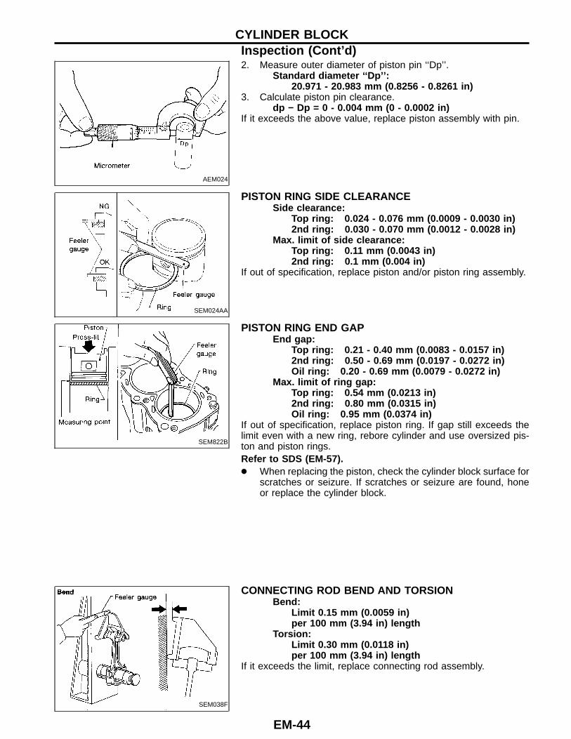
2. Measure outer diameter of piston pin ‘‘Dp’’.Standard diameter ‘‘Dp’’:
20.971 - 20.983 mm (0.8256 - 0.8261 in)3. Calculate piston pin clearance.
dp − Dp = 0 - 0.004 mm (0 - 0.0002 in)If it exceeds the above value, replace piston assembly with pin.
SEM024AA
PISTON RING SIDE CLEARANCESide clearance:
Top ring: 0.024 - 0.076 mm (0.0009 - 0.0030 in)2nd ring: 0.030 - 0.070 mm (0.0012 - 0.0028 in)
Max. limit of side clearance:Top ring: 0.11 mm (0.0043 in)2nd ring: 0.1 mm (0.004 in)
If out of specification, replace piston and/or piston ring assembly.
SEM822B
PISTON RING END GAPEnd gap:
Top ring: 0.21 - 0.40 mm (0.0083 - 0.0157 in)2nd ring: 0.50 - 0.69 mm (0.0197 - 0.0272 in)Oil ring: 0.20 - 0.69 mm (0.0079 - 0.0272 in)
Max. limit of ring gap:Top ring: 0.54 mm (0.0213 in)2nd ring: 0.80 mm (0.0315 in)Oil ring: 0.95 mm (0.0374 in)
If out of specification, replace piston ring. If gap still exceeds thelimit even with a new ring, rebore cylinder and use oversized pis-ton and piston rings.Refer to SDS (EM-57).● When replacing the piston, check the cylinder block surface for
scratches or seizure. If scratches or seizure are found, honeor replace the cylinder block.
SEM038F
CONNECTING ROD BEND AND TORSIONBend:
Limit 0.15 mm (0.0059 in)per 100 mm (3.94 in) length
Torsion:Limit 0.30 mm (0.0118 in)per 100 mm (3.94 in) length
If it exceeds the limit, replace connecting rod assembly.
CYLINDER BLOCKInspection (Cont’d)
EM-44
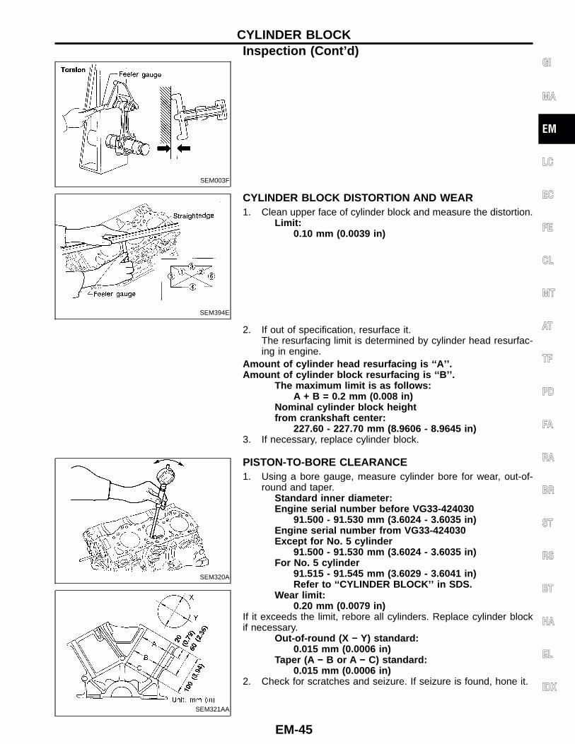
SEM003F
SEM394E
CYLINDER BLOCK DISTORTION AND WEAR1. Clean upper face of cylinder block and measure the distortion.
Limit:0.10 mm (0.0039 in)
2. If out of specification, resurface it.The resurfacing limit is determined by cylinder head resurfac-ing in engine.
Amount of cylinder head resurfacing is ‘‘A’’ .Amount of cylinder block resurfacing is ‘‘B’’ .
The maximum limit is as follows:A + B = 0.2 mm (0.008 in)
Nominal cylinder block heightfrom crankshaft center:
227.60 - 227.70 mm (8.9606 - 8.9645 in)3. If necessary, replace cylinder block.
SEM320A
SEM321AA
PISTON-TO-BORE CLEARANCE1. Using a bore gauge, measure cylinder bore for wear, out-of-
round and taper.Standard inner diameter:Engine serial number before VG33-424030
91.500 - 91.530 mm (3.6024 - 3.6035 in)Engine serial number from VG33-424030Except for No. 5 cylinder
91.500 - 91.530 mm (3.6024 - 3.6035 in)For No. 5 cylinder
91.515 - 91.545 mm (3.6029 - 3.6041 in)Refer to ‘‘CYLINDER BLOCK’’ in SDS.
Wear limit:0.20 mm (0.0079 in)
If it exceeds the limit, rebore all cylinders. Replace cylinder blockif necessary.
Out-of-round (X − Y) standard:0.015 mm (0.0006 in)
Taper (A − B or A − C) standard:0.015 mm (0.0006 in)
2. Check for scratches and seizure. If seizure is found, hone it.
GI
MA
EM
LC
EC
FE
CL
MT
AT
TF
PD
FA
RA
BR
ST
RS
BT
HA
EL
IDX
CYLINDER BLOCKInspection (Cont’d)
EM-45
SEM557AA
SEM399F
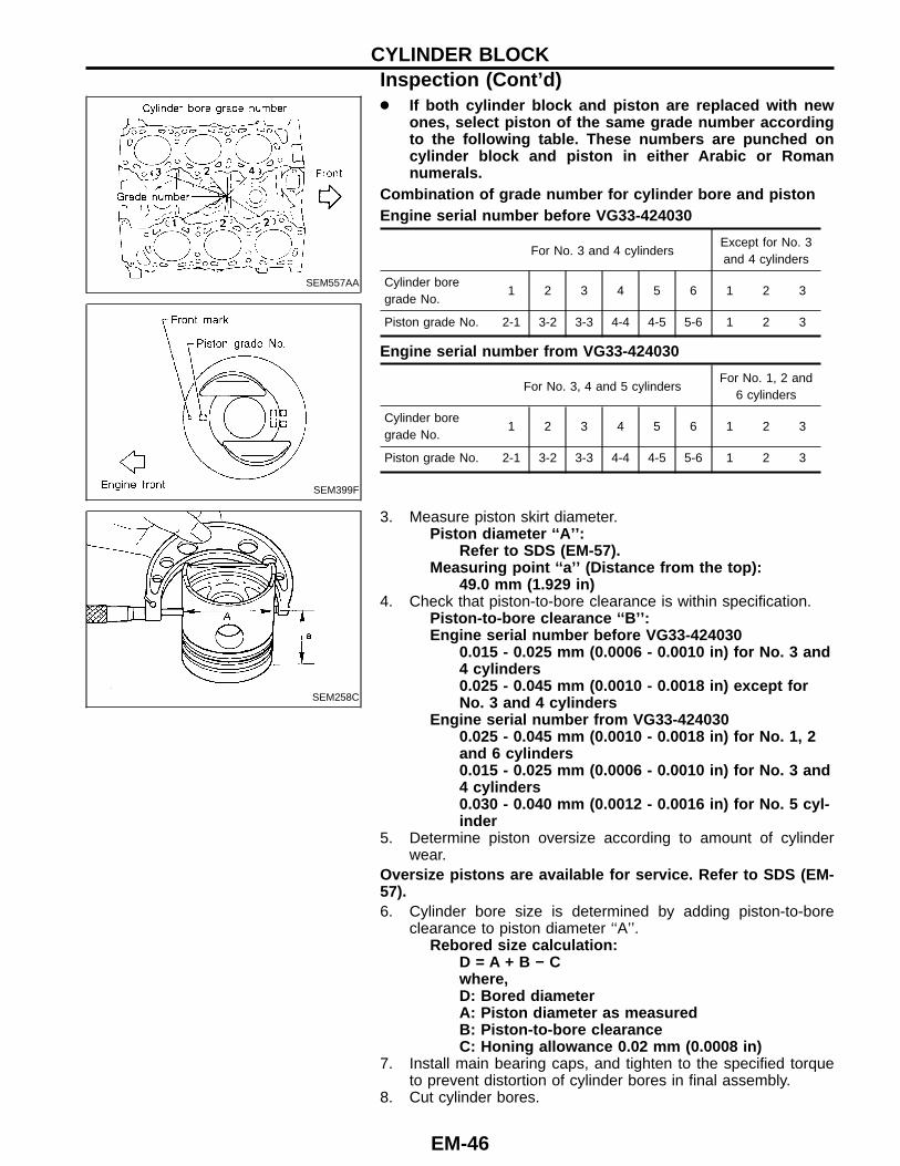
● If both cylinder block and piston are replaced with newones, select piston of the same grade number accordingto the following table. These numbers are punched oncylinder block and piston in either Arabic or Romannumerals.
Combination of grade number for cylinder bore and pistonEngine serial number before VG33-424030
For No. 3 and 4 cylindersExcept for No. 3and 4 cylinders
Cylinder boregrade No.
1 2 3 4 5 6 1 2 3
Piston grade No. 2-1 3-2 3-3 4-4 4-5 5-6 1 2 3
Engine serial number from VG33-424030
For No. 3, 4 and 5 cylindersFor No. 1, 2 and
6 cylinders
Cylinder boregrade No.
1 2 3 4 5 6 1 2 3
Piston grade No. 2-1 3-2 3-3 4-4 4-5 5-6 1 2 3
SEM258C
3. Measure piston skirt diameter.Piston diameter ‘‘A’’ :
Refer to SDS (EM-57).Measuring point ‘‘a’’ (Distance from the top):
49.0 mm (1.929 in)4. Check that piston-to-bore clearance is within specification.
Piston-to-bore clearance ‘‘B’’ :Engine serial number before VG33-424030
0.015 - 0.025 mm (0.0006 - 0.0010 in) for No. 3 and4 cylinders0.025 - 0.045 mm (0.0010 - 0.0018 in) except forNo. 3 and 4 cylinders
Engine serial number from VG33-4240300.025 - 0.045 mm (0.0010 - 0.0018 in) for No. 1, 2and 6 cylinders0.015 - 0.025 mm (0.0006 - 0.0010 in) for No. 3 and4 cylinders0.030 - 0.040 mm (0.0012 - 0.0016 in) for No. 5 cyl-inder
5. Determine piston oversize according to amount of cylinderwear.
Oversize pistons are available for service. Refer to SDS (EM-57).6. Cylinder bore size is determined by adding piston-to-bore
clearance to piston diameter ‘‘A’’.Rebored size calculation:
D = A + B − Cwhere,D: Bored diameterA: Piston diameter as measuredB: Piston-to-bore clearanceC: Honing allowance 0.02 mm (0.0008 in)
7. Install main bearing caps, and tighten to the specified torqueto prevent distortion of cylinder bores in final assembly.
8. Cut cylinder bores.
CYLINDER BLOCKInspection (Cont’d)
EM-46
● When any cylinder needs boring, all other cylinders mustalso be bored.
● Do not cut too much out of cylinder bore at a time. Cutonly 0.05 mm (0.0020 in) or so in diameter at a time.
9. Hone cylinders to obtain specified piston-to-bore clearance.10. Measure finished cylinder bore for out-of-round and taper.● Measurement should be done after cylinder bore cools
down.
SEM316A
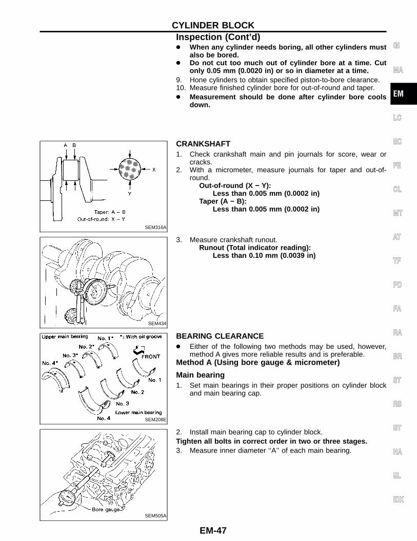
CRANKSHAFT1. Check crankshaft main and pin journals for score, wear or
cracks.2. With a micrometer, measure journals for taper and out-of-
round.Out-of-round (X − Y):
Less than 0.005 mm (0.0002 in)Taper (A − B):
Less than 0.005 mm (0.0002 in)
SEM434
3. Measure crankshaft runout.Runout (Total indicator reading):
Less than 0.10 mm (0.0039 in)
SEM208E
BEARING CLEARANCE● Either of the following two methods may be used, however,
method A gives more reliable results and is preferable.Method A (Using bore gauge & micrometer)
Main bearing1. Set main bearings in their proper positions on cylinder block
and main bearing cap.
SEM505A
2. Install main bearing cap to cylinder block.Tighten all bolts in correct order in two or three stages.3. Measure inner diameter ‘‘A’’ of each main bearing.
GI
MA
EM
LC
EC
FE
CL
MT
AT
TF
PD
FA
RA
BR
ST
RS
BT
HA
EL
IDX
CYLINDER BLOCKInspection (Cont’d)
EM-47
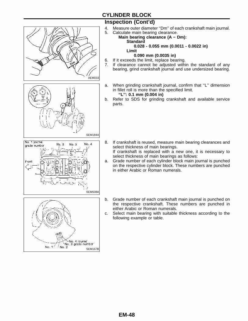
AEM033
4. Measure outer diameter ‘‘Dm’’ of each crankshaft main journal.5. Calculate main bearing clearance.
Main bearing clearance (A − Dm):Standard
0.028 - 0.055 mm (0.0011 - 0.0022 in)Limit
0.090 mm (0.0035 in)6. If it exceeds the limit, replace bearing.7. If clearance cannot be adjusted within the standard of any
bearing, grind crankshaft journal and use undersized bearing.
SEM184A
a. When grinding crankshaft journal, confirm that ‘‘L’’ dimensionin fillet roll is more than the specified limit.
‘‘L’’ : 0.1 mm (0.004 in)b. Refer to SDS for grinding crankshaft and available service
parts.
SEM508A
8. If crankshaft is reused, measure main bearing clearances andselect thickness of main bearings.If crankshaft is replaced with a new one, it is necessary toselect thickness of main bearings as follows:
a. Grade number of each cylinder block main journal is punchedon the respective cylinder block. These numbers are punchedin either Arabic or Roman numerals.
SEM167B
b. Grade number of each crankshaft main journal is punched onthe respective crankshaft. These numbers are punched ineither Arabic or Roman numerals.
c. Select main bearing with suitable thickness according to thefollowing example or table.
CYLINDER BLOCKInspection (Cont’d)
EM-48
Main bearing grade numberNo. 1 main bearing(Identification color):
Crank shaftmain journalgrade number
Cylinder block main journal grade number
3 4 5 6
3 A (Black) B (Brown) C (Green) D (Yellow)
4 B (Brown) C (Green) D (Yellow) E (Blue)
5 C (Green) D (Yellow) E (Blue) F (Pink)
6 D (Yellow) E (Blue) F (Pink) G (Purple)
No. 2, 3 and No. 4 main bearings(Identification color):
Main journal grade number
0 1 2
Crankshaftjournal gradenumber
0 A (Black) B (Brown) D (Green)
1 B (Brown) D (Green) E (Yellow)
2 C (Green) E (Yellow) F (Blue)
AEM027
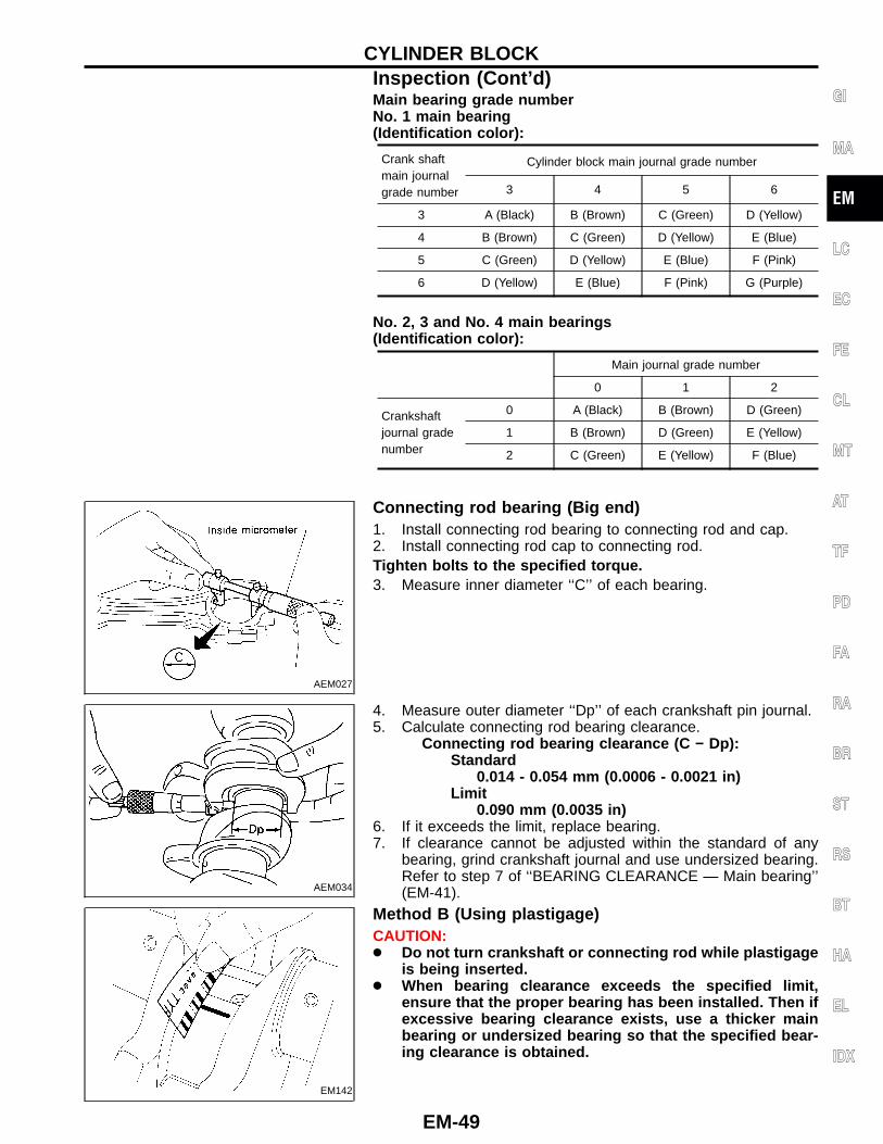
Connecting rod bearing (Big end)1. Install connecting rod bearing to connecting rod and cap.2. Install connecting rod cap to connecting rod.Tighten bolts to the specified torque.3. Measure inner diameter ‘‘C’’ of each bearing.
AEM034
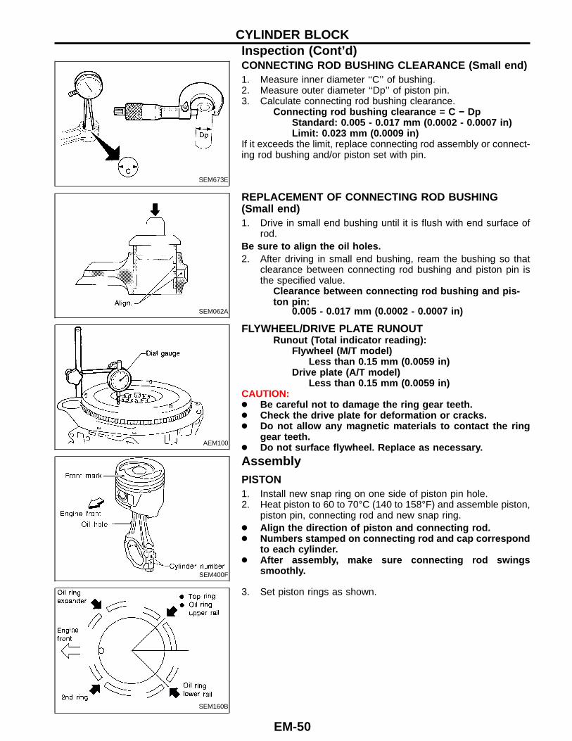
4. Measure outer diameter ‘‘Dp’’ of each crankshaft pin journal.5. Calculate connecting rod bearing clearance.
Connecting rod bearing clearance (C − Dp):Standard
0.014 - 0.054 mm (0.0006 - 0.0021 in)Limit
0.090 mm (0.0035 in)6. If it exceeds the limit, replace bearing.7. If clearance cannot be adjusted within the standard of any
bearing, grind crankshaft journal and use undersized bearing.Refer to step 7 of ‘‘BEARING CLEARANCE — Main bearing’’(EM-41).
EM142
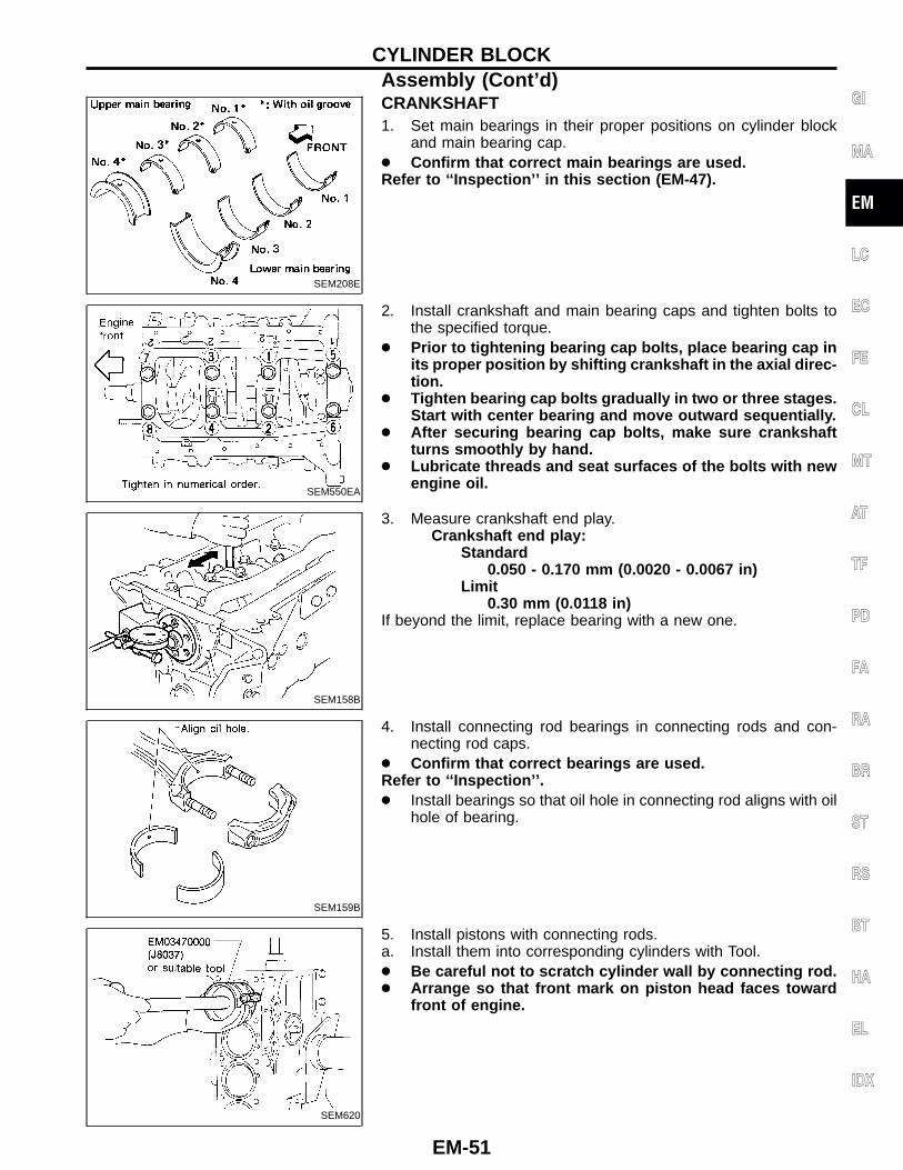
Method B (Using plastigage)CAUTION:● Do not turn crankshaft or connecting rod while plastigage
is being inserted.● When bearing clearance exceeds the specified limit,
ensure that the proper bearing has been installed. Then ifexcessive bearing clearance exists, use a thicker mainbearing or undersized bearing so that the specified bear-ing clearance is obtained.
GI
MA
EM
LC
EC
FE
CL
MT
AT
TF
PD
FA
RA
BR
ST
RS
BT
HA
EL
IDX
CYLINDER BLOCKInspection (Cont’d)
EM-49
SEM673E
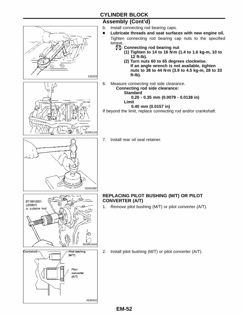
CONNECTING ROD BUSHING CLEARANCE (Small end)1. Measure inner diameter ‘‘C’’ of bushing.2. Measure outer diameter ‘‘Dp’’ of piston pin.3. Calculate connecting rod bushing clearance.
Connecting rod bushing clearance = C − DpStandard: 0.005 - 0.017 mm (0.0002 - 0.0007 in)Limit: 0.023 mm (0.0009 in)
If it exceeds the limit, replace connecting rod assembly or connect-ing rod bushing and/or piston set with pin.
SEM062A
REPLACEMENT OF CONNECTING ROD BUSHING(Small end)1. Drive in small end bushing until it is flush with end surface of
rod.Be sure to align the oil holes.2. After driving in small end bushing, ream the bushing so that
clearance between connecting rod bushing and piston pin isthe specified value.
Clearance between connecting rod bushing and pis-ton pin:
0.005 - 0.017 mm (0.0002 - 0.0007 in)
AEM100
FLYWHEEL/DRIVE PLATE RUNOUTRunout (Total indicator reading):
Flywheel (M/T model)Less than 0.15 mm (0.0059 in)
Drive plate (A/T model)Less than 0.15 mm (0.0059 in)
CAUTION:● Be careful not to damage the ring gear teeth.● Check the drive plate for deformation or cracks.● Do not allow any magnetic materials to contact the ring
gear teeth.● Do not surface flywheel. Replace as necessary.
SEM400F
AssemblyPISTON1. Install new snap ring on one side of piston pin hole.2. Heat piston to 60 to 70°C (140 to 158°F) and assemble piston,
piston pin, connecting rod and new snap ring.● Align the direction of piston and connecting rod.● Numbers stamped on connecting rod and cap correspond
to each cylinder.● After assembly, make sure connecting rod swings
smoothly.
SEM160B
3. Set piston rings as shown.
CYLINDER BLOCKInspection (Cont’d)
EM-50
SEM208E
CRANKSHAFT1. Set main bearings in their proper positions on cylinder block
and main bearing cap.● Confirm that correct main bearings are used.Refer to ‘‘ Inspection’’ in this section (EM-47).
SEM550EA
2. Install crankshaft and main bearing caps and tighten bolts tothe specified torque.
● Prior to tightening bearing cap bolts, place bearing cap inits proper position by shifting crankshaft in the axial direc-tion.
● Tighten bearing cap bolts gradually in two or three stages.Start with center bearing and move outward sequentially.
● After securing bearing cap bolts, make sure crankshaftturns smoothly by hand.
● Lubricate threads and seat surfaces of the bolts with newengine oil.
SEM158B
3. Measure crankshaft end play.Crankshaft end play:
Standard0.050 - 0.170 mm (0.0020 - 0.0067 in)
Limit0.30 mm (0.0118 in)
If beyond the limit, replace bearing with a new one.
SEM159B
4. Install connecting rod bearings in connecting rods and con-necting rod caps.
● Confirm that correct bearings are used.Refer to ‘‘ Inspection’’ .● Install bearings so that oil hole in connecting rod aligns with oil
hole of bearing.
SEM620
5. Install pistons with connecting rods.a. Install them into corresponding cylinders with Tool.● Be careful not to scratch cylinder wall by connecting rod.● Arrange so that front mark on piston head faces toward
front of engine.
GI
MA
EM
LC
EC
FE
CL
MT
AT
TF
PD
FA
RA
BR
ST
RS
BT
HA
EL
IDX
CYLINDER BLOCKAssembly (Cont’d)
EM-51
EM329
b. Install connecting rod bearing caps.● Lubricate threads and seat surfaces with new engine oil.
Tighten connecting rod bearing cap nuts to the specifiedtorque.
: Connecting rod bearing nut(1) Tighten to 14 to 16 N�m (1.4 to 1.6 kg-m, 10 to
12 ft-lb).(2) Turn nuts 60 to 65 degrees clockwise.
If an angle wrench is not available, tightennuts to 38 to 44 N�m (3.9 to 4.5 kg-m, 28 to 33ft-lb).
SEM512A
6. Measure connecting rod side clearance.Connecting rod side clearance:
Standard0.20 - 0.35 mm (0.0079 - 0.0138 in)
Limit0.40 mm (0.0157 in)
If beyond the limit, replace connecting rod and/or crankshaft.
SEM338F
7. Install rear oil seal retainer.
SEM916AA
REPLACING PILOT BUSHING (M/T) OR PILOTCONVERTER (A/T)1. Remove pilot bushing (M/T) or pilot converter (A/T).
AEM402
2. Install pilot bushing (M/T) or pilot converter (A/T).
CYLINDER BLOCKAssembly (Cont’d)
EM-52
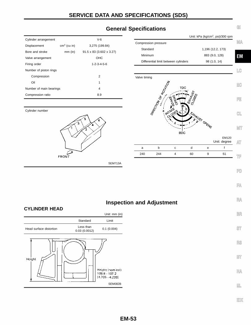
General Specifications
Cylinder arrangement V-6
Displacement cm3 (cu in) 3,275 (199.84)
Bore and stroke mm (in) 91.5 x 83 (3.602 x 3.27)
Valve arrangement OHC
Firing order 1-2-3-4-5-6
Number of piston rings
Compression 2
Oil 1
Number of main bearings 4
Compression ratio 8.9
Cylinder number
SEM713A
Unit: kPa (kg/cm2, psi)/300 rpm
Compression pressure
Standard 1,196 (12.2, 173)
Minimum 883 (9.0, 128)
Differential limit between cylinders 98 (1.0, 14)
Valve timing
EM120Unit: degree
a b c d e f
240 244 4 60 9 51
Inspection and AdjustmentCYLINDER HEAD
Unit: mm (in)
Standard Limit
Head surface distortionLess than
0.03 (0.0012)0.1 (0.004)
SEM082B
GI
MA
EM
LC
EC
FE
CL
MT
AT
TF
PD
FA
RA
BR
ST
RS
BT
HA
EL
IDX
SERVICE DATA AND SPECIFICATIONS (SDS)
EM-53
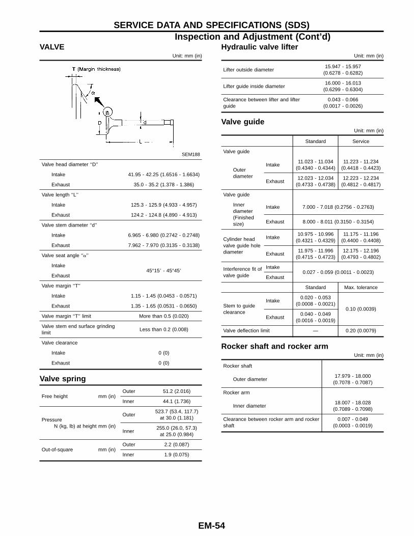
VALVEUnit: mm (in)
SEM188
Valve head diameter ‘‘D’’
Intake 41.95 - 42.25 (1.6516 - 1.6634)
Exhaust 35.0 - 35.2 (1.378 - 1.386)
Valve length ‘‘L’’
Intake 125.3 - 125.9 (4.933 - 4.957)
Exhaust 124.2 - 124.8 (4.890 - 4.913)
Valve stem diameter ‘‘d’’
Intake 6.965 - 6.980 (0.2742 - 0.2748)
Exhaust 7.962 - 7.970 (0.3135 - 0.3138)
Valve seat angle ‘‘�’’
Intake45°15� - 45°45�
Exhaust
Valve margin ‘‘T’’
Intake 1.15 - 1.45 (0.0453 - 0.0571)
Exhaust 1.35 - 1.65 (0.0531 - 0.0650)
Valve margin ‘‘T’’ limit More than 0.5 (0.020)
Valve stem end surface grindinglimit
Less than 0.2 (0.008)
Valve clearance
Intake 0 (0)
Exhaust 0 (0)
Valve spring
Free height mm (in)Outer 51.2 (2.016)
Inner 44.1 (1.736)
PressureN (kg, lb) at height mm (in)
Outer523.7 (53.4, 117.7)
at 30.0 (1.181)
Inner255.0 (26.0, 57.3)
at 25.0 (0.984)
Out-of-square mm (in)Outer 2.2 (0.087)
Inner 1.9 (0.075)
Hydraulic valve lifterUnit: mm (in)
Lifter outside diameter15.947 - 15.957
(0.6278 - 0.6282)
Lifter guide inside diameter16.000 - 16.013
(0.6299 - 0.6304)
Clearance between lifter and lifterguide
0.043 - 0.066(0.0017 - 0.0026)
Valve guideUnit: mm (in)
Standard Service
Valve guide
Outerdiameter
Intake11.023 - 11.034
(0.4340 - 0.4344)11.223 - 11.234
(0.4418 - 0.4423)
Exhaust12.023 - 12.034
(0.4733 - 0.4738)12.223 - 12.234
(0.4812 - 0.4817)
Valve guide
Innerdiameter(Finishedsize)
Intake 7.000 - 7.018 (0.2756 - 0.2763)
Exhaust 8.000 - 8.011 (0.3150 - 0.3154)
Cylinder headvalve guide holediameter
Intake10.975 - 10.996
(0.4321 - 0.4329)11.175 - 11.196
(0.4400 - 0.4408)
Exhaust11.975 - 11.996
(0.4715 - 0.4723)12.175 - 12.196
(0.4793 - 0.4802)
Interference fit ofvalve guide
Intake0.027 - 0.059 (0.0011 - 0.0023)
Exhaust
Standard Max. tolerance
Stem to guideclearance
Intake0.020 - 0.053
(0.0008 - 0.0021)0.10 (0.0039)
Exhaust0.040 - 0.049
(0.0016 - 0.0019)
Valve deflection limit — 0.20 (0.0079)
Rocker shaft and rocker armUnit: mm (in)
Rocker shaft
Outer diameter17.979 - 18.000
(0.7078 - 0.7087)
Rocker arm
Inner diameter18.007 - 18.028
(0.7089 - 0.7098)
Clearance between rocker arm and rockershaft
0.007 - 0.049(0.0003 - 0.0019)
SERVICE DATA AND SPECIFICATIONS (SDS)Inspection and Adjustment (Cont’d)
EM-54
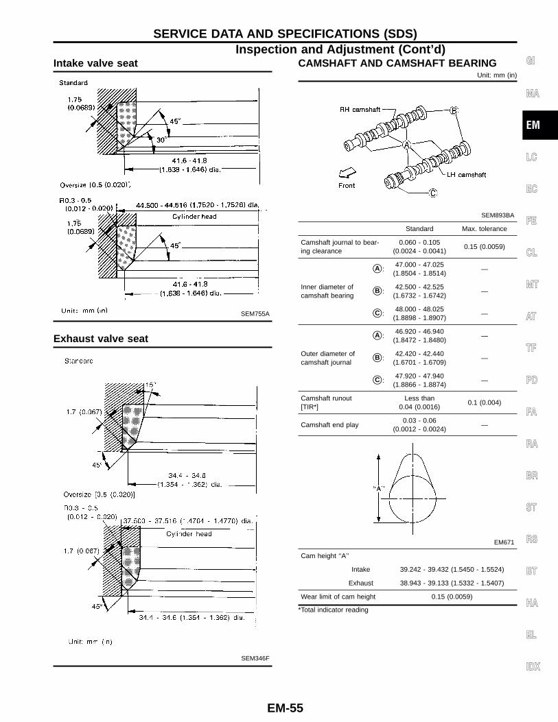
Intake valve seat
SEM755A
Exhaust valve seat
SEM346F
CAMSHAFT AND CAMSHAFT BEARINGUnit: mm (in)
SEM893BA
Standard Max. tolerance
Camshaft journal to bear-ing clearance
0.060 - 0.105(0.0024 - 0.0041)
0.15 (0.0059)
Inner diameter ofcamshaft bearing
�A :47.000 - 47.025
(1.8504 - 1.8514)—
�B :42.500 - 42.525
(1.6732 - 1.6742)—
�C :48.000 - 48.025
(1.8898 - 1.8907)—
Outer diameter ofcamshaft journal
�A :46.920 - 46.940
(1.8472 - 1.8480)—
�B :42.420 - 42.440
(1.6701 - 1.6709)—
�C :47.920 - 47.940
(1.8866 - 1.8874)—
Camshaft runout[TIR*]
Less than0.04 (0.0016)
0.1 (0.004)
Camshaft end play0.03 - 0.06
(0.0012 - 0.0024)—
EM671
Cam height ‘‘A’’
Intake 39.242 - 39.432 (1.5450 - 1.5524)
Exhaust 38.943 - 39.133 (1.5332 - 1.5407)
Wear limit of cam height 0.15 (0.0059)
*Total indicator reading
GI
MA
EM
LC
EC
FE
CL
MT
AT
TF
PD
FA
RA
BR
ST
RS
BT
HA
EL
IDX
SERVICE DATA AND SPECIFICATIONS (SDS)Inspection and Adjustment (Cont’d)
EM-55
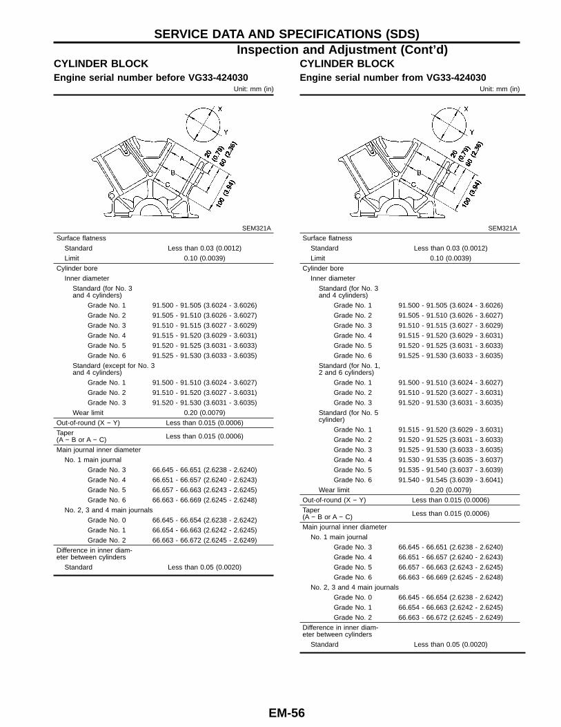
CYLINDER BLOCKEngine serial number before VG33-424030
Unit: mm (in)
SEM321A
Surface flatness
Standard Less than 0.03 (0.0012)
Limit 0.10 (0.0039)
Cylinder bore
Inner diameter
Standard (for No. 3and 4 cylinders)
Grade No. 1 91.500 - 91.505 (3.6024 - 3.6026)
Grade No. 2 91.505 - 91.510 (3.6026 - 3.6027)
Grade No. 3 91.510 - 91.515 (3.6027 - 3.6029)
Grade No. 4 91.515 - 91.520 (3.6029 - 3.6031)
Grade No. 5 91.520 - 91.525 (3.6031 - 3.6033)
Grade No. 6 91.525 - 91.530 (3.6033 - 3.6035)
Standard (except for No. 3and 4 cylinders)
Grade No. 1 91.500 - 91.510 (3.6024 - 3.6027)
Grade No. 2 91.510 - 91.520 (3.6027 - 3.6031)
Grade No. 3 91.520 - 91.530 (3.6031 - 3.6035)
Wear limit 0.20 (0.0079)
Out-of-round (X − Y) Less than 0.015 (0.0006)
Taper(A − B or A − C) Less than 0.015 (0.0006)
Main journal inner diameter
No. 1 main journal
Grade No. 3 66.645 - 66.651 (2.6238 - 2.6240)
Grade No. 4 66.651 - 66.657 (2.6240 - 2.6243)
Grade No. 5 66.657 - 66.663 (2.6243 - 2.6245)
Grade No. 6 66.663 - 66.669 (2.6245 - 2.6248)
No. 2, 3 and 4 main journals
Grade No. 0 66.645 - 66.654 (2.6238 - 2.6242)
Grade No. 1 66.654 - 66.663 (2.6242 - 2.6245)
Grade No. 2 66.663 - 66.672 (2.6245 - 2.6249)
Difference in inner diam-eter between cylinders
Standard Less than 0.05 (0.0020)
CYLINDER BLOCKEngine serial number from VG33-424030
Unit: mm (in)
SEM321A
Surface flatness
Standard Less than 0.03 (0.0012)
Limit 0.10 (0.0039)
Cylinder bore
Inner diameter
Standard (for No. 3and 4 cylinders)
Grade No. 1 91.500 - 91.505 (3.6024 - 3.6026)
Grade No. 2 91.505 - 91.510 (3.6026 - 3.6027)
Grade No. 3 91.510 - 91.515 (3.6027 - 3.6029)
Grade No. 4 91.515 - 91.520 (3.6029 - 3.6031)
Grade No. 5 91.520 - 91.525 (3.6031 - 3.6033)
Grade No. 6 91.525 - 91.530 (3.6033 - 3.6035)
Standard (for No. 1,2 and 6 cylinders)
Grade No. 1 91.500 - 91.510 (3.6024 - 3.6027)
Grade No. 2 91.510 - 91.520 (3.6027 - 3.6031)
Grade No. 3 91.520 - 91.530 (3.6031 - 3.6035)
Standard (for No. 5cylinder)
Grade No. 1 91.515 - 91.520 (3.6029 - 3.6031)
Grade No. 2 91.520 - 91.525 (3.6031 - 3.6033)
Grade No. 3 91.525 - 91.530 (3.6033 - 3.6035)
Grade No. 4 91.530 - 91.535 (3.6035 - 3.6037)
Grade No. 5 91.535 - 91.540 (3.6037 - 3.6039)
Grade No. 6 91.540 - 91.545 (3.6039 - 3.6041)
Wear limit 0.20 (0.0079)
Out-of-round (X − Y) Less than 0.015 (0.0006)
Taper(A − B or A − C) Less than 0.015 (0.0006)
Main journal inner diameter
No. 1 main journal
Grade No. 3 66.645 - 66.651 (2.6238 - 2.6240)
Grade No. 4 66.651 - 66.657 (2.6240 - 2.6243)
Grade No. 5 66.657 - 66.663 (2.6243 - 2.6245)
Grade No. 6 66.663 - 66.669 (2.6245 - 2.6248)
No. 2, 3 and 4 main journals
Grade No. 0 66.645 - 66.654 (2.6238 - 2.6242)
Grade No. 1 66.654 - 66.663 (2.6242 - 2.6245)
Grade No. 2 66.663 - 66.672 (2.6245 - 2.6249)
Difference in inner diam-eter between cylinders
Standard Less than 0.05 (0.0020)
SERVICE DATA AND SPECIFICATIONS (SDS)Inspection and Adjustment (Cont’d)
EM-56
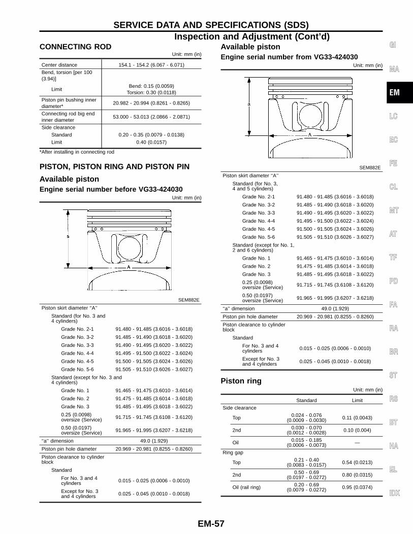
CONNECTING RODUnit: mm (in)
Center distance 154.1 - 154.2 (6.067 - 6.071)
Bend, torsion [per 100(3.94)]
LimitBend: 0.15 (0.0059)
Torsion: 0.30 (0.0118)
Piston pin bushing innerdiameter*
20.982 - 20.994 (0.8261 - 0.8265)
Connecting rod big endinner diameter
53.000 - 53.013 (2.0866 - 2.0871)
Side clearance
Standard 0.20 - 0.35 (0.0079 - 0.0138)
Limit 0.40 (0.0157)
*After installing in connecting rod
PISTON, PISTON RING AND PISTON PIN
Available pistonEngine serial number before VG33-424030
Unit: mm (in)
SEM882E
Piston skirt diameter ‘‘A’’
Standard (for No. 3 and4 cylinders)
Grade No. 2-1 91.480 - 91.485 (3.6016 - 3.6018)
Grade No. 3-2 91.485 - 91.490 (3.6018 - 3.6020)
Grade No. 3-3 91.490 - 91.495 (3.6020 - 3.6022)
Grade No. 4-4 91.495 - 91.500 (3.6022 - 3.6024)
Grade No. 4-5 91.500 - 91.505 (3.6024 - 3.6026)
Grade No. 5-6 91.505 - 91.510 (3.6026 - 3.6027)
Standard (except for No. 3 and4 cylinders)
Grade No. 1 91.465 - 91.475 (3.6010 - 3.6014)
Grade No. 2 91.475 - 91.485 (3.6014 - 3.6018)
Grade No. 3 91.485 - 91.495 (3.6018 - 3.6022)
0.25 (0.0098)oversize (Service) 91.715 - 91.745 (3.6108 - 3.6120)
0.50 (0.0197)oversize (Service) 91.965 - 91.995 (3.6207 - 3.6218)
‘‘a’’ dimension 49.0 (1.929)
Piston pin hole diameter 20.969 - 20.981 (0.8255 - 0.8260)
Piston clearance to cylinderblock
Standard
For No. 3 and 4cylinders 0.015 - 0.025 (0.0006 - 0.0010)
Except for No. 3and 4 cylinders 0.025 - 0.045 (0.0010 - 0.0018)
Available pistonEngine serial number from VG33-424030
Unit: mm (in)
SEM882E
Piston skirt diameter ‘‘A’’
Standard (for No. 3,4 and 5 cylinders)
Grade No. 2-1 91.480 - 91.485 (3.6016 - 3.6018)
Grade No. 3-2 91.485 - 91.490 (3.6018 - 3.6020)
Grade No. 3-3 91.490 - 91.495 (3.6020 - 3.6022)
Grade No. 4-4 91.495 - 91.500 (3.6022 - 3.6024)
Grade No. 4-5 91.500 - 91.505 (3.6024 - 3.6026)
Grade No. 5-6 91.505 - 91.510 (3.6026 - 3.6027)
Standard (except for No. 1,2 and 6 cylinders)
Grade No. 1 91.465 - 91.475 (3.6010 - 3.6014)
Grade No. 2 91.475 - 91.485 (3.6014 - 3.6018)
Grade No. 3 91.485 - 91.495 (3.6018 - 3.6022)
0.25 (0.0098)oversize (Service) 91.715 - 91.745 (3.6108 - 3.6120)
0.50 (0.0197)oversize (Service) 91.965 - 91.995 (3.6207 - 3.6218)
‘‘a’’ dimension 49.0 (1.929)
Piston pin hole diameter 20.969 - 20.981 (0.8255 - 0.8260)
Piston clearance to cylinderblock
Standard
For No. 3 and 4cylinders 0.015 - 0.025 (0.0006 - 0.0010)
Except for No. 3and 4 cylinders 0.025 - 0.045 (0.0010 - 0.0018)
Piston ringUnit: mm (in)
Standard Limit
Side clearance
Top 0.024 - 0.076(0.0009 - 0.0030) 0.11 (0.0043)
2nd 0.030 - 0.070(0.0012 - 0.0028) 0.10 (0.004)
Oil 0.015 - 0.185(0.0006 - 0.0073) —
Ring gap
Top 0.21 - 0.40(0.0083 - 0.0157) 0.54 (0.0213)
2nd 0.50 - 0.69(0.0197 - 0.0272) 0.80 (0.0315)
Oil (rail ring) 0.20 - 0.69(0.0079 - 0.0272) 0.95 (0.0374)
GI
MA
EM
LC
EC
FE
CL
MT
AT
TF
PD
FA
RA
BR
ST
RS
BT
HA
EL
IDX
SERVICE DATA AND SPECIFICATIONS (SDS)Inspection and Adjustment (Cont’d)
EM-57
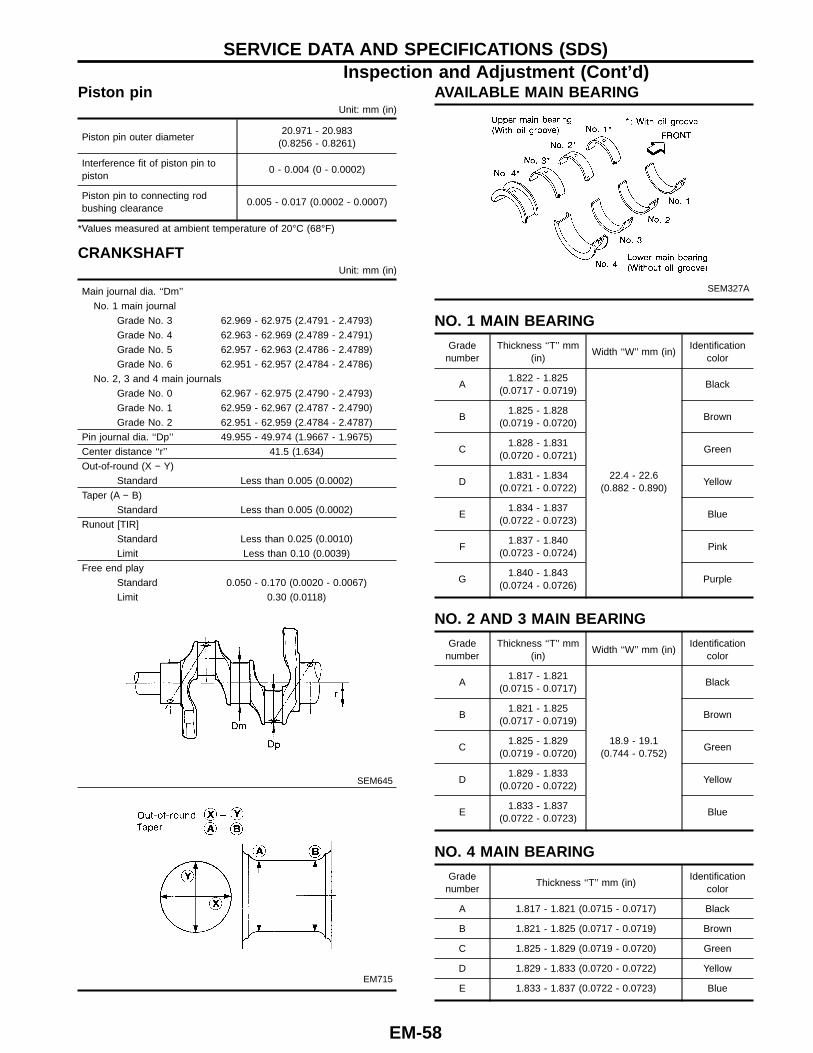
Piston pinUnit: mm (in)
Piston pin outer diameter20.971 - 20.983
(0.8256 - 0.8261)
Interference fit of piston pin topiston
0 - 0.004 (0 - 0.0002)
Piston pin to connecting rodbushing clearance
0.005 - 0.017 (0.0002 - 0.0007)
*Values measured at ambient temperature of 20°C (68°F)
CRANKSHAFTUnit: mm (in)
Main journal dia. ‘‘Dm’’
No. 1 main journal
Grade No. 3 62.969 - 62.975 (2.4791 - 2.4793)
Grade No. 4 62.963 - 62.969 (2.4789 - 2.4791)
Grade No. 5 62.957 - 62.963 (2.4786 - 2.4789)
Grade No. 6 62.951 - 62.957 (2.4784 - 2.4786)
No. 2, 3 and 4 main journals
Grade No. 0 62.967 - 62.975 (2.4790 - 2.4793)
Grade No. 1 62.959 - 62.967 (2.4787 - 2.4790)
Grade No. 2 62.951 - 62.959 (2.4784 - 2.4787)
Pin journal dia. ‘‘Dp’’ 49.955 - 49.974 (1.9667 - 1.9675)
Center distance ‘‘r’’ 41.5 (1.634)
Out-of-round (X − Y)
Standard Less than 0.005 (0.0002)
Taper (A − B)
Standard Less than 0.005 (0.0002)
Runout [TIR]
Standard Less than 0.025 (0.0010)
Limit Less than 0.10 (0.0039)
Free end play
Standard 0.050 - 0.170 (0.0020 - 0.0067)
Limit 0.30 (0.0118)
SEM645
EM715
AVAILABLE MAIN BEARING
SEM327A
NO. 1 MAIN BEARING
Gradenumber
Thickness ‘‘T’’ mm(in)
Width ‘‘W’’ mm (in)Identification
color
A1.822 - 1.825
(0.0717 - 0.0719)
22.4 - 22.6(0.882 - 0.890)
Black
B1.825 - 1.828
(0.0719 - 0.0720)Brown
C1.828 - 1.831
(0.0720 - 0.0721)Green
D1.831 - 1.834
(0.0721 - 0.0722)Yellow
E1.834 - 1.837
(0.0722 - 0.0723)Blue
F1.837 - 1.840
(0.0723 - 0.0724)Pink
G1.840 - 1.843
(0.0724 - 0.0726)Purple
NO. 2 AND 3 MAIN BEARING
Gradenumber
Thickness ‘‘T’’ mm(in)
Width ‘‘W’’ mm (in)Identification
color
A1.817 - 1.821
(0.0715 - 0.0717)
18.9 - 19.1(0.744 - 0.752)
Black
B1.821 - 1.825
(0.0717 - 0.0719)Brown
C1.825 - 1.829
(0.0719 - 0.0720)Green
D1.829 - 1.833
(0.0720 - 0.0722)Yellow
E1.833 - 1.837
(0.0722 - 0.0723)Blue
NO. 4 MAIN BEARING
Gradenumber
Thickness ‘‘T’’ mm (in)Identification
color
A 1.817 - 1.821 (0.0715 - 0.0717) Black
B 1.821 - 1.825 (0.0717 - 0.0719) Brown
C 1.825 - 1.829 (0.0719 - 0.0720) Green
D 1.829 - 1.833 (0.0720 - 0.0722) Yellow
E 1.833 - 1.837 (0.0722 - 0.0723) Blue
SERVICE DATA AND SPECIFICATIONS (SDS)Inspection and Adjustment (Cont’d)
EM-58
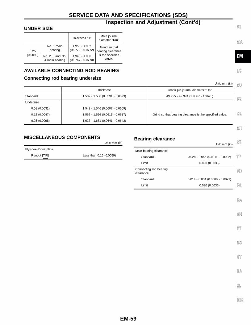
UNDER SIZE
Thickness ‘‘T’’Main journal
diameter ‘‘Dm’’
0.25(0.0098)
No. 1 mainbearing
1.956 - 1.962(0.0770 - 0.0772)
Grind so thatbearing clearance
is the specifiedvalve.
No. 2, 3 and No.4 main bearing
1.948 - 1.956(0.0767 - 0.0770)
AVAILABLE CONNECTING ROD BEARING
Connecting rod bearing undersizeUnit: mm (in)
Thickness Crank pin journal diameter ‘‘Dp’’
Standard 1.502 - 1.506 (0.0591 - 0.0593) 49.955 - 49.974 (1.9667 - 1.9675)
Undersize
0.08 (0.0031) 1.542 - 1.546 (0.0607 - 0.0609)
Grind so that bearing clearance is the specified value.0.12 (0.0047) 1.562 - 1.566 (0.0615 - 0.0617)
0.25 (0.0098) 1.627 - 1.631 (0.0641 - 0.0642)
MISCELLANEOUS COMPONENTSUnit: mm (in)
Flywheel/Drive plate
Runout [TIR] Less than 0.15 (0.0059)
Bearing clearanceUnit: mm (in)
Main bearing clearance
Standard 0.028 - 0.055 (0.0011 - 0.0022)
Limit 0.090 (0.0035)
Connecting rod bearingclearance
Standard 0.014 - 0.054 (0.0006 - 0.0021)
Limit 0.090 (0.0035)
GI
MA
EM
LC
EC
FE
CL
MT
AT
TF
PD
FA
RA
BR
ST
RS
BT
HA
EL
IDX
SERVICE DATA AND SPECIFICATIONS (SDS)Inspection and Adjustment (Cont’d)
EM-59

NOTES
EM-60