Embed Size (px)
Citation preview

Hull Identification Number___________________________________________
Engine Serial Number _______________________________________________
Engine Serial Number _______________________________________________
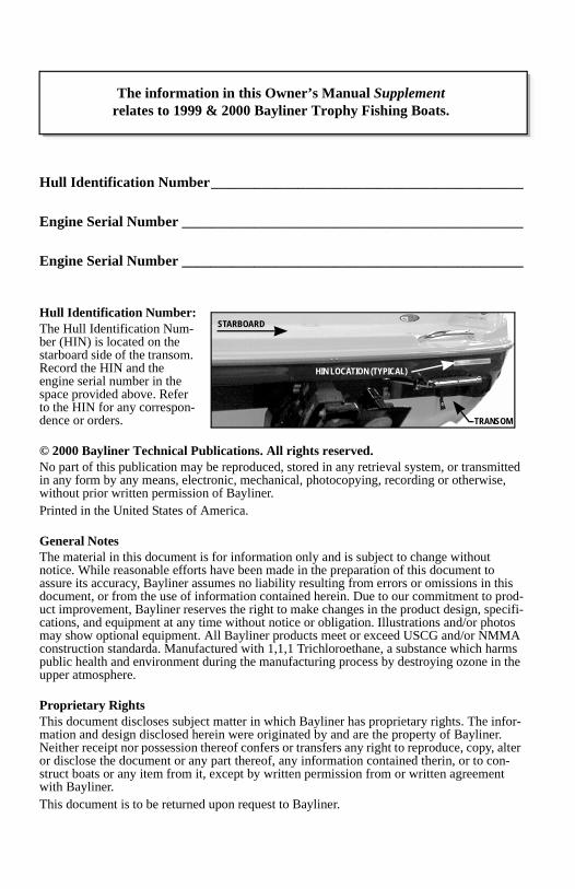
Hull Identification Number:The Hull Identification Num-ber (HIN) is located on the starboard side of the transom. Record the HIN and the engine serial number in the space provided above. Refer to the HIN for any correspon-dence or orders.
© 2000 Bayliner Technical Publications. All rights reserved.No part of this publication may be reproduced, stored in any retrieval system, or transmitted in any form by any means, electronic, mechanical, photocopying, recording or otherwise, without prior written permission of Bayliner.Printed in the United States of America.
General NotesThe material in this document is for information only and is subject to change without notice. While reasonable efforts have been made in the preparation of this document to assure its accuracy, Bayliner assumes no liability resulting from errors or omissions in this document, or from the use of information contained herein. Due to our commitment to prod-uct improvement, Bayliner reserves the right to make changes in the product design, specifi-cations, and equipment at any time without notice or obligation. Illustrations and/or photos may show optional equipment. All Bayliner products meet or exceed USCG and/or NMMA construction standarda. Manufactured with 1,1,1 Trichloroethane, a substance which harms public health and environment during the manufacturing process by destroying ozone in the upper atmosphere.
Proprietary RightsThis document discloses subject matter in which Bayliner has proprietary rights. The infor-mation and design disclosed herein were originated by and are the property of Bayliner. Neither receipt nor possession thereof confers or transfers any right to reproduce, copy, alter or disclose the document or any part thereof, any information contained therin, or to con-struct boats or any item from it, except by written permission from or written agreement with Bayliner.This document is to be returned upon request to Bayliner.
HIN LOCATION (TYPICAL)
TRANSOM
STARBOARD
The information in this Owner’s Manual Supplementrelates to 1999 & 2000 Bayliner Trophy Fishing Boats.

Contents
Chapter 1: Welcome Aboard!
1 Hazard Warning Symbols
2 Dealer Service
2 Boating Experience
2 Engine/Accessories Guidelines
2 Safety Standards
3 Qualified Maintenance
3 Proprietary Rights
3 General Notes
Chapter 2: Product Descriptions
4 Specifications
4 U.S. Coast Guard Maximum Capacities Label
Chapter 3: General Systems
5 Electrical System6 12-Volt DC System7 Shore Power/110-Volt
AC System
9 Navigation and Interior Lights
9 Bilge Blower
10 Fuel System10 Fuel Fills and Vents10 Fuel Filters
11 Bilge Pump
13 Fresh Water System
13 Water Heater
13 Alcohol or Alcohol/Electric Stove (Option)
14 110-Volt AC/12-Volt Refrigerator
14 Portable Toilet
14 Marine Head with Holding Tank
15 Bait Well System
15 Trim Tabs
16 Depth Finder
16 Anchoring
16 Compass
17 Canvas Top Installation:17 Center Console18 Cuddy Cabin Models

Chapter 4: Drawings & Diagrams
19 1703 (FR)
20 1802 (FJ)
21 1903 (FK)
22 2002 (FF)
24 2052 (FD)
25 2352 (FV)
27 2503 (FM)
29 2509 (FW)
33 2802 (FH)
Chapter 5: Wiring Diagrams
38 Shore Power
39 Single Engine (Outboard), Typical
40 Twin Engine (Outboard), Typical
41 Stern Drive, Typical
Limited Warranty
42 What Is Not Covered
42 Other Limitations
42 Your Obligation

Trophy Owner’s Manual Supplement
1
Chapter 1: Welcome Aboard!
This Owner’s Manual Supplement was prepared to provide specific infor-mation about your boat. Read the Owner’s Manual and this supplement carefully, paying particular attention to the Limited Warranty section.
Keep this supplement in a secure place and hand it over to the new owner when you sell the boat.
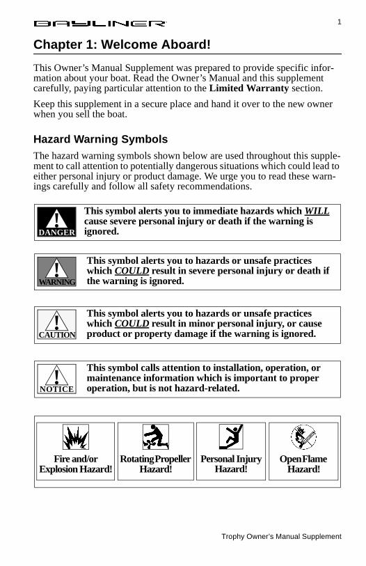
Hazard Warning SymbolsThe hazard warning symbols shown below are used throughout this supple-ment to call attention to potentially dangerous situations which could lead to either personal injury or product damage. We urge you to read these warn-ings carefully and follow all safety recommendations.
DANGER!
This symbol alerts you to immediate hazards which WILL cause severe personal injury or death if the warning is ignored.
This symbol alerts you to hazards or unsafe practices which COULD result in severe personal injury or death if the warning is ignored.WARNING
!
This symbol alerts you to hazards or unsafe practices which COULD result in minor personal injury, or cause product or property damage if the warning is ignored.CAUTION
!
This symbol calls attention to installation, operation, or maintenance information which is important to proper operation, but is not hazard-related.NOTICE
!
Fire and/or Explosion Hazard!
Rotating Propeller Hazard!
Personal Injury Hazard!
Open Flame Hazard!
Trophy Owner’s Manual Supplement
2 Chapter 1: Welcome Aboard!
Dealer ServiceMake certain that you receive a full explanation of all systems from the sell-ing dealer before taking delivery of your boat. Your selling dealer is your key to service. If you experience any problems with your new boat, immedi-ately contact the selling dealer. If for any reason your selling dealer is unable to help, you can call us direct on our customer service hotline:
360-435-8957 or send us a FAX: 360-403-4235
Boating ExperienceIf this is your first boat or if you are changing to a type of boat you are not familiar with, for your own comfort and safety, please ensure that you obtain handling and operating experience before assuming command of the boat. Your selling dealer, national sailing federation or yacht club will be pleased to advise you of local sea schools, or competent instructors.
Engine/Accessories GuidelinesYour boat’s engine (or engines) and accessories were selected to provide optimum performance and utility. Installation of different engines or other accessories may cause undesirable handling characteristics. Should you choose to install different engines, or to add accessories that will affect the boat’s running trim, have an experienced marine technician perform a safety inspection and a handling test before operating your boat by yourself again.
Safety StandardsYour boat’s mechanical and electrical systems were designed to meet safety standards in effect at the time it was constructed. Some of these standards were mandated by law. All of them were designed to insure your safety, and the safety of other people, vessels and property.
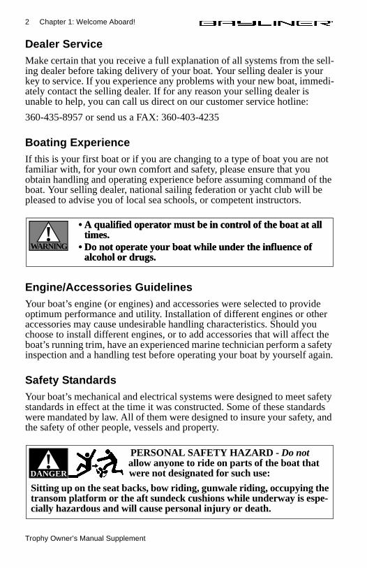
• A qualified operator must be in control of the boat at all times.
• Do not operate your boat while under the influence of alcohol or drugs.
WARNING!
• A qualified operator must be in control of the boat at all times.
• Do not operate your boat while under the influence of alcohol or drugs.
DANGER!
PERSONAL SAFETY HAZARD - Do not allow anyone to ride on parts of the boat that were not designated for such use:
Sitting up on the seat backs, bow riding, gunwale riding, occupying the transom platform or the aft sundeck cushions while underway is espe-cially hazardous and will cause personal injury or death.
Trophy Owner’s Manual Supplement
Chapter 1: Welcome Aboard! 3
Please read the Owner’s Manual, warning labels and all literature supplied with your boat for important safety standards and hazard information.
Qualified Maintenance
Failure to maintain these systems as designed could violate the laws in your jurisdiction, and could expose you and other people to the danger of bodily injury or accidental death. We recommend that you follow the instructions provided in this supplement, the Owner’s Manual, the engine owner’s man-ual, and the accessory instruction sheets included with your boat.
Proprietary RightsThis document discloses subject matter in which Bayliner has proprietary rights. The information and design disclosed herein were originated by and are the property of Bayliner. Neither receipt nor possession thereof confers or transfers any right to reproduce, copy, alter or disclose the document or any part thereof, any information contained therein, or to construct boats or any item from it, except by written permission from or written agreement with Bayliner. This document is to be returned upon request to Bayliner.
General NotesThe information contained herein is subject to change without notice and is not to be used in conjunction with sales or advertising, except as may be expressly permitted in writing by Bayliner. Actual operating results will vary depending on conditions and variables.
All Bayliner products meet or exceed USCG and/or NMMA construction standards.
Due to our commitment to product improvement, we reserve the right to change, without notice or other obligation, the specifications or other infor-mation contained in this publication.Manufactured with 1,1,1-Trichloroethane, a substance which harms public health and environment (during the man-ufacturing process) by destroying ozone in the upper atmosphere.
To maintain the integrity and safety of your boat, only qualified people should perform maintenance on, or in any way modify; the steering system, propulsion system, engine control system, fuel system, environmental control system, or electrical system.
WARNING!
Trophy Owner’s Manual Supplement
4
Chapter 2: Product Descriptions
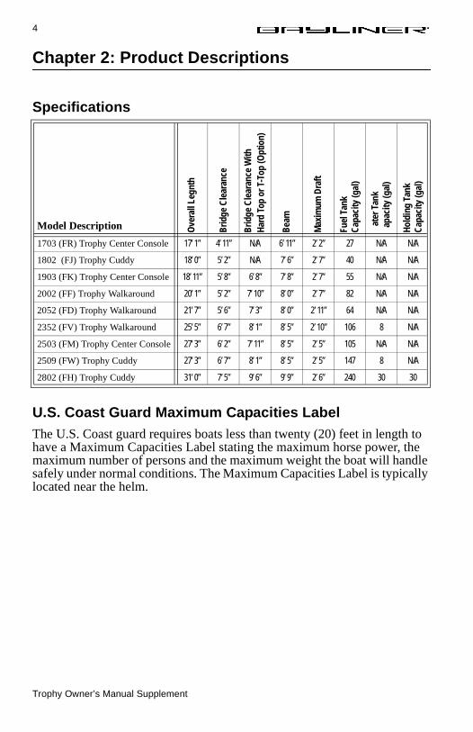
Specifications
U.S. Coast Guard Maximum Capacities LabelThe U.S. Coast guard requires boats less than twenty (20) feet in length to have a Maximum Capacities Label stating the maximum horse power, the maximum number of persons and the maximum weight the boat will handle safely under normal conditions. The Maximum Capacities Label is typically located near the helm.
Model Description
1703 (FR) Trophy Center Console 17’ 1” 4’ 11” N/A 6’ 11” 2’ 2” 27 N/A N/A
1802 (FJ) Trophy Cuddy 18’ 0” 5’ 2” N/A 7’ 6” 2’ 7” 40 N/A N/A
1903 (FK) Trophy Center Console 18’ 11” 5’ 8” 6’ 8” 7’ 8” 2’ 7” 55 N/A N/A
2002 (FF) Trophy Walkaround 20’ 1” 5’ 2” 7’ 10” 8’ 0” 2’ 7” 82 N/A N/A
2052 (FD) Trophy Walkaround 21’ 7” 5’ 6” 7’ 3” 8’ 0” 2’ 11” 64 N/A N/A
2352 (FV) Trophy Walkaround 25’ 5” 6’ 7” 8’ 1” 8’ 5” 2’ 10” 106 8 N/A
2503 (FM) Trophy Center Console 27’ 3” 6’ 2” 7’ 11” 8’ 5” 2’ 5” 105 N/A N/A
2509 (FW) Trophy Cuddy 27’ 3” 6’ 7” 8’ 1” 8’ 5” 2’ 5” 147 8 N/A
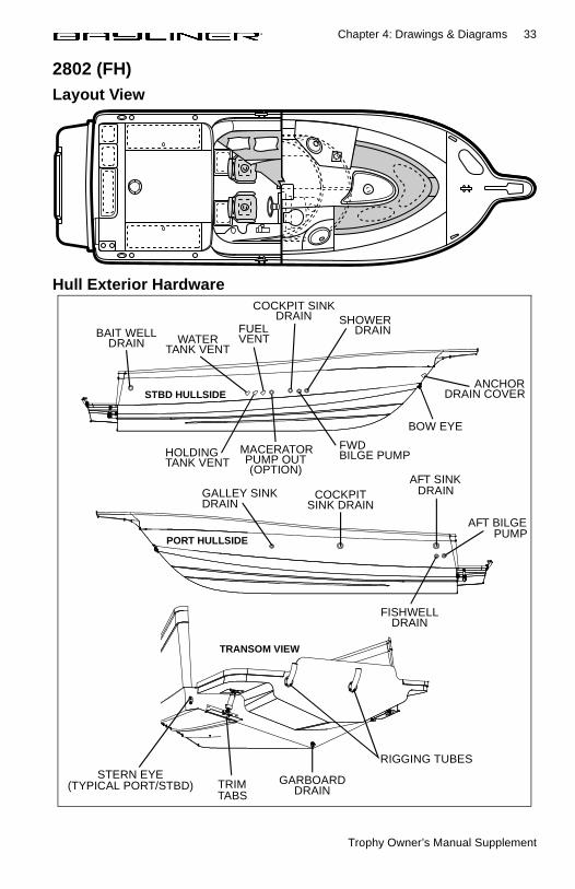
2802 (FH) Trophy Cuddy 31’ 0” 7’ 5” 9’ 6” 9’ 9” 2’ 6” 240 30 30
Ove
rall
Legn
th
Brid
ge C
lear
ance
Brid
ge C
lear
ance
With
Hard
Top
or T
-Top
(Opt
ion)
Beam
Max
imum
Dra
ft
Fuel
Tan
kCa
paci
ty (g
al)
ater
Tan
kap
acity
(gal
)
Hold
ing
Tank
Capa
city
(gal
)

Trophy Owner’s Manual Supplement
5
Chapter 3: General Systems
Electrical SystemRead and understand the Electrical Section of the Owner’s Manual.
DANGER! EXTREME FIRE/EXPLOSION
and ELECTRIC SHOCK HAZARD!
• To minimize the risks of fire and explosion, NEVER install knife switches or other arcing devices in the fuel compartments.
• NEVER substitute automotive parts for marine parts. Electrical, ignition and fuel system parts were designed and made to comply with rules and regulations that minimize risks of fire and explosion.
• DO NOT modify the electrical systems or relevant drawings.• Fuel fumes are heavier than air and will collect in the bilge areas
where they can be accidently ignited. Visually and by smell (sniff test), check the engine and fuel compartments for fumes or accu-mulation of fuel. Operate the bilge blower for at least four minutes prior to engine starting, electrical system maintenance or activa-tion of electrical devices.
• Only qualified personnel should install batteries and/or perform electrical system maintenance.
• Insure that all battery switches are in the OFF position before per-forming any work in the engine spaces.
• Minimize the danger of fire and explosion by not exposing batter-ies to open flame or sparks. It is also important that no one smoke anywhere near the batteries.
SHOCK and/or ELECTRICALSYSTEM HAZARD!
• NEVER disconnect the battery cables while the engine is running, as this can cause damage to your boat’s electrical system components.
• The battery charging systems (alternator and, if applicable, bat-tery charger) installed are designed to charge conventional lead-acid batteries. Before installing gel-cell or other new technology batteries, consult with the battery manufacturer about charging system requirements.
CAUTION!
Trophy Owner’s Manual Supplement
6 Chapter 3: General Systems
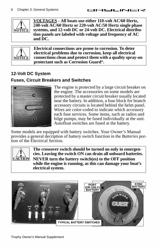
12-Volt DC SystemFuses, Circuit Breakers and Switches
The engine is protected by a large circuit breaker on the engine. The accessories on some models are protected by a master circuit breaker usually located near the battery. In addition, a fuse block for branch accessory circuits is located behind the helm panel. Wires are color-coded to indicate which accessory each fuse services. Some items, such as radios and bilge pumps, may be fused individually at the unit. Autofloat switches are fused at the battery.
Some models are equipped with battery switches. Your Owner’s Manual provides a general decription of battery switch function in the Batteries por-tion of the Electrical Section.
VOLTAGES - All boats use either 110-volt AC/60 Hertz, 240-volt AC/60 Hertz or 220-volt AC/50 Hertz single phase systems, and 12-volt DC or 24-volt DC. Electrical distribu-tion panels are labeled with voltage and frequency of AC and DC.
NOTICE!
Electrical connections are prone to corrosion. To deter electrical problems due to corrosion, keep all electrical connections clean and protect them with a quality spray-on protectant such as Corrosion Guard®.
NOTICE!
TYPICAL ACCESSORYCIRCUIT MASTER BREAKER
The crossover switch should be turned on only in emergen-cies. Leaving the switch ON can drain all onboard batteries.NEVER turn the battery switch(es) to the OFF position while the engine is running, as this can damage your boat’s electrical system.
CAUTION!
PORT(OR ONLY)BATTERY
STBDBATTERY
TYPICAL BATTERY SWITCHES

Trophy Owner’s Manual Supplement
Chapter 3: General Systems 7
Shore Power/110-Volt AC SystemYour boat may be equipped with a 110 volt AC system. AC systems are energized by dockside shore power. Standard dockside receptacles and cords provided are rated at 30 amps. Since some shore installations do not have 30 amp service, we recommend the purchase of 15 amp and 20 amp adapters. Note: When 15 amp or 20 amp adapters are used there will be a corresponding drop in supplied AC power.
FIRE/EXPLOSION/SHOCK HAZARD!
• To minimize shock and fire hazard, DO NOT modify electrical systems or relevant drawings. ONLY qualified personnel should install batter-ies and/or perform electrical system maintenance. DO NOT alter shore power connectors and only use compatible connectors.
DANGER!
SHOCK/ELECTRICAL SYSTEM DAMAGE HAZARD!
• Never connect dockside power to your boat outside North America unless you have purchased the International electrical conversion option, which is rated for 220-volt/50 Hertz. North American systems are rated for 110-volt/60 Hertz power.
• Use double insulated or three-wire protected electrical appliances when possible.
CAUTION!
WATER HEATER DAMAGE HAZARD! DO NOT energize the AC water heater electrical circuit until the heater is com-pletely filled with water. Even momentary operation in a dry tank will damage the heating elements. Warranty replace-ments will not be made on elements or tank damaged in this manner. The tank is full if water flows from the tap when the hot water is turned on in the galley.
CAUTION!
When using shore power, the simultaneous operation of sev-eral AC accessories can result in an overloaded circuit. It may be necessary to turn off one accessory while operating another.
NOTICE!
Trophy Owner’s Manual Supplement
8 Chapter 3: General Systems
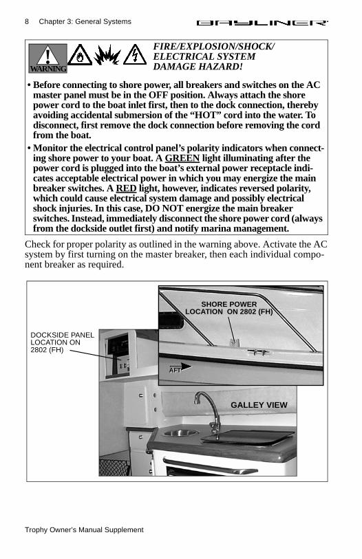
Check for proper polarity as outlined in the warning above. Activate the AC system by first turning on the master breaker, then each individual compo-nent breaker as required.
FIRE/EXPLOSION/SHOCK/ELECTRICAL SYSTEM DAMAGE HAZARD!
• Before connecting to shore power, all breakers and switches on the AC master panel must be in the OFF position. Always attach the shore power cord to the boat inlet first, then to the dock connection, thereby avoiding accidental submersion of the “HOT” cord into the water. To disconnect, first remove the dock connection before removing the cord from the boat.
• Monitor the electrical control panel’s polarity indicators when connect-ing shore power to your boat. A GREEN light illuminating after the power cord is plugged into the boat’s external power receptacle indi-cates acceptable electrical power in which you may energize the main breaker switches. A RED light, however, indicates reversed polarity, which could cause electrical system damage and possibly electrical shock injuries. In this case, DO NOT energize the main breaker switches. Instead, immediately disconnect the shore power cord (always from the dockside outlet first) and notify marina management.
WARNING!
DOCKSIDE PANELLOCATION ON 2802 (FH)
SHORE POWERLOCATION ON 2802 (FH)
AFTAFT
GALLEY VIEW
Trophy Owner’s Manual Supplement
Chapter 3: General Systems 9
Navigation and Interior LightsWe strongly recommend that you understand navigation light usage as out-lined in the Navigation section of the Owner’s Manual. The navigation and interior lights supplied with your boat are of top quality, but may periodi-cally fail for a variety of reasons:
1. There may be a blown fuse (Replace the fuse in the switch panel).2. The bulb may be burned out (Carry spare bulbs for replacement).3. The bulb base may be corroded (Clean the base periodically and coat it
with non-conductive grease).4. A wire may have come loose or may be damaged (Repair as required).
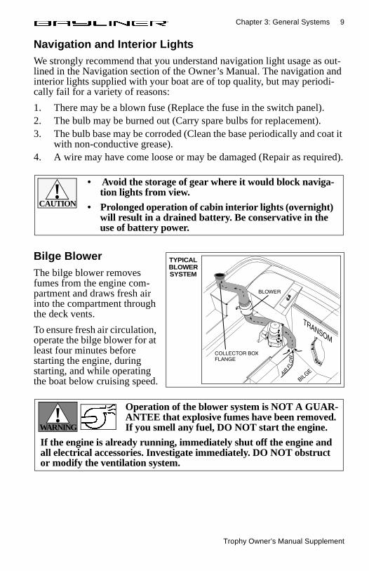
Bilge BlowerThe bilge blower removes fumes from the engine com-partment and draws fresh air into the compartment through the deck vents.
To ensure fresh air circulation, operate the bilge blower for at least four minutes before starting the engine, during starting, and while operating the boat below cruising speed.
• Avoid the storage of gear where it would block naviga-tion lights from view.
• Prolonged operation of cabin interior lights (overnight) will result in a drained battery. Be conservative in the use of battery power.
CAUTION!
TYPICALBLOWERSYSTEM
Operation of the blower system is NOT A GUAR-ANTEE that explosive fumes have been removed. If you smell any fuel, DO NOT start the engine.
If the engine is already running, immediately shut off the engine and all electrical accessories. Investigate immediately. DO NOT obstruct or modify the ventilation system.
WARNING!
Trophy Owner’s Manual Supplement
10 Chapter 3: General Systems
Fuel System
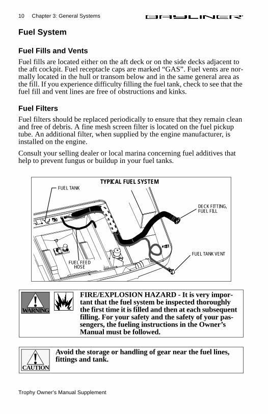
Fuel Fills and VentsFuel fills are located either on the aft deck or on the side decks adjacent to the aft cockpit. Fuel receptacle caps are marked “GAS”. Fuel vents are nor-mally located in the hull or transom below and in the same general area as the fill. If you experience difficulty filling the fuel tank, check to see that the fuel fill and vent lines are free of obstructions and kinks.
Fuel FiltersFuel filters should be replaced periodically to ensure that they remain clean and free of debris. A fine mesh screen filter is located on the fuel pickup tube. An additional filter, when supplied by the engine manufacturer, is installed on the engine.
Consult your selling dealer or local marina concerning fuel additives that help to prevent fungus or buildup in your fuel tanks.
FUEL TANK
FUEL TANK VENT
DECK FITTING,FUEL FILL
TYPICAL FUEL SYSTEM
FUEL FEEDHOSE
FIRE/EXPLOSION HAZARD - It is very impor-tant that the fuel system be inspected thoroughly the first time it is filled and then at each subsequent filling. For your safety and the safety of your pas-sengers, the fueling instructions in the Owner’s Manual must be followed.
WARNING!
Avoid the storage or handling of gear near the fuel lines, fittings and tank.
CAUTION!
Trophy Owner’s Manual Supplement
Chapter 3: General Systems 11
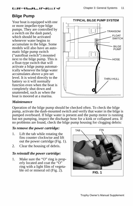
Bilge PumpYour boat is equipped with one or more impeller-type bilge pumps. They are controlled by a switch on the dash panel, which should be activated whenever water begins to accumulate in the bilge. Some models will also have an auto-matic bilge pump switch (“autofloat switch”) mounted next to the bilge pump. This is a float-type switch that will activate a bilge pump automat-ically whenever the bilge water accumulates above a pre-set level. It is wired directly to the battery so it will normally function even when the boat is completely shut down and unattended, such as when the boat is moored at a marina.
Maintenance
Operation of the bilge pump should be checked often. To check the bilge pump, activate the dash-mounted switch and verify that water in the bilge is pumped overboard. If bilge water is present and the pump motor is running but not pumping, inspect the discharge hose for a kink or collapsed area. If no problems are found, check the bilge pump housing for clogging debris:
To remove the power cartridge:
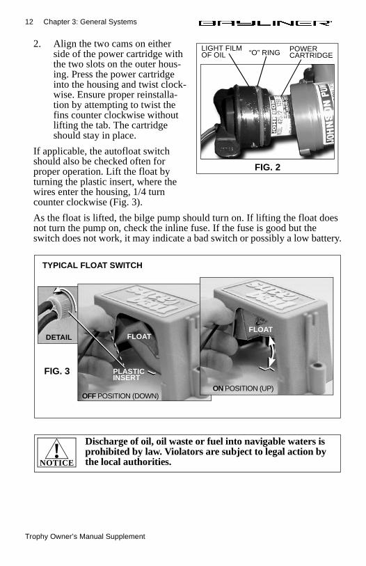
1. Lift the tab while rotating the fins counter clockwise and lift out the power cartridge (Fig. 1).
2. Clear the housing of debris.
To reinstall the power cartridge:
1. Make sure the “O” ring is prop-erly located and coat the “O” ring with a light film of vegeta-ble oil or mineral oil (Fig. 2).
TRANSOM
FLOAT
BILGE
HOSE
THRU-HULL
SWITCH
TYPICAL BILGE PUMP SYSTEM
PUMP
FIG. 1
TAB FIN
Trophy Owner’s Manual Supplement
12 Chapter 3: General Systems
2. Align the two cams on either side of the power cartridge with the two slots on the outer hous-ing. Press the power cartridge into the housing and twist clock-wise. Ensure proper reinstalla-tion by attempting to twist the fins counter clockwise without lifting the tab. The cartridge should stay in place.
If applicable, the autofloat switch should also be checked often for proper operation. Lift the float by turning the plastic insert, where the wires enter the housing, 1/4 turn counter clockwise (Fig. 3).
As the float is lifted, the bilge pump should turn on. If lifting the float does not turn the pump on, check the inline fuse. If the fuse is good but the switch does not work, it may indicate a bad switch or possibly a low battery.
FIG. 2
OF OILLIGHT FILM
“O” RING POWERCARTRIDGE
FLOAT
PLASTICINSERT
DETAIL
OFF POSITION (DOWN)
FLOAT
ON POSITION (UP)
TYPICAL FLOAT SWITCH
FIG. 3
Discharge of oil, oil waste or fuel into navigable waters is prohibited by law. Violators are subject to legal action by the local authorities.NOTICE
!
Trophy Owner’s Manual Supplement
Chapter 3: General Systems 13
Fresh Water SystemYour boat features a pressure-type (demand) fresh water system. This sys-tem operates when the pump switch, located near in the galley, is turned ON. Turn the pump switch OFF when the boat is not in use and when the water tank is empty.
Stored water can become stagnant and distasteful. Pump the water tank dry before leaving your boat unattended for long periods of time. Occasionally you may want to disinfect your water system. Ask your selling dealer about available treatments and procedures.
Your boat may be equipped with a shower. Please read and follow the man-ufacturer’s operating instructions supplied in your baot’s owner’s packet.
Water HeaterYour boat may feature a water heater. Please refer to the owner’s packet for manufacturer’s operating instructions. The water heater is connected to the AC power system. If your boat is equipped with optional freshwater engine cooling, the coolant from the closed engine cooling system may be circu-lated through the hot water tank for heating of potable water.
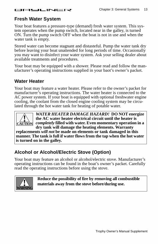
Alcohol or Alcohol/Electric Stove (Option)Your boat may feature an alcohol or alcohol/electric stove. Manufacturer’s operating instructions can be found in the boat’s owner’s packet. Carefully read the operating instructions before using the stove.
WATER HEATER DAMAGE HAZARD! DO NOT energize the AC water heater electrical circuit until the heater is completely filled with water. Even momentary operation in a dry tank will damage the heating elements. Warranty
replacements will not be made on elements or tank damaged in this manner. The tank is full if water flows from the tap when the hot water is turned on in the galley.
CAUTION!
Reduce the possibility of fire by removing all combustible materials away from the stove before/during use.
WARNING!
Trophy Owner’s Manual Supplement
14 Chapter 3: General Systems
110-Volt AC/12-Volt RefrigeratorYour boat may feature a 110-volt AC/12-volt DC refrigerator. Please refer to the manufacturer’s instructions supplied in your boat’s owner’s packet. The refrigerator operates on 12-volt DC power unless the 110-volt AC sys-tem is hooked up to shore power and the AC refrigerator breaker is ON.
Portable ToiletIf your boat features a portable toilet, carefully read and follow the manu-facturer’s operating instructions supplied in your owner’s packet.
Marine Head with Holding TankYour boat may come equipped with with a marine head and holding tank. Be sure to follow the manufacturer’s operating instructions included in the boat’s owner’s packet.
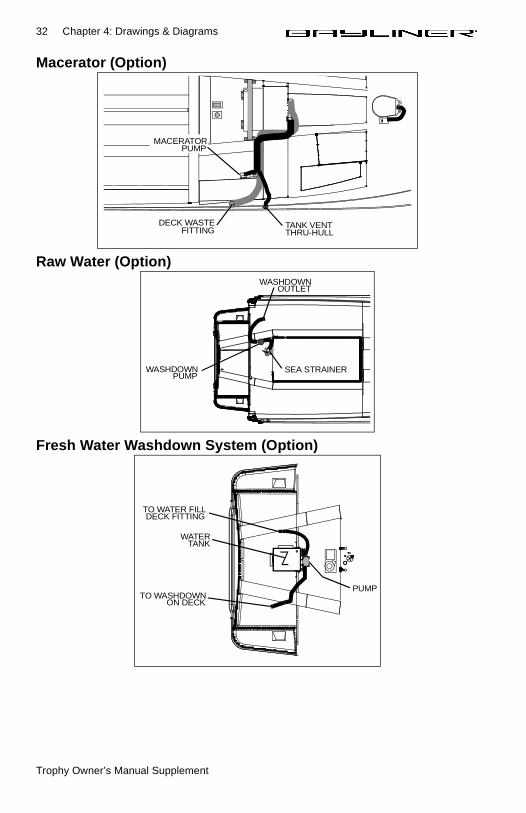
Seawater is used to flush waste from the toilet into the holding tank. The holding tank is plumbed to a waste fitting on the deck for use at a dockside pump-out station, and to a macerator pump so that waste may be pumped overboard (where regulations permit). The switch for the macerator is usu-ally located at the helm station.
If at any time you are unable to pump water into the bowl, the probable cause is debris in the pump diaphragm. To remedy this, shut the inlet sea-cock and dismantle the pump. The pump is generally held together with six screws. The design is simple and the problem will be obvious when the pump body is split open.
To winterize the toilet, shut off the intake valve and pump until the bowl is dry. Remove the drain plug in the base and pump again to remove all water. Do not fill the bowl with antifreeze. The inlet seacock should be left closed while the boat is underway, or whenever the boat is left moored in the water.
In less than 24 hours, the refrigerator can render a 100-amp battery useless for engine starting. When operating on 12-volts, it is advised that the cold setting not be set higher than two (2). It is also advisable to turn off your refrigerator at night or when not in use. If you are going out for more than a day and
cannot connect to dockside power, plan to run the engine each day to maintain a charged battery.
NOTICE!
Trophy Owner’s Manual Supplement
Chapter 3: General Systems 15
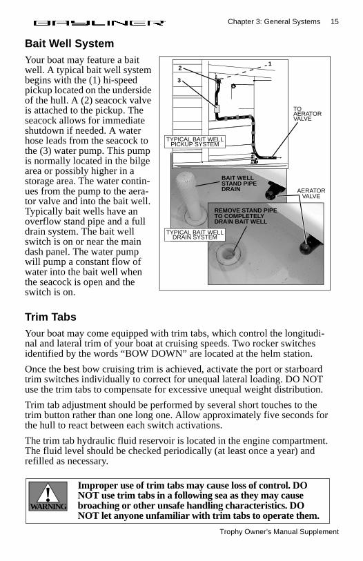
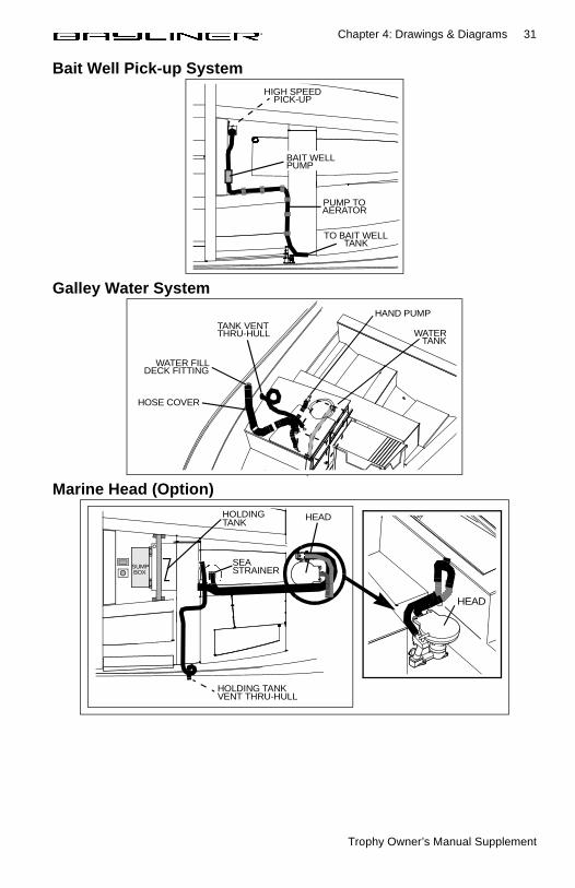
Bait Well SystemYour boat may feature a bait well. A typical bait well system begins with the (1) hi-speed pickup located on the underside of the hull. A (2) seacock valve is attached to the pickup. The seacock allows for immediate shutdown if needed. A water hose leads from the seacock to the (3) water pump. This pump is normally located in the bilge area or possibly higher in a storage area. The water contin-ues from the pump to the aera-tor valve and into the bait well. Typically bait wells have an overflow stand pipe and a full drain system. The bait well switch is on or near the main dash panel. The water pump will pump a constant flow of water into the bait well when the seacock is open and the switch is on.
Trim TabsYour boat may come equipped with trim tabs, which control the longitudi-nal and lateral trim of your boat at cruising speeds. Two rocker switches identified by the words “BOW DOWN” are located at the helm station.
Once the best bow cruising trim is achieved, activate the port or starboard trim switches individually to correct for unequal lateral loading. DO NOT use the trim tabs to compensate for excessive unequal weight distribution.
Trim tab adjustment should be performed by several short touches to the trim button rather than one long one. Allow approximately five seconds for the hull to react between each switch activations.
The trim tab hydraulic fluid reservoir is located in the engine compartment. The fluid level should be checked periodically (at least once a year) and refilled as necessary.
BAIT WELLSTAND PIPEDRAIN AERATOR
VALVE
REMOVE STAND PIPETO COMPLETELYDRAIN BAIT WELL
TOAERATORVALVE
TYPICAL BAIT WELLPICKUP SYSTEM
TYPICAL BAIT WELLDRAIN SYSTEM
12
3
Improper use of trim tabs may cause loss of control. DO NOT use trim tabs in a following sea as they may cause broaching or other unsafe handling characteristics. DO NOT let anyone unfamiliar with trim tabs to operate them.
WARNING!
Trophy Owner’s Manual Supplement
16 Chapter 3: General Systems
Depth FinderYour boat may come equipped with a depth finder. The depth finder comes with its own owner’s manual. We suggest that you read it carefully before using the unit.
Trophy models not equipped with depth finders may have a tube laminated into the hull for installing a depth finder transducer. The tube goes though bulkheads which serve as fuel vapor barriers, so both ends of the tube have been sealed. To install a transducer, pull the sealed ends off the tube and use the string inside to pull the tranducer cable through. After pulling the cable through, you MUST reseal both ends of the tube to ensure it is vapor-tight.
AnchoringWe strongly recommend that you read and understand the Anchoring sec-tion of the Owner’s Manual.
CompassYour boat may come equipped with a compass. Carefully read and follow the manufacturer’s calibration and operating instructions provided in the owner’s packet.
DO NOT use the depth finder as a navigational aid to prevent collision, grounding, boat damage or personal injury. When the boat is moving, submerged objects will not be seen until they are already under the boat. Bottom depths may change too
quickly to allow time for the boat operator to react. If you suspect shallow water or submerged objects, operate the boat at very slow speeds.
WARNING!
Failure to reseal the transducer routing tube after remov-ing the factory installed seals can cause fire, explosion and possible injury or death.WARNING
!
FLOODING AND SWAMPING HAZARD - Never anchor by the stern alone--there is less freeboard and flooding or swamping is more likely to occur. When using only one anchor, secure the anchor line to the bow cleat or bow eye.
WARNING!
Trophy Owner’s Manual Supplement
Chapter 3: General Systems 17
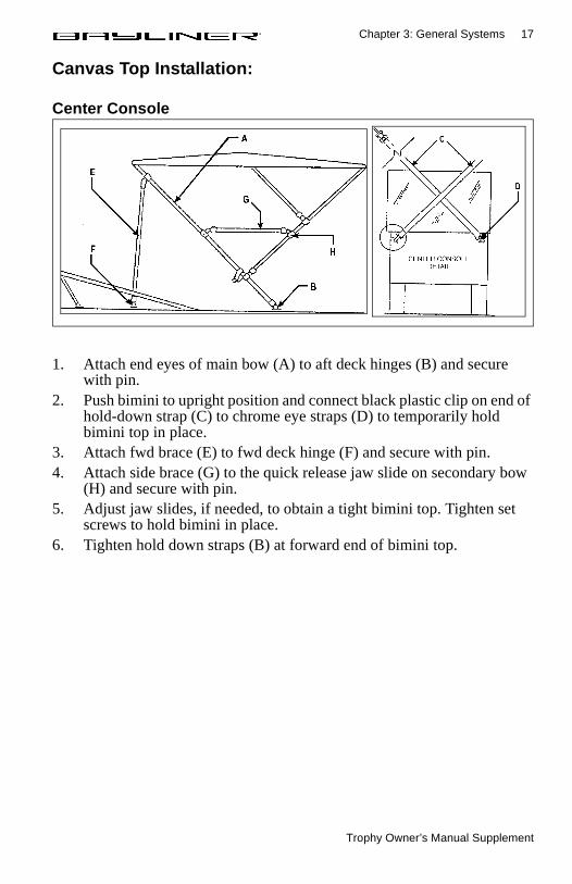
Canvas Top Installation:
Center Console
1. Attach end eyes of main bow (A) to aft deck hinges (B) and secure with pin.
2. Push bimini to upright position and connect black plastic clip on end of hold-down strap (C) to chrome eye straps (D) to temporarily hold bimini top in place.
3. Attach fwd brace (E) to fwd deck hinge (F) and secure with pin.4. Attach side brace (G) to the quick release jaw slide on secondary bow
(H) and secure with pin.5. Adjust jaw slides, if needed, to obtain a tight bimini top. Tighten set
screws to hold bimini in place.6. Tighten hold down straps (B) at forward end of bimini top.
Trophy Owner’s Manual Supplement
18 Chapter 3: General Systems
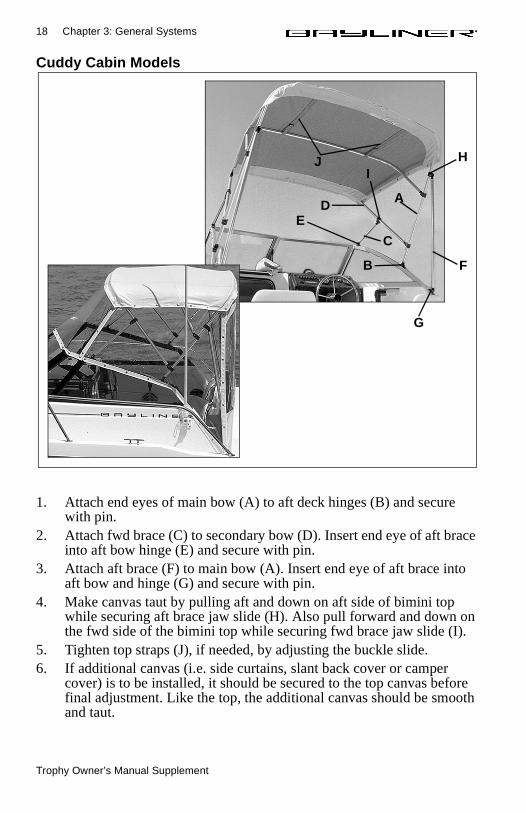
Cuddy Cabin Models
1. Attach end eyes of main bow (A) to aft deck hinges (B) and secure with pin.
2. Attach fwd brace (C) to secondary bow (D). Insert end eye of aft brace into aft bow hinge (E) and secure with pin.
3. Attach aft brace (F) to main bow (A). Insert end eye of aft brace into aft bow and hinge (G) and secure with pin.
4. Make canvas taut by pulling aft and down on aft side of bimini top while securing aft brace jaw slide (H). Also pull forward and down on the fwd side of the bimini top while securing fwd brace jaw slide (I).
5. Tighten top straps (J), if needed, by adjusting the buckle slide.6. If additional canvas (i.e. side curtains, slant back cover or camper
cover) is to be installed, it should be secured to the top canvas before final adjustment. Like the top, the additional canvas should be smooth and taut.
J H
A
I
D
C
E
B F
G
Trophy Owner’s Manual Supplement
19
Chapter 4: Drawings & Diagrams
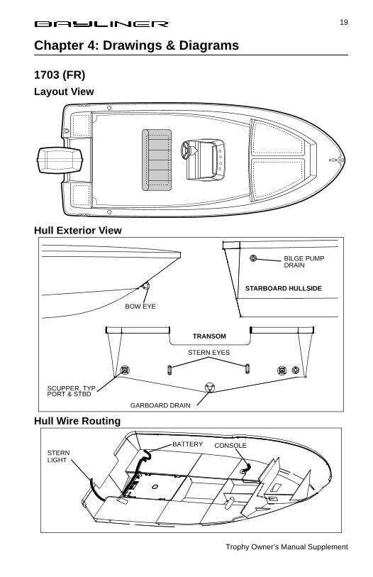
1703 (FR)Layout View
Hull Exterior View
Hull Wire Routing
BILGE PUMPDRAIN
BOW EYE
SCUPPER, TYP.
GARBOARD DRAIN
STERN EYES
STARBOARD HULLSIDE
TRANSOM
PORT & STBD
STERNBATTERY CONSOLE
LIGHT

Trophy Owner’s Manual Supplement
20 Chapter 4: Drawings & Diagrams
1802 (FJ)Layout View
Hull Exterior Hardware
Electrical Harness
GARBARD DRAIN
DRAIN
BOW EYE
BLGE PUMPDRAIN
(TYPICAL PORT/STBD)STERN EYE
TRANSOM
STBD HULLSIDE
FISH LOCKER
SUMP
STERN
DOMELIGHT
WIPER(OPTION)
BOWLIGHT
LIGHT
Trophy Owner’s Manual Supplement
Chapter 4: Drawings & Diagrams 21
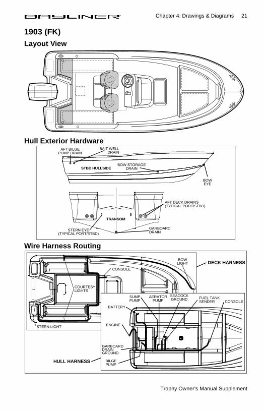
1903 (FK)Layout View
Hull Exterior Hardware
Wire Harness Routing
AFT DECK DRAINS(TYPICAL PORT/STBD)
GARBOARDDRAINSTERN EYE
(TYPICAL PORT/STBD)
AFT BILGEPUMP DRAIN
BAIT WELLDRAIN
BOW STORAGEDRAIN
BOWEYE
TRANSOM
STBD HULLSIDE
CONSOLE
BOWLIGHT
STERN LIGHT
COURTESYLIGHTS
FUEL TANKSENDER
BATTERY
SUMPPUMP
SEACOCKGROUND
ENGINE
GARBOARDDRAIN
BILGEPUMP
AERATORPUMP CONSOLE
GROUND
DECK HARNESS
HULL HARNESS
Trophy Owner’s Manual Supplement
22 Chapter 4: Drawings & Diagrams
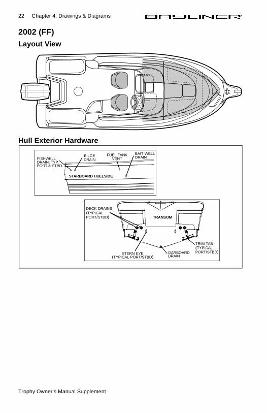
2002 (FF)Layout View
Hull Exterior Hardware
step
BILGEFISHWELL
FUEL TANK BAIT WELLDRAIN
DRAIN, TYP.DRAIN VENT
STARBOARD HULLSIDE
PORT & STBD.
STERN EYE(TYPICAL PORT/STBD)
TRIM TAB(TYPICAL
GARBOARDDRAIN
TRANSOM
DECK DRAINS(TYPICALPORT/STBD)
PORT/STBD)
Trophy Owner’s Manual Supplement
Chapter 4: Drawings & Diagrams 23
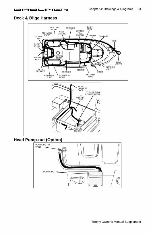
Deck & Bilge Harness
Head Pump-out (Option)
TO BILGE PUMP& FLOAT SWITCH
BILGEHARNESSPLUG
TOBAIT WELL
PUMP
TO FUELSENDER
BOWLIGHTS
HORN
INTERIORLIGHTSTEREO
WIPERSPEAKER
COURTESYLIGHT
FISH WELLPUMP
BILGEPLUG
ENGINEPLUG
ANTENNAWIRE
ACCYBREAKER
STERNLIGHT
SPEAKER
FUELGROUND
COURTESYLIGHT
FISH WELLPUMP
STERNLIGHT
SHIFTERKILL
SWITCH
DASHPLUG
WIPER COMPASS
PORTA-POTTY
PORTA-POTTYVENT
Trophy Owner’s Manual Supplement
24 Chapter 4: Drawings & Diagrams
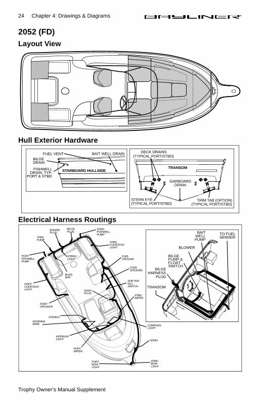
2052 (FD)Layout View
Hull Exterior Hardware
Electrical Harness Routings
steprod holder
BILGE
FISHWELL
FUEL VENT BAIT WELL DRAIN
DRAIN, TYP. STARBOARD HULLSIDE
PORT & STBD
DRAIN
STERN EYE(TYPICAL PORT/STBD)
TRIM TAB (OPTION)(TYPICAL PORT/STBD)
GARBOARDDRAIN
TRANSOM
(TYPICAL PORT/STBD)DECK DRAINS
PORTBOWLIGHT
STBD.BOWLIGHT
HORN
PORTWIPER
STEREO
PORTSPEAKER
PORTCOURTESYLIGHT
PORTFISHWELLPUMP
TRIMPUMP
BUSSBAR
STERNLIGHT
ENGINEPLUG
BILGEPLUG
STBD.FISHWELL
STBD.COURTESYLIGHT
FUELGROUND
STBD.SPEAKER
SHIFTERKILLSWITCH
DASHPLUG
STBD.WIPER
COMPASSLIGHT
INTERIORLIGHT
PUMP
ANTENNAWIRE
TO FUELSENDER
BILGEPUMP &
BILGEHARNESS
PLUG
BLOWER
BAITWELLPUMP
FLOATSWITCH
TRANSOM
Trophy Owner’s Manual Supplement
Chapter 4: Drawings & Diagrams 25
2352 (FV)Layout View
Hull Exterior Hardware
Deck Harness Routing
GARBOARD DRAIN
FUEL
FUEL TANK VENT
DECK DRAINS(TYP. PORT/STBD)
TRIM TABS(TYP. PORT/STBD)
STERN EYE(TYP. PORT/STBD)
AFT BILGE
BOW EYE
GALLEY WATER
GALLEY
DRAIN
SINK DRAIN
TANK VENTMARINE HEAD
(OPTIONAL)
FWDBILGE PUMP
HOLDINGTANK VENT(OPTIONAL)
MACERATOR(OPTION)
BLOWER VENTS(TYP. PORT/STBD)
AFT SUMP PUMPOUT (PORT SIDE)
FILL
STBD HULLSIDE
TRANSOM
DASH PANEL
COURTESY
BOW LIGHT
STERN
SHIFTER
SPEAKER
ENGINE
TRIM PUMPSPEAKER
FWD HULL
STEP LIGHT
CABIN LIGHTS
COURTESY
WIPER
COMPASS
HORN
CABIN LIGHT
LIGHT
HARNESS
LIGHT
LIGHT
BILGE HARNESS
FUEL TANK
Trophy Owner’s Manual Supplement
26 Chapter 4: Drawings & Diagrams
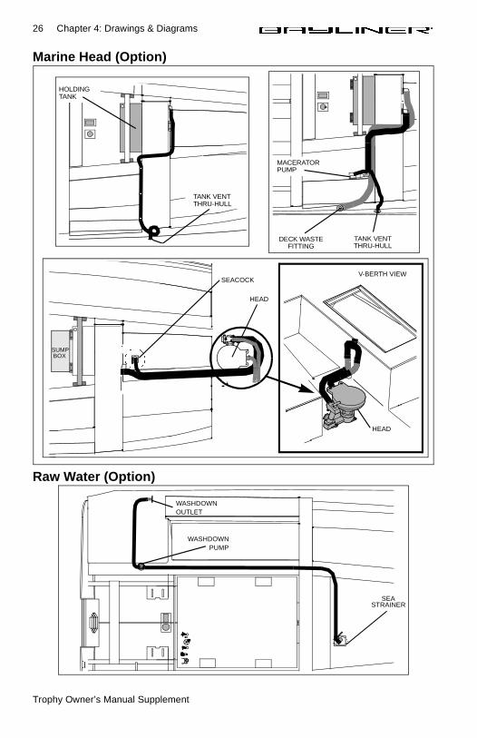
Marine Head (Option)
Raw Water (Option)
HOLDINGTANK
TANK VENTTHRU-HULL
SUMP BOX
V-BERTH VIEWSEACOCK
HEAD
HEAD
DECK WASTEFITTING
TANK VENTTHRU-HULL
MACERATORPUMP
SEASTRAINER
WASHDOWNPUMP
WASHDOWNOUTLET
Trophy Owner’s Manual Supplement
Chapter 4: Drawings & Diagrams 27
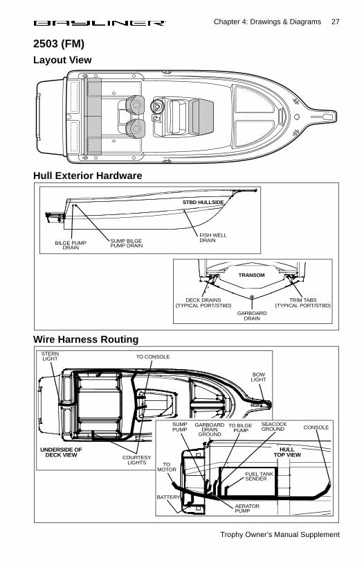
2503 (FM)Layout View
Hull Exterior Hardware
Wire Harness Routing
GARBOARDDRAIN
DECK DRAINS(TYPICAL PORT/STBD)
TRIM TABS(TYPICAL PORT/STBD)
TRANSOM
SUMP BILGE PUMP DRAINBILGE PUMP
DRAIN
FISH WELLDRAIN
STBD HULLSIDE
BOW
TO CONSOLE
COURTESY
STERN
LIGHTS
LIGHT
LIGHT
UNDERSIDE OFDECK VIEW
CONSOLE
FUEL TANKSENDER
SEACOCKGROUND
SUMP PUMP
BATTERY
AERATORPUMP
TO BILGE PUMP
GARBOARD
TOMOTOR
DRAINGROUND
HULLTOP VIEW
Trophy Owner’s Manual Supplement
28 Chapter 4: Drawings & Diagrams
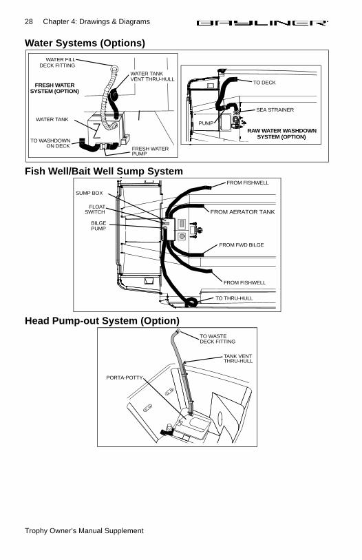
Water Systems (Options)
Fish Well/Bait Well Sump System
Head Pump-out System (Option)
WATER FILL
FRESH WATER
WATER TANKVENT THRU-HULL
WATER TANK
PUMP
DECK FITTING
TO WASHDOWNON DECK
FRESH WATERSYSTEM (OPTION)
SEA STRAINER
TO DECK
PUMP
RAW WATER WASHDOWNSYSTEM (OPTION)
FROM AERATOR TANK
FROM FWD BILGE
FROM FISHWELL
FROM FISHWELL
SUMP BOX
FLOAT
BILGE
SWITCH
PUMP
TO THRU-HULL
TO WASTEDECK FITTING
TANK VENTTHRU-HULL
PORTA-POTTY
Trophy Owner’s Manual Supplement
Chapter 4: Drawings & Diagrams 29
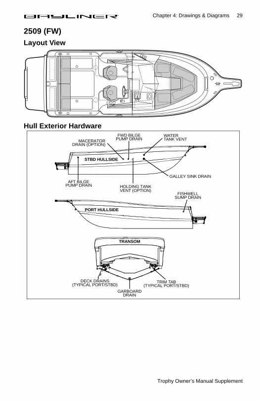
2509 (FW)Layout View
Hull Exterior Hardware
FISHWELLSUMP DRAIN
TRIM TAB(TYPICAL PORT/STBD)
GARBOARDDRAIN
(TYPICAL PORT/STBD)DECK DRAINS
AFT BILGEHOLDING TANK
FWD BILGEMACERATOR PUMP DRAIN
PUMP DRAIN
GALLEY SINK DRAIN
WATER
VENT (OPTION)
DRAIN (OPTION)TANK VENT
TRANSOM
STBD HULLSIDE
PORT HULLSIDE
Trophy Owner’s Manual Supplement
30 Chapter 4: Drawings & Diagrams
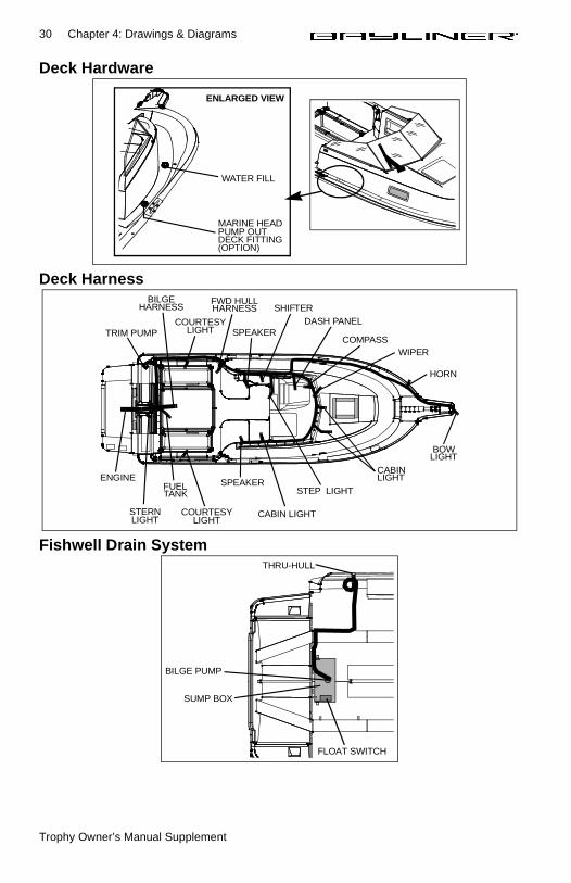
Deck Hardware
Deck Harness
Fishwell Drain System
MARINE HEADPUMP OUT
WATER FILL
DECK FITTING
ENLARGED VIEW
(OPTION)
DASH PANELCOURTESY
BOW
STERN
SHIFTER
SPEAKERENGINE
BILGE
FUEL
TRIM PUMP SPEAKER
FWD HULL
STEP LIGHT
CABIN
COURTESY
WIPERCOMPASS
HORN
CABIN LIGHT
LIGHT
HARNESS
LIGHTLIGHT
TANK
LIGHT
LIGHT
HARNESS
SUMP BOX
FLOAT SWITCH
BILGE PUMP
THRU-HULL
Trophy Owner’s Manual Supplement
Chapter 4: Drawings & Diagrams 31
Bait Well Pick-up System
Galley Water System
Marine Head (Option)
TO BAIT WELLTANK
HIGH SPEEDPICK-UP
PUMP TOAERATOR
BAIT WELLPUMP
HOSE COVER
WATER
WATER FILLDECK FITTING
TANK
HAND PUMPTANK VENTTHRU-HULL
SUMP BOX
HEAD
SEASTRAINER
HOLDING TANKVENT THRU-HULL
HOLDINGTANK
HEAD
Trophy Owner’s Manual Supplement
32 Chapter 4: Drawings & Diagrams
Macerator (Option)
Raw Water (Option)
Fresh Water Washdown System (Option)
DECK WASTEFITTING
MACERATORPUMP
TANK VENTTHRU-HULL
SEA STRAINERWASHDOWNPUMP
WASHDOWNOUTLET
TO WATER FILL
TO WASHDOWNON DECK
DECK FITTING
WATERTANK
PUMP
Trophy Owner’s Manual Supplement
Chapter 4: Drawings & Diagrams 33
2802 (FH)Layout View
Hull Exterior Hardware
(OPTION)
ANCHOR
BOW EYE
DRAIN COVER
SHOWERDRAIN
FWDBILGE PUMP
COCKPIT SINKDRAIN
MACERATORPUMP OUT
FUELVENT
HOLDINGTANK VENT
WATERTANK VENT
BAIT WELLDRAIN
AFT BILGEPUMP
FISHWELLDRAIN
AFT SINKDRAIN
SINK DRAINCOCKPIT
DRAINGALLEY SINK
GARBOARDDRAINTRIM
TABS
STERN EYE(TYPICAL PORT/STBD)
RIGGING TUBES
STBD HULLSIDE
PORT HULLSIDE
TRANSOM VIEW
Trophy Owner’s Manual Supplement
34 Chapter 4: Drawings & Diagrams
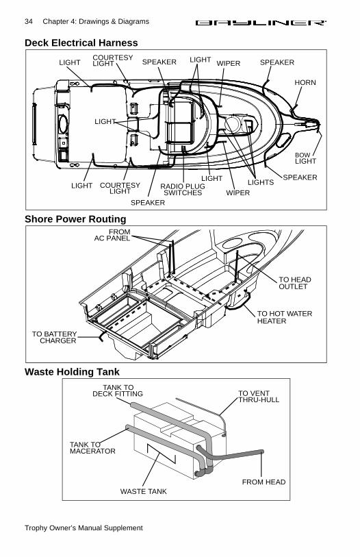
Deck Electrical Harness
Shore Power Routing
Waste Holding Tank
BOW
HORN
SPEAKER
SPEAKER
LIGHTLIGHT
LIGHT
LIGHT
SPEAKER
SPEAKERCOURTESYLIGHT
COURTESYLIGHT
RADIO PLUGSWITCHES WIPER
WIPER
LIGHT LIGHTS
LIGHT
FROMAC PANEL
TO BATTERY CHARGER
TO HOT WATERHEATER
TO HEADOUTLET
WASTE TANKFROM HEAD
TO VENTTHRU-HULL
TANK TOMACERATOR
TANK TODECK FITTING
Trophy Owner’s Manual Supplement
Chapter 4: Drawings & Diagrams 35
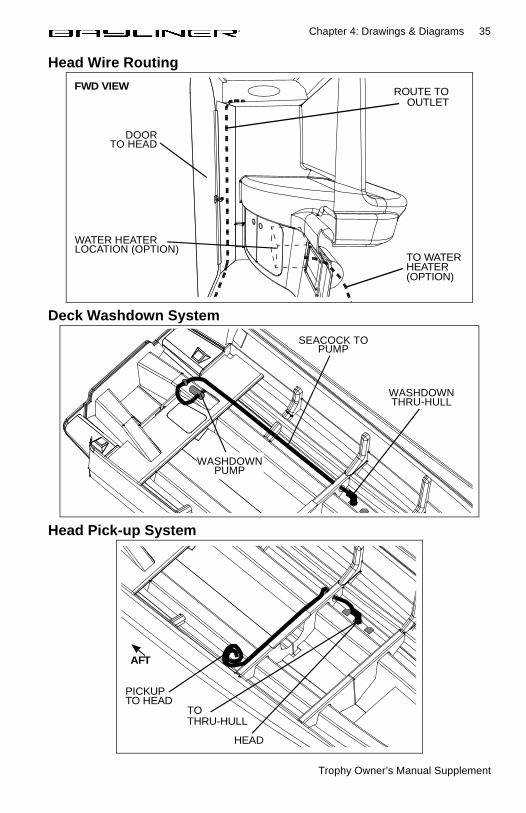
Head Wire Routing
Deck Washdown System
Head Pick-up System
FWD VIEW
TO WATERHEATER
ROUTE TOOUTLET
(OPTION)
WATER HEATERLOCATION (OPTION)
DOORTO HEAD
WASHDOWNTHRU-HULL
SEACOCK TOPUMP
WASHDOWNPUMP
TO
PICKUP
HEAD
TO HEAD
THRU-HULL
AFT
Trophy Owner’s Manual Supplement
36 Chapter 4: Drawings & Diagrams
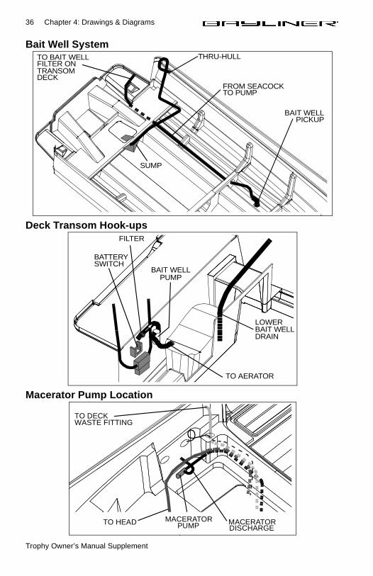
Bait Well System
Deck Transom Hook-ups
Macerator Pump Location
TO BAIT WELLFILTER ONTRANSOM
THRU-HULL
SUMP
DECKFROM SEACOCKTO PUMP
BAIT WELLPICKUP
FILTER
BAIT WELLPUMP
BATTERY
LOWER
TO AERATOR
BAIT WELLDRAIN
SWITCH
TO DECK WASTE FITTING
TO HEAD MACERATORPUMP MACERATOR
DISCHARGE
Trophy Owner’s Manual Supplement
Chapter 4: Drawings & Diagrams 37
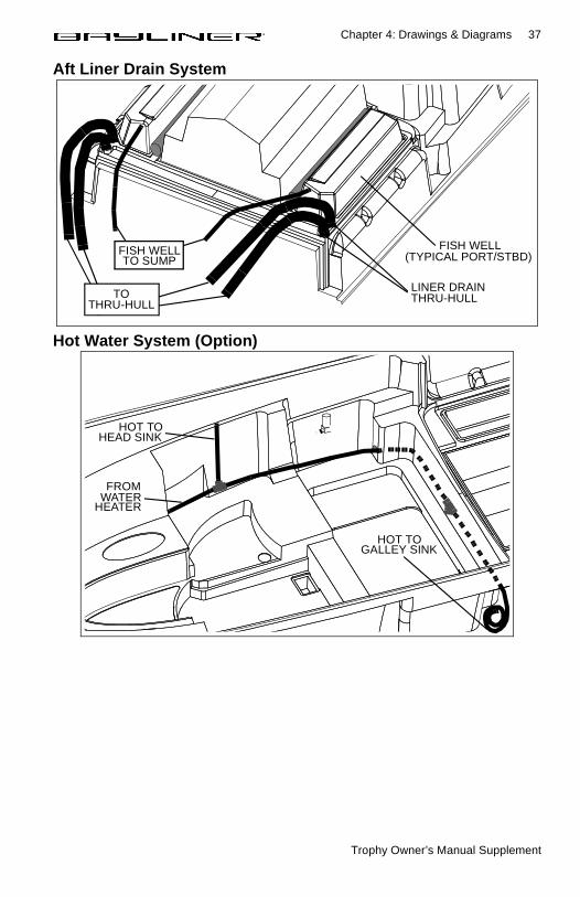
Aft Liner Drain System
Hot Water System (Option)
LINER DRAINTHRU-HULL
FISH WELL
TOTHRU-HULL
FISH WELLTO SUMP (TYPICAL PORT/STBD)
HOT TOHEAD SINK
FROMWATER
HEATER
HOT TOGALLEY SINK
Trophy Owner’s Manual Supplement
38
Chapter 5: Wiring Diagrams
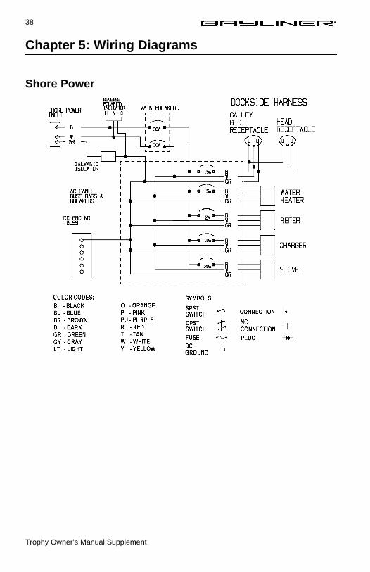
Shore Power
Trophy Owner’s Manual Supplement
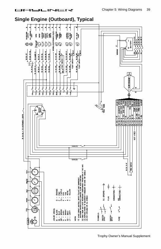
Chapter 5: Wiring Diagrams 39
Single Engine (Outboard), Typical
Trophy Owner’s Manual Supplement
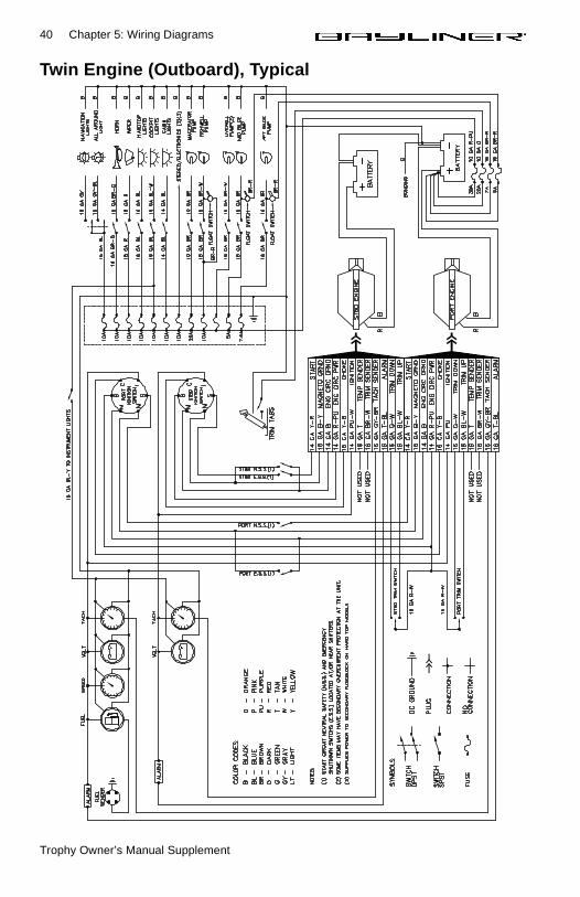
40 Chapter 5: Wiring Diagrams
Twin Engine (Outboard), Typical
Trophy Owner’s Manual Supplement
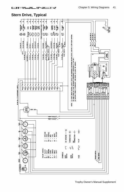
Chapter 5: Wiring Diagrams 41
Stern Drive, Typical
Trophy Owner’s Manual Supplement
42
Limited Warranty
Bayliner warrants to the original purchasers of its 1999 and 2000 model Trophys, purchased from an authorized dealer, operated under normal, noncommercial use that the selling dealer will: (A) Repair any structural hull defect which occurs within ten (10) years of the date of delivery; and (B) Repair or replace any parts found to be defective in factory material or workmanship within one (1) year of the date of delivery.
What Is Not CoveredThis limited warranty does not apply to:
1. Engines, drive trains, controls, props, batteries, or other equipment or accessories carrying their own individual warranties;
2. Engines, parts or accessories not installed by Bayliner;3. Plexiglass windscreen breakage; rainwater leakage on runabout models; rainwater leakage
through convertible tops; minor gelcoat discoloration, cracks or crazing or air voids;4. Hull blisters that form below the waterline;5. Normal deterioration, i.e. wear, tear, or corrosion of hardware, vinyl, tops, vinyl and fabric uphol-
stery, plastic, metal, wood, or trim tape;6. Any Bayliner boat which has been overpowered according to the maximum horsepower specifi-
cations on the capacity plate provided on each Bayliner outboard boat;7. Any Bayliner boat used for commercial purposes;8. Any defect caused by failure of the customer to provide reasonable care and maintenance.
Other LimitationsTHERE ARE NO OTHER EXPRESS WARRANTIES ON THIS BOAT. TO THE EXTENT ALLOWED BY LAW:
1. ANY IMPLIED WARRANTY OF MERCHANTABILITY OR FITNESS FOR A PARTICULAR PURPOSE IS LIMITED TO THE DURATION OF ONE YEAR.
2. Neither Bayliner nor the selling dealer shall have any responsibility for loss of use of the boat, loss of time, inconvenience, commercial loss or consequential damages.
3. Some jurisdictions do not allow limitations on how long any implied warranty lasts, so the above limitation may not apply to you. Some jurisdictions do not allow the exclusion or limitation of incidental or consequential damages, so the above limitation or exclusion may not apply to you. This limited warranty gives you specific legal rights, and you may also have other rights which vary from state to state.
Your ObligationIn order to comply with regulations, it is essential that your limited warranty registration card be submitted within 30 days of delivery of your boat. Return of the limited warranty registration card is a condition pre-cedent to limited warranty coverage. Before any warranty work is performed, we require that you contact your dealer to request warranty assistance.
YOU MUST GIVE US WRITTEN NOTICE OF YOUR WARRANTY CLAIM PRIOR TO THE EXPI-RATION OF YOUR LIMITED WARRANTY AND ALLOW US AN OPPORTUNITY TO RESOLVE THE MATTER.
We require that you return your boat, at your expense, to your selling dealer or, if necessary, to the Bay-liner factory. You will be responsible for all transportation, haulouts and other expenses incurred in return-ing the boat for warranty service.
Bayliner Marine CorporationPO Box 9029
Everett, WA 98206
Phone: 360-435-8957FAX: 360-403-4235

OWNER’S NOTES

OWNER’S NOTES


Part Number 1708205
A Brunswick Company
Bayliner • P.O. Box 9029 • Everett, WA 98206 • (360) 435-5571