Embed Size (px)
Citation preview
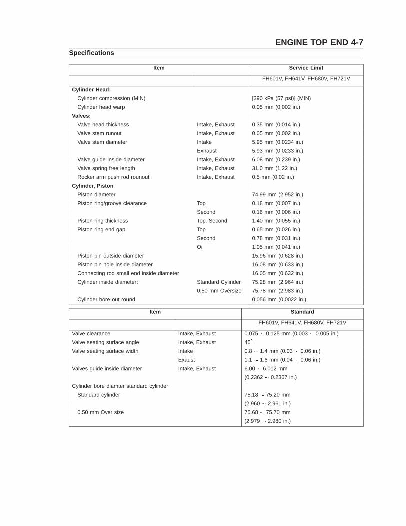
ENGINE TOP END 4-7Specifications
Item Service Limit
FH601V, FH641V, FH680V, FH721V
Cylinder Head:Cylinder compression (MIN) [390 kPa (57 psi)] (MIN)Cylinder head warp 0.05 mm (0.002 in.)
Valves:Valve head thickness Intake, Exhaust 0.35 mm (0.014 in.)Valve stem runout Intake, Exhaust 0.05 mm (0.002 in.)Valve stem diameter Intake 5.95 mm (0.0234 in.)
Exhaust 5.93 mm (0.0233 in.)Valve guide inside diameter Intake, Exhaust 6.08 mm (0.239 in.)Valve spring free length Intake, Exhaust 31.0 mm (1.22 in.)Rocker arm push rod rounout Intake, Exhaust 0.5 mm (0.02 in.)
Cylinder, PistonPiston diameter 74.99 mm (2.952 in.)Piston ring/groove clearance Top 0.18 mm (0.007 in.)
Second 0.16 mm (0.006 in.)Piston ring thickness Top, Second 1.40 mm (0.055 in.)Piston ring end gap Top 0.65 mm (0.026 in.)
Second 0.78 mm (0.031 in.)Oil 1.05 mm (0.041 in.)
Piston pin outside diameter 15.96 mm (0.628 in.)Piston pin hole inside diameter 16.08 mm (0.633 in.)Connecting rod small end inside diameter 16.05 mm (0.632 in.)Cylinder inside diameter: Standard Cylinder 75.28 mm (2.964 in.)
0.50 mm Oversize 75.78 mm (2.983 in.)Cylinder bore out round 0.056 mm (0.0022 in.)
Item Standard
FH601V, FH641V, FH680V, FH721V
Valve clearance Intake, Exhaust 0.075 0.125 mm (0.003 0.005 in.)Valve seating surface angle Intake, Exhaust 45�
Valve seating surface width Intake 0.8 1.4 mm (0.03 0.06 in.)Exaust 1.1 1.6 mm (0.04 0.06 in.)
Valves guide inside diameter Intake, Exhaust 6.00 6.012 mm(0.2362 0.2367 in.)
Cylinder bore diamter standard cylinderStandard cylinder 75.18 75.20 mm
(2.960 2.961 in.)0.50 mm Over size 75.68 75.70 mm
(2.979 2.980 in.)
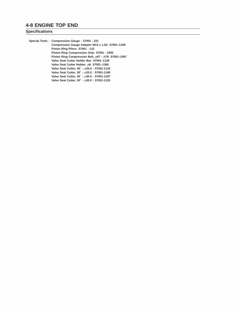
4-8 ENGINE TOP ENDSpecifications
Special Tools - Compression Gauge : 57001 - 221Compression Gauge Adapter M14 x 1.25: 57001–1159Piston Ring Pliers: 57001 - 115Piston Ring Compression Grip: 57001 - 1095Piston Ring Compression Belt, 67 - 79: 57001–1097Valve Seat Cutter Holder Bar: 57001–1128Valve Seat Cutter Holder, 6: 57001–1360Valve Seat Cutter, 45� - 35.0 : 57001-1116Valve Seat Cutter, 30� - 33.0 : 57001-1199Valve Seat Cutter, 45� - 30.0 : 57001-1187Valve Seat Cutter, 30� - 30.0 : 57001-1120
ENGINE TOP END 4-9Cylinder Head
Compression Measurement• Before measuring compression, do the following.� Be sure the battery is fully charged.� Thoroughly warm up the engine so that engine oil between the piston
and cylinder wall will help seal compression as it does during normalrunning.
� Stop the engine.• Disconnect the spark plug caps of each cylinder and remove the spark
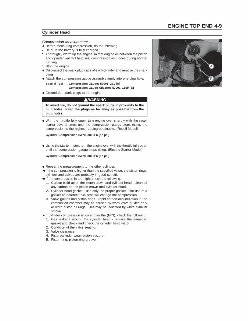
plugs.• Attach the compression gauge assembly firmly into one plug hole.
Special Tool - Compression Gauge: 57001–221 [A]Compression Gauge Adapter: 57001–1159 [B]
• Ground the spark plugs to the engine.
To avoid fire, do not ground the spark plugs in proximity to theplug holes. Keep the plugs as far away as possible from theplug holes.
• With the throttle fully open, turn engine over sharply with the recoilstarter several times until the compression gauge stops rising; thecompression is the highest reading obtainable. (Recoil Model)
Cylinder Compression (MIN) 390 kPa (57 psi)
• Using the starter motor, turn the engine over with the throttle fully openuntil the compression gauge stops rising; (Electric Starter Model).
Cylinder Compression (MIN) 390 kPa (57 psi)
• Repeat the measurement to the other cylinder.If the compression is higher than the specified value, the piston rings,cylinder and valves are probably in good condition.If the compression is too high, check the following.1. Carbon build-up on the piston crown and cylinder head - clean off
any carbon on the piston crown and cylinder head.2. Cylinder head gasket - use only the proper gasket. The use of a
gasket of incorrect thickness will change the compression.3. Valve guides and piston rings - rapid carbon accumulation in the
combustion chamber may be caused by worn valve guides and/or worn piston oil rings. This may be indicated by white exhaustsmoke.
If cylinder compression is lower than the (MIN), check the following:1. Gas leakage around the cylinder head - replace the damaged
gasket and check and check the cylinder head warp.2. Condition of the valve seating.3. Valve clearance.4. Piston/cylinder wear, piston seizure.5. Piston ring, piston ring groove.
4-10 ENGINE TOP ENDCylinder Head
Cylinder Head Assembly Removal• Remove:
Air Cleaner and Carburetor (see Fuel System chapter)Muffler (see Muffler Exhaust Pipe Removal)Intake Manifold (see Fuel System chapter)Spark Plug
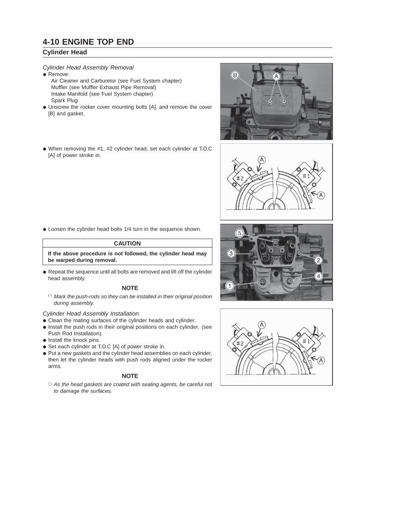
• Unscrew the rocker cover mounting bolts [A], and remove the cover[B] and gasket.
• When removing the #1, #2 cylinder head, set each cylinder at T.D.C[A] of power stroke in.
• Loosen the cylinder head bolts 1/4 turn in the sequence shown.
CAUTIONIf the above procedure is not followed, the cylinder head maybe warped during removal.
• Repeat the sequence until all bolts are removed and lift off the cylinderhead assembly.
NOTE� Mark the push-rods so they can be installed in their original position
during assembly.
Cylinder Head Assembly Installation• Clean the mating surfaces of the cylinder heads and cylinder.• Install the push rods in their original positions on each cylinder. (see
Push Rod Installation).• Install the knock pins.• Set each cylinder at T.D.C [A] of power stroke in.• Put a new gaskets and the cylinder head assemblies on each cylinder,
then let the cylinder heads with push rods aligned under the rockerarms.
NOTE� As the head gaskets are coated with sealing agents, be careful not
to damage the surfaces.
ENGINE TOP END 4-11Cylinder Head
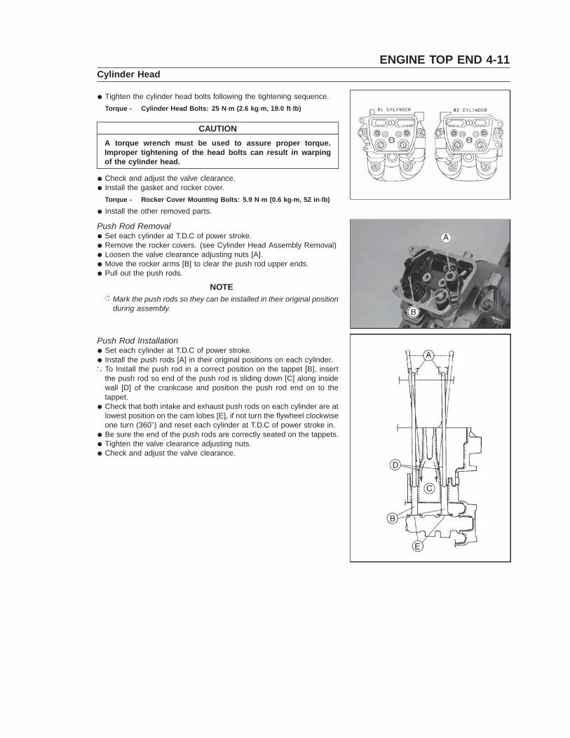
• Tighten the cylinder head bolts following the tightening sequence.Torque - Cylinder Head Bolts: 25 N�m (2.6 kg�m, 19.0 ft�lb)
CAUTIONA torque wrench must be used to assure proper torque.Improper tightening of the head bolts can result in warpingof the cylinder head.
• Check and adjust the valve clearance.• Install the gasket and rocker cover.
Torque - Rocker Cover Mounting Bolts: 5.9 N�m (0.6 kg�m, 52 in�lb)
• Install the other removed parts.
Push Rod Removal• Set each cylinder at T.D.C of power stroke.• Remove the rocker covers. (see Cylinder Head Assembly Removal)• Loosen the valve clearance adjusting nuts [A].• Move the rocker arms [B] to clear the push rod upper ends.• Pull out the push rods.
NOTE� Mark the push rods so they can be installed in their original position
during assembly.
Push Rod Installation• Set each cylinder at T.D.C of power stroke.• Install the push rods [A] in their original positions on each cylinder.� To Install the push rod in a correct position on the tappet [B], insert
the push rod so end of the push rod is sliding down [C] along insidewall [D] of the crankcase and position the push rod end on to thetappet.
• Check that both intake and exhaust push rods on each cylinder are atlowest position on the cam lobes [E], if not turn the flywheel clockwiseone turn (360�) and reset each cylinder at T.D.C of power stroke in.
• Be sure the end of the push rods are correctly seated on the tappets.• Tighten the valve clearance adjusting nuts.• Check and adjust the valve clearance.
4-12 ENGINE TOP ENDCylinder Head
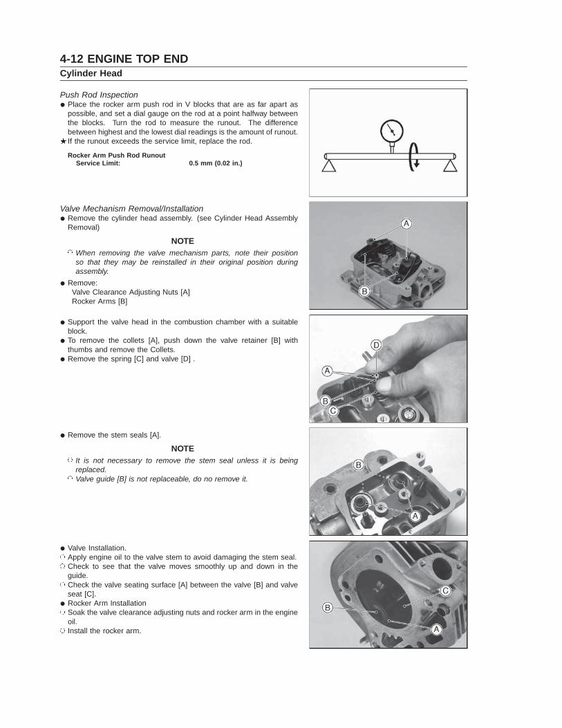
Push Rod Inspection• Place the rocker arm push rod in V blocks that are as far apart as
possible, and set a dial gauge on the rod at a point halfway betweenthe blocks. Turn the rod to measure the runout. The differencebetween highest and the lowest dial readings is the amount of runout.If the runout exceeds the service limit, replace the rod.
Rocker Arm Push Rod RunoutService Limit: 0.5 mm (0.02 in.)
Valve Mechanism Removal/Installation• Remove the cylinder head assembly. (see Cylinder Head Assembly
Removal)
NOTE� When removing the valve mechanism parts, note their position
so that they may be reinstalled in their original position duringassembly.
• Remove:Valve Clearance Adjusting Nuts [A]Rocker Arms [B]
• Support the valve head in the combustion chamber with a suitableblock.
• To remove the collets [A], push down the valve retainer [B] withthumbs and remove the Collets.
• Remove the spring [C] and valve [D] .
• Remove the stem seals [A].
NOTE� It is not necessary to remove the stem seal unless it is being
replaced.� Valve guide [B] is not replaceable, do no remove it.
• Valve Installation.� Apply engine oil to the valve stem to avoid damaging the stem seal.� Check to see that the valve moves smoothly up and down in the
guide.� Check the valve seating surface [A] between the valve [B] and valve
seat [C].• Rocker Arm Installation� Soak the valve clearance adjusting nuts and rocker arm in the engine
oil.� Install the rocker arm.
ENGINE TOP END 4-13Cylinder Head
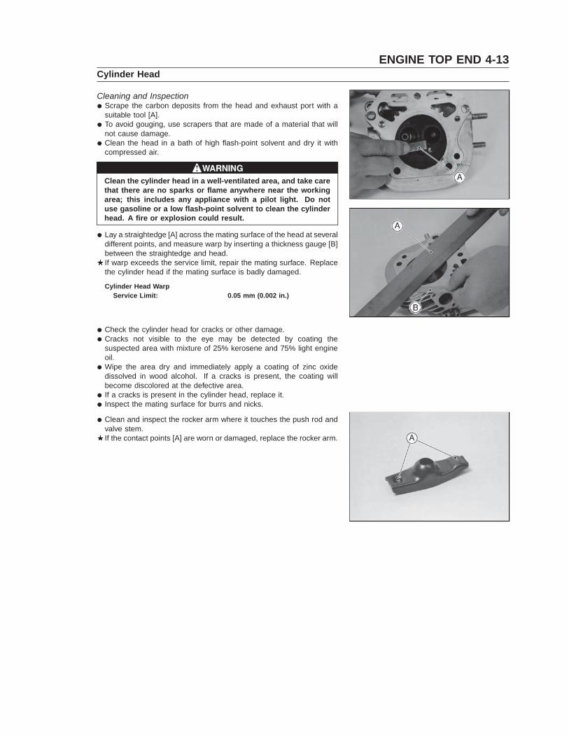
Cleaning and Inspection• Scrape the carbon deposits from the head and exhaust port with a
suitable tool [A].• To avoid gouging, use scrapers that are made of a material that will
not cause damage.• Clean the head in a bath of high flash-point solvent and dry it with
compressed air.
Clean the cylinder head in a well-ventilated area, and take carethat there are no sparks or flame anywhere near the workingarea; this includes any appliance with a pilot light. Do notuse gasoline or a low flash-point solvent to clean the cylinderhead. A fire or explosion could result.
• Lay a straightedge [A] across the mating surface of the head at severaldifferent points, and measure warp by inserting a thickness gauge [B]between the straightedge and head.If warp exceeds the service limit, repair the mating surface. Replacethe cylinder head if the mating surface is badly damaged.
Cylinder Head WarpService Limit: 0.05 mm (0.002 in.)
• Check the cylinder head for cracks or other damage.• Cracks not visible to the eye may be detected by coating the
suspected area with mixture of 25% kerosene and 75% light engineoil.
• Wipe the area dry and immediately apply a coating of zinc oxidedissolved in wood alcohol. If a cracks is present, the coating willbecome discolored at the defective area.
• If a cracks is present in the cylinder head, replace it.• Inspect the mating surface for burrs and nicks.
• Clean and inspect the rocker arm where it touches the push rod andvalve stem.If the contact points [A] are worn or damaged, replace the rocker arm.
4-14 ENGINE TOP ENDValves
Valve Clearance Inspection
NOTE� Valve clearance must be checked when the engine is cold (at room
temperature).
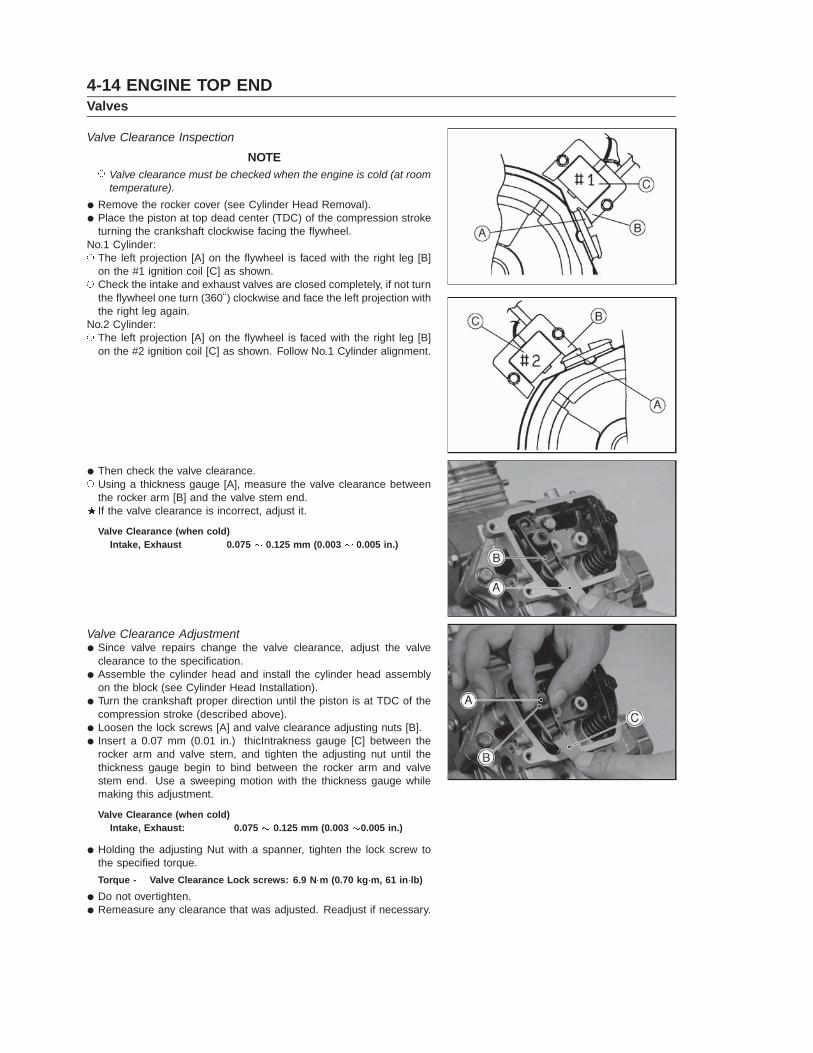
• Remove the rocker cover (see Cylinder Head Removal).• Place the piston at top dead center (TDC) of the compression stroke
turning the crankshaft clockwise facing the flywheel.No.1 Cylinder:� The left projection [A] on the flywheel is faced with the right leg [B]
on the #1 ignition coil [C] as shown.� Check the intake and exhaust valves are closed completely, if not turn
the flywheel one turn (360�) clockwise and face the left projection withthe right leg again.
No.2 Cylinder:� The left projection [A] on the flywheel is faced with the right leg [B]
on the #2 ignition coil [C] as shown. Follow No.1 Cylinder alignment.
• Then check the valve clearance.� Using a thickness gauge [A], measure the valve clearance between
the rocker arm [B] and the valve stem end.If the valve clearance is incorrect, adjust it.
Valve Clearance (when cold)Intake, Exhaust 0.075 0.125 mm (0.003 0.005 in.)
Valve Clearance Adjustment• Since valve repairs change the valve clearance, adjust the valve
clearance to the specification.• Assemble the cylinder head and install the cylinder head assembly
on the block (see Cylinder Head Installation).• Turn the crankshaft proper direction until the piston is at TDC of the
compression stroke (described above).• Loosen the lock screws [A] and valve clearance adjusting nuts [B].• Insert a 0.07 mm (0.01 in.) thicIntrakness gauge [C] between the
rocker arm and valve stem, and tighten the adjusting nut until thethickness gauge begin to bind between the rocker arm and valvestem end. Use a sweeping motion with the thickness gauge whilemaking this adjustment.
Valve Clearance (when cold)Intake, Exhaust: 0.075 0.125 mm (0.003 0.005 in.)
• Holding the adjusting Nut with a spanner, tighten the lock screw tothe specified torque.Torque - Valve Clearance Lock screws: 6.9 N�m (0.70 kg�m, 61 in�lb)
• Do not overtighten.• Remeasure any clearance that was adjusted. Readjust if necessary.

ENGINE TOP END 4-15Valves
Valve Seat Inspection• Remove the valve. (see Valve Mechanism Removal/Installation)• Inspect the valve seats for damage.
If the seats are warped or distorted beyond reconditioning, replacethe cylinder head.
• Pitted or worn valve seats can be refaced. Lap the valves to the seatsafter refacing.
• Coat the valve seat with machinist’s dye.• Push the valve into the guide.• Rotate the valve against the seat with a lapping tool.• Pull the valve out, and check the seating pattern on the valve head.
It must be the correct width [A] and even all the way around.
NOTE� The valve stem and guide must be in good condition or this check
will not be valid.If the valve seating pattern is not correct, repair the seat.
Valve Seating Surface Width (STD)[FH451V, FH500V, FH531V]
Inlet, Exhaust 0.6 0.9 mm (0.024 0.035 in.)[FH601V, FH641V, FH680V,FH721V]
Inlet 0.8 1.4 mm (0.03 0.05 in.)Exhaust 1.1 1.6 mm (0.04 0.06 in.)
Valve Seat Repair• Follow the manufacture’s instructions for use of valve seat cutters
Special ToolsIntake Valve:
Seat Cutter 45� - ø35.0 57001-1116
Outside Cutter 30�- ø33.0 57001-1199
Exhaust Valve:
Seat Cutter 45�- ø30.0 57001-1187
Outside Cutter 30�- ø30.0 57001-1120
Valve Seat Cutter Holder-ø6.0: 57001-1360
Valve Seat Cutter Holder Bar: 57001-1128
If the manufacture’s instructions are not available, use the followingprocedure.
4-16 ENGINE TOP ENDValves
Seat Cutter Operating Cares:1. This valve seat cutter is designed only for valve seat repair.
Therefore the cutter must not be used for other purposes.2. Do not drop or hit the valve seat cutter, or the diamond particles
may fall off.3. Do not fail to apply engine oil to the valve seat cutter before
grinding the seat surface. Also wash off ground particles stickingto the cutter with washing oil.
NOTE� Do not use a wire brush to remove the metal particles from the
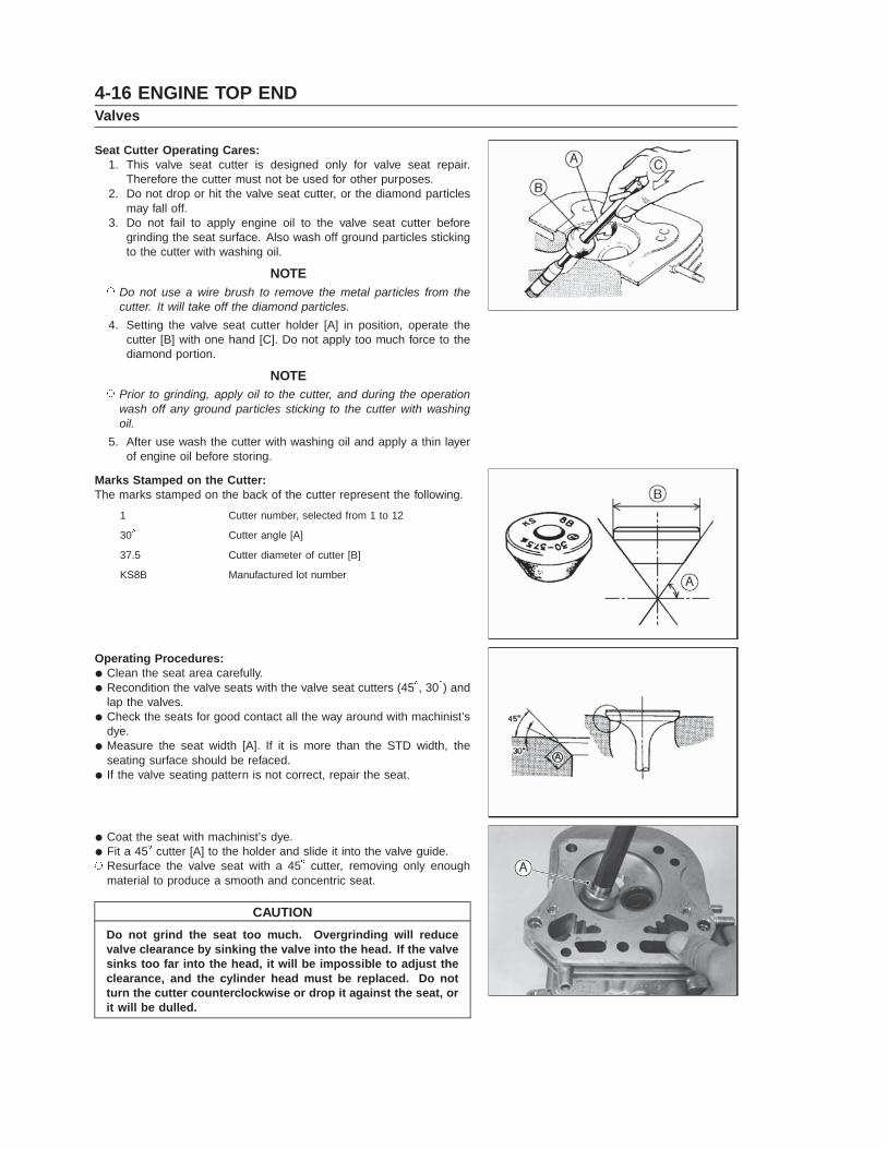
cutter. It will take off the diamond particles.4. Setting the valve seat cutter holder [A] in position, operate the
cutter [B] with one hand [C]. Do not apply too much force to thediamond portion.
NOTE� Prior to grinding, apply oil to the cutter, and during the operation
wash off any ground particles sticking to the cutter with washingoil.
5. After use wash the cutter with washing oil and apply a thin layerof engine oil before storing.
Marks Stamped on the Cutter:The marks stamped on the back of the cutter represent the following.
1 Cutter number, selected from 1 to 12
30� Cutter angle [A]
37.5 Cutter diameter of cutter [B]
KS8B Manufactured lot number
Operating Procedures:• Clean the seat area carefully.• Recondition the valve seats with the valve seat cutters (45�, 30�) and
lap the valves.• Check the seats for good contact all the way around with machinist’s
dye.• Measure the seat width [A]. If it is more than the STD width, the
seating surface should be refaced.• If the valve seating pattern is not correct, repair the seat.
• Coat the seat with machinist’s dye.• Fit a 45� cutter [A] to the holder and slide it into the valve guide.� Resurface the valve seat with a 45� cutter, removing only enough
material to produce a smooth and concentric seat.
CAUTIONDo not grind the seat too much. Overgrinding will reducevalve clearance by sinking the valve into the head. If the valvesinks too far into the head, it will be impossible to adjust theclearance, and the cylinder head must be replaced. Do notturn the cutter counterclockwise or drop it against the seat, orit will be dulled.
ENGINE TOP END 4-17Valves
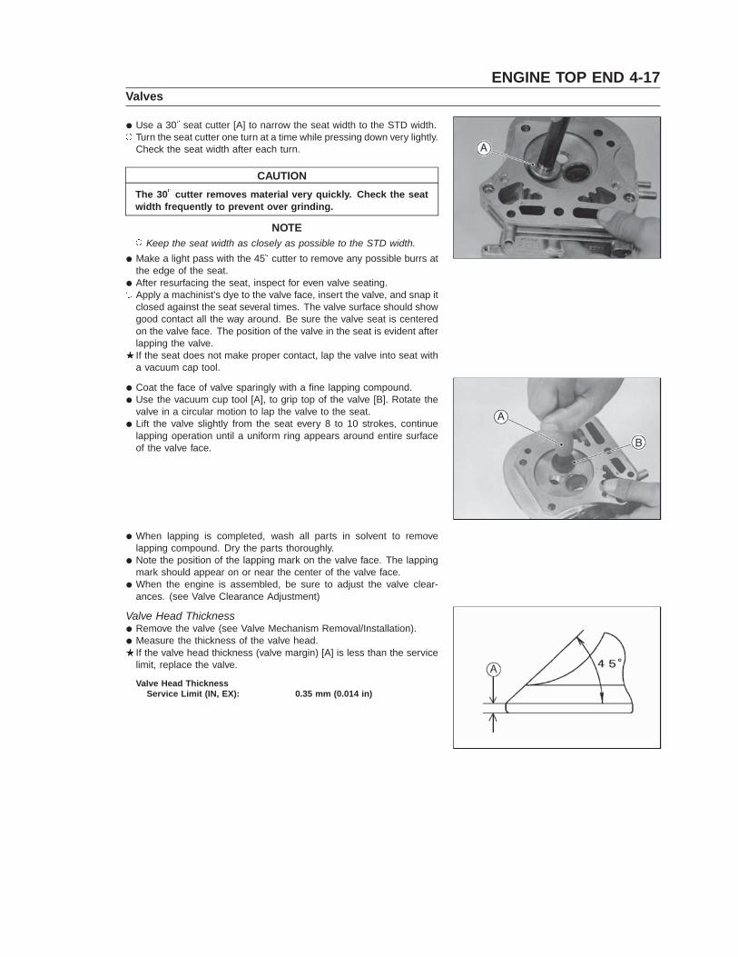
• Use a 30� seat cutter [A] to narrow the seat width to the STD width.� Turn the seat cutter one turn at a time while pressing down very lightly.
Check the seat width after each turn.
CAUTIONThe 30� cutter removes material very quickly. Check the seatwidth frequently to prevent over grinding.
NOTE� Keep the seat width as closely as possible to the STD width.
• Make a light pass with the 45� cutter to remove any possible burrs atthe edge of the seat.
• After resurfacing the seat, inspect for even valve seating.� Apply a machinist’s dye to the valve face, insert the valve, and snap it
closed against the seat several times. The valve surface should showgood contact all the way around. Be sure the valve seat is centeredon the valve face. The position of the valve in the seat is evident afterlapping the valve.If the seat does not make proper contact, lap the valve into seat witha vacuum cap tool.
• Coat the face of valve sparingly with a fine lapping compound.• Use the vacuum cup tool [A], to grip top of the valve [B]. Rotate the
valve in a circular motion to lap the valve to the seat.• Lift the valve slightly from the seat every 8 to 10 strokes, continue
lapping operation until a uniform ring appears around entire surfaceof the valve face.
• When lapping is completed, wash all parts in solvent to removelapping compound. Dry the parts thoroughly.
• Note the position of the lapping mark on the valve face. The lappingmark should appear on or near the center of the valve face.
• When the engine is assembled, be sure to adjust the valve clear-ances. (see Valve Clearance Adjustment)
Valve Head Thickness• Remove the valve (see Valve Mechanism Removal/Installation).• Measure the thickness of the valve head.
If the valve head thickness (valve margin) [A] is less than the servicelimit, replace the valve.
Valve Head ThicknessService Limit (IN, EX): 0.35 mm (0.014 in)
4-18 ENGINE TOP ENDValves
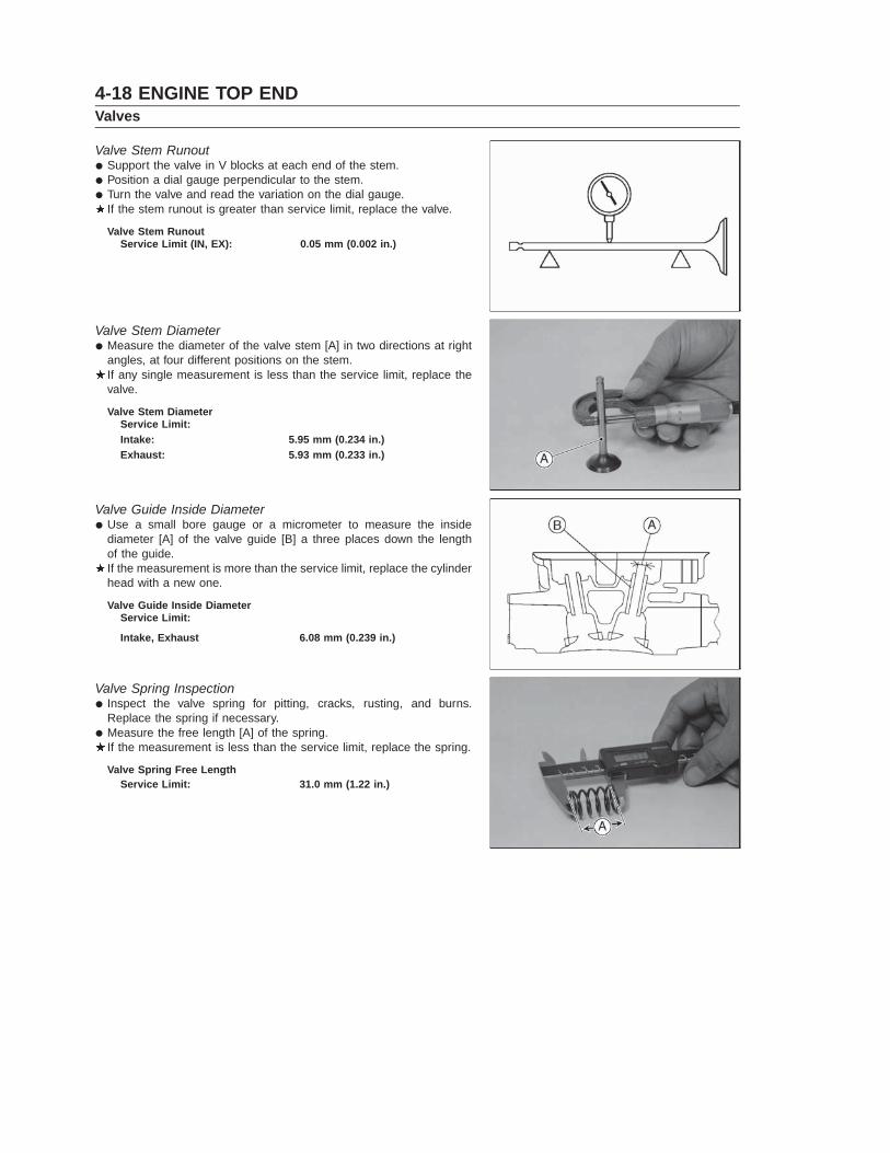
Valve Stem Runout• Support the valve in V blocks at each end of the stem.• Position a dial gauge perpendicular to the stem.• Turn the valve and read the variation on the dial gauge.
If the stem runout is greater than service limit, replace the valve.
Valve Stem RunoutService Limit (IN, EX): 0.05 mm (0.002 in.)
Valve Stem Diameter• Measure the diameter of the valve stem [A] in two directions at right
angles, at four different positions on the stem.If any single measurement is less than the service limit, replace thevalve.
Valve Stem DiameterService Limit:Intake: 5.95 mm (0.234 in.)Exhaust: 5.93 mm (0.233 in.)
Valve Guide Inside Diameter• Use a small bore gauge or a micrometer to measure the inside
diameter [A] of the valve guide [B] a three places down the lengthof the guide.If the measurement is more than the service limit, replace the cylinderhead with a new one.
Valve Guide Inside DiameterService Limit:
Intake, Exhaust 6.08 mm (0.239 in.)
Valve Spring Inspection• Inspect the valve spring for pitting, cracks, rusting, and burns.
Replace the spring if necessary.• Measure the free length [A] of the spring.
If the measurement is less than the service limit, replace the spring.
Valve Spring Free LengthService Limit: 31.0 mm (1.22 in.)