Embed Size (px)
Citation preview
24-1
24Engineered Cementitious
Composite (ECC):Material, Structural, andDurability Performance
Victor C. Li, Ph.D., FASCE, FASME, FWIF*
24.1 Historical Development ....................................................24-124.2 General Characteristics .....................................................24-4
The Family of ECC Materials • Tensile Characteristics • ECC Material Design Considerations • Compressive and Flexural Characteristics
24.3 Mixture Proportioning, Material Processing, and Quality Control..........................................................24-8
24.4 Behavior of ECC Structural Elements ...........................24-12Structural Response of R/ECC Elements • Insights from R/ECC Element Response
24.5 Durability of ECC and ECC Structural Elements ........24-24Material and Element Durability • ECC Durability under Various Environments • Durability of R/ECC • Long-Term Performance
24.6 Concluding Remarks.......................................................24-37Acknowledgments......................................................................24-40References ...................................................................................24-40
24.1 Historical Development
The development of fiber-reinforced concrete material has undergone a number of phases. In the 1960s,research by Romualdi and coworkers (Romualdi and Batson, 1963; Romualdi and Mandel, 1964) dem-onstrated the effectiveness of short steel fibers in reducing the brittleness of concrete. This developmenthas continued with expansion to a variety of other fibers, such as glass, carbon, synthetics, natural fibers,and, in recent years, hybrids that combine either different fiber types or fiber lengths. The continuouslyenhanced knowledge of fiber-reinforcement effectiveness has resulted in structural design recommenda-tions by RILEM TC 162-TDF (Vandewalle et al., 2003). This document focuses on fiber-reinforced
* E. Benjamin Wylie Collegiate Chair Professor, Department of Civil and Environmental Engineering, University ofMichigan, Ann Arbor; expert on high-performance fiber-reinforced cementitious composites, inventor of engineeredcementitious composites.
© 2008 by Taylor & Francis Group, LLC
24-2 Concrete Construction Engineering Handbook
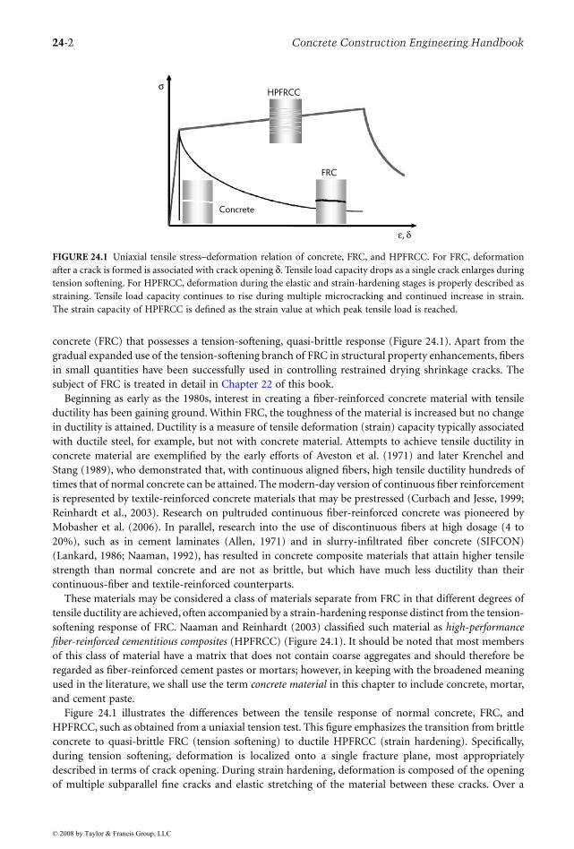
concrete (FRC) that possesses a tension-softening, quasi-brittle response (Figure 24.1). Apart from thegradual expanded use of the tension-softening branch of FRC in structural property enhancements, fibersin small quantities have been successfully used in controlling restrained drying shrinkage cracks. Thesubject of FRC is treated in detail in Chapter 22 of this book.
Beginning as early as the 1980s, interest in creating a fiber-reinforced concrete material with tensileductility has been gaining ground. Within FRC, the toughness of the material is increased but no changein ductility is attained. Ductility is a measure of tensile deformation (strain) capacity typically associatedwith ductile steel, for example, but not with concrete material. Attempts to achieve tensile ductility inconcrete material are exemplified by the early efforts of Aveston et al. (1971) and later Krenchel andStang (1989), who demonstrated that, with continuous aligned fibers, high tensile ductility hundreds oftimes that of normal concrete can be attained. The modern-day version of continuous fiber reinforcementis represented by textile-reinforced concrete materials that may be prestressed (Curbach and Jesse, 1999;Reinhardt et al., 2003). Research on pultruded continuous fiber-reinforced concrete was pioneered byMobasher et al. (2006). In parallel, research into the use of discontinuous fibers at high dosage (4 to20%), such as in cement laminates (Allen, 1971) and in slurry-infiltrated fiber concrete (SIFCON)(Lankard, 1986; Naaman, 1992), has resulted in concrete composite materials that attain higher tensilestrength than normal concrete and are not as brittle, but which have much less ductility than theircontinuous-fiber and textile-reinforced counterparts.
These materials may be considered a class of materials separate from FRC in that different degrees oftensile ductility are achieved, often accompanied by a strain-hardening response distinct from the tension-softening response of FRC. Naaman and Reinhardt (2003) classified such material as high-performancefiber-reinforced cementitious composites (HPFRCC) (Figure 24.1). It should be noted that most membersof this class of material have a matrix that does not contain coarse aggregates and should therefore beregarded as fiber-reinforced cement pastes or mortars; however, in keeping with the broadened meaningused in the literature, we shall use the term concrete material in this chapter to include concrete, mortar,and cement paste.
Figure 24.1 illustrates the differences between the tensile response of normal concrete, FRC, andHPFRCC, such as obtained from a uniaxial tension test. This figure emphasizes the transition from brittleconcrete to quasi-brittle FRC (tension softening) to ductile HPFRCC (strain hardening). Specifically,during tension softening, deformation is localized onto a single fracture plane, most appropriatelydescribed in terms of crack opening. During strain hardening, deformation is composed of the openingof multiple subparallel fine cracks and elastic stretching of the material between these cracks. Over a
FIGURE 24.1 Uniaxial tensile stress–deformation relation of concrete, FRC, and HPFRCC. For FRC, deformationafter a crack is formed is associated with crack opening δ. Tensile load capacity drops as a single crack enlarges duringtension softening. For HPFRCC, deformation during the elastic and strain-hardening stages is properly described asstraining. Tensile load capacity continues to rise during multiple microcracking and continued increase in strain.The strain capacity of HPFRCC is defined as the strain value at which peak tensile load is reached.
FRC
HPFRCCσ
ε, δ
Concrete
© 2008 by Taylor & Francis Group, LLC
Engineered Cementitious Composites 24-3
length scale that includes many such cracks, the deformation may be considered tensile strain smearedover a representative volume of material. As will be seen in the following sections, these distinctionsbetween FRC and HPFRCC have significant ramifications in terms of load capacity and structuraldurability.
Whereas the HPFRCC materials mentioned above embody the highly desired tensile properties lackingin normal concrete or in FRC, until recently they have mostly been limited to academic research labo-ratories or specialized applications. This is due to additional demands in industrial projects, particularlyin on-site construction, such as economical feasibility and constructability. These two demands aredifficult to meet when either continuous fibers or high fiber content are used in the composites.
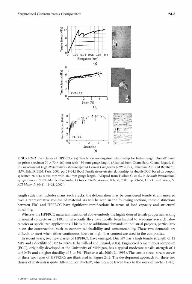
In recent years, two new classes of HPFRCC have emerged. Ductal® has a high tensile strength of 12MPa and a ductility of 0.02 to 0.06% (Chanvillard and Rigaud, 2003). Engineered cementitious composite(ECC), originally developed at the University of Michigan, has a typical moderate tensile strength of 4to 6 MPa and a higher ductility of 3 to 5% (Fischer et al., 2003; Li, 1993). The tensile stress–strain curvesof these two types of HPFRCCs are illustrated in Figure 24.2. The development approach for these twoclasses of materials is quite different. For Ductal®, which can be traced back to the work of Bache (1981),
FIGURE 24.2 Two classes of HPFRCCs: (a) Tensile stress-elongation relationship for high-strength Ductal® basedon prism specimen 70 × 70 × 160 mm with 150-mm gauge length. (Adapted from Chanvillard, G. and Rigaud, S.,in Proceedings of High-Performance Fiber-Reinforced Cement Composites (HPFRCC 4), Naaman, A.E. and Reinhardt,H.W., Eds., RILEM, Paris, 2003, pp. 21–34.) (b, c) Tensile stress–strain relationship for ductile ECC, based on couponspecimen 76 × 13 × 305 mm with 180-mm gauge length. (Adapted from Fischer, G. et al., in Seventh InternationalSymposium on Brittle Matrix Composites, October 13–15, Warsaw, Poland, 2003, pp. 29–36; Li, V.C. and Wang, S.,ACI Mater. J., 99(1), 11–21, 2002.)
12
8
4
00 0.02 0.04 0.06 0.08 0.1
Te
nsi
le S
tre
ss (
MPa
)T
en
sile
Str
ess
(M
Pa)
Te
nsi
le S
tre
ss (
MPa
)Elongation (mm)
(a)
PVA-ECC
8
6
4
2
00 1 2 3 4 5
Strain (%)
(b)
8
6
4
2
00 1 2 3 4
PE-ECC
Strain (%)
(c)
20
mm
20
mm
20
mm
© 2008 by Taylor & Francis Group, LLC
24-4 Concrete Construction Engineering Handbook
the approach is to employ a tightly packed dense matrix to increase both tensile and compressive strengthof the material. Fiber is added to counteract the resulting high brittleness of the densified matrix. Thedense matrix allows a strong bond with the fiber that results in a high post-cracking strength as long asa fiber with high strength is utilized. For ECC, the approach is to create synergistic interactions betweenthe fiber, matrix, and interface to maximize the tensile ductility through development of closely spacedmultiple microcracks while minimizing the fiber content (generally 2% or less by volume). This approachis detailed in Section 24.2.3. Ductal® is designed for use in the elastic stage, so the fiber action becomeseffective only when the structural ultimate limit state (ULS) is approached. ECC is generally designedfor use in the elastic and strain-hardening (inelastic) stages, so fiber action becomes effective even undernormal service loads. The development of ECC is still evolving, even though a number of full-scalestructural applications have already appeared in Japan, Europe, and the United States. This chaptersummarizes some basic knowledge of ECC. In the following, the fundamental characteristics of ECC aredescribed. This is followed by a section on structural behavior of steel-reinforced ECC elements (R/ECC)and a section on the durability behavior of ECC material and R/ECC.
The literature on ECC is rapidly expanding with contributions from academic research and industrialorganizations around the world. Some good sources of references include recent workshop or conferenceproceedings on this subject, such as HPFRCC in Structural Applications (Fischer and Li, 2006), FraMCoS-6 (Carpinteri et al., 2007), and HPFRCC 5 (Reinhardt and Naaman, 2007). These documents contain anumber of papers on ECC and related subjects. To assist in the transition to broader industrial use, theJapan Society of Civil Engineers has published a design guideline (JSCE, 2007; Rokugo et al., 2007), andthe RILEM TC HFC technical committee will be publishing two state-of-the-art reports on this subject.To aid the reader in maneuvering this literature, some clarification on semantics will be helpful. Thename engineered cementitious composite (ECC) was adopted by the original developers (Li, 1993) toemphasize the micromechanics basis behind the design of this material. Micromechanics serves as apowerful tool to guide materials design for targeted composite properties and enables meaningful linkagebetween materials engineering and structure performance design (Li, 2007). In 2006, the RILEM TCHFC technical committee decided to emphasize the unique tensile strain-hardening response of thismaterial (Figure 24.1) as a constitutive law for structural engineering design and gave the more descriptivename strain-hardening cementitious composite (SHCC) to this class of materials. The Japan Society ofCivil Engineers, however, prefers to emphasize the multiple fine cracking (and associated durability; seeSection 24.5), thus they refer to the material as multiple fine cracking fiber-reinforced cementitious com-posite. In essence, all of these materials are designed using micromechanical tools and represent identicalmaterial technology.
24.2 General Characteristics
24.2.1 The Family of ECC Materials
Engineered cementitious composite can be regarded as a family of materials with a range of tensilestrengths and ductilities that can be adjusted depending on the demands of a particular structure. ECCalso represents a family of materials with different functionalities in addition to the common character-istics of high tensile ductility and fine multiple cracking. Self-consolidating ECC (e.g., ECC M45 and itsvariants) is designed for large-scale, on-site construction applications (Kong et al., 2003; Lepech and Li,2007). High-early-strength ECC (HES-ECC) is designed for applications that require rapid strength gain,such as transportation infrastructure that must be quickly reopened to the motorist public (Wang andLi, 2006a). Lightweight ECC (LW-ECC) is designed for applications where the dead load of structuralmembers must be minimized (Wang and Li, 2003). Green ECC (G-ECC) is designed to maximize materialgreenness and infrastructure sustainability (Lepech et al., 2007; Li et al., 2004b). Self-healing ECC (SH-ECC) emphasizes the functionality of recovering transport and mechanical properties after experiencingdamage (Li and Yang, 2007; Yang et al., 2005).
© 2008 by Taylor & Francis Group, LLC
Engineered Cementitious Composites 24-5
Engineered cementitious composite using local material ingredients has been successfully producedin various countries, including Japan (Kanda et al., 2006a,b), Europe (Mechtcherine and Schulze, 2006),and South Africa (Boshoff and van Zijl, 2007), in addition to the United States. To successfully developlocal versions of ECC, a good understanding of the underlying design approach is helpful (Kanda andLi, 1999; Li, 1993). A synopsis of the ECC design approach is given in Section 24.2.3.
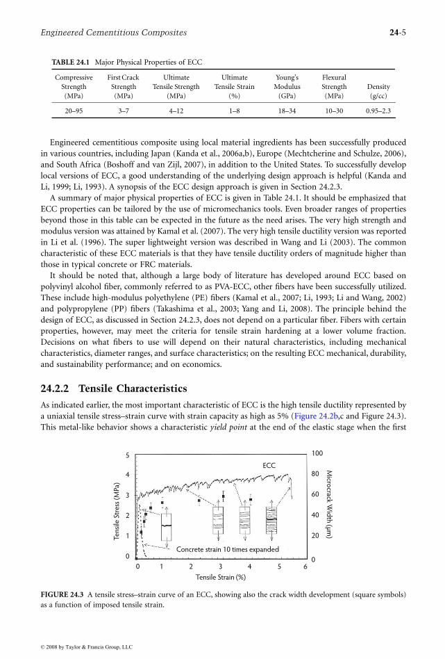
A summary of major physical properties of ECC is given in Table 24.1. It should be emphasized thatECC properties can be tailored by the use of micromechanics tools. Even broader ranges of propertiesbeyond those in this table can be expected in the future as the need arises. The very high strength andmodulus version was attained by Kamal et al. (2007). The very high tensile ductility version was reportedin Li et al. (1996). The super lightweight version was described in Wang and Li (2003). The commoncharacteristic of these ECC materials is that they have tensile ductility orders of magnitude higher thanthose in typical concrete or FRC materials.
It should be noted that, although a large body of literature has developed around ECC based onpolyvinyl alcohol fiber, commonly referred to as PVA-ECC, other fibers have been successfully utilized.These include high-modulus polyethylene (PE) fibers (Kamal et al., 2007; Li, 1993; Li and Wang, 2002)and polypropylene (PP) fibers (Takashima et al., 2003; Yang and Li, 2008). The principle behind thedesign of ECC, as discussed in Section 24.2.3, does not depend on a particular fiber. Fibers with certainproperties, however, may meet the criteria for tensile strain hardening at a lower volume fraction.Decisions on what fibers to use will depend on their natural characteristics, including mechanicalcharacteristics, diameter ranges, and surface characteristics; on the resulting ECC mechanical, durability,and sustainability performance; and on economics.
24.2.2 Tensile Characteristics
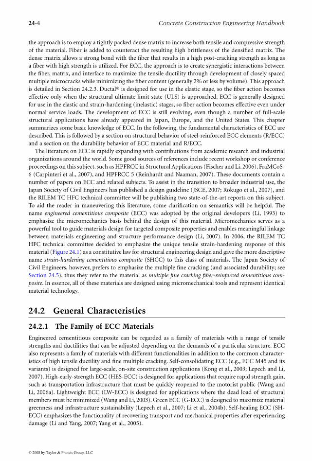
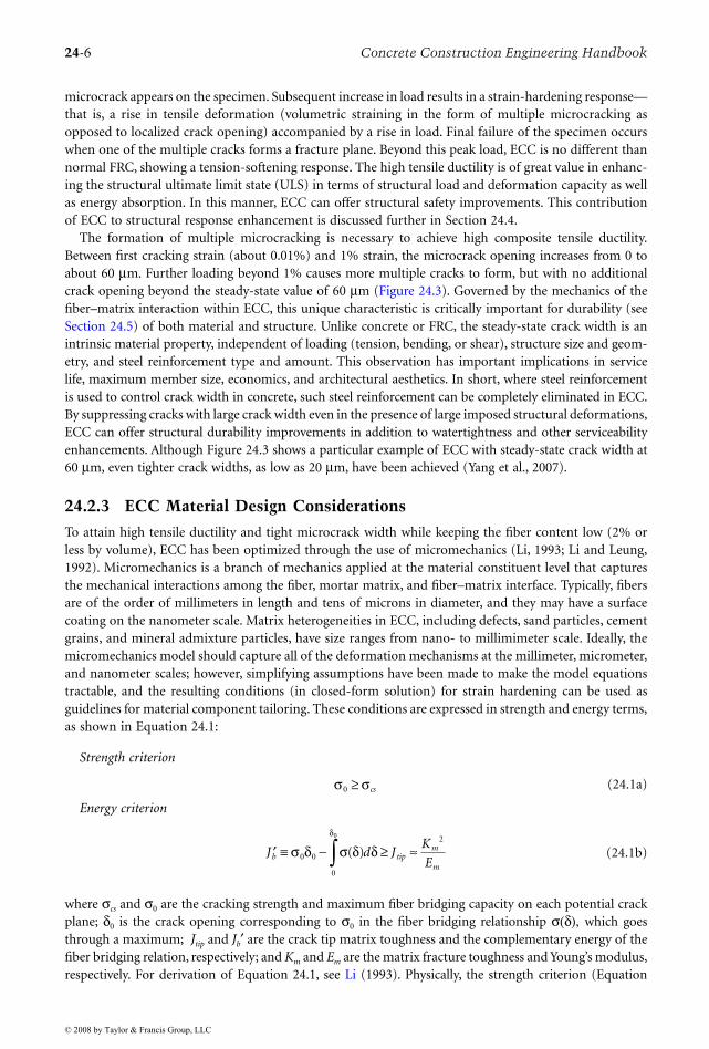
As indicated earlier, the most important characteristic of ECC is the high tensile ductility represented bya uniaxial tensile stress–strain curve with strain capacity as high as 5% (Figure 24.2b,c and Figure 24.3).This metal-like behavior shows a characteristic yield point at the end of the elastic stage when the first
TABLE 24.1 Major Physical Properties of ECC
CompressiveStrength (MPa)
First Crack Strength (MPa)
UltimateTensile Strength
(MPa)
Ultimate Tensile Strain
(%)
Young’s Modulus
(GPa)
Flexural Strength (MPa)
Density(g/cc)
20–95 3–7 4–12 1–8 18–34 10–30 0.95–2.3
FIGURE 24.3 A tensile stress–strain curve of an ECC, showing also the crack width development (square symbols)as a function of imposed tensile strain.
0 1 2 3 4 5 6
Tensile Strain (%)
5
4
3
2
1
0
Te
nsi
le S
tre
ss (
MPa
)
100
80
60
40
20
0
Micro
crack Wid
th (µ
m)
Concrete strain 10 times expanded
ECC
© 2008 by Taylor & Francis Group, LLC
24-6 Concrete Construction Engineering Handbook
microcrack appears on the specimen. Subsequent increase in load results in a strain-hardening response—that is, a rise in tensile deformation (volumetric straining in the form of multiple microcracking asopposed to localized crack opening) accompanied by a rise in load. Final failure of the specimen occurswhen one of the multiple cracks forms a fracture plane. Beyond this peak load, ECC is no different thannormal FRC, showing a tension-softening response. The high tensile ductility is of great value in enhanc-ing the structural ultimate limit state (ULS) in terms of structural load and deformation capacity as wellas energy absorption. In this manner, ECC can offer structural safety improvements. This contributionof ECC to structural response enhancement is discussed further in Section 24.4.
The formation of multiple microcracking is necessary to achieve high composite tensile ductility.Between first cracking strain (about 0.01%) and 1% strain, the microcrack opening increases from 0 toabout 60 µm. Further loading beyond 1% causes more multiple cracks to form, but with no additionalcrack opening beyond the steady-state value of 60 µm (Figure 24.3). Governed by the mechanics of thefiber–matrix interaction within ECC, this unique characteristic is critically important for durability (seeSection 24.5) of both material and structure. Unlike concrete or FRC, the steady-state crack width is anintrinsic material property, independent of loading (tension, bending, or shear), structure size and geom-etry, and steel reinforcement type and amount. This observation has important implications in servicelife, maximum member size, economics, and architectural aesthetics. In short, where steel reinforcementis used to control crack width in concrete, such steel reinforcement can be completely eliminated in ECC.By suppressing cracks with large crack width even in the presence of large imposed structural deformations,ECC can offer structural durability improvements in addition to watertightness and other serviceabilityenhancements. Although Figure 24.3 shows a particular example of ECC with steady-state crack width at60 µm, even tighter crack widths, as low as 20 µm, have been achieved (Yang et al., 2007).
24.2.3 ECC Material Design Considerations
To attain high tensile ductility and tight microcrack width while keeping the fiber content low (2% orless by volume), ECC has been optimized through the use of micromechanics (Li, 1993; Li and Leung,1992). Micromechanics is a branch of mechanics applied at the material constituent level that capturesthe mechanical interactions among the fiber, mortar matrix, and fiber–matrix interface. Typically, fibersare of the order of millimeters in length and tens of microns in diameter, and they may have a surfacecoating on the nanometer scale. Matrix heterogeneities in ECC, including defects, sand particles, cementgrains, and mineral admixture particles, have size ranges from nano- to millimimeter scale. Ideally, themicromechanics model should capture all of the deformation mechanisms at the millimeter, micrometer,and nanometer scales; however, simplifying assumptions have been made to make the model equationstractable, and the resulting conditions (in closed-form solution) for strain hardening can be used asguidelines for material component tailoring. These conditions are expressed in strength and energy terms,as shown in Equation 24.1:
Strength criterion
(24.1a)
Energy criterion
(24.1b)
where σcs and σ0 are the cracking strength and maximum fiber bridging capacity on each potential crackplane; δ0 is the crack opening corresponding to σ0 in the fiber bridging relationship σ(δ), which goesthrough a maximum; Jtip and Jb′ are the crack tip matrix toughness and the complementary energy of thefiber bridging relation, respectively; and Km and Em are the matrix fracture toughness and Young’s modulus,respectively. For derivation of Equation 24.1, see Li (1993). Physically, the strength criterion (Equation
σ σ0 ≥ cs
′ ≡ − ≥ ≈∫J d JK
Eb tip
m
m
σ δ σ δ δδ
0 0
0
20
( )
© 2008 by Taylor & Francis Group, LLC
Engineered Cementitious Composites 24-7
24.1a) ensures the initiation of microcracks from initial flaw sites in the composite before the tensile loadexceeds the maximum fiber bridging capacity. The left-hand side of Equation 24.1a can be thought of asthe maximum tensile load carried by a line of springs with tensile strength determined by the bridgingfibers. Failure of the fiber springs is associated with fiber rupture, slippage, or pullout. Ensuring that themaximum fiber bridging capacities on existing crack planes remain higher than the matrix crackingstrength of potential new crack planes allows additional cracks to form; otherwise, saturated multiplecracking would not be attained, and sparsely spaced cracks will result, limiting the tensile ductility.
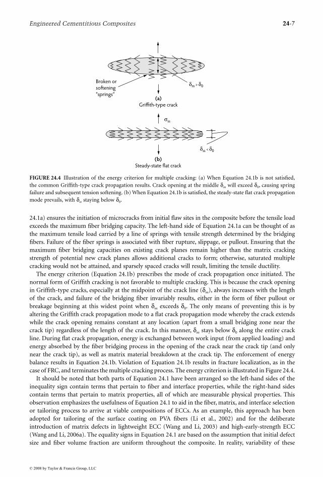
The energy criterion (Equation 24.1b) prescribes the mode of crack propagation once initiated. Thenormal form of Griffith cracking is not favorable to multiple cracking. This is because the crack openingin Griffith-type cracks, especially at the midpoint of the crack line (δm), always increases with the lengthof the crack, and failure of the bridging fiber invariably results, either in the form of fiber pullout orbreakage beginning at this widest point when δm exceeds δ0. The only means of preventing this is byaltering the Griffith crack propagation mode to a flat crack propagation mode whereby the crack extendswhile the crack opening remains constant at any location (apart from a small bridging zone near thecrack tip) regardless of the length of the crack. In this manner, δm stays below δ0 along the entire crackline. During flat crack propagation, energy is exchanged between work input (from applied loading) andenergy absorbed by the fiber bridging process in the opening of the crack near the crack tip (and onlynear the crack tip), as well as matrix material breakdown at the crack tip. The enforcement of energybalance results in Equation 24.1b. Violation of Equation 24.1b results in fracture localization, as in thecase of FRC, and terminates the multiple cracking process. The energy criterion is illustrated in Figure 24.4.
It should be noted that both parts of Equation 24.1 have been arranged so the left-hand sides of theinequality sign contain terms that pertain to fiber and interface properties, while the right-hand sidescontain terms that pertain to matrix properties, all of which are measurable physical properties. Thisobservation emphasizes the usefulness of Equation 24.1 to aid in the fiber, matrix, and interface selectionor tailoring process to arrive at viable compositions of ECCs. As an example, this approach has beenadopted for tailoring of the surface coating on PVA fibers (Li et al., 2002) and for the deliberateintroduction of matrix defects in lightweight ECC (Wang and Li, 2003) and high-early-strength ECC(Wang and Li, 2006a). The equality signs in Equation 24.1 are based on the assumption that initial defectsize and fiber volume fraction are uniform throughout the composite. In reality, variability of these
FIGURE 24.4 Illustration of the energy criterion for multiple cracking: (a) When Equation 24.1b is not satisfied,the common Griffith-type crack propagation results. Crack opening at the middle δm will exceed δ0, causing springfailure and subsequent tension softening. (b) When Equation 24.1b is satisfied, the steady-state flat crack propagationmode prevails, with δss staying below δ0.
(a)
Griffith-type crack
(b)
Steady-state flat crack
σss
δss < δ0
Broken or
softening
“springs”
δm > δ0
© 2008 by Taylor & Francis Group, LLC
24-8 Concrete Construction Engineering Handbook
parameters must exist and depends on the mix composition as well as mixing procedure. This variabilitycreates the need for a wider margin between the left- and right-hand sides of Equation 24.1 and explainsthe use of the inequality signs. Kanda and Li (2006) specifically studied the necessary margin to createrobust tensile properties.
24.2.4 Compressive and Flexural Characteristics
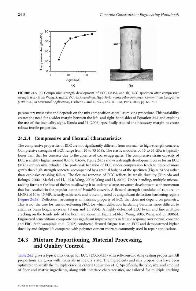
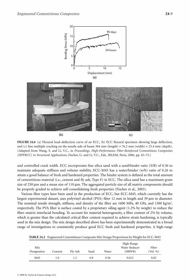
The compressive properties of ECC are not significantly different from normal- to high-strength concrete.Compressive strengths of ECC range from 20 to 95 MPa. The elastic modulus of 15 to 34 GPa is typicallylower than that for concrete due to the absence of coarse aggregates. The compressive strain capacity ofECC is slightly higher, around 0.45 to 0.65%. Figure 24.5a shows a strength development curve for an ECC(M45) compressive cylinder. The post-peak behavior of ECC under compression tends to descend moregently than high-strength concrete, accompanied by a gradual bulging of the specimen (Figure 24.5b) ratherthan explosive crushing failure. The flexural response of ECC reflects its tensile ductility (Kunieda andRokugo, 2006a; Maalej and Li, 1994; Wang, 2005; Wang and Li, 2006). Under bending, multiple microc-racking forms at the base of the beam, allowing it to undergo a large curvature development, a phenomenonthat has resulted in the popular name of bendable concrete. A flexural strength (modulus of rupture, orMOR) of 10 to 15 MPa is easily achievable and is accompanied by a significant deflection-hardening regime(Figure 24.6a). Deflection hardening is an intrinsic property of ECC that does not depend on geometry.This is not the case for tension-softening FRC, for which deflection hardening becomes more difficult toattain as beam height increases (Stang and Li, 2004). A highly deformed ECC beam and fine multiplecracking on the tensile side of the beam are shown in Figure 24.6b,c (Wang, 2005; Wang and Li, 2006b).Engineered cementitious composite has significant improvements in fatigue response over normal concreteand FRC. Suthiwarapirak et al. (2002) conducted flexural fatigue tests on ECC and demonstrated higherductility and fatigue life compared with polymer cement mortars commonly used in repair applications.
24.3 Mixture Proportioning, Material Processing, and Quality Control
Table 24.2 gives a typical mix design for ECC (ECC-M45) with self-consolidating casting properties. Allproportions are given with materials in the dry state. The ingredients and mix proportions have beenoptimized to satisfy the multiple cracking criteria (Equation 24.1). Specifically, the type, size, and amountof fiber and matrix ingredients, along with interface characteristics, are tailored for multiple cracking
FIGURE 24.5 (a) Compressive strength development of ECC (M45), and (b) ECC specimen after compressivestrength test. (From Wang, S. and Li, V.C., in Proceedings, High-Performance Fiber-Reinforced Cementitious Composites(HPFRCC) in Structural Applications, Fischer, G. and Li, V.C., Eds., RILEM, Paris, 2006, pp. 65–73.)
80
60
40
20
01 10 100
Age (days)
(a) (b)
Co
mp
ress
ive
Str
en
gth
(M
Pa)
© 2008 by Taylor & Francis Group, LLC
Engineered Cementitious Composites 24-9
and controlled crack width. ECC incorporates fine silica sand with a sand/binder ratio (S/B) of 0.36 tomaintain adequate stiffness and volume stability. ECC-M45 has a water/binder (w/b) ratio of 0.26 toattain a good balance of fresh and hardened properties. The binder system is defined as the total amountof cementitious material (i.e., cement and fly ash, Type F) in ECC. The silica sand has a maximum grainsize of 250 µm and a mean size of 110 µm. The aggregated particle size of all matrix components shouldbe properly graded to achieve self-consolidating fresh properties (Fischer et al., 2003).
Various fiber types have been used in the production of ECC, but ECC-M45, which currently has thelargest experimental dataset, uses polyvinyl alcohol (PVA) fiber 12 mm in length and 39 µm in diameter.The nominal tensile strength, stiffness, and density of the fiber are 1600 MPa, 40 GPa, and 1300 kg/m3,respectively. The PVA fiber is surface coated by a proprietary oiling agent (1.2% by weight) to reduce thefiber–matrix interfacial bonding. To account for material heterogeneity, a fiber content of 2% by volume,which is greater than the calculated critical fiber content required to achieve strain hardening, is typicallyused in the mix design. The mix design described above has been experimentally demonstrated in a broadrange of investigations to consistently produce good ECC fresh and hardened properties. A high-range
FIGURE 24.6 (a) Flexural load–deflection curve of an ECC, (b) ECC flexural specimen showing large deflection,and (c) fine multiple cracking on the tensile side of beam 304 mm (length) × 76.2 mm (width) × 25.4 mm (depth).(Adapted from Wang, S. and Li, V.C., in Proceedings, High-Performance Fiber-Reinforced Cementitious Composites(HPFRCC) in Structural Applications, Fischer, G. and Li, V.C., Eds., RILEM, Paris, 2006, pp. 65–73.)
TABLE 24.2 Engineered Cementitious Composite Mix Design Proportions by Weight for ECC-M45
Mix Designation Cement Fly Ash Sand Water
High-Range Water Reducer
(HRWR)Fiber
(Vol. %)
M45 1.0 1.2 0.8 0.56 0.012 0.02
(b)
2 cm
(c)
0 5 10 15
24 hours
90 days
Displacement (mm)
(a)
Be
nd
ing
Str
ess
(M
Pa)
20
15
10
5
0
2 cm
© 2008 by Taylor & Francis Group, LLC
24-10 Concrete Construction Engineering Handbook
water-reducing (HRWR) admixture containing a polycarboxylate chemical composition has been found tobe most effective in maintaining the desired fresh property during mixing and placing. Adaptations of thisreference mix have been used in various construction projects. Full-scale production of ECC was carriedout in Japan (Kunieda and Rokugo, 2006b) and in the United States (Lepech and Li, 2007). Experience inconcrete ready-mix plants suggests the charging sequence of raw material shown in Table 24.3.
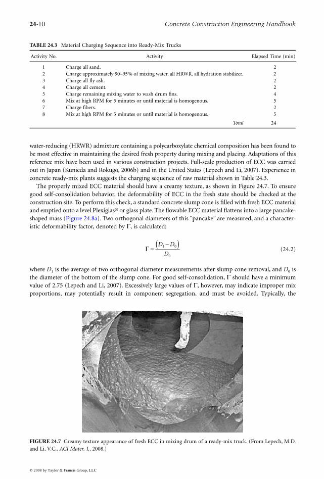
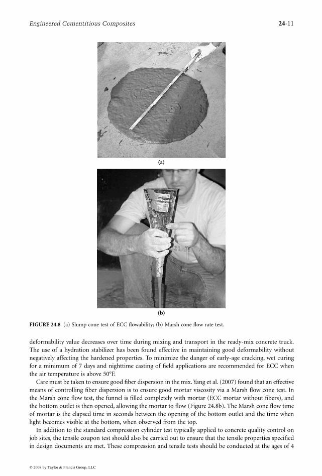
The properly mixed ECC material should have a creamy texture, as shown in Figure 24.7. To ensuregood self-consolidation behavior, the deformability of ECC in the fresh state should be checked at theconstruction site. To perform this check, a standard concrete slump cone is filled with fresh ECC materialand emptied onto a level Plexiglas® or glass plate. The flowable ECC material flattens into a large pancake-shaped mass (Figure 24.8a). Two orthogonal diameters of this “pancake” are measured, and a character-istic deformability factor, denoted by Γ, is calculated:
(24.2)
where D1 is the average of two orthogonal diameter measurements after slump cone removal, and D0 isthe diameter of the bottom of the slump cone. For good self-consolidation, Γ should have a minimumvalue of 2.75 (Lepech and Li, 2007). Excessively large values of Γ, however, may indicate improper mixproportions, may potentially result in component segregation, and must be avoided. Typically, the
TABLE 24.3 Material Charging Sequence into Ready-Mix Trucks
Activity No. Activity Elapsed Time (min)
1 Charge all sand. 22 Charge approximately 90–95% of mixing water, all HRWR, all hydration stabilizer. 23 Charge all fly ash. 24 Charge all cement. 25 Charge remaining mixing water to wash drum fins. 46 Mix at high RPM for 5 minutes or until material is homogenous. 57 Charge fibers. 28 Mix at high RPM for 5 minutes or until material is homogenous. 5
Total 24
FIGURE 24.7 Creamy texture appearance of fresh ECC in mixing drum of a ready-mix truck. (From Lepech, M.D.and Li, V.C., ACI Mater. J., 2008.)
Γ =−( )D D
D1 0
0
© 2008 by Taylor & Francis Group, LLC
Engineered Cementitious Composites 24-11
deformability value decreases over time during mixing and transport in the ready-mix concrete truck.The use of a hydration stabilizer has been found effective in maintaining good deformability withoutnegatively affecting the hardened properties. To minimize the danger of early-age cracking, wet curingfor a minimum of 7 days and nighttime casting of field applications are recommended for ECC whenthe air temperature is above 50°F.
Care must be taken to ensure good fiber dispersion in the mix. Yang et al. (2007) found that an effectivemeans of controlling fiber dispersion is to ensure good mortar viscosity via a Marsh flow cone test. Inthe Marsh cone flow test, the funnel is filled completely with mortar (ECC mortar without fibers), andthe bottom outlet is then opened, allowing the mortar to flow (Figure 24.8b). The Marsh cone flow timeof mortar is the elapsed time in seconds between the opening of the bottom outlet and the time whenlight becomes visible at the bottom, when observed from the top.
In addition to the standard compression cylinder test typically applied to concrete quality control onjob sites, the tensile coupon test should also be carried out to ensure that the tensile properties specifiedin design documents are met. These compression and tensile tests should be conducted at the ages of 4
FIGURE 24.8 (a) Slump cone test of ECC flowability; (b) Marsh cone flow rate test.
(a)
(b)
© 2008 by Taylor & Francis Group, LLC
24-12 Concrete Construction Engineering Handbook
days, 7 days, 14 days, and 28 days to observe property development over time. It is recognized thatuniaxial tension tests are difficult to carry out on a routine quality control basis. As a result, a simplerbending test accompanied by inversion schemes to obtain material tensile properties is being developed(Kanakubo, 2006; Qian and Li, 2007).
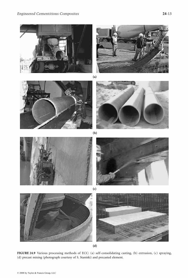
Apart from ready-mix and self-consolidating casting, special versions of ECC have also been developedfor extrusion (Stang and Li, 1999) and shotcreting (Kanda et al., 2001; Kim et al., 2003; Kojima et al.,2004). Precasting of ECC structural elements has been utilized for coupling beams in high-rise buildingsin Japan (Kanda et al., 2006a,b). Kanda et al. concluded that full-scale production in a precast plant ofECC with high mechanical performance and excellent fluidity is achievable in practice. Figure 24.9 showsthe various methods of ECC material processing. Although these ECC materials all carry the samehardened material characteristics described in Section 24.2, they exhibit significantly different freshproperties to meet different processing requirements. The relatively small amount of fibers used in ECCallows such versatility in processing methods.
24.4 Behavior of ECC Structural Elements
A variety of experiment programs have been performed to assess the performance of ECC at the structuralelement level for both seismic and non-seismic structural applications (Table 24.4). These experimentsprovide insight into how unique ECC material properties elevate the response performance of thestructure. Within this section, we describe some observed responses of elements subjected to monotonicand fatigue flexural loading, cyclic shear loading, and steel–ECC interactions. Fundamental knowledgewill then be drawn from these studies.
24.4.1 Structural Response of R/ECC Elements24.4.1.1 Flexural Elements
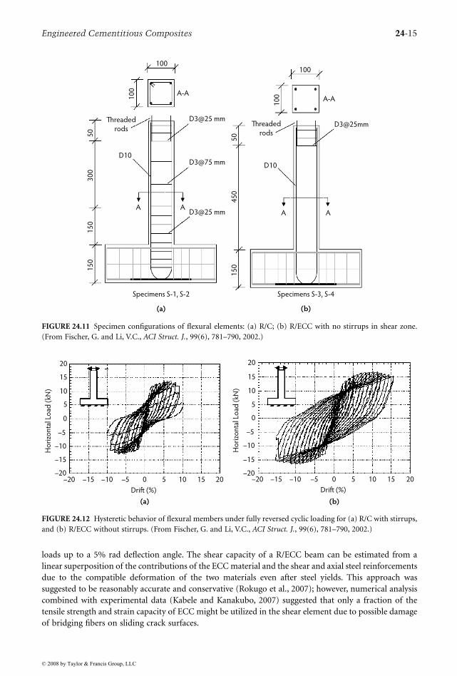
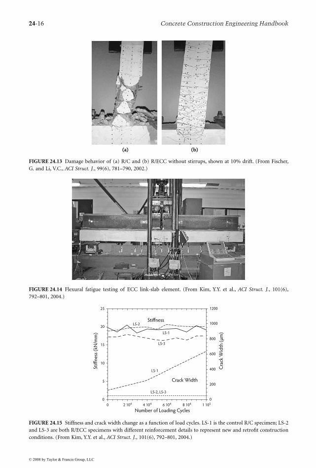
Fischer and Li (2002a) studied the behavior of R/ECC flexural elements under reversed cyclic loading. Thetest setup is shown in Figure 24.10, and the specimen configuration is shown in Figure 24.11. A regularreinforced-concrete (R/C) beam was also tested as control. Figure 24.12 shows the substantial differencein hysteretic response for the R/ECC and the R/C control column specimens. A significantly fuller hystereticloop with larger energy dissipation was achieved by the R/ECC beam despite the fact that no shear stirrupswere used at the base of the flexural element. The damage experienced by these elements at 10% interstorydrift is compared in Figure 24.13. Even at this high drift level, no spalling of the ECC was observed. Incontrast, the R/C column lost all concrete cover near the fixed end subsequent to bond splitting andspalling. Clearly, the R/ECC element demonstrated significant damage tolerance under severe loading.
The high cycle fatigue response of R/ECC flexural elements was studied by Kim et al. (2004) inconjunction with a bridge deck link slab application. The full-thickness slab test configuration is providedin Figure 24.14, which shows the steel girder (anchored to the slab by steel studs) on top for convenienceof testing. Over 100,000 cycles, no degradation in stiffness was observed in the R/ECC or in the R/Ccontrol beam; however, the cracks in the R/C beam grew continuously to 0.6 mm at the end of the test,while the microcracks in R/ECC beam remained at approximately 50 µm (Figure 24.15).
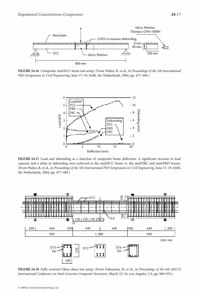
Motivated by the need to increase the stiffness and to reduce the tendency for fatigue cracking in steelbridge decks, a steel/ECC composite beam was studied by Walter et al. (2004) under monotonic flexuralloading (Figure 24.16). For control, a steel/FRC and a steel/FRD composite beam were also tested in thesame configuration. FRD is a fiber-reinforced Densit® material, a very high strength and dense concretereinforced with steel fibers similar to Ductal®. All concrete materials were cast onto the steel plate andbonded only by adhesion to the roughened steel surface. The load-deflection response captured in Figure24.17 demonstrates a much higher load capacity in the case of the steel/ECC beam, which showed multiplemicrocracking during testing, suppressing the formation of a brittle fracture that limits the capacity ofthe steel/concrete beam. The single fracture in the FRC and FRD beams led to their immediate debondingfrom the steel plate.
© 2008 by Taylor & Francis Group, LLC
Engineered Cementitious Composites 24-13
FIGURE 24.9 Various processing methods of ECC: (a) self-consolidating casting, (b) extrusion, (c) spraying,(d) precast mixing (photograph courtesy of S. Staniski) and precasted element.
(a)
(b)
(c)
(d)
© 2008 by Taylor & Francis Group, LLC
24-14 Concrete Construction Engineering Handbook
24.4.1.2 Shear Element
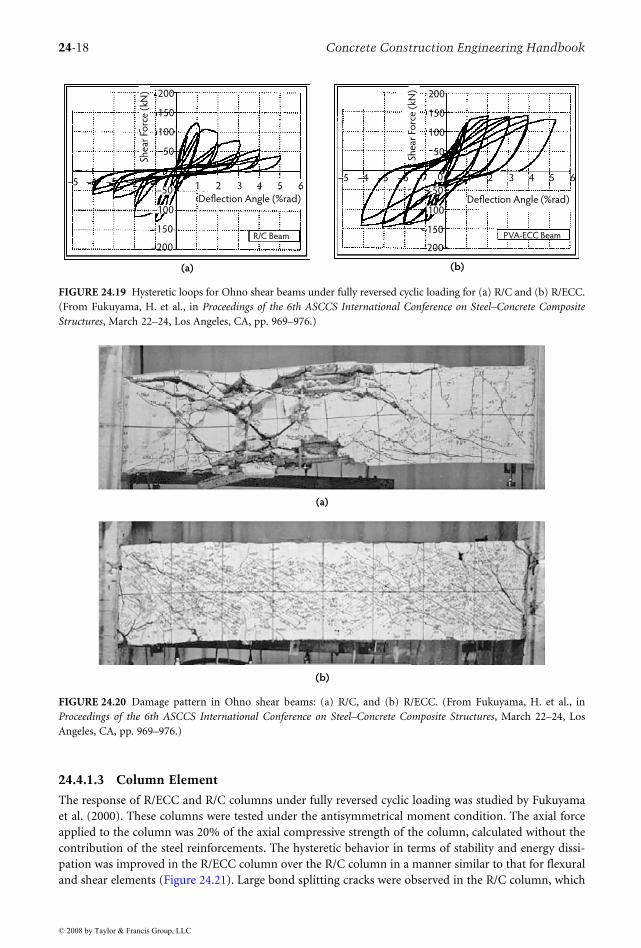
Fukuyama et al. (2000) studied the behavior of R/ECC shear elements under reversed cyclic loading. Thespecimen configuration is shown in Figure 24.18, and the hysteretic loops for R/ECC and R/C are shownin Figure 24.19. Again, the hysteretic loops for R/ECC showed much greater stability and ability todissipate energy. The R/C specimen suffered extensive bond splitting and loss of cover, accompanied bylarge diagonal cracks. In contrast, the damage experienced by the R/ECC shear element was significantlylower (Figure 24.20). No bond splitting or cover loss was observed, and microcracks continued to carry
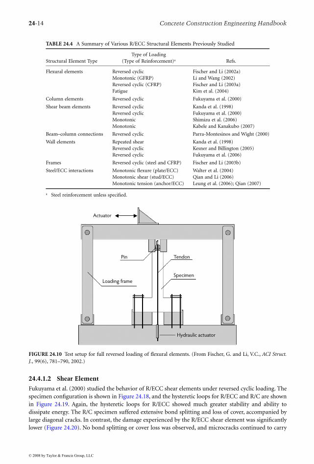
TABLE 24.4 A Summary of Various R/ECC Structural Elements Previously Studied
Structural Element TypeType of Loading
(Type of Reinforcement)a Refs.
Flexural elements Reversed cyclicMonotonic (GFRP)Reversed cyclic (CFRP)Fatigue
Fischer and Li (2002a)Li and Wang (2002)Fischer and Li (2003a)Kim et al. (2004)
Column elements Reversed cyclic Fukuyama et al. (2000)
Shear beam elements Reversed cyclicReversed cyclicMonotonicMonotonic
Kanda et al. (1998)Fukuyama et al. (2000)Shimizu et al. (2006)Kabele and Kanakubo (2007)
Beam–column connections Reversed cyclic Parra-Montesinos and Wight (2000)
Wall elements Repeated shearReversed cyclicReversed cyclic
Kanda et al. (1998)Kesner and Billington (2005)Fukuyama et al. (2006)
Frames Reversed cyclic (steel and CFRP) Fischer and Li (2003b)
Steel/ECC interactions Monotonic flexure (plate/ECC)Monotonic shear (stud/ECC)Monotonic tension (anchor/ECC)
Walter et al. (2004)Qian and Li (2006)Leung et al. (2006); Qian (2007)
a Steel reinforcement unless specified.
FIGURE 24.10 Test setup for full reversed loading of flexural elements. (From Fischer, G. and Li, V.C., ACI Struct.J., 99(6), 781–790, 2002.)
Actuator
Pin
Loading frame
Tendon
Specimen
Hydraulic actuator
© 2008 by Taylor & Francis Group, LLC
Engineered Cementitious Composites 24-15
loads up to a 5% rad deflection angle. The shear capacity of a R/ECC beam can be estimated from alinear superposition of the contributions of the ECC material and the shear and axial steel reinforcementsdue to the compatible deformation of the two materials even after steel yields. This approach wassuggested to be reasonably accurate and conservative (Rokugo et al., 2007); however, numerical analysiscombined with experimental data (Kabele and Kanakubo, 2007) suggested that only a fraction of thetensile strength and strain capacity of ECC might be utilized in the shear element due to possible damageof bridging fibers on sliding crack surfaces.
FIGURE 24.11 Specimen configurations of flexural elements: (a) R/C; (b) R/ECC with no stirrups in shear zone.(From Fischer, G. and Li, V.C., ACI Struct. J., 99(6), 781–790, 2002.)
FIGURE 24.12 Hysteretic behavior of flexural members under fully reversed cyclic loading for (a) R/C with stirrups,and (b) R/ECC without stirrups. (From Fischer, G. and Li, V.C., ACI Struct. J., 99(6), 781–790, 2002.)
100
10
0Threaded
rods
A-A
D3@25 mmD3@25mm
D3@75 mm
D3@25 mm
D10
50
50
45
01
50
30
01
50
15
0
Specimens S-1, S-2
(a) (b)
A AA A
Specimens S-3, S-4
D10
Threaded
rods
100
10
0 A-A
–20 –15 –10 –5 0 5 10 15 20
20
15
10
5
0
–5
–10
–15
–20
Ho
rizo
nta
l Lo
ad (
kN)
Ho
rizo
nta
l Lo
ad (
kN)
Drift (%)
20
15
10
5
0
–5
–10
–15
–20–20 –15 –10 –5 0 5 10 15 20
(a)
Drift (%)
(b)
© 2008 by Taylor & Francis Group, LLC
24-16 Concrete Construction Engineering Handbook
FIGURE 24.13 Damage behavior of (a) R/C and (b) R/ECC without stirrups, shown at 10% drift. (From Fischer,G. and Li, V.C., ACI Struct. J., 99(6), 781–790, 2002.)
FIGURE 24.14 Flexural fatigue testing of ECC link-slab element. (From Kim, Y.Y. et al., ACI Struct. J., 101(6),792–801, 2004.)
FIGURE 24.15 Stiffness and crack width change as a function of load cycles. LS-1 is the control R/C specimen; LS-2and LS-3 are both R/ECC specimens with different reinforcement details to represent new and retrofit constructionconditions. (From Kim, Y.Y. et al., ACI Struct. J., 101(6), 792–801, 2004.)
(a) (b)
25
20
15
10
5
0
0 2 104 4 104 6 104 8 104 1 105
Number of Loading Cycles
1200
1000
800
600
400
200
0
Stiff
ne
ss (
kN/m
m)
LS-2
LS-1
LS-3
Stiffness
LS-1
LS-2, LS-3
Crack Width
Cra
ck W
idth
(µ
m)
© 2008 by Taylor & Francis Group, LLC
Engineered Cementitious Composites 24-17
FIGURE 24.16 Composite steel/ECC beam test setup. (From Walter, R. et al., in Proceedings of the 5th InternationalPhD Symposium in Civil Engineering, June 17–19, Delft, the Netherlands, 2004, pp. 477–484.)
FIGURE 24.17 Load and debonding as a function of composite beam deflection. A significant increase in loadcapacity and a delay in debonding were achieved in the steel/ECC beam vs. the steel/FRC and steel/FRD beams.(From Walter, R. et al., in Proceedings of the 5th International PhD Symposium in Civil Engineering, June 17–19, Delft,the Netherlands, 2004, pp. 477–484.)
FIGURE 24.18 Fully reversed Ohno shear test setup. (From Fukuyama, H. et al., in Proceedings of the 6th ASCCSInternational Conference on Steel–Concrete Composite Structures, March 22–24, Los Angeles, CA, pp. 969–976.)
ECC
Steel plate
P
800 mm
Micro Watcher
LVDTs to measure debonding
8 mm40 mm
Micro Watcher,
Olympus OVM 1000N
100 mm
Deflection (mm)
6
5
4
3
2
1
00 5 10 15 20
0
2
4
6
8
10
12
Load
(kN
)D
eb
on
din
g (m
m)
Load/def
Debonding
ECCFRD
FRC
ECCFRDFRC
200 640
940
100 540 540 100 640
940
200
10
0
150 150
1, 080
150 75 75
D13D6
200
D13
27
0 D16D6
Unit: mm
10
0
15
D 6
D13
© 2008 by Taylor & Francis Group, LLC
24-18 Concrete Construction Engineering Handbook
24.4.1.3 Column Element
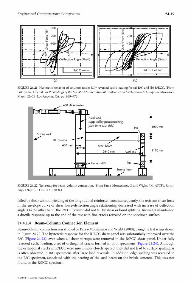
The response of R/ECC and R/C columns under fully reversed cyclic loading was studied by Fukuyamaet al. (2000). These columns were tested under the antisymmetrical moment condition. The axial forceapplied to the column was 20% of the axial compressive strength of the column, calculated without thecontribution of the steel reinforcements. The hysteretic behavior in terms of stability and energy dissi-pation was improved in the R/ECC column over the R/C column in a manner similar to that for flexuraland shear elements (Figure 24.21). Large bond splitting cracks were observed in the R/C column, which
FIGURE 24.19 Hysteretic loops for Ohno shear beams under fully reversed cyclic loading for (a) R/C and (b) R/ECC.(From Fukuyama, H. et al., in Proceedings of the 6th ASCCS International Conference on Steel–Concrete CompositeStructures, March 22–24, Los Angeles, CA, pp. 969–976.)
FIGURE 24.20 Damage pattern in Ohno shear beams: (a) R/C, and (b) R/ECC. (From Fukuyama, H. et al., inProceedings of the 6th ASCCS International Conference on Steel–Concrete Composite Structures, March 22–24, LosAngeles, CA, pp. 969–976.)
(a)
–5 –4 –5 –6 –7 1 2 3 4 5 6
She
ar F
orc
e (
kN)
Deflection Angle (%rad)
R/C Beam
–5 –4 –5 –6 –7 1 2 3 4 5 6
200
150
100
50
–150
–200
She
ar F
orc
e (
kN)
Deflection Angle (%rad)
PVA-ECC Beam
(b)
–100
–50
0
200
150
100
50
–150
–200
–100
–50
(a)
(b)
© 2008 by Taylor & Francis Group, LLC
Engineered Cementitious Composites 24-19
failed by shear without yielding of the longitudinal reinforcements; subsequently, the resistant shear forcein the envelope curve of shear force–deflection angle relationship decreased with increase of deflectionangle. On the other hand, the R/ECC column did not fail by shear or bond splitting. Instead, it maintaineda ductile response up to the end of the test with fine cracks revealed on the specimen surface.
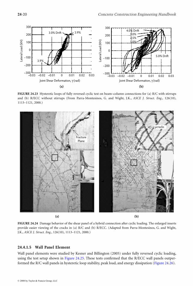
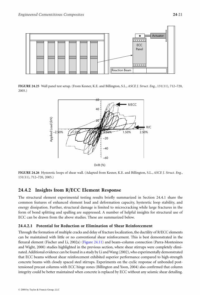
24.4.1.4 Beam–Column Connection Element
Beam–column connection was studied by Parra-Montesinos and Wight (2000), using the test setup shownin Figure 24.22. The hysteretic response for the R/ECC shear panel was substantially improved over theR/C (Figure 24.23), even when all shear stirrups were removed in the R/ECC shear panel. Under fullyreversed cyclic loading, a set of orthogonal cracks formed in both specimens (Figure 24.24). Althoughthe orthogonal cracks in R/ECC were much more closely spaced, they did not lead to surface spalling asis often observed in R/C specimens after large load reversals. In addition, edge spalling was revealed inthe R/C specimen, associated with the bearing of the steel beam on the brittle concrete. This was notfound in the R/ECC specimen.
FIGURE 24.21 Hysteretic behavior of columns under fully reversed cyclic loading for (a) R/C and (b) R/ECC. (FromFukuyama, H. et al., in Proceedings of the 6th ASCCS International Conference on Steel–Concrete Composite Structures,March 22–24, Los Angeles, CA, pp. 969–976.)
FIGURE 24.22 Test setup for beam–column connection. (From Parra-Montesinos, G. and Wight, J.K., ASCE J. Struct.Eng., 126(10), 1113–1121, 2000.)
–6 –4 –2 0 2 4
300
200
100
00
100
200
300
She
ar F
orc
e (
kN)
Deflection Angle (%rad)
R/C Column
–6 –4 –2 0 2 4 6
300
200
100
00
100
200
300
She
ar F
orc
e (
kN)
Deflection Angle (%rad)
R/ECC Column
(a) (b)
6
450 kN Actuator
Strong wall
RC column
400 mm
Axial load
supplied by posttensioning
jacks (one each side)Pin 1070 mm
1170 mm
Steel beam
2640 mm Axial link
Universal Pin Pin
Strong floor
© 2008 by Taylor & Francis Group, LLC
24-20 Concrete Construction Engineering Handbook
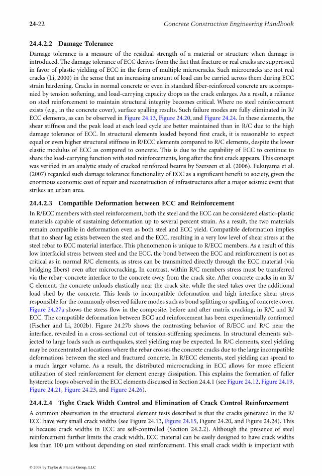
24.4.1.5 Wall Panel Element
Wall panel elements were studied by Kesner and Billington (2005) under fully reversed cyclic loading,using the test setup shown in Figure 24.25. These tests confirmed that the R/ECC wall panels outper-formed the R/C wall panels in hysteretic loop stability, peak load, and energy dissipation (Figure 24.26).
FIGURE 24.23 Hysteretic loops of fully reversed cyclic test on beam–column connections for (a) R/C with stirrupsand (b) R/ECC without stirrups (From Parra-Montesinos, G. and Wight, J.K., ASCE J. Struct. Eng., 126(10),1113–1121, 2000.)
FIGURE 24.24 Damage behavior of the shear panel of a hybrid connection after cyclic loading. The enlarged insertsprovide easier viewing of the cracks in (a) R/C and (b) R/ECC. (Adapted from Parra-Montesinos, G. and Wight,J.K., ASCE J. Struct. Eng., 126(10), 1113–1121, 2000.)
300
200
100
0
–100
–200
–300
Late
ral L
oad
(kN
)
–0.03 –0.02 –0.01 0 0.01 0.02 0.03
3.9%
3.0% Drift 3.9%
Joint Shear Deformation, γ (rad)Joint Shear Deformation, γ (rad)
300
200
100
–100
–200
–300–0.03 –0.02 –0.01 0 0.01 0.02 0.03
0
Late
ral L
oad
(K
N)
1.0%
2.5%3.0%
4.0% Drift
5.0% Drift
(a) (b)
Fracture
Plane
µcracks
(a) (b)
© 2008 by Taylor & Francis Group, LLC
Engineered Cementitious Composites 24-21
24.4.2 Insights from R/ECC Element Response
The structural element experimental testing results briefly summarized in Section 24.4.1 share thecommon features of enhanced element load and deformation capacity, hysteretic loop stability, andenergy dissipation. Further, structural damage is limited to microcracking while large fractures in theform of bond splitting and spalling are suppressed. A number of helpful insights for structural use ofECC can be drawn from the above studies. These are summarized below.
24.4.2.1 Potential for Reduction or Elimination of Shear Reinforcement
Through the formation of multiple cracks and delay of fracture localization, the ductility of R/ECC elementscan be maintained with little or no conventional shear reinforcement. This is best demonstrated in theflexural element (Fischer and Li, 2002a) (Figure 24.11) and beam–column connection (Parra-Montesinosand Wight, 2000) studies highlighted in the previous section, where shear stirrups were completely elimi-nated. Additional evidence can be found in a study by Li and Wang (2002), who experimentally demonstratedthat ECC beams without shear reinforcement exhibited superior performance compared to high-strengthconcrete beams with closely spaced steel stirrups. Experiments on the cyclic response of unbonded post-tensioned precast columns with ECC hinge zones (Billington and Yoon, 2004) also confirmed that columnintegrity could be better maintained when concrete is replaced by ECC without any seismic shear detailing.
FIGURE 24.25 Wall panel test setup. (From Kesner, K.E. and Billington, S.L., ASCE J. Struct. Eng., 131(11), 712–720,2005.)
FIGURE 24.26 Hysteretic loops of shear wall. (Adapted from Kesner, K.E. and Billington, S.L., ASCE J. Struct. Eng.,131(11), 712–720, 2005.)
Reaction Beam
ECC
Panel
Actuator
Ap
plie
d L
oad
(kN
)
–2.50% –1.50% –0.50% 0.50% 1.50% 2.50%
60
40
20
–20
–40
–60
Drift (%)
R/ECC
R/C
© 2008 by Taylor & Francis Group, LLC
24-22 Concrete Construction Engineering Handbook
24.4.2.2 Damage Tolerance
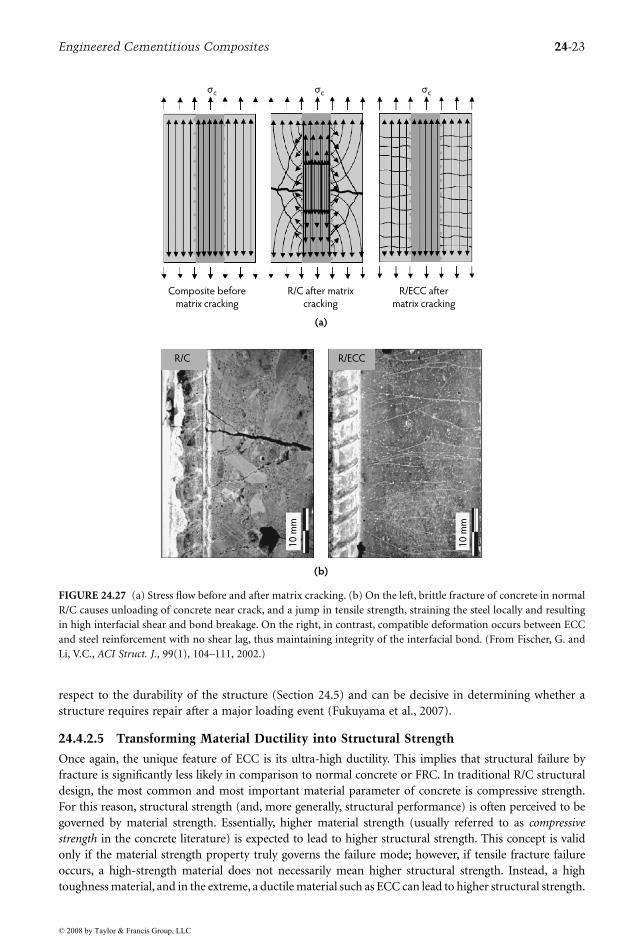
Damage tolerance is a measure of the residual strength of a material or structure when damage isintroduced. The damage tolerance of ECC derives from the fact that fracture or real cracks are suppressedin favor of plastic yielding of ECC in the form of multiple microcracks. Such microcracks are not realcracks (Li, 2000) in the sense that an increasing amount of load can be carried across them during ECCstrain hardening. Cracks in normal concrete or even in standard fiber-reinforced concrete are accompa-nied by tension softening, and load-carrying capacity drops as the crack enlarges. As a result, a relianceon steel reinforcement to maintain structural integrity becomes critical. Where no steel reinforcementexists (e.g., in the concrete cover), surface spalling results. Such failure modes are fully eliminated in R/ECC elements, as can be observed in Figure 24.13, Figure 24.20, and Figure 24.24. In these elements, theshear stiffness and the peak load at each load cycle are better maintained than in R/C due to the highdamage tolerance of ECC. In structural elements loaded beyond first crack, it is reasonable to expectequal or even higher structural stiffness in R/ECC elements compared to R/C elements, despite the lowerelastic modulus of ECC as compared to concrete. This is due to the capability of ECC to continue toshare the load-carrying function with steel reinforcements, long after the first crack appears. This conceptwas verified in an analytic study of cracked reinforced beams by Szerszen et al. (2006). Fukuyama et al.(2007) regarded such damage tolerance functionality of ECC as a significant benefit to society, given theenormous economic cost of repair and reconstruction of infrastructures after a major seismic event thatstrikes an urban area.
24.4.2.3 Compatible Deformation between ECC and Reinforcement
In R/ECC members with steel reinforcement, both the steel and the ECC can be considered elastic–plasticmaterials capable of sustaining deformation up to several percent strain. As a result, the two materialsremain compatible in deformation even as both steel and ECC yield. Compatible deformation impliesthat no shear lag exists between the steel and the ECC, resulting in a very low level of shear stress at thesteel rebar to ECC material interface. This phenomenon is unique to R/ECC members. As a result of thislow interfacial stress between steel and the ECC, the bond between the ECC and reinforcement is not ascritical as in normal R/C elements, as stress can be transmitted directly through the ECC material (viabridging fibers) even after microcracking. In contrast, within R/C members stress must be transferredvia the rebar–concrete interface to the concrete away from the crack site. After concrete cracks in an R/C element, the concrete unloads elastically near the crack site, while the steel takes over the additionalload shed by the concrete. This leads to incompatible deformation and high interface shear stressresponsible for the commonly observed failure modes such as bond splitting or spalling of concrete cover.Figure 24.27a shows the stress flow in the composite, before and after matrix cracking, in R/C and R/ECC. The compatible deformation between ECC and reinforcement has been experimentally confirmed(Fischer and Li, 2002b). Figure 24.27b shows the contrasting behavior of R/ECC and R/C near theinterface, revealed in a cross-sectional cut of tension-stiffening specimens. In structural elements sub-jected to large loads such as earthquakes, steel yielding may be expected. In R/C elements, steel yieldingmay be concentrated at locations where the rebar crosses the concrete cracks due to the large incompatibledeformations between the steel and fractured concrete. In R/ECC elements, steel yielding can spread toa much larger volume. As a result, the distributed microcracking in ECC allows for more efficientutilization of steel reinforcement for element energy dissipation. This explains the formation of fullerhysteretic loops observed in the ECC elements discussed in Section 24.4.1 (see Figure 24.12, Figure 24.19,Figure 24.21, Figure 24.23, and Figure 24.26).
24.4.2.4 Tight Crack Width Control and Elimination of Crack Control Reinforcement
A common observation in the structural element tests described is that the cracks generated in the R/
is because crack widths in ECC are self-controlled (Section 24.2.2). Although the presence of steelreinforcement further limits the crack width, ECC material can be easily designed to have crack widthsless than 100 µm without depending on steel reinforcement. This small crack width is important with
© 2008 by Taylor & Francis Group, LLC
ECC have very small crack widths (see Figure 24.13, Figure 24.15, Figure 24.20, and Figure 24.24). This
Engineered Cementitious Composites 24-23
respect to the durability of the structure (Section 24.5) and can be decisive in determining whether astructure requires repair after a major loading event (Fukuyama et al., 2007).
24.4.2.5 Transforming Material Ductility into Structural Strength
Once again, the unique feature of ECC is its ultra-high ductility. This implies that structural failure byfracture is significantly less likely in comparison to normal concrete or FRC. In traditional R/C structuraldesign, the most common and most important material parameter of concrete is compressive strength.For this reason, structural strength (and, more generally, structural performance) is often perceived to begoverned by material strength. Essentially, higher material strength (usually referred to as compressivestrength in the concrete literature) is expected to lead to higher structural strength. This concept is validonly if the material strength property truly governs the failure mode; however, if tensile fracture failureoccurs, a high-strength material does not necessarily mean higher structural strength. Instead, a hightoughness material, and in the extreme, a ductile material such as ECC can lead to higher structural strength.
FIGURE 24.27 (a) Stress flow before and after matrix cracking. (b) On the left, brittle fracture of concrete in normalR/C causes unloading of concrete near crack, and a jump in tensile strength, straining the steel locally and resultingin high interfacial shear and bond breakage. On the right, in contrast, compatible deformation occurs between ECCand steel reinforcement with no shear lag, thus maintaining integrity of the interfacial bond. (From Fischer, G. andLi, V.C., ACI Struct. J., 99(1), 104–111, 2002.)
R/C after matrix
cracking
Composite before
matrix cracking
R/ECC after
matrix cracking
(a)
(b)
R/C R/ECC
10
mm
10
mm
σc σc σc
© 2008 by Taylor & Francis Group, LLC
24-24 Concrete Construction Engineering Handbook
A number of experimental observations (Fukuyama et al., 2000; Kanda et al. 1998; Kesner andBillington, 2005; Lim and Li, 1997) provide support for the above reasoning. For example, the shearbeam elements tested by Fukuyama et al. (2000) (Figure 24.18) have compressive strengths of 58.3 MPaand 52.5 MPa for concrete and ECC, respectively; however, the structural load capacity was 120 kN vs.140 kN for the R/C and R/ECC elements, respectively (Figure 24.19). As another example, the precastin-fill wall panels (Figure 24.25) tested by Kesner and Billington (2005) for seismic retrofitting of buildingsrevealed that a panel with a concrete of compressive strength of 50 MPa attained a structural (shear)strength of 38 kN, while a similar panel made with ECC material of lower compressive strength (41 MPa)achieved a much higher structural strength of 56 kN (Figure 24.26). The over 35% structural strengthgain in the R/ECC panel can be attributed to the material ductility of the ECC which prolonged integrityof the panel to a larger drift level. Similarly, detailed numerical analysis (Kabele, 2001) of a wall panelmade with ECC demonstrated a structural strength three times that of the panel made with FRC, despitethe fact that both materials had the same tensile and compressive strengths.
24.5 Durability of ECC and ECC Structural Elements
24.5.1 Material and Element Durability
As a new construction material, it is not enough to have excellent mechanical performance comparedwith conventional concrete or FRC. It is also important to verify the durability of the ECC material itselfin various environments typical of where such materials are expected to be used. In addition, the influenceof this material on structural durability performance of R/ECC must also be confirmed. In most cases,laboratory studies are performed under accelerated conditions; however, long-term performance in thefield is most valuable even though it is difficult to obtain, especially for a relatively new material.
Because the greatest value of ECC lies in its superior tensile ductility, this material will likely be usedin structures that impose large deformations on the material. This implies that the structure must remainserviceable even if the material undergoes tensile strain hardening accompanied by multiple microcrack-ing. For this reason, the examination of ECC material durability should be carried out in the deformedcracked state; that is, the ECC specimen should undergo preloading to varying strain levels to deliberatelycreate microcrack damage, prior to accelerated exposure tests. Experimental data thus determined frompreloaded specimens may be considered as material durability properties under combined mechanicaland environmental load. It should be noted, however, that most of these experiments were undertakenwith cracked specimens in the unloaded state for experimental testing convenience. On unloading, crackwidths in ECC tend to reduce by 10 to 20% from the loaded state. This reduced crack width is used inall experimental data reported. This difference from field conditions where cracks are typically underload is not expected to have a significant impact on the measured durability of ECC material or R/ECCstructures but should be verified in future studies.
As will become clear in the following subsections, the durability of ECC and especially of ECCstructures can be sensitive to the width of the microcracks. Microcrack widths are therefore designed tobe small, typically less than 100 µm for ECC, and potentially much lower. These cracks remain smallunder fatigue loading, as indicated in Section 24.4.1.1; however, a recent study by Boshoff and van Zijl(2007) indicates that crack width may open wider under sustained loading due to creep mechanisms.Care must be taken for the long-term durability of a structure under combined conditions of sustainedloading, deformation to the strain-hardening stage, and exposure to an aggressive environment.
In Section 24.5.2, current knowledge of ECC durability under various environments is summarized.In Section 24.5.3, the durability of R/ECC under chloride exposure is presented. This discussion isfollowed in Section 24.5.4 by highlights of limited long-term performance data on ECC materials alreadyin structures exposed to the natural environment and (in one case) in combination with mechanicalloads. Additional studies of ECC under various environmental or loading conditions can be found inthe references in Table 24.5. Most of the durability studies covered here are for ECC reinforced with PVAfibers. The durability of PVA fiber itself has been summarized by Horikoshi et al. (2006).
© 2008 by Taylor & Francis Group, LLC
Engineered Cementitious Composites 24-25
24.5.2 ECC Durability under Various EnvironmentsIn this section, current knowledge on long-term strain capacity, as well as ECC exposed to variouscommonly encountered environments is summarized. These environments include freeze–thaw cycles,hot–wet cycles, chloride immersion, deicing salt exposure, and alkali–silica reaction (ASR) resistance.
24.5.2.1 Long-Term Tensile Strain Capacity
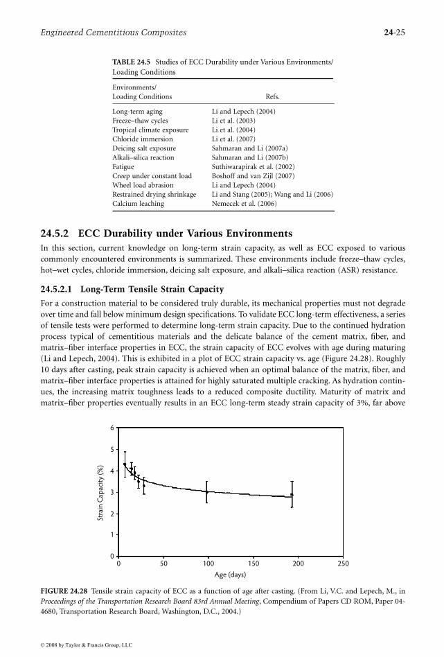
For a construction material to be considered truly durable, its mechanical properties must not degradeover time and fall below minimum design specifications. To validate ECC long-term effectiveness, a seriesof tensile tests were performed to determine long-term strain capacity. Due to the continued hydrationprocess typical of cementitious materials and the delicate balance of the cement matrix, fiber, andmatrix–fiber interface properties in ECC, the strain capacity of ECC evolves with age during maturing(Li and Lepech, 2004). This is exhibited in a plot of ECC strain capacity vs. age (Figure 24.28). Roughly10 days after casting, peak strain capacity is achieved when an optimal balance of the matrix, fiber, andmatrix–fiber interface properties is attained for highly saturated multiple cracking. As hydration contin-ues, the increasing matrix toughness leads to a reduced composite ductility. Maturity of matrix andmatrix–fiber properties eventually results in an ECC long-term steady strain capacity of 3%, far above
TABLE 24.5 Studies of ECC Durability under Various Environments/Loading Conditions
Environments/Loading Conditions Refs.
Long-term aging Li and Lepech (2004)Freeze–thaw cycles Li et al. (2003)Tropical climate exposure Li et al. (2004)Chloride immersion Li et al. (2007)Deicing salt exposure Sahmaran and Li (2007a)Alkali–silica reaction Sahmaran and Li (2007b)Fatigue Suthiwarapirak et al. (2002)Creep under constant load Boshoff and van Zijl (2007)Wheel load abrasion Li and Lepech (2004)Restrained drying shrinkage Li and Stang (2005); Wang and Li (2006)Calcium leaching Nemecek et al. (2006)
FIGURE 24.28 Tensile strain capacity of ECC as a function of age after casting. (From Li, V.C. and Lepech, M., inProceedings of the Transportation Research Board 83rd Annual Meeting, Compendium of Papers CD ROM, Paper 04-4680, Transportation Research Board, Washington, D.C., 2004.)
0 50 100 150 200 250
Age (days)
6
5
4
3
2
1
0
Stra
in C
apac
ity
(%)
© 2008 by Taylor & Francis Group, LLC
24-26 Concrete Construction Engineering Handbook
the deformation demand imposed by many structural applications but significantly less than the 5%capacity seen at early age. Although long-term tests have only been carried out to 180 days, the long-term strain capacity is expected to remain at approximately 3%. The strain capacity–age curve can beseen as analogous to the compressive strength development curve in normal concrete; however, becauseit is not monotonically rising, the long-term value should be used for design purposes. For simplicity,90% of the 28-day strain capacity value that approaches asymptotically to the long-term behavior maybe adopted as the design strain capacity. This simplifies the design process, as the same 28-day value isused for compressive strength specification.
24.5.2.2 Freeze–Thaw Durability
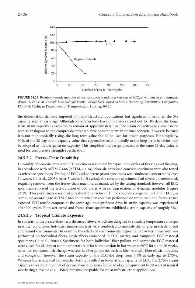
Durability of non-air-entrained ECC specimens was tested by exposure to cycles of freezing and thawing,in accordance with ASTM C 666 (ASTM, 2003a). Non-air-entrained concrete specimens were also testedas reference specimens. Testing of ECC and concrete prism specimens was conducted concurrently over14 weeks (Li et al., 2003). After 5 weeks (110 cycles), the concrete specimens had severely deteriorated,requiring removal from the freeze–thaw machine, as mandated by the testing standard; however, all ECCspecimens survived the test duration of 300 cycles with no degradation of dynamic modulus (Figure24.29). This performance resulted in a durability factor of 10 for concrete compared to 100 for ECC, ascomputed according to ASTM C 666. In uniaxial tension tests performed on wet-cured- and freeze–thaw-exposed ECC tensile coupons at the same age, no significant drop in strain capacity was experiencedafter 300 cycles. Both wet-cured and freeze–thaw specimens exhibited a strain capacity of roughly 3%.
24.5.2.3 Tropical Climate Exposure
In contrast to the freeze–thaw tests discussed above, which are designed to simulate temperature changesin winter conditions, hot-water immersion tests were conducted to simulate the long-term effects of hotand humid environments. To examine the effects of environmental exposure, hot-water immersion wasperformed on individual fibers, single fibers embedded in ECC matrix, and composite ECC materialspecimens (Li et al., 2004a). Specimens for both individual fiber pullout and composite ECC materialwere cured for 28 days at room temperature prior to immersion in hot water at 60°C for up to 26 weeks.After this exposure, little change was seen in fiber properties such as fiber strength, fiber elastic modulus,and elongation; however, the strain capacity of the ECC did drop from 4.5% at early age to 2.75%.Whereas the accelerated hot weather testing resulted in lower strain capacity of ECC, the 2.75% straincapacity (over 250 times that of normal concrete) seen after 26 weeks and equivalent to 70 years of naturalweathering (Proctor et al., 1982) remains acceptable for most infrastructure applications.
FIGURE 24.29 Relative dynamic modulus of normal concrete and three versions of ECC, all without air entrainment.(From Li, V.C. et al., Durable Link Slabs for Jointless Bridge Decks Based on Strain-Hardening Cementitious Composites,RC-1438, Michigan Department of Transportation, Lansing, 2003.)
140
120
100
80
60
40
20
0 50 100 150 200 250 300 3500
Number of Freeze–Thaw Cycles
Re
lati
ve D
ynam
ic M
od
ulu
s (%
)
Regular Concrete
ECC
© 2008 by Taylor & Francis Group, LLC
Engineered Cementitious Composites 24-27
24.5.2.4 Chloride Immersion
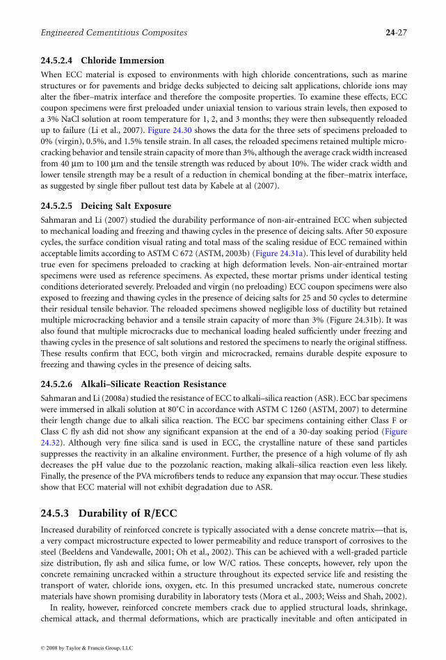
When ECC material is exposed to environments with high chloride concentrations, such as marinestructures or for pavements and bridge decks subjected to deicing salt applications, chloride ions mayalter the fiber–matrix interface and therefore the composite properties. To examine these effects, ECCcoupon specimens were first preloaded under uniaxial tension to various strain levels, then exposed toa 3% NaCl solution at room temperature for 1, 2, and 3 months; they were then subsequently reloadedup to failure (Li et al., 2007). Figure 24.30 shows the data for the three sets of specimens preloaded to0% (virgin), 0.5%, and 1.5% tensile strain. In all cases, the reloaded specimens retained multiple micro-cracking behavior and tensile strain capacity of more than 3%, although the average crack width increasedfrom 40 µm to 100 µm and the tensile strength was reduced by about 10%. The wider crack width andlower tensile strength may be a result of a reduction in chemical bonding at the fiber–matrix interface,as suggested by single fiber pullout test data by Kabele at al (2007).
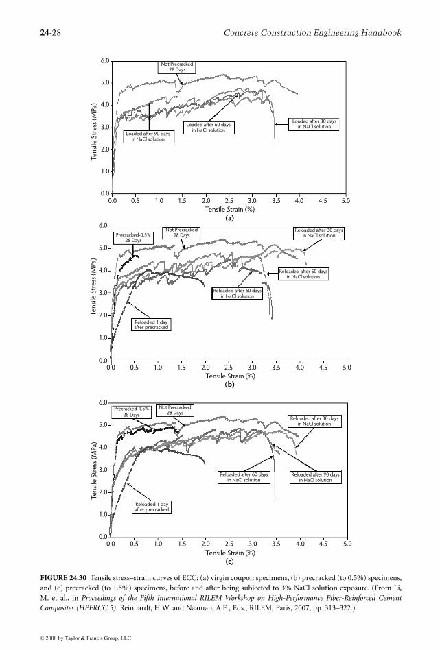
24.5.2.5 Deicing Salt Exposure
Sahmaran and Li (2007) studied the durability performance of non-air-entrained ECC when subjectedto mechanical loading and freezing and thawing cycles in the presence of deicing salts. After 50 exposurecycles, the surface condition visual rating and total mass of the scaling residue of ECC remained withinacceptable limits according to ASTM C 672 (ASTM, 2003b) (Figure 24.31a). This level of durability heldtrue even for specimens preloaded to cracking at high deformation levels. Non-air-entrained mortarspecimens were used as reference specimens. As expected, these mortar prisms under identical testingconditions deteriorated severely. Preloaded and virgin (no preloading) ECC coupon specimens were alsoexposed to freezing and thawing cycles in the presence of deicing salts for 25 and 50 cycles to determinetheir residual tensile behavior. The reloaded specimens showed negligible loss of ductility but retainedmultiple microcracking behavior and a tensile strain capacity of more than 3% (Figure 24.31b). It wasalso found that multiple microcracks due to mechanical loading healed sufficiently under freezing andthawing cycles in the presence of salt solutions and restored the specimens to nearly the original stiffness.These results confirm that ECC, both virgin and microcracked, remains durable despite exposure tofreezing and thawing cycles in the presence of deicing salts.
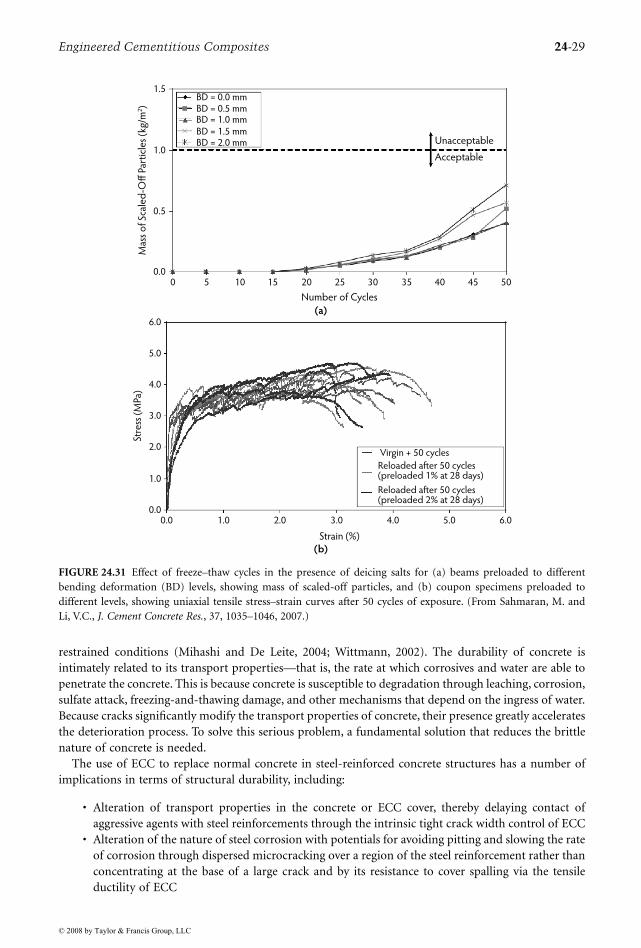
24.5.2.6 Alkali–Silicate Reaction Resistance
Sahmaran and Li (2008a) studied the resistance of ECC to alkali–silica reaction (ASR). ECC bar specimenswere immersed in alkali solution at 80˚C in accordance with ASTM C 1260 (ASTM, 2007) to determinetheir length change due to alkali silica reaction. The ECC bar specimens containing either Class F orClass C fly ash did not show any significant expansion at the end of a 30-day soaking period (Figure24.32). Although very fine silica sand is used in ECC, the crystalline nature of these sand particlessuppresses the reactivity in an alkaline environment. Further, the presence of a high volume of fly ashdecreases the pH value due to the pozzolanic reaction, making alkali–silica reaction even less likely.Finally, the presence of the PVA microfibers tends to reduce any expansion that may occur. These studiesshow that ECC material will not exhibit degradation due to ASR.
24.5.3 Durability of R/ECC
Increased durability of reinforced concrete is typically associated with a dense concrete matrix—that is,a very compact microstructure expected to lower permeability and reduce transport of corrosives to thesteel (Beeldens and Vandewalle, 2001; Oh et al., 2002). This can be achieved with a well-graded particlesize distribution, fly ash and silica fume, or low W/C ratios. These concepts, however, rely upon theconcrete remaining uncracked within a structure throughout its expected service life and resisting thetransport of water, chloride ions, oxygen, etc. In this presumed uncracked state, numerous concretematerials have shown promising durability in laboratory tests (Mora et al., 2003; Weiss and Shah, 2002).
In reality, however, reinforced concrete members crack due to applied structural loads, shrinkage,chemical attack, and thermal deformations, which are practically inevitable and often anticipated in
© 2008 by Taylor & Francis Group, LLC
24-28 Concrete Construction Engineering Handbook
FIGURE 24.30 Tensile stress–strain curves of ECC: (a) virgin coupon specimens, (b) precracked (to 0.5%) specimens,and (c) precracked (to 1.5%) specimens, before and after being subjected to 3% NaCl solution exposure. (From Li,M. et al., in Proceedings of the Fifth International RILEM Workshop on High-Performance Fiber-Reinforced CementComposites (HPFRCC 5), Reinhardt, H.W. and Naaman, A.E., Eds., RILEM, Paris, 2007, pp. 313–322.)
Not Precracked28 Days
Loaded after 90 daysin NaCl solution
Precracked-0.5%28 Days
Reloaded 1 dayafter precracked
Not Precracked28 Days
Not Precracked28 Days
Loaded after 60 daysin NaCl solution
Loaded after 30 daysin NaCl solution
Reloaded after 60 daysin NaCl solution
Reloaded after 50 daysin NaCl solution
Reloaded after 30 daysin NaCl solution
Reloaded after 30 daysin NaCl solution
Reloaded after 90 daysin NaCl solution
Reloaded after 60 daysin NaCl solution
Reloaded 1 dayafter precracked
6.0
5.0
4.0
3.0
2.0
1.0
0.0
6.0
5.0
4.0
3.0
2.0
1.0
0.0
6.0
5.0
4.0
3.0
2.0
1.0
0.00.0 0.5 1.0 1.5 2.0 2.5 3.0 3.5 4.0 4.5 5.0
0.0 0.5 1.0 1.5 2.0 2.5 3.0 3.5 4.0 4.5 5.0
0.0 0.5 1.0 1.5 2.0 2.5 3.0 3.5 4.0 4.5 5.0
Tensile Strain (%)
Tensile Strain (%)
Tensile Strain (%)
Te
nsi
le S
tre
ss (
MPa
)T
en
sile
Str
ess
(M
Pa)
Te
nsi
le S
tre
ss (
MPa
)
Precracked-1.5%
28 Days
(a)
(b)
(c)
© 2008 by Taylor & Francis Group, LLC
Engineered Cementitious Composites 24-29
restrained conditions (Mihashi and De Leite, 2004; Wittmann, 2002). The durability of concrete isintimately related to its transport properties—that is, the rate at which corrosives and water are able topenetrate the concrete. This is because concrete is susceptible to degradation through leaching, corrosion,sulfate attack, freezing-and-thawing damage, and other mechanisms that depend on the ingress of water.Because cracks significantly modify the transport properties of concrete, their presence greatly acceleratesthe deterioration process. To solve this serious problem, a fundamental solution that reduces the brittlenature of concrete is needed.
The use of ECC to replace normal concrete in steel-reinforced concrete structures has a number ofimplications in terms of structural durability, including:
• Alteration of transport properties in the concrete or ECC cover, thereby delaying contact ofaggressive agents with steel reinforcements through the intrinsic tight crack width control of ECC
• Alteration of the nature of steel corrosion with potentials for avoiding pitting and slowing the rateof corrosion through dispersed microcracking over a region of the steel reinforcement rather thanconcentrating at the base of a large crack and by its resistance to cover spalling via the tensileductility of ECC
FIGURE 24.31 Effect of freeze–thaw cycles in the presence of deicing salts for (a) beams preloaded to differentbending deformation (BD) levels, showing mass of scaled-off particles, and (b) coupon specimens preloaded todifferent levels, showing uniaxial tensile stress–strain curves after 50 cycles of exposure. (From Sahmaran, M. andLi, V.C., J. Cement Concrete Res., 37, 1035–1046, 2007.)
BD = 0.0 mmBD = 0.5 mmBD = 1.0 mmBD = 1.5 mmBD = 2.0 mm
1.5
1.0
0.5
0.00 5 10 15 20 25 30 35 40 45 50
Number of Cycles
Mas
s o
f Sc
ale
d-O
ff P
arti
cle
s (k
g/m
2)
6.0
5.0
4.0
3.0
2.0
1.0
0.0
Stre
ss (
MPa
)
0.0 1.0 2.0 3.0 4.0 5.0 6.0
Strain (%)
Virgin + 50 cycles
Reloaded after 50 cycles(preloaded 1% at 28 days)
Reloaded after 50 cycles(preloaded 2% at 28 days)
Unacceptable
Acceptable
(a)
(b)
© 2008 by Taylor & Francis Group, LLC
24-30 Concrete Construction Engineering Handbook
These two alterations lead to expected improvements in structural durability due to a delay in theinitiation phase of steel corrosion, and they dramatically slow the steel corrosion propagation phase. Anumber of experimental research efforts have been conducted that focus on the transport properties ofECC, especially when it is already in the strain-hardening stage with the presence of multiple microcracks,as well as on the behavior of steel-reinforced ECC elements in accelerated testing environments. Majorfindings of these two aspects are summarized in the following subsections. Recommendations for thedesign of R/ECC structures to protect against carbonation and chloride-ion-induced steel corrosion canbe found in Rokugo et al. (2007).
24.5.3.1 Transport Properties of ECC
The most important transport properties of ECC include:
FIGURE 24.32 Length change of ECC mix with (a) Class F fly ash and (b) Class C fly ash subjected to alkali–silicareaction tests. (From Sahmaran, M. and Li, V.C., J. Cement Concrete Composites, 2008.)
0.25
0.20
0.15
0.10
0.05
0.00
–0.05
0.25
0.20
0.15
0.10
0.05
0.00
–0.05
Time (days)
Exp
ansi
on
(%
)Ex
pan
sio
n (
%)
Harmful
Repetition
Harmless
Harmful
Repetition
Harmless
5 10 15 20 25 30
50
0
10 15 20 25 30
Time (days)
(a)
(b)
ECC (FA/C = 1.2)
ECC (FA/C = 2.2)
ECC (FA/C = 1.2)
ECC (FA/C = 2.2)
© 2008 by Taylor & Francis Group, LLC
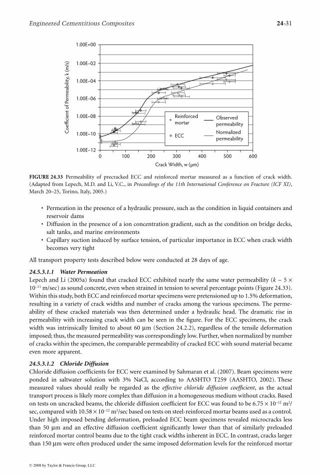
Engineered Cementitious Composites 24-31
• Permeation in the presence of a hydraulic pressure, such as the condition in liquid containers andreservoir dams
• Diffusion in the presence of a ion concentration gradient, such as the condition on bridge decks,salt tanks, and marine environments
• Capillary suction induced by surface tension, of particular importance in ECC when crack widthbecomes very tight
All transport property tests described below were conducted at 28 days of age.
24.5.3.1.1 Water PermeationLepech and Li (2005a) found that cracked ECC exhibited nearly the same water permeability (k ~ 5 ×10–11 m/sec) as sound concrete, even when strained in tension to several percentage points (Figure 24.33).Within this study, both ECC and reinforced mortar specimens were pretensioned up to 1.5% deformation,resulting in a variety of crack widths and number of cracks among the various specimens. The perme-ability of these cracked materials was then determined under a hydraulic head. The dramatic rise inpermeability with increasing crack width can be seen in the figure. For the ECC specimens, the crackwidth was intrinsically limited to about 60 µm (Section 24.2.2), regardless of the tensile deformationimposed; thus, the measured permeability was correspondingly low. Further, when normalized by numberof cracks within the specimen, the comparable permeability of cracked ECC with sound material becameeven more apparent.
24.5.3.1.2 Chloride DiffusionChloride diffusion coefficients for ECC were examined by Sahmaran et al. (2007). Beam specimens wereponded in saltwater solution with 3% NaCl, according to AASHTO T259 (AASHTO, 2002). Thesemeasured values should really be regarded as the effective chloride diffusion coefficient, as the actualtransport process is likely more complex than diffusion in a homogeneous medium without cracks. Basedon tests on uncracked beams, the chloride diffusion coefficient for ECC was found to be 6.75 × 10⁻¹² m2/sec, compared with 10.58 × 10⁻¹² m2/sec based on tests on steel-reinforced mortar beams used as a control.Under high imposed bending deformation, preloaded ECC beam specimens revealed microcracks lessthan 50 µm and an effective diffusion coefficient significantly lower than that of similarly preloadedreinforced mortar control beams due to the tight crack widths inherent in ECC. In contrast, cracks largerthan 150 µm were often produced under the same imposed deformation levels for the reinforced mortar
FIGURE 24.33 Permeability of precracked ECC and reinforced mortar measured as a function of crack width.(Adapted from Lepech, M.D. and Li, V.C., in Proceedings of the 11th International Conference on Fracture (ICF XI),March 20–25, Torino, Italy, 2005.)
0 100 200 300 400 500 600
Crack Width, w (µm)
1.00E+00
1.00E–02
1.00E–04
1.00E–06
1.00E–08
1.00E–10
1.00E–12
Co
effi
cie
nt
of
Perm
eab
ility
, k (
m/s
)
Observed
permeability
Normalized
permeabilityECC
Reinforced
mortar
© 2008 by Taylor & Francis Group, LLC
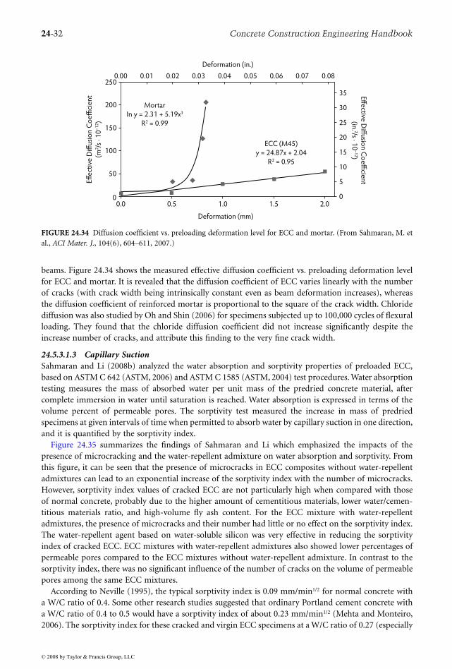
24-32 Concrete Construction Engineering Handbook
beams. Figure 24.34 shows the measured effective diffusion coefficient vs. preloading deformation levelfor ECC and mortar. It is revealed that the diffusion coefficient of ECC varies linearly with the numberof cracks (with crack width being intrinsically constant even as beam deformation increases), whereasthe diffusion coefficient of reinforced mortar is proportional to the square of the crack width. Chloridediffusion was also studied by Oh and Shin (2006) for specimens subjected up to 100,000 cycles of flexuralloading. They found that the chloride diffusion coefficient did not increase significantly despite theincrease number of cracks, and attribute this finding to the very fine crack width.
24.5.3.1.3 Capillary SuctionSahmaran and Li (2008b) analyzed the water absorption and sorptivity properties of preloaded ECC,based on ASTM C 642 (ASTM, 2006) and ASTM C 1585 (ASTM, 2004) test procedures. Water absorptiontesting measures the mass of absorbed water per unit mass of the predried concrete material, aftercomplete immersion in water until saturation is reached. Water absorption is expressed in terms of thevolume percent of permeable pores. The sorptivity test measured the increase in mass of predriedspecimens at given intervals of time when permitted to absorb water by capillary suction in one direction,and it is quantified by the sorptivity index.
Figure 24.35 summarizes the findings of Sahmaran and Li which emphasized the impacts of thepresence of microcracking and the water-repellent admixture on water absorption and sorptivity. Fromthis figure, it can be seen that the presence of microcracks in ECC composites without water-repellentadmixtures can lead to an exponential increase of the sorptivity index with the number of microcracks.However, sorptivity index values of cracked ECC are not particularly high when compared with thoseof normal concrete, probably due to the higher amount of cementitious materials, lower water/cemen-titious materials ratio, and high-volume fly ash content. For the ECC mixture with water-repellentadmixtures, the presence of microcracks and their number had little or no effect on the sorptivity index.The water-repellent agent based on water-soluble silicon was very effective in reducing the sorptivityindex of cracked ECC. ECC mixtures with water-repellent admixtures also showed lower percentages ofpermeable pores compared to the ECC mixtures without water-repellent admixture. In contrast to thesorptivity index, there was no significant influence of the number of cracks on the volume of permeablepores among the same ECC mixtures.
According to Neville (1995), the typical sorptivity index is 0.09 mm/min1/2 for normal concrete witha W/C ratio of 0.4. Some other research studies suggested that ordinary Portland cement concrete witha W/C ratio of 0.4 to 0.5 would have a sorptivity index of about 0.23 mm/min1/2 (Mehta and Monteiro,2006). The sorptivity index for these cracked and virgin ECC specimens at a W/C ratio of 0.27 (especially
FIGURE 24.34 Diffusion coefficient vs. preloading deformation level for ECC and mortar. (From Sahmaran, M. etal., ACI Mater. J., 104(6), 604–611, 2007.)
250
35
30
25
20
15
10
5
0
200
150
100
50
00.0 0.5 1.0 1.5 2.0
Deformation (mm)
Effe
ctiv
e D
iffu
sio
n C
oe
ffici
en
t
(m2/s
· 1
0–
12)
Effe
ctive D
iffu
sion
Co
effi
cien
t
(in. 2/s · 1
0–
12)
0.00 0.01 0.02 0.03 0.04 0.05 0.06 0.07 0.08
Deformation (in.)
ECC (M45)
y = 24.87x + 2.04
R2 = 0.95
Mortar
In y = 2.31 + 5.19x3
R2 = 0.99
© 2008 by Taylor & Francis Group, LLC
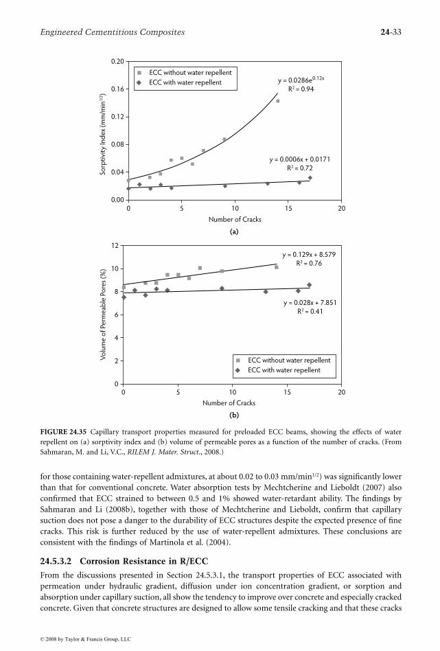
Engineered Cementitious Composites 24-33
for those containing water-repellent admixtures, at about 0.02 to 0.03 mm/min1/2) was significantly lowerthan that for conventional concrete. Water absorption tests by Mechtcherine and Lieboldt (2007) alsoconfirmed that ECC strained to between 0.5 and 1% showed water-retardant ability. The findings bySahmaran and Li (2008b), together with those of Mechtcherine and Lieboldt, confirm that capillarysuction does not pose a danger to the durability of ECC structures despite the expected presence of finecracks. This risk is further reduced by the use of water-repellent admixtures. These conclusions areconsistent with the findings of Martinola et al. (2004).
24.5.3.2 Corrosion Resistance in R/ECC
From the discussions presented in Section 24.5.3.1, the transport properties of ECC associated withpermeation under hydraulic gradient, diffusion under ion concentration gradient, or sorption andabsorption under capillary suction, all show the tendency to improve over concrete and especially crackedconcrete. Given that concrete structures are designed to allow some tensile cracking and that these cracks
FIGURE 24.35 Capillary transport properties measured for preloaded ECC beams, showing the effects of waterrepellent on (a) sorptivity index and (b) volume of permeable pores as a function of the number of cracks. (FromSahmaran, M. and Li, V.C., RILEM J. Mater. Struct., 2008.)
0.20
0.16
0.12
0.08
0.04
0.000 5 10 15 20
Number of Cracks
Sorp
tivi
ty In
de
x (m
m/m
in1
/2)
y = 0.0006x + 0.0171
R2 = 0.72
y = 0.0286e0.12x
R2 = 0.94
ECC without water repellent
ECC with water repellent
12
0
2
4
6
8
10
0 5 10 15 20
Number of Cracks
Vo
lum
e o
f Pe
rme
able
Po
res
(%)
y = 0.028x + 7.851
R2 = 0.41
y = 0.129x + 8.579
R2 = 0.76
ECC without water repellent
ECC with water repellent
(a)
(b)
© 2008 by Taylor & Francis Group, LLC
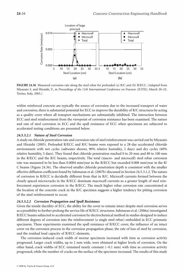
24-34 Concrete Construction Engineering Handbook
within reinforced concrete are typically the source of corrosion due to the increased transport of waterand corrosives, there is substantial potential for ECC to improve the durability of R/C structures by actingas a quality cover where all transport mechanisms are substantially inhibited. The interaction betweenECC and steel reinforcement from the viewpoint of corrosion resistance has been examined. The natureand rate of steel corrosion in ECC and the spall resistance of ECC when specimens are subjected toaccelerated testing conditions are presented below.
24.5.3.2.1 Nature of Steel CorrosionA study on chloride penetration rate and corrosion rate of steel reinforcement was carried out by Miyazatoand Hiraishi (2005). Preloaded R/ECC and R/C beams were exposed to a 28-day accelerated chlorideenvironment with wet cycles (saltwater shower, 90% relative humidity, 2 days) and dry cycles (60%relative humidity, 5 days). They found that chloride penetration reached 0 to 20 mm and 80 to 100 mmin the R/ECC and the R/C beams, respectively. The total (macro- and microcell) steel rebar corrosionrate was measured to be less than 0.0004 mm/year in the R/ECC but exceeded 0.008 mm/year in the R/C beams (Figure 24.36). The observed smaller chloride penetration depth is consistent with the smallereffective diffusion coefficient found by Sahmaran et al. (2007b) discussed in Section 24.5.3.1.2. The natureof corrosion in R/ECC is decidedly different from that in R/C. Microcell currents formed between theclosely spaced microcracks in the R/ECC dominate macrocell currents so a greater length of steel rein-forcement experiences corrosion in the R/ECC. The much higher rebar corrosion rate concentrated atthe location of the concrete crack in the R/C specimen suggests a higher tendency for pitting corrosionof the steel reinforcement to occur.
24.5.3.2.2 Corrosion Propagation and Spall ResistanceGiven the tensile ductility of ECC, the ability for the cover to remain intact despite steel corrosion servesas a possibility to further prolong the service life of R/ECC structures. Sahmaran et al. (2006a) investigatedR/ECC beams subjected to accelerated corrosion by electrochemical method in studies designed to inducedifferent degrees of corrosion into the reinforcement (a single steel rebar) embedded in ECC prismaticspecimens. These experiments examined the spall resistance of R/ECC cover, the influence of an intactcover on the corrosion process in the corrosion propagation phase, the rate of loss of steel by corrosion,and the residual load capacity of R/ECC elements.
The corrosion-induced crack width of mortar specimens increased with time as corrosion activityprogressed. Larger crack widths, up to 2 mm wide, were obtained at higher levels of corrosion. On theother hand, crack widths of ECC remained nearly constant (~0.1 mm) with time as corrosion activityprogressed, while the number of cracks on the surface of the specimen increased. The results of this study
FIGURE 24.36 Measured corrosion rate along the steel rebar for preloaded (a) R/C and (b) R/ECC. (Adapted fromMiyazato S. and Hiraishi, Y., in Proceedings of the 11th International Conference on Fracture (ICFXI), March 20–25,Torino, Italy, 2005.)
5 10 15 20 25 30 35 5 10 15 20 25 30 35
Steel Location (cm) Steel Location (cm)
0.010
0.005
0.000
Co
rro
sio
n R
ate
(m
m/y
ear
)
Location of large
precrack
(a)
Macrocell
MicrocellTotal
Macrocell
MicrocellTotal
(b)
© 2008 by Taylor & Francis Group, LLC
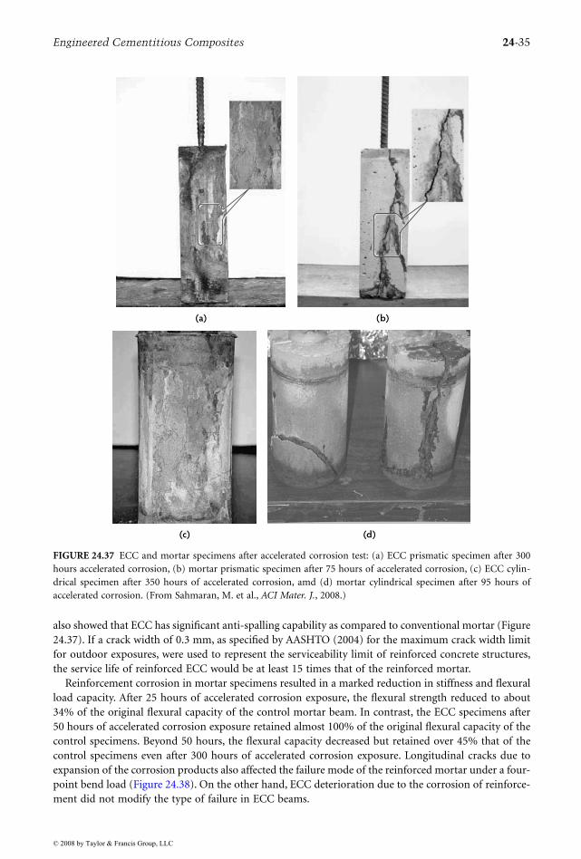
Engineered Cementitious Composites 24-35
also showed that ECC has significant anti-spalling capability as compared to conventional mortar (Figure24.37). If a crack width of 0.3 mm, as specified by AASHTO (2004) for the maximum crack width limitfor outdoor exposures, were used to represent the serviceability limit of reinforced concrete structures,the service life of reinforced ECC would be at least 15 times that of the reinforced mortar.
Reinforcement corrosion in mortar specimens resulted in a marked reduction in stiffness and flexuralload capacity. After 25 hours of accelerated corrosion exposure, the flexural strength reduced to about34% of the original flexural capacity of the control mortar beam. In contrast, the ECC specimens after50 hours of accelerated corrosion exposure retained almost 100% of the original flexural capacity of thecontrol specimens. Beyond 50 hours, the flexural capacity decreased but retained over 45% that of thecontrol specimens even after 300 hours of accelerated corrosion exposure. Longitudinal cracks due toexpansion of the corrosion products also affected the failure mode of the reinforced mortar under a four-point bend load (Figure 24.38). On the other hand, ECC deterioration due to the corrosion of reinforce-ment did not modify the type of failure in ECC beams.
FIGURE 24.37 ECC and mortar specimens after accelerated corrosion test: (a) ECC prismatic specimen after 300hours accelerated corrosion, (b) mortar prismatic specimen after 75 hours of accelerated corrosion, (c) ECC cylin-drical specimen after 350 hours of accelerated corrosion, amd (d) mortar cylindrical specimen after 95 hours ofaccelerated corrosion. (From Sahmaran, M. et al., ACI Mater. J., 2008.)
(a) (b)
(c) (d)
© 2008 by Taylor & Francis Group, LLC
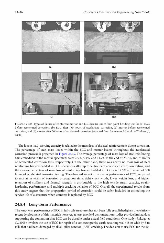
24-36 Concrete Construction Engineering Handbook
The loss in load-carrying capacity is related to the mass loss of the steel reinforcement due to corrosion.The percentage of steel mass losses within the ECC and mortar beams throughout the acceleratedcorrosion process is presented in Figure 24.39. The average percentage of mass loss of steel reinforcingbars embedded in the mortar specimens were 2.5%, 5.3%, and 11.7% at the end of 25, 50, and 75 hoursof accelerated corrosion tests, respectively. On the other hand, there was nearly no mass loss of steelreinforcing bars embedded in ECC specimens after up to 50 hours of accelerated corrosion testing, andthe average percentage of mass loss of reinforcing bars embedded in ECC was 17.5% at the end of 300hours of accelerated corrosion testing. The observed superior corrosion performance of ECC comparedto mortar in terms of corrosion propagation time, tight crack width, lower weight loss, and higherretention of stiffness and flexural strength is attributable to the high tensile strain capacity, strain-hardening performance, and multiple cracking behavior of ECC. Overall, the experimental results fromthis study suggest that the propagation period of corrosion could be safely included in estimating theservice life of a structure when concrete is replaced by ECC.
24.5.4 Long-Term Performance
The long-term performance of ECC in full-scale structures has not been fully established given the relativelyrecent development of this material; however, at least two field demonstration studies provide limited datasupporting the contention that ECC can be durable under actual field conditions. One study (Rokugo etal., 2005) involves the use of ECC for repair of a concrete gravity earth-retaining wall (18 m wide by 5 mtall) that had been damaged by alkali–silica reaction (ASR) cracking. The decision to use ECC for the 50-
FIGURE 24.38 Types of failure of reinforced mortar and ECC beams under four-point bending test for (a) ECCbefore accelerated corrosion, (b) ECC after 150 hours of accelerated corrosion, (c) mortar before acceleratedcorrosion, and (d) mortar after 50 hours of accelerated corrosion. (Adapted from Sahmaran, M. et al., ACI Mater. J.,2008.)
(a) (b)
(c) (b)
© 2008 by Taylor & Francis Group, LLC
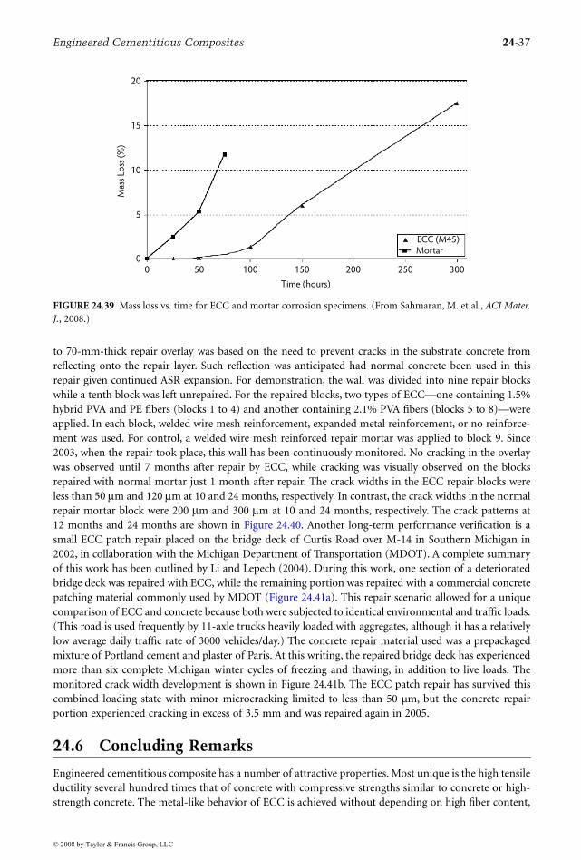
Engineered Cementitious Composites 24-37
to 70-mm-thick repair overlay was based on the need to prevent cracks in the substrate concrete fromreflecting onto the repair layer. Such reflection was anticipated had normal concrete been used in thisrepair given continued ASR expansion. For demonstration, the wall was divided into nine repair blockswhile a tenth block was left unrepaired. For the repaired blocks, two types of ECC—one containing 1.5%hybrid PVA and PE fibers (blocks 1 to 4) and another containing 2.1% PVA fibers (blocks 5 to 8)—wereapplied. In each block, welded wire mesh reinforcement, expanded metal reinforcement, or no reinforce-ment was used. For control, a welded wire mesh reinforced repair mortar was applied to block 9. Since2003, when the repair took place, this wall has been continuously monitored. No cracking in the overlaywas observed until 7 months after repair by ECC, while cracking was visually observed on the blocksrepaired with normal mortar just 1 month after repair. The crack widths in the ECC repair blocks wereless than 50 µm and 120 µm at 10 and 24 months, respectively. In contrast, the crack widths in the normalrepair mortar block were 200 µm and 300 µm at 10 and 24 months, respectively. The crack patterns at12 months and 24 months are shown in Figure 24.40. Another long-term performance verification is asmall ECC patch repair placed on the bridge deck of Curtis Road over M-14 in Southern Michigan in2002, in collaboration with the Michigan Department of Transportation (MDOT). A complete summaryof this work has been outlined by Li and Lepech (2004). During this work, one section of a deterioratedbridge deck was repaired with ECC, while the remaining portion was repaired with a commercial concretepatching material commonly used by MDOT (Figure 24.41a). This repair scenario allowed for a uniquecomparison of ECC and concrete because both were subjected to identical environmental and traffic loads.(This road is used frequently by 11-axle trucks heavily loaded with aggregates, although it has a relativelylow average daily traffic rate of 3000 vehicles/day.) The concrete repair material used was a prepackagedmixture of Portland cement and plaster of Paris. At this writing, the repaired bridge deck has experiencedmore than six complete Michigan winter cycles of freezing and thawing, in addition to live loads. Themonitored crack width development is shown in Figure 24.41b. The ECC patch repair has survived thiscombined loading state with minor microcracking limited to less than 50 µm, but the concrete repairportion experienced cracking in excess of 3.5 mm and was repaired again in 2005.
24.6 Concluding Remarks
Engineered cementitious composite has a number of attractive properties. Most unique is the high tensileductility several hundred times that of concrete with compressive strengths similar to concrete or high-strength concrete. The metal-like behavior of ECC is achieved without depending on high fiber content,
FIGURE 24.39 Mass loss vs. time for ECC and mortar corrosion specimens. (From Sahmaran, M. et al., ACI Mater.J., 2008.)
0 50 100 150 200 250 300
Time (hours)
20
15
10
5
0
Mas
s Lo
ss (
%)
ECC (M45)Mortar
© 2008 by Taylor & Francis Group, LLC
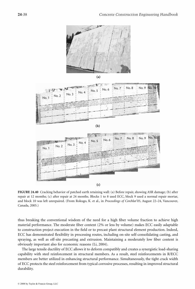
24-38 Concrete Construction Engineering Handbook
thus breaking the conventional wisdom of the need for a high fiber volume fraction to achieve highmaterial performance. The moderate fiber content (2% or less by volume) makes ECC easily adaptableto construction project execution in the field or to precast plant structural element production. Indeed,ECC has demonstrated flexibility in processing routes, including on-site self-consolidating casting, andspraying, as well as off-site precasting and extrusion. Maintaining a moderately low fiber content isobviously important also for economic reasons (Li, 2004).
The large tensile ductility of ECC allows it to deform compatibly and creates a synergistic load-sharingcapability with steel reinforcement in structural members. As a result, steel reinforcements in R/ECCmembers are better utilized in enhancing structural performance. Simultaneously, the tight crack widthof ECC protects the steel reinforcement from typical corrosive processes, resulting in improved structuraldurability.
FIGURE 24.40 Cracking behavior of patched earth retaining wall: (a) Before repair, showing ASR damage; (b) afterrepair at 12 months; (c) after repair at 24 months. Blocks 1 to 8 used ECC, block 9 used a normal repair mortar,and block 10 was left unrepaired. (From Rokugo, K. et al., in Proceedings of ConMat’05, August 22–24, Vancouver,Canada, 2005.)
No. 1No. 2
No. 3No. 4
No. 5 No. 6 No. 7 No. 8 No. 9 No. 10
No. 1No. 2 No. 3
No. 4No. 5 No. 6 No. 7 No. 8 No. 9 No. 10
(a)
(b)
(c)
© 2008 by Taylor & Francis Group, LLC
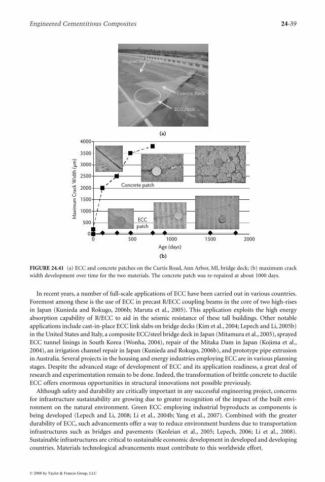
Engineered Cementitious Composites 24-39
In recent years, a number of full-scale applications of ECC have been carried out in various countries.Foremost among these is the use of ECC in precast R/ECC coupling beams in the core of two high-risesin Japan (Kunieda and Rokugo, 2006b; Maruta et al., 2005). This application exploits the high energyabsorption capability of R/ECC to aid in the seismic resistance of these tall buildings. Other notableapplications include cast-in-place ECC link slabs on bridge decks (Kim et al., 2004; Lepech and Li, 2005b)in the United States and Italy, a composite ECC/steel bridge deck in Japan (Mitamura et al., 2005), sprayedECC tunnel linings in South Korea (Wonha, 2004), repair of the Mitaka Dam in Japan (Kojima et al.,2004), an irrigation channel repair in Japan (Kunieda and Rokugo, 2006b), and prototype pipe extrusionin Australia. Several projects in the housing and energy industries employing ECC are in various planningstages. Despite the advanced stage of development of ECC and its application readiness, a great deal ofresearch and experimentation remain to be done. Indeed, the transformation of brittle concrete to ductileECC offers enormous opportunities in structural innovations not possible previously.
Although safety and durability are critically important in any successful engineering project, concernsfor infrastructure sustainability are growing due to greater recognition of the impact of the built envi-ronment on the natural environment. Green ECC employing industrial byproducts as components isbeing developed (Lepech and Li, 2008; Li et al., 2004b; Yang et al., 2007). Combined with the greaterdurability of ECC, such advancements offer a way to reduce environment burdens due to transportationinfrastructures such as bridges and pavements (Keoleian et al., 2005; Lepech, 2006; Li et al., 2008).Sustainable infrastructures are critical to sustainable economic development in developed and developingcountries. Materials technological advancements must contribute to this worldwide effort.
FIGURE 24.41 (a) ECC and concrete patches on the Curtis Road, Ann Arbor, MI, bridge deck; (b) maximum crackwidth development over time for the two materials. The concrete patch was re-repaired at about 1000 days.
4000
3500
3000
2500
2000
1500
1000
500
00 500 1000 1500 2000
Max
imu
m C
rack
Wid
th (
µm
)
Concrete patch
ECC
patch
Age (days)
(a)
(b)
© 2008 by Taylor & Francis Group, LLC
24-40 Concrete Construction Engineering Handbook
Acknowledgments
The author would like to acknowledge the research support of the National Science Foundation (theBiocomplexity, the Cyberinfrastructure, and the Civil, Mechanical and Manufacturing Innovation pro-grams) and the Michigan Department of Transportation. Many former and current students, postdoc-torates, and colleagues at the University of Michigan contributed to this work. Their devotion toadvancing infrastructure materials is greatly appreciated. Knowledge on ECC has been greatly expandedby the intense research activities of many academic and industrial groups around the world in the lastseveral years. Special thanks are extended to Dr. M. Lepech who reviewed a draft of this manuscript andprovided helpful suggestions for improvements.
References
AASHTO. 2002. Standard Method of Test for Resistance of Concrete to Chloride Ion Penetration, AASHTOT 259. American Association of State Highway and Transportation Officials, Washington, D.C.
AASHTO. 2004. LRFD Bridge Design Specifications. American Association of State Highway and Trans-portation Officials, Washington, D.C.
Allen, H.G. 1971. Stiffness and strength of two glass-fiber reinforced cement laminates. J. CompositeMater., 5(2), 194–207.
ASTM. 2003a. Standard Test Method for Resistance of Concrete to Rapid Freezing and Thawing, ASTM C666/C 666M. American Society for Testing and Materials, Philadelphia, PA.
ASTM. 2003b. Standard Test Method for Scaling Resistance of Concrete Surfaces Exposed to Deicing Chem-icals, ASTM C 672/C 672M. American Society for Testing and Materials, Philadelphia, PA.
ASTM. 2004. Standard Test Method for Measurement of Rate of Absorption of Water by Hydraulic-CementConcretes, ASTM C 1585. American Society for Testing and Materials, Philadelphia, PA.
ASTM. 2006. Standard Test Method for Density, Absorption, and Voids in Hardened Concrete, ASTM C642. American Society for Testing and Materials, Philadelphia, PA.
ASTM. 2007. Standard Test Method for Potential Alkali Reactivity of Aggregates (Mortar-Bar Method),ASTM C 1260. American Society for Testing and Materials, Philadelphia, PA.
Aveston, J., Cooper, G.A., and Kelly, A. 1971. Single and multiple fracture. In The Properties of FiberComposites, Conference Proceedings, pp. 15–24. IPC Science and Technology Press, Guildford, U.K.
Bache, H. 1981. Densified Cement/Ultra-Fine Particle-Based Materials, CBL Report No. 40. AalborgPortland, Denmark.
Beeldens, A. and Vandewalle, L. 2001. Durability of high strength concrete for highway pavement resto-ration. In Proceedings of Third International Conference on Concrete Under Severe Conditions (CON-SEC’01), June 18–20, Vancouver, Canada, pp. 1230–1238.
Billington, S.L. and Yoon, J.K. 2004. Cyclic response of precast bridge columns with ductile fiber-reinforced concrete. ASCE J. Bridge Eng., 9(4), 353–363.
Boshoff, W.P. and van Zijl, G.P.A.G. 2007. Tensile creep of SHCC. In Proceedings of the Fifth InternationalRILEM Workshop on High-Performance Fiber-Reinforced Cement Composites (HPFRCC 5), Rein-hardt, H.W. and Naaman, A.E., Eds., pp. 87–96. RILEM, Paris.
Carpinteri, A., Gamarova, P., Ferro, G., and Plizzari, G., Eds. 2007. Proceedings of 6th InternationalConference on Fracture Mechanics of Concrete and Concrete Structures (FraMCoS-6), June 17–22,Catania, Italy. Taylor & Francis, New York.
Chanvillard, G. and Rigaud, S. 2003. Complete characterization of tensile properties of ductal UHPFRCaccording to the French recommendations. In Proceedings of the Fourth International RILEMWorkshop on High-Performance Fiber-Reinforced Cement Composites (HPFRCC 4), Naaman, A.E.and Reinhardt, H.W., Eds., pp. 21–34. RILEM, Paris.
Curbach, M. and Jesse, F. 1999. High-performance textile-reinforced concrete. Struct. Eng. Int., 9(4),289–291.
© 2008 by Taylor & Francis Group, LLC
Engineered Cementitious Composites 24-41
Fischer, G. and Li, V.C. 2002a. Effect of matrix ductility on deformation behavior of steel reinforced ECCflexural members under reversed cyclic loading conditions. ACI Struct. J., 99 (6), 781–790.
Fischer, G. and Li, V.C. 2002b. Influence of matrix ductility on the tension-stiffening behavior of steelreinforced engineered cementitious composites (ECC). ACI Struct. J., 99(1), 104–111.
Fischer, G. and Li, V.C. 2003a. Deformation behavior of fiber-reinforced polymer reinforced engineeredcementitious composite (ECC) flexural members under reversed cyclic loading conditions. ACIStruct. J., 100(1), 25–35.
Fischer, G. and Li, V.C. 2003b. Intrinsic response control of moment resisting frames utilizing advancedcomposite materials and structural elements. ACI Struct. J., 100(2), 166–176.
Fischer, G. and Li, V.C., Eds. 2006. Proceedings, High-Performance Fiber-Reinforced Cementitious Com-posites (HPFRCC) in Structural Applications. RILEM, Paris.
Fischer, G., Wang, S., and Li, V.C. 2003. Design of engineered cementitious composites for processingand workability requirements. In Proceedings of the Seventh International Symposium on BrittleMatrix Composites, October 13–15, Warsaw, Poland, pp. 29–36.
Fukuyama, H., Iso, M., Ogaw, A., and Suwada, H. 2007. Mitigation of damage due to crack of RC elementsutilizing high-performance fiber-reinforced cementitious composites. In Proceedings of the FifthInternational RILEM Workshop on High-Performance Fiber-Reinforced Cement Composites(HPFRCC 5), Reinhardt, H.W. and Naaman, A.E., Eds., pp. 427–435. RILEM, Paris.
Fukuyama, H., Matsuzaki, Y., Nakano, K., and Sato, Y. 1999. Structural performance of beam elementswith PVA-ECC. In Proceedings of the Third International RILEM Workshop on High-PerformanceFiber-Reinforced Cement Composites (HPFRCC 3), Reinhardt, H.W. and Naaman, A.E., Eds., pp.531–542. Chapman & Hall, London.
Fukuyama, H., Matzuzaki, Y., Sato, Y., Iso, M., and Suwada, H. 2000. Structural performance of engineeredcementitious composite elements. In Proceedings of the 6th ASCCS International Conference onSteel–Concrete Composite Structures, March 22–24, Los Angeles, CA.
Fukuyama, H., Suwada, H., and Mukai, T. 2006. Test on high-performance wall elements with HPFRCC.In Proceedings, High-Performance Fiber-Reinforced Cementitious Composites (HPFRCC) in Struc-tural Applications, Fischer, G. and Li, V.C., Eds., pp. 365–374. RILEM, Paris.
Horikoshi, T., Ogawa, A., Saito, T., and Hoshiro, H. 2006. Properties of polyvinylalcohol fiber as rein-forcing materials for cementitious composites. In Proceedings, High-Performance Fiber-ReinforcedCementitious Composites (HPFRCC) in Structural Applications, Fischer, G. and Li, V.C., Eds., pp.145–153. RILEM, Paris.
JSCE. 2007. Recommendations for Design and Construction of High-Performance Fiber-Reinforced CementComposite with Multiple Fine Cracks (Draft), Japan Society of Civil Engineers, Tokyo [in Japanese].
Kabele, P., 2001. Assessment of Structural Performance of Engineered Cementitious Composites by ComputerSimulation, CTU Reports No. 4, Vol. 5. Czech Technical University, Prague.
Kabele, P. and Kanakubo, T. 2007. Experimental and numerical investigation of shear behavior of PVA-ECC in structural elements. In Proceedings of the Fifth International RILEM Workshop on High-Performance Fiber-Reinforced Cement Composites (HPFRCC 5), Reinhardt, H.W. and Naaman, A.E.,Eds., pp. 137–146. RILEM, Paris.
Kabele, P., Novak, L., Nemecek, J., and Pekar, J. 2007. Multiscale experimental investigation of deteriora-tion of fiber-cementitious composites in aggressive environment. In Proc. MHM 2007: InternationalConference on Modelling of Heterogeneous Materials with Applications in Construction and BiomedicalEngineering, June 25–27, Prague, Jirasek, M., Bittnar, Z., and Mang, H., Eds., pp. 270–271.
Kamal, A., Kunieda, M., Ueda, N., and Nakamura, H. 2007. Assessment of crack elongation performancein RC beam repaired by UHP–SHCC. In Proceedings of the Ninth International JSCE SummerSymposium, September 18, Yokohama National University, Japan.
Kanakubo, T. 2006. Tensile characteristics: evaluation method for DFRCC. J. Adv. Concrete Technol., 4(1),3–17.
Kanda, T. and Li, V.C. 1999. A new micromechanics design theory for pseudo strain hardening cemen-titious composite. ASCE J. Eng. Mech., 125(4), 373–381.
© 2008 by Taylor & Francis Group, LLC
24-42 Concrete Construction Engineering Handbook
Kanda, T. and Li, V.C. 2006. Practical design criteria for saturated pseudo strain hardening behavior inECC. J. Adv. Concrete Technol., 4(1), 59–72.
Kanda, T., Watanabe, S., and Li, V.C. 1998. Application of pseudo strain hardening cementitious com-posites to shear resistant structural elements. In Fracture Mechanics of Concrete Structures: Proceed-ings FramCoS-3, pp. 1477–1490. AEDIFICATIO Publishers, Freiberg, Germany.
Kanda, T., Saito, T., Sakat, N., and Hiraishi, H. 2001. Basic properties of sprayed repair material basedon a highly ductile FRC with PVA fiber. Proc. Annu. Meet. JCI, 25(1), 475–480.
Kanda, T., Kanakubo, T., Nagai, S., and Maruta, M. 2006a. Technical consideration in producing ECCpre-cast structural elements. In Proceedings, High-Performance Fiber-Reinforced Cementitious Com-posites (HPFRCC) in Structural Applications, Fischer, G. and Li, V.C., Eds., pp. 229–242. RILEM,Paris.
Kanda, T., Tomoe, S., Nagai, S., Maruta, M., Kanakubo, T., and Shimizu, K. 2006b. Full-scale pro-cessing investigation for ECC pre-cast structural elements. J. Asian Architect. Build. Eng., 5(2),333–340.
Keoleian, G.A., Kendall, A., Dettling, J.E., Smith, V.M., Chandler, R., Lepech, M.D., and Li, V.C. 2005.Life cycle modeling of concrete bridge design: comparison of engineered cementitious compositelink slabs and conventional steel expansion joints. ASCE J. Infrastructure Syst., 11(1), 51–60.
Kesner, K.E. and Billington, S.L. 2005. Investigation of infill panels made from engineered cementitiouscomposites for seismic strengthening and retrofit. ASCE J. Struct. Eng., 131(11), 712–720.
Kim, Y.Y., Kong, H.J., and Li, V.C. 2003. Design of engineered cementitious composite (ECC) suitablefor wet-mix shotcreting. ACI Mater. J., 100(6), 511–518.
Kim, Y.Y., Fischer, G., and Li, V.C. 2004. Performance of bridge deck link slabs designed with ductileECC. ACI Struct. J., 101(6), 792–801.
Kojima, S., Sakat, N., Kanda, T., and Hiraishi, T. 2004. Application of direct sprayed ECC for retrofittingdam structure surface: application for Mitaka Dam. Concrete J., 42(5), 35–39 [in Japanese].
Kong, H.J., Bike, S., and Li, V.C. 2003. Development of a self-compacting engineered cementitiouscomposite employing electrosteric dispersion/stabilization. J. Cement Concrete Comp., 25(3),301–309.
Krenchel, H. and Stang, H. 1989. Stable microcracking in cementitious materials. In Brittle MatrixComposites 2, Brandt, A.M. and Marshall, J.H., Eds., pp. 20–33. Elsevier, Amsterdam.
Kunieda, M. and Rokugo, K. 2006a. Measurement of crack opening behavior within ECC under bendingmoment. In Proceedings, High-Performance Fiber-Reinforced Cementitious Composites (HPFRCC)in Structural Applications, Fischer, G. and Li, V.C., Eds., pp. 313–322. RILEM, Paris.
Kunieda, M. and Rokugo, K. 2006b. Recent progress on HPFRCC in Japan: required performance andapplications. J. Adv. Concrete Technol., 4(1), 19–33.
Lankard, D.R. 1986. Preparation, properties and applications of cement based composites containing5–20 percent steel fiber reinforcement. In Steel Fiber Concrete, Shah, S.P. and Skarendahl, A., Eds.Elsevier, Amsterdam.
Lepech, M.D. 2006. A Paradigm for Integrated Structures and Materials Design for Sustainable Trans-portation Infrastructure, Ph.D. thesis. University of Michigan, Ann Arbor.
Lepech, M.D. and Li, V.C. 2005a. Water permeability of cracked cementitious composites. In Proceedingsof the 11th International Conference on Fracture (ICF XI), March 20–25, Torino, Italy.
Lepech, M.D. and Li, V.C. 2005b. Design and field demonstration of ECC link slabs for jointless bridgedecks. In Proceedings of ConMat’05, August 22–24, Vancouver, Canada.
Lepech, M.D. and Li, V.C. 2008. Large scale processing of engineered cementitious composites. ACI Mater.J., accepted.
Lepech, M.D., Li, V.C., Robertson, R.E., and Keoleian, G.A. 2007. Design of ductile engineered cemen-titious composites for improved sustainability. ACI Mater. J., submitted.
Leung, C.K.Y., Cheung, A.K.F., and Zhang, X. 2006. Partial use of pseudo-ductile cementitiouscomposites in concrete components to resist concentrated stress, Key Eng. Mater., 312,319–324.
© 2008 by Taylor & Francis Group, LLC
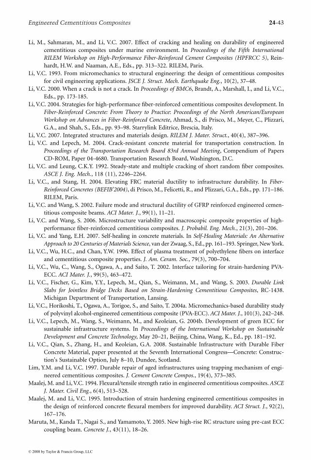
Engineered Cementitious Composites 24-43
Li, M., Sahmaran, M., and Li, V.C. 2007. Effect of cracking and healing on durability of engineeredcementitious composites under marine environment. In Proceedings of the Fifth InternationalRILEM Workshop on High-Performance Fiber-Reinforced Cement Composites (HPFRCC 5), Rein-hardt, H.W. and Naaman, A.E., Eds., pp. 313–322. RILEM, Paris.
Li, V.C. 1993. From micromechanics to structural engineering: the design of cementitious compositesfor civil engineering applications. JSCE J. Struct. Mech. Earthquake Eng., 10(2), 37–48.
Li, V.C. 2000. When a crack is not a crack. In Proceedings of BMC6, Brandt, A., Marshall, I., and Li, V.C.,Eds., pp. 173-185.
Li, V.C. 2004. Strategies for high-performance fiber-reinforced cementitious composites development. InFiber-Reinforced Concrete: From Theory to Practice: Proceedings of the North American/EuropeanWorkshop on Advances in Fiber-Reinforced Concrete, Ahmad, S., di Prisco, M., Meyer, C., Plizzari,G.A., and Shah, S., Eds., pp. 93–98. Starrylink Editrice, Brescia, Italy.
Li, V.C. 2007. Integrated structures and materials design. RILEM J. Mater. Struct., 40(4), 387–396.Li, V.C. and Lepech, M. 2004. Crack-resistant concrete material for transportation construction. In
Proceedings of the Transportation Research Board 83rd Annual Meeting, Compendium of PapersCD-ROM, Paper 04-4680. Transportation Research Board, Washington, D.C.
Li, V.C. and Leung, C.K.Y. 1992. Steady-state and multiple cracking of short random fiber composites.ASCE J. Eng. Mech., 118 (11), 2246–2264.
Li, V.C., and Stang, H. 2004. Elevating FRC material ductility to infrastructure durability. In Fiber-Reinforced Concretes (BEFIB’2004), di Prisco, M., Felicetti, R., and Plizzari, G.A., Eds., pp. 171–186.RILEM, Paris.
Li, V.C. and Wang, S. 2002. Failure mode and structural ductility of GFRP reinforced engineered cemen-titious composite beams. ACI Mater. J., 99(1), 11–21.
Li, V.C. and Wang, S. 2006. Microstructure variability and macroscopic composite properties of high-performance fiber-reinforced cementitious composites. J. Probabil. Eng. Mech., 21(3), 201–206.
Li, V.C. and Yang, E.H. 2007. Self-healing in concrete materials. In Self-Healing Materials: An AlternativeApproach to 20 Centuries of Materials Science, van der Zwaag, S., Ed., pp. 161–193. Springer, New York.
Li, V.C., Wu, H.C., and Chan, Y.W. 1996. Effect of plasma treatment of polyethylene fibers on interfaceand cementitious composite properties. J. Am. Ceram. Soc., 79(3), 700–704.
Li, V.C., Wu, C., Wang, S., Ogawa, A., and Saito, T. 2002. Interface tailoring for strain-hardening PVA-ECC. ACI Mater. J., 99(5), 463–472.
Li, V.C., Fischer, G., Kim, Y.Y., Lepech, M., Qian, S., Weimann, M., and Wang, S. 2003. Durable LinkSlabs for Jointless Bridge Decks Based on Strain-Hardening Cementitious Composites, RC-1438.Michigan Department of Transportation, Lansing.
Li, V.C., Horikoshi, T., Ogawa, A., Torigoe, S., and Saito, T. 2004a. Micromechanics-based durability studyof polyvinyl alcohol-engineered cementitious composite (PVA-ECC). ACI Mater. J., 101(3), 242–248.
Li, V.C., Lepech, M., Wang, S., Weimann, M., and Keoleian, G. 2004b. Development of green ECC forsustainable infrastructure systems. In Proceedings of the International Workshop on SustainableDevelopment and Concrete Technology, May 20–21, Beijing, China, Wang, K., Ed., pp. 181–192.
Li, V.C., Qian, S., Zhang, H., and Keoleian, G.A. 2008. Sustainable Infrastructure with Durable FiberConcrete Material, paper presented at the Seventh International Congress—Concrete: Construc-tion's Sustainable Option, July 8–10, Dundee, Scotland.
Lim, Y.M. and Li, V.C. 1997. Durable repair of aged infrastructures using trapping mechanism of engi-neered cementitious composites. J. Cement Concrete Compos., 19(4), 373–385.
Maalej, M. and Li, V.C. 1994. Flexural/tensile strength ratio in engineered cementitious composites. ASCEJ. Mater. Civil Eng., 6(4), 513–528.
Maalej, M. and Li, V.C. 1995. Introduction of strain hardening engineered cementitious composites inthe design of reinforced concrete flexural members for improved durability. ACI Struct. J., 92(2),167–176.
Maruta, M., Kanda T., Nagai S., and Yamamoto, Y. 2005. New high-rise RC structure using pre-cast ECCcoupling beam. Concrete J., 43(11), 18–26.
© 2008 by Taylor & Francis Group, LLC
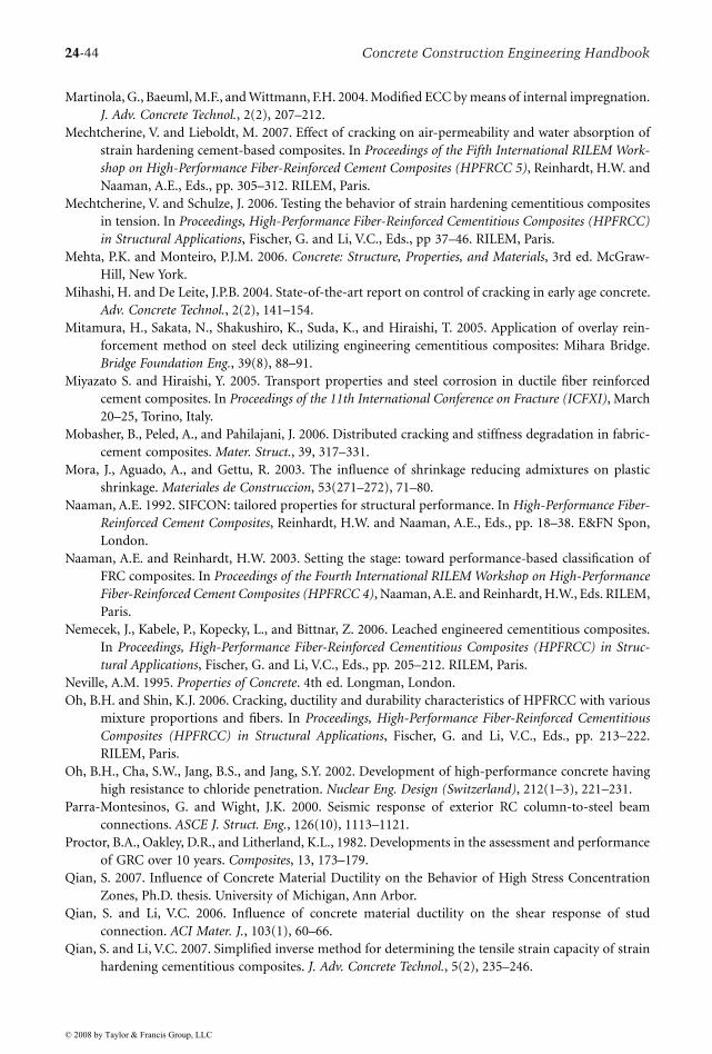
24-44 Concrete Construction Engineering Handbook
Martinola, G., Baeuml, M.F., and Wittmann, F.H. 2004. Modified ECC by means of internal impregnation.J. Adv. Concrete Technol., 2(2), 207–212.
Mechtcherine, V. and Lieboldt, M. 2007. Effect of cracking on air-permeability and water absorption ofstrain hardening cement-based composites. In Proceedings of the Fifth International RILEM Work-shop on High-Performance Fiber-Reinforced Cement Composites (HPFRCC 5), Reinhardt, H.W. andNaaman, A.E., Eds., pp. 305–312. RILEM, Paris.
Mechtcherine, V. and Schulze, J. 2006. Testing the behavior of strain hardening cementitious compositesin tension. In Proceedings, High-Performance Fiber-Reinforced Cementitious Composites (HPFRCC)in Structural Applications, Fischer, G. and Li, V.C., Eds., pp 37–46. RILEM, Paris.
Mehta, P.K. and Monteiro, P.J.M. 2006. Concrete: Structure, Properties, and Materials, 3rd ed. McGraw-Hill, New York.
Mihashi, H. and De Leite, J.P.B. 2004. State-of-the-art report on control of cracking in early age concrete.Adv. Concrete Technol., 2(2), 141–154.
Mitamura, H., Sakata, N., Shakushiro, K., Suda, K., and Hiraishi, T. 2005. Application of overlay rein-forcement method on steel deck utilizing engineering cementitious composites: Mihara Bridge.Bridge Foundation Eng., 39(8), 88–91.
Miyazato S. and Hiraishi, Y. 2005. Transport properties and steel corrosion in ductile fiber reinforcedcement composites. In Proceedings of the 11th International Conference on Fracture (ICFXI), March20–25, Torino, Italy.
Mobasher, B., Peled, A., and Pahilajani, J. 2006. Distributed cracking and stiffness degradation in fabric-cement composites. Mater. Struct., 39, 317–331.
Mora, J., Aguado, A., and Gettu, R. 2003. The influence of shrinkage reducing admixtures on plasticshrinkage. Materiales de Construccion, 53(271–272), 71–80.
Naaman, A.E. 1992. SIFCON: tailored properties for structural performance. In High-Performance Fiber-Reinforced Cement Composites, Reinhardt, H.W. and Naaman, A.E., Eds., pp. 18–38. E&FN Spon,London.
Naaman, A.E. and Reinhardt, H.W. 2003. Setting the stage: toward performance-based classification ofFRC composites. In Proceedings of the Fourth International RILEM Workshop on High-PerformanceFiber-Reinforced Cement Composites (HPFRCC 4), Naaman, A.E. and Reinhardt, H.W., Eds. RILEM,Paris.
Nemecek, J., Kabele, P., Kopecky, L., and Bittnar, Z. 2006. Leached engineered cementitious composites.In Proceedings, High-Performance Fiber-Reinforced Cementitious Composites (HPFRCC) in Struc-tural Applications, Fischer, G. and Li, V.C., Eds., pp. 205–212. RILEM, Paris.
Neville, A.M. 1995. Properties of Concrete. 4th ed. Longman, London.Oh, B.H. and Shin, K.J. 2006. Cracking, ductility and durability characteristics of HPFRCC with various
mixture proportions and fibers. In Proceedings, High-Performance Fiber-Reinforced CementitiousComposites (HPFRCC) in Structural Applications, Fischer, G. and Li, V.C., Eds., pp. 213–222.RILEM, Paris.
Oh, B.H., Cha, S.W., Jang, B.S., and Jang, S.Y. 2002. Development of high-performance concrete havinghigh resistance to chloride penetration. Nuclear Eng. Design (Switzerland), 212(1–3), 221–231.
Parra-Montesinos, G. and Wight, J.K. 2000. Seismic response of exterior RC column-to-steel beamconnections. ASCE J. Struct. Eng., 126(10), 1113–1121.
Proctor, B.A., Oakley, D.R., and Litherland, K.L., 1982. Developments in the assessment and performanceof GRC over 10 years. Composites, 13, 173–179.
Qian, S. 2007. Influence of Concrete Material Ductility on the Behavior of High Stress ConcentrationZones, Ph.D. thesis. University of Michigan, Ann Arbor.
Qian, S. and Li, V.C. 2006. Influence of concrete material ductility on the shear response of studconnection. ACI Mater. J., 103(1), 60–66.
Qian, S. and Li, V.C. 2007. Simplified inverse method for determining the tensile strain capacity of strainhardening cementitious composites. J. Adv. Concrete Technol., 5(2), 235–246.
© 2008 by Taylor & Francis Group, LLC
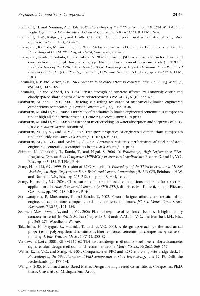
Engineered Cementitious Composites 24-45
Reinhardt, H. and Naaman, A.E., Eds. 2007. Proceedings of the Fifth International RILEM Workshop onHigh-Performance Fiber-Reinforced Cement Composites (HPFRCC 5). RILEM, Paris.
Reinhardt, H.W., Krüger, M., and Große, C.U. 2003. Concrete prestressed with textile fabric. J. Adv.Concrete Technol., 1(3), 231–239.
Rokugo, K., Kunieda, M., and Lim, S.C. 2005. Patching repair with ECC on cracked concrete surface. InProceedings of ConMat’05, August 22–24, Vancouver, Canada.
Rokugo, K., Kanda, T., Yokota, H., and Sakata, N. 2007. Outline of JSCE recommendation for design andconstruction of multiple fine cracking type fiber reinforced cementitious composite (HPFRCC).In Proceedings of the Fifth International RILEM Workshop on High-Performance Fiber-ReinforcedCement Composites (HPFRCC 5), Reinhardt, H.W. and Naaman, A.E., Eds., pp. 203–212. RILEM,Paris.
Romualdi, N.P. and Batson, G.B. 1963. Mechanics of crack arrest in concrete. Proc. ASCE Eng. Mech. J.,89(EM3), 147–168.
Romualdi, J.P. and Mandel, J.A. 1964. Tensile strength of concrete affected by uniformly distributedclosely spaced short lengths of wire reinforcement. Proc. ACI J., 61(6), 657–671.
Sahmaran, M. and Li, V.C. 2007. De-icing salt scaling resistance of mechanically loaded engineeredcementitious composites. J. Cement Concrete Res., 37, 1035–1046.
Sahmaran, M. and Li, V.C. 2008a. Durability of mechanically loaded engineered cementitious compositesunder high alkaline environment. J. Cement Concrete Compos., in print.
Sahmaran, M. and Li, V.C. 2008b. Influence of microcracking on water absorption and sorptivity of ECC.RILEM J. Mater. Struct., submitted.
Sahmaran, M., Li, M., and Li, V.C. 2007. Transport properties of engineered cementitious compositesunder chloride exposure. ACI Mater. J., 104(6), 604–611.
Sahmaran, M., Li, V.C., and Andrade, C. 2008. Corrosion resistance performance of steel-reinforcedengineered cementitious composites beams. ACI Mater. J., in print.
Shimizu, K., Kanakubo, T., Kanda, T., and Nagai, S. 2006. In Proceedings, High-Performance Fiber-Reinforced Cementitious Composites (HPFRCC) in Structural Applications, Fischer, G. and Li, V.C.,Eds., pp. 443–451. RILEM, Paris.
Stang, H. and Li, V.C. 1999. Extrusion of ECC-Material. In Proceedings of the Third International RILEMWorkshop on High-Performance Fiber-Reinforced Cement Composites (HPFRCC3), Reinhardt, H.W.and Naaman, A.E., Eds., pp. 203–212. Chapman & Hall, London.
Stang, H. and Li, V.C. 2004. Classification of fiber-reinforced cementitious materials for structuralapplications. In Fiber-Reinforced Concretes (BEFIB’2004), di Prisco, M., Felicetti, R., and Plizzari,G.A., Eds., pp. 197–218. RILEM, Paris.
Suthiwarapirak, P., Matsumoto, T., and Kanda, T., 2002. Flexural fatigue failure characteristics of anengineered cementitious composite and polymer cement mortars. JSCE J. Mater. Conc. Struct.Pavements, 718(57), 121–134.
Szerszen, M.M., Szwed, A., and Li, V.C. 2006. Flexural response of reinforced beam with high ductilityconcrete material. In Brittle Matrix Composites 8, Brandt, A.M., Li, V.C., and Marshall, I.H., Eds.,pp. 263–274. Woodhead, Warsaw.
Takashima, H., Miyagai, K., Hashida, T., and Li, V.C. 2003. A design approach for the mechanicalproperties of polypropylene discontinuous fiber reinforced cementitious composites by extrusionmolding. J. Eng. Fracture Mech., 70(7–8), 853–870.
Vandewalle, L. et al. 2003. RILEM TC 162-TDF: test and design methods for steel fibre reinforced concrete:sigma-epsilon-design method—final recommendation. Mater. Struct., 36(262), 560–567.
Walter, R., Li, V.C., and Stang, H. 2004. Comparison of FRC and ECC in a composite bridge deck. InProceedings of the 5th International PhD Symposium in Civil Engineering, June 17–19, Delft, theNetherlands, pp. 477-484.
Wang, S. 2005. Micromechanics-Based Matrix Design for Engineered Cementitious Composites, Ph.D.thesis, University of Michigan, Ann Arbor.
© 2008 by Taylor & Francis Group, LLC
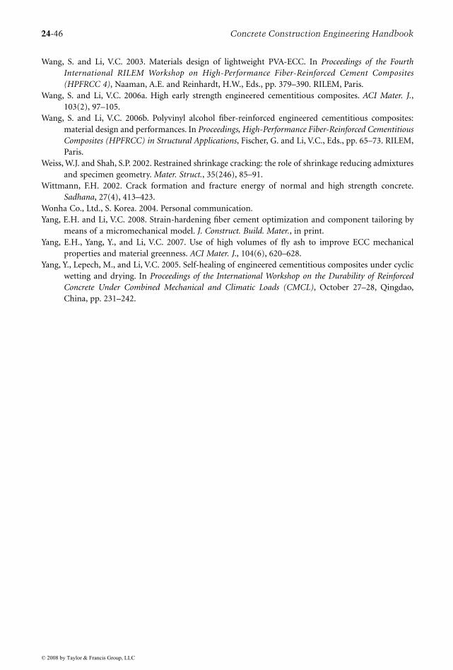
24-46 Concrete Construction Engineering Handbook
Wang, S. and Li, V.C. 2003. Materials design of lightweight PVA-ECC. In Proceedings of the FourthInternational RILEM Workshop on High-Performance Fiber-Reinforced Cement Composites(HPFRCC 4), Naaman, A.E. and Reinhardt, H.W., Eds., pp. 379–390. RILEM, Paris.
Wang, S. and Li, V.C. 2006a. High early strength engineered cementitious composites. ACI Mater. J.,103(2), 97–105.
Wang, S. and Li, V.C. 2006b. Polyvinyl alcohol fiber-reinforced engineered cementitious composites:material design and performances. In Proceedings, High-Performance Fiber-Reinforced CementitiousComposites (HPFRCC) in Structural Applications, Fischer, G. and Li, V.C., Eds., pp. 65–73. RILEM,Paris.
Weiss, W.J. and Shah, S.P. 2002. Restrained shrinkage cracking: the role of shrinkage reducing admixturesand specimen geometry. Mater. Struct., 35(246), 85–91.
Wittmann, F.H. 2002. Crack formation and fracture energy of normal and high strength concrete.Sadhana, 27(4), 413–423.
Wonha Co., Ltd., S. Korea. 2004. Personal communication.Yang, E.H. and Li, V.C. 2008. Strain-hardening fiber cement optimization and component tailoring by
means of a micromechanical model. J. Construct. Build. Mater., in print.Yang, E.H., Yang, Y., and Li, V.C. 2007. Use of high volumes of fly ash to improve ECC mechanical
properties and material greenness. ACI Mater. J., 104(6), 620–628.Yang, Y., Lepech, M., and Li, V.C. 2005. Self-healing of engineered cementitious composites under cyclic
wetting and drying. In Proceedings of the International Workshop on the Durability of ReinforcedConcrete Under Combined Mechanical and Climatic Loads (CMCL), October 27–28, Qingdao,China, pp. 231–242.
© 2008 by Taylor & Francis Group, LLC
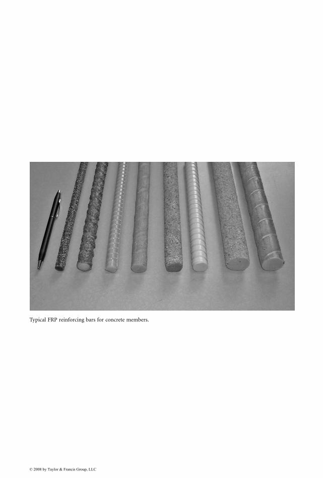
Typical FRP reinforcing bars for concrete members.
© 2008 by Taylor & Francis Group, LLC