Embed Size (px)
Citation preview
Technical Manual No. IOT4150C Effective 7/21/03
REV LEVEL - Printed August 29, 2003
Engineered Process Solutions Group
33 CENTERVILLE ROADLANCASTER PA 17603-2064
TEL: (717) 509-2200FAX: (717) 509-2336
INSTALLATION, OPERATION AND MAINTENANCE INSTRUCTIONS
MODEL T4155C & T4156C
Skotch Trifecta GAS VALVE SYSTEM
WARNING
Valves and valve actuators supplied by Engineered Process Solutions Group are designedand manufactured using good workmanship and materials, and they meet the applicableindustry standards. These valves are available with components of various materials, andthey should be used only in services recommended herein or by a company valve engineer.Misapplication of the product may result in injuries or property damage. A selection ofvalve components of the proper material consistent with the particular performancerequirement, is important for proper application.
Examples of the misapplication or misuse of a valve or valve actuator includes use in anapplication that exceeds the pressure/temperature rating, or failure to maintain theequipment as recommended.
Technical Manual No. IOT4150C Effective 7/21/03
REV LEVEL - Printed August 29, 2003
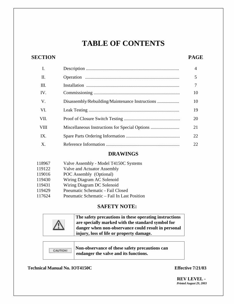
TABLE OF CONTENTS
SECTION PAGE
I. Description ................................................................................. 4
II. Operation .................................................................................. 5
III. Installation ................................................................................. 7
IV. Commissioning ........................................................................... 10
V. Disassembly/Rebuilding/Maintenance Instructions ................... 10
VI. Leak Testing ............................................................................... 19
VII. Proof of Closure Switch Testing ................................................. 20
VIII Miscellaneous Instructions for Special Options ......................... 21
IX. Spare Parts Ordering Information ............................................... 22
X. Reference Information ................................................................ 22
DRAWINGS
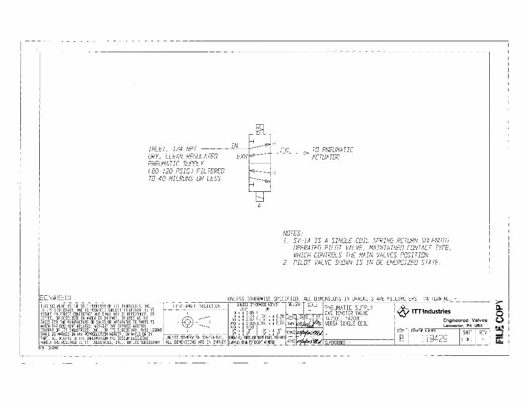
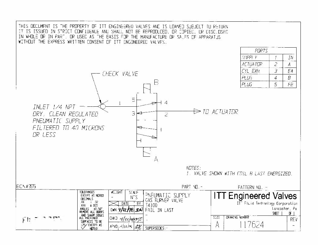
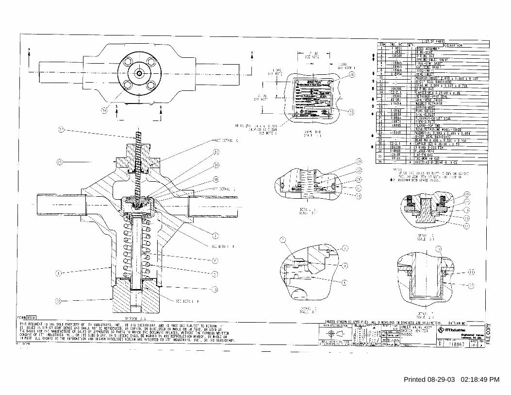
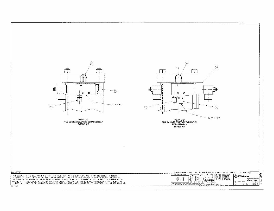
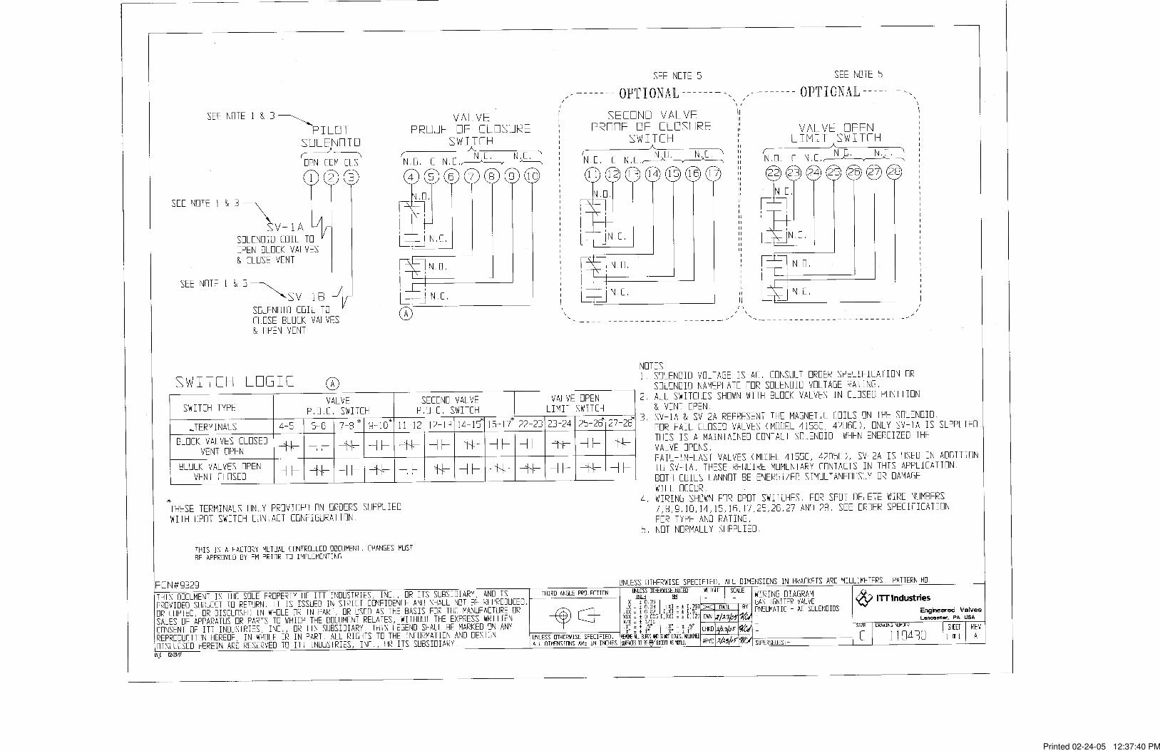
118967 Valve Assembly - Model T4150C Systems119122 Valve and Actuator Assembly119016 POC Assembly (Optional)119430 Wiring Diagram AC Solenoid119431 Wiring Diagram DC Solenoid119429 Pneumatic Schematic - Fail Closed117624 Pneumatic Schematic – Fail In Last Position
SAFETY NOTE:
The safety precautions in these operating instructionsare specially marked with the standard symbol fordanger when non-observance could result in personalinjury, loss of life or property damage.
Non-observance of these safety precautions canendanger the valve and its functions.

ITT Engineered Valves Page 4 of 22
Technical Manual No. IOT4150C Effective 7/21/03
REV LEVEL –Printed August 29, 2003
I. DESCRIPTION
The Model T4150C Skotch® Burner Valve System provides all the isolation and ventingfunctions necessary for automated operation of gas-fired burners in utility and industrialpower plants. This includes double block of the main gas line and venting the chamberbetween blocks to atmosphere. Hence, the term "Double Block and Vent" or “DoubleBlock and Bleed”. The vents are sized in accordance to IRI’s (Industrial Risk Insurers)and NFPA (National Fire Protections Association) recommended vent sizes. To satisfycode requirements, a Proof of Closure (POC) switch utilizing valve seal overtravel issupplied as standard to prove the valve is closed. Optional switches to monitor valveopen position and a second Proof of Closure (POC) can offer added feedback for plantDCS systems.
The Model T4155C valve system, which is the Fail-in-Last Position model, utilizes a dualcoil momentary contact pilot solenoid for pneumatic operation and requires compressedair and electric power to open and close. The system fails in the last position on loss ofpneumatic or electric power. It will not hold this position indefinitely if air is lost.
Due to the failure mode, Model T4155C valve systems can never be Factory Mutual (FM)approved.
The Model T4156C valve system, which is the Fail Closed model, utilizes a single coilmaintain contact spring return pilot solenoid for pneumatic operation and requirescompressed air and electric power to open. The system closes on a loss of pneumatic orelectric power.
Model T4156C valves incorporating specific configurations may be Factory Mutualapproved for Natural Gas Safety Shutoff Valves per FM Approval Standard Class 7400.Valves configured for FM Approval are tagged as such.
ITT Engineered Valves Page 5 of 22
Technical Manual No. IOT4150C Effective 7/21/03
REV LEVEL –Printed August 29, 2003
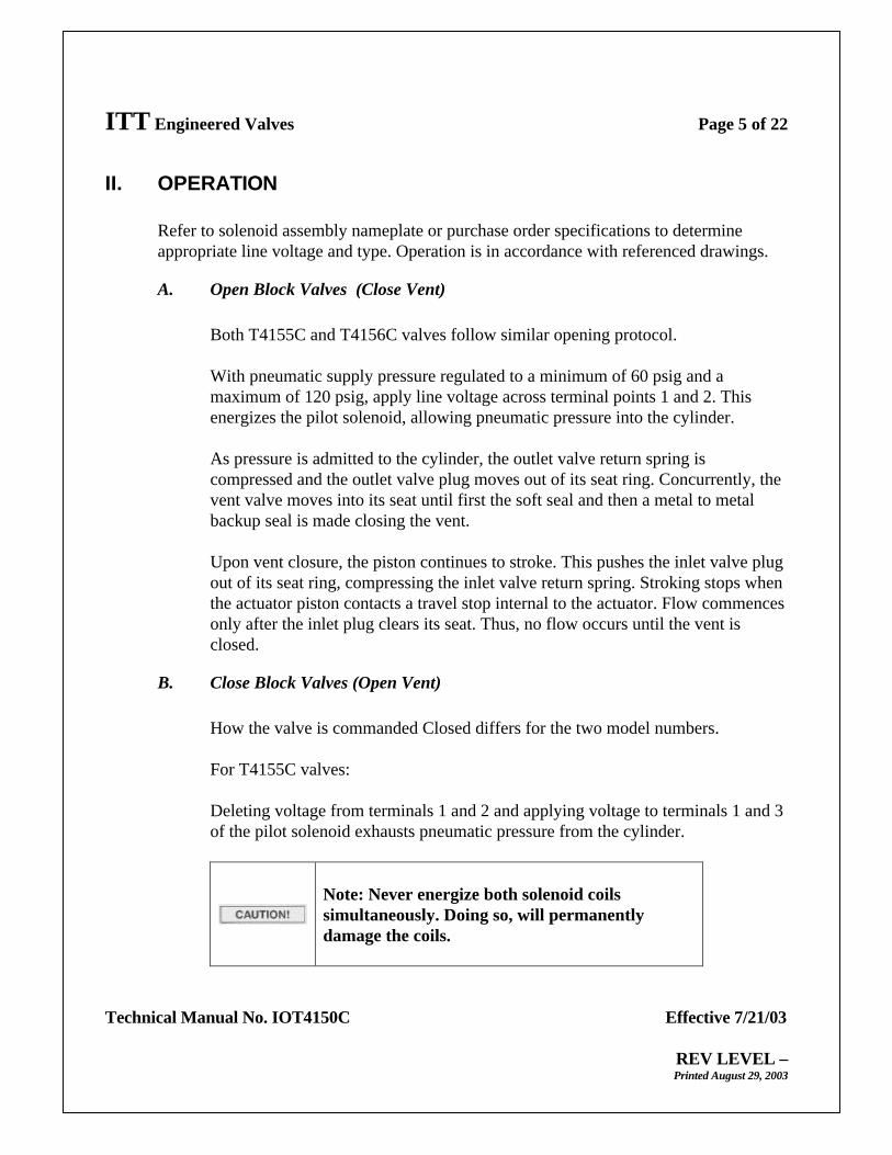
II. OPERATION
Refer to solenoid assembly nameplate or purchase order specifications to determineappropriate line voltage and type. Operation is in accordance with referenced drawings.
A. Open Block Valves (Close Vent)
Both T4155C and T4156C valves follow similar opening protocol.
With pneumatic supply pressure regulated to a minimum of 60 psig and amaximum of 120 psig, apply line voltage across terminal points 1 and 2. Thisenergizes the pilot solenoid, allowing pneumatic pressure into the cylinder.
As pressure is admitted to the cylinder, the outlet valve return spring iscompressed and the outlet valve plug moves out of its seat ring. Concurrently, thevent valve moves into its seat until first the soft seal and then a metal to metalbackup seal is made closing the vent.
Upon vent closure, the piston continues to stroke. This pushes the inlet valve plugout of its seat ring, compressing the inlet valve return spring. Stroking stops whenthe actuator piston contacts a travel stop internal to the actuator. Flow commencesonly after the inlet plug clears its seat. Thus, no flow occurs until the vent isclosed.
B. Close Block Valves (Open Vent)
How the valve is commanded Closed differs for the two model numbers.
For T4155C valves:
Deleting voltage from terminals 1 and 2 and applying voltage to terminals 1 and 3of the pilot solenoid exhausts pneumatic pressure from the cylinder.
Note: Never energize both solenoid coilssimultaneously. Doing so, will permanentlydamage the coils.
ITT Engineered Valves Page 6 of 22
Technical Manual No. IOT4150C Effective 7/21/03
REV LEVEL –Printed August 29, 2003
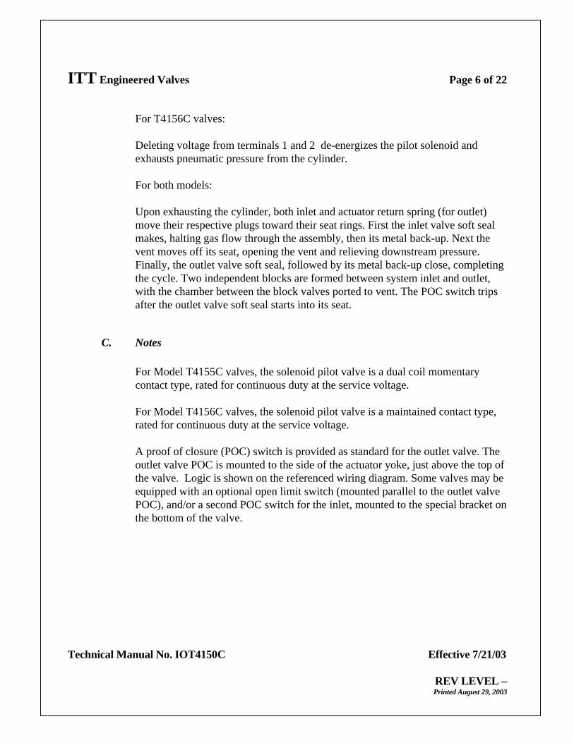
For T4156C valves:
Deleting voltage from terminals 1 and 2 de-energizes the pilot solenoid andexhausts pneumatic pressure from the cylinder.
For both models:
Upon exhausting the cylinder, both inlet and actuator return spring (for outlet)move their respective plugs toward their seat rings. First the inlet valve soft sealmakes, halting gas flow through the assembly, then its metal back-up. Next thevent moves off its seat, opening the vent and relieving downstream pressure.Finally, the outlet valve soft seal, followed by its metal back-up close, completingthe cycle. Two independent blocks are formed between system inlet and outlet,with the chamber between the block valves ported to vent. The POC switch tripsafter the outlet valve soft seal starts into its seat.
C. Notes
For Model T4155C valves, the solenoid pilot valve is a dual coil momentarycontact type, rated for continuous duty at the service voltage.
For Model T4156C valves, the solenoid pilot valve is a maintained contact type,rated for continuous duty at the service voltage.
A proof of closure (POC) switch is provided as standard for the outlet valve. Theoutlet valve POC is mounted to the side of the actuator yoke, just above the top ofthe valve. Logic is shown on the referenced wiring diagram. Some valves may beequipped with an optional open limit switch (mounted parallel to the outlet valvePOC), and/or a second POC switch for the inlet, mounted to the special bracket onthe bottom of the valve.
ITT Engineered Valves Page 7 of 22
Technical Manual No. IOT4150C Effective 7/21/03
REV LEVEL –Printed August 29, 2003
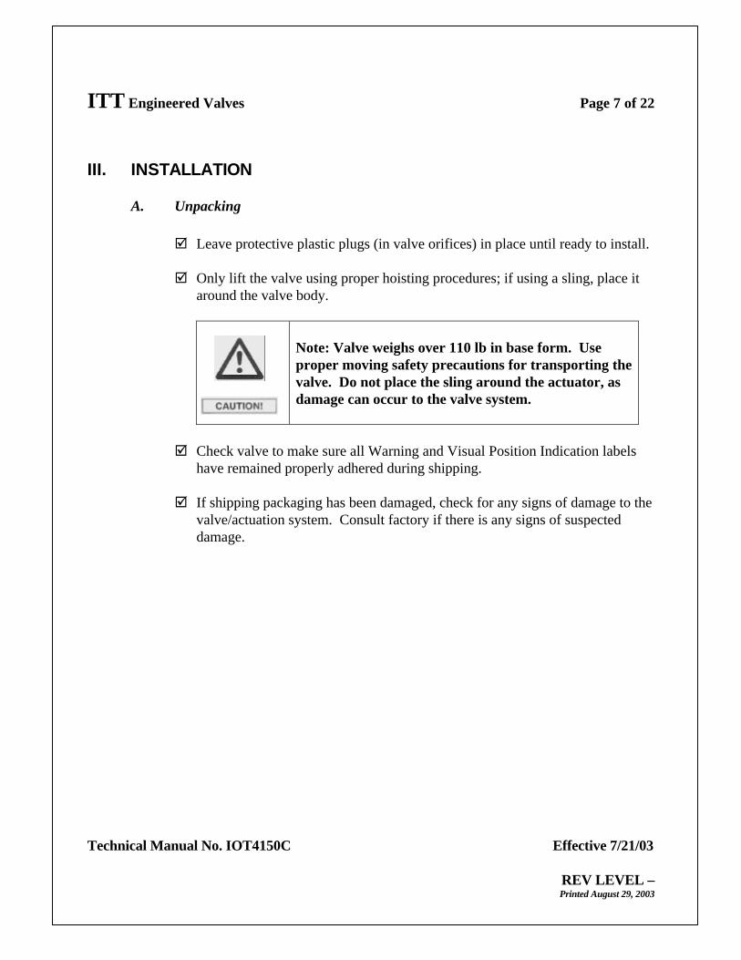
III. INSTALLATION
A. Unpacking
þ Leave protective plastic plugs (in valve orifices) in place until ready to install.
þ Only lift the valve using proper hoisting procedures; if using a sling, place itaround the valve body.
Note: Valve weighs over 110 lb in base form. Useproper moving safety precautions for transporting thevalve. Do not place the sling around the actuator, asdamage can occur to the valve system.
þ Check valve to make sure all Warning and Visual Position Indication labelshave remained properly adhered during shipping.
þ If shipping packaging has been damaged, check for any signs of damage to thevalve/actuation system. Consult factory if there is any signs of suspecteddamage.
ITT Engineered Valves Page 8 of 22
Technical Manual No. IOT4150C Effective 7/21/03
REV LEVEL –Printed August 29, 2003
B. Valve Installation
þ Verify no debris or foreign objects are inside the valve.
þ Purge the gas line prior to installing the valve.
Prior to installation and/or start-up, piping should beverified as being free of dirt, grit, welding slag, orother particulate contamination. Failure to do so mayresult in damage to valve internals.
þ Verify proper pipe connections are available for the valve. Proper vent pipesizing per NFPA 85 needs to be verified. The T4150C Skotch Trifecta ValveSystem is typically supplied with a female NPT vent connection and spigotinlet and outlet connections. (Note: Other end configurations available uponrequest.) Refer to order specification or purchase order specifications for typesupplied. Valve installation should be in accordance with standard practicesfor end connection provided. Flanges are raised face carbon steel per ANSIB16.5. Threads are per ANSI B2.1. Ensure the weight of the system isproperly supported to prevent excessive stresses. (Piping supports should bedesigned for a base valve weight slightly exceeding 110 lb – options can addto this weight). Valve may be installed in any orientation. Ensure flowdirection is appropriate for intended installation. Valves incorporating weldedends should follow special precaution to insure weld heat does not damage thevalve seals and gaskets. Temperatures in these areas should be kept below200° F.
Vent pipe size should be equivalent to the vent fittingsize supplied. Reducing vent size may result ininsufficient flow capacity. Under NO circumstanceshould the vent be blocked or plugged.
ITT Engineered Valves Page 9 of 22
Technical Manual No. IOT4150C Effective 7/21/03
REV LEVEL –Printed August 29, 2003
C. Pneumatic/Electrical Hook Up
Utilities required for operation are electrical power and clean dry compressed air.Wiring should be in accordance with referenced drawings and all applicablecodes. Supply air should be filtered to 40 microns minimum and connected perreferenced drawing.
þ Purge all air lines prior to connecting solenoids.
Historically many problems at start-up are due tomishandling of the valve and poor purging of the fueland pneumatic control lines.
þ Assure that pneumatic air supply to solenoid does not exceed 120 psig. Afiltered, regulated supply air pressure between 60 and 120 psig needs to beprovided for the valve for proper operation.
Failure to maintain proper pneumatic air linepressure could result in damage to the valve.
þ Use suitable thread sealing compound only. Do not use PTFE tape.
The exhaust side of the solenoid should not berestricted. This will slow the closing rate of the valve. Valve is supplied with an appropriate exhaustingmuffler that ensures proper closing rate. Pleaseconsult the factory for any solenoid replacement parts.
Note: Some assemblies may include a filter regulator (Optional).

ITT Engineered Valves Page 10 of 22
Technical Manual No. IOT4150C Effective 7/21/03
REV LEVEL –Printed August 29, 2003
IV. COMMISSIONING
þ Confirm that all valve connections have no leaks within appropriate pressure ranges.
þ Confirm that upstream gas pressure has been properly regulated at or below valvemaximum rated line pressure.
þ Confirm that valve strokes properly when solenoid is energized, and that the visualindicator and switch/s are indicating correctly.
þ Confirm that the valve strokes closed completely, and that visual indicator andswitch/s are indicating as such.
þ Confirm that the valve is properly supported.
þ Confirm that the solenoid voltage is +0%, - 15% of pilot solenoid tag rating forcontinuous duty requirements.
þ Verify that the valve has proper clearances top and bottom for any (in-line)disassembly needs in the future.
V. DISASSEMBLY AND MAINTENANCE INSTRUCTIONS
All T4150C Valve Systems may be completely disassembled without removal from thepiping. However, it is recommended that it be rebuilt in a shop with suitable fixturing,hoisting equipment and tools.
NOTE: Customers that do not feel comfortable with rebuilding and testing Skotchvalves can have them rebuilt by the factory. Call the number located on the frontcover or (800) 366-1111 and ask to speak to Skotch, Customer Service forquotation and instructions.
Refer to the Valve Assembly, and Valve Actuator Assembly drawings listed above. Itemnumbers, (x), refer to referenced drawings.

ITT Engineered Valves Page 11 of 22
Technical Manual No. IOT4150C Effective 7/21/03
REV LEVEL –Printed August 29, 2003
Ensure all manual isolation valves are closed andtagged out, all electrical circuits are de-energized andthat the pneumatic supply and valve are isolated anddepressurized before performing any work on thevalves.
IMPORTANT: Special tools are needed for disassembly and assembly. They should beprocured before work begins.
Special tools include:
ITT P/N: 43029, Tool Seat Ring Wrench T4150C. Needed to remove the seat fromthe body.
ITT P/N: 43030, Tool Seal Assembly Tool T4150C. Needed to replace the inlet &outlet soft seals.
ITT P/N: 43031, Tool Seal Protector T4150C. Needed during installation of outletvalve stem.
ITT P/N: 43032, Tool Actuator Disassembly. Needed to safelydisassemble/assemble actuator that is under compression springpressure.
A. Disassembly
A clean dry area should be provided for valve disassembly.
1) Detach Actuation Assembly (reference drawing 119122)
Remove four screws (78) to remove lens cover (77). Set aside.
Loosen coupler set screw (57), and remove trip bracket (62) and hardware (63),(64), (65). Set aside trip bracket & mounting hardware. Unthread coupler (56)while holding valve stem with wrench. Care should be taken not to allow thestem to rotate. Allow the coupler to drop down on the attachment nut. Item (53)will be loose when removing coupler, set loose washer aside. While holdingvalve stem with a wrench, remove spherical nut (52) – this has a small amount of

ITT Engineered Valves Page 12 of 22
Technical Manual No. IOT4150C Effective 7/21/03
REV LEVEL –Printed August 29, 2003
retaining Loctite on the threads.
Using a punch and hammer, loosen attachment nut (51), unthread until completelyloose.
Carefully pull the Yoke/Actuator subassembly up off the top of the valve. Setaside the attachment nut (51) and coupler (56). Examine the coupler washer (54)for wear around the ID. Replace if more than 0.010” has been worn away.
If rebuilding the actuator (59), please consult the factory to purchase theappropriate rebuild kit, and Actuator Disassembly Tool (P/N 43032). Instructionsfor rebuilding the actuator are contained in the rebuild kit. Unthread and removecoupler adapter (55), jam nut (58), and actuator stud nuts (60), lock washers (61),to remove actuator.
The actuator (as labeled) is under springcompression. Under no conditions should userdisassemble actuator without appropriate tool fromITT. Failure to comply could result in bodily injuryor death.
2) Valve Disassembly (reference drawing 118967)
Unscrew the vent flange (32) from the body using a strap wrench. Remove o-ring(13), thrust washer (10), and vent shaft seal (11). Care should be taken when ventlocated on bottom as spring and inlet block subassembly can come out along withvent connection). Return spring (5) and inlet valve subassembly must drop outwith the vent flange.
Remove return spring (5) and the inlet valve subassembly. Using seal assemblytool (P/N 43030) and appropriate adjustable wrench, disassemble the inlet disk (8)from the vent cap (7). Medium grade Loctite is used to retain the threads.Remove the inlet seal (9).
Reaching into the valve body, carefully slide the outlet valve subassembly out ofthe valve body. Using seal assembly tool (P/N 43030) and appropriate adjustablewrench, disassemble the outlet plug (19) from the outlet stem (22). Medium gradeLoctite is used to retain the threads. Remove the outlet seal retaining washer (21)and outlet seal (20).

ITT Engineered Valves Page 13 of 22
Technical Manual No. IOT4150C Effective 7/21/03
REV LEVEL –Printed August 29, 2003
Remove vent seal capscrew (14), retaining washer (15). Slide off the vent sealretainer (17) and vent seal (16). Also slide off vent spring (18). Note: vent sealcapscrew has a small amount of medium grade Loctite to retain threads.
Inspect the seat ring (3) for any signs of scratches, voids in the sealing area. Remove for replacement as necessary using seat ring wrench (P/N 43029). Remove seat ring o-ring (4). Note: vent seal capscrew has a small amount ofmedium grade Loctite to retain threads.
Remove four cap screws (30) in top flange (23) and slide top flange out of valvebody. Remove o-ring (31), and using snap ring pliers, remove retaining ring (24).Slide out flat washer (25), and stem u-cup seal (26). The valve is now fullydisassembled.
3) Disassembly of Valve with Second POC Switch (reference drawing119016)
Before beginning Section 2) above, loosen set screw (113) and allow switchActuator (112) to drop loose. Using a punch and hammer loosen attachment nut(111) closest to body, and unthread. Drop the entire POC subassembly off thevent shaft.
Using snap ring pliers, remove retaining ring (121). Slide out flat washer (122),and stem u-cup seal (123) from the bottom POC flange (120). Remove the wiperseal (130) from the vent flange (32).
See Section 2) above for the remainder of the valve disassembly.
B. Valve Rebuilding
Reference the same drawings as above. For the most part, rebuilding will follow areverse order of the above instructions. For rebuild kits, please contact thefactory. Rebuild kits will include usual soft seal type parts. Metal componentsmust be ordered separately.
1) Discarded components:
Seat ring o-ring (4)Inlet seal (9)
ITT Engineered Valves Page 14 of 22
Technical Manual No. IOT4150C Effective 7/21/03
REV LEVEL –Printed August 29, 2003
Vent shaft seal u-cup (11)Vent flange o-ring (13)Vent seal (16)Vent spring (18)Outlet seal (20)Outlet stem seal u-cup (26)Top flange o-ring (31)POC Bottom flange seal u-cup (123)POC vent flange wiper seal (130)
2) Components to Inspect:
Inlet disk (8), and outlet plug (19) have metal-metal seating rounded surfaces.Inspect radius surfaces for wear or score marks. Replace as required.
Seat ring (3), and cap vent (7) have internal chamfer surfaces for metal-metalseating. Inspect chamfer surface for wear, voids, deep scratches. Replace asrequired.
Inspect vent shaft (6) and outlet stem (22) outside diameters for heavy wear inthe u-cup sealing areas. Wear that one can catch his finger on indicatesreplacement is necessary. Check bearing IDs for wear, and replace flangesubassemblies as required.
As mentioned above, examine the coupler washer (54) for wear around the ID.Replace if more than 0.010” has been worn away.
3) Valve Reassembly ( reference drawing 119024)
Clean all re-usable metal components with good quality solvent. Wire brushany threaded joints that were locked with Loctite.
Apply primer and Loctite 242 to threads on the seat ring (3). Apply a smallamount of o-ring lube (such as Dow Corning 55) to the seat ring o-ring seal(4), and set in position shown on drawing on the seat ring (3). Carefully handthread the seat ring subassembly into the body (1). Monitor o-ring position onthe seat ring as it is threading in. If the o-ring moves out of the step on theseat ring while threading it in, reposition the o-ring, as damage may occur tothe seal, and it will not provide the necessary seal.
ITT Engineered Valves Page 15 of 22
Technical Manual No. IOT4150C Effective 7/21/03
REV LEVEL –Printed August 29, 2003
Reassemble inlet valve subassembly by applying small amount of o-ring lubeto inlet seal (9) mating surfaces. Set the seal in position on the inlet disk (8),apply primer and Loctite 242 to threads on cap vent (7). Using seal assemblytool (P/N 43030), thread inlet disk (8) & seal (9) onto the cap vent (7). NOTE: thread the inlet disk until it stops on metal shoulder of the cap vent. You will feel the metal-metal stop as it is threading.
Reassemble the outlet valve subassembly by applying small amount of o-ringlube to the outlet seal (20) mating surfaces. Set the seal in position on theoutlet plug (19). Lay seal retainer washer (21) on top of seal (20), align centerhole. Apply primer and Loctite 242 to the threads of the outlet stem (22), andthread into plug using the seal assembly tool (P/N 43030) and wrench (on theoutlet stem). As with inlet assembly above, thread the stem in until theretainer washer (21) has met the metal shoulder on the plug (19). You willfeel the metal-metal stop while threading.
Turn over the subassembly. Slide the wave spring (18) down over the boss onthe outlet plug (19). Slide the vent washer retainer (17) on next, now incontact with wave spring (18). Lay the vent seal (16) into the well of thewasher retainer (17). Make sure that the vent seal (16) does not sit outside theside walls of the retaining feature of the washer retainer. Subassemble the ventseal retainer (15) onto the capscrew (14), apply primer and Loctite 242 to thethreads of the capscrew, and thread into the threaded hole on the boss of theoutlet plug (19). Care must be taken not to pinch the vent seal (16). Capscrewshould thread into outlet plug (19) & vent seal (16) expanded. Capscrewshould thread into outlet plug until the vent seal retainer (15) stops metal-metal with the end of the boss on the outlet plug (19). The outlet subassemblyis now ready for final assembly.
Subassemble the top flange. Apply a small amount of o-ring lube to a newoutlet stem u-cup seal (26) and insert into the top flange (23) as shown ondrawing (U-cup opening to pressure side). Drop in the flat washer (25), andhold in place with the snap ring (24). Make sure the snap ring is correctly inposition, and holds the subassembly together. Apply a small amount of o-ringlube to a new top flange o-ring seal (31). Assemble the o-ring (31) into itsgroove on the top flange (23). The top flange subassembly is now ready forfinal assembly.
Thread the protective sleeve (P/N 43031) onto the threaded end of the outletstem (22). Set the top flange subassembly into the body (1) as shown on the
ITT Engineered Valves Page 16 of 22
Technical Manual No. IOT4150C Effective 7/21/03
REV LEVEL –Printed August 29, 2003
drawing, care must be taken to not damage the o-ring seal. Place anti-sieze onthe threads of the four top flange capscrews (30). Thread capscrews (30) intotop flange with torque wrench set to 15 ft-lb. Torque in a criss-cross pattern. Re-torque to 25 ft-lb. in a criss-cross pattern.
Insert the outlet valve subassembly, stem first, into the valve body (1), and upthrough the top flange subassembly. Care must be taken when inserting theprotective sleeve through the stem seal (26). Seat the assembly until the plug(19) goes metal-metal with the seat ring (3).
Insert the inlet block assembly into the valve body (1) as shown on thedrawing (seal end first) until the cap vent goes metal-metal with the seat ring(3). Slide the return spring (5) down over vent shaft (6), and place thrustwasher (10) on top of spring. Apply a small amount of o-ring lube to a newvent shaft u-cup seal (11), and insert the u-cup onto the vent shaft (6) indirection as shown on the drawing (U-cup opening to pressure side). Apply asmall amount of o-ring lube to a new vent flange o-ring seal (13),and set inposition the body (1) as shown on the drawing. Prepare the vent flange (32)by applying a small amount of anti-seize on the threads. Align the vent shaft(6) with the bearing in the vent flange (32), and begin to hand thread the ventflange into the body (1). Continue vent flange threading with a strap wrenchuntil metal-metal tight with the body (1). Assure that the o-ring did not get cutduring the threading operation. Valve assembly is now complete.
4) Valve – Actuation Assembly (reference drawing 119122)
Lubricate the surface of the coupler washer (54) and bottom ID of the coupler(56) with appropriate lube. Place the washer (54) into position in the coupler(56) as shown in the drawing. Place yoke (50) with actuator (59) attacheddown over valve stem (22). Slide the attachment nut (51) down over valvestem, as well as the coupler subassembly from above. Thread on theattachment nut (51) to the top flange (23). Align yoke (50) , lock in place witha punch and hammer. Assure that the yoke (50) does not rotate on the topflange when assembly is complete. Apply primer and a small amount ofLoctite 242 to the valve stem threads (22). Thread on spherical nut (52) usingappropriate wrenches to keep stem from rotating.
Lubricate the top surface of the spherical nut (52), and the spherical washer(53) with anti-sieze. Align all of the parts with the actuator stem/coupleradapter (55), and thread the coupler (56) by hand until it stops. Do not
ITT Engineered Valves Page 17 of 22
Technical Manual No. IOT4150C Effective 7/21/03
REV LEVEL –Printed August 29, 2003
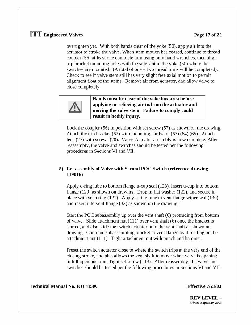
overtighten yet. With both hands clear of the yoke (50), apply air into theactuator to stroke the valve. When stem motion has ceased, continue to threadcoupler (56) at least one complete turn using only hand wrenches, then aligntrip bracket mounting holes with the side slot in the yoke (50) where theswitches are mounted. (A total of one – two thread turns will be completed). Check to see if valve stem still has very slight free axial motion to permitalignment float of the stems. Remove air from actuator, and allow valve toclose completely.
Hands must be clear of the yoke box area beforeapplying or relieving air to/from the actuator andmoving the valve stem. Failure to comply couldresult in bodily injury.
Lock the coupler (56) in position with set screw (57) as shown on the drawing.Attach the trip bracket (62) with mounting hardware (63) (64) (65). Attachlens (77) with screws (78). Valve-Actuator assembly is now complete. Afterreassembly, the valve and switches should be tested per the followingprocedures in Sections VI and VII.
5) Re -assembly of Valve with Second POC Switch (reference drawing119016)
Apply o-ring lube to bottom flange u-cup seal (123), insert u-cup into bottomflange (120) as shown on drawing. Drop in flat washer (122), and secure inplace with snap ring (121). Apply o-ring lube to vent flange wiper seal (130),and insert into vent flange (32) as shown on the drawing.
Start the POC subassembly up over the vent shaft (6) protruding from bottomof valve. Slide attachment nut (111) over vent shaft (6) once the bracket isstarted, and also slide the switch actuator onto the vent shaft as shown ondrawing. Continue subassembling bracket to vent flange by threading on theattachment nut (111). Tight attachment nut with punch and hammer.
Preset the switch actuator close to where the switch trips at the very end of theclosing stroke, and also allows the vent shaft to move when valve is openingto full open position. Tight set screw (113). After reassembly, the valve andswitches should be tested per the following procedures in Sections VI and VII.

ITT Engineered Valves Page 18 of 22
Technical Manual No. IOT4150C Effective 7/21/03
REV LEVEL –Printed August 29, 2003
C. Valve Maintenance
Periodic Inspection
þ Periodic leak testing of both block valves and verification of proper operationof proof of closure switch is recommended per the time schedule in theapplicable codes. See Section VI for leak testing and Section VII for switchsetting techniques.
þ Inspect solenoid and actuator breather vents for foreign debri that can clog thebreathing surfaces. Clean thoroughly or replace as required.
þ Check for proper position and adhesion of the visual indicator label, andcaution labels.
þ Inspect switch trip brackets for straightness, that they are not bent, giving falsereadings.
þ Ensure that the clear lens is attached. Re-install if missing.
þ “Snoop” all sealing joints to make sure there are no external valve leaks.
þ Check actuator supply air line for proper pressure settings (60 –120 psig)
þ Check condition of all wiring/conduit and fittings for electrical components.
Preventative Maintenance
Valve soft seals should be replaced every 4 – 5 years UNLESS regular leak testinspections indicate earlier need. See Section VI for leak testing. See Section IXfor information on ordering replacement parts for your Skotch Safety Shut-off Gasvalve.

ITT Engineered Valves Page 19 of 22
Technical Manual No. IOT4150C Effective 7/21/03
REV LEVEL –Printed August 29, 2003
VI. LEAK TESTING
It is necessary to leak test each block valve and the vent valve individually to properlyqualify the status of each seal. The valves are named in accordance to their position andfunction within the valve system.
A. Inlet Valve
1. Verify the valve is in the closed position.
2. Seal the outlet of the valve.
3. Pressurize inlet with 60 psig clean dry air while monitoring leak rate fromthe vent port. FM specifies a leak rate of 1 ft3/hr or less.
B. Outlet Valve
4. Verify the valve is in the closed position.
5. Seal the inlet side of the valve.
6. Pressurize the vent with 60 psig clean dry air while monitoring leak ratefrom the outlet. FM specifies a leak rate of 1 ft3/hr or less.
C. Vent Valve
1. Verify the valve is in the open position.
2. Seal the outlet port.
3. Pressurize the inlet with a maximum of 60 psig clean dry air, whilemonitoring the leak rate from the vent port. FM specifies a leak rate of 1ft3/hr or less.
ITT Engineered Valves Page 20 of 22
Technical Manual No. IOT4150C Effective 7/21/03
REV LEVEL –Printed August 29, 2003
VII. PROOF OF CLOSURE SWITCH TESTING
The T4150C valve system is provided with one proof of closure switch as standard. It canbe provided with an optional open switch. The valves can also be provided with a second(inlet block) POC switch as well. Check the order specification for configurationprovided.
The intent of the POC switch is to trip during valve seal overtravel of the valve block.Valve seal overtravel is the additional travel the valve strokes after flow stops. Forreference FM defines the point of valve closure when flow < 1 ft3/hr. The switchesshould only change contact state when there is no flow. For example: When going fromopen to close, gas flow should stop and then the POC switch trip. Conversely, whengoing from closed to open the POC switch should change contact states prior to flowstarting.
The POC switches should be tested after the valve has been leak tested.
1. Testing
a) Verify the valve is in the closed position and the normally closedcontacts are made.
b) Plug the inlet port. Stroke the valve very slowly until the switchtrips. At this point, stop movement of the actuator and verify flowhas not commenced (< 1 ft3/hr) by pressurizing the vent port to 50psig and measuring flow at the outlet. The actuator can be strokedslowly by regulating air pressure to the actuator.
c) If there is evidence of flow prior to the POC switch tripping, thePOC switch needs to be adjusted.
2. Setting
a) Loosen the roller switch lever (Item 67 or 102).
b) Place an 0.100" shim between the switch actuator (Item 62 or 112)and the roller switch lever.

ITT Engineered Valves Page 21 of 22
Technical Manual No. IOT4150C Effective 7/21/03
REV LEVEL –Printed August 29, 2003
c) While holding the roller firmly against the actuator shaft, rotate theswitch actuator shaft until the normally closed contacts of theswitch break. At this point securely fasten the lever to the switchactuator shaft.
d) Remove the spacer. The roller switch lever should be firmly restingon the switch shaft and the normally closed contacts made.
e) Check switch setting by stroking the valve to the open position.Pressurize the vent with 50 psig and monitor the flow at the outletvalve. If the switch trips before flow ceases, repeat but decreaseshim thickness by 1/32". If the switch does not reset, increase theshim thickness by 1/32".
VIII. MISCELLANEOUS INSTRUCTIONS FOR SPECIAL OPTIONS
Due to customer requirements, some T4150C Systems incorporate special options. Anyspecial procedures not covered in the above material can be found in the ReferenceSection of this manual as addenda.
ITT Engineered Valves Page 22 of 22
Technical Manual No. IOT4150C Effective 7/21/03
REV LEVEL –Printed August 29, 2003
IX. SPARE PARTS ORDERING INFORMATION
Orders for T4150C Valve Systems Spare Parts, rebuild kits, and tools should be placedwith:
ITT IndustriesEngineered Process Solutions Group33 Centerville RoadLancaster, PA 17603-2064
Phone: 717-509-2200Fax: 800-348-9000
Please be advised that such items as solenoids and switches should not be ordered directlyfrom their manufacturers as materials may be specially designed for Skotch TrifectaSystem service. Other replacement parts, although they may be similar in function, willvoid the FM rating. To ensure FM rating and/or proper operation, replacementcomponents should be purchased through ITT Engineered Process Solutions Group.
X. REFERENCE INFORMATION
The following pages contain drawings and reference information alluded to in abovesections.
Printed 08-29-03 02:18:49 PM


Printed 02-24-05 12:39:18 PM
Printed 02-24-05 12:37:40 PM