Embed Size (px)
Citation preview

A DIVISION OF
456 Creamery Way, Exton, PA 19341 Phone: 610.524.8800 • Fax: 610.524.8807 • Email: [email protected]
www.neutronicsinc.com
High Purity Instruments
MODEL 4-SPM-N1-SS Remote Oxygen Sensor Module and Sampling System with Internal Pump – for Model 4100 PERCENT to PPB RANGE
Oxygen Analyzer
OPERATION MANUAL
Manual Part Number: C5-06-4900-21-0 Revision Level: B -ECO 8151 Document Number: MN-A-0116 Revision Date: March 13, 2007
Engineered Solutions for Gas Detection and Analysis

Installation and Operations Manual
Manual Part Number: C5-06-4900-21-0
Document Number: MN-A-0116 Rev.B
Revision Date: March 13, 2007
Page iii
Table of Contents TABLE OF CONTENTS ...........................................................................................................................................................III FOR YOUR SAFETY: ............................................................................................................................................................... V WELCOME ............................................................................................................................................................................. VI CHAPTER 1 – INTRODUCTION AND OVERVIEW............................................................................................................... 1-1
1.1 GENERAL ...................................................................................................................................................................1-1 1.2 FEATURES ..................................................................................................................................................................1-2 1.3 SYSTEM COMPONENTS ................................................................................................................................................1-3
1.3.1 Oxygen Sensor ............................................................................................................................ 1-4 1.3.2 Sensor Heater .............................................................................................................................. 1-4 1.3.3 Heater Modulator ....................................................................................................................... 1-4 1.3.4 Heater Control Board ................................................................................................................. 1-4 1.3.5 VAC Select Switch ....................................................................................................................... 1-5 1.3.6 Chassis ........................................................................................................................................ 1-5
1.4 OXYGEN SAMPLING COMPONENTS ...............................................................................................................................1-5 1.4.1 Sample Pump .............................................................................................................................. 1-5 1.4.2 Flow Orifice................................................................................................................................. 1-5 1.4.3 Bypass Stream Check-Valve....................................................................................................... 1-6
1.5 INPUTS AND OUTPUTS.................................................................................................................................................1-6 1.5.1 Sample Inlet Port........................................................................................................................ 1-6 1.5.2 Sample Exhaust Port.................................................................................................................. 1-6 1.5.3 Bypass Exhaust Port .................................................................................................................. 1-6 1.5.4 Model 4100 Analyzer Interface ................................................................................................. 1-6 1.5.5 VAC Electrical Power Plug......................................................................................................... 1-7
CHAPTER 2 – SYSTEM INSTALLATION AND START-UP................................................................................................. 2-1 2.1 STEP 1 – LOCATE THE RSM ........................................................................................................................................2-2 2.2 STEP 2 – INSTALL THE MODEL 4100 ANALYZER...........................................................................................................2-3 2.3 STEP 3 – INSTALL THE MODEL 4-SPM-N1-SS...........................................................................................................2-3
2.3.1 Sample Inlet Port........................................................................................................................ 2-4 2.3.2 Sample Exhaust Port.................................................................................................................. 2-4 2.3.3 Bypass Exhaust Port .................................................................................................................. 2-5 2.3.4 Model 4100 Analyzer Interface ................................................................................................. 2-5 2.3.5 VAC Electrical Power Plug......................................................................................................... 2-5
2.4 STEP 4 – POWER UP THE MODEL 4100 AND RSM.........................................................................................................2-5 CHAPTER 3 – SYSTEM OPERATION .................................................................................................................................. 3-1
3.1 MODES OF OPERATION OVERVIEW................................................................................................................................3-1 3.2 ONLINE SAMPLING MODE ...........................................................................................................................................3-1 3.3 CALIBRATION SAMPLING MODE ...................................................................................................................................3-1
3.3.1 Remove the RSM from Online Service ....................................................................................... 3-2 3.3.2 Apply Calibration Gas to the RSM ............................................................................................ 3-2 3.3.3 Return the RSM to Online Service.............................................................................................. 3-2
Installation and Operations Manual
Manual Part Number: C5-06-4900-21-0
Document Number: MN-A-0116 Rev. B
Revision Date: March 13, 2007 Page iv
CHAPTER 4 – MAINTENANCE AND TROUBLESHOOTING............................................................................................... 4-1 4.1 ROUTINE PERIODIC MAINTENANCE...............................................................................................................................4-1
4.1.1 Calibrate Sensor ......................................................................................................................... 4-1 4.1.2 Clean the RSM Chassis ............................................................................................................... 4-1 4.1.3 Sensor Clean................................................................................................................................ 4-2 4.1.4 Replace Oxygen Sensor............................................................................................................... 4-2
4.2 TROUBLESHOOTING.....................................................................................................................................................4-3 4.2.1 Fault Codes.................................................................................................................................. 4-3 4.2.2 Troubleshooting Common Problems with the RSM ................................................................. 4-4 4.2.3 Problem 2 – Display reads too low ............................................................................................ 4-5 4.2.4 Problem 3 – Erratic or intermittent display ............................................................................ 4-5
CHAPTER 5 – APPENDICES............................................................................................................................................... 5-1 5.1 APPENDIX A – SPARE PARTS LIST...............................................................................................................................5-1 5.2 APPENDIX B - SPECIFICATIONS....................................................................................................................................5-2 5.3 APPENDIX C – MATERIAL SAFETY DATA SHEET ............................................................................................................5-3 5.4 APPENDIX D – WARRANTY ..........................................................................................................................................5-4
INTENDED USE FOR THE MODEL 4-SPM-N1-SS............................................................................................................ 5-4

Installation and Operations Manual
Manual Part Number: C5-06-4900-21-0
Document Number: MN-A-0116 Rev.B
Revision Date: March 13, 2007
Page v
For Your Safety: PLEASE READ THIS MANUAL IN ITS ENTIRETY BEFORE ATTEMPTING INSTALLATION OR OPERATION! Attempting to operate the Model 4-SPM-N1-SS without fully understanding its features and functions may result in unsafe conditions
• Always use protective eye wear and observe proper safety procedures when working with pressurized gases.
• Always assure the pressure of gas entering the remote sensor unit is compatible with the operating instruction. Do not exceed 5 PSIG.
• Always calibrate the Model 4-SPM-N1-SS at an equivalent pressure and flow rate to the measured gas.
• Always allow the Model 4-SPM-N1-SS remote sensor to cool down before attempting to access the sensor.
• Never expose the remote sensor module chassis to water, high humidity or moisture. The remote sensor module chassis is not watertight.
• Never expose the model 4-SPM-N1-SS to flame or high temperatures.
• Never expose the model 4-SPM-N1-SS remote sensor module directly to unregulated gas lines, cylinder gas. High gas pressures may cause a failure in the sampling system.
• Ensure the analyzer unit is mounted in an area of free airflow to prevent the chassis from exceeding the operating temperature specifications. Do not mount the sensor against hot surfaces. Do not block the ventilation louvers on the remote sensor chassis.
• Make certain to set the model 4100 analyzer and model 4-SPM-N1-SS remote sensor module to the proper operating voltage: 110 or 220 VAC. This must be set before operation of the remote sensor module. Failure to properly set the operating power may result in damaging the sensor assembly. Refer to the model 4100 oxygen analyzer equipment manual.
Installation and Operations Manual
Manual Part Number: C5-06-4900-21-0
Document Number: MN-A-0116 Rev. B
Revision Date: March 13, 2007 Page vi
WELCOME
Thank you for purchasing the Model 4-SPM-N1-SS Remote Sensor Module for the Model 4100 Oxygen Analyzer. The Model 4-SPM-N1-SS Remote Sensor Module is the oxygen sensing apparatus for the model 4100 compact series Oxygen Analyzer by Neutronics Inc. It is designed for easy installation, operation and maintenance, all of which will be described in this manual. We recommend that all personnel who use Remote Sensor Module read this manual to become more familiar with its proper operation.
For further detail regarding the maintenance and in-field service of the Model 4-SPM-N1-SS Remote Sensor Module, please contact the Neutronics Inc. Customer Service Department. If you have questions or comments, we would like to hear from you.
Neutronics Inc. Customer Service Department 456 Creamery Way Exton, PA 19341 Tel: (610) 524-8800 ext 118 Toll Free: (800) 378-2287 ext 118 (US only) Fax: (610) 524-8807
EMAIL: [email protected] Visit us at www.neutronicsinc.com
Equipment Serial Number: ________________ (For faster service, please have this number ready if for any reason you need to contact us about your instrument)
Copyright ©2003 Neutronics Inc.
This work is protected under Title 17 of the US Code and is the sole property of Neutronics Inc. No part of this document may be copied or otherwise reproduced, or stored in any electronic information retrieval system, except as specifically permitted under US copyright law, without the prior written consent of Neutronics Inc.
Manual Part Number: C5-06-4900-21-0
Document Number: MN-A-0116 Rev. B
Revision Date: March 13, 2007 Page 1-1
1 CHAPTER 1 – INTRODUCTION AND OVERVIEW
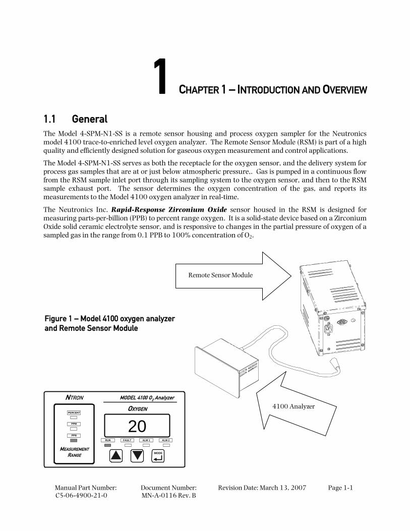
1.1 General The Model 4-SPM-N1-SS is a remote sensor housing and process oxygen sampler for the Neutronics model 4100 trace-to-enriched level oxygen analyzer. The Remote Sensor Module (RSM) is part of a high quality and efficiently designed solution for gaseous oxygen measurement and control applications.
The Model 4-SPM-N1-SS serves as both the receptacle for the oxygen sensor, and the delivery system for process gas samples that are at or just below atmospheric pressure,. Gas is pumped in a continuous flow from the RSM sample inlet port through its sampling system to the oxygen sensor, and then to the RSM sample exhaust port. The sensor determines the oxygen concentration of the gas, and reports its measurements to the Model 4100 oxygen analyzer in real-time.
The Neutronics Inc. Rapid-Response Zirconium Oxide sensor housed in the RSM is designed for measuring parts-per-billion (PPB) to percent range oxygen. It is a solid-state device based on a Zirconium Oxide solid ceramic electrolyte sensor, and is responsive to changes in the partial pressure of oxygen of a sampled gas in the range from 0.1 PPB to 100% concentration of O2.
MEASUREMENT
RANGEMODE
RUN FAULT ALM 1 ALM 2
20OXYGEN
MODEL 4100 O2 AnalyzerNTRON
PERCENT
PPM
PPB
Figure 1 – Model 4100 oxygen analyzer and Remote Sensor Module
Remote Sensor Module
4100 Analyzer
Model 4-SPM-N1-SS – Introduction and Overview
Manual Part Number: C5-06-4900-21-0
Document Number: MN-A-0116 Rev. B
Revision Date: March 13, 2007 Page 1-2
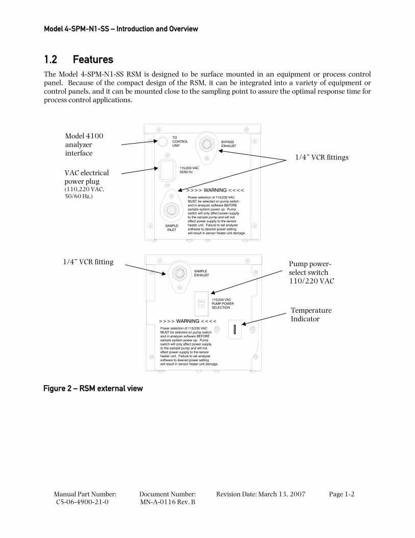
1.2 Features The Model 4-SPM-N1-SS RSM is designed to be surface mounted in an equipment or process control panel. Because of the compact design of the RSM, it can be integrated into a variety of equipment or control panels, and it can be mounted close to the sampling point to assure the optimal response time for process control applications.
will result in sensor heater unit damage.software to desired power settingheater unit. Failure to set analyzer
>>>> WARNING <<<<Power selection of 115/230 VAC MUST be selected on pump switchand in analyzer software BEFOREsample system power up. Pump switch will only affect power supplyto the sample pump and will notaffect power supply to the sensor
PUMP POWER115/230 VAC
SELECTION
EXHAUSTSAMPLE
SAMPLEINLET
to the sample pump and will notswitch will only affect power supply
and in analyzer software BEFOREMUST be selected on pump switchPower selection of 115/230 VAC
sample system power up. Pump
affect power supply to the sensorheater unit. Failure to set analyzer
will result in sensor heater unit damage.software to desired power setting
50/60 Hz115/230 VAC
>>>> WARNING <<<<
CONTROLUNIT
TOBYPASSEXHAUST
Figure 2 – RSM external view
Model 4100 analyzer interface
VAC electrical power plug (110,220 VAC, 50/60 Hz.)
1/4” VCR fittings
1/4” VCR fitting Pump power- select switch 110/220 VAC
Temperature Indicator
System Components
Manual Part Number: C5-06-4900-21-0
Document Number: MN-A-0116 Rev.B
Revision Date: March 13, 2007
Page 1-3
Other Features Include:
• Ultra-fast response time
• Not position or motion sensitive
• Not affected by Oxygen Shock: measures from air to PPB in minutes
• Small compact packaging
• Top or bottom mounting
• 316 SS wetted materials of construction
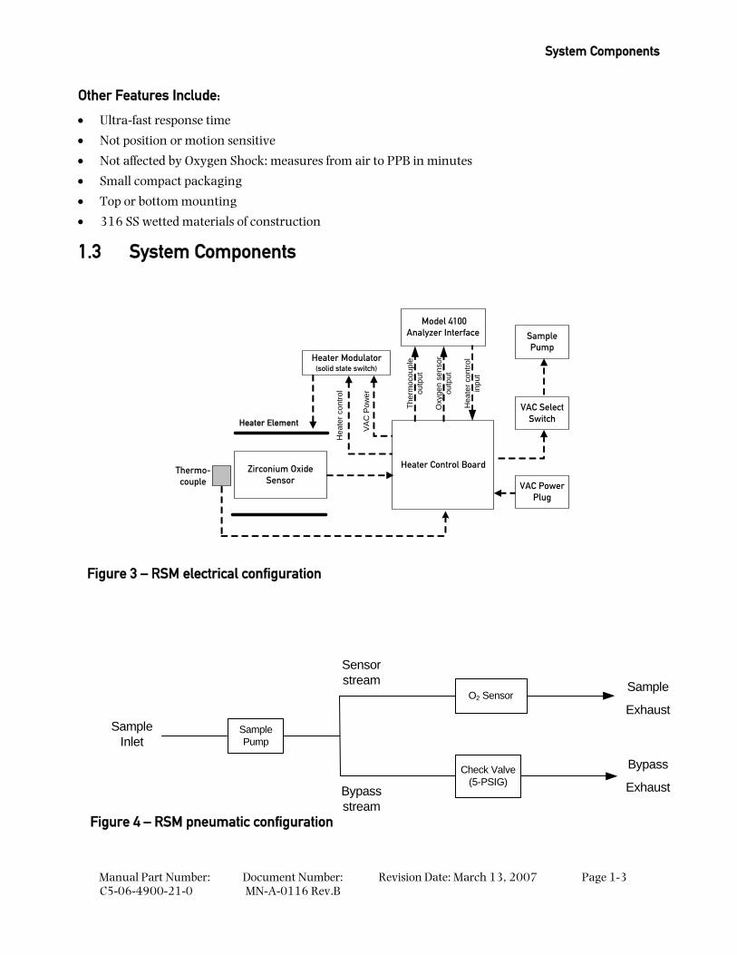
1.3 System Components
Zirconium OxideSensor
Heater Element
Heater Modulator(solid state switch)
Heater Control Board
Ther
moc
oupl
eou
tput
Model 4100Analyzer Interface
VAC PowerPlug
Thermo-couple
Oxy
gen
sens
orou
tput
Hea
ter c
ontro
lin
put
Hea
ter c
ontro
l
VAC
Pow
er
VAC SelectSwitch
SamplePump
Sample Inlet
O2 SensorSample
Exhaust
Check Valve(5-PSIG)
Sensor stream
Bypass stream
Sample Pump
Bypass
Exhaust
Figure 3 – RSM electrical configuration
Figure 4 – RSM pneumatic configuration
Model 4-SPM-N1-SS – Introduction and Overview
Manual Part Number: C5-06-4900-21-0
Document Number: MN-A-0116 Rev. B
Revision Date: March 13, 2007 Page 1-4
1.3.1 Oxygen Sensor The Neutronics Inc. rapid-response zirconium oxide sensor is a solid-state ceramic device. When heated by its unique furnace, it produces a predictable electrical output in response to changes in the partial pressure of oxygen of a sampled gas in the range from 0.1 PPB to 100% concentration of oxygen. The most notable advantage of the ceramic sensor technology is its ability to rapidly measure oxygen through large step changes in concentration. For example, the zirconium oxide sensor can accurately measure PPM concentrations of oxygen within seconds after exposure to air.
The sensor is constructed of a specially formulated porous zirconium oxide electrolyte tube. The tube surface is coated on the inside and outside, each with a layer of porous platinum. Each coated surface serves as an electrode – one as a cathode, the other as an anode. A unique heater assembly and thermocouple probe provide a controlled temperature environment for sensor operation.
At a temperature of 6500C, openings within the ceramic tube lattice allow oxygen ions to pass. If the partial pressure of oxygen is equal on both sides of the ceramic lattice, then there is no net flow of ions between the electrodes (i.e.: the sample gas and reference gas are both air). However, when the partial pressure of oxygen of the sample gas is different from the reference gas, there is predictable ionic transfer.
At operational temperature, oxygen is electrochemically reduced at the cathode. Oxygen ions migrate through the ceramic electrolyte and are electrochemically oxidized at the anode. Thus, an equal amount of oxygen is produced at the anode at the same time oxygen is reduced at the cathode. The voltage produced is proportional to the net difference in the partial pressures of oxygen in the reference gas (air at 20.9% oxygen) verses the sampled gas.
1.3.2 Sensor Heater The sensor heater maintains the temperature of the oxygen sensor at 650° C for proper operation. The sensor heater is housed within an aluminum chassis, filled with insulating material to prevent heat loss. The heater assembly includes a thermocouple (section 1.5.4.2). The Model 4100 analyzer uses the thermocouple output to generate the heater control input to the RSM (section 1.5.4.3) for regulating the sensor heater’s operating temperature. The sensor heater requires a modulated 110/220 VAC, 50/60 Hz power source. A thermal cutout switch is included, to prevent over-temperatures from damaging the assembly.
1.3.3 Heater Modulator The heater modulator is a high-speed solid-state switch mounted on the heater control board (section 1.3.4) that provides precision control of the sensor heater temperature by modulating its VAC electrical power input continuously. Its duty-cycle is determined by the frequency of the heater control input from the model 4100 analyzer.
1.3.4 Heater Control Board The heater control board serves as the main interface between the RSM, and the model 4100 analyzer (figure 3). It houses the model 4100 analyzer interface port (section 1.5.4) and the VAC electrical power plug for the RSM (section 1.5.5). The oxygen sensor output, the heater thermocouple output and the heater control input are all interfaced with the model 4100 analyzer through the heater control board. In addition, it houses the heater modulator.
Oxygen Sampling Components
Manual Part Number: C5-06-4900-21-0
Document Number: MN-A-0116 Rev.B
Revision Date: March 13, 2007
Page 1-5
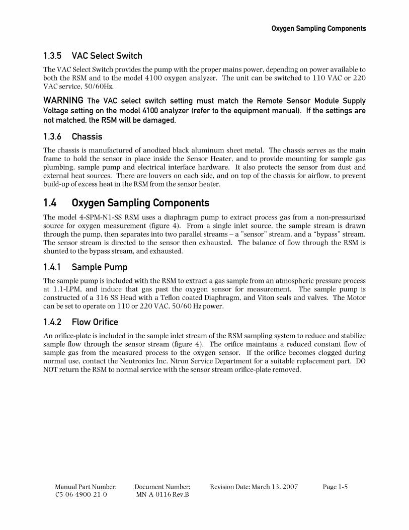
1.3.5 VAC Select Switch The VAC Select Switch provides the pump with the proper mains power, depending on power available to both the RSM and to the model 4100 oxygen analyzer. The unit can be switched to 110 VAC or 220 VAC service, 50/60Hz.
WARNING The VAC select switch setting must match the Remote Sensor Module Supply Voltage setting on the model 4100 analyzer (refer to the equipment manual). If the settings are not matched, the RSM will be damaged.
1.3.6 Chassis The chassis is manufactured of anodized black aluminum sheet metal. The chassis serves as the main frame to hold the sensor in place inside the Sensor Heater, and to provide mounting for sample gas plumbing, sample pump and electrical interface hardware. It also protects the sensor from dust and external heat sources. There are louvers on each side, and on top of the chassis for airflow, to prevent build-up of excess heat in the RSM from the sensor heater.
1.4 Oxygen Sampling Components The model 4-SPM-N1-SS RSM uses a diaphragm pump to extract process gas from a non-pressurized source for oxygen measurement (figure 4). From a single inlet source, the sample stream is drawn through the pump, then separates into two parallel streams – a ”sensor” stream, and a “bypass” stream. The sensor stream is directed to the sensor then exhausted. The balance of flow through the RSM is shunted to the bypass stream, and exhausted.
1.4.1 Sample Pump The sample pump is included with the RSM to extract a gas sample from an atmospheric pressure process at 1.1-LPM, and induce that gas past the oxygen sensor for measurement. The sample pump is constructed of a 316 SS Head with a Teflon coated Diaphragm, and Viton seals and valves. The Motor can be set to operate on 110 or 220 VAC, 50/60 Hz power.
1.4.2 Flow Orifice An orifice-plate is included in the sample inlet stream of the RSM sampling system to reduce and stabilize sample flow through the sensor stream (figure 4). The orifice maintains a reduced constant flow of sample gas from the measured process to the oxygen sensor. If the orifice becomes clogged during normal use, contact the Neutronics Inc. Ntron Service Department for a suitable replacement part. DO NOT return the RSM to normal service with the sensor stream orifice-plate removed.
Model 4-SPM-N1-SS – Introduction and Overview
Manual Part Number: C5-06-4900-21-0
Document Number: MN-A-0116 Rev. B
Revision Date: March 13, 2007 Page 1-6
1.4.3 Bypass Stream Check-Valve A Check-Valve designed to open at 5-PSIG of pressure is included in the RSM sampling system (figure 4). If the sampled source pressure exceeds 5-PSIG, the surplus sample gas will be shunted around the sensor stream. This will help to maintain a stable sample flow to the oxygen sensor and to protect it from over-pressure conditions.
1.5 Inputs and Outputs
1.5.1 Sample Inlet Port The Sample Inlet Port is a 1/4” VCR bulkhead fitting in the RSM chassis for pneumatic interfacing with the measured process. It is the single sample gas inlet to the RSM.
1.5.2 Sample Exhaust Port The Sample Exhaust Port is a 1/4” VCR bulkhead fitting in the RSM chassis. It is the low volume sample exhaust line, supplied by the flow-controlled sensor stream in the RSM. It should be connected to a suitable vent location.
1.5.3 Bypass Exhaust Port The Bypass Exhaust Port is a 1/4” VCR bulkhead fitting in the RSM chassis. It is the high volume sample exhaust line, supplied by the bypass stream in the RSM. It should be connected to a suitable vent location.
1.5.4 Model 4100 Analyzer Interface The Model 4100 Analyzer Interface is a single 8-pin DIN connection that connects the RSM electrically to the Model 4100 analyzer. It includes the oxygen sensor output, the sensor heater thermocouple output, and the sensor heater control Input. An interface cable is included with the model 4100/RSM system.
1.5.4.1 The Oxygen Sensor Output
The Oxygen Sensor Output is used by the model 4100 analyzer to indicate the oxygen concentration in the measured process. It is proportional to the sampled Oxygen present in the process gas stream or vessel headspace.
1.5.4.2 Sensor Heater Thermocouple Output
The thermocouple included on the heater assembly feeds back a voltage potential to the model 4100 analyzer proportional to the sensor heater temperature through the Sensor Heater Thermocouple Output. The Model 4100 uses that electrical output to control the sensor heater temperature.
Inputs and Outputs
Manual Part Number: C5-06-4900-21-0
Document Number: MN-A-0116 Rev.B
Revision Date: March 13, 2007
Page 1-7
1.5.4.3 Sensor Heater Control Input
The Model 4100 generates a variable frequency control signal to the RSM Sensor Heater Control Input for the heater modulator, based on the RSM Sensor Thermocouple Output. The heater control input from the model 4100 analyzer determines the duty-cycle of the heater modulator to keep the sensor heater at 650°C, by changing its average VAC input power. This method provides continuous control of the sensor heater temperature, within the limited control range necessary to operate the solid-state oxygen sensor.
1.5.5 VAC Electrical Power Plug The Model 4-SPM-N1-SS requires VAC electrical power. The VAC Electrical Power Plug is a standard 3-prong grounded male connector (IEC connector).

Manual Part Number: C5-06-4900-21-0
Document Number: MN-A-0116 Rev. B
Revision Date: March 13, 2007 Page 2-1
2 CHAPTER 2 – SYSTEM INSTALLATION AND START-UP
STEP 2:INSTALL THE MODEL 4100
ANALYZER
STEP 3:INSTALL THE RSM
STEP 4:POWER UP…
Model 4100 and RSM
STEP 1:LOCATE THE RSM
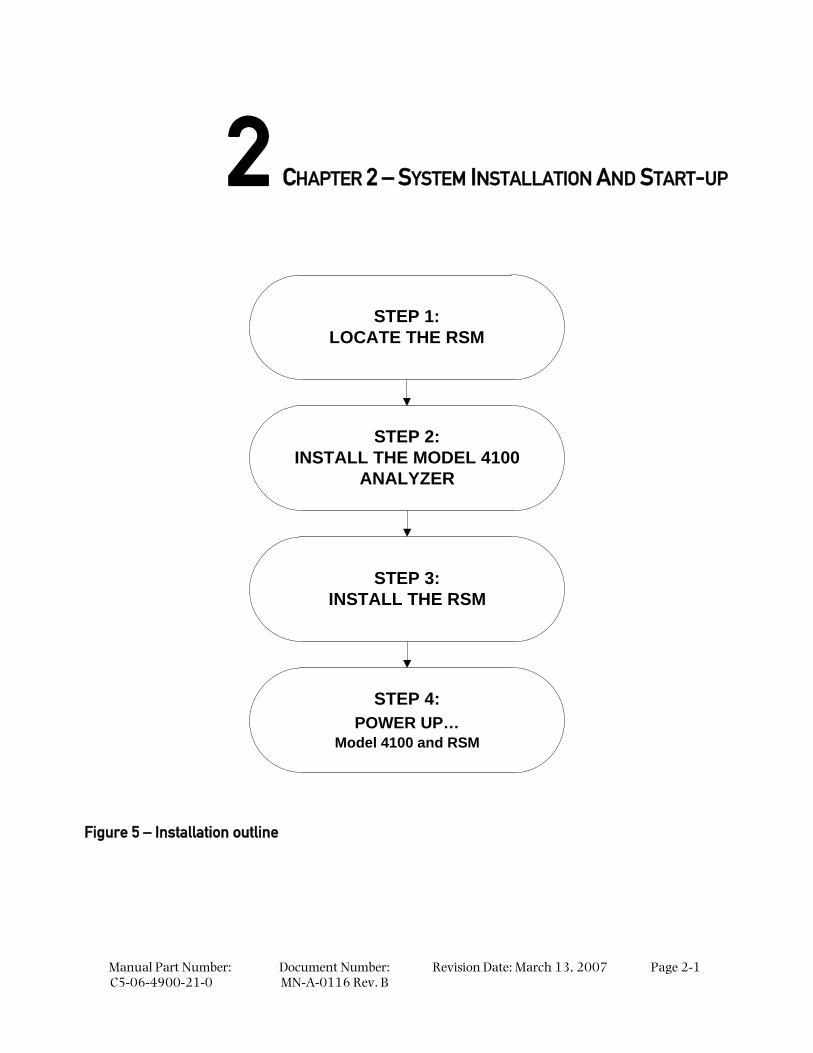
Figure 5 – Installation outline
System Installation and Start-up
Manual Part Number: C5-06-4900-21-0
Document Number: MN-A-0116 Rev. B
Revision Date: March 13, 2007 Page 2-2
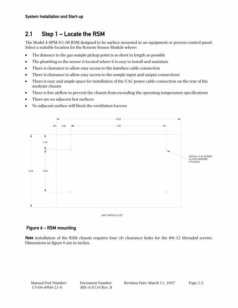
2.1 Step 1 – Locate the RSM The Model 4-SPM-N1-SS RSM designed to be surface mounted in an equipment or process control panel. Select a suitable location for the Remote Sensor Module where:
• The distance to the gas sample pickup point is as short in length as possible
• The plumbing to the sensor is located where it is easy to install and maintain
• There is clearance to allow easy access to the interface cable connection
• There is clearance to allow easy access to the sample input and output connections
• There is easy and ample space for installation of the VAC power cable connection on the rear of the analyzer chassis
• There is free airflow to prevent the chassis from exceeding the operating temperature specifications
• There are no adjacent hot surfaces
• No adjacent surface will block the ventilation louvers
INSTALL 8-32 SCREW& LOCK WASHER4 PLACES
UNIT HEIGHT 6.125"
6.24 4.00
9.20
1.12
7.201.00
Figure 6 – RSM mounting
Note installation of the RSM chassis requires four (4) clearance holes for the #8-32 threaded screws. Dimensions in figure 6 are in inches.
Install the Model 4-SPM-N1-SS
Manual Part Number: C5-06-4900-21-0
Document Number: MN-A-0116 Rev.B
Revision Date: March 13, 2007
Page 2-3
2.2 Step 2 – Install the Model 4100 Analyzer For detailed instructions on model 4100 oxygen Analyzer installation, please refer to the equipment manual.
2.3 Step 3 – Install the Model 4-SPM-N1-SS
CAUTION: Remember to verify / set the model 4100 analyzer software and RSM hardware switch to the proper operating voltage (section 4.1.2.17) – 110 or 220 VAC. This must be set before operation of the remote sensor module. Failure to properly set the operating power will result in damage to the RSM components.
DANGER: Electrical connections on the rear of the Model 4100 oxygen analyzer or at the RSM may have hazardous voltages present once power has been applied to the unit. High voltages may remain for a short time even after power has been disconnected from the two units. Take care in observing standard electrical practices when making electrical connections to the Model 4100 oxygen analyzer and RSM.
DANGER: The model 4-SPM-N1-SS RSM is not rated intrinsically safe or explosion proof. Be certain that no flammable and toxic gases are present in the area where the RSM will be installed.
CAUTION: The model 4-SPM-N1-SS chassis is not rated waterproof. Do not mount the RSM in an area where it may contact water or other liquid elements.
WARNING: Be certain that all power is OFF to the analyzer and associated wiring (cables) before attempting installation. DO NOT WORK WITH LIVE WIRES! Do not leave any exposed wire at the terminal blocks. Before applying power, ensure terminal blocks are fully inserted into the mating connector at the analyzer.
CAUTION: Be certain to regulate the supplied gas pressure to the 4-SPM-N1-SS sample inlet port. Never connect an unregulated gas supply to the RSM. Maximum allowable pressure: 7-PSIG.
CAUTION: Always start up the model 4-SPM-N1-SS under atmospheric pressure. Do not apply pressure from the sampled source before starting up the RSM. Starting up the sample pump under positive pressure will damage the unit.
CAUTION: Do not allow the 4-SPM-N1-SS to sample Hydrogen, Carbon Monoxide, Hydrocarbon, or Halogenated gases while in service. Do not mount the 4-SPM-N1-SS in an area where Carbon Monoxide, Hydrogen, Hydrocarbon, or Halogenated gases may be present around the unit while in service. If the oxygen sensor is exposed to any of these gases, system accuracy will be affected.
The model 4-SPM-N1-SS must be mounted in an area where there is free air flow, providing a constant source of ambient air around the unit, containing 20.9% oxygen. Higher or lower levels of oxygen concentration in the atmosphere around the RSM will affect system accuracy.
System Installation and Start-up
Manual Part Number: C5-06-4900-21-0
Document Number: MN-A-0116 Rev. B
Revision Date: March 13, 2007 Page 2-4
2.3.1 Sample Inlet Port Pneumatic connection to the measured process for sample extraction is made at the 1/4” VCR bulkhead fitting on the RSM chassis, labelled “Sample Inlet”. For connecting the RSM to the measured process, use 316-stainless steel tubing, and 1/4” VCR high purity fittings. Ensure that no grease, particulate, or solvent is present in the tubing during installation. Match the sample inlet tubing connection against the ID label on the RSM chassis. Fix all sample tubing and connectors.
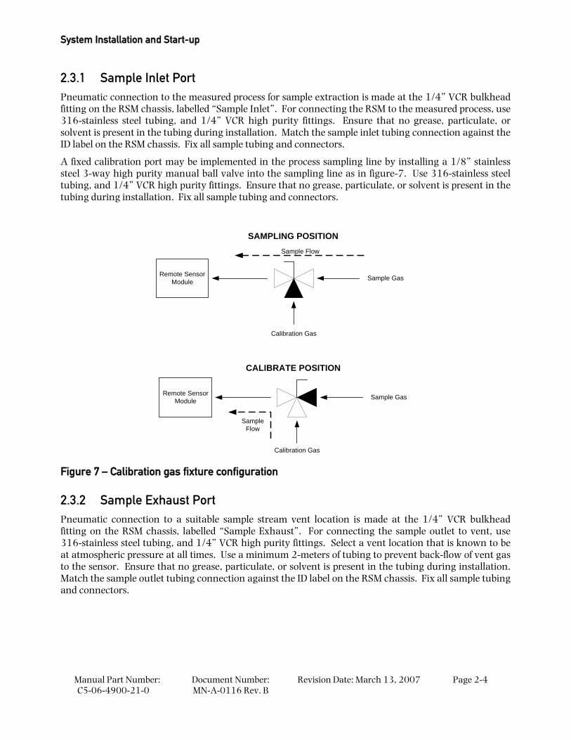
A fixed calibration port may be implemented in the process sampling line by installing a 1/8” stainless steel 3-way high purity manual ball valve into the sampling line as in figure-7. Use 316-stainless steel tubing, and 1/4” VCR high purity fittings. Ensure that no grease, particulate, or solvent is present in the tubing during installation. Fix all sample tubing and connectors.
Remote SensorModule
Calibration Gas
Sample Gas
Sample Flow
Remote SensorModule
Calibration Gas
Sample Gas
SampleFlow
SAMPLING POSITION
CALIBRATE POSITION
Figure 7 – Calibration gas fixture configuration
2.3.2 Sample Exhaust Port Pneumatic connection to a suitable sample stream vent location is made at the 1/4” VCR bulkhead fitting on the RSM chassis, labelled “Sample Exhaust”. For connecting the sample outlet to vent, use 316-stainless steel tubing, and 1/4” VCR high purity fittings. Select a vent location that is known to be at atmospheric pressure at all times. Use a minimum 2-meters of tubing to prevent back-flow of vent gas to the sensor. Ensure that no grease, particulate, or solvent is present in the tubing during installation. Match the sample outlet tubing connection against the ID label on the RSM chassis. Fix all sample tubing and connectors.
Power up the Model 4100 & RSM
Manual Part Number: C5-06-4900-21-0
Document Number: MN-A-0116 Rev.B
Revision Date: March 13, 2007
Page 2-5
2.3.3 Bypass Exhaust Port Pneumatic connection to a suitable bypass stream vent location is made at the 1/4” VCR bulkhead fitting on the rear of the RSM chassis, labelled “Bypass Exhaust”. To connect the sample bypass exhaust to vent, use 316-stainless steel tubing, and 1/4” VCR high purity fittings. Select a vent location that is known to be at atmospheric pressure at all times. Use a minimum 2-meters of tubing to prevent back-flow of vent gas to the sensor. Ensure that no grease, particulate, or solvent is present in the tubing during installation. Match the sample outlet tubing connection against the ID label on the RSM chassis. Fix all sample tubing and connectors.
2.3.4 Model 4100 Analyzer Interface Electrical connection to the model 4100 oxygen analyzer is made at the female 8-pin DIN connector on the rear of the RSM chassis, labelled “To Control Unit”. To connect the two units, use the interface cable supplied with the 4100-analyzer/RSM system. Match the cable connector against the ID label on the RSM chassis. Fix all wiring and connectors.
2.3.5 VAC Electrical Power Plug Electrical connections for VAC power are made at VAC Power Plug on the rear of the RSM chassis, labelled “Power Cord”. To connect mains power to the RSM, use 16-AWG, 3-conductor, stranded-wire, insulated cable, terminated on one end with a female IEC connector. Supply single-phase 110/220 VAC, 50/60Hz, 30-Watts to the unit. Ground the connection at the source. Match the plug-in receptacle against the ID label on the RSM chassis. Fix all wiring and connectors.
2.4 Step 4 – Power up the model 4100 and RSM Once all connections are made to/from the RSM, and the model 4100 oxygen analyzer, the RSM will not require direct operational interface. All user interfacing for system configuration, operation and maintenance is performed via the model 4100 analyzer. For detailed instructions on model 4100 oxygen analyzer installation, operation and maintenance, please refer to the equipment manual.
REMINDER Always start up the model 4-SPM-N1-SS under atmospheric pressure. Do not apply pressure from the sampled source before starting up the RSM sample pump. Starting up the sample pump under positive pressure will damage the unit.
WARNING Verify / set the model 4100 analyzer software and RSM hardware switch to the proper operating voltage (section 4.1.2.17) – 110 or 220 VAC. This must be set before operation of the remote sensor module. Failure to properly set the operating power will result in damage to the RSM components.
The model 4-SPM-N1-SS RSM and model 4100 oxygen analyzer should now be ready for commissioning. Neutronics Inc. offers commissioning, and Factory Acceptance Testing services by our qualified technicians. You may contact the Neutronics factory toll-free at (800) 278-2287 in the continental United States; elsewhere, call (610) 524-8800). Ask an Ntron Division Service Technician to schedule a service call.

Manual Part Number: C5-06-4900-21-0
Document Number: MN-A-0116 Rev. B
Revision Date: March 13, 2007 Page 3-1
3 CHAPTER 3 – SYSTEM OPERATION
3.1 Modes of Operation Overview The model 4-SPM-N1-SS-Remote Sensor Module is a modular component of the model 4100 oxygen analyzer system that has no direct user operational interface. Once installed, the RSM interfaces with the model 4100 analyzer continuously to perform its functions of gaseous oxygen sampling and measurement. The RSM “modes” indicate the sources of sample gas that the unit collects and measures.
There are two modes of RSM operation referred to in this document – Online Sampling, and Calibration Sampling. Online sampling is for monitoring the oxygen concentration in a process gas stream, or vessel headspace under normal system conditions. Calibration sampling is for sensor calibration and system maintenance.
3.2 Online Sampling Mode Online Sampling is applicable during all model 4100 analyzer System modes – Self-Test & Warm-up, Run, Alarm-1 Active, Alarm-2 Active, and Fault Active (model 4100 equipment manual). During normal system operation, the model 4-SPM-N1-SS RSM should remain connected to the measured process and to a suitable gas vent location (section 2.3 in this manual). Connections should not be removed or opened except in the case of system calibration or maintenance, to prevent premature wear of tube-ends and fittings. Worn sampling system components could cause gas leakage, leading to skewed oxygen readings, and/or hazardous environmental conditions.
The measured process may be shut down or taken off-line for any period required without the necessity of purging the sampling lines with inert gas, or isolating the sampling system. The model 4-SPM-N1-SS oxygen sensor will not be harmed either temporarily or permanently by exposure to any oxygen level. It will respond to changes in concentration from ambient or enriched to trace levels within specifications noted in appendix D.
The sampling system should be isolated with blocking valves during any cleaning of the measured process if elevated temperatures, steam, and/or solvent is used during the cleaning process. If solvent is used, the sampling lines should be completely clear of any residue, or solvent vapors before returning the system to on-line service.
3.3 Calibration Sampling Mode The RSM requires removal from on-line service to perform sensor calibration. Refer to the model 4100 equipment manual section 3.2.1 for system calibration procedures. The user may introduce calibration gas to the RSM by disconnecting the sample inlet from the measured process and connecting a bottled calibration gas directly, or by routing calibration gas to the sample inlet through a fixed gas manifold (section 2.3.1). The latter method will help to prevent premature wear of tube-ends and fittings, and increase long-term sampling system integrity.
System Operation
Manual Part Number: C5-06-4900-21-0
Document Number: MN-A-0116 Rev. B
Revision Date: March 13, 2007 Page 3-2
3.3.1 Remove the RSM from Online Service The RSM requires removal from on-line service to perform calibration. Calibration or other maintenance of the RSM should be performed when the measured process is not operating.
Warning Before opening any part of the sampling system to air, make sure that the sampling lines are not pressurized, and are clear of any gas that may create a personnel or environmental hazard.
Disconnect the measured process from the RSM by completely removing the installed 1/4” VCR high purity fitting from the 1/4” VCR bulkhead fitting on the rear of the RSM chassis, labelled “Sample Inlet”.
Most applications do not require opening or removing the exhaust connection. If however it is necessary to exhaust to an alternate path during calibration, completely remove the installed 1/4” VCR high purity fittings from the 1/4” VCR bulkhead fittings on the rear of the RSM chassis, labelled “Sample Exhaust” and “Bypass Exhaust”.
When connecting RSM to alternate exhaust locations, use 316-stainless steel tubing, and 1/4” VCR high purity fittings. Select a vent location that is known to be at atmospheric pressure at all times. Use a minimum 2-meters of tubing to prevent back-flow of vent gas to the sensor. Ensure that no grease, particulate, or solvent is present in the tubing during installation. Match the sample outlet tubing connection against the ID labels on the RSM chassis – “Sample Exhaust” and Bypass Exhaust”.
3.3.2 Apply Calibration Gas to the RSM Use Certified Standard grade bottled gas for calibration (model 4100 equipment manual section 3.2.1). When calibrating to ambient oxygen concentration, Instrument grade compressed air may be used (Dew-point < 35°, particulates < 3-micron, condensable hydrocarbons < 1-part-per-million).
Connection to a calibration gas source is made at the 1/4” VCR bulkhead fitting on the rear of the RSM chassis, labelled “Sample Inlet”. Use 316-stainless steel tubing, and 1/4” VCR high purity fittings. Ensure that no grease, particulate, or solvent is present in the tubing during installation. Match the sample inlet tubing connection against the ID label on the RSM chassis.
When connections are secure, apply gas to the system. Regulate the calibration gas pressure to < 1-PSIG (closer to zero is better) before calibrating the model 4100 analyzer (refer to the model 4100 manual for calibration procedures).
Warning: Never apply an unregulated gas supply to the RSM. High or uncontrolled pressures may damage the oxygen sensor, and/or sampling system components.
3.3.3 Return the RSM to Online Service When calibration procedures are complete, the RSM is ready to return to service. Disconnect calibration gas and alternate vent locations from the RSM by completely removing the installed 1/4” VCR high purity fittings from the 1/4” VCR bulkhead fittings on the rear of the RSM chassis, labelled “Sample Inlet”, Sample Exhaust”, and “Bypass Exhaust”. Reconnect the sample inlet port and exhaust ports to the measured process and to normal vent locations for in-service oxygen measurement (sections 2.3.1, through 2.3.3).
Manual Part Number: C5-06-4900-21-0
Document Number: MN-A-0116 Rev. B
Revision Date: March 13, 2007 Page 4-1
4 CHAPTER 4 – MAINTENANCE AND TROUBLESHOOTING
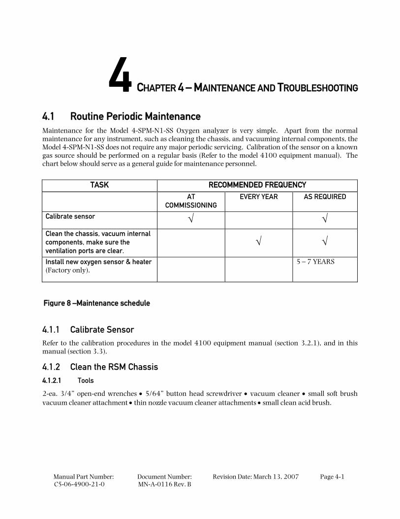
4.1 Routine Periodic Maintenance Maintenance for the Model 4-SPM-N1-SS Oxygen analyzer is very simple. Apart from the normal maintenance for any instrument, such as cleaning the chassis, and vacuuming internal components, the Model 4-SPM-N1-SS does not require any major periodic servicing. Calibration of the sensor on a known gas source should be performed on a regular basis (Refer to the model 4100 equipment manual). The chart below should serve as a general guide for maintenance personnel.
TASK RECOMMENDED FREQUENCY AT
COMMISSIONING EVERY YEAR AS REQUIRED
Calibrate sensor √ √ Clean the chassis, vacuum internal components, make sure the ventilation ports are clear.
√ √
Install new oxygen sensor & heater (Factory only).
5 – 7 YEARS
4.1.1 Calibrate Sensor Refer to the calibration procedures in the model 4100 equipment manual (section 3.2.1), and in this manual (section 3.3).
4.1.2 Clean the RSM Chassis 4.1.2.1 Tools
2-ea. 3/4” open-end wrenches • 5/64” button head screwdriver • vacuum cleaner • small soft brush vacuum cleaner attachment • thin nozzle vacuum cleaner attachments • small clean acid brush.
Figure 8 –Maintenance schedule
Maintenance and Troubleshooting
Manual Part Number: C5-06-4900-21-0
Document Number: MN-A-0116 Rev. B
Revision Date: March 13, 2007 Page 4-2
4.1.2.2 Procedure
Remove the RSM from on-line service (section 3.3.1). Unplug the RSM power cord. Disconnect the model 4100 analyzer interface connection.
Observe all lock-out/tag-out procedures. Hazardous voltages are present inside the chassis of the RSM. Do not remove any of the RSM chassis plates before removing mains power and the model 4100 interface connector from the unit.
Wait 30 to 60-minutes for the sensor heater to cool before removing any of the RSM chassis plates. The sensor heater assembly cover is hot to the touch during normal operation.
Using the vacuum cleaner and soft brush attachment, vacuum the exterior of the RSM chassis. Make sure that all louvers and vents are clear. Remove the top and side RSM chassis plates by removing the 18 button head machine screws from the unit. Set aside. Using the vacuum cleaner and soft brush attachment, vacuum the interior of the removed RSM chassis plates. Make sure that all louvers and vents are clear.
Using the vacuum cleaner and soft brush attachment, vacuum the interior components of the RSM assembly. Use the thin nozzle attachment, or small acid brush to reach places that cannot be reached with the soft brush vacuum attachment. Be careful not to damage internal wiring, terminal or soldered wire connections, oxygen sensor, or any other delicate components in the RSM.
Reassemble the RSM chassis, and return to on-line service.
4.1.3 Sensor Clean The presence of certain gases will cause a build-up of chemical deposits on the sensor electrodes, and temporarily blind the sensor, or skew its electrochemical zero-reference point. Sensor clean mode is to be used if the Zirconia oxide sensor is exposed to gases that may be affecting its ability to measure oxygen accurately, or respond to significant step changes in oxygen concentration within specifications.
4.1.3.1 Tools
2-ea. 3/4” open-end wrenches • Maintenance gas – Instrument grade compressed or bottled air
4.1.3.2 Procedure
Remove the RSM from on-line service, and apply Nitrogen or Instrument grade compressed air (section 3.3). Allow the applied gas to sweep through the sampling system for a minimum 15 minutes, to clear the sampling lines of gases potentially harmful to the oxygen sensor. From the model 4100 analyzer, initiate the sensor clean routine (Refer to the model 4100 equipment manual).
When sensor clean is complete, perform system calibration, and validate the display to a known test gas concentration (section 4.2.2.1). Re-calibrate if necessary, and return the RSM to on-line service.
4.1.4 Replace Oxygen Sensor Model 4-SPM-N1-SS oxygen sensor replacement must be performed by a certified Neutronics factory repair technician. Please contact the Ntron Service department.
Troubleshooting
Manual Part Number: C5-06-4900-21-0
Document Number: MN-A-0116 Rev.B
Revision Date: March 13, 2007
Page 4-3
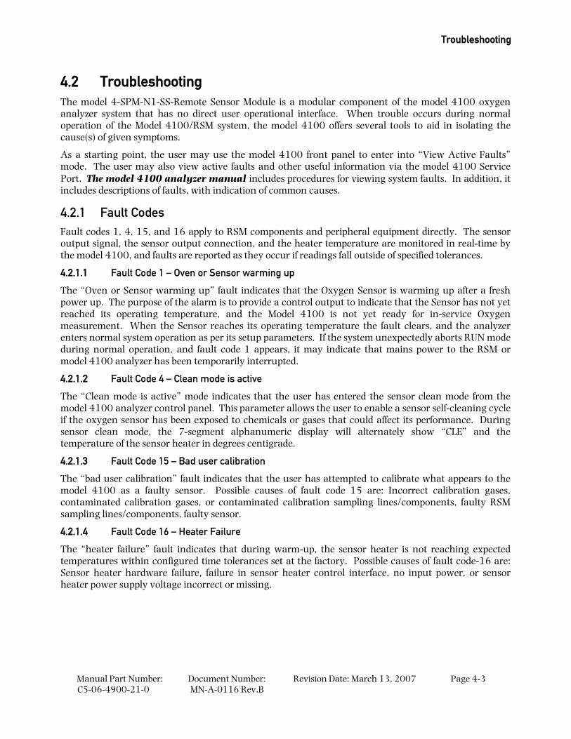
4.2 Troubleshooting The model 4-SPM-N1-SS-Remote Sensor Module is a modular component of the model 4100 oxygen analyzer system that has no direct user operational interface. When trouble occurs during normal operation of the Model 4100/RSM system, the model 4100 offers several tools to aid in isolating the cause(s) of given symptoms.
As a starting point, the user may use the model 4100 front panel to enter into “View Active Faults” mode. The user may also view active faults and other useful information via the model 4100 Service Port. The model 4100 analyzer manual includes procedures for viewing system faults. In addition, it includes descriptions of faults, with indication of common causes.
4.2.1 Fault Codes Fault codes 1, 4, 15, and 16 apply to RSM components and peripheral equipment directly. The sensor output signal, the sensor output connection, and the heater temperature are monitored in real-time by the model 4100, and faults are reported as they occur if readings fall outside of specified tolerances.
4.2.1.1 Fault Code 1 – Oven or Sensor warming up
The “Oven or Sensor warming up” fault indicates that the Oxygen Sensor is warming up after a fresh power up. The purpose of the alarm is to provide a control output to indicate that the Sensor has not yet reached its operating temperature, and the Model 4100 is not yet ready for in-service Oxygen measurement. When the Sensor reaches its operating temperature the fault clears, and the analyzer enters normal system operation as per its setup parameters. If the system unexpectedly aborts RUN mode during normal operation, and fault code 1 appears, it may indicate that mains power to the RSM or model 4100 analyzer has been temporarily interrupted.
4.2.1.2 Fault Code 4 – Clean mode is active
The “Clean mode is active” mode indicates that the user has entered the sensor clean mode from the model 4100 analyzer control panel. This parameter allows the user to enable a sensor self-cleaning cycle if the oxygen sensor has been exposed to chemicals or gases that could affect its performance. During sensor clean mode, the 7-segment alphanumeric display will alternately show “CLE” and the temperature of the sensor heater in degrees centigrade.
4.2.1.3 Fault Code 15 – Bad user calibration
The “bad user calibration” fault indicates that the user has attempted to calibrate what appears to the model 4100 as a faulty sensor. Possible causes of fault code 15 are: Incorrect calibration gases, contaminated calibration gases, or contaminated calibration sampling lines/components, faulty RSM sampling lines/components, faulty sensor.
4.2.1.4 Fault Code 16 – Heater Failure
The “heater failure” fault indicates that during warm-up, the sensor heater is not reaching expected temperatures within configured time tolerances set at the factory. Possible causes of fault code-16 are: Sensor heater hardware failure, failure in sensor heater control interface, no input power, or sensor heater power supply voltage incorrect or missing.
Maintenance and Troubleshooting
Manual Part Number: C5-06-4900-21-0
Document Number: MN-A-0116 Rev. B
Revision Date: March 13, 2007 Page 4-4
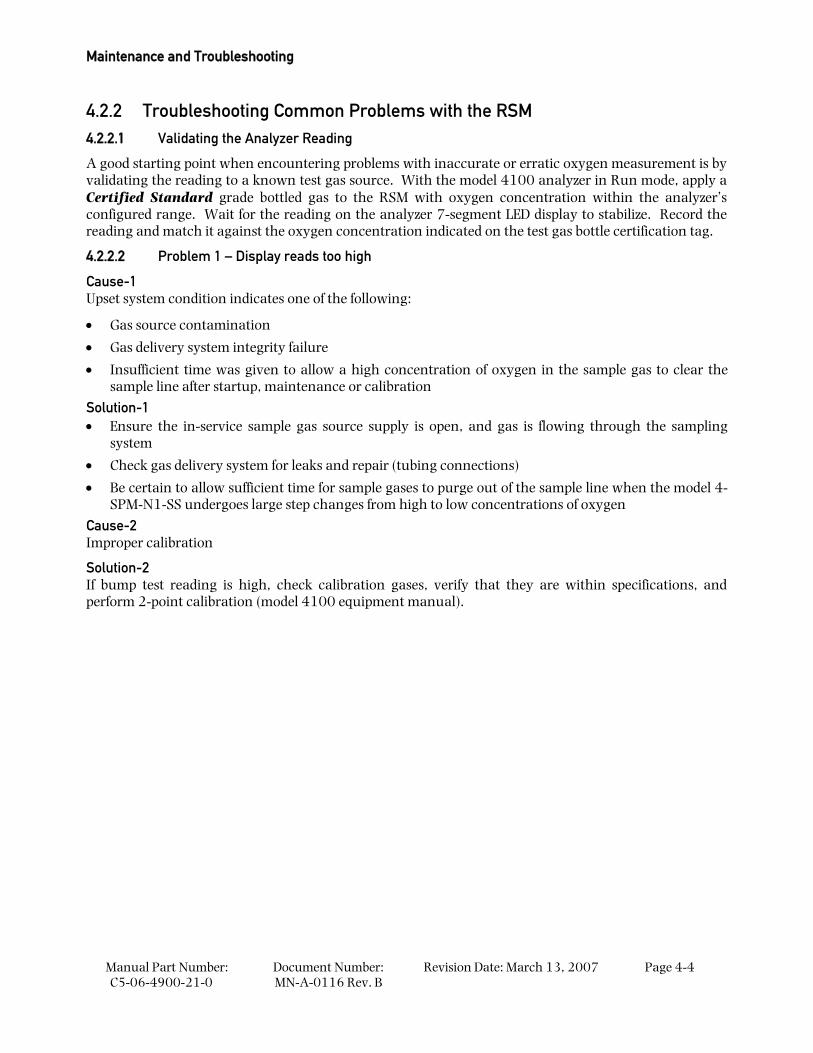
4.2.2 Troubleshooting Common Problems with the RSM 4.2.2.1 Validating the Analyzer Reading
A good starting point when encountering problems with inaccurate or erratic oxygen measurement is by validating the reading to a known test gas source. With the model 4100 analyzer in Run mode, apply a Certified Standard grade bottled gas to the RSM with oxygen concentration within the analyzer’s configured range. Wait for the reading on the analyzer 7-segment LED display to stabilize. Record the reading and match it against the oxygen concentration indicated on the test gas bottle certification tag.
4.2.2.2 Problem 1 – Display reads too high
Cause-1 Upset system condition indicates one of the following:
• Gas source contamination
• Gas delivery system integrity failure
• Insufficient time was given to allow a high concentration of oxygen in the sample gas to clear the sample line after startup, maintenance or calibration
Solution-1 • Ensure the in-service sample gas source supply is open, and gas is flowing through the sampling
system
• Check gas delivery system for leaks and repair (tubing connections)
• Be certain to allow sufficient time for sample gases to purge out of the sample line when the model 4-SPM-N1-SS undergoes large step changes from high to low concentrations of oxygen
Cause-2 Improper calibration
Solution-2 If bump test reading is high, check calibration gases, verify that they are within specifications, and perform 2-point calibration (model 4100 equipment manual).
Troubleshooting
Manual Part Number: C5-06-4900-21-0
Document Number: MN-A-0116 Rev.B
Revision Date: March 13, 2007
Page 4-5
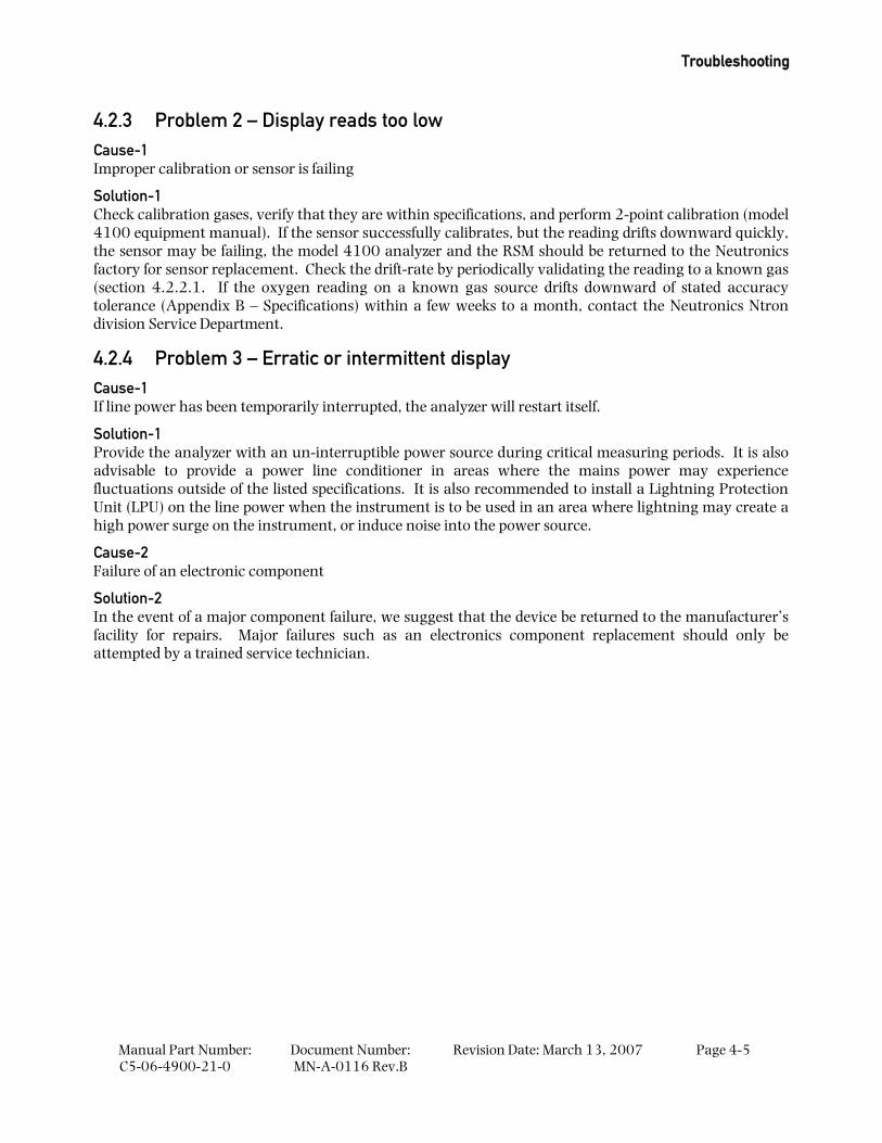
4.2.3 Problem 2 – Display reads too low Cause-1 Improper calibration or sensor is failing
Solution-1 Check calibration gases, verify that they are within specifications, and perform 2-point calibration (model 4100 equipment manual). If the sensor successfully calibrates, but the reading drifts downward quickly, the sensor may be failing, the model 4100 analyzer and the RSM should be returned to the Neutronics factory for sensor replacement. Check the drift-rate by periodically validating the reading to a known gas (section 4.2.2.1. If the oxygen reading on a known gas source drifts downward of stated accuracy tolerance (Appendix B – Specifications) within a few weeks to a month, contact the Neutronics Ntron division Service Department.
4.2.4 Problem 3 – Erratic or intermittent display Cause-1 If line power has been temporarily interrupted, the analyzer will restart itself.
Solution-1 Provide the analyzer with an un-interruptible power source during critical measuring periods. It is also advisable to provide a power line conditioner in areas where the mains power may experience fluctuations outside of the listed specifications. It is also recommended to install a Lightning Protection Unit (LPU) on the line power when the instrument is to be used in an area where lightning may create a high power surge on the instrument, or induce noise into the power source.
Cause-2 Failure of an electronic component
Solution-2 In the event of a major component failure, we suggest that the device be returned to the manufacturer’s facility for repairs. Major failures such as an electronics component replacement should only be attempted by a trained service technician.

Manual Part Number: C5-06-4900-21-0
Document Number: MN-A-0116 Rev. B
Revision Date: March 13, 2007 Page 5-1
5 CHAPTER 5 – APPENDICES
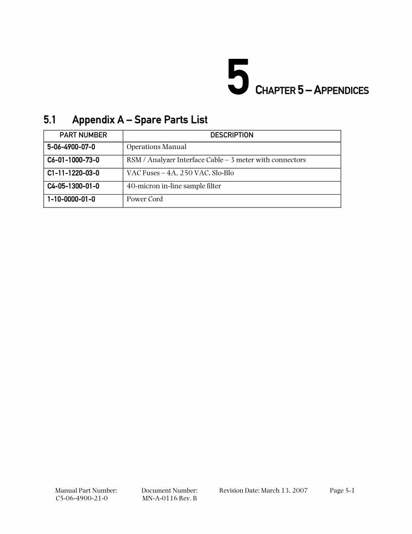
5.1 Appendix A – Spare Parts List PART NUMBER DESCRIPTION
5-06-4900-07-0 Operations Manual
C6-01-1000-73-0 RSM / Analyzer Interface Cable – 3 meter with connectors
C1-11-1220-03-0 VAC Fuses – 4A, 250 VAC, Slo-Blo
C4-05-1300-01-0 40-micron in-line sample filter
1-10-0000-01-0 Power Cord
Appendices
Manual Part Number: C5-06-4900-21-0
Document Number: MN-A-0116 Rev. B
Revision Date: March 13, 2007 Page 5-2
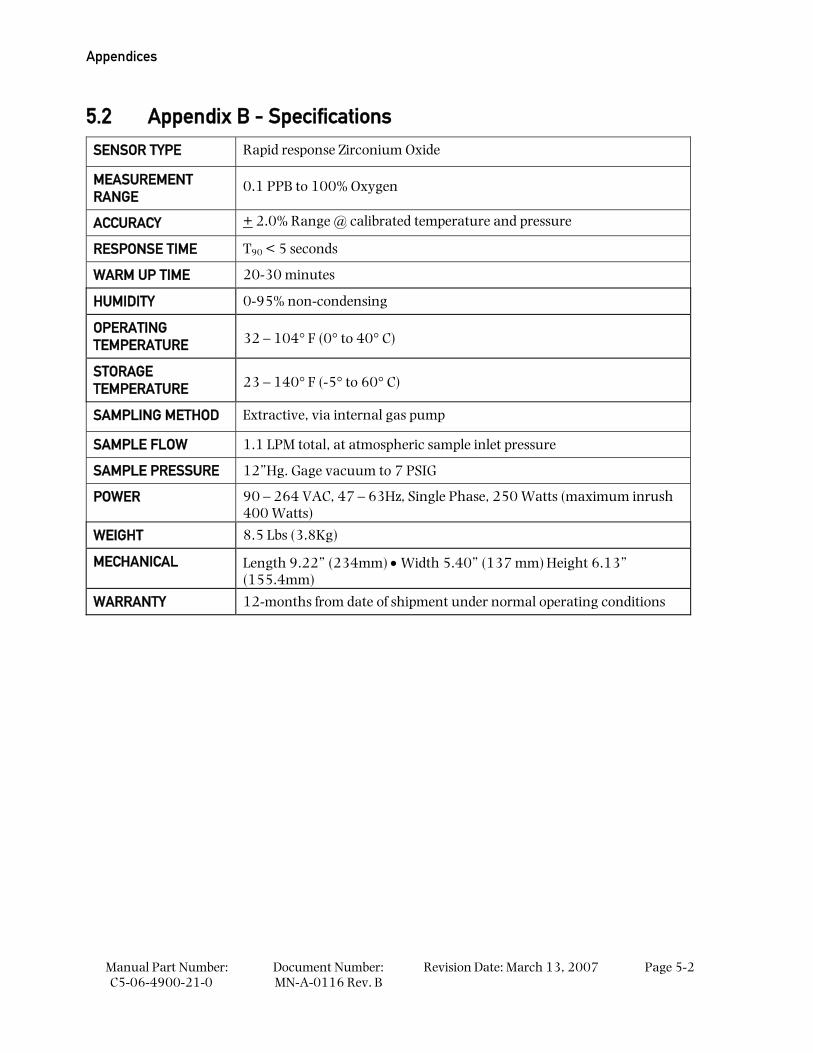
5.2 Appendix B - Specifications
SENSOR TYPE Rapid response Zirconium Oxide
MEASUREMENT RANGE
0.1 PPB to 100% Oxygen
ACCURACY + 2.0% Range @ calibrated temperature and pressure
RESPONSE TIME T90 < 5 seconds
WARM UP TIME 20-30 minutes
HUMIDITY 0-95% non-condensing
OPERATING TEMPERATURE 32 – 104° F (0° to 40° C)
STORAGE TEMPERATURE 23 – 140° F (-5° to 60° C)
SAMPLING METHOD Extractive, via internal gas pump
SAMPLE FLOW 1.1 LPM total, at atmospheric sample inlet pressure
SAMPLE PRESSURE 12”Hg. Gage vacuum to 7 PSIG
POWER 90 – 264 VAC, 47 – 63Hz, Single Phase, 250 Watts (maximum inrush 400 Watts)
WEIGHT 8.5 Lbs (3.8Kg)
MECHANICAL Length 9.22” (234mm) • Width 5.40” (137 mm) Height 6.13” (155.4mm)
WARRANTY 12-months from date of shipment under normal operating conditions
Appendix C – MSDS Material Safety Data Sheet
Manual Part Number: C5-06-4900-21-0
Document Number: MN-A-0116 Rev.B
Revision Date: March 13, 2007
Page 5-3
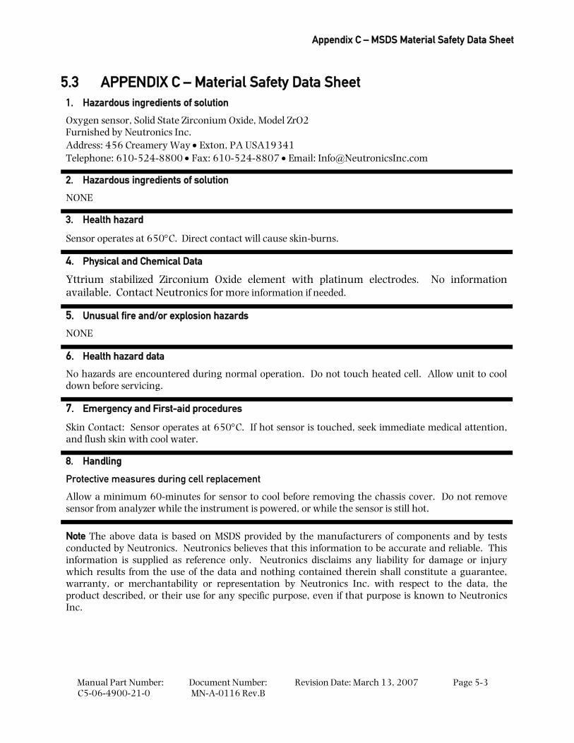
5.3 APPENDIX C – Material Safety Data Sheet 1. Hazardous ingredients of solution
Oxygen sensor, Solid State Zirconium Oxide, Model ZrO2 Furnished by Neutronics Inc. Address: 456 Creamery Way • Exton, PA USA19341 Telephone: 610-524-8800 • Fax: 610-524-8807 • Email: [email protected]
2. Hazardous ingredients of solution
NONE
3. Health hazard
Sensor operates at 650°C. Direct contact will cause skin-burns.
4. Physical and Chemical Data
Yttrium stabilized Zirconium Oxide element with platinum electrodes. No information available. Contact Neutronics for more information if needed.
5. Unusual fire and/or explosion hazards
NONE
6. Health hazard data
No hazards are encountered during normal operation. Do not touch heated cell. Allow unit to cool down before servicing.
7. Emergency and First-aid procedures
Skin Contact: Sensor operates at 650°C. If hot sensor is touched, seek immediate medical attention, and flush skin with cool water.
8. Handling
Protective measures during cell replacement
Allow a minimum 60-minutes for sensor to cool before removing the chassis cover. Do not remove sensor from analyzer while the instrument is powered, or while the sensor is still hot.
Note The above data is based on MSDS provided by the manufacturers of components and by tests conducted by Neutronics. Neutronics believes that this information to be accurate and reliable. This information is supplied as reference only. Neutronics disclaims any liability for damage or injury which results from the use of the data and nothing contained therein shall constitute a guarantee, warranty, or merchantability or representation by Neutronics Inc. with respect to the data, the product described, or their use for any specific purpose, even if that purpose is known to Neutronics Inc.
Appendices
Manual Part Number: C5-06-4900-21-0
Document Number: MN-A-0116 Rev. B
Revision Date: March 13, 2007 Page 5-4
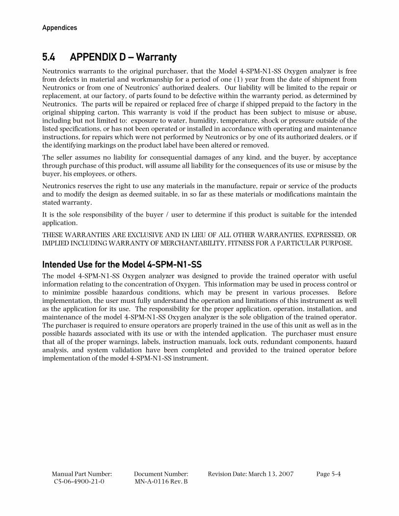
5.4 APPENDIX D – Warranty Neutronics warrants to the original purchaser, that the Model 4-SPM-N1-SS Oxygen analyzer is free from defects in material and workmanship for a period of one (1) year from the date of shipment from Neutronics or from one of Neutronics’ authorized dealers. Our liability will be limited to the repair or replacement, at our factory, of parts found to be defective within the warranty period, as determined by Neutronics. The parts will be repaired or replaced free of charge if shipped prepaid to the factory in the original shipping carton. This warranty is void if the product has been subject to misuse or abuse, including but not limited to: exposure to water, humidity, temperature, shock or pressure outside of the listed specifications, or has not been operated or installed in accordance with operating and maintenance instructions, for repairs which were not performed by Neutronics or by one of its authorized dealers, or if the identifying markings on the product label have been altered or removed.
The seller assumes no liability for consequential damages of any kind, and the buyer, by acceptance through purchase of this product, will assume all liability for the consequences of its use or misuse by the buyer, his employees, or others.
Neutronics reserves the right to use any materials in the manufacture, repair or service of the products and to modify the design as deemed suitable, in so far as these materials or modifications maintain the stated warranty.
It is the sole responsibility of the buyer / user to determine if this product is suitable for the intended application.
THESE WARRANTIES ARE EXCLUSIVE AND IN LIEU OF ALL OTHER WARRANTIES, EXPRESSED, OR IMPLIED INCLUDING WARRANTY OF MERCHANTABILITY, FITNESS FOR A PARTICULAR PURPOSE.
Intended Use for the Model 4-SPM-N1-SS The model 4-SPM-N1-SS Oxygen analyzer was designed to provide the trained operator with useful information relating to the concentration of Oxygen. This information may be used in process control or to minimize possible hazardous conditions, which may be present in various processes. Before implementation, the user must fully understand the operation and limitations of this instrument as well as the application for its use. The responsibility for the proper application, operation, installation, and maintenance of the model 4-SPM-N1-SS Oxygen analyzer is the sole obligation of the trained operator. The purchaser is required to ensure operators are properly trained in the use of this unit as well as in the possible hazards associated with its use or with the intended application. The purchaser must ensure that all of the proper warnings, labels, instruction manuals, lock outs, redundant components, hazard analysis, and system validation have been completed and provided to the trained operator before implementation of the model 4-SPM-N1-SS instrument.