Embed Size (px)
Citation preview

Engineering 80 – Spring 2015
Temperature Measurements
SOURCE: http://elcodis.com/photos/19/51/195143/to-92-3_standardbody__to-226_straightlead.jpg
SOURCE: http://www.accuglassproducts.com/product.php?productid=17523
SOURCE: http://www.eng.hmc.edu/NewE80/PDFs/VIshayThermDataSheet.pdf
1
Key Concepts
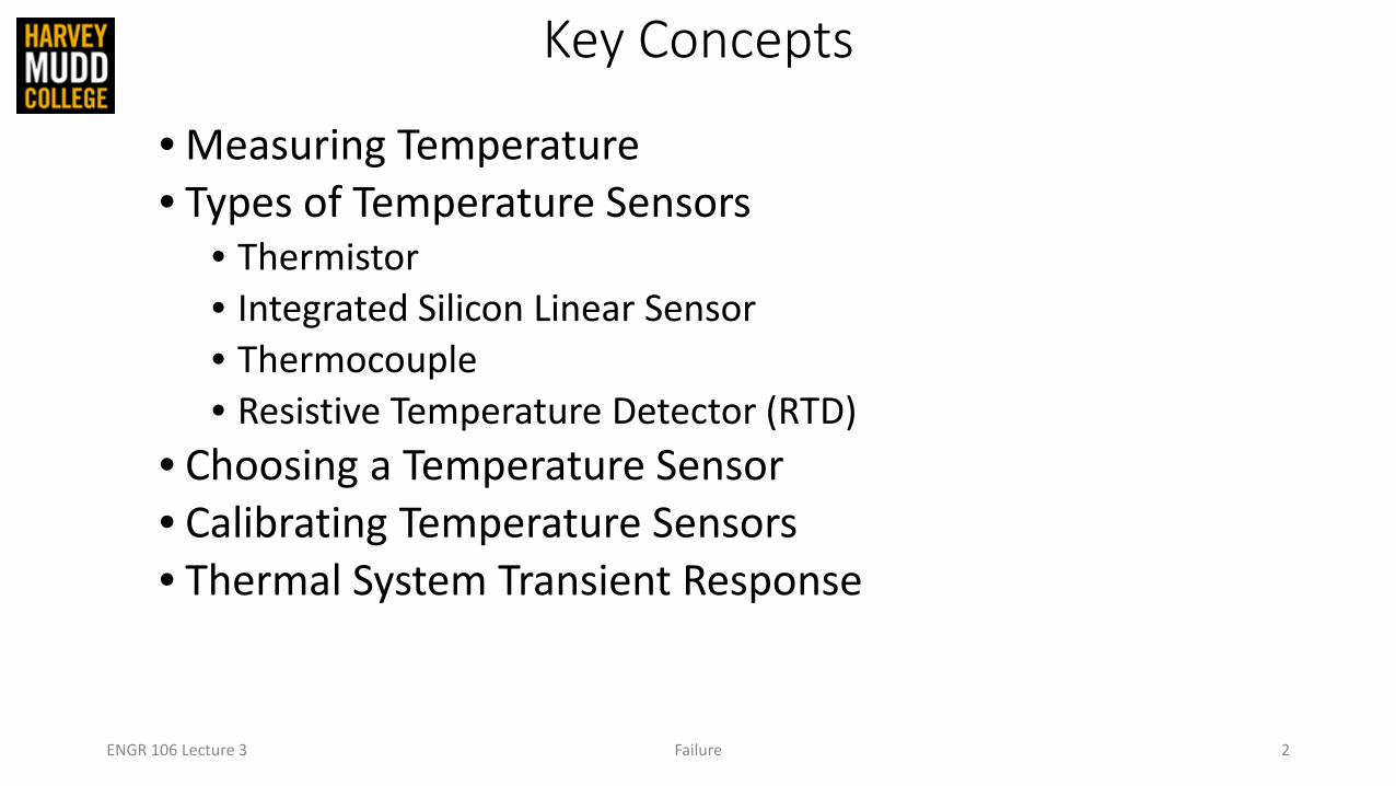
• Measuring Temperature• Types of Temperature Sensors
• Thermistor• Integrated Silicon Linear Sensor• Thermocouple• Resistive Temperature Detector (RTD)
• Choosing a Temperature Sensor• Calibrating Temperature Sensors• Thermal System Transient Response
ENGR 106 Lecture 3 Failure 2

What is Temperature?
ENGINEERING 80 Temperature Measurements 3
SOURCE: http://www.clker.com/cliparts/6/5/b/f/11949864691020941855smiley114.svg.med.png

What is Temperature?
ENGINEERING 80 Temperature Measurements 4
AN OVERLY SIMPLIFIED DESCRIPTION OF TEMPERATURE
"Temperature is a measure of the tendency of an object to spontaneously give up energy to its surroundings. When two objects are in thermal contact, the one that tends to
spontaneously lose energy is at the higher temperature.“(Schroeder, Daniel V. An Introduction to Thermal Physics, 1st Edition (Ch, 1). Addison-Wesley.)
SOURCE: http://hyperphysics.phy-astr.gsu.edu/hbase/thermo/temper2.html#c1

What is Temperature?
ENGINEERING 80 Temperature Measurements 5
A SIMPLIFIED DESCRIPTION OF TEMPERATURE
"Temperature is a measure of the tendency of an object to spontaneously give up energy to its surroundings. When two objects are in thermal contact, the one that tends to
spontaneously lose energy is at the higher temperature.“(Schroeder, Daniel V. An Introduction to Thermal Physics, 1st Edition (Ch, 1). Addison-Wesley.)
SOURCE: http://hyperphysics.phy-astr.gsu.edu/hbase/thermo/temper2.html#c1

Measuring Temperature with Rockets
ENGINEERING 80 Temperature Measurements 6
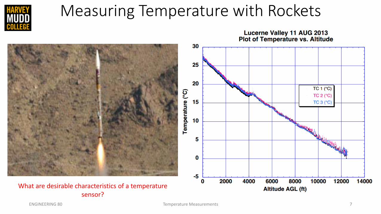
Measuring Temperature with Rockets
ENGINEERING 80 Temperature Measurements 7
What are desirable characteristics of a temperature sensor?
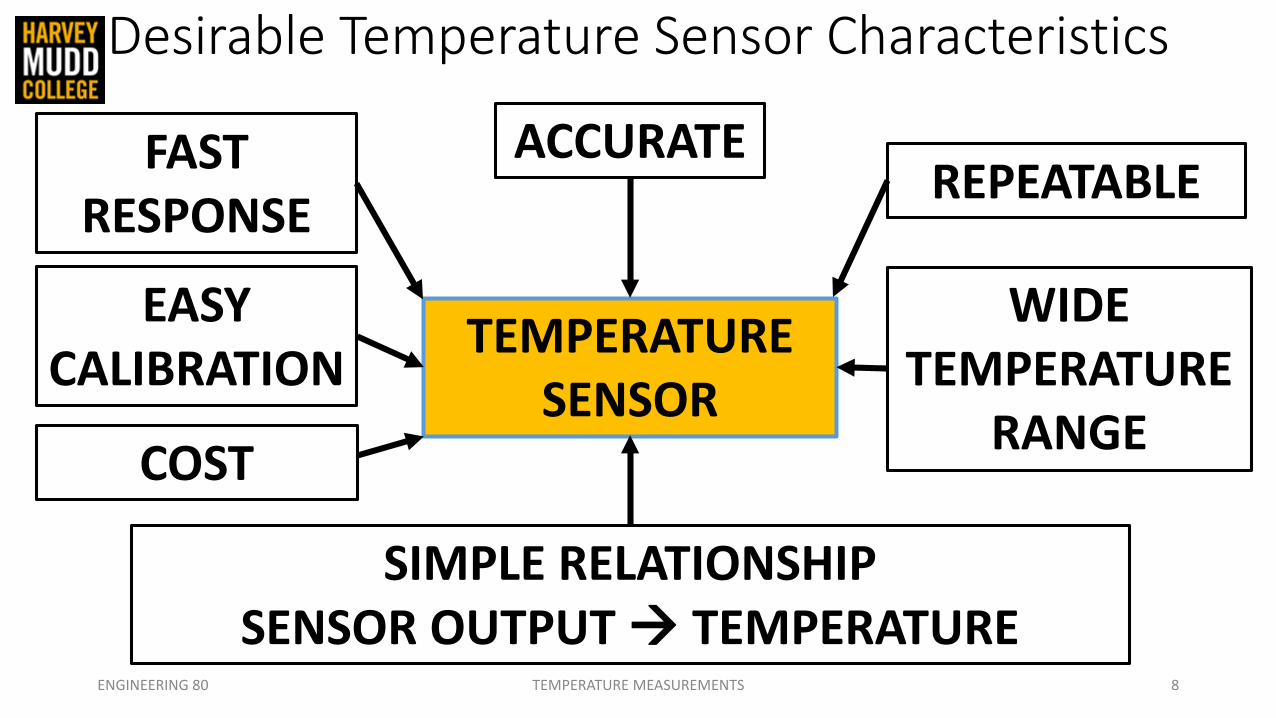
Desirable Temperature Sensor Characteristics
ENGINEERING 80 TEMPERATURE MEASUREMENTS 8
ACCURATEREPEATABLE
WIDE TEMPERATURE
RANGE
EASY CALIBRATION
FAST RESPONSE
SIMPLE RELATIONSHIPSENSOR OUTPUT TEMPERATURE
TEMPERATURE SENSOR
COST

Thermistor
ENGR 106 Lecture 3 Temperature Measurements 9
Thermistor – a resistor whose resistance changes with temperature

Thermistor
ENGR 106 Lecture 3 Temperature Measurements 10
Thermistor – a resistor whose resistance changes with temperature
• Resistive element is generally a metal-oxide ceramic containing Mn, Co, Cu, or Ni
• Packaged in a thermally conductive glass bead or disk with two metal leads

Thermistor
ENGR 106 Lecture 3 Temperature Measurements 11
Thermistor – a resistor whose resistance changes with temperature
• Resistive element is generally a metal-oxide ceramic containing Mn, Co, Cu, or Ni
• Packaged in a thermally conductive glass bead or disk with two metal leads
• Suppose we have a “1 kΩ thermistor”…• What does this mean?

Thermistor
ENGR 106 Lecture 3 Temperature Measurements 12
Thermistor – a resistor whose resistance changes with temperature
• Resistive element is generally a metal-oxide ceramic containing Mn, Co, Cu, or Ni
• Packaged in a thermally conductive glass bead or disk with two metal leads
• Suppose we have a “1 kΩ thermistor” …• What does this mean?• At room temperature, the resistance of
the thermistor is 1 kΩ

Thermistor
ENGR 106 Lecture 3 Temperature Measurements 13
Thermistor – a resistor whose resistance changes with temperature
• Resistive element is generally a metal-oxide ceramic containing Mn, Co, Cu, or Ni
• Packaged in a thermally conductive glass bead or disk with two metal leads
• Suppose we have a “1 kΩ thermistor”• What does this mean?• At room temperature, the resistance of
the thermistor is 1 kΩ• What happens to resistance as we
increase temperature?

Negative Temperature Coefficient
• Most materials exhibit a negative temperature coefficient (NTC)• Resistance drops with temperature!
ENGINEERING 80 Temperature Measurements 14

Converting Resistance to Temperature• The Steinhart-Hart Equation relates temperature to resistance
ENGINEERING 80 Temperature Measurements 15
SOURCE: http://p.globalsources.com/IMAGES/PDT/B1055847338/Thermistor.jpg

Converting Resistance to Temperature• The Steinhart-Hart Equation relates temperature to resistance
• T is the temperature (in Kelvin)• R is the resistance at T and Rref is resistance at Tref
• A1, B1, C1, and D1 are the Steinhart-Hart Coefficients• HOW COULD WE DETERMINE THESE COEFFICIENTS?
ENGINEERING 80 Temperature Measurements 16
SOURCE: http://p.globalsources.com/IMAGES/PDT/B1055847338/Thermistor.jpg

Converting Resistance to Temperature• The Steinhart-Hart Equation relates temperature to resistance
• T is the temperature (in Kelvin)• R is the resistance at T and Rref is resistance at Tref
• A1, B1, C1, and D1 are the Steinhart-Hart Coefficients• HOW COULD WE DETERMINE THESE COEFFICIENTS?
• Take a look at the data sheet
ENGINEERING 80 Temperature Measurements 17
SOURCE: http://p.globalsources.com/IMAGES/PDT/B1055847338/Thermistor.jpg

Converting Resistance to Temperature
ENGINEERING 80 Temperature Measurements 18

Converting Resistance to Temperature
ENGINEERING 80 Temperature Measurements 19

Converting Resistance to Temperature
ENGINEERING 80 Temperature Measurements 20
WHAT IF YOU LOST THE DATA SHEET, DON’T BELIEVE IT, OR WOULD LIKE TO VERIFY THE VALUES?

Converting Resistance to Temperature• The Steinhart-Hart Equation relates temperature to resistance
• T is the temperature (in Kelvin)• R is the resistance at T and Rref is resistance at Tref
• A1, B1, C1, and D1 are the Steinhart-Hart Coefficients• HOW COULD WE DETERMINE THESE COEFFICIENTS?
• Take a look at the data sheet
ENGINEERING 80 Temperature Measurements 21
SOURCE: http://p.globalsources.com/IMAGES/PDT/B1055847338/Thermistor.jpg

Converting Resistance to Temperature• The Steinhart-Hart Equation relates temperature to resistance
• T is the temperature (in Kelvin)• R is the resistance at T and Rref is resistance at Tref
• A1, B1, C1, and D1 are the Steinhart-Hart Coefficients• HOW COULD WE DETERMINE THESE COEFFICIENTS?
• Take a look at the data sheet• Measure 3 resistances at 3 temperatures
• Matrix Inversion (Linear Algebra)
ENGINEERING 80 Temperature Measurements 22
SOURCE: http://p.globalsources.com/IMAGES/PDT/B1055847338/Thermistor.jpg

Converting Resistance to Temperature• The Steinhart-Hart Equation relates temperature to resistance
• T is the temperature (in Kelvin)• R is the resistance at T and Rref is resistance at Tref
• A1, B1, C1, and D1 are the Steinhart-Hart Coefficients• HOW COULD WE DETERMINE THESE COEFFICIENTS?
• Take a look at the data sheet• Measure 3 resistances at 3 temperatures
• Matrix Inversion (Linear Algebra)• Least Squares Fit
ENGINEERING 80 Temperature Measurements 23
SOURCE: http://p.globalsources.com/IMAGES/PDT/B1055847338/Thermistor.jpg

SOURCE: http://p.globalsources.com/IMAGES/PDT/B1055847338/Thermistor.jpg
How is Resistance Measured?
ENGINEERING 80 Temperature Measurements 24

Thermistor Resistance (RT)
• A thermistor produces a resistance (RT), which must be converted to a voltage signal
ENGINEERING 80 Temperature Measurements 25
1RRRVV
T
TSout +
=
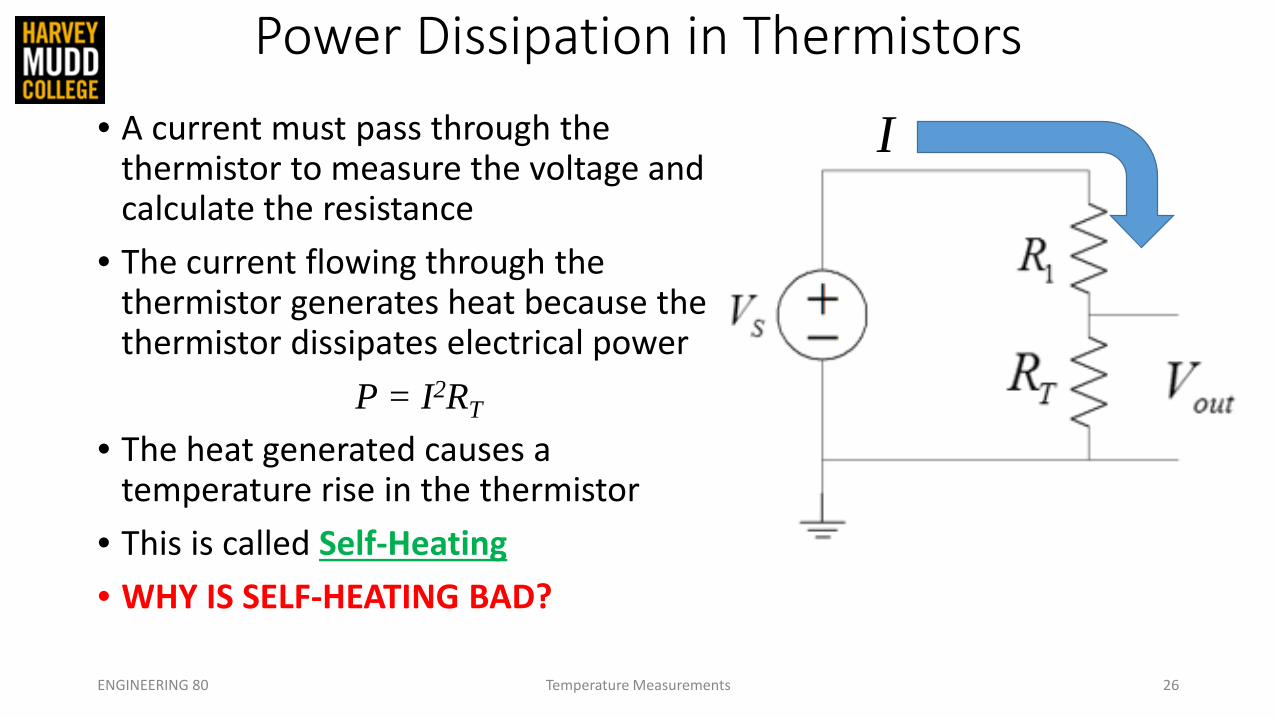
Power Dissipation in Thermistors• A current must pass through the
thermistor to measure the voltage and calculate the resistance
• The current flowing through the thermistor generates heat because the thermistor dissipates electrical power
P = I2RT
• The heat generated causes a temperature rise in the thermistor
• This is called Self-Heating• WHY IS SELF-HEATING BAD?
ENGINEERING 80 Temperature Measurements 26
I

Power Dissipation and Self-Heating• Self-Heating can introduce an error into the measurement• The increase in device temperature (ΔT) is related to the power dissipated
(P) and the power dissipation factor (δ)P = δ ΔT
Where P is in [W], ΔT is the rise in temperature in [oC]• Suppose I = 5 mA, RT = 4 kΩ, and δ = 0.067 W/oC, what is ΔT?
ENGINEERING 80 Temperature Measurements 27

Power Dissipation and Self-Heating• Self-Heating can introduce an error into the measurement• The increase in device temperature (ΔT) is related to the power dissipated
(P) and the power dissipation factor (δ)P = δ ΔT
Where P is in [W], ΔT is the rise in temperature in [oC]• Suppose I = 5 mA, RT = 4 kΩ, and δ = 0.067 W/oC, what is ΔT?
(0.005 A)2(4000 Ω) = (0.067 W/oC) ΔTΔT = 1.5 oC
• What effect does a ΔT of 1.5 oC have on your thermistor measurements?
ENGINEERING 80 Temperature Measurements 28

Power Dissipation and Self-Heating• Self-Heating can introduce an error into the measurement• The increase in device temperature (ΔT) is related to the power dissipated
(P) and the power dissipation factor (δ)P = δ ΔT
Where P is in [W], ΔT is the rise in temperature in [oC]• Suppose I = 5 mA, RT = 4 kΩ, and δ = 0.067 W/oC, what is ΔT?
(0.005 A)2(4000 Ω) = (0.067 W/oC) ΔTΔT = 1.5 oC
• What effect does a ΔT of 1.5 oC have on your thermistor measurements?• How can we reduce the effects of self-heating?
ENGINEERING 80 Temperature Measurements 29

Power Dissipation and Self-Heating• Self-Heating can introduce an error into the measurement• The increase in device temperature (ΔT) is related to the power dissipated
(P) and the power dissipation factor (δ)P = δ ΔT
Where P is in [W], ΔT is the rise in temperature in [oC]• Suppose I = 5 mA, RT = 4 kΩ, and δ = 0.067 W/oC, what is ΔT?
(0.005 A)2(4000 Ω) = (0.067 W/oC) ΔTΔT = 1.5 oC
• What effect does a ΔT of 1.5 oC have on your thermistor measurements?• How can we reduce the effects of self-heating?
• Increase the resistance of the thermistor!ENGINEERING 80 Temperature Measurements 30

Thermistor Signal Conditioning Circuit• A voltage divider and a unity gain buffer are required to measure
temperature in the lab
ENGINEERING 80 Temperature Measurements 31
REF195
1/4AD8606
(AD8605)
+
-10k
Thermistor
To ADC
buffer
+5 V reference
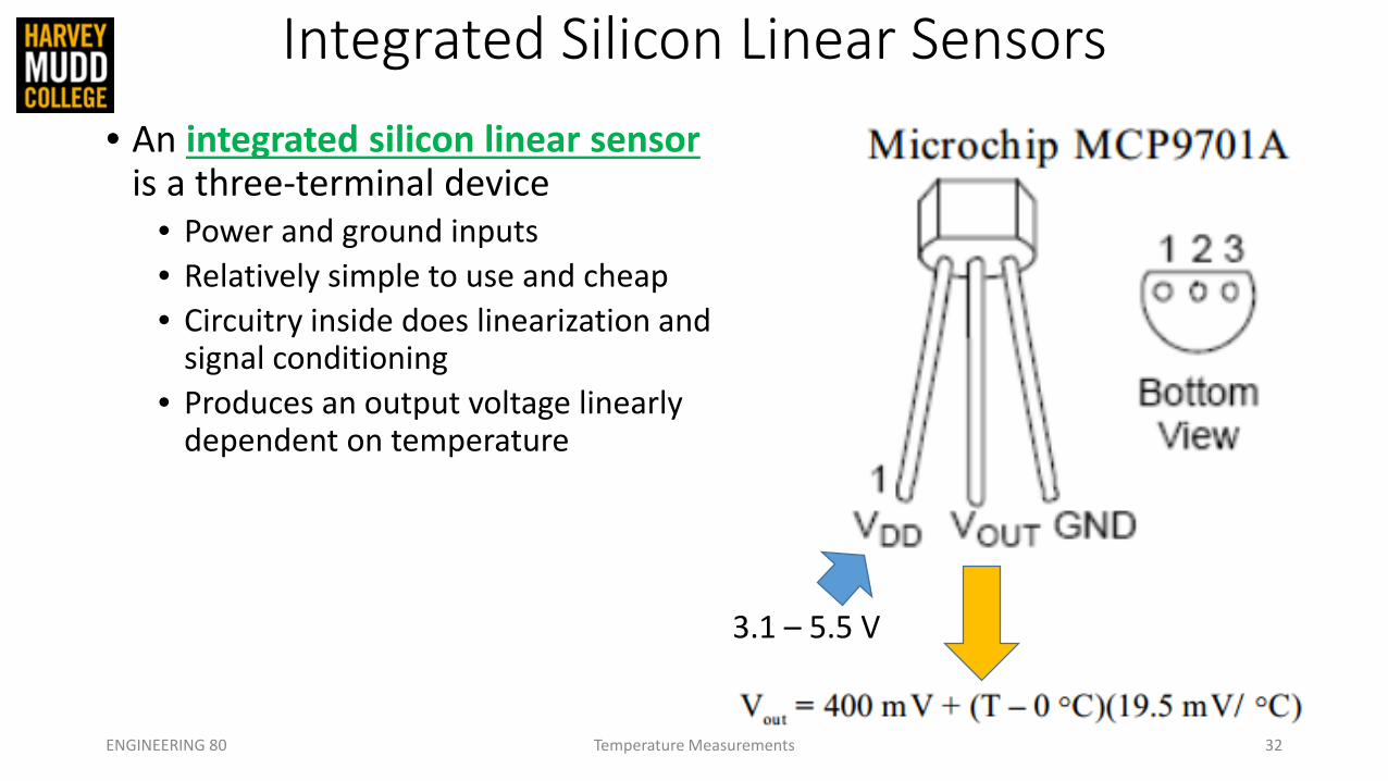
Integrated Silicon Linear Sensors• An integrated silicon linear sensor
is a three-terminal device• Power and ground inputs• Relatively simple to use and cheap• Circuitry inside does linearization and
signal conditioning• Produces an output voltage linearly
dependent on temperature
ENGINEERING 80 Temperature Measurements 32
3.1 – 5.5 V

Integrated Silicon Linear Sensors• An integrated silicon linear sensor
is a three-terminal device• Power and ground inputs• Relatively simple to use and cheap• Circuitry inside does linearization and
signal conditioning• Produces an output voltage linearly
dependent on temperature• When compared to other
temperature measurement devices, these sensors are less accurate, operate over a narrower temperature range, and are less responsive
ENGINEERING 80 Temperature Measurements 33
3.1 – 5.5 V

Summary Thus Far…
ENGINEERING 80 Temperature Measurements 34
>

Thermocouple• Thermocouple – a two-terminal element consisting of two dissimilar
metal wires joined at the end
ENGINEERING 80 Temperature Measurements 35
SOURCE: http://upload.wikimedia.org/wikipedia/en/e/ed/Thermocouple_(work_diagram)_LMB.png

The Seebeck Effect• Seebeck Effect – A conductor generates a voltage when it is
subjected to a temperature gradient
ENGINEERING 80 Temperature Measurements 36

The Seebeck Effect• Seebeck Effect – A conductor generates a voltage when it is
subjected to a temperature gradient• Measuring this voltage requires the use of a second conductor material
ENGINEERING 80 Temperature Measurements 37
Will I observe a difference in
voltage at the ends of two wires composed of the same material?
Nickel-Chromium Alloy
Nickel-Chromium Alloy

The Seebeck Effect• Seebeck Effect – A conductor generates a voltage when it is
subjected to a temperature gradient• Measuring this voltage requires the use of a second conductor material• The other material needs to be composed of a different material
ENGINEERING 80 Temperature Measurements 38
Nickel-Chromium Alloy
Copper-Nickel Alloy
The relationship between
temperature difference and voltage varies with materials

The Seebeck Effect• Seebeck Effect – A conductor generates a voltage when it is
subjected to a temperature gradient• Measuring this voltage requires the use of a second conductor material• The other material needs to be composed of a different material
ENGINEERING 80 Temperature Measurements 39
The voltage difference of the two dissimilar metals can be measured and related to the corresponding temperature
gradient
Nickel-Chromium Alloy
Copper-Nickel Alloy
The relationship between
temperature difference and voltage varies with materials
+
-
VS = SΔT
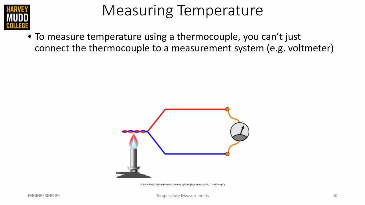
Measuring Temperature• To measure temperature using a thermocouple, you can’t just
connect the thermocouple to a measurement system (e.g. voltmeter)
ENGINEERING 80 Temperature Measurements 40
SOURCE: http://www.pcbheaven.com/wikipages/images/thermocouples_1271330366.png

Measuring Temperature• To measure temperature using a thermocouple, you can’t just
connect the thermocouple to a measurement system (e.g. voltmeter)• The voltage measured by your system is proportional to the
temperature difference between the primary junction (hot junction) and the junction where the voltage is being measured (Ref junction)
ENGINEERING 80 Temperature Measurements 41
SOURCE: http://www.pcbheaven.com/wikipages/images/thermocouples_1271330366.png

Measuring Temperature• To measure temperature using a thermocouple, you can’t just
connect the thermocouple to a measurement system (e.g. voltmeter)• The voltage measured by your system is proportional to the
temperature difference between the primary junction (hot junction) and the junction where the voltage is being measured (Ref junction)
ENGINEERING 80 Temperature Measurements 42
SOURCE: http://www.pcbheaven.com/wikipages/images/thermocouples_1271330366.png
To determine the absolute
temperature at the hot
junction…
You need to know the
temperature at the Ref junction!

Measuring Temperature• To measure temperature using a thermocouple, you can’t just
connect the thermocouple to a measurement system (e.g. voltmeter)• The voltage measured by your system is proportional to the
temperature difference between the primary junction (hot junction) and the junction where the voltage is being measured (Ref junction)
ENGINEERING 80 Temperature Measurements 43
SOURCE: http://www.pcbheaven.com/wikipages/images/thermocouples_1271330366.png
To determine the absolute
temperature at the hot
junction…
You need to know the
temperature at the Ref junction!
How can we determine the temperature at the
reference junction?

Ice Bath Method (Forcing a Temperature)• Thermocouples measure the voltage difference between two points• To know the absolute temperature at the hot junction, one must know the
temperature at the Ref junction
ENGINEERING 80 Temperature Measurements 44

Ice Bath Method (Forcing a Temperature)• Thermocouples measure the voltage difference between two points• To know the absolute temperature at the hot junction, one must know the
temperature at the Ref junction
ENGINEERING 80 Temperature Measurements 45
• NIST thermocouple reference tables are generated with Tref = 0 oC
Vmeas = V(Thot) – V(Tref)
V(Vhot) = Vmeas + V(Tref)
If we know the voltage-temperature relationship of our thermocouple, we could
determine the temperature at the hot junctionIS IT REALLY THAT EASY?

Nonlinearity in the Seebeck Coefficient
• Thermocouple output voltages are highly nonlinear
• The Seebeck coefficient can vary by a factor of 3 or more over the operating temperature range of the thermocouples
ENGINEERING 80 Temperature Measurements 46
VS = SΔT

Temperature Conversion Equation
T = a0 + a1V + a2V2 + …. + anVn
ENGINEERING 80 Temperature Measurements 47
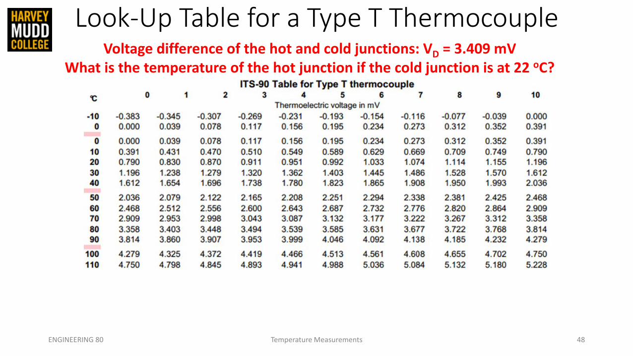
Look-Up Table for a Type T Thermocouple
ENGINEERING 80 Temperature Measurements 48
Voltage difference of the hot and cold junctions: VD = 3.409 mVWhat is the temperature of the hot junction if the cold junction is at 22 oC?

Look-Up Table for a Type T Thermocouple
ENGINEERING 80 Temperature Measurements 49
Voltage difference of the hot and cold junctions: VD = 3.409 mVWhat is the temperature of the hot junction if the cold junction is at 22 oC?
At 22 oC, the reference junction voltage is 0.870 mVThe hot junction voltage is therefore 3.409 mV + 0.870 mV = 4.279 mV
The temperature at the hot junction is therefore 100 oC

APPLYING WHAT WE’VE LEARNED
ENGINEERING 80 Temperature Measurements 50
Voltage difference of the hot and cold junctions: VD = 4.472 mVWhat is the temperature of the hot junction if the cold junction is at –5 oC?

APPLYING WHAT WE’VE LEARNED
ENGINEERING 80 Temperature Measurements 51
Voltage difference of the hot and cold junctions: VD = 4.472 mVWhat is the temperature of the hot junction if the cold junction is at –5 oC?
At -5 oC, the cold junction voltage is –0.193 mVThe hot junction voltage is therefore 4.472 mV – 0.193 mV = 4.279 mV
The temperature at the hot junction is therefore 100 oC
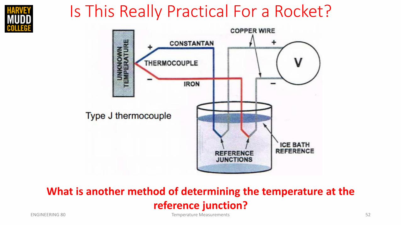
Is This Really Practical For a Rocket?
ENGINEERING 80 Temperature Measurements 52
What is another method of determining the temperature at the reference junction?

Cold Junction Compensation
ENGINEERING 80 Temperature Measurements 53
SOURCE: http://www.industrial-electronics.com/DAQ/images/10_13.jpg
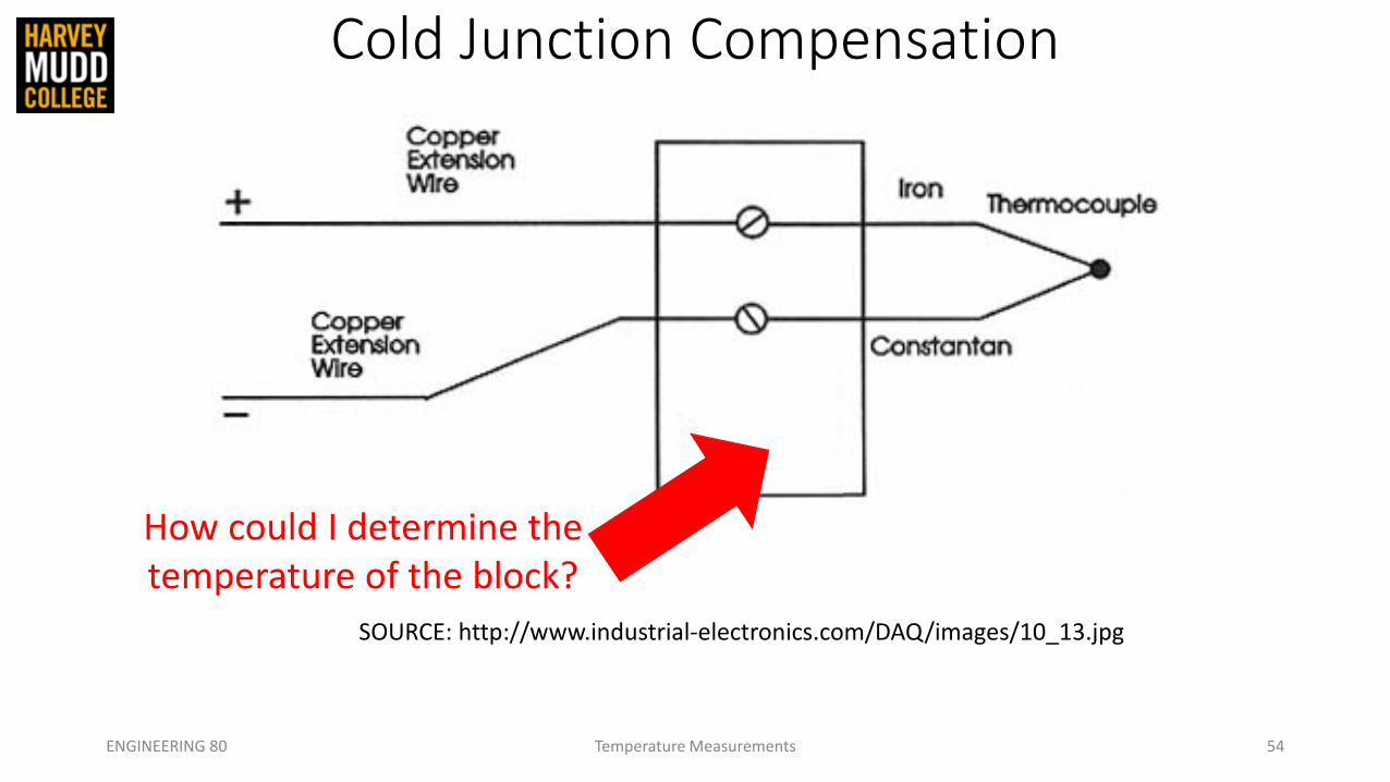
Cold Junction Compensation
ENGINEERING 80 Temperature Measurements 54
SOURCE: http://www.industrial-electronics.com/DAQ/images/10_13.jpg
How could I determine the temperature of the block?

Cold Junction Compensation
ENGINEERING 80 Temperature Measurements 55
SOURCE: http://www.industrial-electronics.com/DAQ/images/10_13.jpg

Acquiring Data
ENGINEERING 80 Temperature Measurements 56

Temperature Measurement Devices in Lab
ENGINEERING 80 Temperature Measurements 57
>

Resistive Temperature Detector (RTD)• Two terminal device• Usually made out of platinum• Positive temperature coefficient• Tends to be linear• R = R0(1+α)(T-T0) where T0 = 0oC
R0 = 100 Ω, α = 0.03385 Ω/ Ω oC• At 10oC, R = 100(1+0.385)(10) = 103.85 Ω• They are best operated using a small
constant current source• Accuracy of 0.01 oC• EXPENSIVE!ENGINEERING 80 Temperature Measurements 58
SOURCE: http://www.omega.com/prodinfo/images/RTD_diag1.gif

Temperature Measurement Devices
ENGINEERING 80 Temperature Measurements 59
>

How Do I Know If These Are Working?
ENGINEERING 80 Temperature Measurements 60
SOURCE: http://elcodis.com/photos/19/51/195143/to-92-3_standardbody__to-226_straightlead.jpg
SOURCE: http://www.accuglassproducts.com/product.php?productid=17523
SOURCE: http://www.eng.hmc.edu/NewE80/PDFs/VIshayThermDataSheet.pdf
Calibration• How could we calibrate a temperature sensor?
ENGINEERING 80 Temperature Measurements 61

Calibration• How could we calibrate a temperature sensor?
ENGINEERING 80 Temperature Measurements 62
25 oC0 oC 100 oC

Calibration• How could we calibrate a temperature sensor?
ENGINEERING 80 Temperature Measurements 63
25 oC0 oC 100 oC
SOURCE: http://www.thermoworks.com/products/calibration/usb_reference.html
USB Reference Thermometer

Calibration• How could we calibrate a temperature sensor?
ENGINEERING 80 Temperature Measurements 64
25 oC0 oC 100 oC
Each probe includes an individual NIST-Traceable calibration certificate with test data at 0, 25, 70, and 100°C.
SOURCE: http://www.thermoworks.com/products/calibration/usb_reference.html
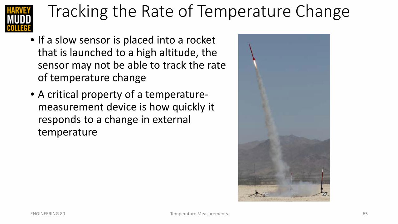
Tracking the Rate of Temperature Change• If a slow sensor is placed into a rocket
that is launched to a high altitude, the sensor may not be able to track the rate of temperature change
• A critical property of a temperature-measurement device is how quickly it responds to a change in external temperature
ENGINEERING 80 Temperature Measurements 65

Thermal System Step Response
ENGINEERING 80 Temperature Measurements 66

Thermal System Step Response
ENGINEERING 80 Temperature Measurements 67

Thermal System Step Response
ENGINEERING 80 Temperature Measurements 68

Thermal System Step Response
ENGINEERING 80 Temperature Measurements 69

Thermal System Step Response
ENGINEERING 80 Temperature Measurements 70
Thermal Time Constant
The thermal time constant can be measured as the time it
takes to get to (1/e) of the final temperature
100 (1-(1/e)) = 63 oC

Thermal System Step Response
ENGINEERING 80 Temperature Measurements 71
Thermal Time Constant
The thermal time constant can be measured as the time it
takes to get to (1/e) of the final temperature
100 (1-(1/e)) = 63 oC

Thermal System Step Response
ENGINEERING 80 Temperature Measurements 72
http://www.eng.hmc.edu/NewE80/PDFs/TemperatureMeasurementLecNotes.pdf
http://www.eng.hmc.edu/NewE80/PDFs/TemperatureMeasurementLecNotes.pdfhttp://www.colorado.edu/MCEN/Measlab/background1storder.pdf

SUMMARY
• Measuring Temperature• Types of Temperature Sensors
• Thermistor• Integrated Silicon Linear Sensor• Thermocouple• Resistive Temperature Detector (RTD)
• Choosing a Temperature Sensor• Calibrating Temperature Sensors• Thermal System Transient Response
ENGR 106 Lecture 3 Failure 73

References• Previous E80 Lectures and Lecture Notes
• http://www.eng.hmc.edu/NewE80/TemperatureLec.html
• Thermcouples White Paper• http://www.ohio.edu/people/bayless/seniorlab/thermocouple.pdf (downloaded 02/04/2015)
• University of Cambridge Thermoelectric Materials for Thermocouples• http://www.msm.cam.ac.uk/utc/thermocouple/pages/ThermocouplesOperatingPrinciples.html (viewed
02/04/2015)
• National Instruments Temperature Measurements with Thermocouples: How-To Guide• http://www.technologyreview.com/sites/default/files/legacy/temperature_measurements_with_therm
ocouples.pdf (downloaded 02/04/2015)
• Vishay NTCLE100E3104JB0 Data Sheet• http://www.eng.hmc.edu/NewE80/PDFs/VIshayThermDataSheet.pdf (downloaded on 02/04/2015)
ENGINEERING 80 Temperature Measurements 74