Embed Size (px)
Citation preview
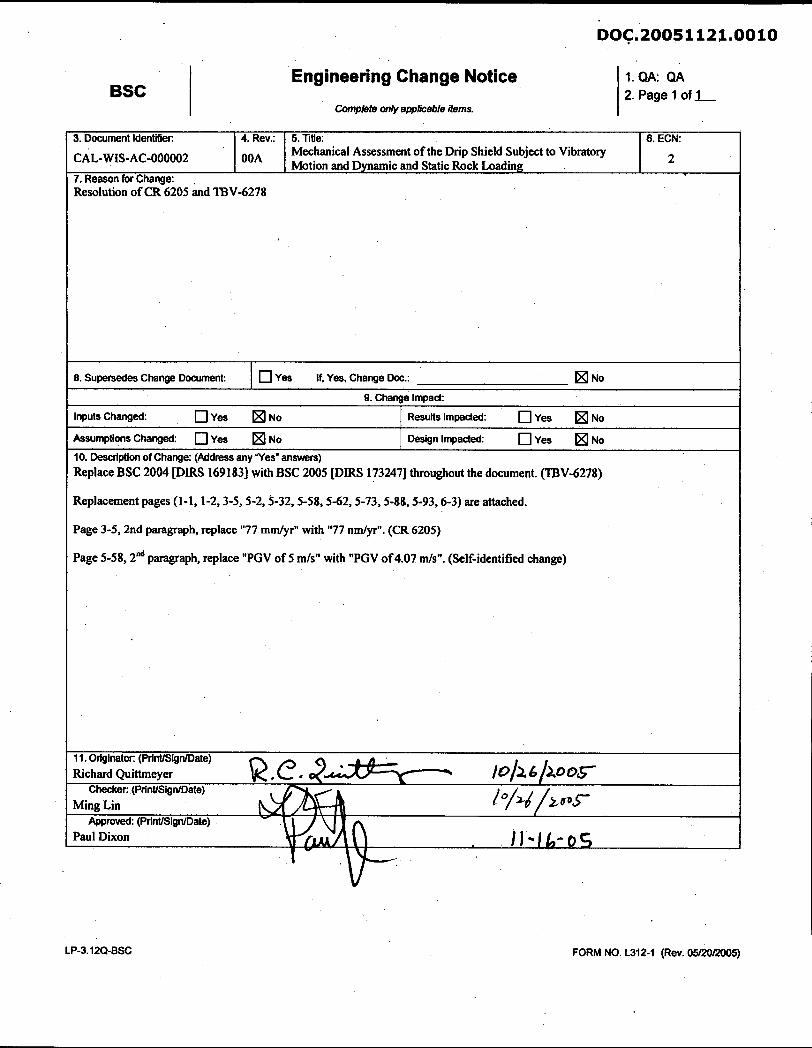
Engineering Change Notice
Compkte only applkable items.
1. QA: QA 2. Page 1 of 1
3. Document Identifier:
CAL-WIS-AC-000002
10. Description of Change: (Address any "Yes" answers) Replace BSC 2004 PIRS 1691831 with BSC 2005 [ D M 1732471 throughout the document. (TBV-6278)
8. SupeMd*r Change Document: I q Yes If, Yes. Change Doc.: IXI No
9. Change Impact:
I Replacement pages (1-l71-2,3-5,5-2,3-32,5-58,5-62,5-73,5-88,M3,6-3) are attached. I
7. Reason for Change: ,
Resolution of CR 6205 and TBV-6278
4. Rev.:
OOA
Inputs Changed: O ~ e s IXI NO
Assumptions Changed: q Yes No
Page 3-5,2nd paragraph, replace "77 mdyr" with "77 ndyr". (CR 6205) I
Results Impacted: q Yes IXI No
Design Impacted: q Yes No
I Page 5-58, 2d paragraph, replace "PGV of 5 mls" with "PGV of4.07 mls". (Self-identified change)
5. Title: Mechanical Assessment of the Drip Shield Subject to Vibratory Motion and Dynamic and Static Rock Loading
I I . Originator: (PrinUSignlDate) Richard Quittrneyer 4 lo/>
Checker (PrinUSignlDate) Ming Lin k & / h ~ ~
Approved: (PrinUSignIDate) Paul Dixon H * I ~ - O ~
6. ECN:
2
FORM NO. L312-I (Rev. 05/20/2005)
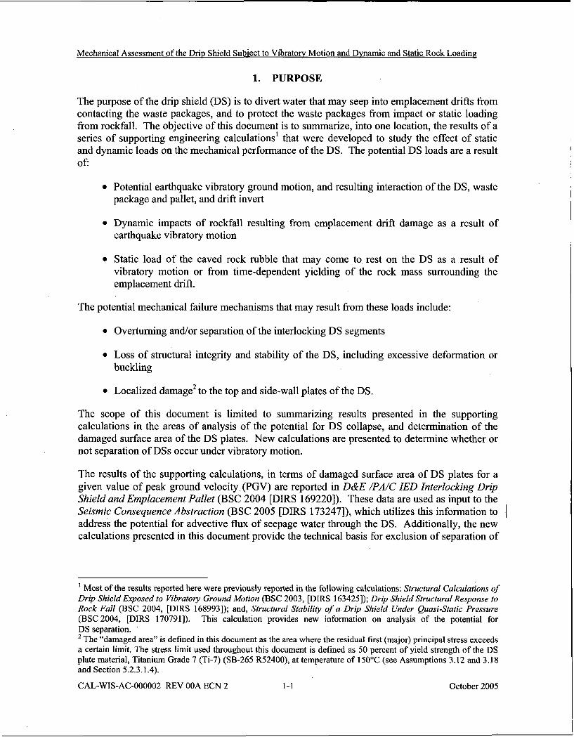
Mechanical Assessment of the Drip Shield Subiect to Vibratorv Motion and Dvnamic and Static Rock Loading
1. PURPOSE
The purpose of the drip shield (DS) is to divert water that may seep into emplacement drifts from contacting the waste packages, and to protect the waste packages from impact or static loading from rockfall. The objective of this document is to summarize, into one location, the results of a series of supporting engineering calculations1 that were developed to study the effect of static and dynamic loads on the mechanical performance of the DS. The potential DS loads are a result of:
Potential earthquake vibratory ground motion, and resulting interaction of the DS, waste package and pallet, and drift invert
Dynamic impacts of rockfall resulting from emplacement drift damage as a result of earthquake vibratory motion
Static load of the caved rock rubble that may come to rest on the DS as a result of vibratory motion or from time-dependent yielding of the rock mass surrounding the emplacement drift.
The potential mechanical failure mechanisms that may result from these loads include:
Overturning andlor separation of the interlocking DS segments
Loss of structural integrity and stability of the DS, including excessive deformation or buckling
Localized damage2 to the top and side-wall plates of the DS.
The scope of this document is limited to summarizing results presented in the supporting calculations in the areas of analysis of the potential for DS collapse, and determination of the damaged surface area of the DS plates. New calculations are presented to determine whether or not separation of DSs occur under vibratory motion.
The results of the supporting calculations, in terms of damaged surface area of DS plates for a given value of peak ground velocity (PGV) are reported in D&E /PA/C IED Interlocking Drip Shield and Emplacement Pallet (BSC 2004 [DIRS 1692201). These data are used as input to the Seismic Consequence Abstraction (BSC 2005 [DIRS 173247]), which utilizes this information to I address the potential for advective flux of seepage water through the DS. Additionally, the new calculations presented in this document provide the technical basis for exclusion of separation of
' Most of the results reported here were previously reported in the following calculations: Structural Calculations of Drip Shield Exposed to Vibratory Ground Motion (BSC 2003, [DIRS 1634251); Drip Shield Structural Response to Rock Fall (BSC 2004, [DIRS 1689931); and, Structural Stability of a Drip Shield Under Quasi-Static Pressure (BSC 2004, [DIRS 1707911). This calculation provides new information on analysis of the potential for DS separation.
The "damaged area" is defined in this document as the area where the residual first (major) principal stress exceeds a certain limit. The stress limit used throughout this document is defined as 50 percent of yield strength of the DS plate material, Titanium Grade 7 (Ti-7) (SB-265 R52400), at temperature of 150°C (see Assumptions 3.12 and 3.18 and Section 5.2.3.1.4).
CAL-WIS-AC-000002 REV OOA ECN 2 1-1 October 2005
Mechanical Assessment of the Drip Shield Subject to Vibratory Motion and Dvnamic and Static Rock Loading
DSs under vibratory ground motion from consideration in the Total System Performance Assessment-License Application (TSPA-LA). The exclusion arguments for DS separation are summarized in Features, Events, and Processes: Disruptive Events (BSC 2004 [DIRS 1700 171, Sections 6.2.1.5 and 6.2.1.3) (FEP 1.2.03.02.0A - Seismic Ground Motion Damages EBS Components) and the Seismic Consequence Abstraction (BSC 2005 [DIRS 1732471, Sections 6.5.4 and 6.5.5). The Seismic Consequence Abstraction subsequently provides the abstraction for the seismic scenario class used in support of the Total System Performance Assessment-License Application (TSPA-LA).
This document is prepared in accordance with the applicable technical work plan: Technical , Work Plan For: Regulatory Integration Modeling of Drift Degradation, Waste Package and Drip Shield Vibratory Motion and Seismic Consequences (BSC 2004 [DIRS 171520]), which directs the work identified in work package ARTMO5. The technical work plan was prepared in accordance with AP-2.27Q, Planning for Science Activities. This calculation was performed under the Repository Integration Project, in cooperation with the Waste Package and Components group of Design and Engineering. This document was developed in conformance with procedure AP-3.12Q, Design Calculations and Analyses. The DS is classified as a Safety Category item (BSC 2004 [DIRS 1683611, p. A-5). Therefore, this calculation is subject to the Quality Assurance Requirements and Description (DOE 2004 [DIRS 171 5391).
The DS design considered in the calculations summarized in this document is not presented in detail. Design drawings and material specifications can be found in D&E / PA/C ZED Interlocking Drip Shield and Emplacement Pallet (BSC 2004 [DIRS 1692201) as well as in the calculations that support this summary document (BSC 2003 [DIRS 1634251; BSC 2004 [DIRS 1689931 and BSC 2004 [DIRS 1707911). The dimensions and materials for the design of the 2 1 -PWR (pressurized water reactor) waste package and emplacement pallet (pallet, for brevity, throughout the document) used in this calculation are also provided in Emplacement Pallet (BSC 2003 [DIRS 1615201) and D&E/PA/C ZED Typical Waste Package Components Assembly (BSC 2004 [DIRS 1694721). The 21-PWR waste package was used as a basis for the calculations summarized in this document since it is the most commonly-occurring of the various waste package designs. More than 38 percent of all waste packages are 21-PWR waste packages, and the second most frequent design, the 44-boiling water reactor waste package (approximately 26 percent), has similar dimensions and mass as the 21-PWR waste package (BSC 2004 [DIRS 1694721, Table 1 1).
CAL-WIS-AC-000002 REV OOA ECN 2 October 2005
Mechanical Assessment of the Drip Shield Subject to Vibratorv Motion and Dvnamic and Static Rock Loading
impact of thermohydrologic parameters on the in-drift environment (BSC 2004 [DIRS 1695651, Section 6.3.7 and Table 6.3-8). The results show that the peak waste package temperature in a collapsed drift for the base case thermal conductivity of the rubble is greater than 200°C for a very brief period of time - less than 100 years - and the waste package temperature drops below 150°C within approximately 350 years after collapse, even for the "hottest" waste package considered in the parameter study. These results are for the case of a collapse occurring coincident with the closure of the repository. It follows that 150°C is a reasonable and conservative value for evaluation of material properties in a collapsed drift over 96.5 percent of the regulatory period. This assumption is used in Sections 1 and 5.2.3.
3.13 The thickness of the Ti-7 and Ti-24 plates are reduced by 2 mm. For Ti-7, this thickness reduction results from using the 95th percentile general corrosion rate values used in TSPA-LA for both sides of the titanium plate (BSC 2004 [DIRS 1698451, Section 6.5.5; DTN: MOO408MWDGLCDS.002 [DIRS 1714861). For the outside and inside plates, the 95th percentile general corrosion rate values (a reasonably conservative estimate) are 1.12E-4 mmlyr and 8.59E-5 m d y r , respectively. Therefore in 10,000 years, about 1.12 mm is removed from the outer surface by general corrosion and about 0.86 mm are removed from the inner surface (i.e., a total loss of about 2 mm of thickness). Alternatively, the highest measured general corrosion rate from the 5-year exposed Ti samples used for validation of the TSPA-LA general corrosion distributions is 7 7 n d y r (BSC 2004 [DIRS 1698451, Table 23; 1 DTN: M00408MWDGLCDS.002 [DIRS 17 14861). Using this value for both sides of the drip shield, a total loss of about 1.54 mm of thickness can be calculated over an exposure period of 10,000 years. Therefore, a thickness reduction of 2 mm is a reasonable estimate of the total thickness loss for Ti-7 due to general corrosion in 10,000 years. For Ti-24, the thickness reduction over a 10,000 year period was determined to be about 0.75 mm per exposed surface in the Aqueous Corrosion Rates for Waste Package Materials report (BSC 2004 [DIRS 1699821, Section 6.5.2). Therefore, a thickness reduction of 2 mm is a reasonable estimate of the total thickness loss for Ti-24 due to general corrosion in 10,000 years.
3.14 The rock shape is assumed to be a rectangular prism. The rationale for this assumption is that the rock block data (BSC 2004 [DIRS 1685501) show that some of the rock blocks are essentially rectangular prism. An FE representation of the rock with an inclined rectangular prism provides a conservative approach from the perspective that the rock center of gravity and the point of impact are on the line parallel with direction of the impact, transferring the maximum linear momentum to the DS. Impact by the sharp edge of the prism also results in maximum strain on the DS plate. The vertex coordinates of the prism are obtained from DTN: M00301MWD3DE27.003 (Block Geometry Information.doc) in order to calculate the enveloping dimensions (DTN: MOO30 1 MWD3DE27.003 provides details). This
CAL-WIS-AC-000002 REV OOA ECN 2 3 -5 October 2005
Mechanical Assessment of the Drir, Shield Subiect to Vibratory Motion and Dvnamic and Static Rock Loading
The DS is a free-standing structure, constructed of titanium bulkheads and overlying sheets,. whose legs rest on the invert of the tunnel. The invert is constructed of carbon steel beams with crushed tuff compacted between them. Initially the weight of the DS is borne by the steel beams. As corrosion of these beams occurs over time, the weight will be transferred to the compacted, crushed tuff invert. The purpose of the DS is to prevent direct seepage of water on the waste packages, and to protect the waste packages from direct impacts by rockfall (illustrated in Figure 5-1). Specifically, effectiveness of the DS could be affected by the following mechanical processes:
Relatively large rigid-body displacements of the DSs that would overturn the DS or create a gap between the neighboring DSs (The DSs are designed to overlap each other creating a continuous shielded area underneath them. This potential separation is an important consideration because it impacts the function of the DS as a flow and rockfall barrier.)
Loss of structural integrity due to mechanical collapse or buckling of the main structural elements (e.g., the support beam and the bulkhead)
Puncture, tearing or damage that would accelerate the stress corrosion rate of the DS plates (other corrosion mechanisms are accounted for in the calculation by a uniform thickness reduction of the DS as discussed in Assumption 3.13 and Section 5.2.3.1.5).
The DS could be subjected to static and dynamic loads during the postclosure period. Static load that could potentially have an effect on structural integrity of the DS is due to the weight of caved rock rubble that may rest on the top of the DS or between the DS and the walls of the emplacement drift. Emplacement drift failure, and resulting caving and expansion of the tunnel profile can .occur as a result of thermally induced stresses, seismic loading, time-dependent strength degradation, or different combinations of these factors. The dynamic loads on the DS, which are primarily due to the seismic ground motion, include inertial forces and impacts of the falling rock blocks. The inertial forces can result in motion of the DSs relative to each other, and relative to the drift walls and other objects inside the drift (e.g., the waste packages and pallet). Consequently, inertial forces can cause separation of the DSs and impact to other DSs and objects inside the emplacement drifts. The impacts of the falling blocks can take place during seismic ground motion and as a result of drift degradation due to time-dependent strength loss.
The calculations summarized in this document determine potential for separation of the DSs and loss of the structural integrity and stability, but also the damaged areas on the DS (i.e., those areas that exceed the residual stress threshold for Ti-7) from impacts between the DS and the waste package, pallet, invert, drift wall, and by rockfall. The damaged area estimates to the DS surface plates as a function of peak ground velocity (PGV) are used as input to the Seismic Consequence Abstraction (BSC 2005 [DIRS 173247]), which provides damage abstractions to the TSPA-LA. In the Seismic Consequence Abstraction (BSC 2005 [DIRS 173247]), the physical interpretation of the damaged areas is a resulting network of stress corrosion cracks through which seepage water could potentially pass to the waste package. A discussion of the physical morphology of the stress corrosion cracks, and the potential for advective flux through the DS is provided in the Seismic Consequence Abstraction (BSC 2005 [DIRS 1732471).
CAL-WIS-AC-000002 REV OOA ECN 2 5 -2 October 2005
Mechanical Assessment of the Driv Shield Subiect to Vibratorv Motion and Dvnamic and Static Rock Loading
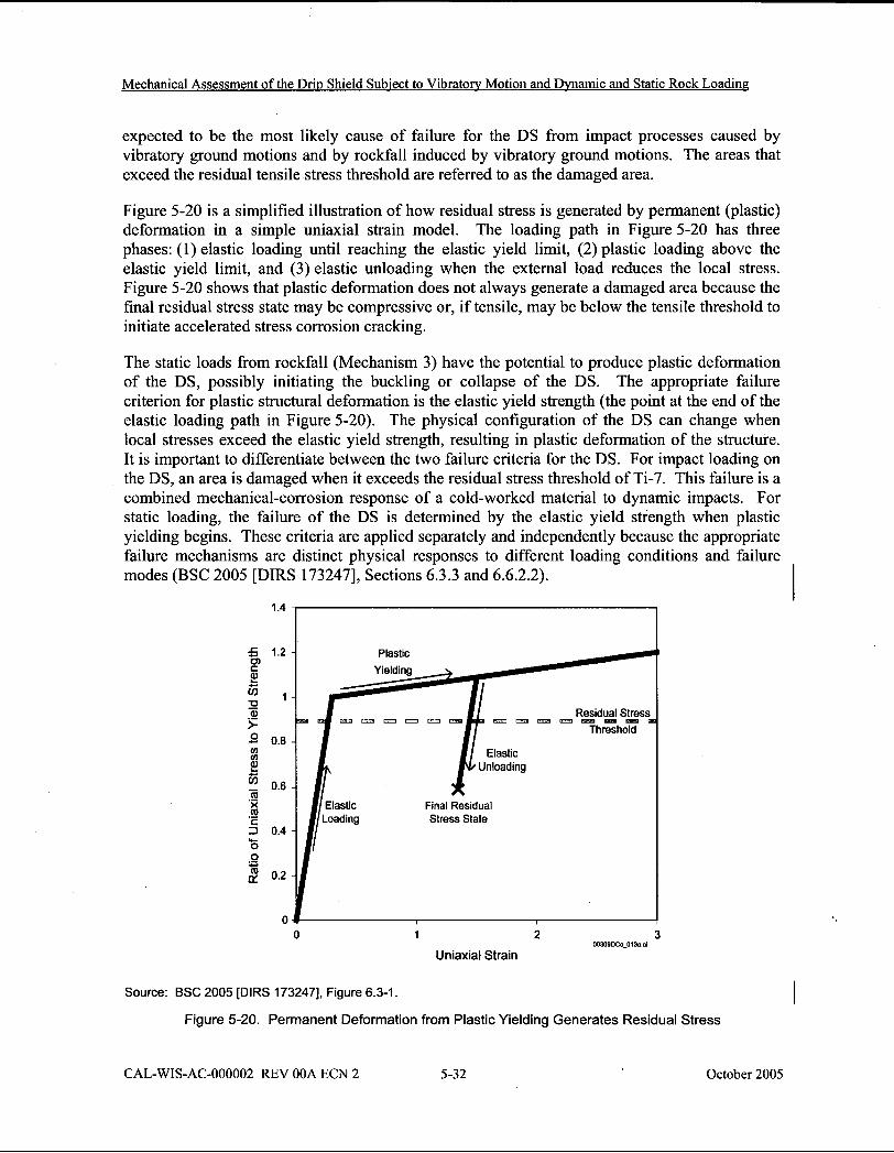
expected to be the most likely cause of failure for the DS from impact processes caused by vibratory ground motions and by rockfall induced by vibratory ground motions. The areas that exceed the residual tensile stress threshold are referred to as the damaged area.
Figure 5-20 is a simplified illustration of how residual stress is generated by permanent (plastic) deformation in a simple uniaxial strain model. The loading path in Figure 5-20 has three phases: (I) elastic loading until reaching the elastic yield limit, (2) plastic loading above the elastic yield limit, and (3) elastic unloading when the external load reduces the local stress. Figure 5-20 shows that plastic deformation does not always generate a damaged area because the final residual stress state may be compressive or, if tensile, may be below the tensile threshold to initiate accelerated stress corrosion cracking.
The static loads from rockfall (Mechanism 3) have the potential to produce plastic deformation of the DS, possibly initiating the buckling or collapse of the DS. The appropriate failure criterion for plastic structural deformation is the elastic yield strength (the point at the end of the elastic loading path in Figure 5-20). The physical configuration of the DS can change when local stresses exceed the elastic yield strength, resulting in plastic deformation of the structure. It is important to differentiate between the two failure criteria for the DS. For impact loading on the DS, an area is damaged when it exceeds the residual stress threshold of Ti-7. This failure is a combined mechanical-corrosion response of a cold-worked material to dynamic impacts. For static loading, the failure of the DS is determined by the elastic yield strength when plastic yielding begins. These criteria are applied separately and independently because the appropriate failure mechanisms are distinct physical responses to different loading conditions and failure modes (BSC 2005 [DIRS 1732471, Sections 6.3.3 and 6.6.2.2).
5 1.2 2 2 fj 1 = Q) s 3 0.8 V) ul 2 +
11 0.6 m .- X m .- c 3 0.4 w- 0 0 .- C 2 0.2
0 0 1 2
W389DCc_013a a# 3
Uniaxial Strain
Source: BSC 2005 [DIRS 1732471, Figure 6.3-1.
Figure 5-20. Permanent Deformation from Plastic Yielding Generates Residual Stress
I
CAL-WIS-AC-000002 REV OOA ECN 2 5-32 October 2005
Mechanical Assessment of the Drip Shield Subject to Vibratory Motion and Dvnamic and Static Rock Loading
5.3.1.1.2 Description of the Kinematic Simulations
A sensitivity study was conducted to investigate the effects of various parameters on the potential for DS separation under vibratory motion. These parameters include:
The number of DSs Friction coefficients Contact stiffnesses Ground motions Parameters that characterize interaction with the collapsed rock mass rubble.
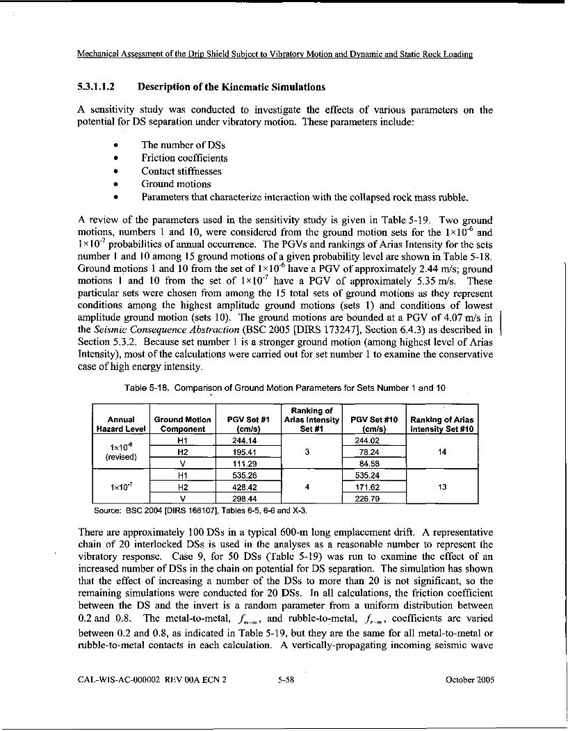
A review of the parameters used in the sensitivity study is given in Table 5-19. Two ground motions, numbers 1 and 10, were considered from the ground motion sets for the 1x10-~ and 1 x probabilities of annual occurrence. The PGVs and rankings of Arias Intensity for the sets number 1 and 10 among 15 ground motions of a given probability level are shown in Table 5-1 8. Ground motions 1 and 10 from the set of 1 x 10 '~ have a PGV of approximately 2.44 d s ; ground motions 1' and 10 from the set of 1x10.~ have a PGV of approximately 5.35 d s . These particular sets were chosen from among the 15 total sets of ground motions as they represent conditions among the highest amplitude ground motions (sets 1) and conditions of lowest amplitude ground motion (sets 10). The ground motions are bounded at a PGV of 4.07 mls in the Seismic Consequence Abstraction (BSC 2005 [DIRS 1732471, Section 6.4.3) as described in Section 5.3.2. Because set number 1 is a stronger ground motion (among highest level of Arias Intensity), most of the calculations were carried out for set number 1 to examine the conservative case of high energy intensity.
Table 5-1 8. Comparison of Ground Motion Parameters for Sets Number 1 and 10
Source: BSC 2004 [DIRS 1661071, Tables 6-5,6-6 and X-3.
Annual Hazard Level
1x10⁶ (revised)
1 XI 0-'
There are approximately 100 DSs in a typical 600-m long emplacement drift. A representative chain of 20 interlocked DSs is used in the analyses as a reasonable number to represent the vibratory response. Case 9, for 50 DSs (Table 5-19) was run to examine the effect of an increased number of DSs in the chain on potential for DS separation. The simulation has shown that the effect of increasing a number of the DSs to more than 20 is not significant, so the remaining simulations were conducted for 20 DSs. In all calculations, the friction coefficient between the DS and the invert is a random parameter from a uniform distribution between 0.2 and 0.8. The metal-to-metal, fm-m, and rubble-to-metal, f,-, , coefficients are varied between 0.2 and 0.8, as indicated in Table 5-19, but they are the same for all metal-to-metal or rubble-to-metal contacts in each calculation. A vertically-propagating incoming seismic wave
CAL-WIS-AC-000002 REV OOA ECN 2 5-58 October 2005
Ground Motion Component
H I H2 V H I H2 V
PGV Set # I (cmls)
244.14 195.41 111.29 535.26 428.42 298.44
Ranking of Arias Intensity
Set # I
3
4
PGV Set #I0 (cmls)
244.02 78.24 84.58
535.24 171.62 226.79
Ranking of Arias Intensity Set #I0
14
13
Mechanical Assessment of the Drip Shield Subiect to Vibratory Motion and Dynamic and Static Rock Loading
The structural calculations of the interlocking DS's exposed to the vibratory ground motion have many complexities inherent in the nature of the problem, including the following:
The externally applied loads (i.e., the ground motion time histories) are extremely intense. This causes a variety of numerical issues at 1 x level and particularly at 1 x 1 o ' ~ level12.
The phenomena are highly nonlinear. Momentum is transferred among the repository emplacement drift and unanchored repository components (DS and waste package pallet assembly) solely by friction and impact. Geometrical nonlinearity (large deformations) is coupled with nonlinear constitutive behavior of the materials (elastoplastic behavior with kinematic hardening).
Capturing both the large-scale kinematics- and the occasional small-scale deformations . (i.e., localized impacts) imposes extremely difficult FE meshing requirements.
The extraordinary meshing requirements are, together with the intensity of ground motion, responsible for the very small time step required for numerical stability (approximately a microsecond, depending on annual frequency of occurrence and particular ground-motion time history). The very small time step is, in turn, necessary for simulation of a long-duration event (-30-40 s).
These complexities impose extreme computational requirements. Consequently, it is necessary to simplify the representation, but retain important features of the problem. The two most important simplifications are: 1) use of shell elements for representation of not only the DS plates but also some of the support structure, and 2) representation of the waste package and pallet as a single entity (waste package pallet assembly). These are discussed in the following sections.
121t is noted that the ground motion time histories used in this calculation were determined from a Probabilistic Seismic Hazard Assessment (PSHA) expert elicitation in which the aleatory variability in ground motion was described using unbounded lognormal distributions. As the PSHA calculations are extended to lower and lower annual probabilities of exceedence, the mean ground motions increase without bound, eventually reaching levels that are not credible. These levels of ground motion are not credible in that they eventually result in seismic strains that would cause the rock mass (in absence of any excavation) to fail through formation of fractures, an effect that is not observed at Yucca Mountain. An analysis, presented in Peak Ground Velocities for Seismic Events at Yucca I Mountain, Nevada (BSC 2004 [DIRS 1701371) estimates an upper bound to the ground motions at the Yucca Mountain site based on the shear strain increments (relative to the in situ stress state) required to damage (fracture) the repository rock mass. Such seismic-induced fractures are not observed in excavations at the Yucca Mountain site in repository host rocks that were erupted and cooled some 12.8 million years ago (BSC 2004 [DIRS 1701371). Based on these observations, a reasonable bound for horizontal PGV with an annual frequency of exceedance of
is about 4 d s . This is less than the 5.35 d s PGV used in the present calculations for the 1x10'~ annual exceedance probability seismic event. Even though bounding peak ground velocities have been estimated, they have not been used explicitly in the calculations of seismic damage performed in the supporting calculations and summarized in this document. In other words, damage has been assessed for time histories with PGVs in excess of the bounding values defined in Peak Ground Velocities for Seismic Events at Yucca Mountain, Nevada (BSC 2004 [DIRS 1701371. Instead, the damage to EBS components is bounded within the Seismic Consequence Abstraction - i.e., damage associated with PGVs in excess of about 4 rnls is bounded at the 4 mls level (BSC 2005 [DIRS 1732471, Section 6.4.3).
CAL-WIS-AC-000002 REV OOA ECN 2 5-62 October 2005
Mechanical Assessment o f the Drip Shield Subject to Vibratory Motion and Dvnamic and Static Rock Loading
5.4.4 Use of Drip Shield Structural Analysis in the Seismic Scenario
5.4.4.1 Feeds of Drip Shield Structural Analysis to the Seismic Consequence Abstraction
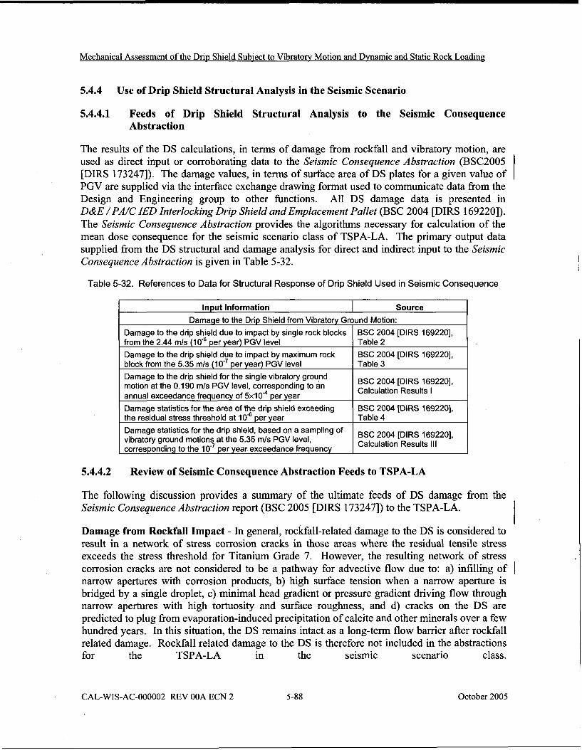
The results of the DS calculations, in terms of damage from rockfall and vibratory motion, are used as direct input or corroborating data to the Seismic Consequence Abstraction (BSC2005 [DIRS 1732471). The damage values, in terms of surface area of DS plates for a given value of PGV are supplied via the interface exchange drawing format used to communicate data fi-om the Design and Engineering group to other functions. All DS damage data is presented in D&E / PA/C IED Interlocking Drip Shield and Emplacement Pallet (BSC 2004 [DIRS 1692201). The Seismic Consequence Abstraction provides the algorithms necessary for calculation of the mean dose consequence for the seismic scenario class of TSPA-LA. The primary output data supplied from the DS structural and damage analysis for direct and indirect input to the Seismic Consequence Abstraction is given in Table 5-32.
Table 5-32. References to Data for Structural Response of Drip Shield Used in Seismic Consequence
5.4.4.2 Review of Seismic Consequence Abstraction Feeds to TSPA-LA
Input Information
The following discussion provides a summary of the ultimate feeds of DS damage fi-om the Seismic Consequence Abstraction report (BSC 2005 [DIRS 1732471) to the TSPA-LA.
Source
Damage from Rockfall Impact - In general, rockfall-related damage to the DS is considered to result in a network of stress corrosion cracks in those areas where the residual tensile stress exceeds the stress threshold for Titanium Grade 7. However, the resulting network of stress corrosion cracks are not considered to be a pathway for advective flow due to: a) infilling of I narrow apertures with corrosion products, b) high surface tension when a narrow aperture is bridged by a single droplet, c) minimal head gradient or pressure gradient driving flow through narrow apertures with high tortuosity and surface roughness, and d) cracks on the DS are predicted to plug from evaporation-induced precipitation of calcite and other minerals over a few hundred years. In this situation, the DS remains intact as a long-term flow barrier after rockfall related damage. Rockfall related damage to the DS is therefore not included in the abstractions for the TSPA-LA in the seismic scenario class.
CAL-WIS-AC-000002 REV OOA ECN 2 5-88 October 2005
Damage to the Drip Shield from Vibratory Ground Motion:
Damage to the drip shield due to impact by single rock blocks from the 2.44 mls (lo4 per year) PGV level
Damage to the drip shield due to impact by maximum rock block from the 5.35 mls per year) PGV level
Damage to the drip shield for the single vibratory ground motion at the 0.190 mls PGV level, corresponding to an annual exceedance frequency of 5 x 1 0 ~ per year
Damage statistics for the area of the drip shield exceeding the residual stress threshold at l o4 per year
Damage statistics for the drip shield, based on a sampling of vibratory ground motions at the 5.35 mls PGV level, corresponding to the per year exceedance frequency
BSC 2004 [DIRS 1692201, Table 2
BSC 2004 [DIRS 1692201, Table 3
BSC 2004 [DIRS 1692201, Calculation Results I
BSC 2004 [DIRS 1692201, Table 4
BSC 2004 [DIRS 1692201, Calculation Results Ill
Mechanical Assessment of the Drip Shield Subiect to Vibratory Motion and DNamic and Static Rock Loading
the document. Appropriate alternative models are used for analyses, including the use of discontinuurn, kinematic approach as well as more sophisticated three-dimensional finite element analysis are used for examination of vibratory motion. Model uncertainties are propagated through damage estimates and structural stability calculations that provide input to the Seismic consequence Abstraction (BSC 2005 [DIRS 173247]), which eventually ( provides input to the TSPA-LA.
CAL-WIS-AC-000002 REV OOA ECN 2 5-93 October 2005
Mechanical Assessment of the Driv Shield Subject to Vibratory Motion and Dwamic and Static Rock Loading
BSC 2004. Peak Ground Velocities for Seismic Events at Yucca Mountain, Nevada. 170137 ANL-MGR-GS-000004 REV 000A. Las Vegas, Nevada: Bechtel SAIC Company. ACC: TBV: 6278.
BSC 2004. Q-List. 000-30R-MGRO-00500-000-000 REV 00. Las Vegas, Nevada: 168361 Bechtel SAIC Company. ACC: ENG.2004072 1.0007.
BSC 2004. Repository Subsurface Emplacement Drifts Steel Invert Structure Sect. & 169776 Committed Materials. 800-SSO-SSEO-00102-000-00B. Las Vegas, Nevada: Bechtel SAIC Company. ACC: ENG.20040520.0005.
BSC 2004. Sampling of Stochastic Input Parameters for Roci$all Calculations and for Structural Response Calculations Under Vibratory Ground Motion. ANL-EBS-PA-000009 REV 01. Las Vegas, Nevada: Bechtel SAIC Company. ACC: DOC.20040901.0004.
BSC 2005. Seismic Consequence Abstraction. MDL-WIS-PA-000003 REV 02. Las Vegas, Nevada: Bechtel SAIC Company. ACC: DOC.20050829.0005.
BSC 2004. Stress Corrosion Cracking of the Drip Shield, the Waste Package Outer Barrier, and the Stainless Steel Structural Material. ANL-EBS-MD-000005 REV 0 1 ICN 01. Las Vegas, Nevada: Bechtel SAIC Company. ACC: DOC.200403 18.0010.
BSC 2004. Technical Work Plan for: Regulatory Integration Modeling of Drift Degradation, Waste Package and Drip Shield Vibratory Motion and Seismic Consequences. TWP-MGR-GS-000003 REV 00 ICN 01. Las Vegas, Nevada: Bechtel SAIC Company. ACC: DOC.200408 10.0003.
BSC 2004. Structural Stability of a Drip Shield under Quasi-Static Pressure. 000-00C-SSEO-00500-000-00Aa. Las Vegas, Nevada: Bechtel SAIC Company. ACC: ENG.20040830.0032.
Chen, W.F. 1982. Plasticity in Reinforced Concrete. New York, New York: McGraw-Hill Book Company. TIC: 240453.
Cikanek, E.M.; Grant, T.A.; and Blakely, R.J. 2004. Data Qualification and Data Summary Report: Intact Rock Properties Data on Uniaxial Compressive Strength, Triaxial Compressive Strength, Friction Angle, and Cohesion, with Errata. TDR-MGR-GE-000003 REV 00 Errata 4. Las Vegas, Nevada: Bechtel SAIC Company. ACC: DOC.200302 14.0007; DOC.2003 1007.0004; DOC.2003 1 105.0007; DOC.20040506.0003; DOC.200405 14.0003.
DeGrassi, G., 1992. Review of the Technical Basis and Verijication of Current Analysis Methods Used to Predict Seismic Response of Spent Nuclear Fuel Racks. NUREGICR-5912. Washington, DC: U.S. Nuclear Regulatory Commission. TIC: 253724.
CAL-WIS-AC-000002 REV OOA ECN 2 6-3 October 2005