Embed Size (px)
Citation preview

CITY OF NORMANNorman, Oklahoma
forStreets
Storm DrainageWater Lines
Sanitary Sewers
ENGINEERING DESIGNCRITERIA
Adopted: September 24, 1996Amendment No.1: April 28, 1998Amendment No.2: March 28, 2000
Amendment No.3: May 8, 2001Amendment No. 4: July 24, 2001
Amendment No. 5: February 26, 2002Amendment No. 6: September 9, 2003Amendment No. 7: January 11, 2005Amendment No. 8a: June 13, 2006
Amendment No. 8b: July 11, 2006

Cover Sheet
Blank Page

City of Norman ENGINEERING DESIGN CRITERIA
TABLE OF CONTENTS
INTRODUCTION
Page No. 1000 GENERAL
1001 Standards and Specifications .......................................................................... 1000 - 1 1002 Drafting ......................................................................................................... 1000 - 1 1003 Bench Marks................................................................................................... 1000 - 3 1004 Site Grading Plan............................................................................................ 1000 - 4 1005 Earth Change Permit....................................................................................... 1000 - 5 1006 Rural Requirements ....................................................................................... 1000 - 5 1007 Abbreviations and Definitions........................................................................ 1000 - 5 1008 Retaining Wall Design ................................................................................... 1000 - 5 1009 Solid Waste Container Enclosure ................................................................... 1000 - 5 1010 Encroachment of Public Property................................................................... 1000 - 6 1011 Permanent Encroachments ............................................................................. 1000 - 6
2000 WATER MAINS
2001 General Requirements .................................................................................... 2000 - 1 2002 Municipal Service Area .................................................................................. 2000 - 1 2003 Rural Service Area ......................................................................................... 2000 - 4
3000 SANITARY SEWER
3001 General Requirements .................................................................................... 3000 - 1 3002 Sewer Lines .................................................................................................... 3000 - 1 3003 Manholes ........................................................................................................ 3000 - 3 3004 Connections .................................................................................................... 3000 - 4 3005 Waste Stabilization Lagoons .......................................................................... 3000 - 4
4000 STREETS
4001 General Requirements .................................................................................... 4000 - 1 4002 Plan Sheets and Profiles ................................................................................. 4000 - 1 4003 Street Functional Classification...................................................................... 4000 - 2 4004 Streets ............................................................................................................. 4000 - 4 4005 Intersection Design, Site Triangles................................................................. 4000 - 5 4006 Traffic Impact of Developments..................................................................... 4000 - 7 4007 Typical Sections ............................................................................................. 4000 - 8 4008 Cross Sections ................................................................................................ 4000 - 9 4009 Structures and Specific Details....................................................................... 4000 - 9 4010 Sidewalks...................................................................................................... 4000 - 10 4011 Driveway Approach Standards..................................................................... 4000 - 11 4012 Signage ......................................................................................................... 4000 - 14 4013 Striping ......................................................................................................... 4000 - 15 4014 Easement and Right-of-Way ........................................................................ 4000 - 15 4015 Paving Design............................................................................................... 4000 - 15 4016 Lighting ........................................................................................................ 4000 - 18 4017 Cut Back Parking on Public Right-of-Way .................................................. 4000 - 19 4018 Arterial Access ............................................................................................. 4000 - 20
i

Page No. 5000 STORM WATER
5001 General Requirements .................................................................................... 5000 - 1 5002 Easements ....................................................................................................... 5000 - 2 5003 Drainage Systems Requirement...................................................................... 5000 - 2 5004 Rainfall ........................................................................................................... 5000 - 4 5005 Runoff............................................................................................................. 5000 - 4 5006 Street Drainage ............................................................................................... 5000 - 9 5007 Storm Sewer Inlets ....................................................................................... 5000 - 11 5008 Storm Sewer Pipe ......................................................................................... 5000 - 12 5009 Open Channels.............................................................................................. 5000 - 17 5010 Hydraulic Structures..................................................................................... 5000 - 21 5011 Storage and Infiltration................................................................................. 5000 - 24 5012 Erosion and Sediment Control......................................................................5000 – 27
6000 STORM WATER POLLUTION 6001 Purpose ........................................................................................................... 6000 - 1 6002 Definitions ...................................................................................................... 6000 - 1 6003 Regulations ..................................................................................................... 6000 - 2 6004 Compliance..................................................................................................... 6000 - 5
ii

City of Norman ENGINEERING DESIGN CRITERIA INTRODUCTION
The Engineering Design Criteria, together with the City of Norman's Standard Specifications and Construction Drawings regulate both public improvements and private work which will either be dedicated to or accepted by the City. In addition, all work within the public right-of-way is governed by these regulations. They are intended to provide for coordinated development with adequate facilities to serve and protect the users. These documents are meant to provide minimum criteria and to apply rigidly to new developments which are not constrained by already existing improvements. Designers are encouraged to exceed these criteria whenever possible to provide better engineered facilities. Infill development in an urban area is often constrained when matching existing improvements. To the extent deemed possible by the City Engineer, infill developments shall be completed in accordance with this Engineering Design Criteria document. The City Engineer however, may allow modification of these requirements when necessary to allow private and public construction which is compatible with surrounding in-place improvements. These design criteria, standard specifications and construction standards shall also be used in conjunction with the City's zoning regulations and subdivision ordinances for site development work on private property. These documents, Engineering Design Criteria and Standard Specifications and Construction Drawings, were adopted by the City of Norman City Council on September 24, 1996, and adopted revisions on April 28, 1998; March 28, 2000; May 8, 2001; July 24, 2001; February 26, 2002; September 9, 2003; January 11, 2005; June 13, 2006; and July 11, 2006.
iii

Blank Page
iv

City of Norman ENGINEERING DESIGN CRITERIA SECTION 1000 GENERAL
1001 STANDARDS AND SPECIFICATIONS
1001.1 All plans will be reviewed to see how they will affect future site and adjacent area development and how future site development will affect the City and City operated facilities.
1001.2 Whenever a Design Engineer wishes to change from the minimum criteria, the Engineer shall submit the proposed changes and justification to the City Engineer for review.
1001.3 Any work not covered by the adopted design criteria standard specifications of the City of Norman, the Consulting Engineer shall include two copies of the design, specifications and/or special provision with his first submittal for review and acceptance by the City Engineer.
1001.4 Review and acceptance of plans by the City Engineer does not release the Consulting Engineer, Architect, or Contractor from his professional responsibility to meet the planning and design objectives of the project as required by good engineering practice and the City of Norman. The Contractor must keep a set of approved construction plans on the job site at all times.
1001.5 The plan cover sheet and the calculation report shall be signed, sealed and dated by a Professional Engineer, registered in the State of Oklahoma, prior to submitting the plans to the City Engineer's office for review.
1001.6 Construction pay items and Engineer's cost estimate for each item of work covered by the standard specifications and/or special provisions shall be increased to the next unit and the method of measurement clearly listed in the proposal as the basis for payment.
1001.7 Arterial streets of widths greater than 15.8m (52') and/or other special streets which do not conform to the City's standard Construction Drawings shall be reviewed and accepted by the City Engineer.
1002 DRAFTING
1002.1 Construction plans shall be drawn on an acceptable transparent reproducible medium.
1002.2 Standard sheets shall be 564 mm x 800 mm (22" x 34") having a margin of 50 mm (1.5") along the left border and 15 mm (0.5") along the top, bottom and right borders.
1002. 3 All project drawing packages shall have a cover sheet containing the project title, project location with location map, project owner's name, address, telephone number and contact person if not the owner, Engineer's name, address, and telephone number, drawing index and legend. The cover sheet shall not be used for a plan sheet. The package must also include an overall plan sheet showing proposed improvements with sufficient labeling for reference to plan and/or profile sheets.
1002.4 North shall be oriented to the top or right hand side of all plan sheets.
1002.5 A Title Block shall be located in the lower right hand corner of each sheet and shall include the project title, Owner's and Engineer's name, drawing description, page number and date.
1002.6 The scale shall not be less than 1:500 (1" = 50') horizontal and 1:50 (1" = 5') vertical on plan and profile sheets. Minimum scale shall be 1:1000 (1" = 100') on plan sheets. Larger scales may be required where conditions warrant.
1000 - 1
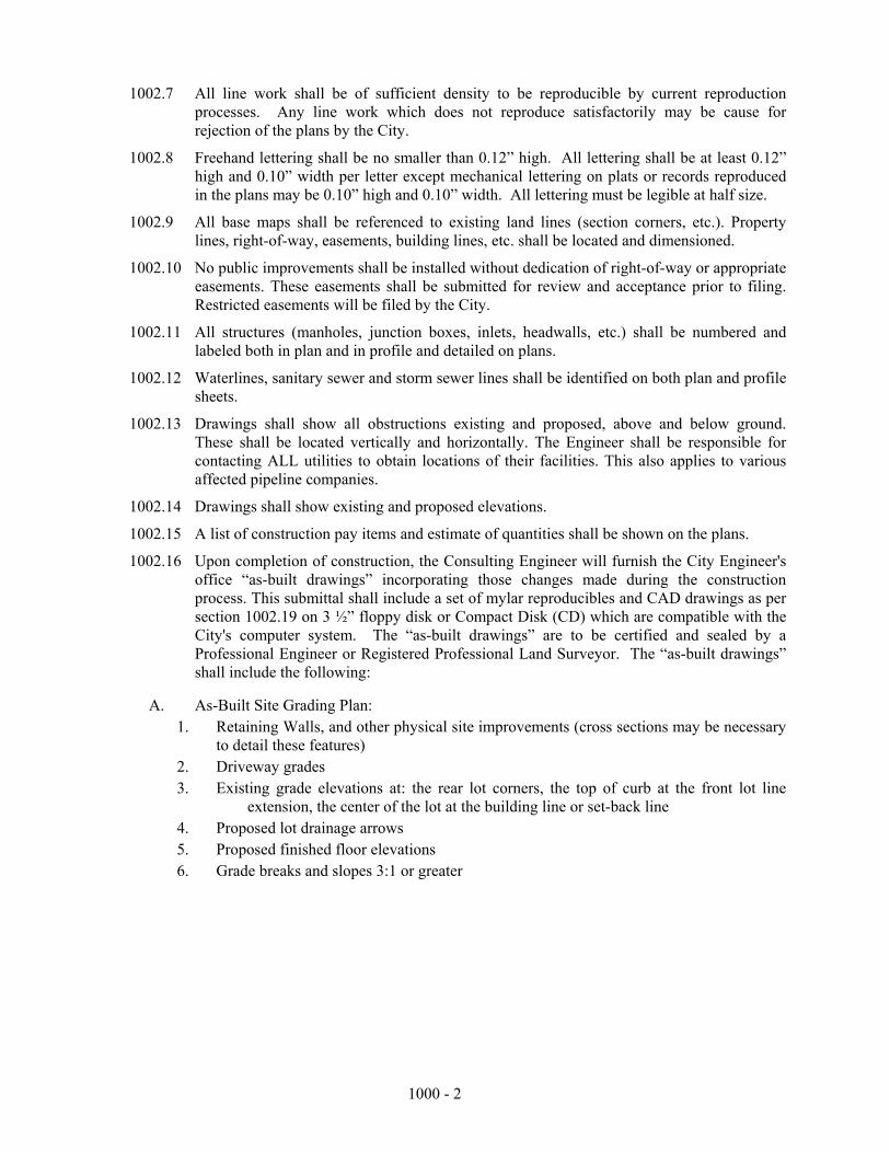
1002.7 All line work shall be of sufficient density to be reproducible by current reproduction processes. Any line work which does not reproduce satisfactorily may be cause for rejection of the plans by the City.
1002.8 Freehand lettering shall be no smaller than 0.12” high. All lettering shall be at least 0.12” high and 0.10” width per letter except mechanical lettering on plats or records reproduced in the plans may be 0.10” high and 0.10” width. All lettering must be legible at half size.
1002.9 All base maps shall be referenced to existing land lines (section corners, etc.). Property lines, right-of-way, easements, building lines, etc. shall be located and dimensioned.
1002.10 No public improvements shall be installed without dedication of right-of-way or appropriate easements. These easements shall be submitted for review and acceptance prior to filing. Restricted easements will be filed by the City.
1002.11 All structures (manholes, junction boxes, inlets, headwalls, etc.) shall be numbered and labeled both in plan and in profile and detailed on plans.
1002.12 Waterlines, sanitary sewer and storm sewer lines shall be identified on both plan and profile sheets.
1002.13 Drawings shall show all obstructions existing and proposed, above and below ground. These shall be located vertically and horizontally. The Engineer shall be responsible for contacting ALL utilities to obtain locations of their facilities. This also applies to various affected pipeline companies.
1002.14 Drawings shall show existing and proposed elevations.
1002.15 A list of construction pay items and estimate of quantities shall be shown on the plans.
1002.16 Upon completion of construction, the Consulting Engineer will furnish the City Engineer's office “as-built drawings” incorporating those changes made during the construction process. This submittal shall include a set of mylar reproducibles and CAD drawings as per section 1002.19 on 3 ½” floppy disk or Compact Disk (CD) which are compatible with the City's computer system. The “as-built drawings” are to be certified and sealed by a Professional Engineer or Registered Professional Land Surveyor. The “as-built drawings” shall include the following:
A. As-Built Site Grading Plan: 1. Retaining Walls, and other physical site improvements (cross sections may be necessary
to detail these features) 2. Driveway grades 3. Existing grade elevations at: the rear lot corners, the top of curb at the front lot line
extension, the center of the lot at the building line or set-back line 4. Proposed lot drainage arrows 5. Proposed finished floor elevations 6. Grade breaks and slopes 3:1 or greater
1000 - 2

B. As-Built Original Design Plans: 1. Flowline and top of manhole elevations at all sanitary sewer manholes. If pipe grade is
changed, state existing grade. Sewer Riser locations shall be referenced to the downstream manhole and closest property line to within ± 6”.
2. Flowline and top of manhole elevations at all storm sewer manholes. If pipe grade is changed, state existing grade.
3. If plans include a detention/retention pond, state the as-built 100 year volume provided. 4. If street grades changed, state this grade on the plans 5. Other pertinent changes as required by the City Engineer. 6. Vertical accuracy not to exceed ±0.03 feet for water, sewer, and drainage structures and
street surfaces. 7. All detention pond drawings (public and private) will have sufficient elevations to
substantiate the storage volume and functionality of the detention pond and be certified by a Professional Engineer with his seal and signature as meeting the detention requirements of the City’s Engineering Design Criteria.
1002.17 All development must be tied to two City of Norman control points. The control point locations shall be supplied by the City of Norman.
1002.18 The Contractor shall be responsible to provide construction and maintenance signing and traffic control devices, including securing approvals, in accordance with Standard Specifications, Section 1106.22.
1002.19 Computer-Aided-Design (CAD) Plans:
A. As-Built Plans:
1. Shall include all plans and details as specified in 1002 and show the same details as the Mylar As-Builts plans.
2. Software format used shall be AutoCAD (.dwg) or MicroStation (.dgn) using State Plane Coordinates, South zone, NAD 83, latest revision.
3. Design text and lines changed from plan design to as-built shall be shown and annotated with red lines.
4. Each utility shall be shown as unique or named layer. Utility layers include Water lines, Sewer lines, Storm Drain lines and any fixtures or appurtenances of these utilities.
5. Edge pavement shall be shown as a unique or named layer. 6. Shall include a legend indicating the specific layers or named layers of existing
conditions, improvements, utilities, parcels, etc. in overall plan sheet file as per section 1002.3.
1003 BENCH MARKS 1003.1 All elevations shown on the plans shall be based on NAVD 88 level datum.
1003.2 Horizontal coordinates shall be on the basis of the NGS Oklahoma State Plane Coordinate System, NAD 83, latest revision.
1003.3 The permanent bench mark location and description used to extend level datum to the projects shall be noted on the plans.
1000 - 3

1003.4 All temporary bench marks used for control of the project shall be designated on the plans stating elevation, location and description. The nearest such bench mark shall be shown on each sheet.
1003.5 A permanent bench mark shall be established on the project. This permanent bench mark will be a brass cap set in concrete in locations accepted by the City Engineer. The cap shall read "City of Norman Bench Mark" together with a letter and/or numerical designation assigned it by the City Engineer's office from the master file of bench marks maintained by the City Engineer's office. The location, description and elevation of the permanent bench marks shall be shown on the front sheet of the plans.
1003.6 Level notes shall be provided to the City Engineer's office for all permanent and temporary bench marks. All bench mark level notes shall be of closed loop survey.
1004 SITE GRADING PLAN
1004.1 PRESENT SITE CONDITIONS: A. Existing site topography extending a minimum of 50 feet past property limits with contour
lines (2' maximum interval)
B. Existing features: 1. Easements and rights-of-way 2. All utilities 3. Drainage ways with 100-year floodplain and floodway limits 4. Buildings, fences, retaining walls, and other physical features 5. Spot elevations at perimeter lot lines.
1004.2 PROPOSED SITE CONDITIONS: A. Drainage flow arrows B. Proposed topography at a maximum of two (2) foot contour intervals. C. Proposed improvements:
1. Sidewalks, bike paths, and other public improvements 2. Storm drainage structures 3. Top of curb elevation at each 100 foot station
4. Retaining walls that are 3 feet high or higher.
D. The stormwater runoff from no more than 3 lots shall be allowed onto another lot or between 2 lots. If more lots or area needs to be drained, then an underground storm sewer shall be required.
E. Maximum slopes.
1. For utility easements are 6:1.
2. For lots in urban areas are 3.5:1.
F. All drainage areas shall be clearly marked on the drainage area plan sheet; showing acreage, runoff and off site pickup points.
G. Indicate 2-foot contours on sanitary sewer plans to determine minimum cover requirements as required by the City Engineer.
H. Include a note on plans that all sawed contraction joints (i.e., structures, flumes, etc.) shall be sealed.
1000 - 4

1004.3 DEVIATIONS: Deviations from the accepted “As-Built Site Grading Plan” must be reviewed and accepted by the City Engineer to:
A. Revise pad elevation B. Revise finished floor elevation C. Change drainage flow direction D. Revise other significant proposed features
1004.4 EROSION CONTROL: A “Sediment and Erosion Control Plan” shall include plans for both pre- and post-construction. These plans shall be prepared and submitted in accordance with Section 5012 for review by the City Engineer.
1005 EARTH CHANGE PERMIT 1005.1 Written permission shall be issued by the City Engineer authorizing any person, firm or
corporation to an earth change in conformance with an approved plan within the City of Norman. Earth change is defined as excavation, grading, regrading, landfilling, berming or diking of land.
1005.2 Permit fee is $100 plus $10.00 per acre for administration and inspection. See Section 5012.2 for regulations on erosion and sedimentation control.
1006 RURAL REQUIREMENTS 1006.1 MAIL BOXES: Mail boxes shall be located along the edge of the paving, so that mail can
be delivered to the box without leaving the paved surface. Mail box supports shall be painted or reflectorized so as to be clearly visible in accordance with U. S. Postal Service regulations.
No brick, masonry or other structurally rigid mail boxes shall be allowed on rural roads with a speed limit greater than 40 mph. The type of mail box support that will be allowed is a light weight (18 gauge) l½ inch diameter metal post, 4”x4” wooden post or approved equal. Posts may be set in concrete. Equivalent supports shall be approved by the City Engineer or City Traffic Engineer.
1006.2 ROAD MAINTENANCE: All owners of property, having acquired a building permit for new construction on property abutting a rural street or road in those areas zoned A-1, A-2, and R-E, and which has been platted and subdivided in accordance with City of Norman Regulations and Ordinances, shall maintain the rights-of-way of said streets and roads.
1000 - 5

1007 ABBREVIATIONS AND DEFINITIONS 1007.1 Abbreviations and definitions used in this document shall be as contained in the City's
Standard Specifications and Construction Drawings, Sections 1008 and 1009.
1008 RETAINING WALL DESIGN 1008.1 All retaining walls two (2) feet and more in height or those supporting one-foot (1-ft.) of
soil or more shall be required to obtain a retaining wall permit prior to construction. All retaining wall designs three-feet (3-ft) in height and more shall be prepared and sealed by a registered professional engineer. The height of a retaining wall is measured from the top of the wall to the top of the foundation (footing).
A. The permit application shall include:
1. A plan view drawing showing the location of the proposed retaining wall, all existing or proposed structures and all easements.
2. A cross section drawing showing exactly how the retaining wall will be constructed (i.e. concrete, rebar, blocks, etc.)
1008.2 Retaining Wall Permit Fees
A. Retaining walls from 2 feet in height to less than three (3) feet in height: $50.00
B. Retaining walls three (3) feet in height or more: $75.00
1008.3 Penalties:
A. If a retaining wall is constructed without a permit, fees will be doubled.
B. If the Builder/Contractor obtained a retaining wall permit, but the retaining wall was constructed without the proper number of inspections, the penalty shall be $50 for each missed inspection. The Builder/Contractor will be required to provide documentation that the retaining wall was constructed per the permit.
SOLID WASTE CONTAINER ENCLOSURE 1009.1 The location of a solid waste container enclosure shall be determined by the engineer on the site plan.
The configuration and components shall be in accordance with Standard No. GC-03 as shown in the City’s Standard Specifications and Constructions Drawings.
1009.2 Access to the solid waste containers shall be made easy for sanitation vehicles. Backing into a street or parking way in order to egress the waste container is prohibited. Any backing requirement of greater than 50-feet shall be approved by the City Engineer.
1000 - 6

1010 ENCROACHMENT OF PUBLIC PROPERTY
1010.1. TEMPORARY ENCROACHMENT PERMITS A. Temporary Encroachment Permits are required for the use of public property for
construction or demolition. Construction or demolition by a City of Norman contractor, developer of a commercial or residential subdivision, or franchise Utility Company is exempt from paying a fee, but is required to obtain a permit. When said developer encroaches onto public property longer than the initially agreed upon time, then he shall pay a penalty (see Section 1010.1 B.4.c below).
B. Requirements for Temporary Encroachment Permits Liability of public property. The amount of liability insurance to be set by the City Engineer and/or Public Works Director.
1.
2.
3.
4.
5.
Pedestrian protection. The applicant must provide for pedestrian protection from construction and/or demolition by the use of railings, fences, walkways, and canopies as required by the City Engineer and/or Public Works Director. Plans. The applicant must supply plans showing the location and amount of public property to be occupied: the location of all railings, fences, canopies and construction offices, sheds and other appurtenances: and the nature and location of all warning devices necessary to protect pedestrian and vehicular traffic. These plans must be approved by the City Engineer and/or Public Works Director. Permit Fee. The applicant shall pay a permit fee based upon the area used and the expected length of use as follows:
a. Sidewalks. The fee per day will be five-tenths of one cent ($.005) per square foot of sidewalk space times the Street Multiplier in 1010.1(B)(4)(b) with a minimum fee of $30.00 per permit.
b. Streets. The fee per day will be one cent ($.010) per square foot of street space times the number of lanes affected times the Street Multiplier with a minimum fee of $50.00 per permit.
Street Classification Street Multiplier Local 1 Collector 3 Minor Arterial 4 Principal Arterial 5
c. When the expected length of use is exceeded, the applicant shall pay double the initial cost per square foot for the second permit fee. The fee shall be double the previous fee each time the length of use is exceeded.
d. If the expected length of use on a local or collector street is four (4) hours or less, then there will be no charge.
e. Alley encroachments are exempt from a fee however; a traffic control plan is required. f. All permits shall be obtained at least forty-eight (48) hours prior to the proposed
closure so a notice can be posted in the local newspaper. g. Permits in parking stalls with metered parking shall have an additional fee of
$1.10/day to cover the cost of lost metered parking revenue.
Inspections - An inspection must be obtained after all barricades, fences, railings and other forms of pedestrian and vehicular protection are in place. A final inspection must be obtained after all such items are removed.
1000 - 7

1011 PERMANENT ENCROACHMENTS 1011.1 CONSENT TO ENCROACH
A. Private improvements may not be constructed over an existing utility easement without written City approval for the proposed encroachment. All costs of applying, obtaining, and filing a consent to encroach to be borne by the requesting entity.
1012 HAND RAILS
A. A hand rail or fence shall be required adjacent to a vertical drop (i.e. retaining wall, head wall, etc.) of 30” or more. See standard drawing SD-07 for hand rail specifications.
END OF SECTION 1000
1000 - 8

City of Norman ENGINEERING DESIGN CRITERIA S ECTION 2000 WATER MAINS 2001 GENERAL REQUIREMENTS
2001.1 The minimum design criteria for all public water facilities shall be the latest edition of Title 252. Oklahoma Administrative Code, Chapter 626, Public Water Supply Construction Standards, Oklahoma Department of Environmental Quality (ODEQ).
2001.2 All plans pertaining to distribution and treatment of public drinking water must be approved by ODEQ. The Developer shall submit two (2) additional sets of plans, as reviewed by the City Engineer, to be submitted to ODEQ by the City for review and approval. The Developer will be responsible for the ODEQ plan review fee.
2001.3 A Maintenance Bond or Irrevocable Letter of Credit shall be posted in an amount based on a percent of the determined amount of construction costs for a period after the completion and acceptance of all improvements, defined as follows:
A. Privately financed projects: 50% for a one year period.
B. Publicly financed projects: 100% for the first year plus 15% for the second year.
Should repairs on the either privately or publicly financed projects be necessary during the maintenance bond period, the repairs made shall also be bonded for an additional one year period from the date of completion and acceptance of the repair work by the City.
2002 MUNICIPAL SERVICE AREA
2002.1 If a water main is within 0.6 m (2.0') vertically or 3 m (10.0') horizontally of a sanitary sewer, ODEQ separation requirements shall govern.
2002.2 Water mains shall be on the South or East side of right-of-way, 2.1 m (7’) off property line, unless otherwise approved. Water mains not in street right-of-way shall be centered in a minimum 4.6 m (15') restricted waterline easement.
2002.3 The minimum size of water main on all section lines and arterial streets shall be 300 mm (12") in diameter, 200 mm (8") in diameter on half-section lines and all collector streets. The minimum size of all other mains shall be 150 mm (6") in diameter. Water mains shall produce fire flows appropriate for the property they serve.
2002.4 Maximum permissible depth of cover is 2.5 m (8'), and minimum cover is 0.75 m (2.5'), except at air relief valves and 1.4 m (4.5') bury fire hydrants, where a minimum of 1.4 m (4.5') is required.
2002.5 Centerline grade above water mains and curb grade, or centerline of street grade, shall be shown on profile.
2002.6 Type of valve used on water main shall be as follows: A. Gate Valve for nominal diameter 300 mm (12") or smaller B. Butterfly valve for nominal diameter larger than 300 mm (12")
2002.7 The maximum dead-end length of a 150 mm (6”) water main shall be 90 m (300’) and shall supply a maximum of one hydrant; the maximum dead-end length of a 200 mm (8”) water main shall be 180 m (600’) and shall supply a maximum of two hydrants. Longer lengths shall be looped. Dead-end lengths for 300 mm (12”) water mains or larger shall be approved by the City Engineer.
2000 - 1

2002.8 FIRE HYDRANTS:
A. All fire hydrants shall be located in street right-of-way or easement. In a platted subdivision all fire hydrants shall be located at the lot line, or lot line extension, have a eight (8) foot clearance on each side, and at the finish grade elevation at the point shown on the plans. 1. The following restrictive covenant shall be placed on the final plat to advise
future property owners adjacent to the fire hydrant: “The property owner is specifically prohibited from causing any access or visibility obstruction to any fire hydrant on or adjacent to their property. This includes but is not limited to planting of any tree, bush or plant; erection of any fence, wall, mail box, or sign; or changing the contours of the land. The prohibited area shall extend to eight (8) feet on all sides parallel and perpendicular to the centerline of the hydrant.
8’
PARALLEL C/L
CURB
3’ TO 15’ FROM BACK OF CURB TO HYDRANT C/L
SHADED AREA INDICATES OBSTRUCTIONS TO ACCESS AND VISIBILITY PROHIBITED
HYDRANT
8’ 8’
B. Except as herein provided, a fire hydrant shall be located between 3 ft. and 6 ft. from the back of curb (or edge of pavement) to the centerline of the barrel.
C. Fire hydrants may be located more than 6 ft. from the back of curb (or edge of pavement) only if the following conditions are met: 1. In no case shall the fire hydrant be located greater than 15 ft. from the back of
curb (or edge of pavement). 2. A blue reflective indicator shall be placed in the center of the street at the fire
hydrant.
2000 - 2

D. Fire hydrants shall be placed at each street intersection, at water main termination in
cul-de-sacs, and at other locations so that the distance between them does not exceed 300 feet. This distance shall be measured in the street as fire hose laid down from a fire vehicle. Fire hydrants shall be located such that all proposed or existing building sites are within 300 feet of fire hose laid down from a fire hydrant.
E. All fire hydrants shall be located apart from buildings and shall be fully accessible from paved driveways, streets and fire lanes.
F. The fire hydrants connection to the water main shall be in accordance with the City’s “Standard Specifications and Construction Drawings”. All fire hydrants shall be installed with valves to isolate the fire hydrant.
G. Normally, fire hydrants will have a 4.5 ft. bury, with extension as needed. Bury depth of 3.5 ft. may be allowed where reviewed and accepted by the City Engineer. A base elevation for each fire hydrant shall be shown on the profile.
2002.9 Reserved 2002.10 Reserved 2002.11 Reserved
2000 - 3

2002.12 All water pipe shall conform to the current American Water Works Association (AWWA) specifications: A. Ductile iron pipe (DIP): C151, designed for a minimum working pressure of 150 psi. B. Polyvinyl Chloride (PVC) pipe: C900 or C905, Class 150. C. High Density Polyethylene (HDPE): C-906, DR-11 D. The following nominal inside pipe diameters are acceptable: 6”, 8”, 12”, 16”, or 24”.
Diameters larger than 24” to be approved by the City Engineer or Utility Engineer. For HDPE piping, wall thickness shall be considered when selecting the appropriate pipe size.
2002.13 PVC and HDPE water pipe shall have one #12 copper tracer wire attached to the top of it. Wire shall connect to the weatherhead per Standard Drawing W 11. Tracer wire shall also be connected to 5F galvanic anodes placed at 150 m (500') intervals along the waterline and at the end of the waterline when used with ductile iron pipe.
2002.14 Cover over water lines at creek crossings shall be 1.2 m (4') minimum. Water lines shall be restrained joint pipe through the creek area.
2002.15 The Line Maintenance office will furnish to the Design Engineer normal working pressures in the area of the proposed improvements for proper selection of air relief valves and the minimum pressure class for pipe which will be required.
2002.16 Where a rural roadway section is allowed, as provided for in Section 2003.4, a separate easement a minimum of 4.6 m (15') wide shall be granted adjacent to the street right-of-way, in which the proposed waterline shall be placed.
2002.17 For private fire lines, the concrete vault shall be constructed in accordance with the Fire Line Standard drawing No. W-14. The fire line shall be pressure tested and chlorinated by the Contractor under the observation of the City of Norman staff. Taps will be allowed on the public line preceding the gate valve.
2002.18 For new subdivisions, the Contractor shall install water service lines across streets per Drawing No. W-13.
2003 RURAL SERVICE AREA
2003.1 A rural service area is defined as an area that is not adjacent to that portion of the City which is serviced by organized water distribution and sewage collection systems.
2003.2 The Public Works Director shall review and accept the water supply for all tracts of land for water quality and suitability per City Ordinances and ODEQ regulations.
2003.3 The standards included in Sections 2001 and 2002 shall apply except as amended herein. 2003.4 For a water service outside the City limits, the developer shall submit executed Waterline
Construction Agreement for consideration by the City Council for the extension of lines to the water distribution system.
2003.5 Water mains in the rural service area shall be centered in a minimum 4.6 m (15') restricted waterline easement or utility easement.
2003.6 Tamper resistant operating mechanism shall be installed on all fire hydrants in the rural service area or as directed by the City Engineer.
END OF SECTION 2000
2000 - 4

City of Norman ENGINEERING DESIGN CRITERIA SECTION 3000 SANITARY SEWER
3001 GENERAL REQUIREMENTS 3001.1 Minimum design criteria for all Sanitary Sewer Collection and Treatment Facilities shall be
the Title 252. Oklahoma Administrative Code, Chapter 656. Water Pollution Control Construction Standards, latest edition, Oklahoma Department of Environmental Quality (ODEQ).
3001.2 All plans pertaining to the collection and treatment of public wastewater works must be reviewed by ODEQ. The Developer shall submit two (2) additional sets of plans, as reviewed by the City Engineer, to be submitted to ODEQ by the City for review and acceptance. The Developer will be responsible for the plan review fee.
3001.3 A Maintenance Bond or Irrevocable Letter of Credit shall be posted in an amount based on a percent of the determined amount of construction costs for a period after the completion and acceptance of all improvements, defined as follows: A. Privately financed projects: 50% for a one year period. B. Publicly financed projects: 100% for the first year plus 15% for the second year. Should repairs on the either privately or publicly financed projects be necessary during the maintenance bond period, the repairs made shall also be bonded for an additional one year period from the date of completion and acceptance of the repair work by the City.
3002 SEWER LINES 3002.1 If a water main is within 0.6 m (2.0’) vertically or 3 m (10.0’) horizontally of a sanitary
sewer, ODEQ separation requirements shall govern. 3002.2 Sewer mains shall be located on the North or West side of right-of-way in a utility easement
dedicated by the developer to the public in accordance with the City's Standard Underground Utility Location requirements. Any proposed sewer location not in accordance with this standard must be reviewed and approved by both the City Engineer and the Utilities Engineer. Side lot easement widths will be based upon other utilities in the easement and the location and depth of the sewer with a minimum width of 15 feet.
3002.3 No public gravity sewer shall be less than 200 mm (8") in diameter, except that the use of 150 mm (6") diameter sewer may be permitted where it cannot be extended and where not more than 60 m (200') will be installed in any one place. Sewer pipe shall be PVC (SDR 35 or better) in only the following sizes: 8”, 10”, 12”, 18”, 24”, 30, 36”, or 42”. Pipe in larger sizes, or constructed of different materials, shall be approved by the City Engineer or Utility Engineer.
3002.4 For dead-end sewers, the sewer line shall be extended across the last lot and terminate with a manhole within the street ROW. Greater distances may be approved to locate manholes adjacent to streets. Upon approval of the Utilities Engineer, lampholes may be substituted for manholes when the 8” sewer cannot be extended and the sewer terminates no more than 200 feet from the downstream manhole.
3000-1
Where a lamphole is used, a long radius 90 degree elbow shall be installed. A concrete base, a minimum of 450 mm x 450 mm (18" x 18"), shall be constructed around opening of lamphole.

3002.5 Alignment, size and grade of lines shall be subject to review by City Engineer. A. The minimum design grade for sanitary sewer is shown in the following table:
Minimum Pipe Grade Pipe Diameter
Millimeters Inches Design Grade Minimum
Constructed Grade 150 ( 6” ) 0.750% 0.500% 200 ( 8” ) 0.500% 0.400% 255 ( 10” ) 0.370% 0.290% 300 (12” ) 0.290% 0.220% 380 ( 15” ) 0.220% 0.150% 460 ( 18” ) 0.170% 0.120% 530 ( 21” ) 0.140% 0.100% 600 ( 24” ) 0.120% 0.080%
3002.6 All sewer pipe shall conform to the current specifications. All installations in excess of 3.7
m (12’) deep shall require written approval of the Utilities Engineer. 3002.7 Concrete encasement or ductile iron pipe shall be required where the depth of cut from the
ground elevation to the top of pipe is 1.2 m (4.0') or less.Unless otherwise approved by the Utilities Engineer, concrete cradle shall be used when sewer depth exceeds 4.9 m (16').
3002.8 The depth of cover over sewers at channel or creek crossings shall be 1.2 m (4.0') minimum. Concrete encased ductile iron pipe or steel conduit surrounding the sewer as per Drawing GC 01 shall be used at crossings with less than 4 feet of cover. The ductile iron pipe or steel conduit shall extend a minimum of 3 m (10.0') into both banks. Sewers at or above the channel or creek flow line are not recommended and if allowed will require written approval of the Utilities Engineer. Concrete piers for above grade sewers shall, at a minimum, comply with Section 2201.3.P of the “Standard Specifications and Construction Drawings.”
3000-2

3002.9 The following table illustrates the range of sewer easement width for sewers at various depths. Sewer depth is defined as the difference between the finished grade elevation and the pipe invert. Collector sewers are sewers with a nominal diameter of 12 inches or less and may have sewer service taps. Interceptor sewers are sewers with a nominal diameter of greater than 12 inches and may not have sewer service taps.
Easement
Width (feet) Range of Collector Sewer Depth (feet)
Range of Interceptor Sewer Depth (feet)
10 0.0 to 10.0 0.0 to 10.0 15 10.1 to 11.7 10.1 to 11.7 20 11.8 to 13.3 11.8 to 13.3 25 13.4 to 15.0 13.4 to 15.0 30 15.1 to 16.0 15.1 to 16.7 35 Not allowed 16.8 to 18.3 40 Not allowed 18.4 to 20.0 45 Not allowed 20.1 to 21.7 50 Not allowed 21.8 to 23.3
As approved Not allowed Greater than 23.3 Notes: The easement widths noted above assume the following: 1. For side lot easements, the minimum sewer easement width must be increased to
account for the allowable roof overhang(s). 2. Storm sewers shall not be located within the sewer easement unless approved by the
Utilities Engineer. 3. Type C soils and trench side slopes of 1.5 horizontal to 1.0 vertical are assumed above
trench shoring of 8 feet. 4. For sewers located adjacent to rights-of-way, the easement width reflected above may
be reduced by 5 feet (10-foot minimum width required).
3003 MANHOLES 3003.1 The distance between manholes shall not exceed that specified in the following table.
Sewer Diameter
Located in or adjacent to ROW
Located in Backyard
12” or less 600 feet (180 meters) 400 feet (120 meters) Greater than 12” 600 feet (180 meters) 500 feet (150 meters)
Construction of Lampholes shall be approved by the Utilities Engineer on a case by case basis and shall not be more than 60 m (200') from the nearest manhole except as accepted by the City and shall only be allowed on 8” sewer lines.
3003.2 Manholes shall be 1.2 m (4.0') deep minimum, or a special structure will be required. Rim elevation shall be 300 mm (1.0') minimum, above 100 year flood or high water level in these areas, and water tight manhole lids shall be installed. Exact manhole rim elevations shall be shown on profile and staked in field. Unless otherwise approved by the Utilities Engineer, all manholes shall have at least a 0.10 feet drop across the manhole. An internal drop manhole connection shall be constructed when the difference in the incoming invert is greater than 600 mm (2.0') above the outgoing invert.
3000-3

3004 CONNECTIONS
3004.1 In-line tees shall be installed for all platted lots and at any point where a sanitary sewer service connection is anticipated. Looking up stream, all taps to the left shall be installed 10 ft. upstream from the property corner and all taps to the right shall be installed 15 ft. upstream from the property corner. Tee size and station of the tee from the downstream manhole shall be shown on the plan and profile.
3004.2 Design depth shall be based on service line stubout 450 mm (1.5') below surface, 1.00 percent minimum grade, and minimum 650 mm (26") from finished floor elevation to top of sewer line service.
3004.3 Non-standard sewer taps shall be removed, the sewer main repaired, and the tap installed in accordance with Standard Drawing SS 08 or SS 09.
3005 WASTE STABILIZATION LAGOONS 3005.1 Waste stabilization lagoons, where accepted by the City Engineer, shall be designed in
accordance with Title 252. Oklahoma Administrative Code, Chapter 656. Water Pollution Control Construction Standards, latest edition, Oklahoma Department of Environmental Quality (ODEQ).
3005.2 LITTLE RIVER RESERVOIR WATERSHED: A. All waste stabilization lagoons inside the Little River Reservoir Watershed shall have
loading on the basis of one hundred (100) percent retention of the influent (no effluent).
B. Percolation from lagoon into soil shall not exceed the rates allowed by the ODEQ criteria.
END OF SECTION 3000
3000-4

City of Norman ENGINEERING DESIGN CRITERIA SECTION 4000 STREETS
4001 GENERAL REQUIREMENTS
4001.1 DEFINITION: Streets shall include earthwork, proper subgrade, base course(s), wearing surface, concrete curb and gutters, proper backfill, and proper drainage structures, including storm sewers and inlets.
4001.2 A Maintenance Bond or Irrevocable Letter of Credit shall be posted in an amount based on a percent of the determined amount of construction costs for a period, following completion and acceptance of all improvements, defined as follows:
A. Privately financed projects: 25% for a three year period.
B. Publicly financed projects: 100% for one-year plus 15% for the succeeding four-year period.
4001.3 When “pot holing” operations are performed to locate existing utilities under an existing street the following will be required: (1) A right-of-way permit. (2) The maximum size of a drilled “pot hole” shall be 6 inches in diameter. (3) The operations will be performed in locations out of wheel paths. (4) Traffic barricades approved by the City Traffic Engineer will be used for safety. (5) Holes will be backfilled with 6 inches of sand immediately above the pipe and 3000 psi
concrete to the street surface. Should repairs on the either privately or publicly financed projects be necessary during the maintenance bond period, the repairs made shall also be bonded for an additional one year period from the date of completion and acceptance of the repair work by the City.
4002 PLAN SHEETS AND PROFILES
4002.1 All intersections, cul-de-sacs, and other critical locations shall be shown in plan detail at a minimum scale of 1:500 (1" = 40'), including direction of drainage, top of curb elevation at PC's, PT's and high or low points. All curve information and drainage structures shall be shown in detail.
4002.2 Where cul-de-sac radii varies so that the distance from face of curb to the right-of-way line is less than 12-feet, an additional easement will be granted to accommodate sidewalks and/or utilities.
4002.3 A site plan showing proposed locations and elevations of all utilities shall accompany the street and storm sewer plans.
4002.4 The profile may be either three separate profiles or one single profile.
A. Three separate profiles: When using three separate profiles, the top and bottom shall show existing property line and proposed top of curb. The middle profile shall show only existing center line profile. Stationing shall be along center line.
B. One single profile: When using one single profile both property lines shall be shown along with the proposed top of curb. The center line profile shall not be shown. Stationing shall be along center line. A typical section shall show cross slopes.
4000 - 1

4002.5 All fill areas within the street right-of-way shall be cross hatched on the profile and
notation shall be made that the fill area shall be compacted to a minimum of 95 percent standard proctor density. When storm sewer pipes are located in fill area, the fill shall be made and compacted to finish grade, then trenched for storm drain excavation.
4002.6 Curb returns with elevations shall be clearly labeled on profile.
4002.7 Vertical curves in profile shall give the top of curb elevation at the PC, PI, PT and high or low point, at a minimum of interval of 20 m (60').
4002.8 Storm sewer mains shall not be located under street pavement unless accepted by City Engineer.
4002.9 Utility line (i.e. Petroleum lines, gas lines, etc.) shall not be located under street pavement except at crossings. They are not permitted longitudinally down a street or within 1 m (3’) per foot of depth with a minimum of 3 m (10’) of the edge of pavement, unless approved by the City Engineer.
4003 STREET FUNCTIONAL CLASSIFICATION
4003.1 HIGHWAYS: Highways are all roadways for which the primary responsibility for maintenance is other than the City of Norman. The function of these roadways is primarily to accommodate long trips between parts of Norman and to connect areas outside of Norman. Highways will, in some instances, serve as both Urban and Rural Arterials. The right-of-way requirements, number of lanes, and shoulder requirements will vary greatly within the highway system.
A. Freeway: A divided highway with full control of access. The Federal Interstate System is included in this classification.
B. Turnpike: A divided highway with full control of access, on which a user fee or toll is charged for each trip. In Oklahoma, all turnpikes are owned and operated by the Oklahoma Turnpike Authority, and are outside the purview of both the Federal Highway Administration and the Oklahoma Department of Transportation.
C. Expressway: A divided highway with partial control of access.
D Gateway/Boulevard/Parkway Scenic Zones: Any highway, generally divided, where special setbacks are imposed, signs are restricted, uniformity of street trees is required and extensive landscaping is encouraged, to enhance the park like setting along the street
E. Conventional: Any non-divided road, maintained by the Oklahoma Department of Transportation.
4003.2 URBAN STREETS: Urban streets are all roadways within urbanized Norman. Urbanized Norman includes all currently developed land and all land designated to be served by central utility systems in the most recently adopted land use plan. The right-of-way requirements, number of lanes, and turn lane and median requirements vary widely.
A. Principal Arterial (URBAN): Principal Arterial streets distribute traffic throughout the City and link major community-wide traffic generators.
1. Includes ALL Highways within or passing through urbanized Norman, and
2. All non-highway, principal arterials require a minimum of four travel lanes with curb and gutter and a minimum of 30m (100’) of right-of-way. A Principal Arterial will typically consist of four travel lanes, with left turn lanes required at intersections with all other arterials, and sometimes with collectors. Additional lanes, turn lanes, medians and right-of-ways may be required based upon traffic generation or unique conditions.
4000 - 2
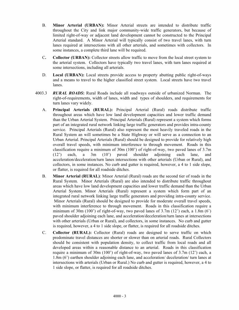
B. Minor Arterial (URBAN): Minor Arterial streets are intended to distribute traffic throughout the City and link major community-wide traffic generators, but because of limited right-of-way or adjacent land development cannot be constructed to the Principal Arterial standard. A Minor Arterial will typically consist of two travel lanes, with turn lanes required at intersections with all other arterials, and sometimes with collectors. In some instances, a complete third lane will be required.
C. Collector (URBAN): Collector streets allow traffic to move from the local street system to the arterial system. Collectors have typically two travel lanes, with turn lanes required at some intersections, including all arterials.
D. Local (URBAN): Local streets provide access to property abutting public right-of-ways and a means to travel to the higher classified street system. Local streets have two travel lanes.
4003.3 RURAL ROADS: Rural Roads include all roadways outside of urbanized Norman. The right-of-requirements, width of lanes, width and types of shoulders, and requirements for turn lanes vary widely.
A. Principal Arterials (RURAL): Principal Arterial (Rural) roads distribute traffic throughout areas which have low land development capacities and lower traffic demand than the Urban Arterial System. Principal Arterials (Rural) represent a system which forms part of an integrated rural network linking large traffic generators and provides intra-county service. Principal Arterials (Rural) also represent the most heavily traveled roads in the Rural System an will sometimes be a State Highway or will serve as a connection to an Urban Arterial. Principal Arterials (Rural) should be designed to provide for relatively high overall travel speeds, with minimum interference to through movement. Roads in this classification require a minimum of 30m (100’) of right-of-way, two paved lanes of 3.7m (12’) each, a 3m (10’) paved shoulder adjoining each lane, and acceleration/deceleration/turn lanes intersections with other arterials (Urban or Rural), and collectors, in some instances. No curb and gutter is required, however, a 4 to 1 side slope, or flatter, is required for all roadside ditches.
B. Minor Arterial (RURAL): Minor Arterial (Rural) roads are the second tier of roads in the Rural System. Minor Arterials (Rural) are also intended to distribute traffic throughout areas which have low land development capacities and lower traffic demand than the Urban Arterial System. Minor Arterials (Rural) represent a system which form part of an integrated rural network linking large traffic generators and providing intra-county service. Minor Arterials (Rural) should be designed to provide for moderate overall travel speeds, with minimum interference to through movement. Roads in this classification require a minimum of 30m (100’) of right-of-way, two paved lanes of 3.7m (12’) each, a 1.8m (6’) paved shoulder adjoining each lane, and acceleration/deceleration/turn lanes at intersections with other arterials (Urban or Rural), and collectors, in some instances. No curb and gutter is required, however, a 4 to 1 side slope, or flatter, is required for all roadside ditches.
C. Collector (RURAL): Collector (Rural) roads are designed to serve traffic on which predominate travel distances are shorter or slower than on arterial roads. Rural Collectors should be consistent with population density, to collect traffic from local roads and all developed areas within a reasonable distance to an arterial. Roads in this classification require a minimum of 30m (100’) of right-of-way, two paved lanes of 3.7m (12’) each, a 1.8m (6’) earthen shoulder adjoining each lane, and acceleration/ deceleration/ turn lanes at intersections with arterials (Urban or Rural.) No curb and gutter is required, however, a 4 to 1 side slope, or flatter, is required for all roadside ditches.
4000 - 3

D. Local (RURAL): Local (Rural) roads are designed primarily to provide access to adjacent land and provide service to travel over relatively short distances as compared to collectors or other higher systems. Roads in this classification require a minimum of 24m (80’) of right-of-way, two paved lanes of 3.4m (11’) each with a 1.2m (4’) earthen shoulder adjoining each lane. No curb and gutter is required, however, a 4 to 1 side slope, or flatter, is required for all roadside ditches.
4004 STREETS
4004.1 MINIMUM STREET WIDTH: Width of streets shall be according to the classifications as provided for in the City's Street and Highway Map of the currently adopted Land Use Plan. Width shall be measured from curb face to curb face or from edge of design strength pavement.
Widths Street Name ROW Pavement Shoulder
Urban Streets
Principal Arterial 30m(100') 15.8m (52') C & G Minor Arterial Varies Varies C & G Collector 18m (60') 10.4m (34') C & G Local 15m (50') 8m (26') C & G
Rural Roads Principal Arterial 30m (100') 7.3m (24') 3m (10') Paved Minor Arterial 30m (100') 7.3m (24') 1.8 m (6')
Paved Collector 30m (100') 7.3m (24') 1.8m (6') Earthen Local(section line) 24m (80') 6.7m (22') 1.2m (4') Earthen Local(interior) 15m (50') w/7.6m (25’) UE/DE 6.7m (22') 1.2m (4') Earthen
4004.2 All secondary and primary arterial street designs shall be furnished by the City Engineer's office.
4004.3 Where Residential Estate (RE) zoning has been allowed, the typical pavement section shall be a minimum width of 6.7 m (22') with 1.2 m (4') turf shoulders on each side. Additional easements or right-of-way shall be dedicated such that the roadside ditch, including the back slope, can be maintained from within the street right-of-way. Roadside ditches shall be constructed in accordance with the City's Standard Specifications and Construction Drawings.
4004.4 All streets shall be constructed with concrete curbs, except as provided for in Section 4003.3, in accordance with the Standard Specifications and Construction Drawings.
4004.5 The centerline of paving shall be the centerline of right-of-way where dedication has been made according to the major street plan. All other cases shall be determined by the City Engineer.
4004.6 The minimum design grade for streets and gutter shall be 0.6 percent with minimum constructed grade of 0.4 percent or greater. The maximum grade for non-arterial streets shall be limited to 8 percent. Where the topography is hilly, grades will be permitted up to a maximum of 12 percent providing they do not exceed 150 m (500') in length from PT to PC, except in areas near intersections, where the 8% maximum will apply.
4004.7 All vertical and horizontal curves shall be designed according to the current AASHTO Specifications using the criteria of safe stopping sight distance.
4000 - 4

4004.8 Vertical sag curves shall be the minimum length available for the two intersecting grades as defined by the AASHTO publication titled, A Policy on Geometric Design of Highways and Streets (Green Book), current revision. For residential streets, no sag vertical curve shall be used if the algebraic difference between the two intersecting grades does not exceed 2%. For collector streets, sag vertical curve length shall be determined by the "comfort equation" contained in the referenced AASHTO publication.
4004.9 Design speed shall be 40 km/h (25 mph) on all residential and collector streets and 72 km/h (45 mph) on arterial streets except as modified by the City Traffic Engineer.
4004.10 For horizontal curves the minimum centerline radius on street alignment shall be 60 m (200').
4004.11 The minimum radius on returns at residential intersections and at intersections of a residential and arterial street shall be 9 m (30'). At intersections of arterial streets, the minimum radius on returns shall be 12 m (40'). The minimum radius on the returns for industrial districts shall be 12 m (40'). Larger radius may be required for industrial districts if specified by the City Traffic Engineer.
4004.12 A proposed and existing profile shall be shown beyond the end of all dead end streets for a minimum of 60 m (200') to determine a satisfactory grade for future development.
4004.13 Cross slope may be 2% or 3% (1/4" or 3/8" per foot).
4004.14 Where proposed development is adjacent to an existing arterial street not constructed to the approved width and pavement dimensions of the currently adopted Land Use Plan and “Standard Specifications and Construction Drawings”, the City shall be provided with a report detailing the existing condition of the roadway. Information to be provided, at a minimum, will include the type of pavement, thickness of pavement, estimated age of the pavement, type of subgrade, and CBR for the subgrade material. The proposed design shall be approved by the Public Works Director.
4005 INTERSECTION DESIGN
4005.1 GENERAL
A. Streets shall intersect one another at right angles (90º) unless topography and other design factors require a waiver by the City Traffic Engineer.
B. Proposed residential areas shall not use four (4) leg intersections within the development.
C. Grades at collector/arterial intersections and 15 m (50') back of radius point shall not exceed 3%.
D. For residential and collector streets the portion of the street from the gutter line of the street being intersected to the P.C. (point of curvature) of the curb return (typically 30 feet) shall have a maximum longitudinal grade of 2%. This will allow the crosswalk to meet the requirements of the Americans with Disabilities Act, which has a maximum sidewalk cross slope of 2%. (See Drawing ST-12)
4000 - 5

4005.2 SIGHT DISTANCE TRIANGLE (VISION TRIANGLE)
A. The intersection sight distance provisions contained in ‘A Policy on Geometric Design of Highways and Streets’ published by the American Association of State Highway and Transportation Officials (the AASHTO Green Book referenced in Section 4008) are adopted as the presumptive standard applicable to all intersections within the City provided, however, that the Director of Public Works or his designee may, where consistent with public safety, specify greater or lesser intersection sight distances. Unless otherwise required by the Director of Public Works or his designee, all intersections shall be designed, constructed and maintained in accordance with such sight distance provision. Additionally, no landscaping, fence, utility equipment, wall or other structure in excess of thirty six inches in height above the roadway shall be constructed or maintained in the area identified as the sight triangle, nor shall any parking be allowed within the area of the sight triangle.
B. Streets shall not be designed with intersections on the inside of horizontal curves or at any location in general where sight distance will be inadequate for drivers to tell if they can safely enter the traffic flow or cross the street. The minimum distance from an intersection to a curve shall be the applicable minimum sight distance listed below. The Director of Public Works or his designee may make exceptions for especially difficult design circumstances only if visibility easements to provide adequate sight distance are established. In lieu of visibility easements, additional street right-of-way may be dedicated. Minimum intersection design sight distance standards, as specified in the AASHTO “Green Book” shall be as follows:
Design Speed (MPH) Minimum Sight Distance (Feet) *
25 280 30 355 35 415 40 470 45 530 50 590 55 645 60 705
* Distance measured from an entering driver’s eye position to the position of the closest approaching vehicle’s far front corner
The entering driver’s eye position shall be assumed 3 feet to the right of the entering street’s centerline, 3.5 feet above the pavement surface, and 9 feet to the nearest pedestrian crosswalk line (marked or unmarked) on the street being entered.
The position of the closest approaching vehicle’s far front corner shall be assumed 3 feet from the edge of the nearest approaching vehicle lane and 4.24 feet above the pavement surface for each direction of travel.
4000 - 6

C. Where stop control is not used, the corner sight distance for residential streets shall be a minimum of 70 m (200') [100 m (300') recommended].
D. To maintain the minimum sight distance, restrictions on height of embankment, locations of buildings, and screening fences may be necessary. Landscaping in the sight distance triangle shall be low-growing, and shall not be higher than 0.9 m (3') above the level of the intersecting street pavements. Tree overhang shall be trimmed to a line at least 2.4 m (8') above the level of the intersections.
4005.3 RIGHT-OF-WAY
A. Intersections containing primary arterials/secondary arterials as classified by the Major Streets and Highways Map of the “Norman 2020 Land and Transportation Plan” shall provide a width of one hundred twenty (120) feet of public right-of-way for a distance of two hundred (200) feet from the intersecting right-of-way. Said right-of-way shall then have a one hundred fifty-foot transition from the one hundred twenty-foot width to a one hundred foot standard width.
B. Variations to this right-of-way requirement shall be granted in accordance with the procedure for plat variations contained in the Subdivision Regulations of the City of Norman, Oklahoma.
4006 TRAFFIC IMPACT OF DEVELOPMENTS
4006.1 GENERAL
When a development will have a significant impact on the traffic pattern (100 vph increase, or more) of the adjacent streets, driveways, and intersections, the developer shall provide a traffic impact analysis. The developer shall provide additional traffic lanes and right-of-way width to the streets or other improvements to mitigate the impact of the development. The City Traffic Engineer shall determine the exact type and quantity of construction required. Each development will be evaluated based on the traffic into and out of the development, the traffic load on the arterial, and current and planned configuration of the arterial, as shown in the City's Major Street and Highway Plan and the trip generation rates for the proposed development, including future phases.
4006.2 GEOMETRIC DESIGN CRITERIA
Intersection design (storage, tapers, grades, etc.) shall be based on National Cooperative Highway Research Report 279, INTERSECTION CHANNELIZATION DESIGN GUIDE, Transportation Research Board, National Research Council, latest edition.
4006.3 OUTSIDE LANE
A. An outside lane shall be required when:
1. The development is within 300 m (1,000') of an arterial type intersection.
2. The arterial will be at or above 130 percent of level C capacity with the addition of the traffic from the development.
4000 - 7

4006.4 DECELERATION LANE
A. A deceleration lane is a right turn into a development that has a lane width of not less than 4 m (13') feet wide for a distance of not less than 30 m (100') plus corner radius, measured from the center line of the road on which the right turn is to be executed, and a thirty (30) to one (1) taper back to the existing arterial street width.
B. A deceleration lane is required when:
1. The number of vehicles making a right turn from the arterial is 100 vehicles per hour (vph) or more during the peak period.
2. Topography makes the deceleration lane necessary for safety.
3. Unsignalized capacity analysis indicates the need for it.
4007 TYPICAL SECTIONS 4007.1 Typical sections shall be drawn at the same horizontal and vertical scale.
4007.2 Typical sections shall show dimensions, type of materials, layer details, reserve topsoil, temporary and permanent erosion control, compacted thickness, etc..
4007.3 All typical sections or notes that are necessary to clearly reflect the design shall be included.
4007.4 The developer shall provide soil tests for all areas to be paved. Soil tests will be submitted to the City Engineer for review. If soil tests indicate that the soil has a plasticity index of 14 or greater, a minimum of 150 mm (6") of subgrade shall be modified with a minimum of 5 percent hydrated lime by weight or Class C fly ash or other suitable material reviewed by the City Engineer. If the soil tests indicate that the soil is granular and unstable, the subgrade shall be stabilized with cement or fly ash. Minimum CBR of compacted and/or stabilized subgrade shall be 8.0. If desired, subgrade may be built of an accepted borrow material.
4007.5 Pavement thickness shall be designed according to Section 4015; however, industrial and commercial pavement sections shall have a minimum thickness of 200 mm (8”) asphaltic concrete or (7”) Portland cement concrete. Residential pavement sections shall have a minimum thickness of (6") asphaltic concrete or (6") Portland cement concrete.
4007.6 Portland cement concrete streets shall have an integrally placed curb of the same mix design as for street paving. Curbs shall be in accordance with the Standard Specifications and Construction Drawings.
4007.7 Joints in Portland cement concrete shall be located in accordance with Standard Specifications Sections 2304.4 and 2304.5. A joint layout plan shall be reviewed by the City Engineer.
4007.8 Joints in Portland cement concrete paving, curbs and gutters shall be constructed in accordance with ODOT Standards unless otherwise accepted by the City Engineer.
4007.9 Asphaltic concrete streets shall have a Portland cement concrete curb and gutter. The curb shall be in accordance with the Standard Specifications and Construction Drawings.
4007.10 All curb sections shall be vertical curb. Mountable type curbs will not be allowed unless accepted for specific sites by the City Engineer.
4007.11 Asphaltic Concrete shall be Superpave Types S 3,4 & 5 per the latest edition of the Oklahoma Department of Transportation Standard Specifications for Highway Construction.
4000 - 8

4007.12 All concrete shall be in accordance with Sections 509 and 701, of the latest edition of the ODOT “Standard Specifications for Highway Construction.”
CLASS DESCRIPTION CONCRETE USES AA 4000 PSI, 7 SACK
or 658 LB CEMENT Bridge Floors, Approach Slabs, Reinforced Concrete Piles, Drilled Shaft Foundations, Parapet Walls, Concrete Rail, and Handrails.
A 3000 PSI, 6 SACK or 564 LB CEMENT
Pavements, Sidewalk and Driveway Approaches, Roadway Culverts, and all Reinforced Concrete not requiring either Class AA or S Concrete.
S 3000 PSI, 6 SACK or 564 LB CEMENT
Pier Caps, Columns, Abutments, Retaining Walls, Bridge Box Culverts, and all Reinforced Concrete not requiring Class AA Concrete.
C 2400 PSI, 4.2 SACK or 395 LB CEMENT
Soil Erosion Control Structures.
4007.13 Where Residential Estate (RE) zoning has been allowed the typical roadway section shall be designed and constructed in accordance with the Standard Specifications and Construction Drawings.
4008 CROSS SECTIONS 4008.1 Cross sections may be required by the City Engineer as a part of the construction plans
when necessary to reflect more clearly the intent of the design.
4008.2 All cross sections for street rights of way shall be drawn to scale showing existing ground and proposed construction from building line to building line.
4008.3 Typical cross sections shall be shown for each street if the slope to the property line exceeds 2%.
4008.4 Each section shall be stationed clearly.
4008.5 The beginning and ending points of a project shall be stationed and cross sections for both the stations shall be drawn.
4008.6 Typical interval between cross sections shall be 20 m (50'). Additional cross sections shall be included as needed.
4008.7 Sufficient roadside information shall be furnished to show that water is not ponded behind curbs or in ditches.
4008.8 Scale for cross sections shall not be less than:
Channels 1:100 (1" = 10') Horizontal 1:50 (1" = 5') Vertical Streets 1:50 (1" - 5') Horizontal 1:50 (1" = 5') Vertical
4009 STRUCTURES AND SPECIFIC DETAILS 4009.1 All special structures will be detailed.
4009.2 Special structures shall be drawn to scale unless noted otherwise.
4009.3 Sufficient details, dimensions and related notes shall be provided for all structures.
4009.4 All structures subject to vehicular traffic shall be designed for H-20 loading.
4009.5 All bridge design shall meet the requirements in the latest edition of Standard Specifications for Highway Bridges prepared by AASHTO.
4000 - 9

4010 SIDEWALKS 4010.1 All sidewalk layouts and designs shall be reviewed by the City Engineer. Sidewalk widths
shall be 1.2 m (4 ft). wide on local and collector streets and 1.5 m (5 ft.) wide on arterial streets. When a sidewalk is constructed adjacent to the street curb and gutter, it shall be constructed 0.3 m (l foot) wider. Sidewalks parallel to arterial roads with designated bike paths shall be 2.4 meters (8 ft.) wide.
4010.2 Sidewalks shall be required on both sides of local, collector, and arterial streets.
4010.3 All sidewalks shall consist of concrete (ODOT Class A, 6 sack, 3000 psi, water/cement ratio of 0.48, 1” to 3” Slump). Sidewalks shall include pedestrian bridges across creeks and streams where applicable.
4010.4 The finished thickness of Portland cement concrete sidewalks shall not be less than 100 mm (4") and the width shall be not less than 1.2 m (4'). Sidewalks across driveways shall be 150 mm (6") thick.
4010.5 Immediately after finishing operations, curing shall be accomplished by either wetted earth, cotton mats, wet burlap bags, membrane curing compounds, or other methods accepted by the City Engineer.
4010.6 In general, sidewalks shall be constructed within the dedicated right-of-way at a distance no less than one foot from the abutting property lines, and except at intersections or as reviewed by the City, shall be no less than 0.9 m (3') from the outside curb line of the street pavements. However, at the home builders option he may construct the sidewalk where it crosses the driveway approach adjacent to the street to allow more space for parking between the garage and the sidewalk.
4010.7 Sidewalks must provide access for the safe and convenient movement across curbs of physically disabled persons, including those persons in wheelchairs. Wheelchair ramps shall be constructed in accordance with the City's Standard Specifications and Construction Drawings and the Americans with Disabilities Act (ADA).
4010.8 To accommodate wheelchair passing space, sidewalks less than 5’ wide shall have at least 5’ by 5’ passing spaces located at intervals not to exceed 200'. Driveways may be utilized as appropriate, provided that the cross-slope of the driveway on each side of the sidewalk does not exceed 2%.
4010.9 Transverse crack control joints shall be placed at intervals not to exceed 1.5 m (5'). Joints shall be tooled or sawed to a depth of 25 mm (1").
4010.10 Expansion joints shall be placed at curbs, driveways, or abutting structures.
4010.11 Where sidewalks intersect drainage flumes, the sidewalks shall span the flume if the flume is the principal drainage between the lots and the sidewalks may slope into the flume if the flume is constructed to act as an overflow.
4000 - 10

4010.12 Detectable warnings shall be required on the end of curb ramps and shall consist of raised truncated domes with a diameter of nominal (0.9 in) 23 mm, a height of nominal (0.2 in) 5 mm and a center-to-center spacing of nominal (2.35 in) 60 mm, shall be the full width of the ramp walking surface, (24 in) 600 mm length from the end of ramp and shall contrast visually with adjoining surfaces, either light-on-dark, or dark-on-light. The material used to provide contrast should contrast by at least 70%. Contrast in percent is determined by:
Contrast = [(B1 - B2)/B1] x 100 where B1 = light reflectance value (LRV) of the lighter area and B2 = light reflectance value (LRV) of the darker area. Note that in any application both white and black are never absolute; thus, B1 never equals 100 and B2 is always greater than zero. The City Engineer shall approve the detectable warning material and method of installation.
4010.13 Changes in horizontal alignment of a sidewalk (See Standard Drawing No. 14b). 4011 DRIVEWAY APPROACH STANDARDS
4011.1 GENERAL A. A driveway approach sketch shall be submitted with the driveway permit application for
review by the Engineering Division. B. A variance from the driveway approach standards described in this section and contained in
the City's Standard Specifications and Construction Drawings may be granted upon review by the Director of Public Works and City Engineer. During the absence of either the Director of Public Works or City Engineer, the Traffic Engineer shall replace the absent party.
C. A driveway approach installation and/or maintenance not meeting the requirements of the driveway approach standards may be corrected by the City if deemed necessary by the Public Works Department, at the expense of the property owner and after notice to the property owner to correct the problem.
D. Specifications for all materials used in constructing a driveway approach shall be reviewed by the City Engineer.
E. All subgrade shall be compacted to 95% standard proctor density before any paving material shall be placed. However, no tests will be required.
F. At the intersection of public roads, driveways shall be located so that the dimension measured along the edge of the travelway "C" is greater than the frontage boundary line (F.B.L.), and the tangent projection of the nearest edge of the driveway is greater than 30 m (100') (for commercial and industrial driveways) or 9 m (30') (for residential driveways). (Refer to the Standard Specifications and Construction Drawings).
G. All private roads, driveways, or streets serving residential, commercial, or industrial developments within the City, the use of which is not restricted, but is open to the public, either by connection with an existing street or because the design thereof does, in fact, constitute a thoroughfare accessible to the public, shall be constructed to specifications required for local streets.
4000 - 11

H. Approach types:
Description Type
Driveway approach on street located in agricultural or residential estate zoning I Driveway approach on street or areas other than agricultural or residential estate zoning (urban areas) II
I. All concrete driveway approaches shall use 24.1 MPa (3000 psi) concrete and be a minimum of 6” thick. All commercial driveways shall be concrete and may be thicker than 6” if required by the City Engineer.
J. The expansion joint at the right-of-way line may be redwood or cedar, if asphaltic expansion joint material is used at the building (garage if the building is a residential home).
K. Residential lots with access either to a collector or local street shall not have driveway access to an arterial street. A residential lot at the corner of a local and collector street shall not have driveway access to the collector without the approval of the Public Works Director.
L. Every driveway approach shall be connected to a parking pad/drive of the same width or larger than the approach and a minimum of 20' deep beyond the Right of Way (ROW) Line (limited by: Zoning Ordinance 22:421.1 ss 3f - concerning paving coverage of yard, drainage impact on surrounding properties, utility easement accessibility, collector access or Historic District Impact).
M. In the Historic District, the minimum driveway width shall be 8 feet and the maximum 10 feet. Also, two strips of concrete, 18” wide shall be allowed.
4011.2 APPROACH GRADES
A. Minimum approach width is 3 m (10').
B. Grades suggested for driveway conditions are as follows:
Approach
Maximum Grade Change
Condition Grade
Desirable
Maximum
High Volume Driveway
6%
0%
3%
Low Volume Driveway on Arterial or Collector Streets
6%
3%
6% Low Volume Driveway on Local Street
10%
6%
12%
C. The maximum difference between the downward cross slope of the street (usually 2.0% or less) and the upward slope of the driveway approach shall not exceed 12.0%.
4000 - 12

4011.3 SPECIAL CONDITIONS
A. Type I Driveway Approaches (streets located in agricultural or residential estate zoning)
1. Neither the intersection point of the driveway approach with the edge of pavement or the end of drainage culvert pipe shall extend past the projected side property line, unless written permission is given by the affected property owner.
2. The driveway approach shall be constructed using materials listed in the following chart:
Minimum Material Standards
Required Driveway Approach
Existing treet S
Material
Thickness
Concrete
Concrete
6"
Asphalt
Type S5 Asphalt
4"* Chip Seal
Type S5 Asphalt
4"
Crushed Rock
1.5" Crushed Rock
5" Dirt
1.5" Crushed Rock
5"
* 6" if commercial
3. Drainage pipe may be constructed of corrugated metal, and reinforced concrete. The minimum pipe diameter shall be 15" or equivalent.
4. A drainage culvert pipe may not be required if the proposed driveway is located in an area with little to no contributing drainage area and a shallow ditch, 12" depth or less. The Engineering Division shall determine if a drainage culvert pipe is required.
4000 - 13

B. Type II Driveway Approaches (streets located in areas other than agricultural or residential estates)
1. All driveway approaches shall consist of concrete (ODOT Class A, 6 sack, 3000 psi, water/cement ratio of 0.48, 1” to 3” Slump), 150 mm (6") minimum thickness. For driveway thickness of 200 mm (8") or greater, dowels are required at contraction joints and at joint connection with the street per Section 2304.4.A.4
2. At right-of-way line, the drive shall be .28 ft. above the top of the existing curb.
3. Connections to the existing curb will meet and match the old curb. 4. Between driveways, construct a minimum 3 m (10') width pedestrian safety island at
and parallel to the property line.
5. Where the existing pavement is asphalt or concrete with a separate concrete curb and gutter, remove both curb and gutter, then construct driveway and gutter as one unit.
6. Immediately after finishing operations, curing shall be accomplished by either wetted earth, cotton mats, wet burlap bags, membrane curing compounds, or other methods accepted by the City Engineer.
7. Sawed contraction joints shall be made as soon as the concrete has set firmly enough to support the concrete saw without tracking. The joints shall be filled with rubberized asphalt or other material accepted by the City Engineer.
8. All exposed edges shall be tooled to no less than 6 mm (1/4") radius (curb backs and slabs).
9. Neither the intersection point of the driveway approach with the edge of pavement or the end of drainage culvert pipe shall extend past the projected side property line, unless written permission is given by the affected property owner.
C. Temporary End-of-Pavement Sections
1. A gravel turn-around area will be provided at the temporary end of any street length in excess of 150 feet. The gravel turn-around will consist of either a gravel circle or a T shaped turn-around. The radius of the turn-around will be a minimum of 38-feet, and the gravel thickness will be a minimum of 6-inches. The T turn-around will be as per City Standard ST-35.
2. Where a temporary end of street is less than 150 feet in length, one of the following shall be installed at the end of the pavement section: either a 12-inch wide concrete header curb, or an additional 5-feet of asphaltic pavement. In both cases, this end of pavement material shall be removed prior to extending the pavement section.
4012 SIGNAGE 4012.1 Street and traffic control sign plans shall be prepared by the City Traffic Engineer. 4012.2 The developer shall be responsible for street name and other traffic control signage in all
subdivisions, both public and private. For public subdivisions, the City will furnish and install these signs for the developer on the basis of the City's current price schedule. For private subdivisions, the developer may, at his option, pay the City for the installation of the signs or hire a private contractor to do the work. Either way, the signs shall meet the requirements outlined in the Manual on Uniform Traffic Control Devices, latest edition. Payment for public subdivision signs shall be made to the City before the final plat is filed. In the case of private subdivision, either payment to the City or installation of the signs by a private contractor will be required prior to the filing of the final plat.
4012.3 A Work Zone Traffic Control Plan shall be provided to the City Traffic Engineer for review before any work is done on existing streets.
4000 - 14
4013 STRIPING
4013.1 Plans for striping of streets requiring striping shall be reviewed by the City Traffic Engineer. Contractor shall be approved by City Traffic Engineer.
4013.2 Striping materials shall be in accordance with Section 2304.7 of the City's Standard Specifications and Construction Drawings.
4013.3 Striping shall be in accordance with the following schedule:
Vehicles per Day Striping Material
Over 4,000 Thermoplastic, full thickness
2,000 - 4,000 Thermoplastic, half thickness
Under 2,000 Paint
4014 EASEMENT AND RIGHT-OF-WAY 4014.1 Easements and rights-of-way shall be clearly dimensioned on the plans. For curved
roadways, additional right-of-way may be required to maintain adequate sight distance.
4014.2 All overland restricted drainage easements will be shown detailed on the Plans and Final Plat, as well as described in the conditions and restrictions of the plat.
4014.3 An unimproved drainageway left in a natural state shall be dedicated to the public, either by title or easement, and platted with a minimum width equal to the floodplain width required to pass the 100-year flood event. Dedicated drainageway shall be provided with adequate vehicular ingress and egress for maintenance purposes. If said drainageway width is less than 45 m (150') the minimum width required will be the floodplain plus an additional width of 4.5 m (15') on each side of the floodplain. Said dedication may have an ownership reverter provision.
4014.4 The City may accept dedication of the entire floodplain area for an unimproved channel.
4014.5 Adequate restrictive easements for dedicated right of way must be provided for access and maintenance of the drainage facilities.
4015 PAVING DESIGN
4015.1 AASHTO METHOD Street pavements shall be designed on the basis of Guide For The Design of Pavement Structure, American Association of State Transportation Officials (AASHTO), 1993 edition and current amendments. Computations shall be performed on an up-to-date version of a computer software program Pavement Analysis Software, developed by the American Concrete Pavement Association.
4015.2 DESIGN PARAMETERS A. Traffic Volumes
Street Class ADT No. Lots
Residential 300-700 50-120 Residential Collector 2,000-6,000 350-1025 Arterial traffic volumes shall be based on the current City Transportation Plan.
B. Truck Traffic Volumes
Truck traffic for various axle loads, taking into account truck traffic during construction, shall be estimated from Table 4015.1.
4000 - 15

TABLE 4015.1 TRUCK TRAFFIC
FOR RESIDENTIAL AND RESIDENTIAL COLLECTOR STREETS
(1)
AXLE LOAD (K)
(2)
CONSTRUCTION (Per Lot)
(3)
OCCASIONAL (Per Lot Per
Year)
(4)
REGULAR (Per Year)
Tandem:
18/23/23
36
0.503
104 Single:
12/22
42
0.123
348 10/18
38
2.68
1456
Note: Traffic volumes are total vehicles per year. Values for each truck category, for input to the paving design software are calculated as follows:
Trucks per year = [Col. (2) * No. Lots / Design Period] + [Col. 3 * No. Lots] + Col. (4)
C. Design Period: The street pavements shall be designed for a period of 20 years.
D. Reliability Factor:
Street Class Reliability Factor
Residential 65 Collector 85 Arterial 90
E. Drainage Coefficient: Except as accepted by the City Engineer for specific conditions, supported by geotechnical testing, coefficient of drainage shall be 1.05.
F. Geotechnical Data: The pavement design software utilizes the resilient modulus (MR) as the basis of its computations. However, the laboratory testing to determine MR is quite expensive; therefore, other parameters, i.e. California Bearing Ratio (CBR) or subgrade modulus (k), may be used. There are approximate relationships between CBR or k and MR. Table 4015.2 contains approximate range of values which may be used, if a specific relationship for the specific subgrade material is not known. The City Engineer must accept geotechnical values used in the pavement design.
4000 - 16

TABLE 4015.2 RELATIONSHIPS BETWEEN SOIL TYPES
AND BEARING VALUES
Type of Soil
Subgrade Strength
k Value Range (pci)
MR (psi)
CBR
Silts & clays of high compressibility1 natural
ensity d
Very Low
50-100
1000-1900
< 3
Fine grain soils in which silt & clay size particles predominate (low ompressibility)c 2
Low
100-150
1900-2900
3-5.5
Poorly graded sands & soils that are predominately sandy with moderate amounts
f silts and clays o
Medium
150-220
2900-4300
5.5-12
Gravely soils, well-graded sands, and sand gravel mixtures relatively free of plastic ines f
High
220-250+
4300-4850
>12
Source: Simplified Guide for the Design of Concrete Pavements, American Concrete Pavement Association, 1993.
G. Material Coefficients: Acceptable coefficients for conversion of depth of various types of materials are as follows:
Flexible Pavement
Type of Layer
Layer Coefficient
Per Inch of DepthSurface Course – “S 4 & 5” HMAC 0.44
Base – “S3” HMAC 0.40
Subbase – Modified Subgrade, CKD (CBR 24) 0.10
“ , Fly Ash (CBR 40) 0.12
“ , Cement (CBR 100) 0.14
“ , Lime (CBR 24) 0.10
Type A Aggregate (CBR 100) 0.14
Prepared Roadbed – Compacted Subgrade 0.04
Note: For other layer coefficients, see “AASHTO Guide for Design of Pavement Structures.” Proposed layer coefficients shall be approved by the City Engineer.
4000 - 17

4016 LIGHTING 4016.1 GENERAL
A. Street lights shall be installed by the franchised vendor providing the electrical service and shall be shown on the preliminary plat.
B. Four basic objectives shall be considered in providing street lighting: aesthetics, traffic safety, security, and intersection identification. The objectives to be considered are directly related to the function of the street to be lighted.
1. For major thoroughfares, the primary objectives are aesthetics and traffic safety.
2. For minor streets and local collectors, the primary objectives are security and intersection identification.
C. Light poles shall be located a minimum of 1.5 m (5') back of curb or future curb, including left and right turn lanes.
4016.2 SCHEDULING: Street lighting shall be chronologically integrated with development. Street lighting shall not be installed until all required offsite improvements such as water mains, sanitary sewer mains, paving, and drainage structures are completed and accepted by the City, to avoid conflicts with other Contractors and workmen. However, it shall be installed prior to extensive development to avoid interference with private landscaping. A good rule to follow is to order street lighting at the same time that street name signs are ordered. Close coordination with the developer is required for lights to be installed in time to avoid interference with private landscaping.
4016.3 LOCATION AND DESIGN
A. Generally, street lighting shall be installed in all zones except A-1, A-2, and R-E, as development occurs. However, street lighting may be considered in A-1, A-2, and R-E zones if they are bordered or traversed by a major thoroughfare, and if that major thoroughfare has been improved to current City standards.
B. The following guidelines shall be followed in providing lighting on minor streets and local collectors:
1. One 4,000 lumen street light at each street or alley intersection.
2. One 4,000 lumen street light at each end of each cul-de-sac or other permanently dead ended street.
3. One 4,000 lumen street light at the approximate midpoint of curvilinear streets that prohibit visual contact between intersections.
4. One 4,000 lumen street light midway between intersections that are spaced 210 m (700') or more apart.
C. The spacing and sizing of thoroughfare lighting shall be in accordance with the criteria of Roadway Lighting Handbook, U.S. Department of Transportation, Federal Highway Administration, current revision.
4000 - 18

4016.4 APPROVALS
A. Requests for street lighting shall be submitted to the office of the City Traffic Engineer. Lighting for minor streets and local collectors shall be reviewed by the City Traffic Engineer and forwarded to the franchised vendor on forms provided by the vendor. Lighting for minor streets and collectors which are not as specified herein shall require the review of the City Traffic Engineer and the Director of Public Works.
B. Proposals for thoroughfare lighting shall be submitted in letter form to the franchised vendor by the City Traffic Engineer, with final allowance to proceed with installation by the Director of Public Works.
C. The City Traffic Engineer will document in writing reasons for denying a request for lighting.
4017 CUT BACK PARKING ON PUBLIC RIGHT-OF-WAY
A. New cut back parking areas will be allowed only on roadways carrying less than an average of 1,000 vehicles per day. Where allowed, sufficient maneuvering space for safe backing must be provided. The minimum width of the parking area, measured perpendicularly from the edge of the travel lane, shall be as follows:
Parking Angle Minimum Width
0 Degrees (Parallel) 21 Feet
30 Degrees 27 Feet
45 Degrees 33 Feet
60 Degrees 39 Feet
90 Degrees (Perpendicular) 43 Feet
Cut back parking areas shall be paved in accordance with the applicable adopted City paving standard. Curb shall be constructed to prevent parked vehicles from encroaching into unpaved areas or sidewalks.
4000 - 19

4018 ARTERIAL ACCESS A. Direct access to arterial roadways must be avoided wherever possible.
B. Whenever possible, joint access with an adjoining property must be sought.
If city officials are satisfied that sufficient attempts to secure joint access have been made and that joint access is still not possible, and access can not be provided via another street, driveway access to the arterial may be granted if the minimum corner clearance is met. However, this access will be limited to right turns in and out.
C. Adequate sight distances will be required at every driveway. Any movement for which inadequate sight distance is available will not be permitted.
D. Each development area will be permitted to have one access driveway, either on the parcel or as part of joint access. Where side streets abut the parcel, the access will be provided from the side street. Additional driveways may be needed and provided under the following conditions:
1. If the daily traffic volume using the driveway exceeds 2,000 vehicles per day.
2. If traffic using one driveway exceeds the capacity of a single stop controlled intersection during one peak street traffic hour or the peak site traffic hour.
3. If a competent traffic analysis shows that traffic conditions warrant additional driveways.
E. In all cases, minimum spacing and clearances shall be provided. F. Driveways along arterial roadways must satisfy the following minimum spacing
requirements:
Posted Speed
Small Generator Medium Generator Large Generator
0 to 100 peak hour trips
101 to 200 peak hour trips
201 and more peak hour trips
< 40 MPH 220 Feet 330 Feet 550 Feet > 40 MPH 330 Feet 440 Feet 660 Feet
Distances are from centerline to centerline of driveway
G. The corner clearance for driveways next to public road intersections shall meet the following criteria:
Speeds < 40 MPH Speeds > 40 MPH
Signal Control Stop Control Signal Control Stop Control 175 Feet * 100 Feet 350 Feet* 200 Feet
* The Director of Public Works or his designee may, where consistent with public safety, specify greater distances in order to keep driveways away form queuing areas and thus assure adequate traffic flow through the intersection.
END OF SECTION 4000
4000 - 20

City of Norman ENGINEERING DESIGN CRITERIA SECTION 5000 STORMWATER
5001 GENERAL REQUIREMENTS
5001.1 If a Stormwater Master Drainage Plan is adopted for the area under consideration, proposed stormwater drainage systems shall comply with the provisions of the plan.
5001.2 A Maintenance Bond or Irrevocable Letter of Credit shall be posted in an amount equal to 25 percent of the determined amount of construction costs for a three-year period after completion and acceptance of all improvements.
5001.3 It shall be the responsibility of all owners of property, whether undeveloped, developed, or undergoing development to:
A. Mow and provide minor maintenance of drainage channels and their slopes for that portion of the channel lying within their property line.
B. Keep clear all drainage channels within the boundaries of their properties in accordance with the requirements of this article.
C. Control all storm water runoff and drainage, erosion and sedimentation from points and surfaces on the property.
D. Prevent any and all drainage interferences, obstructions, blockages, or other adverse effects upon drainage, into, through, or out of the property.
E. Not take any action which will alter or otherwise change designed and installed storm water management control systems and not take any action on existing property that shall adversely affect stormwater runoff in any manner contrary to the provisions of this Section, whether temporary, permanent, or a combination thereof.
F. The City may require improvements, provision of drainage easements, and for provision of improvements, agreements, and/or easements beyond the boundaries of the subdivision, development , or property improvement to facilitate flow of stormwater from or through the property, to avoid damage from changed runoff conditions, to provide continuous improvement of the overall storm drainage system, and to accommodate all drainage conditions or requirements. Where stormwater runoff flows require the logical extension of any street or its associated drainage in order to prevent flooding, ponding, or uncontrolled runoff, the extension shall be provided by the developer.
G. 1. During all construction activity and all other non-construction activity developers, property owners and contractors shall be required to keep streets, gutters, inlets, drainage pipes, swales, ditches, drainage channel, and all drainage devices and structures clean and free from debris, sedimentation, soil, and any materials. Any failure to meet this requirement shall, upon notice and failure to immediately correct the notified condition, constitute sufficient grounds for initiation of enforcement action, including, but not limited to, stopping all work until correction is completed.
5000 - 1
2. Developers, property owners, or their legal agents, upon receipt of notice by the City of Norman that repair or maintenance is required within a channel lying within their property, shall be responsible for effecting such repair or maintenance within the time specified, or the City shall have repair and maintenance performed at the expense of the property owner.

5001.4 It shall be the responsibility of the City of Norman to:
A. Repair and maintain drainage channels and their slopes when located within or upon rights-of-way dedicated to the City of Norman.
B. Develop and implement standards and specifications required to clearly and accurately interpret the physical requirements of this section.
C. Design and implement a Drainage Master Plan for urban drainage, storm water management, and flood control.
D. Make such necessary improvements of primary and secondary drainage channels that cannot or will not be improved through private development.
E. Improve and maintain floodway and flood fringe areas that are dedicated public areas, rights-of-way, park lands, or public-owned buildings or developments.
F. Improve and maintain all public-owned drainage channels or systems outside the flood fringe area.
5002 EASEMENTS
5002.1 All overland restricted drainage easements will be shown detailed on the Plans and Final Plat, as well as described in the conditions and restrictions of the plat.
5002.2 An unimproved drainageway left in a natural state shall be dedicated to the public, either by title or easement, and platted with a minimum width equal to the floodplain width required to pass the regulatory flood. Dedicated drainageway shall be provided with adequate vehicular ingress and egress for maintenance purposes. If said drainageway width is less than 45 m (150'), the minimum width required will be the floodplain plus an additional width of 4.6 m (15') on each side of the floodplain. A permanently visible monument shall be set on each P.I. and on each property line at its intersection with the easement or right-of-way line to identify the limits of the drainage. Said monuments are to conform to adopted City Standards.
5002.3 The City may accept dedication of the entire floodplain area for an unimproved channel.
5002.4 Adequate restrictive easements for dedicated right-of-way must be provided for access and maintenance.
5002.5 The minimum width for all storm sewer easements shall be 4.6 m (15') or the outside diameter of pipe plus 3 m (10'), whichever is greater, and the pipe shall be laid in the center of easement.
5003 DRAINAGE SYSTEM REQUIREMENTS
5003.1 All stormwater runoff shall be reviewed and accepted by the City Engineer with regard to analysis, design and construction of drainage facilities. The appropriate public authority shall have the right to maintain or to cause to be maintained the drainage system for its intended purposes. Floodplain variances must be accepted by the Floodplain Permit Committee.
5003.2 Drainage facilities, both public and private, shall consist of all elements necessary to convey stormwater runoff from its contact with the earth to its disposition in the Little River or the Canadian River.
5000 - 2

5003.3 The drainage system, both public and private, may consist of storm sewers (which are closed conduits); improved channels constructed in conformity with adopted City Standards; unimproved drainageways left in their natural condition; the areas covered by restricted drainage easements for the purpose of providing overland flow; and all appurtenances to the above including inlet, manholes, junction boxes, headwalls, dissipators, culverts, etc. All portions of the drainage system that exist on dedicated rights-of-way or restricted drainage easements shall be owned and maintained by the City, unless provided otherwise by agreement or covenant.
5003.4 The stormwater drainage system shall be designed to receive and pass the runoff from a 100-year frequency rainstorm within dedicated easements under full urbanization. Full urbanization is defined as the total development in an area that is anticipated. The entire flow shall be confined within the said stormwater drainage system.
5003.5 The stormwater collection system shall be designed for either of the following conditions:
A. Convey:
1. A minimum of the runoff from a 10-year frequency rainstorm in a pipe network with overland flow capacities so that the combination of any two will pass the runoff from a 100-year frequency rainstorm under fully urbanized conditions; or
2. The entire runoff from a 100-year frequency rainstorm may be contained in the pipe network. Should the entire runoff from a 100-year frequency rainstorm be conveyed in a pipe network, a bypass system shall be designed considering the pipe network to be 50% blocked. If it can be demonstrated that, in unique situations, property damage or flooding will not occur, a smaller by-pass system may be approved by the Public Works Director or City Engineer.
3. The overland flow and by-pass system mentioned in Sections 5003.5(A)1 and 5003.5(A)2 above shall be a concrete flume when located between houses or in cases deemed appropriate by the City Engineer where there is a potential for wooden fences to be built across said drainage way.
B. Where sump collection systems are used, an overflow route shall be established in the event of complete blockage of the sump.
C. Runoff from areas greater that one half (1/2) acre outside the roadway shall be collected before it reaches the roadway. Parking lots shall have internal drainage systems so as to reduce concentrated flows into streets. This item does not apply to single family residential lots on local streets.
D. Inlets shall be located at intersections to prevent the flow from crossing the intersection. Inlets at intersections shall be located so they do not encroach upon the curb return. No drainage structure shall be permitted at a wheelchair ramp.
E. Drainage areas, runoff from 10-year and 100-year frequency rainstorms, time of concentration, and inlet design for each inlet shall be summarized and tabulated on the plans. This summary table shall also be a part of the drainage calculations.
F. No flumes will be allowed to discharge onto arterials. Flumes discharging onto collectors and local streets are strongly discouraged and shall be allowed by the City Engineer only if there is absolutely no other reasonable solution.
5000 - 3

5003.6 The overland flow portion of the collector system shall be confined to dedicated rights-of-way, or restricted drainage easements to assure that stormwater can pass through the development without inundating the lowest level of any building, dwelling, or structure. Restricted drainage easements shall be shown on the plat. The stormwater runoff from no more than 3 lots shall be allowed onto another lot or between 2 lots. If more lots or area needs to be drained, then an underground storm sewer shall be required.
5004 RAINFALL
5004.1 INTRODUCTION. Presented in this section is the design rainfall data to be used for runoff hydrograph calculations and the Rational Method. All hydrological analyses for the City of Norman shall utilize the rainfall data presented herein for calculation of storm runoff.
5004.2 TOTAL RAINFALL. US Weather Bureau Technical Paper No. 40, Rainfall Frequency Atlas of the United States was used for cumulative rainfall data of storm durations greater than one hour. The National Oceanic and Atmospheric Administration (NOAA) Technical Memorandum NWS HYDRO-35 was used for cumulative rainfall data of storm durations from 5 to 60 minutes. Rainfall data to be used for projects in the City of Norman is contained in Table 5004.1
TABLE 5004.1
TOTAL RAINFALL DEPTHS
DURATION
TOTAL RAINFALL - INCHES
Frequency (Return Period)
1-year
2-year
5-year
10-year
25-year
50-year
100-year
500-year
5-minute
0.40
0.48
0.56
0.62
0.72
0.79
0.86
1.01
10-minute
0.71
0.84
0.99
1.11
1.27
1.41
1.54
1.83
15-minute
0.84
1.01
1.20
1.34
1.54
1.70
1.86
2.23
30-minute
1.14
1.40
1.73
1.96
2.29
2.55
2.81
3.39
1-hour
1.44
1.81
2.28
2.60
3.07
3.44
3.80
4.58
2-hour
1.70
2.13
2.80
3.30
3.85
4.44
5.00
6.12
3-hour
1.87
2.28
3.13
3.63
4.25
4.83
5.43
6.60
6-hour
2.19
2.71
3.64
4.30
5.08
5.71
6.40
7.80
12-hour
2.63
3.23
4.31
5.10
6.00
6.71
7.55
9.20
24 hour
3.00
3.75
5.15
5.88
7.00
7.78
8.75
10.68
Source: U.S. Weather Bureau Technical Paper No. 40 and HYDRO-35
5000 - 4

5005 RUNOFF
5005.1 APPROVED METHODS
A. Table 5005.1 contains methods of runoff which analysis may be used for the design of components of the storm drainage system as applicable.
5005.2 RATIONAL METHOD
A. Formula: The Rational Method is based on the formula: Q = CIA
"Q" is defined as the maximum rate of runoff in cubic feet per second. "C" is a runoff coefficient of the area. "I" is the average intensity of rainfall in inches per hour for a duration equal to the time of concentration. The time of concentration is the time required for water to flow from the most remote point of the basin to the point being investigated and to reach a steady state condition. "A" is the contributing watershed area in acres.
TABLE 5005.1
Applicable for
Minimum. Drainage Area, AC
Maximum
Drainage Area, AC
Peak Q
Volume Calc.
Rational Method
Yes
No
0
200
SCS Method
Yes
Yes
2
2000
USGS Regression Equations
Yes
No
200
None
Modified Rational
No
Yes
0
200
B. Time of Concentration: 1. One of the basic assumptions underlying the Rational Method is that runoff is a function
of the average rainfall rate during the time required for water to flow from the most remote part of the drainage area to the point under consideration.
2. The time of concentration consists of overland flow time, To plus the time of travel, Tf, in the storm sewer, paved gutter, roadside drainage ditch, or drainage channel. For non-urban areas, the time of concentration consists of an overland flow time, To, plus the time of travel in a combined form, such as a small swale, channel, or drainage. The latter portion, Tf, of the time of concentration can be estimated from the hydraulic properties of the storm sewer, gutter, swale, ditch, or drainage. Overland flow time, on the other hand, will vary with surface slope, surface cover and distance of surface flow. The infiltration rate of the soil, the presence of depression storage areas and the amount of antecedent rainfall will also affect the inlet time, since the rainfall must first overcome these losses before a steady state runoff condition will be achieved. Thus, the time of concentration can be calculated using the following equation:
5000 - 5

Tc = To + Tf
In which Tc = time of concentration (minutes)
To = initial, or overland flow time (minutes)
Tf = travel time in the ditch, channel, gutter, storm sewer, etc. (minutes)
Minimum time of concentration, Tc, shall be 5 minutes. 3. The overland flow time, To, in non-urbanized watersheds may be calculated as follows:
To = 1.8 (1.1-C)(Lo 0.5)/(So 0.333)
Where C = runoff coefficient
Lo = length of overland flow, (feet, 500-feet maximum)
So = average basin slope (percent)
In lieu of the foregoing, formulas may be used as contained in the ODOT Roadway Design Manual, Section 15.3.2.1.
4. The equation for overland flow time, To, is generally adequate for distances up to 500 feet. For longer basin lengths, the runoff will combine and the sheet flow assumption is no longer valid. The time of concentration would then be overland flow in combination with the travel time, Tf, which is calculated using the hydraulic properties of the swale, ditch, or channel. The time of concentration is then the sum of the initial flow time, To, and the travel time, Tf.
C. Runoff Coefficient: The runoff coefficient, C, represents the integrated effects of infiltration, evaporation, retention, flow routing, and interception, all of which affect the time distribution and peak rate of runoff. Determination of the runoff coefficient requires judgment and understanding on the part of the engineer. Table 5005.2 presents the recommended range of C values for different surface characteristics as well as for different aggregate land uses. Coefficient values selected from the range available shall be consistent with the urbanized percent imperviousness (i.e. minimum percent imperviousness requires minimum runoff coefficient value). Also, for flat slopes and permeable soils, use the lower values. For steep slopes and impermeable soils use the higher values.
D. Intensity:. The intensity, I, is the average rainfall rate in inches per hour for the period of maximum rainfall of a given frequency having a duration equal to the time of concentration. For a given time of concentration, Tc, and a given design storm frequency, the rainfall intensity, I, can be obtained using the following equation:
I = d / (Tc + e)f
Where I = Rainfall Intensity, inches per hour
Tc = Time of Concentration, minutes
d, e, f = Parameters defined in Table 5005.3.
5000 - 6

TABLE 5005.2
RUNOFF COEFFICIENTS AND PERCENT IMPERVIOUSNESS
Land Use or Surface Characteristic Percent Imperviousness
Runoff Coefficients
BUSINESS:
Commercial Areas Neighborhood Areas
70 to 95 60 to 80
0.70 to 0.95* *
RESIDENTIAL:
Single Family Multi-unit (detached) Multi-unit (attached) 1/2 acre lot or larger Apartments
35 to 60 45 to 55 65 to 75 30 to 45 65 to 75
0.47 to 0.64* * * * *
INDUSTRIAL
Light uses Heavy uses
70 to 80 80 to 90
* *
PARKS, CEMETERIES
4 to 8
*
PLAYGROUNDS
40 to 60
*
RAILROAD YARDS
35 to 45
*
STREETS
Paved Gravel
90 to 100 50 to 70
0.95 0.65
DRIVES AND WALKS
90 to 100
0.95
ROOFS 85 to 95 0.95 LAWNS
Sandy soils Clayey soils
5 to 10 10 to 30
0.10 to 0.20 0.13 to 0.35
RUNOFF COEFFICIENTS - SCS HYDROLOGIC SOIL GROUPS
Land Use or Surface Characteristic A B C D LAWNS AND PASTURES
Flat 0-2% Average 2-6% Steep greater than 6%
0.08 0.13 0.18
0.15 0.20 0.25
0.22 0.27 0.32
0.30 0.35 0.40
WOODLAND Flat Average Steep
0.06 0.11 0.17
0.13 0.18 0.23
0.20 0.25 0.29
0.26 0.31 0.36
MEADOW Flat Average Steep
0.05 0.10 0.15
0.12 0.17 0.22
0.19 0.24 0.29
0.25 0.30 0.35
CULTIVATED Flat 0.20 0.27 0.34 0.40
* Runoff coefficient to be calculated using actual impervious area and soil type.
5000 - 7

TABLE 5005.3 RAINFALL INTENSITY PARAMETERS
Design Storm
Parameter
d
e
f
2 Year
56.43
11.5
0.81
5 Year
72
15
0.80
10 Year
82
15
0.80
25 Year
95
15
0.80
50 Year
108
15
0.80
100 Year
120
15
0.80
Source: Drainage Design Manual, ODOT, February, 1988
5005.2 UNIT HYDROGRAPH METHODS
A. Introduction: A hydrograph method must be used to determine peak runoff rates from watersheds larger than 200 acres, which is the upper limit of the Rational Method and for all detention pond analyses. A hydrograph method is required for all drainage areas larger than two acres. Table 5005.1 indicates methods applicable to various size watersheds. This section contains brief explanations of the various hydrograph methods; however, the design engineer is assumed to be familiar with the basic assumptions and limitations regarding the applicability of the method used.
B. Design Storm Precipitation:
1. The design storm for the Norman area shall have a duration a minimum of twice the time of concentration for peak flow calculations. For design of detention storage basins, a 24 hour storm shall be used,.
2. A precipitation hyetograph shall be used as the input for all runoff calculations. The specified precipitation is assumed to be uniformly distributed over the watershed. The hyetograph represents average precipitation depths over a computation interval.
3. The unit duration incremented shall be in multiples of one, two or five minutes (e.g., 1-, 2-, 5-, 10-, or 15-minutes) with the maximum unit duration to be 15 minutes under most circumstances. An acceptable unit storm duration should not exceed one-fifth of the time to peak of the watershed, tp. As an example, if the watershed has a tp of 35 minutes, then an appropriate unit storm duration would be five minutes.
C. SCS Unit Hydrograph Method: The Soil Conservation Service (SCS) method is presented in detail in Section 4 of the U.S. Department of Agriculture Soil Conservation Service Engineering Handbook and Model Drainage Manual, American Association of State Highway and Transportation Officials, 1991. The SCS computer program TR20 or the U.S. Army Corps of Engineers computer program HEC-1 are acceptable ways of utilizing the SCS methodology. The SCS publication TR55 may be used for areas up to 2,000 acres.
5000 - 8
D. USGS Regression Equations: The United States Geological Survey (USGS) regression equations for ungaged streams can be found in the USGS publication, "Techniques for Estimating Flood Discharges for Oklahoma Streams", Water Resources Investigation 77-54, U.S. Geological Survey, Water Resources Division, June 1977.
5006 STREET DRAINAGE
5006.1 CRITERIA FOR STREET DRAINAGE
A. Depth in Streets: Use of streets for conveyance of stormwater runoff shall be within the following limitations:
1. For the 50-year frequency rainstorm, two 8 foot wide driving lanes of an arterial street shall remain open. Depth of flow for collector and local streets shall not exceed 50 mm (6”).
2. The 100-year flow shall be contained within the right-of-way.
3. At sump locations, the water depth shall not exceed 0.3 m (12") above the top of the grate for the 100-year frequency rainstorm.
4. Where sump collection systems are used, an overflow route shall be established in the event of complete blockage of the sump in accordance with Section 5003.3.
B. Location of Storm Sewers: Storm sewer shall not be placed within the wheelpath of any driving lane of the pavement. The preferred location of the storm sewer is according to the following order of priority listed.
• Behind the Curb
• Down the Center of the Traffic Lane
• On Centerline
The traffic lane is defined as the normal width provided for each lane and delineated by pavement stripes.
5006.2 DRAINAGE IMPACT ON STREETS
A. Sheet Flow: To minimize the effects of hydro-planing and splashing of sheet flow, the streets of Norman are designed with a 2% (1/4" per foot) or 3% (3/8" per foot) cross slope. In addition, for arterial streets, the amount of flow permitted in the street is limited to the outside lane before a storm sewer inlet is required (Refer to Section 5006.1.A).
B. Cross Flow: The depth of cross flow permitted in non-arterial streets, where it cannot be avoided, is limited to the top of curb. Cross flow in arterial streets is not permitted and is strongly discouraged for collectors and residential streets. The cross flow limitations for freeways are determined by the Oklahoma Department of Transportation.
C. Valley Gutters: Concrete valley gutters are required in asphalt streets when the longitudinal grade is 1% or less. The width of the valley gutter will be determined by the depth required. The maximum slope of the lateral grade shall be 5% when the valley gutter is located at or near a stop sign. When the valley gutter is located in mid block with a speed limit of 25 mph the cross slope shall be a maximum of 3%. No mid block valley gutters shall be allowed if the speed limit is greater than 25 mph. If a bird bath exists on an asphalt valley greater than 1%, then a concrete valley gutter shall be constructed.
5000 - 9

5006.3 HYDRAULIC EVALUATION
A. Curb and Gutter Capacity:
1. The allowable storm capacity of each street section with curb and gutter shall be calculated using the modified Manning's formula:
Q = 0.56(Z/N)S1/2YT8/3
Where Q = discharge in cfs
Z = reciprocal of the street cross slope (Sx, ft/ft)
YT = depth of flow at the gutter (feet)
S = longitudinal grade of street (ft/ft)
N = Manning's roughness coefficient
2. Manning's roughness coefficient, N, shall be used according to the applicable construction condition from Table 5006.1.
3. When the street cross section has different cross slopes, capacity computation shall take into account the various cross slopes.
B. Roadside Ditch Capacity: The capacity of a roadside ditch shall be computed using Manning's equation. The allowable flow over the paved portion of the street is computed according to Section 5006.3.A. This capacity of the roadside ditch and street capacity are combined to determine the entire street section capacity. The paved street portion contributes to the total capacity only when the depth of flow in the roadside ditch is exceeded for the design storm. As in streets with curb and gutter, the maximum allowable depth at the pavement edge shall not exceed the limits set in Section 5006.1.C.
TABLE 5006.1 MANNING'S N-VALUES
FOR STREET GUTTERS
Construction Type N
Concrete gutter troweled finish 0.012
Asphalt Pavement Smooth texture Rough Texture
0.013
.016 0 Concrete gutter with asphalt pavement Smooth Rough
0.013
.015 0 Concrete pavement Float finish Broom finish
0.014
.016 0 Brick
0.016
Note: For gutters on flat grade where sediment may accumulate, increase all above values of N by 0.002.
Source: Drainage Design Manual, ODOT, February, 1988
5000 - 10

5007 STORM SEWER INLETS 5007.1 DESIGN CRITERIA
A. Inlet Types: 1. Three types of inlets are used in the City of Norman: curb opening inlets, combination
grated and curb opening inlets and median inlets. Multiple inlets occur when more than one inlet (of the same type) are used in a continuous series, resulting in greater flow interception capacity.
2. Inlet types shall be in accordance with the City's Standard Drawings.
3. On arterial streets, offset type inlet, ODOT Standard SSCD-1-15, shall be used.
4. Minimum size shall be 2 hoods and 2 grates.
B. Location of Inlets: 1. Inlets shall be located at all low points in the gutter grade, on side streets at intersections
where runoff would flow onto an arterial street or highway and upgrade of bridges to prevent runoff from flowing onto the bridge deck. Inlets are also required when the allowable depth of flow in the gutter is exceeded.
2. Inlets at intersections shall be located in such a manner that no part of the inlet will encroach upon the curb return. Inlets on a continuous grade in the interior of a block should be placed upstream of a nearby driveway, if possible. The flowline and top of curb elevations shall be shown on all inlets.
C. Spacing Between Inlets: The spacing between inlets shall be such that depths of flow and widths of spread requirements are not violated.
D. Interception and Bypass: 1. Attempting to intercept all the flow on a street at every inlet leads to a costly storm sewer
system. It is more cost effective to allow some portion of the runoff to bypass an inlet and intercept the runoff at the next inlet. Another cost effective method is to design as many of the inlets as possible to be sump inlets.
2. The type of inlet to be used and the percent of flow to be intercepted at a particular location is left to the judgment of the designer. The objective is to minimize the cost of the storm sewer system while satisfying all of the design criteria. In general, an interception rate of 70 to 80 percent will result in an economical design.
3. Hydraulic design of inlets shall be in accordance with Section 5007.2.
E. Inlets in Sump Condition: When inlets are placed in a sump, emergency overflow shall be provided as described in Section 5003.6.
5007.2 HYDRAULIC EVALUATION A. Methodology: Safety factors for grates and curb openings shall be in accordance with the
ODOT “Drainage Design Manual,” latest edition which states that design interception capacity for curb inlets will be equal to 80% of the computed theoretical capacity Qi.
The Following factors should be appied to the theoretical capacity Qi of grate inlets:
Grate Inlet Condition Thoretical Capacity Design Capacity
Longitudinal bars Sump Qi 0.50 Qi
Longitudinal bars On continuous grade Qi 0.75 Qi
Longitudinal and transversal bars Sump Qi 0.50 Qi
5000 - 11

Longitudinal and transversal bars On continuous grade Qi 0.60 Qi
B. Grate Inlets: 1. Grated inlets without a curb opening are not permitted within City of Norman streets. 2. The bicycle safe grates (in combination with a curb opening) are the only grates approved
by the City of Norman within the street right-of-way. The Neenah R-3076 Vane Grate, or approved equal, shall be used in the City of Norman.
3. When a grate is used in conjunction with a curb opening directly behind the grate, only the hydraulic capacity of the grate shall be utilized to estimate the flow that is intercepted, since the curb opening portion is reserved to collect debris.
4. Grate interception capacities shall be determined for the specific grate to be used in the project. For example, if the grate inlet is manufactured by Neenah Foundry use Neenah's method of computing the capacity.
C. Curb Opening Inlets: Two types of curb opening inlets are approved by the City of Norman: cast in place concrete inlets, and manufactured metal inlets.
5008 STORM SEWER PIPE SYSTEM
5008.1 INTRODUCTION. A "storm sewer system" refers to a system of inlets, pipes, manholes, junctions, outlets, and other appurtenant structures designed to collect and convey storm runoff to a defined drainageway. A "drainage system" also includes curbs and gutters, roadside ditches, swales, channels, and detention systems for the control of overland runoff. In general, a storm sewer system is required when other parts of the drainage system no longer have the capacity for additional runoff without exceeding the design criteria.
5008.2 DESIGN CRITERIA
A. Design Storm Frequency:
1. The storm sewer system, beginning at the upstream end with inlets, is required when the allowable street capacity (see Section 5006.1.A) or overflow capacity is exceeded for the design storm. The "design storm" has three connotations in the City of Norman: The design storm for the piped storm sewer system is the 10 year storm, the street and piped storm sewer system combined is the 50 year storm and the piped storm sewer system, street, and ROW combined is the 100 year storm. Minor system and the design storm for the major system, the 10-year and 50/100-year storm respectively. Thus, the storm sewer system should be designed for the larger of the following events:
a. The 10-year flow, less the allowable capacity of the gutter or roadside ditch; or
b. The flow equal to the difference between the 50-year and the allowable street capacity, to prevent violation of the criteria in Section 5006.1.A; or
c. The flow equal to the difference between the Q100 and the capacity within the ROW, to prevent violation of the criteria in Section 5006.1.A.2.
2. The intent is to intercept the 10-year flood and convey the flow in a storm sewer. However, it is impractical to intercept all the runoff in the street at the inlet and some "carry-over" flow will occur. The procedure simply puts a limit on the amount of carry-over flow that can occur in the street.
B. Construction Materials: Storm sewers within the City of Norman may be constructed using reinforced concrete or corrugated metal. The materials, pipes, and appurtenances shall meet the requirements of the City's Standard Specifications Section 2300.
5000 - 12

C. Vertical Alignment:
1. The sewer grade shall be such that a minimum cover is maintained to withstand AASHTO HS-20 loading on the pipe. The minimum cover depends upon the pipe size, type and class, and soil bedding condition, but shall not be less than one foot from the top of pipe to the finished grade at any point along the pipe. If the pipe encroaches into the street sub-grade, a variance must be granted of the City Engineer.
2. Manholes will be required whenever there is a change in size, alignment, elevation grade and slope, or where there is a junction of two or more sewers. For sewers equal to or larger than 1500 mm (60") diameter, pre-formed smooth transitions shall be approved by the City Engineer. The maximum spacing between manholes for various pipe sizes shall be in accordance with Table 5008.1.
3. The minimum clearance between storm sewer and water main (for new construction), either above or below shall be 300 mm (12"). Ductile iron pipe (with proper bedding) or concrete encasement of the water line will be required for clearances of 300 mm (12") or less when the clearance between existing water mains cannot be maintained.
4. The minimum clearance between storm sewer and sanitary sewer (for new construction), either above or below, shall be 300 mm (12"). In addition, when an existing sanitary sewer main lies above a storm sewer, or within 450 mm (18") below, the sanitary sewer shall have impervious encasement or be constructed of ductile iron pipe for a minimum of 3 m (10') on each side of the storm sewer crossing.
5. Siphons or inverted siphons are not allowed in the storm sewer system.
Table 5008.1
STORM SEWER ALIGNMENT AND SIZE CRITERIA MANHOLE SPACING:
Pipe Size
Maximum Spacing for Manholes
Minimum
Manhole Size
15" to 24"
90m (300')
1.2m (4')
27" to 42" 120m (400')
1.5m (5')
48"
150m (500')
1.8m (6')
54" to 66"
150m (500')
2.4m (8')
>66"
150m (500')
junction structure
MINIMUM RADIUS FOR RADIUS PIPE: Short radius bends shall not be used on sewers 900 mm (36") or less in diameter for public systems.
MINIMUM PIPE DIAMETER: Type Minimum Equivalent
Pipe Diameter Minimum Cross-Sectional Area
Main Trunk
375 mm (15")
0.114m 2(1.23 SF)
Lateral from inlet
375 mm (15")
0.114m2 (1.23 SF)
Source: Stormwater Criteria Manual, City of Tulsa
5000 - 13

TABLE 5008.2
MANNING'S N-VALUE FOR CLOSED CONDUITS
Pipe Material
Minimum n-Value Concrete
.013
Corrugated Metal
1. Annular a) 2 2/3 x 1/2 in b) 3 x 1 in c) 5 x 1 in
2. Helical a) 2 2/3 x 1/2 in
i) 18 in ii) 60 in iii) 36 in iv) 48 in v) ≥ 60 in
b) 3 x 1 in i) 48 in ii) 60 in iii) 66 in iv) ≥ 78 in
c) 5 x 1 in i) 54 in ii) 60 in iii) 66 in iv) ≥ 78 in
0.024 0.027 0.025
0.013 0.015 0.018 0.020 0.021
0.023 0.024 0.026 0.027
0.022 0.023 0.024 0.025
Sources:
1. Drainage Criteria Manual, City of Austin.
2. Modern Sewer Design, American Iron and Steel Institute, 1990.
5000 - 14
D. Horizontal Alignment
1. Storm sewer alignment between manholes shall be straight except when accepted in writing by the City Engineer. Approved curvilinear storm sewers may be constructed using pipe bends or radius pipes.
2. A minimum horizontal clearance of ten feet is required between sanitary and water utilities and the storm sewer.
3. The permitted locations for storm sewer within a street right-of-way are: (a) behind the curb, (b) down the center of the driving lane, and (c) on centerline. Behind the curb is the preferred location.
E. Pipe Size: The minimum allowable pipe size for storm sewers is presented in Table 5008.1
F. Storm Sewer Capacity and Velocity
1. Storm sewer shall be designed to convey the difference between the capacity of the street and the design storm (10-year) flood peaks without surcharging the storm sewer. The sewer may be surcharged during larger floods and under special conditions when approved by the City Engineer.
2. The capacity and velocity shall be based on the Manning's n-values presented in Table 5008.2. The maximum full flow velocity shall be less than 20 fps. Higher velocities may be accepted by the City Engineer if the design includes adequate provisions for uplift forces, dynamic impact forces and abrasion. The minimum velocity in a pipe based on full flow shall be 2.5 fps to avoid excessive accumulations of sediment.
3. The energy grade line (EGL) for the design flow shall be no more than one foot above the final grade at manholes, inlets, or other junctions. To insure that this objective is achieved, the hydraulic grade line (HGL) and the EGL shall be calculated by accounting for pipe friction losses and pipe form losses. Total hydraulic losses will include friction, expansion, contraction, bend, manhole, and junction losses.
G. Storm Sewer Inlets and Outlets
1. Before discharging the runoff from a parking lot of area larger than 0.5 acres, the runoff must first be collected in a storm sewer inlet and connected to the sewer within the street right-of-way, or roadway ditch or drainage conduit. Accordingly, the flow in the street shall be reduced by the amount intercepted by the inlet.
2. All storm sewer outlets into open channels shall be constructed with a headwall and wingwalls or a flared-end-section. When the outlet velocity exceeds six feet per second, erosion control measures shall be taken. If required to prevent erosion, energy dissipaters shall be provided.
3. All storm sewer inlets that can pass a 6” sphere, including outlet structures for detention facilities, will have protective grates approved by the City Engineer.
5000 - 15

H. Riprap Energy Dissipaters
1. Riprap energy dissipaters shall be sized to control erosion at outlets of storm sewer and/or flumes. These energy dissipaters shall be sized accordingly:
a. For discharges onto flat areas (sheet flow conditions), the following formula can be used for riprap dimensions:
Where La = Length of riprap apron (ft) Wu = Width of apron at discharge (ft) Wd = Width of apron at downstream end (ft) t = Depth of apron (ft) do = Mean diameter of riprap required (ft) Q = Q25 discharge (cfs) La = 4.5 * e(0.34*(LN(Q*V)-1.5))
Wu = 3 * do
Wd = do + La t = 1.5 * do do = 4” if Q * V < 100 6” if Q * V > 100 & <200 8” if Q * V > 200 & <500 12” if Q * V > 500 & <2000 18” if Q * V > 2000 & <7000 24” if Q * V > 7000
2. For discharges into established channels, the following formula can be used for riprap dimensions:
Where La = Length of riprap apron (ft) Wu = Width of apron at discharge (ft) Wd = Width of apron at downstream end (ft) t = Depth of apron (ft) do = Mean diameter of riprap required (ft) Q = Q25 discharge (cfs) La = 5.0 * e(0.375*(LN(Q*V)-0.75))
Wu = 3 * do
Wd = do + 0.4*La t = 1.5 * do do = 4” if Q * V < 100 6” if Q * V > 100 & <200 8” if Q * V > 200 & <500 12” if Q * V > 500 & <2000 18” if Q * V > 2000 & <7000 24” if Q * V > 7000
5000 - 16

5009 OPEN CHANNELS
5009.1 CHANNEL DESIGN
A. Design: Channels shall be designed in accordance with sound engineering principles.
B. Channel Geometry: For trapezoidal channels, the minimum bottom width shall be 1.2 m (4') with side slopes of not steeper than 3.5 to 1 for sodded sections and a minimum bottom width of 3' with side slopes of not steeper than 1:1 for paved or rocklined sections. Where the public may be exposed to hazards and nuisances of open channels, appropriate measures shall be taken to exclude the public from the perilous area.
C. Manning's N - Value: Mannings Equation in the calculations of hydraulic characteristics of channels will be acceptable. The "N" value used for channels shall be based on the individual channel characteristics, according to Table 5009.1. Designers should anticipate growth of trees as a natural maturation process of the channel. Values less than 0.05 shall be justified.
TABLE 5009.1
MANNING'S N-VALUE FOR OPEN CHANNELS
Lining Category Lining Type n Value for Given Depth Ranges
0-0.5 ft 0.5-2.0 ft >2.0 ft Rigid Concrete 0.015 0.013 0.013 Grouted Riprap 0.040 0.030 0.028 Stone Masonry 0.042 0.032 0.030 Soil Element 0.025 0.022 0.020 Asphalt 0.018 0.016 0.016 Unlined Bare Soil 0.020 0.020 0.020 Rock Cut 0.045 0.035 0.025 Temporary Woven Paper Net 0.016 0.015 0.015 Jute Net 0.028 0.022 0.019 Fiberglass Roving 0.028 0.021 0.019 Straw with Net 0.065 0.033 0.025 Curled Wood Mat 0.066 0.035 0.028 Synthetic Mat 0.036 0.025 0.021 Gravel Riprap 1 in D50 0.044 0.033 0.030 2 in D50 0.066 0.041 0.034 Rock Riprap 6 in D50 0.104 0.069 0.035 12 in D50 - 0.078 0.040
5000 - 17

Table 5009.2 Classification of Vegetal Covers as to Degree of Retardance
Retardance Class Cover Condition
Weeping Lovegrass Excellent stand, tall, average 2.5 ft A Yellow Bluestem Excellent stand, tall, average3.0 ft
Ischaemum Kudzu Very dense growth, uncut Bermuda grass Good stand, tall, average 1.0 ft Native grass mixture Good stand, unmowed (little bluestem, bluestem,
blue gamma, and other long and short midwest
grasses) B Weeping lovegrass Good stand, tall average 2.0 ft
Lespedeza sericea Good stand, not woody, tall, average 1.6 ft Alfalfa Good stand, uncut, average 0.91 ft Weeping lovegrass Good stand, unmowed, average 1.1 ft Kudzu Dense Growth, uncut blue gamma, and other long Good stand, uncut, average 1.1 ft Crabgrass Fair stand, uncut, average 0.80 to 4.0 ft Bermuda Grass Good stand, mowed, average 0.5 ft Common lespedeza Good stand, uncut, average 0.91 ft Grass-legume mixture- Good stand, uncut, average 0.5 to 1.5 ft
C summer (orchard grass,
redtop Italian ryegrass, and
common lespedeza) Centipedegrass Very dense cover, average 0.5 ft Kentucky bluegrass Good stand, headed, average 0.5 to 1.0 ft Bermuda grass Good stand, cut to 0.2 ft Common lespedeza Excellent stand, uncut, average 0.4 ft Buffalo grass Good stand, uncut, average 0.3 to 0.5 ft
D Grass-legume mixture- Good stand, uncut, 0.3 to 0.4 ft summer (orchard grass,
redtop Italian ryegrass, and common lespedeza)
Lespedeza sericea After cutting to 0.2 ft height, very good stand stand before cutting
E Bermuda grass Good stand, cut to average 0.1 ft Bermuda grass Burned Stubble
5000 - 18

Table 5009.3 Manning’s n Relationships for Vegetal Degree of Retardance Retardance Class Manning's n Equation
A K R1/6 / [K2 + 19.97 log (R1.4 So0.4)]
K = 1.0 K2 = 15.8 B K R1/6 / [K2 + 19.97 log (R1.4 So
0.4)] K = 1.0 K2 = 23.0 C K R1/6 / [K2 + 19.97 log (R1.4 So
0.4)] K = 1.0 K2 = 30.2 D K R1/6 / [K2 + 19.97 log (R1.4 So
0.4)] K = 1.0 K2 = 34.6 E K R1/6 / [K2 + 19.97 log (R1.4 So
0.4)] K = 1.0 K2 = 37.7
D. Minimum Slope: Channels shall have minimum slopes of 0.1% for concrete-lined channels and 0.75% for grass lined channels. The City Engineer's acceptance is required for channels with a flatter slope.
E. Minimum Velocity: Minimum velocity in a drainageway system, having a roughness co-efficient less than or equal to 0.015, shall be 2.5 fps to avoid sedimentation..
F. Maximum Velocities: Maximum velocities in channels shall be based on allowable shear stress for channel lining (See Section L. below). Velocities in concrete lined or paved sections shall not exceed 15 fps. The dissipation of energy shall be required at the confluence of improved channels with natural channels through the use of dissipaters, stilling basins and etc. which shall be designed in accordance with FHWA HEC #14 Hydraulic Design of Energy Dissipators for Culverts and Channels Drainage Manual.
G. Freeboard: Where practical, the design water surface elevation shall be kept below the level of natural ground. A 0.3 m (1') freeboard above the energy grade line should be added to calculated flow depths to determine minimum channel depths.
H. Trickle Channels: All channels altered or improved from the natural state will require a paved trickle channel unless a variance is granted by the City Engineer.. Sodding, or other methods of erosion control shall be required adjacent to the paved channel.
I. Concrete Flumes: Concrete flumes in lieu of enclosed pipe shall be allowed as overflow protection for storm sewer systems, and to drain areas not exceeding five (5) acres in size. All concrete flumes shall extend to the rear of adjacent lots and shall discharge into a dedicated drainage facility or channel. There will be no special freeboard requirement for concrete flumes.
J. Roadside Ditches. Roadside ditches shall conform with requirements of this section.
K. Base Flood Elevation (BFE) or floodplain boundary changes shall be approved by FEMA.
5000 - 19

L. Maximum Shear Stress: the maximum shear stress for a straight channel occurs on the channel bed and is less than or equal to the shear stress at maximum depth. The maximum shear Stress is computed as follows:
τ = γdS
where:
τ = maximum shear stress (lb/ft2)
γ = unit weight of water (62.4 lb/ft3)
d = maximum depth of flow
S = Average bed slope or energy slope (ft/ft)
Table 5009.4
Permissible Shear Stresses for Lining Materials
Lining Category Lining Type
Permissible Shear Stress
Temporary Woven Paper Net 0.15 lb/cf
Jute Net 0.45 lb/cf
Fiberglass Roving: 0.15 lb/cf
Single 0.6 lb/cf Double 0.85 lb/cf Straw with Net 1.45 lb/cf
Curled Wood Mat 1.55 lb/cf
Synthetic Mat 2.00 lb/cf Vegetative Class A 3.70 lb/cf Class B 2.10 lb/cf Class C 1.00 lb/cf Class D 0.60 lb/cf Class E 0.35 lb/cf Gravel Riprap 1 in 0.33 lb/cf 2 in 0.67 lb/cf Rock Riprap 6 in 2.00 lb/cf 12 in 4.00 lb/cf
5000 - 20

5010 HYDRAULIC STRUCTURES
5010.1 DEFINITIONS
A. Culvert: A culvert is defined as a closed conduit for the passage of water under an embankment, such as a road, railroad, or driveway. The distinction between a culvert and a sewer is the means by which flow enters the conduit. Flow normally enters a culvert by an open channel, generally at a similar elevation and a culvert usually crosses a street.
B. Bridge: A bridge is constructed with abutments and superstructures, which are typically concrete, steel, or other materials. Since the superstructures are generally not an integral structural part of the abutments, and are therefore free to move, the hydraulic criteria for bridges is different than for culverts. Bridges are also usually constructed with earth or rock inverts, whereas culverts are typically the same material throughout the waterway opening.
5010.2 CULVERTS
A. Construction Materials: Culverts shall be constructed of reinforced concrete or corrugated metal in accordance with Table 5010.1. Other materials may be used on a case by case basis on acceptance by engineer.
B. Sizing Method: Culvert design shall follow the methodology presented in Hydraulic Design of Highway Culverts, Hydraulic Design Series HDS No. 5, FHWA, U.S. Department of Transportation and Drainage Manual, Oklahoma Department of Transportation, 1992.
C. Design Frequency: Minimum design frequency for culverts shall be 50-year. Impact for 100-year shall be calculated and shown.
D. Minimum Size:
1. Pipe Culverts - 450 mm (18") equivalent
2. Box Culverts - no less than 0.9 m (3') in height
5000 - 21

TABLE 5010.1
CULVERT MATERIALS PIPE MATERIAL
STANDARD
Reinforced Concrete Pipe
Round
Elliptical
Arch
ASTM C-76 or AASHTO M-170
ASTM C-507 or AASHTO M-207
ASTM C-506 or AASHTO M-206 Pre-Cast Concrete Manholes
ASTM C-478 or AASHTO M-199
Pre-Cast Concrete Box
ASTM C-789/C-850, AASHTO M-259/273 or ODOT
Concrete Cast-in-Place Box
ODOT Standard
Corrugated Aluminum Alloy:
Alloy Pipe and Underdrains
Structural Plate
Aluminized Type II Coated
AASHTO M-196
AASHTO M-219
AASHTO M-274 Corrugated Steel
Metallic coated for sewer/drains
Bituminous Coated pipe/arches
Polymer Pre-coated
Structural Plate
AASHTO M-196
AASHTO M-190
AASHTO M-245
AASHTO M-167
5000 - 22
E. Velocity Limitations:
1. In design of culverts both the minimum and maximum velocities must be considered. A minimum velocity of 3- feet per second at the outlet is required to assure a self-cleaning condition of the culvert.
2. The outlet area shall include a headwall with wingwalls or an end-section in addition to the riprap protection if required. Where outlet velocities exceed six feet per second, erosion control measures shall be taken. Energy dissipators shall be provided as required.
F. Structural Design: Culverts shall be designed to withstand an HS-20 loading in accordance with the design procedures of AASHTO Standard Specifications for Highway Bridges and with the pipe manufacturers recommendations. In addition, the AASHTO maximum heights of cover for corrugated metal structures shall also be followed. The minimum cover over top of the pipe shall be .3 m (12") unless otherwise accepted by the City Engineer.
G. Driveway Crossings: Driveway culverts shall be sized to pass the 10-year ditch flow capacity without overtopping the driveway. The minimum size culvert shall be a 450 mm (18") round pipe , or equivalent, for all streets. Sloped headwalls required per the city's Standard Details..
5010.3 BRIDGES
A. Bridge Sizing Criteria The sizing criteria set forth in Section 5010.2 for culverts shall apply as follows:
1. Freeboard - Freeboard is defined as the vertical clearance of the lowest structural member of the bridge superstructure above the water surface elevation of the design frequency flood. The minimum freeboard shall be 1 foot for the 100-year frequency flood, unless accepted by the City Engineer.
2. Backwater - Backwater is defined as the rise in the flood water surface due to the restrictions created by the construction of the bridge. The maximum backwater shall be 1 foot as required by the City floodplain regulations.
B. Velocity Limitations: The velocity limitations through the bridge opening are controlled by the potential abutment scour and subsequent erosion protection provided. Using riprap for the channel lining and/or protection of the abutments and wingwalls, the maximum channel velocity is limited to 15 fps.
C. Hydraulic Analysis: The hydraulic design of bridge crossings shall be in accordance with Drainage Manual, Oklahoma Department of Transportation, 1992.
D. Inlet and Outlet Configuration: The design of bridges shall include adequate wingwalls of sufficient length to prevent abutment erosion and to provide slope stabilization from the embankment to the channel. Erosion protection on the inlet and outlet transition slopes shall be provided to protect from the erosive forces of eddy current.
E. Bridges shall be designed in accordance with AASHTO/ODOT criteria. Rails shall comply with ODOT Standard Details.
5000 - 23

5011 STORAGE AND INFILTRATION 5011.1 GENERAL
A. Generally, urbanization results in more impervious area and a reduction in floodplain storage, both of which contribute to increased flow rates. The development plan shall incorporate permanent, post-construction means (such as basins, ponds, infiltration trenches, dry wells and porous paving) to provide for storm water storage, promote storm water infiltration, and reduce erosion and sediment transport.
B. Peak release rates from developments shall not exceed the existing runoff that occurred before development for all storm frequencies up to and including the 100-year frequency storm. Releases for 2, 5, 10, 25, 50 and 100-year storms shall not exceed the existing rate. If improvements are made to any natural channel downstream from an area which requires a minimum pipe diameter of 1200 mm (48") to discharge a 10-year frequency storm, current floodplain storage must be maintained.
C. The detention storage shall accommodate the excess runoff from a 100-year frequency storm. The excess runoff is that runoff generated due to urbanization which is greater than the runoff historically generated under existing conditions, for a given frequency storm. Detention facilities shall be designed so that the peak rate of discharge does not exceed that of the pre-development conditions for all storm events up to and including 100-year.
D. Detention facilities shall be designed using the City's hydrologic model and hydraulic model for the watershed to assure that there is no adverse impact from water surface elevation or flow velocity.
E. A fee in lieu of detention may be allowed by the City Engineer if the development is located in the upper portion of the drainage basin, the size of the development is small and the developers’ engineer states in writing that there will be no adverse impact downstream.
5011.2 DESIGN CRITERIA A. For the design of storage facilities, the methods contained in Section 5005.1 are approved. B. Reserved. C. The design storm for detention shall be a 24-hour storm. Rainfall depths shall be in
accordance with Section 5004. D. The time increment used in developing the rainfall distribution and in reading off the
ordinates of the unit hydrograph may be rounded off to the nearest whole time interval or to the nearest time increment.
E. Rainfall patterns shall be consistent with the modelling technique used. F. All calculations for detention facilities shall be submitted for review by the City Engineer.
The submittal shall include hydrographs for both existing and developed conditions, detention facility stage-area-volume relationships, outlet structure details, and a stage versus time analysis through the facility.
G. Floodplain areas and detention facility locations shall be identified at the preliminary plat stage to illustrate how these areas will be managed during and after construction.
H. If a tract of land under development has a floodplain area within its boundary, the information that must be furnished either with the preliminary plat or before the final plat is submitted, shall include: 1. A backwater analysis on the existing drainage system. 2. A backwater analysis on the proposed drainageway system
5000 - 24

I. Detention facilities should be located in areas accepted by the City. Each facility shall
incorporate methods to minimize erosion and other maintenance reducing designs. J. Additional detention storage, in excess of the required storage for a drainage area, can be
provided to satisfy the detention requirements for a tract of land downstream of the detention facility, providing the detention facility is constructed prior to the development of the downstream tract.
K. A minimum number of detention facilities is encouraged for each development. Regional detention facilities are encouraged for phased or cooperative development in a drainage basin.
L. If runoff has a natural tendency to drain in several directions for a given development tract of land where detention is required, then detention storage shall be provided for the biggest drainage area. Additionally, a detention storage may be provided, at the same facility, to satisfy detention requirements for a separate drainage area on the same development, provided that; 1. The whole developmental tract of land is in the same watershed.
2. The smaller drainage area(s) that, has/have been compensated for does/do not, either singly or in combination, adversely impact the health, welfare and safety of the general public downstream.
M. If a tract of land being developed is located in more than one watershed, grading work to divert flows from one watershed to another will not be permitted .
N. The detention area shall be identified as a separate platted area; as appropriate, it may consist of one or more platted lots, a separate block, or it may be identified as a reserve area.
O. Provision for the detention facility shall not appear among the plat's restrictive covenants.
P. In the event the detention facility, as a result of drainage improvements, becomes unnecessary, the facility by action of the City Council may be vacated as provided for in the covenants or applicable law.
Q. An accessway at least 20 feet wide shall be provided to any required detention area. Access may be provided by frontage on a dedicated public street or by an access easement from a dedicated public street to the detention area.
R. If the detention facility is approved by the City to serve areas outside the subdivision in which it is located, such additional areas shall be specifically identified in the provision for detention.
S. Any dam or berm shall be designed in accordance with the dam safety criteria of the Oklahoma Water Resources Board.
T. The maintenance responsibility for on site detention facilities shall remain with the private sector and appropriate covenants shall be obtained to secure such maintenance.
U. All detention facilities utilizing closed conduit systems for the main discharge will be required to have an emergency overflow structure capable of passing the 100-year frequency storm.
5000 - 25

5011.3 PHYSICAL FEATURES
A. Detention dams or dikes shall be constructed as earth filled and non-overflow type dams. Embankment slopes shall not be steeper then 4: 1. Spillways shall be constructed to pass the 500-year flood event with a minimum of one (1) foot of freeboard on the earth dam structure.
B. Side slopes on detention facilities shall not be steeper than 4:1.
C. Access road, with grade of 10% or less, shall be provided to the detention areas for maintenance purposes.
D. Detention facilities shall be provided with a 3 foot wide concrete trickle channel from the inlet to the outlet structure to transmit low flows.
E. Storm sewer outlets in the slope of the detention pond shall be protected by a reinforced concrete slopewall.
F. All earth slopes and earth areas subject to erosion, such as, adjacent to low flow channels, inlet structures, and outlet structures shall be slab sodded with bermuda sod or protected with other erosion control measures. All other earth surfaces, within the area designated for detention facility site, shall have an established growth of bermuda grass. All covered areas shall be fertilized, watered and in an established growing condition prior to completion and acceptance of the detention facility.
G. All inlet and outlet structures shall be properly grated so that any object larger than a 6” sphere cannot enter the storm system.
H. Parking lot detention may be utilized upon approval of City Engineer.
1. Where parking lot detention is proposed: (a) The maximum depth of the 100-year storm event shall not be greater than 254 mm
(10”). (b) The maximum coverage of the parking area by the stored storm water shall not be
greater than 25%. 5011.4 FEE-IN-LIEU OF ON-SITE DETENTION A. Requirement: Detention facilities shall be designed using the City's hydrologic model and
hydraulic model for the watershed, if available. An owner shall satisfy his requirement to provide for detention by contributing a fee in lieu of detention to the construction of a regional detention facility or other storm water improvement, if approved, by the City Engineer. Also, detention will be required if there is adverse impact (increase in flow, velocity, base flood elevation, etc.) from the project as determined by the City Engineer and/or the City's hydrology and hydraulic models.
B. Contribution amount: 1. The contribution amount shall be $0.1038 per square foot of additional impervious
surface.
2. Fee rate shall be adjusted yearly, based on Engineering News Record Construction Cost Index and recognizing changes in land costs in the Norman area on the annual anniversary of the approval of this Engineering Design Criteria document.
3. Money contributed shall be paid at the following time: a. Prior to the issuance of the permit for paving or storm sewers, whichever is later. b. When the above permit is not required, prior to the issuance of an Earth Change
Permit. c. When none of the above permits are required, prior to the issuance of a building
5000 - 26

permit. C. The acquisition of regional and sub-regional detention sites and construction of facilities
thereon will be financed by the City. Monies contributed by owners as above provided shall be used for regional and sub-regional detention sites, facilities and maintenance thereof in the watershed in which the development is located.
D. The boundaries of watersheds and priority of acquisition of regional and subregional detention sites and construction of detention facilities and location thereof shall be established by the City Engineer and approved by City Council. The City will determine if fee-in-lieu of on-site detention is applicable to a specified site.
5012 EROSION AND SEDIMENTATION CONTROL 5012.1 PURPOSE
A. This chapter includes standards and requirements for erosion and sedimentation control for construction.
B. The primary concern of the City is minimizing erosion and sedimentation damage during the period of site construction activities until final landscaping and permanent erosion control measures are effectively in place. During site construction, soil loss and consequent damage to adjacent property, receiving streams and reservoirs can increase 100 - 1,000 times over that of the preconstruction environment. Eroded soil endangers water resources by reducing water quality and causing siltation of aquatic habitat for fish and other desirable species. Eroded soil also necessitates repair and maintenance of the storm sewer system.
5012.2 REGULATIONS A. The control of erosion and sedimentation from construction activities shall be in accordance
with this Section and any other pertinent sections of The City of Norman’s “Engineering Design Criteria” and “Standard Specifications and Construction Drawings.”
B. No person may engage in any earth disturbing activities, including developing, grading, excavating, paving, landfilling, berming or diking without first obtaining an Earth Change Permit from the City of Norman. The permit will remain in effect until construction activities have ceased and permanent erosion control measures, including establishment of vegetative cover, are complete. Bona fide agricultural practices and sites less than one acre are exempt from the permit requirements.
C. Prior to commencing any earth disturbing activity, temporary erosion control measures must be installed. Best Management Practices (BMPs) must be selected which will reduce erosion and off-site transport of sediment to the maximum extent practicable.
D. All streets and storm sewers must be kept free of sediment, discarded building material, litter, chemicals, fuels, or fluids. BMPs must be maintained in good and effective condition at all times. BMPs may not be modified or removed without first obtaining approval from the City.
E. The developer/property owner and contractor designated by the developer are responsible for implementation of, and compliance with, the Erosion and Sedimentation Control Plan, and maintenance of erosion control devices. The developer or the designated contractor must apply for the Earth Change Permit. If no contractor is designated, the contractor having day to day operational control of the site is considered to be designated by the developer.
F. Commercial or residential construction sites less than one acre, but which are part of a common plan of development larger than one acre, such as individual residential lots in a subdivision, are required to maintain erosion and storm water pollution prevention measures (BMPs) implemented during development. The BMPs may be modified or temporarily
5000 - 27

removed with approval of the City. If BMPs are absent or not effective, the property owner or designated contractor will, at a minimum, install BMPs to keep streets, drainage ways, and storm drains free from sediment or other construction material or debris.
G. The ODEQ adopted a General Permit for Storm Water Discharges from construction activities, which includes discharges from construction with areas greater than 1 acre in size. The objective of the General Permit is to improve water quality by reducing pollutants in storm water discharges. Authorization to discharge under the General Permit is obtained by submitting a Notice-of-Intent (NOI) along with supplemental information, which is briefly described in this Section. and ODEQ General Permit for Storm Water Discharges from Construction Activities within the State of Oklahoma.
H. Equivalent Program Compliance: Any site permitted by, and in compliance with the ODEQ General Permit for Storm Water Discharges, may be considered by the City of Norman to be in compliance with this chapter.
I. Earth Change Permit and Storm Water Inspection fees shall be assessed according to the City of Norman Standard Specifications and Construction Drawings, Section 3001.8.
5012.3 EXEMPTIONS A. Exemptions from the erosion control submittal process may be granted by the City for
construction areas less than 1-acre. A summary of these exemptions is presented below.
1. Bona fide agricultural and farming operations. 2. Customary and incidental routine grounds maintenance, landscaping, and home
gardening. 3 Maintenance and repairs of utilities made on public or private property. 4. Sites determined by the City to have no significant impact on storm water quality.
5012.4 SUBMITTALS A. Permit Applications
1. All new development shall have prepared and implemented an erosion and sedimentation control plan. The plan shall be prepared and will be reviewed in accordance with the criteria presented in this section.
2. New development disturbing an area greater than 1 acre must obtain authorization to discharge under the ODEQ General Permit for Storm Water Discharges from Construction Activities. Notices of Intent (NOI) must be submitted to:
Storm Water Notice of Intent Oklahoma Department of Environmental Quality Water Quality Division P.O. Box 1677 Oklahoma City, OK 73102-1677
A copy of the NOI must also be submitted to the City with the erosion and sedimentation control plan.
Then City strongly recommends that when a developer files an “NOI” for a development, it will remain in force for the duration of the development, including the development of smaller areas (for example: individual residential lots) that are a part of the larger common plan of the development.
5000 - 28

3. For additional information, contact Storm Water Permitting Water Quality Division Oklahoma Department of Environmental Quality 707 N. Robinson, P.O. Box 1677 Oklahoma City, Oklahoma 73101 (405) 702-8100
4. Erosion Control Plans are in integral part of the Earth Change Permit. Erosion Control Plans are also related to drainage analysis and report requirements.
5. Erosion and Sedimentation Control Plan approval is required prior to issuance of an Earth Change permit. Since the drainage plan has considerable impact on site grading, erosion control planning and drainage planning should be a concurrent process. However, for some developments, site grading to an interim condition may be desired. To account for cases where site grading will precede final drainage planning, the erosion control plan may be submitted with a Preliminary Drainage Report. Subsequently, the plan will need to be modified to reflect grading changes necessitated by final drainage design.
B. Erosion and Sedimentation Control Plan 1. Purpose: The purpose of the Erosion and Sedimentation Control Plan is to identify and
define conceptual solutions to the problems which may occur on site and off site as a result of the development. In addition, those problems anticipated on site and off site during development must be addressed in the report. All reports shall be typed and bound together. The drawings, figures, plates, tables, and site plan shall be bound with the report or included in a folder/pocket at the back of the report.
2. Plan Contents: The narrative report shall contain the applicable information listed: a. Name, address, and telephone number of the applicant, landowner, developer, and
engineer and a copy of the NOI, if required. b. Project description - Briefly describe the nature and purpose of the land disturbing
activity, the amount of grading involved, and project location including section, range, and township. Include a schedule listing the sequence of major events, such as the start of clearing/grading, installation of erosion controls, construction of sediment/storm water basins and final soil stabilization.
c. Existing site conditions - A description of the existing topography, vegetation, and drainage.
d. Immediate Adjacent areas - A description of neighboring areas such as streams, lakes, residential areas, roads, etc., which might be affected by the land disturbance.
e. Soils - A brief description of the soils on the site giving such information as soil names, mapping unit, erosion tendencies, permeability, hydrologic soil group, depth, texture, and soil structure. (This information may be obtained from the S.C.S soil survey for Cleveland County.)
f. Erosion and sediment control measures - A description of the methods which will be used to control erosion and sedimentation on the site.
g. Permanent stabilization - A brief description, including specifications, of how the site will be stabilized after construction is completed. This information is optional for the initial report but may be required for the report addendum.
5000 - 29

h. Stormwater management considerations - Explain how stormwater will be handled. Determine detention requirements. This information is optional for the initial report but may be required for the report addendum.
i. Maintenance - A schedule of regular inspections and repair of erosion and control structures should be set forth. This information is optional for the initial report but may be required for the report addendum.
3. Drawing Contents a. General Location Map: A map shall be provided in sufficient detail to indicate the
location of the project site. The map should be at a scale of 1" = 1000' to 1" = 2000' and should indicate the project site in relation to existing topographic, and transportation, features and land boundaries. The map shall show the drainage area of land tributary to the site. The drawing shall be a multiple of 8-1/2" x 11".
b. Sediment and Erosion Control: Map(s) of the proposed development at a scale of 1" = 20' to 1" = 200' on 22" x 34" drawing sheets shall be included. The plan shall show the following: (1) A boundary line survey of the site on which the work is to be performed. (2) Existing topography at a maximum of two (2) foot contour intervals. The
contours shall extend a minimum of 100-feet beyond the property line (if available).
(3) Proposed topography at a maximum of two (2) foot contour intervals. (4) Location of any existing structure or natural feature on the site. (5) Location of any structure or natural feature on the land adjacent to the site and
within a minimum of 100 feet of the site boundary line. The map shall show the location of the storm sewer, channel, or creek receiving storm runoff from the site.
(6) Location of any proposed additional structures or development on the site, if known.
(7) Limits of clearing and grading - Areas which are to be cleared and graded. (8) The “Sediment and Erosion Control Plan” shall include plans for both pre and
post construction. c. Detailed Drawings: Detailed drawings and structural practices used that are not
referenced in this Manual and other information or detail as may be reasonably required by the City. The size of drawings shall be a multiple of 8-1/2” x 11”.
5012.5 BEST MANAGEMENT PRACTICES
A. The following best management practices (BMPs) for erosion and sedimentation control may be used singly or in combination. Equivalent BMPs may also be used. All controls shall be selected, installed and maintained in accordance with manufacturer’s specifications and good engineering practices. Maintenance and implementation of the controls will be detailed in the Erosion and Storm Water Pollution Control Plan.
5000 - 30

5012.6 TEMPORARY BEST MANAGEMENT PRACTICES A. Dikes:
1. Types a. Diversion dike. b. Interceptor dike. c. Perimeter dike.
2. The design drainage area for dikes shall not exceed 5 acres. 3. The minimum dimensions shall be:
a. Top Width - 2' b. Height - 1.5' c. Side Slopes - 2:1 or flatter
B. Swales: 1. Types:
a. Interceptor swale. b. Perimeter swale.
2. The design drainage area for swales shall not exceed 5 acres. 3. The minimum dimensions shall be:
a. Bottom width - 1.2 m (4') b. Depth - 0.3 m (1') min, c. Grade - 1% min. d. Slopes - 2:1 or flatter
C. Straw Bale Dike: Straw bales will be allowed only when no other erosion control method would be effective. Use of straw bales must be approved by the City Engineer on a case-by-case basis.
D. Silt Fence: Silt fences can be constructed near the perimeter of a disturbed area to intercept sediment while allowing water to percolate through. Silt fences may not be used where there is a concentration of water in a channel or other drainage. The following criteria' are applicable:
1. Drainage area - 2 acre maximum
2. Height - .75 m (30") minimum
3. Material - burlap, polypropylene fabric or nylon reinforced polyester netting.
4. Support - Steel fence posts at 2.4 m (8') maximum spacing.
E. Entrances: A stabilized entrance to all construction sites, shall be built to reduce or eliminate the tracking or flowing of sediment onto public rights of way.
F. Stone Outlets: A stone outlet structure shall be constructed in areas where the entire drainage area to the structure is not stabilized or where there is a need to dispose runoff at a protected outlet or where concentrated flow for the duration of the period of construction needs to be diffused.
5000 - 31

G. Paved Chute: A grade stabilization structure in the form of a paved chute or flume shall be constructed to prevent erosion, where concentrated flow of surface runoff is to be conveyed down a slope. The maximum allowable drainage area upstream of such a structure shall not exceed 36 acres.
H. Pipe Slope Drain: A grade stabilization structure in the form of a pipe slope drain shall be constructed to prevent erosion, where concentrated flow of surface runoff is to be conveyed down a slope. The maximum allowable. drainage area upstream of such a structure shall not exceed 5 acres.
I. Temporary Sedimentation Basin: Storm water detention facilities may be used temporarily as sediment basins. 1. A temporary outlet structure for the storm water detention facility to work as a sediment
pond shall be constructed. 2. At the end of the construction activity, the developer shall make sure that the outlet
structure shall meet the design requirements of a storm water detention facility. 3. Condition of the detention facility that is used as a sediment pond during construction,
shall meet the following requirements at the time of acceptance. a. It shall be completely cleaned by the developer and be rid of any immediate
maintenance. b. It shall meet all design standards.
J. Sediment Trap: A sediment trap, a small temporary basin usually installed in a drainageway at a storm drain inlet shall conform to the following criteria:
1. Drainage area - 5 acres maximum.
2. Trap size - at least 1800 cubic feet per acre of drainage.
3. Embankment: a. Height - 5' maximum b. Top width - 3' minimum c. Slopes - 2:1 or flatter
5012.7 PERMANENT BEST MANAGEMENT PRACTICES
A. Depending on the project layout, a diversion shall be constructed across a slope less than 15% to: 1. Prevent runoff from higher areas having a potential for causing erosion and thereby
interfere with the establishment of vegetation on lower areas. 2. Reduce the length of slopes to minimize soil loss.
B. Diversions need be constructed only below stabilized or protected areas. C. Outlets from diversions shall be constructed to discharge in such a manner as not to cause
erosion. D. Outlets shall be constructed and stabilized prior to the operation of diversion. E. Storm drain outlet protection shall be provided when converting pipe flow to channel flow.
The reduction in velocity shall be consistent with the roughness coefficient of the receiving waterway. The reduction in velocity may be accomplished by: 1. Providing mortared riprap stabilization;
2. Providing energy dissipaters;
3. Providing permanent vegetation; depending on the site specific needs.
5000 - 32

5012.8 VEGETATIVE BEST MANAGEMENT PRACTICES
A. Vegetative practices can be applied very effectively to control erosion. The practice can be either temporary or permanent depending on the site specific needs. The specifications for establishing vegetation both temporary and permanent are briefly outlined below.
B. Temporary Practices
1. Small grains like oats, rye and wheat, and sudans and sorghums are the most feasible temporary vegetation to control erosion for the Norman area. This practice is effective for areas where soil is left exposed for a period of 6 to 12 months. The time period may be shorter during periods of erosion rainfall.
a. Prior to seeding, needed erosion control practices such as diversions, grade stabilization structures, berms, dikes, etc. shall be installed.
b. Temporary vegetative practice is usually applied prior to the completion of final grading of the site.
c. If the area to be seeded has been recently loosened to the extent that an adequate seedbed exists, no additional treatment is required. However, if the area to be seeded is packed, crusted and hard, the top layer of soil shall be loosened by other suitable means.
d. Fertilizer shall be applied at a rate of 600 pounds per acre or 15 pounds per 1000 square foot using 10-20-10 or equivalent.
e. Soils known to be highly acidic shall be lime treated. f. Seeding requirements shall be as specified in Table 5012.1. g. Seeds shall be drilled uniformly. h. Seeding implements should be used at right angles to the general slope to minimize
erosion. i. After 2 to 3 months of planting the seeded site shall be top dressed with 8 pounds per
1000 square feet or 350 pounds per acre of 33-0-0. j. Areas that are not well covered shall be replanted. k. The seeded area shall be watered when feasible and needed.
Table 5012.1 Planting Rates - Temporary Practic e
Plant
Per
Acre
Per
1000 SF Planting
Date Annual Ryegrass 40 lbs. 0.9 lbs. 9/15 - 11/30 Elbon Rye 2 bu. 3.0 lbs. 8/15 - 11/30 Wheat 2 bu. 3.0 lbs. 8/15 - 11/30 Oats 3 bu. 2.5 lbs. 8/15 - 11/30 Sorghum 60 lbs. 1.4 lbs. 3/1 - 9/15 Sudan Grass 40 lbs. 0.9 lbs. 4/1 - 9/15
5000 - 33

C. Permanent Practices: Bermuda grass, Kentucky 31 Tall Fescue, and Old World Blue Stem are some of the permanent vegetation that could be effectively used to control erosion. 1. Prior to seeding, needed erosion control practices such as dikes, swales, diversions, etc.
shall be installed. 2. The subgrade shall be loosened evenly to a depth of 2 to 3 inches and 10-20-10 fertilizer
(10 pounds per 1000 square feet or 450 pounds per acre) shall be mixed with the loosened surface soil by disking or other suitable means.
3. Soils known to be highly acidic shall be lime treated. 4. Planting rate requirements shall be as specified in Table 5012.2:
Table 5012.2
Planting Rates - Permanent Practice Plant
Per
Acre
Per
1000 SF
Planting
Date Bermuda Grass 22 Lbs. 0.5 Lbs. 4/1 - 8/15 Fescue 44 Lbs. 1.0 Lbs. 9/1 - 11/1 Old World Blue Stem 6.1 Lbs. 0.14 Lbs. 4/1 - 6/30
5. Seeds shall be drilled uniformly. 6. Seeding implements should be used at right angles to the general slope to minimize
erosion. 7. Mulch will be used where needed. 8. The area shall be watered daily or as often as necessary to maintain adequate soil
moisture until the plants grow about 1/2 - 1 inch.
D. Buffer Strips: A vegetated buffer strip will be preserved along both sides of all perennial and intermittent streams and adjacent wetlands. The size and location of the buffer strip will be determined during review of the Erosion and Sedimentation Control Plan, prior to any earth disturbing activity. The naturally occurring vegetation in the buffer strip shall not be disturbed. If any vegetation in the buffer strip is disturbed, it shall be immediately restored as much a possible to it’s natural condition.
5012.9 COMPLIANCE
A. Inspections - The City or it’s authorized representative shall be permitted at all times to gain access to any site for purpose of inspection or observation to determine compliance with this Chapter.
B. Stop Work Order/Revocation of Permit: - In the event that any person holding an Earth Change Permit violates the terms of the permit or this Section, the City may revoke or suspend the permit and require a stoppage of all work on site until all violations are corrected. Any person engaged in activities regulated by this Section without first obtaining the required permit will be required to stop all work on site until a permit is obtained.
C. Any person found in violation of the provisions of this Section will be denied issuance of any other City permits, approvals or inspections until the violation(s) is corrected or written arrangements to correct the violation(s) are submitted to, and accepted by, the City.
D. Fines – Any person or entity found to be in violation of any provision of this section may be punished by fines in accordance with Section 16-102 of the City of Norman Code of Ordinances.
END OF SECTION 5000
5000 - 34

City of Norman ENGINEERING DESIGN CRITERIA SECTION 6000 STORM WATER POLLUTION
6001 PURPOSE
6001.1 The purpose of this ordinance is to provide for the health, safety and welfare of people of Norman by the regulation of non-storm water discharges to the city municipal separate storm sewer system (MS4). This ordinance sets forth uniform requirements to regulate the direct or indirect introduction of pollutants into the MS4 in order for the City of Norman (City) to comply with all applicable state and federal laws including National Pollutant Discharge Elimination System (NPDES) Storm Water Regulations (40CFR Part 122).
6001.2 The objectives of this ordinance are to:
A. Control the direct or indirect introduction of pollutants into the MS4 by storm water
discharges from any source or user;
B. Control the introduction into the MS4 of any spills, dumped or disposed material other than storm water;
C. Prohibit illicit connections and illegal discharges to the MS4;
D. To establish legal authority for inspection, surveillance and monitoring of the MS4 to ensure compliance and identify noncompliance with this ordinance;
6002 Definitions
Best Management Practice (BMP) shall mean the best available practices or devices used singly or in combination to eliminate or reduce pollution entering the MS4. Discharge shall mean to cause or allow any release, spill, drain, dump or pour of any pollutants into the MS4. Illicit Discharge shall mean any discharge to the MS4 not composed entirely of storm water except those allowable discharges listed in Sec 01-03.
Illicit Connection shall mean any drain or conveyance, either surface or subsurface which allows an illegal discharge to enter the MS4.
Municipal Separate Storm Sewer System (MS4) shall mean a conveyance or system of conveyances (including streets, curbs, gutters, storm drains, catch basins, natural and man-made channels and ditches) owned by the City of Norman and designed for collecting and conveying storm water.
6000 - 1

Person shall mean any individual, partnership, co-partnership, firm. Company, corporation, association, joint stock company, trust, estate, governmental entity or any other legal entity or their legal representatives, agents or assigns. Pollutant shall mean any dredged spoil, solid waste, incinerator residue, sewage, garbage, sewage sludge, munitions, chemical wastes, biological materials, radioactive materials, wrecked or discharged equipment, rock, sand, cellar dirt, soil, sediment, building materials, industrial or agricultural waste. Pollution shall mean man-made or man-induced alteration to the physical, chemical, biological or radiological properties of water. Premises shall mean any plot or tract of property, regardless of size or plat, owned or used by any person. Storm Water shall mean any flow occurring during or following any form of natural precipitation and resulting therefrom. User shall mean any source of direct or indirect discharge to the City of Norman Municipal Separate Storm Sewer.
6003 Regulations
6003.1 Allowable Discharges The following discharges are allowed unless they are determined by the Director of Public Works (Director) to cause contamination of storm water, surface water or ground water; cause overload or damage to the MS4; endanger public health and safety; or cause the City to violate its ODEQ issued storm water permit or any applicable state or federal permit:
(1) Potable water discharges, including potable water line flushing;
(2) Uncontaminated groundwater;
(3) Uncontaminated water from crawl space and footing drains;
(4) Flows from riparian habitats, wetlands, springs or streams;
(5) Irrigation water;
(6) Residential car washing (including charity car washes)
(7) Air conditioner condensate;
6000 - 2

(8) Discharges resulting from City operations, including street washing, fire fighting, maintenance and repair work;
(9) Any discharge covered by a current OPDES/NPDES permit so long as the
discharge is not in violation of the permit or Section 6003.1 of this ordinance;
(10) Discharges containing chemicals applied according to manufacturer instructions for legitimate residential or commercial use, including legal pesticides, herbicides and fertilizers;
(11) Runoff from agricultural activities, including residential gardening and
landscaping
(12) Any other type of discharge determined allowable by the Director.
(13) De-chlorinated swimming pool discharges.
6003.2 Prohibited Discharges It is prohibited to discharge, allow to discharge, or cause the discharge of any of the following to the MS4:
(1) Non-storm water discharges except those listed in Sec. 6003.1; (2) Any material other than storm water, which is stored, spilled, or disposed of
in such a manner that causes pollutants to be discharged; such as discarded building materials, soil, silt, sediment, vehicle wash water, litter, yard waste, chemicals or any other pollutant.
(3) Any illicit discharge.
6003.3 Portable Spray Washing Discharges to the MS4 resulting from cleaning of vehicle exteriors, parking lots, driveways and other paved areas with portable spray washers are allowed with the following requirements:
(1) Only bio-degradable cleaners are used;
(2) The operator must use best management practices (BMPs) to prevent or reduce the discharge to the MS4;
(3) All other provisions of Sec. 6003.1 are met.
6000 - 3

6003.4 Construction Activities
All earth disturbing construction activities, including developing, grading, excavating, paving, landfilling, berming and diking, shall be performed in such a manner as to minimize erosion and the discharge of sediment and other pollutants into the MS4. All such activities are also subject to the requirements of the City of Norman Engineering Design Criteria for Street, Storm Drainage, Water Lines and Sanitary Sewers as incorporated by reference in Section 16-101 of the City of Norman Code of Ordinances.
6003.5 NPDES Permitted Activities
Any person, business or entity that performs an activity which requires an NPDES Storm Water Permit shall make available to the City copies of permits, applications and any other records or correspondence pertaining to the aforementioned permit.
6003.6 Records
Any person, business or entity which discharges or causes to be discharged storm water to the MS4 may be required to provide the City with copies of any records or correspondence determined to be necessary to ensure compliance with this ordinance.
6003.7 Best Management Practices (BMP)
If a discharge to the City MS4 is, has, or has the potential to cause pollution to the MS4 or local water bodies, BMP(s) must be employed to prevent or reduce the pollution. Additionally, BMP(s) shall be used to prevent spills or other accidental introduction of pollutants into the MS4.
6003.8 Spill Reporting
Within one (1) hour of discovery, oral notification must be made to the Director of any spill, release or other event which has or will likely result in a discharge of pollutants into the MS4. Notification shall include the location, time, type and volume of the event as well as corrective actions taken. Written notification to the Director shall be made within five (5) days of the event.
6000 - 4

6004 Compliance
6004.1 Illicit Discharge Sampling and Inspections
A. Sampling When the Director or authorized representative has reason to believe that a discharge is an illicit discharge, the Director may obtain a suitable sample for analysis. If the discharge is shown to be illicit, full recovery of the cost of sampling and analysis may be made from the responsible party.
B. Inspections The Director or authorized representative shall be permitted to gain access to any premises or property necessary for the purpose of inspection, sampling, observing or monitoring the MS4 to determine compliance with this ordinance.
6004.2 Administrative Enforcement
A. Notice of Violation
Any violation of the provisions of the ordinance may result in the responsible party being issued a Notice of Violation (NOV). The NOV will include a description of the violation and include a reasonable time for the violation to be corrected. Failure to comply with the NOV may result in further enforcement action against the responsible party.
B. Cease and Desist For any violation of the provisions of this ordinance the Director may issue an order requiring the responsible party to cease and desist all violations, to immediately come into compliance with the ordinance and to take any necessary remedial action to reduce or eliminate pollution entering the MS4 from the violation.
C. Administrative Fines Notwithstanding any other section of this ordinance, any person or entity found to be in violation of this ordinance may be fined an amount of not less than fifty dollars ($50.00) nor more than two hundred dollars ($200.00) for each violation or failure to comply.
(1) Fines must be paid within fifteen (15) days of receipt of notification.
(2) Each day that a violation or failure to comply exists shall constitute a separate and distinct offense.
(3) Unpaid fines shall constitute a lien against the person’s property.
(4) Administrative fines shall not be a prerequisite for other action.
6000 - 5

D. Water Service Severance
Any person, business or entity that violates the provisions of this ordinance may be subject to severance of water service from the City. Service will recommence at the violator’s expense when compliance is achieved or written arrangements to correct the violation(s) is submitted to, and approved by, the City.
E. Suspension of Permit Issuance Any person, business or entity that violates the provisions of this ordinance will be denied the issuance of any other City permits, approvals or inspections until the violation(s) is corrected or written arrangements to correct the violation(s) is submitted to, and accepted by, the City.
6004.3 Injunction and Criminal Prosecution
A. Injunctive Relief Whenever any person, business or entity violates or continues to violate the provision of this ordinance, the Director may petition the District Court for the issuance of a preliminary or permanent injunction to restrain or compel action on the part of the violator.
B. Criminal Prosecution Any person, business or entity which violates the provisions of this ordinance shall be liable to criminal prosecution by the City of Norman in Municipal Criminal Court for a maximum penalty of one thousand dollars ($1000.00) per violation per day and/or imprisonment for a period of not more than thirty (30) days.
C. Remedies Nonexclusive The provision of Sections 01-05 and 01-06 are not exclusive remedies. The City reserves the right to take any, all or any combination of these actions against violators of this ordinance.
END OF SECTION 6000
6000 - 6