Embed Size (px)
Citation preview
ENGINEERING GRAPHICSAND DESIGN
GUIDELINES FOR
PRACTICAL ASSESSMENT TASKS
2008
This guideline consists of 22 pages.
Copyright reserved Please turn over

Engineering Graphics and Design 2 DoE/PAT 2008 NSC
TABLE OF CONTENTS
INTRODUCTION
SECTION A (Teacher Guidelines)
1. The structure of the PAT Elements that make up the final PAT mark
2. Administration of the PAT
3. Assessment and moderation of the PAT
3.1 Assessment 3.2 Moderation 3.3 Declaration of Authenticity
SECTION B (The Learner Tasks)
1.1 PAT 1Design Project 1 Civil and Electrical
1.2 Assessment criteria
2.1 PAT 2Design Project 2 Mechanical
2.2 Assessment criteria
3.1 PAT 3CAD PATMechanical
3.2 Assessment criteria
ANNEXURE A
Rubric for assessing the design process
ANNEXURE B
Rubric for assessing the correctness of drawings
ANNEXURE C
Rubric for assessing drawing method skills and presentation
ANNEXURE D
Rubric for assessing CAD drawing skills
Copyright reserved Please turn over

Engineering Graphics and Design 3 DoE/PAT 2008 NSC
INTRODUCTION
The seventeen National Curriculum Statement subjects which contain a practical component all include a Practical Assessment Task (PAT), i.e. a Practical or Performance Assessment Task.These subjects are:
AGRICULTURE: Agricultural Management Sciences, Agricultural Technology ARTS: Dance Studies, Design, Dramatic Arts, Music, Visual Arts HSS: Life Orientation SCIENCES: Computer Applications Technology, Information Technology SERVICES: Consumer Studies, Hospitality Studies, TourismTECHNOLOGY: Civil Technology, Electrical Technology, Engineering Graphics and Design, Mechanical Technology
A PAT allows the teacher to directly and systematically observe applied competence. The PAT comprises the application/performance of the knowledge, skills and values particular to that subject and counts 25% (i.e. 100 marks) of the total promotion/certification mark out of 400 for the subject. In the two Art subjects Design and Visual Arts, the PAT counts 37, 5% (i.e. 150 marks) of the total promotion/certification mark out of 400 for the subject.
The Grade 12 PAT is implemented across the first three terms of the school year and should be undertaken as one extended task, which is broken down into different phases or a series of smaller activities that make up the PAT. The planning and execution of the PAT differ fromsubject to subject.
SECTION A is guidelines to teachers and SECTION B should be given to learners at the beginning of the year.
Copyright reserved Please turn over

Engineering Graphics and Design 4 DoE/PAT 2008 NSC
SECTION A (Teacher Guidelines)
1. The structure of the Practical Assessm ent Task (PAT)
A Practical Assessment Task is designed to develop a learner’s ability to integrate and apply a variety of knowledge and values to demonstrate acquired levels of skills and competency.
W ith the inclusion of the PAT into Engineering Graphics and Design, the learner is given an opportunity to apply acquired knowledge, skills and values in a creative way through the designprocess as outlined in LO2 in the National Curriculum Statement. The learner is given an opportunity to complete the PAT in an environment which is more relaxed than a formalexamination setting and which is more conducive to the creative processes. This environmentwill provide the learner with easier access to, and a wider variety of, resource material than in aformal examination. It is an environment that reflects conditions that could be experienced in a real life situation.
The Engineering Graphics and DesignPAT gives the learner an opportunity to demonstrate that a high level of drawing skill has been attained in all the required drawing methods through the presentation of the task.
The Practical Assessment Task consists of two parts: Part I: Design ProcessPart II: Drawing method and presentation
Part I of PAT 1 and PAT 2 focuses on LO 2 and requires that the learner demonstrates a clearunderstanding of, and is able to apply, the design process. As part of the design process the learner must:
Identify the problem and formulate a design brief
Investigate and research a number of possible solutions
Develop the preferred solution that meets the specifications and constraints of the design brief
Provide evidence that each stage of the design process was evaluated
Part II of PAT 1 and PAT 2 focuses on LO 3 and LO 4 and require that the learner demonstrates and provides evidence that a high level of competency and skill have been attained in all the required drawing methods:
Freehand drawing during the design process
Instrument drawing
Using a Computer-Aided Design system (CAD) to resent a comprehensive set of working drawings of the solution
Instrument drawing to present an artistic pictorial drawing of the whole or part(s) of the solution
If time and facilities permit, make a model of the solution
Copyright reserved Please turn over

Engineering Graphics and Design 5 DoE/PAT 2008 NSC
NOTE:
As CAD is a compulsory component of Engineering Graphics and Design, all schools that offer the subject must ensure that they acquire the necessary computer hardwareand software as soon as possible. W here schools do not have CAD facilities, a period of grace has been extended to those schools, in the interim all CAD work must be completed using instruments, and a second Design Task has to be completed.
Three Performance Assessment Tasks are included in this document.
PAT 1 is a design task focusing on LO2 (The Design Process) in the context of a civildrawing containing electrical features.
PAT 2 is a design task focusing on LO2 (The Design Process) in the context of mechanical drawing in a civil environment.
PAT 3 is a CAD task focussing on CAD application skills in the context of mechanical drawing.
The learner, with the guidance of the teacher, should select which tasks to complete. The learner may, however complete all the tasks but only TWO must be submitted for final assessment and promotion purposes.
A PAT allows the teacher to directly and systematically observe applied competence. The PAT comprises the application/performance of the knowledge, skills and values particular to that subject and counts 25% (i.e. 100 marks) of the total promotion/certification mark out of 400.
Elements that make up the PAT mark
1. The design process mark will contribute 15% to the final PAT mark.2. The correctness of the presentation drawings will contribute 25% to the final PAT mark.3. The drawing presentation, drawing methods, quality of line work and printing and
meeting deadlines will contribute 10% to the final PAT mark. 4. The CAD task, PAT 3, will contribute 50% to the final PAT mark.
ELEMENTS OF THE DESIGN PROCESS PAT MARK
The design process. 15
The correctness of the presentation drawings.
25
The presentation of the work, drawing methods, quality of line workand printing and meeting deadlines.
10
TOTAL 50%
ELEMENTS OF THE CAD PAT MARK
The application of CAD knowledge and CAD drawing competency.
50
TOTAL 50%
NOTE: W here schools do not have CAD facilities, the second Design Task must be completed. The two Design Tasks will then make up 100% of the PAT mark.
Copyright reserved Please turn over

Engineering Graphics and Design 6 DoE/PAT 2008 NSC
2. Administration of the PAT
At the beginning of the year teachers must ensure that every Grade 12 learner receives a copy of SECTION B of the PAT together with a copy of the assessment criteria.
The Grade 12 PAT should be completed during the first three terms and handed in at the end of the third term for final formative assessment. The PAT must be completed under controlled conditions.
Teachers are expected to draw up a pace setter for the learners at the beginning of the year and attach target dates for the completion of the different stages of the PAT according to the instructions. In this manner learners can assess their progress and set up an intervention programme should they see that they are falling behind with their work.
The PAT must be completed at school under controlled conditions with guidance and supervision from the teacher who must observe the learner’s progress at all times.
3. Assessment and moderation of the PAT
The Practical Assessment Task for Grade 12 is externally set, internally assessed and externally moderated.
It is the responsibility of the teacher to administer assessment and record progress in instances where formal assessment is required. (Refer to the SAG of Jan 2007.)
3.1 Assessment
Frequent developmental feedback is needed to guide and give support to the learner to ensure that the learner is on the right track.
Both formal and informal assessment should be conducted throughout the development of the PAT. Informal assessment can be conducted by the learner, a peer, a group or by the teacher. Formal assessment should always be conducted by the teacher and the results must be recorded for promotion and moderation purposes.
The completed PAT must be submitted for final formative assessment before the end of thethird term. Once the PAT has been marked the teacher must retain the PAT until it has beenexternally moderated.
3.2 Moderation
During the external moderation process of the PAT the learner may be called upon by the moderator to explain the functions, and principles of operating a CAD system and to demonstrate drawing skills through performing capability tasks.
Copyright reserved Please turn over
Engineering Graphics and Design 7 DoE/PAT 2008 NSC
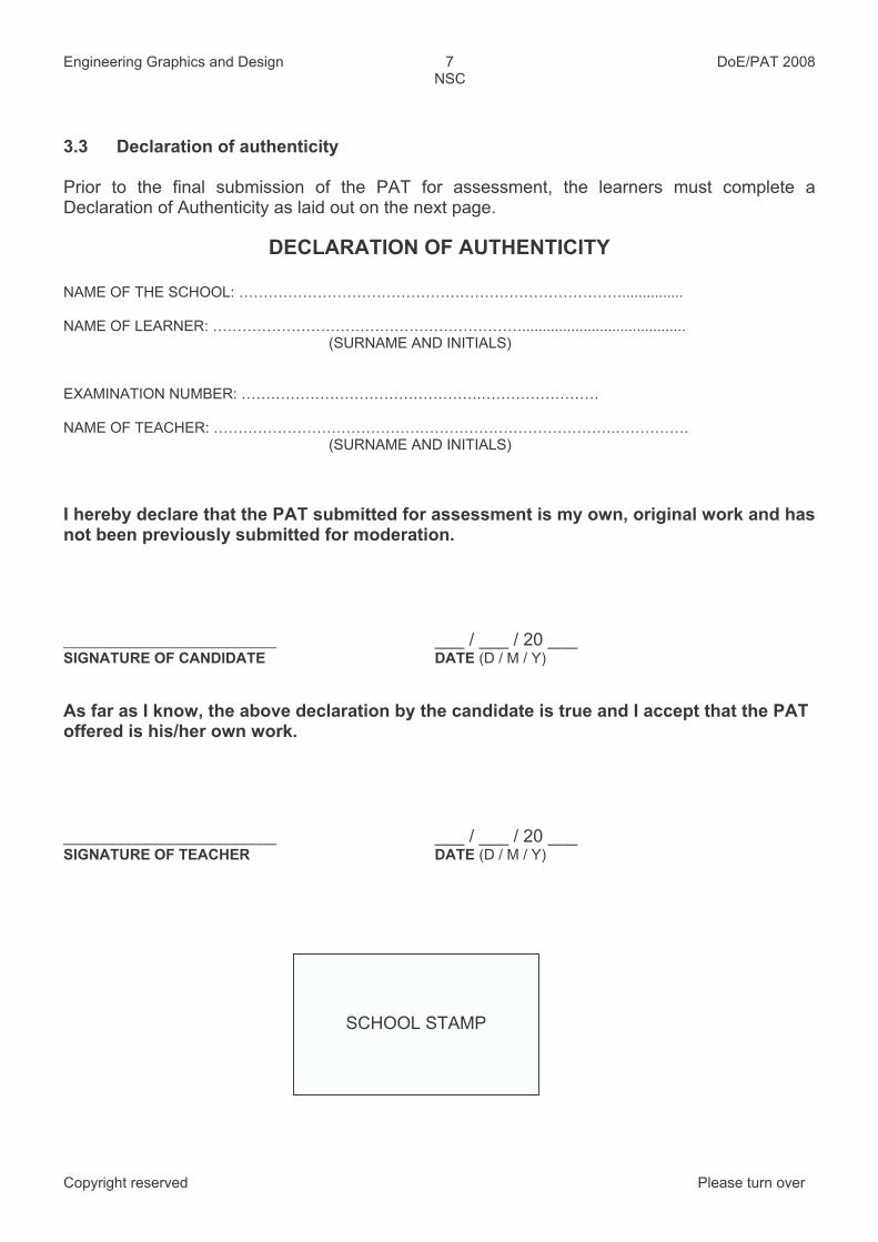
3.3 Declaration of authenticity
Prior to the final submission of the PAT for assessment, the learners must complete a Declaration of Authenticity as laid out on the next page.
DECLARATION OF AUTHENTICITY
NAME OF THE SCHOOL: ……………………………………………………………………...............
NAME OF LEARNER: ………………………………………………………........................................(SURNAME AND INITIALS)
EXAMINATION NUMBER: ………………………………………….……………………
NAME OF TEACHER: ……………………………………………………………………….……………(SURNAME AND INITIALS)
I hereby declare that the PAT submitted for assessment is my own, original work and hasnot been previously submitted for moderation.
__________________________ ___ / ___ / 20 ___ SIGNATURE OF CANDIDATE DATE (D / M / Y)
As far as I know, the above declaration by the candidate is true and I accept that the PAT offered is his/her own work.
__________________________ ___ / ___ / 20 ___ SIGNATURE OF TEACHER DATE (D / M / Y)
SCHOOL STAMP
Copyright reserved Please turn over

Engineering Graphics and Design 8 DoE/PAT 2008 NSC
SECTION B (The Learner Tasks)
Practical Assessment Task 1 Design Project 1 Civil and Electrical
This PAT covers LO1, LO2, LO3 and LO4.
ScenarioYou are presented with the site plan of a corner property in a housing estate where all the houses are built using red face brick and have green corrugated iron roofs. The sight planshows the boundary lengths, building lines and the north point. Refer to figure below.
The plot is level and in the north eastern-corner of the stand is a very old indigenous tree that may not be removed.
The two roads that border the property are Pride Avenue and Hope Street; however, owning ahouse that has access from Hope Street is far more prestigious.
You are required to design a single-storey dwelling with a total floor area not exceeding more than ½ the total area of the stand. The proposed new dwelling must fit in with the finish of theother houses on the estate and comply with the specifications.
BUILDING LINE
40000
30
000
44750
355
50
5000
50
00
HOPE STREET
PR
IDE
AV
EN
VE
ERF 1 OF SUB 47 ERF 3 OF SUB 47
ERF 2 OF SUB 47
3000
3000
SEWAGE LINE
SITE PLAN
SCALE 1:200
Copyright reserved Please turn over

Engineering Graphics and Design 9 DoE/PAT 2008 NSC
Specifications
The proposed new dwelling must have the following rooms. The sizes and positions of the rooms need to be researched/investigated:
Rooms:1 lounge1 dining room 1 kitchen 1 bathroom 2 bedrooms
All window frames and door frames must be timber.
Internal doors must be hollow core and the external doors must be solid timber.
Fixtures:Kitchen: 1 double-bowl sink and kitchen units Bathroom: 1 bath, 1 wash basin, 1 WC Bedrooms: Built-in cupboards in both rooms
Roof:500 mm roof overhangPVC gutters and down pipes
Presentation requirements of the PAT
1. A design brief outlining the needs and specifications 2. Evidence of each stage of the design process3. Detailed freehand sketches used during the design process 4. The minimum drawing requirements as stipulated below 5. A list of all the reference material used in the task (Bibliography) 6. Evidence of evaluation. This could be in the form of reports or sample drawings7. A scale model of the dwelling may be included (Time and facilities permitting)
Drawing requirements of the PAT
1. A set of working drawings showing a minimum of three orthographic views, drawn to a suitable scale. The following three views must be drawn:
A floor plan clearly showing: the positions of all the windows and the doors, room designations and floor finishes, all fixtures and all electrical components and wiring.
An elevation showing the front door, windows, roof and other relevant detail.
A sectional elevation showing the foundation to the roof. 2. An enlarged detailed working drawing of either:
a) The foundation to ceiling; or b) The roofing detail.
3. The site plan with the proposed new dwelling sited with all drainage details. 4. A scale perspective drawing of the proposed new dwelling as seen from Hope Street.
The horizon line must be positioned 1, 6 metres above the ground. 5. All the drawings must be presented on appropriately sized drawing sheets, correctly set up
with borders, name blocks and title strips.6. Penalties will be accrued for untidy and messy work as well as for the late submission of the
task.
Copyright reserved Please turn over
Engineering Graphics and Design 10 DoE/PAT 2008 NSC
The following features should be included on the drawings
Dimensions
Labels, scales, notes and fixture codes
Cutting plane(s)
All hatching detail (colour may be used in accordance with the drawing codes and regulations)
Roof lines and pitch, gutters and down pipes
Total floor areaNOTE: All drawing must comply with the guidelines as contained in the SANS 0143 Code of Practice for Building Drawing and the National Building Regulations.
Drawing methods
The PAT must provide clear evidence that a high level of competency has been attained by thelearners in all the required drawing methods namely:
Freehand drawing (This should include all the preliminary sketch drawings and diagramsproduced during the design process)
Instrument drawing (Pictorial drawing of the dwelling)
Computer-Aided Design system (CAD). (All the working drawings of the dwelling)
NOTE: A period of grace has been extended to those schools that do not have CADfacilities. These schools may complete all drawings using instruments.
Assessment Criteria
The following assessment tools will be used to assess the PAT:
1. The rubric displayed in annexure A for assessing the design process. This mark will contribute 15% to the final PAT mark.
2. The rubric displayed in annexure B for assessing the correctness of the presentationdrawings. This mark will contribute 25% to the final PAT mark.
3. The rubric displayed in annexure C for assessing drawing presentation, drawing methods,quality of line work and printing and meeting deadlines. This mark will contribute 10% to the final PAT mark.
Copyright reserved Please turn over

Engineering Graphics and Design 11 DoE/PAT 2008 NSC
Practical Assessment Task 2 Design Project 2 Mechanical
This PAT covers LO1, LO2, LO3 and LO4.
Scenario
A motor vehicle company has approached you to design a wind tunnel that will be used for testing the aerodynamic properties of their new passenger vehicles in order to try and improve their fuel efficiency. The wind tunnel will be housed in a warehouse at the assembly plant where the floor area measures 40 metres x 30 metres.
Wind tunnel specifications
The tunnel should be constructed from sheet metal. An industrial fan of 1, 5 metres in diameterwill be used to generate the wind. The fan housing must be joined to the test area with an appropriately designed transition piece. As the speed of the wind supplied by the fan will not be sufficient, a non-mechanical feature that can accelerate the wind speed needs to be researched and designed into the wind tunnel.
In order to create the necessary parallel airflow inside the test area, a set of deflectors will alsoneed to be designed and positioned so that accurate measurements can be taken. Also include an access door large enough for a motor vehicle to pass through and an observation window(s) to observe the test area. Another feature in the design must include the immediate outlet at the rear of the test area.
Time and facilities permitting, a scale model of all the components of the wind tunnel may be constructed.
Presentation requirements of the PAT
1. A design brief outlining the needs and specifications 2. Evidence of each stage the design process 3. Detailed freehand sketches used during the design process 4. The minimum drawing requirements as stipulated below 5. A list of all the reference material used in the task (Bibliography) 6. Evidence of evaluation. This could be in the form of reports or sample drawings and 7. A scale model of the wind tunnel may be included (Time and facilities permitting).
Drawing requirements of the PAT
1. A working drawing, with a minimum of three appropriately scaled orthographic views,clearly indicating the positions of all the features making up the wind tunnel. At least one of the views must be a sectional view.
2. Detailed working drawings of the wind speed accelerator and the deflectors for the parallel air flow.
Copyright reserved Please turn over

Engineering Graphics and Design 12 DoE/PAT 2008 NSC
3. Scale developments of the housings of the following features:
The fan housing
The transition pieces
The test area 4. An exploded 3-dimensional pictorial drawing of the components of the wind tunnel. 5. All the drawings must be presented on appropriately sized drawing sheets, correctly set up
with borders, name blocks and title strips.6. Penalties will be accrued for untidy and messy work as well as for late submission of the
task.
The following features should be included on the drawings
Dimensions
Labels, scales, notes
Cutting plane(s)
All hatching detail
Projection symbolNOTE: All drawing must comply with the guidelines contained in the SANS 0111 Code ofpractice for Engineering Drawing.
Drawing methods
The PAT must provide clear evidence that a high level of competency has been attained by thelearners in all three required drawing methods namely:
Freehand drawing (This should include all the preliminary sketch drawings and diagramsproduced during the design process)
Instrument drawing (Pictorial drawing of the wind tunnel)
Computer-Aided Design system (CAD) (All the working drawings of the wind tunnel)
NOTE: A period of grace has been extended to those schools that do not have CADfacilities. These schools may complete all drawings using instruments.
Assessment Criteria
The following assessment tools will be used to assess the PAT:
1. The rubric displayed in annexure A for assessing the design process. This mark will contribute 15% to the final PAT mark.
2. The rubric displayed in annexure B for assessing the correctness of the presentationdrawings. This mark will contribute 25% to the final PAT mark.
3. The rubric displayed in annexure C for assessing drawing presentation, drawing methods,quality of line work and printing and meeting deadlines. This mark will contribute 10% to the final PAT mark.
Copyright reserved Please turn over

Engineering Graphics and Design 13 DoE/PAT 2008 NSC
Practical Assessment Task 3 CAD ApplicationMechanical
This PAT covers LO3 and LO4.
This PAT consists of SECTION A (a 2D component) and SECTION B (an isometric/3Dcomponent). In this PAT both SECTION A and SECTION B must be completed.
SECTION A
The orthographic views of the individual parts of a hinge assembly in third angle orthographic projection as well as an assembled isometric drawing of the hinge assembly are shown below.
ISOMETRIC ASSEMBLY
LIST OF COMPONENTS
NUMBER NAME QUANTITY
1 SHORT LEAF 2
2 LONG LEAF 1
3 PIN 1
114
44
45
Ø20
Ø14
16
23
Ø16
4
16
7
449
0
23
45
R60
R34
Ø16
16
26
47
Ø16
132
LONG LEAF
SHORT LEAF
PIN
R1390
34
R13
Ø20
Ø14
Copyright reserved Please turn over

Engineering Graphics and Design 14 DoE/PAT 2008 NSC
Knowledge and competency requirements for section A of the PAT
1. Set up the drawing interface which must include all the toolbars required to complete the task.
2. Set up a 2D drawing environment which should include:
A minimum of 4 layers with properties assigned to each layer
An A4 drawing sheet with a border and a title strip. 3. Draw, to scale 1:1, and in third-angle orthographic projection the following views of the
assembled parts of the hinge assembly.
The front view
The top view
The right view 4. Once the drawing is complete, scale the views to half the original size and place the
completed drawing on the prepared drawing sheet. 5. Save the drawing. 6. Print the drawing.
The following features must be included on the orthographic drawing
The three orthographic views.
All three views fully dimensioned.
A title and scale placed in the title strip.
The projection symbol. NOTE: All drawing must comply with the guidelines contained in the SANS 0111 Code ofpractice for Engineering Drawing.
SECTION B
Refer to the orthographic views of the individual parts of a hinge assembly and the assembled isometric drawing.
Knowledge and competency requirements for section B of the PAT
1. Set up the drawing interface which must include all the toolbars required to complete the task.
2. Set up a 3D drawing environment which should include:
A minimum of 2 layers with properties assigned to each layer.
An A4 drawing sheet with a border and a name block. 3. Draw an isometric drawing of the assembled hinge or create a 3D model of the assembled
hinge.4. Save the drawing. 5. Print the drawing.
The following features should be included on the isometric/3D drawing
The assembled isometric drawing or the 3D model drawing of the hinge.
The drawing must be orientated the same as shown in the assembled isometric drawing.
The completed name block.
Copyright reserved Please turn over

Engineering Graphics and Design 15 DoE/PAT 2008 NSC
Drawing methods
The PAT must provide clear evidence that a high level of knowledge and drawing competency has been attained in using a CAD system:
Section A: 2D drawing with the orthographic drawing.
Section B: 3D drawing in the form of either an isometric drawing or 3D modelling.
Assessment Criteria
The following assessment tools will be used to assess the CAD PAT:
The rubric displayed in annexure D for assessing CAD knowledge and drawing competency.This mark will contribute 50% to the final PAT mark.
Copyright reserved Please turn over

Engineering Graphics and Design 16 DoE/PAT 2008 NSC
Copyright reserved Please turn over
ANNEXURE A
A RUBRIC FOR ASSESSING THE DESIGN PROCESS
LEVELS OF PERFORMANCE
7 6 5 4 3 2 1CRITERIA
80 –100% 70 - 79% 60 - 69% 50 - 59% 40 - 49% 30 - 39% 0 - 29% Identify the problem
showing a clear understanding of the
scenario
An in-depth and comprehensive
understanding of the scenario is shown.
A thorough understanding of the scenario is shown.
A substantial understanding of the scenario is shown.
A satisfactory understanding of the scenario is shown.
A moderate understanding of the scenario is shown.
An elementary understanding of the scenario is shown.
Shows little to no understanding of the
scenario.
Formulate a design brief listing the
specifications and constraints
An in-depth and comprehensive
understanding of writing the design brief is
shown.
A thorough understanding of writing
the design brief is shown.
A substantial understanding of writing
the design brief is shown.
A satisfactory understanding of writing
the design brief is shown.
A moderate understanding of writing
the design brief is shown.
An elementary understanding of writing
the design brief is shown.
Shows little to no understanding of writing
the design brief.
Research and record possible solutions
Shows evidence of in-depth research resulting
in a wide range of possible solutions, which are clearly,
logically and comprehensively
recorded.
Shows evidence of thorough research
resulting in a range of possible solutions,
which are logically and comprehensively
recorded.
Shows evidence of sound research resulting in a substantial number of possible solutions,
which are clearly recorded.
Shows evidence of adequate research
resulting in a number of possible solutions, which are clearly
recorded.
Shows evidence of moderate research resulting in a limited number of possible solutions, which are
recorded.
Shows evidence of limited research
resulting in a possible solution, which is not
fully recorded
Shows little to no evidence of any
research, or research is irrelevant to the solution.
Select a final solution demonstrating
understanding of the design brief
The final solution shows in depth understanding and complies fully with
the design brief.
The final solution shows thorough understanding and complies fully with
the design brief.
The final solution shows substantial
understanding of the design brief.
The final solution shows satisfactory
understanding of the design brief.
The final solution shows some understanding of
the design brief.
The final solution shows limited understanding of
the design brief.
The final solution shows no understanding of the
design brief.
Show evidence that the researched information
was used
Comprehensive and detailed evidence of the use of the researched
information.
Thorough evidence of the use of the
researched information.
Substantial evidence of the use of the
researched information.
Satisfactory evidence of the use of the
researched information.
Some evidence of the use of the researched
information.
Limited evidence of the use of the researched
information.
No evidence of the use of the researched
information.
Present a complete set of drawings of the selected solution
All the presentation drawings go beyond the minimum requirements and the drawings are all of outstanding quality.
All the presentation drawings go beyond the minimum requirements and the drawings are all of exceptional quality.
All the presentation drawing requirements
are met and the drawings are all of a
very high quality.
All the presentation drawing requirements
are met and the drawings are all of a satisfactory quality.
Some of the presentation drawing requirements are met
and the drawings are of a satisfactory quality.
Some of the presentation drawing requirements are met
and the drawings are all of a poor quality.
The final solution is incomplete and the
drawings are of a poor quality or no drawings
are submitted.
Evaluation
Evidence of comprehensive
evaluation at all stages of the design process is
shown.
Evidence of thorough evaluation at all stages of the design process is
shown.
Evidence of substantial evaluation at most
stages of the design process is shown.
Evidence of adequate evaluation of most
stages of the design process is shown.
Evidence of moderate evaluation at some stages of the design process is shown.
Evidence of limited evaluation at some stages of the design process is shown.
Little or no evidence of any evaluation.

Engineering Graphics and Design 17 DoE/PAT 2008NSC
ANNEXURE B
RUBRIC FOR ASSESSING THE CORRECTNESS OF THE DRAWING
LEVELS OF PERFORMANCE
7 6 5 4 3 2 1
More than minimum requirements Meets minimum requirements Less than minimum requirementsNo drawingpresented
CRITERIA
80 –100% 70 - 79% 60 - 69% 50 - 59% 40 - 49% 30 - 39% 0 - 29%The presentation
contains a top view/plan
The top view/plan meets more than minimum requirements and is totally correct
The front view meets the minimum requirements and is correct.
The front view meets less than minimum requirements and has errors.
Little or no work ispresented
The presentationcontains a front view
/ side view
The front view/side view meets more than minimum requirements and is totally correct
The top view meets the minimum requirements and is correct.
The top view meets less than minimumrequirements and has errors.
Little or no work ispresented
The presentationcontains a sectional
view
The sectional view meets more thanminimum requirements and is totally correct
The sectional view meets the minimumrequirements and is correct.
The sectional view meets less than minimum requirements and has errors.
Little or no work ispresented
Ort
ho
gra
ph
ic d
raw
ing
The presentationcontains a detailed
drawing
The detailed drawing meets more than minimum requirements and is totally correct
The detailed drawing meets the minimumrequirements and is correct.
The detailed drawing meets more than minimum requirements and has errors.
Little or no work ispresented
Correctness of the drawing as a mark*
The correct pictorial drawing method has
been used
The drawing contains more than minimummethod requirements
The drawing contains the minimum method requirements.
The drawing contains less than minimum method requirements.
Little or no work ispresented
The drawing reflectsthe correct size of
the features
The drawing contains more than minimumdimensional requirements.
The drawing contains the minimum dimensional requirements.
The drawing contains less than minimum dimensional requirement.
Little or no work ispresented
P dra
win
gic
toria
l
The drawing is correctly orientated
The drawing is correctly orientated. The drawing is not correctly orientated.Little or no work is
presented
Correctness of the drawing as a mark*
The drawings are correctlyand completely dimensioned
The drawing contains more than minimumdimensional requirements.
The drawing contains the minimum dimensional requirements.
The drawing contains less than minimum dimensional requirement.
Dimensioning is unacceptable
The drawings are well labelled and show all necessary notes
The drawing contains more than minimumlabel and note requirements
The drawing contains the minimum label and note requirements.
The drawing contains less than minimum label and note requirements.
Labels and notesare unacceptable
The drawings display the correct cutting plane(s)
The drawing contains more than minimumcutting plane requirements.
The drawing contains the minimum cutting plane requirements.
The drawing contains less than the minimum cutting plane requirements.
No cutting planesevident.
Copyright reserved Please turn over

Engineering Graphics and Design 18 DoE/PAT 2008NSC
LEVELS OF PERFORMANCE
7 6 5 4 3 2 1
More than minimum requirements Meets minimum requirements Less than minimum requirementsNo drawingpresented
CRITERIA
80 –100% 70 - 79% 60 - 69% 50 - 59% 40 - 49% 30 - 39% 0 - 29%The drawings reflect that
elements in the SABS codes of practice have been used
correctly
The drawing reflects more than minimumrequirements.
The drawing reflects the minimum requirements.
The drawing reflects less than minimum requirements.
Little or no evidence of the use of the
codes of practice.
* The correctness mark is a percentage mark obtained through marking to a memorandum.
Copyright reserved Please turn over

Engineering Graphics and Design 19 DoE/PAT 2008NSC
ANNEXURE C
RUBRIC FOR ASSESSING DRAWING METHOD SKILLS AND PRESENTATION
LEVELS OF PERFORMANCE
7 6 5 4 3 2 1CRITERIA
80 –100% 70 - 79% 60 - 69% 50 - 59% 40 - 49% 30 - 39% 0 - 29%
The page is setup with a border,complete name block and title strip
The page is setup contains more thanminimum requirements.
The page is setup contains the minimum requirements.
The page is setup contains less thanminimum requirements.
Little or no page setup is evident.
The proportion of the features in the drawing
The features showoutstanding proportion
The features showmeritorious proportion
The features showsubstantial proportion
The features showadequate proportion
The features showmoderate proportion
The features showelementary proportion
The features show verylittle or no proportion
The relative size of the features in the drawing
The features showoutstanding relative
size
The features showmeritorious relative
size
The features showsubstantial relative size
The features showadequate relative size
The features showmoderate relative size
The features showelementary relative
size
The features show verylittle or no relative size
Fre
eh
and
dra
win
g
The consistency of line workin the drawing
All line work isoutstanding and
consistent
All line work is verygood and consistent
All line work is goodand consistent
Line work is satisfactoryand consistent
Line work issatisfactory but
inconsistent
Line work is poor andinconsistent
Line work isunacceptable
Drawing presentation as a mark *
The level of competencydisplayed in using
instruments in the drawing
An outstanding displayof competence in
using instruments isshown
A very good display of competence in usinginstruments is shown
A good display of competence in usinginstruments is shown
A satisfactory display of competence in usinginstruments is shown
A moderate display of competence in usinginstruments is shown
A poor display of competence in usinginstruments is shown
Very little or no displayof competence in usinginstruments is shown
The use of correct line typesin the drawing
Line types areoutstanding and
consistent
Line types are verygood and consistent
Line types are goodand consistent
Line types aresatisfactory and
consistent
Line types aresatisfactory but
inconsistent
Line types are poorand inconsistent
Line types areunacceptable
Iru
me
nt
dra
win
gn
st
The consistency of line workin the drawing
Line work isoutstanding and
consistent
Line work is verygood and consistent
Line work is good andconsistent
Line work is satisfactoryand consistent
Line work issatisfactory but
inconsistent
Line work is poor andinconsistent
Line work isunacceptable
Drawing presentation as a mark*
The level of competence displayed in drawing with
CAD system
An outstanding displayof competence in
using CAD is shown
A very good display of competence in using
CAD is shown
A good display of competence in using
CAD is shown
A satisfactory display of competence in using
CAD is shown
A moderate display of competence in using
CAD is shown
A poor display of competence in using
CAD is shown
Very little or no displayof competence in using
CAD is shown
Knowledge of the plotting procedure is shown
An outstandingknowledge of plottingprocedure is shown
A very good knowledge of plottingprocedure is shown
A good knowledge of plotting procedure is
shown
A satisfactory knowledgeof plotting procedure is
shown
A moderate knowledgeof plotting procedure is
shown
A poor knowledge of plotting procedure is
shown
Very little or noknowledge of plottingprocedure is shownC
AD
dra
win
g
Level of file management shown
An outstanding displayof file management is
shown
A very good display of file management is
shown
A good display of filemanagement is shown
A satisfactory display of file management is
shown
A moderate display of file management is
shown
A poor display of filemanagement is shown
Very little or no filemanagement is shown
Drawing presentation as a mark*
All deadlines have been met All drawings handed in
before due dateAll drawings handed
in on due date Most of the drawingshanded in on due date
Some drawings handedin on due date
A few drawings handedin on due date
A drawings handed in on due date
Drawing not handed in on due date
* The drawing presentation mark is a percentage mark obtained through formative assessment
Copyright reserved Please turn over

Engineering Graphics and Design 20 DoE/PAT 2008NSC
ANNEXURE D
A RUBRIC FOR ASSESSING CAD DRAWING SKILLS
LEVELS OF PERFORMANCE
7 6 5 4 3 2 1CRITERIA
80 –100% 70 - 79% 60 - 69% 50 - 59% 40 - 49% 30 - 39% 0 - 29%
Set up a drawinginterface
Shows an in-depth andcomprehensive
understanding of settingup a drawing interface
Shows a thoroughunderstanding of settingup a drawing interface
Shows a substantialunderstanding of settingup a drawing interface
Shows a satisfactoryunderstanding of settingup a drawing interface
Shows a moderateunderstanding of settingup a drawing interface.
Shows an elementaryunderstanding of settingup a drawing interface
Shows little to nounderstanding of settingup a drawing interface
Set up a 2D /3Ddrawing environment
Shows an in-depth andcomprehensive
understanding of settingup a 2D /3D drawing
environment
Shows a thoroughunderstanding of setting
up a 2D /3D drawingenvironment
Shows a substantialunderstanding of setting
up a 2D /3D drawingenvironment
Shows a satisfactoryunderstanding of setting
up a 2D /3D drawingenvironment.
Shows a moderateunderstanding of setting
up a 2D /3D drawingenvironment.
Shows an elementaryunderstanding of setting
up a 2D /3D drawingenvironment
Shows little to nounderstanding of setting
up a 2D /3D drawingenvironment
Set up layers withproperties assigned to
each layer
Shows evidence of in-depth ability to set up
layers and assignproperties to each layer
Shows evidence ofthorough ability to set up
layers and assignproperties to each layer
Shows evidence ofsound ability to set up
layers and assignproperties to each layer
Shows evidence ofadequate ability to setup layers and assign
properties to each layer.
Shows evidence ofmoderate ability to setup layers and assign
properties to each layer.
Shows evidence oflimited ability to set up
layers and assignproperties to each layer
Shows little to no abilityto set up layers andassign properties to
each layer
Set up an A4 drawingsheet with a border and
a title strip
Shows evidence of in-depth ability to set up anA4 drawing sheet with aborder and a title strip
Shows evidence ofthorough ability to set up
an A4 drawing sheetwith a border and a title
strip
Shows evidence ofsound ability to set upan A4 drawing sheet
with a border and a titlestrip
Shows evidence ofadequate ability to set
up an A4 drawing sheet with a border and a title
strip.
Shows evidence ofmoderate ability to set
up an A4 drawing sheet with a border and a title
strip.
Shows evidence oflimited ability to set up an A4 drawing sheet
with a border and a titlestrip
Shows little to no abilityto set up an A4 drawingsheet with a border and
a title strip
Show evidence of the correct use of the
drawing tools
Comprehensive anddetailed evidence isshown of using the
drawing tools correctly
Thorough evidence is shown of using the
drawing tools correctly
Substantial evidence is shown of using the
drawing tools correctly
Satisfactory evidence isshown of using the
drawing tools correctly.
Some evidence isshown of using the
drawing tools correctly.
Limited evidence isshown of using the
drawing tools correctly
No evidence is shown of using the drawing tools
correctly
Show ability to save and retrieve work
Shows evidence of in-depth ability to
save/retrieve work
Shows evidence ofthorough ability tosave/retrieve work
Shows evidence ofsound ability to
save/retrieve work
Shows evidence ofadequate ability tosave/retrieve work.
Shows evidence ofmoderate ability to save/retrieve work.
Shows evidence oflimited ability to
save/retrieve work
Shows little to no abilityto save/retrieve work
Show ability to print Shows evidence of in-
depth ability to ability to print
Shows evidence ofthorough ability to ability
to print
Shows evidence ofsound ability to ability to
Shows evidence ofadequate ability to ability
to print.
Shows evidence ofmoderate ability to
ability to print.
Shows evidence oflimited ability to ability to
Shows little to no abilityto ability to print
The correctness of the 2D/3D drawing as a
mark*80 –100% 70 - 79% 60 - 69% 50 - 59% 40 - 49% 30 - 39% 0 - 29%
* The drawing presentation mark is a percentage mark obtained through formative assessment
Copyright reserved Please turn over

Engineering Graphics and Design 21 DoE/PAT 2008 NSC
Copyright reserved Please turn over
2008 PAT FORMATIVE ASSESSMENTPAT 1 and PAT 2
NAME OF LEARNER: ………………………………………………………... (SURNAME AND INITIALS)
EXAMINATION NUMBER: ………………………………………………………
CRITERIA MARKS CRITERIA MARKS CRITERIA MARKSThe
presentationcontains a front view
The page is set up with a border, complete name block
and title strip
Identify the problem
showing a clear
understandingof the
scenario
Thepresentation
contains a top view
Theproportion of the features
in the drawing
Formulate a design brief listing the
specifications and
constraints
Thepresentationcontains a
sectional view
The relative size of the features in the drawing
Research and record
possiblesolutions
Ort
ho
gra
ph
ic d
raw
ing
Thepresentationcontains a detaileddrawing
Fre
eh
and
dra
win
g
Theconsistency
of line work in the drawing
Correctness of the drawing as a mark*
Drawing presentation as a mark * Select a final
solutiondemonstratingunderstandingof the design
brief
The correct pictorialdrawing
method has been used
The level of competency displayed in
usinginstruments in the drawing
Show evidence that
theresearchedinformationwas used
The drawing reflects the
correct size of the features
The use of correct line types in the
drawing
Pic
torial dra
win
g
The drawing is correctly orientated
Instr
um
ent dra
win
g
Theconsistency
of line work in the drawing
Present a complete set
of drawings of the selected
solutionCorrectness of the drawing as
a mark* Drawing presentation as a
mark*
EvaluationThe drawings are correctly and
well dimensioned
The level of competencedisplayed in using a CAD
system.
The drawings are well labelled and show all necessary notes
Knowledge of the plotting
procedure is shown.
The drawings display the correct cutting plane/s
CA
Dd
raw
ing
Level of file management
shown.
Drawing presentation as a mark*
The drawings reflect that elements in the SABS codes of
Practice have been used correctly
All deadlines have been met.
TOTAL /15 TOTAL /25 TOTAL /10
MODERATED TOTALS
TOTAL /15 TOTAL /25 TOTAL /10
FINAL MARK
/50
FINAL MODERATED MARK
/50
MODERATED BY
Engineering Graphics and Design 22 DoE/PAT 2008 NSC
Copyright reserved Please turn over
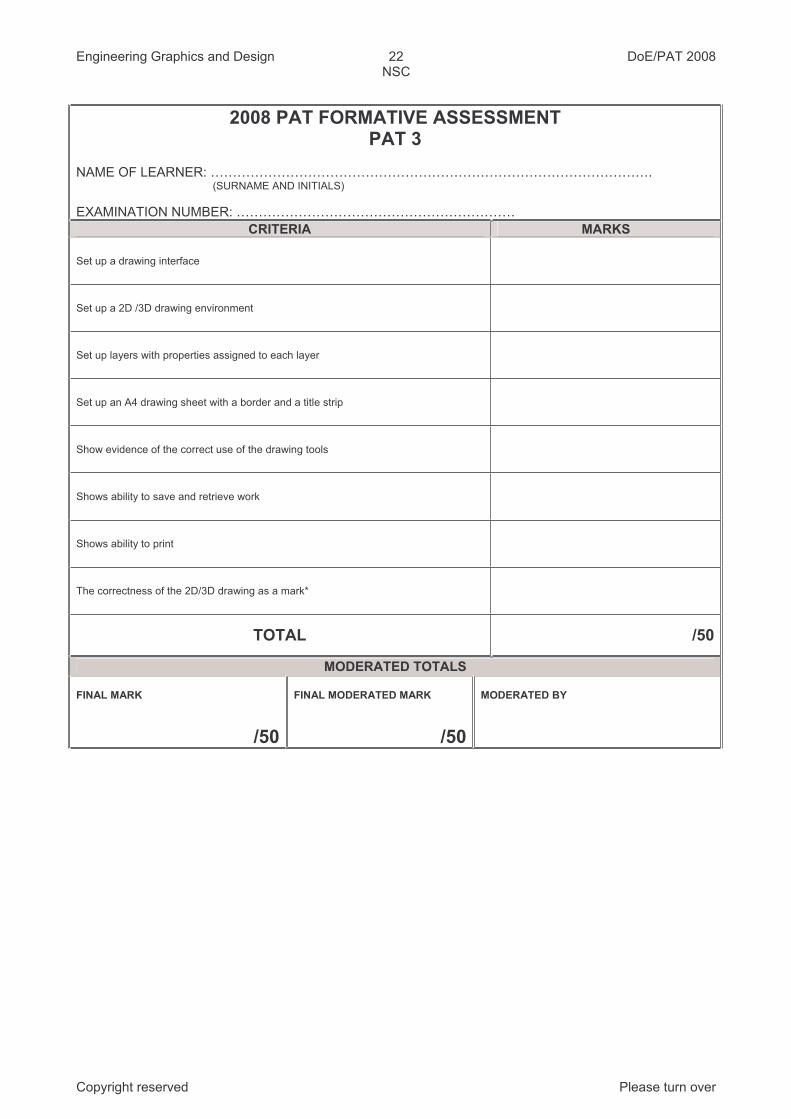
2008 PAT FORMATIVE ASSESSMENTPAT 3
NAME OF LEARNER: ……………………………………………………………………………………….(SURNAME AND INITIALS)
EXAMINATION NUMBER: ………………………………………………………
CRITERIA MARKS
Set up a drawing interface
Set up a 2D /3D drawing environment
Set up layers with properties assigned to each layer
Set up an A4 drawing sheet with a border and a title strip
Show evidence of the correct use of the drawing tools
Shows ability to save and retrieve work
Shows ability to print
The correctness of the 2D/3D drawing as a mark*
TOTAL /50
MODERATED TOTALS
FINAL MARK
/50
FINAL MODERATED MARK
/50
MODERATED BY