Embed Size (px)
Citation preview

Engineering Guidelines Festoon Systems for I-Beams


Conductix-Wampfler – Proven Expertise with Heavy Duty Cable and Hose Trolleys
Whenever materials need to be moved, Conductix-Wampfler can provide customized solutions for flexible energy, data, air, and fluid transmission.
Conductix-Wampfler is well known for its many years of experience and wide know-how in the development and manufacturing of festoon systems.
Heavy Duty trolleys carry flat and round cables for the transmission of electrical energy and data as well as hoses for the transmission of liquids, air or gases.
Conductix-Wampfler festoon systems are used in various applications all over the world, such as steel works, ports, galvanizing lines, bulk material handling, and composting plants.
This engineering guide will assist you with the layout of non-motorized festoon systems and provides the basic data for the calculation of the system.
Content
Components
• Step 1 Selection and arrangement of cables
• Step 2 Selection of the cable trolley program
• Step 3 Calculation of the system
Layout
System illustration
Sizes and units
4
5
6
8
14
16
InfoThis symbol indicates further Information about relevant facts.
3

Figure:0360 Series
Typical Componentsof an I-Beam Cable Trolley
n Cable Support
Function: Support of cables according to minimum bending radii
Design: One-piece (max. stability and bending strength)Material: Steel, hot-dip galvanized
Specificfeature: Riveted nut for easy assembly
n Clamping Bar
Function: Secures the cables on the cable support
Material: Rubber clamping pad Steel, hot-dip galvanized bodySpecificfeature: Segmented to clamp different cable diameters
n Center Plate
Function: Attachment of cable supports, buffers and chassis
Material: Steel, hot-dip galvanized
Specificfeature: For maximum stability
n Side Shield
Function: Arrangement of the rollers in a minimum space
Material: Steel, hot-dip galvanized
Specificfeature: Three-point fixation for optimum distribution of forces
n Main Roller
Function: Allows movement of cable trolley, carries the cable trolley and cable weight
Design: Cylindrical or flanged roller
Material: Steel or polyurethane bandage
Specificfeature: Precision ball bearing lubri- cated for lifetime with addi- tional sealing disk (2RS1)
n Anti-Lift Roller
Function: Protection against lifting, increased protection against tilting
Design: Cylindrical roller
Material: Steel bandage
Specificfeature: Precision ball bearing lubri- cated for lifetime with addi- tional sealing disk (2RS1)
n Horizontal Guide Roller
Function: Precise guidance of the cable trolley
Design: Cylindrical roller
Material: Steel or polyurethane bandage
Specificfeature: Precision ball bearing lubri- cated for lifetime with addi- tional sealing disk (2RS1)
n Large-volume Bumper
Function: Minimize the impact load of the cable trolley
Material: Rubber / polyurethane
Specificfeature: Optimized composition
4

System with Tow trolley
System with Tow clamp
6
2
7
3
4
1
1. Tow trolley/Tow clamp2. Cable trolley3. Cable clamp4. Cables5. Damping device6. Tow rope7. End clamp
SystemIllustration
5
b1 Cable trolley width
b2 Max. permissible clamping width
CE Beam clearance end clamp side
CM Beam clearance tow side
da Cable support diameter
e Free space within storage distance
h Cable loop depth
haCable trolley height from lower edge of beamto upper edge of cable support
hgesCable loop depth from lower edge of beamto loop bottom
k Drill hole distance for tow rope connection
lb Storage distance including free space (e)
lE End clamp length
lges Track beam length
LinstE Installation length end clamp side
LinstM Installation length tow side
lK Tow clamp length
lM Tow trolley length
lMFDistance from middle of tow trolleyto middle of tow trolley twindow
ls Active travel (e.g. main trolley or crane travel)
lw Cable trolley length
5

The larger size power cables (e.g. 4 x 50) should be placed on top of the cable package. This will assure good heat dissipation and proper clamping of the smaller cables.
Dynamic forces that occur as the festoon system moves can be partly absorbed by the larger cables.
n Arrangement of flat cables on the cable support
The flat cable package must be arranged so that all cables are tightly clamped on the cable support and cannot slip.
The cable package should not be too tall in relation to the width. Otherwise the cable package will be unstable and individual, especially smaller cables, will not stay sufficiently clamped.
Layout Step 1Cable Selection and Arrangement
The first steps to lay out a festoon system are:
• Prepare a list of required cables and their cross sections.
• Select the appropriate type of cable (flat or round cable) and the appro-priate composition for the respective application (PVC or Neoprene cable) from our cable offering.
Prior to selecting the required cable trolleys it is important to follow the recommendations listed on the right for the layout of the cable package:
Very good – 100% clamping
Good – 50% clamping
Bad
Whenever possible wider cables should be used instead of multiple smaller cables, e.g.:1 piece of 12 x 1.5 instead of 3 pieces of 4 x 1.5
6
Applies for all cables:Make sure to balance the cable load on the cable support.
n Arrangement of flat cables within the cable clamp
Cable clamps maintain proper spacing of the cable package within the cable loop. The larger diameter power cables (e.g. 4 x 50) are clamped in the upper window; all other cables are guided in the lower windows and can move freely. The arrangement of the cable package must fit properly within the respective clamping window.
Very good
Bad
n Arrangement of round cables on the cable support
The diameters of the round cables should not vary too much in order to allow proper clamping onto the cable support.
Very good
Bad
If deviations in diameters of adjacent cables are more than 15 mm use additional clamping pieces for a proper clamping.
n Arrangement of round cables within the cable clamp
Cable clamps maintain proper spacing of the cable package within the cable loop. The outer cables are clamped; all other cables are guided in the inner windows and can move freely.
Unshielded power cables with larger copper cross sections should be favored for the outer cables (e.g. 1 x 120 or 4 x 25).
Additional spacers can be installed in the cable clamp to avoid overlapping of cables when there are large differences in diameter.
Clamping of shielded (screened)cables should be avoided.
Layout Step 1
Additional clamping piece
Spacer
7

Main rollers with steel wheels
Ø in mm
Travel speed v in m/minup to 63 80 100 125 160 200 250 300
Permissible cable trolley load FLW in kg
40 40 36 3250 75 68 60 5163 125 110 95 85 7580 220 190 162 142 125 110
100 355 305 265 230 200 185 160125 590 550 500 450 410 380 350 310160 1150 1090 1050 1015 990 970 950 925
Layout Step 2Cable Trolley Selection
1 n Determine the cable trolley load (FLW)The approximate cable trolley load (FLW) is determined with the following formula:
FLW = 2 x h x GL
2 n Select the main roller size
Once the approximate cable trolley load (FLW) is determined, the required main roller size can be selected from the following table. The material for the roller is chosen based on operating conditions:
Duty Cycle : ~16h / day Ambient temperature : -30 °C ... +80 °C
Main rollerswith polyurethane wheels
Ø in mm
Travel speed v in m/minup to 63 80 100 125 160 200 250 300
Permissible cable trolley load FLW in kg
40 30 28 2550 60 53 47 4263 110 98 90 80 7080 195 170 155 135 115 100
100 325 280 250 215 185 165 140112 430 395 360 330 305 275 250 210125 540 515 460 410 380 350 320 290160 840 795 750 705 660 615 570 505
Specification MaterialStandard Rollers made of hardened steel
- For low noise emission and low beam wear- In tropical or subtropical climate
Hydrolysis resistant rollers with polyurethane wheelsFLW = cable trolley load in kg
h = cable loop depth in mGL = cable package weight in kg/m
Duty Cycle : ~16h / day Ambient temperature : -30 °C ... +50 °C
8

3 n Determine the cable trolley series
With the size of the main roller selected, the suitable cable trolley program and the possible chassis types can be determined from the following table:
Main rollersØ in mm
vmaxin m/min
Type of cable SeriesPossible chassis types
Track beamParallel flange Tapered flange
40 50 flat/round 0314 S S
40 75 flat 0315 - H
40 100 flat/round 0320 S, SG H, HG, S, SG
50 120 flat/round 0325 S, SG H, HG, S, SG
63 150 flat/round 0330 S, SG H, HG, S, SG
50/63/80/100 160 flat 0350 HF, HFG, S, SG H, HG, HF, HFG, S, SG
50/63/80/100/112/125 160 round 0360 HF, HFG, S, SG H, HG, HF, HFG, S, SG
100/112/125 180 round 0364 HFG HFG
112/125 300* round 0365 HMG, HMP HMG, HMP
125/160 210 flat 0370 HMG, HMP HMG, HMP
125/160 300* round 0375 HMG, HMP HMG, HMP
125/160 300 round 0380 HMG, HMP -
160 300 round 0385 HMG, HMP -
Chassis type overview see next page >>>
* in combination with motorized systems nn Motorized programs highlighted in gray
n Minimum beam dimension
The following beam dimensions are necessary to accommodate the trolley wheel diameter.
( )4roller-Ø + r + s + 10Minimum beam width bmin in mm = 2 x
Air gap A (between main roller and beam flange) = min. 10 mm rolle
r-Ø
Layout Step 2
9

4 n Select the chassis type
TypeH
Chassis with cylindrical main rollersGuidance of the chassis at the radius of the beam web
• For simple applications with low lateral forces
• Not suitable for tow trolleys
Guidance of the chassis simple optimalProtection against tilting low highProtection against lifting low highWear of beam/rollers high low
TypeHG
Chassis with cylindrical main rollersand anti-lift rollersGuidance of the chassis at the radius of the beam web
• For simple applications with low to medium lateral forces and tilting torques
• Suitable for tow trolleys
Guidance of the chassis simple optimalProtection against tilting low highProtection against lifting low highWear of beam/rollers high low
Standard application dataI-beam tapered flange
Beam width max. 100 mm
Travel speed < 120 m/min
Main roller material steel, polyurethane
Standard application dataI-beam tapered flange
Beam width max. 100 mm
Travel speed < 120 m/min
Main roller material steel, polyurethane
TypeHF
Chassis with cylindrical main rollersand horizontal guide rollersGuidance of the chassis at the beam flange
• For applications with low to medium lateral forces
• Not suitable for tow trolleys
Guidance of the chassis simple optimalProtection against tilting low highProtection against lifting low highWear of beam/rollers high low
Standard application dataI-beam parallel/tapered flange
Beam width max. 140 mm
Travel speed < 150 m/min
Main roller material steel, polyurethane
10
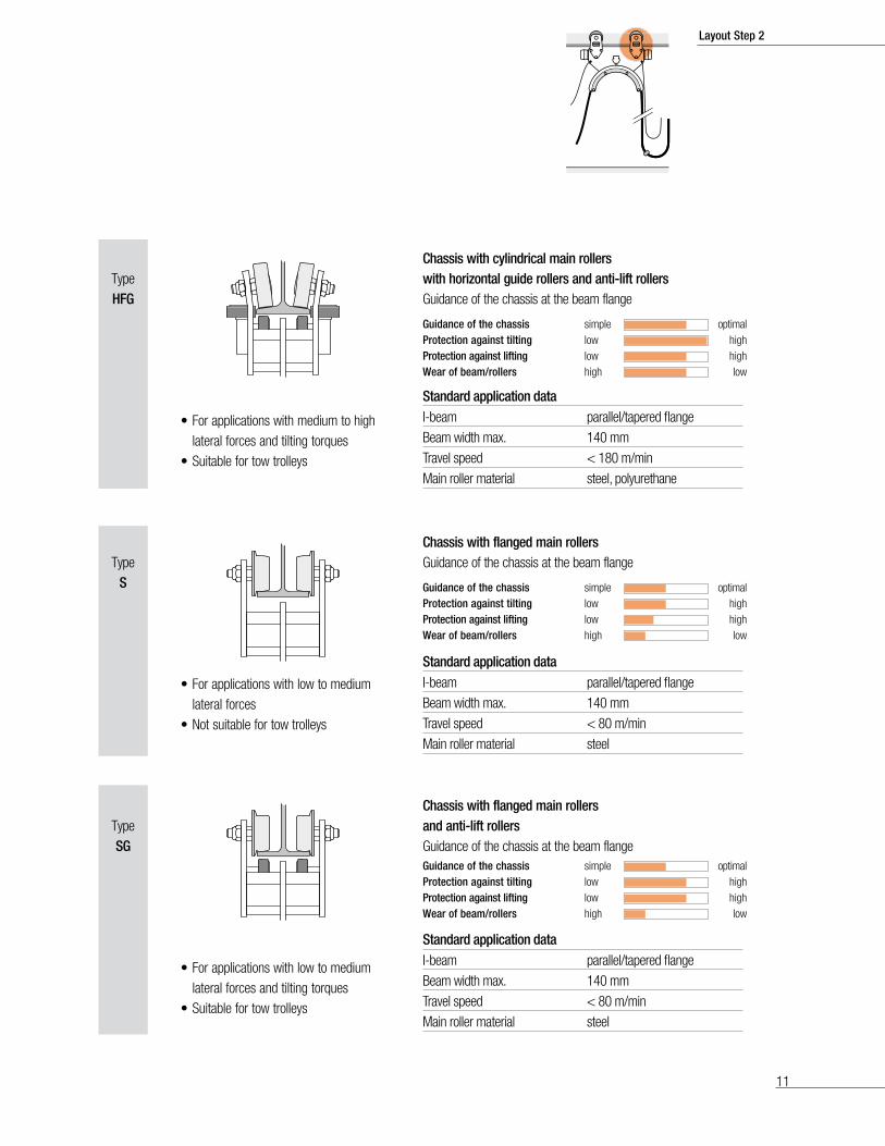
Chassis with cylindrical main rollerswith horizontal guide rollers and anti-lift rollersGuidance of the chassis at the beam flange
TypeHFG
• For applications with medium to high lateral forces and tilting torques
• Suitable for tow trolleys
Guidance of the chassis simple optimalProtection against tilting low highProtection against lifting low highWear of beam/rollers high low
TypeS
Chassis with flanged main rollersGuidance of the chassis at the beam flange
• For applications with low to medium lateral forces
• Not suitable for tow trolleys
Guidance of the chassis simple optimalProtection against tilting low highProtection against lifting low highWear of beam/rollers high low
Standard application dataI-beam parallel/tapered flange
Beam width max. 140 mm
Travel speed < 180 m/min
Main roller material steel, polyurethane
Standard application dataI-beam parallel/tapered flange
Beam width max. 140 mm
Travel speed < 80 m/min
Main roller material steel
TypeSG
Chassis with flanged main rollersand anti-lift rollersGuidance of the chassis at the beam flange
• For applications with low to medium lateral forces and tilting torques
• Suitable for tow trolleys
Guidance of the chassis simple optimalProtection against tilting low highProtection against lifting low highWear of beam/rollers high low
Standard application dataI-beam parallel/tapered flange
Beam width max. 140 mm
Travel speed < 80 m/min
Main roller material steel
Layout Step 2
11

4 n Select the chassis type
TypeHMG
Chassis with cylindrical main rollers with horizontal guide rollers at the beam center web and anti-lift rollersGuidance of the chassis at the beam center web
• For applications under very difficult conditions (e.g. STS container cranes)
• Suitable for tow trolleys
Guidance of the chassis simple optimalProtection against tilting low highProtection against lifting low highWear of beam/rollers high low
TypeHMP
Chassis with cylindrical main rollers withhorizontal guide rollers at the beam center web and anti-lift plateGuidance of the chassis at the beam center web
• For applications with motorized cable trolleys and heavy cable packages
• Suitable for tow trolleys
Guidance of the chassis simple optimalProtection against tilting low highProtection against lifting low highWear of beam/rollers high low
Standard application dataI-beam parallel/tapered flange
Beam width max. 200 mm
Travel speed < 300 m/min
Main roller material polyurethane
Standard application dataI-beam parallel/tapered flange
Beam width max. 200 mm
Travel speed < 300 m/min
Main roller material polyurethane
12

Ø da
5 n Determine the cable support diameter
To determine the required cable support diameter da, calculations must be performed based on the cables being installed.
The smallest permissible cable support diameter da is determined on the basis of the largest cables:
Example of calculation flat cable:
Example of calculation round cable:
The thickness SFL of the largest flat cable is 13 mm
Accordingly the minimum support diameter is:da = 10 x 13 mm = 130 mm
The outer diameter dRL of the largest round cable is 20 mm
Accordingly the minimum support diameter is:da = 10 x 20 mm = 200 mm
Thickness of flat cable SFL ≤ 12.5 mm
Thickness of flat cableSFL ≥ 12.5 mm
Outer diameter of round cabledRL = outer diameter
Min support-Øda in mm
8 x SFL 10 x SFL 10 x dRL
S FL d RL
S FL d RL
Layout Step 2
13

2 x h + 1.25 x da - f x lW
f x (ls + e)n =
Layout Step 3Calculate the system
1 n Determine the number of loopsFirst define the cable loop depth h, then choose the additional cable length factor f from the table below.
n = Number of loopsls = Active travel in mf = Additional cable length factor (see table below)h = Cable loop depth in mda = Cable support diameter in mlW = Cable trolley length in me = Free space in storage distance (recommendation ≥ 0.5 m)
nn For the cells highlighted in orange we recommend the use of damping devices or motorized systems to stabilize the cable loops.
nn Motorized programs highlighted in gray.
2 n Determination of the required storage distance from middle of end clamp to middle of tow trolleyFor further calculations round up the number of loops.
lb = (n-1) x lW + lE +lM + e
lb = Storage distance from middle of end clamp to middle of tow trolley in mn = Number of loopslW = Length of cable trolley in mlE = Length of end clamp in mlM = Length of tow trolley/ tow clamp in me = Free space in storage distance (recommendation ≥ 0.5 m)
3 n Determination of the cable system length from middle of end clamp to middle of tow trolley and of the order length of the cable
LBest = LSyst + LinstE + LinstM
LSyst = Required cable system length from middle of end clamp to middle of tow trolley/tow clamp in mf = Additional cable length factorls = Active travel in mlb = Storage distance in mLinstE = Installation length end clamp side in mLinstM = Installation length tow side in mLBest = Cable order length, including installation length - in m
LSyst = f x (ls + lb)
Additional length factor f Cable loop depth h in mTravel speedvmax in m/min
< 0.8 0.8 - 1.2 1.3 - 2.0 2.1 - 3.2 3.3 - 5.0 5.1 - 8.0
32 1.10 1.10 1.10 1.10 1.10 1.1033 - 40 1.15 1.10 1.10 1.10 1.10 1.1041 - 50 1.20 1.15 1.10 1.10 1.10 1.1051 - 63 1.25 1.20 1.15 1.10 1.10 1.1064 - 80 1.25 1.20 1.15 1.10 1.1081 - 100 1.25 1.20 1.15 1.10
101 - 125 1.25 1.20 1.15126 - 160 1.25 1.25 1.20161 - 200 1.25 1.25 1.25201 - 250 1.25 1.25 1.25251 - 300 1.25 1.25 1.25
n Determination of the additional cable length factor f
n determines the number of required cable trolleys:
Number of cable trolleys = n-1
14

4 n Determine the actual cable loop
h = Cable loop depthLSyst = Required cable system length measured from middle of end clamp to middle of tow trolley or tow clamp in mda = Cable support diameter in mn = Number of loops
2 x nLSysth = - (0.63 x da)
5 n Determine the tow rope lengths
For travel speeds higher than50 m/min, we recommend the use of tow ropes.
Please take the dimension k for the tow rope fixation from the respective cable trolley program.
nLSyst - (k + 0.084)LZug = 0.95 x
6 n Select damping device
LGum = Shock cord length in mLZug = Tow rope length in m
1.5LZugLGum =
The selection of the correct damping device (quantity and diameter of the shock cords) depends on the application.– Please contact us –
Layout Step 3
15

Symbols and Units
b1 mm Cable trolley width
b2 mm Max. permissible clamping width
cE m, mm Beam clearance end clamp side
cM m, mm Beam clearance tow side
da mm Cable support diameter
dRL mm Outer diameter round cable
e m, mm Free space within the storage distance
f Additional cable factor length
FLW kg Cable trolley load
GL kg/m Cable package weight
h m, mm Cable loop depth
ha m, mm Cable trolley height from lower edge of beam to upper edge of cable support
hges m Cable loop depth from lower edge of beam to loop bottom
k m, mm Drill hole distance for tow rope connection
lb m Cable trolley storage including free space (e)
LBest m Cable order length
lE m, mm End clamp length
lges m Track beam length
LGum m Shock cord length
LinstE m Installation length end clamp side
LinstM m Installation length tow side
lK m, mm Tow clamp length
lM m, mm Tow trolley length
lMF m, mm Distance from middle of tow trolley to middle of tow trolley window
ls m Active travel (e.g. main trolley or crane travel)
LSyst m Cable system length
lW m, mm Cable trolley length
LZug m Tow rope length
n Number of loops
s mm Clamping height at the cable trolley
sFL mm Thickness of flat cable
v m/s, m/min Travel speed
16
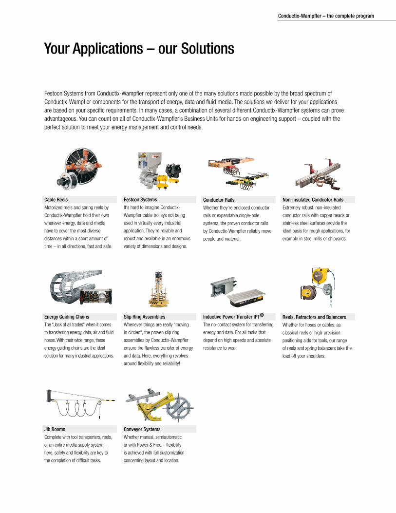
Your Applications – our Solutions
Festoon Systems from Conductix-Wampfler represent only one of the many solutions made possible by the broad spectrum of Conductix-Wampfler components for the transport of energy, data and fluid media. The solutions we deliver for your applications are based on your specific requirements. In many cases, a combination of several different Conductix-Wampfler systems can prove advantageous. You can count on all of Conductix-Wampfler’s Business Units for hands-on engineering support – coupled with the perfect solution to meet your energy management and control needs.
Jib Booms
Complete with tool transporters, reels,
or an entire media supply system –
here, safety and flexibility are key to
the completion of difficult tasks.
Conductor Rails
Whether they‘re enclosed conductor
rails or expandable single-pole
systems, the proven conductor rails
by Conductix-Wampfler reliably move
people and material.
Non-insulated Conductor Rails
Extremely robust, non-insulated
conductor rails with copper heads or
stainless steel surfaces provide the
ideal basis for rough applications, for
example in steel mills or shipyards.
Cable Reels
Motorized reels and spring reels by
Conductix-Wampfler hold their own
wherever energy, data and media
have to cover the most diverse
distances within a short amount of
time – in all directions, fast and safe.
Festoon Systems
It‘s hard to imagine Conductix-
Wampfler cable trolleys not being
used in virtually every industrial
application. They‘re reliable and
robust and available in an enormous
variety of dimensions and designs.
Reels, Retractors and Balancers
Whether for hoses or cables, as
classical reels or high-precision
positioning aids for tools, our range
of reels and spring balancers take the
load off your shoulders.
Inductive Power Transfer IPT®
The no-contact system for transferring
energy and data. For all tasks that
depend on high speeds and absolute
resistance to wear.
Slip Ring Assemblies
Whenever things are really “moving
in circles“, the proven slip ring
assemblies by Conductix-Wampfler
ensure the flawless transfer of energy
and data. Here, everything revolves
around flexibility and reliability!
Energy Guiding Chains
The “Jack of all trades“ when it comes
to transferring energy, data, air and fluid
hoses. With their wide range, these
energy guiding chains are the ideal
solution for many industrial applications.
Conveyor Systems
Whether manual, semiautomatic
or with Power & Free – flexibility
is achieved with full customization
concerning layout and location.
Conductix-Wampfler – the complete program

Contact us for our Global Sales Offices
KAT0
300-
0101
a-US
© C
ondu
ctix-
Wam
pfler
| 20
13 |
subj
ect t
o te
chni
cal m
odifi
catio
ns w
ithou
t prio
r not
ice USA / LATIN AMERICA
10102 F Street
Omaha, NE 68127
Customer Support
Phone +1-800-521-4888
Fax +1-800-780-8329
Phone +1-402-339-9300
Fax +1-402-339-9627
CANADA
175 Blvd JF Kennedy
St. Jérôme, QC J7Y 4B5
Customer Support
Phone +1-800-667-2487
Fax +1-800-442-9817
Phone +1-450-565-9900
Fax +1-450-432-6985
MÉXICO
Calle Treviño 983-C
Zona Centro
Apodaca, NL México 66600
Customer Support
Phone (+52 81) 1090 9519
(+52 81) 1090 9025
(+52 81) 1090 9013
Fax (+52 81) 1090 9014
BRAZIL
Rua Luiz Pionti, LT 05, QD.
L - Vila Progresso
Itu, São Paulo, Brasil
CEP: 13.313-534
Customer Support
Phone (+55 11) 4813 7330
Fax (+55 11) 4813 7330
www.conductix.us