Embed Size (px)
Citation preview

Importance of properly sizing valves
It is important to properly size a valve. There are undesirable effects in both undersizing and oversizing.
Undersizing may result in:
1) the inability to meet desired flow require-ments
2) the flashing of liquids to vapours on the outlet side of the valve
3) a fall in the outlet pressure4) substantial pressure losses in the piping
system
Oversizing may result in:
1) unnecessary cost of oversized equip-ment
2) variable flow through the valve or erratic control of the flow
3) shorter life of some valve designs through oscillating of internal parts to maintain required internal pressure differentials, caused by lack of flow
4) erratic operation of some designs such as failure to shift position due to lack of required flow in 3- and 4-way valves
5) erosion or wire drawing of seats in some designs because they operate in the nearly closed position
Definition of Kv
The flow coefficient Kv in cubic metres per hour or litres per minute is a special volu-metric flow rate (capacity) through a valve at a specified travel and at the following conditions:
- the static pressure loss (∆pKv) across the valve is 105 Pa (1 bar)
- the fluid is water within a temperature range of 278 K to 313 K (5°C to 40°C)
- the unit of the volumetric flow rate is cubic metre per hour or litres per minute
The Kv value can be obtained from test results with the help of the following equa-tion:
Kv Qpp
Kv
w
= ∆∆
. .
ρρ
where:Q is the measured volumetric flow rate
in cubic metres per hour or litres per minute
∆pKv is the static pressure loss of 105 Pa (see above)
∆p is the measured static pressure loss across the valve in pascals
If the drop is less than assigned minimum differential, the valve is oversized. In these situations, a valve with a lower minimum operating pressure differential should be employed or, alternatively, a smaller sized valve with a more closely defined Kv factor.
The formulas necessary to determine the Kv are quite complicated and for that reason a series of flow graphs was developed which reduce that problem to one of a simple multiplication or division.
All flow calculations for a fluid have been simplified to a basic formula:
Kv = ---------------------Flow required: Q
Graph factors: Fgm, Fsg, Fgl
The graph factors Fgm, Fsg, Fgl can be easily picked out by aligning known pressure con-ditions on the graphs I to X on the following pages (for calculations see next page).
The tables below can be used to estimate a Kv if the orifice size is known, or to relate the approximate orifice size if the Kv is known. The chart is based on the ASCO design of in-line globe type valves. The flow charts must be used for precise sizing and converting Kv factors to actual flow terms, and the catalogue page must be consulted for the actual Kv of a particular valve.
Approx. orifice size
approx. KvApprox. orifice size
approx. Kv
(mm) (m³/h) (l/min) (mm) (m³/h) (l/min)
0,8
1,2
1,6
2,4
3,2
3,6
4,8
6,4
8
9
0,02
0,05
0,08
0,17
0,26
0,31
0,45
0,60
1,5
1,7
0,33
0,83
1,33
2,83
4,33
5,17
7,50
10,0
25,0
28,3
13 3 50,0
16 4 66,7
18 4,5 75,0
19 6,5 108
25 11 183
32 15 250
38 22 366
51 41 683
64 51 850
76 86 1433
80 99 1650
100 150 2500
125 264 4400
150 383 6375
ρ is the density of the fluid in kilograms per cubic metre
ρw is the density of water (see above) in kilograms per cubic metre (according to IEC 534)
Conditions to be known
In general, we must know as many of the conditions surrounding the application as possible.
Flow required in cubic metres per hour (m3/h) for liquids, normal cubic metres per hour (nm3/h) for gases, or kilograms per hour (kg/h) for steam. These figures can be obtained by simply asking the customer's requirements or referring to the nameplates on pumping equipment, boiler room charts or calculations.
Inlet Pressure (p1) - This is usually obtained from the source of the supply or by placing a pressure gauge near the valve inlet.
Outlet Pressure (p2) - This can be obtained by gauge observations, but usually is tied in with specifications regarding allowable system pressure drop. If we know the inlet pressure and the pressure drop, then the outlet pressure is easy to determine.
Pressure Drop (∆p) - In large or complicated systems, it is desirable to keep the pressure drop across a valve to a minimum, and often the customer will have definite specifications concerning the factor. Of course, if the valve is discharging to atmosphere, the pressure drop is equal to the inlet pressure when deal-ing with liquids. However, when sizing valves for use with gases and steam, although the valve may be discharging to atmosphere, only 50 percent of the inlet pressure can be used for the pressure drop used in the formulas (commonly called critical pressure drop). In all other cases, the pressure drop is the difference between inlet and outlet pressures.
Note: It is often difficult to understand the meaning of the term "minimum operating pressure differential" (see page V045).
Certain pilot operated valves function by differential pressures created internally by "pilot" and "bleed" arrangements. This differential is measured as the difference between inlet and outlet conditions on all valve construction. If pressure conditions are not known, but only flow information, we can use the graphs or formulas to solve the resulting pressure drop.
ENGINEERING INFORMATIONFlow data,
flow factor and orifice size
0001
1GB
-201
6/R
01A
vaila
bilit
y, d
esig
n an
d sp
ecifi
catio
ns a
re s
ubje
ct to
cha
nge
with
out n
otic
e. A
ll rig
hts
rese
rved
.
All leaflets are available on: www.asco.com
V050-1
A
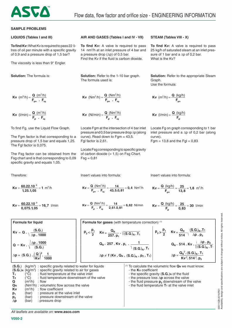
AIR AND GASES (Tables I and IV - VII)
To find Kv: A valve is required to pass 14 nm3/h at an inlet pressure of 4 bar and a pressure drop (∆p) of 0,5 bar.Find the Kv if the fluid is carbon dioxide.
Solution: Refer to the 1-10 bar graph.The formula used is:
Kv QF Fgm sg
.
(Nm /h)(Nm /h)3
3
=
Kv QF Fgl sg
.
(Nl/min)(Nm /h)3
=
Locate Fgm at the intersection of 4 bar inlet pressure and 0,5 bar pressure drop ∆p (along curve). Read down to Fgm = 43,5.Fgl factor is 2,61.
Locate Fsg corresponding to specific gravity of carbon dioxide (= 1,5) on Fsg Chart.Fsg = 0,81
Insert values into formula:
Kv QF Fgm sg
= = = . , . ,
, (Nm /h)Nm /h
3314
43 5 0 810 4
Kv QF Fgl sg
= = = . , . ,
, (Nm /h)Nl/min
3 142 61 0 81
6 62
STEAM (Tables VIII - X)
To find Kv: A valve is required to pass 25 kg/h of saturated steam at an inlet pres-sure of 1 bar and a ∆p of 0,2 bar.What is the Kv?
Solution: Refer to the appropriate Steam Graph.Use the formula:
Kv QFgm
(m /h)
(kg/h)3 =
Kv QFgl
(l/min)
(kg/h)=
Locate Fg on graph corresponding to 1 bar inlet pressure and a ∆p of 0,2 bar (along curve).Fgm = 13,8 and the Fgl = 0,83
Insert values into formula:
Kv QFgm
= = = ,
, (kg/h)m /h325
13 81 8
Kv QFgl
= = = ,
(kg/h)l/min25
0 8330
SAMPLE PROBLEMS
LIQUIDS (Tables I and III)
To find Kv: What Kv is required to pass 22 li-tres of oil per minute with a specific gravity of 0,9 and a pressure drop of 1,5 bar?
The viscosity is less than 9° Engler.
Solution: The formula is:
Kv QF Fgm sg
.
(m /h)(m /h)3
3 =
Kv QF Fgl sg
.
(l/min)(m /h)3
=
To find Fg, use the Liquid Flow Graph.
The Fgm factor is that corresponding to a pressure drop of 1,5 bar and equals 1,25.The Fgl factor is 0,075.
The Fsg factor can be obtained from the Fsg chart and is that corresponding to 0,09 specific gravity and equals 1,05.
Therefore:
Kv = =−60 22 10
1 25 1 051
3. ., . ,
m /h3
Kv = =−60 22 10
0 075 1 0516 7
3. ., . ,
, l/min
Flow data, flow factor and orifice size - ENGINEERING INFORMATION
Formula for liquid Formula for gases (with temperature correction) (1)
(S.G.) (kg/m3) : specific gravity related to water for liquids (S.G.)N (kg/m3) : specific gravity related to air for gasesT1 (°C) : fluid temperature at the valve inletT2 (°C) : fluid temperature downstream of the valveQ (m3/h) : flowQN (Nm3/h) : volumetric flow across the valveKv (m3/h) : flow coefficientp1 (bar) : pressure at the valve inletp2 (bar) : pressure downstream of the valveDp (bar) : pressure drop
(1) To calculate the volumetric flow QN we must know: - the KV coefficient - the specific gravity (S.G.)N of the fluid - the pressure loss Dp across the valve - the fluid pressure p2 downstream of the valve - the fluid temperature T1 at the valve inlet
0001
1GB
-201
6/R
01A
vaila
bilit
y, d
esig
n an
d sp
ecifi
catio
ns a
re s
ubje
ct to
cha
nge
with
out n
otic
e. A
ll rig
hts
rese
rved
.
All leaflets are available on: www.asco.com
V050-2
0,03
0,48
0,54
0,42
0,36
0,30
0,18
0,12
0,06
0
0,24
Specific gravity (S.G.)
Fact
or F
sg
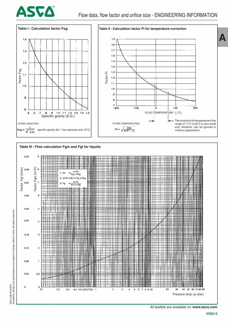
Table I : Calculation factor Fsg Table II : Calculation factor Ft for temperature correction
The correction for temperature in the range of -7°C to 65°C is very small and, therefore, can be ignored in ordinary applications
Fact
or F
t
Fact
or F
gm (
m3 /
h)
Fact
or F
gl (
l/min
)
Table III : Flow calculation Fgm and Fgl for liquids
Pressure drop ∆p (bar)
FLUID TEMPERATURE t2 (°C)
OTHER TEMPERATURESOTHER GRAVITIES
specific gravity (for 1 bar absolute and 15°C)
Flow data, flow factor and orifice size - ENGINEERING INFORMATION00
011G
B-2
016/
R01
Ava
ilabi
lity,
des
ign
and
spec
ifica
tions
are
sub
ject
to c
hang
e w
ithou
t not
ice.
All
right
s re
serv
ed.
A
All leaflets are available on: www.asco.com
V050-3
0,17 0,18 0,21 0,24 0,27 0,30 0,36 0,42 0,48 0,54
Factor Fgm (m3/h)
0,42 1,56 1,680,24 0,30 0,36 0,480,54
0,60,66
0,720,78
0,840,9
0,961,02
1,081,14
1,21,26
1,321,38
1,441,5 1,62 1,74
1,81,86
1,921,98
2,042,1
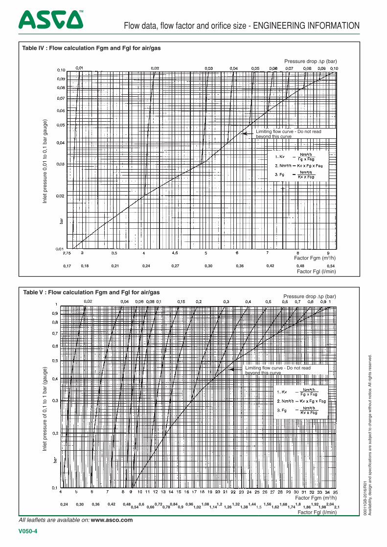
Table IV : Flow calculation Fgm and Fgl for air/gas
Limiting flow curve - Do not readbeyond this curve
Inle
t pre
ssur
e 0,
01 to
0,1
bar
gau
ge)
Limiting flow curve - Do not read beyond this curve
Factor Fgm (m3/h)
Factor Fgl (l/min)
Pressure drop ∆p (bar)Table V : Flow calculation Fgm and Fgl for air/gas
Pressure drop ∆p (bar)
Inle
t pre
ssur
e of
0,1
to 1
bar
(ga
uge)
Factor Fgl (l/min)
Flow data, flow factor and orifice size - ENGINEERING INFORMATION
0001
1GB
-201
6/R
01A
vaila
bilit
y, d
esig
n an
d sp
ecifi
catio
ns a
re s
ubje
ct to
cha
nge
with
out n
otic
e. A
ll rig
hts
rese
rved
.
All leaflets are available on: www.asco.com
V050-4
3,6 7,8 1,081,029,698,47,26,665,44,84,23,02,41,81,20,6
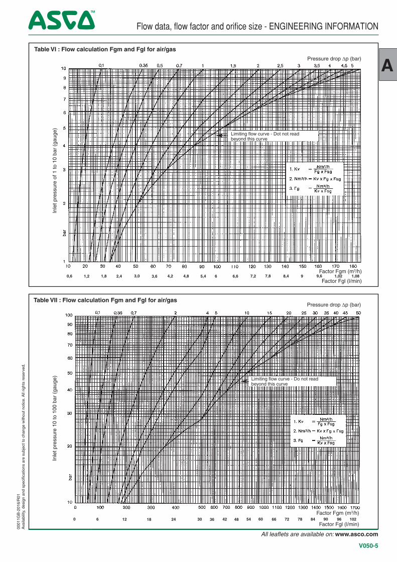
Table VI : Flow calculation Fgm and Fgl for air/gas
Limiting flow curve - Dot not read beyond this curve
Factor Fgl (l/min)
Pressure drop ∆p (bar)In
let p
ress
ure
of 1
to 1
0 ba
r (g
auge
)In
let p
ress
ure
10 to
100
bar
(ga
uge)
Table VII : Flow calculation Fgm and Fgl for air/gas
48 102969084787266605442363024181260Factor Fgm (m3/h)
Factor Fgl (l/min)
Pressure drop ∆p (bar)
Limiting flow curve - Do not read beyond this curve
Factor Fgm (m3/h)
Flow data, flow factor and orifice size - ENGINEERING INFORMATION00
011G
B-2
016/
R01
Ava
ilabi
lity,
des
ign
and
spec
ifica
tions
are
sub
ject
to c
hang
e w
ithou
t not
ice.
All
right
s re
serv
ed.
A
All leaflets are available on: www.asco.com
V050-5
0,54 0,78 1,681,621,561,51,441,381,321,261,21,141,081,020,96
0,90,840,72
0,660,60,48
0,420,36
0,30,24
0,18
9,68,47,87,26,66,05,44,84,23,63,02,41,81,20,60
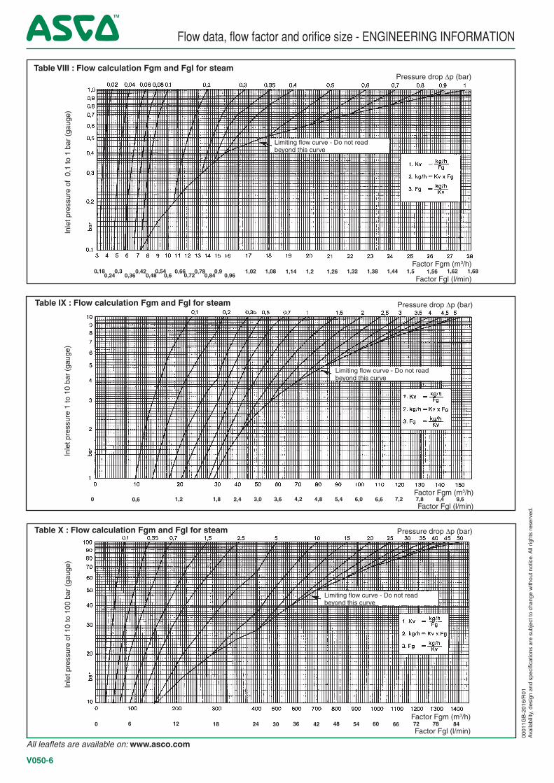
Table VIII : Flow calculation Fgm and Fgl for steam
Factor Fgm (m3/h)
Factor Fgl (l/min)
Limiting flow curve - Do not read beyond this curve
Pressure drop ∆p (bar)In
let p
ress
ure
of 0
,1 to
1 b
ar (
gaug
e)
Factor Fgm (m3/h)
Factor Fgl (l/min)
Limiting flow curve - Do not read beyond this curve
Inle
t pre
ssur
e 1
to 1
0 ba
r (g
auge
)
Pressure drop ∆p (bar)
8478726660544842363024181260
Limiting flow curve - Do not read beyond this curve
Factor Fgm (m3/h)
Factor Fgl (l/min)
Pressure drop ∆p (bar)Table X : Flow calculation Fgm and Fgl for steam
Table IX : Flow calculation Fgm and Fgl for steam
Inle
t pre
ssur
e of
10
to 1
00 b
ar (
gaug
e)
Flow data, flow factor and orifice size - ENGINEERING INFORMATION
0001
1GB
-201
6/R
01A
vaila
bilit
y, d
esig
n an
d sp
ecifi
catio
ns a
re s
ubje
ct to
cha
nge
with
out n
otic
e. A
ll rig
hts
rese
rved
.
All leaflets are available on: www.asco.com
V050-6
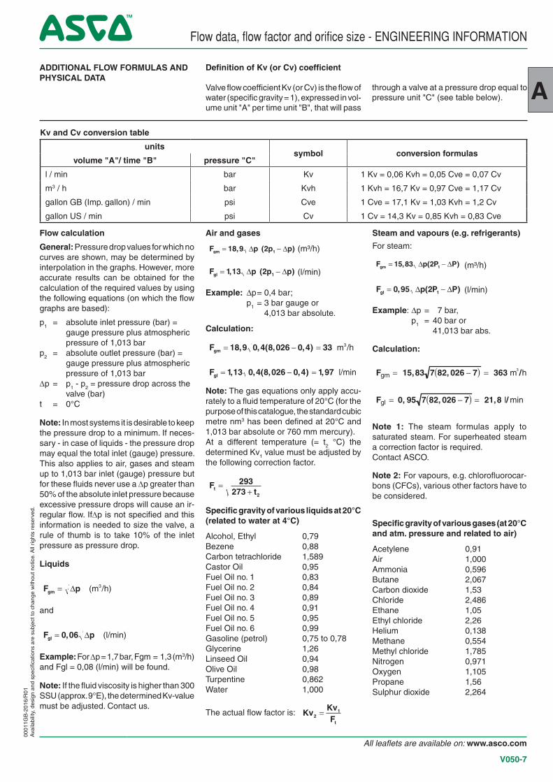
through a valve at a pressure drop equal to pressure unit "C" (see table below).
Flow calculation
General: Pressure drop values for which no curves are shown, may be determined by interpolation in the graphs. However, more accurate results can be obtained for the calculation of the required values by using the following equations (on which the flow graphs are based):
p1 = absolute inlet pressure (bar) = gauge pressure plus atmospheric pressure of 1,013 bar
p2 = absolute outlet pressure (bar) = gauge pressure plus atmospheric pressure of 1,013 bar
∆p = p1 - p2 = pressure drop across the valve (bar)
t = 0°C
Note: In most systems it is desirable to keep the pressure drop to a minimum. If neces-sary - in case of liquids - the pressure drop may equal the total inlet (gauge) pressure. This also applies to air, gases and steam up to 1,013 bar inlet (gauge) pressure but for these fluids never use a ∆p greater than 50% of the absolute inlet pressure because excessive pressure drops will cause an ir-regular flow. If∆p is not specified and this information is needed to size the valve, a rule of thumb is to take 10% of the inlet pressure as pressure drop.
Liquids
F pgm = ∆ (m /h)3
and
F pgl = 0 06, ∆ (l/min)
Example: For ∆p = 1,7 bar, Fgm = 1,3 (m3/h) and Fgl = 0,08 (l/min) will be found.
Note: If the fluid viscosity is higher than 300 SSU (approx. 9°E), the determined Kv-value must be adjusted. Contact us.
ADDITIONAL FLOW FORMULAS AND PHYSICAL DATA
Definition of Kv (or Cv) coefficient
Valve flow coefficient Kv (or Cv) is the flow of water (specific gravity = 1), expressed in vol-ume unit "A" per time unit "B", that will pass
Steam and vapours (e.g. refrigerants)
For steam:
F p P Pgm = −15 83 2 1, ( )∆ ∆ (m³/h)
F p P Pgl = −0 95 2 1, ( )∆ ∆ (l/min)
Example: Dp = 7 bar, p1 = 40 bar or 41,013 bar abs.
Calculation:
Fgm = 15,83 7 82, 026 − 7( ) = 363 m3 /h
Fgl = 0, 95 7 82, 026 − 7( ) = 21,8 l/ min
Note 1: The steam formulas apply to saturated steam. For superheated steam a correction factor is required.Contact ASCO.
Note 2: For vapours, e.g. chlorofluorocar-bons (CFCs), various other factors have to be considered.
Specific gravity of various gases (at 20°C and atm. pressure and related to air)
Acetylene 0,91Air 1,000Ammonia 0,596Butane 2,067Carbon dioxide 1,53Chloride 2,486Ethane 1,05Ethyl chloride 2,26Helium 0,138Methane 0,554Methyl chloride 1,785Nitrogen 0,971Oxygen 1,105Propane 1,56Sulphur dioxide 2,264
Air and gases
F p p pgm = −18 9 2 1, ( )∆ ∆ (m³/h)
F p p pgl = −1 13 2 1, ( )∆ ∆ (l/min)
Example: Dp = 0,4 bar; p1 = 3 bar gauge or 4,013 bar absolute.
Calculation:
Fgm = − =18 9 0 4 8 026 0 4 33, , ( , , ) m /h3
Fgl = − =1 13 0 4 8 026 0 4 1 97, , ( , , ) , l/min
Note: The gas equations only apply accu-rately to a fluid temperature of 20°C (for the purpose of this catalogue, the standard cubic metre nm3 has been defined at 20°C and 1,013 bar absolute or 760 mm mercury).At a different temperature (= t2 °C) the determined Kv1 value must be adjusted by the following correction factor.
Ftt =
+293
273 2
Specific gravity of various liquids at 20°C (related to water at 4°C)
Alcohol, Ethyl 0,79Bezene 0,88Carbon tetrachloride 1,589Castor Oil 0,95Fuel Oil no. 1 0,83Fuel Oil no. 2 0,84Fuel Oil no. 3 0,89Fuel Oil no. 4 0,91Fuel Oil no. 5 0,95Fuel Oil no. 6 0,99Gasoline (petrol) 0,75 to 0,78Glycerine 1,26Linseed Oil 0,94Olive Oil 0,98Turpentine 0,862Water 1,000
The actual flow factor is: KvKvFt
21=
Flow data, flow factor and orifice size - ENGINEERING INFORMATION
Kv and Cv conversion table
unitssymbol conversion formulas
volume "A"/ time "B" pressure "C"
l / min bar Kv 1 Kv = 0,06 Kvh = 0,05 Cve = 0,07 Cv
m3 / h bar Kvh 1 Kvh = 16,7 Kv = 0,97 Cve = 1,17 Cv
gallon GB (Imp. gallon) / min psi Cve 1 Cve = 17,1 Kv = 1,03 Kvh = 1,2 Cv
gallon US / min psi Cv 1 Cv = 14,3 Kv = 0,85 Kvh = 0,83 Cve
0001
1GB
-201
6/R
01A
vaila
bilit
y, d
esig
n an
d sp
ecifi
catio
ns a
re s
ubje
ct to
cha
nge
with
out n
otic
e. A
ll rig
hts
rese
rved
.
A
All leaflets are available on: www.asco.com
V050-7
Flow data, flow factor and orifice size - ENGINEERING INFORMATION
0001
1GB
-201
1/R
01A
vaila
bilit
y, d
esig
n an
d sp
ecifi
catio
ns a
re s
ubje
ct to
cha
nge
with
out n
otic
e. A
ll rig
hts
rese
rved
.
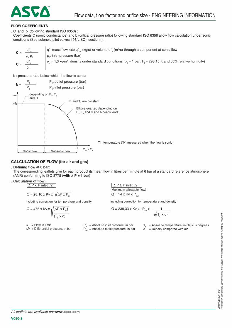
FLOW COEFFICIENTS
. C and b (following standard ISO 6358) : Coefficients C (sonic conductance) and b (critical pressure ratio) following standard ISO 6358 allow flow calculation under sonic
conditions (See solenoid pilot valves 195/LISC - section I).
C =q*m q*: mass flow rate q*m (kg/s) or volume q*v (m
3/s) through a component at sonic flow
ρo p1 p1: inlet pressure (bar)
C =q*v ρ
o = 1,3 kg/m3 : density under standard conditions (p0 = 1 bar, T0 = 293,15 K and 65% relative humidity)
p1
b : pressure ratio below which the flow is sonic:
b =P2 P2: outlet pressure (bar)
P1 P1: inlet pressure (bar)
0 b 1
qm
q*m
CALCULATION OF FLOW (for air and gas). Defining flow at 6 bar: The corresponding leaflets give for each product its mean flow in litres per minute at 6 bar at a standard reference atmosphere
(ANR) conforming to ISO 8778 (with D P = 1 bar)
. Calculation of flow: D P ≥ P inlet /2 (Maximum allowable flow)
Q = 14 x Kv x Pout
including correction for temperature and density
Q = 238,33 x Kv x Pout x 1
D P < P inlet /2 Q = 28,16 x Kv x DP x Pin
including correction for temperature and density
Q = 475 x Kv x (DP x Pin)
(Ta x d)
Pin = Absolute inlet pressure, in bar Pout = Absolute outlet pressure, in bar
(Ta x d)
Ta = Absolute temperature, in Celsius degrees d = Density compared with air
Q = Flow in l/min DP = Differential pressure, in bar
depending on P1, T1 and C
P1 and T1 are constant
Ellipse quarter, depending on P1, T1 and C and b coefficients
T1, temperature (°K) measured when the flow is sonic
Sonic flow Subsonic flowPout / Pin
All leaflets are available on: www.asco.com
V050-8