Embed Size (px)
Citation preview
UNITED STATES DEPARTMENT OF AGRICULTURE NATURAL RESOURCES CONSERVATION SERVICE
WASHINGTON STATE
ENGINEERING INVESTIGATION REPORT WASTE STORAGE POND NEAR SNOHOMISH
SNOHOMISH COUNTY, WASHINGTON July 9, 2010
Project: Bartelheimer Waste Storage Pond Location: Snohomish County, Washington Appropriation: ACP


Page 1 of 21
U.S. DEPARTMENT OF AGRICULTURE NATURAL RESOURCES CONSERVATION SERVICE
Snohomish County, Washington July 9, 2010
ENGINEERING REPORT
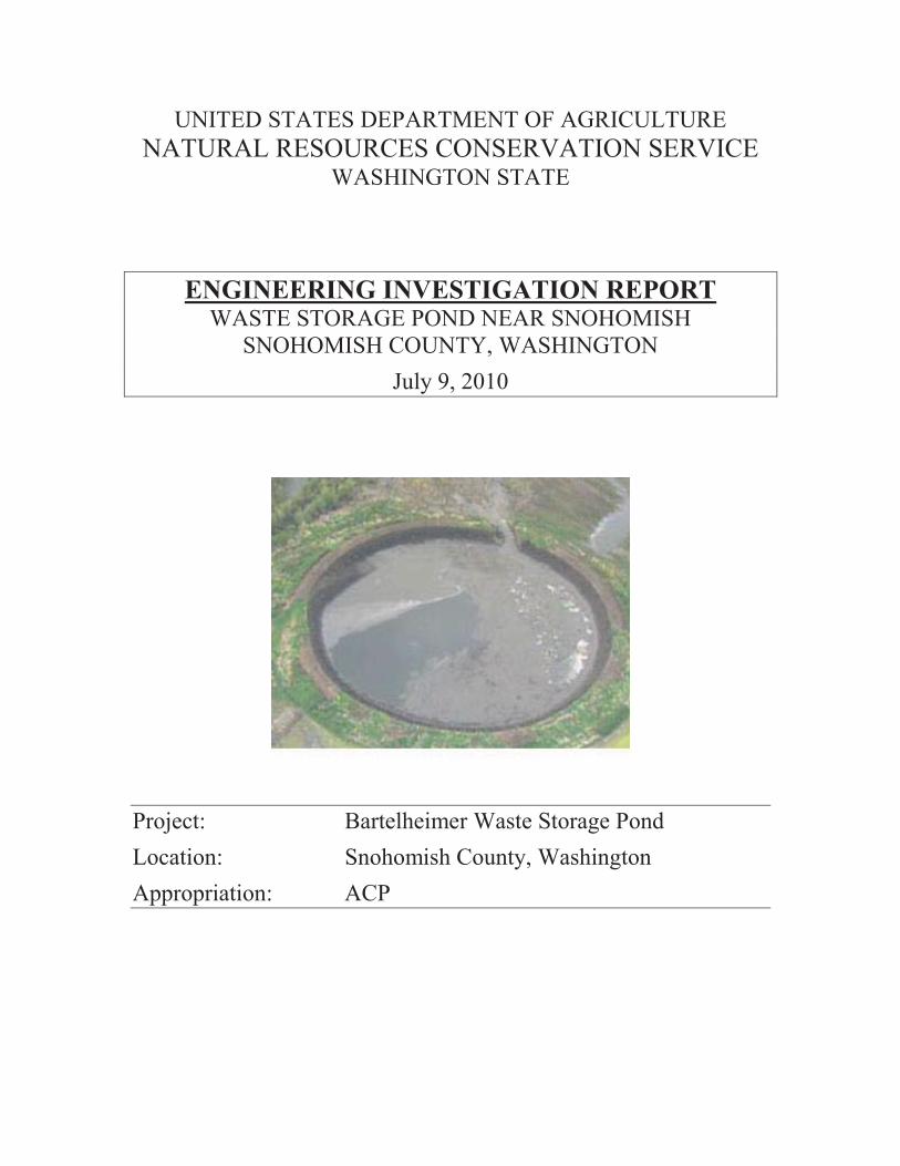
Project: Bartelheimer Waste Storage Pond Location: Snohomish County, Washington Job Class: Class V Appropriation: Agricultural Conservation Program (ACP) DESCRIPTION OF THE PROJECT The Bartelheimer Waste Storage Pond is an impoundment structure for animal waste. The pond is located adjacent to French Creek and the Burlington Northern Railroad, approximately 2 miles east of the City of Snohomish, Washington. Storage is provided by a constructed earthfill embankment, approximately 15 feet high, and excavated dead storage depth of approximately 5 feet. The structure is circular in shape with an approximate diameter of 555 feet. Gross storage capacity is approximately 30.3 million gallons. The waste storage pond was designed by the NRCS in July 1995. Construction was completed in September 1997. GENERAL DESCRIPTION OF THE PROBLEM A complete breach of the waste storage pond embankment has occurred, releasing approximately 27 million gallons of animal waste effluent onto adjacent farmland, some of which entered into French Creek. The embankment breach is approximately 30 to 40 feet wide. Damages include a scour hole of undetermined dimension within the embankment breach area. The waste storage pond is nonfunctional due to significant damage to the embankment and foundation.
AUTHORITY
The investigating committee was appointed by Roylene Rides-At-The-Door, State Conservationist, Washington, by letter dated April 16, 2010, with consultation from Larry Johnson, P.E., State Conservation Engineer, Washington.

Page 2 of 21
COMPOSITION OF INVESTIGATING COMMITTEE Erica Fifer, P.E., Civil Engineer, NRCS, Mt. Vernon, Washington Joe Gasperi, L.P.G., State Geologist, NRCS, Spokane, Washington Kip Yasumiishi, P.E., Civil Engineer, NRCS, WNTSC, Portland, Oregon Ben Doerge, P.E., Geotechnical Engineer, NRCS, NDCSMC, Fort Worth, Texas INVESTIGATION
Scope of Inquiry
The investigation was performed in accordance with Part 504 of the National Engineering Manual. The report format is consistent with guidance provided in Technical Release 24, Investigating Engineering Structural Problems and Deficiencies.
Site Inspection
The investigating committee physically inspected the structure site from April 20 to April 22, 2010. Site inspection included photographic documentation and topographic surveys of the structure including the embankment breach, debris field, and drain tile outlets in the vicinity of the structure, into French Creek. Subsurface investigation consisted of trench excavations on the landside of the embankment breach. Soil samples were obtained for soil mechanics testing.
Additional subsurface investigation was conducted on April 29, 2010. Periodic inspection by individual committee personnel was made from April 27 to April 30, 2010.
Investigating committee notes documenting investigation activities are provided in Appendix G.
Records, Reports, and Documents Reviewed
1. Design Folder
The investigating committee reviewed the design folder including all reports, computations, and other supporting documents. Documents of record are provided in Appendix B.
2. Construction
The investigating committee reviewed and evaluated the construction drawings and construction specifications. Documents of record are provided in Appendix C.

Page 3 of 21
3. Natural Resources Conservation Service and the Snohomish County SWCD Project Files
The investigating committee reviewed the conservation assistance notes relative to planning, design, and construction of the waste storage pond. Documents of record are provided in the appendices.
Key Personnel and Witnesses Interviewed
Joe Lange, Civil Engineer, NRCS, Wenatchee, WA Dean Renner, Stream Mechanics Engineer, NRCS, Olympia, WA Marty Rankin, Civil Engineering Technician, NRCS, Lynden, WA Herb Klug (retired), Civil Engineering Technician, Mt. Vernon, WA Ryan Bartelheimer, former employee, Snohomish County SWCD, Snohomish, WA Jason Bartelheimer, French Slough Partners (Operator/Property Owner), Snohomish, WA Dale Bartelheimer, French Slough Partners (Property Owner), Snohomish, WA Jim Newton, (Neighboring Property Owner), Snohomish, WA SUMMARY OF FACTS
1. Description of occurrence. A complete breach of the waste storage pond earthen embankment occurred sometime between 11:00 AM on April 11 and 11:00 AM on April 12, 2010, based on interviews with the farm operator and neighboring property owner. In addition to the release of the above ground storage volume, approximately 3.3 million gallons of effluent remain as dead storage within the pool of the storage structure and embankment breach. Local and state health and regulatory agencies, as well as Tribes located downstream, were contacted by the landowner when the breach was identified. The state departments of Agriculture, Ecology and Fish and Wildlife, the U.S. Department of Agriculture and other state and local agencies responded to the incident. The embankment breached on the north westerly side of the waste storage pond (opposite to French Creek). The hazard to public health and the environment was mitigated by filtering of the effluent through adjacent farmland prior to reaching surface waters in French Creek. No threat to public drinking water or reports of dead fish were reported by local or state agencies. The Snohomish River just downstream from French Slough met state water quality standards for fecal coliform and dissolved oxygen within six days of the incident, according to Washington State Department of Agriculture (WSDA) testing. In the aftermath of the incident, USDA’s Natural Resources Conservation Service (NRCS) provided technical assistance to the dairy. The agency assessed field vegetation, sampled soils and made recommendations to prevent further run-off of manure from the site.
Page 4 of 21
2. Summary of site conditions and character of materials.
Technical assistance notes from October through December 1994 detail site investigation that was performed at the waste storage pond site. The notes indicate that a drill rig was used to take representative soil samples to determine soil type, moisture content (color), and depth to water table. As-Built construction drawings note five test holes within the foot print of the waste storage pond. Soil logs for the test holes, in general, indicate finer grained soils in the upper 5 to 7 feet of the soil profile underlain by fine to coarse grained sands. Ground water table is not noted on the soil logs in the construction drawings. The original soil logs for the test holes note depth to water table exceeded 10 feet at the time of drilling. Mottling of the soil at depths ranging from 6.5 feet to 8 feet below ground surface indicated seasonal high ground water. Copies of the soil logs are provided in Appendix D. Subsequent investigation by the investigation committee on April 21, 2010, noted fine grained soils (ML) within the upper 7 feet of the soil profile with redoximorphic features to the surface, saturated with free water at a depth of 3.5 feet. The fine-grained surface soils were underlain by saturated sands (SM, SP) from 7 feet to 10 feet in the soil profile. Committee notes detailing the investigation are provided in Appendix G.
3. Summary of key elements and critical features. a. Foundation Investigation. Technical assistance notes detail knowledge of existing buried drain tiles within the vicinity of the waste storage pond during the planning and design of the waste storage pond. In addition, the design report notes the potential for existing drain tiles within the foundation of the waste storage pond and that the exact location of the drain tiles were not known and would not be determined until construction. A chronology of events related to the drain tiles is provided in Appendix E. b. Geotechnical Design. Foundation and embankment design consisted of specification of embankment slopes and soil types to be utilized for embankment fill and the compacted soil liner (Design Report, Appendix B). No other supporting documentation was found.
4. Summary of conditions encountered which differed from those adopted as a
basis of design.
The design report notes that the bottom of the waste storage pond was to be excavated to elevation 7.8 feet (NGVD), the elevation of the seasonal high groundwater table. As-built construction drawings and technical assistance notes of September 24, 1996, indicate that the depth of excavation for the pond bottom was stopped 0.5 feet short of
Page 5 of 21
the design elevation (during construction) due to “soil wetness”, resulting in an elevation of 8.3 feet (NGVD) for the excavated depth of the pond bottom.
The investigation committee noted that the farm operator reported seasonal high ground water table at approximately 12 to 18 inches below ground surface (Appendix F), consistent with the investigation committee’s observations of redoximorphic features in the soil profile during the April 21, 2010, trench excavations.
5. Summary of background experience in the use of similar design under similar conditions. Other embankment and appurtenant structures along the Snohomish River, with similar foundation conditions, had either failed or sustained severe damage due to internal erosion (piping), excessive seepage, or overtopping. Engineering investigations were conducted for the French Creek Pumping Plant (1972, 1980, 1985), Marshland Flood Control Dike (1990), and the French Creek Flood Control Dike (1995) by the NRCS.
6. Summary of critical provisions of the construction specifications.
The construction specifications did not include requirements for removal or decommissioning of existing drain tile if encountered during construction. The investigating committee notes that the design report and the construction drawings (construction note 8, sheet 2/7) both note the potential for drain tiles within the foundation of the waste storage pond and, if encountered, would have to be relocated outside of the pond area.
7. Summary of items in the construction records pertinent to the failure, quality of
inspection, and compliance with specifications.
Construction records note that two change orders were executed during construction of the waste storage pond. Documentation suggests that Change Order No.1, executed on October 2, 1996, authorized the contractor (Horizon Trucking & Excavating Co., Inc.) to remove existing concrete box tile encountered during construction (south east side of waste storage pond) and install a bypass around the structure using plastic ADS drain pipe. Change Order No.2, executed on September 4, 1997, authorized the contractor to install a 10-inch gate valve and appurtenances for the embankment conduit (waste transfer pipeline), and 12-inch diameter ADS drain pipe for drainage of the borrow pit area (located west of the waste storage pond).
Copies of Change Order No.1 and No.2 are provided in Appendix D. Investigation committee notes relative to Change Order No.2 are provided in Appendix G.
8. Summary of actions taken subsequent to failure.
The site was inspected by NRCS staff on April 12, 2010, and by the Washington State Conservation Engineer on April 13, 2010. Investigation committee members

Page 6 of 21
were appointed on April 16, 2010, and initiated its formal investigation on April 20, 2010.
Site inspection from April 20 through April 29, 2010, included detailed surveys of the perimeter of the waste storage pond top and embankment toe, emergency spillway, breach section and debris fan, which included numerous large pieces of earthen embankment, 44 - 2 x 12 wooden planks of various length, and 11 pieces of broken concrete pipe. Surveys included locating the approximate alignment and depth of the wooden box drain tile, uncovered by trench excavations (located downstream from the breach), and drain tile outlets into French Creek. Survey data is provided in Appendix G.
Temporary measures to minimize further discharge of effluent into French Creek have been undertaken by the landowner. NRCS visually monitored discharge from the existing drain tile outlets into French Creek during the course of the investigation for changes in magnitude, color and odor.
Investigation committee notes which document investigation activities are provided in the attached appendices.
9. Summary of standards and criteria that may be inadequate.
Washington State Supplement to the NRCS National Handbook of Conservation Practices (NHCP), Practice Standard 425, Waste Storage Pond, January 1994, provided that waste storage ponds not be excavated below the seasonal high groundwater table. Additionally, the acceptability of natural soil materials for soil liners would be based solely on acceptable material type as classified in accordance with the Unified Soil Classification System. A copy of the Washington State Supplement is provided in Appendix D.
Criteria in the Washington State Supplement have been superseded by more stringent criteria provided in Practice Standard 313, Waste Storage Facility, December 2004. In general, current requirements call for a minimum separation distance of 2 feet from the elevation of the pond bottom and the seasonal high groundwater table. Additionally, the acceptability of natural soil materials for soil liners is now based upon minimum permeability rates or specific discharge as provided in the Agricultural Waste Management Field Handbook, Appendix 10D.
The investigation committee notes that Parts 501 and 503, National Engineering Manual (NEM), provided minimal guidance on hazard potential due to environmental loss from pollution to ground or surface water. Although NEM policy addressed storage capacity and height as controlling factors for job approval, proximity to surface water in the event of failure, is not addressed.
Page 7 of 21
EVALUATION
Possible Causes of the Failure
1. Piping through Embankment
a. Poorly compacted earthfill or permeable zone in embankment b. Animal burrows in embankment c. Shortened seepage path due to erosion on upstream side of embankment d. Seepage path due to tree roots e. Seepage along embankment conduit or other penetration
2. Piping through Foundation
a. Excessive uplift in confined sand layer b. Loss of foundation soil into wooden box tile line c. Shortened flow path due to erosion of compacted soil liner in pond bottom
3. Other
a. Overtopping b. Slope stability failure c. Dynamic loading from Burlington Northern Railroad d. Dynamic loading from seismic events e. Sabotage
Evaluation of Data to Determine Probable Cause
Timing of Failure – The structure operated with no visible or apparent problems for 13 years prior to the failure. However, the final stages of failure progressed rapidly, and the embankment breached in less than 24 hours. Therefore, the failure mechanism would have to have had either a delayed initiation or a very gradual or intermittent progression capable of rapid progression in its final stages.
Operational Considerations – The pond level was at, or near the emergency spillway crest, at the time of failure. According to the landowner, it was not uncommon for the pond to be full by the spring of the year. Therefore, the failure mechanism must be consistent with the fact that there were numerous fillings to maximum head prior to embankment failure. The landowner reported that the pond had not been agitated for a number of years prior to the failure, and that all agitation prior to that had been performed from the ramp, which is located well away from the breach area. The landowner uses sand for bedding which is settled out of the slurry in an intermediate settling pond prior to storage in the waste storage pond that failed. The landowner reported that he does not mechanically remove manure solids from the pond.

Page 8 of 21
Physical Characteristics of Failure – The failure resulted in a breach of the waste storage pond embankment and scouring below natural ground level. Although the areal dimension of the scour hole could not be visually ascertained due to the impoundment of effluent in the void, scour depth of approximately 7 to 8 feet was measured by probing (investigation 4.21.2010). Large amounts of medium-grained, clean sand observed in the debris field, appear identical to the foundation sand observed in the excavated trench (below a depth of about 7 feet). The presence of this sand provides probable evidence that the scour in the breach extends into the sand layer in the foundation. The presence of the cedar boards in the debris field further indicates that the wooden box drain was present in the foundation in the breach area and that the scour in the breach area extended at least down to the elevation of the box drain. The committee noted that some of the cedar boards had sand embedded in the surface, indicating that the box drain was installed in contact with the sand layer. The wooden box drain, in the excavated trench, was observed to be at the interface between the sand layer and the overlying fine-grained soil.
Gradient-Related Considerations – Seepage forces in earth masses are often expressed in terms of hydraulic gradient. The hydraulic gradient between two points in a soil mass is defined as the difference in total hydraulic head between the two points, divided by the flow path length between the points. Sufficiently high gradients can cause piping and other forms of instability to occur in soils. Since failure occurred when the pond was full, it is reasonable to suspect that the failure mechanism was related to the hydraulic gradients that existed within the foundation and/or the embankment at that time. These gradients are directly proportional to the hydraulic head in the reservoir, therefore they would be at their maximum when the pond was full.
In order for piping to occur, the hydraulic gradient at a discharge face must have sufficient magnitude to detach soil particles and transport them away from the discharge face. For normal weight, non-cohesive soils, critical gradient is approximately 1.0. For cohesive soils, critical gradients may exceed 1.0 due to the additional resistance to detachment provided by the chemical attraction between the individual soil particles. The gradient required to produce detachment of particles in cohesive soils cannot be determined except by laboratory testing. However, that gradient will be higher for more cohesive soils, such as clays, and lower for less cohesive soils, such as silts.
Evaluation of Possible Causes of Failure
1. Piping Through Embankment
a. Poorly compacted earthfill or permeable zone in embankment A zone of poorly compacted or highly permeable material in the embankment, if continuous from toe to toe, can provide an avenue for piping through the embankment and possible breaching.

Page 9 of 21
The borrow material for the embankment came from the silt and clay soils in the upper 5 feet (or more) in the pond area, as well as from an adjacent borrow area. The construction specifications required a minimum of 20 percent fines in the fill material. The breach through the embankment revealed that the fill is highly uniform, well compacted, fine grained material that met specification requirements (Photo 31, Appendix A). Other than some very small, discontinuous pockets of silty sand (SM), no coarse grained layers or lenses were observed in the breach area.
The stiff compacted fill is judged to be quite erosion-resistant. Therefore, if the breach had initiated through a permeable zone in the embankment fill, rather than through the foundation, it is considered less probable that the scour in the breach area would have extended down to the sand layer deep in the foundation (7 feet below natural ground surface), as was observed.
If such a permeable zone had existed in the embankment fill, it is probable that it would have initiated failure at an earlier filling, instead of after 13 years of operation.
The investigation committee concludes that it is very unlikely that the failure was caused by a zone of poorly compacted or permeable material in the embankment.
b. Animal burrows in embankment Animal burrows from the downstream side of the embankment can lead to piping by reducing the seepage path length to a critical value. The base width of the embankment is approximately 85 feet and the maximum hydraulic head is approximately 15 feet. Therefore, a rodent burrow would have to extend to within 15 feet of the upstream toe of the embankment for a gradient of 1.0 to develop. This would require 70 feet of tunneling through the very stiff compacted fill.
Numerous rodent holes and mounds were observed on the embankment, including near the breach. The holes had a diameter of approximately 1.5 inches and were observed to be located within six inches of the embankment surface (Photos 32, Appendix A). One small, black rodent about two inches long, presumably a vole, was observed entering one of the holes. No evidence of large, deep rodent burrows was observed on the embankment.
The investigation committee concludes that animal burrows did not play a role in the failure.
Page 10 of 21
c. Shortened seepage path due to erosion on upstream side of embankment Erosion on the upstream side of the embankment, such as that caused by a manure agitator or wave action, could reduce the seepage path length through the embankment such that a critical gradient could develop. As noted in 1.b above (rodent burrows), a very severe amount of erosion would have to occur before a gradient of 1.0 could develop. No such erosion was observed on the embankment face adjacent to the breach. The landowner reported that he had never agitated at the breach site, and there was no evidence of wave induced erosion anywhere in the pond.
The investigation committee concludes that a shortened flow path due to erosion on the upstream side of the embankment did not play a role in the failure.
d. Seepage path due to tree roots If deep rooted trees are allowed to grow on an embankment, the roots can later decompose and leave a preferential seepage path for flow through the embankment and possible breaching by internal erosion.
The embankment was observed to be essentially free of woody vegetation. One small clump of trees was observed at the toe of the embankment about 50 feet to the west of the breach (Photo 33, Appendix A). Numerous blackberry vines are growing on portions of the embankment, but no blackberries were observed near the breach area. No evidence was observed that any trees had grown on the embankment since construction and had died to produce open root channels through the embankment.
The investigation committee concludes that a seepage path due to tree roots did not play a role in the failure.
e. Seepage along embankment conduit or other penetration Seepage can occur through discontinuities and hydraulic fractures in the vicinity of pipes through embankments and other penetrations and lead to breaching. However, there were no pipes or other penetrations at the breach location.
The investigation committee concludes that seepage along pipes or other penetrations played no role in the failure.
2. Piping Through Foundation
a. Excessive uplift in confined sand layer
Page 11 of 21
The foundation conditions at the structure site consist of a low permeability layer of fine-grained soil (silt/clay) overlying a layer of relatively clean sand, as observed in the excavated trenches and indicated in the borings from the original design investigation. This type of foundation is referred to as a blanket-aquifer formation, and uplift pressure can develop under the surface blanket under the influence of a superimposed reservoir. Depending on the unit weight, thickness, and permeability of the blanket , the thickness and permeability of the aquifer, and the head of the reservoir, uplift at the downstream toe can cause piping and/or heave and lead to a breaching failure.
Failure by this mechanism would be expected to occur as soon as steady state conditions developed after construction and operation of the pond. It is considered likely that this would have occurred within the first year or two. Furthermore, signs of failure by this mechanism (such as sand boils, heaving of the blanket, or slumping of the embankment) would be expected to occur over a widespread area and not be confined to an area as localized as the breach.
A seepage analysis using estimated soil parameters was performed to quantify the uplift acting at the downstream toe of the embankment under steady state conditions prior to failure of the embankment. The estimated factor of safety against uplift from this analysis is 1.3, assuming a soil liner thickness of one foot. Results of the uplift analysis are provided in Appendix G.
The investigation committee concludes that uplift due to the blanket-aquifer foundation was not sufficient to cause the failure by itself.
b. Loss of soil material into buried tile line Observations at the breach site, and in the excavated trenches downstream of the breach, provided clear evidence that a wooden box drain passed under the embankment at the breach location. Such a drain line, with openings large enough to permit the entry of soil particles, could provide sufficient open space to permit soil material from the overlying soil in the pond bottom to be removed under the action of the downward hydraulic gradient produced by the head in the reservoir. The net head acting on the soil cover would be equal to the difference between the liquid level in the pond and the ground water elevation outside the embankment. When the pond is full (maximum stage), the net head is equal to approximately 14 feet. Assuming a total soil cover over the box drain of 1.7 feet, the resulting gradient across the soil cover is approximately 8. A gradient of this magnitude is of serious concern and would act on the soil cover at all points along the box drain within the pond area, whenever the pond was full. The gradient would vary annually between approximately zero, when the pond was near empty, and 8 when the pond was full.

Page 12 of 21
The openings in the wooden box drain were observed to be two inches by two inches, and the bottom of the box drain is completely open. Therefore, soil particles could move freely through these openings if they became detached from the adjacent soil mass. It is reasonable to expect that soil particles could be detached and transported into the drain under gradients approaching 8. Because of the cohesiveness of the soil in the cover, the rate of soil particle loss would be expected to be slow. As the pond was emptied, the gradient would fall below that required to detach soil particles, and the loss of soil would cease until the next filling cycle. This cycle of intermittent soil loss into the box drain would eventually cause a vertical tunnel to develop in the soil cover, starting at the bottom of the soil cover and progressing upwards. The rate of tunnel advance would vary depending upon the thickness of the soil cover and the cohesiveness of the soil material. As the tunnel advanced upward, the flow path length would gradually decrease, and so the gradient would gradually increase in a corresponding manner. As the gradient increased, the rate of soil loss would similarly increase.
At the point where the tunnel reached the top of the soil cover, the hydraulic head in the box drain would instantly rise to full reservoir head over the full length of the drain. This would charge the sand layer in the vicinity of the drain to a similar magnitude. The net head acting on the seven-foot thick silt/clay blanket at the downstream toe of the embankment would then be approximately 14 feet. If the saturated unit weight of the silt/clay blanket material is estimated to be approximately 120 lbs./ft3 (pcf), the corresponding buoyant unit weight is 57.6 pcf. The factor of safety against heave is given by:
where,
FS = safety factor against heave using effective stresses
z = thickness of silt/clay blanket, ft
buoyant unit weight of silt/clay blanket, pcf
unit weight of water = 62.4 pcf
net hydraulic head acting on silt/clay blanket
This analysis shows that full reservoir head acting on the silt/clay blanket would greatly exceed that required to cause blow-out of the silt/clay at the downstream toe of the embankment. Once the blow-out occurred, an open conduit would exist between the reservoir and the downstream toe, and the

Page 13 of 21
contents of the reservoir would begin to drain. The instantaneous velocity at the onset of open conduit flow is calculated to be 11 fps (computations provided in Appendix G). A velocity of this magnitude would produce rapid erosion of the highly erodible sands beneath, and surrounding, the box drain. A void would form under the box drain, leading to its collapse under the weight of the overlying embankment. The velocity of the flow would be expected to break apart the collapsed portion of the box drain and push the fragments out towards the downstream side of embankment. The size of the void under the embankment would increase as flow continued until the overlying embankment material would collapse into the void and be sluiced downstream. This process would continue until the pond was drained, leaving a complete breach in the embankment.
The failure mode described above is consistent with the 13 year delay between construction of the pond and the failure, as well as with the rapidity of the final stages of the failure. The failure mode does not rely on other failure mechanisms such as construction defects, erosion from management activities, burrowing animals, tree roots, or earthquakes.
The investigation committee concludes that failure due to loss of soil material from the pond bottom into the wooden box drain is consistent with all site observations as well as with basic soil mechanics principles governing soil response to hydraulic gradients. Failure by the mechanisms described in this section is considered highly probable, and even unavoidable, given the as-constructed configuration of the pond, foundation, compacted soil liner, and box drain tile.
c. Shortened flow path due to erosion or removal of compacted soil liner in pond bottom The sand layer in the foundation of the pond bottom was covered by approximately two feet of fine-grained soil, including the one foot thick compacted soil liner. If the sand had became exposed through erosion or mechanical removal of the soil cover, the permeable sand layer could transmit excessive uplift pressure to the downstream toe of the embankment and result in failure due to piping and/or heave.
The landowner reported that he has never agitated the pond at the breach location, and his management of the pond did not include mechanical removal of solids from the pond bottom. Therefore, there is no evidence that erosion or mechanical removal of the soil cover over the foundation sand layer has occurred at the breach location.
The investigation committee concludes that it is unlikely that erosion or removal of the cover soil over the foundation sand layer was causative of the failure.

Page 14 of 21
3. Other
a. Overtopping If the level of the liquid in the pond exceeds the low point on the top of the embankment, the resulting overtopping flow can erode the embankment fill and lead to a breach of the embankment.
Observation of the emergency spillway crest showed no appreciable flow of effluent had passed through it recently. It is considered improbable that the top of the embankment, at the breach site, was sufficiently lower than the emergency spillway to permit overtopping at that location without flow passing through the emergency spillway. The as-built elevation of the spillway crest (28.0 feet) is 1.3 feet below the as-built elevation of the embankment (29.3 feet). The manure line around the inside crest of the embankment is at or very close to the emergency spillway crest elevation.
Little or no rain occurred at the structure site immediately prior to the failure. Therefore, the only inflow into to the pond could have been from effluent from the dairy operation. This flow rate, even if left to flow into the full pond and overtop the dam, is considered insufficient to cause appreciable erosion to the embankment fill and a complete breach of the embankment in less than 24 hours. The embankment consists of well compacted, erosion-resistant silt/clay material, and the landside slope is protected by a dense stand of grass at the breach location.
The investigation committee concludes that overtopping was not a factor in the failure.
b. Slope stability failure Embankments can breach if slope failure of either the downstream (landside) or upstream slope results in the top of the embankment crest dropping below the liquid level in the reservoir.
The failure occurred when the reservoir was at maximum stage, which represents the maximum static loading for the downstream slope, but the minimum static loading for the upstream slope. It is difficult to develop a working explanation of circumstances that would lead to slope failure after 13 years of structure use and not at a previous time when the pond was equally full. Slope failure would also have been expected to have occurred in a more widespread manner, since the embankment and foundation conditions are quite uniform throughout the entire embankment. Slopes outside of the breach area show no visible signs of instability. The upstream slope (2H:1V) is likely more critical under rapid drawdown conditions than the downstream slope (3H:1V) under steady seepage conditions.

Page 15 of 21
Embankment fill, exposed in the breach, appears to be uniform and well compacted. The fill is very stiff, based on thumb penetration and pocket penetrometer tests. Professional engineering judgment suggests that the fill should have sufficient shear strength to sustain a downstream slope of 3H:1V with adequate stability. Samples were collected to check the degree of compaction of the fill and to determine its shear strength and other parameters required to perform a slope stability analysis for the embankment.
The investigation committee concludes that it is unlikely that slope stability failure played a role in the failure. Slope stability analysis utilizing soil mechanics test results and approximate material property values confirms this conclusion. Results of the analysis can be found in Appendix G.
c. Dynamic loading from Burlington Northern Railroad The investigation committee witnessed a number of trains passing by the site during investigation of the waste storage pond. Ground vibration could not be felt and the committee did not observe any vibration in the standing pools of water at the site.
The investigation committee concludes that vibrations from the nearby railroad played no role in the failure.
d. Earthquake-related effects USGS records of measured earthquakes in Western Washington for the three days prior to the failure indicate that the strongest earthquake was Magnitude 1.8. An earthquake of this very low magnitude would produce no detrimental effects at the structure site.
The investigation committee concludes that earthquake-related effects played no role in the failure.
e. Sabotage While heavy equipment was seen operating on the landowner’s property during the day before the failure, it was determined that it was just the landowner performing routine farm operations.
The investigation committee concludes that there is no basis for suspecting that sabotage played any role in the failure.
Page 16 of 21
Collection and Interpretation of Basic Data
The existence of drain tiles in the vicinity of the waste storage pond site was documented in the technical assistance notes during planning and design of the structure. Information relative to the discovery of three drain tile outlets into French Creek, the bypass of a wooden box drain by the landowner because of a sinkhole, and a 1947 (sic) aerial photo showing open trenches along the box drain alignment is documented in the notes from May 1995 (included in Appendix G). The aerial photo clearly shows that the suspected sinkhole was located within the future pool area of the waste storage pond and that the box drain passes under alignment of the future embankment, in fact, at the precise location of the 2010 breach. This information was available in the project file prior to completion of the final design.
Removal of existing drain tiles from the structure footprint was addressed during design (noted in the design report) and two such drain tiles are identified on the construction drawings for removal and relocation (Construction Note 8, Sheet 2/7, Construction Drawings, Appendix C) . It is therefore unclear why the wooden box drain, whose existence was known and reported, was not included, especially since the design report states that as many as three tile lines may be present within the pond area. The designer was unable to explain this omission to the committee because he reported that with the passage of the intervening 15 years and without the benefit of the case file to refresh his memory, he was unable to recall any of the details of his May 15-23, 1995, discussions with the landowners regarding the existing tile lines.
Geotechnical Exploration
The geotechnical exploration of foundation conditions was incomplete. The investigative committee found five drill logs in the project file. However, the drill logs were unsigned, so it remains unclear whether or not the person who logged the drill holes had the appropriate training to recognize potential hazards associated with this site. The investigative committee did not find any laboratory data to confirm the field classification of the soil or to obtain data required for an uplift analysis. The committee also did not find any geology report or geotechnical report.
More importantly, the drill logs significantly misinterpret the depth of the seasonal high water table. A seasonal high water table is noted on one of the drill logs at a depth of nearly eight feet below ground surface, whereas discussions with Jason Bartelheimer by the investigative committee and redoximorphic features observed in the excavated pits indicate a seasonal high water table of 12 to 18 inches below the ground surface.
Because of this misinterpretation, there was only a 6 to 12 inch separation distance between the wooden box drain buried in the foundation and the underside of the animal waste storage pond. If the depth to the seasonal high water table had been more accurately recognized, and the waste storage pond constructed in accordance with the provisions in the then current practice standard, the separation distance between the wooden box drain and the underside of the animal waste storage pond would have been
Page 17 of 21
as much as 7 or 8 feet. Such a buffer may have protected the structure from this mode of failure for the remainder of its design life.
Failure to conduct a geotechnical exploration by qualified personnel contributed to the failure of this structure.
Design The design folder contains no geotechnical analyses such as for uplift in the blanket-aquifer foundation, slope stability, or settlement. The proposed removal of most of the blanket in the pool area represented a serious increase in the potential for uplift problems and should have been evaluated, especially in light of the previous failures with other embankment structures along the Snohomish River. It should be noted that the lack of an uplift analysis did not contribute to the failure of the structure. The existence of a suspected sinkhole caused by the wooden box drain within the future pool area, and visible on the 1948 aerial photograph, represented a very serious threat to the safety of the proposed structure because it meant that a high probability failure mode was built into the foundation of the embankment. The seriousness of this threat was greatly increased by the fact that most of the silt/clay blanket in the pool area was to be removed for borrow during construction. This removal would greatly increase the hydraulic gradient through the soil cover over the box drain and, correspondingly, the potential for the soil cover to be piped into the drain. In the professional opinion of the investigating committee, the design engineer should have recognized the extreme seriousness of the threat posed by the box drain and included in the design all measures required to insure its removal. The approximate alignment of the box drain was known from the 1940’s aerial photo, and the drain should have been included on the construction drawings for removal.
In the designer’s response to the draft engineering report (included in Appendix I), he states that the landowner was assigned all responsibility for identifying and removing all existing tile lines within the footprint of the structure by means of the “Location of Utilities” statement (Sheet 1, Construction Drawings) and Construction Note 8 (Sheet 2, Construction Drawings) which requires removal of all existing tile lines “at least 25 feet outside the proposed pond area.” He also states that “the Landowner took an acceptable risk, on their own behalf, by making the decision to not remove the tile line,” presumably referring to the wooden box drain.
The investigation committee does not agree that the suggested assignment of all responsibility to the landowner absolves the designer of any and all responsibility regarding the removal of existing tile lines. The following reasons are given:
Typically, the purpose of the utility statement in NRCS work is to prevent damage to utilities and to insure the safety of those present during construction. In this case, however, the fundamental concern was to remove buried features which posed a serious threat to the safety of the structure itself.
Page 18 of 21
According to NRCS policy, the primary responsibility of any employee engaged in professional engineering practice is to safeguard life and property (see General Manual, Title 210, Engineering, Part 402, Professional Engineering Practice), therefore, the designer should not delegate the completion of features critical to the safety of the design to others without at least verifying that these features had been satisfactorily completed.
The designer is the most knowledgeable and responsible party regarding the safety of the structure under consideration and should not allow a potentially less knowledgeable party to make final decisions which could adversely affect the safety of the structure. Such an action would constitute a breach of the designer’s primary duty to safeguard life and property.
Acceptable methods were used by the designer to determine hydrology and hydraulic requirements for the waste storage structure.
Construction
Conservation technical assistance notes and interviews with NRCS personnel indicate that construction operations followed standard industry practice for the time period. Construction started in September 1996 and was completed in September 1997. Inspection was not continuous and the designer’s involvement during construction was primarily limited to resolution of problems associated with compaction requirements of the embankment fill.
It is estimated that the excavation of the pond bottom came within 0.7 ft from the top of the wooden box drain tile after NRCS directed that the pond bottom be raised 0.5 feet due to high water content in the foundations soils during construction. Approximate elevation of the wooden box drain tile relative to the waste storage pond soil liner is detailed in Appendix D.
Since the construction drawings only showed two drain tiles to be removed and relocated, the investigation committee does not consider it reasonable to have expected the construction contractor to have gone “prospecting” for any additional tile lines unless specific direction to do so had been included in the drawings and/or specifications. Therefore, it is the investigation committee’s opinion that the construction contractor shares no responsibility for the failure to remove the wooden box drain.
The lack of adequate quality assurance on the part of the designer was ultimately responsible for allowing the wooden box drain to remain in place and eventually cause the failure of the structure. The designer should have verified that the box drain had been removed before final-approving the construction.
OPERATION AND MAINTENANCE
An Operation and Maintenance Plan (Appendix B) for the structure was included in the design documentation and provided general recommendations to maintain satisfactory performance of the pond. The recommendations in the O&M plan included, but not

Page 19 of 21
limited to: maintenance to control vegetation, control of erosion due to wave action or scour from an agitator directed towards the pond bottom or sides, and emptying the pond to provide storage capacity for the accumulation of animal wastes and precipitation during the storage period.
The landowner reported that no repairs to the pond embankment have been made and that the only maintenance performed was mowing to control vegetation. No evidence of erosion on the embankment face adjacent to the breach was noted and the landowner reported that no agitation or removal of solids in the vicinity of the breach had been performed. Therefore, neither of these operations contributed to the failure.
The manure line on the inside slope of the pond indicates that the pond had been filled one or more times to the crest of the emergency spillway (Elev. 28.0, from as-built drawings). The original drawings show a maximum normal pool elevation of 25.5 feet. Since the top of dam and emergency spillway crest were raised 0.3 feet during construction, it is assumed that the maximum normal pool elevation could also be raised 0.3 feet to 25.8 feet. Therefore, the pool had been filled one or more times to an elevation 2.2 feet higher than that specified by the designer (28.0 feet – 25.8 feet = 2.2 feet).
When the pond is filled to the emergency spillway crest (Elev. 28.0), the hydraulic gradient through the soil liner above the wooden box drain = (14 feet)/(1.7 feet) = 8 ft/ft. If the pond is only filled to the maximum normal pool elevation of 25.8 ft, the hydraulic gradient is reduced to (14 – 2.2 feet)/(1.7 feet) = 7 ft/ft. If the pond had only been filled to 25.8 feet, the potential for piping of the soil liner into the box drain would still have existed, just at a slightly slower rate. The difference between a gradient of 8 ft/ft and 7 ft/ft is considered insignificant. Therefore, it cannot be stated with any certainty that filling the pond only to the maximum normal pool instead of to the emergency spillway crest would have prevented the eventual failure. On the other hand, it can be stated with certainty that filling the pond all the way to the emergency spillway crest would not have caused a failure if the wooden box drain had been removed. The proof of this statement lies in the fact that the pond never failed by uplift during the times when it was filled to the emergency spillway crest, until the soil liner had been compromised by being piped into the box drain. Finally, calculations similar to those given on page 12 of this report show that blowout would still have occurred at the downstream embankment toe following the breach of the soil liner, even if the pond level had only been at 25.8 feet
CONCLUSIONS
The investigating committee concludes that piping of the waste storage pond’s compacted soil liner into the wooden box drain led to an eventual breaching of the liner. The resulting hydraulic connection between the wooden box drain and the liquid in the waste storage pond (at maximum stage) caused the critical head beneath the confining silt-clay layer to be exceeded, causing a blowout of the silt-clay layer near the downstream embankment toe. This was followed by an uncontrolled release of the contents of the waste storage pond and an eventual breach of the embankment.

Page 20 of 21
The investigating committee notes that knowledge of the drain tiles in the vicinity of the waste storage pond was discussed during the planning and design phases of the project. Field location of the drains tiles should have been conducted prior to construction given the potential hazard to embankment stability from the drain tiles being left in place. Furthermore, the wooden box drain tiles’ satisfactory removal/relocation should have been confirmed prior to giving final approval to the construction. Responsibility for the failure of the waste structure is assigned to planning and design.
RECOMMENDATIONS
The investigating committee provides the following recommendations for consideration:
1. The decision on whether or not to repair the structure and return it to service should be based on considerations including acceptable risk, landowner preferences, and regulatory requirements.
2. If the structure is to be repaired, the following actions are recommended:
a. The wooden box drain, which extends through the embankment breach, should be removed from the footprint of the structure, or decommissioned in such a manner to render the box drain tile harmless to the integrity of the structure.
b. Investigation to verify the location and depth of all drain tiles within the vicinity of the waste storage pond should be performed.
c. Additional geologic investigations should be performed to obtain the input data required to perform slope stability and blanket-aquifer uplift analyses around the entire perimeter of the embankment. It is suggested that a hollow-stem auger drill rig, capable of mud-rotary drilling to a depth of 50 feet (minimum), be used to collect undisturbed soil samples and conduct standard penetration testing.
d. The design should address all relevant geotechnical considerations including seepage, settlement, slope stability, and seismic effects. It is suggested that the remedial design be reviewed by a qualified geotechnical engineer.
3. Washington State NRCS develop specific guidance on risk assessment associated
with the hazard potential due to environmental degradation from pollution to ground or surface water from waste storage ponds. It is recommended that in addition to storage capacity and height of embankment, proximity to receiving bodies of water be considered.