Embed Size (px)
Citation preview
AD-A208 594 CR 89.010April1989
N O E L An Investigation Conducted by
Engineering Management Concepts
Contrct R portSponsored by
Contract Report Naval Facilities Engineering Command
EVALUATION OFPLASTIC MEDIA
BLASTING EQUIPMENTDTIC
Sf ELECTE
JUN0 6 1989
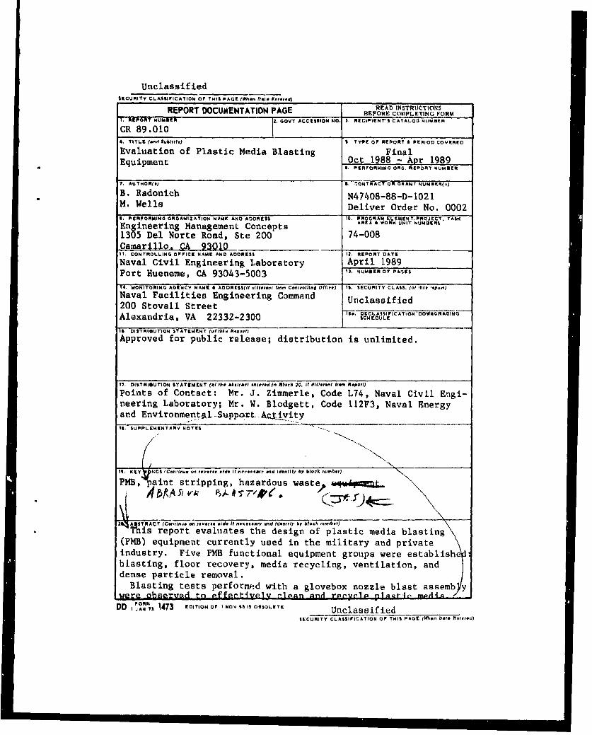
'-HABSTRACT This report evaluates the design of plastic neietia blasting(PMB) equipment currently used in the military and private industry. FivePMB functional equipment groups were established: blasting, floor recov-ery, media recycling, ventilation, and dense particle removal.
Blasting tests performed with a glove box nozzle blast assembly wereobserved to effectively clean and recycle plastic media. Magnetic contami-nants in the system were removed at the rate of 40 percent per pass. Thecoating removal rate was determined to be directly proportional to themedia flow rate and the sine of the blasting angle of incidence.
89 605 16tNAVAL CIVIL ENGINEERING LABORATORY qORT HUENEME CALIFORNIA 93043
REPRODUCED FROM "BEST AVAILABLE COPY Approved for public release; dilbution is unlimited.
y -0
> E >U
x -C
2n en 4. 42r-C C. C-U
Z 0 o- C52Z -- -W 0
c~cc
C ~CL
"L).- q q
Ec- EEEE E~ E0.03 EE EE
CA~ IWC~)~~::C3 .3.3 LZ (1 6 L L 't Et Z 6 8z L
I-I'l. rp.
CAC
.0 Z
.20 3. .C0. C C
w3 0
>- cc . 5 ELn *CN c-n
UnclassifiedSECURITY CLASSIFICATION OF THIS PAGE (When 041. F.nre,.d)
REPORT DOCUMENTATION PAGE READ INSTRUCTIONSREPORT________________PAGE_ BEFORE COMPLETING FORM
I. REPORT NUMOCR -2. QOVY ACCESSION NO. S. RECIPIENT'S CArTALOO NUMER
CR 89.0104. TITLL fnd Souilltle) S TYPE OF REPORT A PERIOD COVEREDO
Evaluation of Plastic Media Blasting FinalEquipment Oct 1988 - Apr 1989
I. PERFORMING ORG. REPORT NUMUER
7. AUTHOR($) ". ,'ONTRACT OR GRANT NUMBER(.)
B. Radonich N47408-88-D-1021M. Wells Deliver Order No. 0002I. PERFORMING ORGANIZATION NAME AND ADDRESS 1. PROGRAM ELEMENT, PROJECT, TASK
Engineering Management Concepts AR4A- Is00 UN8 T •I,-ERS
1305 Del Norte Road, Ste 200 74-008Camarillo. CA 9301011. CONTROLLING OFFICE NAME AND ADDRESS 12. REPORT DATE
Naval Civil Engineering Laboratory April 1989Port Hueneme, CA 93043-5003 13, NUMBER Of' PAGES
14 MONITORING AGENCY NAMAE A AODR[SS(fif difir,.ars Ito, Conirv.IInI OffI•ce) 15. SECURITY CLASS. (01 fhi* report)
Naval Facilities Engineering Command Unclassified200 Stovall Street ____T__
Alexandria, VA 22332-2300 SCHEDULE C
1iS DISTRIBUTION STATEMENT (Pu th. ReportI
Approved for public release; distribution is unlimited.
17. DISTRIOUTION 'AT'EMtNT (o' IPh* abtract #mite'd In Block 20;. I dit(IrenI rom Repo,()
Points of Contact: Mr. J. Zimmerle, Code L74, Naval Civil Engi-neering Laboratory; Mr. W. Blodgett, Code 112F3, Naval Energyand Environmentsl..Support AcryvityIS. SUPPLEMENTARY NOTES
IE Yý "D 3 (Continue on reverse slde it necessaryI and Identity1 by block number) '
aint stripping, hazardous wasted o
I •AUSTRACT (Cot'linue a, eteoln ride IIf mo.iouar and Ientrillf by leob .n.mber)This report evaluates the design of plastic media blasting
(PMB) equipment currently used in the military and privateindustry. Five PMB functional equipment groups were establishe iblasting, floor recovery, media recycling, ventilation, anddense particle removal.
Blasting tests performed with a glovebox nozzle blast assemb ywere observed to Affctively j-A- n and rPi'valp plggat-jr, jrnStf
4 nS_
DD Io, 1473 EDITION OF I NOV AS IS OSSO1,trE UnclassifiedSECURITY CLASSIFICATION OF THIS PAGE (when Data Entered)
Unclassified51CUmITV CLAIIFICATION OF THIS PAGIQUPh. Dole Inlr*,d)
Magnetic contaminants in the system were removed at the rateof 40 percent per pass. The coating removal rate was determinedto be directly proportional to the media flow rate and the sineof the blasting angle of incidence.
UnclassifiedSECu 'iTY C.ASSIrlCAIION Of TWS PAC 'Whn 0-c. FAI-40d)
FOREWORD
This work was sponsored by the Naval Facilities EngineeringCommand and the Naval Civil Engineering Laboratory as part of theprogram to minimize hazardous waste generation from paint strippingoperations in the Navy. Typical paint stripping operations generatelarge quantities of hazardous sludges and wastewaters. PlasticMedia Blasting (PMB) is an emerging alternative to chemicalstripping which greatly reduces the amount of hazardous wasteproduced. This work is a basic technical evaluation of PMB blastingequipment emphasizing required design parameters for efficientequipment operation.
The results of this study are intended to be used t'e improve thegeneral performance of future PMB equipment procured by the Navy.The use of alternatives such as PMB will help the Navy reach a1992 goal of reducing hazardous waste generation by 50%.
If you are planning to implement or have a need for this technologyplease contact:
Mr. J. ZimmerleCode L74Naval Civil Engineering LaboratoryPort Hueneme, CA 93043-5003(805) 982-5085
A/V 360-5085
Mr. Wayne BlodgettCode 112F3Naval Energy and Environmental
Support ActivityPort Hueneme, CA 93043(805) 982-3351
A/V 360-3351
Accession For
ItiH'EI~ONTIS GRA&IDTIC TAB 0Unannounced C1Justlflumion
By-Distribution/
Availability Codesiia'*-i and/or
Dist Special
V
EVALUATION OF PLASTIC MEDIA BlASTING EQUIPMENT
SUMMARY OF RECOMMENDATIONS
Plastic media blasting (PMB) Is a new technology Introduced as a candidate to replace wet chemicalpaint stripping of airframes and component parts. This report evaluates the performance of blastingequipment currently in use and presents minimum design requirements for PMB equipment. Theperformance evaluation includes equipment design, ease of operation, maintenance and operatingparameters such as pressure and feed rate accuracy, nozzle selection, and feed cone anale. A goodtraining program for blasting equipment operators is required to ensure that the equlpment is usedcorrectly to obtain maximum performance.
Plastic media blasting equipment for a blasting room should include the following features to obtainthe best system options currently available. Features unique to a glovobox or blast room have beennoted.
1. Blasting Equipment
A. Blasting pots should be furnished with a 60 degree slope on the bottom conical section,
B. Each nozzle should have a separate blast pot with a minimum storage volume of 3 cubic feet.The storage hopper should have a minimum volume of 6 cubic feet.
C. The storage hopper should be furnished with a level Indicator. An optional level Indicator li theblasting pot may also be furnished.
D. The design pressure of the blast pot should not be less than 110 pounds per square Inch gagepressure. The pressure vessel should be constructed in accordance with Section VIII ofthe ASME Boiler and Pressure Vessel Code.
E. The media refill valve should not leak when the pot Is pressurized and should have at least oneelastomeric surface to produce a tight seal.
F. The storage hopper and blast pot combination should operate automatically to fill the blast potwhen the blast hose Is not in operation. The blasting pot access should be covered with alarge mesh screen to prevent entry of foreign material.
G. For critical applications, a mechanical media feeder should be used to ensure accurate andreproducible media feed rates. Mechanical speeds must be strictly controlled. Feed ratesshould be variable from 10 to 100 percent of maximum media flow. A feed rate Indicatolshould be furnished.
H. The media feed mechanism should be able to feed up to 20 pounds of media per minute with a0.5 Inch bore nozzle.
I. Gravity media feed systems provided for non-critical media flow blasting operations should befurnished with an adjustable valve marked to show Its position. The difference betweenthe pot pressure and the air line pressure should also be Indicated if this method Is usedto help deliver media to the transport hose.
vil
J. Media feed rate and blasting hose air pressure should be easily adjusted by the operator,Controls for adjusting the blasting air pressure and the media flow rate should be easilyaccessible to the operator if rapid transitions between different substrates are required.
K. Abrasion resistant blasting hoses should be light weight and electrically groan. , Hoseweight should not exceed 0.7 pounds per foot.
L. Easily replaceable, venturl style nozzles should be employed. Nozzle size and numberdepends on the application.
M. The hose should be fitted with an Occupational Safety and Health Administration (OSHA)approved deadman switch.
N. The hose should be fitted with a twist swivel if the blasting nozzle assembly orientationcannot rotate freely during operation.
2. Floor Recovery Equipment
A. The solid portions of the concrete blasting room floors should be covered with epoxy, rubbersheeting, or similar material to prevent hard particle contamination of the media fromeroded floor material.
B& Media recovery pits In blasting rooms should have a minimum capacity of about 6 cubic feet.They should not be located near ventilation system exhaust ducts to minimize medialosses to the ventilation system,
C. The slope of media recovery collection troughs or pit bottoms should be a minimum of 60degrees.
D. Fall through style floor recovery equipment should be covered with close patterned steelgrating strong enough to structurally support anticipated loads. The grating may becovered with wire mesh to minimize large foreign object entry into the recycling system.
E. Blasting debris transport rates should be at least twice the maximum flow of rate of medlafrom blasting nozzles to allow for sufficient storage hopper refill time.
F. Recovery and transport systems should not destroy reusable media w, ien In operation.There should be adequate clearance between the walls of the screw conveyor tube andconveyor Internals.
G. Pneumatic media transport rates should be between 25 and 75 feet per second.
H. Mechanical recovery systems should be able to operate In a dusty, abrasive environment.Lubricated, close tolerance equipment should be isolated from the blasting debris.
I. Partial floor recovery areas should be located away from the walls of the blast room to maximize
collection efficiency.
J. Horizontal surfaces under floor grating should be minimized to avoid a build-up of media.
K. The media recovery system in the bottom of the glovebox should transport all blasting debrisfrom the blasting chamber.
L. The working floor of a glovebox should be perforated to allow blasting debris to fall through Itwhile still screening out large foreign objects.
viii
M. The working floor of a glovebox should be fitted with a turntable for work piece accessibility.
3. Media Recycling Equipment
A. High efficiency recycling equipment should be used to remove potentially damagingcontamination from the recycled media, and should not reject properly sized media fromthe recycling equipment. The dust collected by the dust collection system should containless than 5 percent by weight plastic media retained on a 60 mesh screen. The reusablemedia should contain less than 5 percent material passing through a 60 mesh screen.
B. The recycling system should first effect a separation using an adequately sized cyclone toremove fine particles from the material stream. An adjustable air wash or air knifearrangement should be used for final dust and fines removal. The size of the particles thatthe air wash rejects should be manually adjustable based on the blasting operation.
C. After fine particle removal, the media should be classified by size. A two-tier vibratingscreen system should be used for size classification. If an air wash Is used, however, avibrating screen may not be necessary. A stationary 12 mesh screen is still required toprevent damage caused by oversized particles or debris. The screen should be cleanedautomatically in a blast room. Manual cleaning Is appropriate for a glovebox,
D. An adequately sized magnetic separator should be used to remove ferrous debris.Commercially available, self cleaning magnetic separators are removing 30 to 40 percentof the magnetic particle contamination by weight per pass of the media through thesystem, and should be specified whenever possible.
E. The discarded material collection system should deposit collected dust in a storage bnti orhopper that can be emptied with a minimum exposure of personnel to the material,
F, All access doors should be equipped with rubber gaskets. Access doors should be fittedwith Interlocks to prevent operation of the blasting equipment when the doors are open.
G. Electrical equipment located outside of the blasting enclosure should be housed In Class II,Division II, NEMA Type 9 enclosures, unless the operating area requires a more stringentelectrical classification.
H. Use of thln-walled, wire reinforced, flexible ducts for carrying dust laden air streams shouldbe avoided.
Media transportation within the recycling system should be accomplished either mechanic-ally or pneumatically. Mechanical transportation such as bucket elevators, however, mayreduce energy consumption and minimize media damage.
4. Ventilation Equipment
A. The dust collection system (DCS) should be a reverse pulse unit with cartridge style filterelements. The air-to-cloth ratio should not exceed 3.0.
B. The operation of the DCS reverse pulse mechanism should be automatic. The mechanismshould be activated by the differential pressure across the filter element or by a timer witha differential pressure switch override. The timer and the differential pressure switchsettings should be adjustable.
ix
C. Blasting booths should have gravity separation chambers In the ventilation system exhaustducts that automatically return captured reusable media to the media recycling system,
D. The average velocity In the ventilation ducts should be about 3000 feet per minute (fpm) tominimize eroslon damage and prevent accumulations of dust within the ductwork.
E. The DCS should deposit collected dust In a storage bin or hopper that can be emptied witha minimum exposure of personnel to the dust. The dust hopper should be furnished witha level indicator to Indicate when it is full.
F. Adequate access hatches should be provided on the DCS to easily replace cartridge filterelements and provide normal maintenance,
G. Platforms should be provided for all elevated access hatches on the DCS.
H. The induced draft fan should be located on the clean side of the DCS.
5. Dense Particle Removal Equipment
A. Good housekeeping and proper enclosure design should be used to help reduce denseparticle contamination.
B. The Air Force recommends that dense particle contamination In recycled media should be nogreater than 200 ppm. Dense particle removal equipment suitable for use in a productionenvironment, that can provide media 99.98 percent clean, should be developed,
C. Dense particle separators should be of the type that will avoid the use of environmentallysensitive chemicals such as freon as the separation liquid.
D. If a wet-wash system Is specified it Is essential that the media Is thoroughly dried before it isreturned to the blasting operation,
E. Many effective separation techniques that may be applicable to PMB have been perfected bythe mining Industry. One of these techniques, tabling, appears to be a good candidate toclean plastic media and should be Investigated. Fluidized bed techniques that can cleanmedia on a continuously operating as well as a batch basis should also be developed.
x
TABLE OF CONTENTS
SECTION PAGE
1.0 INTROrNUCTION 1
1.1 Objectives 11.2 Background 1
2.0 PMB EQUIPMENT CLASSIFICATION AND DESCRIPTION 2
3.0 BLASTING EQUIPMENT 43.1 Blast Pot and Storage Hopper 43.2 Media Metering System 63.3 Media Delivery System 83.4 Wheel Blasting Systems 8
4.0 FLOOR RECOVERY EQUIPMENT 104.1 Description of Full and Partial Floor Recovery Equipment 104.2 Mechanical Floor Recovery Systems 114.3 Pneumatic Floor Recovery Systems 16
5.0 MEDIA RECYCLING EQUIPMENT 235.1 Cyclone Separators and Rotary Valves 235.2 Vibrating Screens 245.3 Magnetic Separator 245.4 MIscellaneous Equipment 25
6.0 VENTILATION EQUIPMENT 266.1 General Description of Ventilation Systems 26
7.0 DENSE PARTICLE REMOVAL EQUIPMENT 297.1 General Description of Dense Particle Removal Equipment 29
8.0 PLASTIC MEDIA BLASTING GLOVEBOX 318.1 Blasting Equipment 318.2 Floor Recovery Equipment 318.3 Media Recycling Equipment 318.4 Ventilation Equipment 31
9.0 EQUIPMENT TEST DATA 339.1 Glovebox Blasting Tests 33
9.1.1 Media Flow Rate Test 33
9.1.2 Magnetic Separator Test 339.2 Nozzle Blasting Tests 349.3 Wheel Blasting Tests 38
xi
LIST OF TABLES
TABLE PAGE
1 Shot Removed by Electromagnet 342 Nozzle Blasting Tests 37
LIST OF FIGURES
FIGURE PAGE
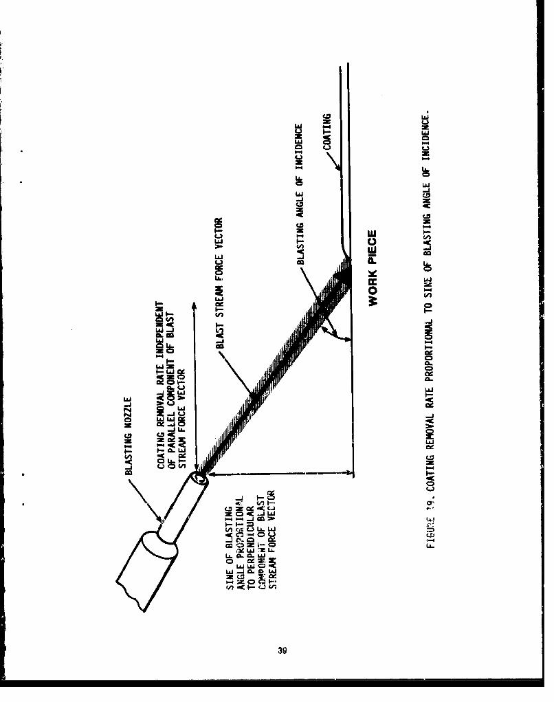
1 PMB Equipment Schematic 32 Blasting Equipment Nomenclature 53 Mechanical Media Feed System 74 Pneumatic Dustpan 125 Media Recovery Pit 136 Typical Partial Floor Recovery Layout to Minimize Sweeping Distances 147 Portable Collection Shield and Cyclone 158 Traveling Sweeper Arms Floor Recovery System 179 Conveyor 3elt Floor Recovery System 1810 Screw Conveyor Floor Recovery System 1911 Reciprocating Shaker Pan Floor Recovery System 2012 Pneumatic Floor Recovery System 2113 Traveling Vacuum Head Floor Recovery System 2214 Ventilation System Nomenclature 2715 Glovebox Nomenclature 3216 Weight of Shot Removed 3517 Log Weight of Shot Removed 3618 Panel Sections For Nozzle Blasting Tests 3719 Coating Removal Rate Proportional to Sine of Blasting Angle of Incidence 39
LIST OF APPENDICES
A WHEEL BLASTING TESTS A-1
xit
1.0 INTRODUCTION
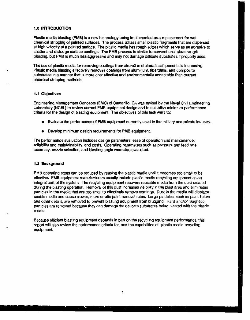
Plastic media blasting (PMB) is a new technology being implemented as a replacement for wetchemical stripping of painted surfaces. The process utilizes small plastic fragments that are dispersedat high velocity at a painted surface. The plastic media has rough edges which serve as an abrasive toshatter and dislodge surface coatings. The PMB process is similar to conventional abrasive gritblasting, but PMB is much less aggressive and may not damage delicate substrates if properly used.
The use of plastic media for removing coatings from aircraft and aircraft components is increasing.Plastic media blasting effectively removes coatings from aluminum, fiberglass, and compositesubstrates in a manner that Is more cost effective and environmentally acceptable than currentchemical stripping methods.
1.1 Objectives
Engineering Management Concepts (EMC) of Camarillo, CA was tasked by the Naval Civil EngineeringLaboratory (NCEL) to review current PMB equipment design and to eStablish minimum performancecriteria for the design of blasting equipment. The objectives of this task were to:
"* Evaluate the performance of PMB equipment currently used in the military and private industry.
"* Develop minimum design requirements for PMB equipment.
The performance evaluation Includes design parameters, ease of operation and maintenance,reliability and maintainability, and costs. Operating parameters such as pressure and feed rateaccuracy, nozzle selection, and blasting angle were also evaluated.
1.2 Background
PMB operating costs can be reduced by reusing the plastic media until it becomes too small to beeffective. PMB equipment manufacturers usually include plastic media recycling equipment as anintegral part of the system. The recycling equipment recovers reusable media from the dust createdduring the blasting operation. Removal of this dust increases visibility in the blast area and eliminatesparticles in the media that are too small to effectively remove coatings. Dust in the media will displaceusable media and cause slower, more erratic paint removal rates. Large particles, such as paint flakesand other debris, are removed to prevent blasting equipment from plugging. Hard and/or magneticparticles are removed because they can damage the delicate substrates being blasted with the plasticmedia.
Because efficient blasting equipment depends in part on the recycling equipment performance, thisreport will also review the performance criteria for, and the capabilities of, plastic media recyclingequipment.
2.0 PMB EQUIPMENT CLASSIFICATION AND DESCRIPTION
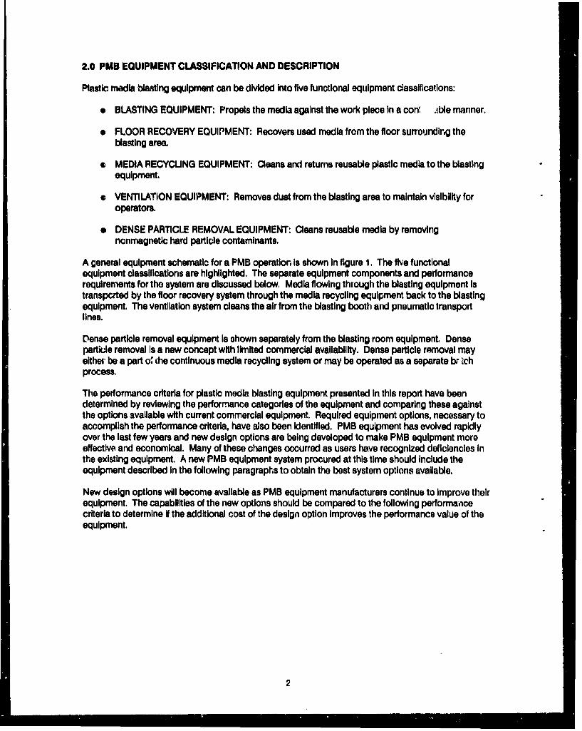
Plastic media blasting equipment can be divided Into five functional equipment classifications:
* BLASTING EQUIPMENT: Propels the media against the work piece In a coni ..ble manner.
* FLOOR RECOVERY EQUIPMENT: Recovers used media frcm the floor surroundirng theblasting area.
* MEDIA RECYCUNG EQUIPMENT: Cleans and returns reusable plastic media to the blastingequipment.
* VENTILATION EQUIPMENT: Removes dust from the blasting area to maintain visibility foroperators.
* DENSE PARTICLE REMOVAL EQUIPMENT: Cleans reusable media by removingnonmagnetic hard particle contaminants.
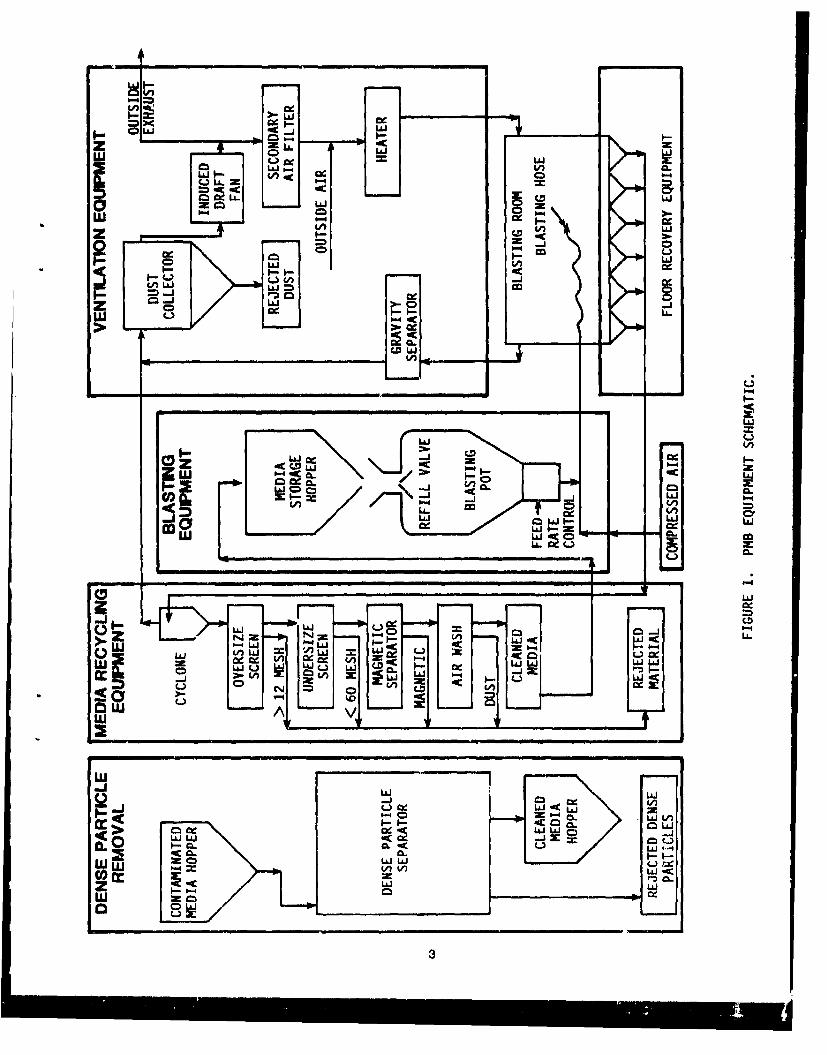
A general equipment schematic for a PMB operation Is shown In figure 1. The five functionalequipment classifications are highlighted. The separate equipment components and performancerequirements for the system are discussed below, Media flowing through the blasting equipment istransported by the floor recovery system through the media recycling equipment back to the blastingequipment. The ventilation system cleans the air from the blasting booth and pneumatic transportlines.
Dense particle removal equipment Is shown separately from the blasting room equipment. Denseparticle removal Is a new concept with limited commercial availability. Dense particle removal mayeither be a part o' the continuous media recycling system or may be operated as a separate b, ichprocess.
The performance criteria for plastic media blasting equipment presented in this report have beendetermined by reviewing the performance categories of the equipment and comparing these againstthe options available with current commercial equipment. Required equipment options, necessary toaccomplish the performance criteria, have also been Identified. PMB equipment has evolved rapidlyover the last few years and new design options are being developed to make PMB equipment moreeffective and economical. Many of these changes occurred as users have recognized deficiencies Inthe existing equipment. A new PMB equipment system procured at this time should include theequipment described In the following paragraphs to obtain the best system options available.
New design options will become available as PMB equipment manufacturers continue to Improve theirequipment. The capabilities of the new options should be compared to the following performanicecriteria to determine if the additional cost of the design option improves the performance value of theequipment.
2
ww
LAaJ
wLz
LLJ cL:
Ln I-
0l LIJ
LuL
-A )UCi
-j-I
LU L) L-4
w
_0 L L
3L
wI
3.0 BLASTING EQUIPMENT
Blasting equipment Is used to propel the media against the work piece In a controllable manner, TheIndividual performance requirements of the equipment are:
"* To store usable media for delivery to the work piece."* To meter the media Into the delivery system."* To transport the media to the blasting nozzle."* To propel the media against the work piece.
The usual blasting equipment furnished with a blasting enclosure Includes the following components:
"* Storage hopper"* Refill valve"* Blasting pot"* Blasting air regulator"* Media flow controller* Media and air mixing chamber"* Blasting hose"• Deadman switch"* Blasting nozzle
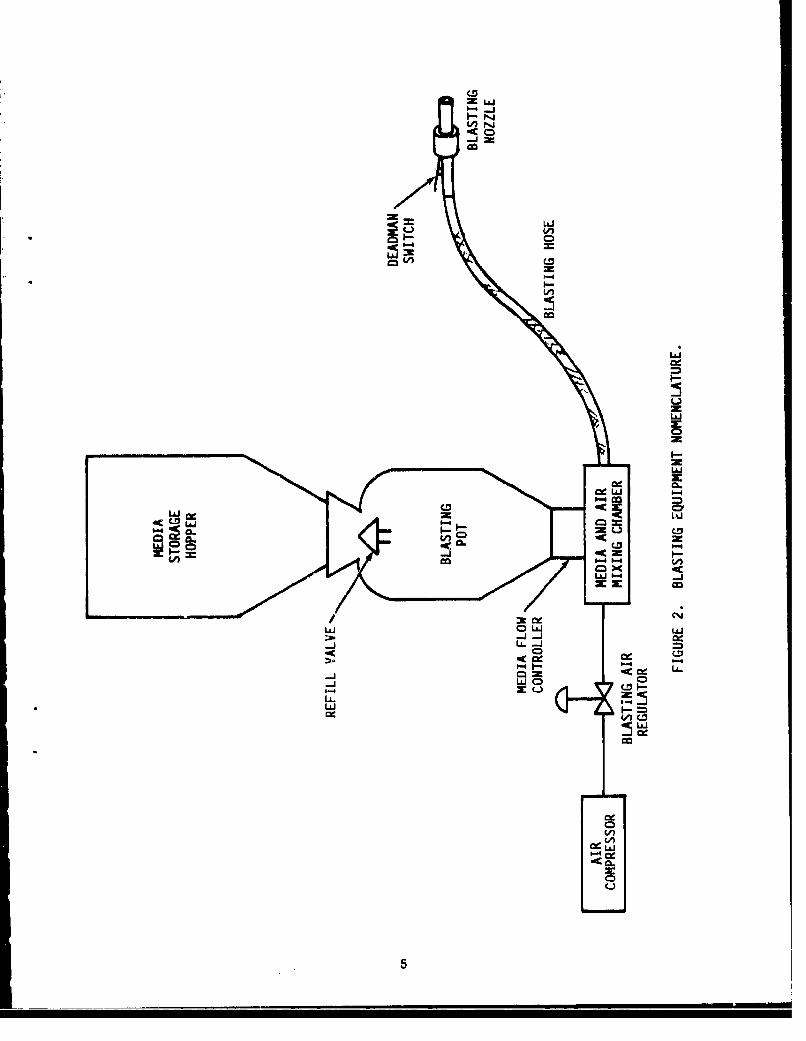
The blasting equipment Is used to control the important operating parameters of media particle speedand mass flow. Controlling the blasting operation Is Important to ensure successful coating removalwork without damaging the substrate. Equipment now L;sed to perform these functions has beendeveloped from existing sand blasting equipment. Typical equipment Is diagrammed In figure 2.
3.1 Blast Pot and Storage Hopper
A conventional pressurized sand blasting pot Is typically used to store the media prior to blasting. Thepot design has been altered from a 45 degree to a 60 degree bottom conical slope to ensure mediaflowing Into the bottom of the pot does not bridge over and stop flowing. The chamber Is filled withplastic media and compressed air Is supplied from an air compressor to provide the force to carry themedia through a hose to a blasting nozzle. The pressure is necessary in the blasting pot to equalizethe pressure in the blasting hose 3o that media will gravity flow to the mixing chamber, The mediastorage hopper holds the plastic media reserves to refill the blasting pot as necessary. The refill valveshould operate automatically each time blasting ceases. When the blasting pot Is depressurized, themedia weight on the cone shaped valve pushes it Into the blasting pot, allowing media to fall into it,When the blasting pot Is repressurized the air pressure overcomes the weight of the media and sealsthe blasting pot once again. The refill valve rhould not loak air when the pot is pressurized and shouldhave at least one elastomerlo surface to provlde a tight seal. The blasting pot access should becovered with a large mesh screen to prevent ontry of foreign material.
The volumes of the storage hopper and the blasting pot should be enough to prevent frequentinterruptions In the blasting process for medila refills. Ten minutes of uninterrupted blasting is areasonable minimum time period. The minimum usable volume for the blasting pot should be about3 cubic feet assuming a plastic media bulk density of 60 pounds per cubic ioot and one 0,5 inchblasting nozzle is used with a delivery rate of 20 pounds per minute. There should be a separateblasting pot for each blasting nozzle.
4
0-4 -1
r-4
owdo
LLiJ
LO)U
Lii
ILL
Liii
5c
The storage hopper should have a minimum volume of 6 cubic feet so that lost media has to bereplaced only once per shift. The volume of media losses during one shift are calculated using anassumed media degradation rate of five percent and a media mass flow rate of 7200 pounds for sixhours of blasting at 20 pounds per minute. The five percent loss (360 pounds) would occupy about6 cubic feet.
Media level Indicators are available for both the storage hopper and the blasting pot. The levelindicator Is required for the storage hopper, but is only a convenience on the blasting pot. The designpressure of the blasting pot should be a minimum of 110 pounds per square Inch (psig). The potshould be In accordance with the American Society of Mechanical Engineers (ASME), Section VIII,Pressure Vessel Code,
3.2 Media Metering System
Media from the blasting pot is metered into the blasting air stream at the media mixing chamber eitherby gravity flow through a variable orifice or by a mechanical metering system. The mass flow of mediathrough the delivery system affects the rate that material is removed from the coating. Erraetlcallypulsating media flows can damage sensitive work pieces by unexpectedly changing the mass flowrate. The media metering system should deliver between 0 and not less than of 20 pounds of mediaper minute with a 0.5 Inch bore nozzle. The media feed rate should be easily adjusted by the operator.Controls should be readily accessible to the operator if rapid transitions between different substratesare required.
Gravity metering systems use an orifice of varying size to allow different rates of media to fall Into thecompressed air stream and be transported to the blasting nozzle. At least one m'anufacturer uses asmall valve at the base of the blasting pot to vary the size of the hole so media can fall through Into thecompressed air stream. The differential pressure between the pot and the alrstream can also bevaried to alter the media flow. A higher pressure In the blasting pot than In the compressed air streamwill cause the media to be blown through the varying size orifice. Gravity feed systems should befurnished with an adjustable feed orifice valve marked to show its various positions. The differencebetween the pot pressure and the air line pressure should also be Indicated if this method Is used tohelp deliver media to the transport hose. Low media flow rates are difficult to reproduce with thisequipment due to lack of fine control.
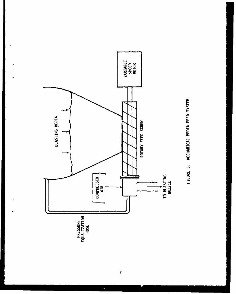
Mechanical media feed systems are designed to provide more consistent media flow rates thanpneumatic or gravity media feed mechanisms that are more likely to have erratic media flowpulsations, especially at lower blasting nozzle pressures. Flow rate accuracy can be reliablymaintained within -+-1 percent of the media flow rate setting. This kind of mechanical media flowcontroller is offered by at least one manufacturer In the form of the rotating screw feeder shown Infigure 3. A pressure equalizing hose should be furnished to avoid differential pressures across a rotaryscrew between the blasting pot and the transport hose. Media flow rates can be reliably controlled byvarying the rotational speed of the screw. Media discharged from the screw Is then transported to theblasting nozzle, Rotary valves are also used to meter media into the blasting air stream. Rotaryfeeders should be furnished with a variable speed motor and feed rate Indicator. Feed rates should beable to be varied from 10 to 100 percent of maximum media flow. The finer feed rate control of arotating media feeder is Important when blasting delicate substrates, especially on a production basiswhere rates must be accurately repeated.
6
-- j-
cr (A
LAJ
LLJ
K.L
LLLJX.w
0-4
4 ca4A -4
LaJV
7U
3.3 Media Delivery System
Ingressed stresses that may be Induced In substrates by the blasting process can be minimized bylowering the Impact speed of the particle. The lower speeds reduce the "oil canning" effectexperienced on some thin substrates. Particle speed is controlled by the differential pressure acrossthe blasting nozzle, Compressed air Is used to transport and propel the media through an abrasionresistant hose to the nozzle
By varying the air pressure used to transport the media, the pressure drop across the nozzle can bevaried. The larger the pressu 'e drop, the greater the air speed of the particles exiting the nozzle. Anair pressure gauge and regulator for adjusting the transport air and nozzle pressure should befurnished and easily adjusted by the operator. The control should be readily accessible to theoperator If rapid transistions between different substrates are required. The range of available airpressure normally extends from about 20 to 100 pounds per square Inch (psi), with typical maximumoperating pressures of 40 to 50 psi during normal operations.
To attain accelerated particle speeds venturl style sand blasting nozzles are usually used for PMB.Nozzles should be easily replaceable In threaded nozzle holders, The nozzle connection should adaptto nozzles with up to 0.6 inch diameter bores. Smaller diameter bore nozzles should be available fordelicate blasting work at low media flow rates and air pressures. The nozzle connection at the end ofthe hose should be fitted with an OSHA required dead man switch that Immediately stops media flowthrough the nozzle when not held open by the operator.
The blasting hose should be electrically grounded to eliminate static electricity. The hose should alsobe lightweight, weighing less than 0.7 pounds per foot to minimize operator fatigue. It should be fittedwith a swivel If the blasting nozzle cannot rotate freely when being used with special attachments atthe nozzle, These attachments can Include optional lights or operating controls.
3.4 Wheel Blasting Systems
A completely different type of blasting equipment Is based on a high speed rotating wheel to propelmedia; compressed air Is not used, One wheel can output the same amount of media as six to tenblasting nozzles. The whee! uses about 10 percent of the energy that the group of nozzles would useto eject the same amount of media against the work piece. One manufacturer has adapted theprocess to PMB applications. Figure 4 Is a schematic of a wheel blasting system,
Media Is gravity fed through a hose to the center of the rotating wheel, travels through a positioninggate and is then propelled by centrifugal force to the outside of the wheel, The angular momentum ofthe media Is Increased during this travel until the particles are flung off the wheel's edge. Thepositioning gate ensures that media Is Introduced to the center of the wheel. Particles positioned atthe center of the wheel must travel an equivalent path across the wheel before being expelled from theedge, Since radial vanes are usec to further control the movement of the particles within the wheel,the stream actually exhibits a high speed pulsating flow. The pulsation frequency is high enough tosimulate a steady media flow pattern. The velocity of tt.e particles can be varied by adjusting thetotation.,I sp"ed of the wheel. Wheel blast systems should, therefore, be furnished with variable ratiomotor to wheel couplings. In order to observe the wheel blast pattern, a section of cardboard wassubjected to one pass of the wheel. The outside edges of the pass were lightly blasted, The particlesremoved Increasing amounts of the cardboard toward the center of the blast pattern Indicating that theblasting effect Is not consistent across the whole of the blast pattern, This pattern should be furtherInvestigated to ensure that sensitive substrates are not damaged by the unevenness of the wheel blastpattern.
8
Blastlr- wheels are heavy and difficult to control manually. Their higher rates of media flow, however,are useful In large automated blasting systems. An automated system elimlrktes variations Inoperating parameters such as dwell time, angle of Incidence, stand-off distance, etc. Someautomated multiple wheel systems, such as the helicopter blade stripping machine used byAerospatlals In France, use a series of cameras to determine the degree of paint removal. Thecameras provide feedback that controls the operation of the blast wheels. This type of system canmaintain adequate coating removal rates at the low media particle speeds required for delicatesubstrates and Is most economically applied to large repetitive blasting projects.
9
4.0 FLOOR RECOVERY EQUIPMENT
Performance requirements of the equipment recovering material from the floor surrounding theblastlng area are:
"* To remove blasting debris from the floor in a continuous or semicontinuous manner."* To structurally support the work piece and personnel In the blasting area."* To transport the debris/reusable media mixture to the recycling equipment,
The floor recovery equipment may include the following components:
* Floor grating* Support beams* Media collection device* Media transport device* Media transport ductwork* Device to prevent damage to the equipment by large foreign objects.
The floor recovery equipment gathers the used media, paint chips, and other material from theblasting room by collecting debris as It falls through steel grating placed across a set of supportbeams. Mechanical or pneumatic conveying systems are Installed under the floor grating to transportmaterial to the recycling equipment. The floor recovery system can either be a full floor recoverysystem with the entire floor covered by grating or a partial recovery floor with only a fraction of thefloor covered by grating.
4.1 Description of Full and Partial Floor Recovery Equipment
The performance requirements of the floor media recovery equipment are simple enough to beaccomplished by a variety of commercially available methods. The capital and operating costs of thesystem are Important factors In selecting the appropriate design, Full floor recovery systems are moreexpensive than partial floor recovery systems but require less operator labor, Recovery pits orpneumatic dust pans require minimal capital investment but have the highest operating costs,Whatever the system selected, it should not destroy reusable media when In operation. The blastingdebris recovery and transport rate should be at least twice the maximum flow of media from theblasting nozzles to prevent operating bottlenecks. The systems should be Immune to plugging whenfully loaded with media,
No investment in floor recovery equipment will require operators to sweep the material from a solidfloor and carry it to the media recycling system. Labor inefficiencies caused by personnel working inthe bulky protective clothing and breathing air supply hoses required for PMB work causes the cost oflabor to perform this recovery work to be high. Floor recovery equipment can be added to minimizethese labor costs, The time that operators are sweeping the floor is not only expensive, but it is alsotime when blasting work cannot be performed. The equipment owner should evaluate the capital andoperating costs to determine which of the several system improvements are economically justified.Full floor recovery systems are able to return media to the recycling equipment no matter where itfalls. The additional cost of a full floor recovery system in larger PMB enclosures, however, does notappear to be economically justified by the labor cost savings.
10
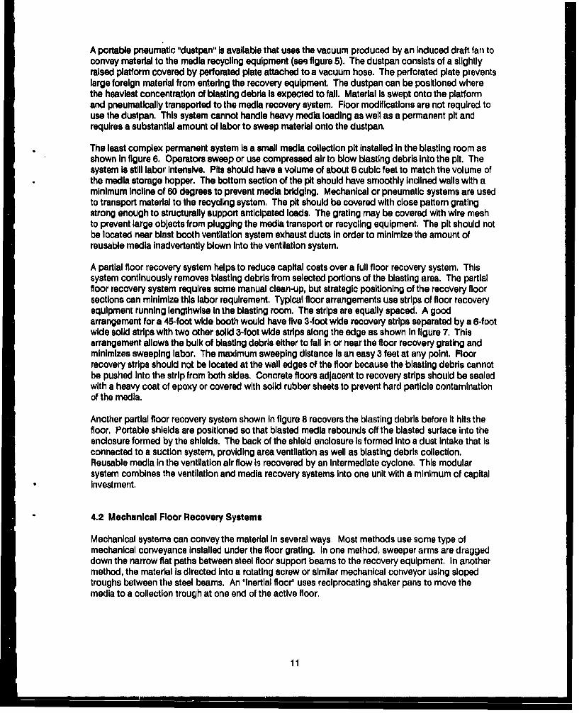
A portable pneumatic "dustpan" Is available that uses the vacuum produced by an Induced draft fan toconvey material to the media recycling equipment (see figure 5). The dustpan consists of a slightlyraised platform covered by perforated plate attached to a vacuum hose. The perforated plate preventslarge foreign material from entering the recovery equipment, The dustpan can be positioned wherethe heaviest concentration of blasting debris Is expected to fall. Material Is swept onto the platformand pneumatically transported to the media recovery system. Floor modifications are not required touse the dustpan. This system cannot handle heavy media loading as well as a permanent pit andrequires a substantial amount of labor to sweep material onto the dustpan.
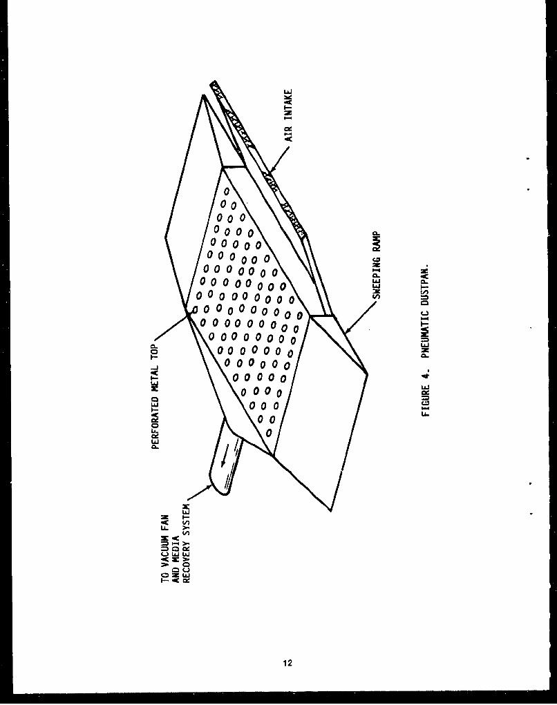
The least complex permanent system Is a small media collection pit Installed In the blasting room asshown In figure 6. Operators sweep or use compressed air to blow blasting debris into the pit. Thesystem Is still labor Intensive. Pits should have a volume of about 6 cubic feet to match the volume ofthe media storage hopper. The bottom section of the pit should have smoothly Inclined walls with aminimum Incline of 60 degrees to prevent media bridging. Mechanical or pneumatic systems are usedto transport material to the recycling system. The pit should be covered with close pattern gratingstrong enough to structurally support anticipated loads, The grating may be covered with wire meshto prevent large objects from plugging the media transport or recycling equipment. The pit should notbe located near blast booth ventilation system exhaust ducts In order to minimize the amount ofreusable media Inadvertently blown Into the ventilation system.
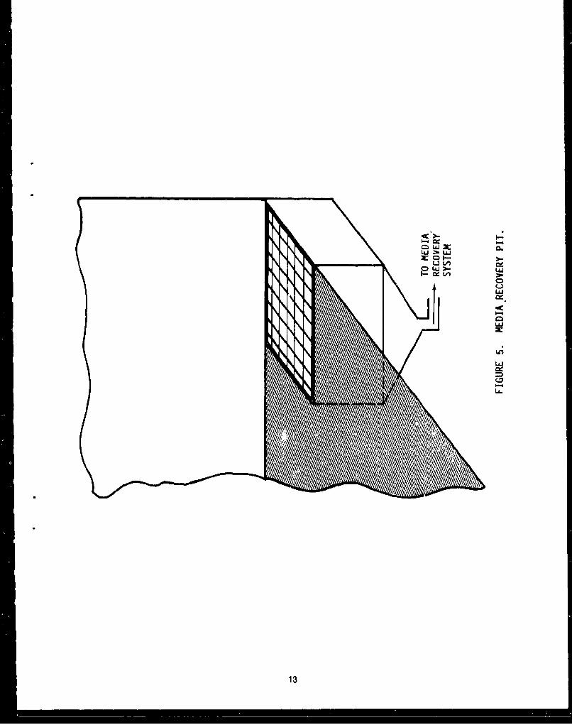
A partial floor recovery system helps to reduce capital costs over a full floor recovery system. Thissystem continuously removes blasting debris from selected portions of the blasting area. The partialfloor recovery system requires some manual clean-up, but strategic positioning of the recovery floorsections can minimize this labor requirement. Typical floor arrangements use strips of floor recoveryequipment running lengthwise In the blasting room. The strips are equally spaced. A goodarrangement for a 45-foot wide booth would have five 3-foot wide recovery strips separated by a 6-footwide solid strips with two other solid 3-foot wide strips along the edge as shown In figure 7. Thisarrangement allows the bulk of blasting debris either to fall In or near the floor recovery grating andminimizes sweeping labor. The maximum sweeping distance Is an easy 3 feet at any point. Floorrecovery strips should not be located at the wall edges of the floor because the blasting debris cannotbe pushed Into the strip from both sides. Concrete floors adjacent to recovery strips should be sealedwith a heavy coat of epoxy or covered with solid rubber sheets to prevent hard particle contaminationof the media.
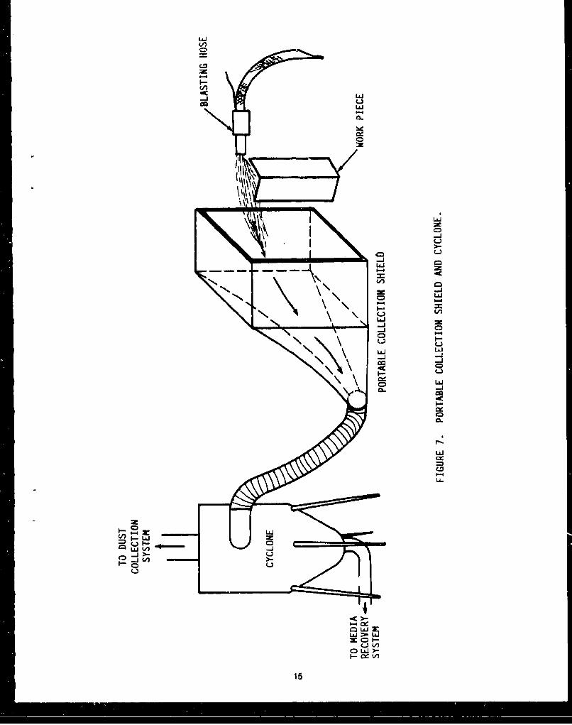
Another partial floor recovery system shown In figure 8 recovers the blasting debris before it hits thefloor. Portable shields are positioned so that blasted media rebounds off the blasted surface Into theenclosure formed by the shields. The back of the shield enclosure Is formed into a dust Intake that isconnected to a suction system, providing area ventilation as well as blasting debris collection.Reusable media In the ventilation air flow Is recovered by an Intermediate cyclone. This modularsystem combines the ventilation and media recovery systems Into one unit with a minimum of capitalInvestment.
4.2 Mechanical Floor Recovery Systems
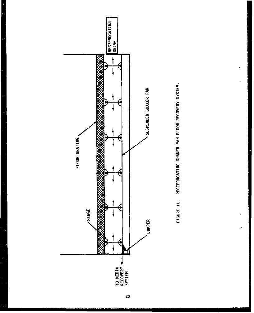
Mechanical systems can convey the material In several ways. Most methods use some type ofmechanical conveyance Installed under the floor grating. In one method, sweeper arms are draggeddown the narrow flat paths between steel floor support beams to the recovery equipment. In anothermethod, the material Is directed Into a rotating screw or similar mechanical conveyor using slopedtroughs between the steel beams. An "Inertial floor" uses reciprocating shaker pans to move themedia to a collection trough at one end of the active floor.
11
Ij.J
I--
000
0o 000000000000
000000000000000 -0 0 00000 0 •
000000o00000000000 I-:
o0 00 00000 =000000 0.
I0 0 0 00L-J
•. 00000
000
0CLi
. v)•>.LA --•JU
ziiS0
ow
12
CD.L&J
w
I-D
LL.
13
IL mn
I LAJ3c
r14
La LL )
LLLaLLU L6
LPa4t'0 Lai
LaJ
(si LozL6
-cic
L&'Ct - La.
00H 0
00CL
LaOJ
O~ad
~~0 W
144
L~J
0-4
1--J
Uý-ID--
LL-J
CD
OLAJE:
LJ~CL
UL')JOLAJ)-
15.
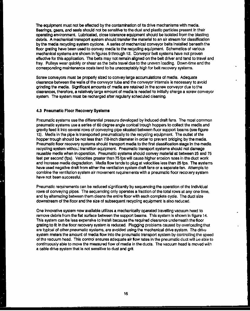
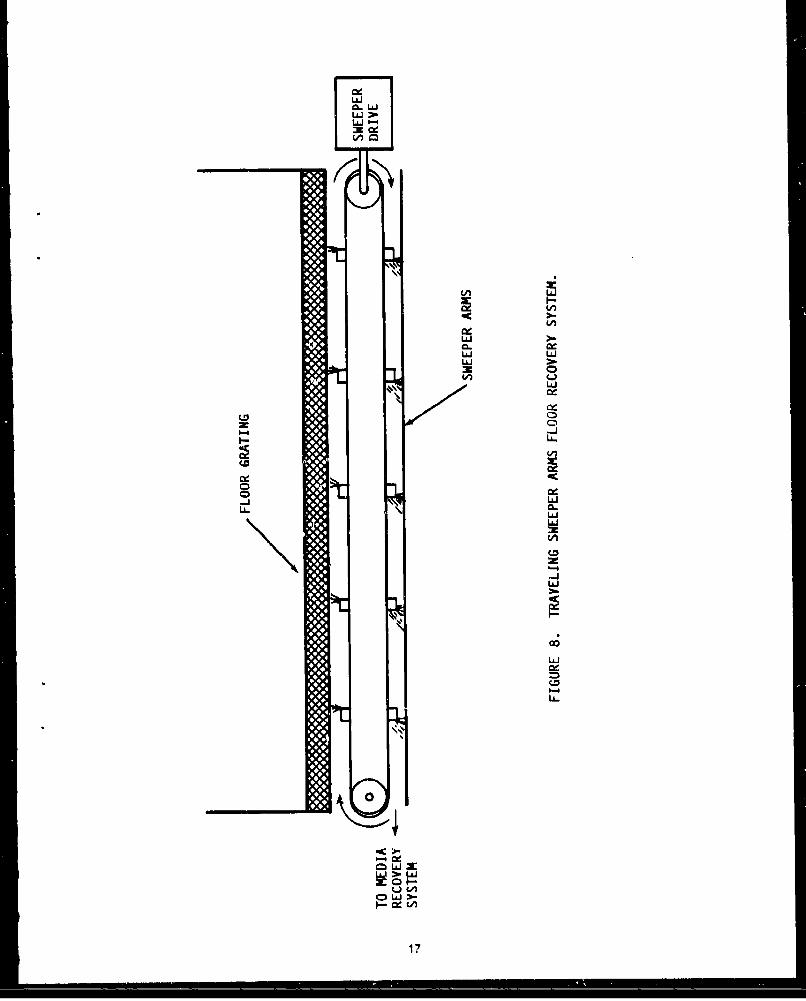
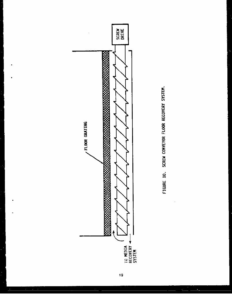
The equipment must not be effected by the contamination of its drive mechanisms with media.Bearings, gears, and seals should not be sensitive to the dust and plastic particles present in theiroperating environment. Lubricated, close tolerance equipment should be Isolated from the blastingdebris. A mechanical transport system should transfer the material to an air stream for classificationby the media recycling system cyclone. A series of mechanical conveyor belts installed beneath thefloor grating have been used to convey media to the recycling equipment. Schematics of variousmechanical systems are shown In figures 9 through 12. Conveyor belt systems have not proveneffective for this application. The belts may not remain aligned on the belt driver and tend to travel andfray. Pulleys wear quickly or shear as the belts travel due to the uneven loading. Down-time and thecorresponding maintenance costs tend to be unacceptably high for belt recovery systems.
Screw conveyors must be properly sized to convey large accumulations of media. Adequateclearance between the walls of the conveyor tube and the conveyor Internals Is necessary to avoidgrinding the media. Significant amounts of media are retained In the screw conveyor due to theclearances, therefore, a relatively large amount of media is needed to initially charge a screw conveyorsystem, The system must be recharged after regularly scheduled cleaning,
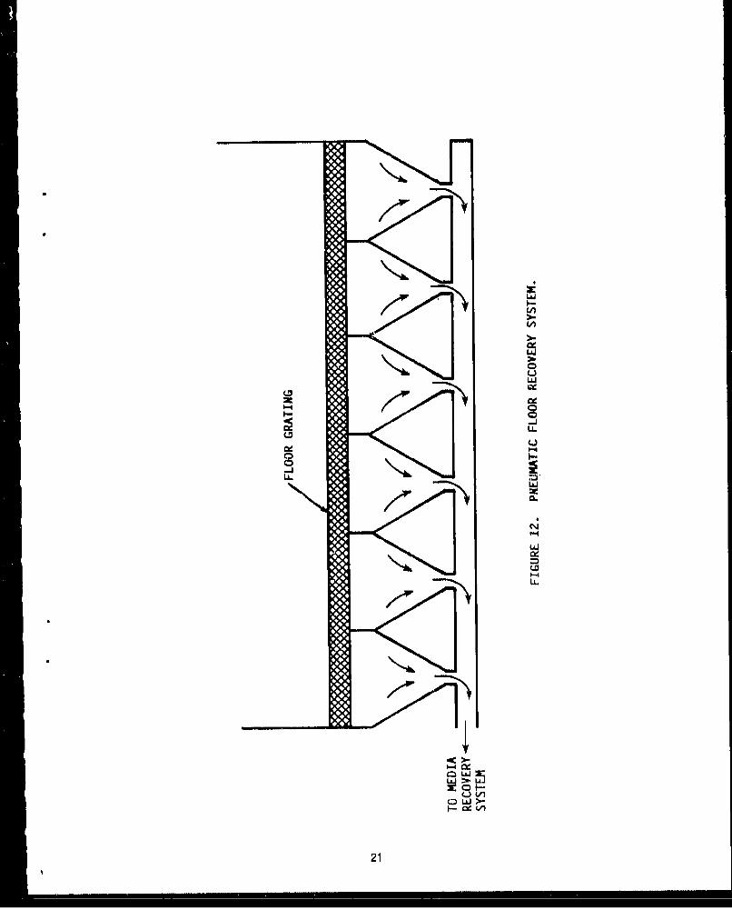
4.3 Pneumatic Floor Recovery Systems
Pneumatic systems use the differential pressure developed by induced draft fans. The most commonpneumatic systems use a series of 60 degree angle conical trough hoppers to collect the media andgravity feed It Into several rows of conveying pipe situated between fluor support beams (see figure13), Media In the pipe is transported pneumatically to the recycling equipment. The outlet of thehopper trough should be not less than 7/8-Inch diameter in order to prevent bridging by the media.Pneumatic floor recovery systems should transport media to the first classification stage in the mediarecycling system withOLr transition equipment. Pneumatic transport systems should not damagereusable media when In operation. Pneumatic systems should convey material at between 25 and 75feet per second (fps). Velocities greater than 75 fps will cause higher erosion rates In the duct workand Increase media degradation. Media flow tends to plug at velocities less than 25 fps. The systemshave used negative draft from either the ventilation system draft fans or a separate fan. Attempts tocombine the ventilation system air movement ruquirements with a pneumatic floor recovery systemhave not been successful.
Pneumatic requirements can be reduced s~gnificantly by sequencing the operation of the Individualrows of conveying pipes. The sequencing only operates a fraction of the total rows at any one time,and by alternating between them cleans the entire floor with each complete cycle. The duct sizedownstream of the floor and the size of subsequent recycling equipment is also reduced.
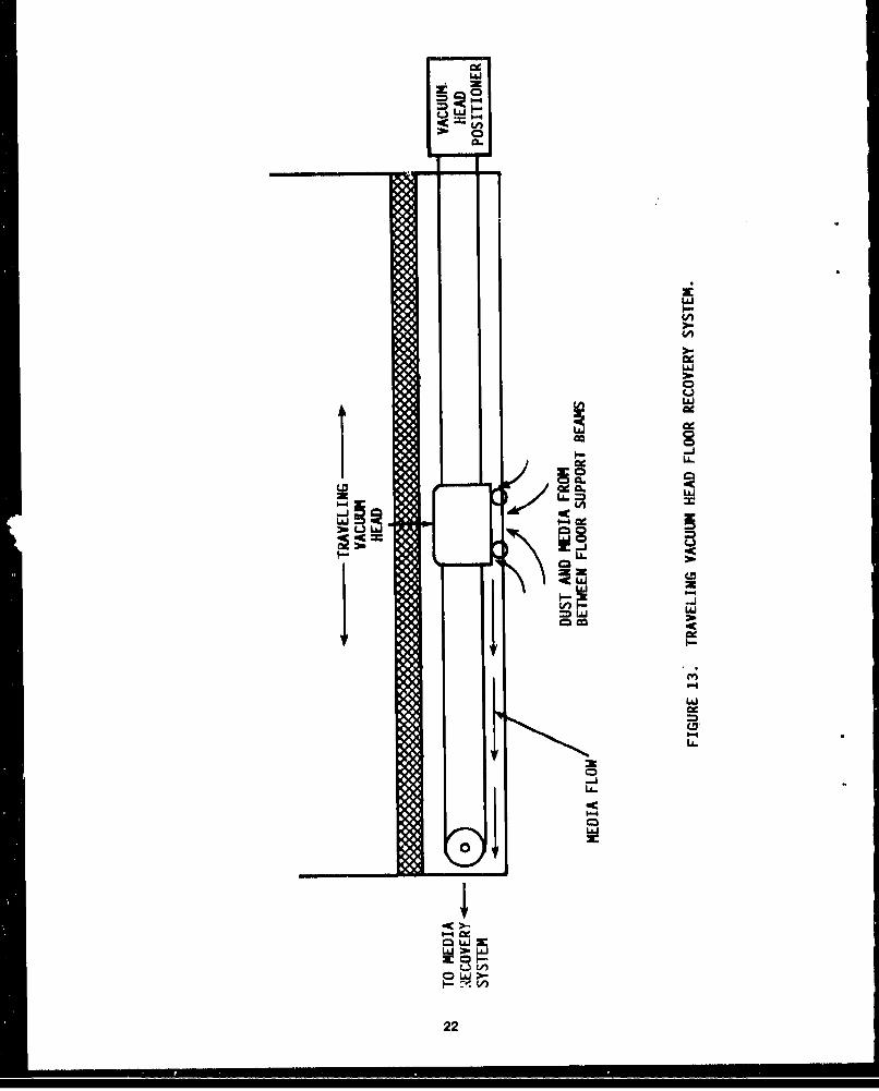
One Innovative system now available utilizes a mechanically operated travelling vacuum head toremove debris from the flat surface between the support beams. This system Is shown In figure 14.This system can be less expensive to Install because the required clearance underneath the floorgrating to fit In the floor recovery system is reduced. Plugging problems caused by overloading thatare typical of other pneumatic systems, are avoided using the mechanical drive system. The drivesystem meters the amount of media flow Into the pneumatic transport system by controlling the speedof th3 vacuum head. This control ensures adequate air flow rates In the pneumatic duct will be able tocontinuously able to move the measured flow of media in the ducts. The vacuum head Is moved witha cable drive system that is not sensitive to dust and grit,
16
LLAJ
'-4 -J4
I-L
cmD
ILL
LLI
-4-J
ILL
IL.
CC
17
LiJ
I-ZIP
-I-..LLJ
:Imp
V))
LJ~
M LAJ
uj -Izec
too)
)I-V)
:lob
:-a
LO
U-)
x 0
I- CX -
19,
t-4
126L&J
CA,
L&J
L&J
Wi LOJM c
LiLL.
-LJ
01000
U.,
P-4-
LCAiJ
20
LO'
Cd,
e.-
LL
Lw.
214
LA(A
Qw
LLI
LL.~
-JALNib
"VLL
I-. c~ 39
22-
5.0 MEDIA RECYCUNG EQUIPMENT
Media recycling equipment cleans and returns reusable plastic media to the blasting equipment. Theperformance requirements of the equipment are:
"* To accept the material being transported from the floor recovery system."* To collect the material being transported from the ventilation system large particle separator."* To remove particles greater than 10 mesh (Tyler equivalent scale) from the reusable media
stream."* To remove particles less than 60 mesh (Tyler equivalent scale) from the reusable media
stream."* To remove magnetic particles from the reusable media stream.* To transport properly classified reusable media to the blasting equipment storage hopper."* To collect the non-reusable portion of the blasting debris for disposal.
An efficient media recycling system Is the key element in a cost effective blasting operation. Mediamust be cleaned to prevent substrate damage and maintain efficient operation. However, properlysized reusable media should not be discarded In the cleaning process. The annual operating expensefor replacing lost media at $1.60 per pound can easily be greater than the capital cost of theseparation equipment. A recycllni system for a single 0.5 inch nozzle (20 pounds per minute)operating six hours per day, five days per week, with three percent recoverable media loss per cycle(over and above the typical 5 percent degradation loss) will require almost $90,000 annually for mediareplacement costs.
The media recycling equipment may Include the following components:
* Cyclone separator(s).e Collection hopper for returned media.* Rotary valve,* Vibrating or stationary screens.o Magnetic separator.* Air wash.* Mechanical elevators.e Pneumatic transport systems.* Rejected debris collection trays, bins or bags.
To minimize media replacement costs, the particles discarded by the entire recycling equipmentIncluding cyclones, jlbratlng screens, air washes, and magnetic separators should contain less than 5percent by weight reusable plastic media large enough to be retained on a 60 mesh screen. Therecycling equipment should effectively clean the media. Reusable media should contain less than 5percent by weight particles small enough to pass through a 60 mesh screen,
5.1 Cyclone Separators and Rotary Valves
Tho Initial media recycling step, usually accomplished by a cyclone separation, Is to remove dust fromthe material collected from the blasting area. The dust from the cyclone Is transported to a baghouse.Initial removal of the dust helps to prevent plugging later In the recycling process. The cyclone Is alsouseful in agitating and removing dust adhering to reusable media. Manufacturers have tended toundersize this cyclone resulting In reusable media being lost to the baghouse, An adequately sizedcyclone separator should be used to remove fine particles from the material stream.
23
A recently marketed cyclone design combini a partial cyclone for classifeoation with a particle airwash. After media enters the cyclone, air Is Introduced In a narrow strearrI flowing at high velocityperpendicular to the direction of the media particle flow. This effect helps remove any dust that mightbe entrained with the reusable media and transports it to the baghouse. This classification system hasproven to be highly efficient In meeting media recycling requirements In the newer PMB equipment.The rate of air passing through the air wash should be adjustable to provide optimum results.
Rotary valves can be used to provide an aldock during transfer of media between recycling systemcomponents operating at different pressures. A typical rotary valve location is at the bottom of thecyclone collection hopper. Rotary valves can also be used to meter a constant flow of plastic mediato the recycling equipment.
5.2 Vibrating Screens
The material recovered in the cyclone is then classified to isolate the particles between 12 and 60mesh. A variety of equipment can be used for this purpose. A secondary cyclone, or a vibrating orrotating screen, are currently the preferred secondary classification equipment.
A two-tier vibrating screen Is frequently selected to classify the material. A 12 mesh top screencollects the oversize material while a 60 mesh bottom screen separates the undersize material. Theseundersize fractions are then rejected to a collector. The 12 to 60 mesh fraction collected on thebottom 60 mesh screen is then routed to the media storage hopper. The vibrating screen capacityshould be sized to avoid plugging or overloading the screens. The screen should preferentially becleaned automatically in a blast room. An oversized screen should be manually cleaned in a glovebox.
S.3 Magnetic Separator
An adequately sized magnetic separator should be positioned in the media flow stream to removetramp metal from the classified media. Magnetic material can enter the recycle stream as a result ofnew media contamination, poor housekeeping, substrate erosion, or erosion of steel portions of theplastic media recovery/recycling system. The harder metal particles circulating through the systemcan damage the substrates during blasting.
A variety of magnetic separators are available from manufacturers and may Incorporate eitherautomatically-cleaned electromagnets or manually-cleaned permanent magnets. One PMB systemuses a magnet approximately one square inch In slze located in the throat of the blasting pot. Othermanufacturers Install larger permanent magnetic separators, which still require manual effort to clean.The magnetic separator should be automatically self-cleaning to ensure its effectiveness. Manuallycleaned separators (permanent magnets) tend to be Ignored and, thus, lose their effectiveness overtime as their magnetic particle retention capacity Is excended.
One manufacturer has produced a satisfactory automatic, continuously-cleaned magnetic separatorby using a partially magnetized rotating drum, The drum Is magnetized where the media contacts it.Magnetic material Is retained on the drum and rotates away from the media path. As the drum rotates,the magnetic field Is deenergIzed and the magnetic ir aterial fails Into a separate hopper for disposal.Commercially available, self cleaning magnetic separators remove greater than 35 weight percent perpass of the magnetic particle contamination in the media (see paragraph 9.1.2). Other design optionsshould be explored to Improve this efficiency.
24
5.4 Miscellaneous Equipment
The cyclone, vibrating screen, and magnetic separator should discard the rejected material into astorage bin or hopper that can be emptied with a minimum exposure of personnel to the material.
All access doors to the ventilation equipment should be fitted with rubber gaskets to prevent dustleaks Into the room where unprotected personnel may be working. The access doors should beequipped with interlocks to prevent operation of the blasting equipment when the doors are open.
Electrical equipment located outside of the blasting enclosure should be housed in Class II, Division II,NEMA type 9 enclosures, unless the operating area requires a more stringent electrical classification.
Both mechanical and pneumatic methods are acceptable to convey media through the recyclingsystem. Mechanical transport devices, such as bucket elevators, may reduce energy consumptionand minimize media damage as compared to pneumatic systems. Pneumatic transport systemsshould not use thin-walled, wire-reinforced flexible ducts due to their rapid failure under normaloperating conditions from media erosion.
25
6.0 VENTILATION EQUIPMENT
The ventilation equipment removes dust from the blasting area to allow work piece visibility. Theperformance requirements of the equipment are:
"* To minimize personnel exposure to toxic materials and minimize explosion hazards."* To remove dust from the work piece area during blasting in a manner ensuring good visibility."* To capture dust entrained In the ventilation air stream for disposal."* To return reusable media entrained in the ventilation air back to the system for recycling."* Condition air for personnel safety and comfort.
The usual equipment Included In a ventilation system may include the following components:
"* Ductwork to/from blasting room and recovery equipment."* Gravity separation chamber."* Baghouse."* Induced draft fan."* Ventilation control dampers."* Exhaust ductwork."* Dust collection hopper.
6.1 General Description of Ventilation Systems
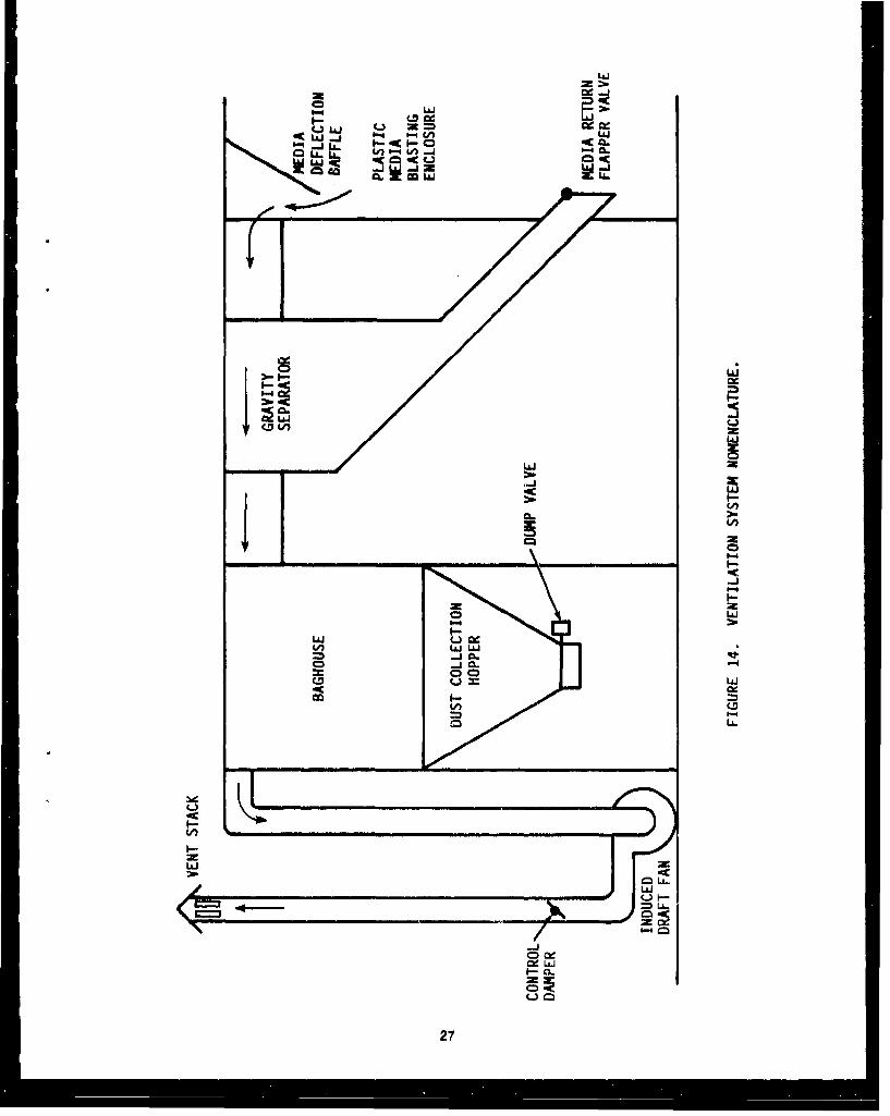
Ventilation equipment designs have been progressing to a relatively constant configuration. Air flowsInto the blasting booth from one side, traverses the blasting chamber, and exits at the other side Into acyclone system. Fines from the recycling system then travel to a baghouse. An Induced draft fanlocated downstream of the baghouse moves the air through the system and discharges it to n ventstack, The basic system Is shown In figure 15,
The Naval Energy and Environmental Support Activity (NEESA) has developed ventilation systemdesign guidance for PMB Installations, NEESA Indicates that based on ANSI Z9.4-1985, 29CFR1910.94 (OSHA), and MIL-HDBK 1003/17 (Industrial Ventilation Systems), PMB enclosures using acrossdraft flow pattern must have air velocities of 100 feet per minute (FPM) since coatings containinglead and chromates are being removed. Operational tests have indicated that velocities ofapproximately 60 fpm In large booths have maintained good visibility, Operators are always equippedwith OSHA/MSHA approved blasting hoods with supplied breathling air and are not exposed tohazardous concentrations of toxic materials.
The air flow rate also varies across the cross section of the blasting room. Air speeds are muchgreater In the center of the room where the blasting work Is likely to be performed. The nominal crosssection air flow calculation also does not account for the effect of air flow obstructions by the workpiece and personnel In the booth. The obstructions would decrease the cross sectional area andincrease local velocities at the work piece. The obstructions also create turbulance making laminar airflow difficult to maintain.
The exit ductwork from the blasting area should be designed to minimize the amount of reusablemedia entrained In the air stream. Several manufacturers have Installed baffles on the ductwork Inletsto deflect media back to the blasting floor. The average velocity in the ventilation ducts should benbout 3000 feet per minute (fpm) to minimize erosion damage and prevent accumulations of dustwt¶hin the ductwork. A seldom used, but effective design, places a gravity separation chamber in theexit ductwork to remove media from the air stream. A slanted pipe equipped with a flapper valve Isused to return media to the blasting area from the gravity separation chamber.
28
LLjJ
-~ LiJI-b
i- LA.
-j
IA;
2c2
000
L&JJ
(A~c LiJJJq
0 CD
00
Cyclones separators may also be used to remove media from the ventilation air before it Is trapped inand discarded by the baghouse, Dust laden air gathered from other cyclones In the system Is routedto the baghouse.
The baghouses selected to remove dust should be of the reverse pulse style using either cartridge orbag filter elements. The reverse pulse units use bursts of compressed air to dislodge contaminants onthe filter elements. The operation of the reverse pulse mechanism should be automatic. Themechanism should be activated by the differential pressure across the filter element or by a timer witha differential pressure switch override. The timer and the differential pressure switch settings shouldbe adjustable. The dust then falls to the bottom of the baghouse for collection and disposal. Filtervelocity Is defined as the ratio of the airflow rate to the available filter area. Baghouses should use filtervelocities with an air-to-cloth ratio of less than 3,0.
Cartridge filter elements are usually the economical choice for small Installations, Adequate accesshatches should be provided to easily replace cartridge filter elements and provide normalmaintenance, Platforms should be provided for all elevated acces% hatches.
The dust collection hopper for the baghouse should be designed io minimize exposure of personnel tothe dust during removal operations. The hopper should be furnighed with an isolation valve and a dustcollection system that will work In the slight vacuum caused by the draft fan, The dust hopper shouldbe furnished with a level Indicator to Indicate when it is full.
The Induced draft fans tend to be adequately designed and sized for the commercially availableequipment. The fan should be located downstream of the dust collector. Sufficient draft should beinduced to provide the required air velocities In the blasting area. The air discharged from the fanshould usually be routed outside the building enclosing the PMB booth and equipment especially Ifunprotected personnel may be exposed.
Ventilation air will usually require conditioning to avoid problems caused by the ambient temperatureand humidity. Low temperatures may Increase the brittleness of the substrates being blasted and alsoreduce media life, High temperatures may increase operator fatigue and decrease productivity. Highhumidity may cause media agglomeration leading to problems In the media recovery and recyclingequipment. The design of the HVAC equipment should minimize the energy costs associated withheating or cooling the ventilation air,
28
7.0 DENSE PARTICLE REMOVAL EQUIPMENT
The purpose of dense particle removal equipment Is to remove particles more dense than the plasticmedia that are of the same size as the plastic media and able to pass through the media classificationsystem. The dense, hard particles may cause damage to sensitive substrates if allowed to remain Inthe plastic media. The Individual performance requirements of this equipment are:
* To remove particles of significantly higher specific gravity that are In the same size range asthe reusable plastic media.
o To dry or otherwise reverse the effects of *he separation process on the reusable plasticmedia.
o To collect the denser particles for disposal.
The dense particle removal equipment can Include the following components for a flotation-stylecleaning system: (Manufacturers may not supply all of the components listed or may supplyalternates.)
"* Media storage hopper"* Media Jellvery system"* Tiered flotation tank"* Circulation pump"* Media collection screen"* Media dryer"* Cleaned media storage hopper"* Fluid cleaning system
The hard particles, although denser than plastic, still fall in the size classification range between 12 and60 mesh. For example, a 20 mesh plastic media particle has about the same weight as a 24 meshsand particle or a 32 mesh stainless steel particle. The almost 300 to 1 volume ratio between 12 and60 mesh particles easily masks the relative density ratios of 6 to 1 between metal particles and plasticmedia. The cyclone, sieving, and air wash recycling operations are not discriminating enough toremove the hard particle contaminants. The Air Force recommends not greater than 200 ppm byweight concentration of hard particle contamination In recycled media. Dense particle removalequipment is still being developed and is only marginally available on a commercial basis,
7.1 General Description of Dense Particle Removal Equipment
The performance criteria for dense particle separation eqi ilpment is to provide dry media free fromdense particles for use In subsequent blasting operation, The media should be dry to prevent cakingor plugging of the blasting system. The concentration of dense particles remaining In the mediashould be not greater than 200 ppm weight percent of the cleaned media.
One possible media cleaning system uses a flotation system where the dense particles sink away fromthe floating plastic media particles. The media to be cleaned Is placed In the media storage hopperand metered Into the flotation tank. Freon has been used as a possible flotation fluid because Itsspecific gravity Is between that of the plastic media and the hard particles. The flotation fluid Iscirculated to help carry the media across weirs while sand and other particles sink to the bottom of theIndividual chambers. Fluid reaching one end of the tank Is screened to remove impurities andreturned to the tank, The plastic media floats onto a separation screen and falls into a heated screwconveyor to be dried and transported to the cleaned media storage hopper.
29
AltMough effective, the envlronmental sensitivity of freon will probably prevent its use as a commercialflotation agent. Freon, along with other chlorofluorocarbons (CFC) have been Implicated in thedegradation of atmospheric ozone. The liquid Is also expensive and will have significant operationallosses due to high evaporation rates. Alternate methods such as water washing techniques arecurrently being developed. It Is also possible that substitute flotation agents may be Identified.
Tabling Is one equipment option now used In the mining Industry for density separations. A media andwater slurry Is poured over a moving ried tabletop. The heavier particles tend to remain In the rifflesend travel along them to a side of the table, while the lighter plastic particles travel over the rifflesacross the table. The plastic media Is then dried and transported to a storage hopper. Theeffectiveness of this process depends mainly on the difference In specific gravity between thecontaminants and the plastic media.
Dense particle separation equipment installations are an economic choice of the equipment owner.The equipment owner must balance the replacement costs of reusable media dl3carded due to hardparticle contamination against the capital and operating costs of a dense particle removal system. Anadditional factor Is the cost of damaged parts due to unanticipated hard particle contamination.
30
6.0 PLASTIC MEDIA BLASTING GLOVEBOX
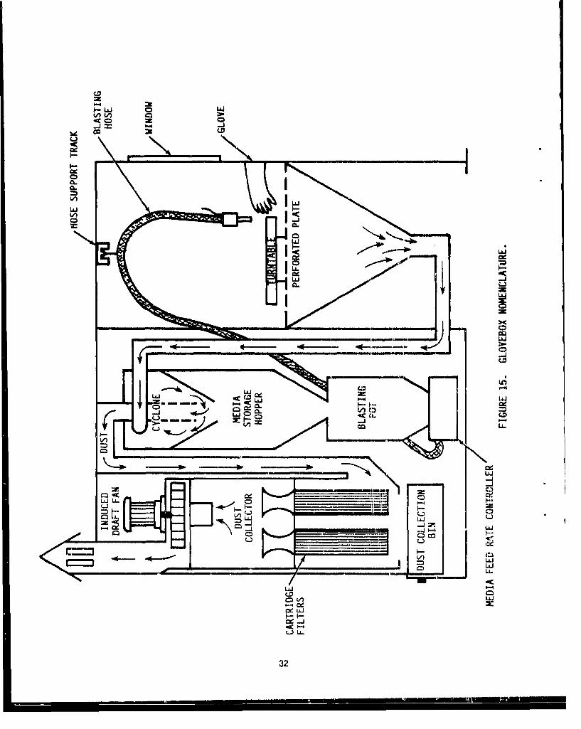
Plastic media blasting in a glovebox Is simpler than full scale blast booths due to the reduced scale ofoperation. Four of the five functional equipment classifications are highlighted. The dense particleremoval equipment Is not shown, as it Is similar to what would be used to clean media from a blastingroom. The Individual equipment components for the system are discussed below. Figure 16 is aschematic of a glovebox.
8.1 Blasting Equipment
The blas!.-,j equipment for a glovebox Is similar to the equipment used In a blasting room. Theblasting pot and media storage hopper are, however, usually smaller. The glovebox Is equipped withlatex gloves and working surface. A turntable should be furnished to improve accessibility to theworkplece. The blasting hose may be suspended from an Internal roof track for easier handling.
8.2 Floor Recovery Equipment
The media recovery equipment for a glovebox typically consists only of a work area of perforatedmetal. Blasting debris fall through the perfoiatlons to a conical section with a vacuum Intake at thebottom of the cone. Suction is provided by the baghouse Induced draft fan. The blasting debris isthen conveyed to a cyclone separator.
8.3 Media Recycling Equipment
A small cyclone separator Is usually provided and can be equipped with an efficient air wash at itsoutlet to fully remove dust from the reusable media without a vibrating screen. A stationary, manuallycleaned perforated metal screen at the cyclone outlet can collect oversized material as reusable mediafails across it Into a storage hopper, Gloveboxes are also furnished with small media recyclingsystems equipped with vibrating screens. The magnetic separator design is similar to those used inlarger systems. Performance requirements for gloveboxes are similar to blasting rooms.
8.4 Ventilation Equipment
A single draft fan pulls all the air through the media return duct and baghouse. The baghouse Isusually a pair of cartridge style filter elements. The dust is collected In a single hopper or bin. Exhaustair Is typically vented outside,
Ventilation rates do not have to be greater than 100 fpm In a glovebox because personnel are notexposed to airborne dust. Sufficient air velocity must be maintained to maintain visibility and preventdust concentratloois from reaching explosive concentrations in the glovebox,
31
6.4
LLaJ
L&J
I LLA
U toLL-
V-J
-JJ LL. C
0-4 -4
InInJ
B.-' ~w
32
9.0 EQUIPMENT TEST DATA
Tests wore performed to evaluate the effectiveness of PMB equipment manufactured by Schlick,Incorporated of Metelen, West Germany. Media flow rate accuracy and magnetic particle removalefficiency were analyzed. Painted fiberglass and carbon epoxy composite test panels were providedby Mr. J. J. Bauer of Bell Helicopter Textron, These test panels ware blasted under varying conditions,Stripping effectiveness and surface effects were then noted,
9.1 Glovebox Blasting Tests
The nozzle blasting tests were conducted using a Schlick glove box, model DSS-BC 1500 Electronic.The self contained glove box design uses a combination cyclone/wind sifter and stationary oversizescreen to clean the media without a vibrating screen, An electromagnet Is used to remove magneticparticles from the recycled media, The blasting pot Is equipped with a rotary screw conveyor andlevel detector, Dust collection Is performed using a reverse pulse style baghouse with cartridge filterelements.
9.1.1 Media Flow Rate Test
The glovebox was equipped with electronic media flow and air pressure controllers with a digitaldisplay panel located at the front of the glovebox. The controllers were effective In maintaining flowand pressure at various set levels. Tests to determine the accuracy of the displayed media flow rWte atvarious pressure and flow rate combinations were performed, Media was discharged from the nozzleInto a covered container for one minute and then the contents of the container were weighed, Aminimum of three samples were collected at each pressure and flow combination, The data collectedshowed that test weights repeatable within 10 percent of the stated flow rate were obtainable, which iswithin the error of the test method,
Regular pulsations of media flow on the order of 200 pulses per a-rnute were observed at low mediaflow rates and low pressures. The amplitude of these flow rate changes were estimated visually atabout 20 percent of the average media flow. These pulsations were explained as being caused by anoversized nozzle for these blasting conditions, The excessive air flow swept media off of the end ofthe rotating screw. The transport air, depending on the relative orientation of the screw to tiledirection of the transport air, would blow media off of the screw surface before It could fall off thescrew Into the transport air flow stream. The frequency of the periodic pulsations were primarilydeltrmined by the speed of the rotating screw, A smaller nozzle helped to diminish the amplitude ofthe pulsations.
9.1.2 Magnetic Separator Test
A test was performed to determine the effectiveness of the Schlick glovebox electromagnet formagnetic particle removal, 25 pounds of new media contaminated with 0.1 pounds (4000 ppm) ofsmall steel shot with diameters ranging from 1/64th to 1/16th Inch was added to the glovebox mediasupply.
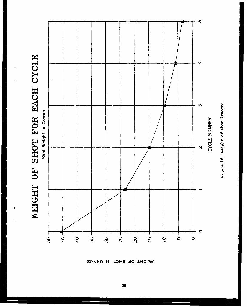
The contaminated media was then cycled through five complete blasting and recovery cycles. Theamount of steel shot captured by the magnetic separator was weighed after each cycle. Table 1shows the amount of shot removed after each cycle.
33
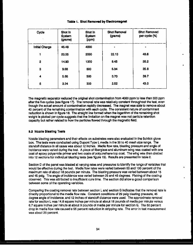
Table 1. Shot Removed by Electromagnet
Cycle Shot In Shot In Shot Removal Shot RemovedSystem System (grams) per cycle (%)(grams) (ppm)
Initial Charge 45.48 4000
1 23.35 2000 22.13 48.6
2 14.90 1300 8.45 36,2
3 9.56 800 5.34 35.8
4 5.86 500 3.70 38.7
5 3.34 300 2.52 43.0
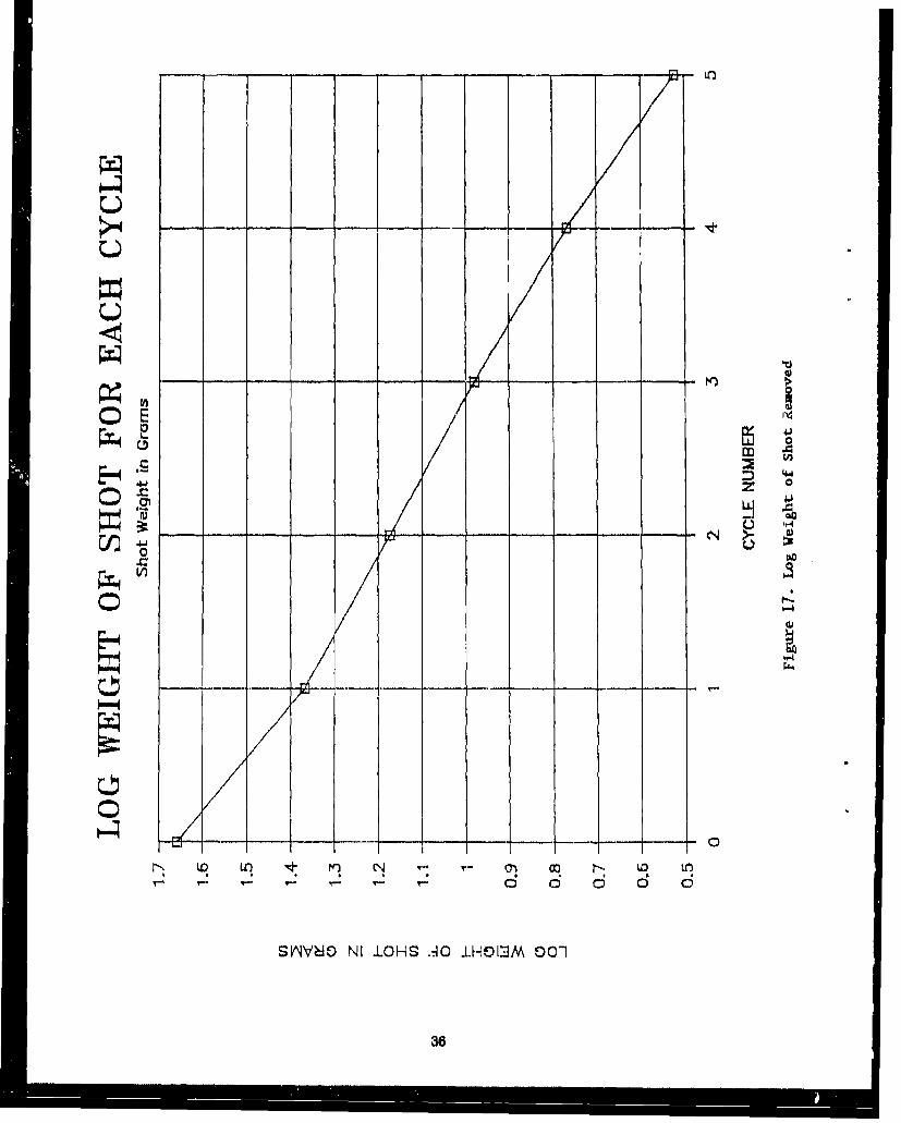
The magnetic separator reduced the original shot contamination from 4000 ppm to less than 300 ppmafter the five cycles (see figure 17). The removal rate was relatively constant throughout the test, eventhough the actual amount of contamination rapidly decreased. The magnet was able to remove about40 percent of the remaining contamination with each cycle. The consistent nature of contaminantreduction Is shown In figure 18. The straight line formed when the logarithm of the remaining shotweight Is plotted per cycle suggests that the limitation on the magnet was not particle retentioncapacity but rather related to how the particles flowed through the magnetic field,
9.2 Nozzle Blasting Teats
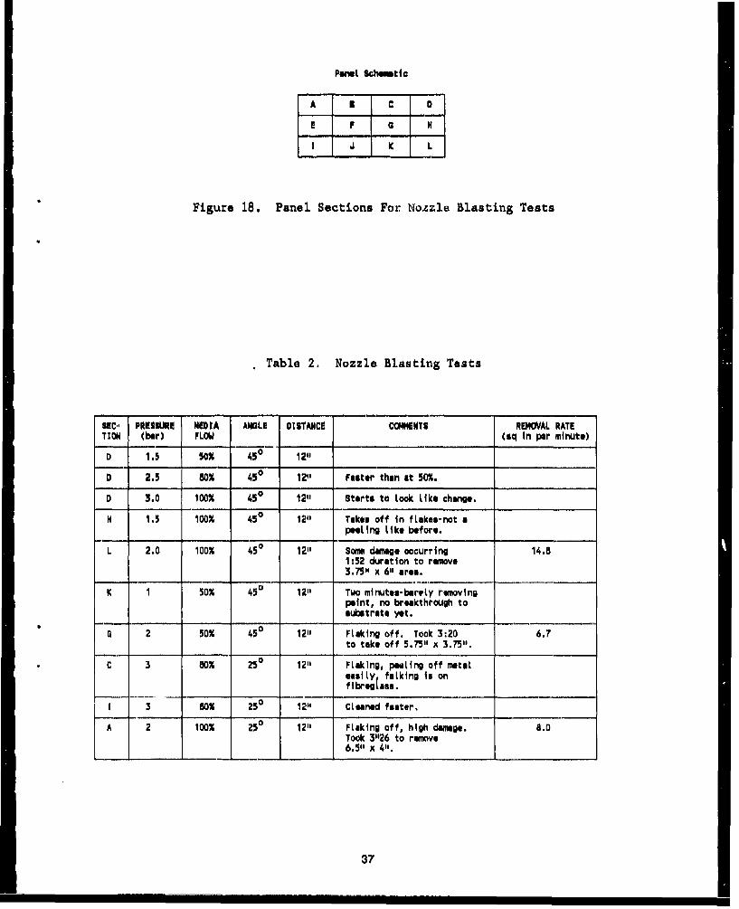
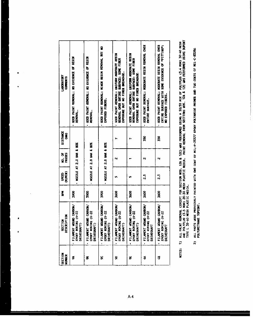
Nozzle blasting parameters and their effects on substrates were also evaluated In the Schlick glovebox, The tests were conducted using Dupont Type L media in the 30 to 40 mesh size range. Thestandoff distance in all cases was about 12 inches. Media flow rate, blasting pressure and angle ofincidence were varied during the test. A piece of fiberglass and aluminum wing was coated with onecoat of epoxy polyamide primer and two coats of polyurethane top coat. The wing was then dividedinto 12 sections for Individual blasting tests (see figure 19). Results are presented In table 2,
Section D of the panel was blasted at varying rates and pressures to Identify the range of variables thatwould be effective during the test. Media flow rates were varied between 50 and 100 percent of themaximum rate of about 18 pounds per minute. The blasting pressure was varied between about 15and 45 pslg. The angle of incidence was varied between 25 and 45 degrees. Flaking of the coatingobserved. This was attributed to Insufficient cure time, The section did allow a good comparisonbetween some of the operating variables,
Comparing the coating removal rate between section L and section G indicates that the removal rate isdirectly proportional to the media flow rate. Constant conditions of 29 psig blasting pressure, 45degree angle of incidence, and 12 Inches of standoff distance were used, The approximate removalrate for section L was 14.8 square inches per minute at about 18 pounds of media per minute versus6.7 square Inches per minute at about 9 pounds of media per minute for section G. The 50 percentdrop In media flow rate caused a 55 percent reduction in stripping rate. The error in test measurementwas about 20 percent.
34
-U-W
0 ~
0 . L n O 0 iLO I t N4q -2
SýNVýO NIIOHS40 I0130
310
;70
0.
r44
2:0
-U 4.
;T
cu
SkNVMA N I LOHS -AO i.Hc)IMM 00-1
Poane Schoovmtic
A B C D
E F a H
S J K L
Figure 18. Panel Sections For Nozzle Blasting Tests
Table 2. Nozzle Blasting Tests
SC', PRESSURE MEDIA ANGLE DISTANCE COM4ENTS REMOVAL RATE
TION (bar) FLOW (sq In per minute)
D 1.5 50M 450 12"
D 2.5 80% 450 12" Faster than at 50%.
D 3.0 100% 450 12" Starts to Look Like change.
H 1.5 100% 450 12" Takes off in fLakes-not apeeeing Like before.
L 2.0 100% 450 12" Some damage occurring 14.81:52 duration to remove3.751 x 61, area.
K I 50% 45 u 12" Two minutes-barely removingpaint, no breakthrough tosubstrate yet.
G 2 50% 450 12" FLaking off. Took 3:20 6.7to take off 5.75"1 x 3.75".
C 3 80% 250 12" FLaking, petLting off metaLesiLty faLking is onflbregIasa.
1 3 80% 250 12" CLeanred feater,
A 2 100% 25:0 12" Flaking off, high damage. 8.0Took 3"26 to remove6.5" x 4".
37
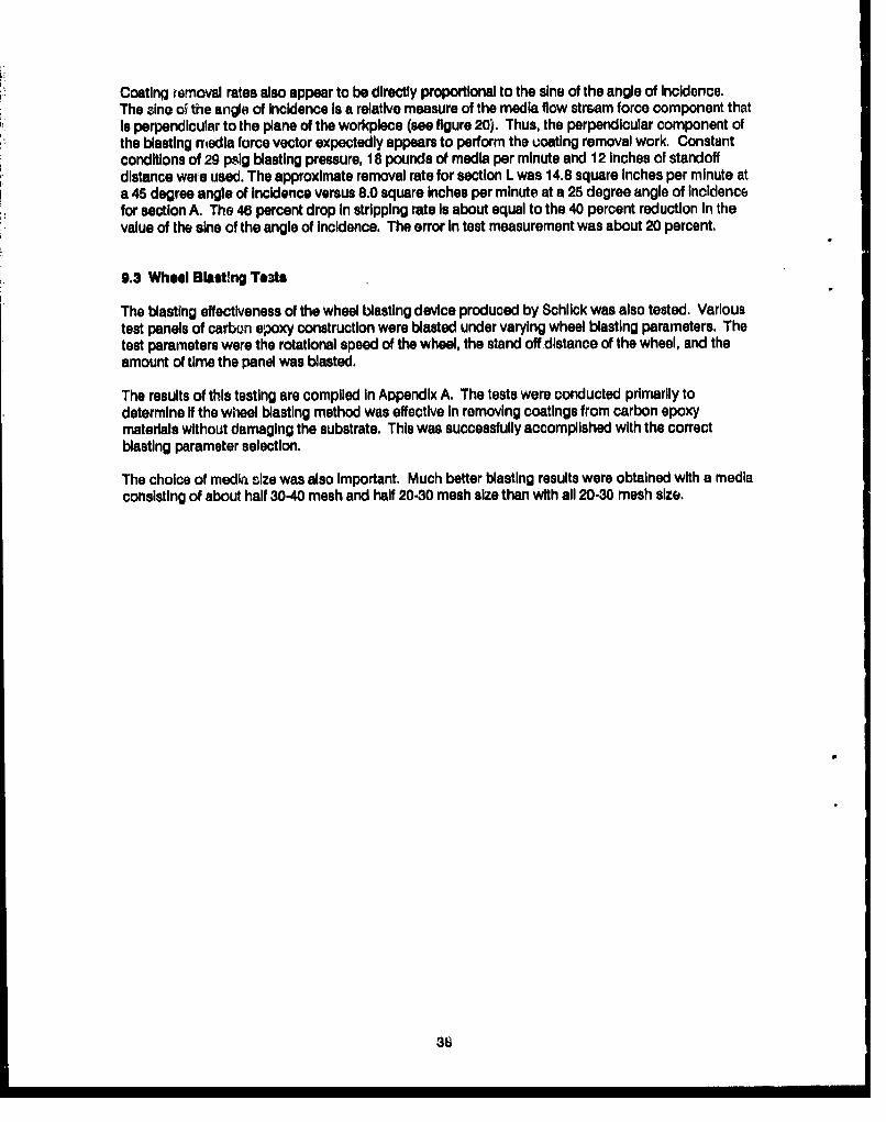
Coating removal rates also appear to be directly proportional to the sine of the angle of Incidence,The sine o5 the angle of Incidence Is a relative measure of the media flow stream force component thatIs perpendicular to the plane of the workplece (see figure 20). Thus, the perpendicular component ofthe blasting rmtedia force vector expectedly appears to perform the coating removal work. Constantconditions of 29 pslg blasting pressure, 18 pounds of media per minute and 12 Inches of standoffdistance were used. The approximate removal rate for section L was 14.8 square Inches per minute ata 45 degree angle of Incidence versus 8.0 square inches per minute at a 25 degree angle of Incidencefor section A. The 46 percent drop In stripping rate Is about equal to the 40 percent reduction In thevalue of the sine of the angle of Incidence. The error In test measurement was about 20 percent.
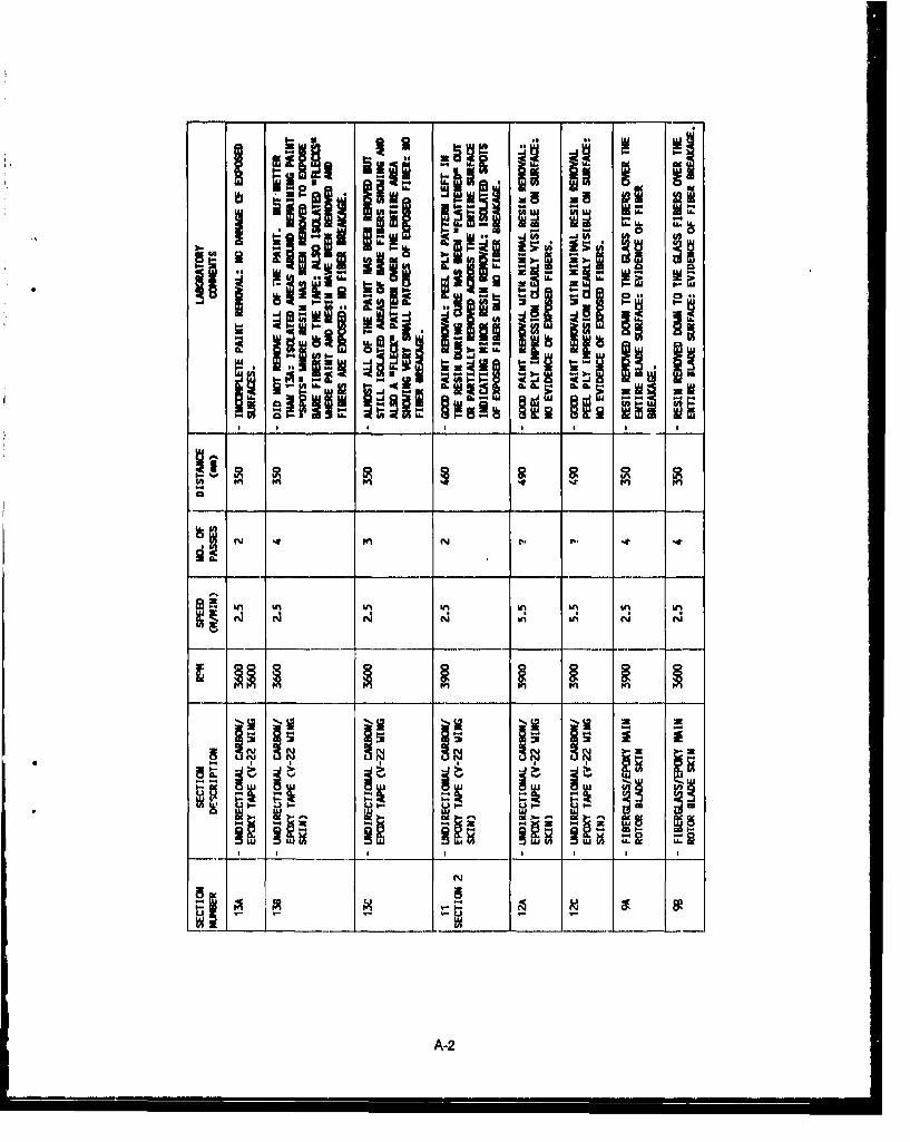
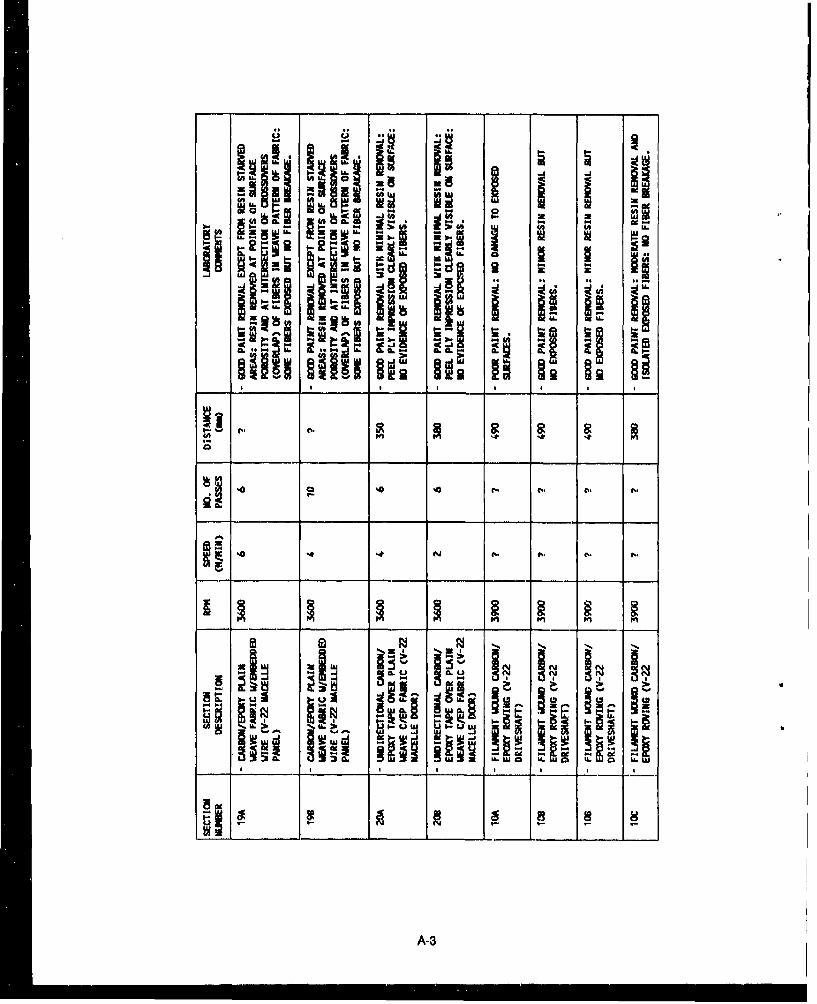
9.3 Wheel Blest~ng Tests
The blasting effectiveness of the wheel blasting device produced by Schlick was also tested. Varioustest panels of carbon epoxy construction were blasted under varying wheel blasting parameters. Thetest parameters were the rotational speed of the wheel, the stand off distance of the wheel, and theamount of time the panel was blasted.
The results of this testing are compiled in Appendix A. The tests were conducted primarily todetermine If the wheel blasting method was effective In removing coatings from carbon epoxymaterials without damaging the substrate. This was successfully accomplished with the correctblasting parameter selection.
The choice of medira size was also Important. Much better blasting results were obtained with a mediaconsisting of about half 30-40 mesh and half 20-30 mesh size than with all 20-30 mesh size.
38
1.ww
6-4 z= I-
-A'-
CIO CL
m *-a
0 0-
CIE-
I-4c4
w -U
LaJ.
2 .. 0 io
IC6 ww2
w 310wU
-U-
-OI- UO-.
(CI-- =
39u -
APPENDIX A
WHEEL BLASTING TESTS
M
0 1
M. .
&n In LM La ka an
ri r 4( aW
ýp 5 2t -5 -5 2 0
Hf H; HA 91; -1;91 -'
raA-2
U U 0
wI 0 L lg
A -3a
aw a
.-In
a I_ N _ - rY N
z a.
U.') U )S
559 0a U. a 0 da L
A-4
DISTRIBUTION LIST
AF 438 ABGft)EE (Wil-tn) McGuire AFB, NJ-. 6550 ABG/DER, Patrick AFB. FL; AFIT/DET (Hudson).Wright-Pattcrson Ai-13, OH; AFITIDET, Wright-Patterson APR. OI-,; CSR 42Wn (K. Davidson). PatrickAFB, FL; Capt Holland, Smodia Arabia;, MO ANG. 231 CEP/DED (Schmedake). B~ridgetoni, MO
AF HQ ESD/DEE, Hanscom AFB. MAAFB 42 CPS/Ready Offr, Loring AFB, ME; AUL/LSE 63-465. Maxwell AF1B. AL; HO MAC/DEEE, Scott
AFB, IL; HQ TAC/DEMM (Pollard), Langley AFB, VAAFESC DEB, Tyndall AFT. FL; TIC (library), Tyndall AFB, ElAFSC DEEQ (P. Montoy&), Peterson AFB. COARMY 416th ENCOM, Akion Survey Tm, Akron, OH; Cr2COM R&D Tech Lib, Pt Monmouth, Ni;
CEHSC.FU-N (Krajewski), Ft Belvoir, VA; Cl: of Engrs, DAEN-CWE-M. Washington. DC; Ch of Engrs,DAEN-MPU, Washington, DC; Engr Cen, ATSE-DAC-LC, Ft Leonard Wood. MO, HHC, 7th ATC(Rosa), Grafenwohr, GE; NOQ Europe Cmd. AEAEN-PE-U, Heidelberg, GE, HODA (DAEN-ZCM),Washington, DC; Kwajalein Atoll, BMDSC-RKL-C. Marshall Is; POJED-O. Okina~wa. Japan
ARMY BELVOIR R&D CEN STRBE.AALO. Ft Belvoir, VA; STRBE-BLORE, Ft Belvoir. VAARMY CERL CERL-EN, Champaign, IL; Library, Champaign, ILARMY CRREL A. Iskandar, Hanover, NH; Library, Hanover. NHARMY DEPOT Letterkenny, SDSLE-EF, Chambersburg, PA. Letterkenny. SDSLE-SF. Chambersburg, PAARMY EHA Dir, Env Qual, Aberdeen Proving Grad. MD; HSE-RP.HG. Arberdeen Proving Grnd, MD;
HSHB-EA-S, Aberdeen Proving Grad. MD; HSHB-EW, Aberdeen Proving Grnd, MD., HSHB.ME-A,Aberdeen Proving Grnd, MD
ARMY ENGR DIST LMVCO.A/Bentley, Vicksburg. MS. Library, Portland. OR; Library, Seattle, WAARMY ENGR DIV ED-SY (Loyd), Huntsville, AL; HNDED-SY, Huntsville, AL; New England, NEDED-D,
Waltham, MAARMY EWES OF-EC (Webster), Viesburg, MS; Library, Vicksb~ing MS: WESGP-E, Vicksburg, MS;
WESGP.EM (0i Smith), Vicksburg, MSARMY LMC Fort Lee, VAARMY MMRC DRXMR-SM (Lenoe), Watertown, MAARMY MTMC N(TT-CE, Newport News, VACBC Code 10. LDavisville, RI; Code 15, Port Hueneme, CA;, Code 430. Gulfport, MS., Code 470.2, Gulfport.
MS; Libraty, Davisville, RI; PWO (Code 400), Gulfport, MS, PWO (Code 80), Port H~ueneme, CA; PWO,Davisville, RI;, Tech Library, Gulfport, MS
CBUJ 401 OIC, Great Lakes, IL; 405, OIC, San Diego, CA; 411, OIC, Norfolk, VA; 417, QIC, Oak Harbor,WA
CG FMF Lant, SCE, Norfolk, VA; Pace, SCIAD (G5) Camp HM Smith, HICHINFO 01-50D (Cronk), Washington, DCCINCLANTFLT CE Supp Plans Offr, Norfolk, VACINCUSNAVEUR London, UKCNA Tech Library, Alexandria, VACNO DCNO, Logs, OP-452, Washington, DCCOMDT COGARD, Library, Washington, DCCOMPAIR Med, SCE, Naples, ItalyCOMPLEACT PWO. Kadena, Japan; SCE, Yokosuka,, JapanCOMNAVAIRSYSCOM AIR-714, Washington, DC; Code 422, Washington, DCCOMNAVBEACHGRU ONE, CO. San Diego. CACOMNAVMARIANAS Code N4. GuamCOMNAYRESFOR Code 08, New Orleans, LA. Code 823, New Orleans. LACOMNAVSUPPFTORANTARCTICA DET, PWO. Christchurch. NZCOMOCEANSYS Lant, Code N9, Norfolk, VA; Pue, SICE. Pearl 11arbor. HICOMSC Washington. DCCOMSUBLANT Code N404. Norfolk, VACOMTI'.A Lant, SCE, Norfolk. VACOMUSNAV Japan. Code J42EDIRSSP Tech Lib, Washington, DCDODDS Pac, FAC, Okinawa, JapanDOE Wind/Occan Tech Div, Tobacco. MDDTIC Alexandfia, VADTRCEN Code 2834, Annapolis, MD. Code 4111, Bethesda, MD; Code 4120, Annapolis. MD-. Code 42.
Bethesda MD; Code 522. Annapolis. MDEPA-SW Code 101.1, San Diego. CA; Code 114C, San Diego. CAEPA Air Prgm Off, Ann Arbor, Mi. Reg III Lib, Philadelphia. PA,. Reg ViII. Lib, Denver. COFAA Code APM-740 (Tomita), Washington, DCFCTC LANT, PWO, Virginia Bch. VAGIDEP OIC, Corona, CAGSA Code PCDP. Washington, DC
LIBRARY OF CO(NGRESS Sci & 'Tech )Ii, Wwihingtoni. 1)('NMAc l16. CO. Nl(C\S Ta'stin. ('eNI ARCO R IASE C(ode 4IIf'. ('amnp L leone. NC Code 41)(1, C amp xIctij oe. N( : Nfm OunI()l Ir. C amp Plendle will
CA: PAC'. P1WO. Camp Bullter. JA\: PW( . ('tmp ILe jL'ino.. NC': PW( . (Camp Pel'iidlewn1 (Aý Pitl. IE.('amp B~utler, JA
MARINE CORPS I 10 LFL. Washinglim. D('MARITIME ADNIIN NMNIA, Library, King, Point. NYNICAS Code 6EDD. Iwakuni . Japan: Crimilnal Invest D~iv, Kaiteohe. III: PW( ) Ktincohe fil%- Ili-, PW(,
Yumia, AZMICLI3 Cosde B.520. Ba rstow. ('A: PWC (Sachon). B~arstow, (AMC'RD PWO. Stil Diego. CANICRDAC ARC)I('. Ouantico. VA. NI & 1, D~i\ 0mnanco. VA; NSAI' Rep. Qounh11ico. VANAF AROICC'. Mlidwayv Island; Dir, Engrg Div. P1WI). Aisnu .1 Japili: ItW( ). A\Isiul,. .11upanNALF ()IC, Stil Diego, (ANAS Chase FId. C'ode I183(M1. Beeville. TIN; ('use rid. PWO. IiceL'illv TX;. ('odte 111:1". Willow C irive, PA;
Code Ill). Adak. AKý ('ode I3. Alameda~l. 'A: C Ode 163, Keflasik . lehind: ( 'itle 1 83. J(acksonv'ille . Fl.;Code (833. Corpus Christi, TX: C'ode 187. Jaekson'.'ilk, Ff.: C ode 1871111. Ili'agiwiA. NIP: ( 'odle 701.Marietta. CA: ('ode 70,. South We V'1Mua1ii, MiA: ('LIC 8. [PuttI~ei iet . %Il): ( 'ivk 8.%. Iialuxeil River.Nil): File Nlgnit ( )(('. Alameda, C'A: Nleiphik. Dilr. Engrg D i% . NI llin lutin. T N; N Iemlphi. PILYWNlliiigiingo. T~N: Miraimar. (Code 1821 A, Stil D~iego. ('A: Sliruilmri. ItW( . Stin Di )uti. C: NI. ( 'tite 11%3. SunDiego, CA: 0),12-1I. Cltmd A: PW Enogrg (13ramnsii . lat utitl Rise'. NIl): Ill 'W ta lint Dv. New\Orleans, LA. PWO (Code 182) Bermuda; PWO. Aduk. AK; PWO. ('eril Fkied, FL: I-WO. Dallas. TX.PWO. Glenview, iL: PWO. Keflavik. Iceland; PWO. Key West, FL;- PWO, Kingsville Tx: PWO. MolfettField. CA-, PWO. New Orleans. LA; PWO, Sigonella. Itaily; PWO. South Weymouiett NfA: PW(.. WillowGrove. PA: SCE. B~arb~ers Point. HI; SCE. Cubi Point. RP. SCIE, Norlfolk, VA; Whldlicy Is. PW.2. OakHtirbor. WA: Whiting Fid. PWO. Milton, FL
NAVAIRDEVCEN Code 832. Warnminster, PANAVAtRENGCEN Code 182, Lakehurst. NJ; PWO. Lakehurst. NJNAVAIRPROPCEN CO, Trenton, NJ: Code PW-3. Trenton. NJNAVAIRTIESTCEN PWO. Patuxent River. MDNAVAUDSVCI-Q Director. Fulls Church VANAVAVIONICCIEN Code D/701, Indianapolis, IN;, PWO. Indianapolis. INNAVAVNDEPOT Code MINX111. Cherry Point. NC': Code 611. Jucksonville. FL: Code 6163(1, Sun Diego, CA;
Code 640, Pensacola, FL; SCIE. Norfolk, VANAVCAMS MED, SCE, Naples, Italy; PWO. Norfolk, VA; SCE, Wahiawa. HI; West!"ne, SCES, Guam.
Mariana IslundsNAVCI-APGRU Code 50,. Williamsburg, VANAVCOASTSYSCEN Code 230~). Panrnia City. FL; Code 423. Pnainui City. FL; Code 715 0J. Mittleman)
Panama City. FL; PWO (Code 74(l). Panmam Citv. FL: Tech Li hrarv . Panama City. Ft.NAVCOMMSTA Code 4011. Nea Makri. Greeme 1W(., Exiniouth. AusitraliaNAVCONS'rRACEN CO. Port Ilueneniri. ('A: ('oide B-I. Port Illueneic.e ('A; C'ode 'T12. (hill'poit. MVSNAVELEXCEN DET. OIC. Winter Harbor. NIENAVEODi'ECHC(EN 'rech Librar v. Indian Fiend. NIDINAVFAC Centerville Bch, PWO, Ferudale. C'A; N62. Argetain, Nr: I'W() ((odite 511). Hlmkwy \\/,les. UK.
l'WO. Oak Hartbor. WANA VFACENGC3OM C'ode tW . A lexalndrita. VA: Cot de 113. AlmInduttria . V'A: COL iIC 113T' IEssoplultoI. A Ii's udrill
VA: Co de IW. Alexandr1ill. VA. (,tidle 0 4A. Ale sanditia. VA: Coide 14 A I A Ii'sititlri a. VA.\: (ol 0ie14A3.*\Iexndriai. VA: (tiole 014A41;. A\lexanidria. VA.\ (-I oil W 1\1i PII ir~ \Ie\;unt~ria. VA: ('ode 05SIA.Alexundria. VA: Code (0631. AlexAndria. VA: ('ode ((83, Alexandria. VA: ('ode l(9N1 124 I Lib). Alexandria,VA: Code IiM213. Alexandria. VA: Code 163. Alexandrln. VA: ('ode let5 I Alexandria. VA: ('ode I8.Alexandria. VA
NAVFACENGCOMv CHES DIV. FPO-IP1L. Washington. DC'NAVFACENGCOM LAN'r DIV. Blr Ofe. Dir. Naples. Italy: ('ode 1112. Norfolk, VA: ('ode 4013, Norfolk.
VA; Code 40(5. Norfolk. VA: Library. Norfolk. VANAVFACENGCOM - NORTH DIV. CO. Philadelphia. PIA: ('ode ((4. Philudelphiai. PA: (ode (PAL..
Philade.lphia. P'A: C'ode 114 ( Rhoaids) 1. hilade111hlpbi. PA: C ode 2012.1~. Philadelphiia. PA: ('tidle 41 8AF.l'biladelphhiu . PA
N AVFACENGC'c NI - PAC. DIV N. Ciode 0(911, I'eal I tiriirr 111; ('tide 4015. P'earl Ilhirbi r. Ill: (odte 411hi. Pe arlHa rbor. HLI LibrarY, Pearl HIarbor. I-Il
NAVFAC'EN(WjONI - SOUTH1 DIV. ('tde (NA?. luiutleioni. S(C; Code (1525. ( (nirle'.tiiii S( ; ('tidle 3023.('barlestoll. SC'; ('odte 4015, ( 'luriestiol . SC : C ode[ 4116i. ( 'llalrvlesti S( : Liihti's %. i lltnrksitil in.
NAVFA('PNOC'0N - WEST D)IV. 091,~20. Saml Birunoi. CA.': iCiile W1A2.2 Ibl. Sun itirunio. CA N; (iide 0.413. SullItRMin. ('A: ('tIdC 09H.( Sanl 14111i11. ('A: ('title Ill-'. S;Iii 111-1mit. (A: (Cidl: (103. Suit Ilittitti. (A; Coikv 411h.,.(Smtith). Sant Bruno. ('A: (tile4'c (le'tii~ll Salltii liliii. ( A; M il l. NunIl l11rmioi. (N I';1C NV lit ((lie.
titde ('42. Sjt'ierdki~c. \VA: I'ac NWV N ()WI. ( tid. ("t 511 iR'rl.ik'. \\A.
NAVFACENGCOM CONTRACT'S AROICC, Quantico, VA-, Code 4(A), Portsmnouth, VA: Code 923, Everert.WA; DROICC, Lemoore, CA; North Bay. Code 1042.AA, Vallejo, CA-, 01CC NW. Code II4NW.Silverdale, WA-, 01CC, Guam; OICC/ROICC, Norfolk, VA; OICC/ROICC, Virginia Beach, VA; ROICC(Code 495). Portsmouth, VA, ROICC, Corpus Christi,,TX; ROICC, Jacksonville, FL; ROICC, Keflavik.Iceland; ROICC, Point Mugu, CA; ROICC, Twentynine Palms, CA;, SW Pac. 01CC, Manila, RP;, Trident,01CC, St Marys, GA
NAVFUEL DIET OIC, Yokohama, JapanNAVHOSP CO, Millington, TN; Hd, Fac Mgmt, Camp Pendleton. CA-. SCE (Knapowski), Great Lakes, IL.
SCE, Guam, Mariana Islandls; SCE, Yokosuka, JapanNAVMAG SCE, Subic Bay, RPNAVMARCORESCEN LTJG Davis, Raleigh, NCNAVMEDCLINIC Head, Indust IkIygiene Div, Pearl Harbor, HINAVMEDCOM NWREG, Head, Fac Mgmt Dept, Oakland, CA; SCE, Jacksonville, FL; SWREG, SCE, San
Diego', CANAVMEDRSCHINSTITUTE Code 47, Bethesda, MDNAVOCEANCOMCEN Code EES, Guam, Mariana IslandsNAVOCEANO Library, Bay St Loulc, MSNAVOCISANSYSCEN Code 1514, San Diego, CANAVORDSTA Code 092B1, Indian Head, MD; PWO, Louisville, KYNAVPETRES Director, Washington DCNAYPOSCOL Code 61WL (0, Wilson), Monterey. CA; E. Thornton, Monterey, CANAVPH-IBASE PWO, Norfolk, VA; SCE, San Diego, CANAVSCOLCECOFF Code C35, Port Hueneme, CANAVSEASYSCOM Code PM8296L22 (J Rekas), Washington, DCNAVSECGRU Code 043, Washington, DCNAVSECGRUACI' PWO (Code 40), Edzeil, Scotland;'PWO, Adak, AK; PWO, Sabana Seca, PRNAVSECSTA Code 60, Washington, DC; Code N70, Washington, DCNAVSHIPRSPFAC SCE, Subic Bay, RP,, SCE, Yokosuka, JapanNAVSHIPYD Code 201.5- (Library), Bremerton, WA; Code 420, Long Beach, CA;, Code 443, Bremerton, WA;
Library, Portamouth, NH; Mare Island, PWO, Vallrjo, CA-, Norfolk, Code 380, Portsmouth, VA; Norfolk,Code 411, Portsmouth, VA;, Norfolk, Code 440), Portsmouth, VA. Norfolk, Code 450-HD, Portsmouth, VA,Norfolk, Code 457L, Portsmouth, VA-, PWO (Code 40)0), Long Beuch. CA; PWO. Bremerton, WA; PWO,
Charleston, SCNAVSTA A. Sugihara. Pearl Harbor, HI; CO, Brooklyn, NY,. CO. Long Beach, CA; CO, Roosevelt Roads,
PR; Code 4216, Mayport, FL-, Code 423, FPSO Guantanamo Bay. Dir, Engr Div, PWD, Guantanamo Bay,Cuba; Engrg Dir, PWD, Rota, Spain; PWO, Mayport, FL; SCE, San Diego, CA
NAVSUPPACT PWO, Holy Loch, UK; PWO, Naples, ItalyNAVSUPPFAC Contract Admin Tech Library, Diego GarciaNAVSUPPO Sec Offr, La Maddalens, ItalyNAVSUPSYSCOM Code 0622, Washington, DCNAVSWC Code E211 (Miller), Dahlgren, VA; Code W42 (GD Haga). Dahlgren. VA; DE'r. White Oak Lab,
Code W10 (Okonski) Silver Spring, MD; PWO, Dahigren, VANAVTECHflRACEN SCE, Pensacola FLNAVUSEAWARENOSTA Code 073, Keyport, WANAVWARCOL Code 24, Newport, RINAVWPNCEN AROICCI Chtina Lake, CA; Code 24, China Lake, CA; Code 2637, China Lake, CA; PWO
(Coda~ 266), China Lake, CANAVWPNQSTA Code 093, Yorktown, VA; Dir, Mvaint Control, PWD, Concord, CA: Earle, Code 092. Colts
Neck, NJ; Earle, PWO (Code 09B), Colts N~ck, NJ-. PWO, Charleston, SC; PWO, Seal Beach, CA; PWO.Yorktown. VA
NAVWPNSUPPCEN PWO, Crane, INNETC Code 42, Newport, RI; PWO, Newport, RINCR 20. CONMCD 3, Ops Offr; 40, CO; 5, Ops Dept; 62, Engrg OffrNOAA Dir, Pac Marine Cen, Seattle, WA; Library, Rockville, MDNORDA Code 410, Bay St. Louis, MSNRL Code 2530.1, Washington. DCNSC Cheatham Annex, PWO, Williamsburg. VA;, Code 02, Pearl Harbor. HI:I Code 43, Oakland. CA; Code
54,1. Norfolk, VA; Code 700, Norfolk, VA; SCE. Charleston, SC; SCE, Norrolk, VANSD SCE, Subic Bay, RPOCNR NRL (Ptout), Alexandria, VAOFFICE OF SECRETARY OF DEFENSE OASD, (P&L)IE (Win H. Parker), Washing~on, DC- OIDDR&E.
Environ & Life Sci, Washington, DCPACMISRANFAC HII Area, PWO, Kekaha, HIPHIBCB 1, CO. San Diego, CA; 1, P&E, San Diego, CA; 2, CO, Norfolk, VAPMTC Code 5041, Point Mugu, CA
PWC ACE Office, Norfolk. VA-. Code I0. Great Lakes. IL: C'ode 10). Oukland. CA: Code 1(111 (Library).Oakland. CA; Code 10)11. Pearl Harbor, HI: Code 10113. Osikland. CA: Code 1112. Oaklarnd. CA: (Code123-C, San Diego. CA- Code 30), Norfolk. VA: Code 3t)V, Norfolk. VA,. Code 41141, Great Lakes. IL: Code4WK, Guam. Mariana Islands: Code 4WK. Pearl H-arbor. HI: COLIC 4M,) San Diego. CA: Code 412. San Diego.CA: Code 420). Great Lakes, IL, Code 42)). Oakland. CA: Code 4201) (Witid). Suabic Boy. RP: Code 421(Kavu). Pearl Harbor. Hit Code 421 (Quin). San Diego. CA,. Code 421 (Reynolds). San Diego. CA: Code422. San Diego. CA-. Code 423. San Diego. CA: Code 424. Norfolk. VA: (Code 430(1 Kyl). Pearl Harhor. HI
PWC Code 430) (Kyil. Pearl I-larbor, HIPWC Code 50. Pensacola. FL. Code 5WK, Great Lakes. IL. Code 5114), Norfolk, VA,. Code 5WK. Oakland. CA:
Code 541), Sun Diego. CA: Code Nil). Great Lakes. IL: Code 612. Pearl Harbor. HI: Code 614. San Diego.CA: Code 615. Guam. Mariana Islands; Code 7111), Great Lakes, IL; Code 7M.) Norfolk. VA. Code 7W.) San.Diego. CA-. Library (Code 134), Pearl- Harbor. HI: Library. Guam. Mariana Islands; Library. Norfolk. VA:Library. Pensacola. FL. Library. Yokosukii. Japan. Tech Library, Subic Bay, RP: UtIM Dept (R Pascua).Pearl Harbor, HI
SUPSHIP Tech Library. Newport News, VAUCT TWO. CO, Port Hueneme. CAUS DEPT OF INTERIOR BLM. Engrg Div (730l). Washington, DC-, Natl Park Svc, RMR/PC. Denver, COUS GEOLOGICAL SURVEY J Bales, Raleigh, NCUSCINCPAC Code J44. Camip HIM Smith, HIUSDA Ext Sen' (T Maher), Washington. DC,, For Svc Reg 8, (Bowers). Atlanta. GA-: For Svc, Equip Dev
Cen, San Dimas, CA-, For Svc, Tech Engrs. Washington. DCUSNA Mech Engrg Dept (Power), Annapolis. MD. PWO, Annapolis. MD; Sys Engrg (Tuttle), Annapolis. MDUSS USS JASON. Rpr OffrARIZONA STATE UNIVERSITY Design Sci (Kroolinger), Tempe. AZBROOKHAVEN NATL LAB M. Steinberg, Upton, NYCALIFORNIA Nay & Ocean Dev (Armstrong). Sacramento. CACITY OF LIVERMORE Dackins, PE. Livermore. CACLEMSON UNIVERSITY Arch Col (Egan), Clemson, SCCLEVELAND STATE UNIVERSITY CE Dept (Akinmusuru). Cleveland, OHCORNELL UNIVERSITY Library. Ithaca, NYDAMES & MOORE Library. Los Angeles, CAFLORIDA INST OF TECH CE Dept (Kalajian), Melbourne, FLFOREST INST FOR OCEAN & MT Library. Carson City, NVINSTITUTE OF MARINE SCIENCES Library, Port Aransas, TXIOWA STATE UNIVERSITY Arch Dept (McKrown), Ames, IA:. CE Dept (Handy), Ames. IAKEENE STATE COLLEGE Sdi Dept (Cunningham), Keene. NHLAWRENCE LIVERMORE NATL LAB FJ Tokurz, Livermore. CA: Plant Engrg Lib, (L-654), Livermore, CALEHIGH UNIVERSITY Linderman Library, Bethlehem, PALONG BEACH PORT Engrg Dir (Allen). Long Beach. CALOS ANGELES COUNTY PW Dept (J Vicelju), Alhambra, CAMICHIGAN TECH UNIVERSITY CE Dept (Haus), Houghton, MIMISSOURI Nat Res Dept. Energy Div, Jefferson City, MOMIT Engrg Lib, Cambridge, MA-. Lib, Tech Ranorts. Cambridge. MA:. RV Whitman. Cambridge, MANATL ACADEMY OF SCIENCES NRC. Dr. Chung, Washington. DC; NRC. Naval Studies Bd. Washington.
DCNEW MEXICO SOLAR ENERGY INST Dr. Zwibel, Las Cruces. NMNEW YORK Energy Office, Lib, Albany. NYNEW YORK STATE MARITIME COLLEGE Longohardi. Bronx, NYNY CITY COMMUNITY COLLEGE Library. Brooklyn, NYOREGON STATE UNIVERSITY CE Dept (Hicks), Corvallis, ORPENNSYLVANIA STrATE UNIVERSITY Applied Rsch Lab, State College. PAPURDUE UNIVERSITY Engrg Lib. W, Lafayette. INSEATITLE PORT W Ritchie, Seattle, WASOUTHWEST RSCH INST Energetic Sys Dept (Esparza). San Antonio. TX; M. Polcyn. San Antonio, TXSTATE UNIVERSITY OF NEW YORK CE Dept (Reinhorit). Buffalo, NY: CE Dept. Buffalo. NYTECH UTILIZATION K Willinger. Washington. DCTEXAS A&I UNIVERSITY Civil & Mech Engr Dept (Parate), Kingsville, TXTEXAS A&M UNIVERSITY CE Dept (Machemehl), College Station. TXUNIV OF TENNESSEE CC Dept (KanL). K(noxville, TrNUNIVERSITY OF ALABAMA Dir Fite Mgmt (Baker). Birmingham., ALUNIVERSITY OF CALIFORNIA CE Dept (Mitchell), Berkeley. CAUNIVERSITY OF H-ARTFORD CE Dep~t (Keshawarz). West Hartford, CTUNIVERsITY OF HAWAII M1anoa, Library. Honolulu, HI1UNIVERSITY OF ILLINOIS Library. Urbana., IL: Metz Re) Rmi. Urtbana. ILUNIVERSITY OF MICHIGAN CE Dept (Riehart). Ann Arbor, MIUNIVERSITY OF NEBRASKA Polar Iee (2oriny. Office. Liocolo. NE
"UNIVERSITY OF NEW MEXICO NMERI (Falk). Albuquerque NM: NMERI (Leigh). Albuquerque. NM:NMERI (Tapscott). Albuquerque. NM
UNIVERSITY OF TEXAS CE Dept (Thompson). Austin. TX: Construction Industry Inst. Austin, TXUNIVERSITY OF WASHINGTON Engrg Col (Carlson). Seattle. WA: RL Tcrrel, Edmonds, WAUNIVERSITY OF WISCONSIN Great Lakes Studies Cen. Milwaukee. WIVENTURA COUNTY Deputy PW Dir. Verntura. CA, PWA (Brownie). Ventura, CAWORCESTER POLYTECH INST Mech Engrg Dept (Sullivan). Worcester. MAADVANCED TECHNOLOGY. INC Ops Cen Mgr (Bednar), Camarillo. CAAPPLIED SYSTEMS R. Smith. Agana. GuamARCAIR CO D. Young, Lancaster. OHARVID GRANT & ASSOC Olympia. WABATrELLE New Eng Marine Rsch Lab, Lib. Duxbury. MABECHTEL CIVIL, INC Woolston, San Francisco. CABRITISH EMBASSY Sci & Tech Dept (Wilkins), Washington. DCBROWN & ROOT Ward, Houston, TXCORRIGAN, LCDR S. USN. CEC. Stanford. CACLARENCE R JONES, CONSULTN, LTD Augusta. GACOLLINS ENGRG, INC M Garlich, Chicago. ILCONSOER TOWNSEND & ASSOC Schramm. Chicago. ILCONSTRUCTION TECH LABS. INC AE Fiorato. Skokie. ILDILLINGHAM CONSTR CORP (HD&C). F McHale. Honolulu, HIDURLACH, O'NEAL. JENKINS & ASSOC Columbia. SCDYNAMAC CORP HMTC-C, Rockville. MDGARD INC LB Holmes, Niles, ILGDM & ASSOC. INC Fairbanks. AKGRUMMAN AEROSPACE CORP Tech Info Ctr. Bethpage. NYHALEY & ALDRICH, INC. TC. Dunn. Cambridge. MAHAYNES & ASSOC H. Haynes. PE. Oakland, CAHIRSCH & CO L Hirsch, San Diego, CAIRE-ITrD Input Proc Dir (R. Danford). Eagan, MNJOHN J MC MULLEN ASSOC Library. New York, NYKATSURA CONSULTING ENGRS Y, Katsura. Ventura, CALEONARD STOLBA, AIA P. Brinckerhoff, Sacramento. CALINDA HALL LIBRARY Doe Dept. Kansas City. MOMATRECON, INC H. Haxo. Alameda. CAMC CLELLAND ENGRS. INC Library, Houston. TXMOFFATT & NICHOL ENGRS R Palmer, Long Beach, CAEDWARD K NODA & ASSOC Honolulu. HINUHN & ASSOC A.C. Nuhn. Wayzata, NMPACIFIC MARINE TECH (M. Wagner) Duvall, WAPRESNELL ASSOC. INC DG Ptesnell, Jr. Louisville, KYSANDIA LABS Library. Livermore, CASAUDI ARABIA king Saud Univ. Rsch Cet, RiyadhSCIENCE APPS INTL CORP. Alexandria. VASHANNON & WILSON, INC Librarian, Seattle. WASRI INTL J.L. Jones, Chem Engr Lab, Menlo Park. CATREMCO, INC M Raymond. Cleveland, OHTRW INC Crawford, Redondo Beach, CA; Engr Library, Cleveland. OH: Rodgers, Redondo Beach, CAUNITED TECHNOLOGIES Hamilton Std Div. Lib, Windsor Locks, CTWISS, JANNEY. ELSTNER. & ASSOC DW Pfeifer. Northbrook, ILWOODWARD-CLYDE CONSULTANTS R. Cross, Oakland. CA; West Reg, Lib. Oakland, CABULLOCK. TE La Canada, CAFOWLER, J.W. Virginia Beach. VAHANDLEY, DM Gulf Breeze. FLHARDY. S.P. San Ramon. CANEASE. A.D,, JR Panama City. FLPADILLA, LM Oxnard, CAPAULI. DC Silver-Spring. MDPETERSEN, CAPT N.W. Pleasanton. CAPODELL, H.I. New Rochelle. NYQUIRK. J Panama City. FLSPIELVOGEL. L Wyncote. PASTEVENS. TW Dayton, OHTAMPA PORT AUTHORITY Engrg Dept (Schrader), Tampa, FLULASZEWSKI, CDR T.J. Honolulu, HIVAN ALLEN. B Kingston, NY