Embed Size (px)
Citation preview
AboveAir™ MissionCritical™ A/C’sAboveAir Technologies (MC22-L10)1
AboAboAboAboAbovvvvveAireAireAireAireAir™ floor mounted precision air conditioners (MC22-L10)
Engineering Manual
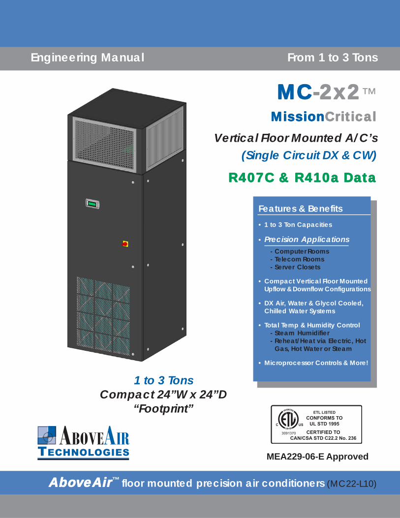
1 to 3 TonsCompact 24”W x 24”D
“Footprint”
Features & Benefits• 1 to 3 Ton Capacities
• Precision Applications- Computer Rooms- Telecom Rooms- Server Closets
• Compact Vertical Floor MountedUpflow & Downflow Configurations
• DX Air, Water & Glycol Cooled,Chilled Water Systems
• Total Temp & Humidity Control- Steam Humidifier- Reheat/Heat via Electric, Hot
Gas, Hot Water or Steam
• Microprocessor Controls & More!
From 1 to 3 Tons
R407C & R410a DaR407C & R410a DaR407C & R410a DaR407C & R410a DaR407C & R410a Datatatatata
MCMCMCMCMC-2x2-2x2-2x2-2x2-2x2™MissionMissionMissionMissionMissionCriticalCriticalCriticalCriticalCritical
Vertical Floor Mounted A/C’s(Single Circuit DX & CW)
MEA229-06-E Approved

AboveAir™ MissionCritical™ A/C’s AboveAir Technologies (MC22-L10)2 Introduction
INTRODUCTION
AboAboAboAboAbovvvvveeeeeAirAirAirAirAir™™™™™ MissionCritical™vertical floor mounted precisionair conditioners are the reliableenvironmental control solution toyour precision cooling needs.Available in a wide variety ofcooling methods and cabinetconfigurations including a fullrange of options, AboAboAboAboAbovvvvveeeeeAirAirAirAirAir™™™™™
Air Conditioners are a stepabove!
R407c or Optional R410a Refrigerant 100% Front-Access cabinet design Total Temperature & Humidity Control Up-Flow & Down-Flow air patterns Variety of cooling methods Self-contained & split systems Flexible options and accessories Energy efficient operation
ContentsIntroduction ................................................ 2
Model Configurations ........................ 2 & 17
Features and Benefits ............................... 3
Performance Data ................................... 4-8
Electrical Data ....................................... 9-11
Guide Specifications .......................... 12-16
Dimensional Data ................................ 18-21
Approximate Unit Weights (lbs) .............. 23
VCH & XPU-( )DX - Air Cooled Split with Propeller Fan, Outdoor Remote Condensing Unit
VCE & XP1-( )DX - Air Cooled Split with Propeller Fan, Outdoor Remote Condenser
VCW & VCG-( )DX - Water/Glycol Cooled Self-Contained Plus Glycol Drycoolers &Pump Packages
VCC-( )Chilled Water Air Handling Units
DX - Air Cooled
DX - Water/Glycol Cooled
Chilled Water Systems
VCH/E & CCU/CCX & XCU/XCX -( )DX - Air Cooled Split with Centrifugal Blower, indoor RemoteCondensing Unit & Condensers
FC_ & PA_ ModelsRemote Indoor & Outdoor
Glycol Drycoolers andPump Packages
AboveAir™ MissionCritical™ A/C’sAboveAir Technologies (MC22-L10)3Features & Benefits
FEATURES & BENEFITS
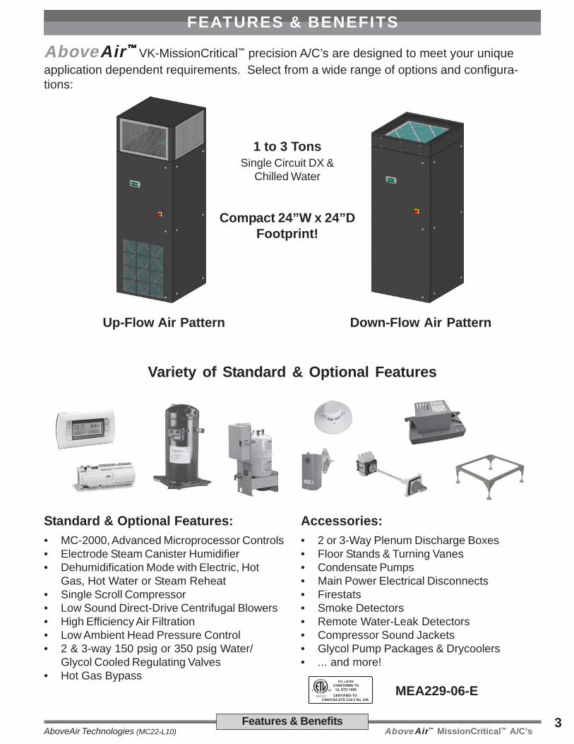
AboveAir™™™™™ VK-MissionCritical™ precision A/C’s are designed to meet your uniqueapplication dependent requirements. Select from a wide range of options and configura-tions:
Standard & Optional Features:• MC-2000, Advanced Microprocessor Controls• Electrode Steam Canister Humidifier• Dehumidification Mode with Electric, Hot
Gas, Hot Water or Steam Reheat• Single Scroll Compressor• Low Sound Direct-Drive Centrifugal Blowers• High Efficiency Air Filtration• Low Ambient Head Pressure Control• 2 & 3-way 150 psig or 350 psig Water/
Glycol Cooled Regulating Valves• Hot Gas Bypass
Variety of Standard & Optional Features
Accessories:• 2 or 3-Way Plenum Discharge Boxes• Floor Stands & Turning Vanes• Condensate Pumps• Main Power Electrical Disconnects• Firestats• Smoke Detectors• Remote Water-Leak Detectors• Compressor Sound Jackets• Glycol Pump Packages & Drycoolers• ... and more!
1 to 3 TonsSingle Circuit DX &
Chilled Water
Compact 24”W x 24”DFootprint!
MEA229-06-E
Up-Flow Air Pattern Down-Flow Air Pattern
AboveAir™ MissionCritical™ A/C’s AboveAir Technologies (MC22-L10)4 Performance Data
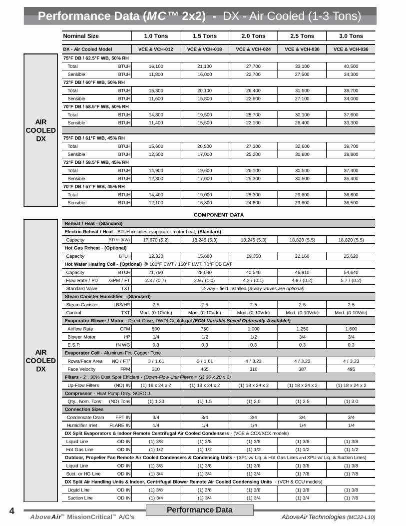
Performance Data (MC™ 2x2) - DX - Air Cooled (1-3 Tons)Nominal Size 1.0 Tons 1.5 Tons 2.0 Tons 2.5 Tons 3.0 Tons
DX - Air Cooled Model VCE & VCH-012 VCE & VCH-018 VCE & VCH-024 VCE & VCH-030 VCE & VCH-036
AIRCOOLED
DX
75°F DB / 62.5°F WB, 50% RH
Total BTUH 16,100 21,100 27,700 33,100 40,500
Sensible BTUH 11,800 16,000 22,700 27,500 34,300
72°F DB / 60°F WB, 50% RH
Total BTUH 15,300 20,100 26,400 31,500 38,700
Sensible BTUH 11,600 15,800 22,500 27,100 34,000
70°F DB / 58.5°F WB, 50% RH
Total BTUH 14,800 19,500 25,700 30,100 37,600
Sensible BTUH 11,400 15,500 22,100 26,400 33,300
75°F DB / 61°F WB, 45% RH
Total BTUH 15,600 20,500 27,300 32,600 39,700
Sensible BTUH 12,500 17,000 25,200 30,800 38,800
72°F DB / 58.5°F WB, 45% RH
Total BTUH 14,900 19,600 26,100 30,500 37,400
Sensible BTUH 12,300 17,000 25,300 30,500 35,400
70°F DB / 57°F WB, 45% RH
Total BTUH 14,400 19,000 25,300 29,600 36,600
Sensible BTUH 12,100 16,800 24,800 29,600 36,500
COMPONENT DATA
AIRCOOLED
DX
Reheat / Heat - (Standard)
Electric Reheat / Heat - BTUH includes evaporator motor heat, (Standard)
Capacity BTUH (KW) 17,670 (5.2) 18,245 (5.3) 18,245 (5.3) 18,820 (5.5) 18,820 (5.5)
Hot Gas Reheat - (Optional)
Capacity BTUH 12,320 15,680 19,350 22,160 25,620
Hot Water Heating Coil - (Optional) @ 180°F EWT / 160°F LWT, 70°F DB EAT
Capacity BTUH 21,760 28,080 40,540 46,910 54,640
Flow Rate / PD GPM / FT 2.3 / (0.7) 2.9 / (1.0) 4.2 / (0.1) 4.9 / (0.2) 5.7 / (0.2)
Standard Valve TXT 2-way - field installed (3-way valves are optional)
Steam Canister Humidifier - (Standard)
Steam Canister LBS/HR 2-5 2-5 2-5 2-5 2-5
Control TXT Mod. (0-10Vdc) Mod. (0-10Vdc) Mod. (0-10Vdc) Mod. (0-10Vdc) Mod. (0-10Vdc)
Evaporator Blower / Motor - Direct-Drive, DWDI Centrifugal (ECM Variable Speed Optionally Available!)
Airflow Rate CFM 500 750 1,000 1,250 1,600
Blower Motor HP 1/4 1/2 1/2 3/4 3/4
E.S.P. IN WG 0.3 0.3 0.3 0.3 0.3
Evaporator Coil - Aluminum Fin, Copper Tube
Rows/Face Area NO / FT2 3 / 1.61 3 / 1.61 4 / 3.23 4 / 3.23 4 / 3.23
Face Velocity FPM 310 465 310 387 495
Filters - 2", 30% Dust Spot Efficient - (Down-Flow Unit Filters = (1) 20 x 20 x 2)
Up-Flow Filters (NO) IN (1) 18 x 24 x 2 (1) 18 x 24 x 2 (1) 18 x 24 x 2 (1) 18 x 24 x 2 (1) 18 x 24 x 2
Compressor - Heat Pump Duty, SCROLL
Qty., Nom. Tons (NO) Tons (1) 1.33 (1) 1.5 (1) 2.0 (1) 2.5 (1) 3.0
Connection Sizes Condensate Drain FPT IN 3/4 3/4 3/4 3/4 3/4
Humidifier Inlet FLARE IN 1/4 1/4 1/4 1/4 1/4
DX Split Evaporators & Indoor Remote Centrifugal Air Cooled Condensers - (VCE & CCX/XCX models)
Liquid Line OD IN (1) 3/8 (1) 3/8 (1) 3/8 (1) 3/8 (1) 3/8
Hot Gas Line OD IN (1) 1/2 (1) 1/2 (1) 1/2 (1) 1/2 (1) 1/2
Outdoor, Propeller Fan Remote Air Cooled Condensers & Condensing Units - (XP1 w/ Liq. & Hot Gas Lines and XPU w/ Liq. & Suction Lines)
Liquid Line OD IN (1) 3/8 (1) 3/8 (1) 3/8 (1) 3/8 (1) 3/8
Suct. or HG Line OD IN (1) 3/4 (1) 3/4 (1) 3/4 (1) 7/8 (1) 7/8
DX Split Air Handling Units & Indoor, Centrifugal Blower Remote Air Cooled Condensing Units - (VCH & CCU models)
Liquid Line OD IN (1) 3/8 (1) 3/8 (1) 3/8 (1) 3/8 (1) 3/8
Suction Line OD IN (1) 3/4 (1) 3/4 (1) 3/4 (1) 3/4 (1) 7/8
AboveAir™ MissionCritical™ A/C’sAboveAir Technologies (MC22-L10)5Performance Data
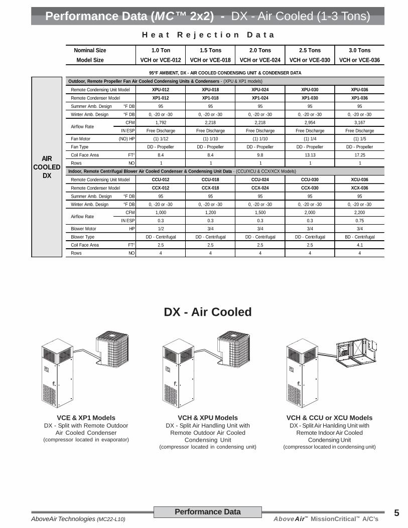
Performance Data (MC™ 2x2) - DX - Air Cooled (1-3 Tons)H e a t R e j e c t i o n D a t a
Nominal Size 1.0 Ton 1.5 Tons 2.0 Tons 2.5 Tons 3.0 TonsModel Size VCH or VCE-012 VCH or VCE-018 VCH or VCE-024 VCH or VCE-030 VCH or VCE-036
95°F AMBIENT, DX - AIR COOLED CONDENSING UNIT & CONDENSER DATA
AIRCOOLED
DX
Outdoor, Remote Propeller Fan Air Cooled Condensing Units & Condensers - (XPU & XP1 models)
Remote Condensing Unit Model XPU-012 XPU-018 XPU-024 XPU-030 XPU-036
Remote Condenser Model XP1-012 XP1-018 XP1-024 XP1-030 XP1-036
Summer Amb. Design °F DB 95 95 95 95 95
Winter Amb. Design °F DB 0, -20 or -30 0, -20 or -30 0, -20 or -30 0, -20 or -30 0, -20 or -30
Airflow RateCFM 1,792 2,218 2,218 2,954 3,167
IN ESP Free Discharge Free Discharge Free Discharge Free Discharge Free Discharge
Fan Motor (NO) HP (1) 1/12 (1) 1/10 (1) 1/10 (1) 1/4 (1) 1/5
Fan Type DD - Propeller DD - Propeller DD - Propeller DD - Propeller DD - Propeller
Coil Face Area FT2 8.4 8.4 9.8 13.13 17.25
Rows NO 1 1 1 1 1
Indoor, Remote Centrifugal Blower Air Cooled Condenser & Condensing Unit Data - (CCU/XCU & CCX/XCX Models)
Remote Condensing Unit Model CCU-012 CCU-018 CCU-024 CCU-030 XCU-036
Remote Condenser Model CCX-012 CCX-018 CCX-024 CCX-030 XCX-036
Summer Amb. Design °F DB 95 95 95 95 95
Winter Amb. Design °F DB 0, -20 or -30 0, -20 or -30 0, -20 or -30 0, -20 or -30 0, -20 or -30
Airflow RateCFM 1,000 1,200 1,500 2,000 2,200
IN ESP 0.3 0.3 0.3 0.3 0.75
Blower Motor HP 1/2 3/4 3/4 3/4 3/4
Blower Type DD - Centrifugal DD - Centrifugal DD - Centrifugal DD - Centrifugal BD - Centrifugal
Coil Face Area FT2 2.5 2.5 2.5 2.5 4.1
Rows NO 4 4 4 4 4
DX - Air Cooled
VCE & XP1 ModelsDX - Split with Remote Outdoor
Air Cooled Condenser(compressor located in evaporator)
VCH & XPU ModelsDX - Split Air Handling Unit with
Remote Outdoor Air CooledCondensing Unit
(compressor located in condensing unit)
VCH & CCU or XCU ModelsDX - Split Air Hanlding Unit with
Remote Indoor Air CooledCondensing Unit
(compressor located in condensing unit)

AboveAir™ MissionCritical™ A/C’s AboveAir Technologies (MC22-L10)6 Performance Data
Performance Data (MC™ 2x2) - DX - Water Cooled (1-3 Tons)Nominal Size 1.0 Tons 1.5 Tons 2.0 Tons 2.5 Tons 3.0 Tons
DX - Water Cooled Model VCW-012 VCW-018 VCW-024 VCW-030 VCW-036
WATERCOOLED
DX
75°F DB / 62.5°F WB, 50% RH
Total BTUH 16,900 22,100 29,100 34,700 42,600
Sensible BTUH 12,200 16,500 23,300 28,000 34,800
72°F DB / 60°F WB, 50% RH
Total BTUH 16,100 21,100 27,700 33,200 40,000
Sensible BTUH 12,000 16,300 22,900 27,700 34,100
70°F DB / 58.5°F WB, 50% RH
Total BTUH 15,600 20,500 27,000 32,300 39,600
Sensible BTUH 11,700 16,000 22,500 27,200 34,000
75°F DB / 61°F WB, 45% RH
Total BTUH 16,400 21,600 28,200 34,200 41,800
Sensible BTUH 12,900 17,600 25,300 31,000 39,000
72°F DB / 58.5°F WB, 45% RH
Total BTUH 15,600 20,500 27,400 32,700 40,000
Sensible BTUH 12,700 17,300 25,400 31,100 39,400
70°F DB / 57°F WB, 45% RH
Total BTUH 15,100 20,000 26,700 31,800 38,900
Sensible BTUH 12,400 17,000 25,100 30,800 38,900
COMPONENT DATA
WATERCOOLED
DX
Reheat / Heat - (Standard)
Electric Reheat / Heat - BTUH includes evaporator motor heat, (Standard)
Capacity BTUH (KW) 17,670 (5.2) 18,245 (5.3) 18,245 (5.3) 18,820 (5.5) 18,820 (5.5)
Hot Gas Reheat - (Optional)
Capacity BTUH 10,300 13,070 22,920 26,240 30,330
Hot Water Heating Coil - (Optional) @ 180°F EWT / 160°F LWT, 70°F DB EAT
Capacity BTUH 21,760 28,080 40,540 46,910 54,640
Flow Rate / PD GPM / FT 2.3 / (0.7) 2.9 / (1.0) 4.2 / (0.1) 4.9 / (0.2) 5.7 / (0.2)
Standard Valve TXT 2-way - field installed (3-way valves are optional)
Steam Canister Humidifier - (Standard)
Steam Canister LBS/HR 2-5 2-5 2-5 2-5 2-5
Control TXT Mod. (0-10Vdc) Mod. (0-10Vdc) Mod. (0-10Vdc) Mod. (0-10Vdc) Mod. (0-10Vdc)
Evaporator Blower / Motor - Direct-Drive, DWDI Centrifugal (ECM Variable Speed Optionally Available!)
Airflow Rate CFM 500 750 1,000 1,250 1,600
Blower Motor HP 1/4 1/2 1/2 3/4 3/4
E.S.P. IN WG 0.3 0.3 0.3 0.3 0.3
Evaporator Coil - Aluminum Fin, Copper Tube
Rows/Face Area NO / FT2 3 / 1.61 3 / 1.61 4 / 3.23 4 / 3.23 4 / 3.23
Face Velocity FPM 310 465 310 387 495
Filters - 2", 30% Dust Spot Efficient
Up-Flow Filters (NO) IN (1) 18 x 24 x 2 (1) 18 x 24 x 2 (1) 18 x 24 x 2 (1) 18 x 24 x 2 (1) 18 x 24 x 2
Down-Flow Filters (NO) IN (1) 20 x 20 x 2 (1) 20 x 20 x 2 (1) 20 x 20 x 2 (1) 20 x 20 x 2 (1) 20 x 20 x 2
Compressor - Heat Pump Duty, SCROLL
Qty., Nom. Tons (NO) Tons (1) 1.33 (1) 1.5 (1) 2.0 (1) 2.5 (1) 3.0
Water Cooled Condenser Data - 85°F EWT / 95°F LWT, 0% Glycol Solution (rated at 75°F DB/62.5°F WB EAT Cooling Performance)
Total Heat of Rej. BTUH 21,470 27,585 35,525 42,635 52,655
Flow 85°F EWT GPM 4.3 5.5 7.1 8.5 10.5
Pressure Drop FT WG 7.8 10.5 12.5 14.5 16.5
Condenser Type Coaxial Coaxial Coaxial Coaxial Coaxial
Water Reg. Valve 2-Way, 150 psig - factory installed, (3-way & High Pressure Valves are Optional)
Connection Sizes Water IN/OUT OD IN 5/8 5/8 5/8 7/8 7/8
Condensate Drain FPT IN 3/4 3/4 3/4 3/4 3/4
Humidifier Inlet FLARE IN 1/4 1/4 1/4 1/4 1/4
AboveAir™ MissionCritical™ A/C’sAboveAir Technologies (MC22-L10)7Performance Data
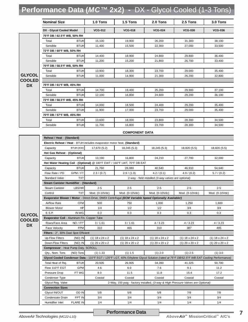
Performance Data (MC™ 2x2) - DX - Glycol Cooled (1-3 Tons)Nominal Size 1.0 Tons 1.5 Tons 2.0 Tons 2.5 Tons 3.0 Tons
DX - Glycol Cooled Model VCG-012 VCG-018 VCG-024 VCG-030 VCG-036
GLYCOLCOOLED
DX
75°F DB / 62.5°F WB, 50% RH
Total BTUH 15,100 19,900 26,200 31,300 38,100
Sensible BTUH 11,400 15,500 22,300 27,000 33,500
72°F DB / 60°F WB, 50% RH
Total BTUH 14,400 18,900 24,800 29,800 36,400
Sensible BTUH 11,200 15,200 21,800 26,700 33,400
70°F DB / 58.5°F WB, 50% RH
Total BTUH 13,900 18,300 23,700 29,000 35,400
Sensible BTUH 11,000 14,900 21,300 26,200 32,800
75°F DB / 61°F WB, 45% RH
Total BTUH 14,700 19,400 25,200 29,900 37,100
Sensible BTUH 12,100 16,800 24,600 29,200 36,100
72°F DB / 58.5°F WB, 45% RH
Total BTUH 14,000 18,500 24,400 29,200 35,400
Sensible BTUH 11,900 17,000 23,700 29,000 35,400
70°F DB / 57°F WB, 45% RH
Total BTUH 13,600 18,000 23,800 28,300 34,500
Sensible BTUH 11,700 16,800 23,700 28,300 34,500
COMPONENT DATA
GLYCOLCOOLED
DX
Reheat / Heat - (Standard)
Electric Reheat / Heat - BTUH includes evaporator motor heat, (Standard)
Capacity BTUH (KW) 17,670 (5.2) 18,245 (5.3) 18,245 (5.3) 18,820 (5.5) 18,820 (5.5)
Hot Gas Reheat - (Optional)
Capacity BTUH 13,190 16,800 24,210 27,700 32,000
Hot Water Heating Coil - (Optional) @ 180°F EWT / 160°F LWT, 70°F DB EAT
Capacity BTUH 21,760 28,080 40,540 46,910 54,640
Flow Rate / PD GPM / FT 2.3 / (0.7) 2.9 / (1.0) 4.2 / (0.1) 4.9 / (0.2) 5.7 / (0.2)
Standard Valve TXT 2-way - field installed (3-way valves are optional)
Steam Canister Humidifier - (Standard)
Steam Canister LBS/HR 2-5 2-5 2-5 2-5 2-5
Control TXT Mod. (0-10Vdc) Mod. (0-10Vdc) Mod. (0-10Vdc) Mod. (0-10Vdc) Mod. (0-10Vdc)
Evaporator Blower / Motor - Direct-Drive, DWDI Centrifugal (ECM Variable Speed Optionally Available!)
Airflow Rate CFM 500 750 1,000 1,250 1,600
Blower Motor HP 1/4 1/2 1/2 3/4 3/4
E.S.P. IN WG 0.3 0.3 0.3 0.3 0.3
Evaporator Coil - Aluminum Fin, Copper Tube
Rows/Face Area NO / FT2 3 / 1.61 3 / 1.61 4 / 3.23 4 / 3.23 4 / 3.23
Face Velocity FPM 310 465 310 387 495
Filters - 2", 30% Dust Spot Efficient
Up-Flow Filters (NO) IN (1) 18 x 24 x 2 (1) 18 x 24 x 2 (1) 18 x 24 x 2 (1) 18 x 24 x 2 (1) 18 x 24 x 2
Down-Flow Filters (NO) IN (1) 20 x 20 x 2 (1) 20 x 20 x 2 (1) 20 x 20 x 2 (1) 20 x 20 x 2 (1) 20 x 20 x 2
Compressor - Heat Pump Duty, SCROLL
Qty., Nom. Tons (NO) Tons (1) 1.33 (1) 1.5 (1) 2.0 (1) 2.5 (1) 3.0
Glycol Cooled Condenser Data - 110°F EGT / 120°F LGT, 40% Ethylene Glycol Solution (rated at 75°F DB/62.5°F WB EAT Cooling Performance)
Total Heat of Rej. BTUH 20,935 26,905 34,390 41,325 50,700
Flow 110°F EGT GPM 4.6 6.0 7.6 9.1 11.2
Pressure Drop FT WG 8.0 11.5 11.8 15.4 17.2
Condenser Type Coaxial Coaxial Coaxial Coaxial Coaxial
Glycol Reg. Valve 2-Way, 150 psig - factory installed, (3-way & High Pressure Valves are Optional)
Connection Sizes Glycol IN/OUT OD IN 5/8 5/8 5/8 7/8 7/8
Condensate Drain FPT IN 3/4 3/4 3/4 3/4 3/4
Humidifier Inlet FLARE IN 1/4 1/4 1/4 1/4 1/4

AboveAir™ MissionCritical™ A/C’s AboveAir Technologies (MC22-L10)8 Performance Data
Performance Data (MC™ 2x2) - Chilled Water Systems (1-3 Tons)
Nominal Size 1.0 Tons 1.5 Tons 2.0 Tons 2.5 Tons 3.0 Tons
Chilled Water System Model VCC-012 VCC-018 VCC-024 VCC-030 VCC-036
CHILLEDWATER
SYSTEMS
45°F EWT55°F LWT
50% RH
75°F DB / 62.5°F WB, 50% RH
Total / Sensible MBH 17.0 / 13.1 23.4 / 18.5 29.0 / 23.5 34.1 / 28.3 40.6 / 34.6
Flow Rate, (Coil PD) GPM / FT WG 3.4 / 3.2 4.7 / 5.8 5.8 / 8.6 6.8 / 11.4 8.1 / 15.7
72°F DB / 60°F WB, 50% RH
Total / Sensible MBH 12.5 / 11.2 18.8 / 16.7 23.4 / 21.3 27.6 / 25.7 33.1 / 31.5
Flow Rate, (Coil PD) GPM / FT WG 2.5 / 1.9 3.8 / 4.0 4.7 / 5.8 5.5 / 7.8 6.6 / 10.8
70°F DB / 58.5°F WB, 50% RH
Total / Sensible MBH 10.8 / 10.4 16.4 / 15.5 20.4 / 19.8 24.3 / 24 29.1 / 29.1
Flow Rate, (Coil PD) GPM / FT WG 2.2 / 1.5 3.3 / 3.1 4.1 / 4.6 4.9 / 6.3 5.8 / 8.6
CHILLEDWATER
SYSTEMS
45°F EWT55°F LWT
45% RH
75°F DB / 61°F WB, 45% RH
Total / Sensible MBH 15.2 / 13.3 21.0 / 18.9 26.4 / 24.3 31.1 / 29.3 37.4 / 36.1
Flow Rate, (Coil PD) GPM / FT WG 3.1 / 2.7 4.2 / 4.8 5.3 / 7.3 6.2 / 9.7 7.5 / 13.7
72°F DB / 58.5°F WB, 45% RH
Total / Sensible MBH 11.5 / 11.5 17.3 / 17.3 21.8 / 21.8 26.0 / 26.0 31.5 / 31.5
Flow Rate, (Coil PD) GPM / FT WG 2.3 / 1.6 3.5 / 3.4 4.4 / 5.2 5.2 / 7.0 6.3 / 9.9
70°F DB / 57°F WB, 45% RH
Total / Sensible MBH 10.2 / 10.2 15.4 / 15.4 19.4 / 19.4 23.3 / 23.3 28.3 / 28.3
Flow Rate, (Coil PD) GPM / FT WG 2.1 / 1.4 3.1 / 2.7 3.9 / 4.2 4.7 / 5.8 5.7 / 8.3
COMPONENT DATA
CHILLEDWATER
SYSTEMS
Reheat / Heat - (Standard)
Electric Reheat / Heat - BTUH includes evaporator motor heat, (Standard)
Capacity BTUH (KW) 17,670 (5.2) 18,245 (5.3) 18,245 (5.3) 18,820 (5.5) 18,820 (5.5)
Hot Water Heating Coil - (Optional) @ 180°F EWT / 160°F LWT, 70°F DB EAT
Capacity BTUH 21,760 28,080 40,540 46,910 54,640
Flow Rate / PD GPM / FT 2.3 / (0.7) 2.9 / (1.0) 4.2 / (0.1) 4.9 / (0.2) 5.7 / (0.2)
Standard Valve TXT 2-way - field installed (3-way valves are optional)
Steam Canister Humidifier - (Standard)
Steam Canister LBS/HR 2-5 2-5 2-5 2-5 2-5
Control TXT Mod. (0-10Vdc) Mod. (0-10Vdc) Mod. (0-10Vdc) Mod. (0-10Vdc) Mod. (0-10Vdc)
Evaporator Blower / Motor - Direct-Drive, DWDI Centrifugal (ECM Variable Speed Optionally Available!)
Airflow Rate CFM 500 750 1,000 1,250 1,600
Blower Motor HP 1/4 1/2 1/2 3/4 3/4
E.S.P. IN WG 0.3 0.3 0.3 0.3 0.3
Chilled Water Coil - Aluminum Fin, Copper Tube
Rows/Face Area NO / FT2 4 / 3.23 4 / 3.23 4 / 3.23 4 / 3.23 4 / 3.23
Face Velocity FPM 155 232 310 387 495
Control Valve
Standard Valve 2-Way 2-Way 2-Way 2-Way 2-Way
Valve Size, (Cv) IN 1/2, (4.0) 1/2, (4.0) 1/2, (4.0) 3/4, (5.0) 3/4, (5.0)
Optional Valve 2-Way 2-Way 2-Way 2-Way 2-Way
Valve Size, (Cv) IN 1/2, (4.0) 1/2, (4.0) 1/2, (4.0) 3/4, (5.0) 3/4, (5.0)
Filters - 2", 30% Dust Spot Efficient
Up-Flow Filters (NO) IN (1) 18 x 24 x 2 (1) 18 x 24 x 2 (1) 18 x 24 x 2 (1) 18 x 24 x 2 (1) 18 x 24 x 2
Down-Flow Filters (NO) IN (1) 20 x 20 x 2 (1) 20 x 20 x 2 (1) 20 x 20 x 2 (1) 20 x 20 x 2 (1) 20 x 20 x 2
Connection Sizes Chilled Water In/Out OD IN 7/8 7/8 7/8 7/8 7/8
Condensate Drain FPT IN 3/4 3/4 3/4 3/4 3/4
Humidifier Inlet FLARE IN 1/4 1/4 1/4 1/4 1/4
AboveAir™ MissionCritical™ A/C’sAboveAir Technologies (MC22-L10)9Electrical Data
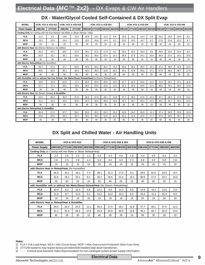
Electrical Data (MC™ 2x2) - DX Evaps & CW Air Handlers
DX Split and Chilled Water - Air Handling Units
MODEL VCH & VCC-012 VCH & VCC-018 & 024 VCH & VCC-030 & 036
Power Supply 208/1/60 277/1/60 208/3/60 460/3/60 208/1/60 277/1/60 208/3/60 460/3/60 208/1/60 277/1/60 208/3/60 460/3/60
Cooling Only (or Cooling with Hot Water or Steam Reheat/Heat)
FLA 2.2 2.0 2.2 1.1 4.0 3.2 4.0 1.8 5.4 3.9 5.4 2.2
MCA 2.8 2.5 2.8 1.4 5.0 4.0 5.0 2.3 6.8 4.9 6.8 2.8
MOP 15 15 15 15 15 15 15 15 15 15 15 15
with Electric Heat or Reheat/Heat (No Humidifier)
FLA 26.3 20.1 16.1 7.4 28.1 21.3 17.9 8.1 29.5 22.0 19.3 8.5
MCA 32.9 25.1 20.1 9.2 35.1 26.6 22.4 10.1 36.9 27.5 24.1 10.6
MOP 35 30 25 15 40 40 25 15 40 30 25 15
with Humidifier with or without Hot Water/Steam Reheat/Heat (No Electric Reheat/Heat)
FLA 10.4 8.2 10.4 4.8 12.2 9.4 12.2 5.5 13.6 10.1 13.6 5.9
MCA 11.0 8.7 11.0 5.1 13.2 10.2 13.2 6.0 15.0 11.1 15.0 6.5
MOP 15 15 15 15 15 15 15 15 20 15 20 15
with Electric Heat or Reheat/Heat & Humidifier
FLA 34.5 26.3 24.3 11.1 36.3 27.5 26.1 11.8 37.7 28.2 27.5 12.2
MCA 41.1 31.3 28.3 12.9 43.3 32.8 30.6 13.8 45.1 33.7 32.3 14.3
MOP 45 35 30 15 45 35 35 15 50 35 35 15
DX - Water/Glycol Cooled Self-Contained & DX Split EvapMODEL VCW, VCG & VCE-012 VCW, VCG & VCE-018 VCW, VCG & VCE-024 VCW, VCG & VCE-030 VCW, VCG & VCE-036
Power Supply 208/1/60 277/1/60 208/1/60 277/1/60 208/1/60 277/1/60 208/3/60 460/3/60 208/1/60 277/1/60 208/3/60 460/3/60 208/1/60 277/1/60 208/3/60 460/3/60
Cooling Only (or Cooling with Hot Gas Reheat, Hot Water or Steam Reheat / Heat)
FLA 11.2 9.1 13.6 10.9 16.8 14.1 12.3 6.9 19.5 16.1 14.4 7.8 23.3 19.9 18.9 8.2
MCA 13.5 10.9 16.0 12.8 20.0 16.8 14.4 8.2 23.0 19.2 16.7 9.2 27.8 23.9 22.3 9.7
MOP 20 15 25 20 30 25 20 15 35 30 25 15 45 40 35 15
with Electric Heat (No Electric Reheat or Humidifier)
FLA 26.3 20.1 28.1 21.3 28.1 21.3 17.9 8.1 29.5 22.0 19.3 8.5 29.5 22.0 19.3 8.5
MCA 32.9 25.1 35.1 26.6 35.1 26.6 22.4 10.1 36.9 27.5 24.1 10.6 36.9 27.5 24.1 10.6
MOP 35 30 40 30 40 30 25 15 40 30 25 15 45 40 35 15
with Electric Reheat/Heat (No Humidifier)
FLA 35.3 27.2 37.7 29.0 40.9 32.2 26.2 13.2 43.6 34.2 28.3 14.1 47.4 38.0 32.8 14.5
MCA 43.6 33.5 46.1 35.4 50.1 39.4 31.8 16.0 53.1 41.8 34.0 17.1 57.9 46.5 39.7 17.6
MOP 45 35 50 40 60 45 35 20 60 45 35 20 60 50 45 20
with Humidifier with or without Hot Gas Reheat, Hot Water/Steam Reheat/Heat(No Electric Reheat/Heat)
FLA 19.4 15.3 21.8 17.1 25.0 20.3 20.5 10.6 27.7 22.3 22.6 11.5 31.5 26.1 27.1 11.9
MCA 21.7 17.1 24.2 19.0 28.2 23.0 22.6 11.9 31.2 25.4 24.9 12.9 36.0 30.1 30.5 13.4
MOP 30 20 30 25 40 30 30 15 45 35 30 15 50 45 40 15
with Electric Heat (No Electric Reheat) & Humidifier
FLA 34.5 26.3 36.3 27.5 36.3 27.5 26.1 11.8 37.7 28.2 27.5 12.2 37.7 28.2 27.5 12.2
MCA 41.1 31.3 43.3 32.8 43.3 32.8 30.6 13.8 45.1 33.7 32.3 14.3 45.1 33.7 32.3 14.3
MOP 45 35 45 35 45 35 35 15 50 35 35 15 50 45 40 15
with Electric Reheat/Heat & Humidifier
FLA 35.3 27.2 37.7 29.0 40.9 32.2 26.2 13.2 43.6 34.2 28.3 14.1 47.4 38.0 32.8 14.5
MCA 43.6 33.5 46.1 35.4 50.1 39.4 31.8 16.0 53.1 41.8 34.0 17.1 57.9 46.5 39.7 17.6
MOP 45 35 50 40 60 45 35 20 60 45 35 20 60 50 45 20
Notes:1) FLA = Full Load Amps; MCA = Min Circuit Amps; MOP = Max Overcurrent Protection (Max Fuse Size)2) 277/1/60 systems may require factory provided field installed step-down transformer.3) - - - - Consult local AboveAir Sales Representative for non-cataloged system power supply information.
AboveAir™ MissionCritical™ A/C’s AboveAir Technologies (MC22-L10)10 Electrical Data
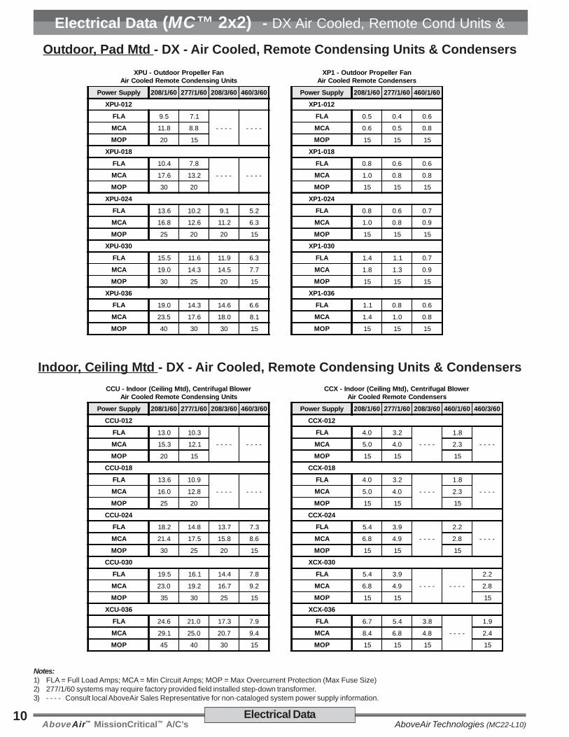
Electrical Data (MC™ 2x2) - DX Air Cooled, Remote Cond Units &CondsOutdoor, Pad Mtd - DX - Air Cooled, Remote Condensing Units & Condensers
XPU - Outdoor Propeller FanAir Cooled Remote Condensing Units
XP1 - Outdoor Propeller FanAir Cooled Remote Condensers
Power Supply 208/1/60 277/1/60 208/3/60 460/3/60 Power Supply 208/1/60 277/1/60 460/1/60
XPU-012 XP1-012
FLA 9.5 7.1
- - - - - - - -
FLA 0.5 0.4 0.6
MCA 11.8 8.8 MCA 0.6 0.5 0.8
MOP 20 15 MOP 15 15 15
XPU-018 XP1-018
FLA 10.4 7.8
- - - - - - - -
FLA 0.8 0.6 0.6
MCA 17.6 13.2 MCA 1.0 0.8 0.8
MOP 30 20 MOP 15 15 15
XPU-024 XP1-024
FLA 13.6 10.2 9.1 5.2 FLA 0.8 0.6 0.7
MCA 16.8 12.6 11.2 6.3 MCA 1.0 0.8 0.9
MOP 25 20 20 15 MOP 15 15 15
XPU-030 XP1-030
FLA 15.5 11.6 11.9 6.3 FLA 1.4 1.1 0.7
MCA 19.0 14.3 14.5 7.7 MCA 1.8 1.3 0.9
MOP 30 25 20 15 MOP 15 15 15
XPU-036 XP1-036
FLA 19.0 14.3 14.6 6.6 FLA 1.1 0.8 0.6
MCA 23.5 17.6 18.0 8.1 MCA 1.4 1.0 0.8
MOP 40 30 30 15 MOP 15 15 15
Indoor, Ceiling Mtd - DX - Air Cooled, Remote Condensing Units & CondensersCCU - Indoor (Ceiling Mtd), Centrifugal Blower
Air Cooled Remote Condensing UnitsCCX - Indoor (Ceiling Mtd), Centrifugal Blower
Air Cooled Remote Condensers
Power Supply 208/1/60 277/1/60 208/3/60 460/3/60 Power Supply 208/1/60 277/1/60 208/3/60 460/1/60 460/3/60
CCU-012 CCX-012
FLA 13.0 10.3
- - - - - - - -
FLA 4.0 3.2
- - - -
1.8
- - - -MCA 15.3 12.1 MCA 5.0 4.0 2.3
MOP 20 15 MOP 15 15 15
CCU-018 CCX-018
FLA 13.6 10.9
- - - - - - - -
FLA 4.0 3.2
- - - -
1.8
- - - -MCA 16.0 12.8 MCA 5.0 4.0 2.3
MOP 25 20 MOP 15 15 15
CCU-024 CCX-024
FLA 18.2 14.8 13.7 7.3 FLA 5.4 3.9
- - - -
2.2
- - - -MCA 21.4 17.5 15.8 8.6 MCA 6.8 4.9 2.8
MOP 30 25 20 15 MOP 15 15 15
CCU-030 XCX-030
FLA 19.5 16.1 14.4 7.8 FLA 5.4 3.9
- - - - - - - -
2.2
MCA 23.0 19.2 16.7 9.2 MCA 6.8 4.9 2.8
MOP 35 30 25 15 MOP 15 15 15
XCU-036 XCX-036
FLA 24.6 21.0 17.3 7.9 FLA 6.7 5.4 3.8
- - - -
1.9
MCA 29.1 25.0 20.7 9.4 MCA 8.4 6.8 4.8 2.4
MOP 45 40 30 15 MOP 15 15 15 15
Notes:1) FLA = Full Load Amps; MCA = Min Circuit Amps; MOP = Max Overcurrent Protection (Max Fuse Size)2) 277/1/60 systems may require factory provided field installed step-down transformer.3) - - - - Consult local AboveAir Sales Representative for non-cataloged system power supply information.
AboveAir™ MissionCritical™ A/C’sAboveAir Technologies (MC22-L10)11Electrical Data
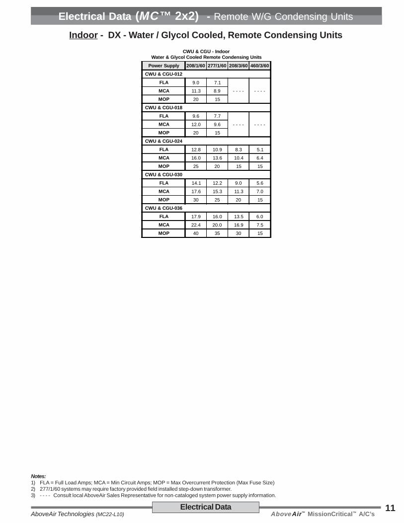
Electrical Data (MC™ 2x2) - Remote W/G Condensing Units
Notes:1) FLA = Full Load Amps; MCA = Min Circuit Amps; MOP = Max Overcurrent Protection (Max Fuse Size)2) 277/1/60 systems may require factory provided field installed step-down transformer.3) - - - - Consult local AboveAir Sales Representative for non-cataloged system power supply information.
CWU & CGU - IndoorWater & Glycol Cooled Remote Condensing Units
Power Supply 208/1/60 277/1/60 208/3/60 460/3/60
CWU & CGU-012
FLA 9.0 7.1
- - - - - - - -MCA 11.3 8.9
MOP 20 15
CWU & CGU-018
FLA 9.6 7.7
- - - - - - - -MCA 12.0 9.6
MOP 20 15
CWU & CGU-024
FLA 12.8 10.9 8.3 5.1
MCA 16.0 13.6 10.4 6.4
MOP 25 20 15 15
CWU & CGU-030
FLA 14.1 12.2 9.0 5.6
MCA 17.6 15.3 11.3 7.0
MOP 30 25 20 15
CWU & CGU-036
FLA 17.9 16.0 13.5 6.0
MCA 22.4 20.0 16.9 7.5
MOP 40 35 30 15
Indoor - DX - Water / Glycol Cooled, Remote Condensing Units
AboveAir™ MissionCritical™ A/C’s AboveAir Technologies (MC22-L10)12
safety switches. The circuit shall bedesigned to shut down all system waterproducing operations in the event of anoverflow condition.
2.1.3.1 Main Power, Non-FusedDisconnect(VC_ Evap Section)
The indoor evaporator section shall beprovided with a factory installed main powernon-fused disconnect. The disconnectshall be NEMA rated for indoor or outdoorinstallation as required.
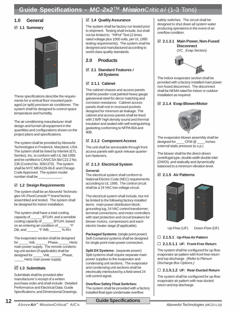
2.1.4 Evap Blower/Motor
The evaporator blower assembly shall bedesigned for ____ CFM @ ____ inchesexternal static pressure (e.s.p.)
The blower shall be the direct-drivencentrifugal type, double width double inlet(DWDI), and statically and dynamicallybalanced to a minimum vibration level.
2.1.5 Air Patterns
Up-Flow (UF) Down-Flow (DF)
2.1.5.1 Up-Flow Air Pattern
2.1.5.1.1 UF: Front-Free Return
The system shall be configured for up-flowevaporator air pattern with front-free returnand top discharge. (Refer to PlenumDischarge Box Options.)
2.1.5.1.2 UF: Rear-Ducted Return
The system shall be configured for up-flowevaporator air pattern with rear ductedreturn and top discharge.
1.0 General 1.1 Summary
These specifications describe the require-ments for a vertical floor mounted pack-aged (or split) precision air conditioner. Thesystem shall be designed to control spacetemperature and humidity.
The air conditioning manufacturer shalldesign and furnish all equipment in thequantities and configurations shown on theproject plans and specifications.
The system shall be provided by AboveAirTechnologies in Frederick, Maryland, USA.The system shall be listed by Intertek (ETLSemko), Inc. to conform with UL Std 1995and be certified to CAN/CSA Std C22.2 No.236 (Control No. 3091370). The systemshall be NYC MEA229-06-E and ChicagoCode Approved. The system modelnumber shall be _____________.
1.2 Design RequirementsThe system shall be an AboveAir Technolo-gies VK-FloorConsole™ brand factoryassembled and tested. The system shallbe designed for indoor installation.
The system shall have a total coolingcapacity of ______ BTU/H, and a sensiblecooling capacity of ______ BTU/H, basedon an entering air condition of ______ °FDB, and ______ °F WB, ______ % RH.
The evaporator section shall be designedfor _____ Volt, ______ Phase, _____ Hertzmain power supply. The remote condens-ing unit section (if applicable) shall bedesigned for _____ Volt, ______ Phase,_____ Hertz main power supply.
1.3 SubmittalsSubmittals shall be provided aftermanufacturer’s receipt of a writtenpurchase order and shall include: DetailedPerformance and Electrical Data; GuideSpecifications; and Dimensional Drawings.
1.4 Quality AssuranceThe system shall be factory run tested priorto shipment. Testing shall include, but shallnot be limited to: “HiPot” Test (2 timesrated voltage plus 1000 volts, per UL 1995testing requirements). The system shall bedesigned and manufactured according toworld class quality standards.
2.0 Products
2.1 Standard Features /All Systems
2.1.1 CabinetThe cabinet chassis and access panelsshall be powder-coat painted heavy gaugegalvanneal steel for decor matching andcorrosion resistance. Cabinet accesspanels shall rest in recessed pocketsdesigned for minimum air leakage. Thecabinet and access panels shall be linedwith 2 lb/ft2 high density sound and thermalinsulation and sealed with self-extinguishinggasketing conforming to NFPA 90A and90B.
2.1.2 Component AccessThe unit shall be serviceable through frontaccess panels with quick-release quarter-turn fasteners.
2.1.3 Electrical SystemGeneral:The electrical system shall conform toNational Electric Code (NEC) requirementsaccording to UL 1995. The control circuitshall be a 24 VAC low voltage circuit.
The electrical system shall include, but notbe limited to the following factory installeditems: main power distribution block;grounding lug; 24 VAC control transformer;terminal connections; and motor controllerswith start protection and circuit breakers forblower motors, compressors and eachelectric heater stage (if applicable).
Packaged Systems: (single point power)Self-Contained systems shall be designedfor single point main power connection.
Split DX Systems: (separate power)Split systems shall require separate mainpower supplies to the evaporator andcondensing unit sections. The evaporatorand condensing unit sections shall beelectrically interlocked by a field wired 24volt control signal.
Overflow Safety Float Switches:The system shall be provided with a factoryinstalled float type condensate overflow
Guide Specifications
Guide Specifications - MC-2x2™ MissionCritical (1-3 Tons)
AboveAir™ MissionCritical™ A/C’sAboveAir Technologies (MC22-L10)13Guide Specifications
Guide Specifications - MC-2x2™ MissionCritical (1-3 Tons) 2.1.5.2 Down-Flow Air Pattern
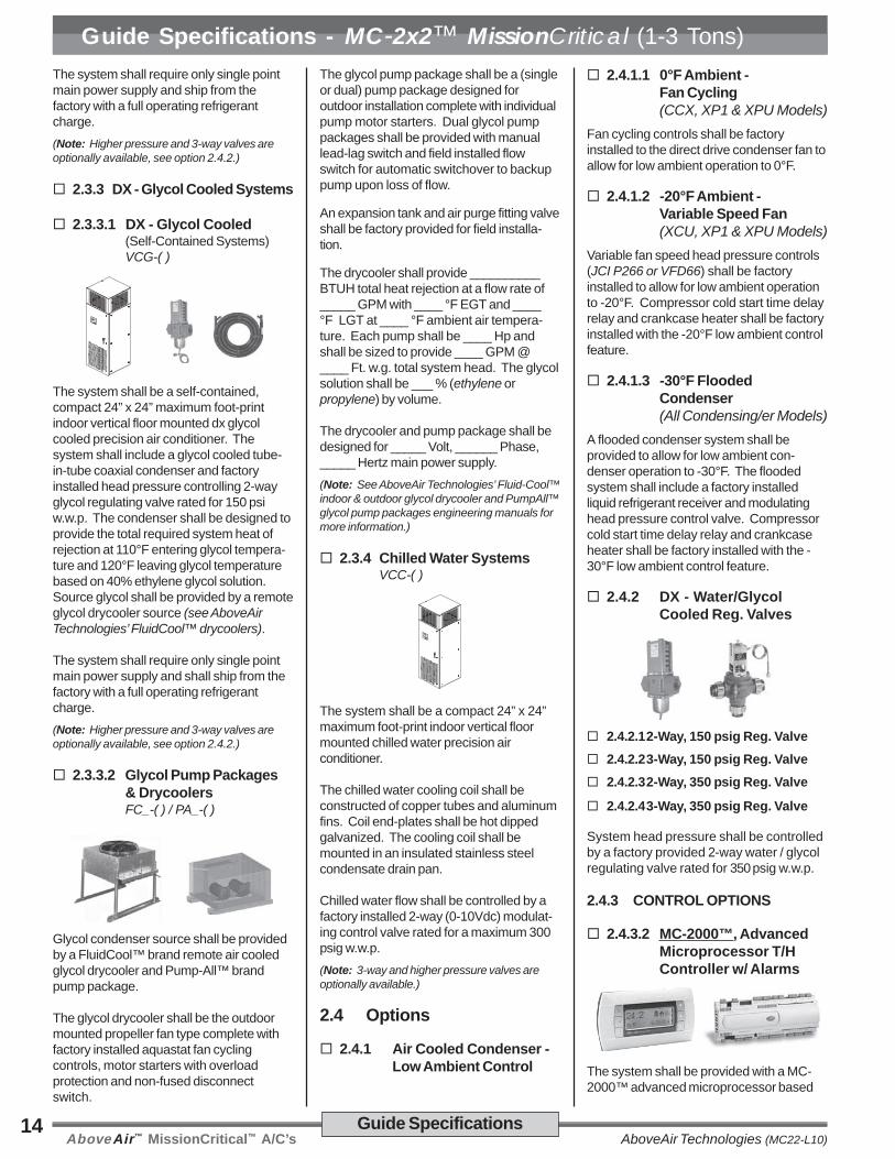
The system shall be configured for down-flow evaporator air pattern with top free orducted return and bottom discharge intoraised floor. (Refer to Floor Stand Options.)
2.1.6 Air FiltrationThe filter(s) shall be ___ inch thick pleatedand rated for 30% dust spot efficiency(based on ASHRAE 52.1). The filter(s)shall be serviceable through front of thesystem.
2.2 Direct Expansion Systems
2.2.1 DX - Evaporator Coil
The DX evaporator coil shall be con-structed of copper tubes and aluminumfins. The system shall be designed for adraw-through air pattern for maximum heattransfer. Coil end-plates shall be hot dippedgalvanized. The evaporator coil shall bemounted in an insulated stainless steelcondensate drain pan.
2.2.2 Scroll Compressor
Each compressor shall be the highefficiency, low sound Scroll type mountedon vibration isolators and located in aseparate compartment out of the evapora-tor air stream to facilitate servicing whileequipment is operating. Each compressorshall be complete with reversible positive oilpump, charging and service ports, internalspring isolation, and discharge gas vibrationeliminator.
2.2.3 DX - Refrigeration Circuit
Each refrigeration circuit shall be pre-pipedwith type “L” refrigerant copper tubing. Therefrigeration system shall include but not be
limited to: expansion valve with externalequalizer and rapid bleed-through capacity.Features shall include filter dryer, sightglass, pressure fittings and high pressure/low pressure safety cutouts.
2.3 Standard Features /Individual Systems
2.3.1 DX - Air Cooled Systems
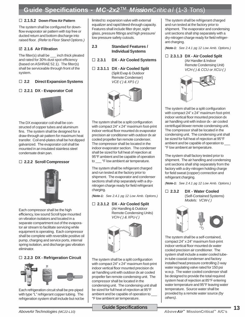
2.3.1.1 DX - Air Cooled Split(Split Evap & OutdoorRemote Condenser)VCE-( ) & XP1-( )
The system shall be a split configurationwith compact 24” x 24” maximum foot-printindoor vertical floor mounted dx evaporatorprecision air conditioner with outdoor dx aircooled propeller fan remote condenser.The compressor shall be located in theindoor evaporator section. The condensershall be sized for full heat of rejection at95°F ambient and be capable of operationto ___ °F low ambient air temperature.
The system shall be refrigerant chargedand run tested at the factory prior toshipment. The evaporator and condensersections shall ship separately with a dry-nitrogen charge ready for field refrigerantcharging.(Note-1: See 2.4.1 pg 12 Low Amb. Options.)
2.3.1.2 DX - Air Cooled Split(Air Handling & OutdoorRemote Condensing Units)VCH-( ) & XPU-( )
The system shall be a split configurationwith compact 24” x 24” maximum foot-printindoor vertical floor mounted precision dxair handling unit with outdoor dx air cooledpropeller fan remote condensing unit. Thecompressor shall be located in thecondensing unit. The condensing unit shallbe sized for full heat of rejection at 95°Fambient and be capable of operation to ___°F low ambient air temperature.
The system shall be refrigerant chargedand run tested at the factory prior toshipment. The evaporator and condensingunit sections shall ship separately with adry-nitrogen charge ready for field refriger-ant charging.(Note-1: See 2.4.1 pg 12 Low Amb. Options.)
2.3.1.3 DX - Air Cooled Split(Air Handler & IndoorRemote Condensing Unit)VCH-( ) & CCU or XCU-( )
The system shall be a split configurationwith compact 24” x 24” maximum foot-printindoor vertical floor mounted precision dxair handling unit with indoor dx - air cooledcentrifugal blower remote condensing unit.The compressor shall be located in thecondensing unit. The condensing unit shallbe sized for full heat of rejection at 95°Fambient and be capable of operation to ___°F low ambient air temperature.
The system shall factory tested prior toshipment. The air handling and condensingunit sections shall ship separately from thefactory with a dry-nitrogen holding chargefor field sweat (copper) connection andrefrigerant charging.(Note-1: See 2.4.1 pg 12 Low Amb. Options.)
2.3.2 DX - Water Cooled(Self-Contained Systems)Models: VCW-( )
The system shall be a self-contained,compact 24” x 24” maximum foot-printindoor vertical floor mounted dx watercooled precision air conditioner. Thesystem shall include a water cooled tube-in-tube coaxial condenser and factoryinstalled head pressure controlling 2-waywater regulating valve rated for 150 psiw.w.p. The water cooled condenser shallbe designed to provide the total requiredsystem heat of rejection at 85°F enteringwater temperature and 95°F leaving watertemperature. Source water shall beprovided by a remote water source (byothers).
AboveAir™ MissionCritical™ A/C’s AboveAir Technologies (MC22-L10)14 Guide Specifications
Guide Specifications - MC-2x2™ MissionCritical (1-3 Tons)The system shall require only single pointmain power supply and ship from thefactory with a full operating refrigerantcharge.(Note: Higher pressure and 3-way valves areoptionally available, see option 2.4.2.)
2.3.3 DX - Glycol Cooled Systems
2.3.3.1 DX - Glycol Cooled(Self-Contained Systems)VCG-( )
The system shall be a self-contained,compact 24” x 24” maximum foot-printindoor vertical floor mounted dx glycolcooled precision air conditioner. Thesystem shall include a glycol cooled tube-in-tube coaxial condenser and factoryinstalled head pressure controlling 2-wayglycol regulating valve rated for 150 psiw.w.p. The condenser shall be designed toprovide the total required system heat ofrejection at 110°F entering glycol tempera-ture and 120°F leaving glycol temperaturebased on 40% ethylene glycol solution.Source glycol shall be provided by a remoteglycol drycooler source (see AboveAirTechnologies’ FluidCool™ drycoolers).
The system shall require only single pointmain power supply and shall ship from thefactory with a full operating refrigerantcharge.(Note: Higher pressure and 3-way valves areoptionally available, see option 2.4.2.)
2.3.3.2 Glycol Pump Packages& DrycoolersFC_-( ) / PA_-( )
Glycol condenser source shall be providedby a FluidCool™ brand remote air cooledglycol drycooler and Pump-All™ brandpump package.
The glycol drycooler shall be the outdoormounted propeller fan type complete withfactory installed aquastat fan cyclingcontrols, motor starters with overloadprotection and non-fused disconnectswitch.
The glycol pump package shall be a (singleor dual) pump package designed foroutdoor installation complete with individualpump motor starters. Dual glycol pumppackages shall be provided with manuallead-lag switch and field installed flowswitch for automatic switchover to backuppump upon loss of flow.
An expansion tank and air purge fitting valveshall be factory provided for field installa-tion.
The drycooler shall provide __________BTUH total heat rejection at a flow rate of_____ GPM with ____ °F EGT and ____°F LGT at ____ °F ambient air tempera-ture. Each pump shall be ____ Hp andshall be sized to provide ____ GPM @____ Ft. w.g. total system head. The glycolsolution shall be ___ % (ethylene orpropylene) by volume.
The drycooler and pump package shall bedesigned for _____ Volt, ______ Phase,_____ Hertz main power supply.(Note: See AboveAir Technologies’ Fluid-Cool™indoor & outdoor glycol drycooler and PumpAll™glycol pump packages engineering manuals formore information.)
2.3.4 Chilled Water SystemsVCC-( )
The system shall be a compact 24” x 24”maximum foot-print indoor vertical floormounted chilled water precision airconditioner.
The chilled water cooling coil shall beconstructed of copper tubes and aluminumfins. Coil end-plates shall be hot dippedgalvanized. The cooling coil shall bemounted in an insulated stainless steelcondensate drain pan.
Chilled water flow shall be controlled by afactory installed 2-way (0-10Vdc) modulat-ing control valve rated for a maximum 300psig w.w.p.(Note: 3-way and higher pressure valves areoptionally available.)
2.4 Options
2.4.1 Air Cooled Condenser -Low Ambient Control
2.4.1.1 0°F Ambient -Fan Cycling(CCX, XP1 & XPU Models)
Fan cycling controls shall be factoryinstalled to the direct drive condenser fan toallow for low ambient operation to 0°F.
2.4.1.2 -20°F Ambient -Variable Speed Fan(XCU, XP1 & XPU Models)
Variable fan speed head pressure controls(JCI P266 or VFD66) shall be factoryinstalled to allow for low ambient operationto -20°F. Compressor cold start time delayrelay and crankcase heater shall be factoryinstalled with the -20°F low ambient controlfeature.
2.4.1.3 -30°F FloodedCondenser(All Condensing/er Models)
A flooded condenser system shall beprovided to allow for low ambient con-denser operation to -30°F. The floodedsystem shall include a factory installedliquid refrigerant receiver and modulatinghead pressure control valve. Compressorcold start time delay relay and crankcaseheater shall be factory installed with the -30°F low ambient control feature.
2.4.2 DX - Water/GlycolCooled Reg. Valves
2.4.2.12-Way, 150 psig Reg. Valve 2.4.2.23-Way, 150 psig Reg. Valve 2.4.2.32-Way, 350 psig Reg. Valve
2.4.2.43-Way, 350 psig Reg. Valve
System head pressure shall be controlledby a factory provided 2-way water / glycolregulating valve rated for 350 psig w.w.p.
2.4.3 CONTROL OPTIONS
2.4.3.2 MC-2000™, AdvancedMicroprocessor T/HController w/ Alarms
The system shall be provided with a MC-2000™ advanced microprocessor based
AboveAir™ MissionCritical™ A/C’sAboveAir Technologies (MC22-L10)15Guide Specifications
Guide Specifications - MC-2x2™ MissionCritical (1-3 Tons)temperature and humidity controller withalarms.
Select Features/Benefits:• 4x20 Character Liquid Crystal
Alpha-numerical Display• User Configurable• Run-Time Hours• Current Unit Mode Status• Alarm Status• Digital & Analog Inputs / Outputs• Temperature Anticipation• Remote Stop / Start Contact• Summary Alarm Contact• Automatic or Manual (selectable)
Restart After Power Loss• Sequential Load After Restart• Recovery Delay• Compressor Short Cycle Timers• Cold Start Time Delay• Security Password Access• Self-Diagnostics• Service Mode
Unit Status DisplayThe control system shall display currentunit functions and room status (ifapplicable):
• Current Dry Bulb Temp Set Point• Current Relative Humidity Set Point• System ON/OFF• Cooling• Heating• Humidifying• Dehumidifying• Reheating• Actual Room DB Temperature• Actual Room Relative Humidity
Alarm Conditions:Alarm conditions activate an audible andvisual indicator plus close a summaryalarm dry contact connection. The controlsystem shall alert to the following alarmconditions (if applicable):
• High Temperature • High Head Press• Low Temperature • Smoke Detection• High Humidity • Firestat• Low Humidity • Leak Detection• Sensor Failure • Sensor Failure• Summary Failure • Loss of Power
• Loss of Air Flow• Dirty Filter
Digital & Analog Control Inputs /Outputs:The control system shall be capable of bothdigital (ON/OFF) and analog (proportionalintegral, PI) input and output control.
Select MC-2000 Options: Multi-Unit N+1 Sequencing
BMS Communications Interface:
ModBus RS485 Serial Connection BACnet over MS/TP (RS485 Serial) BACnet Over IP (Ethernet / EIA485) LonWorks FTT10 (RS485 Serial)
2.4.4 HEAT OPTIONS
2.4.4.1 Electric Reheat/Heat
An electric heating system shall be factoryinstalled to provide:
Electric Heat Only during heat mode
Electric Reheat to offset sensiblecooling during the dehumidifica-tion mode and to provide heatingduring heat mode.
Heater elements shall be the low-wattdensity finned-tubular type. The heatershall be complete with individual heaterstage starter/contactor and overheatsafeties. Systems incorporating factoryinstalled electric heaters shall require onlysingle point power to the main unit powerdistribution. The electric heat shall have acapacity of _________ BTU/H and a KWrating of ___ KW, controlled in ___ stages.
2.4.4.1.1 SCR Fired Heat/Reheat(Requires MC-2000™)
The electric heat/reheat shall be controlledthrough a “zero firing” silicon controlrectifier (SCR) with an extruded aluminumheat sink and solid state logic system toprovide close dry bulb temperature controlof the leaving conditioned air temperature.The electric heat shall have a capacity of_________ BTUH and a KW rating of ___KW.
2.4.4.2 Hot Gas ReheatThe system shall be provided with a hotgas reheat coil with 3-way heat reclaimcontrol valve and liquid refrigerant storagereceiver. The hot gas reheat coil shall besized to provide free-energy space neutralleaving air temperature by offsetting thesensible cooling during dx compressoroperation.(Note: Hot Gas Reheat is not available onsystems with compressor located in remotecondensing unit section.)
2.4.4.3 Hot Water Heat
A Hot Water Heating system shall befactory provided. The hot water heatingsystem shall be complete a factory
installed aluminum fin, copper tube hotwater coil and field installed 2-way motor-ized hot water control valve. Hot watershall be provided by a remote source at thespecified flow rate and temperature. Thehot water heating system shall have a ratedcapacity of _________ BTUH @ ______GPM, _____°F EWT.
2.4.4.4 Steam HeatA Steam Heating system shall be factoryprovided. The steam heating system shallbe complete a factory installed aluminumfin, copper tube steam coil and fieldinstalled 2-way motorized steam ratedcontrol valve. Steam piping specialtiesshall be field provided. Steam shall beprovided by a remote source at thespecified temperature and pressure. Thesteam heating system shall have a ratedcapacity of _________ BTUH @ ____ psigsaturated steam.
2.4.4.5 Heat Pump OptionThe system shall include a factory installedheat pump heating cycle including revers-ing valve, automatic defrost cycle (ifapplicable) and remote wall mountedtemperature controller with auxiliary heatingcontrol capability. The heat pump modeheating capacity shall be _______ BTUH.
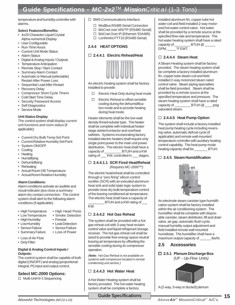
2.4.5 Steam Humidification
An electrode steam canister type humidifi-cation system shall be factory installedwithin the air conditioning system. Thehumidifier shall be complete with dispos-able canister, steam distributor, fill and drainvalve, air gap, automatic flush cycle,manual humidity output adjustment andfield installed remote wall mountedhumidistat. The humidifier shall have amaximum output capacity of ______ lbs/hr.
2.5 Accessories
2.5.1 Plenum Discharge Box(UF - Up-Flow Units)
A (2-way, 3-way or ducted) plenum

AboveAir™ MissionCritical™ A/C’s AboveAir Technologies (MC22-L10)16 Guide Specifications
Guide Specifications - MC-2x2™ MissionCritical (1-3 Tons)discharge box shall be provided for fieldinstallation to the top of the up-flow unit.The plenum box shall be 18.5 inches high,insulated and powder-coat painted tomatch the color of the unit.
2.5.2 Floor Stand
A ____ inch high floor stand shall be factoryprovided for field installation. The floorstand shall have adjustable legs withvibration isolation.
2.5.2.1 Turning VanesTurning vanes shall be factory provided withthe floor stand to direct the discharge aireither to the front or rear of the unit.
2.5.3 Condensate Pump(Factory Installed)
A condensate pump shall be factoryprovided and installed within the indoorevaporator section. The condensate pumpshall be provided with dual internal floatswitches: one for pump operation initiationand the other for pump reservoir overflowsafety.
2.5.4 Hot Gas Bypass Systems
2.5.4.1 Hot Gas Bypass ToEvaporator Inlet
Each refrigerant circuit shall be providedwith a factory installed hot gas (discharge)bypass valve. The hot gas bypass valveshall be designed to supply hot gas toevaporator inlet as required to provide coilfreeze-protection and capacity modulationunder low load conditions.
2.5.4.2 Hot Gas Bypass ToSuction Line withQuench Valve(VCH/XPU-CCU/CWU-CGURemote Condensing Units3rd Line Not Required!)
Each refrigerant circuit of the Split DXsystem shall be provided with a factoryinstalled hot gas bypass system to include:hot gas (discharge) bypass anddesuperheating quench. The hot gasbypass system shall be designed to supplyhot gas and liquid refrigerant to the suctionline as required to provide coil freeze-protection and capacity modulation underlow load conditions. All hot gas bypasscomponents shall be factory installed andshall not require additional field refrigerantlines on split DX systems.
2.5.5 Suction-Line Accumulator
Each refrigerant circuit shall be providedwith a factory installed Suction-LineAccumulator to prevent liquid slugging ofthe compressor and excessive refrigerantdilution of the compressor oil during lowload conditions. The accumulator shallreturn refrigerant and oil to the compressorat a sufficient rate to maintain both systemoperating efficiency and proper oil level.The accumulators shall be wrapped with a1/2” closed-cell neoprene insulation toprevent sweating.
2.5.6 Main Power, Non-FusedDisconnects(Remote Condenser Section)
The remote condensing unit (or condenser)shall be factory provided with a main powernon-fused disconnect for field installation.The disconnect shall be NEMA rated forindoor or outdoor installation as required.
2.5.7 Firestat(Factory Installed)
A Firestat shall be factory installed in thereturn air stream of the unit and wired to theA/C unit electrical control panel. TheFirestat shall shut-down all A/C systemoperations upon sensing a high return airtemperature condition.
2.5.8 Smoke Detector(Factory Installed)
A Smoke Detector shall be factory installedin the return air stream of the unit and wiredto the A/C unit electrical control panel. TheSmoke Detector shall shut-down all A/Csystem operations upon activation.
2.5.9 Remote Water-LeakDetector
A remote water-leak detector shall befactory provided for field installation. Theremote water-leak detector shall be wiredto shut down all A/C unit water producingfunctions upon sensing a water leak.
2.5.10 Flow Switch -Water/Glycol Condenser
A factory installed flow switch shall shut-down / lockout compressor operation priorto the high refrigerant pressure switchalarm upon sensing a loss or low dxcondenser water/glycol flow. A flow switchalarm shall be indicated both via MC-2000microprocessor display and auxililary dry-contact terminal connection.
2.5.11 Compressor Acoustic /Sound Jacket
Each compressor shall be provided with afactory installed compressor sound jacketwith snap closure system for ease ofremoval and reinstallation. Sound jacketsshall have a noise reduction coefficient(NRC) of 85 per ASTM and C-423 and asound transmission lost (STC) of 11 perASTM E-90.
AboveAir™ MissionCritical™ A/C’sAboveAir Technologies (MC22-L10)17Dimensional Data
Dimensional Data - Available Configurations, MissionCritical™ A/C’s
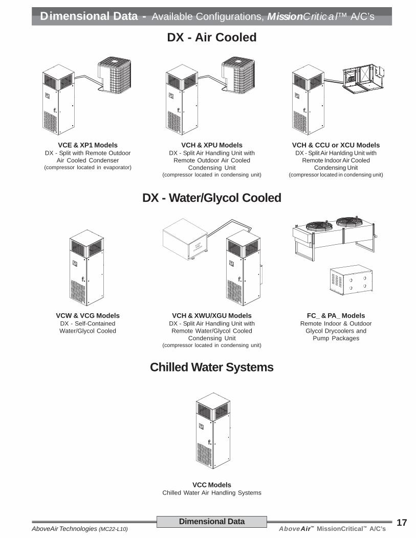
DX - Air Cooled
DX - Water/Glycol Cooled
Chilled Water Systems
VCE & XP1 ModelsDX - Split with Remote Outdoor
Air Cooled Condenser(compressor located in evaporator)
VCH & XPU ModelsDX - Split Air Handling Unit with
Remote Outdoor Air CooledCondensing Unit
(compressor located in condensing unit)
VCH & CCU or XCU ModelsDX - Split Air Hanlding Unit with
Remote Indoor Air CooledCondensing Unit
(compressor located in condensing unit)
VCW & VCG ModelsDX - Self-ContainedWater/Glycol Cooled
VCC ModelsChilled Water Air Handling Systems
ACCESS
PANEL
(Compressors)
VCH & XWU/XGU ModelsDX - Split Air Handling Unit withRemote Water/Glycol Cooled
Condensing Unit(compressor located in condensing unit)
FC_ & PA_ ModelsRemote Indoor & Outdoor
Glycol Drycoolers andPump Packages
AboveAir™ MissionCritical™ A/C’s AboveAir Technologies (MC22-L10)18
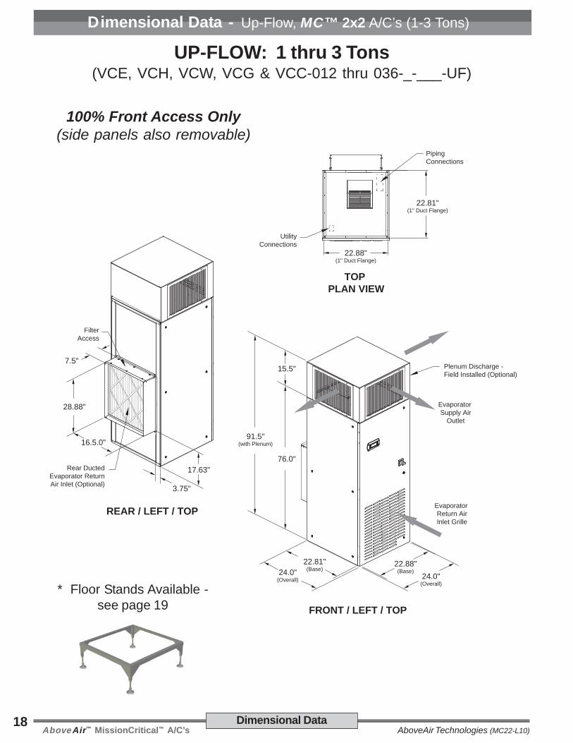
22.88"(1" Duct Flange)
22.81"(1" Duct Flange)
TOP PLAN VIEW
UtilityConnections
PipingConnections
7.5"
28.88"
16.5.0"
17.63"
3.75"
Rear DuctedEvaporator Return Air Inlet (Optional)
FilterAccess
22.88"(Base)
24.0"(Overall)
22.81"(Base)24.0"
(Overall)
76.0"
91.5"(with Plenum)
15.5"
Evaporator Return AirInlet Grille
Plenum Discharge -Field Installed (Optional)
Evaporator Supply Air
Outlet
REAR / LEFT / TOP
FRONT / LEFT / TOP
Dimensional Data
Dimensional Data - Up-Flow, MC™ 2x2 A/C’s (1-3 Tons)
UP-FLOW: 1 thru 3 Tons(VCE, VCH, VCW, VCG & VCC-012 thru 036-_-___-UF)
100% Front Access Only(side panels also removable)
* Floor Stands Available -see page 19
AboveAir™ MissionCritical™ A/C’sAboveAir Technologies (MC22-L10)19
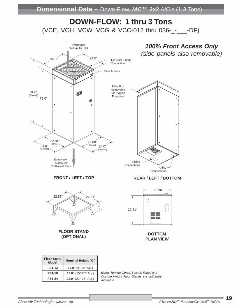
Note: Turning Vanes, Seismic Rated andCustom Height Floor Stands are optionallyavailable.
22.88"(Base) 24.0"
(Overall)
22.81"(Base)24.0"
(Overall)
76.0"
81.0"(Overall)
Filter BoxRemovableFor RiggingPurposes
Evaporator Return Air Inlet
Evaporator Supply Air
To Raised Floor
1.0" Duct FlangeConnection
Filter Access
REAR / LEFT / BOTTOMFRONT / LEFT / TOP
22.81"
C
FLOOR STAND(OPTIONAL)
22.88"
PipingConnections
UtilityConnections
24.0" 24.0"
22.81"
BOTTOMPLAN VIEW
22.88"
dnatSroolFledoM
"C"thgieHlanimoN
21-1SF "0.21 jdA"41-"9( .)
81-1SF "0.81 ).jdA"02-"51(
42-1SF "0.42 ).jdA"62-"12(
Dimensional Data - Down-Flow, MC™ 2x2 A/C’s (1-3 Tons)
DOWN-FLOW: 1 thru 3 Tons(VCE, VCH, VCW, VCG & VCC-012 thru 036-_-___-DF)
100% Front Access Only(side panels also removable)
AboveAir™ MissionCritical™ A/C’s AboveAir Technologies (MC22-L10)20
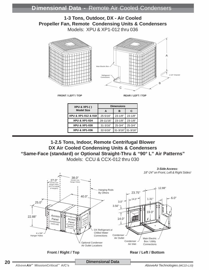
Dimensional Data - Remote Air Cooled Condensers
Dimensional Data
1-3 Tons, Outdoor, DX - Air CooledPropeller Fan, Remote Condensing Units & Condensers
Models: XPU & XP1-012 thru 036
1-2.5 Tons, Indoor, Remote Centrifugal BlowerDX Air Cooled Condensing Units & Condensers
“Same-Face (standard) or Optional Straight-Thru & “90° L” Air Patterns”Models: CCU & CCX-012 thru 030
REAR / LEFT / TOPFRONT / LEFT / TOP
A
1-1/2" Channel
Main Electric Box
RefrigerantConnections
BC
Rear / Left / Bottom
22.88"
25.0"
AccessPanel (compressor, cond coil)
AccessPanel(Condenser Blwr/Mtr)
40.0"
4 x 3/4"Hanger Holes
Front / Right / Top
27.0"(Center-Line
Hanger Holes;29.0" to Outside
of Hangers)
38.0"(Center-Line
Hanger Holes)
Hanging RodsBy Others
CondenserAir Inlet
12.88"
6.0"14.0"
23.75"
3.0"
14.0"
3.56"
1.31"
19.0"
CondenserAir Outlet
Access
Panel
(Cond
Blwr/Mtr)
Main ElectricBox / Utility
Connections
DX Refrigerant orChilled WaterConnections
Optional CondenserAir Outlet Locations
3-Side Access:18”-24” on Front, Left & Right Sides!
XPU & XP1-( )Model Size
Dimensions
A B C
XPU & XP1-012 & 018 25-5/16" 23-1/8" 23-1/8"
XPU & XP1-024 28-11/16" 23-1/8" 23-1/8"
XPU & XP1-030 31-3/16" 25-3/4" 25-3/4"
XPU & XP1-036 32-5/16" 31-3/16" 31-3/16"
AboveAir™ MissionCritical™ A/C’sAboveAir Technologies (MC22-L10)21
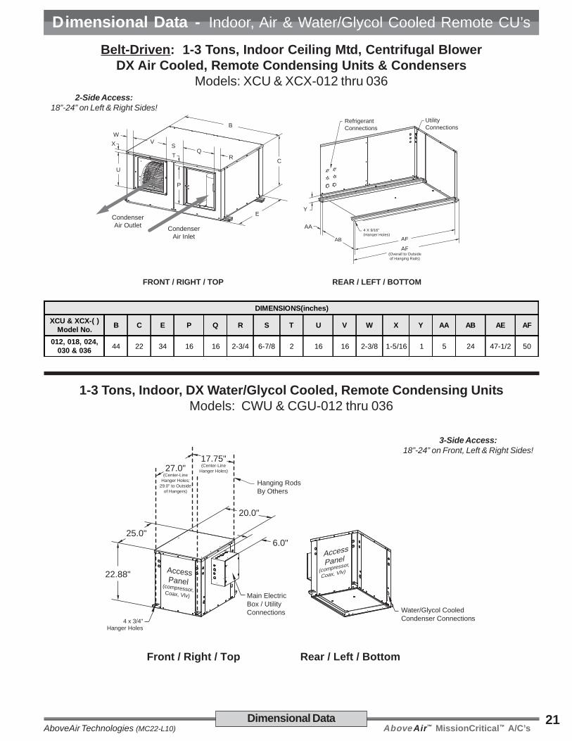
Dimensional Data - Indoor, Air & Water/Glycol Cooled Remote CU’s
Dimensional Data
U
X
P
T
VQ
S
R
W
CondenserAir Outlet Condenser
Air Inlet
FRONT / RIGHT / TOP
UtilityConnections
Y
AB AE
AA
REAR / LEFT / BOTTOM
4 X 9/16"(Hanger Holes)
AF(Overall to Outsideof Hanging Rails)
RefrigerantConnectionsB
C
E
Belt-Driven: 1-3 Tons, Indoor Ceiling Mtd, Centrifugal BlowerDX Air Cooled, Remote Condensing Units & Condensers
Models: XCU & XCX-012 thru 036
DIMENSIONS(inches)XCU & XCX-( )
Model No. B C E P Q R S T U V W X Y AA AB AE AF
012, 018, 024,030 & 036 44 22 34 16 16 2-3/4 6-7/8 2 16 16 2-3/8 1-5/16 1 5 24 47-1/2 50
2-Side Access:18”-24” on Left & Right Sides!
1-3 Tons, Indoor, DX Water/Glycol Cooled, Remote Condensing UnitsModels: CWU & CGU-012 thru 036
Rear / Left / Bottom
22.88"
25.0"
AccessPanel (compressor, Coax, Vlv)
20.0"
4 x 3/4"Hanger Holes
Front / Right / Top
27.0"(Center-Line
Hanger Holes;29.0" to Outside
of Hangers)
17.75"(Center-Line
Hanger Holes)
Hanging RodsBy Others
Water/Glycol CooledCondenser Connections
6.0"
Main ElectricBox / Utility Connections
AccessPanel
(compressor,
Coax, Vlv)
3-Side Access:18”-24” on Front, Left & Right Sides!
AboveAir™ MissionCritical™ A/C’s AboveAir Technologies (MC22-L10)22 Nomenclature / Ship Wts
Supplemental Data - Notes
Notes:____________________________________________________________________
____________________________________________________________________
____________________________________________________________________
____________________________________________________________________
____________________________________________________________________
____________________________________________________________________
____________________________________________________________________
____________________________________________________________________
____________________________________________________________________
____________________________________________________________________
____________________________________________________________________
____________________________________________________________________
____________________________________________________________________
____________________________________________________________________
____________________________________________________________________
____________________________________________________________________
____________________________________________________________________
____________________________________________________________________
____________________________________________________________________
____________________________________________________________________
AboveAir™ MissionCritical™ A/C’sAboveAir Technologies (MC22-L10)23Nomenclature / Ship Wts
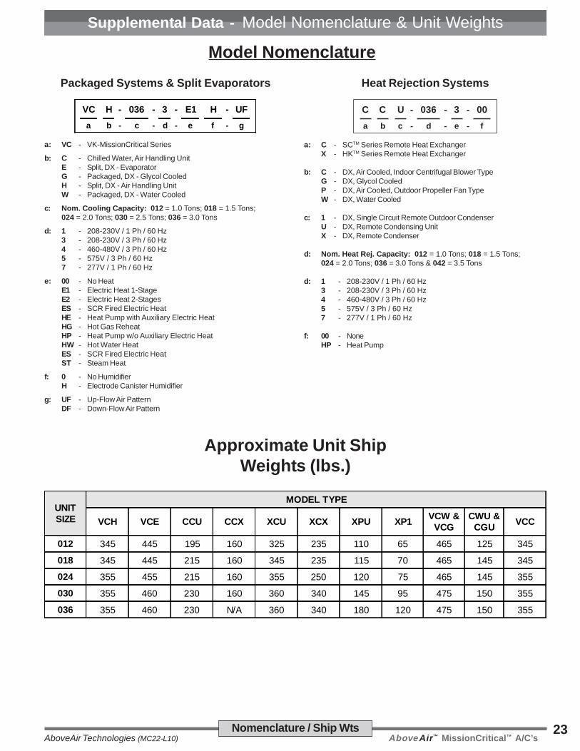
Supplemental Data - Model Nomenclature & Unit Weights
Model Nomenclature
Approximate Unit ShipWeights (lbs.)
UNITSIZE
MODEL TYPE
VCH VCE CCU CCX XCU XCX XPU XP1 VCW &VCG
CWU &CGU VCC
012 345 445 195 160 325 235 110 65 465 125 345
018 345 445 215 160 345 235 115 70 465 145 345
024 355 455 215 160 355 250 120 75 465 145 355
030 355 460 230 160 360 340 145 95 475 150 355
036 355 460 230 N/A 360 340 180 120 475 150 355
Packaged Systems & Split Evaporators
VC H - 036 - 3 - E1 H - UFa b - c - d - e f - g
a: VC - VK-MissionCritical Series
b: C - Chilled Water, Air Handling UnitE - Split, DX - EvaporatorG - Packaged, DX - Glycol CooledH - Split, DX - Air Handling UnitW - Packaged, DX - Water Cooled
c: Nom. Cooling Capacity: 012 = 1.0 Tons; 018 = 1.5 Tons;024 = 2.0 Tons; 030 = 2.5 Tons; 036 = 3.0 Tons
d: 1 - 208-230V / 1 Ph / 60 Hz3 - 208-230V / 3 Ph / 60 Hz4 - 460-480V / 3 Ph / 60 Hz5 - 575V / 3 Ph / 60 Hz7 - 277V / 1 Ph / 60 Hz
e: 00 - No HeatE1 - Electric Heat 1-StageE2 - Electric Heat 2-StagesES - SCR Fired Electric HeatHE - Heat Pump with Auxiliary Electric HeatHG - Hot Gas ReheatHP - Heat Pump w/o Auxiliary Electric HeatHW - Hot Water HeatES - SCR Fired Electric HeatST - Steam Heat
f: 0 - No HumidifierH - Electrode Canister Humidifier
g: UF - Up-Flow Air PatternDF - Down-Flow Air Pattern
Heat Rejection Systems
C C U - 630 - 3 - 00
a b c - d - e - f
a: C - SCTM Series Remote Heat ExchangerX - HKTM Series Remote Heat Exchanger
b: C - DX, Air Cooled, Indoor Centrifugal Blower TypeG - DX, Glycol CooledP - DX, Air Cooled, Outdoor Propeller Fan TypeW - DX, Water Cooled
c: 1 - DX, Single Circuit Remote Outdoor CondenserU - DX, Remote Condensing UnitX - DX, Remote Condenser
d: Nom. Heat Rej. Capacity: 012 = 1.0 Tons; 018 = 1.5 Tons;024 = 2.0 Tons; 036 = 3.0 Tons & 042 = 3.5 Tons
d: 1 - 208-230V / 1 Ph / 60 Hz3 - 208-230V / 3 Ph / 60 Hz4 - 460-480V / 3 Ph / 60 Hz5 - 575V / 3 Ph / 60 Hz7 - 277V / 1 Ph / 60 Hz
f: 00 - NoneHP - Heat Pump
AboveAir™ MissionCritical™ A/C’s AboveAir Technologies (MC22-L10)24
I n n o v a t i v e H VA C S o l u t i o n s
5179 Mountville RoadFrederick, Maryland 21703, U.S.A.
Phone: 301-874-1130, Facsimile: 301-874-1131
Email: [email protected]
Copyright 06/11Form: MC22-L10
Specifications are subjectto change without notice.
www.aaaaabobobobobovvvvveaireaireaireaireair.com
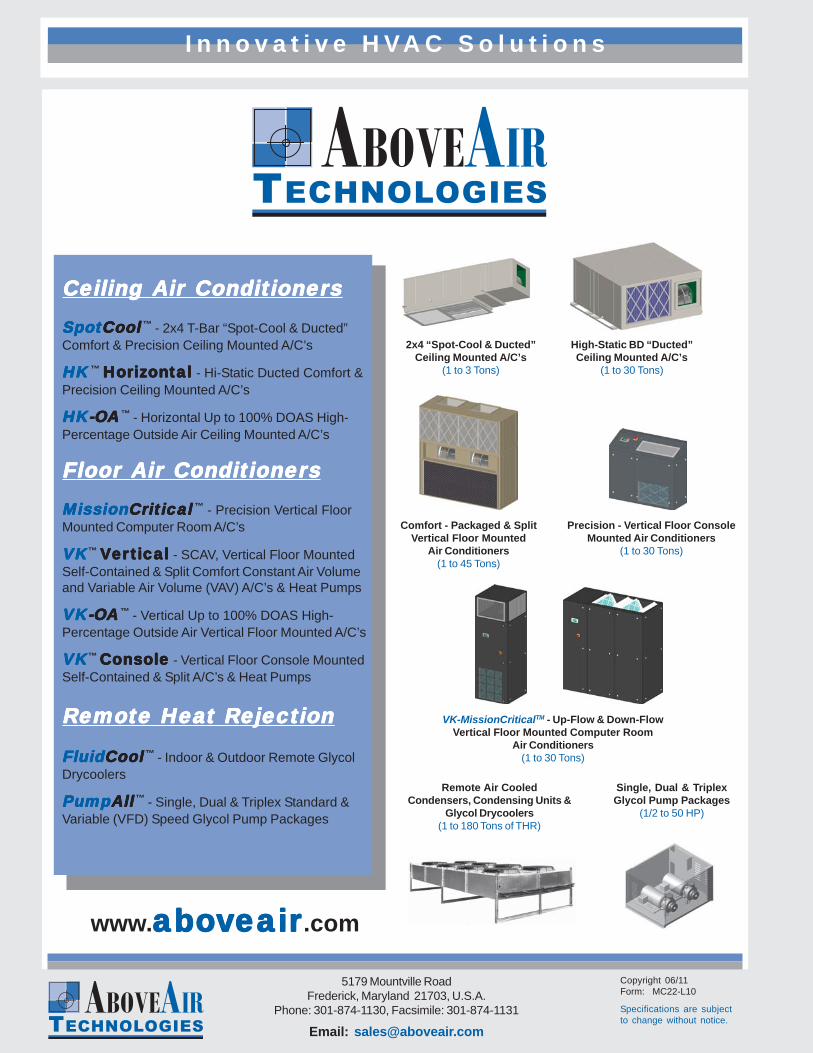
Comfort - Packaged & SplitVertical Floor Mounted
Air Conditioners(1 to 45 Tons)
VK-MissionCriticalTM - Up-Flow & Down-FlowVertical Floor Mounted Computer Room
Air Conditioners(1 to 30 Tons)
Remote Air CooledCondensers, Condensing Units &
Glycol Drycoolers(1 to 180 Tons of THR)
Precision - Vertical Floor ConsoleMounted Air Conditioners
(1 to 30 Tons)
High-Static BD “Ducted”Ceiling Mounted A/C’s
(1 to 30 Tons)
2x4 “Spot-Cool & Ducted”Ceiling Mounted A/C’s
(1 to 3 Tons)
Single, Dual & TriplexGlycol Pump Packages
(1/2 to 50 HP)
Ceiling Ceiling Ceiling Ceiling Ceiling Air ConditionerAir ConditionerAir ConditionerAir ConditionerAir ConditionersssssSpotSpotSpotSpotSpotCoolCoolCoolCoolCool
™ - 2x4 T-Bar “Spot-Cool & Ducted”Comfort & Precision Ceiling Mounted A/C’s
HKHKHKHKHK ™ HorizHorizHorizHorizHorizontalontalontalontalontal - Hi-Static Ducted Comfort &
Precision Ceiling Mounted A/C’s
HKHKHKHKHK-O-O-O-O-OAAAAA ™ - Horizontal Up to 100% DOAS High-
Percentage Outside Air Ceiling Mounted A/C’s
FFFFFloor loor loor loor loor Air ConditionerAir ConditionerAir ConditionerAir ConditionerAir ConditionersssssMissionMissionMissionMissionMissionCriticalCriticalCriticalCriticalCritical
™ - Precision Vertical FloorMounted Computer Room A/C’s
VKVKVKVKVK™ VVVVVerererererticalticalticalticaltical - SCAV, Vertical Floor MountedSelf-Contained & Split Comfort Constant Air Volumeand Variable Air Volume (VAV) A/C’s & Heat Pumps
VKVKVKVKVK-O-O-O-O-OAAAAA ™ - Vertical Up to 100% DOAS High-
Percentage Outside Air Vertical Floor Mounted A/C’s
VKVKVKVKVK™ ConsoleConsoleConsoleConsoleConsole - Vertical Floor Console MountedSelf-Contained & Split A/C’s & Heat Pumps
RRRRRemote Heaemote Heaemote Heaemote Heaemote Heat Rt Rt Rt Rt Rejectionejectionejectionejectionejection
FluidFluidFluidFluidFluidCoolCoolCoolCoolCool ™ - Indoor & Outdoor Remote Glycol
Drycoolers
PumpPumpPumpPumpPumpAllAllAllAllAll ™ - Single, Dual & Triplex Standard &
Variable (VFD) Speed Glycol Pump Packages