Embed Size (px)
Citation preview
PVDF chemical supply piping
Project Client project Document Rev. Page Pages
PVDF – chemical supply
piping report_e.rtf 0 1 22
Titel
Engineerging Services - Calculation report
Georg Fischer Piping Systems Ltd.
Xa
Ya
Za
12
3
5
13
910
687
1211
14
19
18171516
427262524
232221
2028
2930313233
34
4546
47
353736
39
40
42
43
3861
63
5960
4166
6465
44
68
4849
505152
5354555756
58
116117118
119113114115
67
79767877
8280
81
69
73
74
75
8485
8687
8994
919062
929388
112
110
111
70
71
72
839596
99
101
104
105106
97
98
103
102
100
109
107
108
120121
122
125
127
129130
131
135
136
137140139138
132
133
134
128
126141
142143
124
123
Client: GF USA
Created by: Georg Fischer Piping Systems Ltd. Ebnatstrasse 111
CH - 8201 Schaffhausen
Switzerland
Created: Approved by: Created by:
10/02/2017 Hanspeter Müller Sven Fuegner
Date: 2017-02-10
Page: 2 of 22
Contents
1 SCOPE OF WORK AND RESULTS ................................................................................................. 3
1.1 SCOPE OF WORK ............................................................................................................................................. 3 1.2 SUMMARY OF RESULTS .................................................................................................................................... 3
1.2.1 Stresses ................................................................................................................................................ 3
2 CALCULATION BASICS .................................................................................................................. 4
2.1 CALCULATION PROGRAM ................................................................................................................................. 4 2.2 CALCULATION RULE ......................................................................................................................................... 5 2.3 DRAWINGS AND DOCUMENTS ........................................................................................................................... 6
3 SYSTEM DESCRIPTION .................................................................................................................. 7
3.1 DIMENSIONS AND CALCULATION DATA: .............................................................................................................. 8 3.1.1 Pipe dimensions.................................................................................................................................... 8 3.1.2 Structural section dimensions ............................................................................................................... 8
3.2 LINE MASSES .................................................................................................................................................. 9 3.3 COMPONENTS ................................................................................................................................................. 9
4 LOAD CASES ................................................................................................................................ 10
4.1 OVERVIEW .................................................................................................................................................... 10 4.2 GLOBAL LOADS ............................................................................................................................................. 10 4.3 SPECIFIC LOADS OF LOAD CASES ................................................................................................................... 10
5 REMARKS AND CHANGES .......................................................................................................... 12
5.1 REMARKS ..................................................................................................................................................... 12 5.2 CHANGES ..................................................................................................................................................... 12
6 RESULTS ....................................................................................................................................... 13
6.1 STRESS EVALUATION VGLSR - VERGLEICHSSPANNUNGEN FÜR ROHRE ACC. TO VON MISES ............................ 13 6.2 STRESS EVALUATION VGLSR - VERGLEICHSSPANNUNGEN FÜR ROHRE, WITH RECOMMENDED SUPPORTS ......... 16 6.3 MOVEMENT OF VALVES ................................................................................................................................. 18 6.4 RECOMMENDATIONS ..................................................................................................................................... 19
7 APPENDIX ..................................................................................................................................... 22
Date: 2017-02-10
Page: 3 of 22
1 Scope of work and results
1.1 Scope of work
For the calculation system
PVDF chemical supply piping
a pipe stress calculation has been carried out, to evaluate the system with regard to dead load, thermal expansion and additional loads.
This calculation covers the analysis of:
flexibility of the pipe system geometry
stresses in pipes and fittings
pipe displacement
pipe deformations
loads on components
loads on supports
1.2 Summary of results
1.2.1 Stresses
In consideration of the assumptions mentioned in this report the calculations result in 286.2% maximum stress overrun.
In consideration of the changes mentioned in this report the calculations result in no stress overrun.
Date: 2017-02-10
Page: 4 of 22
2 Calculation Basics
2.1 Calculation program
The pipe stresses have been calculated using the program ROHR2, rev. 32.0.
A detailed description of both, the theoretical aspects and its practical application is given in the ROHR2-manual. The program provides solutions for static and dynamic analysis of 3-D pipe systems and gene-ral framework structures.
Date: 2017-02-10
Page: 5 of 22
2.2 Calculation rule
The calculation was carried out acc. to VGLSR - Vergleichsspannungen für Rohre.
According to EN ISO 12162 Georg Fischer Piping Systems recommends the following safety factors C:
Cmin for industrial applications is 1.6.
Cmin for water applications is 1.25.
Thermoplastic Piping Systems Cmin
ABS 1.8
PE 100 1.6
PP-H 2.0
PVC-U + PVC-C 2.5
PVDF 2.0
PB 1.5
Georg Fischer Piping Systems is following the technical code DVS 2210-1 rev. April 1997 for planning and execution of above-ground Pipe Systems. This standard covers industrial pipelines made of Thermoplastics in metric standard. DVS 2210-1 refers to the following further applicable documents:
- DIN 8077 - DVS 2205-1 - DVS 2205-2 - AD-B9
- DIN 4279-8 - DIN 4279-9 - DIN 4279-10 - DIN 8061 with suppl.
- DIN 8062 - DIN 8063 ff. - DIN 8074 - 8075 with suppl.
- DIN 8076 ff. - DIN 8077 - DIN 8078 with suppl. - DIN 8079
- DIN 8080 - DIN EN ISO 9000 - 9004 - DIN EN 10204 - DIN 16450
- DIN 16887 - DIN 16888 ff. - DIN 16928 - DIN 16960
- DIN 16962 ff. - DIN 16963 ff. - DIN 18200 - DIN 32502
- DIN 53457 - DVS 2201-2 - DVS 2203-1 - DVS 2203-2
- DVS 2203-3 - DVS 2203-4 - DVS 2203-5 - DVS 2204-1
- DVS 2204-2 - DVS 2205-1 - DVS 2207-1 - DVS 2207-3
- DVS 2207-3 suppl. - DVS 2207-4 - DVS 2207-4 suppl. - DVS 2207-11
- DVS 2207-15 - DVS 2208-1 - DVS 2208-2 - DVS 2209-1
- DVS 2212-1 - DVS 2212-2 - DVS 2213 - DVS 2221-1
- DIN EN 1778 - DIN 1910-1 - DIN 2401-1 - DIN 2402
- DIN 2403 - DIN 2501-1 - DIN 3441 ff. - DIN 3441-4
- DIN 3442 ff. - DIN 3535-3 - DIN 3543-3 - DIN 3543-4
- DIN 3544-1 - DIN 4102 ff. - DIN 4279-1 - DIN V 4279-1
Date: 2017-02-10
Page: 6 of 22
2.3 Drawings and documents
This calculation is based on the following documents:
Isometrics
Date: 2017-02-10
Page: 7 of 22
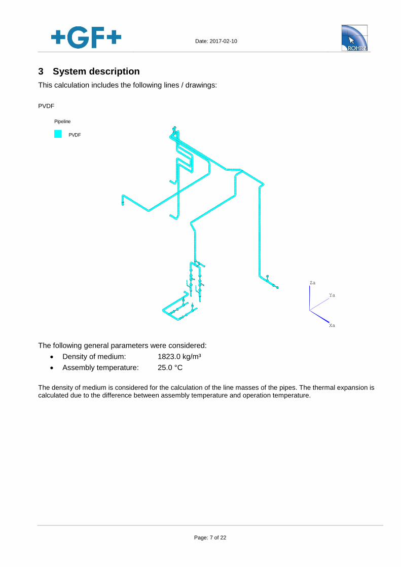
3 System description
This calculation includes the following lines / drawings:
PVDF
Xa
Ya
Za
Pipeline
PVDF
The following general parameters were considered:
Density of medium: 1823.0 kg/m³
Assembly temperature: 25.0 °C
The density of medium is considered for the calculation of the line masses of the pipes. The thermal expansion is calculated due to the difference between assembly temperature and operation temperature.
Date: 2017-02-10
Page: 8 of 22
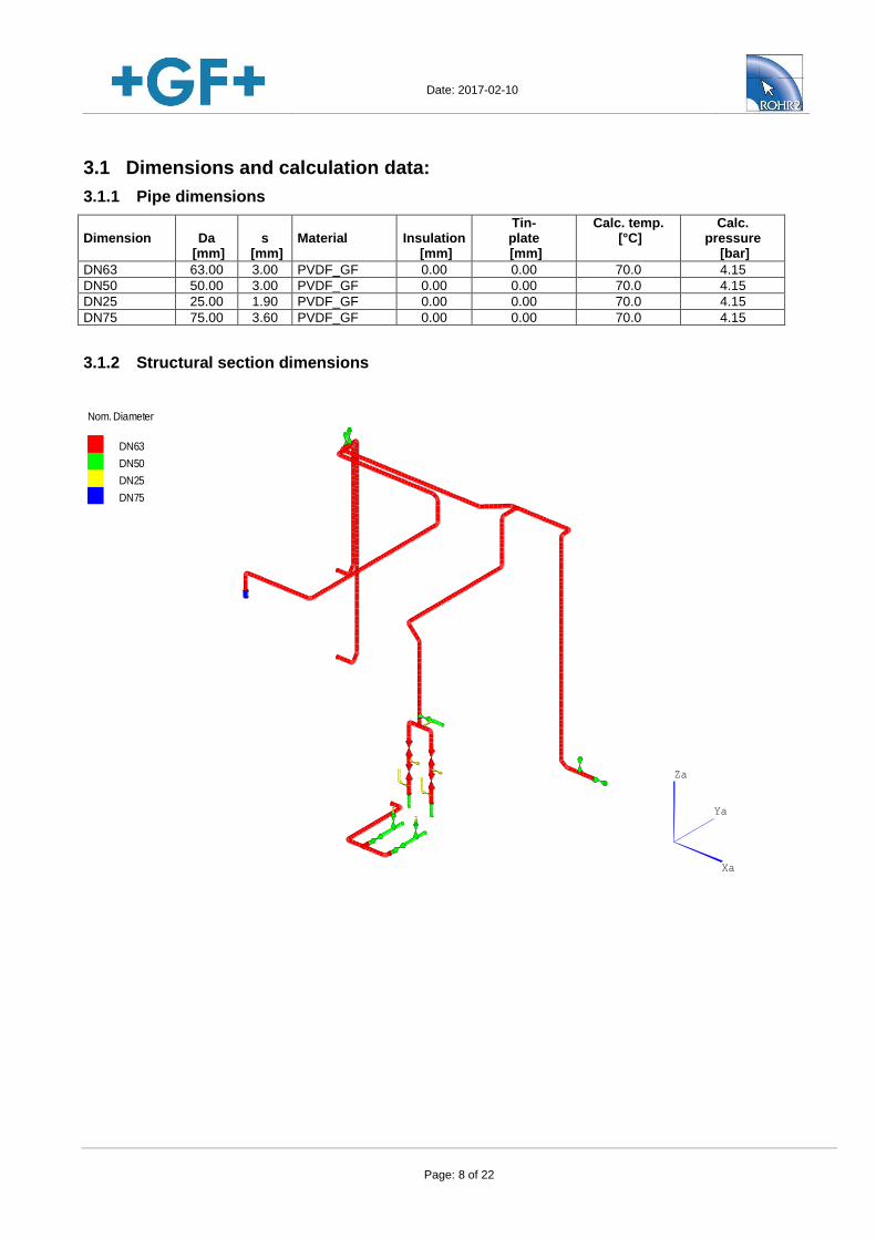
3.1 Dimensions and calculation data:
3.1.1 Pipe dimensions
Dimension
Da
[mm]
s
[mm]
Material
Insulation
[mm]
Tin- plate [mm]
Calc. temp. [°C]
Calc. pressure
[bar]
DN63 63.00 3.00 PVDF_GF 0.00 0.00 70.0 4.15
DN50 50.00 3.00 PVDF_GF 0.00 0.00 70.0 4.15
DN25 25.00 1.90 PVDF_GF 0.00 0.00 70.0 4.15
DN75 75.00 3.60 PVDF_GF 0.00 0.00 70.0 4.15
3.1.2 Structural section dimensions
Xa
Ya
Za
Nom. Diameter
DN75
DN25
DN50
DN63
Date: 2017-02-10
Page: 9 of 22
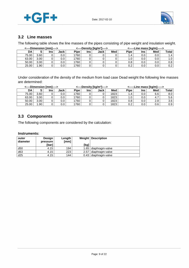
3.2 Line masses
The following table shows the line masses of the pipes consisting of pipe weight and insulation weight.
<----Dimension [mm]----> <----Density [kg/m³]----> <-----Line mass [kg/m]----->
DA S Ins Jack Pipe Ins Jack Med Pipe Ins Med Total
75.00 3.60 0 0.0 1760 0 0 0 1.4 0.0 0.0 1.4
63.00 3.00 0 0.0 1760 0 0 0 1.0 0.0 0.0 1.0
50.00 3.00 0 0.0 1760 0 0 0 0.8 0.0 0.0 0.8
25.00 1.90 0 0.0 1760 0 0 0 0.2 0.0 0.0 0.2
Under consideration of the density of the medium from load case Dead weight the following line masses
are determined:
<----Dimension [mm]----> <----Density [kg/m³]----> <-----Line mass [kg/m]----->
DA S Ins Jack Pipe Ins Jack Med Pipe Ins Med Total
75.00 3.60 0 0.0 1760 0 0 1823 1.4 0.0 6.6 8.0
63.00 3.00 0 0.0 1760 0 0 1823 1.0 0.0 4.7 5.6
50.00 3.00 0 0.0 1760 0 0 1823 0.8 0.0 2.8 3.6
25.00 1.90 0 0.0 1760 0 0 1823 0.2 0.0 0.6 0.9
3.3 Components
The following components are considered by the calculation:
Instruments:
outer diameter
Design pressure
[bar]
Length [mm]
Weight
[kg]
Description
d50 4.15 194 1.65 diaphragm-valve
d63 4.15 223 2.57 diaphragm-valve
d25 4.15 144 0.43 diaphragm-valve
Date: 2017-02-10
Page: 10 of 22
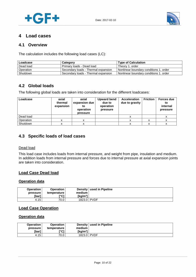
4 Load cases
4.1 Overview
The calculation includes the following load cases (LC):
Loadcase Category Type of Calculation
Dead load Primary loads - Dead load Theory 1. order
Operation Secondary loads - Thermal expansion Nonlinear boundary conditions 1. order
Shutdown Secondary loads - Thermal expansion Nonlinear boundary conditions 1. order
4.2 Global loads
The following global loads are taken into consideration for the different loadcases:
Loadcase axial thermal
expansion
axial expansion due
to operation pressure
Upward bend due to
operation pressure
Acceleration due to gravity
Friction Forces due to
internal pressure
Dead load x x
Operation x x x x x
Shutdown x x x x x
4.3 Specific loads of load cases
Dead load
This load case includes loads from internal pressure, and weight from pipe, insulation and medium. In addition loads from internal pressure and forces due to internal pressure at axial expansion joints are taken into consideration.
Load Case Dead load
Operation data
Operation pressure
[bar]
Operation temperature
[°C]
Density medium [kg/m³]
used in Pipeline
4.15 70.0 1823.0 PVDF
Load Case Operation
Operation data
Operation pressure
[bar]
Operation temperature
[°C]
Density medium [kg/m³]
used in Pipeline
4.15 70.0 1823.0 PVDF
Date: 2017-02-10
Page: 11 of 22
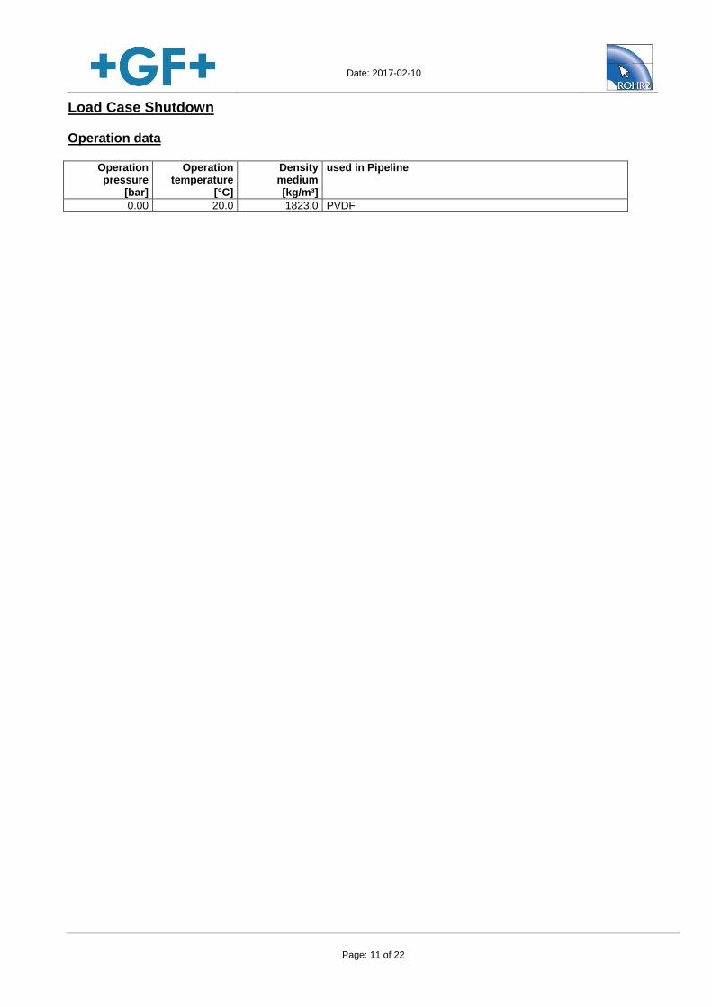
Load Case Shutdown
Operation data
Operation pressure
[bar]
Operation temperature
[°C]
Density medium [kg/m³]
used in Pipeline
0.00 20.0 1823.0 PVDF
Date: 2017-02-10
Page: 12 of 22
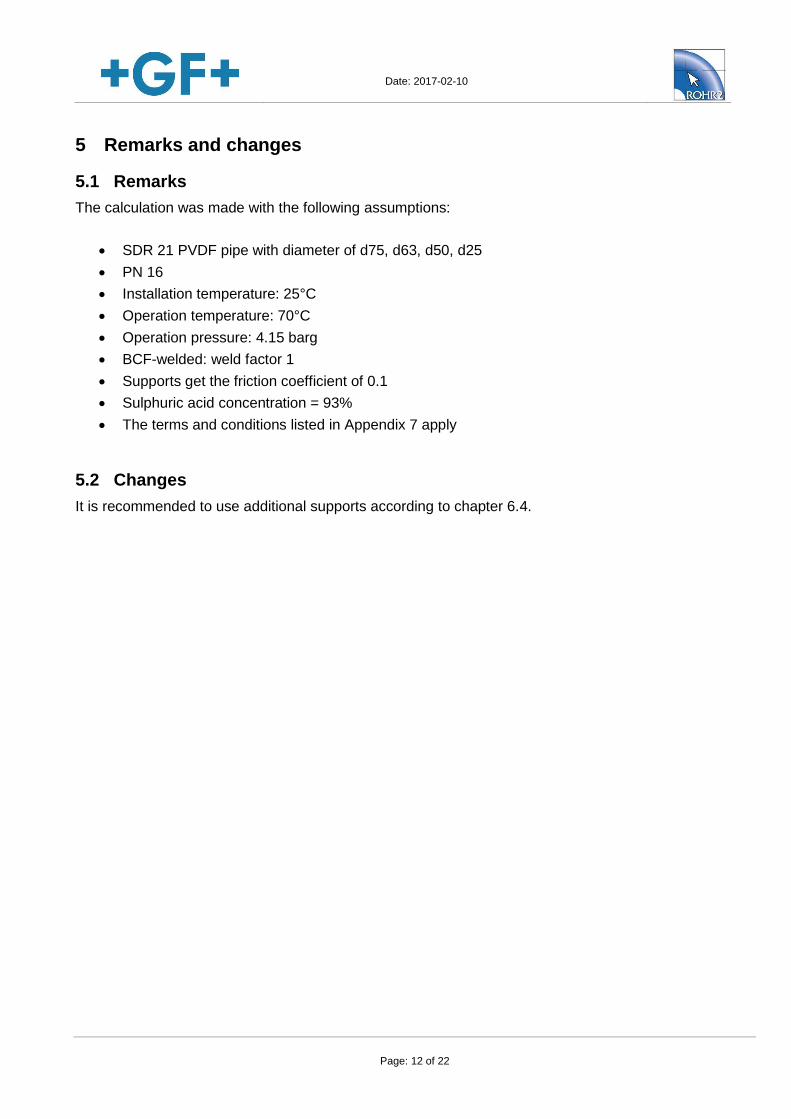
5 Remarks and changes
5.1 Remarks
The calculation was made with the following assumptions:
SDR 21 PVDF pipe with diameter of d75, d63, d50, d25
PN 16
Installation temperature: 25°C
Operation temperature: 70°C
Operation pressure: 4.15 barg
BCF-welded: weld factor 1
Supports get the friction coefficient of 0.1
Sulphuric acid concentration = 93%
The terms and conditions listed in Appendix 7 apply
5.2 Changes
It is recommended to use additional supports according to chapter 6.4.
Date: 2017-02-10
Page: 13 of 22
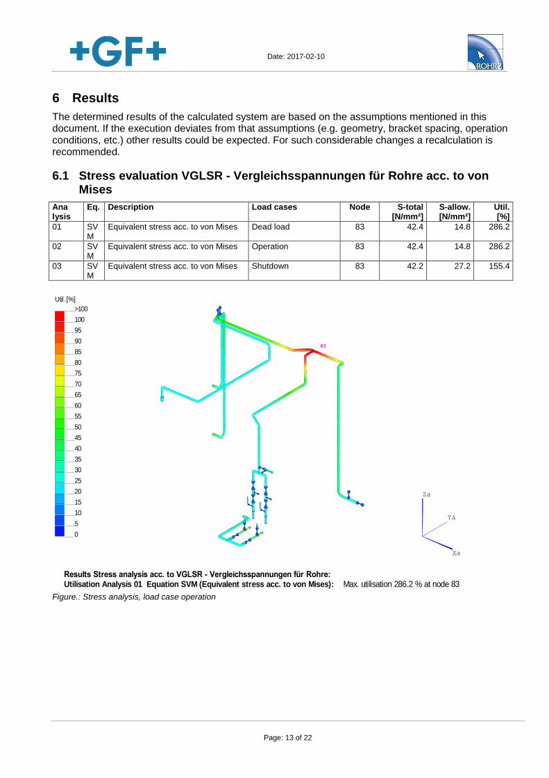
6 Results
The determined results of the calculated system are based on the assumptions mentioned in this document. If the execution deviates from that assumptions (e.g. geometry, bracket spacing, operation conditions, etc.) other results could be expected. For such considerable changes a recalculation is recommended.
6.1 Stress evaluation VGLSR - Vergleichsspannungen für Rohre acc. to von Mises
Ana lysis
Eq. Description Load cases Node S-total [N/mm²]
S-allow. [N/mm²]
Util. [%]
01 SVM
Equivalent stress acc. to von Mises Dead load 83 42.4 14.8 286.2
02 SVM
Equivalent stress acc. to von Mises Operation 83 42.4 14.8 286.2
03 SVM
Equivalent stress acc. to von Mises Shutdown 83 42.2 27.2 155.4
Results Stress analysis acc. to VGLSR - Vergleichsspannungen für Rohre:Utilisation Analysis 01 Equation SVM (Equivalent stress acc. to von Mises): Max. utilisation 286.2 % at node 83
Xa
Ya
Za
Util. [%]
0
5
10
15
20
25
30
35
40
45
50
55
60
65
70
75
80
85
90
95
100
>100
83
Figure.: Stress analysis, load case operation
Date: 2017-02-10
Page: 14 of 22
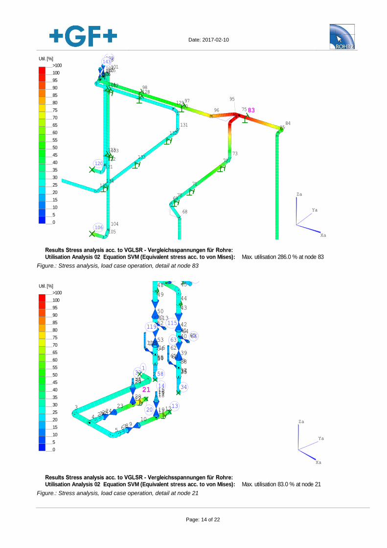
Results Stress analysis acc. to VGLSR - Vergleichsspannungen für Rohre:Utilisation Analysis 02 Equation SVM (Equivalent stress acc. to von Mises): Max. utilisation 286.0 % at node 83
Xa
Ya
Za
Util. [%]
0
5
10
15
20
25
30
35
40
45
50
55
60
65
70
75
80
85
90
95
100
>100
68
69
73
74
75
8485
70
71
72
83
95
96
99
101
104
105106
97
98
103
102
100
109
107
108
120121
122
125
127
129130
131
135
132
133
134
128
126141
142143
124
123
Figure.: Stress analysis, load case operation, detail at node 83
Results Stress analysis acc. to VGLSR - Vergleichsspannungen für Rohre:Utilisation Analysis 02 Equation SVM (Equivalent stress acc. to von Mises): Max. utilisation 83.0 % at node 21
Xa
Ya
Za
Util. [%]
0
5
10
15
20
25
30
35
40
45
50
55
60
65
70
75
80
85
90
95
100
>100
12
3
5
13
910
687
1211
14
19
18171516
4272625
2423
22
21
20
28
2930313233
34
45
46
353736
39
40
42
43
3861
63
5960
4166
6465
44
48
49
505152
53
54
555756
58
116117118
119
113114115
798281
62
Figure.: Stress analysis, load case operation, detail at node 21
Date: 2017-02-10
Page: 15 of 22
For the lifetime independent equations the allowable loads were determined, based on 7000 load cycles.
The calculation of the allowable and calculated stresses are listed in ROHR2 output ”Stresses”.
According to chapter 2.2 a minimum Safety-Factor of 1.6 is required (industry application).
Additionally a chemical reduction-ratio of 1.3 for usage of PVDF with sulphuric acid at 70°C has to be applied accordingly to the chemical resistance table of Georg Fischer Piping Systems.
Therefore a safety factor of 1.6 * 1.3 = 2.08 is required
The maximum ratio of the system of Szul/Sges = 14.8 / 42.4 = 0.4 is at node 83 and 14.8 / 12.3 = 1.2 at node 21.
The determined Safety-Factor does not meet Georg Fischer Piping Systems’ requirements.
Date: 2017-02-10
Page: 16 of 22
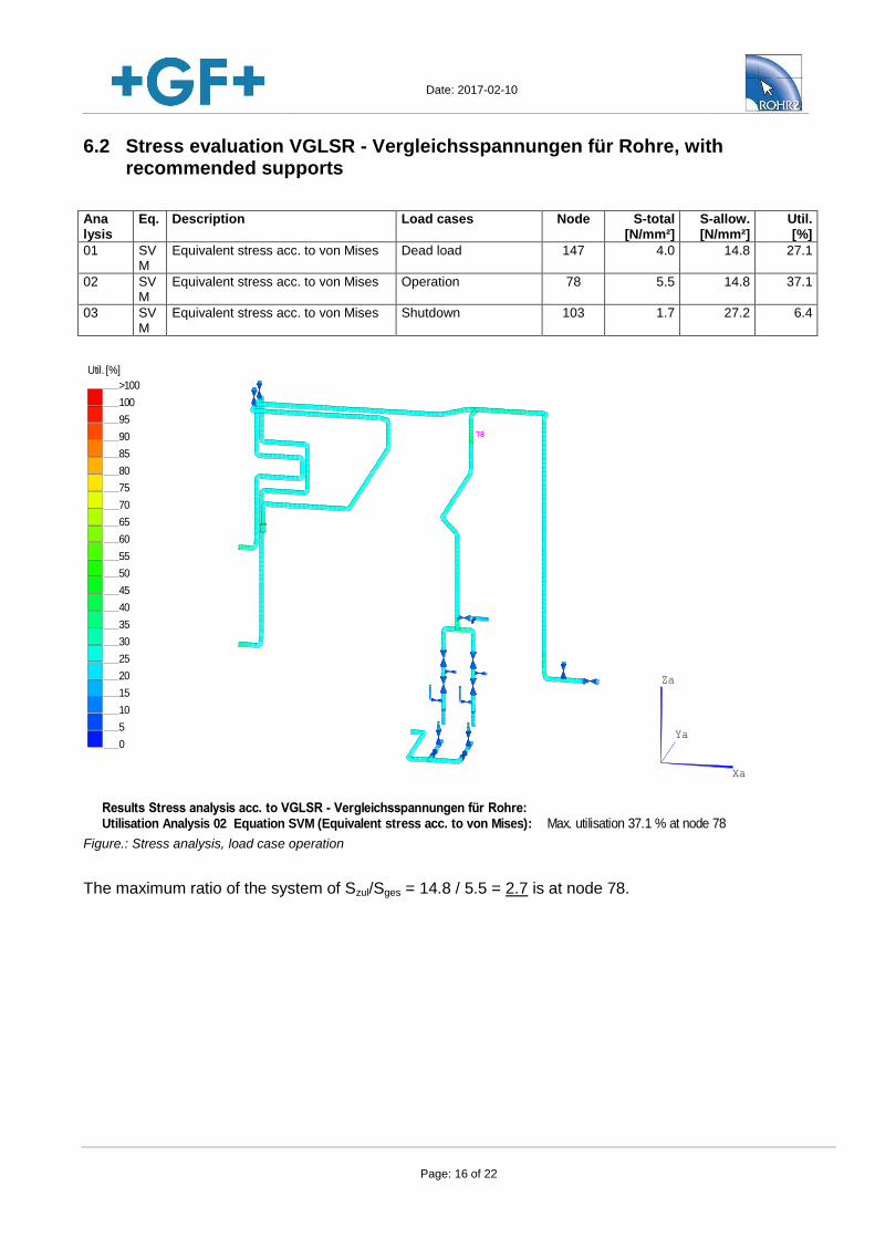
6.2 Stress evaluation VGLSR - Vergleichsspannungen für Rohre, with recommended supports
Ana lysis
Eq. Description Load cases Node S-total [N/mm²]
S-allow. [N/mm²]
Util. [%]
01 SVM
Equivalent stress acc. to von Mises Dead load 147 4.0 14.8 27.1
02 SVM
Equivalent stress acc. to von Mises Operation 78 5.5 14.8 37.1
03 SVM
Equivalent stress acc. to von Mises Shutdown 103 1.7 27.2 6.4
Results Stress analysis acc. to VGLSR - Vergleichsspannungen für Rohre:Utilisation Analysis 02 Equation SVM (Equivalent stress acc. to von Mises): Max. utilisation 37.1 % at node 78
Xa
Ya
Za
Util. [%]
0
5
10
15
20
25
30
35
40
45
50
55
60
65
70
75
80
85
90
95
100
>100
78
Figure.: Stress analysis, load case operation
The maximum ratio of the system of Szul/Sges = 14.8 / 5.5 = 2.7 is at node 78.
Date: 2017-02-10
Page: 17 of 22
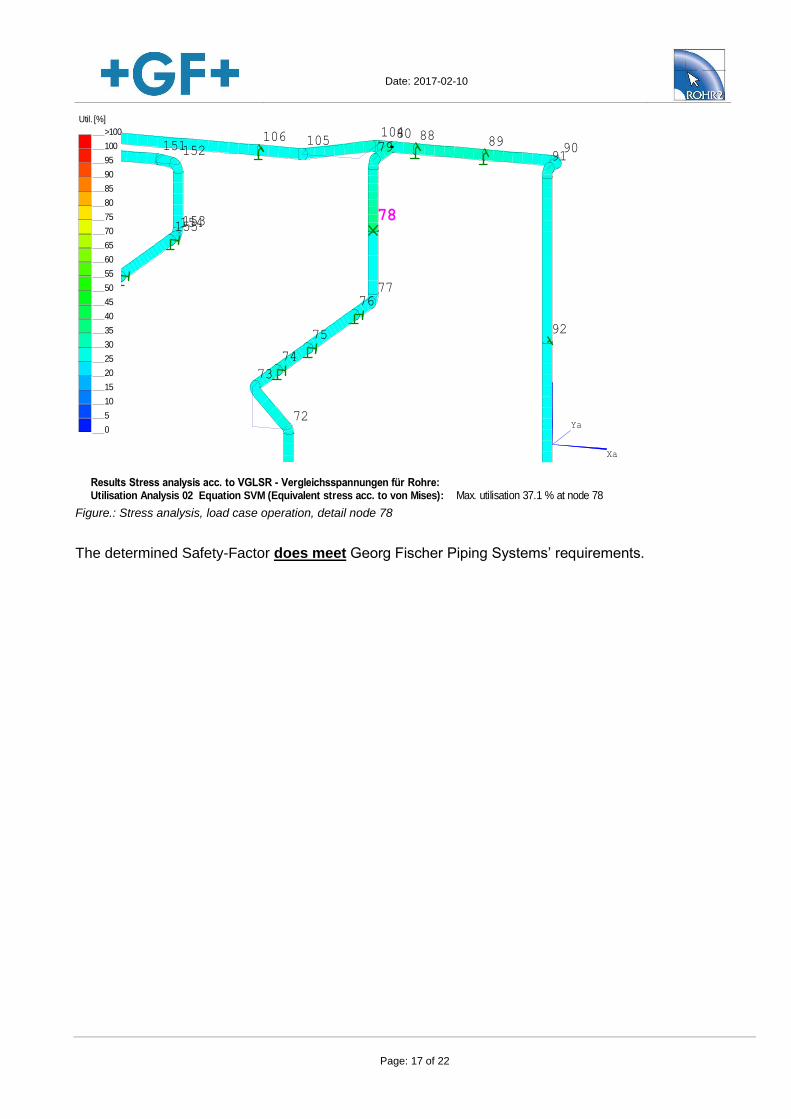
Results Stress analysis acc. to VGLSR - Vergleichsspannungen für Rohre:Utilisation Analysis 02 Equation SVM (Equivalent stress acc. to von Mises): Max. utilisation 37.1 % at node 78
Xa
Ya
Za
Util. [%]
0
5
10
15
20
25
30
35
40
45
50
55
60
65
70
75
80
85
90
95
100
>100
72
73
77
7980
9091
74
75
76
104105106
151152
88
78
89
153154155
92
Figure.: Stress analysis, load case operation, detail node 78
The determined Safety-Factor does meet Georg Fischer Piping Systems’ requirements.
Date: 2017-02-10
Page: 18 of 22
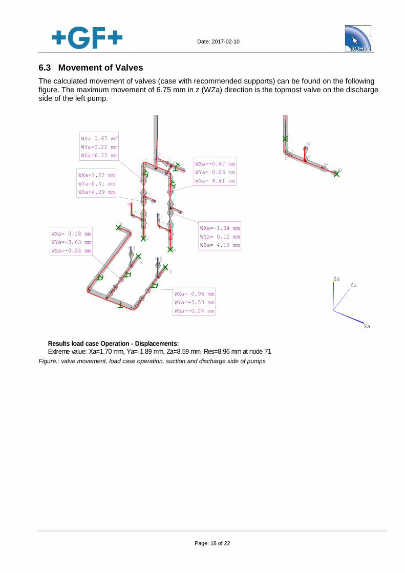
6.3 Movement of Valves
The calculated movement of valves (case with recommended supports) can be found on the following figure. The maximum movement of 6.75 mm in z (WZa) direction is the topmost valve on the discharge side of the left pump.
Results load case Operation - Displacements: Extreme value: Xa=1.70 mm, Ya=-1.89 mm, Za=8.59 mm, Res=8.96 mm at node 71
Xa
YaZa
WXa=0.67 mm
WYa=0.22 mm
WZa=6.75 mm
WXa=-0.67 mm
WYa= 0.06 mm
WZa= 6.61 mm
WXa=-1.34 mm
WYa= 0.12 mm
WZa= 4.19 mm
WXa=1.22 mm
WYa=0.41 mm
WZa=4.29 mm
WXa= 0.96 mm
WYa=-3.53 mm
WZa=-0.24 mm
WXa= 0.18 mm
WYa=-3.63 mm
WZa=-0.24 mm
1
2
9
17
13
14
10
12
11
16
18
23
2221
1920
7
313029
28
27
25 24
32
33343536
37
38
49
50
51
394140
43
44
46
47
42
65
67
63
64
45
70
68
69
48
52
53
54
55
56
57
58
596160
62
132
133134
135
129
130
131
71
84
81
83
82
87
85
86
95
96
98
103
10099
66
101
102
97
128
126
127
26
15
4
65
3
94
8
Figure.: valve movement, load case operation, suction and discharge side of pumps
Date: 2017-02-10
Page: 19 of 22
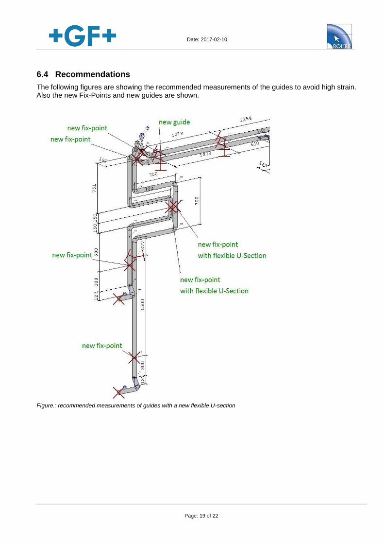
6.4 Recommendations
The following figures are showing the recommended measurements of the guides to avoid high strain. Also the new Fix-Points and new guides are shown.
Figure.: recommended measurements of guides with a new flexible U-section
Date: 2017-02-10
Page: 20 of 22
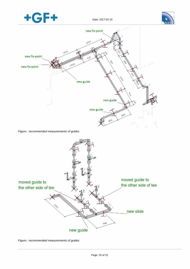
Figure.: recommended measurements of guides
Figure.: recommended measurements of guides
Date: 2017-02-10
Page: 21 of 22
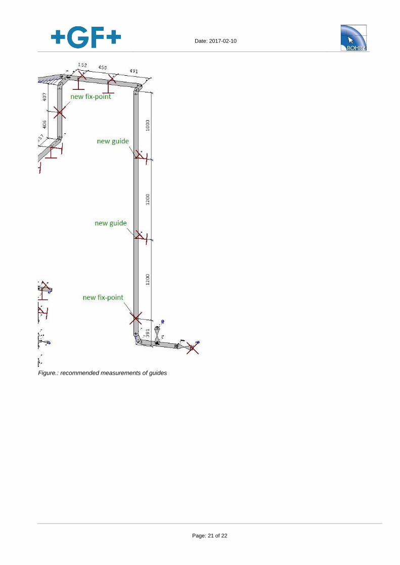
Figure.: recommended measurements of guides
Date: 2017-02-10
Page: 22 of 22
7 Appendix
System plots and detail plots
Load cases
Stresses
Loads on supports
Detail deflection table and figures
By using this report the following terms and conditions are accepted:
All statements and information contained in this report (incl. any attachments) only apply, unless otherwise indicated expressly, to products and systems of Georg Fischer Piping Systems Ltd.*, and are valid subject to the correctness and completeness of the information given by the user. In no case whatsoever shall the user be entitled to claim damages other than compensation for costs arisen for these products themselves (e.g. claims for loss of profit and other direct or indirect damages). Planning, designs and installations may only be performed by qualified specialists.
This report (incl. any attachments) is confidential and exclusively for the person addressed or its representative. Please note that any form of unauthorized use, publication, reproduction, copying or disclosure of the content of this report is not permitted.
*Georg Fischer Piping Systems Ltd. means any entity directly or indirectly controlled by Georg Fischer AG, Switzerland, and functionally belonging to the division Georg Fischer Piping Systems.