Embed Size (px)
Citation preview

Xxx/xxx P:\Kaiser\Waterpark 1\2012-263 Water Park 1TER Expansion & Fire Pump Add\Sup\Docs\Submittals\2012-262 SEC 253213 263600 TRK 13.2393 (WTC) 8-29-13.doc Cator, Ruma & Associates, Co. Disclosure: Checking is only for general conformance with the design concept of the project and general compliance with the information given in the contract documents. Any action shown is subject to the requirements of the plans and specifications. Contractor is responsible for dimensions that shall be confirmed and correlated at the job sites; fabrication process and techniques of construction; coordination of their work with that of all other trades, and the satisfactory performance of their work.
Engineering Solutions Since 1959 Mechanical o Electrical o Plumbing o Technology o Architectural Lighting o Commissioning
Page 1 of 1
Construction Shop Drawings Transmittal Date 8/29/13
To: RNL
Attn: SHEL BARRY
Project: KAISER WATERPARK TER
Cator, Ruma & Assoc. Project No.: 2012-263
Cator, Ruma & Assoc. Tracking No: 13.2393
NOTE: The Engineer’s review of these shop drawings does not relieve the Contractor of his responsibility to comply with drawings or specifications. Any deviation from specified equipment or material must be called to the Engineer’s attention in writing at the time of submission. The Contractor must secure written acceptance for said deviations.
Item & Section Number
Copies*
Manufacturer
No
Exception
Taken
Make
Corrections
Noted
Rejected
Revise
And
Resubmit
Submit
Specified
Item
GENERATOR 263213 1 ONAN X
TRANSFER SWITCHES 263600
1 ONAN X
Remarks: See attached review commentsSee attached review commentsSee attached review commentsSee attached review comments
* We have retained one copy of each of the above items for our records. CATOR, RUMA & ASSOCIATES, CO.
BILL CARPENTER

Xxx/xxx P:\Kaiser\Waterpark 1\2012-263 Water Park 1TER Expansion & Fire Pump Add\Sup\Docs\Submittals\2012-262 SEC 253213 263600 TRK 13.2393 (WTC) 8-29-13.doc Cator, Ruma & Associates, Co. Disclosure: Checking is only for general conformance with the design concept of the project and general compliance with the information given in the contract documents. Any action shown is subject to the requirements of the plans and specifications. Contractor is responsible for dimensions that shall be confirmed and correlated at the job sites; fabrication process and techniques of construction; coordination of their work with that of all other trades, and the satisfactory performance of their work.
Engineering Solutions Since 1959 Mechanical o Electrical o Plumbing o Technology o Architectural Lighting o Commissioning
PROJECT NAME: PROJECT NO:
TRACKING NO: DATE:
MECHANICAL/ELECTRICAL SUBMITTAL REVIEW COMMENTS

* Submittal Transmittal
10350 East Dakota Avenue
Denver, CO 80247
Kaiser Permanente Waterpark
Fax: Telephone: August 12, 2013
[For Reviewer]Project # 130858
Date: Transmittal No: 00038/12/13
Transmitted To: Transmitted By: Ian DarnellShel Barry
Turner Construction Co.RNL
1050 17th Street, Ste. A200,
Denver, CO 80265
Tel: 303.575.8495
Fax:
1819 Wazee Street, 2nd Floor
Denver, CO 80202
Tel:
Fax:
Submittal Package No Description Due Date
Generator and Transfer Switch0003 - 260000 - 0 8/16/13
Notes
Item Action
DescriptionQty TypeSpec Item # Rev AP AN RR RJ
Sub
SectionItem
0001 Generator Product DataProduct Data / Cut
Sheet
26 32 13 00105 01.2
0002 Generator ChecklistMatl's List26 32 13 00106 01.2
0003 Generator Shop DrawingsShop Drawings26 32 13 00107 01.2
0004 Transfer Switches Product DataProduct Data / Cut
Sheet
26 36 00 00121 01.2
0005 Transfer Switches Shop DrawingsShop Drawings26 36 00 00122 01.2
0006 Transfer Switches ChecklistMatl's List26 36 00 00123 01.2
0007 Generator Engine Horsepower
Curves, content &
capacity of exhaust
emission, de-rating
calculations,
harmonic analysis
Calculations26 32 13 00111 01.2
AP=Approved
AN=Approved as noted
RR=Revise and resubmit
RJ=Rejected
Contact Name Copies NotesCompany NameCc: Fax Number
Cator Ruma Gerald O'Brien 1
Cator Ruma Submittals Submittals 1
Kaiser Permanente Tony Barranco 1
Turner Construction Co. Aaron Laird 1
Turner Construction Co. Ian Darnell 1
Turner Construction Co. Wesley Sramek 1
Remarks
Signature Signed Date
TCCO - Submittal Transmittal - For Reviewer_V4xi.rpt Turner Construction Co.
RPT Revised: 5/23/12 Page 1 of 1

Kaiser Permanente Waterpark I – TER Expansion LEI Project No.: 113012
Submittal #113012.01
Division 26 Electrical
OWNER
GENERAL CONTRACTOR Turner Construction Company 1819 Wazee Street, 2nd Floor
Denver, CO 80202
ARCHITECT OF RECORD RNL
1050 17th Street, Suite A200 Denver, CO 80265
ELECTRICAL ENGINEER
Cator Ruma 896 Tabor Street
Lakewood, CO 80401
ELECTRICAL CONTRACTOR LEI Companies, Inc. 2017 Curtis Street
Denver, CO 80205
August 8, 2013

TABLE OF CONTENTS
SUBMITTAL SECTION DESCRIPTION SPEC SECTION
1 Engine Generator 26.32.13 & Transfer Switch Package 26.36.00
Submittal Comment and Review

Turner Construction Company
Reviewed Reviewed as noted Rejected Revise & Resubmit
THIS SUBMITTAL HAS BEEN REVIEWED FOR GENERAL CONFORMANCE AND COMPLIANCE WITH THE DESIGN CONCEPT AND CONTRACT DOCUMENTS. APPROVAL DOES NOT RELIEVE THE SUBCONTRACTOR FROM COMPLIANCE WITH THE PLANS, SPECIFICATIONS AND QUALITY STANDARDS SET FORTH IN THE CONTRACT DOCUMENTS NOR DOES IT RELIEVE RESPONSIBILITY FOR FIELD VERIFICATION OF ALL CONDITIONS RELATING TO THE SUBCONTRACTOR’S WORK. SUBCONTRACTOR IS RESPONSIBLE FOR DIMENSIONS AND QUANITIES OF MATERIALS RELATING TO THEIR WORK. THIS REVIEW DOES NOT AUTHORIZE SUBSTITUTIONS OR LIMITATIONS UNLESS SPECIFICALLY APPROVED AS SUCH.
Date: 8/8/13 Reviewed By:
RNL Cator Ruma


Power Generation Division
8211 East 96th Avenue Henderson, CO 80640
Kaiser Permanente Waterpark LEI Companies
Submittal #1 08/07/13
800kW Generator 125 & 800 Amp Automatic Transfer Switches
Sales Representative: Brian Taylor Phone #: 303-927-2248 Email: [email protected]

This Page Left Intentionally Blank

Line Qty. Part Number12 1 Genset-Diesel,60Hz,800kW 800DQCC3 Duty Rating-Standby Power A331-24 Listing-UL 2200 L090-25 EmissionCert,EPA,Tier 2,NSPS CI Stationary Emergency L170-26 Voltage-277/480,3 Phase,Wye,4 Wire R002-27 Alternator-60Hz, Wye, 480 Volts, 105C (S) B280-28 SET CONTROL-PCC 2100 H643-29 Display Language-English H536-210 Display-Control,Graphical H605-211 Alarm-Audible, Engine Shutdown KA08-212 Interface-CommunicationsNtwk,FTT-10 KP60-213 Meters-AC Output,Analog H606-214 Relays-Genset Status, User Configured K631-215 Control Mounting-Front Facing H679-216 Separator-Fuel/Water C127-217 Engine Cooling-Radiator, 50C Ambient E074-218 Shutdown-Low Coolant Level H389-219 Coolant Heater-208/240/480V, Below 40F Ambient Temp H557-220 Engine Air Cleaner-Normal Duty D041-221 Genset warranty- Base, Standby 2 years / 400 hours, Prime Power 1 ye L028-222 Literature-English L050-223 Packing-None A358-224 Common Parts Listing CP01-225 Product Revision - H SPEC-H2627282930313233343536
125 & 800 Amp Automatic Transfer Switches
Bill of Materials
LEI CompaniesCRM Project #65125, Revision # 0, Date: 08/07/13
Kaiser Permanente Waterpark800 kW Diesel Generator Set
Description
8/7/2013 DS Kaiser Permanente Waterpark 65125.xlsm

Line Qty. Part Number3738 Single Water Jacket Heater, Single Phase H55739 Reconnectable To The Following VAC:40 480 VAC = 6,420 Watts, 13.375 Amps Total4142 PCC2100 Control Custom Fault Inputs43 Cust. Fault #1 - Charger AC Fail44 Cust. Fault #2 - Spare45 Cust. Fault #3 - Low Fuel Level46 Cust. Fault #4 - Rupture Basin Alarm4748 Common Alarm Relay Option - PCC2100 Control49 1 Common Alarm Relays-Genset Status, User Configured K63150 Optional Configurable Output Relays: 10 Amp @ 30 VDC51 (2) Form-A & (2) Form-B Contacts Per Relay52 Cust. Relay #1 - Common Alarm, Warning Faults53 Cust. Relay #2 - Common Alarm, Shutdown Faults54 Cust. Relay #3 - Mode Control Switch-Not In Auto55 Standard Configurable Relay Outputs:56 2 Amp @ 30 VDC / 3 Amp @ 120 VAC57 Cust. Output #4 - Generator Running (Ready to Load)58 Installed In PCC2100 Genset Control5960 Network Communications Module Option - PCC2100 Control61 1 Interface-Communications Network Module, FTT-10 KP6062 Installed In PCC2100 Genset Control63646566676869707172
800 kW Diesel Generator Set125 & 800 Amp Automatic Transfer Switches
Description
Bill of MaterialsKaiser Permanente Waterpark
LEI CompaniesCRM Project #65125, Revision # 0, Date: 08/07/13
8/7/2013 DS Kaiser Permanente Waterpark 65125.xlsm
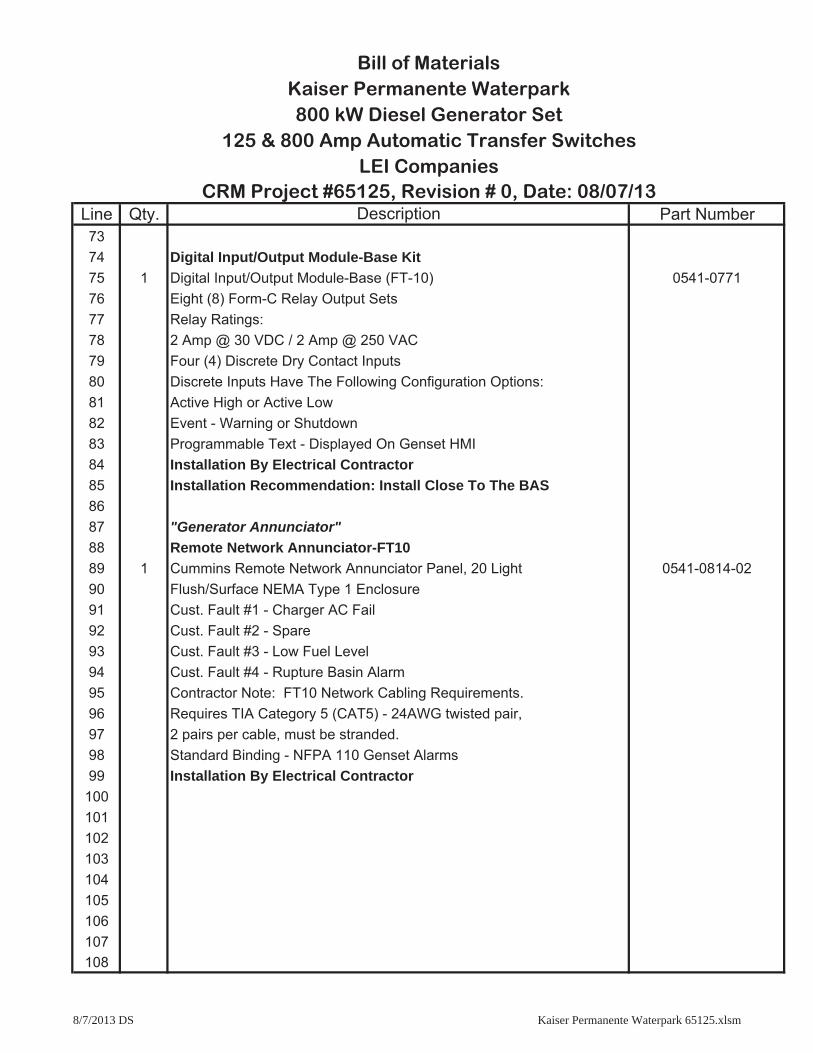
Line Qty. Part Number7374 Digital Input/Output Module-Base Kit75 1 Digital Input/Output Module-Base (FT-10) 0541-077176 Eight (8) Form-C Relay Output Sets77 Relay Ratings:78 2 Amp @ 30 VDC / 2 Amp @ 250 VAC79 Four (4) Discrete Dry Contact Inputs80 Discrete Inputs Have The Following Configuration Options:81 Active High or Active Low82 Event - Warning or Shutdown83 Programmable Text - Displayed On Genset HMI84 Installation By Electrical Contractor85 Installation Recommendation: Install Close To The BAS8687 "Generator Annunciator"88 Remote Network Annunciator-FT1089 1 Cummins Remote Network Annunciator Panel, 20 Light 0541-0814-0290 Flush/Surface NEMA Type 1 Enclosure91 Cust. Fault #1 - Charger AC Fail92 Cust. Fault #2 - Spare93 Cust. Fault #3 - Low Fuel Level94 Cust. Fault #4 - Rupture Basin Alarm95 Contractor Note: FT10 Network Cabling Requirements.96 Requires TIA Category 5 (CAT5) - 24AWG twisted pair,97 2 pairs per cable, must be stranded.98 Standard Binding - NFPA 110 Genset Alarms99 Installation By Electrical Contractor100101102103104105106107108
800 kW Diesel Generator Set125 & 800 Amp Automatic Transfer Switches
Kaiser Permanente Waterpark
Description
LEI CompaniesCRM Project #65125, Revision # 0, Date: 08/07/13
Bill of Materials
8/7/2013 DS Kaiser Permanente Waterpark 65125.xlsm

Line Qty. Part Number109110 "ATS Annunciator"111 Remote Network Annunciator-FT10112 1 Cummins Remote Network Annunciator Panel, 20 Light 0541-0814-02113 Flush/Surface NEMA Type 1 Enclosure114 Cust. Fault #1 - Spare115 Cust. Fault #2 - Spare116 Cust. Fault #3 - Spare117 Cust. Fault #4 - Spare118 Contractor Note: FT10 Network Cabling Requirements.119 Requires TIA Category 5 (CAT5) - 24AWG twisted pair,120 2 pairs per cable, must be stranded.121 Binding - ATS 8 Point122 ATS 1 "Source 1 Available"123 ATS 1 "Source 2 Available"124 ATS 1 "Source 1 Connected"125 ATS 1 "Source 2 Connected"126 ATS 2 "Source 1 Available"127 ATS 2 "Source 2 Available"128 ATS 2 "Source 1 Connected"129 ATS 2 "Source 2 Connected"130 Installation By Electrical Contractor131132133134135136137138139140141142143144
Description
LEI CompaniesCRM Project #65125, Revision # 0, Date: 08/07/13
Bill of MaterialsKaiser Permanente Waterpark800 kW Diesel Generator Set
125 & 800 Amp Automatic Transfer Switches
8/7/2013 DS Kaiser Permanente Waterpark 65125.xlsm

Line Qty. Part Number145146 KP91 - PJ 800 Amp (Main Line Circuit Breaker)147 1 Cummins/Square D Local Main Line Circuit Breaker KP91148 Ref. Square D Catalog #0612CT010R01/06149 Square D/PJ Circuit Breaker - 800 Amp150 PJ-800 Amp Current Sensor Set @ 800 Amp Trip151 UL/IEC Listed, Service Entrance, 100% Rated, 3-Pole152 Interrupting Rating 100 kA @ 240 VAC153 Interrupting Rating 65 kA @ 480 VAC154 MICROLOGIC 3.0 Trip Unit, Type F-Rating Plug155 Adjustable Solid State Trip Unit-672 to 800 Amp156 Auxiliary & Trip Contacts, Left Side157 NEMA Type 1 Enclosure158 Full Neutral Bus & Ground Bond159 Mechanical Lugs: (3) 3/0 AWG-500 KCMIL CU Per Phase160 (Mounted Left Side Of The Control Panel)161162 1 Cummins/Square D Local Main Line Circuit Breaker 0320-2346-06163 Ref. Square D Catalog #0611CT0401R7/05164 Square D/PowerPact 150 Amp HG-Frame/125 Amp Trip165 UL Listed, 3-Pole, 80% Rated166 Interrupting Rating 65 kA @ 240 VAC167 Interrupting Rating 35 kA @ 480 VAC168 Molded Case, Thermo-Magnetic Trip Unit169 1 1 SPDT Switch- Aux. Contact or Trip Alarm (KM69) 0320-1981-01170 Full Neutral Bus & Ground Bond171 Mechanical Lugs: (1) #14 AWG-3/0 AWG AL or CU Per Phase172 (Mounted Right Side Of The Control Panel)173174175176177178179180
800 kW Diesel Generator Set125 & 800 Amp Automatic Transfer Switches
Bill of MaterialsKaiser Permanente Waterpark
LEI CompaniesCRM Project #65125, Revision # 0, Date: 08/07/13
Description
8/7/2013 DS Kaiser Permanente Waterpark 65125.xlsm

Line Qty. Part Number181182 1 Cummins/Square D Local Main Line Circuit Breaker 0320-2347-02183 Ref. Square D Catalog #0611CT0401R7/05184 Square D/PowerPact 250 Amp JG-Frame/225 Amp Trip185 UL Listed, 3-Pole, 80% Rated186 Interrupting Rating 65 kA @ 240 VAC187 Interrupting Rating 35 kA @ 480 VAC188 Molded Case, Thermo-Magnetic Trip Unit189 1 1 SPDT Switch- Aux. Contact or Trip Alarm (KM69) 0320-1981-01190 Full Neutral Bus & Ground Bond191 Mechanical Lugs: (1) 3/0 AWG-350 KCMIL AL or CU Per Phase192 (Mounted Right Side Of The Control Panel)193194 Cummins Engine Coolant & Lube Oil195 1-Lot Initial Fill of Engine Coolant, Ethylene Glycol 50/50196197 1-Lot Initial Fill of Lube Oil, Cummins Blue 15W/40198199 Cummins Factory Testing200 1 Cummins Typical Generator Set Production Test CPG TGSPT201202 Cummins Generator Set Warranty203 1 Warranty: 2-Year Base Warranty - Emergency Standby Power L028204 From Initial Date Of Start-Up205206 Engine Starting Batteries207 2 Diesel Engine Starting Batteries, 8D Lead/Acid Type 908D208209 Engine Starting Batteries Warming Pads210 2 Kim Battery Warming Pads, 120 VAC, 75 Watt Each KB7515211 1 Thermostat, On at 40°F, Off at 60°F DIT46212213214215216
800 kW Diesel Generator Set125 & 800 Amp Automatic Transfer Switches
LEI Companies
Bill of MaterialsKaiser Permanente Waterpark
CRM Project #65125, Revision # 0, Date: 08/07/13Description
8/7/2013 DS Kaiser Permanente Waterpark 65125.xlsm

Line Qty. Part Number217218 SENS 10 Amp Battery Charging System219 1 SENS EnerGenius Battery Charger, NFPA-110 Alarms NRG22-10-RC220 10 Amp @ 12/24 VDC Output, 60HZ-120/208-240 VAC Input221222 822H / ACE Vibration Isolators223 8 ACE Seismic Control Spring Isolators, Zone 2 822H224 3600 Lb. Each, 1" Deflection225226 Crankcase Ventilation System Fittings & Hose Kit (40 CFM)227 1 Racor Crankcase Ventilation Filter System (40-CFM) CCV8000-08R228 1 Racor CCV8000 Fitting / Hose Kit (1-1/2") CCV55067229 1 Racor CCV8000 Replacement Element CCV55222-08230231 Weather Protective Enclosure, UL2200 Listed232 1 Sound Attenuated Genset Enclosure - Level III, 75dBA at 23ft 4072011-L3233 (When Tested In A Free Field Environment)234 UL2200 Listed & Labeled235 14 Gauge Steel Construction236 Four Point Lifting System For Enclosure Only237 Two Sets of Double 72" Doors Per Side238 One Single 36" Door Per Side239 Stainless Steel Refrigerator Handles and Hinges240 Fixed Inlet Louvers Accupax241 Gravity Radiator Discharge Louver With Screen242 Vertical Air Discharge Duct With Screen (Radiator)243 Interior Mounted Exhaust Silencer244 Paint Color: Cummins Beige245246247248249250251252
Bill of MaterialsKaiser Permanente Waterpark800 kW Diesel Generator Set
125 & 800 Amp Automatic Transfer SwitchesLEI Companies
CRM Project #65125, Revision # 0, Date: 08/07/13Description
8/7/2013 DS Kaiser Permanente Waterpark 65125.xlsm

Line Qty. Part Number253254 Exhaust System255 1 Harmony Series Super Critical Grade Cool Series - Silencer K-H1-6-4072001256 Compressed Thermal/Acoustical Fiberglass Packed-257 Shell With 2" Compressed Internal Packing258 Stainless Steel Corrugated Flex Connectors and Rain Cap259 Nut, Bolt and Gasket Hardware260261 Genset Sub-Base Fuel Tank262 1 UL142, Double Wall Sub-Base Fuel Tank 2072010263 UL-142 Listed & Labeled264 Fuel Cell Capacity 450 Gal Useable, 56.1GPH265 Engine Supply & Return Connections266 Integral Welded Fuel Fill Spill Containment267 Stub-Up Zone268 Pads for ACE Mountings Vibration Isolators269 Mechanical Fuel Level Gauge - Krueger KRG270 Low Level Float Switch - 50% Fuel Level - Madison M4500-01BK70271 High Level Float Switch - 90% Fuel Level - Madison M4500-01BK70272 High Level Float Switch - 95% Fuel Level - Madison M4500-01BK70273 Basin Leak Detection Float Switch - Madison M4500-01BK70274 2" Normal Vent-Fuel Cell - C&B 401-01-2000275 2" Normal Vent-Containment Basin - C&B 401-01-2000276 6" Emergency Vent-Fuel Cell - OPW 201M-8081277 6" Emergency Vent-Containment Basin - OPW 201M-8081278 *Extend Normal Vent279 2" Solenoid Valve, 24VDC - Fuel Shut Off S271AF16V5JJ2280 Solenoid Control/ High Level Alarm Box HLA-2281 2" Camlock Locking Cap - OPW 634B-1050282 2" Inlet Spout 6334B-0150283 Exterior Color - Black Paint Paint284285286287288
800 kW Diesel Generator Set125 & 800 Amp Automatic Transfer Switches
LEI CompaniesCRM Project #65125, Revision # 0, Date: 08/07/13
Description
Bill of MaterialsKaiser Permanente Waterpark
8/7/2013 DS Kaiser Permanente Waterpark 65125.xlsm
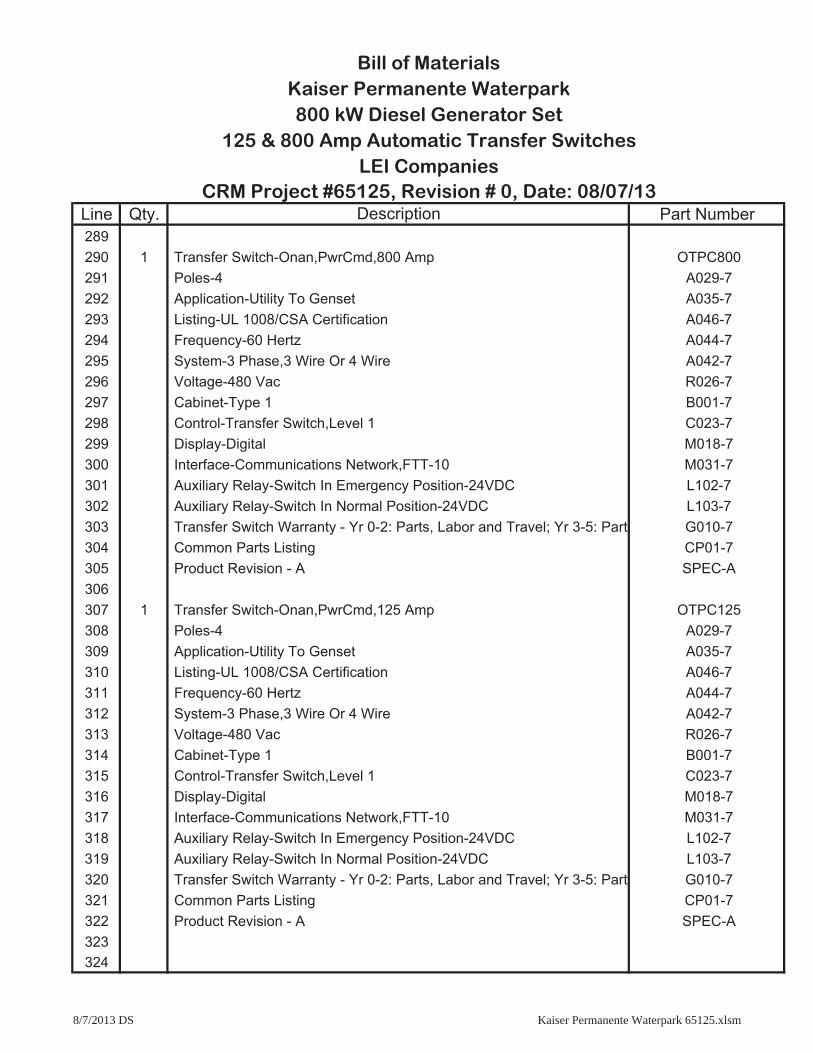
Line Qty. Part Number289290 1 Transfer Switch-Onan,PwrCmd,800 Amp OTPC800291 Poles-4 A029-7292 Application-Utility To Genset A035-7293 Listing-UL 1008/CSA Certification A046-7294 Frequency-60 Hertz A044-7295 System-3 Phase,3 Wire Or 4 Wire A042-7296 Voltage-480 Vac R026-7297 Cabinet-Type 1 B001-7298 Control-Transfer Switch,Level 1 C023-7299 Display-Digital M018-7300 Interface-Communications Network,FTT-10 M031-7301 Auxiliary Relay-Switch In Emergency Position-24VDC L102-7302 Auxiliary Relay-Switch In Normal Position-24VDC L103-7303 Transfer Switch Warranty - Yr 0-2: Parts, Labor and Travel; Yr 3-5: Parts G010-7304 Common Parts Listing CP01-7305 Product Revision - A SPEC-A306307 1 Transfer Switch-Onan,PwrCmd,125 Amp OTPC125308 Poles-4 A029-7309 Application-Utility To Genset A035-7310 Listing-UL 1008/CSA Certification A046-7311 Frequency-60 Hertz A044-7312 System-3 Phase,3 Wire Or 4 Wire A042-7313 Voltage-480 Vac R026-7314 Cabinet-Type 1 B001-7315 Control-Transfer Switch,Level 1 C023-7316 Display-Digital M018-7317 Interface-Communications Network,FTT-10 M031-7318 Auxiliary Relay-Switch In Emergency Position-24VDC L102-7319 Auxiliary Relay-Switch In Normal Position-24VDC L103-7320 Transfer Switch Warranty - Yr 0-2: Parts, Labor and Travel; Yr 3-5: Parts G010-7321 Common Parts Listing CP01-7322 Product Revision - A SPEC-A323324
Bill of MaterialsKaiser Permanente Waterpark800 kW Diesel Generator Set
Description
125 & 800 Amp Automatic Transfer SwitchesLEI Companies
CRM Project #65125, Revision # 0, Date: 08/07/13
8/7/2013 DS Kaiser Permanente Waterpark 65125.xlsm

Line Qty. Part Number325326 1 #2 Diesel Fuel - Initial Fill - 475 Gallons #2 Diesel Fuel327328 CRM On-Site Testing329 1 CRM Site Tests: 4-Hour Load Test330 4-Hour Load Test With CRM Resistive/Reactive Load Bank331332 DQCC O&M Manual333 4 Operator's & Maintenance Manuals - DQCC 0998-0058-02334 Note: 1-Set Shipped with Each Generator Set335336 OTPC O&M Manual337 4 Operator's & Maintenance Manuals-OTPC 0999-0024338 Note: 1-Set Shipped with Each Transfer Switch339340 Spare Parts341 4 Engine Oil Filters (Fleetguard) LF670342 2 Engine Air Filter (Fleetguard) AF25593343 4 Engine Fuel Filters (Fleetguard) FS1006344 2 Engine Coolant Filter (Fleetguard) WF2076345 6 Control Panel Indicator Lamps (LED) 322-0491346 4 ATM Mini 2-Amp Fuse-Gray ATM-2347 4 ATM Mini 5-Amp Fuse-Tan ATM-5348 4 ATM Mini 10-Amp Fuse-Red ATM-10349350351352353354355356357358359360
Bill of MaterialsKaiser Permanente Waterpark800 kW Diesel Generator Set
125 & 800 Amp Automatic Transfer SwitchesLEI Companies
CRM Project #65125, Revision # 0, Date: 08/07/13Description
8/7/2013 DS Kaiser Permanente Waterpark 65125.xlsm
cumminspower.com©2013 Cummins Power Generation Inc. | S-1551h (3/13)
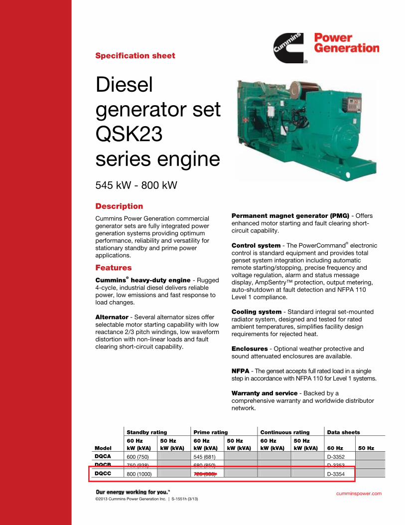
Specification sheet
Diesel generator set QSK23 series engine 545 kW - 800 kW
DescriptionCummins Power Generation commercial generator sets are fully integrated power generation systems providing optimum performance, reliability and versatility for stationary standby and prime power applications.
Features
Cummins® heavy-duty engine - Rugged 4-cycle, industrial diesel delivers reliable power, low emissions and fast response to load changes. Alternator - Several alternator sizes offer selectable motor starting capability with low reactance 2/3 pitch windings, low waveform distortion with non-linear loads and fault clearing short-circuit capability.
Permanent magnet generator (PMG) - Offers enhanced motor starting and fault clearing short-circuit capability. Control system - The PowerCommand® electronic control is standard equipment and provides total genset system integration including automatic remote starting/stopping, precise frequency and voltage regulation, alarm and status message display, AmpSentry™ protection, output metering, auto-shutdown at fault detection and NFPA 110 Level 1 compliance. Cooling system - Standard integral set-mounted radiator system, designed and tested for rated ambient temperatures, simplifies facility design requirements for rejected heat. Enclosures - Optional weather protective and sound attenuated enclosures are available. NFPA - The genset accepts full rated load in a single step in accordance with NFPA 110 for Level 1 systems. Warranty and service - Backed by a comprehensive warranty and worldwide distributor network.
Standby rating Prime rating Continuous rating Data sheets
Model 60 Hz kW (kVA)
50 Hz kW (kVA)
60 Hz kW (kVA)
50 Hz kW (kVA)
60 Hz kW (kVA)
50 Hz kW (kVA) 60 Hz 50 Hz
DQCA 600 (750) 545 (681) D-3352
DQCB 750 (938) 680 (850) D-3353
DQCC 800 (1000) 725 (906) D-3354

cumminspower.com©2013 Cummins Power Generation Inc. | S-1551h (3/13)
Generator set specifications Governor regulation class ISO 8528 Part 1 Class G3 Voltage regulation, no load to full load ± 0.5% Random voltage variation ± 0.5% Frequency regulation Isochronous Random frequency variation ± 0.25% Radio frequency emissions compliance IEC 801.2 through IEC 801.5; MIL STD 461C, Part 9
Engine specifications Bore 169.9 mm (6.69 in)
Stroke 169.9 mm (6.69 in)
Displacement 23.15 litres (1413 in3)
Configuration Cast iron, in line 6 cylinder
Battery capacity 1400 amps minimum at ambient temperature of 0 °C to 10 °C (32 °F to 50 °F)
Battery charging alternator 35 amps
Starting voltage 24 volt, negative ground
Fuel system Direct injection: number 2 diesel fuel, fuel filter, automatic electric fuel shutoff
Fuel filter Spin-on fuel filters with water separator
Air cleaner type Dry replaceable element with restriction indicator
Lube oil filter type(s) Fleetguard dual venturi spin-on, combination full flow and bypass filters
Standard cooling system High ambient radiator
Alternator specifications Design Brushless, 4 pole, drip proof, revolving field Stator 2/3 pitch Rotor Single bearing flexible discs Insulation system Class H Standard temperature rise 125 ºC standby at 40 °C ambient Exciter type PMG (permanent magnet generator) Phase rotation A (U), B (V), C (W) Alternator cooling Direct drive centrifugal blower fan AC waveform total harmonic distortion < 5% no load to full linear load, < 3% for any single harmonic Telephone influence factor (TIF) < 50 per NEMA MG1-22.43 Telephone harmonic factor (THF) < 3
Available voltages
60 Hz line-neutral/line-line 50 Hz line-neutral/line-line 110/190
115/200 120/208
127/220 139/240 220/380
230/380 240/416 255/440
277/480 347/600
Note: Consult factory for other voltages.
Generator set options and accessories
Engine 208/240/480 V coolant heater for ambient above 4.5 ºC (40 ºF)
Fuel/water separator Heavy duty air cleaner
Control Panel 120/240 V 100 W control anti-condensation heater
Paralleling configuration Remote fault signal package
Run relay package
Alternator 80 C rise 105 C rise 125 C rise 120/240 V anti-condensation heater
Temperature sensor - alternator bearing RTD
Cooling system 50 C ambient
Exhaust System Industrial grade exhaust silencer
Residential grade exhaust silencer
Critical grade exhaust silencer
Generator set AC entrance box Battery Battery rack with hold-down - floor standing
Circuit breaker - set mounted Disconnect switch - set mounted
PowerCommand Network Remote annunciator panel Spring isolators 2 year warranty 5 year warranty 10 year major components warranty
Note: Some options may not be available on all models - consult factory for availability.

cumminspower.com©2013 Cummins Power Generation Inc. | S-1551h (3/13)
Control system PCC3201
PowerCommand control is an integrated generator set control system providing governing, voltage regulation, engine protection and operator interface functions. Major features include: Integral AmpSentry™ Protective Relay providing a full range of alternator protection functions that are matched to the alternator provided.
Battery monitoring and testing features and smart starting control system.
Three phase sensing, full wave rectified voltage regulation system, with a PWM output for stable operation with all load types.
Control suitable for operation in ambient temperatures from -40 °C to +70 °C (-40 °F to +158 °F) and altitudes to 5000 meters (13,000 feet).
Prototype tested; UL, CSA, and CE compliant. InPower™ PC-based service tool available for detailed diagnostics.
Optional Echelon® LONWORKS® network interface.
Operator/display panel Off/manual/auto mode switch Manual run/stop switch Panel lamp test switch Emergency stop switch Exercise switch Alpha-numeric display with pushbutton access for viewing engine and alternator data and providing setup, controls and adjustments
LED lamps indicating not in auto, common warning, common shutdown, remote start
Configurable for local language
Engine protection Overspeed shut down Low oil pressure warning and shut down High coolant temperature warning and shut down High oil temperature warning Low coolant level warning or shut down Low coolant temperature warning High and low battery voltage warning Weak battery warning Dead battery shut down Fail to start (overcrank) shut down Fail to crank shut down Redundant start disconnect Cranking lockout Sensor failure indication
Engine data DC voltage Lube oil pressure Coolant temperature Lube oil temperature Engine speed Engine ECM data
AmpSentry AC protection Over current and short-circuit shut down Over current warning Single and three phase fault regulation Over and under voltage shut down Over and under frequency shut down Overload warning with alarm contact Reverse power and reverse Var shut down
Alternator data Line-to-line and line-to-neutral AC volts Three phase AC current Frequency Total and individual phase power factor, kW and kVA Bus voltage and frequency (with paralleling options)
Other data Genset model data Start attempts, starts, running hours kW hours (total and since reset) Fault history Load profile (accessible with InPower)
Governing Digital electronic isochronous governor Temperature dynamic governing Smart idle speed mode
Voltage regulation Digital PWM electronic voltage regulation Three phase line-to-neutral sensing Single and three phase fault regulation Configurable torque matching
Control functions Data logging on faults Fault simulation (requires InPower) Time delay start and cooldown Cycle cranking Configurable customer outputs (4) Configurable network inputs (8) and outputs (16) (with optional network)
Remote emergency stop
Paralleling (Option) Active digital phase lock loop synchronizer Isochronous kW and kVar load sharing controls kW import/export and kVar/PF control for utility (mains) paralleling
Options Thermostatically controlled space heater Key-type mode switch Ground fault module Auxiliary relays (3) Echelon LONWORKS interface Modion Gateway to convert to Modbus (loose) PowerCommand iWatch web server for remote monitoring and alarm notification (loose)
Digital input and output module(s) (loose) Remote annunciator (loose) Paralleling Power transfer control
For further detail see document S-1444.

North America1400 73rd Avenue N.E. Minneapolis, MN 55432 USA Phone 763 574 5000 Fax 763 574 5298
©2013 Cummins Power Generation Inc. All rights reserved. Cummins Power Generation and Cummins are registered trademarks of Cummins Inc. PowerCommand, AmpSentry, InPower and “Our energy working for you.” are trademarks of Cummins Power Generation. Other company, product, or service names may be trademarks or service marks of others. Specifications are subject to change without notice.
S-1551h (3/13)
cumminspower.com
Emergency standby power (ESP): Applicable for supplying power to varying electrical load for the duration of power interruption of a reliable utility source. Emergency Standby Power (ESP) is in accordance with ISO 8528. Fuel Stop power in accordance with ISO 3046, AS 2789, DIN 6271 and BS 5514.
Limited-time running power (LTP): Applicable for supplying power to a constant electrical load for limited hours. Limited Time Running Power (LTP) is in accordance with ISO 8528.
Prime power (PRP): Applicable for supplying power to varying electrical load for unlimited hours. Prime Power (PRP) is in accordance with ISO 8528. Ten percent overload capability is available in accordance with ISO 3046, AS 2789, DIN 6271 and BS 5514.
Base load (continuous) power (COP): Applicable for supplying power continuously to a constant electrical load for unlimited hours. Continuous Power (COP) in accordance with ISO 8528, ISO 3046, AS 2789, DIN 6271 and BS 5514.
This outline drawing is for reference only. See respective model data sheet for specific model outline drawing number. Do not use for installation design
Model Dim “A” mm (in.)
Dim “B” mm (in.)
Dim “C” mm (in.)
Set Weight* dry kg (lbs)
Set Weight* wet kg (lbs)
DQCA 4394.5 (173) 1715 (68) 2060.1 (81.1) 6377 (14061) 6518 (14372) DQCB 4394.5 (173) 1715 (68) 2060.1 (81.1) 6377 (14061) 6518 (14372) DQCC 4394.5 (173) 1715 (68) 2060.1 (81.1) 6377 (14061) 6518 (14372)
* Weights represent a set with standard features. See outline drawings for weights of other configurations.
Codes and standards Codes or standards compliance may not be available with all model configurations – consult factory for availability.
This generator set is designed in facilities certified to ISO 9001 and manufactured in facilities certified to ISO 9001 or ISO 9002.
The generator set is available listed to UL 2200, Stationary Engine Generator Assemblies for all 60 Hz low voltage models. The PowerCommand control is Listed to UL 508 - Category NITW7 for U.S. and Canadian usage. Circuit breaker assemblies are UL 489 Listed for 100% continuous operation and also UL 869A Listed Service Equipment.
The Prototype Test Support (PTS) program verifies the performance integrity of the generator set design. Cummins Power Generation products bearing the PTS symbol meet the prototype test requirements of NFPA 110 for Level 1 systems.
U.S. EPA
Engine certified to Stationary Emergency U.S. EPA New Source Performance Standards, 40 CFR 60 subpart IIII Tier 2 exhaust emission levels. U.S. applications must be applied per this EPA regulation.
All low voltage models are CSA certified to product class 4215-01.
International Building Code
The generator set package is available certified for seismic application in accordance with the following International Building Code: IBC2000, IBC2003, IBC2006, IBC2009 and IBC2012.
Warning: Back feed to a utility system can cause electrocution and/or property damage. Do not connect to any building’s electrical system except through an approved device or after building main switch is open.

2010 Cummins Power Generation Inc. All rights reserved. Cummins Power Generation and Cummins are registered trademarks of Cummins Inc. “Our energy working for you.” is a trademark of Cummins Power Generation. Specifications are subject to change without notice. D-3354f (7/10)
Model: DQCC Frequency: 60 Fuel type: Diesel KW rating: 800 standby 725 prime Emissions level: EPA NSPS Stationary Emergency Tier 2
Exhaust emission data sheet: EDS-1088 Exhaust emission compliance sheet: EPA-1122 Sound performance data sheet: MSP-1066 Cooling performance data sheet: MCP-175 Prototype test summary data sheet: PTS-160 Standard set-mounted radiator cooling outline: Optional set-mounted radiator cooling outline: Optional heat exchanger cooling outline: Optional remote radiator cooling outline:
Standby Prime Continuous Fuel consumption kW (kVA) kW (kVA) kW (kVA) Ratings 800 (1000) 725 (906) Load 1/4 1/2 3/4 Full 1/4 1/2 3/4 Full Full US gph 17.0 29.0 41.0 53.0 15.5 27.5 38.0 48.0 L/hr 64.4 109.8 155.2 200.6 58.7 104.1 143.8 181.7
Engine Standby rating
Prime rating
Continuous rating
Engine manufacturer Cummins Inc.
Engine model QSK23-G7 NR2
Configuration Cast Iron, in line 6 cylinder
Aspiration Turbocharged and air-to-air aftercooled
Gross engine power output, kWm (bhp) 910 (1220) 809 (1085)
BMEP at set rated load, kPa (psi) 2510 (364) 2282 (331)
Bore, mm (in) 170 (6.69)
Stroke, mm (in) 170 (6.69)
Rated speed, rpm 1800
Piston speed, m/s (ft/min) 10.21 (2010)
Compression ratio 16:1
Lube oil capacity, L (qt) 102 (108)
Overspeed limit, rpm 2100
Regenerative power, kW 93
Fuel flow Maximum fuel flow, L/hr (US gph) 685 (181)
Maximum fuel inlet restriction, kPa (in Hg) 13.44 (4)
Maximum fuel inlet temperature, °C (°F) 71 (160)
Generator set data sheet

Our energy working for you.™
www.cumminspower.com
2010 Cummins Power Generation Inc. All rights reserved. Cummins Power Generation and Cummins are registered trademarks of Cummins Inc. “Our energy working for you.” is a trademark of Cummins Power Generation. Specifications are subject to change without notice. D-3354f (7/10)
Air Standby Rating
Prime rating
Continuous rating
Combustion air, m3/min (scfm) 64 (2265) 62 (2201)
Maximum air cleaner restriction, kPa (in H2O) 6.2 (25)
Alternator cooling air, m3/min (cfm) 117 (4156)
Exhaust Exhaust flow at set rated load, m3/min (cfm) 155 (5455) 147 (5191)
Exhaust temperature, °C (°F) 483 (902) 461 (862)
Maximum back pressure, kPa (in H2O) 10.1 (40.8)
Standard set-mounted radiator cooling Ambient design, °C ( °F) 45 (113)
Fan load, kWm (HP) 27 (36)
Coolant capacity (with radiator), L (US gal) 89 (23.5)
Cooling system air flow, m3/min (scfm) 1252 (44183)
Total heat rejection, MJ/min (Btu/min) 33.52 (31793) 30.22 (28672)
Maximum cooling air flow static restriction, kPa (in H2O) 0.12 (0.5)
Maximum fuel return line restriction kPa (in Hg) 30.47 (9)
Optional set-mounted radiator cooling
Ambient design, °C (°F)
Fan load, kWm (HP)
Coolant capacity (with radiator), L (US gal)
Cooling system air flow, m3/min (scfm)
Total heat rejection, MJ/min (Btu/min)
Maximum cooling air flow static restriction, kPa (in H2O)
Maximum fuel return line restriction, kPa (in Hg)
Optional heat exchanger cooling
Set coolant capacity, L (US gal) Heat rejected, jacket water circuit, MJ/min (Btu/min) Heat rejected, aftercooler circuit, MJ/min (Btu/min) Heat rejected, fuel circuit, MJ/min (Btu/min) Total heat radiated to room, MJ/min (Btu/min) Maximum raw water pressure, jacket water circuit, kPa (psi) Maximum raw water pressure, aftercooler circuit, kPa (psi) Maximum raw water pressure, fuel circuit, kPa (psi) Maximum raw water flow, jacket water circuit, L/min (US gal/min) Maximum raw water flow, aftercooler circuit, L/min (US gal/min) Maximum raw water flow, fuel circuit, L/min (US gal/min) Minimum raw water flow at 27 °C (80 °F) inlet temp, jacket water circuit, L/min (US gal/min)
Minimum raw water flow at 27 °C (80 °F) inlet temp, aftercooler circuit, L/min (US gal/min)
Minimum raw water flow at 27 °C (80 °F) inlet temp, fuel circuit, L/min (US gal/min)
Raw water delta P at min flow, jacket water circuit, kPa (psi) Raw water delta P at min flow, aftercooler circuit, kPa (psi) Raw water delta P at min flow, fuel circuit, kPa (psi) Maximum jacket water outlet temp, °C (°F) Maximum aftercooler inlet temp, °C (°F) Maximum aftercooler inlet temp at 25 °C (77 °F) ambient, °C ( °F) Maximum fuel return line restriction, kPa (in Hg)

Our energy working for you.™
www.cumminspower.com
2010 Cummins Power Generation Inc. All rights reserved. Cummins Power Generation and Cummins are registered trademarks of Cummins Inc. “Our energy working for you.” is a trademark of Cummins Power Generation. Specifications are subject to change without notice. D-3354f (7/10)
Optional remote radiator cooling1 Standby rating
Prime rating
Continuous rating
Set coolant capacity, L (US gal) Max flow rate at max friction head, jacket water circuit, L/min (US gal/min) Max flow rate at max friction head, aftercooler circuit, L/min (US gal/min)
Heat rejected, jacket water circuit, MJ/min (Btu/min) Heat rejected, aftercooler circuit, MJ/min (Btu/min) Heat rejected, fuel circuit, MJ/min (Btu/min) Total heat radiated to room, MJ/min (Btu/min) Maximum friction head, jacket water circuit, kPa (psi) Maximum friction head, aftercooler circuit, kPa (psi) Maximum static head, jacket water circuit, m (ft) Maximum static head, aftercooler circuit, m (ft) Maximum jacket water outlet temp, C ( F) Maximum aftercooler inlet temp at 25 C (77 F) ambient, C ( F) Maximum aftercooler inlet temp, C ( F) Maximum fuel flow, L/hr (US gph) Maximum fuel return line restriction, kPa (in Hg)
Weights2
Unit dry weight kgs (lbs) 6379 (14061)
Unit wet weight kgs (lbs) 6521 (14372)
Notes: 1 For non-standard remote installations contact your local Cummins Power Generation representative. 2 Weights represent a set with standard features. See outline drawing for weights of other configurations.
Derating factors
Standby Engine power available up to 1137 m (3730 ft) at ambient temperatures up to 40 °C (104 °F). Above these elevations, derate at 4.4% per 305 m (1000 ft). Above 40 °C (104 °F) derate 10% per 10 °C (18 °F).
Prime Engine power available up to 754 m (2475 ft) at ambient temperatures up to 40 °C (104 °F). Above these elevations, derate at 4.5% per 305 m (1000 ft). Above 40 °C (104 °F) derate 20.9% per 10 °C (18 °F).
Continuous
Ratings definitions Emergency standby power (ESP):
Limited-time running power (LTP):
Prime power (PRP):
Base load (continuous) power (COP):
Applicable for supplying power to varying electrical load for the duration of power interruption of a reliable utility source. Emergency Standby Power (ESP) is in accordance with ISO 8528. Fuel Stop power in accordance with ISO 3046, AS 2789, DIN 6271 and BS 5514.
Applicable for supplying power to a constant electrical load for limited hours. Limited Time Running Power (LTP) is in accordance with ISO 8528.
Applicable for supplying power to varying electrical load for unlimited hours. Prime Power (PRP) is in accordance with ISO 8528. Ten percent overload capability is available in accordance with ISO 3046, AS 2789, DIN 6271 and BS 5514.
Applicable for supplying power continuously to a constant electrical load for unlimited hours. Continuous Power (COP) is in accordance with ISO 8528, ISO 3046, AS 2789, DIN 6271 and BS 5514.

Our energy working for you.™
www.cumminspower.com
2010 Cummins Power Generation Inc. All rights reserved. Cummins Power Generation and Cummins are registered trademarks of Cummins Inc. “Our energy working for you.” is a trademark of Cummins Power Generation. Specifications are subject to change without notice. D-3354f (7/10)
Alternator data
Voltage Connection1 Temp rise degrees C Duty2
Single phase factor3
Max surge kVA4
Winding No.
Alternator data sheet
Feature Code
277/480 Wye 125/105 S/P 2944 312 ADS-309 B276-2 277/480 Wye 105 S 3313 312 ADS-310 B280-2 347/600 Wye 125/105 S/P 2944 7 ADS-309 B550-2 220/380 Wye 105/80 S/P 4234 312 ADS-312 B599-2 277/480 Wye 80 S 3866 312 ADS-311 B601-2 347/600 Wye 105/80 S/P 3866 7 ADS-311 B603-2 347/600 Wye 80 S 3866 7 ADS-311 B604-2 220/380 Wye 80 P 3866 312 ADS-311 B687-2 277/480 Wye 80 P 3866 312 ADS-311 B694-2 208/416 Wye 125/105 S/P 3313 311 ADS-310 B732-2 208/416 Wye 105/80 S/P 3866 311 ADS-311 B733-2 208/416 Wye 80 S 4234 311 ADS-312 B734-2 220/380 Wye 125 P 3313 312 ADS-310 B736-2 220/380 Wye 125/105 S/P 3866 312 ADS-311 B737-2 255/440 Wye 125/105 S/P 3313 312 ADS-310 B741-2
Notes: 1 Limited single phase capability is available from some three phase rated configurations. To obtain single phase rating, multipy the three phase kW rating by the Single Phase Factor3. All single phase ratings are at unity power factor.
2 Standby (S), Prime (P) and Continuous ratings (C).
3 Factor for the Single Phase Output from Three Phase Alternator formula listed below.
4 Maximum rated starting kVA that results in a minimum of 90% of rated sustained voltage during starting.
Formulas for calculating full load currents: Three phase output Single phase output
Cummins Power Generation 1400 73rd Avenue N.E. Minneapolis, MN 55432 USA Phone: 763 574 5000 Fax: 763 574 5298
Warning: Back feed to a utility system can cause electrocution and/or property damage. Do not connect to any building’s electrical system except through an approved device or after building main switch is open.
Voltage1000 x eFactorSinglePhas x kW
0.8 x 1.73 x Voltage1000 x kW

2008 Cummins Power Generation Inc. All rights reserved Specifications subject to change without notice Cummins Power Generation and Cummins are registered trademarks of Cummins Inc. PowerCommand, InPower, AmpSentry and “Our energy working for you.” are trademarks of Cummins Power Generation. Other company, product, or service names may be trademarks or service marks of others. S-1409g (4/08) Page 1 of 8
PowerCommand® 2100 digital generator set control
Description
The PowerCommand® 2100 Control is a microprocessor-based generator set monitoring, metering and control system. The control provides an operator interface to the genset, digital voltage regulation, digital governing and generator set protective functions. The integration of all the functions into a single control system provides enhanced reliability and performance compared to conventional control systems.
The PowerCommand control is designed for mounting on the generator set and is suitable for use on a wide range of generator sets in non-paralleling applications. The PowerCommand Control will directly read AC voltages up to 600 VAC and can be configured for any frequency, voltage and power connection configuration from 120 to 600 VAC.
The control offers a wide range of standard control and digital display features so custom control configurations are not needed to meet application specifications. System reliability is not compromised by use of untested special components.
Power for PowerCommand Control is usually derived from the generator set starting batteries. It functions without degradation in performance over a voltage range from 8 VDC to 35 VDC.
Features
Digital engine speed governing controls - Provide isochronous frequency regulation (optional on some genset models).
Digital voltage regulation – 3-phase sensing.
AmpSentry™ protective relay – UL Listed, true alternator over current protection.
Analog and digital AC output metering.
Battery monitoring system - Senses and warns against a weak battery condition.
Digital alarm and status message display.
Generator set monitoring - Displays status of all critical engine and alternator functions.
Smart starting control system - Temperature dynamic integrated fuel ramping to limit black smoke and frequency overshoot, in addition to optimized cold weather starting.
PCCNet Interface - A proprietary RS485 network interface to allow easy plug and play interface to remote annunciators, relay modules for extensible I/O and other devices.
Advanced serviceability - Interfaces to InPower™, a PC-based software service tool. A version of InPower is available for customer use.
PowerCommand LonWorks® network (optional) - Provides interfaces to external devices through a twisted pair wire and other media.
Certifications - Suitable for use on generator sets that are designed, manufactured, tested, and certified to relevant UL, NFPA, ISO, IEC, and CSA standards.
Warranty and service - Backed by a comprehensive warranty and worldwide distributor service network.
Our energy working for you.™
www.cumminspower.com
2008 Cummins Power Generation Inc. All rights reserved Specifications subject to change without notice Cummins Power Generation and Cummins are registered trademarks of Cummins Inc. PowerCommand, InPower, AmpSentry and “Our energy working for you.” are trademarks of Cummins Power Generation. Other company, product, or service names may be trademarks or service marks of others. S-1409g (4/08) Page 2 of 8
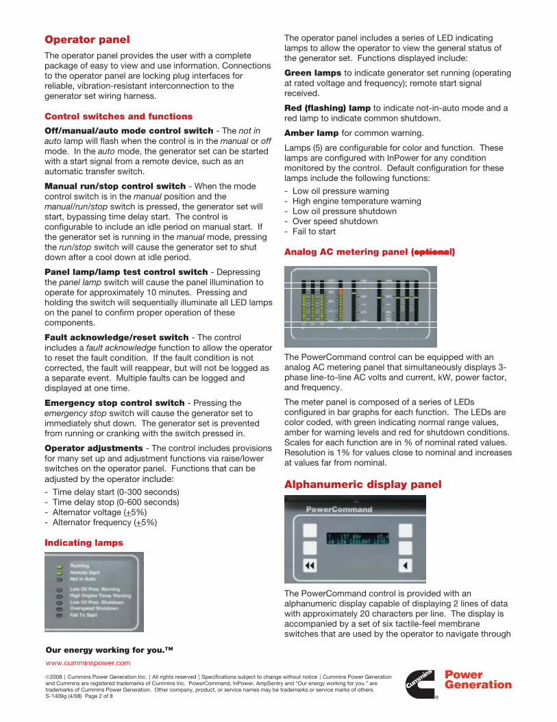
Operator panel The operator panel provides the user with a complete package of easy to view and use information. Connections to the operator panel are locking plug interfaces for reliable, vibration-resistant interconnection to the generator set wiring harness.
Control switches and functions
Off/manual/auto mode control switch - The not in auto lamp will flash when the control is in the manual or off mode. In the auto mode, the generator set can be started with a start signal from a remote device, such as an automatic transfer switch.
Manual run/stop control switch - When the mode control switch is in the manual position and the manual/run/stop switch is pressed, the generator set will start, bypassing time delay start. The control is configurable to include an idle period on manual start. If the generator set is running in the manual mode, pressing the run/stop switch will cause the generator set to shut down after a cool down at idle period.
Panel lamp/lamp test control switch - Depressing the panel lamp switch will cause the panel illumination to operate for approximately 10 minutes. Pressing and holding the switch will sequentially illuminate all LED lamps on the panel to confirm proper operation of these components.
Fault acknowledge/reset switch - The control includes a fault acknowledge function to allow the operator to reset the fault condition. If the fault condition is not corrected, the fault will reappear, but will not be logged as a separate event. Multiple faults can be logged and displayed at one time.
Emergency stop control switch - Pressing the emergency stop switch will cause the generator set to immediately shut down. The generator set is prevented from running or cranking with the switch pressed in.
Operator adjustments - The control includes provisions for many set up and adjustment functions via raise/lower switches on the operator panel. Functions that can be adjusted by the operator include: - Time delay start (0-300 seconds) - Time delay stop (0-600 seconds) - Alternator voltage (+5%) - Alternator frequency (+5%)
Indicating lamps
The operator panel includes a series of LED indicating lamps to allow the operator to view the general status of the generator set. Functions displayed include:
Green lamps to indicate generator set running (operating at rated voltage and frequency); remote start signal received. Red (flashing) lamp to indicate not-in-auto mode and a red lamp to indicate common shutdown.
Amber lamp for common warning.
Lamps (5) are configurable for color and function. These lamps are configured with InPower for any condition monitored by the control. Default configuration for these lamps include the following functions:
- Low oil pressure warning - High engine temperature warning - Low oil pressure shutdown - Over speed shutdown - Fail to start
Analog AC metering panel (optional)
The PowerCommand control can be equipped with an analog AC metering panel that simultaneously displays 3-phase line-to-line AC volts and current, kW, power factor, and frequency.
The meter panel is composed of a series of LEDs configured in bar graphs for each function. The LEDs are color coded, with green indicating normal range values, amber for warning levels and red for shutdown conditions. Scales for each function are in % of nominal rated values. Resolution is 1% for values close to nominal and increases at values far from nominal.
Alphanumeric display panel
The PowerCommand control is provided with an alphanumeric display capable of displaying 2 lines of data with approximately 20 characters per line. The display is accompanied by a set of six tactile-feel membrane switches that are used by the operator to navigate through

Our energy working for you.™
www.cumminspower.com
2008 Cummins Power Generation Inc. All rights reserved Specifications subject to change without notice Cummins Power Generation and Cummins are registered trademarks of Cummins Inc. PowerCommand, InPower, AmpSentry and “Our energy working for you.” are trademarks of Cummins Power Generation. Other company, product, or service names may be trademarks or service marks of others. S-1409g (4/08) Page 3 of 8
control menus and to make control adjustments. (There are no rotary potentiometers in the control. All adjustments are made via the display panel or InPower). Display is configurable for multiple languages. It is configurable for units of measurement.
All data on the control can be viewed by scrolling through screens with the navigation keys.
The control displays all active fault conditions with the latest displayed first. Active and inactive faults are displayed.
The display panel includes a screen-saver timer that will turn off the display after 30 minutes of inactivity. Touching any key will turn the screen back on.
Generator set hardware data - Generator set rating in kVA, complete generator set model number and provisions for generator set serial number, engine model and serial number, and alternator model and serial number. The control stores the part number of the control and the software version present in the control. This information is read using InPower.
Data logs - Number of start attempts and number of start attempts since reset. Number of times generator set has run and duration of generator set running time. Generator set kWh produced. The control also stores number of start attempts, operating hours and kW hours since each has been reset. This data is read with InPower.
Adjustment history - Provides a record of adjustment and setting changes made on the control and identifies whether adjustment was made via the operator panel or with a service tool. If a service tool is used, the control provides a record of the serial number of the tool used. This information is read with InPower.
Fault history - Provides a record of the most recent fault conditions with time stamp, along with the number of times each fault has occurred. Up to 20 events are stored in the control non-volatile memory.
Load profile data - Control logs data indicating the operating hours at percent of rated kW load in 10% increments. The data is presented on the operator panel based on total operating hours on the generator set based on number of hours under 30% load and number of hours at more than 90% of rated. InPower can be used to read data in detail (10% increments).
Generator set output voltage - All phases, line-to-line and line-to-neutral, accuracy 1%. Data for all phases is displayed simultaneously to allow viewing of voltage balance.
Generator set output current - All phases, accuracy 1%. Data for all phases is displayed simultaneously to allow viewing of load balance.
Generator set output frequency.
Generator set power output - PowerCommand displays generator set kW and kVA output (average and individual phase and direction of flow), and power factor with leading/lagging indication. Accuracy 5%.
Generator set kWh power output - Displays total kilowatt-hours produced by the generator set and total produced since last reset, with time stamp of time of last reset.
Generator set control temperature.
Engine starting battery voltage.
Engine lube oil pressure.
Engine coolant temperature.
Engine lube oil temperature (option on some genset models).
System data display - The generator set will exchange data with Cummins Power Generation transfer switches utilizing PowerCommand transfer controls and other generator sets using the PowerCommand 2100 control that are located on the same site and interconnected using a PowerCommand network. Information displayed from each transfer switch in the system includes: transfer switch name (assigned by customer at site), kW load (when fitted with load monitoring equipment), sources available, source connected and if any alarm conditions are present on the switch. Genset data includes genset name, kW load, status and name of any alarm conditions that are present.
Service adjustments - The operator panel includes provisions for adjustment and set up of all control functions in the generator set. The operator panel includes an access code that is used to protect the control from unauthorized service level adjustments.
Internal control functions
Engine control
Remote start mode - PowerCommand accepts a ground signal from remote devices or a network signal to automatically start the generator set and immediately accelerate to rated speed and voltage.
PowerCommand includes a smart starting system that is designed to quickly start the engine, minimize black smoke, minimize voltage and frequency overshoot, and oscillations on starting. The control system does this by careful control of the engine fuel system and alternator excitation system.
The control can incorporate a time delay start and a warm-up period at idle speed. See Engine governing for details.
Sleep mode - PowerCommand can be configured to include a sleep mode. When enabled, and when the mode select switch is in the off position, the control will revert to

Our energy working for you.™
www.cumminspower.com
2008 Cummins Power Generation Inc. All rights reserved Specifications subject to change without notice Cummins Power Generation and Cummins are registered trademarks of Cummins Inc. PowerCommand, InPower, AmpSentry and “Our energy working for you.” are trademarks of Cummins Power Generation. Other company, product, or service names may be trademarks or service marks of others. S-1409g (4/08) Page 4 of 8
a low power consumption mode until a control switch on the operator panel is operated (reset, panel lamp, manual run or emergency stop).
Data logging - The control maintains a record of manual control operations, warning and shutdown conditions, and other events. The control also stores critical engine and alternator data before and after a fault occurs, for use by InPower and the technician in evaluating the root causes for the fault condition.
Fault simulation mode - PowerCommand, in conjunction with InPower software, will accept commands to allow a technician to verify the proper operation of all protective functions of the control by simulating failure modes or by forcing the control to operate outside of its normal operating ranges.
Engine starting - The control system automatically controls the engine starter and provides proper engine fueling and alternator control to provide fast and efficient starting.
Cycle cranking - Configurable for number of starting cycles (1 to 7) and duration of crank and rest periods. Control includes starter protection algorithms to prevent the operator from specifying a starting sequence that might be damaging.
Time delay start and stop (cool down) - Configurable for time delay of 0-300 seconds prior to starting after receiving a remote start signal; and for time delay of 0-600 seconds prior to ramp-to-idle or shutdown after signal to stop in normal operation modes. Default for both time delay periods is 0 seconds.
Engine governing
The PowerCommand control includes integrated digital governing capability to directly drive an engine fuel control valve. Features of the governing system (when enabled) include:
Isochronous governing - Controls engine speed within +0.25% for any steady state load from no load to full load. Frequency drift will not exceed +0.5% for a 33 °C (60 °F) change in ambient temperature over an 8 hour period.
Temperature dynamics - Modifies the engine fuel system (governing) control parameters as a function of engine temperature. Allows engine to be more responsive when warm and more stable when operating at lower temperature levels.
Smart idle mode - Engine governing can be regulated at an idle speed for a programmed period on automatic stop of the engine or in manual mode. In an automatic mode, the control will bypass the idle period if the engine is at a low load level for sufficient duration for cool down. During idle mode engine protective functions are adjusted for the lower engine speed, and alternator function and protections are disabled.
Idle speed can be initiated by the operator when the generator set is running in the manual mode.
Glow plug control (optional) - Modifies the engine start cycle to include a programmed time period for operation of glow plugs. This feature is available on generator sets that require glow plug control only.
Alternator control
PowerCommand includes an integrated 3-phase line-to-neutral sensing voltage regulation system that is compatible with either shunt or PMG type excitation systems (some generator set models are always PMG). The voltage regulation system is full wave rectified and has a PWM output for good motor starting capability and stability when powering non-linear loads. Major system features include:
Digital output voltage regulation - PowerCommand will regulate output voltage to within 0.5% for any loads between no load and full load. Voltage drift will not exceed +0.5% for a 33 °C (60 °F) change in temperature in an 8 hour period. On engine starting, or sudden load acceptance, voltage is controlled to a maximum of 5% overshoot over nominal level.
Torque-matched V/Hz overload control - The voltage roll-off set point and rate of decay (i.e., the slope of the V/Hz curve) is adjustable in the control.
Fault current regulation - PowerCommand will regulate the output current on any phase to a maximum of 3 times rated current under fault conditions for both single phase and three phase faults. The regulation system will drive a permanent magnet generator (PMG) to provide 3 times rated current on all phases for motor starting and short circuit coordination purposes.
Protective functions On a warning condition the control will indicate a fault by lighting the warning LED on the control panel and displaying the fault name and code on the operator display panel. The nature of the fault and time of occurrence are logged in the control. The service manual and InPower service tool provide service keys and procedures based on the service codes provided.
On a shutdown condition, the control will light the shutdown LED on the control panel, display the fault name and code, initiate shutdown and lock out the generator set. The control maintains a data log of all fault conditions as they occur and time stamps them with the controller run time and engine operating hours data. Adjustments to most set points are made using the InPower service tool.
The control system includes a “fault bypass” mode that may be enabled by a service technician. The fault bypass mode forces the system to function regardless of the status of protective functions. (Each function must be individually bypassed.) In this mode the only protective functions that are operational are over speed, loss of speed sensor, moving the control switch to the off position or pressing the emergency stop switch. The control maintains a record of the time that the mode is enabled,

Our energy working for you.™
www.cumminspower.com
2008 Cummins Power Generation Inc. All rights reserved Specifications subject to change without notice Cummins Power Generation and Cummins are registered trademarks of Cummins Inc. PowerCommand, InPower, AmpSentry and “Our energy working for you.” are trademarks of Cummins Power Generation. Other company, product, or service names may be trademarks or service marks of others. S-1409g (4/08) Page 5 of 8
and all warning or shutdown conditions that have occurred while in the “fault bypass” mode.
The control system automatically captures the generator set logged parameters on a fault condition.
Many protective functions within the control system are configurable for warning, shutdown or both (2 levels). Exceptions to this include functions such as over speed conditions and loss of speed sensing. In addition, some functions can incorporate control functions as a consequence of a fault.
System protective functions:
Ground fault warning (optional) - 600 VAC class generator sets with solid ground. Ground fault sensing is adjustable over a range of 100-1200 amps with time delays of 0-1 second. May be configured for shutdown rather than alarm.
Configurable alarm and status inputs - PowerCommand will accept up to four alarm or status inputs (configurable contact closed to ground or open) to indicate customer-specified conditions. The control is programmable for warning, shutdown or status indication, and for labeling the input. Eight additional faults can be input to the control via the network.
Emergency stop - Annunciated whenever the local or remote emergency stop signal is received. Alarm panel distinguishes between local or remote operation.
Engine protection
Over speed shutdown - Default setting is 115% of nominal.
Low lube oil pressure shutdown - Level is preset to match the capabilities of each engine. Control includes time delays to prevent nuisance shutdown signals.
Low lube oil pressure warning - Level is preset to match the capabilities of each engine. Control includes time delays to prevent nuisance shutdown signals.
High coolant temperature shutdown - Level is preset to match the capabilities of each engine. Control includes time delays to prevent nuisance shutdown signals.
High coolant temperature warning - Level is preset to match the capabilities of each engine. Control includes time delays to prevent nuisance shutdown signals.
High oil temperature warning (optional) - Level is preset to match the capabilities of each engine. Control includes time delays to prevent nuisance shutdown signals.
Low coolant level warning/shutdown - Optional on some genset models.
Low coolant temperature warning - Indicates that engine temperature may not be high enough for a 10-second start or proper load pickup.
Low and high battery voltage warning - Indicates battery charging system failure by continuously monitoring battery voltage.
Weak battery warning - The control system will test the battery bank each time the generator set is signaled to start, and indicate a warning if the generator set battery indicates impending failure.
Dead battery shutdown - Indicates that generator set failed to start due to failed starting battery.
Fail to start (overcrank) shutdown.
Fail to crank shutdown - Control has signaled starter to crank engine but engine does not rotate.
Redundant starter disconnect.
Cranking lockout - The control will not allow the starter to attempt to engage or to crank the engine when the engine is rotating.
Sensor failure indication - All analog sensors are provided with sensor failure logic to indicate if the sensor or interconnecting wiring has failed. Separate indication is provided for fail high or low.
AmpSentry protective relay
AmpSentry protective relay is a UL Listed comprehensive monitoring and control system integral to the PowerCommand Control System that guards the electrical integrity of the alternator and power system by providing protection against a wide array of fault conditions in the generator set or in the load. It also provides single and three phase fault current regulation so that downstream protective devices have the maximum current available to quickly clear fault conditions without subjecting the alternator to potentially catastrophic failure conditions. See document R1053 below for a full size time over current curve.
Over current warning - Output current on any phase at more than 110% of rating for more than 60 seconds or more than 400% for more than 1 second.
Over current shutdown (51) - Output current on any phase is more than 110%, less than 175% of rating and approaching thermal damage point of alternator. Control includes algorithms to protect alternator from repeated over current conditions over a short period of time.

Our energy working for you.™
www.cumminspower.com
2008 Cummins Power Generation Inc. All rights reserved Specifications subject to change without notice Cummins Power Generation and Cummins are registered trademarks of Cummins Inc. PowerCommand, InPower, AmpSentry and “Our energy working for you.” are trademarks of Cummins Power Generation. Other company, product, or service names may be trademarks or service marks of others. S-1409g (4/08) Page 6 of 8
Short circuit shutdown - Output current on any phase is more than 110%, more than 175% of rating, and approaching thermal damage point of alternator. Control includes algorithms to protect alternator from repeated over current conditions over a short period of time.
High AC voltage shutdown (59) - Output voltage on any phase exceeds preset values. Time to trip is inversely proportional to amount above threshold. Values adjustable from 105-125% of nominal voltage with time delay adjustable from 0.25-10 seconds. Default value is 110% for 10 seconds.
Low AC voltage shutdown (27) - Voltage on any phase has dropped below a preset value. Adjustable over a range of 50-95% of reference voltage, time delay 2-10 seconds. Default value is 85% for 10 seconds. Function tracks reference voltage.
Under frequency shutdown (81u) - Generator set output frequency cannot be maintained. Settings are adjustable from 0-10 Hz below nominal governor set point for a 0-20 second time delay. Default: 6 Hz, 10 seconds.
Over frequency shutdown/warning (81o) - Adjustable for operation in a range of 0-10 Hz above nominal frequency, with a time delay of 0-20 seconds. Defaults: Disabled.
Over load (kW) warning - Provides a warning indication when engine is operating at a load level over a set point or due to under frequency. Adjustment range: 50-140% of rated kW, 0-120 second delay. Defaults: 105%, 60 seconds.
Reverse power shutdown (32) - Adjustment range: 5-20% of standby kW rating, delay 1-15 seconds. Defaults: 10%, 3 seconds.
Reverse Var shutdown - Shutdown level is adjustable: threshold 0.15-0.50 per unit, delay 10-60 seconds. Defaults: 0.20, 10 seconds.
Excitation fault - Shutdown of generator set will occur on loss of voltage sensing inputs to control.
Environment The control is designed for proper operation without recalibration in ambient temperatures from -40 °C to +70 °C (-40 °F to +158 °F), and for storage from 55 °C to +80 °C (-67 °F to +176 °F). Control will operate with humidity up to 95%, non-condensing. Control operation is not restricted by altitude.
The control system is housed in a NEMA 3R/IP53 enclosure. The operator control panel has a single membrane surface which is impervious to the effects of dust, moisture, oil and exhaust fumes. The panel uses sealed membrane or oil-tight switches to provide long reliable service life in harsh environments.
The control system is specifically designed and tested for resistance to RFI/EMI and to resist the effects of vibration to provide a long reliable life when mounted on a generator set. The control includes transient voltage surge suppression to provide compliance to referenced standards.
Control interface Input signals to the PowerCommand control include:
Remote start signal - May be connected via either discrete signal or Lon™ Network, or both.
Remote emergency stop.
Remote alarm reset.
Configurable customer inputs - Control includes (4) input signals from customer discrete devices that are configurable for warning, shutdown or status indication, as well as message displayed.
Output signals from the control include four configurable relay drivers. Defaults for these are:
Generator set common warning signal - Operates when unit set is running under alarm conditions.
Generator set common shutdown signal.
10
1
0.1
0.05
1 103AMPS (TIMES RATED)
ALTERNATOR THERMAL DAMAGE CURVE
AMPSENTRY PROTECTION
100

Our energy working for you.™
www.cumminspower.com
2008 Cummins Power Generation Inc. All rights reserved Specifications subject to change without notice Cummins Power Generation and Cummins are registered trademarks of Cummins Inc. PowerCommand, InPower, AmpSentry and “Our energy working for you.” are trademarks of Cummins Power Generation. Other company, product, or service names may be trademarks or service marks of others. S-1409g (4/08) Page 7 of 8
Not in auto - Indicates that the mode control switch is not in the auto position or that the genset is shutdown under a fault condition.
Ready to load (generator set running) signal - Operates when the generator set has reached 90% of rated speed and voltage and latches until generator set is switched to off or idle mode.
Control power for auxiliary devices is available from the controller.
Network connections include: PCCNet interface - A proprietary dedicated RS485 network for use in operating remote annunciator panels and remote I/O modules.
Serial interface - This communication port is to allow the control to communicate with a personal computer running InPower software.
Echelon® LonWorks® interface (optional).
Software InPower - A PC-based software service tool that is designed to directly communicate to PowerCommand generator sets and transfer switches to facilitate service and monitoring of these products.
PowerCommand for Windows® - A software tool that is used primarily by operators to remotely monitor and control generator sets, transfer switches and other on-site power system devices.
Warranty PowerCommand control systems are a part of complete power systems provided by Cummins Power Generation, and are covered by a one-year limited warranty as a standard feature.
Extended warranty options are available for coverage up to 10 years.
Certifications PowerCommand meets or exceeds the requirements of the following codes and standards:
NFPA110: For Level 1 systems UL508: Recognized or Listed and suitable for use on UL 2200 Listed generator sets CSA C282-M1999: Compliance
CSA 22.2: No. 14 M91 Industrial Controls ISO 8528-4: 1993 compliance, Controls and Switchgear NFPA99: Standard for Health Care Facilities CE Mark: Control system suitable for use on generator sets to be CE-marked EN 50081-2: Industrial Emissions EN 50082-2: Industrial Susceptibility ISO 7637, pulses #2b, 4: DC Supply Surge Voltage Test Mil Std 202C, Method 101: Salt Fog Test ANSI C62.41: Surge Withstand IEC 801.2, 3, 4, 5: For Susceptibility, Conducted and Radiated Electromagnetic Emissions. ISO9001: PowerCommand control systems and generator sets are designed and manufactured in ISO9001 certified facilities.
Options and accessories
Analog AC metering display - Provides a bar graph display of 3-phase AC volts and amps, kW, power factor and frequency. Key-type mode select switch - Replaces off/manual/auto switch with a key-type switch. Ground fault alarm module - Installs a separate ground fault indication relay and harness into a control customer input. Exhaust temperature monitoring. Digital remote annunciator. Digital output relay module - Provides (3) relays, each with 2 normally open and 2 normally closed contacts rated 10 A at 600 VAC, 5 A at 24 VDC. Functions of the relays are configurable. Engine oil temperature indication - Some genset models incorporate this feature as standard. On all models, the control may be configured to include an oil temperature warning or shutdown when oil temperature sensing is provided. CAN engine interface (optional on some models). Allows the genset control to directly monitor an engine control module. LON interface. Input/output expansion module – Provides up to 16 configurable Form-C relays, 12 configurable discrete inputs and 8 analog inputs.

2008 Cummins Power Generation Inc. All rights reserved Specifications subject to change without notice Cummins Power Generation and Cummins are registered trademarks of Cummins Inc. PowerCommand, InPower, AmpSentry and “Our energy working for you.” are trademarks of Cummins Power Generation. Other company, product, or service names may be trademarks or service marks of others. S-1409g (4/08) Page 1 of 8
See your distributor for more information
Cummins Power Generation
Americas 1400 73rd Avenue N.E. Minneapolis, MN 55432 USA Phone: 763 574 5000 Fax: 763 574 5298
Europe, CIS, Middle East and Africa Manston Park Columbus Ave. Manston Ramsgate Kent CT 12 5BF United Kingdom Phone 44 1843 255000 Fax 44 1843 255902
Asia Pacific 10 Toh Guan Road #07-01 TT International Tradepark Singapore 608838 Phone 65 6417 2388 Fax 65 6417 2399
Warning: Back feed to a utility system can cause electrocution and/or property damage. Do not connect to any building electrical except through an approved device or after building main breaker is open.

Exhaust Emission Data Sheet 800DQCC
60 Hz Diesel Generator Set
EPA Nonroad Engine Information: Model: Cummins Inc QSK23-G7 NR2 Bore: 6.69 in. (170 mm) Type: 4 Cycle, In Line, 6 Cylinder Diesel Stroke: 6.69 in. (170 mm) Aspiration: Turbocharged and CAC Displacement: 1413 cu. in. (23.1 liters ) Compression Ratio: 16.0:1 Emission Control Device: Turbocharged with Charge Air Cooled
1/4 1/2 3/4 Full Full PERFORMANCE DATA Standby Standby Standby Standby Prime Engine HP @ Stated Load (1800 RPM) 293 585 878 1170 1064 Fuel Consumption (gal/hr) 15.9 28.7 40.9 52.9 48.3 Exhaust Gas Flow (CFM) 2295 3685 4735 5460 5190 Exhaust Temperature ( °F) 655 755 820 905 865 EXHAUST EMISSION DATA HC (Total Unburned Hydrocarbons) 0.69 0.33 0.20 0.12 0.14 NOx (Oxides of Nitrogen as NO2) 2.70 3.30 4.30 6.10 5.50 CO (Carbon Monoxide) 0.95 0.30 0.17 0.24 0.18 PM (particular Matter) 0.26 0.08 0.05 0.05 0.05 SO2 (Sulfur Dioxide) N/A N/A N/A N/A N/A Smoke (Bosch) 1.20 0.60 0.50 0.50 0.50
All values are Grams per HP-Hour
TEST CONDITIONS Data was recorded during steady-state rated engine speed (± 25 RPM) with full load (±2%). Pressures, temperatures, and emission rates were stabilized. Fuel Specification: 46.5 Cetane Number, 0.035 Wt.% Sulfur; Reference ISO8178-5, 40CFR86.1313-98 Type 2-
D and ASTM D975 No. 2-D. Fuel Temperature: 99 ± 9 °F (at fuel pump inlet) Intake Air Temperature: 77 ± 9 °F Barometric Pressure: 29.6 ± 1 in. Hg Humidity: NOx measurement corrected to 75 grains H2O/lb dry air Reference Standard: ISO 8178 The NOx, HC, CO and PM emission data tabulated here were taken from a single engine under the test conditions shown above. Data for the other components are estimated. These data are subjected to instrumentation and engine-to-engine variability. Field emission test data are not guaranteed to these levels. Actual field test results may vary due to test site conditions, installation, fuel specification, test procedures and instrumentation. Engine operation with excessive air intake or exhaust restriction beyond published maximum limits, or with improper maintenance, may results in elevated emission levels.
Cummins Power Generation Data and Specifications Subject to Change Without Notice eds-1088b

Sound Data
800DQCC 60Hz
Sound Pressure Level @ 7 meters, dB(A)See Notes 1-8 listed below
Configuration Measurement Location Number Average1 2 3 4 5 6 7 8Standard - Unhoused Infinite
Exhaust 90 95 95 96 93 96 94 95 95
F200 –Weather Mounted Muffler 85 81 79 90 91 91 78 81 87
F201 - Quiet Site II First Stage Mounted Muffler 85 80 73 74 78 74 74 80 79
F202 - Quiet Site II Second Stage
Mounted Muffler
73 71 74 74 75 76 75 72 74
Sound Power Level, dB(A)See Notes 2-6, 9, 10 listed below
Configuration Octave Band Center Frequency (Hz) Overall Sound Power Level63 125 250 500 1000 2000 4000 8000
Standard - Unhoused Infinite Exhaust 83 102 107 113 115 115 113 108 121
F200 –Weather Mounted Muffler 93 102 107 109 108 107 104 99 115
F201 - Quiet Site II First Stage Mounted Muffler 92 100 101 102 101 101 100 95 109
F202 - Quiet Site II Second Stage Mounted Muffler
86 96 96 93 100 99 99 91 106
Exhaust Sound Pressure Level @ 1 meter, dB(A)Open Exhaust(No Muffler Rated Load)
Octave Band Center Frequency (Hz) Sound Pressure Level63 125 250 500 1000 2000 4000 8000
105 112 120 121 125 126 126 124 132
Note:1. Position 1 faces the engine front. The positions proceed around the generator set in a counter-clockwise direction in 45° increments. All
positions are at 7m (23 ft) from the surface of the generator set and 1.2m (48”) from floor level.2. Sound levels are subject to instrumentation, measurement, installation and manufacturing variability.3. Sound data with remote-cooled generator sets are based on rated loads without cooling fan noise.4. Sound levels for aluminum enclosures are approximately 2 dB(A)s higher than listed sound levels for steel enclosures.5. Sound data for generator set with infinite exhaust do not include exhaust noise.6. Data is based on full rated load with standard radiator-cooling fan package7. Sound Pressure Levels are measured per ANSI S1.13 and ANSI S12.18, as applicable.8. Reference sound pressure is 20 μPa.9. Sound Power Levels per ISO 3744 and ISO 8528-10, as applicable.
10. Reference power = 1 pw (10-12
11.W)
Exhaust Sound Pressure Levels are per ISO 6798, as applicable.
Cummins Power Generation Data and Specification Subject to Change Without Notice Bulletin msp-1014d
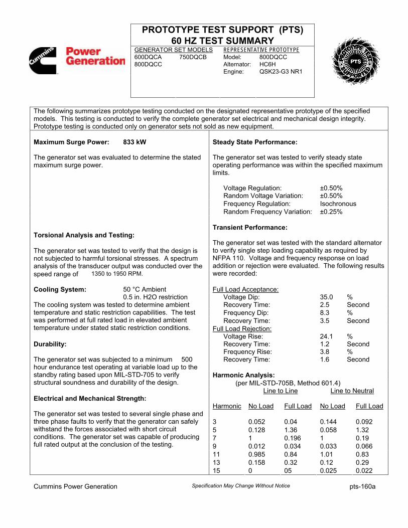
PROTOTYPE TEST SUPPORT (PTS) 60 HZ TEST SUMMARY
GENERATOR SET MODELS REPRESENTATIVE PROTOTYPE 600DQCA 750DQCB Model: 800DQCC 800DQCC Alternator: HC6H Engine:
QSK23-G3 NR1
The following summarizes prototype testing conducted on the designated representative prototype of the specified models. This testing is conducted to verify the complete generator set electrical and mechanical design integrity. Prototype testing is conducted only on generator sets not sold as new equipment. Maximum Surge Power: 833 kW Steady State Performance: The generator set was evaluated to determine the stated maximum surge power.
The generator set was tested to verify steady state operating performance was within the specified maximum limits.
Voltage Regulation: ±0.50% Random Voltage Variation: ±0.50% Frequency Regulation: Isochronous Random Frequency Variation: ±0.25%
Transient Performance: Torsional Analysis and Testing: The generator set was tested to verify that the design is not subjected to harmful torsional stresses. A spectrum analysis of the transducer output was conducted over the speed range of 1350 to 1950 RPM.
The generator set was tested with the standard alternator to verify single step loading capability as required by NFPA 110. Voltage and frequency response on load addition or rejection were evaluated. The following results were recorded:
Cooling System: 50 °C Ambient Full Load Acceptance: 0.5 in. H2O restriction Voltage Dip: 35.0 %
Recovery Time: 2.5 Second Frequency Dip: 8.3 % Recovery Time: 3.5 Second
The cooling system was tested to determine ambient temperature and static restriction capabilities. The test was performed at full rated load in elevated ambient temperature under stated static restriction conditions. Full Load Rejection: Voltage Rise: 24.1 % Durability: Recovery Time: 1.2 Second Frequency Rise: 3.8 % The generator set was subjected to a minimum 500 Recovery Time: 1.6 Second
Harmonic Analysis:
hour endurance test operating at variable load up to the standby rating based upon MIL-STD-705 to verify structural soundness and durability of the design. (per MIL-STD-705B, Method 601.4) Line to Line Line to Neutral Electrical and Mechanical Strength: Harmonic No Load Full Load No Load Full Load
3 0.052 0.04 0.144 0.092 5 0.128 1.36 0.058 1.32 7 1 0.196 1 0.19 9 0.012 0.034 0.033 0.066 11 0.985 0.84 1.01 0.83 13 0.158 0.32 0.12 0.29
The generator set was tested to several single phase and three phase faults to verify that the generator can safely withstand the forces associated with short circuit conditions. The generator set was capable of producing full rated output at the conclusion of the testing.
15 0 05 0.025 0.022 Cummins Power Generation Specification May Change Without Notice pts-160a

This Page Left Intentionally Blank

ALTERNATOR DATA SHEET Frame Size: HC6HCHARACTERISTICS
WEIGHTS:
EXCITATION CURRENT:
INSULATION SYSTEM:
Wound Stator AssemblyRotor AssemblyComplete Alternator
Full Load
Class H Throughout
Amps2.5
lb2109lb1911lb4451
kg950kg861kg2005
No Load Amps0.5
MAXIMUM SPEED: rpm2250
3 Ø RATINGS (0.8 power factor) 60 Hz
240/416
795994
750938
690863
8701088
8201025
730913
50 Hz
220/380 254/440240/415
768960
728910
664830
768960
728910
664830
736920
700875
640800
(Based on specified temperature rise at 40ºC ambient temperature)
150ºC Rise Ratings
125ºC Rise Ratings
105ºC Rise Ratings
kWkVA
kWkVA
kWkVA
220/380110/190* 120/208*
277/480
9501188
9001125
8201025
139/240*347/600
9001125
8501063
770963
110/190* 120/208* 127/220*
REACTANCES (per unit, ±10%)
(Based on full load at 125ºC Rise Rating 240/416
3.660.290.210.250.03
3.340.270.190.230.03
220/380110/190* 120/208*
220/380 254/440240/415
2.980.280.200.210.03
2.500.230.160.180.02
2.140.200.140.150.02
277/480
2.750.220.160.190.02
139/240*347/600
2.600.210.150.180.02
110/190* 120/208* 127/220*
SynchronousTransientSubtransientNegative SequenceZero Sequence
MOTOR STARTING Broad Range Broad Range600
Maximum kVA (90% Sustained Voltage) 3313 3313 2250
Broad Range Broad Range600
0.1850.025
0.1850.025
0.1850.025
TIME CONSTANTSTransientSubtransientOpen circuitDC
2.4400.040
2.4400.040
2.4400.040
Broad Range Broad Range600
0.00601.4700
0.00721.4700
0.00601.4700
WINDINGSStator ResistanceRotor ResistanceNumber of Leads 6 (12 Optional) 6 6 (12 optional)
(Sec)
(@ 20ºC )
(Line to Line, Ohms)( Ohms)
80ºC Rise Ratings kWkVA
575719
632790
720900
592740
592740
590738
680850
ADS - 310D
* 12 lead reconnectible option is required to obtain low (parallel wye) voltages.
Cummins Power Generation Specification May change WIthout Notice.


NEWAGE INTERNATIONAL
THERMAL DAMAGE CURVE
1.00
10.00
100.00
1000.00
10000.00
1 2 3 4 5 6 7 8
FAULT CURRENT (per unit)
MA
XIM
UM
DU
RA
TIO
N O
F FA
ULT
(sec
)
THERMAL DAMAGE CURVE
The curve is drawn for the following conditions
a) 1 per unit current is referred to class F rating at minimum volts. b) Windings are assumed to be either hot or cold in an ambient of 30C. c) For overload and short circuit capacities of each frame, refer to sales literature. d) Once tripped, the Newage protection unit takes 8 - 10 sec to operate, irrespective of stator overload current value, it should therefore be regarded only as a BACK-UP to whatever system the customer chooses to install. It is ADVISABLE for customer to provide independent means of protection for overload current up to 3 per unit. It is IMPERATIVE to provide separate protection beyond 3 per unit in order to cover for L-L or L-N short circuits.
e) The curve is intended only as a guidance towards selection of protective devices and values taken from it should not be taken as absolute or guaranteed.
1 hour
30 min
10 min
5 min
2 min
1 min
10 sec

NE
WA
GE
IN
TE
RN
AT
ION
AL
A.C
. G
EN
ER
AT
OR
FR
AM
EH
C6
H
TH
RE
E P
HA
SE
PH
AS
E S
HO
RT
CIR
CU
IT D
EC
RE
ME
NT
CU
RV
E
A.V
.R T
YP
EM
XW
IND
ING
31
1 /
31
24
PO
LE
FR
EQ
60
Hz
18
00
Re
v/M
in
SE
RIE
S S
TA
R (
WY
E)
CO
NN
EC
TIO
NN
O L
OA
D E
XC
ITA
TIO
N A
T R
AT
ED
SP
EE
D
SU
ST
AIN
ED
SH
OR
T C
IRC
UIT
=4
10
0A
MP
SN
OT
E 1
NO
TE
2
TH
E F
OL
LO
WIN
G M
UL
TIP
LIC
AT
ION
FA
CT
OR
S S
HO
UL
D B
E U
SE
D T
O A
DJU
ST
TH
E V
AL
UE
ST
HE
FO
LL
OW
ING
MU
LT
IPL
ICA
TIO
N F
AC
TO
RS
SH
OU
LD
BE
US
ED
TO
CO
NV
ER
T T
HE
FR
OM
CU
RV
ES
BE
TW
EE
N T
HE
0.0
01
SE
CO
ND
S A
ND
TH
E M
INIM
UM
CU
RR
EN
T P
OIN
T I
NV
AL
UE
S C
AL
CU
LA
TE
D I
N A
CC
OR
DA
NC
E W
ITH
NO
TE
1 T
O T
HO
SE
AP
PLIC
AB
LE
RE
SP
EC
T O
F N
OM
INA
L O
PE
RA
TIN
G V
OL
TA
GE
T
O T
HE
VA
RIO
US
TY
PE
S O
F S
HO
RT
CIR
CU
IT
VO
LT
AG
EF
AC
TO
R3
PH
AS
E2
PH
AS
E L
- L1
PH
AS
E L
-N
416 V
X 1
.00
INS
TA
NT
AN
EO
US
X 1
.0X
0.8
7X
1.3
440 V
X 1
.06
MIN
IMU
MX
1.0
X 1
.80
X 3
.20
460 V
X 1
.12
SU
ST
AIN
ED
X 1
.0X
1.5
0X
2.5
0
480 V
X 1
.17
MA
X S
US
TA
INE
D D
UR
AT
ION
10
SE
C5
SE
C2
SE
C
TH
E S
US
TA
INE
D C
UR
RE
NT
VA
LU
E I
S C
ON
ST
AN
T I
RR
ES
PE
CT
IVE
OF
VO
LT
AG
E L
EV
EL
AL
L O
TH
ER
TIM
ES
AR
E U
NC
HA
NG
ED
AP
PLIC
AT
ION
DA
TA
SH
EE
T N
UM
BE
RH
C6H
/311 / 3
12/6
0/M
X/5
ISS
UE
AD
AT
E3/1
4/2
001
10
00
10
00
0
10
00
00 0
.00
10
.01
0.1
11
0T
IME
(s
ec
s)
CURRENT (Amps)
SY
MM
ETR
ICA
L
AS
YM
ME
TR
ICA
L

POWERPACT® P-Frame Molded CaseCircuit Breakers (Standard or 100% rated up to 1200A)
POWERPACT Molded Case Circuit Breakers lead the industry with proven, reliable protection and innovative design. Providingunparalleled performance and control, this generation of P-framecircuit breakers features exclusive MICROLOGIC® TripUnits, which allow for a range of sophisticated applications formetering and monitoring. In addition, units can be interchanged toallow for maximum flexibility and are field-installable for easyupgrades as needed.
The circuit breakers are available in 100%rated construction up to 1200 A to meet a broad range ofcommercial and industrial application needs.
Full-Featured Performance
■ P-frame – 1200A available in both standard and 100% ratingswith sensor sizes 250–1200A. Interrupting ratings (AIR)
J-65kAIR at 480 VAC ■ MICROLOGIC 3.0 Trip Unit
The most compact and innovative molded case circuit breakers
P-Frame 1200 A
KP91 - PJ800 AMP MCCB MICROLOGIC 3.0 LI TRIP UNIT ADJ. RATING PLUG TYPE-F 672 TO 800 AMP TRIP SET @ 800 AMP (LT - Ir = 1)
LEFT SIDE MOUNTED

Onboard Intelligence
For “smarter breakers,” a range of MICROLOGIC® Trip Unitsprovides advanced functionality, such as a communicationsinterface, and power metering and monitoring capabilities.With the appropriate MICROLOGIC Trip Unit, you cancommunicate with breakers, gather power information,monitor events and remotely control breakers based onpredetermined conditions, leading to substantial savings inelectrical system operating costs.
These interchangeable, microprocessor-controlled, plug-indevices provide the next generation of protection, measure-ment and control functions, delivering not only greaterelectrical system safety but also improved system integrationand coordination.
MICROLOGIC® Trip Units
Order Number 0612HO0201© 2002 Schneider Electric All rights reserved
Contact your Square D sales representative for additional information. Or, visit www.SquareD.com.
MICROLOGIC 3.0 and 5.0■ Basic circuit protection including
long-time, instantaneous and optionalshort-time adjustments
MICROLOGIC 3.0A, 5.0A and 6.0A■ Long-time, instantaneous and optional
short-time adjustments■ Integrated ammeter and phase
loading bar graph■ LED trip indicator■ Zone selective interlocking with
downstream and upstream breakers■ Optional ground-fault protection■ Optional MODBUS® communications
interface
MICROLOGIC 5.0P and 6.0P■ Long-time, instantaneous and optional
short-time adjustments■ Advanced relay protection (current
imbalance, under/over voltage, etc.)■ Inverse Definite Minimum Time Lag
(IdmtL) long-time delay curve shapingfor improved coordination
■ Basic power metering and monitoringfunctions
■ Standard MODBUS communicationsinterface compatibility withPOWERLOGIC® installations
■ Standard GF alarm on 5.0P.6.0P has equipment ground-faulttripping protection
MICROLOGIC 5.0H and 6.0H■ All 5.0P and 6.0P functions■ Enhanced POWERLOGIC power
metering and monitoring capabilities■ Basic power quality (harmonic)
measurement■ Waveform capture
POWERPACT® P-Frame Molded Case Circuit Breakers (Standard or 100% rated up to 1200 A)

200
300
400
500
600
7008009001000
.015
.02
.03
.04
.05
.06
.07
.08
.09
.1
.15
.2
.3
.4
.5
.6
.7
.8
.91
1.5
2
3
4
5
6
78910
15
20
30
40
50
60
708090100
CYCLE
150
24
2012
.5
8
42
1
16
24
16
LONG-TIME DELAYSECONDS AT 6 x Ir
1. There is a thermal-imaging effect that canto shorten the long-time delay. The thermimaging effect comes into play if a currenabove the long-time delay pickup value efor a time and then is cleared by the trippa downstream device or the circuit breakitself. A subsequent overload will cause tcircuit breaker to trip in a shorter time thanormal. The amount of time delay reductiinverse to the amount of time that has elasince the previous overload. Approximateminutes is required between overloads tocompletely reset thermal-imaging.
2. The end of the curve is determined by theinstantaneous setting.
3. Total clearing times shown include theresponse times of the trip unit, the circuitbreaker opening, and the extinction of thecurrent.
4. See 613-8 for instantaneous pickup trip
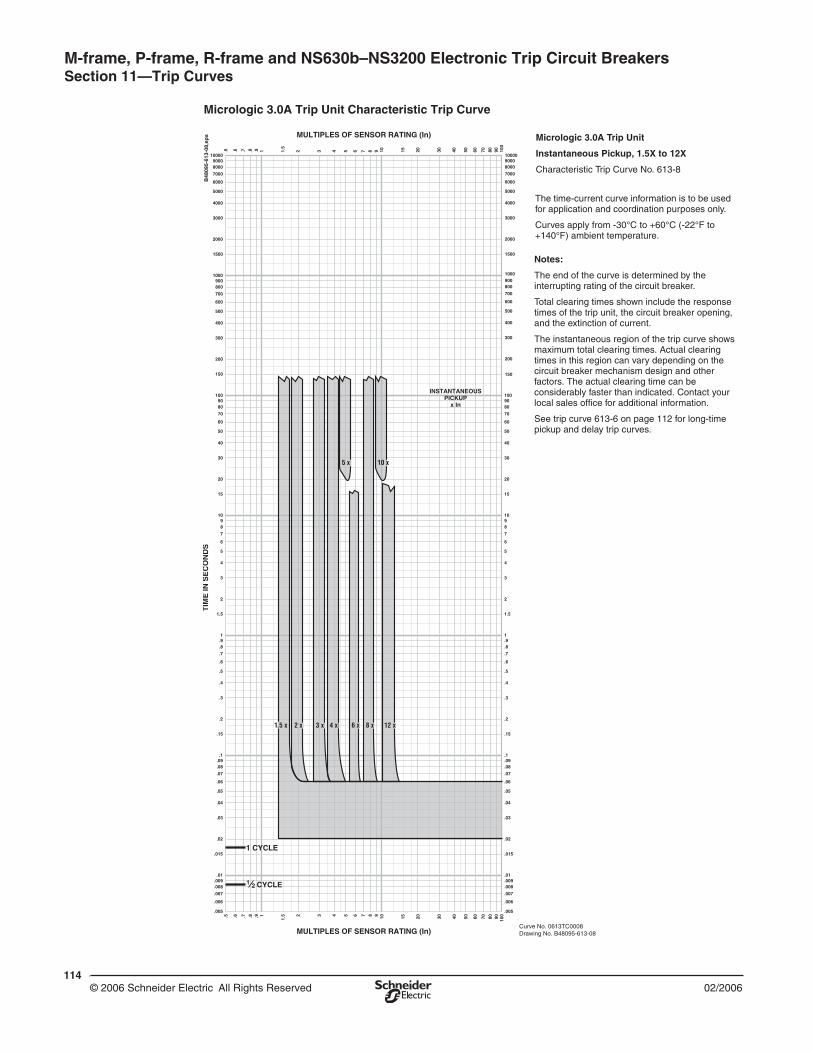
114© 2006 Schneider Electric All Rights Reserved 02/2006
M-frame, P-frame, R-frame and NS630b–NS3200 Electronic Trip Circuit Breakers Section 11—Trip Curves
Micrologic 3.0A Trip Unit Characteristic Trip Curve
1.51
1
MULTIPLES OF SENSOR RATING (In)
MULTIPLES OF SENSOR RATING (In)
.5 .6 .7 .8 .9 1.5
2 3 4 5 6 7 8 9 10 15 20 30 40 50 60 70 80 90 100
.5 .6 .7 .8 .9 2 3 4 5 6 7 8 9 10 15 20 30 40 50 60 70 80 90 100
200
300
400
500
600
700
8009001000
1500
2000
3000
4000
6000
7000
80009000
5000
10000
.005
.006
.007
.008
.009.01
.015
.02
.03
.04
.05
.06
.07
.08
.09.1
.005
.006
.007
.008
.009
.01
.015
.02
.03
.04
.05
.06
.07
.08
.09
.1
.15
.2
.3
.4
.5
.6
.7
.8
.91
.15
.2
.3
.4
.5
.6
.7
.8
.91
1.5
2
3
4
5
6
7
89
10
1.5
2
3
4
5
6
7
8910
15
20
30
40
50
60
70
8090
100
15
20
30
40
50
60
70
8090100
150
200
300
400
500
600
700
800900
1000
1500
2000
3000
4000
5000
6000
7000
80009000
10000
TIM
EIN
SE
CO
ND
S
CYCLE21
1 CYCLE
150
1.5 x
INSTANTANEOUSPICKUP
x In
5 x 10 x
2 x 3 x 4 x 6 x 8 x 12 x
Curve No. 0613TC0008Drawing No. B48095-613-08
Micrologic 3.0A Trip Unit
Instantaneous Pickup, 1.5X to 12X
Characteristic Trip Curve No. 613-8
The time-current curve information is to be used for application and coordination purposes only.
Curves apply from -30°C to +60°C (-22°F to +140°F) ambient temperature.
Notes:
The end of the curve is determined by the interrupting rating of the circuit breaker.
Total clearing times shown include the response times of the trip unit, the circuit breaker opening, and the extinction of current.
The instantaneous region of the trip curve shows maximum total clearing times. Actual clearing times in this region can vary depending on the circuit breaker mechanism design and other factors. The actual clearing time can be considerably faster than indicated. Contact your local sales office for additional information.
See trip curve 613-6 on page 112 for long-time pickup and delay trip curves.
B48
095-
613-
08,e
ps

116© 2006 Schneider Electric All Rights Reserved 02/2006
M-frame, P-frame, R-frame and NS630b–NS3200 Electronic Trip Circuit Breakers Section 11—Trip Curves
Table 72: Instantaneous Override Values Characteristic Trip Curve
UL/IEC Circuit BreakerInstantaneous Override1
(kA RMS)
1 Note: Faults at or above instantaneous override value will be cleared at 25 msec or less.
PJ 800 10 ± 10%
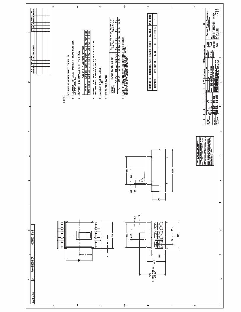

PowerPact® H-FrameCircuit Breakers in 15A to 150A
Circuit Breakers for Control Panel ApplicationsDesigned to address the unique demands of panel builders,PowerPact H-frame Molded Case Circuit Breakers give youthe right combination of features and performance to satisfy yourcircuit breaker requirements. PowerPact circuit breakers deliverunmatched design flexibility across the entire range of 15A to 150Aframe sizes offering the benefits of a flexible, modular circuit breakerthat panel builders demand.
Design standardization enables panel builders to improve theirproductivity so when specifications change, the panel design canremain the same. Thoughtful features that make this possibleinclude:
Common mounting dimensions (shown left) across the rangesaves time, so that although specifications may change, thecircuit breaker location remains the same.
Common accessories, actuators and trim dimensions across therange increases flexibility to meet specification changes.
Field-installable trip units and accessories allow for late cyclemodifications to the circuit breaker for after-the-fact flexibility.
Snap-in terminals can provide terminal solutions for a broadrange of control panels for increased productivity.
PowerPact H-Frame Circuit Breakers come in many interruptionratings and are designed to limit let-through currents to provide better protection for downstream components.
These circuit breakers are also certified to global standardsincluding UL, IEC, CSA and NOM offering you the ability to complywith local standards wherever that might be.
Volts "G"
240V 65kA
480V 35kA
600V 18kA
H-Frame 15-150A HG
UL 489 Interruption Ratings
Common mounting dimensions across theentire range means that the mountingpattern never has to change even whenpanel designs change. Shown above: A H-Frame Powerpact Circuit Breaker.
150 AMP H-FRAME SET @ 125 AMP TRIP
RIGHT SIDE MOUNTED - LIFE SAFETY

Powerpact® H- and J-frame Circuit BreakersSection 6—Trip Curves
4307/2005 © 2004–2005 Schneider Electric All Rights Reserved
110-150 A — HD, HG, HJ, and HL
1.5
700
150
200
300
400
600
800
900
2000
3000
4000
5000
7000
8000
9000
1000
0.5 .6 .7 .8 .9 1 2 3 4 5 6 7 8 9 10 15 20 30 40 50 60 70 80 90 100
6000
1500
1000500
.005
.006
.007
.008
.009
.01
.015
.02
.03
.04
.05
.06
.07
.08
.09
.1
.15
.2
.3
.4
.5
.6
.7
.8
.91
1.5
2
3
4
5
6
7
8910
20
30
40
50
60
70
8090100
15
200
300
400
500
600
700
8009001000
1500
2000
3000
4000
6000
7000
80009000
5000
10000
1.5 .6 .7 .8 .9 1.5
2 3 4 5 6 7 8 9 10 15 20 30 40 50 60 70 80 90 100
MULTIPLES OF RATED CURRENT
TIM
E IN
SE
CO
ND
S
.005
.006
.007
.008
.009.01
.015
.02
.03
.04
.05
.06
.07
.08
.09.1
.15
.2
.3
.4
.5
.6
.7
.8
.91
1.5
2
3
4
5
6
7
89
10
15
20
30
40
50
60
70
8090
100
150
200
300
400
500
600
700
800900
1000
1500
2000
3000
4000
5000
6000
7000
80009000
10000
TIM
E IN
SE
CO
ND
S
1/2 CYCLE(60 Hz)
1/2 CYCLE(50 Hz)
150
200
300
400
500
600
700
800
900
1000
1500
2000
3000
4000
5000
6000
7000
8000
9000
1000
0
150
MULTIPLES OF RATED CURRENT
1 CYCLE(60 Hz)
1 CYCLE(50 Hz)
MAXIMUM CLEARING TIME(AT 50 Hz) (AT 60 Hz)
110125
150
MAXIMUM SINGLE-POLE TRIP TIMESAT 25°C BASED ON NEMA AB-4 2003
150 A
125 A
110 A
HD, HG, HJ, HL MOLDED CASE CIRCUIT BREAKERSCHARACTERISTIC TRIP CURVE NO. 50-4
CIRCUIT BREAKER INFORMATION
Circuit Breaker Continuous Maximum NumberPrefix Ampere Rating AC Voltage of Poles
HD, HG, HJ, HL 110–150 600 2, 3
This curve is to be used for application and coordination purposes only. TheEZ-AMP overlay feature at the bottom of the page should be used duringcoordination studies.
All time/current characteristic curve data is based on 40°C ambient cold start.Terminations are made with conductors of appropriate length and ratings.
Curve No. 0050TC0404June 2004
Drawing No. 48095-050-04
TM
© 2004 Schneider Electric All Rights Reserved

Powerpact® H- and J-frame Circuit BreakersSection 6—Trip Curves
4507/2005 © 2004–2005 Schneider Electric All Rights Reserved
H-frame 150 A (HD, HG, HJ, and HL)
20 30 40 50 60 70 80 9010.2
.3
.4
.5
.6
.7
.8
.9
200100
2
1
Available Short Circuit Current (RMS Symmetrical Amperes x 103)
Curve No. 50-6
Typ
ical
* L
et-T
hro
ug
h I2 t
(A
mp
eres
2 S
eco
nd
s x
106 )
*B
ased
on
typi
cal v
alue
s ob
tain
ed th
roug
hout
the
circ
uit b
reak
er d
evel
opm
ent a
nd U
L te
st p
rogr
ams.
I2t
20 30 40 50 60 70 80 90106
7
8
9
10
200100
20
30
40
50
60
Available Short Circuit Current (RMS Symmetrical Amperes x 103)
Typ
ical
* P
eak
Let
-Th
rou
gh
Cu
rren
t (A
mp
eres
x 1
03 )
Curve No. 50-7
*Bas
ed o
n ty
pica
l val
ues
obta
ined
thro
ugho
ut th
e ci
rcui
t bre
aker
dev
elop
men
t and
UL
test
pro
gram
s.
Ip
240 V
J
D
D
D
G
GG
J
J
L
D
240 V
DD
G
G
G
J
J
J L
480 VL
600 VL
480 VL
600 VL
Maximum Available
Peak Currentat 25% Power Factor
Maximum Available
Peak Currentat 15% Power Factor
Curve No. 50-6 Let-Through I2tand 50-7 Peak Let-Through Current Ip


PowerPact® J-FrameCircuit Breakers in 150A to 250A
Circuit Breakers for Control Panel ApplicationsDesigned to address the unique demands of panel builders,PowerPact J-frame Molded Case Circuit Breakers give youthe right combination of features and performance to satisfy yourcircuit breaker requirements. PowerPact circuit breakers deliverunmatched design flexibility across the entire range of 150A to 250Aframe sizes offering the benefits of a flexible, modular circuit breakerthat panel builders demand.
Design standardization enables panel builders to improve theirproductivity so when specifications change, the panel design canremain the same. Thoughtful features that make this possibleinclude:
Common mounting dimensions (shown left) across the rangesaves time, so that although specifications may change, thecircuit breaker location remains the same.
Common accessories, actuators and trim dimensions across therange increases flexibility to meet specification changes.
Field-installable trip units and accessories allow for late cyclemodifications to the circuit breaker for after-the-fact flexibility.
Snap-in terminals can provide terminal solutions for a broadrange of control panels for increased productivity.
PowerPact J-Frame Circuit Breakers come in many interruptionratings and are designed to limit let-through currents to provide better protection for downstream components.
These circuit breakers are also certified to global standardsincluding UL, IEC, CSA and NOM offering you the ability to complywith local standards wherever that might be.
Volts "G"
240V 65kA
480V 35kA
600V 18kA
J-Frame 150-250A JG
UL 489 Interruption Ratings
Common mounting dimensions across theentire range means that the mountingpattern never has to change even whenpanel designs change. Shown above: A J-Frame Powerpact Circuit Breaker.
250 AMP J-FRAME SET @ 225 AMP TRIP
RIGHT SIDE MOUNTED - FIRE PUMP CB

44© 2004–2005 Schneider Electric All Rights Reserved 07/2005
Powerpact® H- and J-frame Circuit Breakers Section 6—Trip Curves
150-250 A — JD, JG, JJ, and JL
1.5
700
150
200
300
400
600
800
900
2000
3000
4000
5000
7000
8000
9000
1000
0.5 .6 .7 .8 .9 1 2 3 4 5 6 7 8 9 10 15 20 30 40 50 60 70 80 90 100
6000
1500
1000500
.005
.006
.007
.008
.009
.01
.015
.02
.03
.04
.05
.06
.07
.08
.09
.1
.15
.2
.3
.4
.5
.6
.7
.8
.91
1.5
2
3
4
5
6
7
8910
20
30
40
50
60
70
8090100
15
200
300
400
500
600
700
8009001000
1500
2000
3000
4000
6000
7000
80009000
5000
10000
1.5 .6 .7 .8 .9 1.5
2 3 4 5 6 7 8 9 10 15 20 30 40 50 60 70 80 90 100
MULTIPLES OF RATED CURRENT
TIM
E IN
SE
CO
ND
S
.005
.006
.007
.008
.009.01
.015
.02
.03
.04
.05
.06
.07
.08
.09.1
.15
.2
.3
.4
.5
.6
.7
.8
.91
1.5
2
3
4
5
6
7
89
10
15
20
30
40
50
60
70
8090
100
150
200
300
400
500
600
700
800900
1000
1500
2000
3000
4000
5000
6000
7000
80009000
10000
TIM
E IN
SE
CO
ND
S
1/2 CYCLE(60 Hz)
1/2 CYCLE(50 Hz)
150
200
300
400
500
600
700
800
900
1000
1500
2000
3000
4000
5000
6000
7000
8000
9000
1000
0
150
MULTIPLES OF RATED CURRENT
1 CYCLE(60 Hz)
1 CYCLE(50 Hz)
LIMITS HIGHSETTING
LIMITS LOWSETTING
MAGNETIC TRIPADJUSTMENT RANGE
MAXIMUM CLEARING TIME(AT 50 Hz) (AT 60 Hz)
225
200
150
250 17
5MAXIMUM SINGLE-POLE TRIP TIMESAT 25°C BASED ON NEMA AB-4 2003
JD, JG, JJ, JL MOLDED CASE CIRCUIT BREAKERSCHARACTERISTIC TRIP CURVE NO. 50-5
CIRCUIT BREAKER INFORMATION
Circuit Breaker Continuous Maximum NumberPrefix Ampere Rating AC Voltage of Poles
JD, JG, JJ, JL 150–250 600 2, 3
This curve is to be used for application and coordination purposes only. TheEZ-AMP overlay feature at the bottom of the page should be used duringcoordination studies.
All time/current characteristic curve data is based on 40°C ambient cold start.Terminations are made with conductors of appropriate length and ratings.
Curve No. 0050TC0405June 2004
Drawing No. 48095-050-05
TM
© 2004 Schneider Electric All Rights Reserved
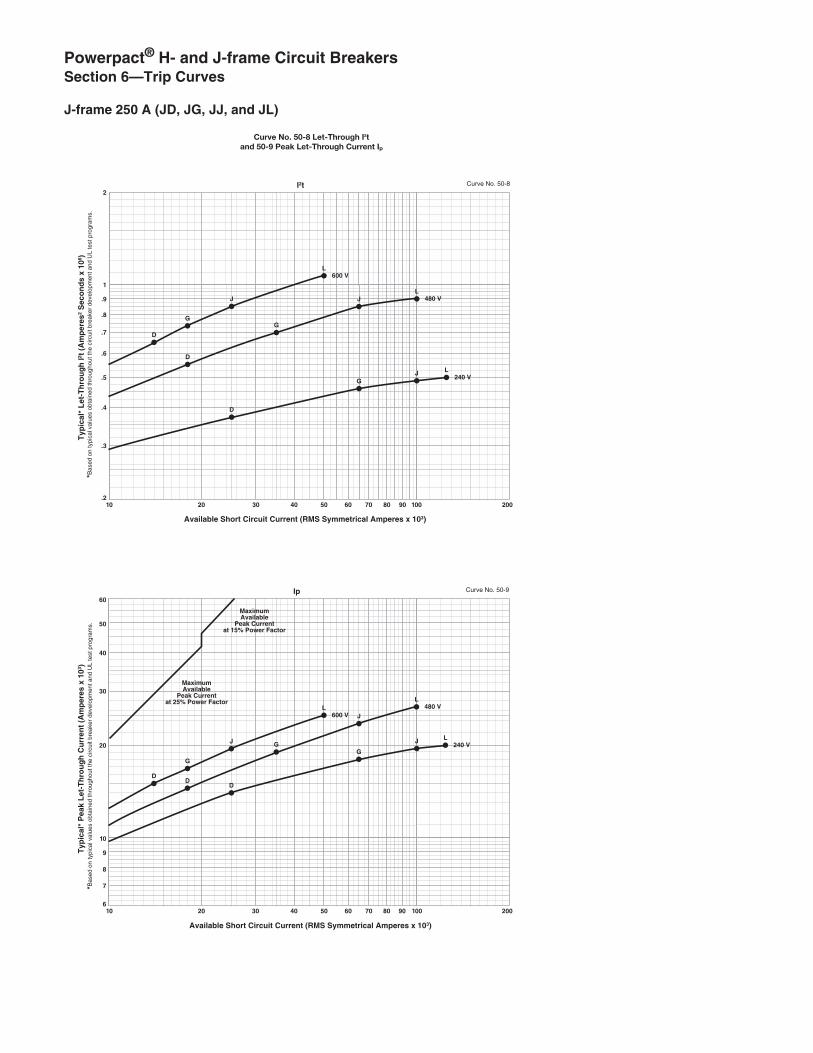
46© 2004–2005 Schneider Electric All Rights Reserved 07/2005
Powerpact® H- and J-frame Circuit Breakers Section 6—Trip Curves
J-frame 250 A (JD, JG, JJ, and JL)
20 30 40 50 60 70 80 9010.2
.3
.4
.5
.6
.7
.8
.9
200100
2
1
Available Short Circuit Current (RMS Symmetrical Amperes x 103)
Curve No. 50-8
Typ
ical
* L
et-T
hro
ug
h I2 t
(A
mp
eres
2 S
eco
nd
s x
106 )
*B
ased
on
typi
cal v
alue
s ob
tain
ed th
roug
hout
the
circ
uit b
reak
er d
evel
opm
ent a
nd U
L te
st p
rogr
ams.
I2t
20 30 40 50 60 70 80 90106
7
8
9
10
200100
20
30
40
50
60
Available Short Circuit Current (RMS Symmetrical Amperes x 103)
Typ
ical
* P
eak
Let
-Th
rou
gh
Cu
rren
t (A
mp
eres
x 1
03 )
Curve No. 50-9
*Bas
ed o
n ty
pica
l val
ues
obta
ined
thro
ugho
ut th
e ci
rcui
t bre
aker
dev
elop
men
t and
UL
test
pro
gram
s.
Ip
D
240 V
Maximum Available
Peak Currentat 25% Power Factor
Maximum Available
Peak Currentat 15% Power Factor
J
D
D
G
GG
J
J
L
D
240 V
DD
GG
G
J
J
J L
480 VL
600 VL
480 VL
600 VL
Curve No. 50-8 Let-Through I2tand 50-9 Peak Let-Through Current Ip


The Smart Choice for Mission-Critical Engine Starting
• Fast, accurate, mission-critical charging – gives best starting reliability• 4-rate, temperature-compensated output – offers longest battery life• Replace nearly any charger – without planning ahead• Industry-first battery-fault alarm – helps dispatch service early• Lasting reliability – field MTBF > 1 million hours with industry-best warranty• IBC seismic certification – meets latest building codes, no installation delays
SE I S M I C
C
E R T I F I ED
IBC2006
2000 2003
www.sens-usa.com • [email protected] • Toll-free 866.736.7872 • 303.678.7500
NRGIntelligent Engine Start Battery Charger

Failure to start due to battery problems is the leading cause of inoperable engine generator sets.
SENS NRG battery charger maximizes starting system reliability while slashing genset servicing costs:
One NRG replaces almost any charger without extra site visits. Installers can select or change atany time 120, 208 or 240 volts AC input, 12 or 24-volt battery and output settings optimized for nearly any lead-acid or nickel cadmium battery.
Easy to understand user interface provides state-of-the-art system status – including digitalmetering, NFPA 110 alarms and a battery fault alarm that can send service personnel to the site before failure to start.
Batteries charged by NRG give higher performance and last longer. In uncontrolled environmentsprecision charging by SENS increases battery life and watering intervals 400% or more.
NRG meets all relevant industry standards – including UL, NFPA 110 and CE. Seismic Certification per International Building Code (IBC) 2000, 2003, 2006. All units are C-UL listed. 50/60 Hz units add CE marking to UL agency marks.
EnerGenius reliability technology built into every charger includes: • All-electronic operation with generous component de-rating• Disconnected/reversed/incorrect voltage battery alarm and protection• Protection of connected equipment against load dump transients • Widest temperature rating, and overtemperature protection• Superior lightning and voltage transient protection• Demonstrated field MTBF > 1 million hours• Standard 3-year warranty (10 years magnetics and power semiconductors) and available 10-year complete warranty with reimbursement of field service costs
Earn the best return on your charger investment – choose SENS NRG
NRG Battery Charger Benefits and Features

NRG SpecificationsAC InputVoltage 110-120/208-240 VAC, +10%, single phase, field selectableInput current 10A charger: 6.6/3.3 amps maximum 20A charger: 12.6/6.3 amps maximumFrequency 60 Hz +5% standard; 50/60 Hz +5% optionalInput protection 1-pole fuse, soft-start, transient suppression
Charger OutputNominal voltage ratings 12 or 24 volt nominalOptional voltage rating 12/24 volt, field selectableBattery settings Six discrete battery voltage programs - Low or high S.G. flooded - Low or high S.G. VRLA - Nickel cadmium 9, 10, 18, 19 or 20 cellsRegulation +0.5% (1/2%) line and load regulationCurrent 10 or 20 amps nominalElectronic current limit 105% rated output typical – no crank disconnect requiredCharge characteristic Constant voltage, current limited, 4-rate automatic equalizationTemperature compensation Enable or disable anytime, remote sensor optionalOutput protection Current limit, 1-pole fuse, transient suppression
User Interface, Indication and AlarmsDigital meter Automatic meter alternately displays output volts, amps4
Accuracy +2% volts, +5% ampsAlarms LED and Form C contact(s) per table:
Front panel status display
Standard4-rate charging
1. Alarms “1” available only on 10A charger2. Form C contact provides summary alarm of these conditions. BBHH chargers include this alarm configuration. Contacts rated 2A @ 30 VDC
3. Battery fault alarm indicates these fault conditions: - Battery disconnected - Battery polarity reversed - Mismatched charger battery voltage - Open or high resistance charger to battery connection - Open battery cell or excessive internal resistance4. Three-position jumper allows user to select from three display settings: alternating volts / amps (normal), constant volts, or constant amps
or .5A @ 125 VAC resistive.

ControlsAC input voltage select Field-selectable switchOptional 12/24-volt output select Field-selectable two-position jumper Battery program select Field-selectable six-position jumper Meter display select Field-selectable three-position jumperFast charger enable/disable Field-selectable two-position jumper Temp compensation enable Standard. Can be disabled or re-enabled in the fieldRemote temp comp enable Connect optional remote sensor to temp comp port
EnvironmentalOperating temperature -20C to +60C, meets full specification to +45COver temperature protection Gradual current reduction to maintain safe power device temperatureHumidity 5% to 95%, non-condensingVibration (10A unit) UL 991 Class B (2G sinusoidal)Transient immunity ANSI/IEEE C62.41, Cat. B, EN50082-2 heavy industrial, EN 61000-6-2Seismic Certification IBC 2000, 2003, 2006 Maximum Sds of 2.28 g
Agency StandardsSafety C-UL listed to UL 1236 (required for UL 2200 gensets), CSA standard 22.2
no. 107.2-M89 CE: 50/60 Hz units DOC to EN 60335Agency marking 60 Hz: C-UL-US listed 50/60 Hz: C-UL-US listed plus CE markedEMC Emissions: FCC Part 15, Class B; EN 50081-2 Immunity: EN 61000-6-2NFPA standards NFPA 70, NFPA 110. (NFPA 110 requires Alarms “C”)Optional agency compliance Units with Alarms “1” configuration available with additional compliance to
UL category BBHH and NFPA 20
ConstructionHousing/configuration Material: Non-corroding aluminum. Configuration options: • Fully enclosed: C-UL listed enclosure • Open frame: C-UL recognizedPackaging Open-frame and Slimline configurations only available in bulk OEM quantities and packagingDimensions See Drawings and Dimensions page for detailsPrinted circuit card Surface mount technology, conformal coatedCooling Natural convectionProtection degree Listed housing: NEMA-1 (IP20). Optional IP21 drip shield. Optional NEMA 3R enclosureDamage prevention Fully recessed display and controls Electrical connections Compression terminal blocks
Warranty Standard warranty Three year parts and labor warranty (10 years magnetics and power semiconductors) from date of shipmentOptional warranty If specified at time of order, warranty coverage can be increased to reimburse customer’s documented field service costs up to the original charger price or increased to 5 or 10 years with field service cost reimbursement. Contact the factory for full details
Optional features Input Input frequency, 50/60 Hz Remote temp comp sensor Recommended where battery and charger are in different locationsDrip shield meets s/b (IP21) Protects from dripping waterNEMA 3R housing Enables outdoor installation (remote temp sensor recommended)UL BBHH listing Available in 10A units with Alarms “1”Field service warranty Reimbursement of customer field service expenses up to charger price for 3, 5, or 10 years
Simple field adjustments

Drawings and Dimensions
10A Chargers
20A Chargers

Contact InformationFor information and service on any SENS product, please contact us at:Sales 1.866.736.7872 • 303.678.7500 • Fax 303.678.7504www.sens-usa.com • [email protected] Industrial Circle, Longmont, CO 80501 USA
The Smart Choice for Mission-Critical Engine Starting
Output voltage12: 12 volts24: 24 volts22: 12/24-volt field selectable
Model Output current10: 10 amps20: 20 amps
AC inputR: 120/208-240 VAC, 60 HzH: 120/208-240 VAC, 50/60 Hz
Alarm system code1: LED and single Form C contactC: LEDs and Form C contacts to meet
NFPA 110
Housing/AgencyL: Enclosed: C-UL listed
UL category codeS: UL category BBGQ (standard)H: UL category BBHH (Alarms “1” only)
All models offer field-selectable input 120/208-240 volts. 60 Hz input is standard with C-UL listing. Optional 50/60 Hz input includes C-UL listing and adds CE mark.
111009 F
Additional InformationContact SENS or your local sales representative for additional specification, engineering and installation information. Check the SENS web site for latest available data. Specification is subject to change without notice.
SE I S M I C
C
E R T I F I ED
IBC2006
2000 2003
S2 2 1 0 R C L


Accessories For Multiple Battery Heating
Typical Connection - 2 Batterieson Each Side of Vehicle
100
80
60
40
20
0-20 0 +20 +40 +60 +80
Ambient Temperature, ˚F
Perc
ent
of B
atte
ry C
ran
kin
g P
ow
er
BatteryHeating Pads
A fully charged battery has only 40%cranking power at 0° F when compared to100% cranking power at 80° F.
When batteries are placed in an insulatedbattery box, a thermostat is recommended
to sense battery box temperature toprevent overheating the battery.
Battery heater not recommended fornickel cadmium batteries.
Standard Pad for Single Battery Special Pads for Multiple Batteries
B
A
Style C Style BStyle A
9.00REF TYP
9.00REF TYP
16-3 HPN
16-3 HPN
6" HPN
AA
BB
KB
7515
-D
KB
7515
-D
KB
7515
-D
KB
7515
-S
Left Side Battery Box Right Side Battery Box
BEC-6
BY-T68 BPC-61
Ground
2 FT4 FT6 FT8 FT
3 FT6 FT
16-3 HPN
15.375" 15.375"
15.375"
CORD, 16-3 HPN
36 Kim Hotstart Manufacturing Company, Inc. P.O. Box 11245 Spokane, WA 99211-0245
ModelNumber Volts Watts Amps
NominalDimensions Batt.
Size Style A B
KB5015KB5015-SKB5015-D
120120120
505050
.42
.42
.42
8 1/48 1/48 1/4
131313
4D4D4D
ABC
KB7515KB7515-SKB7515-D
120120120
757575
.63
.63
.63
10 1/210 1/210 1/2
18 1/219 1/219 1/2
8D8D8D
ABC
KB7523KB7523-SKB7523-D
240240240
757575
.31
.31
.31
10 1/210 1/210 1/2
18 1/219 1/219 1/2
8D8D8D
ABC
EXTENSION CORDSModel LengthBEC-2BEC-4BEC-6BEC-8
2’4’6’8’
POWER SUPPLY CORDSModel Length VoltsBPC-31BPC-32BPC-61BPC-62
3’3’6’6’
120240120240
THERMOSTAT & “Y” CORD ASSEMBLY
ModelTemperature ControlOn Off
BY-T68 60°F 80°F

Lube oil temperature controls hold lube oil at the desired temperature.
If the heater is energized while the engine is hot or running, Kim Hotstart recommendsusing thermostats with all lube oil heaters to protect the oil from overheating.
The sensing unit can be changed without draining the sump.
TemperatureControls
lube oil heaters
Class I, Group D Hazardous Location
Furnished with 18” of lead wire forconnection to the power leads in an
approved splice box.
Weathertight
Furnished with a 3 ft. 16/3 HPN powercord.
C US
3.375
1.625 1.75Probe Depth
.600
.5 NPT
3' 16-3HPN Cord
5.50
3.25 .600
1.625ProbeDepth
.5 Inch NPT
Weathertight Model Dimensions Class 1, Group Model Dimensions
Weathertight Model Number
Class I, Group D Model Number
Temp. Range
On Off
ThreadSize
SwitchCapacity
DIT68DIT810DIT1012DIT1214
DIT68EPDIT810EPDIT1012EPDIT1214EP
60°F 80°F80°F 100°F
100°F 120°F120°F 140°F
1/2” N.P.T.1/2” N.P.T.1/2” N.P.T.1/2” N.P.T.
120v - 15 amps208v - 10 amps240v - 10 amps277v - 10 amps
12v DC24v DC
PilotDutyOnly}
40 F 60 FDIT46

Keep your heavy-duty equipment operatingwith Deka Commercial Batteries.
Lyon Station, PA 19536-0147 • Phone: 610-682-6361 • Fax: 610-682-4781Order Department Hotline: 610-682-4231www.dekabatteries.com • E-mail: [email protected]
DISTRIBUTED BY:
RETU
RNLE
AD
RECYCLE
Pb
■ Special computer-aided designand manufacturing mean moredurability for heavy-duty line-haul trucks, buses, farm tractorsand off-road equipment.
■ Most of our commercial batteriescontain premium ”deep pocket“envelope separators, whichprotect the plates on all four sidesto dramatically reduce shortingand extend service life.
■ Genuine calcium lead alloyprovides longer waterlessoperation and extendedbattery life.
■ Anchor-locked elements withradial grid and tight-packcommercial plates resist thedamaging effects of vibration,delivering more power-per-poundthan other batteries.
■ Deka Commercial Batteries areavailable wet and many can beordered bone-dry. Our specialdry-charge process completelyeliminates moisture for virtuallyunlimited shelf life when comparedto inferior ”moist-dry“ types.
930H
904MF
94DLT
1231MF
908D
CO
MM
ERCIA
LBATTERIE
S
■ Most popular sizes feature toughpolypropylene cases which resistbreakage and extend service life.Many are also available withhandles and special terminals foreasy installation.
■ Deka offers the most completeline of enveloped calcium mainte-nance-free commercial batteriesin the industry. Our line includessuch hard-to-find group sizes as 3D.
■ More than 250 quality controlchecks ensure the highestquality.
“POWERED FOR PERFORMANCE ” ®

®
COMMERCIAL BATTERIES
E.P.M. Form No. 0010 Rev. 12/08©2008 by EPM Printed in U.S.A.
All data subject to change without notice.No part of this document may be copied or reproduced, electronically
or mechanically, without written permission from the company.
Ratings conform to B.C.I. specifications.
Dry = up to 10% reduced capacity.
All batteries are maintenance-free, calciumgrids except where noted.
All batteries manufactured in black polypropylenecases and covers except where noted.
FOOTNOTES:S - SAE “automotive type” postX - 3/8" x 16 stainless steel stud posts11 - Low maintenance – Low antimony grids12 - Hybrid construction15 - Hard rubber, one-piece cover construction17 - Includes handle19 - Includes lifting ledges20 - Hard rubber, multi-cell
cover construction
MEMBER:
AMERICANTRUCKING
ASSOCIATION
TECHNOLOGY &MAINTENANCE
COUNCIL
GROUPNO. PART NO. CCA
@ 0˚F RES. CAP. REF. CA.@ 32˚F
WARR.WET DRY
in mm.inmm.in mm.
PERFORMANCE LEVEL WEIGHTFOOTNOTESLENGTH WIDTH HEIGHT
HEAVY-DUTY COMMERCIAL SERVICE 8-VOLT COMMERCIAL SERVICE
1 801 520 102 650 24 31.5 19 87⁄8 225 63⁄4 171 87⁄8 225 12,25,30
HEAVY-DUTY COMMERCIAL SERVICE 6-VOLT HEAVY-DUTY COMMERCIAL SERVICE
1 901MF 650 180 815 30 33.5 18 9 229 67⁄8 175 83⁄4 222 21,25,30
2 902 780 200 940 30 36.5 — 103⁄8 264 67⁄8 175 83⁄4 222 12,25
3D 903DY 1400 675 1660 30 120 84 203⁄8 518 83⁄4 222 10 254 11,17,20,25,32
3EH 93EH 925 250 1095 30 47.5 — 191⁄4 489 41⁄4 108 10 254 12,25
4 904MF 1000 270 1220 30 47 — 121⁄2 3 67⁄8 175 91⁄2 241 21,25
5D 905D 880 300 1100 30 50 — 133⁄8 340 71⁄8 181 91⁄4 235 12,25
7D 907D 950 350 1120 30 59.5 34 153⁄4 400 7 178 91⁄8 232 11,25,31
7D907D95035011203059.53415-3/440071789-1/823211,25,31A-DUTY COMMERCIAL SERVICE12-VOLT HEAVY-DUTY COMMERCIAL SERVICE
3ET 93ET 500 120 625 30 48 — 191⁄4 489 41⁄4 108 97⁄8 251 12,25
4D904D 1050 290 1280 30 99.5 58
203⁄4 527 81⁄2 216 101⁄8 25812,17,25,31
804D 950 250 1160 30 97 — 12,17,25
4DLT 94DLT 900 240 1065 30 80 — 20 508 81⁄8 206 81⁄8 206 12,19,25
8D
908DMF 1500 450 1825 30 134 —
203⁄4 527 11 279 10 254
17,21,25
908D 1400 430 1700 30 130 80 12,17,25,31
708D 1100 325 1340 30 117.5 — 12,17,25
17TF 917TF 530 150 630 30 58.5 — 17 32 67⁄8 175 8 203 11,15,19,25
28 928MF 550 100 685 30 41.5 — 101⁄4 260 63⁄4 171 91⁄2 241 21,22,X
30H1130HMF 925 170 1110 30 57.5 —
13 330 63⁄4 171 91⁄2 24119,21,22
930H 650 145 810 30 51 — 19,21,22
1231MF 1125 195 1260 30 61 — 19,21,22,X
1131XMF 1000 185 1190 30 58 43 19,21,22,30,X
31 1131MF 925 170 1110 30 56.5 — 13 330 63⁄4 171 91⁄2 241 19,21,22,X
1031MF 760 170 910 30 54.5 — 19,21,22,X
931MF 650 145 810 30 51 — 19,21,22,X
1231PMF 1125 195 1260 30 61 — 19,21,22,S
1131XPMF 1000 185 1190 30 58 — 19,21,22,S
31P 1131PMF 925 170 1110 30 56.5 — 13 330 63⁄4 171 91⁄2 241 19,21,22,S
1031PMF 760 170 910 30 54.5 — 19,21,22,S
931PMF 650 145 810 30 51 — 19,21,22,S
75/86 7AG75DT 690EAVY-DUTY COMMERCIAL SERVICE12-VOLT HEAVY-DUTY COMMERCIAL SEVERE SERVICE–DUAL PURPOSE (W/ DOUBLE INSULATED GLASS MAT SEPARATORS)
31 7T31 730 190 940 30 62.5 — 19,21,22,43,X
31 DP31CS 700 180 875 30 57 — 13 330 63⁄4 171 91⁄2 241 19,21,22,43,X
31P DP31PCS 700 180 875 30 57 — 19,21,22,43,S
MAXIMUM OVERALL DIEMENSIONS
21 - Anchor lock elements22 - Flush manifold vented cover25 - With individual vent caps30 - Available dry-add “D” suffix to part number31 - Available dry-add “Y” suffix to part number32 - Available dry charge only43 - Warranty is 12 months in deep cycle service
XS

ACEMOUNT ®
ACE MOUNTINGS CO., INC. MP950003
Series 820 SPRING ISOLATORS For Seismic Zone 2 Applications
CATALOG NO. 94A-867-F
11 Cross Avenue South Amboy, NJ 08879 Tel: (732)721-6200 Fax: (732)721-5005 Email: [email protected] Website: www.acemount.com
Seismic Zone 2 Capability: The housings and anchor bolts are optimally designed for seismic zone 2 applications. Superior Isolation Efficiency: Series "820" spring isolators consist of welded housings and 1 inch deflection spring elements to provide excellent isolation of vibration over a wide frequency range. Lateral Stability: Free-standing springs are laterally stable and designed to provide 50% overload capacity. Vertical Limit Stops: Adjustable vertical limit stops control vertical and lateral movement of isolated equipment due to load change, and lateral seismic load. Easy To Install: Built-in leveling bolt eliminates shimming in all applications, and save installation costs. Effective Noise Reduction: The resilient washers under the springs effectively interrupt structure-borne noise transmission paths to prevent noise amplifications caused by sounding-board effect. The resilient washers replace the neoprene base pad to allow solid connections of anchor bolts and base plate.
Type "822" Type "821"
Material Specifications Housings: A-36 steel Threaded Parts: grade 5 steel Springs: ASTM-229, oil tempered wire Elastomer: neoprene rubber Made in USA

ACE MOUNTINGS CO., INC.
AA BB CC DD EE FF GG
821 11 4 4-1/2 8 6 5/8-11 x 4 UNC 11/16
822 14-1/2 4 6-1/4 11-1/2 6 5/8-11 x 4 UNC 11/16
824 14-1/2 6 6-1/4 12 6-1/2 ** 13/16
TYPE DIMENSIONS IN INCHES
A gray 150 300 600 1.5
B tan 260 520 1040 1.3
C yellow 435 870 1740 1.3
D green 550 1100 2200 1.1
E red 780 1560 3120 1.0
F silver 1070 2140 4280 1.0
G brown 1400 2800 5600 1.0
H black 1800 3600 7200 1.0
K blk & yel 2500 5000 10000 1.0
TYPE COLOR
OF SPRING
MAX. LOAD IN LBS. DEFLECTION IN
INCHES 824 822 821
GG
Lock nut Flat washer
CC CC
1/4
3/8
EE free & oper. hgt.
BB
AA
DD
1/4*
FF Leveling bolt
Resilient washer
Resilient grommet
Full nut
Jam nut
Vertical restraints 2.75 inch OD stable spring
Noise - reduction resilient washer
Gusset
821 single-spring unit 822 double-spring unit 824 four-spring unit
DIMENSIONS & LOAD CAPACITIES
Note: * Type 824 only.
1/4*
11 Cross Avenue South Amboy, NJ 08879 Tel: (732)721-6200 Fax: (732)721-5005 Email: [email protected] Website: www.acemount.com
** Available in 3/4-10 x 5 and 1-8 x 5

Closed Crankcase Ventilation (CCV)Installation Instructions for CCV4500, CCV6000, CCV8000, and CCV12000 Series Filters
Contact Information:Parker Hannifin CorporationRacor DivisionP.O. Box 32083400 Finch RoadModesto, CA 95353
phone 800 344 3286 209 521 7860
fax 209 529 [email protected]
www.racorcustomers.comwww.parker.com/racor
Overview:Contaminated crankcase emissions are a serious problem for diesel engine owners and the environment. These emissions are a result of gas escaping past piston rings due to high cylinder pressures into the crankcase. In the crankcase, gases are contaminated with oil mist, water, etc. These contaminated emissions escape through the engine breather into the engine compartment and engine intake system.
Racor CCV Systems offer an effective solution to reduce contaminated crankcase emissions. CCV systems remove crankcase emissions, providing protection for the engine and the environment.
Instruction Part Number 55021 Rev D
Product Features: Keeps engine compartments
and components clean
Prevents clogging of engine intakes, turbochargers, and intercoolers
Improves reliability and maintainability of diesel engines.
More efficient than other products available on the market
Reduces environmental pollution from crankcase emissions
Reduces smoke and odor in the immediate environment

Mounting Details
4500 Series 6000 Series 8000 Series 12000 Series
Dimension IN CM IN CM IN CM IN CM
A 7.2 18.3 8.6 21.8 10.6 26.9 10.6 26.9
B 5.6 14.2 7.3 18.5 9.3 23.6 9.3 23.6
C 5.6 14.2 7.1 18.0 9.1 23.1 9.1 23.1
D 7.5 19.1 11.3 28.7 13.3 33.8 13.3 33.8
E 6.0 15.2 7.5 19.1 9.5 24.1 9.5 24.1
F 9.3 23.6 12.0 30.5 13.9 35.3 18.0 45.7
G1 2.3 5.8 4.0 10.2 5.0 12.7 6.0 15.2
H 0.43 1.09 0.37 0.94 0.43 1.09 0.43 1.09
J2 N/A N/A 0.93 2.4 1.06 2.7 1.06 2.71 Dimension “G” is the minimum filter removal clearance - allow more room if possible for ease of service. 2 Dimension “J” is not applicable on CCV4500 assemblies because there are only two (2) mounting holes. All other units have four (4) mounting holes.
AWidth
BDepth
C
D
E
FHeight
G
J
H
CCV Dimensions
3
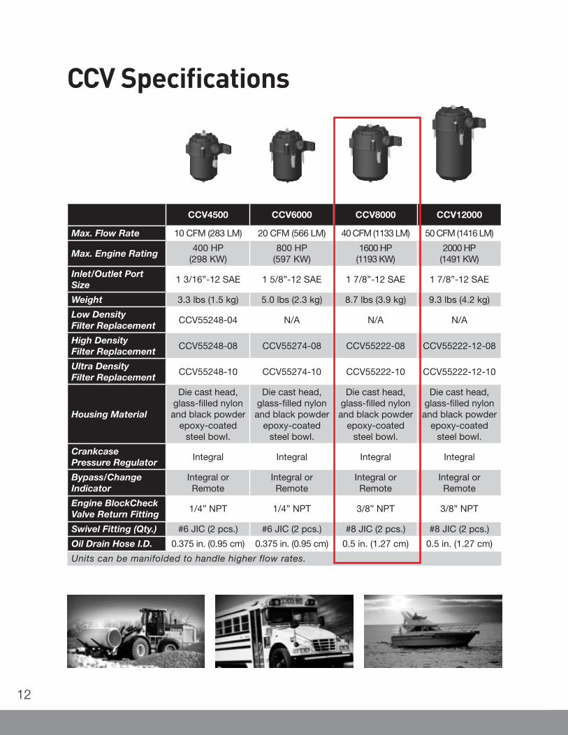
12
CCV4500 CCV6000 CCV8000 CCV12000
Max. Flow Rate 10 CFM (283 LM) 20 CFM (566 LM) 40 CFM (1133 LM) 50 CFM (1416 LM)
Max. Engine Rating400 HP
(298 KW)800 HP
(597 KW)1600 HP
(1193 KW)2000 HP
(1491 KW)
Inlet/Outlet Port Size
1 3/16”-12 SAE 1 5/8”-12 SAE 1 7/8”-12 SAE 1 7/8”-12 SAE
Weight 3.3 lbs (1.5 kg) 5.0 lbs (2.3 kg) 8.7 lbs (3.9 kg) 9.3 lbs (4.2 kg)
Low Density Filter Replacement
CCV55248-04 N/A N/A N/A
High Density Filter Replacement
CCV55248-08 CCV55274-08 CCV55222-08 CCV55222-12-08
Ultra Density Filter Replacement
CCV55248-10 CCV55274-10 CCV55222-10 CCV55222-12-10
Housing Material
Die cast head, glass-filled nylon and black powder
epoxy-coated steel bowl.
Die cast head, glass-filled nylon and black powder
epoxy-coated steel bowl.
Die cast head, glass-filled nylon and black powder
epoxy-coated steel bowl.
Die cast head, glass-filled nylon and black powder
epoxy-coated steel bowl.
Crankcase Pressure Regulator
Integral Integral Integral Integral
Bypass/Change Indicator
Integral or Remote
Integral or Remote
Integral or Remote
Integral or Remote
Engine BlockCheck Valve Return Fitting
1/4” NPT 1/4” NPT 3/8” NPT 3/8” NPT
Swivel Fitting (Qty.) #6 JIC (2 pcs.) #6 JIC (2 pcs.) #8 JIC (2 pcs.) #8 JIC (2 pcs.)
Oil Drain Hose I.D. 0.375 in. (0.95 cm) 0.375 in. (0.95 cm) 0.5 in. (1.27 cm) 0.5 in. (1.27 cm)
Units can be manifolded to handle higher flow rates.
CCV Specifications

This Page Left Intentionally Blank

��������
����
�� �� �� �� �� �
� �� �� �� � �� ���
� �� ��� �� ��� �� ��

This Page Left Intentionally Blank

ES Compleat™ EG is a high performance fully formulated Extended Life Ethylene GlycolAntifreeze/Coolant. It is Fleetguard’s answer to the maintenance demands of heavy-duty diesel cooling systems. ES Compleat™ EG can be used with ES Slow Release Filters or with ES Extender and only requires possible re-inhibition after 1 year, 150,000 miles (250,000 km), or4,000 hours of operation. It is the perfect mixture that protects your cooling system by preventing scaling, foaming, corrosion and liner pitting. ES Compleat™ is easy to use, cost effective, and outperforms other extended life products in the marketplace today.
CC2822 Bulk CC2827 BulkCC2823 275 Gal. Tote (1040 liters) CC2834 275 Gal. Tote (1040 liters)CC2821 55 Gal. Drum (208 liters) CC2826 55 Gal. Drum (208 liters)CC2847 5 Gal. Pail (18.9 liters) CC2848 5 Gal. Pail (18.9 liters)CC2820 1 Gal. Bottle (3.785 liters) CC2825 1 Gal. Bottle (3.785 liters)
ES Compleat™ Ethylene Glycol Concentrate ES Compleat™ Ethylene Glycol Premix 50/50
ES COMPLEAT™ EG Antifreeze/Coolant

ES COMPLEAT™ Antifreeze/CoolantETHYLENE GLYCOL CONCENTRATE & PREMIX
FLEETGUARD ES COMPLEAT™ EG Antifreeze/Coolants are Extended Life formulations that contain Ethylene Glycol base fluids and are designed specifically for Extended Service use in heavy-dutydiesel engines. ES COMPLEAT™ contains conventional heavy-duty chemical inhibitors and organic corro-sion inhibitors that provide enhanced diesel engine liner pitting protection and eliminates hard water scaledeposits. ES COMPLEAT™ products are formulated with the highest liner pitting protection available in themarketplace, with low TDS and silicate levels. ES COMPLEAT™ is specifically designed for use with ESSlow Release coolant filters or liquid ES Extender to provide simplified coolant maintenance while extendingcoolant service intervals to 12 months or 150,000 miles. ES COMPLEAT™ can also be used in standardservice maintenance intervals with the use of SCAs and standard coolant filters.
ES COMPLEAT ™ EG CONCENTRATE mixes readily with clean tap water or demineralized water, while ES COMPLEAT™ EG PREMIX is formulated with demineralized water and is ready to use. Both EG coolantproducts are low silicate, contain a full charge of heavy-duty chemical inhibitors, and are compatible with ESCoolant chemical filters and conventional SCA’s. ES COMPLEAT™ EG antifreezes are universal productshighly recommended for use in all Cummins and similar types of heavy-duty diesel engines, and also for usein automobile and light duty applications.
ES COMPLEAT™ EG ANTIFREEZE COOLANTS are considered Lifetime Coolants, meet or exceed the performance requirements of the following specifications, and meet the low silicate limits of GM6038Mantifreeze formulation requirements:
TMC RP 338 Extended Life Cummins CES 14603 NavistarTMC RP 329 Cummins SB 3666132 Freightliner 48-22880ASTM D-6210 Caterpillar VolvoASTM D-4985 Detroit Diesel 7SE298 PACCARASTM D-3306 John Deere 8650-5 Mack 014G817004CID-A-A-52624 Thermo-King EMD M.I. 1748EGM 1899 Case New Holland Waukesha 4-1974D
TYPICAL PROPERTIES EG EG EGConcentrate Premix 50/50 Premix 60/40
Color Visual Blue Blue BlueSpecific Gravity @ 60ºF D1122 1.13 1.07 1.09Pounds per Gallon ----- 9.43 8.93 9.07pH (Undiluted) D1287 10.5 10.5 10.5Reserve Alkalinity (Undiluted) D1121 10.0 5.0 min. 5.0 min.Freeze Point, ºF (Undiluted) D1177 8 min. -34 min. -65 min.Boiling Point, ºF (Undiluted) D1120 345 min. 226 min. 230 min.Water, wt % (Approx.) D1123 4.0 47.0 max. 37.0 max.Total Glycol, wt. % ----- 95.0 min. 51.0 min. 61.0 min.Glassware Corrosion Test D1384 Pass Pass PassWater Pump Cavitation Test D2809 Pass Pass PassAluminum Corrosion Test D4340 Pass Pass PassSimulated Service Test D2570 Pass Pass PassAsh Content, mass % D1119 5.0 max. 2.5 max. 2.5 max.Chloride wt% (ppm) -------- 25 max. 25 max. 25 max.
LT1554811/00
To order, call your Customer Assistance Representative at 1-800-22FILTER (1-800-223-4583),fax 1-800-999-8664 or visit us at www.fleetguard.com

EXTREMEEXTREME
SAEAPI CJ-4/ SM Heavy DutyDiesel Engine Oil
15W-40API CJ-4/ SM Heavy DutyDiesel Engine Oil
15W-40SAE
Premium Blue Extreme CJ-4 the latest HD high performance, low ash oil for extreme engine protection.
Premium Blue Extreme CJ-4 provides:
S Low ash levels and new high technology additives for extreme protection of your engine and advanced temperature performance.
S New dispersant formulation and shear stability polymers for enhanced viscosity control and temperature protection.
S Reduced emissions, a cleaner engine and improved deposit and soot management.
S Extreme lubrication for the latest generation of emissions compliant engines using either EGR or engine after-treatment. CJ-4 is recommended as the preferred oil for all ADR-80/02 emission compliant engines.

Features S Blended with high tech premium base oil.
S Formulated with high performance additive chemistry
S Formulated with unique high levels of dispersive technology, Shear stable VI polymers and detergent ‘over based’ technology
Performance benefits over CI-4/CI-4 Plus
- Reduced emissions - Superior high temperature antioxidancy - Enhanced soot and viscosity control - Enhanced low temperature pumpability - Lower volatility/ reduced oil consumption - Improved valve train wear protection - Improved ring and liner wear protection - Improved bearing protection - Improved piston deposit protection - Suitable for mixed fleet applications - Specifically formulated for Cummins engines
- Unique high levels of dispersive technology for better soot and viscosity control and superior wear protection.
- Shear stable VI polymers for consistency of viscosity – ‘stay in grade‘, low temperature pumpability and high temperature protection.
- Detergent ‘over based’ technology for improved piston deposit controls, a cleaner engine and superior TBN retention.
Protect Emissions
EquivalentShear Stability
ImprovedPiston Deposits
Better SootRelated ViscosityControl
ImprovedBearing Protection
CJ-4
CI-4 Plus
CI-4
Improved ValveTrain Protection
Lower volatility/ consumption
CJ-4 Performance Upgrade over CI-4/ CI-4 Plus
Meets or exceeds the following
test standards
- Cummins CES 20081 - Mack EO-O Premium Plus 07 - MTU Type 2 - DDC PGOS 93 K218
- MB 228.3 - ACEA E-7 - CAT ECF-3 - API CJ-4, CI-4+, CI-4 - API SM

2007 Cummins Power Generation Inc. All rights reserved Specifications subject to change without notice Cummins Power Generation and Cummins are registered trademarks of Cummins Inc. PowerCommand and “Our energy working for you.” are trademarks of Cummins Power Generation. Other company, product, or service names may be trademarks or service marks of others. S-1431c (9/07)
PowerCommand® Digital Input/output Module DIM - Base, DIM - Expansion
Description Features
The PowerCommand Digital Input/output Module (DIM) provides up to sixteen (16) output relays for local or remote monitoring and control of power system equipment such as motors, louvers, lamps, fans and pumps. The relays may be controlled as a group or individually by PowerCommand software or other system components. The DIM may be added at any point in the network using twisted-pair cabling.
DIM - Base contains eight (8) Form-C relay output sets and four (4) discrete dry contact inputs.
DIM - Expansion easily connects to DIM - Base to provide an additional eight (8) Form-C relay output sets for extended control and monitoring and (4) additional discrete dry contact inputs.
DIM - Expansion
Up to sixteen (16) Form-C latching relays provide easy control of system equipment such as lamps, louvers, motors and pumps.
Four (4) discrete dry contact inputs for monitoring equipment status. Equipment status may be shared with other network modules.
DIM - Base provides eight (8) Form-C contact output sets and four (4) discrete inputs.
DIM - Expansion provides an additional eight (8) output relays and (4) additional discrete inputs.
May be connected at any point in the PowerCommand Network.
Pluggable connectors allow easy one-time wiring.
Less wiring makes installation and system upgrades quick and easy.
May be remotely monitored and controlled with PowerCommand Software for Windows V 2.01.
PowerCommand Controls are supported by a worldwide network of independent distributors who provide parts, service and warranty support.
UL Listed and labeled; CSA certified; CE marked.

Our energy working for you.™
www.cumminspower.com
2007 Cummins Power Generation Inc. All rights reserved Specifications subject to change without notice Cummins Power Generation and Cummins are registered trademarks of Cummins Inc. PowerCommand and “Our energy working for you.” are trademarks of Cummins Power Generation. Other company, product, or service names may be trademarks or service marks of others. S-1431c (9/07)
Specifications
Signal requirements Relay ratings (DIM - Base)
Network connections: Echelon® LonWorks®, twisted-pair 78 kbps, FT-10
Control power: 10-36 VDC
Current: 100 mA typical
Wiring materials for network signals are UL Listed NEMA Level 4 twisted pair wiring. Terminations for control power accept wire up to 16 ga.
Environment
The DIM - Base and Expansion is designed for proper operation in ambient temperatures from -40 °C to +70 °C (-40 °F to +158 °F) and for storage from -40 °C to +80 °C (-40 °F to +176 °F). Control will operate with humidity up to 95%, non-condensing, and at altitudes up to 5000 m (13000 ft).
Revision A: 1 A @ 125 VAC, 2 A @ 30 VDC Revision 2 A: 2 A @ 250 VAC, 2 A @ 30 VDC
Relay ratings (DIM - Expansion) 1 A @ 125 VAC, 2 A @ 30 VDC
Network length: Maximum 1400 m (4600 ft)
Approved wiring: UTP NEMA Level 4, Cat 5 (stranded)
Dimensions
Ordering information
Part number Description
0541-0771 Digital Input/output Module - Base (DIM - Base), FT-10
0541-0772 Digital Input/output Module - Expansion (DIM - Expansion), FT-10
See your distributor for more information.
Cummins Power Generation
Americas 1400 73rd Avenue N.E. Minneapolis, MN 55432 USA Phone: 763 574 5000 Fax: 763 574 5298
Europe, CIS, Middle East and Africa Manston Park Columbus Ave. Manston Ramsgate Kent CT 12 5BF United Kingdom Phone 44 1843 255000 Fax 44 1843 255902
Asia Pacific 10 Toh Guan Road #07-01 TT International Tradepark Singapore 608838 Phone 65 6417 2388 Fax 65 6417 2399

2007 Cummins Power Generation Inc. All rights reserved Specifications subject to change without notice Cummins Power Generation and Cummins are registered trademarks of Cummins Inc. PowerCommand and “Our energy working for you.” are trademarks of Cummins Power Generation. Other company, product, or service names may be trademarks or service marks of others. S-1343e (9/07)
PowerCommand® Remote Annunciator Panel (LonWorks System annunciator)
Description Features
The PowerCommand® Network Annunciator is a network component that provides remote system status indication for emergency and other power systems in compliance to the requirements of NFPA 110. The network annunciator may also be used for remote indication of any condition that is monitored by a PowerCommand Network.
The Network Annunciator reduces installation costs and improves design flexibility by use of a PowerCommand Network to transmit all the genset and transfer switch system signals rather than using relay contacts for this purpose.
Control power for PowerCommand Network products is usually derived from the genset starting batteries. The control functions over a voltage range from 8 VDC to 35 VDC.
Visual indication of 20 network conditions and network status.
Audible indication of any network condition - Annunciator also includes pushbutton switch to silence the audible alarm. Alarm horn sound level is approximately 90 dB(A) at 30 cm.
Standard NFPA 110 label, field configurable for other alarm and status conditions.
Configurable for compliance to NFPA 99 requirements.
Sealed membrane panel design provides environmental protection for internal components and is easy to clean.
Warranty - PowerCommand Controls are supported by a worldwide network of independent distributors who provide parts, service and warranty support.
UL Listed and labeled; CSA certified; CE marked.
Wall mount NEMA 1 enclosure or flush mount configurations available.
x2

Our energy working for you.™
www.cumminspower.com
2007 Cummins Power Generation Inc. All rights reserved Specifications subject to change without notice Cummins Power Generation and Cummins are registered trademarks of Cummins Inc. PowerCommand and “Our energy working for you.” are trademarks of Cummins Power Generation. Other company, product, or service names may be trademarks or service marks of others. S-1343e (9/07)
Specifications
Signal requirements
Network connections: Echelon® LonWorks®, twisted-pair 78 kbps, FT-10.
Control power: 8-30 VDC, 3.5 W (maximum) 0.8 W typical.
Wiring materials for network signals are UL Listed 4 twisted pair wiring. Terminations for control power accept wire up to 16 ga.
Environment
The annunciator is designed for proper operation in ambient temperatures from -40 °C to +70 °C (-40 °F to +158 °F) and for storage from -40 °C to +80 °C (-40 °F to +176 °F). Control will operate with humidity up to 95%, non-condensing and at altitudes up to 5000 m (13,000 ft).
Maximum wire lengths - control power-self-binding system
Wire size 12 VDC 24 VDC
22 ga 100 m (330 ft) 338 m (1100 ft)
20 ga 158 m (520 ft) 537 m (1760 ft)
18 ga 250 m (820 ft) 852 m (2790 ft)
16 ga 398 m (1300 ft) 1352 m (4430 ft)
14 ga 631 m (2070 ft) 1400 m (4600 ft)
Alarm Horn
Sound Level: 90 dB(A) at 30 cm
Physical
Weight: 1.45 kg (3.2 lbs) (board plus enclosure)
Power
Maximum Consumption: 5 W Standby Consumption: 0.4 W or less Network Length: Maximum 1400 m (4600 ft), when using NEMA Level 4 cable
Self-binding configurations - Supports use of up to four annunciators with up to one genset and one transfer switch.
Dimensions
Cut out detail Annunciator enclosure (without enclosure)
Dimensions: in (mm)

Our energy working for you.™
www.cumminspower.com
2007 Cummins Power Generation Inc. All rights reserved Specifications subject to change without notice Cummins Power Generation and Cummins are registered trademarks of Cummins Inc. PowerCommand and “Our energy working for you.” are trademarks of Cummins Power Generation. Other company, product, or service names may be trademarks or service marks of others. S-1343e (9/07)
Label configurations & standard bindings
NFPA 110 genset alarm and status annunciator
The following conditions are provided as standard on the annunciator: High battery voltage (A) Pre-high coolant temperature (A) Battery charger malfunction (A) Low battery voltage (A) High coolant temperature (R) Low fuel (A) Genset running (G) Low engine temperature (A) Low coolant level (R) Genset supplying load (G) Overspeed (R) Spare (4) (G) Pre-low oil pressure (A) Fail to start (overcrank) (R) Common alarm Low oil pressure (R) Not in auto (R)
(A) = Amber; (R) = Red; (G) = Green
Extended genset alarm and status annunciator
The following conditions are provided as standard on the annunciator: Check genset (R) Over current (R) Load demand (G) Ground fault (A) Short circuit (R) Genset CB tripped (R) High AC voltage (R) Reverse KW (R) Utility CB tripped (R) Low AC voltage (R) Reverse kVAR (R) Emergency stop (R) Under frequency (R) Fail to sync (A) Spare (4) (G) Overload (R) Fail to close (R)
(A) = Amber; (R) = Red; (G) = Green
8-Point (genset)
The following conditions are provided as standard on the annunciator: Check genset (A) Not in auto (G) Low coolant level (R) Genset supplying load (A) High/low engine temp (G) Low fuel level (A) Genset running (G) Low oil pressure (A) Spare (8) (G)
(A) = Amber; (R) = Red; (G) = Green
4-Point (genset)
The following conditions are provided as standard on the annunciator: Check genset (A) Not in auto (G) Genset supplying load (A) Spare (16) (G) Genset running (G)
(A) = Amber; (R) = Red; (G) = Green
ATS-extended
This annunciation set is often used with PLT-series equipment. The following conditions are provided as standard on the annunciator:
Source 1 available (G) ATS not in auto Fail to close Source 2 available (G) Test/exercise Fail to disconnect Source 1 connected (G) Transfer pending Fail to synchronize Source 2 connected (G) Load shed Low battery-controller Check ATS (R) Transfer inhibit Low battery-network
(A) = Amber; (R) = Red; (G) = Green
ATS 8-point
The following conditions are provided as standard on the annunciator: Source 1 available (G) Source 2 connected (G) Test/exercise mode (A) Source 2 available (G) Common alarm (A) Low control battery (A) Source 1 connected (G) Not in auto (R) Spare (8) (G)
(A) = Amber; (R) = Red; (G) = Green
ATS 4-point
The following conditions are provided as standard on the annunciator: Source 1 available (G) Source 2 connected (G) Source 2 available (G) Source 1 connected (G)
(A) = Amber; (R) = Red; (G) = Green
ATSANNUNCIATOR
GENERATORANNUNCIATOR

Our energy working for you.™
www.cumminspower.com
2007 Cummins Power Generation Inc. All rights reserved Specifications subject to change without notice Cummins Power Generation and Cummins are registered trademarks of Cummins Inc. PowerCommand and “Our energy working for you.” are trademarks of Cummins Power Generation. Other company, product, or service names may be trademarks or service marks of others. S-1343e (9/07)
Custom alarm configuration # Color
(R/Y/G) Label Horn
(Y/N) # Color
(R/Y/G) Label Horn
(Y/N)
1 11
2 12
3 13
4 14
5 15
6 16
7 17
8 18
9 19
10 20
Ordering information
Part number Description
0541-0814-01 Network annunciator, open construction, for panel mounting
0541-0814-02 Network annunciator including control box for surface wall mounting
See your distributor for more information.
Cummins Power Generation
Americas 1400 73rd Avenue N.E. Minneapolis, MN 55432 USA Phone: 763 574 5000 USA Fax: 763 574 5298
Europe, CIS, Middle East and Africa Manston Park Columbus Ave. Manston Ramsgate Kent CT 12 5BF United Kingdom Phone 44 1843 255000 Fax 44 1843 255902
Asia Pacific 10 Toh Guan Road #07-01 TT International Tradepark Singapore 608838 Phone 65 6417 2388 Fax 65 6417 2399


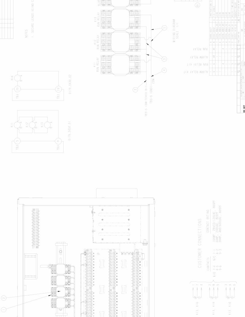

225
AM
PFI
RE
PU
MP
CB
125
AM
PLI
FES
AFE
TYC
B
DIE
CTI
ON
OF
AIR
FLO
W-R
AD
IATO
R


125
AM
P


Warranty Statement
English Effective Date: 01-October-2009
Global Commercial Warranty Statement
Commercial Generating Set
A028U870 (Issue 2)
generator warranty

This page is intentionally left blank.
Effective Date: 01-October-2009 Page 1 of 2 A028U870
Limited Warranty
Commercial Generating Set This limited warranty applies to all Cummins Power Generation branded commercial generating sets and associated accessories (hereinafter referred to as "Product").
This warranty covers any failures of the Product, under normal use and service, which result from a defect in material or factory workmanship.
Warranty Period: The warranty start date† is the date of initial start up, first rental, demonstration or 18 months after factory ship date, whichever is sooner. See table for details.
Continuous Power (COP) is defined as being the maximum power which the generating set is capable of delivering continuously whilst supplying a constant electrical load when operated for an unlimited number of hours per year. No overload capability is available for this rating.
Prime Power (PRP) is defined as being the maximum power which a generating set is capable of delivering continuously whilst supplying a variable electrical load when operated for an unlimited number of hours per year. The permissible average power output over 24 hours of operation shall not exceed 70% of the PRP. For applications requiring permissible average output higher than stated, a COP rating should be used.
Limited-Time Running Power (LTP) is defined as the maximum power available, under the agreed operating conditions, for which the generating set is capable of delivering for up to 500 hours of operation per year.
Emergency Standby Power (ESP) is defined as the maximum power available during a variable electrical power sequence, under the stated operating conditions, for which a generating set is capable of delivering in the event of a utility power outage or under test conditions for up to 200 hours of operation per year. The permissible average power output over 24 hours of operation shall not exceed 70% of the ESP.
Base Warranty Coverage Duration (Whichever occurs first)
Rating Months Max. Hours COP 12 Unlimited PRP 12 Unlimited LTP 12 500 hrs ESP 24 400 hrs
† Warranty start date for designated rental and oil and gas model Products is determined to be date of receipt of Product by the end customer.
Cummins Power GenerationResponsibilities: In the event of a failure of the Product during the warranty period due to defects in material or workmanship, Cummins Power Generation will only be responsible for the following costs:
All parts and labor required to repair the Product.
Reasonable travel expenses to and from the Product site location.
Maintenance items that are contaminated or damaged by a warrantable failure.
Owner Responsibilities: The owner will be responsible for the following:
Notifying Cummins Power Generationdistributor or dealer within 30 days of the discovery of failure.
Installing, operating, commissioning and maintaining the Product in accordance with Cummins Power Generation ’s published policies and guidelines.
Providing evidence for date of commissioning.
Providing sufficient access to and reasonable ability to remove the Product from the installation in the event of a warrantable failure.
In addition, the owner will be responsible for:
Incremental costs and expenses associated with Product removal and reinstallation resulting from non-standard installations.
Costs associated with rental of generating sets used to replace the Product being repaired.

Effective Date: 01-October-2009 Page 2 of 2 A028U870
Costs associated with labor overtime and premium shipping requested by the owner.
All downtime expenses, fines, all applicable taxes, and other losses resulting from a warrantable failure.
Limitations:This limited warranty does not cover Product failures resulting from:
Inappropriate use relative to designated power rating.
Inappropriate use relative to application guidelines.
Normal wear and tear. Improper and/or unauthorized installation. Negligence, accidents or misuse. Lack of maintenance or unauthorized repair. Noncompliance with any Cummins Power
Generation published guideline or policy. Use of improper or contaminated fuels,
coolants or lubricants. Improper storage before and after
commissioning. Owner’s delay in making Product available
after notification of potential Product problem. Use of steel enclosures within 60 miles of the
coast of salt water when aluminum or an alternate non-corrosive material enclosure option is available.
Replacement parts and accessories not authorized by Cummins Power Generation .
Use of Battle Short Mode. Owner or operator abuse or neglect such as:
operation without adequate coolant or lubricants; overfueling; overspeeding; lack of maintenance to lubricating, cooling or air intake systems; late servicing and maintenance; improper storage, starting, warm-up, run-in or shutdown practices, or for progressive damage resulting from a defective shutdown or warning device.
Damage to parts, fixtures, housings, attachments and accessory items that are not part of the generating set.
This limited warranty does not cover costs resulting from:
Difficulty in gaining access to the Product. Repair of cosmetic damage to enclosures.
Please contact your local Cummins Power Generation Distributor for clarification concerning these limitations.
CUMMINS POWER GENERATION RIGHT TO FAILED COMPONENTS:
Failed components claimed under warranty remain the property of Cummins Power Generation .Cummins Power Generation has the right to reclaim any failed component that has been replaced under warranty.
Extended Warranty: Cummins Power Generation offers several levels of Extended Warranty Coverage. Please contact your local Cummins Power Generation Distributor for details.
www.cumminspower.com
THE WARRANTIES SET FORTH HEREIN ARE THE SOLE WARRANTIES MADE BY CUMMINS POWER GENERATION IN REGARD TO THE PRODUCT. CUMMINS POWER GENERATIONMAKES NO OTHER WARRANTIES, EXPRESS OR IMPLIED, OR OF MERCHANTABILITY OR FITNESS FOR A PARTICULAR PURPOSE.
IN NO EVENT IS CUMMINS POWER GENERATION LIABLE FOR INCIDENTAL OR CONSEQUENTIAL DAMAGES.
This limited warranty shall be enforced to the maximum extent permitted by applicable law. This limited warranty gives the owner specific rights that may vary from state to state or from jurisdiction to jurisdiction.
Product Model Number:
Product Serial Number:
Date in Service:

Notes:
________________________________________________________________
________________________________________________________________

Warranty Statement
English Effective Date: 01-October-2009
Global Power Electronics Warranty Statement
Paralleling SystemTransfer Switch
A029Y876 (Issue 1)
ATS WARRANTY

This page is intentionally left blank.

Effective Date: 01-October-2009 Page 1 of 2 A029Y876
Limited Warranty
Transfer Switch and Paralleling SystemsThis limited warranty applies to all Cummins Power Generation branded Transfer Switches, Paralleling Systems and associated accessories (hereinafter referred to as "Product").
This warranty covers any failures of the Product, under normal use and service, which result from a defect in material or factory workmanship.
Warranty Period: The warranty start date is the date of commissioning†,demonstration or 18 months after factory ship date, whichever is sooner. † Date of commissioning not to exceed date of Generator Set initial start-up.
Transfer Switch Coverage Duration: The warranty coverage duration for Transfer Switches is defined in the table below for the different product families:
Product Family Duration
GTEC, LT, LC, RSS, RST, OTEC
1 Year: Parts, Labor & Travel
PLTO, PLTH, PLTS, PLTE
2 Years: Parts, Labor & Travel
Other Power Transfer Devices†† 2 Years: Parts, Labor & Travel
OT, OTPC, BTPC, OHPC, CHPC
Years 0-2: Parts, Labor &Travel Years 3-5: Parts Only Years 6-10: Main Contacts Only
†† Devices manufactured by Cummins Power Generation that allow power transfer between two power sources.
Paralleling Systems Coverage Duration: The warranty coverage duration for Paralleling Systems is for a period of 2 Years from the warranty start date.
Cummins Power GenerationResponsibilities: In the event of a failure of the Product during the warranty period due to defects in material or workmanship, Cummins Power Generation will only be responsible for the following costs:
All parts and labor required to repair the Product†††.
Reasonable travel expenses to and from the Product site location†††.††† Years 0-2 only for OT, OTPC, BTPC, OHPC & CHPC family of Transfer Switches.
Owner Responsibilities: The owner will be responsible for the following:
Notifying Cummins Power Generationdistributor or dealer within 30 days of the discovery of failure.
Installing, operating, commissioning and maintaining the Product in accordance with Cummins Power Generation ’s published policies and guidelines.
Providing evidence for date of commissioning.
Providing sufficient access to and reasonable ability to remove the Product from the installation in the event of a warrantable failure.
In addition, the owner will be responsible for:
Incremental costs and expenses associated with Product removal and reinstallation resulting from non-standard installations.
Costs associated with rental of power generating equipment used to replace the Product being repaired.
Costs associated with labor overtime and premium shipping requested by the owner.
All downtime expenses, fines, all applicable taxes, and other losses resulting from a warrantable failure.

Effective Date: 01-October-2009 Page 2 of 2 A029Y876
Limitations:This limited warranty does not cover Product failures resulting from:
Inappropriate use relative to designated power rating.
Inappropriate use relative to application guidelines.
Non-conformance to applicable industry standards for installation
Normal wear and tear. Improper and/or unauthorized installation. Negligence, accidents or misuse. Lack of maintenance or unauthorized repair. Noncompliance with any Cummins Power
Generation published guideline or policy. Improper storage before and after
commissioning. Owner’s delay in making Product available
after notification of potential Product problem. Use of steel enclosures within 60 miles of the
coast of salt water when aluminum or an alternate non-corrosive material enclosure option is available.
Replacement parts and accessories not authorized by Cummins Power Generation .
Owner or operator abuse or neglect such as: late servicing and maintenance and improper storage.
Damage to parts, fixtures, housings, attachments and accessory items that are not part of the transfer switch or paralleling system.
This limited warranty does not cover costs resulting from:
Difficulty in gaining access to the Product. Repair of cosmetic damage to enclosures.
Please contact your local Cummins Power Generation Distributor for clarification concerning these limitations.
CUMMINS POWER GENERATION RIGHT TO FAILED COMPONENTS: Failed components claimed under warranty remain the property of Cummins Power Generation .Cummins Power Generation has the right to reclaim any failed component that has been replaced under warranty.
Extended Warranty: Cummins Power Generation offers several levels of Extended Warranty Coverage. Please contact your local Cummins Power Generation Distributor for details.
www.cumminspower.com
THE WARRANTIES SET FORTH HEREIN ARE THE SOLE WARRANTIES MADE BY CUMMINS POWER GENERATION IN REGARD TO THE PRODUCT. CUMMINS POWER GENERATIONMAKES NO OTHER WARRANTIES, EXPRESS OR IMPLIED, OR OF MERCHANTABILITY OR FITNESS FOR A PARTICULAR PURPOSE.
IN NO EVENT IS CUMMINS POWER GENERATION LIABLE FOR INCIDENTAL OR CONSEQUENTIAL DAMAGES.
This limited warranty shall be enforced to the maximum extent permitted by applicable law. This limited warranty gives the owner specific rights that may vary from state to state or from jurisdiction to jurisdiction.
Product Model Number:
Product Serial Number:
Date in Service:

Notes:
________________________________________________________________
________________________________________________________________


2012 Cummins Power Generation Inc. All rights reserved. Cummins Power Generation and Cummins are registered trademarks of Cummins Inc. PowerCommand and “Our energy working for you.” are trademarks of Cummins Power Generation. Other company, product, or service names may be trademarks or service marks of others. Specifications are subject to change without notice. S-1270ad (5/12)
OTPC transfer switch open and closed transition
Description OTPC transfer switches are designed for operation and switching of electrical loads between primary power and standby generator sets. They are suitable for use in emergency, legally required and optional standby applications. The switch monitors both power sources, signals generator set startup, automatically transfers power, and returns the load to the primary power source when the utility returns and stabilizes.
OTPC transfer switches are available with closed transition transfer. By briefly connecting the two sources (for 100 msec or less), the transfer from the alternate source back to the normal source occurs without interruption in the power supply to loads.
Features PowerCommand® control - A fully featured microprocessor-based control with digital display. Controls allow operator to enter settings and make adjustments to software-enabled features easily and accurately. Accommodates up to eight event schedules.
Programmed transition – Open transition timing can be adjusted to completely disconnect the load from both sources for a programmed time period, as recommended by NEMA MG-1 for transfer of inductive loads.
Advanced transfer switch mechanism – Unique bi-directional linear actuator provides smooth, continuous transfer switch action during automatic operation.
Robust control system design - Optically isolated logic inputs and isolation transformers for AC power inputs provide high-voltage surge protection.
Main contacts - Heavy-duty silver alloy contacts with multi-leaf arc chutes are rated for 100% load interruption. They require no routine contact maintenance and provide 100% continuous current ratings.
Communications capability - The transfer switch is capable of communicating with other transfer switches, SCADA and remote monitoring systems, or Cummins Power Generation generators utilizing LonWorks®® protocol.
Easy service/access - Single-plug harness connection and compatible terminal markings simplify servicing. Access space is ample. Door-mounted controls are field-programmable; no tool is required.
Complete product line - Cummins Power Generation offers a wide range of equipment, accessories and services to suit virtually any backup power application.
Warranty and service - Products are backed by a comprehensive warranty and a worldwide network of distributors with factory-trained service technicians.
All switches are UL 1008 Listed with UL Type Rated cabinets and UL Listed CU-AL terminals.
All switches are certified to CSA 282 Emergency Electrical Power Supply for Buildings, up to 600 VAC.
NEC
Suitable for use in emergency, legally required and standby applications per NEC 700, 701 and 702.
All switches comply with NFPA 70, 99 and 110 (Level 1).
All switches comply with NEMA ICS 10.
All switches comply with IEEE 446 Recommended Practice for Emergency and Standby Power Systems.
This transfer switch is designed and manufactured in facilities certified to ISO9001.
40 - 4000 Amp
800 AMP4 POLE480V3 PHASELEVEL 1NEMA 1

Our energy working for you.™
www.cumminspower.com 2012 Cummins Power Generation Inc. All rights reserved. Cummins Power Generation and Cummins are registered trademarks of Cummins
Inc. PowerCommand and “Our energy working for you.” are trademarks of Cummins Power Generation. Other company, product, or service names may be trademarks or service marks of others. Specifications are subject to change without notice. S-1270ad (5/12)
Transfer switch mechanism
Transfer switch mechanism is electrically operated and mechanically held in the Source 1 and Source 2 positions. The transfer switch incorporates electrical and mechanical interlocks to prevent inadvertent interconnection of the sources.
Independent break-before-make action is used for both 3-pole and 4-pole/ switched neutral switches. This design allows use of sync check operation when required, or control of the operating speed of the transfer switch for proper transfer of motor and rectifier-based loads (programmed transition feature).
True 4-pole switching allows for proper ground (earth) fault sensing and consistent, reliable operation for the life of the transfer switch. The neutral poles of the transfer switch have the same ratings as the phase poles and are operated by a common crossbar mechanism, eliminating the possibility of incorrect neutral operation at any point in the operating cycle, or due to failure of a neutral operator.
High pressure silver alloy contacts resist burning and pitting. Separate arcing surfaces further protect the main contacts. Contact wear is reduced by multiple leaf arc chutes that cool and quench the arcs. Barriers separate the phases to prevent interphase flashover. A transparent protective cover allows visual inspection while inhibiting inadvertent contact with energized components.
Switch mechanism, including contact assemblies, is third party certified to verify suitability for applications requiring high endurance switching capability for the life of the transfer switch. Withstand and closing ratings are validated using the same set of contacts, further demonstrating the robust nature of the design.
Specifications
Voltage rating 600 VAC, 50 or 60 Hz.
Arc interruption Multiple leaf arc chutes provide dependable arc interruption.
Neutral bar A full current-rated neutral bar with lugs is standard on enclosed 3-pole transfer switches.
Auxiliary contacts
Two isolated contacts (one for each source) indicating switch position are provided for customer use. Contacts are normally open, and close to indicate connection to the source. Wired to terminal block for easy access. Rated at 10 amps continuous and 250 VAC maximum. UL recognized, and CSA-certified.
Operating temperature -40 F (-40 C) to 140 F (60 C)
Storage temperature -40 F (-40 C) to 140 F (60 C)
Humidity Up to 95% relative, non-condensing
Altitude Up to 10,000 ft (3,000 m) without derating
Surge withstand ratings Voltage surge performance and testing in compliance with the requirements of IEEE C62.41 (Category B3) and IEEE C62.45.
Total transfer time (source-to-source)
Will not exceed 6 cycles at 60 Hz with normal voltage applied to the actuator and without programmed transition enabled.
Manual operation handles
Transfer switches rated through 1000 amps are equipped with permanently attached operating handles and quick-break, quick-make contact mechanisms suitable for manual operation. Transfer switches over 1000 amps are equipped with manual operators. All switches must be de-energized before manual operation is attempted.
Transition modes Open transition/programmed: Controls the time required for the device to switch from source to source, so that the load-generated voltages decay to a safe level before connecting to an energized source. Recommended by NEMA MG-1 to prevent nuisance-tripping breakers and load damage. Adjustable 0-60 seconds, default 0 seconds. Programmed transition is standard on 150-1200 amp switches, and optional on 1600-4000 amps. Open transition/in-phase: Initiates open transition transfer when in-phase monitor senses both sources are in phase. Operates in a break-before-make sequence. Includes ability to enable programmed transition as a back-up. If sources are not in phase within 120 seconds, switches from 40-1200 amps will transfer using programmed transition (not available on open transition switches over 1200 amps). Closed transition: Used in applications where loads are sensitive to the momentary power interruption that occurs when performing open transition between sources. Closed transition is accomplished by briefly (<100 msec) paralleling two good sources to eliminate the momentary break in the power supply. Closed transition is only available as an option on OTPC models from 1000-4000 amps. Genset-to-genset: Either genset can be designated as the lead genset. If the lead genset goes down or is taken offline, the transfer switch starts the second genset and transfers the load. The control can be programmed to alternate between the two gensets at a set interval up to 336 hours (2 weeks).

Our energy working for you.™
www.cumminspower.com 2012 Cummins Power Generation Inc. All rights reserved. Cummins Power Generation and Cummins are registered trademarks of Cummins
Inc. PowerCommand and “Our energy working for you.” are trademarks of Cummins Power Generation. Other company, product, or service names may be trademarks or service marks of others. Specifications are subject to change without notice. S-1270ad (5/12)
PowerCommand control PowerCommand controls are microprocessor based and developed specifically for automatic transfer switch operation. The control includes all of the features and options required for most applications. LED lamps indicate source availability, source connected, exercise mode and test mode. Flash memory stores the control settings. Contents of the memory are not lost even if power to the controller is lost. On-board battery maintains the real-time clock setting and the engine start time delay. Choice of two control packages allows selection of the most suitable control for the application.
Control functions
Level 1 control (C023) LLevel 2 control ((C024) Open transition (in-phase) Open transition (programmed) Utility-to-genset applications Software adjustable time delays:
Engine start: 0 to 120 sec Transfer normal to emergency: 0 to 120 sec Re-transfer emergency to normal: 0 to 30 min Engine stop: 0 to 30 min Programmed transition: 0 to 60 sec
Undervoltage sensing: 3-phase normal, 1-phase emergency Accuracy: =/- 2% Pickup: 85% to 100% of nominal voltage Dropout: 75% to 98% of pickup setting Dropout time delay: 0-4 sec
Overvoltage sensing: 3-phase normal, 1-phase emergency Accuracy: =/- 2% Pickup: 95% to 99% of dropout setting Dropout: 105% to 135% of nominal voltage Dropout time delay: 0 to 120 sec
Over/under frequency sensing: Accuracy: ±0.05 Hz Pickup: ±5% to ±20% of nominal frequency Dropout: 1-5% beyond pickup Dropout time delay: 0.1 to 15.0 sec
Programmable genset exerciser: One event/schedule with or w/o load Basic indicator panel:
Source available/connected LED indicators Test/exercise/override buttons Digital display – optional (M018) Analog bar graph meter display – optional (D009)
Date/time-stamped event recording: 50 events Load sequencing: Optional with network communications module M031. Provides control for eight steps of load with an adjustable time delay for each step on transfer, re-transfer or both.
Open transition (in-phase) Open transition (programmed) Closed transition (includes fail-to-disconnect timer to prevent extended paralleling with the utility) Utility-to-genset applications Utility-to-utility applications Genset-to-genset applications Software adjustable time delays:
Engine start: 0 to 120 sec Transfer normal to emergency: 0 to 120 sec Re-transfer emergency to normal: 0 to 30 min Engine stop: 0 to 30 min Programmed transition: 0 to 60 sec
Undervoltage sensing: 3-phase normal, 3-phase emergency Accuracy: +/- 2% Pickup: 85% to 100% of nominal voltage Dropout: 75% to 98% of pickup setting Dropout time delay: 0-4 sec
Overvoltage sensing: 3-phase normal, 3-phase emergency Accuracy: ±2% Pickup: 95% to 99% of dropout setting Dropout: 105% to 135% of nominal voltage Dropout time delay: 0 to 120 sec
Over/under frequency sensing: Accuracy: =/- 0.05 Hz Pickup: ±5% to ±20% of nominal frequency Dropout: 1-5% beyond pickup Dropout time delay: 0.1 to 15.0 sec
Voltage imbalance sensing: Dropout: 2% to 10% Pickup: 90% of dropout Time delay: 2.0 to 20.0 sec
Phase rotation sensing: Time delay: 100 msec
Loss of single phase detection: Time delay: 100 msec
Programmable genset exerciser: Eight events/schedules with or w/o load Basic indicator panel:
Source available/connected LED indicators Test/exercise/override buttons Digital display – standard Analog bar graph meter display – optional (D009)
Date/time-stamped event recording: 50 events Load sequencing: Optional with network communications module M031. Provides control for eight steps of load with an adjustable time delay for each step on transfer, re-transfer, or both. Genset-to-genset: Same functions as above, for lead and secondary generators. Utility-to-utility: Same functions as above, for preferred and alternate source.

2012 Cummins Power Generation Inc. All rights reserved. Cummins Power Generation and Cummins are registered trademarks of Cummins Inc. PowerCommand and “Our energy working for you.” are trademarks of Cummins Power Generation. Other company, product, or service names may be trademarks or service marks of others. Specifications are subject to change without notice. S-1270ad (5/12)
Time-delay functions
Engine start: Prevents nuisance genset starts due to momentary power system variation or loss. Not included in utility-to-utility systems. Transfer normal to emergency: Allows genset to stabilize before application of load. Prevents power interruption if normal source variation or loss is momentary. Allows staggered transfer of loads in multiple transfer switch systems. For genset-to-genset applications, delays transfer of load from lead to secondary generator. Re-transfer emergency to normal: Allows the utility to stabilize before re-transfer of load. Prevents needless power interruption if return of normal source is momentary. Allows staggered transfer of loads in multiple transfer switch systems. For genset-to-genset applications, delays re-transfer of load from secondary back to lead generator. Engine stop: Maintains availability of the genset for immediate reconnection if the normal source fails shortly after retransfer. Allows gradual genset cool down by running unloaded. Not included in utility-to-utility systems. Elevator pre-transfer signal: Requires optional relay signal module (M023). Signals elevator system that transfer is pending and delays transfer for pre-set interval of 0-60 seconds to prevent a power interruption during elevator operation.
User interfaces
Basic interface panel
LED indicators provide at-a-glance source and transfer switch status for quick summary of system conditions. Test and override buttons allow delays to be bypassed for rapid system checkout.
Digital display (M018)
The digital display provides a convenient method for monitoring load power conditions, adjusting transfer switch parameters, monitoring PowerCommand network status or reviewing transfer switch events. Password protection limits access to adjustments to authorized personnel. The digital display is optional with the PowerCommand Level 1 control and comes standard with the Level 2 control.
User interface options
Front panel security key (M017)
Locks front panel to prohibit access to digital control settings. Prevents unauthorized activation of transfer or test functions.
Bar graph meter display (D009)
An LED bar graph display provides an easy-to-read indicator of the level of power being supplied to the load. Information displayed includes: 3-phase voltage and current, frequency, power factor, and kilowatts. Green, amber, and red LEDs provide at-a-glance indication of system acceptability. Available as an option with the Level 2 PowerCommand microprocessor control.
Control options
Relay signal module (M023)
Provides relay output contacts for sending information to the building monitoring and control system. Relay outputs include: Source 1 connected/available, Source 2 connected/available, not in auto, test/exercise active, failed to disconnect, failed to synchronize, failed to transfer/re-transfer, and elevator control pre-transfer signal.
Loadshed (M007)
Removes the load from the emergency power source by driving the transfer switch to the neutral position when signaled remotely. Transfers load back to the emergency source when the signal contacts open. Immediately re-transfers back to the primary source when available. Available for utility-to-genset applications only.
PowerCommand network interface (M031)
Provides connection to the PowerCommand network. LonWorks compatible for integration with building monitoring and control system.
Load power and load current monitoring (M022)
Measures load phase and neutral current, power factor, real power (kW) and apparent power (kVA). Warns of excessive neutral current resulting from unbalanced or nonlinear loads. Minimum current level detection is 3%.

Our energy working for you.™
www.cumminspower.com 2012 Cummins Power Generation Inc. All rights reserved. Cummins Power Generation and Cummins are registered trademarks of Cummins
Inc. PowerCommand and “Our energy working for you.” are trademarks of Cummins Power Generation. Other company, product, or service names may be trademarks or service marks of others. Specifications are subject to change without notice. S-1270ad (5/12)
UL withstand and closing ratings OTPC transfer switches must be protected by circuit breakers or fuses. Referenced drawings include detailed listings of specific breakers or fuse types that must be used with the respective transfer switches. Consult with your distributor/dealer to obtain the necessary drawings. Withstand and closing ratings (WCR) are stated in symmetrical RMS amperes.
MCCB protection Special circuit breaker protection
Transfer switch ampere
WCR @ volts max with specific manufacturers MCCBs
Max MCCB rating
Drawing reference
With specific current limiting breakers (CLB)
Max CLB rating Drawing reference
40, 70, 125 3-pole 14,000 at 480
225 A 0098-6885 200,000 at 480
225 A 0098-6918 14,000 at 600 100,000 at 600
40, 70, 125 4-pole 30,000 at 480
400 A 0098-6886 200,000 at 480
400 A 0098-6919 30,000 at 600 100,000 at 600
150, 225, 260 30,000 at 480
400 A 0098-6886 200,000 at 480
400 A 0098-6919 30,000 at 600 100,000 at 600
300, 400, 600 65,000 at 480
1200 A 0098-6887 200,000 at 480
1200 A 0098-6920 65,000 at 600 100,000 at 600
800, 1000 open 65,000 at 480
1400 A 0098-6888 150,000 at 480
1400 A 0098-6921 50,000 at 600 100,000 at 600
1000, 1200 closed 85,000 at 480
1600 A 0098-7312 85,000 at 480
1600 A 0098-7312 65,000 at 600* 65,000 at 600
1200 open 85,000 at 480
1600 A A030U183 200,000 at 480
1600 A A030U185 65,000 at 600 200,000 at 600
1600, 2000 100,000 at 480
4000 A 0098-7311 100,000 at 480
4000 A 0098-7311 85,000 at 600* 85,000 at 600
3000 100,000 at 480
4000 A 0098-7313 100,000 at 480
4000 A 0098-7313 85,000 at 600* 85,000 at 600
4000 100,000 at 480
5000 A 0098-8576 100,000 at 480 5000 A 0098-8576 85,000 at 600*
Fuse protection
Transfer switch ampere
WCR @ volts max. with current limiting fuses Max fuse, size and type Drawing reference
40, 70, 125 3- and 4-pole
200,000 at 480 200 A Class, J, RK1, RK5, T 0098-6885
200,000 at 600
150, 225, 260 200,000 at 480 600 A Class, J, RK1, RK5
1200 A Class L or T 0098-6886 200,000 at 600
300, 400, 600 200,000 at 480 600 A Class, RK1 or RK5
1200 A Class L or T 0098-6887
200,000 at 600
800, 1000 open 200,000 at 480 600 A Class, J, RK1 or RK5
1200 A Class T 2000 A Class L
0098-6888 200,000 at 600
1000, 1200 closed 200,000 at 480
3000 A Class L 0098-7312 150,000 at 600*
1200 open 200,000 at 480
3000 A Class L A030U183 150,000 at 600*
1600, 2000 200,000 at 480
2500 A Class L 0098-7311 150,000 at 600*
3000 200,000 at 480
4000 A Class L 0098-7313 150,000 at 600*
4000 200,000 at 480
6000 A Class L 0098-8576 150,000 at 600*
* CSA only

Our energy working for you.™
www.cumminspower.com 2012 Cummins Power Generation Inc. All rights reserved. Cummins Power Generation and Cummins are registered trademarks of Cummins
Inc. PowerCommand and “Our energy working for you.” are trademarks of Cummins Power Generation. Other company, product, or service names may be trademarks or service marks of others. Specifications are subject to change without notice. S-1270ad (5/12)
3-cycle ratings
Transfer switch ampere
WCR @ volts max 3-cycle rating Max MCCB rating Drawing reference
1000, 1200 closed 50,000 at 480
1600 A 0098-7312 42,000 at 600*
1200 open 50,000 at 480
1600 A A030U183 42,000 at 600*
1600, 2000 100,000 at 480
4000 A 0098-7311 85,000 at 600*
3000 100,000 at 480
4000 A 0098-7313 85,000 at 600*
4000 100,000 at 480
5000 A 0098-8576 85,000 at 600*
* CSA only
Transfer switch lug capacities All lugs accept copper or aluminum wire unless indicated otherwise.
Amp rating Cables per phase Size
40, 70, 125 3-pole 1 #12 AWG-2/0 40 4-pole 1 #14 AWG-2/0 70, 125 4-pole 1 #6 AWG - 300 MCM 150, 225 1 #6 AWG - 300 MCM 260 1 #6 AWG - 400 MCM
300, 400 1 3/0 - 600 MCM 1 or 2 3/0 - 250 MCM
600 2 250 - 500 MCM 800, 1000 open 4 250 - 500 MCM 1000, 1200 closed 4 #2 AWG to 600 MCM 1200 open 4 #2AWG to 750 MCM 1600, 2000 8 #2 AWG to 600 MCM (lugs optional) 3000 8 #2 AWG to 750 MCM (lugs optional) 4000 12 1/0 AWG to 750 MCM (lugs optional)

2012 Cummins Power Generation Inc. All rights reserved. Cummins Power Generation and Cummins are registered trademarks of Cummins Inc. PowerCommand and “Our energy working for you.” are trademarks of Cummins Power Generation. Other company, product, or service names may be trademarks or service marks of others. Specifications are subject to change without notice. S-1270ad (5/12)
Enclosures The transfer switch and control are mounted in a key-locking enclosure. Switches from 40-1000 amps are wall-mounted. Switches from 1200-4000 amps are floor-mounted. Wire bend space complies with 2009 NEC.
Dimensions - transfer switch in UL type 1 enclosure
Amp rating Height Width Depth
Weight Outline drawing Door closed Door open in mm in mm in mm in mm lb kg 40, 70, 125 3-pole 27.0 686 20.5 521 12.0 305 31.5 800 82 37 0310-0544 40, 70, 125 4-pole 35.5 902 26.0 660 16.0 406 41.0 1042 165 75 0500-4896 150, 225 35.5 902 26.0 660 16.0 406 41.0 1042 165 75 0310-0414 260 43.5 1105 28.5 724 16.0 406 43.0 1093 170 77 0310-0540 300, 400, 600 54.0 1372 25.5 648 18.0 457 42.0 1067 225 102 0310-1307 800, 1000 open 68.0 1727 30.0 762 20.6 524 48.5 1232 360 163 0310-0417 1000, 1200 closed 76.3 1937 36.0 915 22.7 577 54.0 1372 450 204 0310-0482 1200 open 90.0 2290 39.0 991 27.5 699 64.7 1644 730 331 A030L605 1600, 2000* 90.0 2290 36.0. 915 48.0 1219 84.0 2134 1100 499 0310-0483 3000* 90.0 2290 36.0 915 48.0 1219 84.0 2134 1250 567 0310-0484 4000* 90.0 2290 46.5 1180 60.0 1520 106 2700 1850 839 0500-4485
Dimensions - transfer switch in UL type 3R, 4 or 12 enclosure
Amp rating Height Width Depth
Weight Cabinet type
Outline drawing Door closed Door open
in mm in mm in mm in mm lb kg
40, 70, 125 3-pole 34.0 864 26.5 673 12.5 318 36.5 927 125 57 3R, 12 0310-0453 4 0310-0445
40, 70, 125 4-pole 42.5 1080 30.5 775 16.0 406 44.0 1118 190 86 3R, 12 0500-4896 4 0500-4896
150, 225 42.5 1080 30.5 775 16.0 406 44.0 1118 215 97 3R, 12 0310-0454 4 0310-0446
260 46.0 1168 32.0 813 16.0 406 46.0 1168 255 102 3R, 12 0310-0455 4 0310-0447
300, 400, 600 59.0 1499 27.5 699 18.5 419 41.5 1054 290 132 3R, 12 0310-1315 4 0310-1316
800, 1000 open 73.5 1867 32.5 826 20.8 529 49.5 1257 410 186 3R, 12 0310-0457 4 0310-0449
1000, 1200 closed 76.3 1937 36.0 915 22.7 577 54.0 1372 450 204 3R, 12, 4 0310-0482
1200 open 90.0 2290 39.0 991 27.5 699 64.7 1644 730 331 3R, 12 A030L605 4 A041N372
1600, 2000* 90.0 2290 38.0 826 50.9 1293 80.0 2032 1100 499 3R, 12, 4 0310-0744 3000* 90.0 2290 38.0 965 51.0 1295 84.5 2146 1250 567 3R 0310-0745 4000* 90.0 2290 49.0 1244 60.0 1524 105 2654 1850 839 3R 0500-4486
Dimensions - transfer switch in UL type 4X stainless steel enclosure
Amp rating Height Width Depth
Weight Cabinet type
Outline drawing Door closed Door open
in mm in mm in mm in mm lb kg 40, 70, 125 3-pole 46.0 1168 32.0 813 16.0 406 46.0 1168 255 102 4X 0500-4184 40, 70, 125 4-pole 46.0 1168 32.0 813 16.0 406 46.0 1168 255 102 4X 0500-4896 150, 225 46.0 1168 32.0 813 16.0 406 46.0 1168 255 102 4X 0500-4184 260 46.0 1168 32.0 813 16.0 406 46.0 1168 255 102 4X 0500-4184 300, 400, 600 73.5 1867 32.5 826 19.5 495 49.5 1257 410 186 4X 0500-4185 800, 1000 open 73.5 1867 32.5 826 19.5 495 49.5 1257 410 186 4X 0500-4185 1000, 1200 closed 70.0 1778 40.0 1016 19.8 502 59.0 1499 450 204 4X 0310-0482 1200 open 90.0 2290 39.0 991 27.5 699 64.7 1644 730 331 4X A041N372 1600, 2000 90.0 2290 35.5 826 50.9 1293 80.0 2032 1100 499 4X 0310-0744
* Rear and side access is required for installation. Dimensions shown are for 4-pole. For information on 3-pole switches, call factory.

Our energy working for you.™
www.cumminspower.com 2012 Cummins Power Generation Inc. All rights reserved. Cummins Power Generation and Cummins are registered trademarks of Cummins
Inc. PowerCommand and “Our energy working for you.” are trademarks of Cummins Power Generation. Other company, product, or service names may be trademarks or service marks of others. Specifications are subject to change without notice. S-1270ad (5/12)
Submittal detail Amperage ratings
40 70 125 150 225 260 300 400 600 800 1000 1200 1600 2000 3000 4000
Voltage ratings R020 120* R038 190 R021 208 R022 220 R023 240 R024 380 R025 416 R035 440 R026 480 R027 600
* Single phase connection (not available on 1200-4000 amps) Pole configuration
A028 Poles - 3 (solid neutral) A029 Poles - 4 (switched neutral)
Frequency A044 60 Hertz A045 50 Hertz
Transfer mode A077 Open transition/in-phase A078 Open transition/programmed A079 Closed transition (available 1000-4000 amps, for closed
transition below 1000 amps, see CHPC spec sheet S-1437) Applicationn
A035 Utility to genset A036 Utility to utility A037 Genset to genset
System options A041 Single Phase, 2-wire or 3-wire (not available 1200-4000 amps) A042 Three Phase, 3-wire or 4-wire
Enclosure B001 Type 1: Indoor use, provides some protection against dirt
(similar to IEC type IP30) B002 Type 3R:Intended for outdoor use, provides some protection
from dirt, rain and snow (similar to IEC type IP34) B003 Type 4: Indoor or outdoor use, provides some protection from
wind-blown dust and water spray (similar to IEC type IP65) B004 Open Construction: No enclosure - includes automatic transfer
switch and controls (call factory for dimensions) B010 Type 12: Indoor use, some protection from dust (similar to IEC
type IP61) B025 Type 4X: Stainless steel, indoor or outdoor use, provides some
protection from corrosion (similar to IEC Type IP65)
Standards A046 UL 1008/CSA certification A064 NFPA 20 compliant (not available on 1200-4000 amp switches) A080 Seismic certification
Controls C023 PowerCommand control - Level 1 C024 PowerCommand control - Level 2
Control options M017 Security key - front panel M018 Digital display M022 Load monitoring (min current level 3%) M023 Relay signal module. Includes pre-transfer module for
elevator control M031 LonWorks network communications module (FTT-10)
Meter D009 Analog bar graph meter
Battery chargers K001 2 amps, 12/24 volts KB59 15 amps, 12 volts KB60 12 amps, 24 volts
Protective relays (closed transition) M045 Paralleling timer and lock-out relays, ANSI/IEEE 62PL and 86 M046 Paralleling timer, lock-out and reverse power relays, single
phase, ANSI/IEEE 62PL, 86 and 32R M047 Paralleling timer, lock-out and reverse power relays, three
phase, ANSI/IEEE 62PL, 86 and 32R Auxiliary relays - Relays are UL listed and factory installed. All relays provide two normally closed isolated and two normally open contacts rated 10 amps at 600 VAC. Relay terminals accept from one 18 gauge to two 12 gauge wires per terminal.
L101 24 VDC coil - installed, not wired (for customer use). L102 24 VDC coil - emergency position - relay energized when
switch is in Source 2 (emergency) position. L103 24 VDC coil - normal position - relay energized when switch is
in Source 1 (normal) position L201 12 VDC coil - installed, not wired L202 12 VDC coil - emergency position - relay energized when
switch is in Source 2 (emergency) position L203 12 VDC coil - normal position - relay energized when switch is
in Source 1 (normal) position Miscellaneous options
M003 Terminal block - 30 points (not wired) N020 Terminal block – re-transfer inhibit M007 Load shed - from emergency - drives switch to neutral
position when remote signal contact closes N009 Power connect - bus stabs (150-1200 amp open construction
only) N013 Extension harness (open construction only)
Lug kits (select one) N032 Lug adapters, compression, ½ stab N045 Cable lugs, mechanical, 600 MCM, 4 per pole N066 Cable lugs, mechanical, 750 MCM, 4 per pole
Warranty G010 Years 0-2: Parts, labor and travel
Years 3-5: Parts only Years 6-10: Main contacts only
G013 Years 0-5: Parts, labor and travel Years 6-10: Main contacts only Shipping
A051 Packing - export box Accessories AC-167 Accessories specifications sheet
Cummins Power Generation
North America 1400 73rd Avenue N.E. Minneapolis, MN 55432 USA Phone 763 574 5000 Fax 763 574 5298
Brazil Rua Jati, 310 Guarulhos – Sao Paulo CEP – 07180-140 Phone 55 11 2186 4195 Fax 55 11 2186 4729
Europe, CIS, Middle East and Africa Manston Park Columbus Ave. Manston Ramsgate Kent CT 12 5BF United Kingdom Phone 44 1843 255000 Fax 44 1843 255902
Asia Pacific 10 Toh Guan Road #07-01 TT International Tradepark Singapore 608838 Phone 65 6417 2388 Fax 65 6417 2399


2012 Cummins Power Generation Inc. All rights reserved. Cummins Power Generation and Cummins are registered trademarks of Cummins Inc. PowerCommand and “Our energy working for you.” are trademarks of Cummins Power Generation. Other company, product, or service names may be trademarks or service marks of others. Specifications are subject to change without notice. S-1270ad (5/12)
OTPC transfer switch open and closed transition
Description OTPC transfer switches are designed for operation and switching of electrical loads between primary power and standby generator sets. They are suitable for use in emergency, legally required and optional standby applications. The switch monitors both power sources, signals generator set startup, automatically transfers power, and returns the load to the primary power source when the utility returns and stabilizes.
OTPC transfer switches are available with closed transition transfer. By briefly connecting the two sources (for 100 msec or less), the transfer from the alternate source back to the normal source occurs without interruption in the power supply to loads.
Features PowerCommand® control - A fully featured microprocessor-based control with digital display. Controls allow operator to enter settings and make adjustments to software-enabled features easily and accurately. Accommodates up to eight event schedules.
Programmed transition – Open transition timing can be adjusted to completely disconnect the load from both sources for a programmed time period, as recommended by NEMA MG-1 for transfer of inductive loads.
Advanced transfer switch mechanism – Unique bi-directional linear actuator provides smooth, continuous transfer switch action during automatic operation.
Robust control system design - Optically isolated logic inputs and isolation transformers for AC power inputs provide high-voltage surge protection.
Main contacts - Heavy-duty silver alloy contacts with multi-leaf arc chutes are rated for 100% load interruption. They require no routine contact maintenance and provide 100% continuous current ratings.
Communications capability - The transfer switch is capable of communicating with other transfer switches, SCADA and remote monitoring systems, or Cummins Power Generation generators utilizing LonWorks®® protocol.
Easy service/access - Single-plug harness connection and compatible terminal markings simplify servicing. Access space is ample. Door-mounted controls are field-programmable; no tool is required.
Complete product line - Cummins Power Generation offers a wide range of equipment, accessories and services to suit virtually any backup power application.
Warranty and service - Products are backed by a comprehensive warranty and a worldwide network of distributors with factory-trained service technicians.
All switches are UL 1008 Listed with UL Type Rated cabinets and UL Listed CU-AL terminals.
All switches are certified to CSA 282 Emergency Electrical Power Supply for Buildings, up to 600 VAC.
NEC
Suitable for use in emergency, legally required and standby applications per NEC 700, 701 and 702.
All switches comply with NFPA 70, 99 and 110 (Level 1).
All switches comply with NEMA ICS 10.
All switches comply with IEEE 446 Recommended Practice for Emergency and Standby Power Systems.
This transfer switch is designed and manufactured in facilities certified to ISO9001.
40 - 4000 Amp
125 AMP4 POLE480V3 PHASELEVEL 1NEMA 1

Our energy working for you.™
www.cumminspower.com 2012 Cummins Power Generation Inc. All rights reserved. Cummins Power Generation and Cummins are registered trademarks of Cummins
Inc. PowerCommand and “Our energy working for you.” are trademarks of Cummins Power Generation. Other company, product, or service names may be trademarks or service marks of others. Specifications are subject to change without notice. S-1270ad (5/12)
Transfer switch mechanism
Transfer switch mechanism is electrically operated and mechanically held in the Source 1 and Source 2 positions. The transfer switch incorporates electrical and mechanical interlocks to prevent inadvertent interconnection of the sources.
Independent break-before-make action is used for both 3-pole and 4-pole/ switched neutral switches. This design allows use of sync check operation when required, or control of the operating speed of the transfer switch for proper transfer of motor and rectifier-based loads (programmed transition feature).
True 4-pole switching allows for proper ground (earth) fault sensing and consistent, reliable operation for the life of the transfer switch. The neutral poles of the transfer switch have the same ratings as the phase poles and are operated by a common crossbar mechanism, eliminating the possibility of incorrect neutral operation at any point in the operating cycle, or due to failure of a neutral operator.
High pressure silver alloy contacts resist burning and pitting. Separate arcing surfaces further protect the main contacts. Contact wear is reduced by multiple leaf arc chutes that cool and quench the arcs. Barriers separate the phases to prevent interphase flashover. A transparent protective cover allows visual inspection while inhibiting inadvertent contact with energized components.
Switch mechanism, including contact assemblies, is third party certified to verify suitability for applications requiring high endurance switching capability for the life of the transfer switch. Withstand and closing ratings are validated using the same set of contacts, further demonstrating the robust nature of the design.
Specifications
Voltage rating 600 VAC, 50 or 60 Hz.
Arc interruption Multiple leaf arc chutes provide dependable arc interruption.
Neutral bar A full current-rated neutral bar with lugs is standard on enclosed 3-pole transfer switches.
Auxiliary contacts
Two isolated contacts (one for each source) indicating switch position are provided for customer use. Contacts are normally open, and close to indicate connection to the source. Wired to terminal block for easy access. Rated at 10 amps continuous and 250 VAC maximum. UL recognized, and CSA-certified.
Operating temperature -40 F (-40 C) to 140 F (60 C)
Storage temperature -40 F (-40 C) to 140 F (60 C)
Humidity Up to 95% relative, non-condensing
Altitude Up to 10,000 ft (3,000 m) without derating
Surge withstand ratings Voltage surge performance and testing in compliance with the requirements of IEEE C62.41 (Category B3) and IEEE C62.45.
Total transfer time (source-to-source)
Will not exceed 6 cycles at 60 Hz with normal voltage applied to the actuator and without programmed transition enabled.
Manual operation handles
Transfer switches rated through 1000 amps are equipped with permanently attached operating handles and quick-break, quick-make contact mechanisms suitable for manual operation. Transfer switches over 1000 amps are equipped with manual operators. All switches must be de-energized before manual operation is attempted.
Transition modes Open transition/programmed: Controls the time required for the device to switch from source to source, so that the load-generated voltages decay to a safe level before connecting to an energized source. Recommended by NEMA MG-1 to prevent nuisance-tripping breakers and load damage. Adjustable 0-60 seconds, default 0 seconds. Programmed transition is standard on 150-1200 amp switches, and optional on 1600-4000 amps. Open transition/in-phase: Initiates open transition transfer when in-phase monitor senses both sources are in phase. Operates in a break-before-make sequence. Includes ability to enable programmed transition as a back-up. If sources are not in phase within 120 seconds, switches from 40-1200 amps will transfer using programmed transition (not available on open transition switches over 1200 amps). Closed transition: Used in applications where loads are sensitive to the momentary power interruption that occurs when performing open transition between sources. Closed transition is accomplished by briefly (<100 msec) paralleling two good sources to eliminate the momentary break in the power supply. Closed transition is only available as an option on OTPC models from 1000-4000 amps. Genset-to-genset: Either genset can be designated as the lead genset. If the lead genset goes down or is taken offline, the transfer switch starts the second genset and transfers the load. The control can be programmed to alternate between the two gensets at a set interval up to 336 hours (2 weeks).

Our energy working for you.™
www.cumminspower.com 2012 Cummins Power Generation Inc. All rights reserved. Cummins Power Generation and Cummins are registered trademarks of Cummins
Inc. PowerCommand and “Our energy working for you.” are trademarks of Cummins Power Generation. Other company, product, or service names may be trademarks or service marks of others. Specifications are subject to change without notice. S-1270ad (5/12)
PowerCommand control PowerCommand controls are microprocessor based and developed specifically for automatic transfer switch operation. The control includes all of the features and options required for most applications. LED lamps indicate source availability, source connected, exercise mode and test mode. Flash memory stores the control settings. Contents of the memory are not lost even if power to the controller is lost. On-board battery maintains the real-time clock setting and the engine start time delay. Choice of two control packages allows selection of the most suitable control for the application.
Control functions
Level 1 control (C023) LLevel 2 control ((C024) Open transition (in-phase) Open transition (programmed) Utility-to-genset applications Software adjustable time delays:
Engine start: 0 to 120 sec Transfer normal to emergency: 0 to 120 sec Re-transfer emergency to normal: 0 to 30 min Engine stop: 0 to 30 min Programmed transition: 0 to 60 sec
Undervoltage sensing: 3-phase normal, 1-phase emergency Accuracy: =/- 2% Pickup: 85% to 100% of nominal voltage Dropout: 75% to 98% of pickup setting Dropout time delay: 0-4 sec
Overvoltage sensing: 3-phase normal, 1-phase emergency Accuracy: =/- 2% Pickup: 95% to 99% of dropout setting Dropout: 105% to 135% of nominal voltage Dropout time delay: 0 to 120 sec
Over/under frequency sensing: Accuracy: ±0.05 Hz Pickup: ±5% to ±20% of nominal frequency Dropout: 1-5% beyond pickup Dropout time delay: 0.1 to 15.0 sec
Programmable genset exerciser: One event/schedule with or w/o load Basic indicator panel:
Source available/connected LED indicators Test/exercise/override buttons Digital display – optional (M018) Analog bar graph meter display – optional (D009)
Date/time-stamped event recording: 50 events Load sequencing: Optional with network communications module M031. Provides control for eight steps of load with an adjustable time delay for each step on transfer, re-transfer or both.
Open transition (in-phase) Open transition (programmed) Closed transition (includes fail-to-disconnect timer to prevent extended paralleling with the utility) Utility-to-genset applications Utility-to-utility applications Genset-to-genset applications Software adjustable time delays:
Engine start: 0 to 120 sec Transfer normal to emergency: 0 to 120 sec Re-transfer emergency to normal: 0 to 30 min Engine stop: 0 to 30 min Programmed transition: 0 to 60 sec
Undervoltage sensing: 3-phase normal, 3-phase emergency Accuracy: +/- 2% Pickup: 85% to 100% of nominal voltage Dropout: 75% to 98% of pickup setting Dropout time delay: 0-4 sec
Overvoltage sensing: 3-phase normal, 3-phase emergency Accuracy: ±2% Pickup: 95% to 99% of dropout setting Dropout: 105% to 135% of nominal voltage Dropout time delay: 0 to 120 sec
Over/under frequency sensing: Accuracy: =/- 0.05 Hz Pickup: ±5% to ±20% of nominal frequency Dropout: 1-5% beyond pickup Dropout time delay: 0.1 to 15.0 sec
Voltage imbalance sensing: Dropout: 2% to 10% Pickup: 90% of dropout Time delay: 2.0 to 20.0 sec
Phase rotation sensing: Time delay: 100 msec
Loss of single phase detection: Time delay: 100 msec
Programmable genset exerciser: Eight events/schedules with or w/o load Basic indicator panel:
Source available/connected LED indicators Test/exercise/override buttons Digital display – standard Analog bar graph meter display – optional (D009)
Date/time-stamped event recording: 50 events Load sequencing: Optional with network communications module M031. Provides control for eight steps of load with an adjustable time delay for each step on transfer, re-transfer, or both. Genset-to-genset: Same functions as above, for lead and secondary generators. Utility-to-utility: Same functions as above, for preferred and alternate source.

2012 Cummins Power Generation Inc. All rights reserved. Cummins Power Generation and Cummins are registered trademarks of Cummins Inc. PowerCommand and “Our energy working for you.” are trademarks of Cummins Power Generation. Other company, product, or service names may be trademarks or service marks of others. Specifications are subject to change without notice. S-1270ad (5/12)
Time-delay functions
Engine start: Prevents nuisance genset starts due to momentary power system variation or loss. Not included in utility-to-utility systems. Transfer normal to emergency: Allows genset to stabilize before application of load. Prevents power interruption if normal source variation or loss is momentary. Allows staggered transfer of loads in multiple transfer switch systems. For genset-to-genset applications, delays transfer of load from lead to secondary generator. Re-transfer emergency to normal: Allows the utility to stabilize before re-transfer of load. Prevents needless power interruption if return of normal source is momentary. Allows staggered transfer of loads in multiple transfer switch systems. For genset-to-genset applications, delays re-transfer of load from secondary back to lead generator. Engine stop: Maintains availability of the genset for immediate reconnection if the normal source fails shortly after retransfer. Allows gradual genset cool down by running unloaded. Not included in utility-to-utility systems. Elevator pre-transfer signal: Requires optional relay signal module (M023). Signals elevator system that transfer is pending and delays transfer for pre-set interval of 0-60 seconds to prevent a power interruption during elevator operation.
User interfaces
Basic interface panel
LED indicators provide at-a-glance source and transfer switch status for quick summary of system conditions. Test and override buttons allow delays to be bypassed for rapid system checkout.
Digital display (M018)
The digital display provides a convenient method for monitoring load power conditions, adjusting transfer switch parameters, monitoring PowerCommand network status or reviewing transfer switch events. Password protection limits access to adjustments to authorized personnel. The digital display is optional with the PowerCommand Level 1 control and comes standard with the Level 2 control.
User interface options
Front panel security key (M017)
Locks front panel to prohibit access to digital control settings. Prevents unauthorized activation of transfer or test functions.
Bar graph meter display (D009)
An LED bar graph display provides an easy-to-read indicator of the level of power being supplied to the load. Information displayed includes: 3-phase voltage and current, frequency, power factor, and kilowatts. Green, amber, and red LEDs provide at-a-glance indication of system acceptability. Available as an option with the Level 2 PowerCommand microprocessor control.
Control options
Relay signal module (M023)
Provides relay output contacts for sending information to the building monitoring and control system. Relay outputs include: Source 1 connected/available, Source 2 connected/available, not in auto, test/exercise active, failed to disconnect, failed to synchronize, failed to transfer/re-transfer, and elevator control pre-transfer signal.
Loadshed (M007)
Removes the load from the emergency power source by driving the transfer switch to the neutral position when signaled remotely. Transfers load back to the emergency source when the signal contacts open. Immediately re-transfers back to the primary source when available. Available for utility-to-genset applications only.
PowerCommand network interface (M031)
Provides connection to the PowerCommand network. LonWorks compatible for integration with building monitoring and control system.
Load power and load current monitoring (M022)
Measures load phase and neutral current, power factor, real power (kW) and apparent power (kVA). Warns of excessive neutral current resulting from unbalanced or nonlinear loads. Minimum current level detection is 3%.

Our energy working for you.™
www.cumminspower.com 2012 Cummins Power Generation Inc. All rights reserved. Cummins Power Generation and Cummins are registered trademarks of Cummins
Inc. PowerCommand and “Our energy working for you.” are trademarks of Cummins Power Generation. Other company, product, or service names may be trademarks or service marks of others. Specifications are subject to change without notice. S-1270ad (5/12)
UL withstand and closing ratings OTPC transfer switches must be protected by circuit breakers or fuses. Referenced drawings include detailed listings of specific breakers or fuse types that must be used with the respective transfer switches. Consult with your distributor/dealer to obtain the necessary drawings. Withstand and closing ratings (WCR) are stated in symmetrical RMS amperes.
MCCB protection Special circuit breaker protection
Transfer switch ampere
WCR @ volts max with specific manufacturers MCCBs
Max MCCB rating
Drawing reference
With specific current limiting breakers (CLB)
Max CLB rating Drawing reference
40, 70, 125 3-pole 14,000 at 480
225 A 0098-6885 200,000 at 480
225 A 0098-6918 14,000 at 600 100,000 at 600
40, 70, 125 4-pole 30,000 at 480
400 A 0098-6886 200,000 at 480
400 A 0098-6919 30,000 at 600 100,000 at 600
150, 225, 260 30,000 at 480
400 A 0098-6886 200,000 at 480
400 A 0098-6919 30,000 at 600 100,000 at 600
300, 400, 600 65,000 at 480
1200 A 0098-6887 200,000 at 480
1200 A 0098-6920 65,000 at 600 100,000 at 600
800, 1000 open 65,000 at 480
1400 A 0098-6888 150,000 at 480
1400 A 0098-6921 50,000 at 600 100,000 at 600
1000, 1200 closed 85,000 at 480
1600 A 0098-7312 85,000 at 480
1600 A 0098-7312 65,000 at 600* 65,000 at 600
1200 open 85,000 at 480
1600 A A030U183 200,000 at 480
1600 A A030U185 65,000 at 600 200,000 at 600
1600, 2000 100,000 at 480
4000 A 0098-7311 100,000 at 480
4000 A 0098-7311 85,000 at 600* 85,000 at 600
3000 100,000 at 480
4000 A 0098-7313 100,000 at 480
4000 A 0098-7313 85,000 at 600* 85,000 at 600
4000 100,000 at 480
5000 A 0098-8576 100,000 at 480 5000 A 0098-8576 85,000 at 600*
Fuse protection
Transfer switch ampere
WCR @ volts max. with current limiting fuses Max fuse, size and type Drawing reference
40, 70, 125 3- and 4-pole
200,000 at 480 200 A Class, J, RK1, RK5, T 0098-6885
200,000 at 600
150, 225, 260 200,000 at 480 600 A Class, J, RK1, RK5
1200 A Class L or T 0098-6886 200,000 at 600
300, 400, 600 200,000 at 480 600 A Class, RK1 or RK5
1200 A Class L or T 0098-6887
200,000 at 600
800, 1000 open 200,000 at 480 600 A Class, J, RK1 or RK5
1200 A Class T 2000 A Class L
0098-6888 200,000 at 600
1000, 1200 closed 200,000 at 480
3000 A Class L 0098-7312 150,000 at 600*
1200 open 200,000 at 480
3000 A Class L A030U183 150,000 at 600*
1600, 2000 200,000 at 480
2500 A Class L 0098-7311 150,000 at 600*
3000 200,000 at 480
4000 A Class L 0098-7313 150,000 at 600*
4000 200,000 at 480
6000 A Class L 0098-8576 150,000 at 600*
* CSA only

Our energy working for you.™
www.cumminspower.com 2012 Cummins Power Generation Inc. All rights reserved. Cummins Power Generation and Cummins are registered trademarks of Cummins
Inc. PowerCommand and “Our energy working for you.” are trademarks of Cummins Power Generation. Other company, product, or service names may be trademarks or service marks of others. Specifications are subject to change without notice. S-1270ad (5/12)
3-cycle ratings
Transfer switch ampere
WCR @ volts max 3-cycle rating Max MCCB rating Drawing reference
1000, 1200 closed 50,000 at 480
1600 A 0098-7312 42,000 at 600*
1200 open 50,000 at 480
1600 A A030U183 42,000 at 600*
1600, 2000 100,000 at 480
4000 A 0098-7311 85,000 at 600*
3000 100,000 at 480
4000 A 0098-7313 85,000 at 600*
4000 100,000 at 480
5000 A 0098-8576 85,000 at 600*
* CSA only
Transfer switch lug capacities All lugs accept copper or aluminum wire unless indicated otherwise.
Amp rating Cables per phase Size
40, 70, 125 3-pole 1 #12 AWG-2/0 40 4-pole 1 #14 AWG-2/0 70, 125 4-pole 1 #6 AWG - 300 MCM 150, 225 1 #6 AWG - 300 MCM 260 1 #6 AWG - 400 MCM
300, 400 1 3/0 - 600 MCM 1 or 2 3/0 - 250 MCM
600 2 250 - 500 MCM 800, 1000 open 4 250 - 500 MCM 1000, 1200 closed 4 #2 AWG to 600 MCM 1200 open 4 #2AWG to 750 MCM 1600, 2000 8 #2 AWG to 600 MCM (lugs optional) 3000 8 #2 AWG to 750 MCM (lugs optional) 4000 12 1/0 AWG to 750 MCM (lugs optional)

2012 Cummins Power Generation Inc. All rights reserved. Cummins Power Generation and Cummins are registered trademarks of Cummins Inc. PowerCommand and “Our energy working for you.” are trademarks of Cummins Power Generation. Other company, product, or service names may be trademarks or service marks of others. Specifications are subject to change without notice. S-1270ad (5/12)
Enclosures The transfer switch and control are mounted in a key-locking enclosure. Switches from 40-1000 amps are wall-mounted. Switches from 1200-4000 amps are floor-mounted. Wire bend space complies with 2009 NEC.
Dimensions - transfer switch in UL type 1 enclosure
Amp rating Height Width Depth
Weight Outline drawing Door closed Door open in mm in mm in mm in mm lb kg 40, 70, 125 3-pole 27.0 686 20.5 521 12.0 305 31.5 800 82 37 0310-0544 40, 70, 125 4-pole 35.5 902 26.0 660 16.0 406 41.0 1042 165 75 0500-4896 150, 225 35.5 902 26.0 660 16.0 406 41.0 1042 165 75 0310-0414 260 43.5 1105 28.5 724 16.0 406 43.0 1093 170 77 0310-0540 300, 400, 600 54.0 1372 25.5 648 18.0 457 42.0 1067 225 102 0310-1307 800, 1000 open 68.0 1727 30.0 762 20.6 524 48.5 1232 360 163 0310-0417 1000, 1200 closed 76.3 1937 36.0 915 22.7 577 54.0 1372 450 204 0310-0482 1200 open 90.0 2290 39.0 991 27.5 699 64.7 1644 730 331 A030L605 1600, 2000* 90.0 2290 36.0. 915 48.0 1219 84.0 2134 1100 499 0310-0483 3000* 90.0 2290 36.0 915 48.0 1219 84.0 2134 1250 567 0310-0484 4000* 90.0 2290 46.5 1180 60.0 1520 106 2700 1850 839 0500-4485
Dimensions - transfer switch in UL type 3R, 4 or 12 enclosure
Amp rating Height Width Depth
Weight Cabinet type
Outline drawing Door closed Door open
in mm in mm in mm in mm lb kg
40, 70, 125 3-pole 34.0 864 26.5 673 12.5 318 36.5 927 125 57 3R, 12 0310-0453 4 0310-0445
40, 70, 125 4-pole 42.5 1080 30.5 775 16.0 406 44.0 1118 190 86 3R, 12 0500-4896 4 0500-4896
150, 225 42.5 1080 30.5 775 16.0 406 44.0 1118 215 97 3R, 12 0310-0454 4 0310-0446
260 46.0 1168 32.0 813 16.0 406 46.0 1168 255 102 3R, 12 0310-0455 4 0310-0447
300, 400, 600 59.0 1499 27.5 699 18.5 419 41.5 1054 290 132 3R, 12 0310-1315 4 0310-1316
800, 1000 open 73.5 1867 32.5 826 20.8 529 49.5 1257 410 186 3R, 12 0310-0457 4 0310-0449
1000, 1200 closed 76.3 1937 36.0 915 22.7 577 54.0 1372 450 204 3R, 12, 4 0310-0482
1200 open 90.0 2290 39.0 991 27.5 699 64.7 1644 730 331 3R, 12 A030L605 4 A041N372
1600, 2000* 90.0 2290 38.0 826 50.9 1293 80.0 2032 1100 499 3R, 12, 4 0310-0744 3000* 90.0 2290 38.0 965 51.0 1295 84.5 2146 1250 567 3R 0310-0745 4000* 90.0 2290 49.0 1244 60.0 1524 105 2654 1850 839 3R 0500-4486
Dimensions - transfer switch in UL type 4X stainless steel enclosure
Amp rating Height Width Depth
Weight Cabinet type
Outline drawing Door closed Door open
in mm in mm in mm in mm lb kg 40, 70, 125 3-pole 46.0 1168 32.0 813 16.0 406 46.0 1168 255 102 4X 0500-4184 40, 70, 125 4-pole 46.0 1168 32.0 813 16.0 406 46.0 1168 255 102 4X 0500-4896 150, 225 46.0 1168 32.0 813 16.0 406 46.0 1168 255 102 4X 0500-4184 260 46.0 1168 32.0 813 16.0 406 46.0 1168 255 102 4X 0500-4184 300, 400, 600 73.5 1867 32.5 826 19.5 495 49.5 1257 410 186 4X 0500-4185 800, 1000 open 73.5 1867 32.5 826 19.5 495 49.5 1257 410 186 4X 0500-4185 1000, 1200 closed 70.0 1778 40.0 1016 19.8 502 59.0 1499 450 204 4X 0310-0482 1200 open 90.0 2290 39.0 991 27.5 699 64.7 1644 730 331 4X A041N372 1600, 2000 90.0 2290 35.5 826 50.9 1293 80.0 2032 1100 499 4X 0310-0744
* Rear and side access is required for installation. Dimensions shown are for 4-pole. For information on 3-pole switches, call factory.

Our energy working for you.™
www.cumminspower.com 2012 Cummins Power Generation Inc. All rights reserved. Cummins Power Generation and Cummins are registered trademarks of Cummins
Inc. PowerCommand and “Our energy working for you.” are trademarks of Cummins Power Generation. Other company, product, or service names may be trademarks or service marks of others. Specifications are subject to change without notice. S-1270ad (5/12)
Submittal detail Amperage ratings
40 70 125 150 225 260 300 400 600 800 1000 1200 1600 2000 3000 4000
Voltage ratings R020 120* R038 190 R021 208 R022 220 R023 240 R024 380 R025 416 R035 440 R026 480 R027 600
* Single phase connection (not available on 1200-4000 amps) Pole configuration
A028 Poles - 3 (solid neutral) A029 Poles - 4 (switched neutral)
Frequency A044 60 Hertz A045 50 Hertz
Transfer mode A077 Open transition/in-phase A078 Open transition/programmed A079 Closed transition (available 1000-4000 amps, for closed
transition below 1000 amps, see CHPC spec sheet S-1437) Applicationn
A035 Utility to genset A036 Utility to utility A037 Genset to genset
System options A041 Single Phase, 2-wire or 3-wire (not available 1200-4000 amps) A042 Three Phase, 3-wire or 4-wire
Enclosure B001 Type 1: Indoor use, provides some protection against dirt
(similar to IEC type IP30) B002 Type 3R:Intended for outdoor use, provides some protection
from dirt, rain and snow (similar to IEC type IP34) B003 Type 4: Indoor or outdoor use, provides some protection from
wind-blown dust and water spray (similar to IEC type IP65) B004 Open Construction: No enclosure - includes automatic transfer
switch and controls (call factory for dimensions) B010 Type 12: Indoor use, some protection from dust (similar to IEC
type IP61) B025 Type 4X: Stainless steel, indoor or outdoor use, provides some
protection from corrosion (similar to IEC Type IP65)
Standards A046 UL 1008/CSA certification A064 NFPA 20 compliant (not available on 1200-4000 amp switches) A080 Seismic certification
Controls C023 PowerCommand control - Level 1 C024 PowerCommand control - Level 2
Control options M017 Security key - front panel M018 Digital display M022 Load monitoring (min current level 3%) M023 Relay signal module. Includes pre-transfer module for
elevator control M031 LonWorks network communications module (FTT-10)
Meter D009 Analog bar graph meter
Battery chargers K001 2 amps, 12/24 volts KB59 15 amps, 12 volts KB60 12 amps, 24 volts
Protective relays (closed transition) M045 Paralleling timer and lock-out relays, ANSI/IEEE 62PL and 86 M046 Paralleling timer, lock-out and reverse power relays, single
phase, ANSI/IEEE 62PL, 86 and 32R M047 Paralleling timer, lock-out and reverse power relays, three
phase, ANSI/IEEE 62PL, 86 and 32R Auxiliary relays - Relays are UL listed and factory installed. All relays provide two normally closed isolated and two normally open contacts rated 10 amps at 600 VAC. Relay terminals accept from one 18 gauge to two 12 gauge wires per terminal.
L101 24 VDC coil - installed, not wired (for customer use). L102 24 VDC coil - emergency position - relay energized when
switch is in Source 2 (emergency) position. L103 24 VDC coil - normal position - relay energized when switch is
in Source 1 (normal) position L201 12 VDC coil - installed, not wired L202 12 VDC coil - emergency position - relay energized when
switch is in Source 2 (emergency) position L203 12 VDC coil - normal position - relay energized when switch is
in Source 1 (normal) position Miscellaneous options
M003 Terminal block - 30 points (not wired) N020 Terminal block – re-transfer inhibit M007 Load shed - from emergency - drives switch to neutral
position when remote signal contact closes N009 Power connect - bus stabs (150-1200 amp open construction
only) N013 Extension harness (open construction only)
Lug kits (select one) N032 Lug adapters, compression, ½ stab N045 Cable lugs, mechanical, 600 MCM, 4 per pole N066 Cable lugs, mechanical, 750 MCM, 4 per pole
Warranty G010 Years 0-2: Parts, labor and travel
Years 3-5: Parts only Years 6-10: Main contacts only
G013 Years 0-5: Parts, labor and travel Years 6-10: Main contacts only Shipping
A051 Packing - export box Accessories AC-167 Accessories specifications sheet
Cummins Power Generation
North America 1400 73rd Avenue N.E. Minneapolis, MN 55432 USA Phone 763 574 5000 Fax 763 574 5298
Brazil Rua Jati, 310 Guarulhos – Sao Paulo CEP – 07180-140 Phone 55 11 2186 4195 Fax 55 11 2186 4729
Europe, CIS, Middle East and Africa Manston Park Columbus Ave. Manston Ramsgate Kent CT 12 5BF United Kingdom Phone 44 1843 255000 Fax 44 1843 255902
Asia Pacific 10 Toh Guan Road #07-01 TT International Tradepark Singapore 608838 Phone 65 6417 2388 Fax 65 6417 2399