Embed Size (px)
Citation preview
IPS-E-CE- 140
This Standard is the property of Iranian Ministry of Petroleum. All rights are reserved to the owner. Neither whole nor any part of this document may be disclosed to any third party, reproduced, stored in any retrieval system or transmitted in any form or by any means without the prior written consent of the Iranian Ministry of Petroleum.
ENGINEERING STANDARD
FOR
RETAINING WALLS
AND
SLOPE PROTECTION
ORIGINAL EDITION
OCT. 1996
This standard specification is reviewed and updated by the relevant technical committee on May 1998(1) and Nov. 2004(2). The approved modifications are included in the present issue of IPS.
Oct. 1996
IPS-E-CE-140
1
CONTENTS : PAGE No. 0. INTRODUCTION ............................................................................................................................. 2 PART ONE : RETAINING WALLS 1. SCOPE ............................................................................................................................................ 3 2. REFERENCES ................................................................................................................................ 3 3. DEFINITIONS AND TERMINOLOGY ............................................................................................. 4 4. UNITS .............................................................................................................................................. 5 5. TYPES OF RETAINING WALLS .................................................................................................... 5
5.1 Genera ...................................................................................................................................... 5 6. FACTORS AFFECTING SELECTION OF TYPE OF RETAINING WALLS .................................. 7 7. FORCES ACTING ON RETAINING WALLS.................................................................................. 7
7.1 Lateral Earth Pressure............................................................................................................ 7 7.2 Surcharges .............................................................................................................................. 9 7.3 Water Pressure........................................................................................................................ 9 7.4 Earthquake Forces................................................................................................................ 10 7.5 Other Forces .......................................................................................................................... 10
8. METHODS AND PROCEDURES FOR ANALYSIS OF RETAINING WALLS ............................ 11 8.1 Selection of Relevant Soil Parameters for Design ............................................................ 11 8.2 Design and Analysis of Retaining Walls............................................................................. 14
9.COMPLEMENTARY CONSIDERATIONS RELATED TO DESIGN OF RETAINING WALLS..... 17 9.1 General ................................................................................................................................... 17 9.2 Provisions for Drainage........................................................................................................ 17 9.3 Provisions to Improve Resistance Against Sliding ........................................................... 18 9.4 Retaining Wall Joints............................................................................................................ 19 9.5 Other Considerations ........................................................................................................... 20
PART TWO SLOPE PROTECTION...................................................................................................................... 21 1. GENERAL ..................................................................................................................................... 21 2. TYPES OF SLOPE STABILIZATION METHODS ........................................................................ 21
2.1 Soils........................................................................................................................................ 21 2.2 Rocks...................................................................................................................................... 22
3. SURFACE PROTECTION OF SLOPES....................................................................................... 22 3.1 General ................................................................................................................................... 22 3.2 Types of Protection Methods............................................................................................... 22
APPENDICES APPENDIX A LATERAL EARTH PRESSURE COMPUTATIONS ................................................ 25
A.1 General .................................................................................................................................. 25 A.2 Active Earth Pressure (Based on Coulomb Theory)......................................................... 25 A.3 Passive Earth Pressure........................................................................................................ 26
Oct. 1996
IPS-E-CE-140
2
0. INTRODUCTION
In various civil engineering projects, it becomes often necessary to adopt measures for retaining earth masses and protecting slopes of cuttings and embankments. This Engineering Standard gives guidance on the design and analysis principles of earth retaining structures and slope protections. Due to its broad scope, the Standard is presented in two parts:
Part One - Retaining Walls
Part Two - Slope Protection
Oct. 1996
IPS-E-CE-140
3
PART ONE
RETAINING WALLS
1. SCOPE
This Engineering Standard deals with different aspects of design principles and analyses of retaining walls and slope protection methods for cuttings and embankments as may be encountered in various civil engineering projects in the field of petroleum industries.
It includes different types of earth retaining walls and slope protection methods, but excludes water front structures such as quay walls, jetties etc. except those structures common in both fields. Also, the structural analysis of reinforced concrete, and temporary support of excavations are not included, for which, reference is made respectively to IPS-E-CE- 200 and IPS-C-CE-112.
The Standard is written in general terms and its application to any particular project may be subjected to the special requirements of the work under consideration.
Note 1:
This standard specification is reviewed and updated by the relevant technical committee on May. 1998. The approved modifications by T.C. were sent to IPS users as amendment No. 1 by circular No 23 on May. 1998. These modifications are included in the present issue of IPS.
Note 2:
This standard specification is reviewed and updated by the relevant technical committee on Nov. 2004. The approved modifications by T.C. were sent to IPS users as amendment No. 2 by circular No 250 on Nov. 2004. These modifications are included in the present issue of IPS.
2. REFERENCES
Throughout this Standard the following dated and undated standards/codes are referred to. These referenced documents shall, to the extent specified herein, form a part of this standard. For dated references, the edition cited applies. The applicability of changes in dated references that occur after the cited date shall be mutually agreed upon by the company and the vendor. For undated references, the latest edition of the referenced documents (including any supplements and amendments) applies.
IRANIAN NATIONAL CODES
- Iranian Code for Seismic Resistant Design of Buildings, standard No. 2800, 2th edition 1999 Ministry of Housing and Urban Development.
IPS (IRANIAN PETROLEUM STANDARDS)
IPS-C-CE-112 "Construction Standard for Earthworks"
IPS-E-CE-110 "Engineering Standard for Soil Engineering"
IPS-E-CE-120 "Engineering Standard for Foundations"
IPS-E-CE-130 "Engineering Standard for Piles"
IPS-E-CE-200 "Engineering Standard for Concrete Structures"
IPS-G-CE-470 "Engineering and Construction Standard for Onshore Facilities"
Oct. 1996
IPS-E-CE-140
4
BSI (BRITISH STANDARDS INSTITUTION)
BS 5930 : 1999 "Code of Practice for Site Investigations"
BS 6031 : 1981 "Code of Practice for Earthworks"
BS 6349-1 : 2000 "Maritime Structures, General Criteria"
BS 6349 : part 1 : 1984 "Maritime Structures-Part 1:Code of Practice for General Criteria"
3. DEFINITIONS AND TERMINOLOGY
The following terms are defined for general use in this Engineering Standard.
- Diaphragm wall:
A system of construction in which a bentonite slurry is employed to maintain a pressure head and stabilize a trench being formed with boring or grabbing equipment. When the required depth has been reached the trench is concreted from the bottom upward, displacing the slurry for removal.
- Gabions:
Stone-filled steel wire baskets which can be assembled or stacked like building blocks to act as retaining walls or provide slope and erosion protection.
- Gravity wall:
A retaining wall of heavy cross section that resists horizontal loads by means of dead weight.
Note:
The dead weight may be augmented by ground anchors.
- Index properties:
Refers to those properties that indicate the type and condition of soil. The tests required to determine the index properties are called classification tests.
- Retaining wall:
Structures intended to hold back masses of earth or other loose material where conditions make it impossible to let those masses assume their natural slopes.
- Sheet Piling:
A pile with a generally flat cross section, made to interlock with adjoining sections to form a thin diaphragm wall or bulkhead, used to resist the lateral force of retained earth or water when part of temporary and permanent structures.
- Weephole:
In wet ground a hole generally provided through retaining walls to allow the discharge of water so as to prevent the development of excessive hydrostatic head of water.
Oct. 1996
IPS-E-CE-140
5
4. UNITS
This Standard is based on International System of Units (SI), except where otherwise specified.
5. TYPES OF RETAINING WALLS
5.1 General
Depending on its form and function to retain soil masses, the retaining walls may be categorized as:
- gravity walls, (mass concrete, brick work, or stone masonry);
- reinforced concrete cantilever walls (L or T shapes);
- reinforced concrete counterfort or buttressed walls;
- reinforced earth walls;
- steel sheetpiling (cantilevered or anchored);
- gabions, (stone-filled wire mesh baskets);
- reinforced concrete buttress walls;
- reinforced concrete diaphragm walls (cantilevered or anchored);
- contiguous bored pile walls (cantilevered or anchored);
- secant bored pile walls.
For more information see clause 6.5.5.2 BS6031 : 1981 and IPS-E-CE-130.
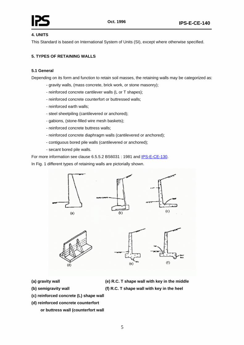
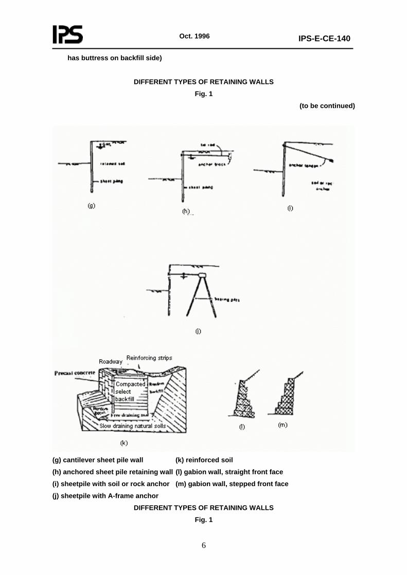
In Fig. 1 different types of retaining walls are pictorially shown.
(a) gravity wall (e) R.C. T shape wall with key in the middle
(b) semigravity wall (f) R.C. T shape wall with key in the heel
(c) reinforced concrete (L) shape wall
(d) reinforced concrete counterfort
or buttress wall (counterfort wall
Oct. 1996
IPS-E-CE-140
6
has buttress on backfill side)
DIFFERENT TYPES OF RETAINING WALLS
Fig. 1
(to be continued)
(g) cantilever sheet pile wall (k) reinforced soil
(h) anchored sheet pile retaining wall (l) gabion wall, straight front face
(i) sheetpile with soil or rock anchor (m) gabion wall, stepped front face
(j) sheetpile with A-frame anchor
DIFFERENT TYPES OF RETAINING WALLS
Fig. 1
Oct. 1996
IPS-E-CE-140
7
6. FACTORS AFFECTING SELECTION OF TYPE OF RETAINING WALLS
The available options and constraints for selection of retaining wall types are generally based on many factors: i.e. (physical, economical, technological, etc.), which should be carefully considered in each special case before any selection is made. The main factors affecting this procedure, may, without any limitation, be categorized as follows:
- Foundation materials and conditions
- Physical constraints
- Availability of construction materials and equipments
- Economic considerations
- Aesthetic aspects
- Soil characteristics and presence of ground water
It should, however, be noted that many of these factors are interlinked and by means of engineering judgment, one should select the most suitable type in each case which eventually should be verified by economic evaluation and appraisal.
7. FORCES ACTING ON RETAINING WALLS
A retaining wall should be designed to resist all forces acting on it during its lifetime. The most important forces being lateral earth pressure; however other forces may equally be important, among which pore-water pressure, earthquake forces, lateral pressures due to surcharges, lateral forces due to ice formation, thrusts due to temperature, pressures due to soil swelling, and lateral pressures due to compaction during construction may be mentioned. The following paragraphs give a brief description of the above-mentioned forces.
7.1 Lateral Earth Pressure
7.1.1 General
Retaining walls should be designed to withstand forces due to the soil masses. The magnitude of the earth pressure imposed against the structure, depends upon the soil type to be retained, ground water conditions and to the amount of displacements the wall can undergo. There are three types of conditions that the retaining walls may be subjected to:
- Movement of the wall away from the soil mass which will result in an active earth pressure.
- Movement of the wall toward the soil mass which will result in a passive earth pressure.
- The condition in which no movement of the wall will take place, the force produced is called at rest earth pressure.
It is very important that the designer should distinguish between the different conditions and take the proper lateral forces into consideration.
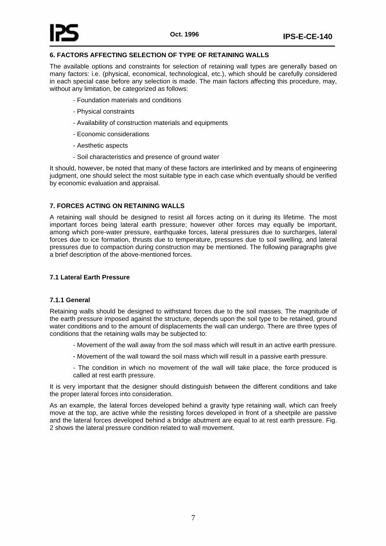
As an example, the lateral forces developed behind a gravity type retaining wall, which can freely move at the top, are active while the resisting forces developed in front of a sheetpile are passive and the lateral forces developed behind a bridge abutment are equal to at rest earth pressure. Fig. 2 shows the lateral pressure condition related to wall movement.
Oct. 1996
IPS-E-CE-140
8
LATERAL PRESSURE CONDITION RELATED TO WALL MOVEMENT
Fig. 2
7.1.2 Active earth pressure
The magnitude of active earth pressure depends on the type of soil: i.e. cohesive or cohesionless, the angle of friction between wall and soil, and the inclination angle of earth slopes behind the wall. The general formula for computing the amount of active earth pressure and related nomenclature is given in Appendix "A". The distribution of active earth pressure behind the free moving retaining walls is triangular and the point of application of the force is located at 1/3 of the height of the wall from the bottom. In case of anchored sheetpiling the distribution of active earth pressure is different, for details of which refer to Clause 51.3 of BS 6349: Part 1: 2000.
7.1.3 Passive earth pressure
The general formula for computation of passive earth pressure is given in Appendix "A". The distribution of passive earth pressure for ordinary retaining walls is triangular and the point of application of the force is at 1/3 of the height of force triangle from the bottom, while for anchored sheet-piling it is different. For details refer to BS 6349: Part 1: 2000.
7.1.4 At rest earth pressure
The amount of at rest earth pressure is greater than active, but smaller than the passive one. At rest earth pressure generally will develop when the top of the wall may not move freely (as in the case of bridge abutments, basement walls, or due to swelling effect of clay soils or the effect of compacting backfills around the walls).
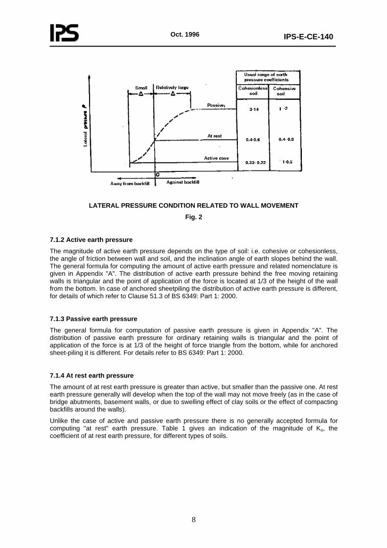
Unlike the case of active and passive earth pressure there is no generally accepted formula for computing "at rest" earth pressure. Table 1 gives an indication of the magnitude of Ko, the coefficient of at rest earth pressure, for different types of soils.
Oct. 1996
IPS-E-CE-140
9
TABLE 1 - COEFFICIENT OF EARTH PRESSURE AT REST
SOIL TYPE KO
Loose sand, saturated Dense sand, saturated Dense sand, dry Loose sand, dry Compacted, residual clay Compacted, residual clay Organic salty clay, undisturbed Kaolin, undisturbed Sea clay, undisturbed Quick clay
0.46 0.36 0.49
0.64 0.42 0.66
0.57 0.64 - 0.70
0.48 0.52
7.1.5 Earth pressure for cohesive soils
Earth pressure magnitudes given in 7.1.2 to 7.1.4 are related to cohesionless soils. In case of cohesive soils, due to cohesion forces, tension cracks may develop as a result of wall deflection, along which the soil has no shear resistance. Theoretically, the wedge of soil formed by tension cracks, adds no pressure to the wall and therefore would be substracted from the amount of lateral pressure. However, this condition might be valid only over a short term, for the long term, due to the possibility of cracks being filled with water, the tension zone should not be relied on and it is prudent not only to neglect the reducing effect of cohesion but also when cohesive soils must be used for backfills behind a retaining wall, the wall should be designed to resist at least an at-rest lateral pressure as indicated in 7.1.3. Generally the use of such soil should be avoided wherever possible.
7.2 Surcharges
The soil supported by many types of retaining structures may be subjected to external loads, i.e. loads not derived from the soil itself, these loads are called "surcharges". If there is a uniformly distributed surcharge "q" on the backfill, the total force exerted to the wall will be equal to:
Ps = qHka
Where:
Ps = total surcharge force exerted to the wall,
q = uniformly distributed surcharge over the backfill,
H = height of the wall,
ka = coefficient of active earth pressure.
For determining the point of application, it is generally required to take moments about a convenient point. In special cases, where the pressure distribution due to surcharge is rectangular, the point of application will be at ½ of height of the wall.
7.3 Water Pressure
Lateral soil pressures against a wall should be computed by using the effective unit weight of the retained soil. If the groundwater level rises into the backfills behind a retaining wall because of either a changing ground water condition or percolating surface water, the lateral pressure against the wall are changed. For soil below the water table a submerged unit weight is used, and the related lateral soil pressure becomes approximately half of the nonsubmerged value. Additionally however, a hydrostatic pressure develops against the back of the wall. The combined effect of soil and water pressures causes overturning moments and sliding forces to be greater than for the condition of no water. To eliminate the opportunity for a great height of water to build up behind a wall, through-the-wall weep holes or a collectordrainage system, or both, are commonly provided and are considered to be an essential part of the design and construction, (see Clause 9.2). It should be noted that even in the case of providing measures to lower the ground water behind the
Oct. 1996
IPS-E-CE-140
10
retaining walls it is necessary to consider the water pressure in stability computations, because there is always the possibility of clogging of filters and inefficient functioning of drainage system, which may endanger the stability of the structure during its lifetime.
7.4 Earthquake Forces
Ground motion during earthquake tends to increase the earth pressure beyond the static condition. Retaining walls with horizontal backfills designed with a safety factor of 1.5 for static loading, may be expected to withstand horizontal accelerations up to 0.2g, for larger accelerations and for walls with sloping backfills, additional allowance should be made for earthquake forces. In addition to the increased soil pressure due to earthquake the following additional forces may develop accordingly:
- If the backfill is submerged, the wall will be subjected to additional dynamic water pressure.
- Concrete or masonry inertia forces due to horizontal and vertical earthquake accelerations which are the products of the weight of the wall and the horizontal and vertical seismic coefficients respectively should be considered.
- The effect of earthquake on the surcharges should also be taken into account.
In relation to minimum earthquake acceleration, the requirements of Iranian Building Code, Standard No. 2800, Clause 2.1 should be regarded. It should be noted that the distribution of earth pressures due to earthquake, differs from the static one, thus, it is recommended that the distribution diagram of forces should be drawn separately for static and dynamic components. Generally, while the point of application for static forces is at 1/3 of the height of the wall, those of the dynamic ones are at 1/2 to 2/3 of height of the wall depending on active or passive conditions. Attention should also be paid to the potential of liquefaction of foundation materials especially in fine grained soils. For details refer to IPS-E-CE- 110 "Soil Engineering".
7.5 Other Forces
In addition to the forces mentioned in 7.1 to 7.4, under certain circumstances several other forces may develop behind retaining walls. In the following paragraphs such forces are described:
7.5.1 Forces due to ice formation
When soil is exposed to a freezing climate for a considerable period, most of the pore water in the soil is subjected to freezing, and as water crystallizes, its volume expands and eventually it will form ice lenses which will produce large lateral forces on the retaining walls. In free draining soils, due to absence of water, this force may be eliminated, but if the situation makes it indispensable to utilize fine ground soils, adequate provisions should be made to accommodate for such lateral forces which might be as high as 1 ton per meter length of the wall acting on top of it. However it should be noted that, such force is to be taken only for analysis of structural members of the wall (i.e. stem in reinforced concrete retaining walls) and should be omitted from all calculations for sliding, because the ground in front of the wall will be frozen also and it will resist the shear caused by ice pressure behind the structure.
7.5.2 Thrust due to temperature
Walls providing restraint to members which may undergo thermal expansion and contraction may develop unwanted stresses. This problem can be solved by backing the restraint with rollers, hinges, or expansion joints, whenever these provisions might not be possible, the above mentioned thrust should be considered in computations.
7.5.3 Pressure due to swelling of soil
If an expansive clay is placed behind a retaining wall and becomes wet, large pressures may be developed. The problem can be somewhat alleviated by placing the clay under carefully controlled
Oct. 1996
IPS-E-CE-140
11
conditions of no lumps and at a water content considerably above optimum. The problem can be considerably alleviated by using granular backfill.
7.5.4 Loads during construction
In practice most of earth-retaining walls are built before the soil to be retained is placed. Method of back-fill placement and type of the soil, have an important effect on the lateral pressures that eventually act on the wall. This fact is especially important for highway bridge abutments, where proper compaction of backfills is very noticeable to road users because any settlement in the adjacent fill gives a very bad ride as vehicles cross from the fill to the bridge deck. This necessitates use of heavy rollers for compaction of the backfills which results in a temporary increase in lateral pressure on the wall. The load due to compaction may be reduced if the roller is prevented from coming close to the wall, however for design purposes it would seem prudent to assume the worst case; i.e. that the roller will come hard up the back of the wall. Generally for these situations design on the basis of a lateral pressure condition in the at-rest range is more appropriate than assuming an active pressure condition; this is especially prevalent for analysis of the stem of reinforced concrete walls. For overall stability computations, however, active earth pressure values may be used, since the wall must translate and/or rotate prior to failure which reduce the lateral pressure to active values, regardless of what the pressure is prior to wall movement.
8. METHODS AND PROCEDURES FOR ANALYSIS OF RETAINING WALLS
Under clauses 8.1 to 8.1.4, the general principles of selection of relevant soil parameters for design, methods of stability analysis for retaining walls, foundation bearing capacity and overall stability of slopes containing the retaining walls are discussed.
8.1 Selection of Relevant Soil Parameters for Design
As it was noted in clauses 7.1 to 7.5 of this Engineering Standard, the magnitude of earth pressure mobilized behind a retaining wall will be related to:
- Wall/soil placement techniques
- Wall movement relative to the soil
- Shear strength developed between the wall and the soil
- Shear strength of the soil itself
- Wall, soil, groundwater geometry
- External loads
Thus, it is essential that the designer correctly deduces the wall/soil placement technique to be used, the direction of wall movement relative to the soil, and the probable worst groundwater conditions. In general, the designer should acquire a knowledge of :
- The geometry of the problem-height and inclination of supported soil face, geometry of ground surface, distribution of soil types in three dimensions, position of any external loads, and position of any existing structures to be protected.
- The bulk density of the soil for undisturbed soil.
- Groundwater conditions. These are required for the worst conceivable condition in the life of the structure. It may be necessary to carry out seepage studies, using flow net sketching in order to obtain an estimate of the final groundwater level, and porewater pressure variations on the shear surface and the back of the wall. Techniques for estimating water pressures is discussed in IPS-E-CE-110.
- Soil strength parameters. These will vary according to the type of problem. In general the designer will require a good knowledge of the peak effective strength parameters (c’,φ ’) for the soil that the wall is to support. For details of tests and procedures related to obtaining the necessary soil parameters refer to IPS-E-CE-110.
Oct. 1996
IPS-E-CE-140
12
8.1.1 Soil investigation
Details of soil investigation program and tests necessary are given in IPS-E-CE-110. As a general rule the following points should be regarded in investigations for obtaining necessary soil parameters to design retaining walls:
- The boring’s should be extended to strata of adequate bearing capacity and should penetrate all deposits which are unsuitable for foundation purposes, such as unconsolidated fill, peat, organic silt and very soft and compressible clay. The soft strata should be penetrated even when they are covered with a surface layer of high bearing capacity.
- Except in the case of very heavy loads or when seepage or other considerations are governing, the boring’s may be stopped when rock is encountered or after a short penetration into strata of exceptional bearing capacity and stiffness, provided it is known from explorations in the vicinity or the general stratigraphy of the area that these strata have adequate thickness or are underlain by still stronger formations. When these conditions are not fulfilled, some of the boring’s must be extended until it has been established that the strong strata have adequate thickness irrespective of the character of the underlying material.
- When the structure is to be founded on rock, it must be verified that bedrock and not boulders have been encountered. It should, however, be noted that, in the case of small projects, where the possibility of performing independent soil investigations does not exist, relevant informations on soils from existing projects on the neighboring areas should be collected as much as possible.
8.1.2 Ground water
The loads on earth retaining structures are very significantly influenced by groundwater conditions. Therefore it is essential that ground investigation for earth-retaining structures should be made as fully as possible. The groundwater problem is important not only for the design of the permanent works; but also it has very serious implications for construction costs because of its influence on the difficulty of carrying out groundworks. In this respect it is important to know in some detail not only the geometry of the subsoil and the forms of groundwater regime, but also the permeability of each soil type (in both the horizontal and vertical directions if possible). For detailed information on ground water investigations refer to clause 23 BS 5930: 1999 and IPS-E-CE-110.
8.1.3 Basic and index properties of soil
Basic properties include the fundamental characteristics of geologic materials and are used primarily for identification and correlation between similar materials.
Index properties are those that indicate the type and condition of the soil. Basic and index property data are required for material identification and classification and as input for engineering analysis. In addition, correlations based on basic and index properties with data obtained from other investigations in which extensive testing was performed or engineering properties were determined by back analysis of failures provide data for preliminary studies and analysis as well as a check on the reasonableness of data obtained during investigation.
For details of relevant tests refer to IPS-E-CE-110.
8.1.4 Soil strength parameters
a) Granular Soils
The effective strength parameters of granular soils are a function of particle size distribution, soil density, imposed stress level, angularity and cementation. They could be obtained from laboratory tests of representative disturbed samples obtained during in-situ investigations. Since the in situ density and horizontal stress level in the soil are unknown, a
Oct. 1996
IPS-E-CE-140
13
range of tests should be carried out at different densities and effective stress levels. Tests can be carried out either in the triaxial apparatus or in the shear box; in both cases the tests should be of a "drained type", i.e. volume change is allowed to occur during shearing and the rate of shear should be slow enough to allow excess pore pressures set up as a result of the shearing process to be dissipated. Effective cohesion will be expected to be zero for a clean uncemented granular soil. Since it is very difficult to obtain good quality undisturbed samples for laboratory testing, strength parameters may be obtained from empirical relationship by the SPT (standard penetration test) correlations.
b) Cohesive Soils
Except in the case of very small structures and in the absence of test data, where only approximate values of strength parameters for preliminary design can be obtained, from sample description, the strength properties of cohesive soils must always be obtained from testing of good-quality undisturbed soil samples.
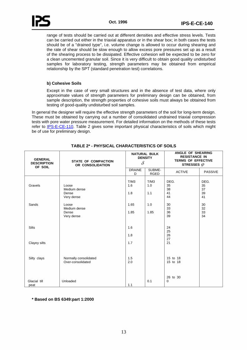
In general the designer will require the effective strength parameters of the soil for long-term design. These must be obtained by carrying out a number of consolidated undrained triaxial compression tests with pore water pressure measurement. For detailed information on the methods of these tests refer to IPS-E-CE-110. Table 2 gives some important physical characteristics of soils which might be of use for preliminary design.
TABLE 2* - PHYSICAL CHARACTERISTICS OF SOILS
NATURAL BULK DENSITY δ
ANGLE OF SHEARING RESISTANCE IN
TERMS OF EFFECTIVE STRESSES ϕ
GENERAL DESCRIPTION
OF SOIL
STATE OF COMPACTION OR CONSOLIDATION
DRAINED
SUBME- RGED ACTIVE PASSIVE
Gravels Sands Silts Clayey silts Silty clays Glacial till peat
Loose Medium dense Dense Very dense Loose Medium dense Dense Very dense Normally consolidated Over-consolidated Unloaded
T/M3 1.6 1.8 1.65 1.85 1.6 1.8 1.7 1.5 2.0 1.1
T/M3 1.0 1.1 1.0 1.85 0.1
DEG. 35 38 41 44 30 33 36 39 24 25 26 27 21 15 to 18 15 to 18 26 to 30 0
DEG. 35 37 39 41 30 32 33 34
* Based on BS 6349:part 1:2000
Oct. 1996
IPS-E-CE-140
14
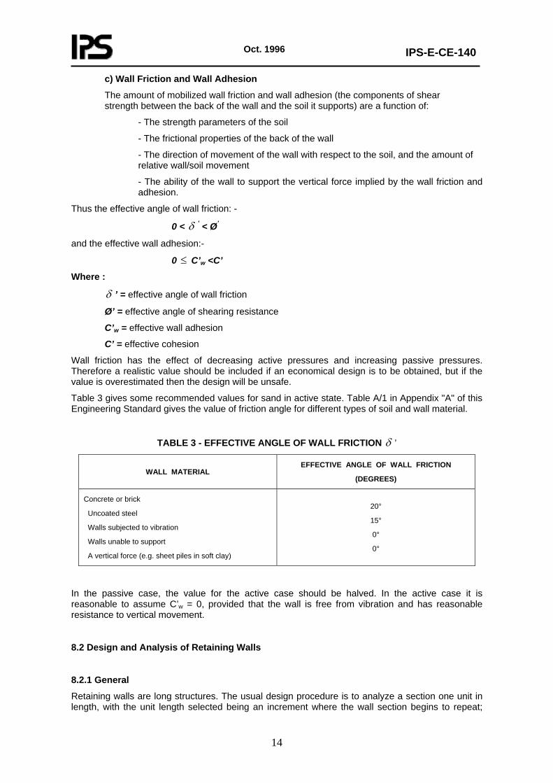
c) Wall Friction and Wall Adhesion
The amount of mobilized wall friction and wall adhesion (the components of shear strength between the back of the wall and the soil it supports) are a function of:
- The strength parameters of the soil
- The frictional properties of the back of the wall
- The direction of movement of the wall with respect to the soil, and the amount of relative wall/soil movement
- The ability of the wall to support the vertical force implied by the wall friction and adhesion.
Thus the effective angle of wall friction: -
0 < δ ’ < Ø’
and the effective wall adhesion:-
0 ≤ C’w <C’
Where :
δ ’ = effective angle of wall friction
Ø’ = effective angle of shearing resistance
C’w = effective wall adhesion
C’ = effective cohesion
Wall friction has the effect of decreasing active pressures and increasing passive pressures. Therefore a realistic value should be included if an economical design is to be obtained, but if the value is overestimated then the design will be unsafe.
Table 3 gives some recommended values for sand in active state. Table A/1 in Appendix "A" of this Engineering Standard gives the value of friction angle for different types of soil and wall material.
TABLE 3 - EFFECTIVE ANGLE OF WALL FRICTION δ ’
WALL MATERIAL EFFECTIVE ANGLE OF WALL FRICTION
(DEGREES)
Concrete or brick
Uncoated steel
Walls subjected to vibration
Walls unable to support
A vertical force (e.g. sheet piles in soft clay)
20°
15°
0°
0°
In the passive case, the value for the active case should be halved. In the active case it is reasonable to assume C’w = 0, provided that the wall is free from vibration and has reasonable resistance to vertical movement.
8.2 Design and Analysis of Retaining Walls
8.2.1 General
Retaining walls are long structures. The usual design procedure is to analyze a section one unit in length, with the unit length selected being an increment where the wall section begins to repeat;
Oct. 1996
IPS-E-CE-140
15
walls whose general cross section is constant for a long length would consider a segment one meter in length, whereas a counterfort or buttressed wall would consider a section that extends the center-to-center distance between buttresses or counterforts. The height of soil to be retained will usually vary along the length of the wall, and with homogeneous backfill and foundation conditions the most severe design loading occurs where the height is greatest. The wall cross section required for this crucial location is also assumed for adjacent locations, although the actual height constructed may be lower. For long walls of varying height requirements, a separate design can be provided for the different segments in order to economize on materials.
Conversely, for concrete walls of limited length that retain an approximately constant height of soil, the critical cross section may be used for the entire wall, because savings related to labor and forming procedures associated with constructing the wall offset the extra material used. A proper retaining wall design and analysis should satisfy the following requirements:
1) The structural components of the wall (the base and the stem) should be capable of resisting the internal shears and bending moments developing as a result of soil and other loading.
2) The wall structure should be safe against overturning.
3) The wall structure should be safe against sliding.
4) The bearing capacity of the foundation material supporting the wall should not be exceeded.
5) Settlement and distortion of the wall due to compression of the foundation soil should be limited to a tolerable value.
6) The overall stability of slopes containing the retaining wall should be guaranteed.
Notes:
1) Structural analysis of retaining wall is not covered in this Standard and reference is made to IPS-E-CE-200 "Engineering Standard for Concrete Structures" in this respect.
2) The procedures mentioned in this Standard are mostly applicable to retaining walls, being founded on shallow foundations i,e. gravity walls,reinforced concrete, etc. Those types of retaining structures having deep foundations like sheetpiling, gravity walls resting over piles are not discussed here in detail, since they are generally common with maritime structures and reference should be made to BS 6349 parts 1 to 7 in this respect.
3) Details of stability analysis for various kinds of retaining walls are somehow different and a detailed discussion for each type will not be made here.
4) Points 4 and 5, of the above mentioned parameters are not to be discussed in detail here, for which reference is made to IPS-E-CE-120 "Foundations".
5) For details of slope stability analysis refer to IPS-E-CE-110.
In clauses 8.2.2 to 8.2.6 the above-mentioned items are discussed briefly.
8.2.2 Tilting and overturning
Although a certain amount of wall tilting is desirable so that the active pressure concept is valid, excessive tilting is undesirable and should be prevented. The stability against overturning is evaluated by comparing moments about an assumed axis of rotation (typically the toe of the wall) which result from forces acting to cause overturning and forces acting to resist overturning. The ratio of resisting moments to those causing overturning is the factor of safety against overturning; a value of 2 or greater is normally desired. See Clause 8.2.4.
Oct. 1996
IPS-E-CE-140
16
8.2.3 Sliding
Retaining walls must provide adequate resistance against sliding. The resisting forces against sliding are mainly due to friction of wall base and the foundation materials and partly due to the passive earth pressure of the soil which may develop in front of the retaining wall as the wall tends to slide towards it. If the soil in front of the wall is excavated or eroded, after the wall construction,during its lifetime, then the passive pressure component will not anymore be available and the sliding instability may be expected. So it is prudent not to take this resisting force into consideration in stability computations, except in such situations that it is fully improbable to anticipate removal of earth in front of the wall.
8.2.4 Safety factors
Safety factor may be defined as the ratio of resisting forces or moments to the forces or moments which tend to instabilize the wall. To insure proper functioning of the wall during its lifetime, adequate safety factors should be adopted. The safety factor against sliding should be at least 1.5 for cohesionless and about 2.0 for cohesive backfill. The usual safety factor against overturning with respect to the toe is 1.5, with a value or 2.0 suggested for cohesive soil. Safety factors for basement walls and bridge abutments are computed similarly except that the wall is usually rigid and movements which are necessary to achieve active pressure are restrained, resulting in larger wall pressures. These larger pressures, generally on the order of Ko conditions, are used for both structural-design and for wall-stability computations. Stability of the base against a bearing-capacity failure is achieved by using a suitable safety factor with the ultimate bearing pressure, where the safety factor is usually taken as 2.0 for granular soils and 3.0 for cohesive soils; see Clause 8.2.5.
To ensure adequate factor of safety under earthquake condition, the design shall be such that the factor of safety against sliding shall be 1.2 and the resultant of all the forces including earthquake force shall fall within the middle threefourths of the base width provided. In addition, bearing pressure in soil should not exceed the permissible limit.
8.2.5 Retaining wall foundation bearing capacity and settlement.
Foundation bearing pressure is computed by determining stress distribution over the wall base using the formula:
)61(B
eBVq ±
=
where:
q = Foundation pressure at the toe or heel using ±signs respectively
V = Total vertical component of foundation reaction
B = Width for the wall base
e = Distance from toe to point where foundation reaction is applied
The maximum foundation pressure thus obtained should not exceed the soil bearing capacity. Adequate safety factors, depending on the soil type should be considered, see Clause 8.2.4. If the bearing capacity is not adequate then pile foundations should be considered. Walls with base on granular soils should undergo most of the expected settlement by the time the wall construction and backfull are completed. Walls on cohesive soils for which consolidation theory is applicable will continue to settle for some time after completion of construction. The resultant force should be kept near the middle of the base for these soils to keep the settlement relatively uniform and reduce tilting.
When the footing is on rock, two items must be considered. First, there must be sufficient rotation of the base and wall so that active pressure is developed. This can be accomplished by placing an earth pad beneath the base 150 to 300 mm thick, or constructing the stem with sufficient flexibility to
Oct. 1996
IPS-E-CE-140
17
yield with the soil pressure. The second problem is to avoid high toe pressures, which may break the toe away from the remainder of the base. This can be avoided by proportioning the footing so that the resultant falls near its center. Longitudinal differential settlement is inevitable because of the natural variability of soil, and should be allowed for by the inclusion of construction joints at least every 6 to 10 m along the wall.
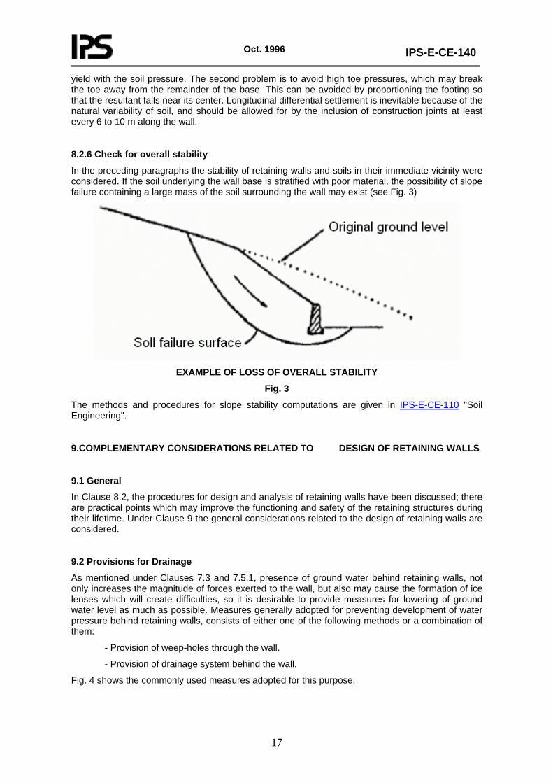
8.2.6 Check for overall stability
In the preceding paragraphs the stability of retaining walls and soils in their immediate vicinity were considered. If the soil underlying the wall base is stratified with poor material, the possibility of slope failure containing a large mass of the soil surrounding the wall may exist (see Fig. 3)
EXAMPLE OF LOSS OF OVERALL STABILITY
Fig. 3
The methods and procedures for slope stability computations are given in IPS-E-CE-110 "Soil Engineering".
9.COMPLEMENTARY CONSIDERATIONS RELATED TO DESIGN OF RETAINING WALLS
9.1 General
In Clause 8.2, the procedures for design and analysis of retaining walls have been discussed; there are practical points which may improve the functioning and safety of the retaining structures during their lifetime. Under Clause 9 the general considerations related to the design of retaining walls are considered.
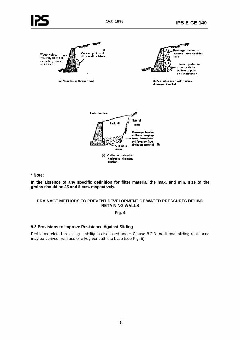
9.2 Provisions for Drainage
As mentioned under Clauses 7.3 and 7.5.1, presence of ground water behind retaining walls, not only increases the magnitude of forces exerted to the wall, but also may cause the formation of ice lenses which will create difficulties, so it is desirable to provide measures for lowering of ground water level as much as possible. Measures generally adopted for preventing development of water pressure behind retaining walls, consists of either one of the following methods or a combination of them:
- Provision of weep-holes through the wall.
- Provision of drainage system behind the wall.
Fig. 4 shows the commonly used measures adopted for this purpose.
Oct. 1996
IPS-E-CE-140
18
* Note:
In the absence of any specific definition for filter material the max. and min. size of the grains should be 25 and 5 mm. respectively.
DRAINAGE METHODS TO PREVENT DEVELOPMENT OF WATER PRESSURES BEHIND RETAINING WALLS
Fig. 4
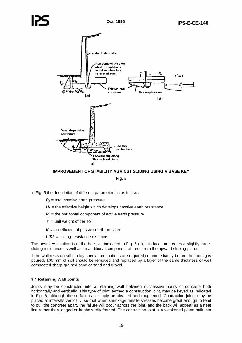
9.3 Provisions to Improve Resistance Against Sliding
Problems related to sliding stability is discussed under Clause 8.2.3. Additional sliding resistance may be derived from use of a key beneath the base (see Fig. 5)
Oct. 1996
IPS-E-CE-140
19
IMPROVEMENT OF STABILITY AGAINST SLIDING USING A BASE KEY
Fig. 5
In Fig. 5 the description of different parameters is as follows:
Pp = total passive earth pressure
HP = the effective height which develops passive earth resistance
Ph = the horizontal component of active earth pressure
γ = unit weight of the soil
K P = coefficient of passive earth pressure
L’&L = sliding-resistance distance
The best key location is at the heel, as indicated in Fig. 5 (c), this location creates a slightly larger sliding resistance as well as an additional component of force from the upward sloping plane.
If the wall rests on silt or clay special precautions are required,i.e. immediately before the footing is poured, 100 mm of soil should be removed and replaced by a layer of the same thickness of well compacted sharp-grained sand or sand and gravel.
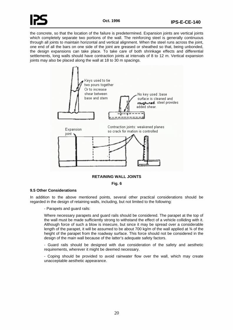
9.4 Retaining Wall Joints
Joints may be constructed into a retaining wall between successive pours of concrete both horizontally and vertically. This type of joint, termed a construction joint, may be keyed as indicated in Fig. 6, although the surface can simply be cleaned and roughened. Contraction joints may be placed at intervals vertically, so that when shrinkage tensile stresses become great enough to tend to pull the concrete apart, the failure will occur across the joint, and the back will appear as a neat line rather than jagged or haphazardly formed. The contraction joint is a weakened plane built into
Oct. 1996
IPS-E-CE-140
20
the concrete, so that the location of the failure is predetermined. Expansion joints are vertical joints which completely separate two portions of the wall. The reinforcing steel is generally continuous through all joints to maintain horizontal and vertical alignment. When the steel runs across the joint, one end of all the bars on one side of the joint are greased or sheathed so that, being unbonded, the design expansions can take place. To take care of both shrinkage effects and differential settlements, long walls should have contraction joints at intervals of 8 to 12 m. Vertical expansion joints may also be placed along the wall at 18 to 30 m spacings.
RETAINING WALL JOINTS
Fig. 6
9.5 Other Considerations
In addition to the above mentioned points, several other practical considerations should be regarded in the design of retaining walls, including, but not limited to the following:
- Parapets and guard rails:
Where necessary parapets and guard rails should be considered. The parapet at the top of the wall must be made sufficiently strong to withstand the effect of a vehicle colliding with it. Although force of such a blow is insecure, but since it may be spread over a considerable length of the parapet, it will be assumed to be about 700 kg/m of the wall applied at ¾ of the height of the parapet from the roadway surface. This force should not be considered in the design of the main wall because of the latter’s adequate safety factors.
- Guard rails should be designed with due consideration of the safety and aesthetic requirements, wherever it might be deemed necessary.
- Coping should be provided to avoid rainwater flow over the wall, which may create unacceptable aesthetic appearance.
Oct. 1996
IPS-E-CE-140
21
PART TWO
SLOPE PROTECTION
1. GENERAL
In part one of this Engineering Standard, different types of structures to retain earth masses has been discussed, where the masses could not assume their natural slopes. In this part, stabilization and protection of soil and rock slopes are considered. Stability of man-made slopes (cuttings and embankments) are discussed in clause 9 of IPS-E-CE-110," Soil Engineering". Stability of natural slopes exposed to air is considered in this Standard. Shore protection and protection of slopes under water is discussed in IPS-G-CE-470 "Onshore Facilities" however several aspects may be relevant to both fields.
2. TYPES OF SLOPE STABILIZATION METHODS
2.1 Soils
2.1.1 General
There are different types of slope stabilization methods for soils among which the following may be mentioned:
- Drainage provisions
- Ground anchors
- Improvement of soil parameters
In Clauses 2.1.2 to 2.1.4 brief description on the above mentioned methods are given.
2.1.2 Drainage provisions
Reducing pore pressures within the slope can be an effective and economical measure. Details of methods of drainage are given in Clause 6.5.4 of BS 6031:1981. One or a combination of methods described in that clause may be adopted.
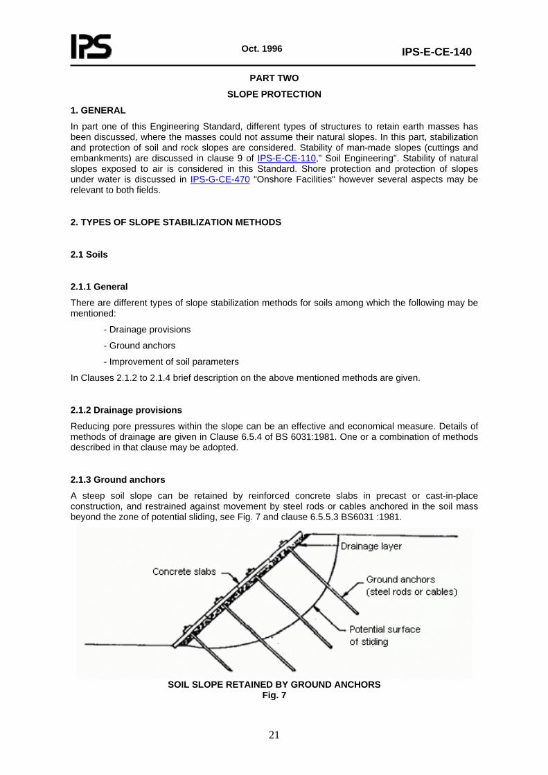
2.1.3 Ground anchors
A steep soil slope can be retained by reinforced concrete slabs in precast or cast-in-place construction, and restrained against movement by steel rods or cables anchored in the soil mass beyond the zone of potential sliding, see Fig. 7 and clause 6.5.5.3 BS6031 :1981.
SOIL SLOPE RETAINED BY GROUND ANCHORS
Fig. 7
Oct. 1996
IPS-E-CE-140
22
2.1.4 Improvement of soil parameters
Grouting by physico-chemical methods may be considered as a means of stabilizing a soil mass to permit steep slopes, but its principal use is as a remedial measure. Descriptions of the physico-chemical methods are given in Clause 11.4 of BS 6031:1981.
2.2 Rocks
2.2.1 General
There are various methods for reinforcing or retaining rock slopes. Some of the common types of rock slope stabilization methods are mentioned as follows:
a) concrete pedestals for overhangs;
b) rock bolts for jointed masses;
c) bolts and concrete straps for intensely jointed masses;
d) cable anchors to increase support depth;
e) wire mesh to constrain falls;
f) shotcrete to reinforce loose rock, with bolts and drains;
h) shotcrete to retard weathering and slaking of shales.
As these methods have limited application in the Petroleum Industries the details are not discussed in this Standard.
3. SURFACE PROTECTION OF SLOPES
3.1 General
Slopes in soft rock or soil are prone to serious erosions during heavy rain and some rock slopes suffer from deterioration due to weathering when exposed. The protection of the surface of such slopes can be a serious problem. In this part of the Engineering Standard different surface protection methods are considered.
3.2 Types of Protection Methods
The principal methods of slope protection can be categorized without limitation as follows:
a) Vegetative cover
b) Hand placed riprap
c) Dumped rockfill
d) Precast concrete elements
e) Masonry
f) Gabions
The methods mentioned under (b) to (f) are common in maritime structures, and sea defence works, for which reference is made to IPS-G-CE-470: "Onshore Facilities". In the following clauses, brief description are given about the abovementioned methods.
3.2.1 Vegetative cover
The most widely used and effective form of protection is vegetative cover. It is only effective in climatic conditions where the selected vegetation is able to thrive and self propagate. Trees provide
Oct. 1996
IPS-E-CE-140
23
better cover and deeper root growth than that provided by grass. The type of tree should be suitable for the surroundings and care should be taken that infiltration by roots does not damage drainage or services. For further detailed information about vegetative cover refer to Clause 11.4.2 of BS 6031:1981.
3.2.2 Hand placed riprap
This type of protection is generally used for water front structures and where severe damages from wave action is anticipated. The size of ripraps should be chosen properly so that they can resist the forces due to waves. To avoid migration of fine grained soils a layer of filler should be provided.
3.2.3 Dumped rockfill
Dumped rockfill protection is basically the same as hand placed riprap, the only difference is that the sizes of stones is too large to be placed by hand and generally they are dumped by a truck and spread over the slopes. This method is generally used where severe conditions exist due to storms and surges and the size of the individual stones to resist the forces should be large.
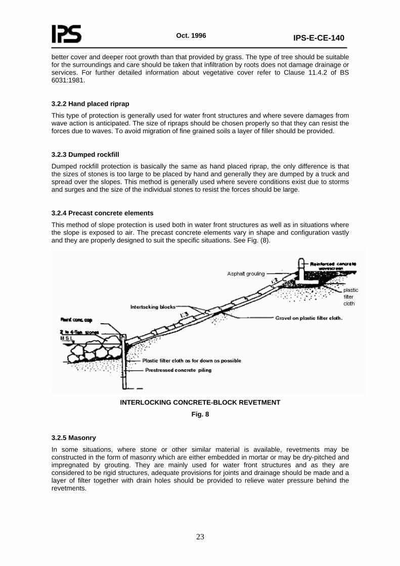
3.2.4 Precast concrete elements
This method of slope protection is used both in water front structures as well as in situations where the slope is exposed to air. The precast concrete elements vary in shape and configuration vastly and they are properly designed to suit the specific situations. See Fig. (8).
INTERLOCKING CONCRETE-BLOCK REVETMENT
Fig. 8
3.2.5 Masonry
In some situations, where stone or other similar material is available, revetments may be constructed in the form of masonry which are either embedded in mortar or may be dry-pitched and impregnated by grouting. They are mainly used for water front structures and as they are considered to be rigid structures, adequate provisions for joints and drainage should be made and a layer of filter together with drain holes should be provided to relieve water pressure behind the revetments.
Oct. 1996
IPS-E-CE-140
24
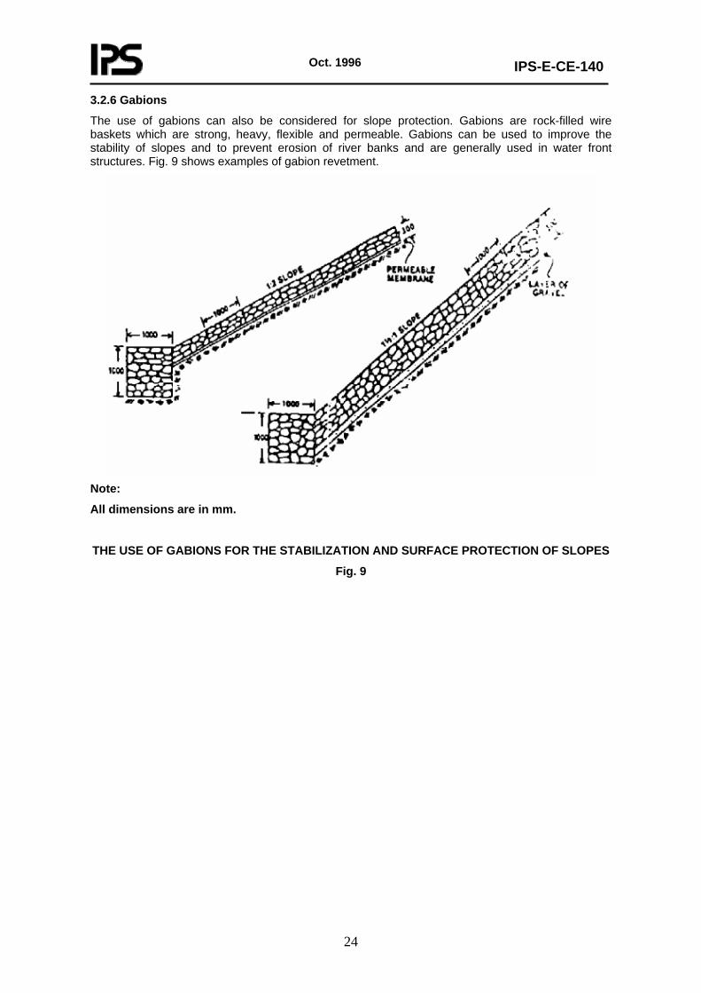
3.2.6 Gabions
The use of gabions can also be considered for slope protection. Gabions are rock-filled wire baskets which are strong, heavy, flexible and permeable. Gabions can be used to improve the stability of slopes and to prevent erosion of river banks and are generally used in water front structures. Fig. 9 shows examples of gabion revetment.
Note:
All dimensions are in mm.
THE USE OF GABIONS FOR THE STABILIZATION AND SURFACE PROTECTION OF SLOPES
Fig. 9
Oct. 1996
IPS-E-CE-140
25
APPENDICES
APPENDIX A LATERAL EARTH PRESSURE COMPUTATIONS
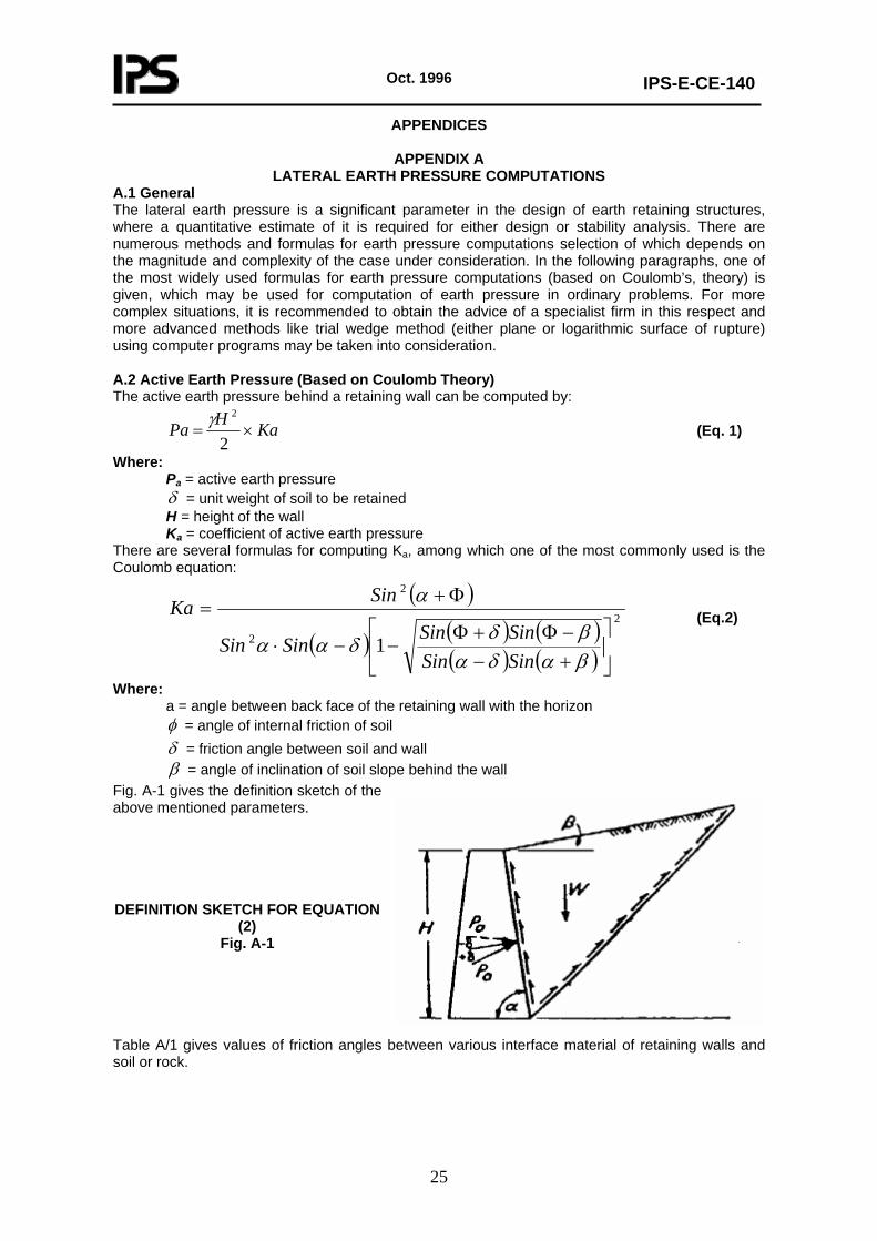
A.1 General The lateral earth pressure is a significant parameter in the design of earth retaining structures, where a quantitative estimate of it is required for either design or stability analysis. There are numerous methods and formulas for earth pressure computations selection of which depends on the magnitude and complexity of the case under consideration. In the following paragraphs, one of the most widely used formulas for earth pressure computations (based on Coulomb’s, theory) is given, which may be used for computation of earth pressure in ordinary problems. For more complex situations, it is recommended to obtain the advice of a specialist firm in this respect and more advanced methods like trial wedge method (either plane or logarithmic surface of rupture) using computer programs may be taken into consideration. A.2 Active Earth Pressure (Based on Coulomb Theory) The active earth pressure behind a retaining wall can be computed by:
KaHPa ×=2
2γ (Eq. 1)
Where: Pa = active earth pressure δ = unit weight of soil to be retained H = height of the wall Ka = coefficient of active earth pressure
There are several formulas for computing Ka, among which one of the most commonly used is the Coulomb equation:
( )
( ) ( ) ( )( ) ( )
2
2
2
1 ⎥⎦
⎤⎢⎣
⎡
+−−Φ+Φ
−−⋅
Φ+=
βαδαβδδαα
α
SinSinSinSinSinSin
SinKa (Eq.2)
Where: a = angle between back face of the retaining wall with the horizon φ = angle of internal friction of soil δ = friction angle between soil and wall β = angle of inclination of soil slope behind the wall
Fig. A-1 gives the definition sketch of the above mentioned parameters.
DEFINITION SKETCH FOR EQUATION
Fig. A-1
aterial of retaining walls and soil or rock.
(2)
Table A/1 gives values of friction angles between various interface m
Oct. 1996
IPS-E-CE-140
26
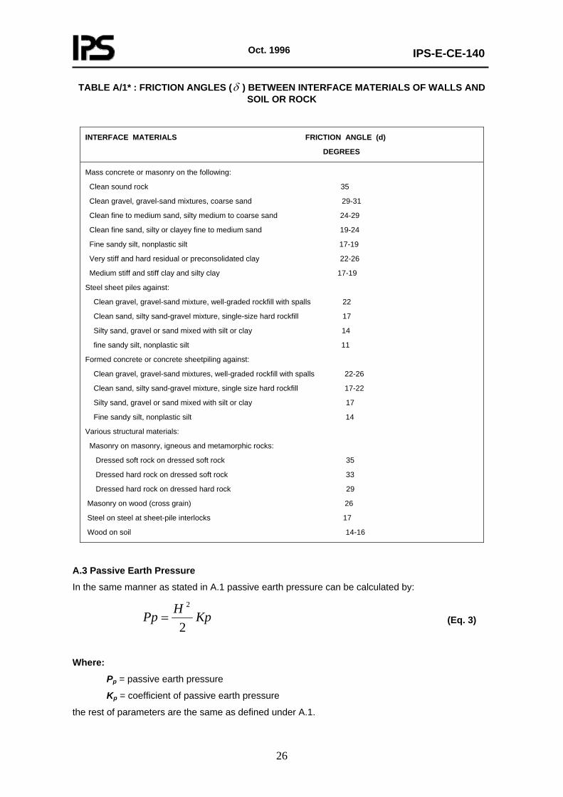
TABLE A/1* : FRICTION ANGLES (δ ) BETWEEN INTERFACE MATERIALS OF WALLS AND SOIL OR ROCK
INTERFACE MATERIALS FRICTION ANGLE (d)
DEGREES
Mass concrete or masonry on the following:
Clean sound rock 35
Clean gravel, gravel-sand mixtures, coarse sand 29-31
Clean fine to medium sand, silty medium to coarse sand 24-29
Clean fine sand, silty or clayey fine to medium sand 19-24
Fine sandy silt, nonplastic silt 17-19
Very stiff and hard residual or preconsolidated clay 22-26
Medium stiff and stiff clay and silty clay 17-19
Steel sheet piles against:
Clean gravel, gravel-sand mixture, well-graded rockfill with spalls 22
Clean sand, silty sand-gravel mixture, single-size hard rockfill 17
Silty sand, gravel or sand mixed with silt or clay 14
fine sandy silt, nonplastic silt 11
Formed concrete or concrete sheetpiling against:
Clean gravel, gravel-sand mixtures, well-graded rockfill with spalls 22-26
Clean sand, silty sand-gravel mixture, single size hard rockfill 17-22
Silty sand, gravel or sand mixed with silt or clay 17
Fine sandy silt, nonplastic silt 14
Various structural materials:
Masonry on masonry, igneous and metamorphic rocks:
Dressed soft rock on dressed soft rock 35
Dressed hard rock on dressed soft rock 33
Dressed hard rock on dressed hard rock 29
Masonry on wood (cross grain) 26
Steel on steel at sheet-pile interlocks 17
Wood on soil 14-16
A.3 Passive Earth Pressure
In the same manner as stated in A.1 passive earth pressure can be calculated by:
KpHPp2
2
= (Eq. 3)
Where:
Pp = passive earth pressure
Kp = coefficient of passive earth pressure
the rest of parameters are the same as defined under A.1.
Oct. 1996
IPS-E-CE-140
27
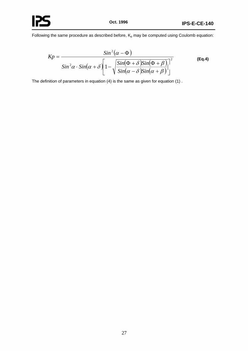
Following the same procedure as described before, Kp may be computed using Coulomb equation:
( )
( ) ( ) ( )( ) ( )
2
2
2
1 ⎥⎦
⎤⎢⎣
⎡
+−+Φ+Φ
−+⋅
Φ−=
βαδαβδδαα
α
SinSinSinSinSinSin
SinKp (Eq.4)
The definition of parameters in equation (4) is the same as given for equation (1) .