Embed Size (px)
Citation preview
ENGINEER MANUAL
ENGINEERING AND DESIGN
SANITARY LANDFILL
MOBILIZATION CONSTRUCTION
DEPARTMENT OF THE ARMYCORPS OF ENGINEERS
OFFICE OF THE CHIEF OF ENGINEERS
EM 1110-3-177April 1984 .
DEPARTMENT OF THE ARMYU.S . Army Corps of Engineers
DAEN-ECE-G
Washington, D .C . 20314
Engineer ManualNo . 1110-3-177
l .
Purpose .
This manual provides guidance for the construction and operationof sanitary landfills at U.S . Army mobilization facilities .
2 .
Applicability .
This manual is applicable to all field operatingactivities having mobilization construction responsibilities .
3 . Discussion . Criteria and standards presented herein apply to constructionconsidered crucial to a mobilization effort .
These requirements may bealtered when necessary to satisfy special conditions on the basis of goodengineering practice consistent with the nature of the construction .
Designand construction of mobilization facilities must be completed within 180 daysfrom the date notice to proceed is given with the projected life expectancy offive years . Hence, rapid construction of a facility should be reflected inits design .
Time-consuming methods and procedures, normally preferred overquicker methods for better quality, should be de-emphasized.
Lesser gradematerials should be substituted for higher grade materials when the lessergrade materials would provide satisfactory service and when use of highergrade materials would extend construction time .
Work items not immediatelynecessary for the adequate functioning of the facility should be deferreduntil such time as they can be completed without delaying the mobilizationeffort .
FOR THE COMMANDER :
Engineering and DesignSANITARY LANDFILL
Mobilization Construction
wrilooLlANAUGHCorps of Engineers
of Staff
EM 1110-3-177
9 April 1984
DEPARTMENT OF THE ARMY
EM 1110-3-177U . S . Army Corps of Engineers
Washington, D .C . 203.14
Engineer ManualNo . 1110-3-177 9 April 1984
Engineering and DesignSANITARY LANDFILL
Mobilization Construction
Paragraph Page '
CHAPTER 1 . GENERAL
Purpose and scope . . . . . . . . . . . . . . 1-1 1-1Regulatory requirements . . . . . . . . 1-2 1-1Health and safety objectives . . . 1-3 1-1Solid waste stabilization
in a sanitary landfill . . . . . . . 1-4 1-1
CHAPTER 2 . SITE SELECTION
General . . . . . . . . . . . . . . . . . . . . . . . . 2-1 2-1Selection factors . . . . . . . . . . . . . . 2-2 2-1
CHAPTER 3 . SANITARY LANDFILL DESIGN
General . . . . . . . . . . . . . . . . . . . . . . . . 3-1 3-1Data for sanitary landfillplanning . . . . . . . . . . . . . . . . . . . . . 3-2 3-1
Volume requirements . . . . . . . . . . . . 3-3 3-1Site improvements . . . . . . . . . . . . . . 3-4 3-3Control of surface water . . . . . . . 3-5 3-5Ground water protection . . . . . . . . 3-6 3-8Gas control . . . . . . . . . . . . . . . . . . . . 3-7 3-10Plans for design, construction,operations, and maintenanceof sites . . . . . . . . . . . . . . . . . . . . . 3-8 3-12
Cover material . . . . . . . . . . . . . . . . . 3-9 3-13
CHAPTER 4 . SANITARY LANDFILL OPERATIONS
General . . . . . . . . . . . . . . . . . . . . . . . . 4-1 4-1Criteria . . . . . . . . . . . . . . . . . . . . . . . 4-2 4-1Landfilling methods . . . . . . . . . . . . 4-3 4-2Equipment . . . . . . . . . . . . . . . . . . . . . . 4-4 4-6Effect of climate on sanitary
landfill . . . . . . . . . . . . . . . . . . . . . 4-5 4-9
APPENDIX A . REFERENCES A-1
EM 11,10-3-1779 Apr 84
LIST OF-FIGURES
Figure 3- 1 .
Yearly volume of compacted solid waste for afacility of 10,000 : persons .
3.-2 .
paily volume of compacted solid waste .3-3 .
Plan and section views of surface water .control .4-:1 .
Sanitary landfill construction .4-2 .
Trench method .4-3 .
Area method .4-4 .
Progressive s-lope thod .
CHAPTER 1
GENERAL
1-1 . Purpose and scope . This manual prescribes methods and guidancefor the construction and operation of sanitary landfills at Armymobilization facilities .
1-2 . Regulatory requirements . The minimum legal requirements for allSolid Waste Disposal facilities will be in accordance with PL 94-580and with 40 CFR 257 . The criteria presented herein represent minimumdesign criteria which will meet the legal requirements in most cases .In instances where the local conditions or guidelines (state and local,etc .) require the use of more stringent criteria than related herein,those criteria will apply .
1-3 . Health and safety objectives . Solid wastes ordinarily containmany contaminants which can produce serious health hazards ornuisances . The engineering design must result in a sanitary landfillwhich, when operated correctly, will preclude the following :
Pollution of surface and ground waters .
Air pollution by odor, dust, or smoke .
Infestation by rats, flies, or other vermin .
Other nuisance factors such as noise .
- Fires .
- Explosive hazard from migrating and/or collecting methanegenerated within the fill .
EM 1110-3-1779 Apr 84
1-4 . Solid waste stabilization in a sanitary landfill . Thedecomposition of organic material in a sanitary landfill is usuallyanaerobic, and the end products are primarily gases and moist humusmaterial . Typically the gases are methane and hydrogen (both of whichcan be explosive), carbon dioxide, nitrogen, and hydrogen sulfide . Therate of stabilization is difficult to predict and depends on manyfactors including climate, moisture of the refuse, and degree ofcompaction .
CHAPTER 2
SITE SELECTION
EM 1110-3-1779 Apr 84
2-1 : General . Selection of a site is the most critical step inestablishing a landfill disposal facility . For mobilization work theprimary consideration is to dispose of solid waste as quickly andsafely as possible . Therefore, concerns such as aesthetic,socio-economic, and ultimate use of the land factors will not beconsidered except where a direct effect on health-related factors willresult .
2-2 . Selection factors . Site selection for a sanitary landfill mustbe accomplished in consideration of the following :
a . Available land area . Based on the criteria presented herein,sufficient land must be available to service the 5-year design life ofthe mobilization facility . All zoning ordinances should be reviewedand cleared or changed to eliminate any legalities that could preventor indefinitely hold up the use of a particular parcel of land for asanitary landfill .
b . Haul distance . The landfill siting must be a balance betweenadequate distance from housing and work areas and economical hauldistance . The landfill should be sited at least 750 feet frominhabited buildings and preferably so that prevailing winds are awayfrom living areas . Adequate clearance from areas of brush and trees toprevent spread of possible fires should be provided .
c . Access to the site . Sites should be accessible to appropriatevehicles by all-weather roads leading from the public or mobilizationcamp road systems .
d . Vicinity of airports . Sites located in the vicinity ofairports, where birds attracted to the landfill disposal facility couldpose a hazard to aircraft, should be avoided .
e . Sites traversed by utilities . Sites traversed by pipes,conduits, or power lines should not be considered unless the relocationof the utility is feasible .
f . Soil and cover material . It is essential for satisfactoryoperation of the sanitary fill that soil conditions be suitable forpreventing ground water pollution, excavating and covering the fill,and vehicle access . A soil investigation is required to determine thesuitability of the area to receive the fill and the availability ofcover material . Factors to consider in evaluating the soil arediscussed below .
(1) Excavation . Generally cover material must be excavated, andthe excavation thus formed often can be filled with solid waste .

EM" '1110-3-177Q , Apr,84,
Whether the excavation is for cover material or for a trench, it isdesirable that the soil be readily excavated with the equipmentavailable at the installation .
Areas - with shallow rock, hardpan; orlarge boulders will normally not be acceptable'.
(2)
Cover.
Proper cover material must be' available to seal thefill against infiltration' and insure anaerobic conditions .- Anefficient seal will also control odors and prevent access to the : wasteby rodents and insects . Soil for cover material should not contain`appreciable quantities of organic material and should`-be relativelyfree of stones larger than about 6 , inches .
The soil must beeffectively compacted by equipment which is to be used in theoperation.
Soil with a relatively uniform particle size is not asreadily compacted as soil containing particles with°a- wide range ofsizes . Unless specially treated, pure sands, clays, or silts are notsuitable for covering a sanitary landfill . The soil should supporttruck traffic throughout the year . The soil should'be low in claycontent for ease of changing moisture content and to avoid surfacecracking . Generally a silty sand or clayey sand' is preferable, but anysoil which will form an effective seal is acceptable .
g . Topographic conditions . The local topography must be consideredbecause it will affect the type of landfill operation to be used, theequipment requirements, and the extent of work necessary to make thesite usable .
h . Surface-water hydrology . The existing natural drainage andrunoff characteristics of the area under investigation must beconsidered . Therefore, the local surface water hydrology of the areabecomes important . Other conditions of flooding must also beidentified . Landfill disposal facilities should be located where thepotential for surface drainage onto the landfill from adjacent land isminimal .
i . Geologic and hydrogeologic conditions . Geologic andhydrogeologic conditions are important parameters in establishing theenvironmental compatibility of the area for a landfill site . Althoughdifficult to ascertain at times, data on these factors are necessary toassess the pollution potential of the proposed site and to establishwhat must be done to the site to insure that the movement of leachateor gases from the landfill will not adversely affect the quality oflocal ground water or contaminate other subsurface or bedrock aquifers .Highly permeable formations such as sand, gravel, porous rock, karst,and fissured bedrock are undesirable subgrades for sanitary landfills .More impermeable soils such as clay would be desirable if the materialhas not nor will not experience drying and cracking . For thepreliminary assessment of sites, United States Geological Survey mapsand state or local geologic data may provide useful information . Logsof nearby wells should also be reviewed .
2-2

EM 1110- 3-1779 Apr 84
j . Environmentally sensitive areas . Environmentally sensitiveareas, including wetlands, 100-year floodplains, permafrost areas,critical habitats of endangered species, fault zones, and rechargezones of sole source aquifers should be avoided or receive lowestpriority as potential locations for landfill disposal facilities .
CHAPTER 3
SANITARY LANDFILL DESIGN
EM 1110-3-1779 Apr 84
3-1 . General . The designing of a sanitary landfill calls fordeveloping a detailed description and plans that outline the steps tobe taken to provide for the safe, efficient disposal of the quantitiesand types of solid wastes that are expected to be received . Thedesigner outlines volume requirements, site improvements (clearing ofthe land, construction of roadways and buildings, fencing, utilities),and all the equipment necessary for day-to-day operations of thespecific landfilling method involved . He also provides for controllingwater pollution and the movement of decomposition gas .
3-2 . Data for sanitary landfill planning .
a . Waste characteristics . The data on the solid waste for whichdisposal is required are : the types of waste, the amounts, and thevariations in delivery rates . When possible, the information should bebased on an analysis of solid wastes from the installation on which theproject is located, or from a similar installation . For newinstallations, an analysis can be made based on the population to beserved and other major sources of solid waste . The daily per capitaquantity of solid waste for mobilization facilities will be 3 to 4pounds of combined refuse and garbage . This rate is based on effectivepopulation which is the sum of the resident population plus one-thirdof the nonresident employees .
b . Operation equipment . Information on the equipment to be used,both for refuse delivery and sanitary landfill operation is required .This will include any planned changes in equipment . The capabilitiesof this equipment must be considered in evaluating factors such asaccess roads, grades, drainage, and operation in severe climates .
c . Operational methods . Methods of operating a landfill could havean effect on landfill design . Therefore, the desired method ofoperation should be reviewed before design commences .
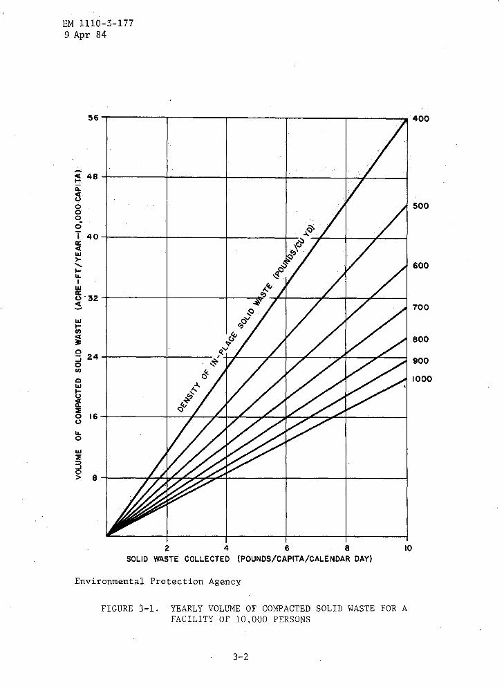
3-3 . Volume requirements . If the rate at which solid wastes arecollected and the capacity of the proposed site are known, its usefullife can be estimated .
a . Waste-to-cover ratio . The ratio of solid waste to covermaterial volume usually ranges between 4 :1 and 3 :1 ; it is, however,influenced by the thickness of the cover used and cell configuration .If cover material is not excavated from the fill site, this ratio maybe compared with the volume of compacted soil waste and the capacity ofa site determined from figure 3-1 . For example, a facility having a10,000 population and a per capita collection rate of 4 pounds per daymust dispose of, in 1 year, approximately 16 acre-feet of solid waste
EM 1110-3-1779 Apr 84
wHN3OJO
cwHQa0UOw
JO
56
;j.
48 -o.v000Oia
40 -i
24-
8 -
2
4
6
8SOLID WASTE COLLECTED (POUNDS/CAPITA/CALENDAR DAY)
Environmental Protection Agency
FIGURE 3-1 . YEARLY VOLUME OF COMPACTED SOLID WASTE FOR AFACILITY OF 10,000 PERSONS
3-2
10
400
500
600
700
800
900
1000
I
r
i
EM 1110-3-1779 Apr 84
if it is compacted to 600 pounds per cubic yard . If it were compactedto only 400 pounds per cubic yard, the volume disposed of in 1 yearwould occupy nearly 24 acre-feet . The volume of soil required for the600-pound density at a solid waste-to-cover ratio of 4 :1 would be 4 .0acre-feet ; the 400-pound density waste would need 6 .0 acre-feet . Adensity of 600 pounds per cubic yard will be used for mobilizationdesign and operation .
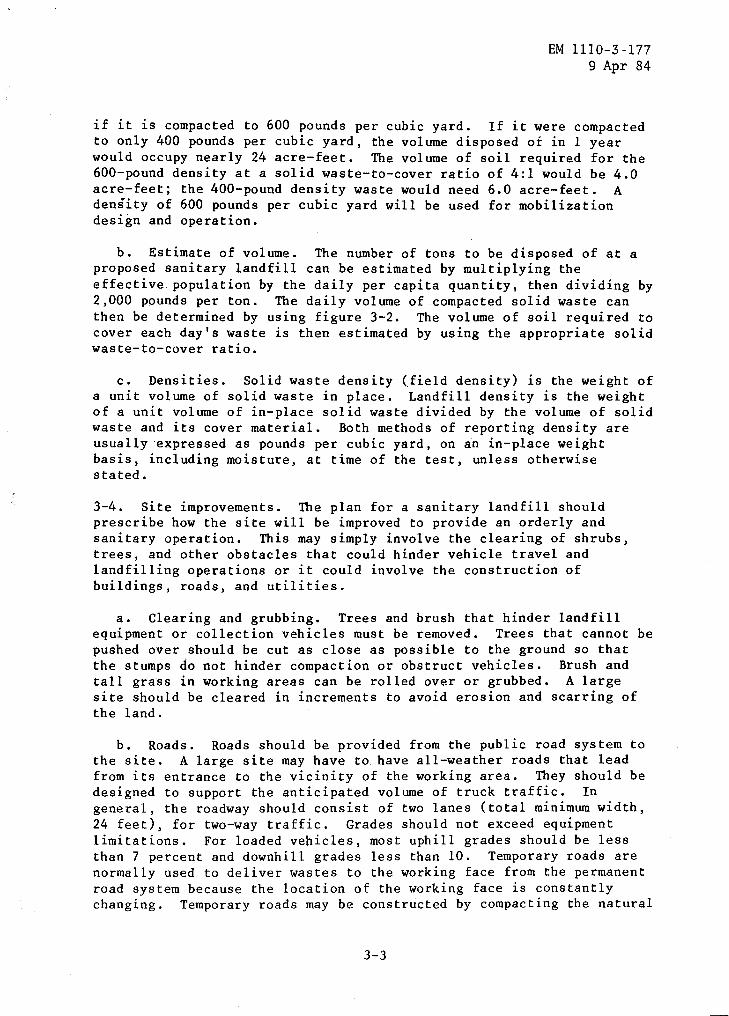
b . Estimate of volume . The number of tons to be disposed of at aproposed sanitary landfill can be estimated by multiplying theeffective population by the daily per capita quantity, then dividing by2,000 pounds per ton . The daily volume of .compacted solid waste canthen be determined by using figure 3-2 . The volume of soil required tocover each day's waste is then estimated by using the appropriate solidwaste-to-cover ratio .
c . Densities . Solid waste density (field density) is the weight ofa unit volume of solid waste in place . Landfill density is the weightof a unit volume of in-place solid waste divided by the volume of solidwaste and its cover material . Both methods of reporting density areusually expressed as pounds per cubic yard, on an in-place weightbasis, including moisture, at time of the test, unless otherwisestated .
3-4 . Site improvements . The plan for a sanitary landfill shouldprescribe how the site will be improved to provide an orderly andsanitary operation . This may simply involve the clearing of shrubs,trees, and other obstacles that could hinder vehicle travel andlandfilling operations or it could involve the construction ofbuildings, roads, and utilities .
a . Clearing and grubbing . Trees and brush that hinder landfillequipment or collection vehicles must be removed . Trees that cannot bepushed over should be cut as close as possible to the ground so thatthe stumps do not hinder compaction or obstruct vehicles . Brush andtall grass in working areas can be rolled over or grubbed . A largesite should be cleared in increments to avoid erosion and scarring ofthe land .
b . Roads . Roads should be provided from the public road system tothe site . A large site may have to have all-weather roads that leadfrom its entrance to the vicinity of the working area . They should bedesigned to support the anticipated volume of truck traffic . Ingeneral, the roadway should consist of two lanes (total minimum width,24 feet), for two-way traffic . Grades should not exceed equipmentlimitations . For loaded vehicles, most uphill grades should be lessthan 7 percent and downhill grades less than 10 . Temporary roads arenormally used to deliver wastes to the working face from the permanentroad system because the location of the working face is constantlychanging . Temporary roads may be constructed by compacting the natural
3-3
EM 1110-3-1779 Apr 84
Environmental Protection Agency
40 80 120 160SOLID WASTE DISPOSED DAILY (TONS/DAY)
FIGURE 3-2 . DAILY VOLUME OF COMPACTED SOLID WASTE
200
1000 400
Q0
800- 500
W
3 6000
600JON 700OWHV 800a
900400-
1000OWJO 200-
EM 1110-3-177g Apr 84
soil present and by controlling drainage or by topping them with alayer of a tractive material, such as gravel, crushed stone, cinders,broken concrete, mortar, or bricks . Lime, cement, or asphalt bindersmay make such roads more serviceable . If fewer than 25 round trips perday to the landfill are expected, a graded and compacted soil willusually suffice . More than 50 round trips per day generally justifiesthe use of calcium chloride as a dust inhibitor or such bindermaterials as soil cement or asphalt .
A base course plus a binder isdesirable if more than 100 to 150 round trips per day are anticipated .
c . Buildings . A building or construction-type field trailer shouldbe provided for office space and employee facilities . Since a landfilloperates in wet and cold weather, some protection from the elementsshould be provided . Operational records may also be kept at the site .Sanitary facilities should be provided for both landfill and collectionpersonnel . Buildings should be temporary types and, preferably, bemovable . The design and location of all structures should consider gasmovement and differential settlement caused by the decomposing solidwaste .
d . Utilities . All sanitary landfill sites should have electrical,water, and sanitary services . Remote sites may have to extend existingservices or use acceptable substitutes . Portable chemical toilets canbe used to avoid the high cost of extending sewer lines ; potable watermay be trucked in, and an electric generator may be used instead ofhaving power lines run into the site . Water should be available fordrinking, fire fighting, dust control, and employee sanitation . Asewer line may be called for, especially at large sites and those whereleachate is collected and treated with domestic wastewater . Telephoneor radio communications are also desirable .
e . Fencing . Peripheral and litter fences are commonly needed atsanitary landfills . The first type is-used to control or limit. access,keep out children and animals, screen the landfill, and delineate theproperty line . If vandalism and trespassing are to be discouraged, a6-foot high fence topped with three strands of barbed wire projectingat a 45 degree angle is desirable .
A wooden fence or a hedge may beused to screen the operation from view . Litter fences are used tocontrol blowing paper in the immediate vicinity of the working face .As a general rule, trench operations require less litter fencingbecause the solid waste tends to be confined within the walls of thetrench . At a very windy trench site, a 4-foot snow fence will usuallysuffice . Blowing paper is more of a problem in an area operation ; 6-to10-foot litter fences are often needed . Since the location of theworking face shifts frequently, litter fences should be movable .
3-5 . Control of surface water . Control of surface water runoff at alandfill disposal facility is necessary in order to minimize thepotential for environmental damage to ground and surface waters bydirect and indirect effects . Direct surface water contamination can
3-5
Err 1110-3-1779 Apr 84
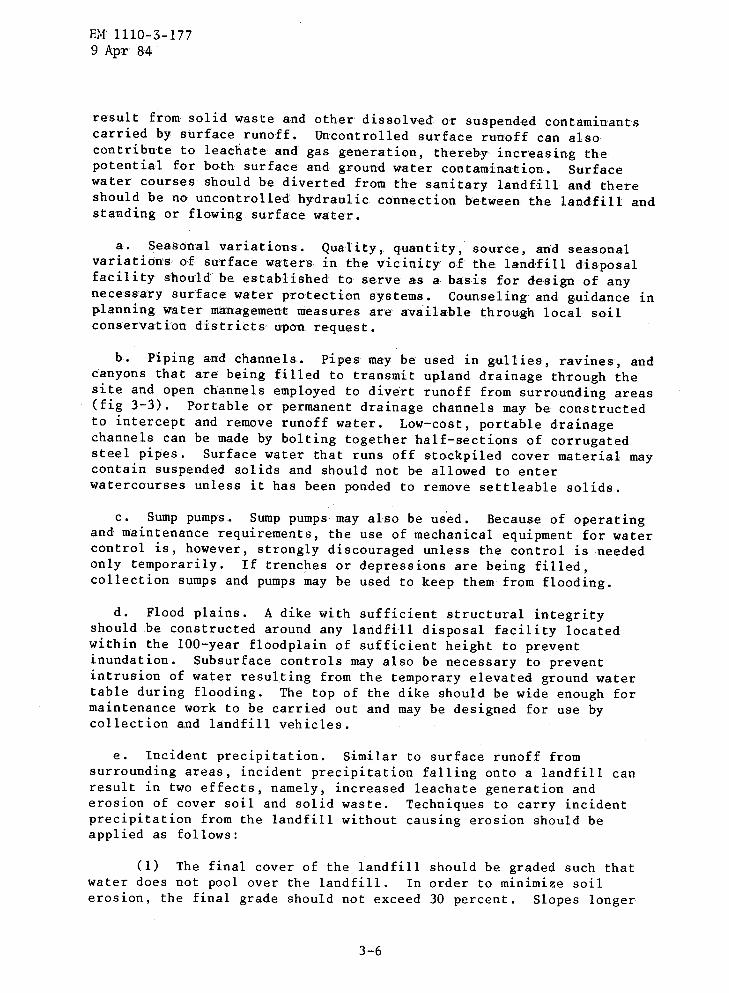
result from solid waste and other dissolved or suspended contaminantscarried by surface runoff . Uncontrolled surface runoff can alsocontribute to leachate' and gas generation, thereby increasing thepotential for both surface - and ground water contamination .
Surfacewater courses should be diverted from' the sanitary landfill and thereshould be no uncontrolled hydraulic connection between the landfill andstanding or flowing surface water .
a . Seasonal variations- . Quality, quantity, source, and' seasonalvariations of surface waters in the vicinity, of the landfill disposalfacility should` be established to serve- a-s a basis for design of anynecessary surface water protection systems . Counseling and guidance inplanning water management measures are available through local soilconservation districts- upon request .
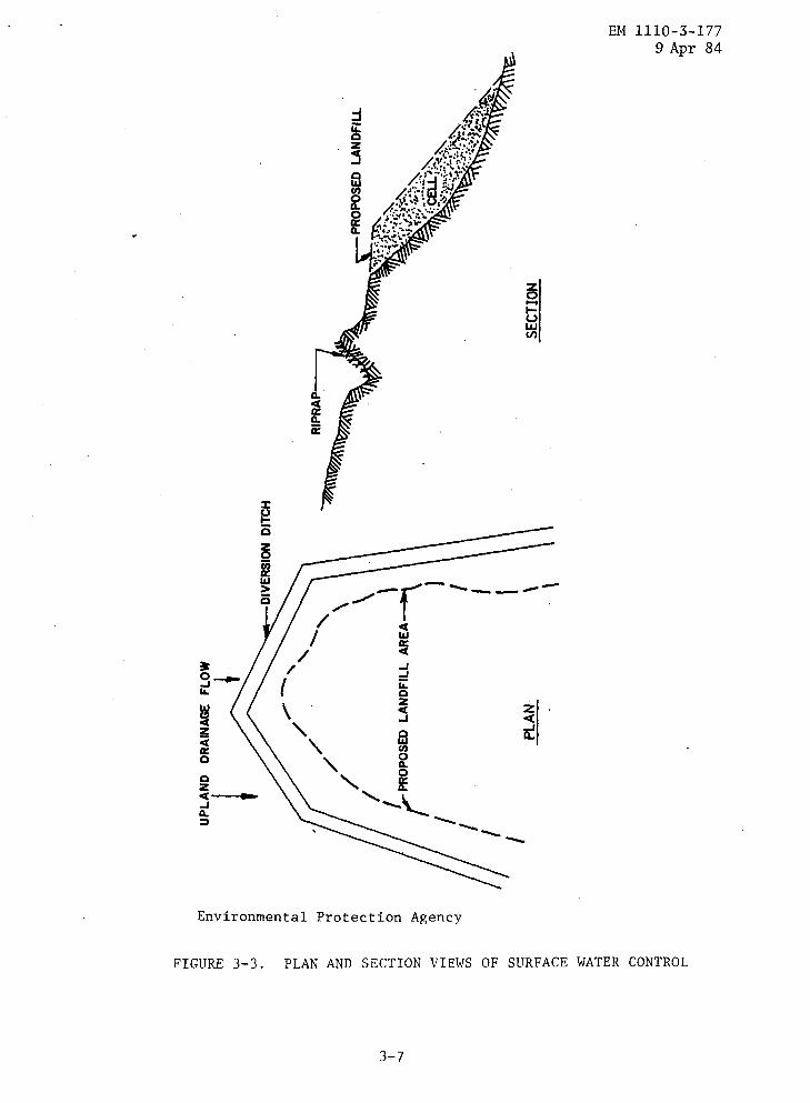
b . Piping and channels . Pipes may be used in gullies, ravines, andcanyons that are being filled to transmit upland drainage through thesite and open channels employed to divert runoff from surrounding areas(fig 3-3) . Portable or permanent drainage channels may be constructedto intercept and remove runoff water . Low-cost, portable drainagechannels can be made by bolting together half-sections of corrugatedsteel pipes . Surface water that runs off stockpiled cover material maycontain suspended solids and should not be allowed to enterwatercourses unless it has been ponded to remove settleable solids .
c . Sump pumps . Sump pumps may also be used . Because of operatingand maintenance requirements, the use of mechanical equipment for watercontrol is, however, strongly discouraged unless the control is neededonly temporarily . If trenches or depressions are being filled,collection sumps and pumps may be used to keep them from flooding .
d . Flood plains . A dike with sufficient structural integrityshould be constructed around any landfill disposal facility locatedwithin the 100-year floodplain of sufficient height to preventinundation . Subsurface controls may also be necessary to preventintrusion of water resulting from the temporary elevated ground watertable during flooding . The top of the dike should be wide enough formaintenance work to be carried out and may be designed for use bycollection and landfill vehicles .
e . Incident precipitation . Similar to surface runoff fromsurrounding areas, incident precipitation falling onto a landfill canresult in two effects, namely, increased leachate generation anderosion of cover soil and solid waste . Techniques to carry incidentprecipitation from the landfill without causing erosion should beapplied as follows :
(1) The final cover of the landfill should be graded such thatwater does not pool over the landfill . In order to minimize soilerosion, the final grade should not exceed 30 percent . Slopes longer
3-6
Environmental Protection Agency
FIGURE 3-3 . PLAN AND SECTION VIEWS OF SURFACE WATER CONTROL
3-7
EM 1110-3-1779 Apr 84
EM 1110-3-1779 Apr 84
than 25 feet may require additional erosion control measures, such asconstruction of horizontal terraces, of sufficient width for equipmentoperation, for every 20 feet rise in elevation . Minimum slope,including terraces, should be .2 percent .
(2) The final soil cover on a completed landfill disposalfacility should be seeded or otherwise vegetated to minimize erosionand maximize evapotranspiration .
(3) If landfill site design incorporates minimization ofleachate generation, a low permeability cover soil with a low swell andshrink tendency upon wetting and drying should be utilized to avoidcracking .
3-6 . Ground water protection .
a . Ground water uses . Current and projected use of ground waterresources in the vicinity of the landfill disposal facility should bedetermined as a basis for design of any necessary ground waterprotection system as follows :
(1) Establish initial (background) quality of water resources inthe potential zone of influence . If ground water analyses determinethat the total dissolved solids (TDS) content of the water is greaterthan 10,000 mg/l, then it shall be termed unusable and no protection ofthe ground water will be required .
(2) Establish the depth to the water table and the direction andrate of ground water flow with consideration of withdrawal rates byground water users .
(3) Establish potential interactions of the landfill disposalfacility, its hydrogeology, and the real ground and surface waters,based upon'historical records and other sources of information .
b . Leachate control measures . Landfill leachate generation cannotbe avoided except in some arid climates ; therefore, leachate controlmeasures for water quality protection should be incorporated in thesite design when the ground water has been determined to be usable .Leachate control, when necessary with site design, should beaccomplished through application of one or more of the followingpractices :
(1) Unless underlying ground water is determined to be unusableas a drinking water or other supply source and therefore not in need ofprotection, the bottom of a landfill disposal facility should besubstantially (5 feet or more) above the seasonal high ground watertable, to prevent direct contact of disposed solid waste and the groundwater .
function
(2) A liner may be employed to control the movement of fluids,this capacity .i s a function
and the depth (or head) ofof flow increases with
and many types of material can function successfully inThe rate of passage of leachate through liner materialsof the measured permeability of the materialleachate on the liner . In general, the ratedepth of leachate .
(a) The variety of liner materialsnaturally occurring materials such as clays, amended natural materialssuch as soil cements, and artificial materials such as asphalticmaterials and polymeric membranes .
available include
(b) Liner materials which are to significantly restrictflow of leachate from the bottom of the landfill should have thefollowing properties .
Permeability of 1 X 10⁻⁷ cm/second (about 0 .1 foot/year) orless .
Ability to resist physical and chemical attack by leachate .
Capability of maintaining integrity for the
The practical minimum thickness for naturalinches .
3-9
design life .
soil liners is
EM 1110-3-1779 Apr 84
12
- The practical minimum thickness for synthetic membrane liners is20 mils .
(c) Artificial liner material, if selected, should be placedupon a carefully prepared base of selected material which will preventliner puncture while providing uniform support and should be coveredwith suitable material that will further protect the liner from damageand provide a drainage blanket for the leachate collection system.Approximately 2 feet of material is effective in protecting a linerfrom mechanical damage (puncture) . The lowest 6 inches of materialshould be highly permeable to allow the leachate collection system
properly .
liner should be
the
(d) Removal of leachate collected on aincorporated into the design of a lined landfill to avoid surfaceseepage and relieve hydraulic pressure on the liner . To facilitateleachate removal, liner materials should be sloped to one or morepoints and covered with a layer of highly permeable material such aspea gravel . A grade of 1 percent or more should be utilized .
to
(e) Once collected, landfill leachate should be disposed tothe land or surface water in an environmentally sound manner to protectsurface and ground water quality . (Public Law 92-500 requires a permitfor the discharge of collected leachate to surface water .)
EM 1110-3-1779 Apr 84
- Leachate treatment and disposal should consist, as a minimum,of a lined waste stabilization pond with controlled discharge .
Raw or treated landfill leachate should be discharged into amunicipal or industrial wastewater treatment system only ifthis discharge will not impede the operation of the wastewatertreatment system . Limited experience has shown that when rawmunicipal solid waste leachate volume exceeds about 5 percentof the total wastewater treatment plant flow, interruption ofbiological treatment processes may occur .
Raw or treated leachate can be disposed by controlledapplication onto the surface of the land provided sufficientacreage is available and hydrology, soil type, vegetation,topography, and climate for leachate disposal have beenconsidered, and surface or ground water contamination will notoccur .
Recirculation of collected landfill leachate onto active orcompleted sections of the landfill can reduce leachateconstituent concentrations by chemical and biologicalprocesses and may be effective in reducing leachate volume .This technique can result in, at least, partial stabilizationof young (0 to 5 years) landfill leachates which arerelatively concentrated . in comparison with rather oldstabilized landfill leachates .
3-7 . Gas control . Control of gases from a landfill disposal facilitymay be accomplished by techniques which : minimize the production ofdecomposition gases or occurrence of other harmful gases, control theescape of gases into the atmosphere, and minimize the migration ofgases into soils surrounding the site . Gas control should beaccomplished in accordance with the following :
a . Minimize infiltration . Leachate and runoff control measureswhich are intended to minimize the infiltration of water into a solidwaste landfill may also reduce gas generation, primarily CH4 and C02resulting from decomposition of disposed organic solid waste .
b . Prohibit volatile substances . Volatile solid waste materials orwastes with a known high potential for release of harmful gases as aresult of chemical reaction should not be accepted for disposal at alandfill disposal facility where such gases are normally required to beminimized or - avoided .
c . Encapsulate the solid waste . Encapsulation of solid waste in alandfill (e .g ., low permeability liner and final cover) to prevent orminimize infiltrating water should be coupled with an effective
ventilation system to remove decomposition gas from the landfill, asnecessary .
EM 1110-3-1779 Apr 84
d . Allow vertical migration of gases . If a relatively porousmaterial is used for cover at a landfill, which does not impedeinfiltrating water, gases should migrate vertically out of the landfillsurface, except when frozen or saturated, for dissipation into theatmosphere . However, deep landfills may experience gas pressurebuildup, regardless of cover used .
e . Review surrounding land area . Since horizontal migration ofgases from landfills (due to both diffusion and pressure gradients)through surrounding soils is common, a review of the land areasurrounding the landfill proper should be performed . For shallowlandfills, a "rule of thumb" for estimating potential gas migration isa distance equal to 10 times the maximum depth of the landfill beloworiginal grade . If nearby underground utilities exist, additionalreviews along the utility corridor should be performed .
f . Passive barriers . Passive barriers which may be considered forthe prevention of horizontal migration of gases include :
(1) Cutoff walls constructed of naturally occurring materials,such as compacted moist clays, .or artificial materials, such asasphaltic or polymeric materials .
(a) To assure effectiveness, the cutoff wall should extendfrom the ground surface down to a gas impervious layer (e .g ., bedrockor ground water) below the bottom of the landfill .
(b) Even though polymeric materials may be virtuallyimpermeable to water, they should be evaluated for permeability togases .
(c) Even when compacted, clays and other soils are impermeableto gases only when water saturated .
(2) Venting systems, installed either on or off the landfillproper, consist of either gravel-filled trenches, perforated pipes, orboth .
(a) Perforated pipes have been shown to be of limitedeffectiveness except in the immediate vicinity of the pipe and aretherefore not recommended for reduction of pressure in a landfill, whenused alone .
(b) Gravel-filled trenches, while generally more effective ,than perforated pipes, still permit some migration of gases across thetrench, especially when covered by snow or ice .
3-11
EM 1110-3-1779 Apr 84
(c) Gravel-filled trenches equipped with vertical perforatedpipes have been shown to reduce the effect of temporary covers such asice or snow but remain of limited effectiveness in landfill gasmigration control .
(d) Gravel-filled trenches must usually be equipped forremoval of water or leachate from the trench bottom and are susceptibleto plugging by biomass buildup .
(3) Combination passive barriers installed off the landfill,which consist of gravel-filled trenches in. combination with animpermeable barrier installed on'the side of the trench opposite thelandfill, provide good protection against horizontal gas migration whenkeyed to a gas impermeable strata below the landfill .
3-8 . Plans for design, construction, operations, and maintenance ofsites . Plans for design, construction, operations, and maintenance ofsites should include :
a . Evidence . Evidence of compliance with applicable state andFederal regulations .
b . Detailing . Careful detailing of all design and operationalconsiderations necessary to bring site conditions to an acceptablelevel .
c . Presentation and discussion . A clear presentation and discussionof any separate areas which have been incorporated into the landfilldesign for disposal of specific wastes requiring special or separatehandling .
d . Other . Other pertinent information, such as :
(1) Initial and final topographies at contour intervals of 5 feetor less as specified by the state and local regulatory authorities .
(2) Land use and zoning within, at least, one-quarter mile of thesite showing the location of all private wells, water courses, rockoutcroppings, roads, and buildings .
site .
(3) Location of all airports within 2 miles of the site .
(4) Location of all utilities within, at least, 500 feet of the
(5) Temporary and permanent all-weather access roads .
(6) Screening and other nuisance control measures .
(7) Narrative descriptions, with associated technical drawings,indicating site development and operation procedures .
(8) Contingency plans .
3-9 . *Cover material . The cover material selected should provide for abalance among the major functions of :
- Vehicle traffic .
-
Water infiltration control .
-
Gas migration control .
-
Fire resistance .
-
Erosion control .
-
Vector control .
-
Support of vegetation .
EM 1110-3-1779 Apr 84
CHAPTER 4
SANITARY LANDFILL OPERATIONS
EM 1110-3-1779 Apr 84
4-1 . General . Proper site selection and design alone are insufficientto result in a landfill which provides for the protection of publichealth and the environment . To achieve such protection, operation of alandfill should be based upon these guidelines or other equivalentpractices .
4-2 . Criteria . A facility for the landfill disposal of solid wasteshould be operated in accordance with the following :
a . Acceptable wastes . In general, only wastes for which thefacility has been specifically designed should be accepted fordisposal ; however, other wastes may be accepted if it has beendemonstrated to the responsible agency that they can be satisfactorilydisposed within the design capability or after appropriate facilitymodifications .
(1) Specific wastes, whose chemical, biological or physicalcharacteristics are not compatible with disposal site design, location,or operation and which could pose an unacceptable environmental orhealth effect or pose a threat to the safety of personnel or users ofthe facility, should be prohibited from acceptance for disposal .
(2) PL 94-580 restricts the acceptance of any hazardous waste tolandfills which were not specifically designed for that waste .Designer should note which of these wastes may be handled at eachfacility, and operating personnel should be made aware of anyrestrictions .
b . Cover material . Cover material should be applied, as necessary,to minimize fire hazards, odors, blowing litter, vector food andharborage ; control gas venting and infiltration of precipitation ;discourage scavenging ; and provide an aesthetic appearance .
(1) A minimum of 6 inches of soil cover material should beapplied daily .
(2) Cells which will not have additional wastes placed on themfor 3 months or more should be covered with 12 inches of covermaterial .
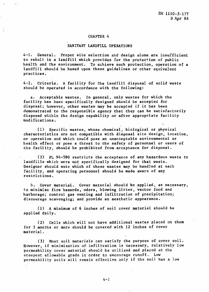
(3) Most soil materials can satisfy the purpose of cover soil .However, if minimization of infiltration is necessary, relatively lowpermeability cover material should be utilized and placed at thesteepest allowable grade in order to encourage runoff . Lowpermeability soils will remain effective only if the soil has a low
EM 1110-3-1779 Apr 84
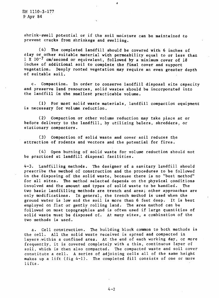
shrink-swell potential or if the soil moisture can be maintained toprevent cracks from shrinkage and swelling .
(4) The completed landfill should be covered with 6 inches ofclay or other suitable material with permeability equal to or less than1 X 10-7 cm/second or equivalent, followed by a minimum cover of 18inches of additional soil to complete the final cover and supportvegetation . Deeply rooted vegetation may require an even greater depthof suitable soil .
c . Compaction . In order to conserve landfill disposal site capacityand preserve land resources, solid wastes should be incorporated intothe landfill in the smallest practicable volume .
(1) For most solid waste materials, landfill compaction equipmentis necessary for volume reduction .
(2) Compaction or other volume reduction may take place at orbefore delivery to the landfill, by utilizing balers, shredders, orstationary compactors .
(3) Compaction of solid waste and cover soil reduces theattraction of rodents and vectors and the potential for fires .
(4) Open burning of solid waste for volume reduction should notbe practiced at landfill disposal facilities .
4-3 . Landfilling methods . The designer of a sanitary landfill shouldprescribe the method of construction and the procedures to be followedin the disposing of the solid waste, because there is no "best method"for all sites . The method selected depends on the physical conditionsinvolved and the amount and types of solid waste to be handled . Thetwo basic landfilling methods are trench and area ; other approaches areonly modifications . In general, the trench method is used when theground water is low and the soil is more than 6 feet deep . It is bestemployed on flat or gently rolling land . The area method can befollowed on most topographies and is often used if large quantities ofsolid waste must be disposed of . At many sites, a combination of thetwo methods is used .
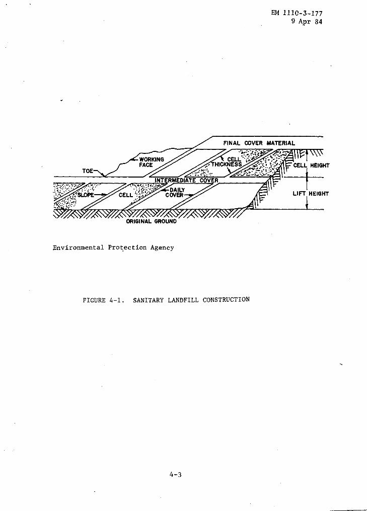
a . Cell construction . The building block common to both methods isthe cell . All the solid waste received is spread and compacted inlayers .within a confined area . At the end of each working day, or morefrequently, it is covered completely with a thin, continuous layer ofsoil, which is then also compacted . The compacted waste and soil coverconstitute a cell . A series of adjoining cells all of the same heightmakes up a lift (fig 4-1) . The completed fill consists of one or morelifts .
Environmental Protection Agency
FIGURE 4-1 . SANITARY LANDFILL CONSTRUCTION
EM 1110-3-1779 Apr 84
EM 1110-3-1779 Apr 84
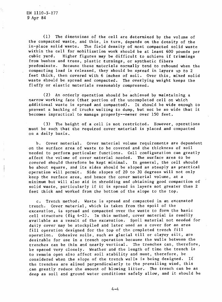
(1) The dimensions of the cell are determined by the volume ofthe compacted waste, and this, in turn, depends on the density of thein-place solid waste . The field density of most compacted solid wastewithin the cell for mobilization work should be at least 600 pounds percubic yard .
Higher figures may be difficult to achieve if trimmingsfrom bushes and trees, plastic turnings, or synthetic fiberspredominate . Because these materials normally tend to rebound when thecompacting load is released, they should be spread in layers up to 2feet thick, then covered with 6 inches of soil . Over this, mixed solidwaste should be spread and compacted . The overlying weight keeps thefluffy or elastic materials reasonably compressed .
(2) An orderly operation should be achieved by maintaining anarrow working face (that portion of the uncompleted cell on whichadditional waste is spread and compacted) . It should be wide enough toprevent a backlog of trucks waiting to dump, but not be so wide that itbecomes impractical to manage properly--never over 150 feet .
(3) The height of a cell is not restricted . However, operationsmust be such that the required cover material is placed and compactedon a daily basis .
b . Cover material . Cover material volume requirements are dependenton the surface area of waste to be covered and the thickness of soilneeded to perform particular functions . Cell configuration can greatlyaffect the volume of cover material needed . The surface area to becovered should therefore be kept minimal . In general, the cell shouldbe about square, and its sides should be sloped as steeply as practicaloperation will permit . Side slopes of 20 to 30 degrees will not onlykeep the surface area, and hence the cover material volume, at aminimum but will also aid in shredding and obtaining good compactinn ofsolid waste, particularly if it is spread in layers not greater than 2feet thick and worked from the bottom of the slope to the top .
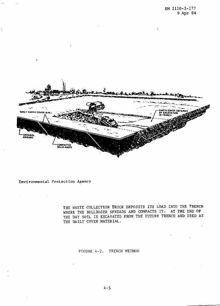
c . Trench method . Waste is spread and compacted in an excavatedtrench . Cover material, which is taken from the spoil of theexcavation, is spread and compacted over the waste to form the basiccell structure (fig 4-2) . In this method, cover material is readilyavailable as a result of the excavation . Spoil material not needed fordaily cover may be stockpiled and later used as a cover for an areafill operation designed for the top of the completed trench filloperation . Cohesive soils, such as glacial till or clayey silt, aredesirable for use in a trench operation because the walls between thetrenches can be thin and nearly vertical . The trenches can, therefore,be spaced very closely . Weather and the length of time the trench isto remain open also affect soil stability and must, therefore, beconsidered when the slope of the trench walls is being designed . Ifthe trenches are alined perpendicularly to the prevailing wind, thiscan greatly reduce the amount of blowing litter . The trench can be asdeep as soil and ground water conditions safely allow, and it should be
4-4
Environmental Protection Agency
THE WASTE COLLECTION TRUCK DEPOSITS ITS LOAD INTO THE TRENCHWHERE THE BULLDOZER SPREADS AND COMPACTS IT . AT THE END OFTHE DAY SOIL IS EXCAVATED FROM THE FUTURE TRENCH AND USED ASTHE DAILY COVER MATERIAL .
FIGURE 4-2 . TRENCH METHOD
EM 1110-3-1779 Apr 84
EARTH COVER OBTAINEDBY EXCAVATIONIN TRENCH
EM 1110-3-1779 Apr 84
at least twice as wide as any compacting equipment that will work init . The equipment at the site may excavate the trench continuously ata rate geared to landfilling requirements . At small sites, excavationmay be done on a contract basis .
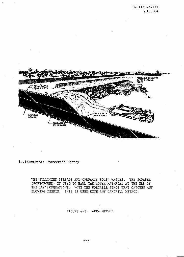
d . Area method . In this method, the waste is spread and compactedon the natural surface of the ground, and cover material is spread andcompacted over it (fig 4-3) . The area method is used on flat or gentlysloping land and also in quarries, strip mines, ravines, valleys, orother land depressions .
e . Combination methods . A sanitary landfill does not need to beoperated by using only the area or trench method . Combinations of thetwo are possible, and flexibility is, therefore, one of sanitarylandfilling's greatest assets . The methods used can be variedaccording to the constraints of a particular site .
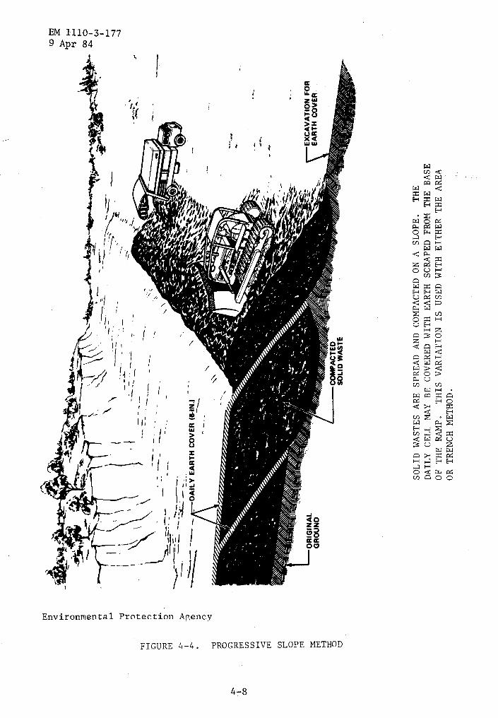
(1) One common variation is the progressive slope or ramp method,in which the solid waste is spread and,compacted on a slope . Covermaterial is obtained directly in front of the working face andcompacted on the waste (fig 4-4) . In this way, a small excavation ismade for a portion of the next day's waste . This technique allows formore efficient use of the disposal site when a single lift isconstructed than the area method does, because cover does not have tobe imported, and a portion of the waste is deposited below the originalsurface .
(2) Both methods might have to be used at the same site if anextremely large amount of solid waste must be disposed of . Forexample, at a site with a thick soil zone over much of it but with onlya shallow soil over the remainder, the designer would use the trenchmethod in the thick soil zone and use the extra spoil material obtainedto carry out the area method over the rest of the site . When a sitehas been developed by either method, additional lifts can beconstructed using the area method by having cover material hauled in .The final surface of the completed landfill should be so designed thatponding of precipitation does not occur . Settlement must, therefore,be considered . Grading of the final surface should induce drainage butnot be so extreme that the cover material is eroded. Side slopes ofthe completed surface should be 3 to 1 or flatter to minimizemaintenance .
4-4 . Equipment . The size, the type, and the amount of equipmentrequired at a sanitary landfill depend on the size and method ofoperation and to some degree on the experience and preference of thedesigner and equipment operators .
Environmental Protection Agency
FIGURE 4-3 . AREA METHOD
EM 1110-3-1779 Apr 84
PORTABLE FENCE TO-CATCH BLOWINGPAPER
THE BULLDOZER SPREADS AND COMPACTS SOLID WASTES . THE SCRAPER(FOREGROUND) IS USED TO HAUL THE COVER MATERIAL AT THE END OFTHE DAY'S OPERATIONS .
NOTE THE PORTABLE FENCE THAT CATCHES ANYBLOWING DEBRIS . THIS IS USED WITH ANY LANDFILL METHOD .
w 0 z H C r 0 b ra tTj H x 0 d
c N. n 0 c0 rt w H b 0
GROUND
SOLI
DWASTES
ARE
SPREAD
AND
COMPACTED
ONA
SLOPE
.TH
EDA
ILY
CELL
MAY
BECO
VERE
DWITH
EART
HSCRAPED
FROM
THE
BASE
OFTHE
RAMP
.THIS
VARIATION
ISUSED
WITH
EITH
ERTH
EAREA
ORTRENCH
METHOD
.
ORIG
INAL
r-EXCAVATIONFOR
EART
HCO
VER
3~v
a000 w F+
41-
1 V V
EM 1110-3-1779 Apr 84
a . Types . The most common equipment used on sanitary landfills isthe crawler or rubber-tired tractor . The tractor can be used with adozer blade, trash blade, or a front-end loader . A tractor isversatile and can normally perform all the operations : spreading,compacting, covering, trenching, and even hauling the cover material .The decision on whether to select a rubber-tired or a crawler-typetractor and a dozer blade, trash blade, or front-end loader must bebased on the conditions at each individual site and the equipment'savailability . Other equipment used at sanitary landfills are scrapers,compactors, draglines, and graders . This type of equipment is normallyfound only at large sanitary landfills where specialized equipmentincreases the overall efficiency .
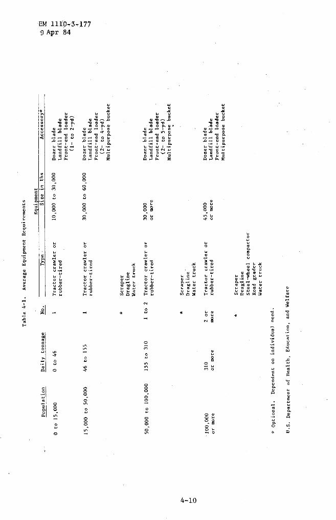
b . Size . The size of the equipment is dependent primarily onthe size of the operation . Small sanitary landfills for camps of15,000 or fewer, or sanitary landfills handling 46 tons of solidwastes per day or less, can operate successfully with one tractorof the 5- to 15-ton range . Heavier equipment in the 15- to 30-tonrange or larger can handle more waste and achieve bettercompaction . Heavy equipment is recommended for sanitary landfill sitesserving more than 15,000 people or handling more than 46 tons per day .
c . Amount . Sanitary landfills servicing 50,000 people or fewer, orhandling about 155 tons of solid wastes per day or less, normally canmanage well with one piece of equipment, but provisions must be madefor standby equipment . It is preferable that a second piece ofequipment be used for replacement during breakdown and routinemaintenance periods of the regular equipment . At large sanitarylandfills serving more than 100,000 persons, or handling more than 310tons of solid wastes per day, more than one piece of equipment will berequired . At these sites, specialized equipment can be utilized toincrease efficiency and minimize costs . In table 4-1, a general guideis given for the selection of the type, size, and amount of equipmentfor various sizes of sanitary landfills .
4-5 . Effect of climate on sanitary landfill . Adverse climate canseverely limit the capability of the sanitary landfill, but this can bepartially overcome by preplanning and operational techniques .
a . Cold weather . Extremely cold weather can greatly reduce thebiological activity in a sanitary landfill . In some regions wherewinter temperatures are less than minus 30 degrees F ., only minimalwaste stabilization occurs . A serious problem in cold regions isfrozen soil . This can be overcome to some extent by excavating for thefill during the summer season and stockpiling cover material .
b . Wet weather . The major problem in wet weather is maintainingmaneuverability of the refuse delivery vehicles and equipment . Thiscan be provided in the design by selecting a site that is well drained
4-9
Mult
ipur
pose
buck
et
*Optional
.Dependent
onindividual
need
.
*Sc
rape
rDragline
Watertruck
U.S
.Department
ofHe
alth
,Education,
and
Welf
are
*Sc
rape
rDragline
Steel-wheel
compactor
Road
grad
erWatertruck
Table
Popu
lati
onDaily
tonn
age
4-1.
Aver
age
Equipment
No.
Type
.-
Requ
irem
ents
Equipment
Size
inlb
s--
Acce
ssor
y*cD 9M
0to
15,000
0to
461
Trac
tor
craw
ler
or10
,000
to30
,000
Doze
rblade
rubb
er-t
ired
Landfill
blad
ew
Front-end
load
er00a
(1-to
2-yd
)
15,000
to50
,000
46to
155
1Tr
acto
rcr
awle
ror
30,0
00to
60,0
00Do
zerblade
rubb
er-t
ired
Landfill
blade
Front-end
load
er(2-
to4-yd)
50,000
to10
0,00
0155
to310
1to
2Tr
acto
rcr
awle
ror
rubb
er-t
ired
30,0
00or
more
Doze
rblade
Landfill
blad
eFront-end
load
er(2
-to
5-yd)
Mult
ipur
pose
buck
et
*Scraper
Dragline'
Water
truck
100,
000
310
2or
Trac
tor
craw
ler
or45
,000
Doze
rbl
ade
ormore
ormore
more
rubb
er-t
ired
ormore
Landfill
blad
eFront-end
load
erMu
ltip
urpo
sebu
cket
and with soil that has adequate trafficability when wet . Operationalpractices can also reduce the effect of this problem . Surface drainagecan usually be diverted from open excavations by careful grading
c .- Dry weather . Dry weather problems in a sanitary landfill aremainly operational such as blowing dust or paper . 'A certain amount ofmoisture is needed for the biological activity in the refuse ; however,it is unusual to have to add water for this purpose . Control ofblowing refuse can be accomplished by prompt covering and by the use ofportable fences downwind of the open face of the fill .
EM 1110-3-1779 Apr 84

Government Publications .
APPENDIX A
REFERENCES
Environmental Protection Agency (EPA) .401 M Street S .W ., Washington, D . C . 20460
EM 1110-3-1779 Apr 84
PL 92-500
Federal Water Pollution Control ActAmendments of 1972 .
PL 94-580
The Resource Conservation and RecoveryAct of 1976 (RCRA) .
40 CFR 257
Criteria for Classification of SolidWaste Disposal Facilities andPractices .
SW-65ts
Sanitary Landfill Design and Operation,1971