Embed Size (px)
Citation preview
ENGLISHENGLISHLuminescence sensorOperating instructions
Safety notes > Not a safety component in accordance with EU Machinery Directive. > Read the operating instructions before commissioning. > Connection, mounting, and setting is only to be performed by
trained specialists. > When commissioning, protect the device from moisture and
contamination.
Correct useThe luminescence sensor LUTM is an photoelectronic scanner and is used to record fluorescent objects optically and without contact.
Starting operation 1 Connect and secure cable receptacle tension-free. The following apply
for connection in B: brn = brown, blu = blue, blk = black, wht = white. Connect the scanner according to the B connection chart. Mount the sensor with mounting holes at the place (e. g., deflection
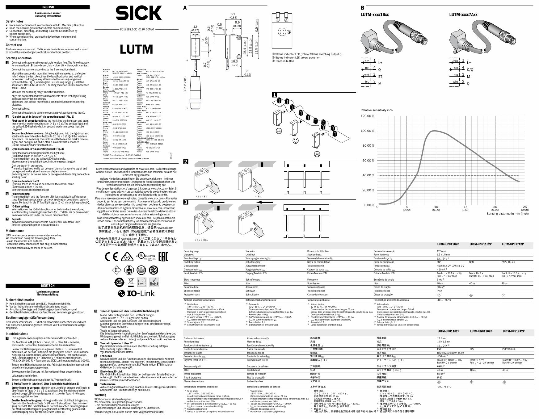
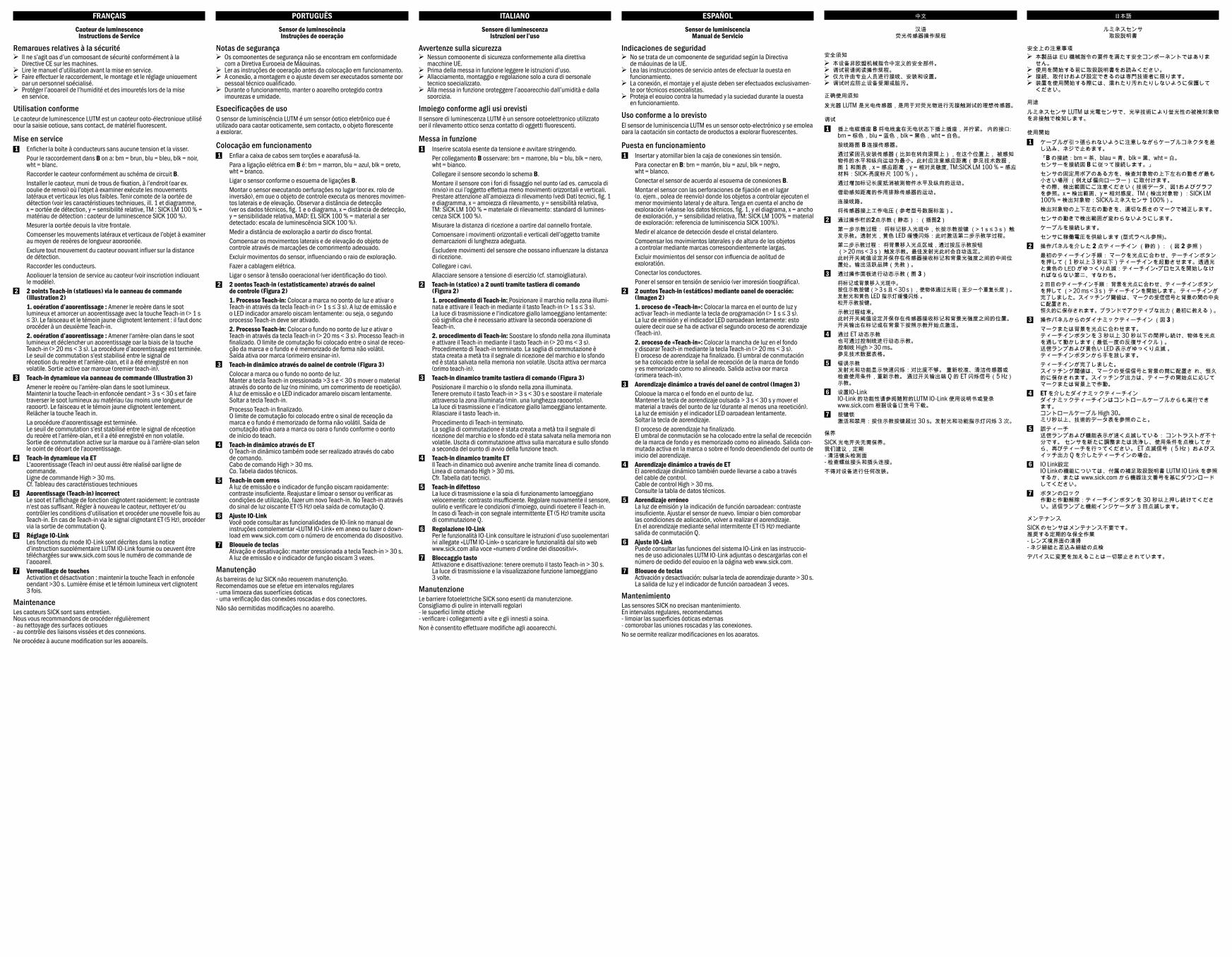
roller) where the test object has the least horizontal and vertical movement. In doing so, pay attention to the sensing range (see technical data, Fig. 1, and diagram, x = sensing range, y = relative sensitivity, TM: SICK LM 100% = sensing material: SICK luminescence scale 100%).
Measure the scanning range from the front lens. Align the horizontal and vertical movements of the test object using
correspondingly long markings. Make sure that sensor movement does not influence the scanning distance.
Connect cables. Connect photoelectric switch to operating voltage (see type label). 2 “2 point teach-in (static)” via operating panel (Fig. 2) First teach-in procedure: Bring the mark into the light spot and start
teach-in with teach-in pushbutton (> 1 s ≤ 3 s). The emitted light and the yellow LED flash slowly: i. e. second teach-in process must be triggered.
Second teach-in procedure: Bring background into the light spot and start teach-in with teach-in button (> 20 ms < 3 s). Quit the teach-in procedure. The switching threshold is set between the mark’s receive signal and background and is stored in a nonvolatile manner. Output active by mark (first teach-in).
3 Dynamic teach-in via operating panel (Fig. 3) Bring the mark or background into the light spot.
Hold down teach-in button > 3 s < 30 s. The emitted light and the yellow LED flash slowly. Move material through light spot (min. one repeat length).
Quit the teach-in procedure. The switching threshold is set between the mark‘s receive signal and background and is stored in a nonvolatile manner. Switching output active on mark or background depending on teach-in starting point.
4 Dynamic teach-in via ET Dynamic teach-in can also be done via the control cable. Control cable High > 30 ms. See technical specifications table
5 Faulty teaching The emitted light and the function LED flash rapidly: insufficient con-trast. Readjust sensor, clean or check application conditions, teach-in again. For teach-in via ET flashlight signal (5 Hz) via switching output Q.
6 IO-Link setting Information on the IO-Link functions can be found in the enclosed supplementary operating instructions for LUTM IO-Link or downloaded from www.sick.com under the device order number.
7 Keylock Activation and deactivation: hold down teach-in button > 30 s. Emitted light and function display flash 3 x.
MaintenanceSICK luminescence sensors are maintenance-free. We recommend doing the following regularly - clean the external lens surfaces. - check the screw connections and plug-in connections.No modifications may be made to devices.
DEUTSCHDEUTSCHLumineszenzsensorBetriebsanleitung
Sicherheitshinweise > Kein Sicherheitsbauteil gemäß EU-Maschinenrichtlinie. > Vor der Inbetriebnahme die Betriebsanleitung lesen. > Anschluss, Montage und Einstellung nur durch Fachpersonal. > Gerät bei Inbetriebnahme vor Feuchte und Verunreinigung schützen.
Bestimmungsgemäße VerwendungDer Lumineszenzsensor LUTM ist ein optoelektronischer Sensor und wird zum optischen, berührungslosen Erfassen von fluoreszierendem Tastgut eingesetzt.
Inbetriebnahme 1 Leitungsdose spannungsfrei aufstecken und festschrauben. Für Anschluss in B gilt: brn = braun, blu = blau, blk = schwarz,
wht = weiß. Sensor laut Anschlussschema B anschließen. Sensor mit Befestigungsbohrungen an Stelle (z. B. Umlenkrolle)
montieren, an der das Prüfobjekt die geringsten Seiten- und Höhenbe-wegungen ausführt. Dabei Tastweite beachten (s. technische Daten, Abb. 1 und Diagramm, x = Tastweite, y = relative Empfindlichkeit, TM: SICK LM 100 % = Tastmaterial: SICK-Lumineszenzmaßstab 100 %).
Seiten- und Höhenbewegungen des Prüfobjektes durch entsprechend lange Markierungen ausgleichen.
Bewegungen des Sensors mit Tastweiteneinfluss ausschließen. Leitungen anschließen. Sensor an Betriebsspannung legen (s. Typenaufdruck). 2 2 Punkt Teach-in (statisch) über Bedienfeld (Abbildung 2) Erster Teach-in-Vorgang: Marke in den Lichtfleck bringen und Teach-in
über Teach-in-Taste (> 1 s ≤ 3 s) auslösen. Das Sendelicht und die gelbe Anzeige LED blinken langsam: d. h. zweiter Teach-in-Vorgang muss ausgelöst werden.
Zweiter Teach-in-Vorgang: Hintergrund in den Lichtfleck bringen und Teach-in über Teach-in-Taste (> 20 ms < 3 s) auslösen. Teach-in-Vor-gang beendet. Die Schaltschwelle hat sich zwischen Empfangssignal der Marke und Hintergrund gelegt und ist nichtflüchtig gespeichert. Schaltausgang aktiv auf Marke (erster Teach-in).
LUTM
--------------------------------------------------------- 8017182.16IC 0120 COMAT ------------------------------------------------------
A
3 Teach-in dynamisch über Bedienfeld (Abbildung 3) Marke oder Hintergrund in den Lichtfleck bringen.
Teach-in Taste > 3 s < 30 s gedrückt halten Sendelicht und die gelbe Anzeige LED blinken langsam Material durch den Lichtfleck bewegen (min. eine Rapportlänge) Teach-in Taste loslassen.
Teach-in-Vorgang beendet. Die Schaltschwelle hat sich zwischen Empfangssignal der Marke und Hintergrund gelegt und ist nichtflüchtig gespeichert. Schaltausgang aktiv auf Marke oder auf Hintergrund je nach Startpunkt des Teachs.
4 Teach-in dynamisch über ET Dynamischer Teach-in kann auch über Steuerleitung erfolgen. Steuerleitung High > 30 ms. Vgl. Tabelle technische Daten.
5 Fehlteach Das Sendelicht und die Funktionsanzeige blinken schnell: Kontrast nicht ausreichend. Sensor neu justieren, reinigen bzw. Einsatzbedin-gungen prüfen, erneut einlernen. Bei Teach-in über ET Blinksignal (5 Hz) über Schaltausgang Q.
6 Einstellung IO-Link Die IO-Link Funktionalitäten bitte der beiliegenden Zusatz-Betriebs- anleitung LUTM IO-Link entnehmen oder über www.sick.com unter der Geräte-Bestellnummer downloaden.
7 Tastensperre Aktivierung und Deaktivierung: Teach-in Taste > 30 s gedrückt halten.Sendelicht und Funktionsanzeige blinken 3 x.
WartungSICK-Sensoren sind wartungsfrei. Wir empfehlen, in regelmäßigen Abständen – die optischen Grenzflächen zu reinigen, – Verschraubungen und Steckverbindungen zu überprüfen.Veränderungen an Geräten dürfen nicht vorgenommen werden.
L+
Q
ET
M
1
4
2
3
brn
blk
wht
blu
B
LUTM-UP81162P LUTM-UN81162P LUTM-UP817A2P
Scanning range Tastweite Distance de détection Campo de exploração 12.5 mmLight spot Lichtfleck Spot lumineux Ponto luminoso 1.5 x 1.5 mmSupply voltage UB Versorgungsspannung UB Tension d‘alimentation UB Tensão de força UB 12 ... 24 V 1)
Switching output Schaltausgang Sortie de commutation Saída de comutação PNP NPN PNP / IO-LinkOutput voltage Ausgangsspannung Tension de sortie Tensão de saída HIGH: UB ≤ 2V; LOW: ca. 0 VOutput current Imax. Ausgangsstrom Imax. Courant de sortie Imax. Corrente de saída Imax. ≤ 50 mA 2)
Input, teach-in (ET) Eingang Teach-in (ET) Entrée Teach-in (ET) Entrada Teach-in (ET) Teach: U = 10.8 V … < UB Run: U < 2 V or open
Teach: U < 2 V Run: U > UB – 2 V or open
Teach: U = 10.8 V … < UB Run: U < 2 V or open
Signal sequence Schaltfrequenz Fréquence Sequência de sin ais 6 kHz 3)
Jitter Jitter Scintillement Jitter 40 µs 40 µs 40 µsResponse time Ansprechzeit Temps de réponse Tempo de reação 80 µs 4)
Enclosure rating Schutzart Type de protection Tipo de proteção IP 67Protection class Schutzklasse Classe de protection Classe de proteção
Ambient operating temperature Betriebsumgebungstemperatur Température ambiante Temperatura ambiente de operação -10 ... +55 °C1) Limit values:
12 V (-10 %) ... 24 V (+20 %). Power consumption without load < 50 mA Operation in short-circuit protected network max. 8 A ripple max. 5 VCC
2) At supply voltage > 24 V, Imax. = 30 mA. Imax. is consumption count of all QN.
3) Scanning ratio 1:14) Signal transit time with resistive load
1) Grenzwerte: 12 V (-10 %) ... 24 V (+20 %). Stromaufnahme ohne Last < 50 mA Betrieb in kurzschlussgeschütztem Netz max. 8 A. Restwelligkeit ≤ 5 VCC
2) Bei Versorgungsspannung > 24 V, Imax. = 30 mA. Imax. ist Summenstrom aller QN.
3) Tastverhältnis 1:14) Signallaufzeit bei ohmscher Last
1) Valeurs limites: 12 V (-10 %) ... 24 V (+20 %). Consommation de courant sans charge < 50 mA Service dans un réseau protégév contre les courts-circuits 8 A au max. Ondulation résiduelle max. 5 VCC
2) Pour tension d‘alimentation > 24 V Imax. = 30 mA. Imax. est la somme des courant de tous les QN
3) Rapport de 1:14) Durée du signal en charge ohmique
1) Valores limite: 12 V (-10 %) ... 24 V (+20 %). Consumo de corrente sem carga < 50 mA Operação em rede protegida contra curto-circuitos max. 8 A Ondulação residual max. 5 VCC
2) No caso de tensão de alimentação > 24 V, Imax. = 30 mA. Imax. é a corrente total de todos QN.
3) Fator de detecção 1:14) Tempo de transição do sinal com carga ôhmica
LUTM-UP81162P LUTM-UN81162P LUTM-UP817A2P
Distanza di ricezione Alcance de exploratión 感应距离 検出範囲 12.5 mmPunto luminoso Mancha de luz 光斑 光点 1.5 x 1.5 mmTensione di alimentazione UB Tensión de alimentación UB 电源电压 UB 供給電圧 UB 12 ... 24 V 1)
Uscita di commutazione Salida conmutada 开关输出端 スイッチング出力 PNP NPN PNP / IO-LinkTensione all'uscita Tension de salida 输出压 出力電圧 HIGH: UB ≤ 2V; LOW: ca. 0 VCorrente di uscita Imax. Corriente de salida Imax. 输出电流Imax. 最大出力電流 Imax. ≤ 50 mA 2)
Ingresso Teach-in (ET) Entrada Teach-in (ET) 示教输入(ET) ティーチイン入力 (ET) Teach: U = 10.8 V … < UB Run: U < 2 V or open
Teach: U < 2 V Run: U > UB – 2 V or open
Teach: U = 10.8 V … < UB Run: U < 2 V or open
Sequenza signali Secuencia de señales 开关频率 スイッチング頻度 6 kHz 3)
Jitter Inestabilidad 抖动 ステップ偏差 (Jitter) 40 µs 40 µs 40 µsTempo di risposta Tiempo de reacción 触发时间 応答時間 80 µs 4)
Tipo di protezione Tipo de protección 保护种类 保護等級 IP 67Classe di protezione Protección clase 保护级别 保護クラス
Temperatura ambiente circostante Temperatura ambiente de servicio 工作环境-温度 使用周囲温度 -10 ... +55 °C1) Valori limite:
12 V (-10 %) ... 24 V (+20 %). Assorbimento di corrente senza carico < 50 mA Funzionamento in rete con protezione dai cortocircuiti max. 8 A ondulazione residua max. 5 VCC
2) Per una tensione di alimentazione> 24 V, Imax. = 30 mA. Imax. è la corrente cumulativa di tutti i QN.
3) Rapporto di lavoro 1:14) Tempo di continuare de segnale a resistenza ohmica
1) Valores límite: 12 V (-10 %) ... 24 V (+20 %). Consumo de corriente sin carga < 50 mA Funcionamiento en la red protegida contra cortocircuito, max. 8 A ondulación residual max. 5 VCC
2) Tensión de alimentación > 24 V, Imax. = 30 mA. Imax. es la corriente total de todos los QN.
3) Relación de exploración 1:14) Duración de la señal con carga óhmica
1) 操作电流: 12 V (-10 %) ... 24 V (+20 %)。 耗用电流无负荷< 50 mA 在防短路的网络里, 最大8 极限值剩余波纹度 max. 5 VCC
2) 当供电电压 > 24 V 时,最大电流 Imax. = 30 mA。 最大电流 Imax. 是所有 QN 的总电流。
3) 感应比:1:14) 电阻性负载时,传感器检测到变化时输出信号的转 换时间
1) 限界値: 12 V (-10 %) ... 24 V (+20 %). 負荷なしでの電流消費 < 50 mA 短絡防止回路での動作 最大 8 A、 残留リップル最大 5 VCC
2) 電源電圧が> 24 V の場合、Imax. = 30 mA。 Imax. はすべての QN の全電流。
3) 検出比 1:14) 抵抗負荷における信号遷移時間
L+
C/Q
M
Q
1
4
3
2
brn
blk
blu
wht
9(0
.35)
9.7
(0.3
8)
21(0.83)
31.5
(1.2
4)
28.5
(1.1
2)
25.4
(1.0
0)
0.5
(0.0
2)
0.5(0.02)
3(0.12)
18.3(0.72)
9.9(0.39)
0.9
(0.0
4)
12(0.47)
305
(12.
01)
2
3
> 3 s ≤ 30 s
> 1 s ≤ 3 s < 3 s
5(0.20)
0 10(0.39)
15(0.59)
20(0.79)
25(0.98)
0.00 %
20.00 %
40.00 %
60.00 %
80.00 %
100.00 %
120.00 %
Sensing distance in mm (inch)
Relative sensitivity in %
LUTM-xxxx16xx LUTM-xxxx7Axx
1
1 Status indicator LED, yellow: Status switching output Q2 Status indicator LED green: power on3 Teach-in button
1 2
3
2011/65/EU
More representatives and agencies at www.sick.com ∙ Subject to change without notice ∙ The specified product features and technical data do not
represent any guarantee.Weitere Niederlassungen finden Sie unter www.sick.com ∙ Irrtümer
und Änderungen vorbehalten ∙ Angegebene Produkteigenschaften und technische Daten stellen keine Garantieerklärung dar.
Plus de représentations et d’agences à l’adresse www.sick.com ∙ Sujet à modification sans préavis ∙ Les caractéristiques de produit et techniques
indiquées ne constituent pas de déclaration de garantie.Para mais representantes e agências, consulte www.sick.com ∙ Alterações
poderão ser feitas sem prévio aviso ∙ As características do produto e os dados técnicos apresentados não constituem declaração de garantia.Altri rappresentanti ed agenzie si trovano su www.sick.com ∙ Contenuti
soggetti a modifiche senza preavviso ∙ Le caratteristiche del prodotto e i dati tecnici non rappresentano una dichiarazione di garanzia.
Más representantes y agencias en www.sick.com ∙ Sujeto a cambio sin previo aviso ∙ Las características y los datos técnicos especificados no
constituyen ninguna declaración de garantía.欲了解更多代表机构和代理商信息,请登录 www.sick.com ∙ 如有更改 , 不另行通知 ∙ 对所给出的产品特性和技术参数
的正确性不予保证。その他の営業所は www.sick.com よりご覧ください ∙ 予告なしに変更されることがあります ∙ 記載されている製品機能およ
び技術データは保証を明示するものではありません。
BZ in
t49
Detailed addresses and further locations at www.sick.com
Australia Phone +61 (3) 9457 0600 1800 33 48 02 – tollfreeAustria Phone +43 (0) 2236 62288-0Belgium/Luxembourg Phone +32 (0) 2 466 55 66Brazil Phone +55 11 3215-4900Canada Phone +1 905.771.1444Czech Republic Phone +420 234 719 500Chile Phone +56 (2) 2274 7430China Phone +86 20 2882 3600Denmark Phone +45 45 82 64 00Finland Phone +358-9-25 15 800France Phone +33 1 64 62 35 00Germany Phone +49 (0) 2 11 53 010Greece Phone +30 210 6825100 Hong Kong Phone +852 2153 6300Hungary Phone +36 1 371 2680India Phone +91-22-6119 8900Israel Phone +972 97110 11 Italy Phone +39 02 27 43 41Japan Phone +81 3 5309 2112Malaysia Phone +603-8080 7425Mexico Phone +52 (472) 748 9451
Netherlands Phone +31 (0) 30 229 25 44New Zealand Phone +64 9 415 0459 0800 222 278 – tollfreeNorway Phone +47 67 81 50 00Poland Phone +48 22 539 41 00Romania Phone +40 356-17 11 20Russia Phone +7 495 283 09 90Singapore Phone +65 6744 3732Slovakia Phone +421 482 901 201Slovenia Phone +386 591 78849South Africa Phone +27 10 060 0550South Korea Phone +82 2 786 6321/4Spain Phone +34 93 480 31 00Sweden Phone +46 10 110 10 00Switzerland Phone +41 41 619 29 39Taiwan Phone +886-2-2375-6288Thailand Phone +66 2 645 0009Turkey Phone +90 (216) 528 50 00United Arab Emirates Phone +971 (0) 4 88 65 878United Kingdom Phone +44 (0)17278 31121USA Phone +1 800.325.7425 Vietnam Phone +65 6744 3732
SICK AG, Erwin-Sick-Strasse 1, D-79183 Waldkirch
2006/42/EC2006/42/EC
NO
SAFETY
日本語日本語
ルミネスセンサ取扱説明書
安全上の注意事項 > 本製品は EU 機械指令の要件を満たす安全コンポーネントではありま
せん。 > 使用を開始する前に取扱説明書をお読みください。 > 接続、取付けおよび設定できるのは専門技術者に限ります。 > 装置を使用開始する際には、濡れたり汚れたりしないように保護して
ください。
用途ルミネスセンサ LUTM は光電センサで、光学技術により蛍光性の被検対象物を非接触で検知します。
使用開始 1 ケーブルが引っ張られないように注意しながらケーブルコネクタを差
し込み、ネジで止めます。 「B の接続:brn = 茶、blau = 青、blk = 黒、wht = 白。
センサーを接続図 B に従って接続します。」 センサの固定用ボアのある方を、検査対象物の上下左右の動きが最も
小さい場所 (例えば偏向ローラー) に取付けます。 その際、検出範囲にご注意ください(技術データ、図1およびグラフを参照。x = 検出範囲、y = 相対感度、TM(検出対象物):SICK LM 100% = 検出対象物:SICKルミネスセンサ 100%)。
検出対象物の上下左右の動きを、適切な長さのマークで補正します。 センサの動きで検出範囲が変わらないようにします。 ケーブルを接続します。 センサに稼働電圧を供給します (型式ラベル参照)。 2 操作パネルを介した 2 点ティーチイン (静的): (図 2 参照) 最初のティーチイン手順: マークを光点に合わせ、テーチインボタン
を押して(1 秒以上 3 秒以下)ティーチインを起動させます。透過光と黄色の LED がゆっくり点滅:ティーチイン•プロセスを開始しなければならない第二、すなわち。
2 回目のティーチイン手順: 背景を光点に合わせ、ティーチインボタンを押して (> 20 ms < 3 s) ティーチインを開始します。 ティーチインが完了しました。スイッチング閾値は、マークの受信信号と背景の間の中央に配置され、 恒久的に保存されます。ブランドでアクティブな出力(最初に教える)。
3 操作パネルからのダイナミックティーチイン (図 3) マークまたは背景を光点に合わせます。
ティーチインボタンを 3 秒以上 30 秒以下の間押し続け、物体を光点を通して動かします(最低一度の反復サイクル)。 送信ランプおよび黄色い LED 表示がゆっくり点滅 。 ティーチインボタンから手を放します。
ティーチインが完了しました。 スイッチング閾値は、マークの受信信号と背景の間に配置さ れ、恒久的に保存されます。スイッチング出力は、ティーチの開始点に応じてマークまたは背景上で作動。
4 ET を介したダイナミックティーチイン ダイナミックティーチインはコントロールケーブルからも実行できます。 コントロールケーブル High 30。 ミリ秒以上、技術的データ表を参照のこと。
5 誤ティーチ 送信ランプおよび機能表示が速く点滅している: コントラストが不十分です。 センサを新たに調整または洗浄し、使用条件を点検してから、再びティーチを行ってください。 ET 点滅信号 (5 Hz) およびスイッチ出力 Q を介したティーチインの場合。
6 IO Link設定 IO Linkの機能については、付属の補足取扱説明書 LUTM IO Link を参照するか、または www.sick.com から機器注文番号を基にダウンロードしてください。
7 ボタンのロック 作動と作動解除:ティーチインボタンを 30 秒以上押し続けてください。送信ランプと機能インジケータが 3 回点滅します。
メンテナンスSICK のセンサはメンテナンス不要です。 推奨する定期的な保全作業 - レンズ境界面の清掃 - ネジ締結と差込み締結の点検デバイスに変更を加えることは一切禁止されています。
FRANÇAISFRANÇAISCapteur de luminescence
Instructions de Service
Remarques relatives à la sécurité > Il ne s’agit pas d’un composant de sécurité conformément à la
Directive CE sur les machines. > Lire le manuel d’utilisation avant la mise en service. > Faire effectuer le raccordement, le montage et le réglage uniquement
par un personnel spécialisé. > Protéger l’appareil de l’humidité et des impuretés lors de la mise
en service.
Utilisation conformeLe capteur de luminescence LUTM est un capteur opto-électronique utilisé pour la saisie optique, sans contact, de matériel fluorescent.
Mise en service 1 Enficher la boîte à conducteurs sans aucune tension et la visser. Pour le raccordement dans B on a: brn = brun, blu = bleu, blk = noir,
wht = blanc. Raccorder le capteur conformément au schéma de circuit B. Installer le capteur, muni de trous de fixation, à l’endroit (par ex.
poulie de renvoi) où l’objet à examiner exécute les mouvements latéraux et verticaux les plus faibles. Tenir compte de la portée de détection (voir les caractéristiques techniques, ill. 1 et diagramme, x = portée de détection, y = sensibilité relative, TM : SICK LM 100 % = matériau de détection : capteur de luminescence SICK 100 %).
Mesurer la portée depuis la vitre frontale. Compenser les mouvements latéraux et verticaux de l’objet à examiner
au moyen de repères de longueur appropriée. Exclure tout mouvement du capteur pouvant influer sur la distance
de détection. Raccorder les conducteurs. Appliquer la tension de service au capteur (voir inscription indiquant
le modèle). 2 2 points Teach-in (statiques) via le panneau de commande
(Illustration 2) 1. opération d’apprentissage : Amener le repère dans le spot
lumineux et amorcer un apprentissage avec la touche Teach-in (> 1 s ≤ 3). Le faisceau et le témoin jaune clignotent lentement : il faut donc procéder à un deuxième Teach-in.
2. opération d’apprentissage : Amener l‘arrière-plan dans le spot lumineux et déclencher un apprentissage par la biais de la touche Teach-in (> 20 ms < 3 s). La procédure d’apprentissage est terminée. Le seuil de commutation s‘est stabilisé entre le signal de réception du repère et l‘arrière-plan, et il a été enregistré en non volatile. Sortie active par marque (premier teach-in).
3 Teach-in dynamique via panneau de commande (Illustration 3) Amener le repère ou l‘arrière-plan dans le spot lumineux.
Maintenir la touche Teach-in enfoncée pendant > 3 s < 30 s et faire traverser le spot lumineux au matériau (au moins une longueur de rapport). Le faisceau et le témoin jaune clignotent lentement. Relâcher la touche Teach in.
La procédure d‘apprentissage est terminée. Le seuil de commutation s‘est stabilisé entre le signal de réception du repère et l‘arrière-plan, et il a été enregistré en non volatile. Sortie de commutation active sur la marque ou à l‘arrière-plan selon le point de départ de l‘apprentissage.
4 Teach-in dynamique via ET L‘apprentissage (Teach in) peut aussi être réalisé par ligne de commande. Ligne de commande High > 30 ms. Cf. Tableau des caractéristiques techniques
5 Apprentissage (Teach-in) incorrect Le spot et l‘affichage de fonction clignotent rapidement: le contraste n‘est pas suffisant. Régler à nouveau le capteur, nettoyer et/ou contrôler les conditions d‘utilisation et procéder une nouvelle fois au Teach-in. En cas de Teach-in via le signal clignotant ET (5 Hz), procéder via la sortie de commutation Q.
6 Réglage IO-Link Les fonctions du mode IO-Link sont décrites dans la notice d’instruction supplémentaire LUTM IO-Link fournie ou peuvent être téléchargées sur www.sick.com sous le numéro de commande de l’appareil.
7 Verrouillage de touches Activation et désactivation : maintenir la touche Teach in enfoncée pendant >30 s. Lumière émise et le témoin lumineux vert clignotent 3 fois.
MaintenanceLes capteurs SICK sont sans entretien. Nous vous recommandons de procéder régulièrement - au nettoyage des surfaces optiques - au contrôle des liaisons vissées et des connexions.Ne procédez à aucune modification sur les appareils.
PORTUGUÊSPORTUGUÊSSensor de luminescênciaInstruções de operação
Notas de segurança > Os componentes de segurança não se encontram em conformidade
com a Diretiva Europeia de Máquinas. > Ler as instruções de operação antes da colocação em funcionamento. > A conexão, a montagem e o ajuste devem ser executados somente por
pessoal técnico qualificado. > Durante o funcionamento, manter o aparelho protegido contra
impurezas e umidade.
Especificações de usoO sensor de luminiscência LUTM é um sensor óptico eletrônico que é utilizado para captar opticamente, sem contacto, o objeto florescente a explorar.
Colocação em funcionamento 1 Enfiar a caixa de cabos sem torções e aparafusá-la. Para a ligação elétrica em B é: brn = marron, blu = azul, blk = preto,
wht = branco. Ligar o sensor conforme o esquema de ligações B. Montar o sensor executando perfurações no lugar (por ex. rolo de
inversão), em que o objeto de controle executa os menores movimen-tos laterais e de elevação. Observar a distância de detecção (ver os dados técnicos, fig. 1 e o diagrama, x = distância de detecção, y = sensibilidade relativa, MAD: EL SICK 100 % = material a ser detectado: escala de luminescência SICK 100 %).
Medir a distância de exploração a partir do disco frontal. Compensar os movimentos laterais e de elevação do objeto de
controle através de marcações de comprimento adequado. Excluir movimentos do sensor, influenciando o raio de exploração. Fazer a cablagem elétrica. Ligar o sensor à tensão operacional (ver identificação do tipo). 2 2 pontos Teach-in (estatisticamente) através do painel
de controle (Figura 2) 1. Processo Teach-in: Colocar a marca no ponto de luz e ativar o
Teach-in através da tecla Teach-in (> 1 s ≤ 3 s). A luz de emissão e o LED indicador amarelo piscam lentamente: ou seja, o segundo processo Teach-in deve ser ativado.
2. Processo Teach-in: Colocar o fundo no ponto de luz e ativar o Teach-in através da tecla Teach-in (> 20 ms < 3 s). Processo Teach-in finalizado. O limite de comutação foi colocado entre o sinal de recep-ção da marca e o fundo e é memorizado de forma não volátil. Saída ativa por marca (primeiro ensinar-in).
3 Teach-in dinâmico através do painel de controle (Figura 3) Colocar a marca ou o fundo no ponto de luz.
Manter a tecla Teach-in pressionada >3 s e < 30 s mover o material através do ponto de luz (no mínimo, um comprimento de repetição). A luz de emissão e o LED indicador amarelo piscam lentamente. Soltar a tecla Teach-in.
Processo Teach-in finalizado. O limite de comutação foi colocado entre o sinal de recepção da marca e o fundo é memorizado de forma não volátil. Saída de comutação ativa para a marca ou para o fundo conforme o ponto de início do teach.
4 Teach-in dinâmico através de ET O Teach-in dinâmico também pode ser realizado através do cabo de comando. Cabo de comando High > 30 ms. Cp. Tabela dados técnicos.
5 Teach-in com erros A luz de emissão e o indicador de função piscam rapidamente: contraste insuficiente. Reajustar e limpar o sensor ou verificar as condições de utilização, fazer um novo Teach-in. No Teach-in através do sinal de luz piscante ET (5 Hz) pela saída de comutação Q.
6 Ajuste IO-Link Você pode consultar as funcionalidades de IO-link no manual de instruções complementar «LUTM IO-Link» em anexo ou fazer o down-load em www.sick.com com o número de encomenda do dispositivo.
7 Bloqueio de teclas Ativação e desativação: manter pressionada a tecla Teach-in > 30 s. A luz de emissão e o indicador de função piscam 3 vezes.
ManutençãoAs barreiras de luz SICK não requerem manutenção. Recomendamos que se efetue em intervalos regulares - uma limpeza das superfícies ópticas - uma verificação das conexões roscadas e dos conectores.Não são permitidas modificações no aparelho.
ITALIANOITALIANOSensore di luminescenza
Istruzioni per l’uso
Avvertenze sulla sicurezza > Nessun componente di sicurezza conformemente alla direttiva
macchine UE. > Prima della messa in funzione leggere le istruzioni d’uso. > Allacciamento, montaggio e regolazione solo a cura di personale
tecnico specializzato. > Alla messa in funzione proteggere l’apparecchio dall’umidità e dalla
sporcizia.
Impiego conforme agli usi previstiIl sensore di luminescenza LUTM è un sensore optoelettronico utilizzato per il rilevamento ottico senza contatto di oggetti fluorescenti.
Messa in funzione 1 Inserire scatola esente da tensione e avvitare stringendo. Per collegamento B osservare: brn = marrone, blu = blu, blk = nero,
wht = bianco. Collegare il sensore secondo lo schema B. Montare il sensore con i fori di fissaggio nel punto (ad es. carrucola di
rinvio) in cui l’oggetto effettua meno movimenti orizzontali e verticali. Prestare attenzione all’ampiezza di rilevamento (vedi Dati tecnici, fig. 1 e diagramma, x = ampiezza di rilevamento, y = sensibilità relativa, TM: SICK LM 100 % = materiale di rilevamento: standard di lumines-cenza SICK 100 %).
Misurare la distanza di ricezione a partire dal pannello frontale. Compensare i movimenti orizzontali e verticali dell’oggetto tramite
demarcazioni di lunghezza adeguata. Escludere movimenti del sensore che possano influenzare la distanza
di ricezione. Collegare i cavi. Allacciare sensore a tensione di esercizio (cf. stampigliatura). 2 Teach-in (statico) a 2 punti tramite tastiera di comando
(Figura 2) 1. procedimento di Teach-in: Posizionare il marchio nella zona illumi-
nata e attivare il Teach-in mediante il tasto Teach-in (> 1 s ≤ 3 s). La luce di trasmissione e l‘indicatore giallo lampeggiano lentamente: ciò significa che è necessario attivare la seconda operazione di Teach-in.
2. procedimento di Teach-in: Spostare lo sfondo nella zona illuminata e attivare il Teach-in mediante il tasto Teach-in (> 20 ms < 3 s). Procedimento di Teach-in terminato. La soglia di commutazione è stata creata a metà tra il segnale di ricezione del marchio e lo sfondo ed è stata salvata nella memoria non volatile. Uscita attiva per marca (primo teach-in).
3 Teach-in dinamico tramite tastiera di comando (Figura 3) Posizionare il marchio o lo sfondo nella zona illuminata.
Tenere premuto il tasto Teach-in > 3 s < 30 s e spostare il materiale attraverso la zona illuminata (min. una lunghezza rapporto). La luce di trasmissione e l‘indicatore giallo lampeggiano lentamente. Rilasciare il tasto Teach-in.
Procedimento di Teach-in terminato. La soglia di commutazione è stata creata a metà tra il segnale di ricezione del marchio e lo sfondo ed è stata salvata nella memoria non volatile. Uscita di commutazione attiva sulla marcatura e sullo sfondo a seconda del punto di avvio della funzione teach.
4 Teach-in dinamico tramite ET Il Teach-in dinamico può avvenire anche tramite linea di comando. Linea di comando High > 30 ms. Cfr. Tabella dati tecnici.
5 Teach-in difettoso La luce di trasmissione e la spia di funzionamento lampeggiano velocemente: contrasto insufficiente. Regolare nuovamente il sensore, pulirlo e verificare le condizioni d‘impiego, quindi ripetere il Teach-in. In caso di Teach-in con segnale intermittente ET (5 Hz) tramite uscita di commutazione Q.
6 Regolazione IO-Link Per le funzionalità IO-Link consultare le istruzioni d’uso supplementari ivi allegate «LUTM IO-Link» o scaricare le funzionalità dal sito web www.sick.com alla voce «numero d’ordine dei dispositivi».
7 Bloccaggio tasto Attivazione e disattivazione: tenere premuto il tasto Teach-in > 30 s. La luce di trasmissione e la visualizzazione funzione lampeggiano 3 volte.
ManutenzioneLe barriere fotoelettriche SICK sono esenti da manutenzione. Consigliamo di pulire in intervalli regolari - le superfici limite ottiche - verificare i collegamenti a vite e gli innesti a spina.Non è consentito effettuare modifiche agli apparecchi.
ESPAÑOLESPAÑOLSensor de luminiscencia
Manual de Servicio
Indicaciones de seguridad > No se trata de un componente de seguridad según la Directiva
de máquinas de la UE. > Lea las instrucciones de servicio antes de efectuar la puesta en
funcionamiento. > La conexión, el montaje y el ajuste deben ser efectuados exclusivamen-
te por técnicos especialistas. > Proteja el equipo contra la humedad y la suciedad durante la puesta
en funcionamiento.
Uso conforme a lo previstoEl sensor de luminiscencia LUTM es un sensor opto-electrónico y se emplea para la captación sin contacto de productos a explorar fluorescentes.
Puesta en funcionamiento 1 Insertar y atornillar bien la caja de conexiones sin tensión. Para conectar en B: brn = marrón, blu = azul, blk = negro,
wht = blanco. Conectar el sensor de acuerdo al esquema de conexiones B. Montar el sensor con las perforaciones de fijación en el lugar
(p. ejem., polea de reenvío) donde los objetos a controlar ejecuten el menor movimiento lateral y de altura. Tenga en cuenta el ancho de exploración (véanse los datos técnicos, fig. 1, y el diagrama, x = ancho de exploración, y = sensibilidad relativa, TM: SICK LM 100% = material de exploración: referencia de luminiscencia SICK 100%).
Medir el alcance de detección desde el cristal delantero. Compensar los movimientos laterales y de altura de los objetos
a controlar mediante marcas correspondientemente largas. Excluir movimientos del sensor con influencia de aplitud de
exploratión. Conectar los conductores. Poner el sensor en tensión de servicio (ver impresión tipográfica). 2 2 puntos Teach-in (estáticos) mediante panel de operación:
(Imagen 2) 1. proceso de «Teach-in»: Colocar la marca en el punto de luz y
activar Teach-in mediante la tecla de programación (> 1 s ≤ 3 s). La luz de emisión y el indicador LED parpadean lentamente: esto quiere decir que se ha de activar el segundo proceso de aprendizaje (Teach-in).
2. proceso de «Teach-in»: Colocar la mancha de luz en el fondo y disparar Teach-in mediante la tecla Teach-in (> 20 ms < 3 s). El proceso de aprendizaje ha finalizado. El umbral de conmutación se ha colocado entre la señal de recepción de la marca de fondo y es memorizado como no alineado. Salida activa por marca (primera teach-in).
3 Aprendizaje dinámico a través del panel de control (Imagen 3) Coloque la marca o el fondo en el punto de luz.
Mantener la tecla de aprendizaje pulsada > 3 s < 30 s y mover el material a través del punto de luz (durante al menos una repetición). La luz de emisión y el indicador LED parpadean lentamente. Soltar la tecla de aprendizaje.
El proceso de aprendizaje ha finalizado. El umbral de conmutación se ha colocado entre la señal de recepción de la marca de fondo y es memorizado como no alineado. Salida con-mutada activa en la marca o sobre el fondo dependiendo del punto de inicio del aprendizaje.
4 Aprendizaje dinámico a través de ET El aprendizaje dinámico también puede llevarse a cabo a través del cable de control. Cable de control High > 30 ms. Consulte la tabla de datos técnicos.
5 Aprendizaje erróneo La luz de emisión y la indicación de función parpadean: contraste insuficiente. Ajustar el sensor de nuevo. limpiar o bien comprobar las condiciones de aplicación, volver a realizar el aprendizaje. En el aprendizaje mediante señal intermitente ET (5 Hz) mediante salida de conmutación Q.
6 Ajuste IO-Link Puede consultar las funciones del sistema IO-Link en las instruccio-nes de uso adicionales LUTM IO-Link adjuntas o descargarlas con el número de pedido del equipo en la página web www.sick.com.
7 Bloqueo de teclas Activación y desactivación: pulsar la tecla de aprendizaje durante > 30 s. La salida de luz y el indicador de función parpadean 3 veces.
MantenimientoLas sensores SICK no precisan mantenimiento. En intervalos regulares, recomendamos - limpiar las superficies ópticas externas - comprobar las uniones roscadas y las conexiones.No se permite realizar modificaciones en los aparatos.
中文中文
汉语荧光传感器操作规程
安全须知 > 本设备非欧盟机械指令中定义的安全部件。 > 调试前请阅读操作规程。 > 仅允许由专业人员进行接线、安装和设置。 > 调试时应防止设备受潮或脏污。
正确使用须知发光器 LUTM 是光电传感器,是用于对荧光物进行无接触测试的理想传感器。
调试 1 插上电缆插座 B 将电线盒在无电状态下插上插座,并拧紧。 内的接口:
brn = 棕色,blu = 蓝色,blk = 黑色,wht = 白色。 按线路图 B 连接传感器。 通过紧固孔安装传感器(比如在转向滚筒上),在这个位置上, 被感知
物件的水平和纵向运动为最小。此时应注意感应距离(参见技术数据,图 1 和图表,x = 感应距离,y = 相对灵敏度, TM:SICK LM 100 % = 感应材料:SICK-亮度标尺 100 %)。
通过增加标记长度抵消被测物件水平及纵向的运动。 借助感知距离的作用排除传感器的运动。 连接线路。 将传感器接上工作电压(参考型号数据标签)。 2 通过操作栏的2点示教(静态):(插图2) 第一步示教过程: 将标记移入光斑中,长按示教按键 (> 1 s ≤ 3 s) 触
发示教。透射光,黄色 LED 缓慢闪烁:此时激活第二步示教学过程。 第二步示教过程: 将背景移入光点区域,通过按压示教按钮
(> 20 ms < 3 s) 触发示教。最佳发射光此时会自动选定。 此时开关阈值设定并保存在传感器接收标记和背景光强度之间的中间位置处。输出活跃品牌(先教)。
3 通过操作面板进行动态示教(图 3) 将标记或背景移入光斑中。
按住示教按键(> 3 s 且 < 30 s),使物体通过光斑(至少一个重复长度)。 发射光和黄色 LED 指示灯缓慢闪烁 。 松开示教按键。
示教过程结束。 此时开关阈值设定并保存在传感器接收标记和背景光强度之间的位置。开关输出在标记或在背景下按照示教开始点激活。
4 通过 ET 动态示教 也可通过控制线进行动态示教。 控制线 High > 30 ms。 参见技术数据表格。
5 错误示教 发射光和功能显示快速闪烁:对比度不够。 重新校准、清洁传感器或检查使用条件,重新示教。 通过开关输出端 Q 的 ET 闪烁信号(5 Hz)示教。
6 设置IO-Link IO-Link 的功能性请参阅随附的LUTM IO-Link 使用说明书或登录 www.sick.com 根据设备订货号下载。
7 按键锁 激活和禁用:按住示教按键超过 30 s。发射光和功能指示灯闪烁 3 次。
保养SICK 光电开关无需保养。 我们建议,定期 - 清洁镜头检测面 - 检查螺丝接头和插头连接。不得对设备进行任何改装。