Embed Size (px)
Citation preview

Floor Standing Concealed Floor Standing
Original instruction
Please read this installation manual completely before installing the product.Installation work must be performed in accordance with the national wiring standards by authorized personnel only.Please retain this installation manual for future reference after reading it thoroughly.
INSTALLATION MANUAL
AIRCONDITIONER
P/NO : MFL65003109
http://www.lghvac.comwww.lg.com
Copyright © 2014 - 2018 LG Electronics Inc. All Rights Reserved.
ENGLIS
HFRANÇAIS
ESPAÑOL

2 Indoor Unit
Floor Standing Concealed Floor Standing Type Indoor Unit Installation Manual
TABLE OF CONTENTS
o Four type "A" screws o Connecting cable
o Pipes: Gas sideLiquid side(Refer to ProductData)
o Insulation materialso Additional drain pipe
o Level gaugeo Screw drivero Electric drillo Hole core drill
o Flaring tool seto Specified torque wrenches
(different depending on model No.)o Spanner.......Half union
o A glass of watero Screw driver
o Hexagonal wrencho Gas-leak detectoro Vacuum pumpo Gauge manifold
o Owner's manualo Thermometer
Features...................................3
Safety Precautions.................4
Installation
Selection the best location....7
How to connect wirings.........9
Wiring Connection.................9
Indoor Unit Drain Piping......10
Dip Switch Setting...............13
Group Control Setting .........14
Model Designation ..............18
Airborne Noise Emission ....18
Limiting concentration .........18
Installation Requirements Required Parts Required Tools

Installation Manual 3
FeatureENGLIS
H
Features
Name Drain hose ScrewInsulation for
fittingClamp
(Tie Wrap)
Conduitmounting
plate
Quantity 1 EA 4 EA 1 each. 8 EA 1 EA
Shape
(Other)
• Owner’smanual
• Installationmanual
for gas pipe
for liquid pipe
Installation Tool
Air Inlet
Air filter(At Air Inlet)
Remote ControllerAir Outlet
Control panel
Control panel
Air Filter
Air Inlet
Remote Controller
TEMP
[CEA/CFA Type]
[CEU/CFU Type]

Safety Precautions
4 Indoor Unit
Safety PrecautionsTo prevent injury to the user or other people and property damage, the following instructions must befollowed.n Incorrect operation due to ignoring instruction will cause harm or damage. The seriousness is classi-
fied by the following indications.
n Meanings of symbols used in this manual are as shown below.
WARNING
CAUTION
This symbol indicates the possibility of death or serious injury.
This symbol indicates the possibility of injury or damage to properties only.
Be sure not to do.
Be sure to follow the instruction.
WARNING
Installation• Do not use a defective or underrated circuit breaker. Use this appliance on a dedicated circuit.
- There is risk of fire or electric shock.
• For electrical work, contact the dealer, seller, a qualified electrician, or an Authorized Service Center.- Do not disassemble or repair the product. There is risk of fire or electric shock.
• Always ground the product.- There is risk of fire or electric shock.
• Install the panel and the cover of control box securely.- There is risk of fire or electric shock.
• Always install a dedicated circuit and breaker.- Improper wiring or installation may cause fire or electric shock.
• Use the correctly rated breaker or fuse.- There is risk of fire or electric shock.
• Do not modify or extend the power cable.- There is risk of fire or electric shock.
• Do not install, remove, or re-install the unit by yourself (customer).- There is risk of fire, electric shock, explosion, or injury.
• Be cautious when unpacking and installing the product.- Sharp edges could cause injury. Be especially careful of the case edges and the fins on the con-
denser and evaporator.
• For installation, always contact the dealer or an Authorized Service Center.- There is risk of fire, electric shock, explosion, or injury.
• Do not install the product on a defective installation stand.- It may cause injury, accident, or damage to the product.
• Be sure the installation area does not deteriorate with age.- If the base collapses, the air conditioner could fall with it, causing property damage, product fail-
ure, and personal injury.
• Do not turn on the breaker or power under condition that front panel, cabinet, top cover, control boxcover are removed or opened. - Otherwise, it may cause fire, electric shock, explosion or death.

Installation Manual 5
Safety PrecautionsENGLIS
H
• Use a vacuum pump or Inert (nitrogen) gas when doing leakage test or air purge. Do not compressair or Oxygen and Do not use Flammable gases. Otherwise, it may cause fire or explosion.- There is the risk of death, injury, fire or explosion.
Operation• Do not let the air conditioner run for a long time when the humidity is very high and a door or a win-
dow is left open.- Moisture may condense and wet or damage furniture.
• Take care to ensure that power cable could not be pulled out or damaged during operation.- There is risk of fire or electric shock.
• Do not place anything on the power cable.- There is risk of fire or electric shock.
• Do not plug or unplug the power supply plug during operation.- There is risk of fire or electric shock.
• Do not touch(operate) the product with wet hands.- There is risk of fire or electrical shock.
• Do not place a heater or other appliances near the power cable.- There is risk of fire and electric shock.
• Do not allow water to run into electric parts.- It may cause There is risk of fire, failure of the product, or electric shock.
• Do not store or use flammable gas or combustibles near the product.- There is risk of fire or failure of product.
• Do not use the product in a tightly closed space for a long time.- Oxygen deficiency could occur.
• When flammable gas leaks, turn off the gas and open a window for ventilation before turn the prod-uct on.- Do not use the telephone or turn switches on or off. There is risk of explosion or fire.
• If strange sounds, or small or smoke comes from product. Turn the breaker off or disconnect thepower supply cable.- There is risk of electric shock or fire.
• Stop operation and close the window in storm or hurricane. If possible, remove the product from thewindow before the hurricane arrives.- There is risk of property damage, failure of product, or electric shock.
• Do not open the inlet grill of the product during operation. (Do not touch the electrostatic filter, if theunit is so equipped.)- There is risk of physical injury, electric shock, or product failure.
• When the product is soaked (flooded or submerged), contact an Authorized Service Center.- There is risk of fire or electric shock.
• Be cautious that water could not enter the product.- There is risk of fire, electric shock, or product damage.
• Ventilate the product from time to time when operating it together with a stove, etc.- There is risk of fire or electric shock.
• Turn the main power off when cleaning or maintaining the product.- There is risk of electric shock.
• When the product is not be used for a long time, disconnect the power supply plug or turn off thebreaker.- There is risk of product damage or failure, or unintended operation.
• Take care to ensure that nobody could step on or fall onto the outdoor unit.- This could result in personal injury and product damage.

Safety Precautions
6 Indoor Unit
Installation• Always check for gas (refrigerant) leakage after installation or repair of product.
- Low refrigerant levels may cause failure of product.
• Install the drain hose to ensure that water is drained away properly.- A bad connection may cause water leakage.
• Keep level even when installing the product. - To avoid vibration or water leakage.
• Do not install the product where the noise or hot air from the outdoor unit could damage the neigh-borhoods.- It may cause a problem for your neighbors.
• Use two or more people to lift and transport the product. - Avoid personal injury.
• Do not install the product where it will be exposed to sea wind (salt spray) directly.- It may cause corrosion on the product. Corrosion, particularly on the condenser and evaporator
fins, could cause product malfunction or inefficient operation.
Operation• Do not expose the skin directly to cool air for long periods of time. (Don't sit in the draft.)
- This could harm to your health.
• Do not use the product for special purposes, such as preserving foods, works of art, etc. It is a con-sumer air conditioner, not a precision refrigeration system.- There is risk of damage or loss of property.
• Do not block the inlet or outlet of air flow.- It may cause product failure.
• Use a soft cloth to clean. Do not use harsh detergents, solvents, etc.- There is risk of fire, electric shock, or damage to the plastic parts of the product.
• Do not touch the metal parts of the product when removing the air filter. They are very sharp!- There is risk of personal injury.
• Do not step on or put anyting on the product. (outdoor units)- There is risk of personal injury and failure of product.
• Always insert the filter securely. Clean the filter every two weeks or more often if necessary.- A dirty filter reduces the efficiency of the air conditioner and could cause product malfunction or damage.
• Do not insert hands or other objects through the air inlet or outlet while the product is operated.- There are sharp and moving parts that could cause personal injury.
• Do not drink the water drained from the product.- It is not sanitary and could cause serious health issues.
• Use a firm stool or ladder when cleaning or maintaining the product.- Be careful and avoid personal injury.
• Replace the all batteries in the remote control with new ones of the same type. Do not mix old andnew batteries or different types of batteries.- There is risk of fire or explosion.
• Do not recharge or disassemble the batteries. Do not dispose of batteries in a fire.- They may burn or explode.
• If the liquid from the batteries gets onto your skin or clothes, wash it well with clean water. Do notuse the remote if the batteries have leaked.- The chemicals in batteries could cause burns or other health hazards.
• If you eat the liquid from the batteries, brush your teeth and see doctor. Do not use the remote if thebatteries have leaked. - The chemicals in batteries could cause burns or other health hazards.
CAUTION

Installation Manual 7
InstallationENGLIS
H
InstallationSelection of the best location
Indoor unitInstall the air conditioner in the location that satis-fies the following conditions.• The place shall easily bear a load exceeding four
times the indoor unit’s weight.• Sufficient space should be available to inspect
the unit as in the figure shown on the right. • The place where the unit is installed shall be lev-
eled.• The place shall be suitable for easy connection of
the indoor unit with the outdoor unit.• The place where the unit is installed should not
be affected by electrical noise.• The place where air circulation in the room will be
good .• There should not be any heat source or steam
near the unit
Service spaceSelect an installation site where the following con-ditions are satisfied and that meets your cus-tomer's approval.• Where the floor is strong enough to bear the
indoor unit weight.• Where the floor is not significantly inclined.• Where nothing blocks the air passage.• Where condensate can be properly drained.• Where sufficient clearance for installation and
maintenance can be ensured.• Where there is no possibility of flammable gas
leakage.• Where optimum air distribution can be ensured.• Where piping between indoor and outdoor units
is possible within the allowable limit (Refer to theinstallation manual of the outdoor unit.)
• Keep the indoor and outdoor unit, power cableand transmission wiring, at least 1m from TVsand radios, to prevent distorted pictures and stat-ic.(Depending on the type and source of the elec-trical waves, static may be heard even whenmore than 1 m away.)
654
80 o
r mor
e
B or more
Maintenance area
Window
A or more
20 o
rm
ore
100 ormore
100 ormore
175 ormore
150 ormore
Front side
Base
Air flowdirection
Air inletdirection
1000 or more
Window
(Unit: mm)
[IMPORTANT]Leave sufficient clearance for air inlet and maintenance.
Type A B
CEU Type 788 1080
CFU Type 1066 1358

8 Indoor Unit
Installation
Bolt pitch
(Unit:mm)
198
A
270
(1)
(1)(2)
(2)
(3)
How to open/close front panel
• Positioning of holes for fastening to the wall
• How to open/close the front panel
(1) Open the lid of control panel(Both left and right)
(2) Remove screws(Both left and right)
(3) Lift the front panel of the unit• To close, perform the procedure in opposite
order.
1. Use the installationmount for installation. Checkwhether the wall is strong enough to bear theweight of the unit or not. if there is a risk, rein-force the wall before installing the unit.
2. The unit requires a minimum 100 mm clearanceon the underside for air intake. Also, ensure theunit is level when installed so that drainageflows smoothly. If inclined, water can leak.
3. By a state of the wall, operating sound maybecome bigger.
(Unit:mm)
Capacity(Btu/h) A
CE 858
CF 1136

Installation Manual 9
InstallationENGLIS
H
How to connect wirings
Remove the electric parts Box cover and connect the wiring
Power Supply wiringground wiring(Field wiring)
Transmission wiring(Field wiring)
Connect the wires to the terminals on the control board individually according to the outdoor unit connection.• Ensure that the color of the wires of outdoor unit and the terminal No. are the same as those of indoor unit respectively.
Clamping of cables1) Arrange 2 power cables on the control panel.2) First, fasten the steel clamp with a screw to the inner boss of control panel.3) For the cooling model, fix the other side of the clamp with a screw strongly. For the heat pump model, put the
AWG18 cable(thinner cable) on the clamp and tighten it with a plastic clamp to the other boss of the control panel.
A - - - - - -B AB
GND 12VDRY2DRY1INTERNETIDUSODU
Outdoor UnitIndoor Unit
Terminal Block Indoor Terminal Block Indoor
L(L1) N(L2)
GN
/YL
Indoor Power Input
Wired RemoteController
YL RD BK A B
Wiring Connection
WARNING : Make sure that the screws of the terminal are free from looseness.

Installation
10 Indoor Unit
1. Use the heat insulation material for the refrigerantpiping which has an excellent heat-resistance(over 120°C).
2. Precautions in high humidity circumstance:This air conditioner has been tested according tothe "ISO Conditions with Mist" and confirmed thatthere is not any default. However, if it is operatedfor a long time in high humid atmosphere (dewpoint temperature: more than 23°C), water dropsare liable to fall. In this case, add heat insulationmaterial according to the following procedure:• Heat insulation material to be prepared... EPDM
(Ethylene Propylene Diene Methylene)-over120°C the heat-resistance temperature.
• Add the insulation over 10mm thickness at highhumidity environment.
After inspecting pipe joints for gas leakage, be sureto insulate wit the accessory joint insulation for fit-ting while referrig to the figure. (Fasten both endswith clamps)
Indoor unit
Thermal insulator (accessory)
Fastening band (accessory)
Insulation for fitting (accessory)
(For liquid piped)
Insulation for fitting (accessory)
(For gas piped) liquid pipe
Refrigerant piping
Clamp (6)(4 accessory)
HEAT INSULATION
Drain piping work
• Drain piping must have downward (1/50 to 1/100): be sure not to provide up-and-down slope to pre-vent reverse flow.
• During drain piping connection, be careful not to exert extra force on the drain port on the indoor unit.• The outside diameter of the drain connection on the inddor unit is 21mm.
• Be sure to install heat insulation on the drain piping
• If converging multiple dranin pipes, install according to the procedure shown below.
• After piping work is finished check drainage flows smothly.• Be sure to insulate all indoor units.
Piping material: Polyvinyl chloride pipe 25mm and pipe fittings
Heat insulation material: Polyethylene foam with thickness more than 10 mm.
Slope downwards at a gradientof at least 1/100

Installation Manual 11
InstallationENGLIS
H
CAUTION: After the confirmation of the above conditions, prepare the wiring as follows:
1) Never fail to have an individual power specialized for the air conditioner. Asfor the method of wiring, be guided by the circuit diagram posted on the insideof control box cover.
2) Provide a circuit breaker switch between power source and the unit.
3) The screws which fasten the wiring in the casing of electrical fittings are liableto come loose from vibrations to which the unit is subjected during the courseof transportation. Check them and make sure that they are all tightly fastened.(If they are loose, it could give rise to burn-out of the wires.)
4) Specification of power source
5) Confirm that electrical capacity is sufficient.
6) Be sure that the starting voltage is maintained at more than 90 percent of therated voltage marked on the name plate.
7) Confirm that the cable thickness is as specified in the power sources specifi-cation. (Particularly note the relation between cable length and thickness.)
8) Never fail to equip a leakage breaker where it is wet or moist.
9) The following troubles would be caused by voltage drop-down.• Vibration of a magnetic switch, damage on the contact point, fuse breaking, distur-
bance by the normal function of an overload protection device.• Proper starting power is not given to the compressor.
HAND OVERTeach the customer the operation and maintenance procedures, using the operation manual. (air filter cleaning, temperature control, etc.)

Installation
12 Indoor Unit
CAUTION :
The connecting cable connected to the indoor and outdoor unit should be complied with the fol-lowing specifications (This equipment shall be provided with a cord set complying with thenational regulation).
If the supply cord is damaged, it must be replaced by a special cord or assembly available fromthe manufacturer of its service agent.
u Precautions when laying power and ground wiringUse round pressure terminals for connections to the power terminal block.When laying ground wiring, you must use round pressure terminals.
When none are available, follow the instructions below.
• Do not connect wiring of different thicknesses to the power terminal block. (Slack in the power wiringmay cause abnormal heat.)
• When connecting wiring which is the same thickness, do as shown in the figure below.
• For wiring, use the designated power wire and connect firmly, then secure to prevent outside pressurebeing exerted on the terminal block.
• Use an appropriate screwdriver for tightening the terinal screws. A screwdriver with a small head willstrip the head and make proper tighterning impossible.
• Over-tightening the terminal screws may break them.
AWG1820mm
35±5mm
GN/YL
10±3mm
Round pressure terminalPower wire(Ground wire)

Installation Manual 13
InstallationENGLIS
H
Dip Switch Setting
For Multi V Models, DIP switch 1, 2, 6, 8 must be set OFF.
CAUTION
Function Description Setting Off Setting On DefaultSW1 Communication N/A (Default) - - OffSW2 Cycle N/A (Default) - - Off
SW3 Group ControlSelection of Master orSlave
Master Slave Off
SW4Dry ContactMode
Selection of Dry Contact Mode
Wired/Wireless remotecontroller
selection of Manual or Autooperation Mode
Auto Off
SW5 InstallationFan continuous operation
Continuous operation Re-moval
- Off
SW6 Heater linkage N/A - - Off
SW7
Ventilator link-age
Selection of Ventilatorlinkage
Linkage Removal Working
OffVane selection(Console)
Selection of up/downside Vane
Up side + Down side VaneUp side Vane
Only
Region selec-tion
Selection tropical re-gion
General modelTropicalmodel
SW8 Etc. Spare - - Off
1. Indoor Unit
2. Outdoor Unit
In case that the products meet specific conditions, “Auto addressing” function can start automaticallywith the improved speed by turning the DIP switch #3 of the outdoor unit and resetting the power.
※ Specific conditions:- All names of the indoor units are ARNU****4.- The serial number of Multi V super IV (outdoor units) is after October 2013.
DIP switch 7 segment
Outdoor Unit PCB Outdoor Unit DIP Switch
Installation
14 Indoor Unit
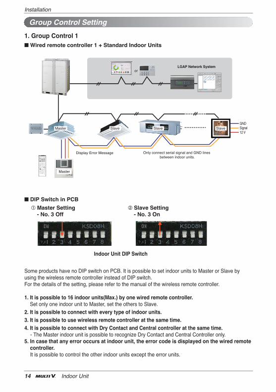
Group Control Setting
Master
GNDSignal12 V
LGAP Network System
Master Slave Slave Slave
Display Error Message Only connect serial signal and GND lines between indoor units.
or
1. Group Control 1n Wired remote controller 1 + Standard Indoor Units
Some products have no DIP switch on PCB. It is possible to set indoor units to Master or Slave byusing the wireless remote controller instead of DIP switch.For the details of the setting, please refer to the manual of the wireless remote controller.
1. It is possible to 16 indoor units(Max.) by one wired remote controller.Set only one indoor unit to Master, set the others to Slave.
2. It is possible to connect with every type of indoor units.3. It is possible to use wireless remote controller at the same time.4. It is possible to connect with Dry Contact and Central controller at the same time.
- The Master indoor unit is possible to recognize Dry Contact and Central Controller only.5. In case that any error occurs at indoor unit, the error code is displayed on the wired remote
controller.It is possible to control the other indoor units except the error units.
n DIP Switch in PCB
¿ Master Setting- No. 3 Off
¡ Slave Setting- No. 3 On
Indoor Unit DIP Switch

Installation Manual 15
InstallationENGLIS
H
GNDSignal12 V
LGAP Network System
Master Master Slave Slave
Donʼt connect serial 12V line
or
Display Error Message
Master Master
h It is possible to connect indoor units since Feb. 2009. h It can be the cause of malfuctions when there is no setting of master and slave.
h In case of Group Control, it is possible to use following functions.- Selection of operation, stop or mode- Temperature setting and room temperature check- Current time change- Control of flow rate (High/Middle/Low)- Reservation settingsIt is not possible to use some functions.
h It is possible to control 16 indoor units(Max.) with the master wired remote control.h Other than those, it is same with the Group Control 1.
2. Group Control 2n Wired remote controllers + Standard Indoor Units

Installation
16 Indoor Unit
GNDSignal12 V
LGAP Network System
MN
Master Slave
Display Error Message
MasterFAUSlave
FAUMaster
or
Master Master
Display Error Message
FAU Standard StandardFAU FAU Standard StandardFAU
* FAU : Fresh Air Intake Unit Standard: Standard Indoor Unit
h In case of connecting with standard indoor unit and Fresh Air Intake Unit, separate Fresh AirIntake Unit with standard units. (N, M ≤ 16) (Because setting temperature are different.)
h Other than those, it is same with Group Control 1.
3. Group Control 3n Mixture connection with indoor units and Fresh Air Intake Unit

Installation Manual 17
InstallationENGLIS
H
LGAP Network System
Master Slave
GNDSignal12 V
or
Display Error Message
MasterSlave Slave Slave
4. 2 Remote Controln Wired remote controller 2 + Indoor unit 1
1. It is possible to connect two wired remote controllers (Max.) with one indoor unit.Set only one indoor unit to Master, set the others to Slave.Set only one wired remote controller to Master, set the others to Slave.
2. Every types of indoor unit is possible to connect two remote controller.3. It is possible to use wireless remote controller at the same time.4. It is possible to connect with Dry Contact and Central controller at the same time.5. In case that any error occurs at indoor unit, the error code is displayed on the wired
remote controller.6. There isnʼt limits of indoor unit function.
5. Accessories for group control settingIt is possible to set group control by using below accessories.
Indoor unit 2 EA +Wired remote controller Indoor unit 1 EA +Wired remote controller 2EA
h PZCWRCG3 cable used for connection h PZCWRC2 cable used for connection
SlaveMas ter
Master
PZCWRC G3
Master Slave
PZCWRC 2
• Apply totally enclosed noncombustible conduit in case of local building code Requiring plenum cable usage.
CAUTION

Installation
18 Indoor Unit
The A-weighted sound pressure emitted by this product is below 70 dB.** The noise level can vary depending on the site.The figures quoted are emission level and are not necessarily safe working levels. Whilst there is a cor-relation between the emission and exposure levels, this cannot be used reliably to determine whetheror not further precautions are required. Factor that influence the actual level of exposure of the work-force include the characteristics of the work room and the other sources of noise, i.e. the number ofequipment and other adjacent processes and the length of time for which an operator exposed to thenoise. Also, the permissible exposure level can vary from country to country. This information, however,will enable the user of the equipment to make a better evaluation of the hazard and risk.
Model Designation
Airborne Noise Emission
Limiting concentration is the limit of Freon gas concentration where immediate measures can betaken without hurting human body when refrigerant leaks in the air. The limiting concentration shallbe described in the unit of kg/m3 (Freon gas weight per unit air volume) for facilitating calculation
n Calculate refrigerant concentration
Refrigerant concentration = Total amount of replenished refrigerant in refrigerant facility (kg)
Capacity of smallest room where indoor unit is installed (m3)
Limiting concentration
ARN U G07 ACE 4
Serial Number
Chassis Name
Electrical Ratings1:1Ø, 115V, 60Hz6:1Ø, 220 - 240V, 50Hz 3:1Ø, 208/230V, 60Hz
2:1Ø, 220V, 60Hz7:1Ø, 100V, 50/60HzG:1Ø, 220 - 240V, 50Hz/1Ø, 220V, 60Hz
Total Cooling Capacity in Btu/h EX) 5,000 Btu/h ➝ '05' 18,000 Btu/h ➝ '18'
Combination of Inverter Type and Cooling Only or Heat Pump N: AC Inverter and H/P V: AC Inverter and C/OU: DC Inverter and H/P and C/O
System with Indoor Unit using R410A❈ LGETA:U Ex) URN
Combinations of functionsA:Basic function L: Neo Plasma(Wall Mounted)C: Plasma(Ceiling Cassette)G: Low Static K: High Sensible Heat U: Floor Standing without CaseSE/S8 - R: Mirror V: Silver B:Blue(ART COOL Type Panel Clolr)SF - E: Red V: Silver G:Gold 1: Kiss (Photo changeable)Q: Console Z: Fresh Air Intake Unit
Limiting concentration: 0.44kg/m3(R410A)