Embed Size (px)
Citation preview

FA-10RU for FA-505 Remote Control Unit
7th Edition - Rev. 1
Software Version 7.1 or higher
OPERATION
MANUAL

2
Edition Revision History
Edit. Rev. Date Description Section
1 - 2013/12/18 First edition
2 - 2014/06/25 Supported Video Process Y Level Supported Color Corrector Split Supported Color Corrector Bypass
6-1 6-7 6-13
3 - 2014/12/18 Supported FA-505 units
4 - 2015/03/05 Added 3G Level-B Dual-Stream.
Supported 4KFS.
Added Video Payload ID.
6-15
6-45
6-54
5 - 2015/05/29 Process Amp and Color Corrector setting copy
Supported FA GPIO Editor
6-11
11-1
6 - 2016/05/30 Supports HDR.
Supports color correction for 4K 2SI signals.
Supports low frame-rate progressive formats.
6-7, 6-11, 6-12, 6-14, 8-1
6-49, 6-59
6-18, 6-25
6 1 2016/08/10 Supports FA-505 Software Ver 2.10 (new HDR functions).
Supports 1080/30p and 1080/60p (Level-A).
6-7, 6-9, 6-11, 6-13, 6-14
6-18, 6-25, 6-55
6 2 2016/09/28 Changed System Phase default settings.
Changed the White Input Clip setting range for RGB Clip.
6-48, 6-49
6-14-3
7 - 2017/09/26 Supported FA-9600. 9-1-2-1
7 1 2017/10/20 Revised USF-10UDC/DC-12G Event Memory function. Sec. 10
Software Version and Supported Options
FA-10RU version Newly supported Feature/Option
Note
FPGA1: 1.00
FPGA2: 1.00
Software: 3.00
FA-505 (FA-505UD)
FA-50PS
Compatible FA-505 versions:
FPGA1-FPGA4: 1.00 or higher
FPGA5: 3.00 or higher
Software: 1.00 or higher
FPGA1: 1.00
FPGA2: 1.00
Soft: 4.10
Compatible FA-505 versions:
FPGA1-FPGA4: 1.10 or higher
FPGA5: 3.00 or higher
Soft: 1.10 or higher
FPGA1: 1.00
FPGA2: 1.00
Soft: 4.20
GPIO Editor 2.0 or higher Compatible FA-505 versions:
FPGA1-FPGA4: 1.20 or higher
FPGA5: 3.00 or higher
Soft: 1.20 or higher
FPGA1: 1.00
FPGA2: 1.00
Soft: 5.00
FA-505 HDR Compatible FA-505 versions:
FPGA1-FPGA4: 2.02 or higher
FPGA5: 3.00 or higher
Soft: 2.03 or higher
FPGA1: 1.00
FPGA2: 1.00
Soft: 5.10
Changed FA-505 HDR. 1080/30p and 1080/60p(Level-A) support
Compatible FA-505 versions:
FPGA1-FPGA4: 2.10 or higher
FPGA5: 3.00 or higher
Soft: 2.10 or higher
FPGA1: 1.00
FPGA2: 1.00
Soft: 5.11
Changed System Phase default settings.
Changed the White Input Clip setting range for RGB Clip.
Compatible FA-505 versions:
FPGA1-FPGA3: 2.13 or higher
FPGA5: 3.00 or higher
Soft: 2.13 or higher
FPGA1: 1.00
FPGA2: 1.00
Soft: 6.00
FA-9600

3
FPGA1: 1.00
FPGA2: 1.00
Soft: 7.00
USF-10UDC-AHDR
USF-10DC-AHDR
USF-106UDC/DC-12G event memory data cannot be saved by FA-10RU.
FPGA1: 1.00
FPGA2: 1.00
Soft: 7.10
Revised USF-10UDC/DC-12G Event Memory function.
USF-106UDC/DC-12G event memory data can be saved by FA-10RU.
Factual errors corrected.
FA-10RU versions can be seen in the “FA-10RU INFORMATION” menu (see section 9-1-7).

4
Precautions
Important Safety Warnings
[Power]
Caution
Operate unit only at the specified supply voltage.
Disconnect the power cord via the power plug only. Do not pull on the cable portion.
Stop
Do not place or drop heavy or sharp-edged objects on the power cord. A damaged cord can cause fire or electrical shock hazards. Regularly check the power cord for excessive wear or damage to avoid possible fire / electrical hazards.
Caution
Ensure the power cord is firmly plugged into the AC outlet.
[Grounding]
Caution
Ensure the unit is properly grounded at all times to prevent electrical shock.
Hazard
Do not ground the unit to gas lines, units, or fixtures of an explosive or dangerous nature.
[Operation]
Hazard
Do not operate the unit under hazardous or potentially explosive atmospheric conditions. Doing so could result in fire, explosion, or other hazardous results.
Hazard
Do not allow liquids, metal pieces, or other foreign materials to enter the unit. Doing so could result in fire, other hazards, or a unit malfunction.
If a foreign material does enter the unit, turn the power off and immediately disconnect the power cord. Remove the material and contact an authorized service representative if damage has occurred.
[Transportation]
Hazard
Handle with care to avoid impact shock during transit, which may cause malfunction. When you need to transport the unit, use the original or suitable alternative packing material.

5
[Circuitry Access]
Do not remove covers, panels, casing, or access the circuitry with power applied to the unit. Turn the power off and disconnect the power cord prior to removal. Internal servicing / adjustment of unit should only be performed by qualified personnel.
Stop
Do not touch any parts / circuitry with a high heat factor. Capacitors can retain enough electric charge to cause mild to serious shock, even after the power has been disconnected. Capacitors associated with the power supply are especially hazardous.
Hazard
Unit should not be operated or stored with cover, panels, and / or casing removed. Operating the unit with circuitry exposed could result in electric shock / fire hazards or a unit malfunction.
[Potential Hazards]
Caution
If abnormal odors or noises are noticed coming from the unit, immediately turn the power off and disconnect the power cord to avoid potentially hazardous conditions. If problems similar to the above occur, contact an authorized service representative before attempting to operate the unit again.
[Rack Mount Brackets, Ground Terminal, and Rubber Feet]
Caution
To rack-mount or ground the unit, or to install rubber feet, do not use screws or materials other than those supplied. Doing so may cause damage to the internal circuits or components of the unit. If you remove the rubber feet that are attached to the unit, do not reinsert the screws that secure the rubber feet.
[Consumables]
Caution
Consumable items that are used in the unit must be periodically replaced. For further details on which parts are consumables and when they should be replaced, refer to the specifications at the end of the Operation Manual. Since the service life of the consumables varies greatly depending on the environment in which they are used, such items should be replaced at an early date. For details on replacing consumable items, contact your dealer.

6
Upon Receipt
Unpacking
FA-10RU units and their accessories are fully inspected and adjusted prior to shipment. Operation can be performed immediately upon completing all required connections and operational settings. Check your received items against the packing lists below. Check to ensure no damage has occurred during shipment. If damage has occurred, or items are missing, inform your supplier immediately.
ITEM QTY REMARKS
FA-10RU 1
AC Cord 1 set (Including AC cord retaining clip)
Rack Mount Brackets 1 set EIA standard type
CD-ROM 1 FA GPIO Editor installation disc
User manual (PDF) included
Quick Setup Guide 1
Colored Light Indication Label 1
Trademarks
Microsoft, Windows, Internet Explorer, and Windows Media are either registered trademarks or trademarks of Microsoft Corporation in the United States and/or other countries. Firefox is a registered trademark of the Mozilla Foundation. Dolby is a trademark of Dolby Laboratories. * All other trademarks are trademarks or registered trademarks of their respective owners.
Installing the AC Cord Retaining Clip
Secure the AC cord with the supplied ladder strap/retaining clip assembly to prevent accidental removal from the FA-10RU.
Installing the clip 1) Wrap the retaining clip around the AC cord. (with the anchor of the ladder strap toward the
unit.) 2) Insert the anchor into the hole next to the AC IN socket. 3) Lightly fasten the clip around the AC cord. 4) Plug in the power cord. 5) Slide the clip on the ladder strap toward the plug. 6) Fasten the clip tightly. 7) Gently pull on the AC cord to ensure it is secured.
2)
4) 3)
5) 6)

7
Unpluging the AC cord 1) Push the tab on the retaining up to unfasten the clip. 2) Push the tab on the ladder strap up and slide the clip back. 3) Unplug the AC cord.
Colored Light Identification Label
The colored light identification label can be attached to the front panel to assist in identifying colored light indication.
1) 2)
POWER
ON
OFF
MU SELLOCK
FS SELFS LINK
EVENT
GENLOCK
FREEZE
TEST SIGNAL
BY-PASS
FAN ALARM
DC POWER
REMOTE CONTROL UNIT FA-10RU
DISPLAY AREAF1 F2 F3 F4
UNITY UNITY UNITY UNITY
1 2 3 4
5 6 7
9 10 0
OPTION8
PROCEMB
CCSETUP
CLIPDWN MIX
BY-PASSMAPPING
INPUTAES
CLN SWGAINI
OUTPUTDELAY
ANC
ANALOGSYSTEM STATUS
VIDEO
AUDIO
MU /FS
VIDEO
AUDIO

8
Table of Contents
1. Prior to Starting .......................................................................................................................... 13
1-1. Welcome ............................................................................................................................ 13
1-2. Features ............................................................................................................................. 13
1-3. About This Manual ............................................................................................................. 13
2. Panel Descriptions .................................................................................................................... 14
2-1. Front Panel ......................................................................................................................... 14
2-2. Rear Panel ......................................................................................................................... 15
2-3. Internal Settings ................................................................................................................. 16
2-3-1. Dipswitch Settings ....................................................................................................... 16
3. Connections ............................................................................................................................... 19
3-1. Basic Connections ............................................................................................................. 19
3-2. Connection with Option/Expansion Units ........................................................................... 20
4. Setup ......................................................................................................................................... 21
4-1. System Requirements ........................................................................................................ 21
5. Front Panel Operations ............................................................................................................. 22
5-1. Powering ON ...................................................................................................................... 22
5-2. Connecting FA-505 Units ................................................................................................... 22
5-2-1. Connecting in Unit ID Selection Mode ........................................................................ 22
5-2-2. Connecting in IP Address Selection Mode ................................................................. 23
5-2-3. CONNECT STATE Menu ............................................................................................ 23
5-3. Basic Operations ................................................................................................................ 24
5-3-1. Accessing Menus ........................................................................................................ 25
5-3-2. Menu Buttons .............................................................................................................. 26
5-3-3. Arrow Buttons .............................................................................................................. 28
5-3-4. Consecutive Viewing of Settings ................................................................................ 28
5-3-5. Changing Setting Values ............................................................................................ 29
5-3-6. Resetting to Default..................................................................................................... 30
5-3-7. Selecting 5-channel Frame Synchronizers ................................................................. 31
5-3-8. FS Link Function ......................................................................................................... 32
5-3-8-1. Menus Allowing Simultaneous Setting Change................................................... 32
5-3-8-2. Enabling FS Link for Multi-FS Simultaneous Setting Changes ........................... 32
5-3-8-3. Unity Function during Link Mode ......................................................................... 33
5-3-8-4. Conditions to Enable Link Settings ...................................................................... 33
5-3-8-5. Releasing Link Settings ....................................................................................... 33
5-3-9. FS Name List Display ................................................................................................. 34
6. VIDEO Menus ............................................................................................................................ 35
6-1. VIDEO PROCESS AMPLIFIER ......................................................................................... 35
6-2. VIDEO LEVEL .................................................................................................................... 35
6-3. Y LEVEL ............................................................................................................................. 36
6-4. CHROMA LEVEL ............................................................................................................... 36
6-5. SETUP/BLACK LEVEL ...................................................................................................... 36
6-6. HUE .................................................................................................................................... 37
6-7. COLOR CORRECTION ..................................................................................................... 38
6-8. COLOR CORRECTION WHITE LEVEL ............................................................................ 39

9
6-9. COLOR CORRECTION BLACK LEVEL ............................................................................ 40
6-10. COLOR CORRECTION GAMMA LEVEL ........................................................................ 40
6-11. COLOR SPACE ............................................................................................................... 41
6-11-1. FA-505 (Software Version 2.10 or later) ................................................................... 41
6-11-2. FA-505 (Software Version 2.03) ............................................................................... 42
6-12. DYNAMIC RANGE CONTROL ........................................................................................ 43
6-12-1. FA-505 (Software Version 2.10 or later) ................................................................... 43
6-12-2. FA-505 (Software Version 2.03) ............................................................................... 43
6-13. Copying Video Process / Color Corrector Settings .......................................................... 44
6-14. VIDEO CLIP ..................................................................................................................... 45
6-14-1. If Mode is Off ............................................................................................................. 45
6-14-2. If Mode is YPbPr Video Clip...................................................................................... 45
6-14-3. If Mode is RGB Clip & FA-505 (V2.13 or later) ......................................................... 45
6-14-4. If Mode is RGB Clip (FA-505 V2.10 or later) ............................................................ 46
6-14-5. If Mode is RGB Clip (FA-505 V2.03) ......................................................................... 46
6-14-6. If Mode is RGB Clip (FA-505 V1.21 or earlier) ......................................................... 47
6-15. SDI VIDEO BY-PASS ...................................................................................................... 47
6-16. COLOR CORRECTION BY-PASS .................................................................................. 48
6-17. FS VIDEO IN SETTINGS ................................................................................................. 48
6-18. FS SYNC FORMAT SETTINGS ...................................................................................... 49
6-19. CLEAN SWITCH SETTINGS ........................................................................................... 50
6-20. SALVO LOAD ................................................................................................................... 50
6-21. SALVO SAVE ................................................................................................................... 51
6-22. OPERATION SETTINGS ................................................................................................. 51
6-23. SDI VIDEO OUTPUT PORT ASSIGN ............................................................................. 52
6-24. UP/DOWN CONVERTER MODE .................................................................................... 53
6-25. UP/DOWN CONVERTER SIZE/POS .............................................................................. 55
6-26. UP/DOWN CONVERTER CROPPING ............................................................................ 55
6-27. IMPROVEMENT IN CONVERTER .................................................................................. 56
6-28. UP/DOWN CONVERTER SIDE COLOR ......................................................................... 56
6-29. SLOT A-D GPI FUNCTION SETTINGS .......................................................................... 57
6-30. CLOSED CAPTION SETTINGS ...................................................................................... 59
6-31. AFD DETECT SETTINGS................................................................................................ 60
6-32. AFD LOSS SETTINGS .................................................................................................... 60
6-33. TIMECODE DETECT SETTINGS .................................................................................... 61
6-34. INPUT ANCILLARY STATUS 1 ....................................................................................... 62
6-35. INPUT ANCILLARY STATUS 2 ....................................................................................... 62
6-36. SDI MULTIPLEXER ......................................................................................................... 62
6-37. EMBEDDED AUDIO MULTIPLEXER .............................................................................. 63
6-38. CLOSED CAPTION EMBEDDED .................................................................................... 63
6-39. S2016-3 AFD EMBEDDED .............................................................................................. 64
6-40. RP186 VI AFD EMBEDDED ............................................................................................ 64
6-41. BT1119-2 WSS AFD EMBEDDED .................................................................................. 65
6-42. S12M-1 VITC EMBEDDED .............................................................................................. 65
6-43. S12M-1 ATC VITC EMBEDDED ...................................................................................... 66
6-44. S12M-1 ATC LTC EMBEDDED ....................................................................................... 66
6-45. EMBEDDED TIME CODE ................................................................................................ 67
6-46. TIMECODE GENERATOR .............................................................................................. 67

10
6-47. VIDEO INPUT LOSS MODE ............................................................................................ 68
6-48. FS MODE SETTINGS ...................................................................................................... 68
6-49. VIDEO SYSTEM PHASE/POSITION .............................................................................. 70
6-50. VIDEO FREEZE ............................................................................................................... 71
6-51. SD TV LINE MASK .......................................................................................................... 72
6-52. 3G SDI OUTPUT LEVEL ................................................................................................. 72
6-53. VIDEO TEST SIGNAL ...................................................................................................... 73
6-54. VIDEO SYSTEM FRAME RATE ...................................................................................... 73
6-55. VIDEO INPUT STATUS ................................................................................................... 73
6-56. SDI VIDEO OUTPUT STATUS ........................................................................................ 74
6-57. PAYLOAD ID INPUT STATUS ........................................................................................ 74
6-58. MAIN UNIT ALARM INFORMATION ............................................................................... 75
6-59. MAIN UNIT VERSION INFORMATION ........................................................................... 75
6-60. OPTION VERSION INFORMATION ................................................................................ 76
6-61. OTHER OPTION INFORMATION ................................................................................... 76
7. AUDIO Settings ......................................................................................................................... 77
7-1. EMBEDDED AUDIO DEMULTIPLEX ................................................................................ 77
7-2. EMBEDDED AUDIO ERROR SENSE ............................................................................... 78
7-3. FADE IN/OUT ..................................................................................................................... 78
7-4. EMBEDDED AUDIO MULTIPLEX ..................................................................................... 79
7-5. EMBEDDED AUDIO SRC MODE ...................................................................................... 79
7-6. AES AUDIO SRC MODE ................................................................................................... 80
7-7. EMBEDDED AUDIO IN POLARITY ................................................................................... 80
7-8. AES AUDIO IN POLARITY ................................................................................................ 81
7-9. ANALOG AUDIO IN POLARITY ........................................................................................ 81
7-10. SDI EMBEDDED AUDIO MONO SUM ............................................................................ 81
7-11. AES AUDIO MONO SUM ................................................................................................ 82
7-12. ANALOG AUDIO MONO SUM ........................................................................................ 82
7-13. AUDIO DOWN MIX MODE .............................................................................................. 83
7-14. AUDIO DOWN MIX ASSIGN ........................................................................................... 83
7-15. EMBEDDED AUDIO GROUP1/2 MAPPING ................................................................... 84
7-16. EMBEDDED AUDIO GROUP3/4 MAPPING ................................................................... 85
7-17. AES AUDIO OUTPUT MAPPING .................................................................................... 86
7-18. ANALOG AUDIO OUTPUT MAPPING ............................................................................ 87
7-19. AES AUDIO HYSTERESIS .............................................................................................. 88
7-20. FA-10AES-UBL TERMINAL IN/OUT ............................................................................... 88
7-21. EMBEDDED AUDIO OUTPUT GAIN............................................................................... 89
7-22. AES AUDIO OUTPUT GAIN ............................................................................................ 89
7-23. ANALOG AUDIO OUTPUT GAIN .................................................................................... 90
7-24. AUDIO MASTER MUTE ................................................................................................... 90
7-25. EMBEDDED AUDIO OUTPUT DELAY ........................................................................... 91
7-26. AES AUDIO OUTPUT DELAY ......................................................................................... 91
7-27. ANALOG AUDIO OUTPUT DELAY ................................................................................. 92
7-28. ANALOG AUDIO INPUT/OUTPUT .................................................................................. 92
7-29. MICROPHONE SETTINGS ............................................................................................. 93
7-30. AUDIO SYSTEM .............................................................................................................. 94
7-31. EMBEDDED AUDIO TEST SIGNAL ................................................................................ 94
7-32. AES AUDIO TEST SIGNAL ............................................................................................. 95

11
7-33. ANALOG AUDIO TEST SIGNAL ..................................................................................... 95
7-34. ALL AUDIO TEST SIGNAL .............................................................................................. 95
7-35. EMBEDDED AUDIO INPUT STATUS ............................................................................. 96
7-36. AES AUDIO INPUT STATUS .......................................................................................... 96
7-37. ANALOG AUDIO INPUT STATUS................................................................................... 96
7-38. EMBEDDED AUDIO OUTPUT STATUS ......................................................................... 97
7-39. AES AUDIO OUTPUT STATUS ...................................................................................... 97
7-40. ANALOG AUDIO OUTPUT STATUS............................................................................... 97
8. Event Memory ........................................................................................................................... 98
8-1. LOAD EVENT MEMORY ................................................................................................... 98
8-2. SAVE EVENT MEMORY ................................................................................................... 99
8-3. Event Memory Load Settings List .................................................................................... 100
9. FA-10RU SYSTEM Settings and Viewing ............................................................................... 102
9-1. FA-10RU SYSTEM Menus............................................................................................... 102
9-1-1. LOAD GPI INPUT PATTERN ................................................................................... 102
9-1-2. GPI INPUT PORT FUNCTION ................................................................................. 103
9-1-2-1. Setting Details via Setting 1-4............................................................................ 103
9-1-3. GPI OUTPUT PORT FUNCTION ............................................................................. 111
9-1-3-1. GPI OUTPUT Functions .................................................................................... 111
9-1-4. GPI OUTPUT BRIGHTNESS.................................................................................... 112
9-1-5. FRONT PANEL SET ................................................................................................. 112
9-1-6. STATUS LED MODE SETTINGS ............................................................................. 113
9-1-7. FA-10RU INFORMATION ......................................................................................... 113
9-1-8. FA-10RU NETWORK INFORMATION ..................................................................... 113
10. Web Browser Settings ........................................................................................................... 114
10-1. Information ..................................................................................................................... 115
10-2. Network Settings ............................................................................................................ 116
10-3. User Account Settings .................................................................................................... 116
10-4. Unit ID Assignment ........................................................................................................ 117
10-5. Event Naming ................................................................................................................. 117
10-6. Salvo Naming ................................................................................................................. 118
10-7. Backup & Restore .......................................................................................................... 118
10-7-1. Configuration Data Backup ..................................................................................... 119
10-7-2. Event Data Backup ................................................................................................. 119
10-8. Restart ............................................................................................................................ 120
11. GPI Interface ......................................................................................................................... 121
11-1. FA GPIO Editor .............................................................................................................. 121
11-1-1. Software Installation ................................................................................................ 121
11-1-2. Verifying GPIO Editor Version ................................................................................ 123
11-1-3. Connecting FA GPIO Editor to the FA-10RU ......................................................... 124
11-1-4. Setting GPI Functions ............................................................................................. 125
11-1-5. Exporting / Importing GPI Settings ......................................................................... 126
11-2. GPI Input Patterns .......................................................................................................... 127
11-3. GPI1-GPI3 Pin Assignments .......................................................................................... 140
11-4. GPI Input Circuit ............................................................................................................. 141
11-5. GPI Input Control ........................................................................................................... 141
11-6. GPI Output Circuit (Same for GPI 1-3) .......................................................................... 142

12
12. Specifications and Dimensions ............................................................................................. 143
12-1. Specifications ................................................................................................................. 143
12-2. External Dimensions ...................................................................................................... 143

13
1. Prior to Starting
1-1. Welcome
Congratulations! By purchasing an FA-10RU Remote Control Unit you have entered the world of FOR-A and its many innovative products. Thank you for your patronage and we hope you will turn to FOR-A products again and again to satisfy your video and audio needs. FOR-A provides a wide range of products, from basic support units to complex system controllers, which have been increasingly joined by products for computer video-based systems. Whatever your needs, talk to your FOR-A representative. We will do our best to be of continuing service to you.
1-2. Features
The FA-10RU is a remote control unit that allows you to control FA-1010 / FA-505 Frame Synchronizer units via network. (This manual explains the FA-505 operations from FA-10RU units. Refer to “FA-10RU for FA-1010 Operation Manual” for the FA-1010 operations.) Control over FA-505 via ethernet Up to 100 FA-505 units can be connected to be selected for control IP address FA-505 selection and control Simultaneous control over one FA-505 from five FA-10RU units Storage and recall of up to 100 events Storage and recall of up to 100 clean switch settings GPI control with 30 input and output functions FA-AUX30 option for additional control buttons
1-3. About This Manual
This manual is intended to help the user easily operate this product and make full use of its functions during operation. Before connecting or operating your unit, read this operation manual thoroughly to ensure you understand the product. Afterwards, it is important to keep this manual in a safe place and available for reference.

14
2. Panel Descriptions
2-1. Front Panel
No. Name Description Ref.
1 POWER switch
Used to turn the unit ON / OFF. Pressing the "|" side turns on the power.
2
MU SELECT
LOCK
button
Pressing the button opens a menu to select an FA-505 to control.
Holding down the button locks front panel buttons.
Lit orange when LOCK is on.
To release LOCK, hold down the button again.
5-2
3 FS SEL
FS LINK button
Used to switch menu button (9) functions after the FA-10RU is connected to an FA-505.
Unlit: Allows you to select menu items.
Lit red: Allows you to select FS 1-5 using menu buttons.
Flashing red: Allows you to select FS 1-5 for LINK settings that simultaneously set settings for multiple FSs.*
*FS LINK settings are enabled for certain menus.
See section 5-3-8. “FS Link” for details.
5-3-7
5-3-8
4 EVENT
button Used to save and load events. 8
5 Status indicator
GENLOCK
Lit green An external reference signal input is present in the FA-505.
Unlit
Flashing green *1
No external reference signal input is present in the FA-505.
FREEZE
Lit green
Flashing green *1
FREEZE is turned On for at least one FS in the FA-505.
6-50
Unlit FREEZE is turned Off for all FSs 1-5 in the FA-505.
TEST SIGNAL
Lit green
Flashing green *1
VIDEO or AUDIO TEST SIGNAL is turned On for at least one FS in the FA-505.
6-53
7-31
7-34 Unlit
VIDEO and AUDIO TEST SIGNAL is turned Off for all FSs 1-5 in the FA-505.
BY-PASS
Lit green
Flashing green *1
SDI VIDEO BY-PASS or COLOR CORRECTION BY-PASS is turned On (process bypassed) for at least one FS in the FA-505. 6-15
Unlit SDI VIDEO BY-PASS and COLOR CORRECTION BY-PASS are turned Off for all FSs 1-5 in the FA-505.
FAN ALARM
Lit red
Flashing red *1
Fan(s) on FA-10RU and/or FA-505 have failed. Turn the power of the unit OFF, and replace the failed fan(s) if needed.
9-1-7
6-58
Unlit All fans are operating normally.
POWER
ON
OFF
MU SELLOCK
FS SELFS LINK
EVENT
GENLOCK
FREEZE
TEST SIGNAL
BY-PASS
FAN ALARM
DC POWER
REMOTE CONTROL UNIT FA-10RU
DISPLAY AREAF1 F2 F3 F4
UNITY UNITY UNITY UNITY
1 2 3 4
5 6 7
9 10 0
OPTION8
PROCEMB
CCSETUP
CLIPDWN MIX
BY-PASSMAPPING
INPUTAES
CLN SWGAINI
OUTPUTDELAY
ANC
ANALOGSYSTEM STATUS
VIDEO
AUDIO

15
5 Status indicator
DC POWER
Lit red
Flashing red *1
A power failure has occurred.
Power Off the unit and consult your FOR-A reseller. 6-58
Unlit Power supply is normal.
*1 The combination of Unlit/Flashing or Lit/Flashing is selectable. Refer to section “9-1-6. STATUS LED MODE SETTINGS” for details. The default setting is Lit.
No. Name Description Ref.
6 Menu display Used to display menus and make operational settings. 5-3
7 Controls (F1-F4)
UNITY buttons
Used to change operational settings. Turn and select values. The Unity buttons return the settings to the default values.
5-3
8 Arrow buttons
Single-arrow button
Used to move between parameters. (Indicators light up to indicate the accessible direction.)
5-3
Double-arrow button
Used to move between menus. (Indicators light up to indicate the accessible direction.))
5-3
9 Menu buttons Used to select menus. 5-3-1
5-3-2
2-2. Rear Panel
No. Name Description Ref.
1 TO MU A LAN connector for FA-505 control.
Set the unique IP address and connect to the network. 3
2 GPI 1-GPI 3 Used to connect an FA-AUX30 or external expansion switch panel(s).
3-2
9-1-1
9-1-2
9-1-3
11
3 FAN Used to air-cool the unit to prevent overheating. Do not block the ventilation with other equipment or objects. The FAN ALARM on the front panel lights up if the fan fails.
9-1-7
4 Ground Terminal Used to ground the unit to protect operators against static electricity and electrical shock.
5 AC cord retaining clip anchor hole
Used to anchor the AC cord retaining clip.
6 AC IN Used to connect the unit to an AC power source. (AC100V-240V 50/60Hz)
AC100-240V 50/60Hz IN
GPI3GPI2GPI1TO MU
(10/100/1000BASE-T)

16
2-3. Internal Settings
IMPORTANT
Note that internal switch settings should not be changed from factory defaults. If you have accidentally changed the settings, return them to the factory default settings as shown in this section.
Be sure to have qualified technical personnel perform the settings and adjustments in the interior, or contact your dealer.
CAUTION
Do not access any internal cards while the unit is powered ON. Always power OFF all connected units / disconnect power cords prior to accessing the interior. To protect boards from electrostatic damage, do not touch the components on the boards.
2-3-1. Dipswitch Settings
Dipswitch S3 Settings
Pin No. Default setting Setting
1 OFF Do not change.
2 OFF Do not change.
3 OFF Do not change.
4 OFF Do not change.
5 OFF Do not change.
6 OFF Do not change.
7 OFF Do not change.
8 OFF Do not change.
Dipswitch S101 Settings
Pin No. Default setting Setting
1 OFF OFF: Sets GPI OUT1 to open collector output.
ON: Sets GPI OUT1 to +5V TTL level output.
2 OFF OFF: Sets GPI OUT2 to open collector output.
ON: Sets GPI OUT2 to +5V TTL level output.
3 OFF OFF: Sets GPI OUT3 to open collector output.
ON: Sets GPI OUT3 to +5V TTL level output.
4 OFF OFF: Sets GPI OUT4 to open collector output.
ON: Sets GPI OUT4 to +5V TTL level output.
5 OFF OFF: Sets GPI OUT5 to open collector output.
ON: Sets GPI OUT5 to +5V TTL level output.
6 OFF OFF: Sets GPI OUT6 to open collector output.
ON: Sets GPI OUT6 to +5V TTL level output.
7 OFF OFF: Sets GPI OUT7 to open collector output.
ON: Sets GPI OUT7 to +5V TTL level output.
8 OFF OFF: Sets GPI OUT8 to open collector output.
ON: Sets GPI OUT8 to +5V TTL level output.
* Refer to section 11-3. “GPI 1-GP I3 Pin Assignments” for details on GPI OUT 1-8.

17
Dipswitch S102 Settings
Pin No. Default setting Setting
1 OFF OFF: Sets GPI OUT9 to open collector output.
ON: Sets GPI OUT9 to +5V TTL level output.
2 OFF OFF: Sets GPI OUT10 to open collector output.
ON: Sets GPI OUT10 to +5V TTL level output.
3 OFF OFF: Sets GPI OUT11 to open collector output.
ON: Sets GPI OUT11 to +5V TTL level output.
4 OFF OFF: Sets GPI OUT12 to open collector output.
ON: Sets GPI OUT12 to +5V TTL level output.
5 OFF OFF: Sets GPI OUT13 to open collector output.
ON: Sets GPI OUT13 to +5V TTL level output.
6 OFF OFF: Sets GPI OUT14 to open collector output.
ON: Sets GPI OUT14 to +5V TTL level output.
7 OFF OFF: Sets GPI OUT15 to open collector output.
ON: Sets GPI OUT15 to +5V TTL level output.
8 OFF OFF: Sets GPI OUT16 to open collector output.
ON: Sets GPI OUT16 to +5V TTL level output.
* Refer to section 11-3. “GPI 1-GP I3 Pin Assignments” for details on GPI OUT 9-16.
Dipswitch S103 Settings
Pin No. Default setting Setting
1 OFF OFF: Sets GPI OUT17 to open collector output.
ON: Sets GPI OUT17 to +5V TTL level output.
2 OFF OFF: Sets GPI OUT18 to open collector output.
ON: Sets GPI OUT18 to +5V TTL level output.
3 OFF OFF: Sets GPI OUT19 to open collector output.
ON: Sets GPI OUT19 to +5V TTL level output.
4 OFF OFF: Sets GPI OUT20 to open collector output.
ON: Sets GPI OUT20 to +5V TTL level output.
5 OFF OFF: Sets GPI OUT21 to open collector output.
ON: Sets GPI OUT21 to +5V TTL level output.
6 OFF OFF: Sets GPI OUT22 to open collector output.
ON: Sets GPI OUT22 to +5V TTL level output.
7 OFF OFF: Sets GPI OUT23 to open collector output.
ON: Sets GPI OUT23 to +5V TTL level output.
8 OFF OFF: Sets GPI OUT24 to open collector output.
ON: Sets GPI OUT24 to +5V TTL level output.
* Refer to section 11-3. “GPI 1-GP I3 Pin Assignments” for details on GPI OUT 17-24.
18
Dipswitch S104 Settings
Pin No. Default setting Setting
1 OFF OFF: Sets GPI OUT25 to open collector output.
ON: Sets GPI OUT25 to +5V TTL level output.
2 OFF OFF: Sets GPI OUT26 to open collector output.
ON: Sets GPI OUT26 to +5V TTL level output.
3 OFF OFF: Sets GPI OUT27 to open collector output.
ON: Sets GPI OUT27 to +5V TTL level output.
4 OFF OFF: Sets GPI OUT28 to open collector output.
ON: Sets GPI OUT28 to +5V TTL level output.
5 OFF OFF: Sets GPI OUT29 to open collector output.
ON: Sets GPI OUT29 to +5V TTL level output.
6 OFF OFF: Sets GPI OUT30 to open collector output.
ON: Sets GPI OUT30 to +5V TTL level output.
7 OFF Do not change.
8 OFF Do not change.
* Refer to section 11-3. “GPI 1-GPI 3 Pin Assignments” for details on GPI OUT 25-30.
19
3. Connections
3-1. Basic Connections
Specify unique IP addresses for all devices connected to the network. See section 10-2. Network Settings for details on setting IP addresses. One FA-505 unit can be controlled by up to 5 units of FA-10RU/FA-50GUI maximum. An attempted 6th connection will not be accepted.
POWER
ON
OFF
MU SELLOCK
FS SELFS LINK
EVENT
GENLOCK
FREEZE
TEST SIGNAL
BY-PASS
FAN ALARM
DC POWER
REMOTE CONTROL UNIT FA-10RU
DISPLAY AREAF1 F2 F3 F4
UNITY UNITY UNITY UNITY
1 2 3 4
5 6 7
9 10 0
OPTION8
PROCEMB
CCSETUP
CLIPDWN MIX
BY-PASSMAPPING
INPUTAES
CLN SWGAINI
OUTPUTDELAY
ANC
ANALOGSYSTEM STATUS
VIDEO
AUDIO
FA-505FRAME SYNCHRONIZER
INITIALIZATION
DC POWER 2
DC POWER 1
FAN ALARM
GENLOCK
LTC IN
BY-PASS
VIDEO
AUDIO
1 2
SDI IN
3 4 5
INSTALL
VIDEO IN
AUDIO IN
A B C
OPTION SLOT
D
PC
Hub
FA-505FRAME SYNCHRONIZER
INITIALIZATION
DC POWER 2
DC POWER 1
FAN ALARM
GENLOCK
LTC IN
BY-PASS
VIDEO
AUDIO
1 2
SDI IN
3 4 5
INSTALL
VIDEO IN
AUDIO IN
A B C
OPTION SLOT
D
FA-50GUI(PC)
FA-10RU FA-505 ON
OFF
POW ERLOCK
FS LINK
MU SEL
FS SEL
EV ENT
GENLOCK FAN ALARM
FREEZE DC POWER
TEST SIGNAL
BY-PASS
DISPLAY AREA
F A - 1 0 R UR E M O T E C O N T R O L U N I T
F1
UN ITY
F2
UNITY
F3
UNITY
F4
UN ITY
PR OC
EMB
INP UT
A ES
A NC
ANA LOG
CC
SE TUP
CLN SW
GAIN
10 SYSTEM9
5
1 2
6
CL IP
DWN MIX3
OUT PUT
DE LAY7
STA TUS0
BY-P ASS
MAP PING4
OPT ION8
VID EO
AU DIO
FA-505FRAME SYNCHRONIZER
INITIALIZATION
DC POWER 2
DC POWER 1
FAN ALARM
GENLOCK
LTC IN
BY-PASS
VIDEO
AUDIO
1 2
SDI IN
3 4 5
INSTALL
VIDEO IN
AUDIO IN
A B C
OPTION SLOT
D
ON
OFF
POW ERLOCK
FS LINK
MU SEL
FS SEL
EV ENT
GENLOCK FAN ALARM
FREEZE DC POWER
TEST SIGNAL
BY-PASS
DISPLAY AREA
F A - 1 0 R UR E M O T E C O N T R O L U N I T
F1
UN ITY
F2
UNITY
F3
UNITY
F4
UN ITY
PR OC
EMB
INP UT
A ES
A NC
ANA LOG
CC
SE TUP
CLN SW
GAIN
10 SYSTEM9
5
1 2
6
CL IP
DWN MIX3
OUT PUT
DE LAY7
STA TUS0
BY-P ASS
MAP PING4
OPT ION8
VID EO
AU DIO
FA-505FRAME SYNCHRONIZER
INITIALIZATION
DC POWER 2
DC POWER 1
FAN ALARM
GENLOCK
LTC IN
BY-PASS
VIDEO
AUDIO
1 2
SDI IN
3 4 5
INSTALL
VIDEO IN
AUDIO IN
A B C
OPTION SLOT
D
FA-505FRAME SYNCHRONIZER
INITIALIZATION
DC POWER 2
DC POWER 1
FAN ALARM
GENLOCK
LTC IN
BY-PASS
VIDEO
AUDIO
1 2
SDI IN
3 4 5
INSTALL
VIDEO IN
AUDIO IN
A B C
OPTION SLOT
D
POWER
ON
OFF
MU SELLOCK
FS SELFS LINK
EVENT
GENLOCK
FREEZE
TEST SIGNAL
BY-PASS
FAN ALARM
DC POWER
REMOTE CONTROL UNIT FA-10RU
DISPLAY AREAF1 F2 F3 F4
UNITY UNITY UNITY UNITY
1 2 3 4
5 6 7
9 10 0
OPTION8
PROCEMB
CCSETUP
CLIPDWN MIX
BY-PASSMAPPING
INPUTAES
CLN SWGAINI
OUTPUTDELAY
ANC
ANALOGSYSTEM STATUS
VIDEO
AUDIO
FA-505FRAME SYNCHRONIZER
INITIALIZATION
DC POWER 2
DC POWER 1
FAN ALARM
GENLOCK
LTC IN
BY-PASS
VIDEO
AUDIO
1 2
SDI IN
3 4 5
INSTALL
VIDEO IN
AUDIO IN
A B C
OPTION SLOT
D

20
3-2. Connection with Option/Expansion Units
Connection with the FA-AUX30 option
Connection with a user-made switch box
* See section 11. “GPI Interface” for details on GPI connectors.
GPI1 GPI2 GPI3
FA-AUX30
FA-AUX30 supplied cables x 3
AC100-240V 50/60Hz IN
GPI3GPI2GPI1TO MU
(10/100/1000BASE-T)
FA-10RU
FS1
FS2
FS3
FS4
FS5
FS6
FS7
FS8
FS9
FS10
Connect to GPI1-GPI3 connector
AC100-240V 50/60Hz IN
GPI3GPI2GPI1TO MU
(10/100/1000BASE-T)
FA-10RU

21
4. Setup
4-1. System Requirements
To utilize the FA-10RU, your computer must meet the following requirements.
OS Windows® XP SP2 operating system or later
Professional (32bit)
Windows Vista® SP1 operating system
Business (32bit)
Windows® 7 /8 operating system
Professional (32/64bit)
CPU Pentium® 4 processor
1.3GHz or more
Intel® Core™ 2 Duo processor
2GHz or more
Intel® Core™ 2 Duo processor
2GHz or more
Web browser Firefox®24 Firefox®24 Internet Explorer® 10, Firefox®24
Memory 512MB or more 2GB or more 2GB or more
Display Resolution of 1024×768pixels or higher
Must be capable of full color (24-bit) display
Network port Ethernet, at least one port
100BASE-TX/1000BASE-T
Network cable 100BASE-TX: Category 5 or better
1000BASE-T: Category 6, or enhanced category 5
* They system may not work with an older version (older than Ver. 9) of Internet Explorer. In such case, use Firefox.

22
5. Front Panel Operations
5-1. Powering ON
Turn the power ON after all system connections are complete. The indicators on the front panel light up during startup. When startup is complete, the indicators will go off. The “UNIT ID MU SELECT” menu will appear if no FA-505 is connected.
--- UNIT ID MU SELECT --- P801 F1 Main Unit ID: 2 IP Address:192.168. 0. 10 Port:50011 NAME:FA-505 Default Push F3 Unity SW Connect to Main Unit Push F4 Unity SW Cancel
5-2. Connecting FA-505 Units
The FA-10RU is inoperative until an FA-505 is connected. There are two ways to connect to the FA-505; one is in Unit ID Selection mode, which allows you to connect an FA-505 by selecting an ID from among 100 ID numbers, and the other is in IP Address Selection mode, which allows you to connect an FA-505 by specifying an IP address.
5-2-1. Connecting in Unit ID Selection Mode
Pressing the MU SEL button opens the UNIT ID MU SELECT menu.
--- UNIT ID MU SELECT --- P801 F1 Main Unit ID: 2 IP Address:192.168. 0. 10 Port:50011 NAME:FA-505 Default Push F3 Unity SW Connect to Main Unit Push F4 Unity SW Cancel
Turn F1 and select the FA-505 to be connected from Main Unit IDs 1 through 100. The IP address, TCP port number and unit name will be displayed for the selected Main Unit ID. (See section 10-4. “Unit ID Assignment” for details on IP address and unit name settings.) Press the UNITY button under F3 (SET) to establish a connection with the selected FA-505 using F1. The MU CONNECT STATE menu appears when connection is initiated. To cancel the selection, press the UNITY button under F4 (CANCEL). Cancelling the connection returns the settings to their last state before change. Select Disconnect by F1 and press the UNITY button under F3 to disable the connection of FA-10RU to any FA-505. (The connected FA-505 will also be disconnected.)

23
5-2-2. Connecting in IP Address Selection Mode
Press the MU SEL button. The UNIT ID SEL menu appears. Then, press the double down-arrow button. The IP ADDRESS MU SELECT menu appears.
--- IP ADDRESS MU SELECT --- P802 F1-F4 IP Address:192.168.0.10 TCP Port :50011 NAME : FA-505 Default F1 to F4 IP Address set Push F3 Unity SW Connect to Main Unit Push F4 Unity SW Cancel
Enter the IP address of the FA-505 to be connected using control knobs F1 to F4. (If the IP address assigned as in section 10-4. “Unit ID Assignment” is selected, the assigned unit name will be displayed under NAME.) Go to the second line to specify the FA-505 TCP port number using F1 and F2 (F1 and F2 can change the number in 100’s and 1’s increments respectively.) Press the UNITY button under F3 to establish connection with the FA-505 of the selected IP address. The MU CONNECT STATE menu will then appear. To cancel the selection, press the UNITY button under F4 (CANCEL). Cancelling the connection returns the settings to their last state before change. The MU ID name will be displayed under NAME if there is a name assigned to the IP address.
5-2-3. CONNECT STATE Menu
Connections with FA-505 units can be viewed in the CONNECT STATE menu.
--- MU CONNECT STATE --- P803 IP Address:192.168. 0. 10 Port:50011 State:Connected ID:FA-505 Default Unit Name:FA-505
Item Description
IP Address Shows the IP address of the connected FA-505.
Port Shows the FA-505 TCP port number.
STATE
Disconnect: Connection is disabled.
Connected: The FA-505 of the selected IP address is connected.
No Connection: Connection with the selected FA-505 could not be established.
Over Limit: A maximum 5 FA-505 units are already connected. No more units can be connected.
ID Shows the unit name registered as described in section 10-4. “Unit ID Assignment.”
“NO NAME” is displayed if no unit name is set for the unit.
Unit Name Shows the unit name set for the FA-505. *
* Refer to the FA-505 Operation Manual for details on Unit name settings.

24
5-3. Basic Operations
This section explains how to select menus and set parameters. Most of the menus can be controlled by these basic operations. However, some menus work differently. See the descriptions given for each menu for details. The FA-10RU has two menu operation modes: Normal mode, in which setting changes immediately take effect, and Live Safe mode, in which some settings request confirmation before changes take effect. Normal and Live Safe modes can be selected in the OPERATION SETTINGS menu (sec. 6-22). Factory default is Normal mode. Menus that request setting confirmation are shown in the menu list in section 5-3-2. “Menu Buttons” with an asterisk (*).
IMPORTANT
Make sure that the LOCK indicator on the front panel is turned off before starting an operation. If the LOCK indicator is lit orange, all operations on the front panel except the LOCK button are disabled. Press and hold the MU SEL/LOCK button to enable operation.
The description in Basic Operation starts based on an established connection. To establish a connection with the FA-505, see section 5-2. “Connecting FA-505.”
LOCK button
ON
OFF
POW ERLOCK
FS LINK
MU SEL
FS SEL
EV ENT
GENLOCK FAN ALARM
FREEZE DC POWER
TEST SIGNAL
BY-PASS
DISPLAY AREA
F A - 1 0 R UR E M O T E C O N T R O L U N I T
F1
UN ITY
F2
UNITY
F3
UNITY
F4
UN ITY
PR OC
EMB
INP UT
A ES
A NC
ANA LOG
CC
SE TUP
CLN SW
GAIN
10 SYSTEM9
5
1 2
6
CL IP
DWN MIX3
OUT PUT
DE LAY7
STA TUS0
BY-P ASS
MAP PING4
OPT ION8
VID EO
AU DIO

25
5-3-1. Accessing Menus
Every press of the VIDEO/AUDIO button alternates the menu button assignments between video menus and audio menus. The button indicators light up green* when the buttons are accessible to video menus that are indicated on the top row of each menu button. They light up orange when they are accessible to audio menus that are indicated on the bottom row of each menu button. Pressing a menu button displays the corresponding menu on the menu display. Menus are divided into categories. The single-arrow buttons allow you to move between menus if the selected menu button has multiple menu pages in the category. The double-arrow button lights up when there are more menus to be accessed in the direction. If the double-arrow button is unlit, the direction is not accessible. The single-arrow buttons light up if there are multiple parameters that can be changed using controls F1 to F4 in the page. * The 0 STATUS button will blink green during error condition when a video menu is
selected and 4K Input Mode is set to Auto or 2SI. See Sec. 6-57. “PAYLOAD ID INPUT STATUS” for more details.
Menu Buttons
FS1 Name:FS 1 --- VIDEO PROCESS AMPLIFIER --- P501 F1-F3 Video:100.0% Y:100.0% C:100.0%
Setup/Black : 0.0% Hue: 0.0deg.
In the above example, the 1 PROC/EMB button is pressed, displaying the VIDEO PROCESS AMPLIFIER menu.
PROCEMB
INPUTAES
ANCANALOG
CCSETUP
CLN SWGAIN
10 SYSTEM9
5
1 2
6
CLIPDWN MIX
3
OUTPUTDELAY
7
STATUS0
BY-PASSMAPPING
4
OPTION8
VIDEOAUDIO
ON
OFF
POW ERLOCK
FS LINK
MU SEL
FS SEL
EV ENT
GENLOCK FAN ALARM
FREEZE DC POWER
TEST SIGNAL
BY-PASS
DISPLAY AREA
F A - 1 0 R UR E M O T E C O N T R O L U N I T
F1
UN ITY
F2
UNITY
F3
UNITY
F4
UN ITY
PR OC
EMB
INP UT
A ES
A NC
ANA LOG
CC
SE TUP
CLN SW
GAIN
10 SYSTEM9
5
1 2
6
CL IP
DWN MIX3
OUT PUT
DE LAY7
STA TUS0
BY-P ASS
MAP PING4
OPT ION8
VID EO
AU DIO
Menu Buttons
VIDEO/AUDIObutton
F A - 1 0 R UR E M O T E C O N T R O L UN I T

26
5-3-2. Menu Buttons
The VIDEO/AUDIO button at the bottom right switches between the video and audio-related menus. Pressing the button alternates the button to work as video menu buttons (lit green) and audio menu buttons (lit orange). The menus at the top of each button label are video menus (lit green), and the menus at the bottom are audio menus (lit orange).
Menu Button VIDEO menus (lit green) AUDIO menus (lit orange)
1 PROC
EMB
■ VIDEO PROCESS AMPLIFIER
■ VIDEO LEVEL
■ Y LEVEL
■ CHROMA LEVEL
■ SETUP/BLACK LEVEL
■ HUE
► EMBEDDED AUDIO DEMULTIPLEX
► EMBEDDED AUDIO ERROR SENSE
► FADE IN/OUT
► EMBEDDED AUDIO MULTIPLEX
2 CC
SETUP
■ COLOR CORRECTION
■ COLOR CORRECTION WHITE LEVEL
■ COLOR CORRECTION BLACK LEVEL
■ COLOR CORRECTION GAMMA LEVEL
COLOR SPACE
DYNAMIC RANGE CONTROL
► EMBEDDED AUDIO SRC MODE
► AES AUDIO SRC MODE *3
► EMBEDDED AUDIO IN POLARITY
►AES AUDIO IN POLARITY
► ANALOG AUDIO IN POLARITY
SDI EMBEDDED AUDIO MONO SUM
AES AUDIO MONO SUM *3
ANALOG AUDIO MONO SUM *4
3 CLIP
DWN MIX ■ VIDEO CLIP
► AUDIO DOWN MIX MODE
► AUDIO DOWN MIX ASSIGN
4 BY-PASS
MAPPING
►SDI VIDEO BY-PASS
►COLOR CORRECTION BY-PASS
► EMBEDDED AUDIO GROUP1/2 MAPPING
► EMBEDDED AUDIO GROUP3/4 MAPPING
► AES AUDIO OUTPUT MAPPING *3
► ANALOG AUDIO OUTPUT MAPPING *4
5 INPUT
AES
►FS VIDEO IN SETTINGS
► FS SYNC FORMAT SETTINGS
AES AUDIO HYSTERESIS *3
►FA-10AES-UBL TERMINAL IN/OUT *5
6 CLN SW
GAIN
► CLEAN SWITCH SETTINGS
SALVO LOAD
SALVO SAVE
OPERATION SETTINGS
EMBEDDED AUDIO OUTPUT GAIN
AES AUDIO OUTPUT GAIN *3
ANALOG AUDIO OUTPUT GAIN *4
► AUDIO MASTER MUTE
7 OUTPUT
DELAY ► SDI VIDEO OUTPUT PORT ASSIGN
EMBEDDED AUDIO OUTPUT DELAY
AES AUDIO OUTPUT DELAY
ANALOG AUDIO OUTPUT DELAY
8 OPTION
UP/DOWN CONVERTER MODE *1
UP/DOWN CONVERTER SIZE/POS *1
UP/DOWN CONVERTER CROPPING *1
IMPROVEMENT IN CONVERTER *1
UP/DOWN CONVERTER SIDE COLOR *1
SLOT A GPI FUNCTION SETTINGS *2
SLOT B GPI FUNCTION SETTINGS *2
SLOT C GPI FUNCTION SETTINGS *2
SLOT D GPI FUNCTION SETTINGS *2
Not functioning
(Continued to next page)

27
Menu Button VIDEO menus (lit green) AUDIO menus (lit orange)
9 ANC
ANALOG
CLOSED CAPTION SETTINGS
AFD DETECT SETTINGS
AFD LOSS SETTINGS
TIMECODE DETECT SETTINGS
INPUT ANCILLARY STATUS1
INPUT ANCILLARY STATUS2
► SDI MULTIPLEXER
EMBEDDED AUDIO MULTIPLEXER
CLOSED CAPTION EMBEDDED
S2016-3 AFD EMBEDDED
RP186 VI AFD EMBEDDED
BT1119-2 WSS AFD AMBEDDED
S12M-1 VITC EMBEDDED
S12M-1 ATC VITC EMBEDDED
S12M-1 ATC LTC EMBEDDED
► EMBEDDED TIMECODE
TIME CODE GENERATOR
BT1119-2 WSS AFD AMBEDDED
ANALOG AUDIO INPUT/OUTPUT *4
► MICROPHONE SETTINGS *4
10 SYSTEM
►VIDEO INPUT LOSS MODE
►FS MODE SETTINGS
VIDEO SYSTEM PHASE/POSITION
VIDEO FREEZE
SD TV LINE MASK
►3G SDI OUTPUT LEVEL
►VIDEO TEST SIGNAL
►VIDEO SYSTEM FRAME RATE
►AUDIO SYSTEM
►EMBEDDED AUDIO TEST SIGNAL
►AES AUDIO TEST SIGNAL *3
►ANALOG AUDIO TEST SIGNAL *4
►ALL AUDIO TEST SIGNAL
0 STATUS *6
VIDEO INPUT STATUS
SDI VIDEO OUTPUT STATUS
PAYLOAD ID INPUT STATUS *6
MAIN UNIT ALARM INFORMATION
MAIN UNIT VERSION INFORMATION
OPTION VERSION INFORMATION
OTHER OPTION INFORMATION
EMBEDDED AUDIO INPUT STATUS
AES AUDIO INPUT STATUS *3
ANALOG AUDIO INPUT STATUS *4
EMBEDDED AUDIO OUTPUT STATUS
AES AUDIO OUTPUT STATUS *3
ANALOG AUDIO OUTPUT STATUS *4
VIDEO AUDIO
VIDEO menus AUDIO menus
■ Menus in which settings can be changed for FS1 and FS2 simultaneously in FS Link mode. ► Menus that request confirmation when a setting is changed in LIVE SAFE mode. *1 FA-505UD is used. *2 Displayed if the FA-10GPI option is installed in an option slot on the FA-505. *3 Displayed if the FA-10AES-BL/ FA-10AES-UBL option is installed in an option slot on the
FA-505. *4 Displayed if the FA-10ANA-AUD option is installed in an option slot on the FA-505. *5 Displayed if the FA-10AES-UBL option is installed in an option slot on the FA-505. *6 The 0 STATUS button will blink green during error condition when a video menu is selected
and 4K Input Mode is set to Auto or 2SI. See Sec. 6-57. “PAYLOAD ID INPUT STATUS” for more details.

28
5-3-3. Arrow Buttons
Double-arrow buttons (up and down) <Normal mode> The double-arrow buttons allow you to move between menus. <Live Safe mode> Button functions are the same as those in Normal mode, however, double-arrow buttons are inoperative while blinking (indicating the FA-505 is requesting user change confirmation, because a menu parameter has been changed in the menu that requires confirmation for changes). Pressing the double down-arrow button while double-arrow buttons are blinking finalizes the setting change. Pressing the double up-arrow button cancels the change and returns the settings to their last state before change.
Single-arrow buttons (up and down) The single-arrow buttons allow you to move between items in the menu. The single-arrow button light goes off when it reaches the last item in the direction.
IMPORTANT
See section 6-22. OPERATION SETTINGS for details on Normal and Live Safe mode switching.
5-3-4. Consecutive Viewing of Settings
Holding down the double up- or down-arrow button enables you to sequentially display menus across menu categories assigned to menu buttons. Order of Consecutive Menu Display
VIDEO Menus (Lit green) Holding down the double down-arrow button consecutively displays menu pages in the menu list from VIDEO PROCESS AMPLIFIER under 1 PROC/EMB to OTHER OPTION INFORMATION under 0 STATUS. Conversely, holding down the double up-arrow button consecutively displays menu pages in the menu list from OTHER OPTION INFORMATION under 0 STATUS to VIDEO PROCESS AMPLIFIER under 1 PROC/EMB.
AUDIO Menus (Lit orange) Holding down the double down-arrow button consecutively displays menu pages in the menu list from EMBEDDED AUDIO DEMULTIPLEX under 1 PROC/EMB to EMBEDDED AUDIO OUTPUT STATUS under 0 STATUS. Conversely, holding down the double up-arrow button consecutively displays menu pages in the menu list from EMBEDDED AUDIO OUTPUT STATUS under 0 STATUS to EMBEDDED AUDIO DEMULTIPLEX under 1 PROC/EMB.

29
F A - 1 0 R UR E M O T E C O N T R O L UN I T
Parameter
Menu title
Value
Menu page number Selected FS
Assigned control F1 - F4.
5-3-5. Changing Setting Values
Once the desired menu is displayed, use the controls (F1-F4) to change the setting values.
FS1 Name:FS 1 --- VIDEO PROCESS AMPLIFIER --- P501 F1-F3 Video:100.0% Y:100.0% C:100.0%
Setup/Black : 0.0% Hue: 0.0deg.
<Normal mode> In the above example, the 1 PROC/EMB button is pressed while the menu buttons turn to video menus (lit green) by pressing the VIDEO/AUDIO button, to display the VIDEO PROCESS AMPLIFIER menu. (If the LEDs around control knobs F1 through 4 are lit, the setting value corresponding to the lit control knob can be changed.) Turn F1 to change the Video Level setting value. Turn F2 to change the Chroma Level setting value. Turn F3 for Setup/Black, and turn F4 for Hue. To go to other menus assigned to the menu button, press the double down-arrow button. To return to the previous menu, press the double up-arrow button. <Live Safe mode> Menus that do not require user change confirmation (such as VIDEO PROCESS AMPLIFIER) are used the same as in Normal mode. Menus that require user change confirmation (such as FS VIDEO IN SETTINGS) will request confirmation when the parameter is changed. Example procedure: Pressing the 6 INPUT /AES button while the button is in VIDEO menu selection mode (lit green) by pressing the VIDEO/AUDIO button displays the FS VIDEO IN SETTING menu. To change the input video to FS1, turn F1. To change the input video to FS2, turn F2. If any menu item is changed, the double-arrow buttons and menu item will blink, indicating the FA-505 is requesting user change confirmation. Pressing the double down-arrow button finalizes the setting change. Pressing the double up-arrow button cancels the change and returns the setting to its last state before the change. Until changes are either entered or cancelled, all buttons except the single-arrow and double-arrow buttons, control knobs F1-F4, and their Unity buttons are disabled. To go to other menus, press either single-arrow button to finalize the change and exit the change confirmation state.
ON
OFF
POW ERLOCK
FS LINK
MU SEL
FS SEL
EV ENT
GENLOCK FAN ALARM
FREEZE DC POWER
TEST SIGNAL
BY-PASS
DISPLAY AREA
F A - 1 0 R UR E M O T E C O N T R O L U N I T
F1
UN ITY
F2
UNITY
F3
UNITY
F4
UN ITY
PR OC
EMB
INP UT
A ES
A NC
ANA LOG
CC
SE TUP
CLN SW
GAIN
10 SYSTEM9
5
1 2
6
CL IP
DWN MIX3
OUT PUT
DE LAY7
STA TUS0
BY-P ASS
MAP PING4
OPT ION8
VID EO
AU DIO
Control F1 - F4

30
5-3-6. Resetting to Default
<Normal mode> The UNITY indicator light goes off when the setting value is changed from the default value. Pressing the UNITY button while the light is off returns the corresponding setting value to the default value. Then the light turns on. Pressing the button again returns the value to the previous value before resetting to the default value.
<Live Safe mode> The UNITY indicator light goes off when the setting value has changed from default. If the UNITY button is pressed while the light is off, double-arrow buttons and the changed menu item start to blink to request confirmation. Pressing the double down-arrow button will resets the value to default, and the UNITY indicator lights up. Pressing the double up arrow button cancels the reset, the setting returns to the value before it was reset, and the UNITY indicator lights up.
F1 F2 F3 F4
UNITY UNITY UNITY UNITYPress the UNITY button to reset the value. The indicator lights up orange.

31
5-3-7. Selecting 5-channel Frame Synchronizers
If “FS1 Name: FS 1” is displayed in the top row of the menu display as shown below, settings can be set for FSs 1 to 5. The number and name of the selected FS are displayed. Names can be set for each FS in the FA-505.
FS1 Name:FS 1 --- VIDEO PROCESS AMPLIFIER --- P501 F1-F3 Video:100.0% Y:100.0% C:100.0% Setup/Black : 0.0% Hue: 0.0deg
Pressing the FS SEL/FS LINK button when “FS1 Name:FS 1” is displayed in the top row turns menu buttons 1 to 5, and the red light of the VIDEO/AUDIO button. Menu buttons 1 to 5 serve as FSs 1 to 5 to be selected. Select an FS number using the buttons, then “FS1 Name: FS 1” changes to show the selected FS. Settings for the selected FS can be changed using control knobs FS1 to FS4. FS Name List as shown below can be viewed while pressing the VIDEO/AUDIO button.
FS1 Name:FS 1 --- FS1 VIDEO PROCESS AMPLIFIER --- P501 FS Name List FS1:FS 1 FS2:FS 2 FS3:FS 3 FS4:FS 4 FS5:FS 5
* Pressing either double-arrow button to go to another menu page terminates the FS
selection and opens another page.
Menus that allow you to select an FS for which to change settings from FS1 to FS5 are shown with “■” in the menu list in section 5-3-2. “Menu Buttons.” For the FS Name settings, see the FA-505 Operation Manual, section 4-1. “Main Unit” for details.

32
5-3-8. FS Link Function
This function allows settings of multiple FSs to be changed simultaneously.
5-3-8-1. Menus Allowing Simultaneous Setting Change
The below menus can be changed their settings for multiple FSs simultaneously.
VIDEO PROCESS AMPLIFIER VIDEO LEVEL Y LEVEL CHROMA LEVEL SETUP/BLACK LEVEL HUE COLOR CORRECTION COLOR CORRECTION WHITE LEVEL COLOR CORRECTION BLACK LEVEL COLOR CORRECTION GAMMA LEVEL VIDEO CLIP
5-3-8-2. Enabling FS Link for Multi-FS Simultaneous Setting Changes
Display a menu from which multiple FS settings can be simultaneously changed. Press the FS SEL/FS LINK button so that the button LED lights up. If the FS Link function has not yet set, the top row of the menu will appear blank.
--- VIDEO PROCESS AMPLIFIER --- P501
Select an FS to be the key FS. In this example, set FS1 to be the key FS. (Press menu button 1.)
FS1 --- VIDEO PROCESS AMPLIFIER --- P501
FS1 is set to be the key FS and the blinking FS1 is displayed in the menu display. Selectable menu buttons 2 to 5 (FS2 to FS5) also blink. Menu buttons that corresponds to FSs that cannot be linked are unlit. In the below example, FS2 and FS3 are linked to FS1. (* FS names set for each FS are displayed only while buttons FS1 to FS5 are pressed.) Linked FSs are displayed. (The below example is the linked setting in the VIDEO PROCESS AMPLIFIER menu.
◆FS1 FS2 FS3 --- FS1 VIDEO PROCESS AMPLIFIER --- P501 F1-F3 Video:100.0% Y:100.0% C: 100.0% Setup/Black : 0.0% Hue: 0.0deg
The ◆ mark indicates that the settings for FS1 are being displayed. The above menu display example shows: Video Level, Chroma Level, Setup/Black, and Hue settings for FS1 being displayed. The key FS for the Link setting is FS1 (blinking). Settings for FS1, FS2 and FS3 are simultaneously changed. The mount changed using the control knob F1 to F4 will simultaneously be applied to FSs 1 through 3. To display another FS, press the FS SEL/FS LINK button a few times to enter the FS selection mode (menu buttons 1 to 5 are lit). Then select an FS to be displayed. In the below example, the FS display is changed to FS2.
PROCEMB
1

33
FS1◆FS2 FS3
--- FS1 VIDEO PROCESS AMPLIFIER --- P501 F1-F3 Video:100.0% Y:100.0% C: 100.0% Setup/Black : 0.0% Hue: 0.0deg
In the above example, Video Level, Chroma Level, Setup/Black, and Hue settings of FS2 are displayed. The key FS of the Link setting is FS1 (blinking). Settings for FS1, FS2 and FS3 are simultaneously changed. To verify FS names, press the FS SEL/FS LINK button to enter the FS selection mode (menu buttons 1 through 5 will light). Also FS Name List is displayed only while pressing the VIDEO/AUDIO button in Link mode (menu buttons 1 through 5 should be lit).
FS1◆FS2 FS3 --- FS1 VIDEO PROCESS AMPLIFIER --- P501 FS Name List FS1:FS 1 FS2:FS 2 FS3:FS 3 FS4:FS 4 FS5:FS 5
IMPORTANT
Note that the FS Link function remains effective until it is turned off. The FS Link function will be terminated if a double-arrow button is pressed to open another menu page in FS Link mode.
5-3-8-3. Unity Function during Link Mode
The Unity function during Link mode can be set to either affect only the displayed FS, or all linked FSs. Setting to Unlinked Unity under Unity as described in section 6-22. OPERATION SETTINGS sets the Unity function to be effective only for the displayed FS. Conversely, setting to Linked Unity sets it to be effective on all linked FSs.
5-3-8-4. Conditions to Enable Link Settings
The FS to be linked must have the below modes set the same as those for the key FS. IF the mode settings are not set the same as those of the key FS, such FSs do not link and corresponding menu buttons remain unlit while other menu buttons are blinking in Link mode.
- Correction Mode in the COLOR CORRECTION menu - Clip Mode in the VIDEO CLIP menu - COLOR CORRECTION BY-PASS
5-3-8-5. Releasing Link Settings
Press the FS SEL/FS LINK button a few times to enable Link setting (menu buttons 1 through 5 should be blinking). Then press the menu button corresponding to the linked FS displayed in the top row. To release all link settings, press the 0 STATUS button. When releasing the link setting of the key FS, set the FS of the smallest FS number to be the key FS.

34
5-3-9. FS Name List Display
--- SDI VIDEO BY-PASS --- P515 SDI1-I/O:OFF SDI2-I/O:OFF
The FS NAME List as shown below can be displayed by pressing the FS SEL/FS LINK button while displaying a menu for which the FS selection is not displayed in the top row,
--- SDI VIDEO BY-PASS --- P515 FS Name List FS1:FS 1 FS2:FS 2 FS3:FS 3 FS4:FS 4 FS5:FS 5

35
6. VIDEO Menus
Make the menu buttons light up green using the VIDEO/AUDIO button. (Pressing the button while the buttons are lit orange turns the lights green.) Then the menus displayed on the upper row on each menu button can be selected.
6-1. VIDEO PROCESS AMPLIFIER
VIDEO PROCESS AMPLIFIER settings can be copied between FSs. Refer to Sec. 6-11. "Copying Video Process / Color Corrector Settings" for more details.
FS1 Name:FS 1 --- VIDEO PROCESS AMPLIFIER --- P501 F1-F3 Video:100.0% Y:100.0% C:100.0%
Setup/Black : 0.0% Hue: 0.0deg.
Parameter Default Setting range
(Steps) Description
Video 100.0% 0.0 - 200.0%
(0.1%) Allows you to adjust the video level for the selected FS.
Y 100.0% 0.0 - 200.0%
(0.1%) Allows you to adjust the Y level for the selected FS.
C 100.0% 0.0 - 200.0%
(0.1%) Allows you to adjust the chrominance level for the selected FS.
Setup/Black 0.0% -20.0 - 100.0%
(0.1%) Allows you to adjust the black level for the selected FS.
Hue 0.0 deg. -179.8 - 180.0 deg.
(0.2 deg.) Allows you to adjust the color phase for the selected FS.
To change the FS selection to set settings, refer to section 5-3-7. “Selecting 5-channel Frame Synchronizers.”
To simultaneously change settings of multiple FSs, refer to section 5-3-8. “FS Link Function.”
* If the selected FS bypasses the Color Correction process, this menu is disabled. Change COLOR CORRECTION BY-PASS to Operate, then reset the parameter. (See section 6-16.)
6-2. VIDEO LEVEL FS1 Name:FS 1 --- VIDEO LEVEL --- P502 F1 FS1:100.0%
FS2:100.0% FS3:100.0% FS4:100.0% FS5:100.0%
Parameter Default Setting range
(Steps) Description
FS1 - FS5 100.0% 0.0 - 200.0%
(0.1%) Allows you to adjust the video level for the selected FS.
F1 is displayed for the selected FS. In Link setting mode, F1 is displayed for the key FS of the link setting.
To change the FS selection to set settings, refer to section 5-3-7. “Selecting 5-channel Frame Synchronizers.”
To simultaneously change settings of multiple FSs, refer to section 5-3-8. “FS Link Function.”
* If the selected FS bypasses the Color Correction process, this menu is disabled. Change COLOR CORRECTION BY-PASS to Operate, then reset the parameter. (See section 6-16.)
PROCEMB
1
PROCEMB
1
VIDEO
AUDIO

36
6-3. Y LEVEL FS1 Name:FS 1 --- Y LEVEL --- P503 F1 FS1:100.0%
FS2:100.0% FS3:100.0% FS4:100.0% FS5:100.0%
Parameter Default Setting range
(Steps) Description
FS1 - FS5 100.0% 0.0 - 200.0%
(0.1%) Allows you to adjust the Y level for the selected FS.
F1 is displayed for the selected FS. In Link setting mode, F1 is displayed for the key FS of the link setting.
To change the FS selection to set settings, refer to section 5-3-7. “Selecting 5-channel Frame Synchronizers.”
To simultaneously change settings of multiple FSs, refer to section 5-3-8. “FS Link Function.”
* If the selected FS bypasses the Color Correction process, this menu is disabled. Change COLOR CORRECTION BY-PASS to Operate, then reset the parameter. (See section 6-16.)
6-4. CHROMA LEVEL FS1 Name:FS 1 --- CHROMA LEVEL --- P504 F1 FS1:100.0%
FS2:100.0% FS3:100.0% FS4:100.0% FS5:100.0%
Parameter Default Setting range
(Steps) Description
FS1 - FS5 100.0% 0.0 - 200.0%
(0.1%) Allows you to adjust the chrominance level for the selected FS.
F1 is displayed for the selected FS. In Link setting mode, F1 is displayed for the key FS of the link setting.
To change the FS selection to set settings, refer to section 5-3-7. “Selecting 5-channel Frame Synchronizers.”
To simultaneously change settings of multiple FSs, refer to section 5-3-8. “FS Link Function.”
* If the selected FS bypasses the Color Correction process, this menu is disabled. Change COLOR CORRECTION BY-PASS to Operate, then reset the parameter. (See section 6-16.)
6-5. SETUP/BLACK LEVEL FS1 Name:FS 1 --- SETUP/BLACK LEVEL --- P505 F1 FS1: 0.0%
FS2: 0.0% FS3: 0.0% FS4: 0.0% FS5: 0.0%
Parameter Default Setting range
(Steps) Description
FS1 - FS5 0.0% -20.0 - 100.0%
(0.1%) Allows you to adjust the black level for the selected FS.
F1 is displayed for the selected FS. In Link setting mode, F1 is displayed for the link setting key FS of the link setting.
To change the FS selection to set settings, refer to section 5-3-7. “Selecting 5-channel Frame Synchronizers.”
To simultaneously change settings of multiple FSs, refer to section 5-3-8. “FS Link Function.”
* If the selected FS bypasses the Color Correction process, this menu is disabled. Change COLOR CORRECTION BY-PASS to Operate, then reset the parameter. (See section 6-16.)
PROCEMB
1
PROCEMB
1
PROCEMB
1

37
6-6. HUE FS1 Name:FS 1 --- HUE --- P506 F1 FS1: 0.0degree
FS2: 0.0degree FS3: 0.0degree FS4: 0.0degree FS5: 0.0degree
Parameter Default Setting range
(Steps) Description
FS1 - FS5 0.0 degree -179.8 - 180.0 degree
(0.2 degree) Allows you to adjust the color phase for the selected FS.
F1 is displayed for the selected FS. In Link setting mode, F1 is displayed for the link setting key FS of the link setting.
To change the FS selection to set settings, refer to section 5-3-7. “Selecting 5-channel Frame Synchronizers.”
To simultaneously change settings of multiple FSs, refer to section 5-3-8. “FS Link Function.”
* If the selected FS bypasses the Color Correction process, this menu is disabled. Change COLOR CORRECTION BY-PASS to Operate, then reset the parameter. (See section 6-16.)
PROCEMB
1

38
6-7. COLOR CORRECTION
COLOR CORRECTION settings can be copied between FSs. Refer to Sec. 6-11. "Copying Video Process / Color Corrector Settings" for more details.
FS1 Name:FS 1 --- COLOR CORRECTION --- P507 F1-F4 White R:100.0% G:100.0% B:100.0% Black R:100.0% G:100.0% B:100.0% Gamma R:100.0% G:100.0% B:100.0% Gamma Curve:Center Range:100.0% CC Mode:Balance Split:Off Sepia LVL:-----% Color:-----deg.
Parameter Default Setting range
(Steps) Description
White (RGB)
100.0% 0.0 - 200.0%
(0.5%)
Allows you to adjust R, G, and B components of the white level separately for the selected FS.
F4 allows you to adjust R, G, and B components simultaneously.
Black (RGB)
100.0% 0.0 - 200.0%
(0.1% *1)
Allows you to adjust R, G, and B components of the black level separately for the selected FS.
F4 allows you to adjust R, G, and B components simultaneously.
Gamma (RGB)
100.0% 0.0 - 200.0%
(0.5%)
Allows you to adjust R, G, and B components of the gamma level separately for the selected FS.
F4 allows you to adjust R, G, and B components simultaneously.
Gamma Curve
Center Center Black White
Allows you to select a gamma curve from 3 types for the selected FS.
Range 100.0% 25.0% - 100.0%
(0.5%)
Allows you to set the upper threshold where the gamma correction is enabled. The lower threshold is fixed to 0%.
The value of 100% is based on the OETF Maximum Input setting.
CC Mode Balance
Balance
Differential
Sepia
Allows you to select a color correction mode for the selected FS.
Balance: RGB signal correction mode Allows you to adjust the white balance. Gray scale can be changed by adjusting R, G and B levels.
Differential: Color difference signal mode Allows you to adjust contrast without changing white balance. R, G and B levels can be changed without affecting gray scale. This adjustment is effective for images with different color saturation levels.
Sepia: Sepia mode Useful for creating black and white images.
Split * Off
Off
Mode1
Mode2
Mode3
Allows you to select a split display mode for comparing images before and after correction.
(See “Split mode display” in the next page for more details.)
Sepia LVL 25.0% 0.0 - 100.0%
(0.1%) Allows you to adjust the color level in the Sepia mode for the selected FS.
Color -160.0 deg.
-179.8 - 180.0 deg.
(0.2 deg.)
Allows you to adjust the color in the Sepia mode for the selected FS.
Displays “---“ if the parameter setting cannot be changed due to the Correction Mode setting.
To change the FS selection to set settings, refer to section 5-3-7. “Selecting 5-channel Frame Synchronizers.”
To simultaneously change settings of multiple FSs, refer to section 5-3-8. “FS Link Function.”
*1 0.5% for FA-505 Software Version less than 2.10
CCSETUP
2

39
Split mode display OFF: Displays the image after correction. MODE1: Splits the screen vertically and displays images before and after correction. MODE2: Splits the screen horizontally and displays images before and after correction. MODE3: Displays the image before correction.
Color-corrected images are processed through VIDEO PROCESS AMPLIFIER (see section 6-1), COLOR CORRECTION (see section 6-7) and VIDEO CLIP (see section 6-7).
* If the selected FS bypasses the Color Correction process, this menu is disabled. Change COLOR
CORRECTION BY-PASS to Operate, then reset the parameter. (See section 6-16.)
6-8. COLOR CORRECTION WHITE LEVEL FS1 Name:FS 1 --- COLOR CORRECTION WHITE LEVEL--- P508 FS1 R:100.0% G:100.0% B:100.0% FS2 R:100.0% G:100.0% B:100.0% FS3 R:100.0% G:100.0% B:100.0% FS4 R:100.0% G:100.0% B:100.0% FS5 R:100.0% G:100.0% B:100.0%
Parameter Default Setting range
(Steps) Description
White Level(RGB) 100.0% 0.0 - 200.0%
(0.5%)
Allows you to adjust R, G, and B components of the white level separately for the selected FS.
F4 allows you to adjust R, G, and B components simultaneously.
The FS number of the selected FS blinks. FS numbers of linked FSs also blink. Displays “---“ if the parameter setting cannot be changed due to the Correction Mode setting. To change the FS selection to set settings, refer to section 5-3-7. “Selecting 5-channel Frame Synchronizers.” To simultaneously change settings of multiple FSs, refer to section 5-3-8. “FS Link Function.” * If the selected FS bypasses the Color Correction process, this menu is disabled. Change
COLOR CORRECTION BY-PASS to Operate, then reset the parameter. (See section 6-16.)
CCSETUP
2
Mode: 1 Mode: OFF Mode: 2 Mode: 3
Image before correction
Image after correction

40
6-9. COLOR CORRECTION BLACK LEVEL
FS1 Name:FS 1 --- COLOR CORRECTION BLACK LEVEL--- P509 FS1 R:100.0% G:100.0% B:100.0% FS2 R:100.0% G:100.0% B:100.0% FS3 R:100.0% G:100.0% B:100.0% FS4 R:100.0% G:100.0% B:100.0% FS5 R:100.0% G:100.0% B:100.0%
Parameter Default Setting range
(Steps) Description
Black Level(RGB) 100.0% 0.0 - 200.0%
(0.1% *1)
Allows you to adjust R, G, and B components of the black level separately for the selected FS.
F4 allows you to adjust R, G, and B components simultaneously.
*1 0.5% for FA-505 Software Version less than 2.10
The FS number of the selected FS blinks. FS numbers of linked FSs also blink.
Displays “---“ if the parameter setting cannot be changed due to the Correction Mode setting.
To change the FS selection to set settings, refer to section 5-3-7. “Selecting 5-channel Frame Synchronizers.”
To simultaneously change settings of multiple FSs, refer to section 5-3-8. “FS Link Function.”
* If the selected FS bypasses the Color Correction process, this menu is disabled. Change COLOR CORRECTION BY-PASS to Operate, then reset the parameter. (See section 6-16.)
6-10. COLOR CORRECTION GAMMA LEVEL
FS1 Name:FS 1 --- COLOR CORRECTION GAMMA LEVEL--- P510 FS1 R:100.0% G:100.0% B:100.0% FS2 R:100.0% G:100.0% B:100.0% FS3 R:100.0% G:100.0% B:100.0% FS4 R:100.0% G:100.0% B:100.0% FS5 R:100.0% G:100.0% B:100.0%
Parameter Default Setting range
(Steps) Description
Gamma Level(RGB)
100.0% 0.0 - 200.0%
(0.5%)
Allows you to adjust R, G, and B components of the gamma level separately for the selected FS.
F4 allows you to adjust R, G, and B components simultaneously.
The FS number of the selected FS blinks. FS numbers of linked FSs also blink.
Displays “---“ if the parameter setting cannot be changed due to the Correction Mode setting.
To change the FS selection to set settings, refer to section 5-3-7. “Selecting 5-channel Frame Synchronizers.”
To simultaneously change settings of multiple FSs, refer to section 5-3-8. “FS Link Function.”
* If the selected FS bypasses the Color Correction process, this menu is disabled. Change COLOR CORRECTION BY-PASS to Operate, then reset the parameter. (See section 6-16.)
CCSETUP
2
CCSETUP
2

41
6-11. COLOR SPACE
6-11-1. FA-505 (Software Version 2.10 or later)
FS1 Name:FS 1 --- COLOR SPACE--- P512 F1 In Gamma Curve(EOTF):By-pass
In Color Space :Rec. 709 Out Gamma Curve(OETF):By-pas Out Color Space :Rec. 709
In Peak Luminance:F1 Variable >> F2 10000 Out Peak Luminance:F1 Variable >> F2 10000
Parameter Default Setting range
(Steps) Description
In Gamma Curve
(EOTF)
By-pass
By-pass
SDR 2.2 Rec.1886
SDR 2.4 Rec.1886
HLG SG 1.0
HLG SG 1.2
HLG SG 1.4
ST2084(Narrow)
ST2084(SDI)
ST2084(Full)
User1- User5
Allows you to select a gamma curve for reverse-gamma correction of HD and 4K input video.
By-pass: Processes as signals in non-linear color space without applying a reverse-gamma correction.
In other methods, a reverse-gamma correction is performed, then signals are processed as those in the linear color space.
User1-User5: Use gamma curve data in lut files. User1-User3 have default values, but are able to be overwritten.
In Color Space
Rec. 709 Rec. 709 Rec. 2020
User1-User5
Allows you to select a RGB color space of HD or 4K input video.
To convert input signals from YPbPr to RGB, color matrix values corresponding to this setting is used (Transfer Matrix).
Rec. ITU-R BT.709: Standard dynamic range
Rec. ITU-R BT.2020: High dynamic range
User1-User5: Use Transfer Matrix data in gmt files.
SD-SDI inputs are always processed in Rec. 601 Gamut.
Out Gamma Curve
(OETF)
By-pass
By-pass
SDR 2.2 Rec.1886
SDR 2.4 Rec.1886
HLG SG 1.0
HLG SG 1.2
HLG SG 1.4
ST2084(Narrow)
ST2084(SDI)
ST2084(Full)
User1- User5
Allows you to select a gamma curve for gamma correction of HD and 4K output video.
By-pass: Processes as signals in linear color space without applying a gamma correction.
In other methods, a gamma correction is performed, then signals are processed as those in the non-linear color space.
User1-User5: Use gamma curve data in lut files. User1-User3 have default values, but are able to be overwritten.
Out Color Space
Rec. 709 Rec. 709 Rec. 2020
User1-User5
Allows you to select a RGB color space of HD or 4K output video.
To convert signals from RGB to YPbPr, color matrix values corresponding to this setting is used (Transfer Matrix).
Rec. ITU-R BT.709: Standard dynamic range
Rec. ITU-R BT.2020: High dynamic range
User1-User5: Use Transfer Matrix data in gmt files.
SD-SDI outputs are always processed in Rec. 601 Gamut.
CCSETUP
2

42
In Peak
Luminance (*1)
Maximum
Maximum,
100, 200, 300, 400, 500, 800, 1000, 2000, 4000, 8000, 10000, Variable
Sets the maximum luminance value in linear color space by specifying the actual maximum value (in nit or %) of input video.
This setting allows Knee Clip
If Maximum is set, the maximum value in input EOTF is applied.
Ex.) EOTF setting Maximum (actual value) SMPTE ST 2084(Narrow Range) 10,000nit HLG SG 1.0 1968% Bypass 100%
In Peak
Luminance (Variable)
10000 100 - 10000 Sets the value if Input Peak is set to Variable.
Out Peak
Luminance (*1)
Maximum
Maximum,
100, 200, 300, 400, 500, 800, 1000, 2000, 4000, 8000, 10000, Variable
Sets the maximum luminance value (in nit or %) of output video.
If Maximum is set, the maximum value in input OETF is applied.
Ex.) OETF setting Maximum (actual value) SMPTE ST 2084(Narrow Range) 10,000nit HLG SG 1.0 1968% Bypass 100%
Out Peak
Luminance (Variable)
10000 100 - 10000 Sets the value if Output Peak is set to Variable.
(*1) Use a nit value for SMPTE ST 2084(PQ curve) and percentage value for other cases.
6-11-2. FA-505 (Software Version 2.03)
FS1 Name:FS 1 --- COLOR SPACE--- P512 F1 In Gamma Curve(EOTF):By-pass
In Color Space :Rec. 709 Out Gamma Curve(OETF):By-pas Out Color Space :Rec. 709 ST 2084 (PQ) Range :64.0%
Parameter Default Setting range
(Steps) Description
In Gamma Curve
(EOTF) By-pass
By-pass Rec. 709 Rec. 1886 Hybrid Log-Gamma SMPTE ST 2084 S-Log3 Canon Log 2
Allows you to select an input color correction method (EOTF: Electro-Optical Transfer Function).
In Color Space Rec. 709 Rec. 709 Rec. 2020
Allows you to select an input signal color space.
Out Gamma Curve (OETF)
By-pass
By-pass Rec. 709 Rec. 1886 Hybrid Log-Gamma SMPTE ST 2084 S-Log3 Canon Log 2
Allows you to select an output color correction method (OETF: Opto-Electronic Transfer Function)
Out Color Space Rec. 709 Rec. 709 Rec. 2020
Allows you to select an output signal color space.
ST 2084 (PQ) Range 64.0% 1.0 - 64.0% (0.5%)
Allows you to specify the maximum luminance limit for the ST2084 (PQ) curve.
The FS number of the selected FS blinks. FS numbers of linked FSs also blink.
To change the FS selection to set settings, refer to section 5-3-7. “Selecting 5-channel Frame Synchronizers.”
CCSETUP
2

43
6-12. DYNAMIC RANGE CONTROL
6-12-1. FA-505 (Software Version 2.10 or later)
FS1 Name:FS 1 --- DYNAMIC RANGE CONTROL --- P513 In Peak Luminance: 100 Out Peak Luminance: 100 F1 Dynamic Range : 100
Parameter Default Setting range
(Steps) Description
Dynamic Range
(Variable) 50 –10000
(10)
Allows you to adjust the RGB color range.
The default value changes according to the In Peak Luminance setting.
Note that In/Out Peak Luminance are replaced with EOTF Input Maximum / OETF Output Maximum in FA-505 Software Version 2.03.
The FS number of the selected FS blinks. FS numbers of linked FSs also blink.
To change the FS selection to set settings, refer to section 5-3-7. “Selecting 5-channel Frame Synchronizers.”
6-12-2. FA-505 (Software Version 2.03)
FS1 Name:FS 1 --- DYNAMIC RANGE CONTROL --- P513 EOTF Maximum Output: 1.0 OETF Maximum Input : 1.0 F1 Dynamic Range : 1.0
Parameter Default Setting range
(Steps) Description
Dynamic Range
(Variable) 0.5 - 65.0%
(0.5%)
Allows you to adjust the RGB color range.
The default value changes according to the In Gamma Curve (EOTF) setting.
The FS number of the selected FS blinks. FS numbers of linked FSs also blink.
To change the FS selection to set settings, refer to section 5-3-7. “Selecting 5-channel Frame Synchronizers.”
To simultaneously change settings of multiple FSs, refer to section 5-3-8. “FS Link Function.”
CCSETUP
2

44
6-13. Copying Video Process / Color Corrector Settings
The following two submenu settings can be copied between FSs using an extra menu page, FS DATA COPY.
FS DATA COPY menu To open the FS DATA COPY menu, press and hold the PROC EMB button (with lit green) or the CC SETUP button (with lit green). The menu button flashes green while this menu is displayed.
--- FS DATA COPY --- COPY F1 Mode:Color Corrector+Video Process F2 Source :FS1 F3 Destination:FS2 F4 Unity Copy Start
Parameter Default Setting range Description
MODE Color
Corrector
Color Corrector
Video Process
Color Corrector+Video Process
Selects a submenu to be copied.
Source FS1 FS1 - FS10 Selects an FS for copy source.
Destination FS2 FS1 - FS10 Selects an FS for copy destination.
Press F4 Unity to execute data copy.
Parameters to be copied FA-1010/9500/9520
FA-505 (V1.21 or less)
FA-505 (V2.03) FA-505 (V2.10-)
MODE setting
Parameters Parameters Parameters
Video Process
Video Level Y Level Chroma Level Setup/Black Level Hue
(Same as at left) (Same as at left)
Color Corrector
White (RGB) Black (RGB) Gamma (RGB) Gamma Range Gamma Curve Correction Mode Sepia Level Sepia Color
(Same as at left) (Same as at left)
- Input Color Space In Gamma Curve (EOTF) Output Color Space Out Gamma Curve (OETF)
(Same as at left)
- ST2084 (PQ) Range Dynamic Range
- Dynamic Range In Peak Luminance In Peak Luminance(Variable) Out Peak Luminance Out Peak Luminance(Variable)
PROCEMB
1
CCSETUP
2

45
6-14. VIDEO CLIP
6-14-1. If Mode is Off
FS1 Name:FS 1 --- VIDEO CLIP --- P514 F1 Mode:Off
Parameter Default Setting range Description
Mode Off
Off
YPbPr Video Clip
RGB Video Clip
Allows you to select a video clip mode.
6-14-2. If Mode is YPbPr Video Clip
FS1 Name:FS 1 --- VIDEO CLIP --- P514 F1 Mode:YPbPr Video Clip F2 Y White Level:109.0% F3 Y Black Level: -7.5% F4 Chroma Level:111.0%
Parameter Default Setting range
(Steps) Description
Mode Off
Off
YPbPr Video Clip
RGB Video Clip
Allows you to select a video clip mode.
White Level (Y White Clip)
109.0% 50.0 - 109.0%
(0.5%) Allows you to set the Y signal upper threshold.
Black Level (Y Black Clip)
-7.5% -7.5 - 50.0%
(0.5%) Allows you to set the Y signal lower threshold.
Chroma Level (PbPr Chroma Clip)
111.0% 50.0 - 111.0%
(0.5%) Allows you to set both the upper and lower thresholds of PbPr signals.
6-14-3. If Mode is RGB Clip & FA-505 (V2.13 or later)
FS1 Name:FS 1
--- VIDEO CLIP --- P514
F1 Mode:RGB Clip
White Black
Input Clip:F1 100.0% F2 0.0%
Output Clip:F1 100.0% F2 0.0%
Knee Point :F1 100.0% F2 0.0%
Parameter Default Setting range
(Steps) Description
White Clip
Input Clip 100.0% 0.5 - 100%
(0.1%)
Allows you to set the input maximum value.
The value of 100% is the In Peak Luminance setting.
Output Clip 100.0% 50.0 - 150%
(0.5%)
Allows you to set the output maximum value.
The value of 100% is the Out Peak Luminance setting.
CLIPDWN MIX
3
CLIPDWN MIX
3
CLIPDWN MIX
3

46
Knee Point 100.0% 50.0 - 150%
(0.5%) Allows you to set the knee clip start point.
Black Clip
Input Clip 0.0% -50.0 - 50.0%
(0.5%)
Allows you to set the input minimum value.
The value of 100% is the Reference White setting.
Output Clip 0.0% -50.0 - 50.0%
(0.1%)
Allows you to set the output minimum value.
The value of 100% is the Reference White setting.
Knee Point 0.0% 50.0 - 150%
(0.1%) Allows you to set the knee clip start point.
* If loading events that were saved in Software Version 1.21 or earlier to an FA-505 with software version 2.00 or later, White Level and Black Level settings will be reset.
6-14-4. If Mode is RGB Clip (FA-505 V2.10 or later)
FS1 Name:FS 1
--- VIDEO CLIP --- P514
F1 Mode:RGB Clip
White Black
Input Clip:F1 100.0% F2 0.0%
Output Clip:F1 100.0% F2 0.0%
Knee Point :F1 100.0% F2 0.0%
Parameter Default Setting range
(Steps) Description
White Clip
Input Clip 100.0% 50.0 - 150%
(0.5%)
Allows you to set the input maximum level.
Enter the value by treating the In Peak Luminance value as a 100%.
Output Clip 100.0% 50.0 - 150%
(0.5%)
Allows you to set the input maximum level.
Enter the value by treating the Out Peak Luminance value as a 100%.
Knee Point 100.0% 50.0 - 150%
(0.5%) Allows you to set the knee clip point.
Black Clip
Input Clip 0.0% -50.0 - 50.0%
(0.5%)
Allows you to set the input minimum level.
Enter the value by treating the Reference White value as a 100%.
Output Clip 0.0% -50.0 - 50.0%
(0.1%)
Allows you to set the output minimum level.
Enter the value by treating the Reference White value as a 100%.
Knee Point 0.0% 50.0 - 150%
(0.1%) Allows you to set the knee clip point.
* If loading events that were saved in Software Version 1.21 or earlier to an FA-505 with software version 2.00 or later, White Level and Black Level settings will be reset.
6-14-5. If Mode is RGB Clip (FA-505 V2.03)
FS1 Name:FS 1 --- VIDEO CLIP --- P514 F1 Mode:RGB Video Clip White Black
Level :F1 100.0% F2 0.0% Knee Point:F1 0.0% F2 0.0%
Knee Slope:F1 Off F2 Off
Parameter Default Setting range
(Steps) Description
White Level (RGB White Clip)
100.0% 50.0 - 150.0%
(0.5%) Allows you to set the RGB upper clip level.
CLIPDWN MIX
3
CLIPDWN MIX
3

47
White Knee Point (Variable) 50.0 (Min.)
(0.5%)
Allows you to set the upper knee point.
Default and maximum values change according to the White Level (RGB White Clip) setting.
White Knee Slope Off Off, 1 - 15 Allows you to set the upper knee slope.
Black Level (RGB Black Clip)
-50.0% -50.0 - 50.0%
(0.5%) Allows you to set the RGB lower clip level.
Black Knee Point (Variable) 50.0% (Max.)
(0.5%)
Allows you to set the lower knee point.
Default and minimum values change according to the Black Level (RGB Black Clip) setting.
Black Knee Slope Off Off, 1 - 15 Allows you to set the lower knee slope.
* If loading events that were saved in Software Version 1.21 or earlier to an FA-505 with software version 2.00 or later, White Level and Black Level settings will be reset.
6-14-6. If Mode is RGB Clip (FA-505 V1.21 or earlier)
FS1 Name:FS 1 --- VIDEO CLIP --- P511 F1 Mode:RGB Video Clip F2 White Level: 300.0% F3 Black Level:-200.0%
Parameter Default Setting range
(Steps) Description
White Level (RGB White Clip)
300.0% 50.0 - 300.0%
(0.5%) Allows you to set the upper threshold of RGB color space.
Black Level (RGB Black Clip)
-200.0% -200.0 - 50.0%
(0.5%) Allows you to set the lower threshold of RGB color space.
To change the FS selection to set settings, refer to section 5-3-7. “Selecting 5-channel Frame Synchronizers.”
To simultaneously change settings of multiple FSs, refer to section 5-3-8. “FS Link Function.”
* If the selected FS bypasses the Color Correction process, this menu is disabled. Change COLOR CORRECTION BY-PASS to Operate, then reset the parameter. (See section 6-16.)
6-15. SDI VIDEO BY-PASS --- SDI VIDEO BY-PASS--- P515 F1 SDI1a-I/O:Off SDI2a-I/O:Off SDI3a-I/O:Off SDI4a-I/O:Off SDI5a-I/O:Off ALL SDI I/O:OFF
Parameter Default Setting range Description
SDI1a - 5a-I/O Off Off
On
Allows you to set BY-PASS for each SDI channel. Displays “---“ if BY-PASS cannot be set.
ALL SDI I/O Off Off
On On: Sets all SDI input channels to bypass signals.
Move the F1/F2 indication to the item to be changed using the single-arrow buttons.
BY-PASSMAPPING
4
CLIPDWN MIX
3

48
6-16. COLOR CORRECTION BY-PASS --- COLOR CORRECTION BY-PASS--- P516 F1 FS1 CC:Operate
FS2 CC:Operate FS3 CC:Operate FS4 CC:Operate FS5 CC:Operate
F4 Unity resets all settings to default
Parameter Default Setting range Description
FS1 CC to FS5 CC
Operate Operate
By-pass
Allows you to bypass an FS from the Color Correction process.
If an FS module bypasses the Color Correction process, no color correction is applied to the FS output video.
Move the F1/F2 indication to the item to be changed using the single-arrow buttons.
6-17. FS VIDEO IN SETTINGS --- FS VIDEO IN SETTINGS --- P519 F1 FS1:SDI1 Input
FS2:SDI2 Input FS3:SDI3 Input FS4:SDI4 Input FS5:SDI5 Input
F4 Unity resets all settings to default
Parameter Default Setting range Description
FS1 - FS5 (Respective FSs 1 - 5)
SDI1 Input - SDI5 Input SDI1 Input - SDI5 Input
Allows you to assign input video signals to respective FSs.
The F4 Unity button allows you to reset all FS inputs to default.
Move the F1/F2 indication to the item to be changed using the single-arrow buttons.
To change the FS selection to set settings, refer to section 5-3-7. “Selecting 5-channel Frame Synchronizers.”
BY-PASSMAPPING
4

49
6-18. FS SYNC FORMAT SETTINGS --- FS SYNC FORMAT SETTINGS --- P520 F1 FS1:Auto Detect FS2:Auto Detect FS3:Auto Detect FS4:Auto Detect FS5:Auto Detect
Parameter Default Setting range Description
FS1-FS5 Auto
Detect
If VIDEO SYSTEM FRAME RATE is 23.98/29.97/59.94fps
*1
Auto Detect
525/60
1080/59.94i
1080/23PsF
1080/59p Level A
1080/59p Level B
720/59.94p
Allows you to select a system format for each FS.
*2 2x1080/59i LVLB
*3 1080/29p
1080/23p
If VIDEO SYSTEM FRAME RATE is 24/25/30/50/60 fps
*1
625/50
1080/50i
720/50p
1080/24PsF
1080/50p Level A
1080/50p Level B
*2 2x1080/50i LVLB
*3 1080/24p
1080/25p
*4 1080/30p
1080/60p Level A
Move the F1/F2 indication to the item to be changed using the single-arrow buttons.
*1 VIDEO SYSTEM FRAME RATE can be set in the VIDEO SYSTEM FRAME RATE menu (see section 6-54).
*2 Available if FA-505 Soft Version is 1.10 or later.
*3 Available if FA-505 Software Version is 2.03 or later.
*4 Available if FA-505 Software Version is 2.10 or later.

50
6-19. CLEAN SWITCH SETTINGS --- CLEAN SWITCH SETTINGS --- P525 F1 Destination1:Source FS1(output)
Destination2:Source FS2(output) Destination3:Source FS3(output) Destination4:Source FS4(output) Destination5:Source FS5(output)
Timing Mode:Normal F4 Unity resets all settings default
Parameter Default Setting range Description
Destination1 - 5
(Respective Destinations 1 - 5)
Source FS1 - Source FS5
Source FS1 - Source FS5
Allows you to assign a source (FS output) to respective CLEAN SWITCH Destinations (outputs). The F4 Unity button allows you to rest all Destination settings to default.
Timing Mode
Normal Normal
Quick
Allows you to select Clean switching mode.
Normal: Normal switchover
Quick (No Audio Fade): Switches signals 1 frame quicker than Normal mode without audio fade.
Move the F1/F2 indication to the item to be changed using the single-arrow buttons.
Set all matrices, then set Front Operation to Live Safe in the OPERATION SETTINGS menu to apply the settings.
6-20. SALVO LOAD --- SALVO LOAD --- P526 Destination1:Source FS1(Output) Destination2:Source FS2(Output) Destination3:Source FS3(Output) Destination4:Source FS4(Output) Destination5:Source FS5(Output) F1 No. 1 Name:Salvo1 F2 Unit:FA-10RU Press F3 Unity to start
Parameter
Default Setting range Description
No. 1 1 - 100
Allows you to select a Salvo from registered 100 Salvo settings.
The selected Salvo matrices are displayed for Destination1 to Destination5.
Destination1 - Destination5 blinks if the destination displayed for the DEST differs from the actual output (see section 6-19. CLEAN SWITCH SETTINGS),
The registered Salvo Name is also displayed.
Unit FA-10RU FA-10RU
FA-505 Allows you to select a unit from which to load the Salvo.
Set No and Unit, then press the F3 Unity button to load the registered matrices.
Displays “Loading salvo data” while loading a Salvo setting.
CLN SW
GAIN6
CLN SW
GAIN6

51
6-21. SALVO SAVE --- SALVO SAVE --- P527 F1 Destination1:Source FS1(output)
Destination2:Source FS2(output) Destination3:Source FS3(output) Destination4:Source FS4(output) Destination5:Source FS5(output) No. 1 Name:Salvo1 Unit:FA-10RU Press F3 Unity to start
Parameter Default Setting range Description
Destination1 - 5
(Respective Destinations
1 - 5)
Source FS1 - Source FS5
Source FS1 - Source FS5
Allows you to assign a source (FS output) to each CLEAN SWITCH Destination (output).
(This setting does not immediately switch video signals.)
No. 1 1 - 100
Allows you to select a Salvo number, from 1 to 100, to save the setting to.
The set matrices are displayed for Destination1 - 5. Destination1 - 5 blinks if the destination displayed for the Destination differs from the actual output (see section 6-19. CLEAN SWITCH SETTINGS),
The registered Salvo Name is also displayed.
Unit FA-10RU FA-10RU
FA-505 Allows you to select a unit to which to save the Salvo setting.
Set Destination1 - 5, No, and Unit, then press the F3 Unity button to save the matrices.
Displays “Saving salvo data” while the Salvo setting is being saved.
Move the F1/F2 indication to the item to be changed using the single-arrow buttons.
* When the SALVO SAVE menu is accessed, Destination1 - 5display the current output matrices. (See section 6-19. CLEAN SWITCH SETTINGS.)
6-22. OPERATION SETTINGS --- OPERATION SETTINGS --- P528 F1 Front Operation:Normal F2 Unity:Unlinked Unity
Parameter Default Setting range Description
Front Operation Normal Normal
Live Safe
Allows you to select a front panel operation mode.
Normal: Changes will be applied immediately to the unit.
Live Safe: Requires confirmation before changes are applied.
Unity Unlinked Unity Unlinked Unity
Linked Unity
Allows you to select a Unity mode in FS Link mode.
Unlinked Unity: Resets settings of only the displayed FS to default.
Linked Unity: Resets settings of all linked FSs to default.
CLN SW
GAIN6
CLN SW
GAIN6

52
6-23. SDI VIDEO OUTPUT PORT ASSIGN --- SDI VIDEO OUTPUT PORT ASSIGN --- P530 F1 OUT1a/b:Router Out1 OUT2a/b:Router Out2 OUT3a/b:Router Out3 OUT4a/b:Router Out4 OUT5a/b:Router Out5 F4 Unity resets all settings default
Parameter Default Setting range Description
OUT1a/b - OUT5a/b
(Respective OUTs: 1a/b - 5a/b)
Router Out1 -
Router Out5
Router Out1 - 5
Allows you to assign Clean SW ROUTE output signals to SDI connectors OUT1a/1b - SDI OUT 5a/5b, respectively.
The F4 Unity button allows you to reset all FS inputs to default.
Move the F1/F2 indication to the item to be changed using the single-arrow buttons.
To change the FS selection to set settings, refer to section 5-3-7. “Selecting 5-channel Frame Synchronizers.”

53
Menus from Sec 6-25 to Sec. 6-29 require FA-505UD option.
6-24. UP/DOWN CONVERTER MODE
FS1 Name:FS 1
--- UP/DOWN CONVERTER MODE --- P535 Converter In Converter Out 1080/59i >>>1080/59i
See section 4-2-6-1 “Converter Mode” in the “FA-505 Operation Manual” for details.
Parameter Default Setting range Description
Converter Mode
*1 By-pass
By-pass SD
1080i 720p
1080PsF 1080p
1080p(3G) *2
Selects a mode for FS1-FS5 UP/DOWN Converter to convert the input signal.
BY-pass: Outputs the signal without converting. SD: Converts signals to a standard definition format. 1080i: Converts signals to a 1080i format. 720p: Converts signals to a 720p format. 1080PsF: Converts signals to a 1080PsF format. 1080p: Converts signals to a 1080p format. 1080P(3G): Converts signals to a 3G-SDI 1080p format.
Aspect *1
SD AFD(4:3)
AFD(4:3) AFD-ALT(4:3)
AFD(16:9) AFD-ALT(16:9)
4:3 L 16:9 T 4:3 L 14:9 T 4:3 L>16:9 4:3 F 4:3
4:3 L16:9PRTD 4:3 L 14:9
4:3 F ALT14:9 4:3 L ALT14:9 4:3 L ALT 4:3 16:9 L >16:9 16:9 F 16:9 16:9 P 4:3
16:9 F PRTD 16:9 P 14:9
16:9P ALT 14:9 16:9F ALT14:9 16:9F ALT4:3
Selectable aspect ratio settings when Converter Mode is set to SD.
(4:3)AFD, (4:3) AFD-ALT, (16:9)AFD and (16:9)AFD-ALT automatically select an aspect ratio according to the AFD data in the input signal.
HD AFD
AFD AFD-ALT
16:9 L>16:9 16:9 F 16:9 16:9 P 4:3
16:9 F PRTD 16:9 P 14:9
16:9P ALT14:9 16:9F ALT14:9 16:9F ALT4:3
Selectable aspect ratio settings when Converter Mode is set to “1080i, 720p, 1080PsF or 1080p(3G), and an SD signal is input.
SD Input *1
4:3 4:3 16:9
Specifies an aspect ratio for SD inputs.
From SD *1
NTSC 29.97 23.98 29.97
Specifies the output signal frame rate when Convert Mode is set to 1080p and input signal frame rate is an NTSC variant.

54
PAL 25/50 24
25/50 30/60
Specifies the output signal frame rate when Convert Mode is set to 1080p and input signal frame rate is a PAL variant.
*1 The “Unadjustable” is displayed when Converter Mode is set to By-pass, or unsupported format is specified.
*2 If set to 1080p(3G), the 3G-SDI Output Level setting (see 6-52) determines whether Level A or B applies.
Converter In displays the signal format before conversion.
Converter Out displays the signal format after conversion.
To change the FS selection to set settings, refer to section 5-3-7. “Selecting 5-channel Frame Synchronizers.”
Note that the converter is disabled (automatically set to By-pass) if a 2x1080/59.94i (Level-B) or 2x1080/50i(Level-B) signal is input.
Conversion Table
Possible Conversions for Input Signal Formats and Mode Selections Convert Mode setting
Input signal SD 1080i 720p 1080PsF 1080p 1080p(3G)
NTSC formats
525/60 525/60 1080/59i 720/59p 1080/23PsF 1080/23p *1 1080/29p *1
1080/59p
1080/59i 525/60 1080/59i 720/59p 1080/59i
(BY-PASS) 1080/29p 1080/59p
720/59p 525/60 1080/59i 720/59p 720/59p
(BY-PASS) 1080/29p 1080/59p
1080/59p 525/60 1080/59i 720/59p 1080/59p
(BY-PASS) 1080/29p 1080/59p
2x1080/59i 2x1080/59i (By-pass)
2x1080/59i (By-pass)
2x1080/59i (By-pass)
2x1080/59i (By-pass)
2x1080/59i (By-pass)
2x1080/59i (By-pass)
PAL formats
625/50 625/50 1080/50i 720/50p 1080/24PsF 1080/24p*1 1080/25p*1
1080/30p*1
1080/50p※1 1080/60p※1
1080/50i 625/50 1080/50i 720/50p 1080/50i
(BY-PASS) 1080/25p 1080/50p
720/50p 625/50 1080/50i 720/50p 720/50p
(BY-PASS) 1080/25p 1080/50p
1080/60p 625/50 1080/60p (By-pass)
1080/60p (By-pass)
1080/60p (By-pass)
1080/30p 1080/60p (By-pass)
1080/50p 625/50 1080/50i 720/50p 1080/50p
(BY-PASS) 1080/25p 1080/50p
2x1080/50i 2x1080/50i (By-pass)
2x1080/50i (By-pass)
2x1080/50i (By-pass)
2x1080/50i (By-pass)
2x1080/50i (By-pass)
2x1080/50i (By-pass)
Other formats
1080/23PsF 525/60 1080/23PsF (BY-PASS)
1080/23PsF (BY-PASS)
1080/23PsF 1080/23p 1080/23PsF (BY-PASS)
1080/24PsF 625/50 1080/24PsF (BY-PASS)
1080/24PsF (BY-PASS)
1080/24PsF 1080/24p 1080/24PsF (BY-PASS)
1080/23p 525/60 1080/23p (By-pass)
1080/23p (By-pass)
1080/23PsF 1080/23p 1080/23p (By-pass)
1080/24p 625/50 1080/24p (By-pass)
1080/24p (By-pass)
1080/24PsF 1080/24p 1080/24p (By-pass)
1080/25p 625/50 1080/50i 725/50p 1080/25p (By-pass)
1080/25p 1080/50p
1080/29p 525/60 1080/59.94i 720/59.94p 1080/29p (By-pass)
1080/29p 1080/59p
1080/30p 625/50 1080/30p (By-pass)
1080/30p (By-pass)
1080/30p (By-pass)
1080/30p 1080/60p
In the conversions to the formats indicated as (BY-PASS), the Resize, Position, Cropping or Side Color settings cannot be changed. *1 Video signals are output in the format specified by From SD.

55
6-25. UP/DOWN CONVERTER SIZE/POS
FS1 Name:FS 1
--- UP/DOWN CONVERTER SIZE/POS --- P536 F1 H Size:100.0% F2 V Size:100.0% F3 H POS : 0Pixel F4 V POS : 0Pixel
Parameter Default Setting range
(Steps) Description
H SIZE (Horizontal Size)
100.0% 50.0 - 150.0%
(0.1%) Adjusts the width of the video displayed on the monitor. *1
V SIZE (Vertical Size)
100.0% 50.0 - 150.0%
(0.1%) Adjusts the height of the video displayed on the monitor. *1
H POS (Horizontal Position)
0 Pixel (Variable) *2
(2 Pixel) Adjusts the horizontal position of the video displayed on the monitor.
V POS (Vertical Position)
0 Line (Variable) *2
(1 Line) Adjusts the vertical position of the video displayed on the monitor.
*1 If the size is made smaller than the original size, set the background color under UP/DOWN CONVERTER SIDE COLOR (see section 6-28.).
*2 The following parameters interact with each other. When you change one of their setting values, setting ranges of other parameters will also change.
FS SYNC FORMAT SETTINGS (see section 6-18.)
UP/DOWN Converter Mode (see section 6-24.)
If the Convert Mode is set to BY-PASS, Resize and Position cannot be changed and the “Unadjustable” is displayed.
Also, it cannot be changed if the conversion is set to the formats indicated as (BY-PASS) in the Conversion Table (see the previous section).
To change the FS selection to set settings, refer to section 5-3-7. “Selecting 5-channel Frame Synchronizers.”
6-26. UP/DOWN CONVERTER CROPPING
FS1 Name:FS 1
--- UP/DOWN CONVERTER CROPPING --- P537 F1 Left Cropping : 0 Pixel
F2 Right Cropping : 0 Pixel
F3 Top Cropping : 0 Pixel
F4 Bottom Cropping : 0 Pixel
Parameter Default Setting range
(Steps) Description
Left Cropping 0 Pixel Variable (2 Pixel)
Crops the left side of the video.
Right Cropping 0 Pixel Variable (2 Pixel)
Crops the right side of the video.
Top Cropping 0 Pixel Variable (1 Line)
Crops the top of the video.
Bottom Cropping 0 Pixel Variable (1 Line)
Crops the bottom of the video.

56
6-27. IMPROVEMENT IN CONVERTER
FS1 Name:FS 1
--- IMPROVEMENT CONVERTER --- P538 F1 Motion Sense:Adaptive F2 Antialias H :Normal F3 Antialias V :Normal F4 Enhance :Level0
Parameter Default Setting range Description
Motion Sense Adaptive
Field
Adaptive
Frame(ODD 1st)
Frame(EVEN 1st)
Field: Generates a progressive scan image from one field of an interlaced scan image. The created image has no motion artifacts, but vertical resolution will be reduced.
Adaptive: Detects whether there is motion or no motion in the scene, and generates an optimal progressive scan image.
Frame (Odd 1st): Generates a progressive scan image from two fields (odd/even) of an interlaced scan image. Suitable for the progressive segment frame input of progressive scan signals.
Frame (Even 1st): Generates a progressive scan image from two fields (even/odd) of and interlaced scan image.
Antialias H * Normal
Weak 8 - 1
Normal
Strong 1 - 8
Performs horizontal anti-aliasing for the output video image.
Weak 8 to Strong 8 (low to high)
Antialias V * Normal
Weak 8 - 1
Normal
Strong 1 - 8
Performs vertical anti-aliasing for the output video image.
Weak 8 to Strong 8 (low to high)
Enhance * Level0 Level 0 - 8 Sharpens the output video image.
Level 0 to 8 (low to high)
* The Antialias cannot be changed if Converter Mode is set to BY-PASS (p 54).
To change the FS selection to set settings, refer to section 5-3-7. “Selecting 5-channel Frame Synchronizers.”
6-28. UP/DOWN CONVERTER SIDE COLOR
FS1 Name:FS 1
--- UP/DPWN CONVERTER SIDE COLOR--- P539 F1 Red :0 F2 Green:0 F3 Blue :0 F4 Group Adjust
Parameter Default Setting range
Description
RED, GREEN, BLUE (Side Color)
0 0 - 255
Sets background color that will be visible if the converted image is set smaller than original in Resize/Position (see section 6-25. UP/DOWN CONVERTER SIZE/POS).
R, G, and B components can be adjusted separately
Group Adjust - - Allows you to change all three components accordingly while retaining the proportion.
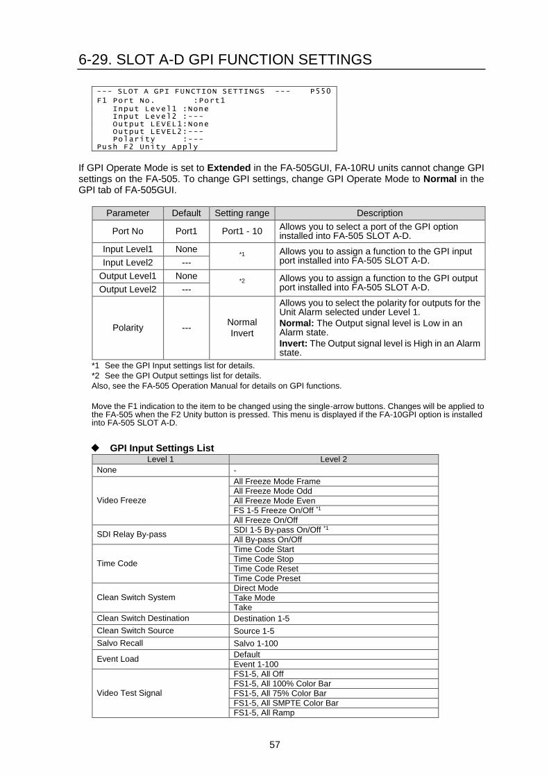
57
6-29. SLOT A-D GPI FUNCTION SETTINGS
--- SLOT A GPI FUNCTION SETTINGS --- P550
F1 Port No. :Port1 Input Level1 :None Input Level2 :--- Output LEVEL1:None Output LEVEL2:--- Polarity :--- Push F2 Unity Apply
If GPI Operate Mode is set to Extended in the FA-505GUI, FA-10RU units cannot change GPI settings on the FA-505. To change GPI settings, change GPI Operate Mode to Normal in the GPI tab of FA-505GUI.
Parameter Default Setting range Description
Port No Port1 Port1 - 10 Allows you to select a port of the GPI option installed into FA-505 SLOT A-D.
Input Level1 None *1 Allows you to assign a function to the GPI input
port installed into FA-505 SLOT A-D. Input Level2 ---
Output Level1 None *2 Allows you to assign a function to the GPI output
port installed into FA-505 SLOT A-D. Output Level2 ---
Polarity --- Normal
Invert
Allows you to select the polarity for outputs for the Unit Alarm selected under Level 1.
Normal: The Output signal level is Low in an Alarm state.
Invert: The Output signal level is High in an Alarm state.
*1 See the GPI Input settings list for details.
*2 See the GPI Output settings list for details.
Also, see the FA-505 Operation Manual for details on GPI functions.
Move the F1 indication to the item to be changed using the single-arrow buttons. Changes will be applied to the FA-505 when the F2 Unity button is pressed. This menu is displayed if the FA-10GPI option is installed into FA-505 SLOT A-D.
GPI Input Settings List Level 1 Level 2
None -
Video Freeze
All Freeze Mode Frame All Freeze Mode Odd
All Freeze Mode Even FS 1-5 Freeze On/Off *1
All Freeze On/Off
SDI Relay By-pass SDI 1-5 By-pass On/Off *1
All By-pass On/Off
Time Code
Time Code Start
Time Code Stop Time Code Reset
Time Code Preset
Clean Switch System Direct Mode
Take Mode Take
Clean Switch Destination Destination 1-5
Clean Switch Source Source 1-5
Salvo Recall Salvo 1-100
Event Load Default
Event 1-100
Video Test Signal
FS1-5, All Off
FS1-5, All 100% Color Bar FS1-5, All 75% Color Bar
FS1-5, All SMPTE Color Bar FS1-5, All Ramp

58
Audio Test Signal FS1-5, AES A-D, Analog, All Off *2, *3 FS1-5 AES A-D, Analog, All 500Hz Tone *2, *3
FS1-5 AES A-D, Analog, All 1kHz Tone *2, *3
Other GPI Lock
*1 Displays an “*” at the beginning of text strings if the function is ineffective due to other settings.
*2 AES A-D functions are displayed if the FA-10AES-BL/UBL/UBLC option is installed in the corresponding SLOT A-D.
*3 Analog audio functions are displayed if the FA-10ANA-AUD option is installed in Slot D.
GPI Output Settings List
Level 1 Level 2
None -
Unit Alarm
FAN 1/2/3/4 Alarm
FAN 1-4 Alarm
DC Power 1/2 *1
DC Power 1-2 *1
Any Alarm
Video In FS 1-5 Video In
Reference In
Audio In FS 1-5 Audio In
OP A-D Audio In *2
Other Input Function *3
*1 DC Power 2 is displayed if the FA-10PS option is installed.
*2 OP A-D Audio In is displayed if the FA-10AES-BL/UBL/UBLC/ANA-AUD option is installed into SLOT A-D.
*3 The output function varies depending on the Input setting of the port. Refer to the “Input Function Operation Characteristics of GPI Output” for details.
Input Function Operation Characteristics of GPI Output
Input setting Output Behavior (under Input Function)
All Freeze Frame Outputs when Freeze Mode is set to Frame for all FSs 1-5.
All Freeze Odd Outputs when Freeze Mode is set to Odd for all FSs 1-5.
All Freeze Even Outputs when Freeze Mode is set to Even for all FSs 1-5.
FS 1-5 Freeze On/Off Outputs when Freeze is set to On for the subject FS.
All Freeze On/Off Outputs when Freeze is set to On for all FSs 1-5.
SDI 1-5 By-pass On/Off Outputs when By-pass is set to On for the subject FS.
All By-pass On/Off Outputs when By-pass is set to On for all FSs 1-5.
Time Code Start Outputs when Time Code Starts.
Time Code Stop Outputs when Time Code Stops.
Time Code Reset No action.
Time Code Preset No action.
Direct Mode Outputs when Clean Switch is set to Direct Mode.
Take Mode Outputs when Clean Switch is set to Take Mode.
Take Outputs and does not output alternately when a Source is selected for a Destination in Take Mode so that Clean Switch is in the Take stand-by state.
Destination 1-5 Outputs when the subject Destination is selected.
Source 1-5 Outputs when the subject Source is selected.
Salvo 1-100 No action.
Event Load Default Outputs and does not output alternately for about 3 seconds when an Event Load is performed.
Event 1-100 Outputs and does not output alternately for about 3 seconds when an Event Load is performed.
Video Test Signal FS1-5 Off
Outputs when Video Test Signal is set to Off for the subject FS.
Video Test Signal FS1-5 100% Color Bar
Outputs when Video Test Signal is set to 100% Color Bar for the subject FS.

59
Video Test Signal FS1-5 SMPTE Color Bar
Outputs when Video Test Signal is set to SMPTE Color Bar for the subject FS.
Video Test Signal FS1-5 Ramp
Outputs when Video Test Signal is set to RAMP for the subject FS.
Video Test Signal All Off Outputs when Video Test Signal All is set to Off.
Video Test Signal All 100% Color Bar
Outputs when Video Test Signal All is set to 100% Color Bar.
Video Test Signal All SMPTE Color Bar
Outputs when Video Test Signal All is set to SMPTE Color Bar.
Video Test Signal All Ramp Outputs when Video Test Signal All is set to RAMP.
Audio Test Signal FS1-5 Off
Outputs when Audio Test Signal is set to Off for the subject FS.
Audio Test Signal FS1-5 500Hz
Outputs when Audio Test Signal is set to 500Hz for the subject FS.
Audio Test Signal FS1-5 1kHz
Outputs when Audio Test Signal is set to 1kHz for the subject FS.
Audio Test Signal AES A-D Off
Outputs when Audio Test Signal is set to Off for the subject AES.
Audio Test Signal AES A-D 500Hz
Outputs when Audio Test Signal is set to 500Hz for the subject AES.
Audio Test Signal AES A-D 1kHz
Outputs when Audio Test Signal is set to 1kHz for the subject AES.
Audio Test Signal Analog Off
Outputs when Audio Test Signal is set to Off for the Analog audio.
Audio Test Signal Analog 500Hz
Outputs when Audio Test Signal is set to 500Hz for the Analog audio.
Audio Test Signal Analog 1kHz
Outputs when Audio Test Signal is set to 1kHz for the Analog audio.
Audio Test Signal All Off Outputs when Audio Test Signal All is set to Off.
Audio Test Signal All 500Hz Outputs when Audio Test Signal All is set to 500Hz.
Audio Test Signal All 1kHz Outputs when Audio Test Signal All is set to 1kHz.
GPI Lock Outputs when GPI Lock is enabled.
6-30. CLOSED CAPTION SETTINGS --- SDI MULTIPLEXER --- P556 F1 FS1 SD Caption:CEA-608CC(Lne21) FS2 SD Caption:CEA-608CC(Lne21) FS3 SD Caption:CEA-608CC(Lne21) FS4 SD Caption:CEA-608CC(Lne21) FS5 SD Caption:CEA-608CC(Lne21)
This menu helps you to detect Closed Caption ancillary data for extracting it from SDI inputs.
Parameter Default Setting range Description
FS1 to FS5
SD Caption : CEA-608
CC(Line21) CEA-608 CC(Line21)
ST334-1 CC
Allows you to select a closed caption standard for detecting closed caption in 525/60i SDI inputs.
To change the FS selection to set settings, refer to section 5-3-7. “Selecting 5-channel Frame Synchronizers.”
ANC
ANALOG9

60
6-31. AFD DETECT SETTINGS FS1 Name:FS 1 --- AFD DETECT SETTINGS --- P557 F1 SD SDI:S2016-3 AFD VI(525/60) F1:Line14 F2:Line277 VI(625/60) F1:Line11 F2:Line324 WSS(625/60) F1:Line23
This menu helps you to detect AFD ancillary data for extracting it from SDI inputs.
Parameter Default Setting range Description
SD SDI S2016-3 AFD
S2016-3 AFD
RP 186 VI
BT1119-2 WSS
Allows you to select an AFD standard for detecting AFD data.
VI(525/60) F1 Line14 Line12 to 19
Specify the line(s) in which AFD data is embedded.
Use F1 for the line in Field 1 and F2 for the line in Field2.
F2 Line277 Line275 to 282
VI(625/50) F1 Line11 Line8 to 22
F2 Line324 Line321 to 335
WSS(625/50) F1 Line23 Line8 to 23
To change the FS selection to set settings, refer to section 5-3-7. “Selecting 5-channel Frame Synchronizers.”
6-32. AFD LOSS SETTINGS FS1 Name:FS 1 --- AFD DETECT SETTINGS --- P558 F1 S2016-3(SD) :Remove S2016-3(HD) :Remove RP186 VI(SD):Remove WSS(SD) :Remove
This menu allows you to specify an aspect-ratio processing for use if AFD data cannot be detected.
Parameter Default Setting range Description
S2016-3(SD) Remove
Remove Hold
4:3 L 16:9 T 4:3 L 14:9 T 4:3 L>16:9 4:3 F 4:3
4:3 L 16:9 PRTD 4:3 L 14:9
4:3 F ALT 14:9 4:3 L ALT 14:9 4:3 L ALT 4:3 16:9 L>16:9 16:9 F 16:9 16:9 P 4:3
16:9 F PRTD 16:9 P 14:9
16:9 P ALT 14:9 16:9 F ALT 14:9 16:9 F ALT 4:3
Select an AFD code if S2016-3 data cannot be detected in SD-SDI inputs.
The selected AFD code is used for conversion process.
Remove: If the automatic aspect ratio processing is enabled in the built-in converter (FA-505UD), 4:3 F 4:3 is applied. But no S2016-3 AFD data is embedded in SDI outputs.
ANC
ANALOG9
ANC
ANALOG9

61
S2016-3(HD) Remove
Remove Hold
16:9 L>16:9 16:9 F 16:9 16:9 P 4:3
16:9 F PRTD 16:9 P 14:9
16:9 P ALT 14:9 16:9 F ALT 14:9 16:9 F ALT 4:3
Select an AFD code if S2016-3 data cannot be detected in HD-SDI inputs.
The selected AFD code is used for conversion process.
Remove: If the automatic aspect ratio processing is enabled in the built-in converter (FA-505UD), 16:9 F 16:9 is applied. But no S2016-3 AFD data is embedded in SDI outputs.
RP186 VI(SD) Remove
Remove Hold
4:3 L 16:9 T 4:3 L 14:9 T 4:3 L>16:9 4:3 F 4:3
4:3 L 16:9 PRTD 4:3 L 14:9
4:3 F ALT 14:9 4:3 L ALT 14:9 4:3 L ALT 4:3 16:9 L>16:9 16:9 F 16:9 16:9 P 4:3
16:9 F PRTD 16:9 P 14:9
16:9 P ALT 14:9 16:9 F ALT 14:9 16:9 F ALT 4:3
Select an AFD code if RP186 VI data cannot be detected in SD-SDI inputs.
The selected AFD code is used for conversion process.
Remove: If the automatic aspect ratio processing is enabled in the built-in converter (FA-505UD), 4:3 F 4:3 is applied. But no VI AFD data is embedded in SDI outputs.
WSS(SD) Remove
Remove Hold
4:3 BOX 16:9 T 4:3 BOX 14:9 T 4:3 BOX>16:9 C
4:3 F 4:3 4:3 BOX 4:3 C 4:3 BOX 16:9 C
4:3 F 14:9 16:9 F 16:9 Anamorphic
Select an AFD code if BT1119-2 WSS data cannot be detected in SD-SDI inputs.
The selected AFD code is used for conversion process.
Remove: If the automatic aspect ratio processing is enabled in the built-in converter (FA-505UD), 4:3 F 4:3 is applied. But no WSS AFD data is embedded in SDI outputs.
6-33. TIMECODE DETECT SETTINGS FS1 Name:FS 1 --- TIMECODE DETECT SETTINGS --- P559 S12M-1 VITC SETTINGS F1-F2 VITC(525/60) F1:Line14 F2:Line277 VITC(625/50) F1:Line19 F2:Line332
This menu helps you to detect Timecode ancillary data for extracting it from SDI inputs.
Parameter Default Setting range Description
VITC(525/60)
F1 Line14 Line12 to 19
Specify the line(s) in which AFD data is embedded.
Use F1 for the line in Field 1 and F2 for the line in Field2.
F2 Line277 Line275 to 282
VITC(625/50)
F1 Line19 Line8 to 22
F2 Line332 Line321 to 335
ANC
ANALOG9

62
6-34. INPUT ANCILLARY STATUS 1 FS1 Name:FS 1 --- INPUT ANCILLARY STATUS1 --- P561 Standard Status Line CEA-608 :--- --- Video Index:--- --- WSS :--- ---
This menu displays the input ancillary data status for each FS. To change an FS to be monitored, refer to section 5-3-7. “Selecting 5-channel Frame Synchronizers.”
6-35. INPUT ANCILLARY STATUS 2 FS1 Name:FS 1 --- INPUT ANCILLARY STATUS2 --- P562 No,DID,SDID, Standard ,Line No 1:--- ,--- , ---- ,---- 2:--- ,--- , ---- ,---- 3:--- ,--- , ---- ,---- 4:--- ,--- , ---- ,---- 5:--- ,--- , ---- ,----
This menu displays input ancillary data packets by their Data ID number. Move up and down pages (No1 to 50) by using the single-arrow buttons. Up to 48 ancillary data packets can be displayed. To change an FS to be monitored, refer to section 5-3-7. “Selecting 5-channel Frame Synchronizers.”
6-36. SDI MULTIPLEXER
This menu allows you to select ancillary data output mode for each FS. Refer to Sec 4-2-3. “SDI Multiplexer” in “FA-505 Operation Manual.”
--- SDI MULTIPLEXER --- P564 F1-F3 FS1 Mode:H/V H:Overwrite V:Pass FS2 Mode:H/V H:Overwrite V:Pass FS3 Mode:H/V H:Overwrite V:Pass FS4 Mode:H/V H:Overwrite V:Pass FS5 Mode:H/V H:Overwrite V:Pass
Parameter Default Setting range Description
FS1 to FS5
Mode H/V
H/V
Detail
Allows you to select a processing mode for ancillary data for each FS.
H/V: Allows you to select overwrite, pass or blank the HANC and VANC spaces on output signals.
Detail: Deletes all exiting H/V ANC data sources from SDI inputs and embeds the processed data or new audio or other sources into SDI output.
H Overwrite
Overwrite
Pass
Blank
If H/V is selected for ANC Mode, select a processing type for the HANC space (mainly audio) on SDI output.
Overwrite: Removes the embedded HANC data from input signals, then embeds the processed data or new audio or other sources into output signals. Other data than audio is inserted after audio data.
Pass: Passes through the HANC data space ” as is” without processing and allows to pass or delete each audio group in the Embedded Audio menu (see sec. 6-37).
Blank: Blanks all HANC data space except audio sources. (Audio is passed through from SDI output.)
ANC
ANALOG9
ANC
ANALOG9
ANC
ANALOG9

63
V Overwrite Pass
Blank
Select a processing type for the VANC space on SDI output.
Pass: Passes through the VANC data space ”as is.”
Blank: Blanks all VANC data space.
6-37. EMBEDDED AUDIO MULTIPLEXER
FS1 Name:FS 1
--- EMBEDDED AUDIO MULTIPLEXER --- P565
F1 Group1:Enable
F2 Group2:Enable
F3 Group3:Enable
F4 Group4:Enable
Parameter Default Setting range Description
Group1 to
Group4 Enable
Disable
Enable
Allows you to select or unselect each Embedded Audio Group to enable or disable embedded audio insertion.
To change an FS to be monitored, refer to section 5-3-7. “Selecting 5-channel Frame Synchronizers.”
6-38. CLOSED CAPTION EMBEDDED FS1 Name:FS 1 --- CLOSED CAPTION EMBEDDED --- P566 CEA608 525/60 Line21/284 F1 EMB:Disable S334-1 525/60 Line12/275 F1 EMB:Disable CEA708 1080i/PsF Line9 EMB:Disable CEA708 720p Line9 EMB:Disable CEA708 3G-LevelA Line9 EMB:Disable CEA708 3G-LevelB Line9 EMB:Disable
This menu allows you to specify the line(s) for embedding Closed Caption data onto SDI output. This page is enabled only when ANC Mode (P564) is set to Detail.
Parameter Default Setting range Description
CEA605(525/60) Line Line21/284 -
To embed data source, set EMB to Enable.
Specify the line(s) within the setting range for each format.
EMB Disable Disable, Enable
S334-1(525/60) Line Line12/275 Line12/275-19/282
EMB Disable Disable, Enable
CEA708(1080i/PsF) Line Line9 Line9 to 20
EMB Disable Disable, Enable
CEA708(720p) Line Line9 Line9 to 25
EMB Disable Disable, Enable
CEA708(3G Level-A) Line Line9 Line9 to 25
EMB Disable Disable, Enable
CEA708(3G Level-B) Line Line9 Line9 to 41
EMB Disable Disable, Enable
To change an FS to be monitored, refer to section 5-3-7. “Selecting 5-channel Frame Synchronizers.”
ANC
ANALOG9
ANC
ANALOG9

64
6-39. S2016-3 AFD EMBEDDED FS1 Name:FS 1 --- S2016-3 AFD EMBEDDED --- P567 525/60 F1:Line12/275 F2 EMB:Disable 625/50 F1:Line8/321 F2 EMB:Disable 1080i/PsF F1:Line9/571 F2 EMB:Disable 720p F1:Line9 F2 EMB:Disable 3G-LevelA F1:Line9 F2 EMB:Disable 3G-LevelB F1:Line9/571 F2 EMB:Disable
This menu allows you to specify the line(s) for embedding S2016-3 AFD data onto SDI output. This page is enabled only when ANC Mode (P564) is set to Detail.
Parameter Default Setting range Description
525/60 Line 12/275 12/275 to 19/282
To embed data source, set EMB to Enable.
Specify the line(s) within the setting range for each format.
Embedded Disable Disable, Enable
625/50 Line 8/321 8/321 to 22/335
Embedded Disable Disable, Enable
1080i/PsF Line 9/571 9/571 to 20/582
Embedded Disable Disable, Enable
720p Line 9 9 to 25
Embedded Disable Disable, Enable
3G Level-A Line 9 9 to 41
Embedded Disable Disable, Enable
3G Level-B Line 9/571 9/571 to 20/582
Embedded Disable Disable, Enable
To change an FS to be monitored, refer to section 5-3-7. “Selecting 5-channel Frame Synchronizers.”
6-40. RP186 VI AFD EMBEDDED FS1 Name:FS 1 --- RP186 VI AFD EMBEDDED --- P568 525/60 F1 Field1:Line14 F2 Field2:Line277 525/60 Embedded:Disable 625/50 F1 Field1:Line11 F2 Field2:Line324 625/50 Embedded:Disable
This menu allows you to specify the line(s) for embedding RP186 VI AFD data onto SDI output. This page is enabled only when ANC Mode (P564) is set to Detail.
Parameter Default Setting range Description
525/60
Field1 Line14 Line12 to 19
To embed data source, set EMB to Enable.
Specify the line(s) within the setting range for each format.
Field2 Line277 Line275 to 282
Embedded Disable Disable, Enable
625/50
Field1 Line11 Line8 to 22
Field2 Line324 Line321 to 335
Embedded Disable Disable, Enable
To change the FS selection to set settings, refer to section 5-3-7. “Selecting 5-channel Frame Synchronizers.”
ANC
ANALOG9
ANC
ANALOG9
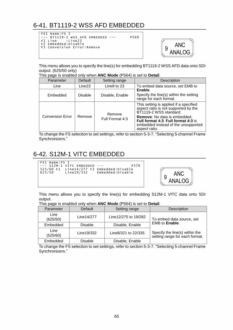
65
6-41. BT1119-2 WSS AFD EMBEDDED FS1 Name:FS 1 --- BT1119-2 WSS AFD EMBEDDED --- P569 F1 Line :Line23 F2 Embedded:Disable F3 Conversion Error:Remove
This menu allows you to specify the line(s) for embedding BT1119-2 WSS AFD data onto SDI output. (625/50 only) This page is enabled only when ANC Mode (P564) is set to Detail.
Parameter Default Setting range Description
Line Line23 Line8 to 23 To embed data source, set EMB to Enable.
Specify the line(s) within the setting range for each format.
Embedded Disable Disable, Enable
Conversion Error Remove Remove
Full Format 4:3
This setting is applied if a specified aspect ratio is not supported by the BT1119-2 WSS standard:
Remove: No data is embedded. Full format 4:3: Full format 4:3 is embedded instead of the unsupported aspect ratio.
To change the FS selection to set settings, refer to section 5-3-7. “Selecting 5-channel Frame Synchronizers.”
6-42. S12M-1 VITC EMBEDDED FS1 Name:FS 1 --- S12M-1 VITC EMBEDDED --- P570 525/60 F1 Line14/277 F2 Embedded:Disable 625/50 Line19/332 Embedded:Disable
This menu allows you to specify the line(s) for embedding S12M-1 VITC data onto SDI output. This page is enabled only when ANC Mode (P564) is set to Detail.
Parameter Default Setting range Description
Line
(625/50) Line14/277 Line12/275 to 19/282
To embed data source, set EMB to Enable.
Specify the line(s) within the setting range for each format.
Embedded Disable Disable, Enable
Line
(525/60) Line19/332 Line8/321 to 22/335
Embedded Disable Disable, Enable
To change the FS selection to set settings, refer to section 5-3-7. “Selecting 5-channel Frame Synchronizers.”
ANC
ANALOG9
ANC
ANALOG9

66
6-43. S12M-1 ATC VITC EMBEDDED FS1 Name:FS 1 --- S12M-1 ATC VITC EMBEDDED --- P571 525/60 F1:Line12/275 EMB:Disable 625/50 Line8/321 EMB:Disable 1080i/PsF Line9/571 EMB:Disable 720p Line9 EMB:Disable 3G-LevelA Line9 EMB:Disable 3G-LevelB Line9/571 EMB:Disable
This menu allows you to specify the line(s) for embedding S12M-1 ATC VITC data onto SDI output. This page is enabled only when ANC Mode (P564) is set to Detail.
Parameter Default Setting range Description
525/60 Line 12/275 12/275 to 19/282
To embed data source, set EMB to Enable.
Specify the line(s) within the setting range for each format.
Embedded Disable Disable, Enable
625/50 Line 8/321 8/321 to 22/335
Embedded Disable Disable, Enable
1080i/PsF Line 9/571 -
Embedded Disable Disable, Enable
720p Line 9 -
Embedded Disable Disable, Enable
3G-LevelA Line 9 -
Embedded Disable Disable, Enable
3G-LevelB Line 9/571 -
Embedded Disable Disable, Enable
To change the FS selection to set settings, refer to section 5-3-7. “Selecting 5-channel Frame Synchronizers.”
6-44. S12M-1 ATC LTC EMBEDDED FS1 Name:FS 1 --- S12M-1 ATC LTC EMBEDDED --- P572 525/60 F1:Line12 F2 Embedded:Disable 625/50 F1:Line8 F2 Embedded:Disable 1080i/PsF Line10 Embedded:Disable 720p Line10 Embedded:Disable 3G-LevelA Line10 Embedded:Disable 3G-LevelB Line10 Embedded:Disable
This menu allows you to specify the line(s) for embedding S12M-1 ATC LTC data onto SDI output. This page is enabled only when ANC Mode (P564) is set to Detail.
Parameter Default Setting range Description
525/60 Line 12 12 to 19
To embed data source, set EMB to Enable.
Specify the line within the setting range for each format.
Embedded Disable Disable, Enable
625/50 Line 8 8 to 22
Embedded Disable Disable, Enable
1080i/PsF Line 10 -
Embedded Disable Disable, Enable
720p Line 10 -
Embedded Disable Disable, Enable
3G-LevelA Line 10 -
Embedded Disable Disable, Enable
3G-LevelB Line 10 -
Embedded Disable Disable, Enable
To change the FS selection to set settings, refer to section 5-3-7. “Selecting 5-channel Frame Synchronizers.”
ANC
ANALOG9
ANC
ANALOG9

67
6-45. EMBEDDED TIME CODE --- EMBEDDED TIME CODE --- P575 FS1 F1 VITC:ATC(VITC) F2 LTC:ATC(VITC) FS2 VITC:ATC(VITC) LTC:ATC(VITC) FS3 VITC:ATC(VITC) LTC:ATC(VITC) FS4 VITC:ATC(VITC) LTC:ATC(VITC) FS5 VITC:ATC(VITC) LTC:ATC(VITC)
LTC Port:Input Time 00:00:00:00
This menu allows you to specify a timecode source for VITC and/or LTC to be embedded in SDI output for each FS.
Parameter Default Setting range Description
FS1- FS5
VITC ATC(VITC)
ATC(VITC) ATC(LTC)
DVITC LTC In TCG
ATC(VITC): Timecode embedded in the SDI input (S12M-1 ATC (VITC))
ATC(LTC): Timecode embedded in the SDI input (S12M-1 ATC (LTC))
DVITC: Timecode embedded in the SDI input (S12M-VITC) * SD signals only
LTC In: Timecode input from LTC In on the rear panel.
TCG: Internally generated timecode. Use Timecode Generator menu to generate a new timecode.
LTC ATC(LTC) (Same as
above) (Same as above)
LTC Port Input Input
Output
Allows you to configure the LTC IN/OUT connector on the rear panel as an input or output.
Time - -
If LTC Port is set to Input, the current status of timecode input to the connector is displayed.
If LTC Port is set to Output, the counter of the built-in Timecode Generator is displayed.
Move the F1/F2 indication to the item to be changed using the single-arrow buttons.
6-46. TIMECODE GENERATOR --- TIMECODE GENERATOR --- P576 Time 00:00:00:00 F1 Start,F2 Stop,F3 Reset F4 Preset Preset Time 0: 0: 0: 0 Drop Frame:Off
This menu allows you to generate a timecode to be embedded onto SDI outputs. Select TCG in the EMBEDDED TIME CODE menu. Use the following four buttons to generate a new timecode.
Start (F1 Unity button) Stop (F2 Unity button) Reset (F3 Unity button) Preset (F4 Unity button)
Parameter Default Setting range Description
Preset Time 0 - Sets the Preset Time using F1 (hour), F2 (minute), F3 (second) and F4 (frame).
Drop Frame Off Off
On Allows you to select Drop frame timecode (On) or Non-drop frame timecode (Off).
Move the F1/F2 indication to the item to be changed using the single-arrow buttons.
ANC
ANALOG9
ANC
ANALOG9

68
6-47. VIDEO INPUT LOSS MODE --- VIDEO INPUT LOSS MODE --- P578 F1 FS1:Black FS2:Black FS3:Black FS4:Black FS5:Black
Parameter Default Setting range Description
FS1 - FS5 Black
Black Blue Red
Magenta Green Cyan
Yellow
Color Bar
Auto Freeze
Out Disable
Allows you to select an operation for the time the video signal input disappears for each FS.
Black – Yellow: Outputs the selected back color.
Color Bar: Outputs the SMPTE color bar.
Auto Freeze: Continues to output the image from one frame before the input signal loss.
Out Disable: No signal output. (Sets the output video signal to high impedance.)
To change the FS selection to set settings, refer to section 5-3-7. “Selecting 5-channel Frame Synchronizers.”
6-48. FS MODE SETTINGS FS2 Name:FS 2 --- FS MODE SETTINGS --- P579 F1 Sync Mode :Frame
Frame Delay :Off 3G Out Payload ID :Overwrite 4KFS(FS2-5) :Enable 4k Input Mode :Auto
2SI Out Payload ID:2SI
Parameter Default Setting range Description
Sync Mode Frame
Frame
Line
AVDL
Line(Minimum)
Frame: Adjusts horizontal and vertical timings of signals based on the adjusted FA-505 system phases. Effective on both synchronous and asynchronous signals.
Line/AVDL/Line(Minimum): Adjusts horizontal and vertical timings of signals listed in the “Adjustable range per signal format” table on page 70, based on the adjusted FA-505 system phases.
Frame Delay Off Off
1 to 8 Frames
Allows you to set the amount of Frame Delay for each FS.
Displays Unadjustable if Sync Mode is not set to Frame.
3G Out Payload ID
*1, *4
Overwrite Overwrite
Pass
Allows you to select which Payload ID is inserted into G SDI output. (See Sec.6-57. Payload ID Input Status.)
Overwrite: Inserts a new Payload ID that matches to the output signal of 3G Level-A, 1080/59p(50p) Level-B or 2x1080/59i(50i) Level B, according to input signal and settings.
Pass: Inserts the Payload ID of input signal.
10 SYSTEM
10 SYSTEM

69
4KFS
(FS2-FS5 only)
*3
Disable Enable
Disable
Allows you to enable/disable 4KFS mode.
4 input signals are simultaneously phase-adjusted within 2 lines (1 line for Level B) for horizontal and 1 frame for vertical timings.
Enable: Processes the FS2, FS3, FS4 and FS5 video signals as a 4K video. Purple light indicates 4KFS mode is active.
Frame dropping and repeating may occur in 4K video because these four signals are processed as synchronous video even if they are not synched with the genlock signal. To avoid this problem, set as below for FS2 to FS5.
-Set Sync Mode to Frame.
-Set System Phase to the same settings for FS2-FS5.
Disable: Processes the FS2, FS3, FS4 and FS5 signals independently.
4k Input Mode
*2, *4
Auto
Auto
SQD
2SI
Selects a method for determining SQD or 2SI using 4K input signal payload ID codes.
Auto: Detects input signal payload ID codes to determine SQD or 2SI.
SQD: Regards 4K input as SQD.
2SI: Regards 4K input as 2SI.
When 2SI is selected, an error will be indicated by the 0 STATUS flashing if an FS channel (FS2-FS5) has no 2SI identification code, or 2SI channel correspondence is mismatched between Payload ID and FS channel information. See Sec. 6-57 “PAYLOAD ID INPUT STATUS” for details on errors.
4k Output Mode
*2, *4
2SI 2SI
SQD
Selects SQD or 2SI to be embedded as Payload ID onto the SDI output stream in 4KFS mode.
SQD: Embeds payload ID codes for 3G-SDI.
2SI: Embeds payload ID codes for 2SI.
To change the FS selection to set settings, refer to section 5-3-7. “Selecting 5-channel Frame Synchronizers.” *1 Unavailable if FA-505 software version is 1.01 or earlier. *2 Available if 4KFS mode is enabled on the selected FS.
Unavailable if FA-505 software version is 1.21 or earlier. *3 If FA-505 software version is 1.01 or earlier, the 4KFS group is set to FS1-4.
If FA-505 software version is 1.10 or higher, the 4KFS group is set to FS2-5 *4 Available when video signals output in 3G format. Discarded in other formats.

70
<Adjustable range per signal format>
Format Adjustable range
Line AVDL Line (Minimum)
1080/59i, 1080/29p -1.5H to -0.5H -6H to -0.5H -1.3H to -0.3 H (-700 clk)
1080/30p -1.5H to -0.5H -6H to -0.5H -1.3H to -0.3 H (-700 clk)
720/59p -1.5H to -0.5H -6H to -0.5H -1.4H to -0.4 H (-700 clk)
1080/59p Level-A -1.5H to -0.5H -6H to -0.5H -1.3H to -0.3 H (-700 clk)
1050/50i, 1080/25p -1.5H to -0.5H -6H to -0.5H -1.25H to -0.25 H (-700 clk)
720/50p -1.5H to -0.5H -6H to -0.5H -1.35H to -0.35 H (-700 clk)
1080/50p Level-A -1.5H to -0.5H -6H to -0.5H -1.25H to -0.25 H (-700 clk)
1080/60p Level-A -1.5H to -0.5H -6H to -0.5H -1.3H to -0.3 H (-700 clk)
1080/23.98PsF, 1080/23.98p -1.5H to -0.5H -6H to -0.5H -1.25H to -0.25 H (-700 clk)
1080/24PsF, 1080/24p -1.5H to -0.5H -6H to -0.5H -1.25H to -0.25 H (-700 clk)
1080/59p Level-B -3.0H to -1.0H -11H to -1.0H -1.3H to -0.3 H (-700 clk)
Level-B output with converter -4H to -3H -11H to -3H -3.3H to -2.3 H (-2H -700 clk)
Other format output with converter -1.5H to -0.5H -6H to -0.5H -1.3H to -0.3 H (-700 clk)
1080/50p Level-B -3.0H to -1.0H -11H to -1.0H -1.25H to -0.25 H (-700 clk)
Level-B output with converter -4H to -3H -11H to -3H -3.25H to -2.25 H (-2H -700 clk)
Other format output with converter -1.5H to -0.5H -6H to -0.5H -1.25H to -0.25 H (-700 clk)
2x1080/59i Level-B -3H to -1H -11H to -1H -1.3H to -0.3 H (-700 clk)
2x1080/50i Level-B -3H to -1H -11H to -1H -1.25H to -0.25 H (-700 clk)
1080/59p Level-A→B -3.5H to -2.5H -8H to -2.5H -3.3H to -2.3 H (-2H -700 clk)
1080/50p Level-A→B -3.5H to -2.5H -8H to -2.5H -3.243H to -2.43 H (-2H -1150 clk)
1080/59p Level-B→A -1.5H to -0.5H -6H to -0.5H -1.3H to -0.3 H (-700 clk)
1080/50p Level-B→A -1.5H to -0.5H -6H to -0.5H -1.25H to -0.25 H (-700 clk)
525/60 -1.5H to -0.5H -6H to -0.5H -1.4H to -0.4 H (-700 clk)
625/50 -1.5H to -0.5H -6H to -0.5H -1.4H to -0.4 H (-700 clk)
IMPORTANT
Note that 1080/59p or 1080/50p Level B output signal that is converted from Level A requires more delay than other output signal formats. In such case, 3H delay is present in Line or AVDL Sync Mode, and 2H+700clk or 2H+1150clk in Line (Minimum) Sync mode.
6-49. VIDEO SYSTEM PHASE/POSITION FS1 Name:FS 1 --- VIDEO SYSTEM PHASE/POSITION --- P580 F1 Horizontal Phase : 0 Clock F2 Vertical Phase : 0 Line F3 Horizontal Position: 0 Pixel F4 Vertical Position: 0 Line REF:525/60 Synchronous is Frame mode
Parameter Default Setting range (Steps) Description
Horizontal Phase
0 *1 ± 1400 (1 Clock) Allows you to adjust the horizontal and vertical phases of the system referring to genlock signal.
Vertical
Phase 0 *1 ± 600 (1 Line)
Horizontal Position
0 ± 200 (HD 2 Pixel)
± 200 (SD 4 Pixel) Adjusts the horizontal/vertical position of output videos. Vertical
Position 0 ± 100 (1 Line)
* An “Unadjustable” message is displayed and the settings disabled, if no reference signal input is present.
*1 If FA-505 Software Version is 2.12 or earlier, Horizontal/Vertical Phase default values vary depending on the Sync Mode and 3G Level-A/B settings. In such cases, refer to tables on next page.
10 SYSTEM

71
To change the FS selection to set settings, refer to section 5-3-7. “Selecting 5-channel Frame Synchronizers.” The sync mode of the FS is displayed in the bottom line.
Horizontal Phase Default Values (Ver 2.12 or eariler)
Sync Mode Default
Frame 0
Line 0
AVDL 0
Line(Minimum) 700
Line(Minimum)[1080/50p LevelA to 1080/50p LevelB conversion] 1150
Vertical Phase Default Values (Ver 2.12 or eariler)
Sync Mode Default
Frame 0
Line 1
Line [3G LevelA to 1080/50p LevelB conversion] 3
AVDL 1
AVDL [3G LevelA to 1080/50p LevelB conversion] 3
Line(Minimum) 0
Line(Minimum) [3G LevelA to 1080/50p LevelB conversion] 2
6-50. VIDEO FREEZE FS1 Name:FS 1 --- VIDEO FREEZE --- P582 F1 Freeze On/Off:Off F2 Freeze Mode :Frame F3 Strobe Freeze:Off F4 All FS Freeze:Off Input Video:1080/59i
Parameter Default Setting range Description
Freeze Off Off, On Allows you to turn Freeze On/Off for each FS.
Freeze Mode Frame Frame Odd Even
Allows you to select an operation mode for Freeze.
Displays “Unadjustable”, if no signal or a progressive signal is input to the FS.
Strobe Freeze Off Off
1 - 255
Allows you to set the interval to refresh the images by the number of fields for the field or frame freeze.
Off: Images will not be refreshed.
All FS Freeze Off On
Off
Allows you to turn Freeze On/Off for all FSs 1-5. Freeze mode for each FS varies depending on the respective Freeze Mode settings.
Input Video - - Displays the input video format of the FS.
To change the FS selection to set settings, refer to section 5-3-7. “Selecting 5-channel Frame Synchronizers.”
10 SYSTEM

72
6-51. SD TV LINE MASK FS1 Name:FS 1 --- SD TV LINE MASK --- P583 F1-F4 L6 :Off L7 :Off L8 :Off L9 :Off
L10:Off L11:Off L12:Off L13:Off L14:Off L15:Off L16:Off L17:Off L18:Off L19:Off L20:Off L21:Off L22:Off L23:Off
Parameter Default Setting range Description
L6-23
(Line6 – 23) Off
Off
On
Allows you to set whether to mask the line for line 6 - 23 of SD-SDI signals in each FS.
Off: Outputs the signal without processing.
On: Masks the selected SD-SDI output signal line.
Move the F1/F2/F3/F4 indication to the item to be changed using the single-arrow buttons. To change the FS selection to set settings, refer to section 5-3-7. “Selecting 5-channel Frame Synchronizers.”
6-52. 3G SDI OUTPUT LEVEL --- 3G SDI OUTPUT LEVEL --- P584 F1 FS1:Follow Input
FS2:Follow Input FS3:Follow Input FS4:Follow Input FS5:Follow Input
Parameter Default Setting range Description
FS1 - FS5 Follow Input
Follow Input
Level A
Level B*
Allows you to select a 3G Level (Level A / B) for each FS.
Follow Input:
The 3G-SDI input signal Level will not be changed and output level will be the same.
Follow Input converts video to 3G Level A if it is other format than 3G Level B.
Level A:
Always outputs 3G-SDI Level A signals.
* If input signal is 3G-SDI Level B, the signal will automatically be converted to 3G-SDI Level A.
Level B:
Always outputs 3G-SDI Level B signals.
* If input signal is 3G-SDI Level A, the signal will automatically be converted to 3G-SDI Level B.
* Conversions are unavailable for 1080/60p (Level-A) signals. Move the F1/F2 indication to the item of which setting to be changed using the single-arrow buttons.
10 SYSTEM
10 SYSTEM

73
6-53. VIDEO TEST SIGNAL --- VIDEO TEST SIGNAL --- P585 F1 FS1:Off FS2:Off FS3:Off FS4:Off FS5:Off FS1-FS5:Off
Parameter Default Setting range Description
FS1-FS5 Off
Off Full CB 75% CB
SMPTE CB Ramp
Allows you to set each FS to generate the selected video test signal.
(Effective when FS1-FS5 is set to Off.)
FS1-FS5 Off
Off Full CB 75% CB
SMPTE CB Ramp
Allows you to set all FSs to generate the selected video test signal.
* Different video test signals cannot be set for each FS, unless FS1-FS5 is set to Off. Move the F1/F2 indication to the item to be changed using the single-arrow buttons.
6-54. VIDEO SYSTEM FRAME RATE --- VIDEO SYSTEM FRAME RATE --- P586 F1 Frame Rate:23.98/29.97/59.94 fps __________________________________________ | | |Carefully change “Frame Rate” | | | | | |__________________________________________
Parameter Default Setting range Description
Frame Rate
23.98/29.97/59.94 fps
23.98/29.97/59.94 fps
24/25/30/50/60 fps
Allows you to select a video system frame rate.
Note: Carefully adjust the setting to prevent the input/output video system settings from completely changing.
* A confirmation message appears regardless of the OPERATION SETTINGS menu (see sec. 6-22), Front Operation settings.
6-55. VIDEO INPUT STATUS --- VIDEO INPUT STATUS --- P591 FS1:525/60 FS2:1080/23PsF FS3:1080/59p LevelB FS4:Loss FS5:Loss REF:525/60
Parameter Default Setting range Description
FS1-FS5 - - Displays the input signal format for each FS, and the reference signal format.
STATUS0
10 SYSTEM

74
6-56. SDI VIDEO OUTPUT STATUS --- SDI VIDEO OUTPUT STATUS --- P593 SDI1a/1b:525/60 SDI2a/2b:1080/23PsF SDI3a/3b:1080/59p LevelA SDI4a/4b:1080/59i SDI5a/5b:1080/59i
Parameter Default Setting range Description
SDI1a/1b-SDI5a/5b - - Displays the output format for each SDI output connector.
6-57. PAYLOAD ID INPUT STATUS FS1 Name:FS 1 --- PAYLOAD ID INPUT STATUS --- P596 Byte : 1 / 2 / 3 / 4 |Check Sum LinkA: --- / --- / --- / --- | --- LinkB: --- / --- / --- / --- | ---
Payload ID and checksum values are 10-bit data (including parity bit) and displayed as three hexadecimal digits.
Display Input signal format Description
Link A
SD/HD No information display
3G Level A Displays the Payload ID embedded in Y signal.
3G Level B Displays the Payload ID embedded in Link A.
Link B
SD/HD No information display
3G Level A Displays the Payload ID embedded in C signal.
3G Level B Displays the Payload ID embedded in Link B.
* Unavailable if FA-505 software version is less than 1.01.
* Payload Identification Codes for 2SI are compliant to SMPTE ST425-5.
* In Auto mode, input signals are regarded as 2SI if a 2SI payload identification code is present in any channel (FS2 to FS5).
* Payload Identification Codes for 2SI are located in Byte 4 in the payload ID information. Payload Identification Codes for 3G-SDI Level-A are located in Bit [7..6] of Byte 4.
Bit[7..6]=0 3G-SDI Link1 Corresponds to FS2.
Bit[7..6]=1 3G-SDI Link2 Corresponds to FS3.
Bit[7..6]=2 3G-SDI Link3 Corresponds to FS4.
Bit[7..6]=3 3G-SDI Link4 Corresponds to FS5.
Payload Identification Code for 3G-SDI Level-B is located in Bit [7..5] of Byte 4.
Bit[7..5]=0 Data stream one on 3G-SDI Link1 Corresponds to FS2.
Bit[7..5]=1 Data stream two on 3G-SDI Link1 Corresponds to FS2.
Bit[7..5]=2 Data stream three on 3G-SDI Link2 Corresponds to FS3.
Bit[7..5]=3 Data stream four on 3G-SDI Link2 Corresponds to FS3.
Bit[7..5]=4 Data stream five on 3G-SDI Link3 Corresponds to FS4.
Bit[7..5]=5 Data stream six on 3G-SDI Link3 Corresponds to FS4.
Bit[7..5]=6 Data stream seven on 3G-SDI Link4 Corresponds to FS5.
Bit[7..5]=7 Data stream eight on 3G-SDI Link4 Corresponds to FS5.
* An error will be indicated by the 0 STATUS flashing if an FS channel (FS2-FS5) has no 2SI identification
code, or 2SI channel correspondence is mismatched between Payload ID and FS channel information when 2SI is selected for 4k Input Mode. For example, when an error occurred on FS2 and FS3, pressing the flashing 0 STATUS will display the message, “Detected Error: FS2 FS3.” If FS errors occur during menu operation, the following error messages will appear.
STATUS0
STATUS0

75
No Channel ID is present in the signal. Indicates that FS channel has no 2SI payload ID code.
Input signal and FS settings mismatched. Switch this input to FSX.
Indicates that 2SI channel correspondence is mismatched between Payload ID and FS channel information.
6-58. MAIN UNIT ALARM INFORMATION --- MAIN UNIT ALARM INFORMATION --- P601 FAN1:Normal FAN2:Normal FAN3:Normal FAN4:Normal DC POWER1:Normal* DC POWER2:Normal*
Parameter Default Setting range Description
FAN1 - FAN4 - -
Displays the FAN status of the connected FA-505.
Normal: All fans are operating normally.
Stopped: One or more fans have failed.
Power Off the unit and consult your reseller.
DC POWER1
DC POWER2 - -
Displays the status of Power Supply unit 1 and 2.
Normal: Power supply is normal.
Abnormal: A power failure has occurred. Power Off the unit and consult your reseller.
* No indication if an FA-505PS is not installed.
6-59. MAIN UNIT VERSION INFORMATION --- MAIN UNIT VERSION INFORMATION --- P602 FPGA1: 1.00 FPGA2: 1.00 FPGA3: 1.00 FPGA4: 1.00 FPGA5: 2.10 SOFT : 1.00 FA-505 Ser No.15780001
Parameter Default Setting range Description
FPGA1 - FPGA5
SOFT
Ser No.
- - Displays the software versions and serial number of the connected FA-505.
STATUS0
STATUS0

76
6-60. OPTION VERSION INFORMATION Slot(A) --- UNIT VERSION INFORMATION --- P603 Option Type:Not installed FPGA1:--.-- FPGA2:--.-- SOFT :--.--
Parameter Default Setting range Description
FPGA1 - FPGA2
SOFT - -
Displays version information for options installed in option slots A to D of the connected FA-505.
Slots A to D to be displayed can be selected with the same procedure as that to select FS 1 to 5.
6-61. OTHER OPTION INFORMATION --- UNIT VERSION INFORMATION --- P604 FA-505PS:Installed FA-505UD:Installed
Parameter Default Setting range Description
FA-505PS - - Displays whether the FA-505PS is installed or not.
FA-505UD - - Displays whether the FA-505UD is installed or not.
STATUS0
STATUS0
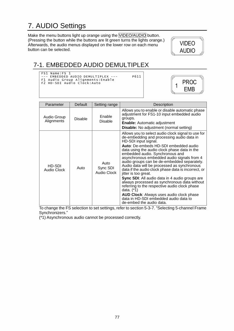
77
7. AUDIO Settings
Make the menu buttons light up orange using the VIDEO/AUDIO button. (Pressing the button while the buttons are lit green turns the lights orange.) Afterwards, the audio menus displayed on the lower row on each menu button can be selected.
7-1. EMBEDDED AUDIO DEMULTIPLEX FS1 Name:FS 1 --- EMBEDDED AUDIO DEMULTIPLEX --- P611 F1 Audio Group Alignments:Enable F2 HD-SDI Audio Clock:Auto
Parameter Default Setting range Description
Audio Group Alignments
Disable Enable
Disable
Allows you to enable or disable automatic phase adjustment for FS1-10 input embedded audio groups.
Enable: Automatic adjustment
Disable: No adjustment (normal setting)
HD-SDI Audio Clock
Auto
Auto
Sync SDI
Audio Clock
Allows you to select audio clock signal to use for de-embedding and processing audio data in HD-SDI input signal.
Auto: De-embeds HD-SDI embedded audio data using the audio clock phase data in the embedded audio. Synchronous and asynchronous embedded audio signals from 4 audio groups can be de-embedded separately. Audio data will be processed as synchronous data if the audio clock phase data is incorrect, or jitter is too great.
Sync SDI: All audio data in 4 audio groups are always processed as synchronous data without referring to the respective audio clock phase data. (*1)
AUD Clock: Always uses audio clock phase data in HD-SDI embedded audio data to de-embed the audio data.
To change the FS selection to set settings, refer to section 5-3-7. “Selecting 5-channel Frame Synchronizers.” (*1) Asynchronous audio cannot be processed correctly.
VIDEO
AUDIO
PROCEMB
1

78
7-2. EMBEDDED AUDIO ERROR SENSE --- EMBEDDED AUDIO ERROR SENSE --- P612 F1 FS1:Normal
FS2:Normal FS3:Normal FS4:Normal FS5:Normal
Parameter Default Setting range Description
FS1 - FS5 Normal
Disable
Normal
Sensitive
Allows you to select how to treat the audio error detected in each FS.
Disable: Disables mute function when change in audio status is detected. Normally not selected.
Normal: Mutes when a change on an SDI signal, ADP (Audio Data Packet), or DBN (Data Block Number) is detected.
Normally selected.
Sensitive: Mutes when a change on channel status, or EDP (Extended Data Packet) presence (only for SD-SDI), as well as the above items, is detected.
Move the F1/F2 indication to the item to be changed using the single-arrow buttons.
7-3. FADE IN/OUT --- FADE IN/OUT --- P613 F1 FS1:Disable
FS2:Disable FS3:Disable FS4:Disable FS5:Disable
Parameter Default Setting range Description
FS1 - FS5 Disable Disable
Enable
Disable: Always outputs input audio signals without adding any effect such as Fade or Mute.
Enable: Sets an audio to mute with fade out if an audio error is detected, and make it fade in when recovered.
Move the F1/F2 indication to the item to be changed using the single-arrow buttons.
PROCEMB
1
PROCEMB
1

79
7-4. EMBEDDED AUDIO MULTIPLEX FS1 Name:FS 1 --- EMBEDDED AUDIO MULTIPLEX --- P614 F1 Audio Group1:Auto F2 Audio Group2:Auto F3 Audio Group3:Auto F4 Audio Group4:Auto
Parameter Default Setting range Description
Audio Group 1
Auto
Auto Reference
Input CH 1/2 Input CH 3/4
Allows you to select an audio clock per group for SDI embedded audio output for each FS.
Auto: Automatically selects audio clock input in the NON-PCM signal channel, if an input NON-PCM signal is in the selected SDI embedded audio group. Automatically selects audio clock signal in the smallest numbered channel, if all signals in the audio group are NON-PCM. Automatically selects audio clock signal synchronized to the output video signal, if all signals in the audio group are PCM.
Reference: Uses an audio clock synchronized with the output video signal. (Used to synchronize audio with the video signals processed in the SRC.)
CH 1/2 - 15/16: An input audio clock in channels 1/2 to 15/16. An input audio clock in channels 1/2 to 15/16.
To output asynchronous audio signals, select one input channel pair for each group. For SD-SDI outputs, Reference clock is automatically selected regardless of the setting.
Audio Group 2
Auto
Auto Reference
Input CH 5/6 Input CH 7/8
Audio Group 3
Auto
Auto Reference
Input CH 9/10 Input CH 11/12
Audio Group 4
Auto
Auto Reference
Input CH 13/14 Input CH 15/16
To change the FS selection to set settings, refer to section 5-3-7. “Selecting 5-channel Frame Synchronizers.”
7-5. EMBEDDED AUDIO SRC MODE FS1 Name:FS 1 --- EMBEDDED AUDIO SRC MODE --- P616 F1 CH 1/2 :Auto F2 CH 3/4 :Auto
CH 5/6 :Auto CH 7/8 :Auto CH 9/10:Auto CH11/12:Auto CH13/14:Auto CH15/16:Auto
Parameter Default Setting range Description
CH1/2 - CH15/16
Auto
Auto
SRC In
By-pass
Allows you to the SRC circuit to pass or by-pass audio signals per channel pair for each FS.
Auto: Sets the SRC circuit to pass signals. However, NON-PCM audio signals will be by-passed.
By-pass: Sets the SRC circuit to by-pass signals. Set to By-pass to output asynchronous audio signals. To embed the asynchronous audio signals to SDI video signals, an audio clock must be selected under SDI Output Clock Select in the SDI Audio Output Setting menu (sec. 9-3-10) for the respective audio groups.
SRC In: Sets the SRC circuit to pass both PCM or NON-PCM signals. Useful for the irregular PCM signal with the NON-PCM audio channel status indication. However, real NON-PCM signals cannot be output properly.
Move the F1/F2 indication to the item to be changed using the single-arrow buttons. To change the FS selection to set settings, refer to section 5-3-7. “Selecting 5-channel Frame Synchronizers.”
CCSETUP
2
PROCEMB
1

80
7-6. AES AUDIO SRC MODE AES(A) --- AES AUDIO SRC MODE --- P617 F1 CH 1/2:Auto F2 CH 3/4:Auto F3 CH 5/6:Auto F4 CH 7/8:Auto
Parameter Default Setting range Description
CH1/2 - CH7/8
Auto
Auto
SRC In
By-pass
Allows you to set the SRC circuit to pass or by-pass audio signals per channel pair for the AES card installed in slot A - D.
Auto: Sets the SRC circuit to pass signals. However, NON-PCM audio signals will be by-passed.
By-pass: Sets the SRC circuit to by-pass signals. Set to By-pass to output asynchronous audio signals. To embed the asynchronous audio signals to SDI video signals, an audio clock must be selected under SDI Output Clock Select in the SDI Audio Output Setting menu (sec. 9-3-10) for the respective audio groups.
SRC In: Sets the SRC circuit to pass both PCM or NON-PCM signals. Useful for the irregular PCM signal with the NON-PCM audio channel status indication. However, real NON-PCM signals cannot be output properly.
To change the slot selection to set settings, select a slot from A to D (AES(A) to AES(D)) in the same procedure described in section 5-3-7. “Selecting 5-channel Frame Synchronizers.” * Displayed if an FA-10AES-BL/ FA-10AES-UBL is installed in slot A-D.
7-7. EMBEDDED AUDIO IN POLARITY FS1 Name:FS 1 --- EMBEDDED AUDIO POLARITY --- P618 CH CH CH CH F1-F4 1:NORM 2:NORM 3: NORM 4: NORM 5:NORM 6:NORM 7: NORM 8: NORM 9:NORM 10:NORM 11: NORM 12: NORM 13:NORM 14:NORM 15: NORM 16: NORM
Parameter Default Setting range Description
CH1 - CH16 NORM
NORM
(Normal) INV
(Invert)
Allows you to set polarity per audio channel for each FS.
INV (Invert): Reverses polarity.
Move the F1/F2/F3/F4 indication to the item to be changed using the single-arrow buttons. To change the FS selection to set settings, refer to section 5-3-7. “Selecting 5-channel Frame Synchronizers.”
CCSETUP
2
CCSETUP
2

81
7-8. AES AUDIO IN POLARITY AES(A) --- AES AUDIO IN POLARITY --- P619 F1 CH1:Normal F2 CH2:Normal
CH3:Normal CH4:Normal CH5:Normal CH6:Normal CH7:Normal CH8:Normal
Parameter Default Setting range Description
CH1 - CH8 Normal Normal Invert
Allows you to set polarity per audio channel for the AES card installed in slot A-D.
INV (Invert): Reverses polarity.
Move the F1/F2 indication to the item to be changed using the single-arrow buttons. To change the slot selection to set settings, select a slot from A to D (AES(A) to AES(D)) in the same procedure described in section 5-3-7. “Selecting 5-channel Frame Synchronizers.” * Displayed if an FA-10AES-BL/ FA-10AES-UBL is installed in slot A-D.
7-9. ANALOG AUDIO IN POLARITY --- ANALOG AUDIO IN POLARITY --- P620 F1 CH1:Normal F2 CH2:Normal F3 CH3:Normal F4 CH4:Normal
Parameter Default Setting range Description
CH1 - CH4 Normal Normal Invert
Allows you to set polarity per analog audio channel for the FA-10ANA-AUD card installed in slot A-D.
INV (Invert): Reverses polarity.
* Displayed if the FA-10ANA-AUD is installed in slot A-D.
7-10. SDI EMBEDDED AUDIO MONO SUM FS1 Name:FS 1 --- SDI EMBEDDED AUDIO MONO SUM --- P622 F1 CH 1/2 :Stereo F2 CH 3/4 :Stereo
CH 5/6 :Stereo CH 7/8 :Stereo CH 9/10:Stereo CH11/12:Stereo CH13/14:Stereo CH15/16:Stereo
Parameter Default Setting range Description
CH 1/2 – CH 15/16
Stereo Stereo
Monaural Monaural: Outputs each FS’s embedded audio channel pair in mono sum mode.
Move the F1/F2 indication to the item to be changed using the single-arrow buttons. To change the FS selection to set settings, refer to section 5-3-7. “Selecting 5-channel Frame Synchronizers.”
CCSETUP
2
CCSETUP
2
CCSETUP
2

82
7-11. AES AUDIO MONO SUM AES(A) --- AES AUDIO MONO SUM --- P623 F1 CH 1/2:Stereo F2 CH 3/4:Stereo F3 CH 5/6:Stereo F4 CH 7/8:Stereo
Parameter Default Setting range Description
CH 1/2 – CH 7/8 Stereo Stereo
Monaural Monaural: Outputs each AES audio channel pair in mono sum mode.
To change the slot selection to set settings, select a slot from A to D (AES(A) to AES(D)) in the same procedure described in section 5-3-7. “Selecting 5-channel Frame Synchronizers.” * Displayed if an FA-10AES-BL/ FA-10AES-UBL is installed in slot A-D.
7-12. ANALOG AUDIO MONO SUM --- ANALOG AUDIO MONO SUM --- P624 F1 CH 1/2:Stereo F2 CH 3/4:Stereo
Parameter Default Setting range Description
CH 1/2 – CH 3/4 Stereo Stereo
Monaural
Monaural: Outputs each FA-10ANA-AUD analog audio channel pair in mono sum mode.
* Displayed if the FA-10ANA-AUD is installed in slot A-D.
CCSETUP
2
CCSETUP
2

83
7-13. AUDIO DOWN MIX MODE FS1 Name:FS 1 --- AUDIO DOWN MIX MODE --- P626 F1 Mode F2 Surround Mix Level: -3dB F3 Center Mix Level : -3dB F4 Master Level : -3dB
Allows you to set the down mix mode for Down Mix 1-10 (one Down Mix in each FS).
Parameter Default Setting range Description
Down Mix Mode
Stereo Stereo
Surround Monaural
Allows you to select a mode to downmix audio signals.
Surround Mix Level
-3dB
-3dB -6dB -9dB Off
Allows you to set the Ls/Rs (surround channels) level.
Off: Excludes surround channels from the downmix.
Center Mix Level
-3dB -3dB
-4.5 dB -6dB
Allows you to set the C (center channel) level.
-3dB: The output level after the downmix retains the original center channel level.
-4.5dB, -6dB: Used to reduce the audio level in case it becomes too loud due to the center channel audio mixing to both the right and left channels.
Master Level
-3dB -3dB 0dB Auto
Allows you to set the level for the downmixed audio signals as a whole.
If set to Auto, Down MIX Master Level changes according to the Downmix Mode and Surround Mix level selections.*
To change the FS selection to set settings, refer to section 5-3-7. “Selecting 5-channel Frame Synchronizers.” * Audio levels when Master Level is set to Auto:
Surround Mix Level
Downmix Mode -3dB -6dB -9dB 0 (-∞dB)
Stereo Approx. -7.7dB Approx. -6.9dB Approx. -6.3dB Approx. -4.6dB
Surround Approx. -9.9dB Approx. -8.7dB Approx. -7.7dB Approx. -4.6dB
Monaural Approx. -12.9dB
Approx. -12.0dB
Approx. -11.4dB
Approx. -9.5dB
7-14. AUDIO DOWN MIX ASSIGN FS1 Name:FS 1 --- AUDIO DOWN MIX ASSIGN --- P627 F1 Left CH :FS1 In-CH1 Right CH :FS1 In-CH2 Center CH :FS1 In-CH3 Surround Left CH:FS1 In-CH5 Surround Right CH:FS1 In-CH6
Parameter Default Setting range Description
Left CH Right CH
Center CH Surround Left CH Surround Right CH
Left: FS* IN-CH1 Right: FS* IN-CH2
Center: FS* IN-CH3 Surround Left: FS* IN-CH5
Surround Right: FS* IN-CH6
FS* CH1 - 16
Silence
Allows you to select an audio signal to downmix.
* Displays the FS number (FS1 to FS5) of the selected FS. Move the F1 indication to the item to be changed using the single-arrow buttons. To change the FS selection to set settings, refer to section 5-3-7. “Selecting 5-channel Frame Synchronizers.” All channels must be unique to each other. A colon will flash to warn you if the channel is already used.
CLIPDWN MIX
3
CLIPDWN MIX
3

84
7-15. EMBEDDED AUDIO GROUP1/2 MAPPING FS1 Name:FS 1 --- EMBEDDED AUDIO GROUP1/2 MAPPING --- P630 CH Assign Source CH Assign Source F1 1:FS1 In-CH1 F3 2:FS1 In-CH2
3:FS1 In-CH1 4:FS1 In-CH2 5:FS1 In-CH1 6:FS1 In-CH2 7:FS1 In-CH1 8:FS1 In-CH2
Parameter Default Setting range Description
CH1 - CH8 FS*-CH1-8
FS1 In Ch1-16 |
FS5 In Ch1-16 Silence
500Hz Tone 1KHz Tone
Down Mix1-L Down Mix1-R
| Down Mix5-L Down Mix5-R
AES(A) In-CH1
|
AES(A) In-CH8
AES(B) In-CH1
|
AES(B) In-CH8
AES(C) In-CH1
|
AES(C) In-CH8
AES(D) In-CH1
|
AES(D) In-CH8
Analog In-CH1
|
Analog In-CH4
Allows you to select audio channels to embed to embedded audio group 1/2 for each FS.
* Displays the FS number (FS1 to FS5) of the selected FS. Control knobs F1 and F3 allow you to navigate audio channels one by one. Control knobs F2 and F4 allow you to navigate audio channels in block units. Move the F1/F3 indication to the item to be changed using the single-arrow buttons. To change the FS selection to set settings, refer to section 5-3-7. “Selecting 5-channel Frame Synchronizers.” AES(A) In-CH1 - AES(D) In-CH8 are displayed if an FA-10AES-BL/ FA-10AES-UBL is installed in slot A-D. Analog In-CH1 - Analog In-CH4 are displayed if an FA10ANA-AUD is installed.
BY-PASSMAPPING
4

85
7-16. EMBEDDED AUDIO GROUP3/4 MAPPING FS1 Name:FS 1 --- EMBEDDED AUDIO GROUP1/2 MAPPING --- P131 CH Assign Source CH Assign Source F1 9:FS1 In-CH1 F3 10:FS1 In-CH2
11:FS1 In-CH1 12:FS1 In-CH2 13:FS1 In-CH1 14:FS1 In-CH2 15:FS1 In-CH1 16:FS1 In-CH2
Parameter Default Setting range Description
CH9 - CH16
FS*-CH9-16
FS1 In Ch1-16 |
FS5 In Ch1-16 Silence
500Hz Tone 1KHz Tone
Down Mix1-L Down Mix1-R
| Down Mix5-L Down Mix5-R
AES(A) In-CH1
|
AES(A) In-CH8
AES(B) In-CH1
|
AES(B) In-CH8
AES(C) In-CH1
|
AES(C) In-CH8
AES(D) In-CH1
|
AES(D) In-CH8
Analog In-CH1
|
Analog In-CH4
Allows you to select audio channels to embed to embedded audio group 3/4 for each FS.
* Displays the FS number (FS1 to FS5) of the selected FS. Control knobs F1 and F3 allow you to navigate audio channels one by one. Control knobs F2 and F4 allow you to navigate audio channels in block units. Move the F1/F3 indication to the item to be changed using the single-arrow buttons. To change the FS selection to set settings, refer to section 5-3-7. “Selecting 5-channel Frame Synchronizers.” AES(A) In-CH1 - AES(D) In-CH8 are displayed if an FA-10AES-BL/ FA-10AES-UBL is installed in slot A-D. Analog In-CH1 - Analog In-CH4 are displayed if an FA10ANA-AUD is installed.
BY-PASSMAPPING
4

86
7-17. AES AUDIO OUTPUT MAPPING AES(A) --- AES AUDIO OUTPUT MAPPING --- P632 CH Assign Source CH Assign Source F1 1:FS1 In-CH1 F3 2:FS1 In-CH2
3:FS1 In-CH1 4:FS1 In-CH2 5:FS1 In-CH1 6:FS1 In-CH2 7:FS1 In-CH1 8:FS1 In-CH2
Parameter Default Setting range Description
CH1 - CH8 FS*-CH1-8
FS1 In Ch1-16 |
FS5 In Ch1-16 Silence
500Hz Tone 1KHz Tone
Down Mix1-L Down Mix1-R
| Down Mix5-L Down Mix5-R
AES(A) In-CH1
|
AES(A) In-CH8
AES(B) In-CH1
|
AES(B) In-CH8
AES(C) In-CH1
|
AES(C) In-CH8
AES(D) In-CH1
|
AES(D) In-CH8
Analog In-CH1
|
Analog In-CH4
Allows you to select audio channels to output to AES output in option slot A-D.
* Displays the FS number (FS1 to FS5) of the selected FS. Control knobs F1 and F3 allow you to navigate audio channels one by one. Control knobs F2 and F4 allow you to navigate audio channels in block units. Move the F1/F3 indication to the item to be changed using the single-arrow buttons. To change the FS selection to set settings, refer to section 5-3-7. “Selecting 5-channel Frame Synchronizers.” AES(A) In-CH1 - AES(D) In-CH8 are displayed if an FA-10AES-BL/ FA-10AES-UBL is installed in slot A-D. Analog In-CH1 - Analog In-CH4 are displayed if an FA10ANA-AUD is installed.
BY-PASSMAPPING
4

87
7-18. ANALOG AUDIO OUTPUT MAPPING --- ANALOG AUDIO OUTPUT MAPPING --- P633 CH Assign Source CH Assign Source F1 1:FS1 In-CH1 F3 2:FS1 In-CH2
3:FS1 In-CH1 4:FS1 In-CH2
Parameter Default Setting range Description
CH1 - CH4 FS*-CH1-4
FS1 In Ch1-16 |
FS5 In Ch1-16 Silence
500Hz Tone 1KHz Tone
Down Mix1-L Down Mix1-R
| Down Mix5-L Down Mix5-R
AES(A) In-CH1
|
AES(A) In-CH8
AES(B) In-CH1
|
AES(B) In-CH8
AES(C) In-CH1
|
AES(C) In-CH8
AES(D) In-CH1
|
AES(D) In-CH8
Analog In-CH1
|
Analog In-CH4
Allows you to select an audio channel to output to the FA-10ANA-AUD analog audio output.
* Displays the FS number (FS1 to FS5) of the selected FS. Control knobs F1 and F3 allow you to navigate audio channels one by one. Control knobs F2 and F4 allow you to navigate audio channels in block units. Move the F1/F3 indication to the item to be changed using the single-arrow buttons. To change the FS selection to set settings, refer to section 5-3-7. “Selecting 5-channel Frame Synchronizers.” AES(A) In-CH1 - AES(D) In-CH8 are displayed if an FA-10AES-BL/ FA-10AES-UBL is installed in slot A-D. Analog In-CH1 - Analog In-CH4 are displayed if an FA10ANA-AUD is installed.
BY-PASSMAPPING
4

88
7-19. AES AUDIO HYSTERESIS AES(A) --- AES AUDIO HYSTERESIS --- P636 F1 CH1/2:Off F2 CH3/4:Off F3 CH5/6:Off F4 CH7/8:Off
Parameter Default Setting range Description
CH1/2
to
CH7/8
Off
Off
Group A
Group B
Synchronizes the AES input signals in group A or B per group.
These settings are effective when using AES audio signals to output multi-channel audio signals such as surround sound.
To change the slot selection to set settings, select a slot from A to D (AES(A) to AES(D)) in the same procedure described in section 5-3-7. “Selecting 5-channel Frame Synchronizers.” * Displayed if the an FA-10AES-BL/ FA-10AES-UBL is installed in slot A-D.
7-20. FA-10AES-UBL TERMINAL IN/OUT --- FA-10AES-UBL TERMINAL IN/OUT --- P637
OP CH1/2-CH3/4 OP CH5/6-CH7/8 F1 A:Input F2 A:Input
B:Not Installed B:Not Installed C:Not Installed C:Not Installed D:Not Installed D:Not Installed
Parameter Default Setting range Description
OP A
to
OP D
Input Input
Output
Allows you to set the AES connectors on the FA-10AES-UBL, if installed, for input or output use.
Displays “Uninstalled” if no FA-10AES-UBL is installed in the slot.
Move the F1/F2 indication to the item to be changed using the single-arrow buttons. * Displayed if an FA-10AES-UBL is installed in slot A-D.

89
7-21. EMBEDDED AUDIO OUTPUT GAIN FS1 Name:FS 1 --- EMBEDDED AUDIO OUTPUT GAIN --- P641 CH(dB) CH(dB) CH(dB) CH(dB) F1-F4 1: 0.0 2: 0.0 3: 0.0 4: 0.0 5: 0.0 6: 0.0 7: 0.0 8: 0.0 9: 0.0 10: 0.0 11: 0.0 12: 0.0 13: 0.0 14: 0.0 15: 0.0 16: 0.0 Master Gain: 0.0dB Mute:Off
Item Default Setting range
(Steps) Description
CH1 - 16 0.0dB -20.0 - +20.0 dB
(0.1 dB) Allows you to set audio gain for embedded audio channels on each FS.
Master Gain 0.0dB -20.0 - +20.0 dB
(0.1 dB) Allows you to set an output offset for all embedded audio channels in FS1-FS10.
Mute Off Off
On On: Mutes all embedded audio channels of the selected FS.
* The “:” of the audio channel of which the sum of Master Gain and the CH gain exceeds the setting range blinks. In this case, the setting range indicates the relative limits.
Move the F1/F2/F3/F4 indication to the item to be changed using the single-arrow buttons. To change the FS selection to set settings, refer to section 5-3-7. “Selecting 5-channel Frame Synchronizers.”
7-22. AES AUDIO OUTPUT GAIN AES(A) --- AES AUDIO OUTPUT GAIN --- P642 F1 Ch1: 0.0dB F2 CH2: 0.0dB
Ch3: 0.0dB F2 CH4: 0.0dB Ch5: 0.0dB F2 CH6: 0.0dB Ch7: 0.0dB F2 CH8: 0.0dB Master Gain: 0.0dB Mute:Off
Item Default Setting range
(Steps) Description
CH1-8 0.0dB -20.0 - +20.0 dB
(0.1 dB) Allows you to set audio gain for AES audio channels in the selected slot.
Master Gain 0.0dB -20.0 - +20.0 dB
(0.1 dB) Allows you to set an output offset for all AES audio channels in the selected slot.
Mute Off Off
On On: Mutes all AES audio channels in the selected slot.
* The “:” of the audio channel of which the sum of Master Gain and the CH gain exceeds the setting range blinks. In this case, the setting range indicates the relative limits.
Move the F1/F2 indication to the item to be changed using the single-arrow buttons. To change the slot selection to set settings, select a slot from A to D (AES(A) to AES(D)) in the same procedure described in section 5-3-7. “Selecting 5-channel Frame Synchronizers.” * Displayed if an FA-10AES-BL/ FA-10AES-UBL is installed in slot A-D.
CLN SW
GAIN6
CLN SW
GAIN6
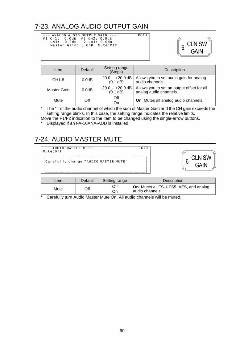
90
7-23. ANALOG AUDIO OUTPUT GAIN --- ANALOG AUDIO OUTPUT GAIN --- P643 F1 Ch1: 0.0dB F2 CH2: 0.0dB
Ch3: 0.0dB F2 CH4: 0.0dB Master Gain: 0.0dB Mute:Off
Item Default Setting range
(Steps) Description
CH1-8 0.0dB -20.0 - +20.0 dB
(0.1 dB) Allows you to set audio gain for analog audio channels.
Master Gain 0.0dB -20.0 - +20.0 dB
(0.1 dB) Allows you to set an output offset for all analog audio channels.
Mute Off Off
On On: Mutes all analog audio channels.
* The “:” of the audio channel of which the sum of Master Gain and the CH gain exceeds the setting range blinks. In this case, the setting range indicates the relative limits.
Move the F1/F2 indication to the item to be changed using the single-arrow buttons. * Displayed if an FA-10ANA-AUD is installed.
7-24. AUDIO MASTER MUTE --- AUDIO MASTER MUTE --- P650 Mute:Off __________________________________________ | | |Carefully change “AUDIO MASTER MUTE” | | | | | |__________________________________________|
Item Default Setting range Description
Mute Off Off
On On: Mutes all FS-1-FS5, AES, and analog audio channels
* Carefully turn Audio Master Mute On. All audio channels will be muted.
CLN SW
GAIN6
CLN SW
GAIN6

91
7-25. EMBEDDED AUDIO OUTPUT DELAY FS1 Name:FS 1 --- EMBEDDED AUDIO OUTPUT DELAY --- P651 CH(msec) CH(msec) CH(msec) CH(msec) F1-F4 1: 2 2: 2 3: 2 4: 2 5: 2 6: 2 7: 2 8: 2 9: 2 10: 2 11: 2 12: 2 13: 2 14: 2 15: 2 16: 2 Master Delay: 2msec
Item Default Setting range
(Steps) Description
CH1-CH16 5 5ms - 1000ms Allows you to set delay for each audio channel of the selected FS.
Master 5 5ms - 1000ms Allows you to set a delay offset for all audio channels of the selected FS.
* The “:” of the audio channel of which the sum of Master delay and the CH delay exceeds the setting range blinks. In this case, the setting range indicates the relative limits.
Move the F1/F2/F3/F4 indication to the item to be changed using the single-arrow buttons. To change the FS selection to set settings, refer to section 5-3-7. “Selecting 5-channel Frame Synchronizers.”
7-26. AES AUDIO OUTPUT DELAY AES(A) --- AES AUDIO OUTPUT DELAY --- P652 F1 Ch1: 5msec F2 CH2: 5msec
Ch3: 5msec F2 CH4: 5msec Ch5: 5msec F2 CH6: 5msec Ch7: 5msec F2 CH8: 5msec Master Delay: 5msec
Item Default Setting range
(Steps) Description
CH1 - CH8 5 5ms - 1000ms Allows you to set delay for each AES audio channel in the selected slot.
Master 5 5ms - 1000ms Allows you to set a delay offset for all AES audio channels in the selected slot.
* The “:” of the audio channel of which the sum of Master Delay and the CH delay exceeds the setting range blinks. In this case, the setting range indicates the relative limits.
Move the F1/F2 indication to the item to be changed using the single-arrow buttons. To change the slot selection to set settings, select a slot from A to D (AES(A) to AES(D)) in the same procedure described in section 5-3-7. “Selecting 5-channel Frame Synchronizers.” * Displayed if an FA-10AES-BL/ FA-10AES-UBL is installed in slot A-D.
OUTPUT
DELAY7
OUTPUT
DELAY7

92
7-27. ANALOG AUDIO OUTPUT DELAY --- ANALOG AUDIO OUTPUT DELAY --- P653 F1 Ch1: 5msec F2 CH2: 5msec Ch3: 5msec CH4: 5msec
Master Delay: 5msec
Item Default Setting range
(Steps) Description
CH1 - CH4 5 5ms - 1000ms Allows you to set delay for analog audio channels.
Master 5 5ms - 1000ms Allows you to set a delay offset for all analog audio channels.
* The “:” the of audio channel of which the sum of Master delay and the CH delay exceeds the setting range blinks. In this case, the setting range indicates the relative limits.
Move the F1/F2 indication to the item to be changed using the single-arrow buttons. * Displayed if an FA-10ANA-AUD is installed.
7-28. ANALOG AUDIO INPUT/OUTPUT --- ANALOG AUDIO INPUT/OUTPUT --- P681 Input Level Output Level F1 CH1: +4dBu F2 CH1: +4dBu CH2: +4dBu CH2: +4dBu CH3: +4dBu CH3: +4dBu CH4: +4dBu CH4: +4dBu Terminal:600 Ohm
Item Default Setting range
(Steps) Description
Input Level CH1 - CH4
+4dBu
-10dBu 0dBu
+4dBu +8dBu
Allows you to set the input signal level for each analog audio channel.
Output Level CH1 - CH4
+4dBu
-10dBu 0dBu
+4dBu +8dBu
Allows you to set the output signal level for each analog audio channel.
Terminal 600 Ohm 600 Ohm
High Impedance Allows you to set termination for all analog input channels.
Move the F1/F2 indication to the item to be changed using the single-arrow buttons. * Displayed if an FA-10ANA-AUD is installed.
ANC
ANALOG9
OUTPUT
DELAY7

93
7-29. MICROPHONE SETTINGS --- MICROPHONE SETTINGS --- P682 F1 CH1/2 Input Mode:Line Level F2 Microphone Power:Off ------------------------------------------ |Caution!! | |Verify analog audio input signal(CH1/2) | |before changing settings | |__________________________________________|
Analog audio CH1 and CH2 can be used for microphone audio inputs. They can also be used for power outputs to microphones.
Item Default Setting range
(Steps) Description
CH1/2 Input Mode * Line Level Line Level
Microphone Level Allows you to set the input signal level for analog audio input CH1, and CH2.
Microphone Power *
Off Off
On(+48V)
On(+48V): Outputs power for microphones.
Selectable if Ch1/2 Input Mode is set to Microphone Level.
If Ch1/2 Input Mode is set to Line while On(+48V) is selected, the Microphone Power setting automatically turns Off.
Displayed if an FA-10ANA-AUD is installed. * This setting requires you to confirm the setting change as the setting change confirmation
regardless of the setting under the OPERATION SETTINGS menu (see sec. 6-22).
Caution
Ensure proper audio signal level input to analog audio input Ch1 and Ch2, before changing the CH1/2 Input Mode or Microphone Power setting. Incorrect level audio signal input levels may impair or damage connected devices.
ANC
ANALOG9

94
7-30. AUDIO SYSTEM --- AUDIO SYSTEM --- P686 F1 Reference Level:-20dBFS
Grade:Professional Resolution:24bit Silence Time: 2sec Silence Level(Digital):-72dbFS Silence Level(Analog) :-60dbFS
* Digital audio settings are effective on all digital signals in FSs and AES options.
Parameter Default Setting range Description
Reference Level
-20 dBFS -18 dBFS -20 dBFS
Allows you to select digital audio signal reference levels.
Grade Professional Professional
Consumer
Allows you to select an audio application for digital audio channels. Professional: Optimized for professional use Consumer: Optimized for consumer use.
Resolution 24 bit 16 bit 20 bit 24 bit
Allows you to select an audio word length for Digital Audio output signals.
Silence Time 2 sec 1 – 10 sec Allows you to set the duration to determine whether the digital/analog audio signal is silent.
Silence Level (Digital)
-72 dBFS
-72 dBFS -66 dBFS -60 dBFS -54 dBFS -48 dBFS
Allows you to select the audio level to determine whether the digital audio signal is silent.
Silence Level (Analog) *1
-60 dBFS
-72 dBFS -66 dBFS -60 dBFS -54 dBFS -48 dBFS
Allows you to select the audio level to determine whether the analog audio signal is silent.
Move the F1 indication to the item to be changed using the single-arrow buttons. *1 Displayed if the FA-10ANA-AUD is installed. Otherwise displays “Not installed.”
7-31. EMBEDDED AUDIO TEST SIGNAL --- EMBEDDED AUDIO TEST SIGNAL --- P687 F1 FS1:Off
FS2:Off FS3:Off FS4:Off FS5:Off
Parameter Default Setting range Description
FS1 - FS5 Off
OFF
500Hz Tone
1kHz Tone
Allows you to set the audio test signal output for each FS.
Move the F1 indication to the item to be changed using the single-arrow buttons.
10 SYSTEM
10 SYSTEM

95
7-32. AES AUDIO TEST SIGNAL --- AES AUDIO TEST SIGNAL --- P688 F1 Slot A:Off F2 Slot B:Off F3 Slot C:Off F4 Slot D:Off
Parameter Default Setting range Description
Slot A - D Off
OFF
500Hz Tone
1kHz Tone
Allows you to set the audio test signal output for AES audio channels for each slot.
Displays “Not installed” if no AES option is installed in the slot.
Move the F1 indication to the item to be changed using the single-arrow buttons. * Displayed if an FA-10AES-BL/ FA-10AES-UBL is installed in slot A-D.
7-33. ANALOG AUDIO TEST SIGNAL --- ANALOG AUDIO TEST SIGNAL --- P689 F1 Test Signal:Off
Parameter Default Setting range Description
Test Signal Off
OFF
500Hz Tone
1kHz Tone
Allows you to set the audio test signal output for analog audio channels.
* Displayed if an FA-10ANA-AUD is installed.
7-34. ALL AUDIO TEST SIGNAL --- ALL AUDIO TEST SIGNAL --- P690 F1 Test Signal:Off __________________________________________ | | |Carefully change “ALL AUDIO TEST SIGNAL” | | | | | |__________________________________________|
Parameter Default Setting range Description
Test Signal Off
OFF
500Hz Tone
1kHz Tone
Allows you to set the audio test signal output for all audio channels.
10 SYSTEM
10 SYSTEM
10 SYSTEM

96
7-35. EMBEDDED AUDIO INPUT STATUS FS1 Name:FS 1 --- EMBEDDED AUDIO INPUT STATUS --- P701 CH CH CH CH 1: Loss 2:Loss 3:Loss 4:Loss 5: Loss 6:Loss 7:Loss 8:Loss 9: Loss 10:Loss 11:Loss 12:Loss 13:Loss 14:Loss 15:Loss 16:Loss S:Silence NP:Non-PCM A:Async
Parameter Default Setting range Description
CH1 - CH16 - - Displays the status of embedded audio input signals for each FS.
To change the FS selection to set settings, refer to section 5-3-7. “Selecting 5-channel Frame Synchronizers.”
7-36. AES AUDIO INPUT STATUS AES(A) --- AES AUDIO INPUT STATUS --- P702 CH1:Loss CH2:Loss CH3:Loss CH4:Loss CH5:Loss CH6:Loss CH7:Loss CH8:Loss
Parameter Default Setting range Description
CH1 - CH8 - - Displays the status of AES audio input signals in slot A-D.
To change the slot selection to set settings, select a slot from A to D (AES(A) to AES(D)) in the same procedure described in section 5-3-7. “Selecting 5-channel Frame Synchronizers.” * Displayed if an FA-10AES-BL/ FA-10AES-UBL is installed in slot A-D.
7-37. ANALOG AUDIO INPUT STATUS --- ANALOG AUDIO INPUT STATUS --- P703 CH1:Loss CH2:Loss CH3:Loss CH4:Loss
Parameter Default Setting range Description
CH1 - CH4 - - Displays the status of analog audio input signals.
* Displayed if an FA-10ANA-AUD is installed.
STATUS0
STATUS0
STATUS0

97
7-38. EMBEDDED AUDIO OUTPUT STATUS FS1 Name:FS 1 --- EMBEDDED AUDIO OUT STATUS --- P704 CH CH CH CH 1: S 2:S 3:S 4:S 5: S 6:S 7:S 8:S 9: S 10:S 11:S 12:S 13:S 14:S 15:S 16:S S:Silence NP:Non-PCM
Parameter Default Setting range Description
CH1 - CH16 - - Displays the status of embedded audio output signals for each FS.
To change the FS selection to set settings, refer to section 5-3-7. “Selecting 5-channel Frame Synchronizers.”
7-39. AES AUDIO OUTPUT STATUS AES(A) --- AES AUDIO OUTPUT STATUS --- P705 CH1:Loss CH2:Loss CH3:Loss CH4:Loss CH5:Loss CH6:Loss CH7:Loss CH8:Loss
Parameter Default Setting range Description
CH1 - CH8 - - Displays the status of AES audio output signals in slot A-D.
To change the slot selection to set settings, select a slot from A to D (AES(A) to AES(D)) in the same procedure described in section 5-3-7. “Selecting 5-channel Frame Synchronizers.” * Displayed if an FA-10AES-BL/ FA-10AES-UBL is installed in slot A-D.
7-40. ANALOG AUDIO OUTPUT STATUS --- ANALOG AUDIO OUTPUT STATUS --- P706 CH1:Loss CH2:Loss CH3:Loss CH4:Loss
Parameter Default Setting range Description
CH1 - CH4 - - Displays the status of analog audio output signals.
* Displayed if an FA-10ANA-AUD is installed.
STATUS0
STATUS0
STATUS0

98
8. Event Memory
The FA-10RU can store and recall 100 event memories. It can also control 100 event memories in the connected FA-505. * FA-1010 and FA-505 settings are stored in different memory banks. Therefore, FA-1010
settings cannot be loaded to FA-505 units.
8-1. LOAD EVENT MEMORY --- LOAD EVENT MEMORY --- P811 F1 Load Mode:All Data F2 Unit:FA-10RU F3 No: 0 Name:Default Press F4 UNITY to start loading
Parameter Default Setting range Description
Load Mode All Data
All Data
FS1-FS5 Only
(*)
Allows you to select the event loading mode. All Data: Loads all setting data saved in the event. FS1-FS5 Only: Loads only the selected FS event data. (*) will be the FS name set on the FA-505.
Unit FA-10RU FA-10RU
FA-505 Allows you to select a unit from which to load the event data.
No 0 0 - 100
Allows you to select an event number to be recalled. 0: Allows you to recall the default settings.
Name displays the event name set for each event number.
F4 UNITY - -
The F4 UNITY button allows you to load the event data specified under Load Mode, Unit, or No. Displays the “Loading event memory” message while processing.
* See section 10-5. “Event Naming” for details on event name settings on the FA-10RU. Events saved on the FA-505 can be named using FA-50GUI.
In event data, adjustable ranges for White Level and Black Level vary depending on FA-505 Software Version, less than 1.21 or more than 2.00. Therefore White Level and Black Level settings will be reset if loading events that were saved in Software Version 1.21 or earlier, to an FA-505 with Software Version 2.00 or later.
EVENT
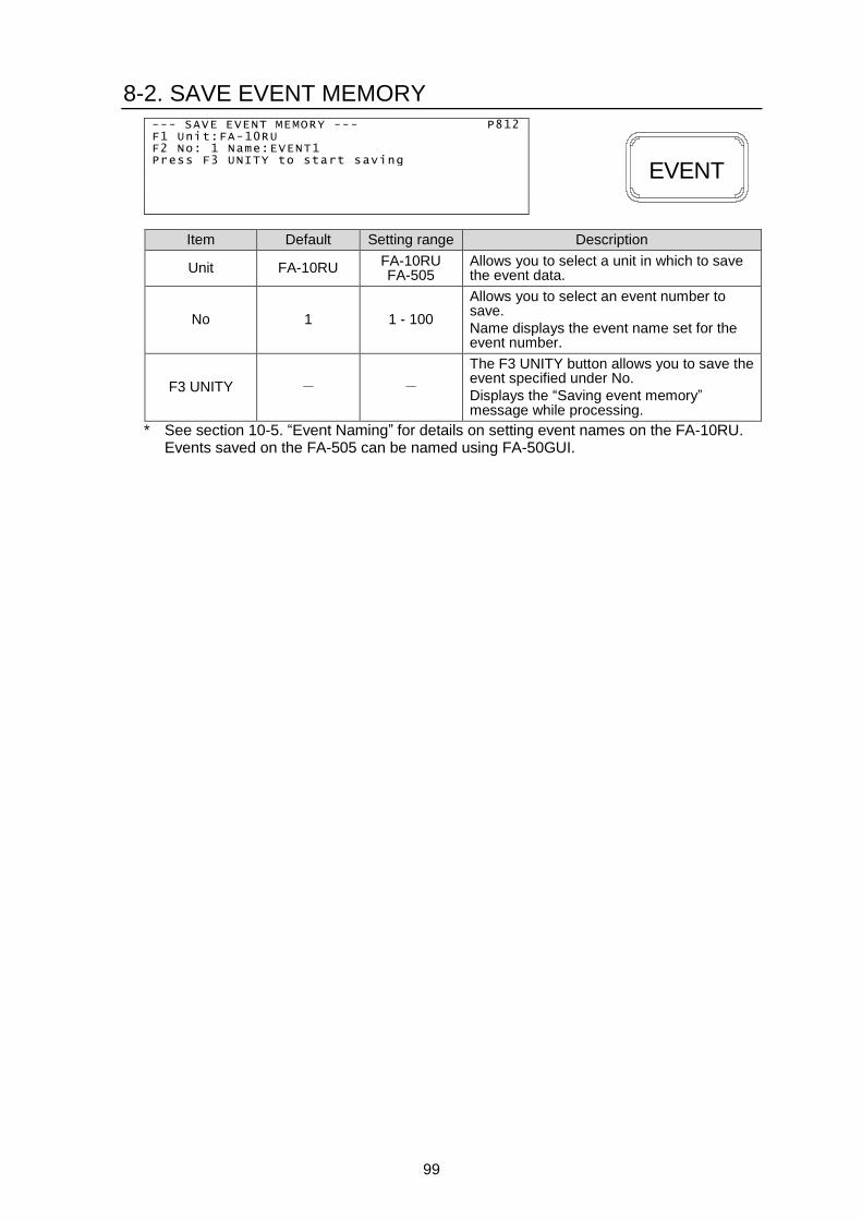
99
8-2. SAVE EVENT MEMORY --- SAVE EVENT MEMORY --- P812 F1 Unit:FA-10RU F2 No: 1 Name:EVENT1 Press F3 UNITY to start saving
Item Default Setting range Description
Unit FA-10RU FA-10RU FA-505
Allows you to select a unit in which to save the event data.
No 1 1 - 100
Allows you to select an event number to save.
Name displays the event name set for the event number.
F3 UNITY - -
The F3 UNITY button allows you to save the event specified under No.
Displays the “Saving event memory” message while processing.
* See section 10-5. “Event Naming” for details on setting event names on the FA-10RU. Events saved on the FA-505 can be named using FA-50GUI.
EVENT

100
8-3. Event Memory Load Settings List
VIDEO Settings
Menu button VIDEO related menus (Lit green) Event Loading
Load All Load FS1-5 Only
1 PROC
EMB
VIDEO PROCESS AMPLIFIER VIDEO LEVEL Y LEVEL CHROMA LEVEL SETUP/BLACK LEVEL HUE
Yes Yes
2 CC
SETUP
COLOR CORRECTION COLOR CORRECTION WHITE LEVEL COLOR CORRECTION BLACK LEVEL COLOR CORRECTION GAMMA LEVEL COLOR SPACE DYNAMIC RANGE CONTROL
Yes Yes
3 CLIP
DWN MIX VIDEO CLIP Yes Yes
4 BY-PASS
MAPPING SDI VIDEO BY-PASS COLOR CORRECTION BYPASS
No No
5 INPUT
AES FS VIDEO IN SETTINGS FS SYNC FORMAT SETTINGS
Yes Yes
6 CLN SW
GAIN
CLEAN SWITCH SETTINGS Yes No
SALVO LOAD SALVO SAVE OPERATION SETTINGS
No No
7 OUTPUT
DELAY SDI VIDEO OUTPUT PORT ASSIGN Yes No
UP/DOWN CONVERTER MODE UP/DOWN CONVERTER SIZE/POS UP/DOWN CONVERTER CROPPING IMPROVEMENT IN CONVERTER UP/DOWN CONVERTER SIDE COLOR
Yes Yes
8 OPTION
SLOT A GPI FUNCTION SETTINGS *1 SLOT B GPI FUNCTION SETTINGS *1 SLOT C GPI FUNCTION SETTINGS *1 SLOT D GPI FUNCTION SETTINGS *1
No No
9 ANC
ANALOG
SDI MULTIPLEXER EMBEDDED AUDIO MULTIPLEXER ANCILLARY DETECT LINE
Yes Yes
INPUT ANCILLARY STATUS1 INPUT ANCILLARY STATUS2
No No
EMBEDDED ANCILLARY 1 EMBEDDED ANCILLARY 2 EMBEDDED ANCILLARY 3
Yes Yes
EMBEDDED TIME CODE Yes Yes *1
TIME CODE GENERATOR Yes No
10 SYSTEM
VIDEO INPUT LOSS FS MODE SETTINGS VIDEO SYSTEM PHASE/POSITION
Yes Yes
VIDEO FREEZE Yes Yes
SD LINE MASK 3G SDI OUTPUT LEVEL VIDEO TEST SIGNAL VIDEO SYSTEM FRAME RATE
Yes Yes
0 STATUS
VIDEO INPUT STATUS SDI VIDEO OUTPUT STATUS PAYLOAD ID INPUT STATUS MAIN UNIT ALARM INFORMATION MAIN UNIT VERSION INFORMATION OPTION VERSION INFORMATION OTHER OPTION INFORMATION
No No
*1 LTC Port settings are unloaded.

101
AUDIO Settings
Menu button AUDIO related settings (Lit orange) Event Loading
Load All Load FS1-5 Only
1 PROC
EMB
EMBEDDED AUDIO DEMULTIPLEX
EMBEDDED AUDIO ERROR SENSE
FADE IN/OUT
EMBEDDED AUDIO MULTIPLEX
Yes No
2 CC
SETUP
EMBEDDED AUDIO SRC MODE
AES AUDIO SRC MODE
EMBEDDED AUDIO IN POLARITY
AES AUDIO IN POLARITY
SDI EMBEDDED AUDIO MONO SUM
AES AUDIO MONO SUM
ANALOG AUDIO MONO SUM
Yes No
3 CLIP
DWN MIX
AUDIO DOWN MIX MODE
AUDIO DOWN MIX ASSIGN Yes No
4 BY-PASS
MAPPING
EMBEDDED AUDIO GROUP1/2 MAPPING
EMBEDDED AUDIO GROUP3/4 MAPPING
AES AUDIO OUTPUT MAPPING
ANALOG AUDIO OUTPUT MAPPING
Yes No
5 INPUT
AES
AES AUDIO HYSTERESIS Yes No
FA-10AES-UBL TERMINAL IN/OUT No No
6 CLN SW
GAIN
EMBEDDED AUDIO OUTPUT GAIN
AES AUDIO OUTPUT GAIN
ANALOG AUDIO OUTPUT GAIN
Yes No
AUDIO MATER MUTE No No
7 OUTPUT
DELAY
EMBEDDED AUDIO OUTPUT DELAY
AES AUDIO OUTPUT DELAY
ANALOG AUDIO OUTPUT DELAY
Yes No
9 ANC
ANALOG
ANALOG AUIO INPUT/OUTPUT Yes No
MICROPHONE SETTINGS No No
10 SYSTEM
AUDIO SYSTEM
EMBEDDED AUDIO TEST SIGNAL
AES AUDIO TEST SIGNAL
ANALOG AUDIO TEST SIGNAL
ALL AUDIO TEST SIGNAL
Yes No
0 STATUS
EMBEDDED AUDIO INPUT STATUS
AES AUDIO INPUT STATUS
ANALOG AUDIO INPUT STATUS
EMBEDDED AUDIO OUTPUT STATUS
AES AUDIO OUTPUT STATUS
ANALOG AUDIO OUTPUT STATUS
No No

102
9. FA-10RU SYSTEM Settings and Viewing
9-1. FA-10RU SYSTEM Menus
Pressing the MU SELECT button, then the 10 SYSTEM button (lit red), opens the menu as shown below, allowing you to verify the FA-10RU GPI function assignments, front panel display settings, and software versions.
9-1-1. LOAD GPI INPUT PATTERN
Allows you to assign functions to GPI 10 inputs / outputs simultaneously using patterns. See Sec. 11-3. "GPI1-GPI3 Pin Assignments" for details on pin arrangements. See Sec. 11-2. "GPI Input Patterns" for details on function patterns. See Sec. 9-1-2-1. "Setting Details via Setting 1-4" for details on individual input settings. --- LOAD GPI INPUT PATTERN --- P821 F1 GPI1 BLOCK:None F2 GPI2 BLOCK:None F3 GPI3 BLOCK:None Press F4 UNITY to start pattern loading
Item Default Setting range Description
GPI1 BLOCK
---
--- None
MU Select FS Select
Process(FS1-FS10) *1 Video Level(FS1-FS10) *1
Chroma Level(FS1-FS10) *1 Setup/Black(FS1-FS10) *1
Hue(FS1-FS10) *1 CC (FS1-FS10) *1
CC White(FS1-FS10) *1 CC Black(FS1-FS10) *1
CC Gamma(FS1-FS10) *1 BY-PASS(SDI1-SDI10) *2 Clean SW (Destination)
Clean SW (Source) Clean SW (Mode/Take)
Clean SW (Salvo1-10 Load) Clean SW (Salvo1-10 Save)
Clean SW (Salvo1-5 Load/Save)
Time Code Generator Freeze(FS1-FS10) *1
Audio Gain(FS1-FS10) *1 Audio Delay(FS1-FS10) *1
Event(No1-10 Load) Event(No1-10 Save)
Event(No1-5 Load/Save) Menu1 Select Menu2 Select Menu3 Select Menu4 Select
Status1 Status2
Allows you to assign functions to GPI Input/Output 1-10 simultaneously.
(See Sec. 11-2. "GPI Input Patterns")
GPI2 BLOCK
--- Ditto Allows you to assign functions to GPI Input/Output 11-20 simultaneously.
(See Sec. 11-2. "GPI Input Patterns")
GPI3 BLOCK
--- Ditto Allows you to assign functions to GPI Input/Output 21-30 simultaneously.
(See Sec. 11-2. "GPI Input Patterns")
*1 Do not select FS6 to FS10 when connecting to FA-505 units.
*2 Do not select BY-PASS(SDI6) to BY-PASS(SDI10) when connecting to FA-505 units.
LOCKMU SEL
10 SYSTEM

103
9-1-2. GPI INPUT PORT FUNCTION
Allows you to assign functions to GPI input pins. --- GPI INPUT PORT FUNCTION --- P822 F1 Port:GPI1 PORT 1(FA-AUX30 Left Block)
Setting1:None Setting2:None Setting3:None Setting4:None
Select an item to set using single-arrow buttons. F1, F2, F3, or F4 next to the selected item blinks.
Item Default Setting range Description
Port GPI1 Port 1
(FA-AUX30 Left Block)
GPI1 Port 1-10 (FA-AUX30 Left Block)
GPI2 Port11-20 (FA-AUX30 Center Block)
GPI3 Port21-30 (FA-AUX30 Right Block)
Allows you to select a GPI input pin to assign functions to.
Assigned settings are displayed under Settings 1-4.
Setting1
to Setting4
None See section 9-1-2-1. “Setting Details via
Setting1-4.”
Allows you to specify a function to be assigned to the GPI input pin selected under Port using Setting 1-4.
9-1-2-1. Setting Details via Setting 1-4
Settings list under Settings 1-4 No Setting1 Setting2 Setting3 Setting4
1 None --- --- ---
2 MU Select Menu
Disconnected ID1-ID100
None FS1-FS10
---
3 FS Select FS1-FS10 --- ---
4 Video Process
Video Process Amplifier Video Level
Chroma Level Setup/Black level
Hue
Menu FS1-FS10
---
5 Color Corrector
Color Correction White Level Black Level
Gamma Level
Menu FS1-FS10
---
6 Freeze (Mode)
Menu Frame Odd Even
None FS1-FS10
None Menu
7 Freeze (On/Off) On Off
On/Off
None All
FS1-FS10
None Menu
8 By-pass
Menu On Off
On/Off
All FS1-FS10
None Menu
9 Audio Gain(Embedded) Menu
FS1-FS10 --- ---
10 Audio Gain(AES) Menu
Option Slot A-D --- ---
11 Audio Gain(Analog) --- --- ---
12 Audio Delay(Embedded) Menu
FS1-FS10 --- ---
13 Audio Delay(AES) Menu
Option Slot A-D --- ---
14 Audio Delay(Analog) --- --- ---
15 Time Code Menu, Start, Stop, Reset, Preset None, Menu
None FS1 LTC FS1 VITC
FS1 LTC & VITC FS2 LTC FS2 VITC
FS2 LTC & VITC
LOCKMU SEL
10 SYSTEM

104
16 Clean Switch
Mode Direct Mode Take Mode
Take --- Destination Destination1-10
Source Source1(FS1)-10(FS10)
17 Video Test Signal
Menu --- ---
Video Test Signal(Off)
All FS1-FS10
Video Test Signal(100% CB) On
On/Off On (with Menu Move)
On/Off (with Menu Move)
Video Test Signal(75% CB)
Video Test Signal(SMPTE CB)
Video Test Signal(RAMP)
18 Audio Test
Signal(Embedded)
Menu --- ---
Audio Test Signal(Off)
FS1-FS10 Audio Test Signal(500Hz) On
On/Off On (with Menu Move)
On/Off (with Menu Move) Audio Test Signal(1kHz)
19 Audio Test Signal(AES)
Menu --- ---
Audio Test Signal(Off)
Option Slot A-D Audio Test Signal(500Hz) On
On/Off On (with Menu Move)
On/Off (with Menu Move) Audio Test Signal(1kHz)
20 Audio Test Signal(Analog)
Menu ---
None Menu
Audio Test Signal(Off) ---
Audio Test Signal(500Hz) On On/Off Audio Test Signal(1kHz)
21 All Audio Test
Menu ---
---
Audio Test Signal(Off) None Menu
Audio Test Signal(500Hz) On On/Off Audio Test Signal(1kHz)
22 GPI Lock On, Off, On/Off --- ---
23 Memory Load Event, Salvo Menu, Default, No1-100 FA-10RU, MU
24 Memory Save Event, Salvo Menu, No1-100 FA-10RU, MU
25 Menu Move P000-P1499 None, FS1-FS10 None, Line1-Line8
26 Color Corrector Split Off, Mode1-3 None, FS1-FS10 None, Menu
27 DRC Operate *4 On, Off, On/Off None, FS1-FS2 None, Menu
28 Input Color Space Rec. ITUR BT.709
Rec. ITUR BT.2020 User1-5
None, FS1-FS5 None, Menu
29 Output Color Space Rec. ITUR BT.709
Rec. ITUR BT.2020 User1-5
None, FS1-FS5 None, Menu
30 Input Gumma (EOTF) Bypass,Pattern1-13 None, FS1-FS5 None, Menu
31 Output Gumma(OETF) Bypass,Pattern1-13 None, FS1-FS5 None, Menu
The above table is the GPI input pin function setting list. An “---“ indicates no setting.
*1 Do not select FS6 to FS10 when connecting to FA-505 units.
*2 Do not select BY-PASS(SDI6) to BY-PASS(SDI10) when connecting to FA-505 units.
*3 Do not select Destination6 to 10 when connecting to FA-505 units.
*4 Do not select this when connecting to FA-505 units.
None
No. Setting1 Setting2 Setting3 Setting4
1 None --- --- ---
Specifies the GPI input pin function setting. If Setting1 is set to None, no function is set to the pin. Nothing occurs even if the pin circuit is closed.
MU Select No. Setting1 Setting2 Setting3 Setting4
2 MU Select Menu
Disconnect ID1 - ID100
None FS1 - FS10
---
Selecting MU Select under Setting 1, and an ID from among ID1 – ID100 under Setting 2 allows you to establish a connection to the FA-505 of the selected ID, when the circuit is closed. If Menu is selected under Setting 2, the MU Select page opens instead of establishing a new connection.

105
If Disconnect is selected under Setting 2, the FA-10RU is disconnected from the main unit. See section 5-2-1. “Connecting in Unit ID Selection Mode” for details on IDs. To change an FS along with the connection, select an FS under Setting 3.
FS Select No. Setting1 Setting2 Setting3 Setting4
3 FS Select FS1 - FS10 --- ---
Selecting FS Select under Setting 1, and an FS under Setting 2, allows you to switch to the selected FS, when the circuit is closed. See section 5-3-7. “Selecting 5-channel Frame Synchronizers” for details on FS switching. Do not select FS6 to FS10 when connecting to FA-505 units.
Video Process No. Setting1 Setting2 Setting3 Setting4
4 Video Process
Video Process Amplifier Video Level
Chroma Level Setup/Black level
Hue
Menu FS1 - FS10
---
Selecting Video Process under Setting 1, and a menu under Setting 2, allows you to open the selected menu, when the circuit is closed. To change an FS at the same time, select an FS under Setting 3. If Setting 3 is set to Menu, FS will remain unchanged, and only the menu display will change. See section 6-1. “VIDEO PROCESS AMPLIFIER”, 6-2. “VIDEO LEVEL”, 6-4. “CHROMA LEVEL”, 6-5. “SETUP/BLACK LEVEL”, and 6-6. “HUE.” Do not select FS6 to FS10 when connecting to FA-505 units.
Color Corrector No. Setting1 Setting2 Setting3 Setting4
5 Color Corrector
Color Correction White Level Black Level
Gamma Level
Menu FS1 - FS10
---
Selecting Color Corrector under Setting 1, and a menu selection under Setting 2 allows you to display the selected menu. To switch an FS at the same time, select an FS under Setting 3. If Setting 3 is set to Menu, FS will remain unchanged, and only the menu display will be changed. See section 6-7. “COLOR CORRECTION”, 6-8. “COLOR CORRECTION WHITE LEVEL”, 6-9. “COLOR CORRECTION BLACK LEVEL”, and 6-10. “COLOR CORRECTION GAMMA LEVEL” for details. Do not select FS6 to FS10 when connecting to FA-505 units.
Freeze No. Setting1 Setting2 Setting3 Setting4
6 Freeze (Mode)
Menu Frame Odd Even
None FS1-FS10
None Menu
7 Freeze (On/Off) On Off
On/Off
None All
FS1 - FS10
None Menu
Selecting Freeze under Setting 1, and a Freeze mode under Setting 2, allows you to change Freeze mode among Frame, Odd, and Even, when the circuit is closed. Freeze On/Off settings turns the Freeze function On or Off. On/Off alternately turns On and Off, when the circuit is closed. Select an FS for which to set Freeze under Setting 3. To set Freeze for all FSs 1 to 5, select All. To change the menu display when the circuit is closed, select Menu under Setting 4. To change only the menu display, select None under Setting 3 and Menu under Setting 4. See section 6-50. “VIDEO FREEZE” for details. Do not select FS6 to FS10 when connecting to FA-505 units.

106
By-Pass No. Setting1 Setting2 Setting3 Setting4
8 By-pass
Menu On Off
On/Off
--- All
SDI1 - SDI10
None Menu
Selecting Bypass under Setting 1 allows you to turn On or Off the Bypass function by selecting On/Off under Setting 2. On/Off alternately turns Bypass On and Off, when the circuit is closed. Select an SDI connector to be bypassed under Setting 3. To bypass all SDI connectors, set to All. To change the menu display when the circuit is closed, select Menu under Setting 4. See section 6-15. “SDI VIDEO BY-PASS” for details. Do not select FS6 to FS10 when connecting to FA-505 units.
Audio Gain (Embedded) No. Setting1 Setting2 Setting3 Setting4
9 Audio Gain(Embedded) Menu
FS1 - FS10 --- ---
Selecting Audio Gain(Embedded) under Setting 1 opens the Audio Gain (Embedded) menu when the circuit is closed. To change an FS at the same time, select an FS under Setting 2. See section 7-21. “EMBEDDED AUDIO OUTPUT GAIN” for details. Do not select FS6 to FS10 when connecting to FA-505 units.
Audio Gain(AES) No. Setting1 Setting2 Setting3 Setting4
10 Audio Gain(AES) Menu
Option Slot A - D --- ---
Selecting Audio Gain(AES) under Setting 1 opens the Audio Gain(AES) menu when the circuit is closed. To switch Options, select an Option under Setting 2. Ineffective if no AES Option is installed. See section 7-22. “AES AUDIO OUTPUT GAIN” for details.
Audio Gain(Analog) No. Setting1 Setting2 Setting3 Setting4
11 Audio Gain(Analog) --- --- ---
Selecting Audio Gain(Analog) under Setting 1 opens the Audio Gain(Analog) menu when the circuit is closed. Ineffective if no Analog Option is installed. See section 7-23. “ANALOG AUDIO OUTPUT GAIN” for details.
Audio Delay(Embedded) No. Setting1 Setting2 Setting3 Setting4
12 Audio Delay(Embedded) Menu
FS1 - FS10 --- ---
Selecting Audio Delay(Embedded) under Setting 1 opens the Audio Delay(Embedded) menu, when the circuit is closed. To change FS at the same time, select an FS under Setting 2. See section 7-25. “EMBEDDED AUDIO OUTPUT DELAY” for details. Do not select FS6 to FS10 when connecting to FA-505 units.
Audio Delay(AES) No. Setting1 Setting2 Setting3 Setting4
13 Audio Delay(AES) Menu
Option Slot A - D --- ---
Selecting Audio Delay(AES) under Setting 1 opens the Audio Delay(AES) menu, when the circuit is closed. To switch Options, select an Option under Setting 2. Effective if an AES Option is installed. See section 7-26. “AES AUDIO OUTPUT DELAY” for details.
Audio Delay(Analog) No. Setting1 Setting2 Setting3 Setting4
14 Audio Delay(Analog) --- --- ---
Selecting Audio Delay(Analog) under Setting 1 opens the Audio Delay(Analog) menu, when the circuit is closed. Effective if an Analog Option is installed. See section 7-27. “ANALOG AUDIO OUTPUT DELAY” for details

107
Time Code No. Setting1 Setting2 Setting3 Setting4
15 Time Code
Menu Start Stop Reset Preset
--- None Menu
None FS1 LTC FS1 VITC
FS1 LTC & VITC FS2 LTC FS2 VITC
FS2 LTC & VITC
Selecting Time Code under Setting 1 allows you to control Time code generation by selecting the operation under Setting 2. To display the Time Code menu, select Menu under Setting 3. See section 6-31. “TIMECODE GENERATOR” for details. Setting1, 2 and 3 are effective and Setting4 is ineffective for FA-505 units.
Clean Switch No. Setting1 Setting2 Setting3 Setting4
16 Clean Switch
Mode Direct Mode Take Mode
Take ---
Destination Destination1 - 10 ---
Source Source1 (FS1) - 10 (FS10) ---
Selecting Clean Switch under Setting 1 allows you to control Clean Switching by selecting the operation under Setting 2 and 3. See section 6-19 “CLEAN SWITCH SETTINGS” for details.
Video Test Signal No. Setting1 Setting2 Setting3 Setting4
17 Video Test Signal
Menu --- ---
Video Test Signal(Off)
All FS1 - FS10
None Menu
Video Test Signal(100% CB) On (with Menu Move)
On/Off (with Menu Move)
Video Test Signal(75% CB)
Video Test Signal(SMPTE CB)
Video Test Signal(RAMP)
Selecting Video Test Signal under Setting 1 allows a video test signal, selected under Setting 2, to be output when the circuit is closed. To change the menu display, select Menu under Setting 2. Setting3 allows you to select an FS to be controlled. All outputs the test signal to all FSs. See section 6-53. “VIDEO TEST SIGNAL” for details. Do not select FS6 to FS10 when connecting to FA-505 units.
Audio Test Signal(Embedded) No. Setting1 Setting2 Setting3 Setting4
18 Audio Test Signal(Embedded)
Menu --- ---
Audio Test Signal(Off)
FS1 - FS10
None Menu
Audio Test Signal(500Hz) On (with Menu Move)
On/Off (with Menu Move)
Audio Test Signal(1kHz)
Selecting Audio Test Signal(Embedded) under Setting 1 allows an audio test signal, selected under Setting 2, to be output when the circuit is closed. To change the menu display, select Menu under Setting 2. Setting3 allows you to select an FS to be controlled. See section 7-31. “EMBEDDED AUDIO TEST SIGNAL” for details. Do not select FS6 to FS10 when connecting to FA-505 units.
Audio Test Signal(AES) No. Setting1 Setting2 Setting3 Setting4
19 Audio Test Signal(AES)
Menu --- ---
Audio Test Signal(Off)
Option Slot A - D
None Menu
Audio Test Signal(500Hz) On (with Menu Move)
On/Off (with Menu Move)
Audio Test Signal(1kHz)

108
Selecting Audio Test Signal(AES) under Setting 1 allows an audio test signal, selected under Setting 2, to be output when the circuit is closed. To change the menu display, select Menu under Setting 2. Setting3 allows you to select an FS to be controlled. On/Off (with Menu Move) under Setting 4 alternates AES audio test signal output On and Off. Ineffective if no AES option is installed. See section 7-32. “AES AUDIO TEST SIGNAL” for details.
Audio Test Signal(Analog) No. Setting1 Setting2 Setting3 Setting4
20 Audio Test Signal(Analog)
Menu --- ---
Audio Test Signal(Off) --- None Menu
Audio Test Signal(500Hz) On On/Off Audio Test Signal(1kHz)
Selecting Audio Test Signal(Analog) under Setting 1 allows an audio test signal, selected under Setting 2, to be output when the circuit is closed. To change the menu display, select Menu under Setting 2. On/Off (with Menu Move) under Setting 4 alternates Analog audio test signal output On and Off. Ineffective if no Analog Option is installed. See section 7-33. “ANALOG AUDIO TEST SIGNAL” for details.
All Audio Test No. Setting1 Setting2 Setting3 Setting4
21 All Audio Test
Menu --- ---
Audio Test Signal(Off) --- None Menu
Audio Test Signal(500Hz) On On/Off
None Menu Audio Test Signal(1kHz)
Selecting All Audio Test under Setting 1 allows an audio test signal, selected under Setting 2, to be output when the circuit is closed. To change the menu display, select Menu under Setting 2. On/Off (with Menu Move) under Setting 4 alternates audio test signal output On and Off. See section 7-34. “ALL AUDIO TEST SIGNAL” for details.
GPI Lock No. Setting1 Setting2 Setting3 Setting4
22 GPI Lock On Off
On/Off --- ---
Selecting GPI Lock under Setting 1 allows you to control the GPI Lock function by selecting On, Off or On/Off under Setting 2. On/Off alternates lock and unlock when the circuit is closed.
Memory Load No. Setting1 Setting2 Setting3 Setting4
23 Memory Load Event Salvo
Menu Default
No1 - 100
FA-10RU MU
Selecting Memory Load allows you to load the memory data selected under Setting 2, 3 and 4. See section 6-20. “SALVO LOAD”, and 8-1. “LOAD EVENT MEMORY” for details. Setting 2 allows you to select a memory type. Setting 3 allows you to select a memory number. (To change the Menu display, select Menu.) Setting 4 allows you to select a unit from which to load the memory data.
Memory Save No. Setting1 Setting2 Setting3 Setting4
24 Memory Save Event Salvo
Menu No1 - 100
FA-10RU MU
Selecting Memory Save under Setting 1 allows you to save the memory data to the memory specified under Setting 2, 3 and 4, when the circuit is closed. See section 6-21. “SALVO SAVE”, and 8-2. “SAVE EVENT MEMORY” for details. Setting 2 allows you to select a memory type. Setting 3 allows you to select a memory number. (To change the Menu display, select Menu.) Setting 4 allows you to select a unit to which to save the memory data.

109
Menu Move No. Setting1 Setting2 Setting3 Setting4
25 Menu Move P000 - P1499 None
FS1 - FS10 None
Line1 - Line8
Selecting Menu Move under Setting 1 allows you to display the menu selected under Setting 2, 3, and 4 when the circuit is closed. Setting 2 allows you to select a menu number. Setting 3 allows you to change an FS. Setting 4 allows you to select the menu display row in which to set a setting. Lines are numbered 1 to 8 from top to bottom. * If a menu number that does not exist is selected under Setting 2, the menu display will not be changed. If the selected menu does not contain any FS or line selections, those settings will be ignored. If an FA-1010 menu number is specified during FA-505 operation, the remote unit automatically replaces it with the corresponding FA-505 menu. Do not select FS6 to FS10 when connecting to FA-505 units.
Color Correction Split No. Setting1 Setting2 Setting3 Setting4
26 Color Correction Split Off,Mode1, Mode2, Mode3 None
FS1 - FS10 None Menu
Selecting Color Correction Split under Setting 1 allows you to display the menu selected under Setting 2, 3, and 4 when the circuit is closed. Setting 2 allows you to specify the Color Correction Split mode. Setting 3 allows you to change an FS. Setting 4 allows you to change the menu. If an FA-1010 menu number is specified during FA-505 operation, the remote unit automatically replaces it with the corresponding FA-505 menu. Do not select FS6 to FS10 when connecting to FA-505 units.
DRC Operate No. Setting1 Setting2 Setting3 Setting4
27 DRC Operate On,Off,On/Off None
FS1-FS2 None Menu
Enabled for FA-9600 units but disabled for FA-1010/505 units.
Input Color Space No. Setting1 Setting2 Setting3 Setting4
28 Input Color Space Rec. ITUR BT.709 Rec. ITUR BT.2020
User1-5
None FS1-FS5
None Menu
Selecting Input Color Space under Setting 1 allows you to display the menu selected under Setting 2, 3, and 4 when the circuit is closed. Setting 2 allows you to specify the Input Color Space mode. Setting 3 allows you to select an FS. Setting to None selects the currently controlled FS. Setting 4 allows you to change the menu. Do not use for FA-1010 units.
Output Color Space No. Setting1 Setting2 Setting3 Setting4
29 Output Color Space Rec. ITUR BT.709 Rec. ITUR BT.2020
User1-5
None FS1-FS5
None Menu
Selecting Output Color Space under Setting 1 allows you to display the menu selected under Setting 2, 3, and 4 when the circuit is closed. Setting 2 allows you to specify the Output Color Space mode. Setting 2 allows you to specify the Input Color Space mode. Setting 3 allows you to select an FS. Setting to None selects the currently controlled FS. Setting 4 allows you to change the menu. Do not use for FA-1010 units.

110
Input Gumma (EOTF) No. Setting1 Setting2 Setting3 Setting4
30 Input Gumma (EOTF) Bypass
Pattern1-13 None
FS1-FS5 None Menu
Selecting Input Gumma (EOTF) under Setting 1 allows you to display the menu selected under Setting 2, 3, and 4 when the circuit is closed. Setting 2 allows you to specify the Input Gumma (EOTF) mode: Bypass or Pattern1-13. Setting 3 allows you to change an FS. Setting to None selects the currently controlled FS. Setting 4 allows you to change the menu. Do not use for FA-1010 units.
Output Color Space No. Setting1 Setting2 Setting3 Setting4
31 Output Gumma (OETF) Bypass
Pattern1-13 None
FS1-FS5 None Menu
Selecting Output Gumma (OETF) under Setting 1 allows you to display the menu selected under Setting 2, 3, and 4 when the circuit is closed. Setting 2 allows you to specify the Output Gumma (OETF) mode: Bypass or Pattern1-13. Setting 3 allows you to change an FS. Setting to None selects the currently controlled FS. Setting 4 allows you to change the menu. Do not use for FA-1010 units.

111
9-1-3. GPI OUTPUT PORT FUNCTION
Allows you to assign functions to GPI output pins.
--- GPI OUTPUT PORT FUNCTION --- P823 1 Port:GPI1 PORT 1(FA-AUX30 Left Block) F2 Setting :None F3 Polarity:Normal
Item Default Setting range Description
Port GPI1 Port 1
(FA-AUX30 Right Block)
GPI1 Port 1 - 10(FA-AUX30 Left Block) GPI2 Port11 - 20 (FA-AUX30 Center Block) GPI3 Port21 - 30 (FA-AUX30 Right Block)
Allows you to select a GPI output pin for which to assign functions.
Setting None
None Follow GPI In Setting
All DC/FAN Alarm FA-10RU FAN Alarm
MU/FA-10RU FAN Alarm MU FAN1-4 Alarm DC Power Alarm
DC Power 1-2Alarm Reference Input Video Status FS1-10 Input Video Status *1 FS1-10 Input Audio Status *1 Option A -D Input Audio Status
Allows you to specify a function to be assigned to the GPI output pin.
See section 9-1-3-1. “GPI OUTPUT Functions” for details on output functions.
Polarity Normal Normal
Invert
Allows you to select the output polarity.
Select Normal when connecting with the FA-AUX30.
*1 In case of FA-505, no status information is displayed for FS6 to FS10.
9-1-3-1. GPI OUTPUT Functions
Settings Description
None No output
Follow GPI In Setting Outputs a signal the same as that specified for the input.
All DC/FAN Alarm *1 Outputs a signal if an alarm is detected in an FA-1010 / FA-505 FAN, power, or FA-10RU FAN unit.
FA-10RU FAN Alarm Outputs a signal if an alarm is detected in the FA-10RU FAN unit.
MU/FA-10RU FAN Alarm *1 Outputs a signal if an alarm is detected in an FA-1010 / FA-505 or FA-10RU FAN unit.
MU FAN1 Alarm *1 Outputs a signal if an alarm is detected in FA-1010 / FA-505 FAN 1.
MU FAN2 Alarm *1 Outputs a signal if an alarm is detected in FA-1010 / FA-505 FAN 2.
MU FAN3 Alarm *1 Outputs a signal if an alarm is detected in FA-1010 / FA-505 FAN 3.
MU FAN4 Alarm *1 Outputs a signal if an alarm is detected in FA-1010 / FA-505 FAN 4.
DC Power Alarm *1 Outputs a signal if an alarm is detected in an FA-1010 / FA-505 power supply unit.
DC Power 1 Alarm *1 Outputs a signal if an alarm is detected in FA-1010 / FA-505 power supply unit 1.
DC Power 2 Alarm *1 Outputs a signal if an alarm is detected in FA-1010 / FA-505 power supply unit 2.
Reference Input Video Status *1 Outputs a signal if the reference signal input is lost.
FS1 - 10 Input Video Status *1, *2 Outputs a signal if the input video signal in FS1 - FS10 is lost.
FS1 - 10 Input Audio Status *1, *2 Outputs a signal if the embedded audio signal in FS1 - FS10 is lost.
OptionA - D Input Audio Status *1 Outputs a signal if the audio signal in Option A – OptionD is lost.
*1 No main unit connection is recognized as a normal state.
*2 In case of FA-505, no signals output for FS6 to FS10.
LOCKMU SEL
10 SYSTEM

112
9-1-4. GPI OUTPUT BRIGHTNESS
--- GPI OUTPUT BRIGHTNESS --- P824 F1 GPI BLOCK: GPI1 (FA-AUX30 Left Block) F2 Port 1: 50 F3 Port 2 : 50 Port 3: 50 Port 4 : 50 Port 5: 50 Port 6 : 50 Port 7: 50 Port 8 : 50 Port 9: 50 Port 10: 50 F4 All Port Setting
Item Default Setting range Description
GPI BLOCK
GPI1 (FA-AUX30 Left Block)
GPI1 (FA-AUX30 Left Block) GPI2 (FA-AUX30 Center Block) GPI3 (FA-AUX30 Right Block)
Allows you to select a block of GPI output pins.
The current brightness is shown for Ports 1 – 10.
Port1 - Port10
50 0 - 255
Allows you to set brightness for the GPI output LED.
0 – 255: Dark - Bright
The F4 UNITY button resets brightness for all LEDs to default.
9-1-5. FRONT PANEL SET
--- FRONT PANEL SETTINGS --- P831 F1 VFD Brightness:50.0% VFD Auto Off :Disable LED Brightness:Level4 FA-10RU Buzzer:Enable GPI Buzzer :Enable Front GPI Lock:Link
Item Default Setting range Description
VFD Brightness 50%
12.5%
25.0%
37.5%
50.0%
62.5%
75.0%
87.5%
100.0%
Allows you to set brightness for the front panel menu display (Vacuum Fluorescent Display).
12.5% – 100%: Dark - Bright
VFD Auto Off Disable
Disable
5min
10min
30 min
Allows you to set the duration after the last operation, before the VFD turns off.
Disable: Does not turn off.
LED Brightness Level4 Level 1 - 8 Allows you to set brightness for front panel LEDs.
Level 1 – 8: Dark - Bright
FA-10RU Buzzer Enable Disable
Enable
Disable: Disables the FA-10RU buzzer.
Enable: Enables the FA-10RU buzzer.
GPI Buzzer Enable Disable
Enable
Disable: Disables the GPI buzzer.
Enable: Enables the GPI buzzer.
Front GPI Lock Link Unlink
Link
Unlink: The front lock function does not disable GPI control.
Link: The front lock function also disables GPI control.
LOCKMU SEL
10 SYSTEM
LOCKMU SEL
10 SYSTEM

113
9-1-6. STATUS LED MODE SETTINGS
--- STATUS LED MODE SETTINGS --- P832 F1 GENLOCK LED :Normal FREEZE LED :Normal TEST SIGNAL LED:Normal BY-PASS LED :Normal FAN ALARM LED :Normal DC POWER LED :Normal
Item Default Setting range Description
GENLOCK LED Normal Normal Blink
Normal: Status lights will light to indicate statuses.
Blink: Status lights will blink to indicate statuses.
FREEZE LED Normal Normal Blink
Normal: Status lights will light to indicate statuses.
Blink: Status lights will blink to indicate statuses.
TEST SIGNAL LED Normal Normal Blink
Normal: Status lights will light to indicate statuses.
Blink: Status lights will blink to indicate statuses.
BY-PASS LED Normal Normal Blink
Normal: Status lights will light to indicate statuses.
Blink: Status lights will blink to indicate statuses.
FAN ALARM LED Normal Normal Blink
Normal: Status lights will light to indicate statuses.
Blink: Status lights will blink to indicate statuses.
DC POWER LED Normal Normal Blink
Normal: Status lights will light to indicate statuses.
Blink: Status lights will blink to indicate statuses.
Move the F1 indication to the item to be set using single-arrow buttons.
9-1-7. FA-10RU INFORMATION
Displays the FA-10RU version information and FA-10RU FAN unit status. --- FA-10RU INFORMATION --- P833 FPGA1 Version: 1.00 FPGA2 Version: 1.00 SOFT Version : 4.20 FAN Status :Normal
9-1-8. FA-10RU NETWORK INFORMATION
Allows you to veiw FA-10RU network settings. --- FA-10RU NETWORK INFORMATION --- P834 IP Address :192.168. 0.100 Subnet mask :255.255.255. 0 Default Gateway: 0. 0. 0. 0
See section 10-2. “Network Settings” for details on network settings and setting changes.
LOCKMU SEL
10 SYSTEM
LOCKMU SEL
10 SYSTEM
LOCKMU SEL
10 SYSTEM

114
10. Web Browser Settings
This section describes FA-10RU settings via a web browser on PC. (1) Connect to a computer. See section 3. “Connections.” (2) Open a web browser on the computer, and enter the address http://192.168.0.100/ (factory
default setting) in the address bar. (3) The Information page as shown below appears.
Click on a page link such as Network Settings, User Account Settings shown on the left side of the screen, the following “Windows Security” dialog will appear.
Enter your user name and password.
User name: fa10ru User password: foranetwork
Then click OK. After successful authentication, you will have access to all the FA-10RU pages.

115
10-1. Information
Click Information. The information page as shown below appears.
Unit Information
Item Description
Serial Number Displays the serial number of the FA-10RU.
FPGA1 Version Displays the version of the FA-10RU FPGA1.
FPGA2 Version Displays the version of the FA-10RU FPGA2.
Soft Version Displays the version of the FA-10RU Software.
Network Information
Item Description
IP Address Displays the IP address of the FA-10RU.
Subnet Mask Displays the subnet mask of the FA-10RU.
Default Gateway Displays the gateway of the FA-10RU.
MAC Address Displays the MAC address of the FA-10RU.
Connection Status
Item Description
Status Displays the status of connection with FA-505.
Unit ID
Displays the registered ID number if the connected FA-505 IP address is registered using Unit ID Assignment *1.
Displays an ”IP Address Select” message, if the connection is established via the IP ADDR SEL menu *2.
Host Address Displays the IP address of the connected FA-505.
TCP Port Number Displays the TCP port number of the connected FA-505.
Unit Name Displays the unit name of the connected FA-505.
*1 See section 10-4. “Unit ID Assignment“ for details. *2 See section 5-2-2. “Connecting in IP Address Selection Mode” for details.

116
10-2. Network Settings
Clicking Network Settings opens the dialog box as shown below.
To change the network address, change the settings and click Submit. Changes will be applied after reboot or restart (see section 10-8) is performed.
10-3. User Account Settings
Clicking User Account opens the dialog box as shown below.
To change the user account, change the settings and click Submit. The authentication dialog box will not appear if the User Name and Password setting boxes are left empty. Changes will be applied after reboot or restart (see section 10-8) is performed.

117
10-4. Unit ID Assignment
Clicking Unit ID Assignment opens the dialog box as shown below.
This page allows you to assign IP addresses to MU IDs to select units to be connected in Unit ID selection mode, described in section 5-2-1. “Connecting in Unit ID Selection Mode.” Unit Name allows you to set names for units to be displayed for settings. Once settings are complete, click Submit. (The assignments are effective without rebooting.) Unit names can be set with up to 15 alphanumeric characters.
10-5. Event Naming
Event Naming has two menu pages one for FA-1010 and the other for FA-505. Clicking Event Naming (FA-505) opens the dialog box as shown below.
Setting Procedure This page allows you to rename evens (Event1 to Event100) saved in the FA-10RU. (1) Enter a desired name (up to 15 alphanumeric characters) in the Event Name field. (2) After setting, click Submit. (3) Click “Event 21-40” to open the next page. Rename events, as necessary. (4) Event1 to Event100 (default names) can be renamed in this way. Once new names are set, these names are displayed during the event operation. See section 8. “Event Memory” for more details.

118
10-6. Salvo Naming
Salvo Naming has two menu pages one for FA-1010 and the other for FA-505. Clicking Salvo Naming (FA-505) opens the dialog box as shown below.
Setting Procedure This page allows you to rename evens (Salvo1 to Salvo100) saved in the FA-10RU. (1) Enter a desired name (up to 15 alphanumeric characters) in the Salvo Name field. (2) After setting, click Submit. (3) Click “Salvo 21-40” to open the next page. Rename events, as necessary. (4) Salvo1 to Salvo100 (default names) can be renamed in this way. Once new names are set, these names are displayed during the salvo operation. See section 6-20. “SALVO LOAD” and 6-21. “SALVO SAVE” for more details.
10-7. Backup & Restore
Clicking Backup & Restore opens the dialog box as shown below.
This dialog box allows you to save the FA-10RU settings and event data to a PC. The saved data can be recalled.

119
10-7-1. Configuration Data Backup
The FA-10RU configuration data can be saved/recalled to/from a PC as a CSV file.
Saving Configuration Data to a file on a PC (1) Click Save File: Save under “Backup Config Data Save File.” (2) Click Save in the dialog to save the data to a desired folder.
Recalling the Saved Configuration Data from a file on a PC (1) Select items in the configuration data to be recalled.
Item Description
Network Settings Recalls settings that are set in the Network Settings menu (section 10-2).
Unit ID Assignment Recalls settings that are set in the Unit ID Assignment menu (section 10-4).
Event Name Recalls settings that are set in the Event Naming menu (section 10-5).
Salvo Recalls settings that are set in the Salvo Naming menu (section 10-6).
GPI Settings Recalls GPI settings. See sections 9-1-2 to 9-1-4 for details on GPI settings.
Front Panel Settings Recalls front panel operations settings. See sections 9-1-5 and 9-1-6 for details.
(2) Click Browse under Backup Config Data to select a file in which the configuration data is
saved. * The control from the FA-10RU is disabled while saving or recalling configuration data.
It takes about 10 seconds to save configuration data and up to 10 minutes to load configuration data.
IMPORTANT
Network settings will be applied after restart.
Be sure to perform restart as described in section 10-8. “Restart.”
10-7-2. Event Data Backup
All event data for FA-505 saved in the FA-10RU can be saved/recalled to/from a file on a PC
Saving all Event Data to a file on a PC (1) Click Save File: Save under “Backup Event Data (FA-505).” (2) Click Save in the pop-up dialog to save the data to a desired folder.
Recalling the Saved Event Data from a file on a PC (1) Click Browse under “Backup Event Data (FA-505)” to select a file in which the event data
is saved. (2) Click Load, then click OK in the pop-up dialog to load the data. * The control from the FA-10RU is disabled while saving or recalling the configuration data.
It takes about 10 seconds to save or load event data.

120
10-8. Restart
Clicking Restart opens the window as shown below.
Be sure to click Restart after changing Network Settings or User Account Settings.

121
11. GPI Interface
The GPI1, GPI2 and GPI3 connectors provide a total of 30 inputs and 30 outputs. Functions can be assigned to each terminal as well as a group of terminals using patterns, which are set for specific purposes (Pattern Load). Refer to sections 9-1-1 to 9-1-3 for details on function assignments. The FA GPIO Editor also allows you to set GPI assignments on the GUI screen (see the following chapters).
11-1. FA GPIO Editor
Before performing GPI function assignments using the FA GPIO Editor, install the software into your computer from the supplied CD-ROM. GPI settings can also be backed up to and restored from files using Export and Import.
11-1-1. Software Installation
Before installing this software, close all other applications on the computer.
(1) Insert the supplied CD-ROM into the PC. Click “FA GPIO Editor > setup “ on the CD-ROM
to start the installation wizard. (2) Click Next.
(3) The Software License Agreement window appears. Read the agreement statement and
check the I accept the terms in license agreement check box, then click next. To cancel the installation, click Cancel.
NOTE
To print the Software License Agreement, click Print. Before printing the License agreement, verify that your printer is actually connected to the PC.

122
(4) The installation directory of the FA GPIO Editor is displayed. To change the default installation directory, click Change… and specify a new directory.
(5) Click Next.
(6) The last wizard page is displayed. Verify the installation settings and click Install to install
the software. To change settings, click on Back, change installation settings as required, then click Install.
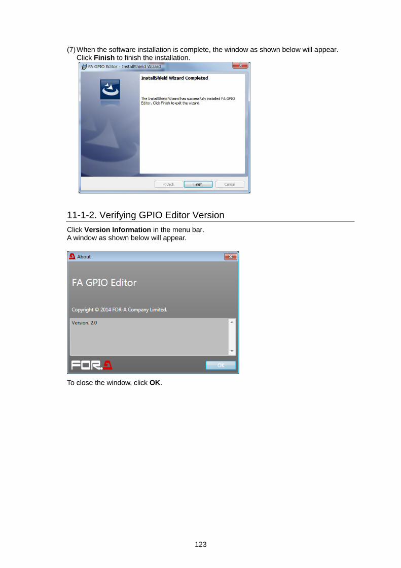
123
(7) When the software installation is complete, the window as shown below will appear.
Click Finish to finish the installation.
11-1-2. Verifying GPIO Editor Version
Click Version Information in the menu bar. A window as shown below will appear.
To close the window, click OK.

124
11-1-3. Connecting FA GPIO Editor to the FA-10RU
(1) Click the FA GPIO Editor shortcut icon on the desktop to start FA GPIO Editor.
(2) When the software window appears, enter the FA-10DCCRU IP address, user name and password. Click Load. < Default FA-10RU settings> IP address: 192.168.0.100 User name: fa10ru Password: foranetwork
(3) When the user name and password are accepted, a window as shown below is displayed
and FA-10RU GPI settings are loaded in the window.
When the user name and password are not accepted, an error pop-up dialog windows appears. Click OK to close the dialog. Enter the correct user name and password and click Load.

125
11-1-4. Setting GPI Functions
Use the FA-GPIO Editor to assign functions to 30 inputs and 30 outputs in GPI1, GPI2 and GPI3 connectors. As factory default, GPI functions are all set to None (no function).
If Using Pattern Load (input only) (1) Select a GPI connector (10 ports) by clicking a tab from the following three:
GPI Port 1 – 10 (FA-AUX30 Left Block) GPI Port 11 – 20 (FA-AUX30 Center Block) GPI Port 21 – 30 (FA-AUX30 Right Block) Note that “(FA-AUX30…)” indicates a button block (seen from the front side) when connecting an FA-AUX30 unit.
(2) Select a pattern (a combination of GPI input settings) in the Pattern Load, then click the
Load button. (See Sec.11-2. "GPI Input Patterns" for details on function patterns.) Ten GPI inputs/outputs are quickly set. Loaded settings (including output functions) can be changed. (See "If Setting Individually" below.)
(3) After all GPI settings are finished, click Apply to send the settings to the FA-10RU unit. If
a “Successful settings” message appears, GPI settings are complete.
If Setting Individually (1) Select a GPI connector (10 ports). (2) For input functions, first, set Setting 1 then set Settings 2-4 as needed.
See Sec. 9-1-2-1. "Setting Details via Setting 1-4" for details on individual input settings. See Sec. 11-3. "GPI1-GPI3 Pin Assignments" for details on pin arrangements.
(3) Set GPI output functions.
See Sec. 9-1-3-1. "GPI OUTPUT Functions" for details on output settings. To invert the polarity of GPI output pulse, change Polarity from Normal to Invert.
(4) After all GPI settings are finished, click Apply to send the settings to the FA-10RU unit. If
a “Successful settings” message appears, GPI settings are complete.
(1) Click to select a tab.
(2) Select a pattern, then click Load.
(3) Click Apply.

126
11-1-5. Exporting / Importing GPI Settings
Export to files GPI settings can be backed up to files in the computer. (1) Select File > Export in the menu bar. (2) Specify a file name and location in the pop-up windows
to save the settings. The default file name is FA-10RU GPIO.csv. Change the file name, as needed, then click OK.
Import from files GPI settings can be loaded from files in the computer. (1) Select File > Import in the menu bar. (2) Specify the file name (such as FA-10RU GPIO.csv)
and location. (3) Verify settings in the FA GPIO Editor, then click Apply
to send the settings to the FA-10RU unit.
(1) Click to select a tab.
(2) Set Setting 1 then set Settings 2-4 as needed.
(3) Set output functions
(4) Click Apply.

127
11-2. GPI Input Patterns
This section describes GPI Input setting patterns that can be selected in the LOAD GPI PATTERN menu (section 9-1-1). The following figures depict FA-AUX30 buttons. Pattern: MU Select
Item Description
MU ID1 - 10 Each button establishes a connection to the FA-505 registered with the ID 1-10. The LED lights while the unit is connected.
Pattern: FS Select
Item Description
FS1 - 10 Each button allows you to select the FS assigned to the button. The selected FS button lights.
* Do not select FS6 to FS10 when connecting to FA-505 units.

128
Pattern: Process (FS1-FS10)
Item Description
PROCESS FS1 - 10
Each button allows you to open the VIDEO PROCESS AMPLIFIER menu, and select an FS. The button LED lights if the VIDEO PROCESS AMPLIFIER menu is open and the relevant FS is selected.
* Do not select FS6 to FS10 when connecting to FA-505 units. Pattern: Video Level (FS1-FS10)
Item Description
VIDEO LEVEL FS1 - 10
Each button allows you to open the VIDEO LEVEL menu, and select an FS. The button LED lights if the VIDEO LEVEL menu is open and the relevant FS is selected.
* Do not select FS6 to FS10 when connecting to FA-505 units. Pattern: Chroma Level (FS1-FS10)
Item Description
CHROMA LEVEL FS1 -
10
Each button allows you to open the CHROMA LEVEL menu, and select an FS. The button LED lights if the CHROMA LEVEL menu is open and the relevant FS is selected.
* Do not select FS6 to FS10 when connecting to FA-505 units.

129
Pattern: Setup/Black Level (FS1-FS10)
Item Description
BLACK LEVEL FS1 - 10
Each button allows you to open the SETUP/BLACK LEVEL menu, and select an FS. The button LED lights if the SETUP/BLACK LEVEL menu is open and the relevant FS is selected.
* Do not select FS6 to FS10 when connecting to FA-505 units. Pattern: Hue (FS1-FS10)
Item Description
HUE FS1 - 10 Each button allows you to open the HUE menu, and select an FS. The button LED lights if the HUE menu is open and the relevant FS is selected.
* Do not select FS6 to FS10 when connecting to FA-505 units. Pattern: CC (FS1-FS10)
Item Description
CC FS1 - 10 Each button allows you to open the COLOR CORRECTION menu, and select an FS. The button LED lights if the COLOR CORRECTION menu is open and the relevant FS is selected.
* Do not select FS6 to FS10 when connecting to FA-505 units.

130
Pattern: CC White (FS1-FS10)
Item Description
CC WHITE FS1 - 10
Each button allows you to open the COLOR CORRECTION WHITE LEVEL menu, and select an FS. The button LED lights if the COLOR CORRECTION WHITE LEVEL menu is open and the relevant FS is selected.
* Do not select FS6 to FS10 when connecting to FA-505 units. Pattern: CC Black (FS1-FS10)
Item Description
CC BLACK FS1 - 10
Each button allows you to open the COLOR CORRECTION BLACK LEVEL menu, and select an FS. The button LED lights if the COLOR CORRECTION BLACK LEVEL menu is open and the relevant FS is selected.
* Do not select FS6 to FS10 when connecting to FA-505 units. Pattern: CC Gamma (FS1-FS10)
Item Description
CC GAMMA FS1 - 10
Each button allows you to open the COLOR CORRECTION GAMMA LEVEL menu, and select an FS. The button LED lights if the COLOR CORRECTION GAMMA LEVEL menu is open and the relevant FS is selected.
* Do not select FS6 to FS10 when connecting to FA-505 units.
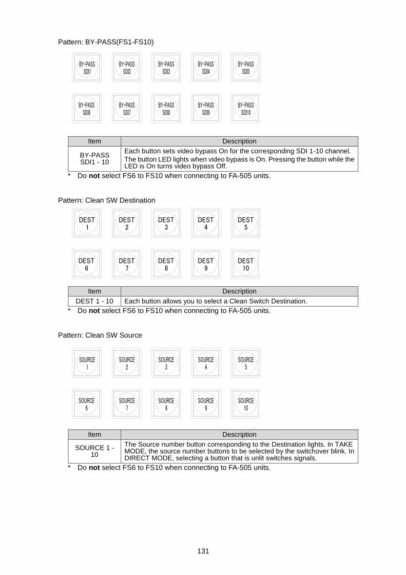
131
Pattern: BY-PASS(FS1-FS10)
Item Description
BY-PASS SDI1 - 10
Each button sets video bypass On for the corresponding SDI 1-10 channel.
The button LED lights when video bypass is On. Pressing the button while the LED is On turns video bypass Off.
* Do not select FS6 to FS10 when connecting to FA-505 units. Pattern: Clean SW Destination
Item Description
DEST 1 - 10 Each button allows you to select a Clean Switch Destination.
* Do not select FS6 to FS10 when connecting to FA-505 units. Pattern: Clean SW Source
Item Description
SOURCE 1 - 10
The Source number button corresponding to the Destination lights. In TAKE MODE, the source number buttons to be selected by the switchover blink. In DIRECT MODE, selecting a button that is unlit switches signals.
* Do not select FS6 to FS10 when connecting to FA-505 units.

132
Pattern: Clean SW(Mode/Take)
Item Description
DIRECT MODE The selected DIRECT MODE or TAKE MODE button lights.
If a Source selection is changed in TAKE MODE, the TAKE button LED blinks. TAKE MODE
TAKE
Pressing the blinking TAKE button switches preset crosspoints simultaneously.
While the TAKE button LED is blinking, Clean switch mode cannot be changed to DIRECT MODE.
SALVO LOAD The SALVO LOAD button allows you to open the SALVO LOAD menu. The button LED lights while the SALVO LOAD menu is open.
SALVO SAVE The SALVO SAVE button allows you to open the SALVO SAVE menu. The button LED lights while the SALVO SAVE menu is open.
Pattern: Clean SW(Salvo1-10 Load), Pattern: Clean SW(Salvo1-10 Save)
Item Description
SALVO 1 - 10
When used for LOAD, pressing the button allows you to load the clean switch matrix data saved to SALVO 1-10.
When used for SAVE, pressing the button allows you to save the current clean switch matrices to SALVO 1-10.
Pattern: Clean SW(Salvo1-5 Load/Save)
Item Description
LOAD SALVO 1 - 5
Pressing a LOAD SALVO 1-5 button allows you to load the clean switch matrices saved to the corresponding SALVO (1-5).
SAVE SALVO 1 - 5
Pressing a SAVE SALVO 1-5 button allows you to save the current clean switch matrices to the corresponding SALVO (1-5).

133
Pattern: Time Code Generator
Item Description
TC The TC button allows you to open the TIME CODE GENERATOR menu.
LTC The LTC button allows you to open the EMBEDDED TIME CODE menu.
START The START button starts internal TIME CODE GENERATOR count-up. The START button LED lights while counting.
STOP The STOP button stops internal TIME CODE GENERATOR count-up. The STOP button LED lights when counting stops.
RESET The RESET button resets the internal TIME CODE GENERATOR.
PRESET The PRESET button sets the internal TIME CODE GENERATOR to the preset time.
Pattern: Freeze (FS1-FS10)
Item Description
FREEZE FS1 - 10
Each FREEZE FS1 - FS10 button allows you to set the FREEZE function On for the corresponding FS. The button lights when FREEZE is On. Pressing the button while the button is lit, turns the FREEZE function Off.
* Do not select FS6 to FS10 when connecting to FA-505 units. Pattern: Audio Gain (FS1-FS10)
Item Description
GAIN FS1 - 10
The GAIN FS1-FS10 button allows you to open the EMBEDDED AUDIO OUTPUT GAIN menu.
At the same time, FS1-FS5 is also switched. The corresponding button lights if the EMBEDDED AUDIO OUTPUT GAIN menu is open and the FS is selected.
* Do not select FS6 to FS10 when connecting to FA-505 units.

134
Pattern: Audio Delay (FS1-FS10)
Item Description
DELAY FS1 - 10
The DELAY FS1-FS10 button allows you to open the EMBEDDED AUDIO OUTPUT DELAY menu. At the same time, FS1-FS5 is switched. The corresponding button lights, if the EMBEDDED AUDIO OUTPUT DELAY menu is open and the FS is selected.
* Do not select FS6 to FS10 when connecting to FA-505 units. Pattern: Event(No 1-10 Load) Pattern: Event(No 1-10 Save)
Item Description
EVENT 1 - 10
When used for LOAD, pressing the button allows you to load the event data saved to EVENT1-10. (*Load functions in All Data mode.)
When used for SAVE, pressing the button allows you to save the current settings to EVENT1-10.
Pattern: Event (No 1-5 Load/Save)
Item Description
LOAD EVENT 1 - 5
Pressing a LOAD EVENT1-5 button allows you to load the corresponding event data registered as EVENT1-5. (*Load functions in All Data mode.)
SAVE EVENT 1 - 5
Pressing a SAVE EVENT1-5 button allows you to save the current settings to EVENT1-5.

135
Pattern: Menu 1
Item Description
PROCESS The PROCESS button allows you to open the VIDEO PROCESS AMPLIFIER menu.
The LED lights when the VIDEO PROCESS AMPLIFIER menu is open.
VIDEO LEVEL The VIDEO LEVEL button allows you to open the VIDEO LEVEL menu.
The LED lights when the VIDEO LEVEL menu is open.
CHROMA LEVEL
The CHROMA LEVEL button allows you to open the CHROMA LEVEL menu. The LED lights when the CHROMA LEVEL menu is open.
BLACK LEVEL The BLACK LEVEL button allows you to open the SETUP/BLACK LEVEL menu. The LED lights when the SETUP/BLACK LEVEL menu is open.
HUE The HUE button allows you to open the HUE menu.
The LED lights when the HUE menu is open.
CC The CC button allows you to open the COLOR CORRECTION menu.
The LED lights when the COLOR CORRECTION is open.
CC WHITE The CC WHITE button allows you to open the COLOR CORRECTION WHITE LEVEL menu. The LED lights when the COLOR CORRECTION WHITE LEVEL menu is open.
CC BLACK The CC BLACK button allows you to open the COLOR CORRECTION BLACK LEVEL menu. The LED lights when the COLOR CORRECTION BLACK LEVEL menu is open
CC GAMMA The CC GAMMA button allows you to open the COLOR CORRECTION GAMMA LEVEL menu. The LED lights when the COLOR CORRECTION GAMMA LEVEL menu is open.
GPI LOCK
Pressing the GPI LOCK button turns the button LED On and sets all GPI input to be ignored.
Pressing and holding down the GPI LOCK button turns the button LED Off and sets all GPI input to be accepted.

136
Pattern: Menu 2
Item Description
GPI LOCK
G Pressing the GPI LOCK button turns the button LED On and sets all GPI input to be ignored.
Pressing and holding down the GPI LOCK button turns the button LED Off and sets all GPI input to be accepted.
PROCESS The PROCESS button allows you to open the VIDEO PROCESS AMPLIFIER menu. The LED lights when the VIDEO PROCESS AMPLIFIER menu is open.
CC The CC button allows you to open the COLOR CORRECTION menu.
The LED lights when the COLOR CORRECTION menu is open.
FREEZE The FREEZE button allows you to open the VIDEO FREEZE menu.
The LED is lie when the VIDEO FREEZE menu is open.
VIDEO IN STATUS
The VIDEO IN STATUS button allows you to open the VIDEO INPUT STATUS menu. The LED lights when the VIDEO INPUT STATUS menu is open.
AUDIO GAIN The AUDIO GAIN button allows you to open the EMBEDDED AUDIO OUTPUT GAIN menu. The LED lights when the EMBEDDED AUDIO OUTPUT GAIN.
AUDIO DELAY The AUDIO DELAY button allows you to open the EMBEDDED AUDIO OUTPUT DELAY menu. The LED lights when the EMBEDDED AUDIO OUTPUT DELAY menu is open.
MAP GROUP 1/2
The MAP GROUP1/2 button allows you to open the EMBEDDED AUDIO GROUP1/2 MAPPING menu. The LED lights when the EMBEDDED AUDIO GROUP1/2 MAPPING menu is open.
MAP GROUP 3/4
The MAP GROUP3/4 button allows you to open the EMBEDDED AUDIO GROUP3/4 MAPPING menu. The LED lights when the EMBEDDED AUDIO GROUP3/4 MAPPING menu is open.
AUDIO IN STATUS
The AUDIO IN STATUS button allows you to open the EMBEDDED AUDIO INPUT STATUS menu. The LED lights when the EMBEDDED AUDIO INPUT STATUS menu is open.

137
Pattern: Menu 3
Item Description
GPI LOCK
Pressing the GPI LOCK button turns the button LED On and sets all GPI input to be ignored.
Pressing and holding down the GPI LOCK button turns the button LED Off and sets all GPI input to be accepted.
VIDEO IN STATUS
The VIDEO IN STATUS button allows you to open the VIDEO INPUT STATUS menu. The LED lights when the VIDEO INPUT STATUS menu is open.
VIDEO OUT STATUS
The VIDEO OUT STATUS button allows you to open the VIDEO OUTPUT STATUS menu. The LED lights when the VIDEO OUTPUT STATUS menu is open.
AUDIO IN STATUS
The AUDIO IN STATUS button allows you to open the EMBEDDED AUDIO INPUT STATUS menu. The LED lights when the EMBEDDED AUDIO INPUT STATUS menu is open.
AUDIO OUT STATUS
The AUDIO OUT STATUS button allows you to open the EMBEDDED AUDIO OUTPUT STATUS menu. The LED lights when the EMBEDDED AUDIO OUTPUT STATUS menu is open.
EVENT LOAD The EVENT LOAD button allows you to open the LOAD EVENT MEMORY menu. The LED lights when the LOAD EVENT MEMORY menu is open.
EVENT SAVE The EVENT SAVE button allows you to open the SAVE EVENT MEMORY menu. The LED lights when the SAVE EVENT MEMORY menu is open.
SALVO LOAD The SALVO LOAD button allows you to open the SALVO LOAD menu.
The LED lights when the SALVO LOAD menu is open.
SALVO SAVE The SALVO SAVE button allows you to open the SALVO SAVE menu.
The LED lights when the SALVOSAVE menu is open.
ALARM The button LED lights if an alarm is detected in a FAN or power unit of the connected FA-505, or a FAN unit in the FA-10RU.

138
Pattern: Menu 4
Item Description
FRAME The FRAME button allows you to set FREEZE mode to FRAME for the selected FS. The LED lights when FREEZE mode is set to FRAME.
ODD The ODD button allows you to set FREEZE mode to ODD for the selected FS The LED lights when FREEZE mode is set to ODD.
EVEN The EVEN button allows you to set FREEZE mode to EVEN for the selected FS The LED lights when FREEZE mode is set to EVEN.
MU The MU button allows you to open the UNIT ID MU SELECT menu.
VIDEO TEST Pressing the VIDEO TEST button outputs the SMPTE CB test signal to the selected FS. The LED lights while the test signal is output. Pressing the lit VIDEO TEST button turns the test signal output Off.
FREEZE ON The FREEZE ON button allows you to set the selected FS to the FREEZE ON state. The LED lights when FREEZE is On.
FREEZE OFF The FREEZE OFF button allows you to set the selected FS to the FREEZE OFF state. The LED lights when FREEZE is Off.
AUDIO TEST Pressing the AUDIO TEST button outputs the 1kHz test signal to the selected FS. The LED lights while the test signal is output. Pressing the lit AUDIO TEST button turns the test signal output Off.
Pattern: Status1
Item Description
FS1 - 10 VIDEO IN
If an input video signal exists in FS1-FS5, the corresponding button LED lights.
Pressing the button opens the VIDEO INPUT STATUS menu.
* FS6 to FS10 buttons are disabled when connecting to FA-505 units.

139
Pattern: Status2
Item Description
FAN The button LED lights if an alarm occurs in a FAN or power unit of the connected FA-505, or a FAN unit in the FA-10RU. Pressing the button opens the MAIN UNIT ALARM INFORMATION menu.
FAN 1 - 4 The corresponding button LED lights if an alarm occurs in FAN1-FAN4 in the connected FA-505. Pressing the button opens the MAIN UNIT ALARM INFORMATION menu.
RU FAN The button LED lights if an alarm occurs in an FA-10RU FAN unit. Pressing the button opens the FA-10RU INFORMATION menu.
DC POWER The button LED lights if an alarm occurs in DC power 1 or 2. Pressing the button opens the MAIN UNIT ALARM INFORMATION menu.
DC POWER 1 The button LED lights if an alarm occurs in DC power 1. Pressing the button opens the MAIN UNIT ALARM INFORMATION menu.
DC POWER 2 The button LED lights if an alarm occurs in DC power 2. Pressing the button opens the MAIN UNIT ALARM INFORMATION menu.
REF IN The button LED lights if no reference signal is input. Pressing the button opens the VIDEO INPUT STATUS menu.

140
11-3. GPI1-GPI3 Pin Assignments
GPI connector 25-pin D-sub, female
Pin No. Signals
GPI1 GPI2 GPI3
1 GND (Ground)
2 GPI OUT 1 (Output) GPI OUT 11 (Output) GPI OUT 21 (Output)
3 GPI OUT 2 (Output) GPI OUT 12 (Output) GPI OUT 22 (Output)
4 GPI OUT 3 (Output) GPI OUT 13 (Output) GPI OUT 23 (Output)
5 GPI OUT 4 (Output) GPI OUT 14 (Output) GPI OUT 24 (Output)
6 GPI OUT 5 (Output) GPI OUT 15 (Output) GPI OUT 25 (Output)
7 GND (Ground)
8 GPI IN 1 (Input) GPI IN 11 (Input) GPI IN 21 (Input)
9 GPI IN 2 (Input) GPI IN 12 (Input) GPI IN 22 (Input)
10 GPI IN 3 (Input) GPI IN 13 (Input) GPI IN 23 (Input)
11 GPI IN 4 (Input) GPI IN 14 (Input) GPI IN 24 (Input)
12 GPI IN 5 (Input) GPI IN 15 (Input) GPI IN 25 (Input)
13 DC OUT (5.0 V output, maximum 200 mA DC)
14 GPI OUT 6 (Output) GPI OUT1 6 (Output) GPI OUT2 6 (Output)
15 GPI OUT 7 (Output) GPI OUT1 7 (Output) GPI OUT2 7 (Output)
16 GPI OUT 8 (Output) GPI OUT 18 (Output) GPI OUT 28 (Output)
17 GPI OUT 9 (Output) GPI OUT 19 (Output) GPI OUT 29 (Output)
18 GPI OUT 10 (Output) GPI OUT 20 (Output) GPI OUT 30 (Output)
19 GND (Ground)
20 GPI IN 6 (Input) GPI IN 16 (Input) GPI IN 26 (Input)
21 GPI IN 7 (Input) GPI IN 17 (Input) GPI IN 27 (Input)
22 GPI IN 8 (Input) GPI IN 18 (Input) GPI IN 28 (Input)
23 GPI IN 9 (Input) GPI IN 19 (Input) GPI IN 29 (Input)
24 GPI IN 10 (Input) GPI IN 20 (Input) GPI IN 30 (Input)
25 NC

141
11-4. GPI Input Circuit
11-5. GPI Input Control
Pulse signals
The pulse signal level change (OPEN to CLOSE) triggers each operation. OPEN to CLOSE: The assigned function will be turned on.
OPEN
CLOSE
100msec or more
PIN 1, 7, 19
PINs 8 to 12 20 to 24 (IN)
FA-505 inside

142
11-6. GPI Output Circuit (Same for GPI 1-3)
IMPORTANT
Note that the allowed current for each GPI output circuit is 50 mA and the external power supply should be 5 to 24 VDC.
See section 2-3-1. “Dipswitch Settings” for details on “DIP SW setting.”
+5.0V
Select external or internal power.
PIN 1, 7, 19
PINs 2-6, 14-18 (OUT)
PIN 13
5-24 VDC (external power)
Protective resistor
FA-505 inside
DIP SW setting

143
12. Specifications and Dimensions
12-1. Specifications
Interface
LAN 10/100/1000BASE-T, RJ-45, x 1
GPI 25-pin D-sub (female) x 3 (inch screws)
Input: 30 ports / Output: 30 ports
Temperature 0°C - 40°C
Humidity 30% - 90% (no condensation)
Power 100 VAC - 240 VAC ±10%, 50/60 Hz
Power Consumption 28 VA (16 W) (at 100 - 120 VAC) 33 VA (16 W) (at 200 - 240 VAC)
Dimensions 430 (W) x 44 (H) x 130 (D) mm
Weight 2.0 kg
Consumables (Recommended replacement timespans)
Power unit (within 5 years)
Cooling fan: P1467-1 (within 5 years)
Accessories CD-ROM (Operation Manual), AC cord, rack mount brackets, colored Light Identification Label
12-2. External Dimensions
(All dimensions in mm.)
40 350
462
480
44
40
430
32
66
44
12.7 3.7
20
80
30
22.3
13
0
POWER
ON
OFF
MU SEL
LOCK
FS SELFS LINK
EVENT
GENLOCK
FREEZE
TEST SIGNAL
BY-PASS
FAN ALARM
DC POWER
REMOTE CONTROL UNIT FA-10RU
DISPLAY AREAF1 F2 F3 F4
UNITY UNITY UNITY UNITY
1 2 3 4
5 6 7
9 10 0
OPTION8
PROC
EMB
CC
SETUP
CLIP
DWN MIX
BY-PASS
MAPPING
INPUT
AES
CLN SW
GAINI
OUTPUT
DELAY
ANC
ANALOGSYSTEM STATUS
VIDEO
AUDIO
AC100-240V 50/60Hz IN
GPI3 GPI2 GPI1 TO MU
(10/100/1000BASE-T)

Warning This equipment has been tested and found to comply with the limits for a Class A digital device, pursuant to Part 15 of FCC Rules. These limits are designed to provide reasonable protection against harmful interference when the equipment is operated in a commercial environment. This equipment generates, uses, and can radiate radio frequency energy and, if not installed and used in accordance with the instruction manual, may cause harmful interference to radio communications. Operation of this equipment in a residential area is likely to cause harmful interference, in which case the user will be required to correct the interference at his own expense.

FOR-A COMPANY LIMITED Head Office 3-8-1 Ebisu, Shibuya-ku, Tokyo 150-0013, Japan
Overseas Division Tel: +81(0)3 3446 3936 Fax: +81(0)3 3445 5116
Japan Branch Offices Osaka/Okinawa/Fukuoka/Hiroshima/Nagoya/Sendai/Sapporo
R&D/Production Sakura Center/Sapporo Center
FOR-A Corporation of America 11155 Knott Ave., Suite G&H, Cypress, CA 90630, USA.
Tel: +1 714 894 3311 Fax: +1 714 894 5399
FOR-A Corporation of America East Coast Office 2 Executive Drive, Suite 670, Fort Lee Executive Park, Fort Lee, NJ 07024, USA
Tel: +1 201 944 1120 Fax: +1 201 944 1132
FOR-A Corporation of America Distribution & Service Center 2400 N.E. Waldo Road, Gainesville, FL 32609, USA
Tel: +1 352 371 1505 Fax: +1 352 378 5320
FOR-A Corporation of America Miami Office 8333 North West 53rd Street Suite 427 Doral, FL 33166, USA
Tel: +1 305 931 1700 Fax: +1 714 894 5399
FOR-A Europe S.r.l. Via Volturno 37, 20861 Brugherio MB, Italy
Tel: +39 039 91 64 811 Fax: +39 039 878 140
FOR A UK Limited Trident Court, 1 Oakcroft Road, Chessington, KT9 1BD, UK
Tel: +44 (0)20 3044 2935 Fax: +44(0)20 3044 2936
FOR-A Italia S.r.l. Via Volturno 37, 20861 Brugherio MB, Italy
Tel: +39 039 881 086/103 Fax: +39 039 878 140
FOR-A Corporation of Korea 1007, 57-5, Yangsan-ro, Yeongdeungpo-gu, Seoul 150-103, Korea
Tel: +82 (0)2 2637 0761 Fax: +82 (0)2 2637 0760
FOR-A China Limited 708B Huateng Building, No. 302, 3 District, Jinsong, Chaoyang, Beijing 100021, China
Tel: +86 (0)10 8721 6023 Fax: +86 (0)10 8721 6033
FOR-A Middle East-Africa Office Dubai Media City, Aurora Tower, Office 1407, P.O. Box 502688, Dubai, UAE
Tel: +971 (0)4 551 5830 Fax: +971 (0)4 551 5832
Agiv (India) Private Limited (FOR-A India) 2nd Floor, Valecha Chambers, Link Road, Andheri(W), Mumbai 400053
Tel: +91-22-26733623 Fax: +91-22-26393415
November 15, 2017 Printed in Japan
http://www.for-a.com/


![[MSP430] GPIO](https://img.pdfslide.net/doc/110x75/55cf9df0550346d033aff200/msp430-gpio.jpg)