Embed Size (px)
Citation preview

International Journal of Emerging Trends in Engineering Research (IJETER), Vol. 3 No.6, Pages : 396 - 403 (2015)
Special Issue of NCTET 2K15 - Held on June 13, 2015 in SV College of Engineering, Tirupati http://warse.org/IJETER/static/pdf/Issue/NCTET2015sp73.pdf
396
ISSN 2347 - 3983
Enhancement of Power Quality Improvement using Reduced-Rating Dynamic Voltage Restorer with a Battery Energy Storage System
T.Venkateshwarlu1, B.RAMESH2
PG Student [PE&ED], Dept. of EEE, SISTK , [email protected] ,Andhra Pradesh, India1
Assistant professor, Dept. of EEE, SISTK ,[email protected], Andhra Pradesh, India2
Abstract: In this paper, different voltage injection schemes for dynamic voltage restorers (DVRs) are analyzed with particular fixate on an incipient method used to minimize the rating of the voltage source converter (VSC) utilized in DVR. An incipient control technique is proposed to control the capacitor-fortified DVR. The control of a DVR is demonstrated with a reduced-rating VSC. The reference load voltage is estimated utilizing the unit l vectors. The synchronous reference frame theory is utilized for the conversion of voltages from rotating vectors to the stationary frame. The emolument of the voltage sag, swell, and harmonics is demonstrated utilizing are reduced-rating DVR. Keywords—Dynamic voltage restorer (DVR), power quality ,unit vector, voltage harmonics, voltage sag, voltage swell
I.INTRODUCTION
POWER QUALITY quandaries in the present-day distribution systems are addressed in the literature [1]–[6] due to the incremented utilization of sensitive and critical equipment pieces such as communication network ,process industries, and precise manufacturing processes. Power quality quandaries such as transients, sags, swells, and other distortions to the sinusoidal waveform of the supply voltage affect the performance of these equipment pieces. Technologies such as custom power devices are emerged to provide bulwark against power quality quandaries[2]. Custom power contrivances are mainly of three categories such as series-connected compensators kenned as dynamic voltage restorers (DVRs), shunt-connected compensators such as distribution static compensators, and a coalescence of series and shunt-connected compensators kenned as coalesced power quality conditioner [2]–[6]. The
DVR can regulate the load voltage from the quandaries such as sag, swell, and harmonics in the supply voltages. Hence, it can for fend the critical consumer loads from tripping and consequent losses [2]. The custom power contrivances are developed and installed at consumer point to meet the puissance quality standards such as IEEE-519 [7].Voltage sags in an electrical grid are not always possible to eschew because of the finite clearing time of the faults that cause the voltage sags and the propagation of sags from the transmission and distribution systems to the low-voltage loads .Voltage sags are the mundane reasons for interruption in engenderment plants and for end-utilize equipment malfunctions in general. In particular, tripping of equipment in a production line can cause engenderment interruption and consequential costs due to loss of engenderment. One solution to this quandary is to make the equipment itself more tolerant to sags, either by intelligent control or by storing “ride-through” energy in the equipment. An alternative solution, in lieu of modifying each component in a plant to be tolerant against voltage sags, is to install a plant wide uninterruptible power supply system for longer power interruptions or a DVR on the incoming supply to mitigate voltage sags for shorter periods [8]–[23]. DVR scan eliminate most of the sags and minimize the jeopardy of load tripping for very deep sags, but their main drawbacks are their standby losses, the equipment cost, and withal the protection scheme required for downstream short circuits .Many solutions and their quandaries utilizing DVRs are reported ,such as the voltages in a three-phase system are balanced [8]and an energy-optimized control of DVR is discussed in [10].Industrial examples of DVRs are given in [11], and different control methods are analyzed for variants of voltage sags in

International Journal of Emerging Trends in Engineering Research (IJETER), Vol. 3 No.6, Pages : 396 - 403 (2015)
Special Issue of NCTET 2K15 - Held on June 13, 2015 in SV College of Engineering, Tirupati http://warse.org/IJETER/static/pdf/Issue/NCTET2015sp73.pdf
397
ISSN 2347 - 3983
[12]–[18]. A comparison of different topologies and control methods is presented for a DVR in [19]. The design of a capacitor-fortified DVR that bulwarks sag, swell, distortion ,or unbalance in the supply voltages is discussed in[17]. The performance of a DVR with the high-frequency-link transformer is discussed in [24]. In this paper, the control and performance of a DVR are demonstrated with a reduced-rating voltage source converter (VSC). The synchronous reference frame (SRF) theory is utilized for the control of the DVR.
II. OPERATION OF DVR
The schematic of a DVR-connected system is shown inFig. 1(a). The voltage V inj is inserted such that the load voltage V load is constant in magnitude and is undistorted, albeit the supply voltage Vs is not constant in magnitude or is distorted .Fig. 1(b) shows the phasor diagram of different voltage
(a)
(b)
Fig. 1. (a) Basic circuit of DVR. (b) Phasor diagram of the DVR voltage injection schemes.
injection schemes of the DVR. VL(pre−sag) is a voltage across the critical load prior to the voltage sag condition. During the voltage sag, the voltage is reduced to Vs with a phase lag angle of θ. Now, the DVR injects a voltage such that the load voltage
magnitude is maintained at the pre-sag condition. According to the phase angle of the load voltage, the injection of voltages can be realized in four ways [19]. Vinj1 represents the voltage injected in-phase with the supply voltage. With the injection of Vinj2, the load voltage magnitude remains same but it leads Vs by a minute angle. In Vinj3, the load voltage retains the same phase as that of the pre-sag condition, which may bean optimum angle considering the energy source [10]. Vinj4 is the condition where the injected voltage is in quadrature with the current, and this case is congruous for a capacitor-fortified DVR as this injection involves no active power [17]. How ever ,a minimum possible rating of the converter is achieved by Vinj1.The DVR is operated in this scheme with a battery energy storage system (BESS). Fig. 2 shows a schematic of a three-phase DVR connected tore store the voltage of a three-phase critical load. A three-phase supply is connected to a critical and sensitive load through a three-phase series injection transformer. The equipollent voltage of the supply of phase A vMa is connected to the point of mundane coupling (PCC) vSa through short-circuit impedance Zsa. The voltage injected by the DVR in phase A vCa is such that the load voltage vLa is of rated magnitude and undistorted .A three-phase DVR is connected to the line to inject a voltage in series utilizing three single-phase transformers Tr. Lr and Cr represent the filter components used to filter the ripples in the injected voltage. A three-leg VSC with insulated-gate bipolar transistors (IGBTs) is utilized as a DVR, and a BESS is connected
Fig. 2. Schematic of the DVR-connected system.
International Journal of Emerging Trends in Engineering Research (IJETER), Vol. 3 No.6, Pages : 396 - 403 (2015)
Special Issue of NCTET 2K15 - Held on June 13, 2015 in SV College of Engineering, Tirupati http://warse.org/IJETER/static/pdf/Issue/NCTET2015sp73.pdf
398
ISSN 2347 - 3983
III. CONTROL OF DVR A. Control of DVR With BESS for Voltage
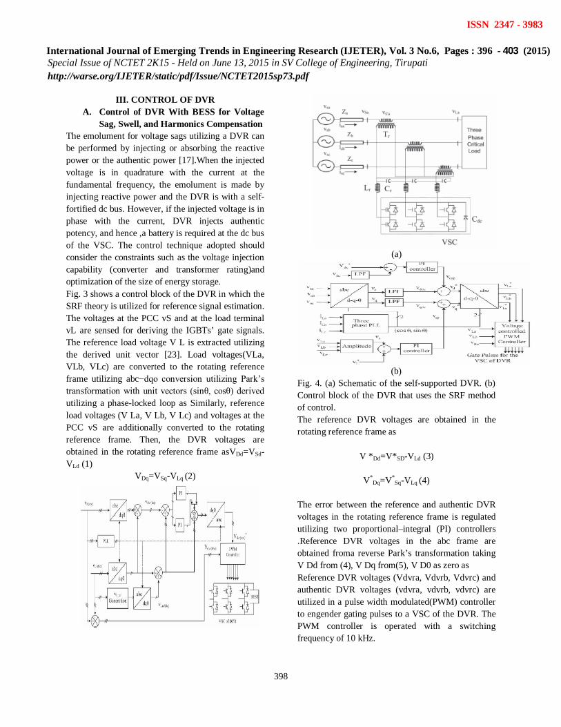
Sag, Swell, and Harmonics Compensation The emolument for voltage sags utilizing a DVR can be performed by injecting or absorbing the reactive power or the authentic power [17].When the injected voltage is in quadrature with the current at the fundamental frequency, the emolument is made by injecting reactive power and the DVR is with a self-fortified dc bus. However, if the injected voltage is in phase with the current, DVR injects authentic potency, and hence ,a battery is required at the dc bus of the VSC. The control technique adopted should consider the constraints such as the voltage injection capability (converter and transformer rating)and optimization of the size of energy storage. Fig. 3 shows a control block of the DVR in which the SRF theory is utilized for reference signal estimation. The voltages at the PCC vS and at the load terminal vL are sensed for deriving the IGBTs’ gate signals. The reference load voltage V L is extracted utilizing the derived unit vector [23]. Load voltages(VLa, VLb, VLc) are converted to the rotating reference frame utilizing abc−dqo conversion utilizing Park’s transformation with unit vectors (sinθ, cosθ) derived utilizing a phase-locked loop as Similarly, reference load voltages (V La, V Lb, V Lc) and voltages at the PCC vS are additionally converted to the rotating reference frame. Then, the DVR voltages are obtained in the rotating reference frame asVDd=VSd-VLd (1)
VDq=VSq-VLq (2)
(a)
(b)
Fig. 4. (a) Schematic of the self-supported DVR. (b) Control block of the DVR that uses the SRF method of control. The reference DVR voltages are obtained in the rotating reference frame as
V *Dd=V*SD-VLd (3)
V*Dq=V*
Sq-VLq (4)
The error between the reference and authentic DVR voltages in the rotating reference frame is regulated utilizing two proportional–integral (PI) controllers .Reference DVR voltages in the abc frame are obtained froma reverse Park’s transformation taking V Dd from (4), V Dq from(5), V D0 as zero as Reference DVR voltages (Vdvra, Vdvrb, Vdvrc) and authentic DVR voltages (vdvra, vdvrb, vdvrc) are utilized in a pulse width modulated(PWM) controller to engender gating pulses to a VSC of the DVR. The PWM controller is operated with a switching frequency of 10 kHz.
International Journal of Emerging Trends in Engineering Research (IJETER), Vol. 3 No.6, Pages : 396 - 403 (2015)
Special Issue of NCTET 2K15 - Held on June 13, 2015 in SV College of Engineering, Tirupati http://warse.org/IJETER/static/pdf/Issue/NCTET2015sp73.pdf
399
ISSN 2347 - 3983
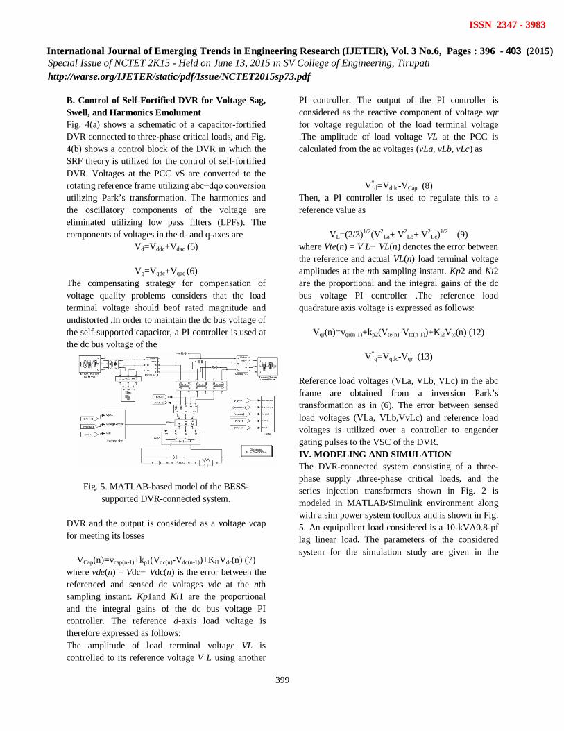
B. Control of Self-Fortified DVR for Voltage Sag, Swell, and Harmonics Emolument Fig. 4(a) shows a schematic of a capacitor-fortified DVR connected to three-phase critical loads, and Fig. 4(b) shows a control block of the DVR in which the SRF theory is utilized for the control of self-fortified DVR. Voltages at the PCC vS are converted to the rotating reference frame utilizing abc−dqo conversion utilizing Park’s transformation. The harmonics and the oscillatory components of the voltage are eliminated utilizing low pass filters (LPFs). The components of voltages in the d- and q-axes are
Vd=Vddc+Vdac (5)
Vq=Vqdc+Vqac (6) The compensating strategy for compensation of voltage quality problems considers that the load terminal voltage should beof rated magnitude and undistorted .In order to maintain the dc bus voltage of the self-supported capacitor, a PI controller is used at the dc bus voltage of the
Fig. 5. MATLAB-based model of the BESS-supported DVR-connected system.
DVR and the output is considered as a voltage vcap for meeting its losses
VCap(n)=vcap(n-1)+kp1(Vdc(n)-Vdc(n-1))+Ki1Vdc(n) (7)
where vde(n) = Vdc− Vdc(n) is the error between the referenced and sensed dc voltages vdc at the nth sampling instant. Kp1and Ki1 are the proportional and the integral gains of the dc bus voltage PI controller. The reference d-axis load voltage is therefore expressed as follows: The amplitude of load terminal voltage VL is controlled to its reference voltage V L using another
PI controller. The output of the PI controller is considered as the reactive component of voltage vqr for voltage regulation of the load terminal voltage .The amplitude of load voltage VL at the PCC is calculated from the ac voltages (vLa, vLb, vLc) as
V*
d=Vddc-VCap (8) Then, a PI controller is used to regulate this to a reference value as
VL=(2/3)1/2(V2
La+ V2Lb+ V2
Lc)1/2 (9) where Vte(n) = V L− VL(n) denotes the error between the reference and actual VL(n) load terminal voltage amplitudes at the nth sampling instant. Kp2 and Ki2 are the proportional and the integral gains of the dc bus voltage PI controller .The reference load quadrature axis voltage is expressed as follows:
Vqr(n)=vqr(n-1)+kp2(Vte(n)-Vtc(n-1))+Ki2Vtc(n) (12)
V*q=Vqdc-Vqr (13)
Reference load voltages (VLa, VLb, VLc) in the abc frame are obtained from a inversion Park’s transformation as in (6). The error between sensed load voltages (VLa, VLb,VvLc) and reference load voltages is utilized over a controller to engender gating pulses to the VSC of the DVR. IV. MODELING AND SIMULATION The DVR-connected system consisting of a three-phase supply ,three-phase critical loads, and the series injection transformers shown in Fig. 2 is modeled in MATLAB/Simulink environment along with a sim power system toolbox and is shown in Fig. 5. An equipollent load considered is a 10-kVA0.8-pf lag linear load. The parameters of the considered system for the simulation study are given in the
International Journal of Emerging Trends in Engineering Research (IJETER), Vol. 3 No.6, Pages : 396 - 403 (2015)
Special Issue of NCTET 2K15 - Held on June 13, 2015 in SV College of Engineering, Tirupati http://warse.org/IJETER/static/pdf/Issue/NCTET2015sp73.pdf
400
ISSN 2347 - 3983
Appendix.
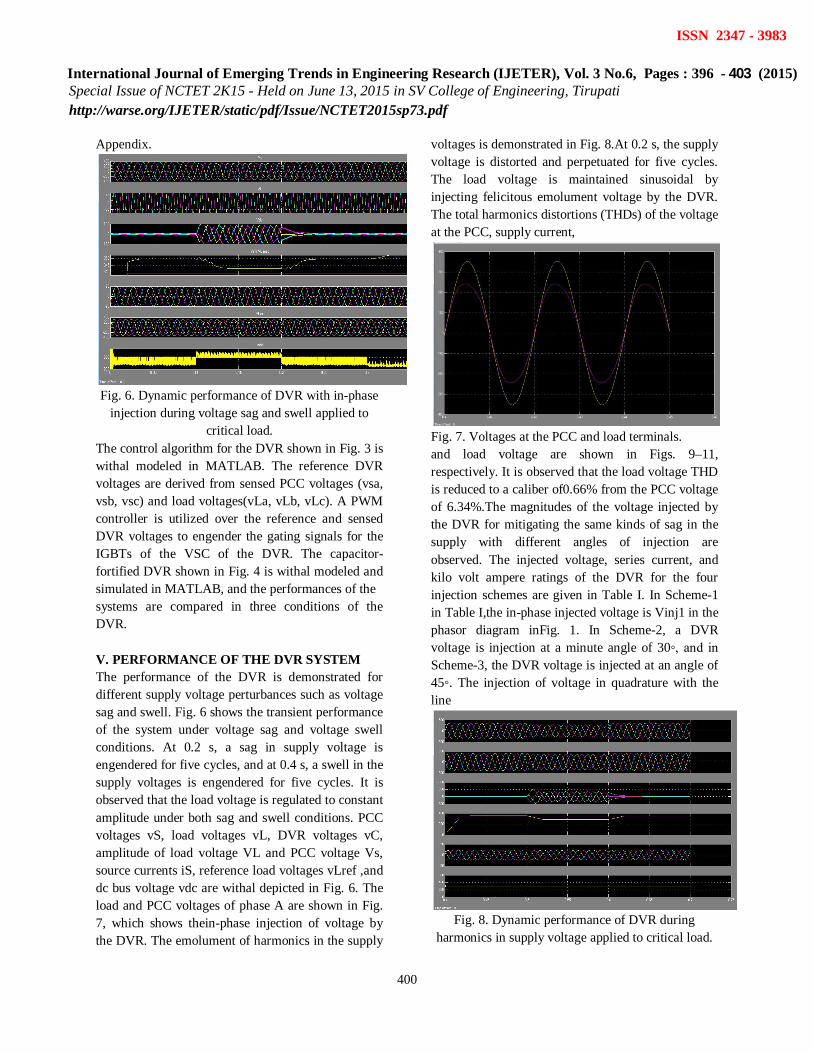
Fig. 6. Dynamic performance of DVR with in-phase
injection during voltage sag and swell applied to critical load.
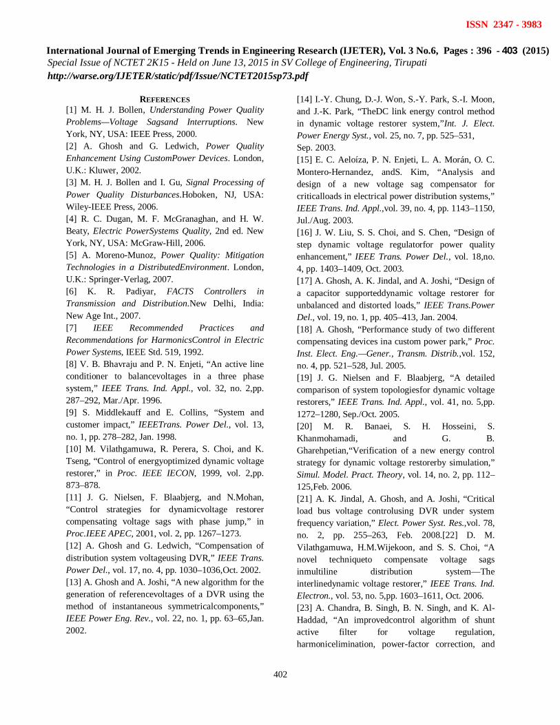
The control algorithm for the DVR shown in Fig. 3 is withal modeled in MATLAB. The reference DVR voltages are derived from sensed PCC voltages (vsa, vsb, vsc) and load voltages(vLa, vLb, vLc). A PWM controller is utilized over the reference and sensed DVR voltages to engender the gating signals for the IGBTs of the VSC of the DVR. The capacitor-fortified DVR shown in Fig. 4 is withal modeled and simulated in MATLAB, and the performances of the systems are compared in three conditions of the DVR. V. PERFORMANCE OF THE DVR SYSTEM The performance of the DVR is demonstrated for different supply voltage perturbances such as voltage sag and swell. Fig. 6 shows the transient performance of the system under voltage sag and voltage swell conditions. At 0.2 s, a sag in supply voltage is engendered for five cycles, and at 0.4 s, a swell in the supply voltages is engendered for five cycles. It is observed that the load voltage is regulated to constant amplitude under both sag and swell conditions. PCC voltages vS, load voltages vL, DVR voltages vC, amplitude of load voltage VL and PCC voltage Vs, source currents iS, reference load voltages vLref ,and dc bus voltage vdc are withal depicted in Fig. 6. The load and PCC voltages of phase A are shown in Fig. 7, which shows thein-phase injection of voltage by the DVR. The emolument of harmonics in the supply
voltages is demonstrated in Fig. 8.At 0.2 s, the supply voltage is distorted and perpetuated for five cycles. The load voltage is maintained sinusoidal by injecting felicitous emolument voltage by the DVR. The total harmonics distortions (THDs) of the voltage at the PCC, supply current,
Fig. 7. Voltages at the PCC and load terminals. and load voltage are shown in Figs. 9–11, respectively. It is observed that the load voltage THD is reduced to a caliber of0.66% from the PCC voltage of 6.34%.The magnitudes of the voltage injected by the DVR for mitigating the same kinds of sag in the supply with different angles of injection are observed. The injected voltage, series current, and kilo volt ampere ratings of the DVR for the four injection schemes are given in Table I. In Scheme-1 in Table I,the in-phase injected voltage is Vinj1 in the phasor diagram inFig. 1. In Scheme-2, a DVR voltage is injection at a minute angle of 30◦, and in Scheme-3, the DVR voltage is injected at an angle of 45◦. The injection of voltage in quadrature with the line
Fig. 8. Dynamic performance of DVR during
harmonics in supply voltage applied to critical load.

International Journal of Emerging Trends in Engineering Research (IJETER), Vol. 3 No.6, Pages : 396 - 403 (2015)
Special Issue of NCTET 2K15 - Held on June 13, 2015 in SV College of Engineering, Tirupati http://warse.org/IJETER/static/pdf/Issue/NCTET2015sp73.pdf
401
ISSN 2347 - 3983
Fig. 9. PCC voltage and harmonic spectrum during
the disturbance.
Fig. 10. Supply current and harmonic spectrum
during the disturbance.
TABLE I COMPARISON OF DVR RATING FOR SAG
MITIGATION
current is in Scheme-4. The required rating of emolument of the same utilizing Scheme-1 is much less than that of Scheme-4.The performance of the self-fortified DVR (Scheme-4) for emolument of voltage sag is shown in Fig. 12(a) and that of a voltage swell is shown in Fig. 12(b). It is observed that the injected voltage is in quadrature with the supply current ,and hence, a capacitor can fortify the dc bus of the DVR .However, the injected voltage is higher compared with an in phase injected voltage (Scheme-1).
(a)
(b)
Fig. 11. Dynamic performance of the capacitor-supported DVR during (a) voltage sag and (b) voltage swell applied to critical load.
VI. CONCLUSION The operation of a DVR has been demonstrated with an incipient control technique utilizing sundry voltage injection schemes. A comparison of the performance of the DVR with different schemes has been performed with a reduced-rating VSC, including a capacitor-fortified DVR. The reference load voltage has been estimated utilizing the method of unit vectors, and the control of DVR has been achieved, which minimizes the error of voltage injection. The SRF theory has been utilized for estimating the reference DVR voltages. It is concluded that the voltage injection in-phase with the PCC voltage results in minimum rating of DVR but at the cost of an energy source atits dc bus.
International Journal of Emerging Trends in Engineering Research (IJETER), Vol. 3 No.6, Pages : 396 - 403 (2015)
Special Issue of NCTET 2K15 - Held on June 13, 2015 in SV College of Engineering, Tirupati http://warse.org/IJETER/static/pdf/Issue/NCTET2015sp73.pdf
402
ISSN 2347 - 3983
REFERENCES [1] M. H. J. Bollen, Understanding Power Quality Problems—Voltage Sagsand Interruptions. New York, NY, USA: IEEE Press, 2000. [2] A. Ghosh and G. Ledwich, Power Quality Enhancement Using CustomPower Devices. London, U.K.: Kluwer, 2002. [3] M. H. J. Bollen and I. Gu, Signal Processing of Power Quality Disturbances.Hoboken, NJ, USA: Wiley-IEEE Press, 2006. [4] R. C. Dugan, M. F. McGranaghan, and H. W. Beaty, Electric PowerSystems Quality, 2nd ed. New York, NY, USA: McGraw-Hill, 2006. [5] A. Moreno-Munoz, Power Quality: Mitigation Technologies in a DistributedEnvironment. London, U.K.: Springer-Verlag, 2007. [6] K. R. Padiyar, FACTS Controllers in Transmission and Distribution.New Delhi, India: New Age Int., 2007. [7] IEEE Recommended Practices and Recommendations for HarmonicsControl in Electric Power Systems, IEEE Std. 519, 1992. [8] V. B. Bhavraju and P. N. Enjeti, “An active line conditioner to balancevoltages in a three phase system,” IEEE Trans. Ind. Appl., vol. 32, no. 2,pp. 287–292, Mar./Apr. 1996. [9] S. Middlekauff and E. Collins, “System and customer impact,” IEEETrans. Power Del., vol. 13, no. 1, pp. 278–282, Jan. 1998. [10] M. Vilathgamuwa, R. Perera, S. Choi, and K. Tseng, “Control of energyoptimized dynamic voltage restorer,” in Proc. IEEE IECON, 1999, vol. 2,pp. 873–878. [11] J. G. Nielsen, F. Blaabjerg, and N.Mohan, “Control strategies for dynamicvoltage restorer compensating voltage sags with phase jump,” in Proc.IEEE APEC, 2001, vol. 2, pp. 1267–1273. [12] A. Ghosh and G. Ledwich, “Compensation of distribution system voltageusing DVR,” IEEE Trans. Power Del., vol. 17, no. 4, pp. 1030–1036,Oct. 2002. [13] A. Ghosh and A. Joshi, “A new algorithm for the generation of referencevoltages of a DVR using the method of instantaneous symmetricalcomponents,” IEEE Power Eng. Rev., vol. 22, no. 1, pp. 63–65,Jan. 2002.
[14] I.-Y. Chung, D.-J. Won, S.-Y. Park, S.-I. Moon, and J.-K. Park, “TheDC link energy control method in dynamic voltage restorer system,”Int. J. Elect. Power Energy Syst., vol. 25, no. 7, pp. 525–531, Sep. 2003. [15] E. C. Aeloíza, P. N. Enjeti, L. A. Morán, O. C. Montero-Hernandez, andS. Kim, “Analysis and design of a new voltage sag compensator for criticalloads in electrical power distribution systems,” IEEE Trans. Ind. Appl.,vol. 39, no. 4, pp. 1143–1150, Jul./Aug. 2003. [16] J. W. Liu, S. S. Choi, and S. Chen, “Design of step dynamic voltage regulatorfor power quality enhancement,” IEEE Trans. Power Del., vol. 18,no. 4, pp. 1403–1409, Oct. 2003. [17] A. Ghosh, A. K. Jindal, and A. Joshi, “Design of a capacitor supporteddynamic voltage restorer for unbalanced and distorted loads,” IEEE Trans.Power Del., vol. 19, no. 1, pp. 405–413, Jan. 2004. [18] A. Ghosh, “Performance study of two different compensating devices ina custom power park,” Proc. Inst. Elect. Eng.—Gener., Transm. Distrib.,vol. 152, no. 4, pp. 521–528, Jul. 2005. [19] J. G. Nielsen and F. Blaabjerg, “A detailed comparison of system topologiesfor dynamic voltage restorers,” IEEE Trans. Ind. Appl., vol. 41, no. 5,pp. 1272–1280, Sep./Oct. 2005. [20] M. R. Banaei, S. H. Hosseini, S. Khanmohamadi, and G. B. Gharehpetian,“Verification of a new energy control strategy for dynamic voltage restorerby simulation,” Simul. Model. Pract. Theory, vol. 14, no. 2, pp. 112–125,Feb. 2006. [21] A. K. Jindal, A. Ghosh, and A. Joshi, “Critical load bus voltage controlusing DVR under system frequency variation,” Elect. Power Syst. Res.,vol. 78, no. 2, pp. 255–263, Feb. 2008.[22] D. M. Vilathgamuwa, H.M.Wijekoon, and S. S. Choi, “A novel techniqueto compensate voltage sags inmultiline distribution system—The interlinedynamic voltage restorer,” IEEE Trans. Ind. Electron., vol. 53, no. 5,pp. 1603–1611, Oct. 2006. [23] A. Chandra, B. Singh, B. N. Singh, and K. Al-Haddad, “An improvedcontrol algorithm of shunt active filter for voltage regulation, harmonicelimination, power-factor correction, and

International Journal of Emerging Trends in Engineering Research (IJETER), Vol. 3 No.6, Pages : 396 - 403 (2015)
Special Issue of NCTET 2K15 - Held on June 13, 2015 in SV College of Engineering, Tirupati http://warse.org/IJETER/static/pdf/Issue/NCTET2015sp73.pdf
403
ISSN 2347 - 3983
balancing of nonlinear loads,”IEEE Trans. Power Electron., vol. 15, no. 3, pp. 495–507, May 2000. [24] A. Y. Goharrizi, S. H. Hosseini, M. Sabahi, and G. B. Gharehpetian,“Three-phase HFL-DVR with independently controlled phases,” IEEETrans. Power Electron., vol. 27, no. 4, pp. 1706–1718, Apr. 2012.
Mr.T.Venkateswarlu currently pursuing his post graduate degree from Jawaharlal Nehru technological university in electrical and electronics engineering with specialization in power electronics and electrical drives. His areas of interest include renewable energy sources, power quality and advanced power controlling techniques
Mr.B.ramesh received M.Tech from sri venkatesa perumal college of engineering and technology,puttur,Andhra Pradesh,India.He is presently working as assistant professor in siddartha institute of science and technology,puttur.his research interest areas are renewable energy sources and facts devices


![[inria-00288415, v2] Improvement of Reduced Order Modeling ...mbergman/PDF/Research...Key-words: Proper Orthogonal Decomposition, Reduced Order Model, Sta - bilization, Functional](https://img.pdfslide.net/doc/110x75/61428609d9e4dc11f47f1b06/inria-00288415-v2-improvement-of-reduced-order-modeling-mbergmanpdfresearch.jpg)