Embed Size (px)
Citation preview
General rights Copyright and moral rights for the publications made accessible in the public portal are retained by the authors and/or other copyright owners and it is a condition of accessing publications that users recognise and abide by the legal requirements associated with these rights.
Users may download and print one copy of any publication from the public portal for the purpose of private study or research.
You may not further distribute the material or use it for any profit-making activity or commercial gain
You may freely distribute the URL identifying the publication in the public portal If you believe that this document breaches copyright please contact us providing details, and we will remove access to the work immediately and investigate your claim.
Downloaded from orbit.dtu.dk on: Oct 26, 2021
Enhancing the Robustness of Brittle Solid Oxide Cell Stack Components
Frandsen, Henrik Lund; Ritucci, I.; Khajavi, P.; Talic, B.; Kiebach, R.; Hendriksen, P. V.
Published in:E C S Transactions
Link to article, DOI:10.1149/09101.2201ecst
Publication date:2019
Document VersionPeer reviewed version
Link back to DTU Orbit
Citation (APA):Frandsen, H. L., Ritucci, I., Khajavi, P., Talic, B., Kiebach, R., & Hendriksen, P. V. (2019). Enhancing theRobustness of Brittle Solid Oxide Cell Stack Components. E C S Transactions, 91(1), 2201-2211 .https://doi.org/10.1149/09101.2201ecst
Enhancing the Robustness of Brittle Solid Oxide Cell Stack Components H. L. Frandsena, I. Rituccia, P. Khajavia, B. Talica, R. Kiebacha, P. V. Hendriksena
a Department of Energy Conversion and Storage, Technical University of Denmark,
Denmark
Abstract For long-term durability and robustness to withstand thermal cycles, the planar solid oxide cell (SOC) stack technologies are challenged by the use of brittle components. With the current trend of increasing the footprint of the SOC stacks, even larger thermal gradients and thermal stresses can be expected. In this overview paper, we present recent advances from our group on improving the fracture energy of three critical materials/interfaces. The fracture energy of the fuel electrode support is increased by ~50 % by tailoring composition and further optimizing the phase transformation toughening. The fracture energy of the air-side contact layer is increased by a factor of ~10 by using metallic pre-cursors that are transformed to spinels through in-situ reactive oxidative bonding. Finally, the fracture energy of the seal-interconnect interface is improved by a factor of 5 by combining an optimized sealing glass with aluminum based coatings for the interconnect.
Introduction
In planar Solid Oxide Cell (SOC) stack technology the cells are either electrolyte or fuel electrode supported. By introducing an extra layer on the fuel electrode side, beyond the electrochemical active layer, the properties of the two fuel electrode layers can be optimized separately. The resistance towards in-plane crack propagation can thus be optimized by structural and material optimization of the separate fuel electrode support layer. This layer should allow for gas diffusion and conduction of electrons, but has no electrochemical function, as this is handled by the active layer close to the electrolyte. The current state of the art for the support layer is a cermet of Ni and three mol% yttria doped zirconia (3YSZ) (1,2), which is considerably tougher (+ 60-70 %) than 8 mol% yttria doped zirconia (8YSZ) (3,4). The increased fracture toughness of 3YSZ stems from the martensitic phase transformation of metastable tetragonal zirconia to monoclinic zirconia. At crack propagation the high tensile stresses at the crack tip trigger the transformation, thereby inducing a volumetric expansion at the crack tip and in the wake of the crack, shielding the crack tip. The effectiveness of this toughening mechanism can be optimized by enhancing the transformability, which depends primarily on the amount of stabilizer, grain size and temperature, but also on porosity of the support to a small extend (5). Lowering the amount of yttrium substitution (serving as a stabilizer) might increase the fracture toughness, but the stability towards low and high temperature hygrothermal degradation is critically decreased (6). Here, we will present how co-doping the zirconia with cerium and yttrium can increase the fracture energy of the fuel electrode support by ~50 % compared to the state-of-the-art NiO-3YSZ, without compromising the hygrothermal stability.
Other critical interfaces in planar SOC stacks are those between the cell and the interconnect. On the fuel electrode side Ni meshes or foams can be used to ensure good adhesion and current distribution (7–9). However, the adherence between the oxygen electrode and the interconnect is more challenging. Conventionally, contacting on the oxygen side is established by use of perovskite oxide contact layers, which are made of a composition similar to that of the oxygen electrode itself. This layer can be sintered in-situ during stack assembly to ensure a good contact to both the cell and the interconnect. The challenge is however to have sufficient sintering activity, as the temperature and hold time is limited by the other components of the SOC stack, primarily the metallic components (10). Lowering the grain size and addition of sintering aids have been attempted, with limited success (11), (12). A loss of contact between the interconnect and oxygen electrode will result in redirection of current in less conductive materials, ohmic heating, and possibly a progressive development of failure due to the local higher temperatures. Therefore, the robustness of the oxygen electrode contact layer is critical in the SOC stacks. Here, we show how application of reactive oxidative bonding, based on metallic pre-cursors (Cu,Co,Mn) that in-situ form a well-conducting spinel oxide (13), can enhance the fracture energy of the interface approximately by a factor of 10 as compared to the in-situ sintered perovskite type contact layers. The cells and different steel components in the planar SOC stacks are often joined by use of glass-ceramic seals. The gas tightness and integrity of the SOC stack depends critically on high robustness of the glass ceramic seals. Recently it was shown that the mechanical robustness of the sealing of SOC stacks not only depends on the glass-ceramic sealing material itself, but also on the adjacent interfaces, typically interconnect coatings and the zirconia of the cell (14). The choice of the coating material and its surface roughness significantly influences the adherence of the sealing to the steel components of the stack. Here we show how the combination of an alumina based coating and a recently developed glass ceramic (15) can increase the fracture energy of the glass ceramic joint by more than a factor of 5, as compared to the adherence between the sealing and a pre-oxidized or Mn,Co-oxide (MCO) coated steel interconnect.
Experimental
Fuel electrode support layer Yttria doped zirconia powders 8YSZ (mixture of 16 mole % YO1.5 and 84 mole % ZrO2) and 3YSZ (mixture of 6 mole % YO1.5 and 94 mole % ZrO2) were acquired from Tosoh (Japan), and a ceria-yttria co-doped zirconia (1.5CeO2 4.5YO1.5-SZ) (mixture of 4.5 mole % YO1.5, 1.5 mole % CeO2 and 94 mole % ZrO2 powder) was specifically manufactured by Nanoe (France). The choice of the composition for the latter was found through a careful optimization, where the highest possible transformability is found while ensuring stability during processing (milling, sintering etc.) (16). The zirconia powders were mixed with NiO in the ratio of 45 wt% and 55 wt%, respectively. The fuel electrode supports were shaped by tape casting, such that they after sintering (~1315°C) had an average thickness of 200-300 μm. The sintered supports were cut by a laser into samples
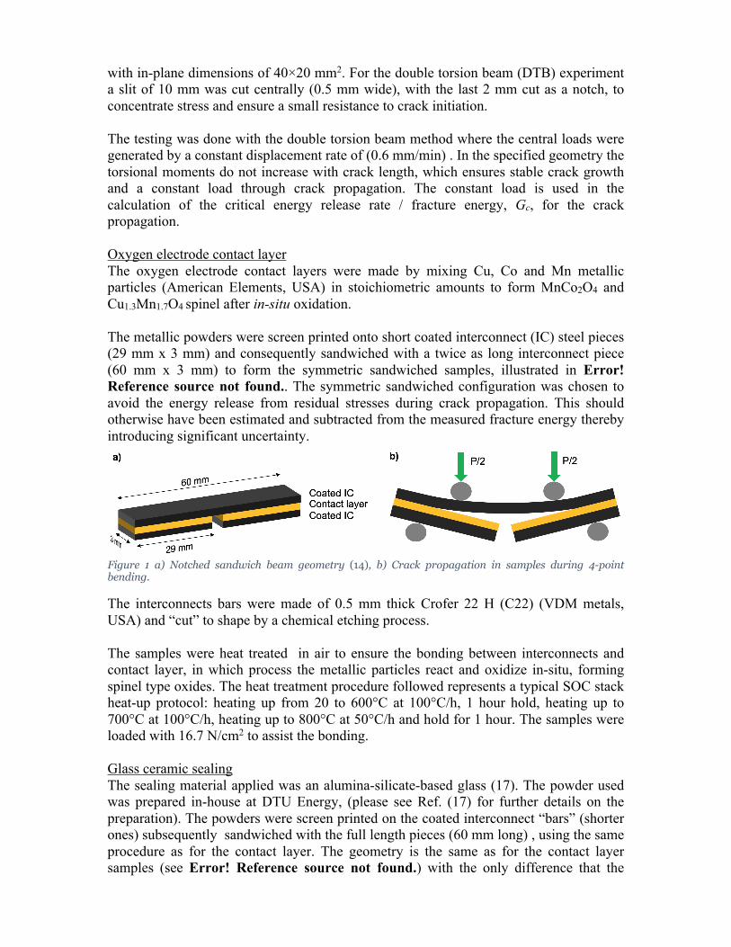
with in-plane dimensions of 40×20 mm2. For the double torsion beam (DTB) experiment a slit of 10 mm was cut centrally (0.5 mm wide), with the last 2 mm cut as a notch, to concentrate stress and ensure a small resistance to crack initiation. The testing was done with the double torsion beam method where the central loads were generated by a constant displacement rate of (0.6 mm/min) . In the specified geometry the torsional moments do not increase with crack length, which ensures stable crack growth and a constant load through crack propagation. The constant load is used in the calculation of the critical energy release rate / fracture energy, Gc, for the crack propagation. Oxygen electrode contact layer The oxygen electrode contact layers were made by mixing Cu, Co and Mn metallic particles (American Elements, USA) in stoichiometric amounts to form MnCo2O4 and Cu1.3Mn1.7O4 spinel after in-situ oxidation. The metallic powders were screen printed onto short coated interconnect (IC) steel pieces (29 mm x 3 mm) and consequently sandwiched with a twice as long interconnect piece (60 mm x 3 mm) to form the symmetric sandwiched samples, illustrated in Error! Reference source not found.. The symmetric sandwiched configuration was chosen to avoid the energy release from residual stresses during crack propagation. This should otherwise have been estimated and subtracted from the measured fracture energy thereby introducing significant uncertainty.
Figure 1 a) Notched sandwich beam geometry (14), b) Crack propagation in samples during 4-point bending.
The interconnects bars were made of 0.5 mm thick Crofer 22 H (C22) (VDM metals, USA) and “cut” to shape by a chemical etching process. The samples were heat treated in air to ensure the bonding between interconnects and contact layer, in which process the metallic particles react and oxidize in-situ, forming spinel type oxides. The heat treatment procedure followed represents a typical SOC stack heat-up protocol: heating up from 20 to 600°C at 100°C/h, 1 hour hold, heating up to 700°C at 100°C/h, heating up to 800°C at 50°C/h and hold for 1 hour. The samples were loaded with 16.7 N/cm2 to assist the bonding. Glass ceramic sealing The sealing material applied was an alumina-silicate-based glass (17). The powder used was prepared in-house at DTU Energy, (please see Ref. (17) for further details on the preparation). The powders were screen printed on the coated interconnect “bars” (shorter ones) subsequently sandwiched with the full length pieces (60 mm long) , using the same procedure as for the contact layer. The geometry is the same as for the contact layer samples (see Error! Reference source not found.) with the only difference that the
contact layer is replaced by glass. During heat treatment the glass densifies, crystalizes and bonds with the adjacent surfaces (14). The samples are heat treated with an optimized heating profile (17), which corresponds to the one used for the heat treatment of the contact layers. The interconnects bars were made of 0.5 mm thick Crofer 22 H (VDM metals, USA) “cut” to shape by a chemical etching. The interconnects were coated in-house with an alumina coating, where aluminum metallic powders are deposited on the steel, and heat treated to diffuse and partly alloy with the steel substrate and oxidize to form a thin (~1 µm) alumina (Al2O3) coating on the surface (18,19).
Analysis
Double torsion beam test The fracture energy for the double torsion beam test was deduced from the load according to (20):
𝐺! = #𝑃𝑊"𝑡# '
# 3(1 + 𝜈)(1 − 𝜈#)𝑊𝜓𝐸
(1)
where P is the applied load, Wm is the moment arm, W and t are the width and thickness of the specimen, respectively. E and ν are Young’s modulus and the Poisson ratio, respectively. ψ(t,W) is a correction factor for specimen thickness (21): 𝜓 = 1 − 1.2604:𝑡 𝑊; < + 2.4:𝑡 𝑊; <exp(−𝑊𝜋 2𝑡; ) (2) Four-point bending using Charalambides geometry The critical energy release rate, 𝐺!, in the applied four point bending tests (used here for the IC/contact layer and IC/sealing samples) is determined by (22):
𝐺! =𝑀$#(1 − 𝜈##)2𝐸#
#1𝐼#−1𝐼!'
(3)
where 𝐸#, 𝜈# and 𝐼#, are the Young’s modulus, Poisson’s ratio and second moment of area of the through-going substrate of Crofer 22 APU, respectively. The indexes 2 and d here refer to that of the adhering layer (glass-ceramic layer /contact layer), and the substrate (long metal slip), respectively. 𝐼! is the combined second moment of area of the stiffeners and the adhering layer. The bending moment, Mb, at the load plateau, P, between the inner pins in the four-point bending is:
𝑀$ =𝑃𝑙2𝑏
(4)
where 𝑙 is the distance between the outer and inner roll, and 𝑏 is the sample width, 𝑙 is 12.5 mm and 𝑏 is 3.0 mm. The second moments of areas are calculated as:
𝐼# =ℎ#%
12 (5)
where ℎ# is the thickness of the substrate. And 𝐼! as:
𝐼! =ℎ"#
3+ 𝜅
ℎ$#
3+ µ )
ℎ%#
3+ ℎ%# ℎ$ + ℎ$"ℎ%* −
,ℎ"" − 𝜅ℎ$" − µ(ℎ%" + 2ℎ$ℎ%)0"
4(ℎ" + 𝜅ℎ$ + µℎ%)
(6)
where index 1 refers to the stiffener (the short metal strips). 𝜅 is the ratio between the stiffness of the substrate and the stiffener (which are identical here):
𝜅 =
𝐸&(1 − 𝑣##)𝐸#(1 − 𝑣&#)
(7)
And µ is the ratio between the stiffness of the substrate and the adhering layer
µ =𝐸'(1 − 𝑣##)𝐸#(1 − 𝑣'#)
(8)
Results and discussion
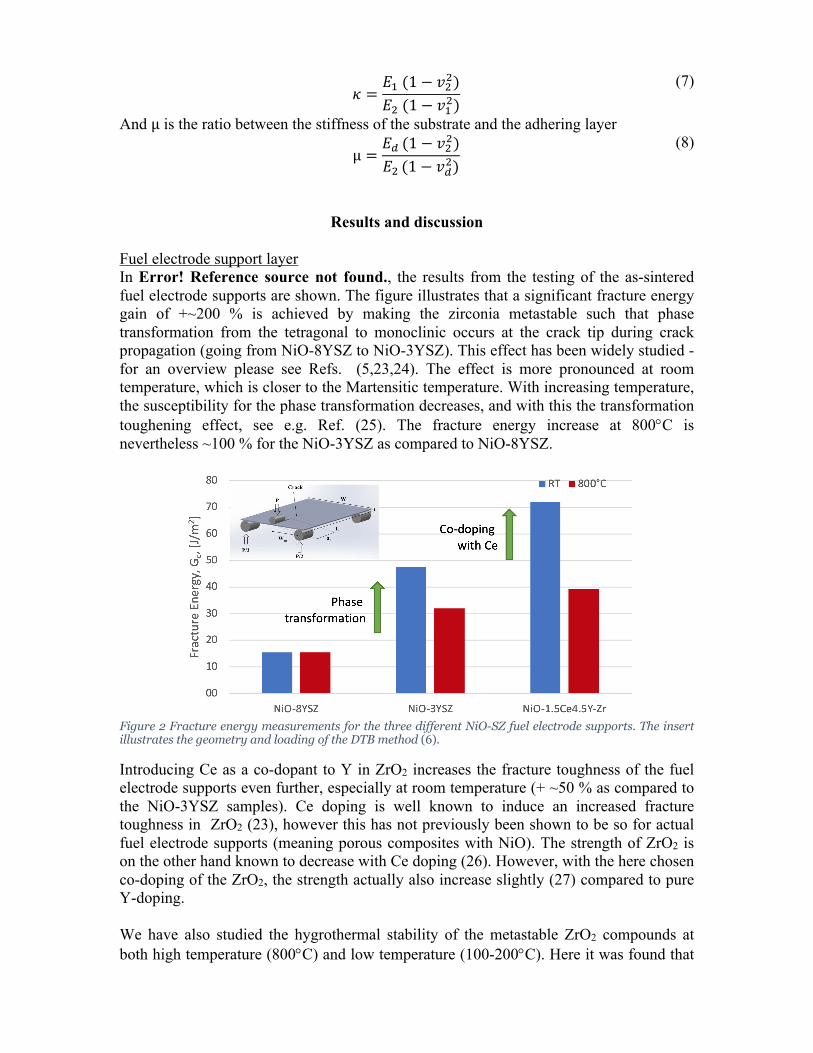
Fuel electrode support layer In Error! Reference source not found., the results from the testing of the as-sintered fuel electrode supports are shown. The figure illustrates that a significant fracture energy gain of +~200 % is achieved by making the zirconia metastable such that phase transformation from the tetragonal to monoclinic occurs at the crack tip during crack propagation (going from NiO-8YSZ to NiO-3YSZ). This effect has been widely studied - for an overview please see Refs. (5,23,24). The effect is more pronounced at room temperature, which is closer to the Martensitic temperature. With increasing temperature, the susceptibility for the phase transformation decreases, and with this the transformation toughening effect, see e.g. Ref. (25). The fracture energy increase at 800°C is nevertheless ~100 % for the NiO-3YSZ as compared to NiO-8YSZ.
Figure 2 Fracture energy measurements for the three different NiO-SZ fuel electrode supports. The insert illustrates the geometry and loading of the DTB method (6).
Introducing Ce as a co-dopant to Y in ZrO2 increases the fracture toughness of the fuel electrode supports even further, especially at room temperature (+ ~50 % as compared to the NiO-3YSZ samples). Ce doping is well known to induce an increased fracture toughness in ZrO2 (23), however this has not previously been shown to be so for actual fuel electrode supports (meaning porous composites with NiO). The strength of ZrO2 is on the other hand known to decrease with Ce doping (26). However, with the here chosen co-doping of the ZrO2, the strength actually also increase slightly (27) compared to pure Y-doping. We have also studied the hygrothermal stability of the metastable ZrO2 compounds at both high temperature (800°C) and low temperature (100-200°C). Here it was found that
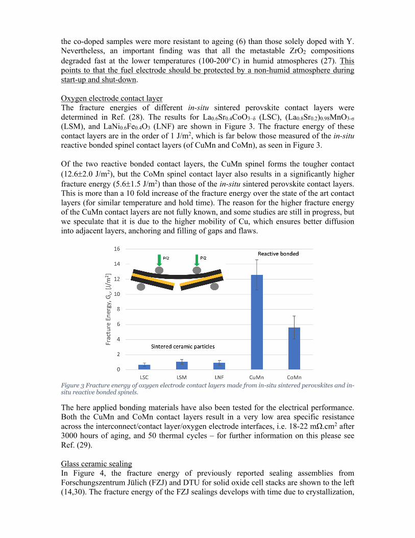
the co-doped samples were more resistant to ageing (6) than those solely doped with Y. Nevertheless, an important finding was that all the metastable ZrO2 compositions degraded fast at the lower temperatures (100-200°C) in humid atmospheres (27). This points to that the fuel electrode should be protected by a non-humid atmosphere during start-up and shut-down. Oxygen electrode contact layer The fracture energies of different in-situ sintered perovskite contact layers were determined in Ref. (28). The results for La0.6Sr0.4CoO3–δ (LSC), (La0.8Sr0.2)0.98MnO3-σ (LSM), and LaNi0.6Fe0.4O3 (LNF) are shown in Figure 3. The fracture energy of these contact layers are in the order of 1 J/m2, which is far below those measured of the in-situ reactive bonded spinel contact layers (of CuMn and CoMn), as seen in Figure 3. Of the two reactive bonded contact layers, the CuMn spinel forms the tougher contact (12.6±2.0 J/m2), but the CoMn spinel contact layer also results in a significantly higher fracture energy (5.6±1.5 J/m2) than those of the in-situ sintered perovskite contact layers. This is more than a 10 fold increase of the fracture energy over the state of the art contact layers (for similar temperature and hold time). The reason for the higher fracture energy of the CuMn contact layers are not fully known, and some studies are still in progress, but we speculate that it is due to the higher mobility of Cu, which ensures better diffusion into adjacent layers, anchoring and filling of gaps and flaws.
Figure 3 Fracture energy of oxygen electrode contact layers made from in-situ sintered perovskites and in-situ reactive bonded spinels.
The here applied bonding materials have also been tested for the electrical performance. Both the CuMn and CoMn contact layers result in a very low area specific resistance across the interconnect/contact layer/oxygen electrode interfaces, i.e. 18-22 mΩ.cm2 after 3000 hours of aging, and 50 thermal cycles – for further information on this please see Ref. (29). Glass ceramic sealing In Figure 4, the fracture energy of previously reported sealing assemblies from Forschungszentrum Jülich (FZJ) and DTU for solid oxide cell stacks are shown to the left (14,30). The fracture energy of the FZJ sealings develops with time due to crystallization,
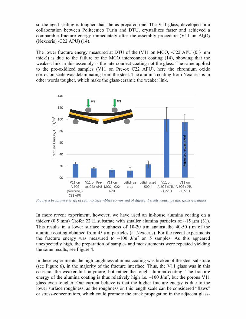
so the aged sealing is tougher than the as prepared one. The V11 glass, developed in a collaboration between Politecnico Turin and DTU, crystallizes faster and achieved a comparable fracture energy immediately after the assembly procedure (V11 on Al2O3 (Nexceris) -C22 APU) (14). The lower fracture energy measured at DTU of the (V11 on MCO, -C22 APU (0.3 mm thick)) is due to the failure of the MCO interconnect coating (14), showing that the weakest link in this assembly is the interconnect coating not the glass. The same applied to the pre-oxidized samples (V11 on Pre-ox C22 APU), here the chromium oxide corrosion scale was delaminating from the steel. The alumina coating from Nexceris is in other words tougher, which make the glass-ceramic the weaker link.
Figure 4 Fracture energy of sealing assemblies comprised of different steels, coatings and glass-ceramics.
In more recent experiment, however, we have used an in-house alumina coating on a thicker (0.5 mm) Crofer 22 H substrate with smaller alumina particles of ~15 µm (31). This results in a lower surface roughness of 10-20 µm against the 40-50 µm of the alumina coating obtained from 45 µm particles (at Nexceris). For the recent experiments the fracture energy was measured to ~100 J/m2 on 5 samples. As this appeared unexpectedly high, the preparation of samples and measurements were repeated yielding the same results, see Figure 4. In these experiments the high toughness alumina coating was broken of the steel substrate (see Figure 6), in the majority of the fracture interface. Thus, the V11 glass was in this case not the weaker link anymore, but rather the tough alumina coating. The fracture energy of the alumina coating is thus relatively high i.e. ~100 J/m2, but the porous V11 glass even tougher. Our current believe is that the higher fracture energy is due to the lower surface roughness, as the roughness on this length scale can be considered “flaws” or stress-concentrators, which could promote the crack propagation in the adjacent glass-
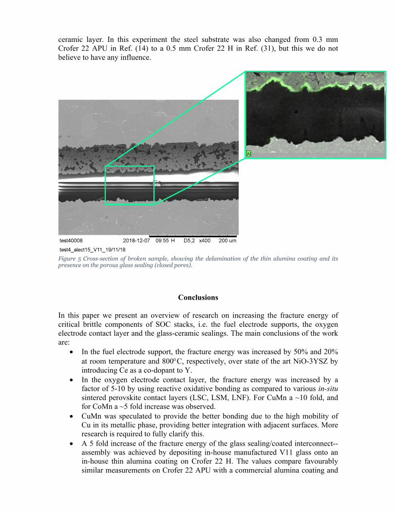
ceramic layer. In this experiment the steel substrate was also changed from 0.3 mm Crofer 22 APU in Ref. (14) to a 0.5 mm Crofer 22 H in Ref. (31), but this we do not believe to have any influence.
Figure 5 Cross-section of broken sample, showing the delamination of the thin alumina coating and its presence on the porous glass sealing (closed pores).
Conclusions
In this paper we present an overview of research on increasing the fracture energy of critical brittle components of SOC stacks, i.e. the fuel electrode supports, the oxygen electrode contact layer and the glass-ceramic sealings. The main conclusions of the work are:
• In the fuel electrode support, the fracture energy was increased by 50% and 20% at room temperature and 800°C, respectively, over state of the art NiO-3YSZ by introducing Ce as a co-dopant to Y.
• In the oxygen electrode contact layer, the fracture energy was increased by a factor of 5-10 by using reactive oxidative bonding as compared to various in-situ sintered perovskite contact layers (LSC, LSM, LNF). For CuMn a ~10 fold, and for CoMn a ~5 fold increase was observed.
• CuMn was speculated to provide the better bonding due to the high mobility of Cu in its metallic phase, providing better integration with adjacent surfaces. More research is required to fully clarify this.
• A 5 fold increase of the fracture energy of the glass sealing/coated interconnect--assembly was achieved by depositing in-house manufactured V11 glass onto an in-house thin alumina coating on Crofer 22 H. The values compare favourably similar measurements on Crofer 22 APU with a commercial alumina coating and
the same glass and with measurements from Forschungszentrum Jülich (30) on comparable sealing/steel-joints.
• The reason behind the significant gain of fracture energy was speculated to be the controlled surface roughness. More research is needed to fully clarify this.
Acknowledgements
This work has been supported by LOWCOST-IC, a project under the Fuel Cells and Hydrogen 2 Joint Undertaking (JU), grant agreement No 826323. The JU receives support from the European Union’s Horizon 2020 research and innovation programme and Denmark, France, Austria, Belgium, Sweden, Germany, Italy. The work was also supported by “SYNFUEL”, a project under Innovation fund, Denmark, project No. 4106-00006B.
References
1. H. L. Frandsen, T. Ramos, A. Faes, M. Pihlatie, and K. Brodersen, J. Eur. Ceram. Soc., 32, 1041–1052 (2012). 2. F. Fleischhauer et al., J. Power Sources, 273, 237–243 (2015). 3. G. Pećanac, J. Wei, and J. Malzbender, J. Power Sources, 327, 629–637 (2016). 4. P. Khajavi, thesis, Technical University of Denmark (2018). 5. J. Chevalier, L. Gremillard, A. V. Virkar, and D. R. Clarke, J. Am. Ceram. Soc., 92, 1901–1920 (2009). 6. P. Khajavi, P. V. Hendriksen, J. Chevalier, L. Gremillard, and H. L. Frandsen, Submitted. 7. H. Simpkins, K. Haltiner, and S. Mukerjee, (2002). 8. V. Sarda et al., ECS Trans., 57, 2279–2288 (2013). 9. M. Canavar and Y. Kaplan, Int. J. Hydrogen Energy, 40, 7829–7834 (2015). 10. P. Kofstad and R. Bredesen, Solid State Ionics, 52, 69–75 (1992). 11. M. C. Tucker, L. C. DeJonghe, V. García-Negrón, R. Trejo, and E. Lara-Curzio, J. Power Sources, 239, 315–320 (2013). 12. X. Montero, F. Tietz, D. Stöver, M. Cassir, and I. Villarreal, J. Power Sources, 188, 148–155 (2009). 13. A. Petric and H. Ling, J. Am. Ceram. Soc., 90, 1515–1520 (2007). 14. I. Ritucci et al., J. Mater. Res., 1–12 (2019). 15. I. Ritucci et al., Int. J. Appl. Ceram. Technol., 1–12 (2018). 16. P. Khajavi et al., submitted. 17. I. Ritucci et al., Int. J. Appl. Ceram. Technol., 15 (2018). 18. J.-P. Choi, Y. S. Chou, and J. W. Stevenson, Reactive Air Aluminization, (2011). 19. N. J. Kidner, Alumilok TM Coatings: Enhanced High Temperature Performance for Commercial Steels. 20. D. p. Williams and A. g. Evans, J. Test. Eval., 1, 264–270 (1973). 21. E. R. Fuller Jr., An Evaluation of Double-Torsion Testing — Analysis, p. 3–18., (1979). 22. I. Hofinger, M. Oechsner, H.-A. Bahr, and M. V. Swain, Int. J. Fract., 92, 213–220 (1998). 23. R. H. J. Hannink, P. M. Kelly, and B. C. Muddle, J. Am. Ceram. Soc., 83, 461–487 (2000). 24. J. R. Kelly and I. Denry, Dent. Mater., 24, 289–98 (2008).

25. I. Denry and J. R. Kelly, Dent. Mater., 24, 299–307 (2008). 26. R. H. J. Hannink, P. M. Kelly, and B. C. Muddle, J. Am. Ceram. Soc., 83, 461–487 (2004). 27. P. Khajavi, P. V. Hendriksen, L. Gremillard, J. Chevalier, and H. L. Frandsen, Prep. 28. L. Han et al.,. 29. B. Talic, I. Ritucci, R. Kiebach, and H. L. Frandsen, in ECS Transactions, (2019). 30. J. Malzbender, R. W. Steinbrech, and L. Singheiser, J. Mater. Res., 18, 929–934 (2003). 31. I. Ritucci, B. Talic, R. Kiebach, and H. L. Frandsen,.