Embed Size (px)
Citation preview
ENHANCING VIRTUAL PROTOTYPE IN SHIP DESIGN USING
MODULAR TECHNIQUES
Olivia Chaves Marcus Nickelsen Henrique Gaspar
Federal Univ. of Itajubá (Brazil) Ålesund University College Ålesund University College
Ålesund University College
(exchange program)
Maritime Technology and Operations Maritime Technology and Operations
Larsgårdsvegen 2, 6009, Norway Larsgårdsvegen 2, 6009, Norway Larsgårdsvegen 2, 6009, Norway
[email protected] [email protected] [email protected]
KEYWORDS
Modularization, Ship design, Virtual prototype.
ABSTRACT
This paper proposes a modular approach as a technique
to enhance Virtual Prototype (VP) in conceptual ship
design. The methodology proposes a preliminary
modular ship division, which is made according to the
ship systems functionality. The modules obtained from
ship division are analyzed in relation to how they
interact among themselves (compatibility) as well as
how relevant they are for the efficient performance of a
mission (performance). An entity model is virtually
assembled and evaluated, feeding an application that is
able to simulate all possible module’s arrangements and
list the better ones regarding the customer requirements.
In doing so, we ended up having a ship modularization
methodology, an application to handle the assemble
process using VP, and a methodology to evaluate how
suitable an entity model is for accomplishing a mission.
The approach is exemplified through a preliminary
offshore support vessel case, where the methodology is
implemented in a preliminary virtual prototype
application, which enables the parameters and
requirements set, assisting the assembly process,
visualizing the modules as well as the entity, electing the
most suitable arrangement for the initial conditions
established by the user.
INTRODUCTION
The maritime offshore industry is characterized by
manufacturing highly customized vessels. Each design
is usually unique and commonly done from scratch to
the end. The level of interdependence between systems
in a vessel is too high, as they are not thought to be
anyway else (Erikstad, 2009). Once a small change in
the requirements, compromises the design of the whole
ship. For each small change, large parts of the ship have to be re-designed.
Cost-driven solutions are being studied to diminish the
design and construction time of such vessels, in special
modularization techniques (Hildre et al., 2010). When
modular techniques are applied at any product, it grants
product variation without further associative issues, that
is, it becomes possible to change a single part of the
product without concerning the rest of it. In addition,
features can be used repeatedly, and therefore, when
creating a new product, modules can be combined,
changed or re-designed in order to create new concepts
faster than before. As consequence, modularization
contributes to decrease lead-time.
Modularization turns the design process faster as well as
it drives innovation. For the shipbuilding industry, the
focus has always been on the costumer and its needs.
The question now is how efficiently a company can
adapt itself in order to fulfill the next costumer needs,
which is about being prepared to adapt its vessels to
different demands and doing it readily.
A second technique that assist the design process is
prototyping. Real prototyping consists in making a
physical model of the conceptual design, whereas virtual
prototyping consists in reproducing the design in a
virtual way. The choice about which kind of prototype
to use depends on the product and the objectives of
making a prototype. In the ship design sector,
simulating a real prototype in a tank for verifying
hydrodynamics properties is quite common when a new
concept needs to be tested. In this case, the use of a
physical model is justified because the analysis software
analysis are still limited. However, a physical model
for checking the variants features of a ship, or even how
they can be assembled, would be impracticable and
inefficient. In this case, we rather use virtual prototype,
which is perfectly suitable for analyzing many assembly
options and dealing with redesign.
Even though the modularization approach and virtual
prototyping techniques are extensively documented
(Kamrani and Nasr, 2010), there is no consensus on
how to properly apply them in the design process of a
whole ship. The process of creating a new ship design
usually goes through diverse departments, using
different computer aided software, including 2D-
drawings, 3D-modelling, structural analysis,
simulations, and so on, which difficulties the
standardization.
Therefore, we propose to combine modular
techniques and virtual prototyping in order to assist
the design process of an Offshore Support Vessel
(OSV). In doing so, we expect not only to have a
set of modules designed in 3D, from which we can
flexibly assemble and create different vessels, but
Proceedings 29th European Conference on Modelling and Simulation ©ECMS Valeri M. Mladenov, Petia Georgieva, Grisha Spasov, Galidiya Petrova (Editors) ISBN: 978-0-9932440-0-1 / ISBN: 978-0-9932440-1-8 (CD)

also to analyze their performance regarding different
ship missions.
MODULAR APPROACHES IN SHIP DESIGN
Modularization is a method intentionally used for
creating product variation, enable re-use, and helping to
manage complexity, increasing the design accuracy and
efficiency. The theory of standardizing and re-using are
well known, as are the benefits. Any company that uses
a modular concept in their ships would have a huge
advantage in today’s changing market. However, the
challenge is to introduce, manage and use modular
techniques effectively and correctly. These are the same
techniques that were successfully applied in the
automotive industry decades ago, and remain
underdeveloped in the maritime industry.
Ship design methods may be considered impaired when
it comes to modularity. No modular technique is
included in the classical design spiral model, for
instance, creating a challenge to insert this techniques
during the ship design process. The intention is not to
propose a new modular design theory, but to use few
modularization principles to suggest how an OSV
design can be made in a modular way. A special
attention will be given for the fact that we already have
an existing product, that is a ship, which implies that we
will isolate systems that were not thought to be isolated,
and it might be chaotic if we do not make use of any rule
to do so.
Kamrani and Nasr (2010) developed a framework that
includes procedures for defining the modules of a
complex product in the early design phase. These
procedures are used as start point of our methodology,
which is divided in two parts: modularization and
prototyping (Figure 1).
The modularization phase aims to define the modules
and analyze them, generating data for the prototyping
phase.
The first step is the decomposition analysis, which
consists in a product breakdown. Since we are dealing
with a high complex product, the result of this phase will
contain several fragments that can be hierarchically
organized in modules, sub-modules, components and
parts. The intention is not to distinguish these fragments,
on the contrary, in this paper we will use module as a
general terminology for all fragments, given that
whatever analysis made for the modules can also be
made for the other levels. The output of the first step is
the vessel (product) breakdown (Figure 2).
A product can be decomposed in many different ways,
and how to split this product only depends on the final
use. Our first assumption is that there must be a criteria
for splitting the product into modules, that is, there must
be a reason why the boundary of a module is placed in
that given place. Secondly, the module must be a
functional unit, or in other words, it must develop some
function that is not achieved by its fragments when
isolated. Finally, the division must grant some flexibility
in the assembly process, otherwise this division can not
be considered modular. Quoting Hildre et al. (2010):
It is worthy to point out that a module is not the same as a block or a ship’s section. A section is typically
defined according to production strategies like crane
capacity or access. The sections have no function and
can not be assembled in a flexible way, therefore they are not considered.
Figure 1 - Methodology: Phase I and Phase II
Figure 2 - Example of product decomposition and hierarchy
The associative analysis is responsible for studying the
interfaces of both fragments and modules, and how the
modules influence in the performance, that is, the
module-mission relationship. As follows:
Associative Analysis of the Fragments (AAF) is an
instrument for delimiting the modules. Fragments with
high associative level should compose the same module.
They should come from the system decomposition and
could be, for instance, pumps, pipes, heat exchangers,
propellers, stiffeners, girders, or even screws and cables,
depending on the level you choose to reach. The output

of this sub-step, and at the same time, input of the next
one is a defined set of modules.
Associative Analysis of the Modules (AAMod) helps to
understand the assemble options and define constraints.
It should describe the modules’ relationship among
themselves, which might be classified, for example, as
constructive, unproductive, necessary and neutral. For
instance, there could be a propulsion module composed
by all fragments related to the function of propelling the
ship, and a winch module composed by the fragments
related to the function of pulling cables. However, these
two modules could be associated in a way that the
winch’s bollard pull could come the motor, which is part
of the propulsion module. Therefore, these modules
would have a high associative level and the winch
capacity can not be high when the ship has a powerless
propulsion module, therefore constraining it.
Associative Analysis of the Mission (AAMis) quantifies
how necessary a module is for efficiently performing a
given mission. It might be expressed through numbers
or any other value that you want to attribute. For
instance, we could say that a winch module is ether
necessary or unnecessary, or we could say that well-
performing a drilling mission will depend 30% on the
propulsion module capacity. The output of this sub-step
is the mission-module relationship table, which will be
base for calculating the performance indicator.
The modules description shall contain information
about physical and functional characteristics of the
modules. It should report its assembly options and
compose the data for further product specification.
COMBINING MODULAR THEQUINICH AND
VIRTUAL PROTOTYPING IN SHIP DESIGN
The assemblies are done after the modules’ definition.
However, the goal is not simply assemble a vessel, but
assemble the most suitable vessel for performing a given
mission considering the shipowner requirements, that is
the right vessel for the right mission (Gaspar et al.,
2015).
An assembly application should allow the user to enter
his/her preferable configurations for the available
modules, and the mission that the vessel is intended to
perform. Then, the application returns the most
favorable assemblies according to pre-defined rules and
preferences, grading each one of them into some sort of
Key Performance Indicator (KPI). This indicator
measures how prepared this arrangement is for
performing the selected mission. Therefore, the less
specifications are entered, the more assemblies will fit
the requirements; and higher the grade is, more suitable
the ship is for the given mission.
In order to accomplish these tasks, the application was
structured according to Figure 3, and its three main
elements (database, logical and interface) are explained
as follows.
Figure 3 – Application structure
Database: consists of the modules, the Mission-
Modules Relationship Table (MMRT), and the
constraints. Regarding the modules, all them plus its
configurations should be implemented in the
application, so that they can be used for generating the
assemblies. These modules should come from the
associative analysis of the fragments.
The MMRT is the source for evaluating the assemblies.
This table should contain information about how
important a module is for performing a given mission.
A module highly requested for performing a given
mission receives a higher number, while modules that
are unnecessary or adverse to the vessel’s operation
receives negatives numbers (from -1 to 1). For instance,
if an OSV should perform supply mission, and one of
the available modules is a winch, this module would
receive a negative number in the table because its
relationship with this specific mission is not favorable.
There is no need for a winch when operating a supply
mission, since that would decrease the deck area
available for cargo. In addition, these weights shall be
distributed in a way that in the end, its sum is equals to
1.
Table 1- Mission-module relationship table
Mission
A
Mission
B ...
Mission
Z
Module 1 x x x x Module 2 x x x x
-- x x x x Module n x x x x
Sum 1 1 1 1
The constraints are a set of rules that will allow the
modules to come together or not. They will prevent the
user to choose a configuration that is not compatible. For
instance, a large motor, large cargo tank and small deck
can not be assembled. If the deck is small, the tank area
below it can not be that big, plus a large engine would
occupy a larger area, competing for space against the
cargo tank.
Logical: The logical part is composed by structural
functions and the evaluation system, which is the
responsible for calculating the performance indicator. In
this preliminary stage, the evaluation system does not
intend to be accurate, and the KPI is meant to be only a
comparison index.
Appl ication
Database
Modules
Mission-module
relationship
Constraints
Logical
Eva luationsystem
Structura l functions
Interface
Input
Requirements
Modules variation
Output
3D des ign visualization
Grading

The performance indicator is calculated through
weighted average. The weights come from the MMRT,
and the numbers multiplied by the weights are the
associated numbers, which refers to the module capacity
and depend on the module’s configuration. The more
robust a module is, the higher is this number associated
to it. For instance, if we consider that a module can
assume four possible configurations, it could be graded
according to Table 2.
Table 2 - Modules' configuration table
Module configuration Number attributed
Non-existing 0
Low capacity 1
Medium capacity 2
High capacity 3
Calculating how good a vessel is for performing a given
mission is observed in Equation 1.
𝑃𝐼(𝑀) = ∑ 𝑤𝑖(𝑀) × 𝑁𝑖
𝑛
𝑖=1
(1)
Where:
𝑃𝐼(𝑀) is the performance indicator for the mission ‘M’;
𝑤𝑖(𝑀) is the weight given for the module i considering
the mission ‘M’;
𝑁𝑖 is the number attributed according to the
configuration of the module i;
And n is the total number of modules.
Interface: The interface is where the modules can be
visualized, managed, and the requirements entered by
the designer. For example Figure 4 presents a screen for
inserting mission requirements. For adding a module,
the checkbox should be checked, and one of the
configuration options chosen.
Figure 4 – Application interface: Entering requirements
When the evaluation button is pressed, the application
will assemble all possible entity models connected the
user’s specifications. When a checkbox is checked, the
application will consider only entities containing that
module with that specification, working as a filter.
The application should return the entities corresponding
to the highest performance indicators. At this point, the
user might assume one of the ranked assemblies as a
final design or choose one of them and still modify it.
The application workflow is presented in Figure 5.
Figure 5 - Application workflow
MODULARIZATION AND VIRTUAL
PROTOTYPING IN A PRELIMINARY
CONCEPTUAL SHIP DESIGN CASE
It starts by the Vessel Decomposition, considering the
hull structure as a platform where eight modules will fit.
Each module would be responsible for adding one
function or one capability to the vessel. In order to
provide flexibility to the design, these modules can
assume two different configurations that vary, for
instance, in size or capacity.
Table 3 - Modules division
Modules Description Variation
M1
Deck
Represents the platform above the tanks where the deck equipment are placed as
well as some cargo
Big/Small
M2
Motor
Represents all the systems
related to the ship propulsion. Big/Small
M3
Cargo Tank
Represents the area that is responsible for carrying
cargo. It includes tanks for drilling mud, cement, diesel
fuel, water and so on.
Big/Small
M4
Winch Deck equipment In/Out
M5
Crane Deck equipment In/Out
M6
Accommodation
Represents the superstructure zone, excluding the bridge, which function is
accommodate the crew and facilities related to crew
welfare.
Big/Small
M7
A-Frame Deck equipment In/Out
M8
Dynamic
Positioning
Represents all the parts and sub-systems related to the
dynamic positioning system
In/Out
Although the vessel is divided in only eight modules, we
can assemble 256 (28) different entities out of this set. In
this way, several different vessels could be made from a
single platform and series of modules.
Enter ship mission
Enter modules preferences
Generate possible
assemblies
Evaluate generated assemblies
Rank assembliesChoose one
assembly
Modify assembly i f necessary
Compare results Final design

Since we intend to classify vessels according to its
capability of operating a given mission ( 𝑃𝐼(𝑀) ), the
module division was chosen in order to obtain modules
that are favorable for few missions only. At this stage, it
is avoided the assembling of entity models that are
“generic” and could be appropriated for every missions.
For instance, if we divide the vessel in vital systems such
as ballast, firefighting and cruise controls, all modules
would be equally necessary for all the missions,
therefore, the performance indicator would lose its
meaning. In addition, the configuration of these modules
should impact in the vessel’s capability. The modules
were defined according to Table 3 and Figure 6.
Figure 6 - Modules division
In order to assess the entity model, it was mapped how
the modules interact to each other (AAMod), and what
role they play in each mission (AAMis). In other words,
it is defined the relationship between every two different
modules, and the relationship between a module and a
mission.
This concept is initially presented via a matrix (Figure
7), where all the modular variations are listed both
horizontally and vertically, mapping both AAMod
(compatibility) and AAMis (performance) in this single
matrix.
The module’s relationships are represented by colors
and is classified ether as compatible (in green) or not
compatible (in dark blue). Subsequently, the AAMis
considers the performance of such combination, by
describing the pros and cons of having that module in
the entity model (numbers).
However, if we keep the number of modules but slightly
increase the number of possible configuration, from two
to three, for six of the modules, we still have a simple
module division, which from is possible to assemble
over 2900 different entities. This updated modules’
configurations is presented in Table 4.
Table 4 – Modules division II
Modules Variation
M1- Deck Small
Medium
M2 - Motor
Small Medium
Big
M3 - Cargo Tank
Small Medium
Big
M4 - Winch
Out Small
Big
M5 - Crane
Out
Small Big
M6 - Accommodation
Small
Medium Big
M7 - A-Frame
Out Small Big
M8 - Dynamic Positioning In
Out
The database is thus composed by modules, constraints
and the MMRT. The modules were designed using a
CAD software, which provides a real scalable
perspective of the vessel. The constraints are obtained
from the mirror matrix, where the AAMod was made.
The relationships pointed out in the modules
relationship matrix were studied and converted into
numbers in order to elaborate the MMRT. Thus, four
missions are assumed and it is attributed to each module
a grade expressing their influence to each mission.
Figure 3 – Modules relationship in a matrix, compatibility (colors) and performance (numbers)
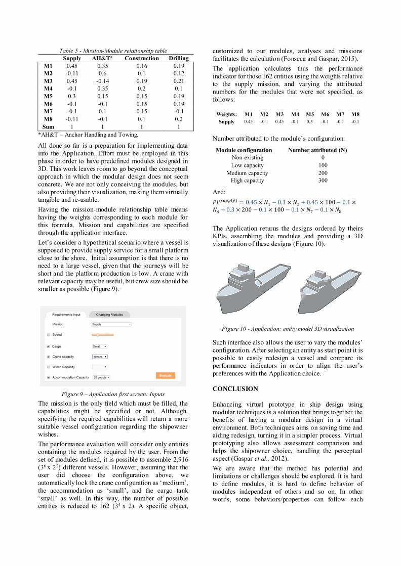
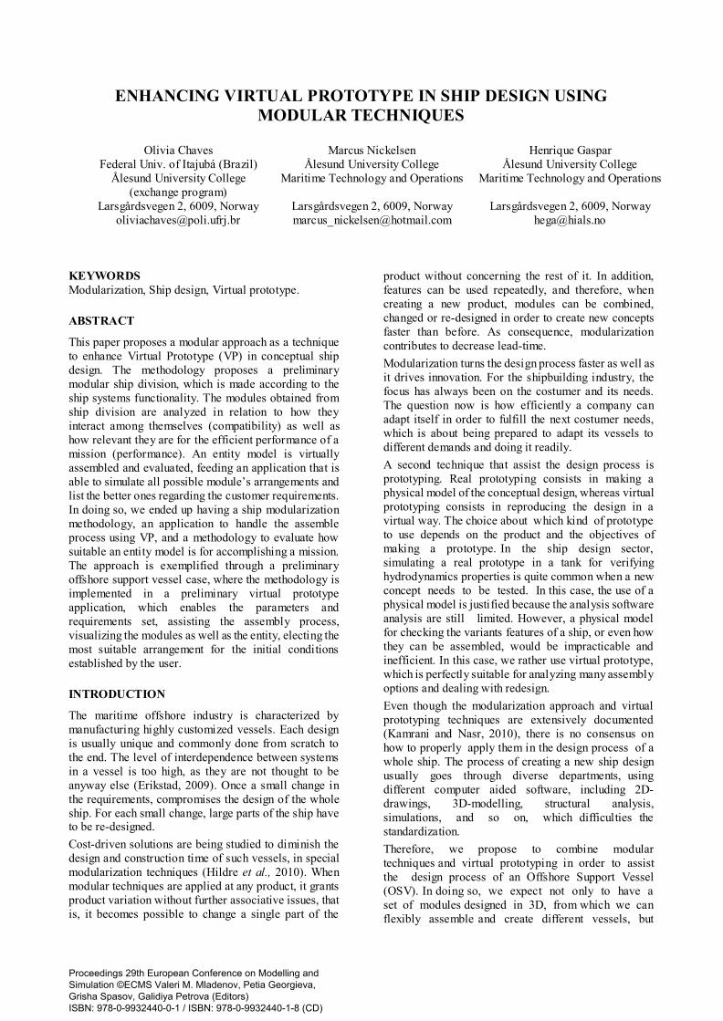
Table 5 - Mission-Module relationship table
Supply AH&T* Construction Drilling
M1 0.45 0.35 0.16 0.19
M2 -0.11 0.6 0.1 0.12
M3 0.45 -0.14 0.19 0.21
M4 -0.1 0.35 0.2 0.1
M5 0.3 0.15 0.15 0.19
M6 -0.1 -0.1 0.15 0.19
M7 -0.1 0.1 0.15 -0.1
M8 -0.11 -0.1 0.1 0.2
Sum 1 1 1 1
*AH&T – Anchor Handling and Towing.
All done so far is a preparation for implementing data
into the Application. Effort must be employed in this
phase in order to have predefined modules designed in
3D. This work leaves room to go beyond the conceptual
approach in which the modular design does not seem
concrete. We are not only conceiving the modules, but
also providing their visualization, making them virtually
tangible and re-usable.
Having the mission-module relationship table means
having the weights corresponding to each module for
this formula. Mission and capabilities are specified
through the application interface.
Let’s consider a hypothetical scenario where a vessel is
supposed to provide supply service for a small platform
close to the shore. Initial assumption is that there is no
need to a large vessel, given that the journeys will be
short and the platform production is low. A crane with
relevant capacity may be useful, but crew size should be
smaller as possible (Figure 9).
Figure 9 – Application first screen: Inputs
The mission is the only field which must be filled, the
capabilities might be specified or not. Although,
specifying the required capabilities will return a more
suitable vessel configuration regarding the shipowner
wishes.
The performance evaluation will consider only entities
containing the modules required by the user. From the
set of modules defined, it is possible to assemble 2,916
(36 x 22) different vessels. However, assuming that the
user did choose the configuration above, we
automatically lock the crane configuration as ‘medium’,
the accommodation as ‘small’, and the cargo tank
‘small’ as well. In this way, the number of possible
entities is reduced to 162 (34 x 2). A specific object,
customized to our modules, analyses and missions
facilitates the calculation (Fonseca and Gaspar, 2015).
The application calculates thus the performance
indicator for those 162 entities using the weights relative
to the supply mission, and varying the attributed
numbers for the modules that were not specified, as
follows:
Weights: M1 M2 M3 M4 M5 M6 M7 M8
Supply 0.45 -0.1 0.45 -0.1 0.3 -0.1 -0.1 -0.1
Number attributed to the module’s configuration:
Module configuration Number attributed (N)
Non-existing 0
Low capacity 100
Medium capacity 200
High capacity 300
And:
𝑃𝐼(𝑠𝑢𝑝𝑝𝑙𝑦) = 0.45 × 𝑁1 − 0.1 × 𝑁2 + 0.45 × 100 − 0.1 ×𝑁4 + 0.3 × 200 − 0.1 × 100 − 0.1 × 𝑁7 − 0.1 × 𝑁8
The Application returns the designs ordered by theirs
KPIs, assembling the modules and providing a 3D
visualization of these designs (Figure 10).
Figure 10 - Application: entity model 3D visualization
Such interface also allows the user to vary the modules’
configuration. After selecting an entity as start point it is
possible to easily redesign a vessel and compare its
performance indicators in order to align the user’s
preferences with the Application choice.
CONCLUSION
Enhancing virtual prototype in ship design using
modular techniques is a solution that brings together the
benefits of having a modular design in a virtual
environment. Both techniques aims on saving time and
aiding redesign, turning it in a simpler process. Virtual
prototyping also allows assessment comparison and
helps the shipowner choice, handling the perceptual
aspect (Gaspar et al., 2012).
We are aware that the method has potential and
limitations or challenges should be explored. It is hard
to define modules, it is hard to define behavior of
modules independent of others and so on. In other
words, some behaviors/properties can follow each

module and others have to be simulated/calculated after
the assembling.
As this is a preliminary case, it is yet unclear if such
methodology is applicable in industrial scale, and more
research on the modules, interfaces and databases is
required. However, based on this preliminary work, we
believe that modular approach to virtual prototyping has
several benefits regarding Ship Design: reduced time in
the ship’s conceptual design phase, less effort in
comparison of ships, quicker and simpler redesign, and
a more visual approach.
Conceptual design is improved, given that acquiring a
fast and precise visual image or animation makes
everything easier on the eye, facilitating new ideas and
solutions in itself, as well as the possibility to navigate
your way around the object, looking for unseen
capabilities.
Efficient modular approach takes this to a new level.
When designing an object or a system with several
different modules, the designer have the possibility to
quickly change a part of the design, generating and
evaluating a new ship. Seamlessly, quick, easy, and
everything is presented to you through a application in
real time, having then the possibility to compare the
designs immediately and to further redesign your object
to satisfy your own requirements.
As for future work, more precise and accurate
calculations are necessary, to find better suited vessels
for the given mission. Furthermore, the evaluation might
not only assess the ship operational performance, but
also give other kinds of responses e.g. hydrodynamics
properties. Efficient parametric methods may aid in this
process (Ebrahimi et al., 2015).
ACKNOWLEDGEMENTS
This research is connected to the Ship Design and
Operations Lab at HIALS, which is partly supported by
the EMIS Project, in cooperation with Ulstein
International AS (Norway) and the Research Council of
Norway.
This work was supported by the Science Without
Borders program. Fellow from CAPES - Process no
88888.067519/2013-00.
REFERENCES
Brekke, Ø. 2012. “Modular Capabilities on Offshore Support
Vessels”. NTNU. Trondheim.
Ebrahimi, A.; P. O. Brett; J. J. Garcia; H. M. Gaspar and Ø.
Kamsvåg. 2015. “Better decision making to improve robustness of OCV designs”. In Proceedings 12th IMDC
(2015). Tokyo.
Erikstad, S.O. 2009. “Modularisation in Shipbuilding and Modular Production”. Working paper (IGLO-MP2020)
NTNU. Trondheim.
Fonseca, Í. A. and H. Gaspar. 2015. “An Object Oriented Approach for Virtual Prototyping in Conceptual Ship
Design”. Proceedings ECMS 2015. Varna.
Gaspar, H. M.; D. H. Rhodes; A. M. Ross and S. O. Erikstad. 2012. "Handling Complexity Aspects in Conceptual Ship
Design: A Systems Engineering Approach". Journal of
Ship Production and Design, November, Volume 28, pp.
145-159. Gaspar, H. M.; P. O. Brett; S. O. Erikstad and A. M. Ross.
2015. “Quantifying value robustness of OSV designs
taking into consideration medium to long term stakeholders’ expectations”. In Proceedings 12th IMDC
(2015). Tokyo.
He, B.; Y. Wang; W. Song and W. Tang. 2014. “Design resource management for virtual prototyping in product
collaborative design.” Proc. IMechE, Part B: Journal of
Engineering Manufacture, 1-17.
Hildre, H. P., Mork, O. J. & Æsøy, V., 2010. The Maritime Innovation Factory.
Kamrani, A. K. and E. A. Nasr. 2010. Engineering Design
Rapid Prototyping. Springer, NY. OSC, 2015. [Online]
Available at: http://www.offsim.no/Training
AUTHOR BIOGRAPHIES
OLIVIA S. CHAVES was born in Maceió, Brazil. In
2010 she started a five-years bachelor course in
mechanical engineering at Federal University of Itajubá
(Brazil), Federal University of Rio de Janeiro (exchange
program) and Ålesund University college (Norway, via
Science without Borders), where she is currently works
for the Ship Design Lab. E-mail:
MARCUS L. NICKELSEN was born in Bærum,
Norway in 1993. In 2012 he started a 3-year bachelor
course in Ship Design/Naval architecture at Aalesund
University College. Intern for Ulstein Group (2014),
where he worked with a modularization project. In
addition to his Bachelor thesis, he is contributing to the
Ship Design Lab at Aalesund University College. His e-
mail address is [email protected]
HENRIQUE M. GASPAR Associate Professor at the
Aalesund University College. PhD degree in Marine
Engineering at the Norwegian University of Science and
Technology, Marine Systems group. Part of the PhD
developed at the Systems Engineering Advancement
Research Initiative (SEAri) at MIT, with complex
system engineering methods applied to the maritime
case. Previous experience as Senior Consultant at Det
Norske Veritas (Norway) and in Oil & Gas in Brazil.
http://www.shiplab.hials.org/.