Embed Size (px)
Citation preview

Instruction Manual: HDN Series Shock Absorbers MM-78760-01
MM-78760-01 Rev D Page 1 of 37 Template FM0403031101 Rev D
Enidine Instruction Manual HDN Series Shock Absorbers MM-78760-01

Instruction Manual: HDN Series Shock Absorbers MM-78760-01
MM-78760-01 Rev D Page 2 of 37 Template FM0403031101 Rev D
Instruction Manual: HDN Series Shock Absorbers MM-78760-01
MM-78760-01 Rev D Page 3 of 37 Template FM0403031101 Rev D
TABLE OF CONTENTS
I. Introduction………………………………………………………………………………………….3 II. Safety Precautions………..….…………………………………………………………………….3
III. General Information……………………………………………………………………………......3 IV. Product Data………………………………………………………………………………………...4 V. Post-Delivery Instructions…………………………………………………………………..........6 VI. Installation…………………………………………………………………………………………...7
VII. Operation…………………………………………………………………………………………...17 VIII. Maintenance………………………………………………………………………………………..21 IX. Field repair………………………………………………………………………………………….33 X. Troubleshooting………..………………………………………………………………………….33 XI. Disposal……………………………………………………………………………………………..35
XII. Contact Information……………………………………………………………………………….35
Instruction Manual: HDN Series Shock Absorbers MM-78760-01
MM-78760-01 Rev D Page 4 of 37 Template FM0403031101 Rev D
I. INTRODUCTION This Instruction Manual is intended to give the user an overview of basic installation, operation, and maintenance of the product.
Caution If Shock Absorber is shipped depressurized with Piston Rod compressed. Do not impact Shock Absorber until Bladder has been pressurized and Piston Rod is fully extended. Read this entire setup guide and follow all setup procedures before impacting Shock Absorber.
Caution If Shock Absorber is to be installed in a freezer, do not impact Shock Absorber until it has fully cooled to freezer temperature, or damage may result.
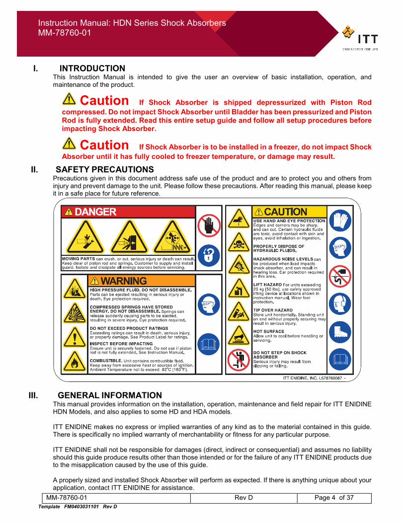
II. SAFETY PRECAUTIONS Precautions given in this document address safe use of the product and are to protect you and others from injury and prevent damage to the unit. Please follow these precautions. After reading this manual, please keep it in a safe place for future reference.
III. GENERAL INFORMATION This manual provides information on the installation, operation, maintenance and field repair for ITT ENIDINE HDN Models, and also applies to some HD and HDA models.
ITT ENIDINE makes no express or implied warranties of any kind as to the material contained in this guide. There is specifically no implied warranty of merchantability or fitness for any particular purpose.
ITT ENIDINE shall not be responsible for damages (direct, indirect or consequential) and assumes no liability should this guide produce results other than those intended or for the failure of any ITT ENIDINE products due to the misapplication caused by the use of this guide.
A properly sized and installed Shock Absorber will perform as expected. If there is anything unique about your application, contact ITT ENIDINE for assistance.
Instruction Manual: HDN Series Shock Absorbers MM-78760-01
MM-78760-01 Rev D Page 5 of 37 Template FM0403031101 Rev D
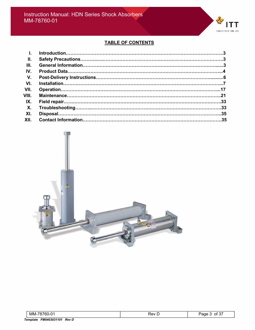
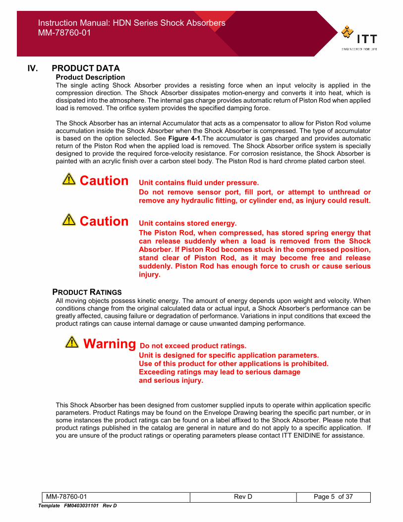
IV. PRODUCT DATA Product Description The single acting Shock Absorber provides a resisting force when an input velocity is applied in the compression direction. The Shock Absorber dissipates motion-energy and converts it into heat, which is dissipated into the atmosphere. The internal gas charge provides automatic return of Piston Rod when applied load is removed. The orifice system provides the specified damping force.
The Shock Absorber has an internal Accumulator that acts as a compensator to allow for Piston Rod volume accumulation inside the Shock Absorber when the Shock Absorber is compressed. The type of accumulator is based on the option selected. See Figure 4-1.The accumulator is gas charged and provides automatic return of the Piston Rod when the applied load is removed. The Shock Absorber orifice system is specially designed to provide the required force-velocity resistance. For corrosion resistance, the Shock Absorber is painted with an acrylic finish over a carbon steel body. The Piston Rod is hard chrome plated carbon steel.
Caution Unit contains fluid under pressure. Do not remove sensor port, fill port, or attempt to unthread or remove any hydraulic fitting, or cylinder end, as injury could result.
Caution Unit contains stored energy. The Piston Rod, when compressed, has stored spring energy that can release suddenly when a load is removed from the Shock Absorber. If Piston Rod becomes stuck in the compressed position, stand clear of Piston Rod, as it may become free and release suddenly. Piston Rod has enough force to crush or cause serious injury.
PRODUCT RATINGS All moving objects possess kinetic energy. The amount of energy depends upon weight and velocity. When conditions change from the original calculated data or actual input, a Shock Absorber’s performance can be greatly affected, causing failure or degradation of performance. Variations in input conditions that exceed the product ratings can cause internal damage or cause unwanted damping performance.
Warning Do not exceed product ratings. Unit is designed for specific application parameters.
Use of this product for other applications is prohibited. Exceeding ratings may lead to serious damage and serious injury.
This Shock Absorber has been designed from customer supplied inputs to operate within application specific parameters. Product Ratings may be found on the Envelope Drawing bearing the specific part number, or in some instances the product ratings can be found on a label affixed to the Shock Absorber. Please note that product ratings published in the catalog are general in nature and do not apply to a specific application. If you are unsure of the product ratings or operating parameters please contact ITT ENIDINE for assistance.
Instruction Manual: HDN Series Shock Absorbers MM-78760-01
MM-78760-01 Rev D Page 6 of 37 Template FM0403031101 Rev D
IV. PRODUCT DATA (CONT’D)
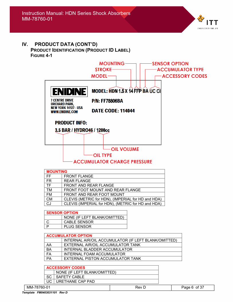
PRODUCT IDENTIFICATION (PRODUCT ID LABEL) FIGURE 4-1
MOUNTING FF FRONT FLANGE FR REAR FLANGE TF FRONT AND REAR FLANGE TM FRONT FOOT MOUNT AND REAR FLANGE FM FRONT AND REAR FOOT MOUNT CM CLEVIS (METRIC for HDN), (IMPERIAL for HD and HDA) CJ CLEVIS (IMPERIAL for HDN), (METRIC for HD and HDA)
SENSOR OPTION NONE (IF LEFT BLANK/OMITTED) C CABLE SENSOR P PLUG SENSOR
ACCUMULATOR OPTION INTERNAL AIR/OIL ACCUMULATOR (IF LEFT BLANK/OMITTED) AA EXTERNAL AIR/OIL ACCUMULATOR TANK BA INTERNAL BLADDER ACCUMULATOR FA INTERNAL FOAM ACCUMULATOR PA EXTERNAL PISTON ACCUMULATOR TANK
ACCESSORY CODES NONE (IF LEFT BLANK/OMITTED) SC SAFETY CABLE UC URETHANE CAP PAD
Instruction Manual: HDN Series Shock Absorbers MM-78760-01
MM-78760-01 Rev D Page 7 of 37 Template FM0403031101 Rev D
CI CAST IRON PISTON RING SEAL (FACTORY SELECTED) IV. PRODUCT DATA (CONT’D)
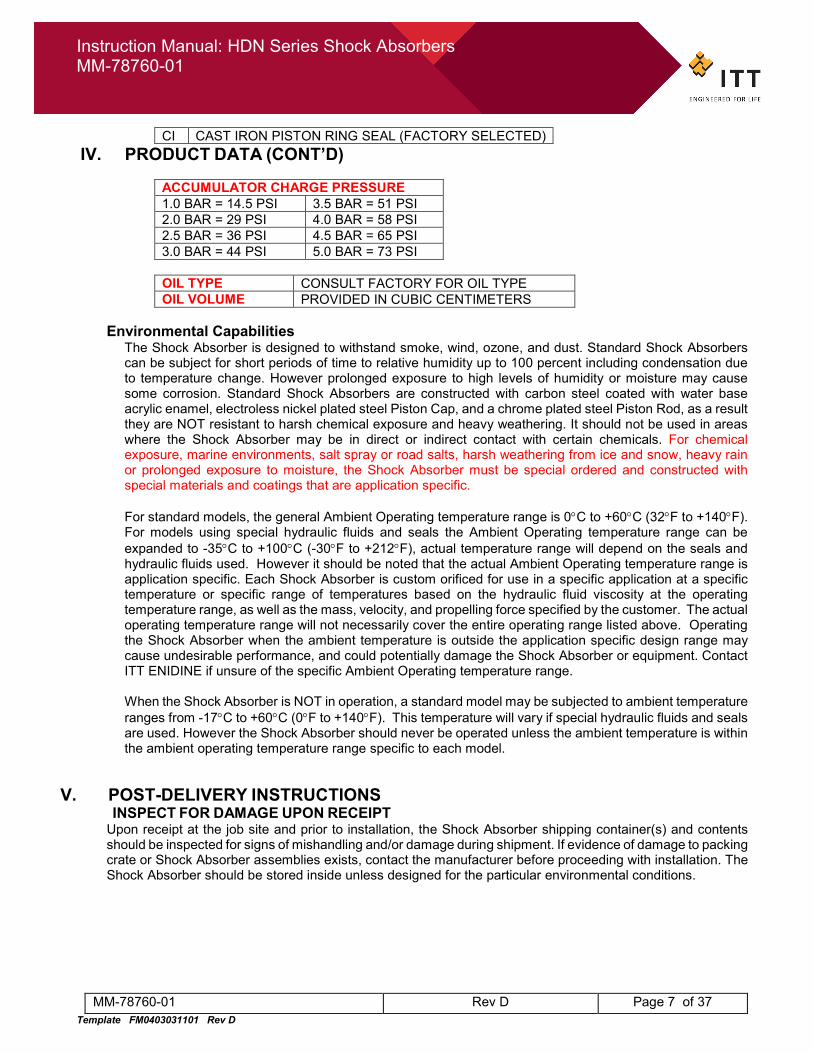
ACCUMULATOR CHARGE PRESSURE 1.0 BAR = 14.5 PSI 3.5 BAR = 51 PSI 2.0 BAR = 29 PSI 4.0 BAR = 58 PSI 2.5 BAR = 36 PSI 4.5 BAR = 65 PSI 3.0 BAR = 44 PSI 5.0 BAR = 73 PSI
OIL TYPE CONSULT FACTORY FOR OIL TYPE OIL VOLUME PROVIDED IN CUBIC CENTIMETERS
Environmental Capabilities
The Shock Absorber is designed to withstand smoke, wind, ozone, and dust. Standard Shock Absorbers can be subject for short periods of time to relative humidity up to 100 percent including condensation due to temperature change. However prolonged exposure to high levels of humidity or moisture may cause some corrosion. Standard Shock Absorbers are constructed with carbon steel coated with water base acrylic enamel, electroless nickel plated steel Piston Cap, and a chrome plated steel Piston Rod, as a result they are NOT resistant to harsh chemical exposure and heavy weathering. It should not be used in areas where the Shock Absorber may be in direct or indirect contact with certain chemicals. For chemical exposure, marine environments, salt spray or road salts, harsh weathering from ice and snow, heavy rain or prolonged exposure to moisture, the Shock Absorber must be special ordered and constructed with special materials and coatings that are application specific. For standard models, the general Ambient Operating temperature range is 0°C to +60°C (32°F to +140°F). For models using special hydraulic fluids and seals the Ambient Operating temperature range can be expanded to -35°C to +100°C (-30°F to +212°F), actual temperature range will depend on the seals and hydraulic fluids used. However it should be noted that the actual Ambient Operating temperature range is application specific. Each Shock Absorber is custom orificed for use in a specific application at a specific temperature or specific range of temperatures based on the hydraulic fluid viscosity at the operating temperature range, as well as the mass, velocity, and propelling force specified by the customer. The actual operating temperature range will not necessarily cover the entire operating range listed above. Operating the Shock Absorber when the ambient temperature is outside the application specific design range may cause undesirable performance, and could potentially damage the Shock Absorber or equipment. Contact ITT ENIDINE if unsure of the specific Ambient Operating temperature range.
When the Shock Absorber is NOT in operation, a standard model may be subjected to ambient temperature ranges from -17°C to +60°C (0°F to +140°F). This temperature will vary if special hydraulic fluids and seals are used. However the Shock Absorber should never be operated unless the ambient temperature is within the ambient operating temperature range specific to each model.
V. POST-DELIVERY INSTRUCTIONS
INSPECT FOR DAMAGE UPON RECEIPT Upon receipt at the job site and prior to installation, the Shock Absorber shipping container(s) and contents should be inspected for signs of mishandling and/or damage during shipment. If evidence of damage to packing crate or Shock Absorber assemblies exists, contact the manufacturer before proceeding with installation. The Shock Absorber should be stored inside unless designed for the particular environmental conditions.
Instruction Manual: HDN Series Shock Absorbers MM-78760-01
MM-78760-01 Rev D Page 8 of 37 Template FM0403031101 Rev D
VI. INSTALLATION
Caution PRE-INSTALLATION PROCEDURE FOR FREEZER INSTALLATIONS If this product is to be used in a freezer, special handling and installations procedures need to be followed to prevent thermal stresses experienced during the transition from room temperature (40°F to 104°F) to freezer temperature from causing a product failure. Please use the following pre-installation procedure for freezer installations. If this product is not used in a freezer, skip this procedure.
FREEZER PRE-INSTALLATION PROCEDURE (FOR FREEZER INSTALLATIONS ONLY): 1. Move crate containing the Shock Absorber into the freezer where Shock Absorber will
be installed, but do not open crate or remove Shock Absorber from crate. Shock Absorber to remain bolted into crate. Allow to cool at least 4 hours to freezer temperature before opening crate. This will help to slow the cooling process, and minimize thermal stress.
2. After Shock Absorber has cooled to freezer temperature, crate may be opened, and Shock Absorber may be installed. Continue to follow the rest of the standard installation procedures below.
3. Note: if product is being installed in a freezer, where the freezer is currently at room
temperature, and the freezer will be cooled to freezer temperature after the Shock Absorber has been installed, proceed to follow the standard installation procedure below, and ensure Shock Absorber is securely bolted into place before cooling the freezer.
4. Do not impact Shock Absorber, until it has fully cooled to freezer temperature.
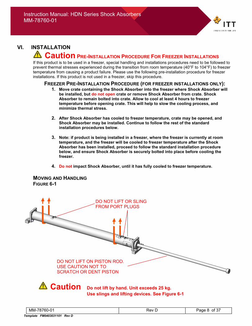
MOVING AND HANDLING FIGURE 6-1
Caution Do not lift by hand. Unit exceeds 25 kg. Use slings and lifting devices. See Figure 6-1
DO NOT LIFT ON PISTON ROD. USE CAUTION NOT TO SCRATCH OR DENT PISTON
DO NOT LIFT OR SLING FROM PORT PLUGS
Instruction Manual: HDN Series Shock Absorbers MM-78760-01
MM-78760-01 Rev D Page 9 of 37 Template FM0403031101 Rev D
VI. INSTALLATION (CONT’D)
Warning Tipping Hazard. Store unit horizontally on flat surface. Do not store or stand Shock Absorber vertically on cylinder end without properly securing or supporting the Shock Absorber, otherwise a tipping hazard could result.
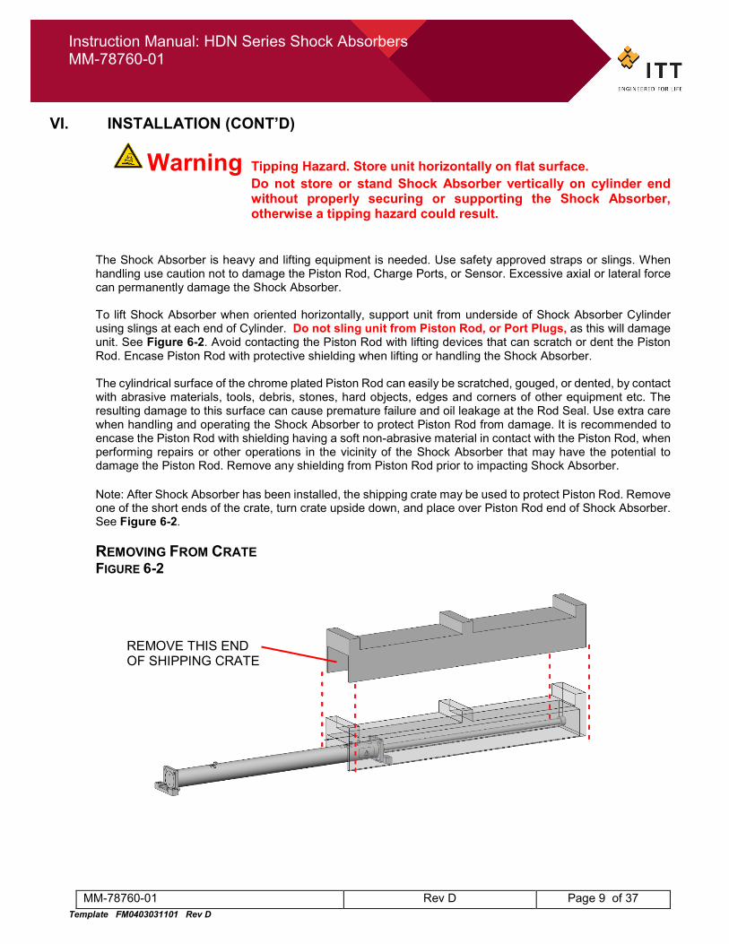
The Shock Absorber is heavy and lifting equipment is needed. Use safety approved straps or slings. When handling use caution not to damage the Piston Rod, Charge Ports, or Sensor. Excessive axial or lateral force can permanently damage the Shock Absorber. To lift Shock Absorber when oriented horizontally, support unit from underside of Shock Absorber Cylinder using slings at each end of Cylinder. Do not sling unit from Piston Rod, or Port Plugs, as this will damage unit. See Figure 6-2. Avoid contacting the Piston Rod with lifting devices that can scratch or dent the Piston Rod. Encase Piston Rod with protective shielding when lifting or handling the Shock Absorber. The cylindrical surface of the chrome plated Piston Rod can easily be scratched, gouged, or dented, by contact with abrasive materials, tools, debris, stones, hard objects, edges and corners of other equipment etc. The resulting damage to this surface can cause premature failure and oil leakage at the Rod Seal. Use extra care when handling and operating the Shock Absorber to protect Piston Rod from damage. It is recommended to encase the Piston Rod with shielding having a soft non-abrasive material in contact with the Piston Rod, when performing repairs or other operations in the vicinity of the Shock Absorber that may have the potential to damage the Piston Rod. Remove any shielding from Piston Rod prior to impacting Shock Absorber. Note: After Shock Absorber has been installed, the shipping crate may be used to protect Piston Rod. Remove one of the short ends of the crate, turn crate upside down, and place over Piston Rod end of Shock Absorber. See Figure 6-2. REMOVING FROM CRATE FIGURE 6-2
REMOVE THIS END OF SHIPPING CRATE
Instruction Manual: HDN Series Shock Absorbers MM-78760-01
MM-78760-01 Rev D Page 10 of 37 Template FM0403031101 Rev D
VI. INSTALLATION (CONT’D)
MOUNTING Although actual installation is the responsibility of the Customer, ITT ENIDINE recommends the following basic installation guide lines:
• The Shock Absorber should be mounted to a frame or structure capable of supporting the maximum dynamic load equal to the maximum shock force of the Shock Absorber plus safety factor, and any fatigue lifecycle considerations.
• Align the Shock Absorber mount bolt holes to structure. Secure the Shock Absorber using all mounting
holes provided using bolts conforming to DIN 912 class 12.9, or ASTM A574. Securely torque bolts to recommended torque. See Table 6-1 for recommended bolts and tightening torque. If bolts of a different material or property grade are utilized it will be the customers responsibility to ensure they meet the proper load ratings, refer to the bolt manufactures seating torque recommendations.
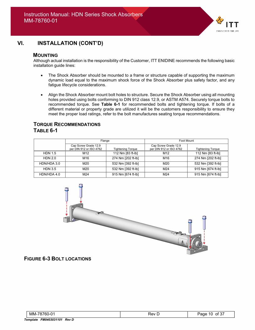
TORQUE RECOMMENDATIONS TABLE 6-1
Flange Foot Mount
Cap Screw Grade 12.9 per DIN 912 or ISO 4762 Tightening Torque
Cap Screw Grade 12.9 per DIN 912 or ISO 4762 Tightening Torque
HDN 1.5 M12 112 Nm [83 ft-lb] M12 112 Nm [83 ft-lb] HDN 2.0 M16 274 Nm [202 ft-lb] M16 274 Nm [202 ft-lb]
HDN/HDA 3.0 M20 532 Nm [392 ft-lb] M20 532 Nm [392 ft-lb] HDN 3.5 M20 532 Nm [392 ft-lb] M24 915 Nm [674 ft-lb]
HDN/HDA 4.0 M24 915 Nm [674 ft-lb] M24 915 Nm [674 ft-lb]
FIGURE 6-3 BOLT LOCATIONS
Instruction Manual: HDN Series Shock Absorbers MM-78760-01
MM-78760-01 Rev D Page 11 of 37 Template FM0403031101 Rev D
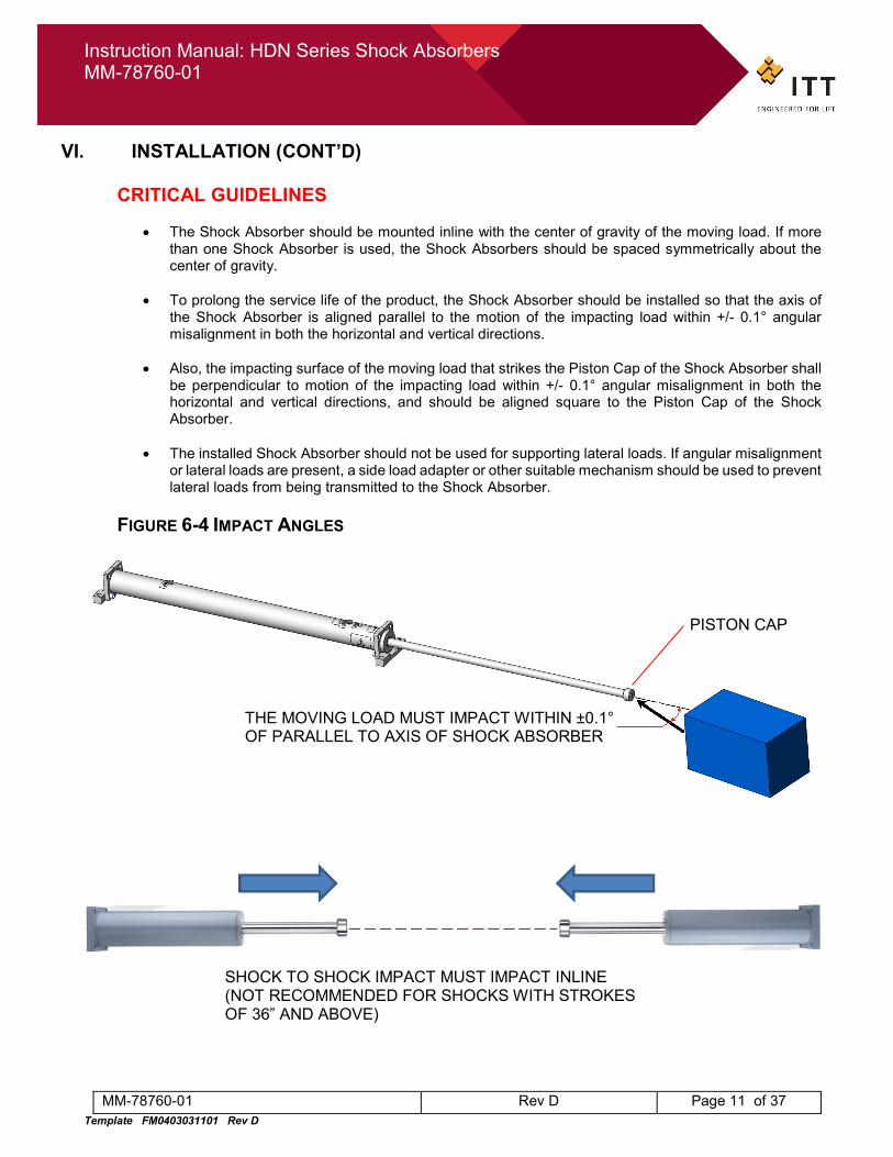
VI. INSTALLATION (CONT’D) CRITICAL GUIDELINES
• The Shock Absorber should be mounted inline with the center of gravity of the moving load. If more
than one Shock Absorber is used, the Shock Absorbers should be spaced symmetrically about the center of gravity.
• To prolong the service life of the product, the Shock Absorber should be installed so that the axis of
the Shock Absorber is aligned parallel to the motion of the impacting load within +/- 0.1° angular misalignment in both the horizontal and vertical directions.
• Also, the impacting surface of the moving load that strikes the Piston Cap of the Shock Absorber shall
be perpendicular to motion of the impacting load within +/- 0.1° angular misalignment in both the horizontal and vertical directions, and should be aligned square to the Piston Cap of the Shock Absorber.
• The installed Shock Absorber should not be used for supporting lateral loads. If angular misalignment
or lateral loads are present, a side load adapter or other suitable mechanism should be used to prevent lateral loads from being transmitted to the Shock Absorber.
FIGURE 6-4 IMPACT ANGLES
THE MOVING LOAD MUST IMPACT WITHIN ±0.1° OF PARALLEL TO AXIS OF SHOCK ABSORBER
PISTON CAP
SHOCK TO SHOCK IMPACT MUST IMPACT INLINE (NOT RECOMMENDED FOR SHOCKS WITH STROKES OF 36” AND ABOVE)
Instruction Manual: HDN Series Shock Absorbers MM-78760-01
MM-78760-01 Rev D Page 12 of 37 Template FM0403031101 Rev D
VI. INSTALLATION (CONT’D)
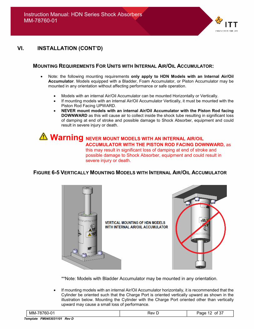
MOUNTING REQUIREMENTS FOR UNITS WITH INTERNAL AIR/OIL ACCUMULATOR:
• Note: the following mounting requirements only apply to HDN Models with an Internal Air/Oil Accumulator. Models equipped with a Bladder, Foam Accumulator, or Piston Accumulator may be mounted in any orientation without affecting performance or safe operation.
• Models with an internal Air/Oil Accumulator can be mounted Horizontally or Vertically. • If mounting models with an internal Air/Oil Accumulator Vertically, it must be mounted with the
Piston Rod Facing UPWARD. • NEVER mount models with an internal Air/Oil Accumulator with the Piston Rod facing
DOWNWARD as this will cause air to collect inside the shock tube resulting in significant loss of damping at end of stroke and possible damage to Shock Absorber, equipment and could result in severe injury or death.
Warning NEVER MOUNT MODELS WITH AN INTERNAL AIR/OIL ACCUMULATOR WITH THE PISTON ROD FACING DOWNWARD, as this may result in significant loss of damping at end of stroke and possible damage to Shock Absorber, equipment and could result in severe injury or death.
FIGURE 6-5 VERTICALLY MOUNTING MODELS WITH INTERNAL AIR/OIL ACCUMULATOR
**Note: Models with Bladder Accumulator may be mounted in any orientation.
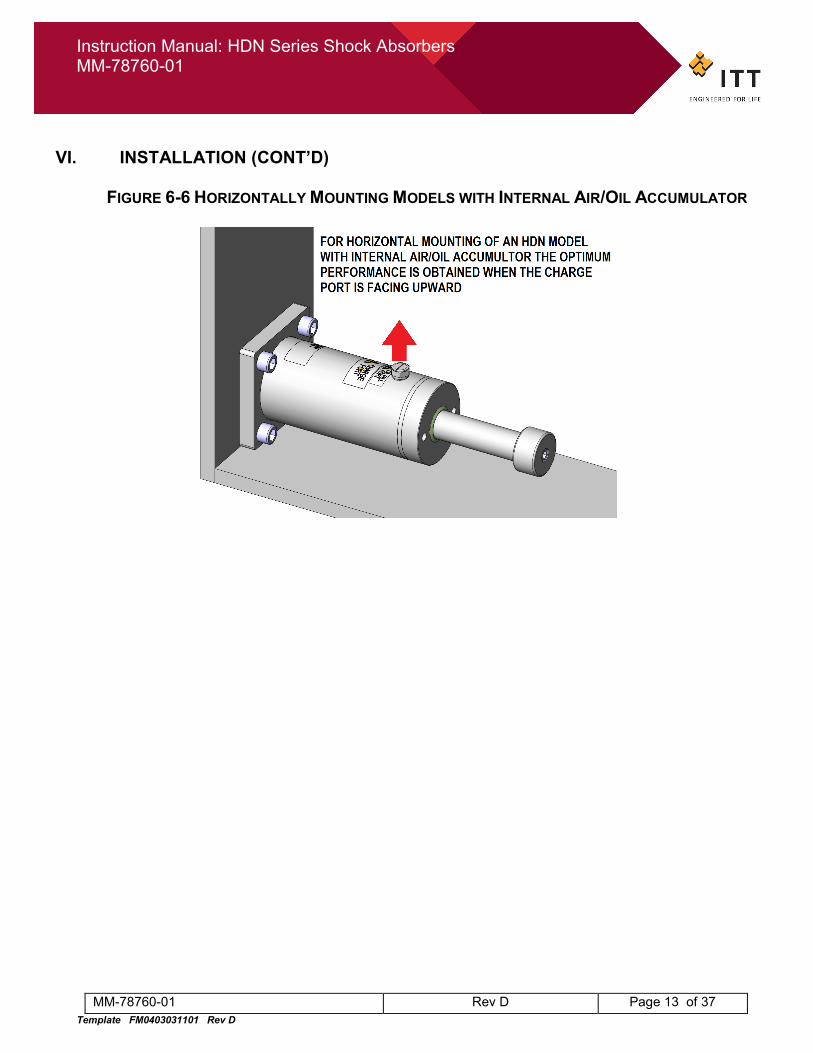
• If mounting models with an internal Air/Oil Accumulator horizontally, it is recommended that the Cylinder be oriented such that the Charge Port is oriented vertically upward as shown in the illustration below. Mounting the Cylinder with the Charge Port oriented other than vertically upward may cause a small loss of performance.
Instruction Manual: HDN Series Shock Absorbers MM-78760-01
MM-78760-01 Rev D Page 13 of 37 Template FM0403031101 Rev D
VI. INSTALLATION (CONT’D)
FIGURE 6-6 HORIZONTALLY MOUNTING MODELS WITH INTERNAL AIR/OIL ACCUMULATOR
Instruction Manual: HDN Series Shock Absorbers MM-78760-01
MM-78760-01 Rev D Page 14 of 37 Template FM0403031101 Rev D
VI. INSTALLATION (CONT’D)
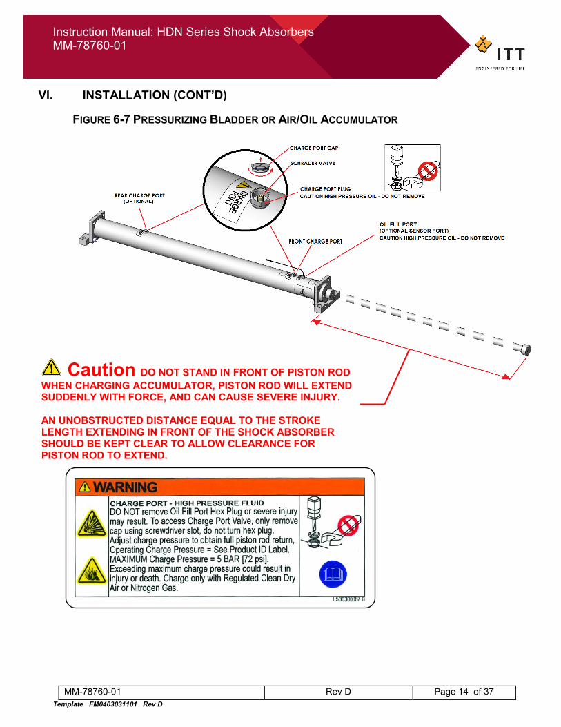
FIGURE 6-7 PRESSURIZING BLADDER OR AIR/OIL ACCUMULATOR
Caution DO NOT STAND IN FRONT OF PISTON ROD WHEN CHARGING ACCUMULATOR, PISTON ROD WILL EXTEND SUDDENLY WITH FORCE, AND CAN CAUSE SEVERE INJURY. AN UNOBSTRUCTED DISTANCE EQUAL TO THE STROKE LENGTH EXTENDING IN FRONT OF THE SHOCK ABSORBER SHOULD BE KEPT CLEAR TO ALLOW CLEARANCE FOR PISTON ROD TO EXTEND.
Instruction Manual: HDN Series Shock Absorbers MM-78760-01
MM-78760-01 Rev D Page 15 of 37 Template FM0403031101 Rev D
VI. INSTALLATION (CONT’D)
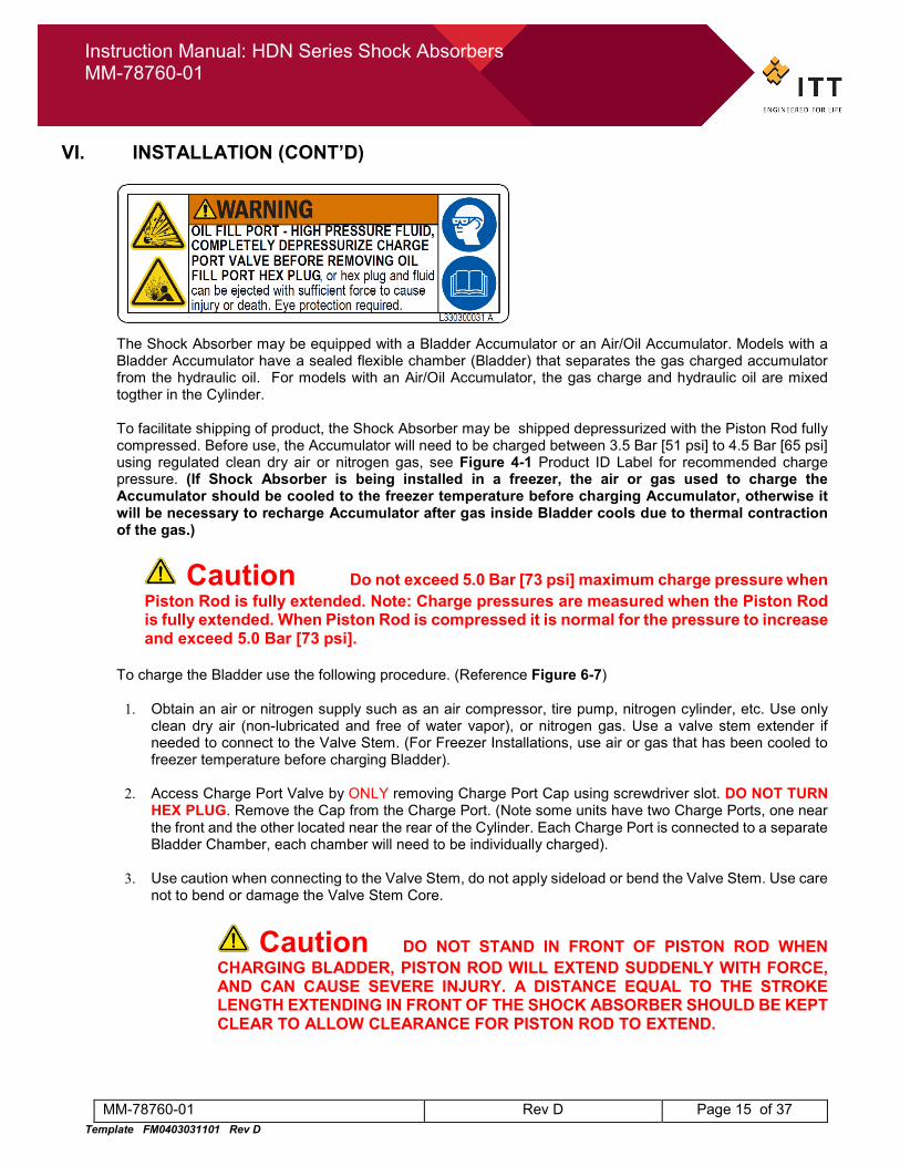
The Shock Absorber may be equipped with a Bladder Accumulator or an Air/Oil Accumulator. Models with a Bladder Accumulator have a sealed flexible chamber (Bladder) that separates the gas charged accumulator from the hydraulic oil. For models with an Air/Oil Accumulator, the gas charge and hydraulic oil are mixed togther in the Cylinder. To facilitate shipping of product, the Shock Absorber may be shipped depressurized with the Piston Rod fully compressed. Before use, the Accumulator will need to be charged between 3.5 Bar [51 psi] to 4.5 Bar [65 psi] using regulated clean dry air or nitrogen gas, see Figure 4-1 Product ID Label for recommended charge pressure. (If Shock Absorber is being installed in a freezer, the air or gas used to charge the Accumulator should be cooled to the freezer temperature before charging Accumulator, otherwise it will be necessary to recharge Accumulator after gas inside Bladder cools due to thermal contraction of the gas.)
Caution Do not exceed 5.0 Bar [73 psi] maximum charge pressure when Piston Rod is fully extended. Note: Charge pressures are measured when the Piston Rod is fully extended. When Piston Rod is compressed it is normal for the pressure to increase and exceed 5.0 Bar [73 psi].
To charge the Bladder use the following procedure. (Reference Figure 6-7)
1. Obtain an air or nitrogen supply such as an air compressor, tire pump, nitrogen cylinder, etc. Use only clean dry air (non-lubricated and free of water vapor), or nitrogen gas. Use a valve stem extender if needed to connect to the Valve Stem. (For Freezer Installations, use air or gas that has been cooled to freezer temperature before charging Bladder).
2. Access Charge Port Valve by ONLY removing Charge Port Cap using screwdriver slot. DO NOT TURN
HEX PLUG. Remove the Cap from the Charge Port. (Note some units have two Charge Ports, one near the front and the other located near the rear of the Cylinder. Each Charge Port is connected to a separate Bladder Chamber, each chamber will need to be individually charged).
3. Use caution when connecting to the Valve Stem, do not apply sideload or bend the Valve Stem. Use care
not to bend or damage the Valve Stem Core.
Caution DO NOT STAND IN FRONT OF PISTON ROD WHEN CHARGING BLADDER, PISTON ROD WILL EXTEND SUDDENLY WITH FORCE, AND CAN CAUSE SEVERE INJURY. A DISTANCE EQUAL TO THE STROKE LENGTH EXTENDING IN FRONT OF THE SHOCK ABSORBER SHOULD BE KEPT CLEAR TO ALLOW CLEARANCE FOR PISTON ROD TO EXTEND.
Instruction Manual: HDN Series Shock Absorbers MM-78760-01
MM-78760-01 Rev D Page 16 of 37 Template FM0403031101 Rev D
VI. INSTALLATION (CONT’D)
4. For units having only one Charge Port:
a. using the Schrader Valve inside the port, apply air to the Valve Stem (see Figure 6-7) to inflate the Bladder to 3.5 Bar [51 psi] to 4.5 Bar [65 psi], see Product ID Label for recommend charge pressure. As air is applied, the Piston Rod will be begin to extend.
b. Continue to add air until the Piston Rod is fully extended, and the pressure remains steady at the recommened charge pressure. When the Piston Rod reaches its fully extended position, an audible impact should be heard as it hits an internal hard positive stop.
c. Skip to step 6.
5. For units having two Charge Ports:
a. Starting at the Rear Charge Port (Furthest away from Piston Rod) and using the Schrader Valve inside the port, apply air to the Valve Stem to inflate the Rear Bladder to 3.0 Bar [44 psi]. As air is applied, the Piston Rod will be begin to extend.
b. Now move to the Front Charge Port (Nearest to Piston Rod) and using the Schrader Valve inside the port, apply air to the Valve Stem (see Figure 6-7) to inflate the Front Bladder to 4.5 Bar [65 psi] or the recommended charge pressure per the Product ID Label. Continue to add air until the Piston Rod fully extends, and the pressure remains steady at the recommened charge pressure. When the Piston Rod reaches its fully extended position, an audible impact should be heard as it hits an internal hard positive stop.
c. Move to the Rear Charge Port and add air to the Schrader Valve until pressure reaches
4.5 Bar [65 psi] or the recommended charge pressure per Figure 4-1 Product ID Label. The pressure is measured when the Piston Rod is fully extended.
d. Move to the Front Charge Port and verify the pressure still measures the recommended
charge pressure per the Product ID Label, add or remove air as required. The pressure is measured when the Piston Rod is fully extended.
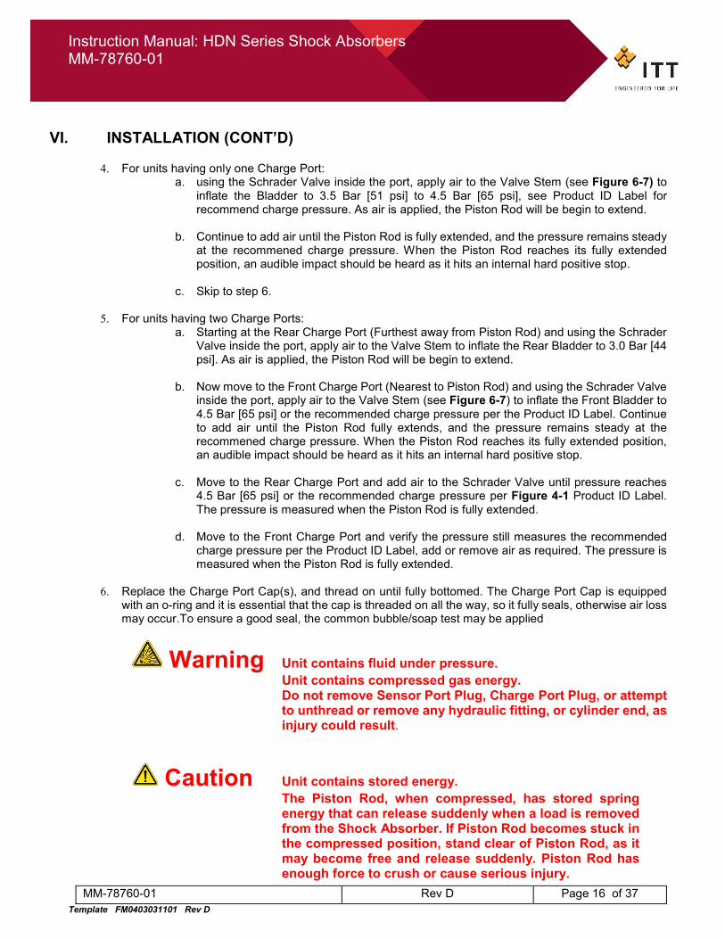
6. Replace the Charge Port Cap(s), and thread on until fully bottomed. The Charge Port Cap is equipped
with an o-ring and it is essential that the cap is threaded on all the way, so it fully seals, otherwise air loss may occur.To ensure a good seal, the common bubble/soap test may be applied
Warning Unit contains fluid under pressure. Unit contains compressed gas energy.
Do not remove Sensor Port Plug, Charge Port Plug, or attempt to unthread or remove any hydraulic fitting, or cylinder end, as injury could result.
Caution Unit contains stored energy. The Piston Rod, when compressed, has stored spring energy that can release suddenly when a load is removed from the Shock Absorber. If Piston Rod becomes stuck in the compressed position, stand clear of Piston Rod, as it may become free and release suddenly. Piston Rod has enough force to crush or cause serious injury.
Instruction Manual: HDN Series Shock Absorbers MM-78760-01
MM-78760-01 Rev D Page 17 of 37 Template FM0403031101 Rev D
VI. INSTALLATION (CONT’D)
7. If removing Shock Absorber from freezer, depressurize Charge Port to 3.5 Bar [51 psi] (If Shock Absorber
is equiped with two Charge Ports, ensure both Charge Ports are depressurized to 3.5 Bar [51 psi]) before removing Shock Absorber from freezer. After removing from freezer allow Shock Absorber to fully warm up to ambient temperature (allow at least 4 hours), then recharge Bladder to recommended charge pressure before operating. Do not impact Shock Absorber until is has fully warmed up to ambient temperature.
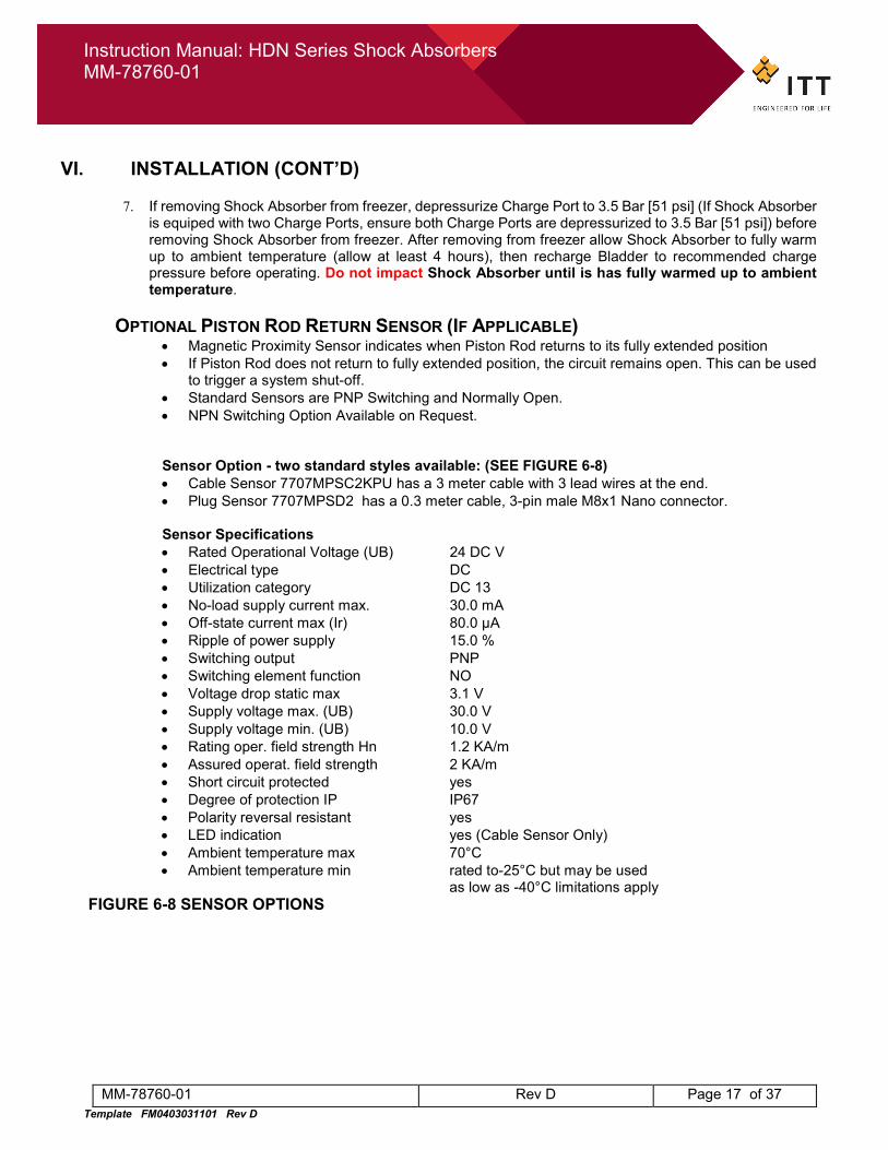
OPTIONAL PISTON ROD RETURN SENSOR (IF APPLICABLE)
• Magnetic Proximity Sensor indicates when Piston Rod returns to its fully extended position • If Piston Rod does not return to fully extended position, the circuit remains open. This can be used
to trigger a system shut-off. • Standard Sensors are PNP Switching and Normally Open. • NPN Switching Option Available on Request.
Sensor Option - two standard styles available: (SEE FIGURE 6-8) • Cable Sensor 7707MPSC2KPU has a 3 meter cable with 3 lead wires at the end. • Plug Sensor 7707MPSD2 has a 0.3 meter cable, 3-pin male M8x1 Nano connector. Sensor Specifications • Rated Operational Voltage (UB) 24 DC V • Electrical type DC • Utilization category DC 13 • No-load supply current max. 30.0 mA • Off-state current max (Ir) 80.0 µA • Ripple of power supply 15.0 % • Switching output PNP • Switching element function NO • Voltage drop static max 3.1 V • Supply voltage max. (UB) 30.0 V • Supply voltage min. (UB) 10.0 V • Rating oper. field strength Hn 1.2 KA/m • Assured operat. field strength 2 KA/m • Short circuit protected yes • Degree of protection IP IP67 • Polarity reversal resistant yes • LED indication yes (Cable Sensor Only) • Ambient temperature max 70°C • Ambient temperature min rated to-25°C but may be used as low as -40°C limitations apply
FIGURE 6-8 SENSOR OPTIONS
Instruction Manual: HDN Series Shock Absorbers MM-78760-01
MM-78760-01 Rev D Page 18 of 37 Template FM0403031101 Rev D
VI. INSTALLATION (CONT’D)
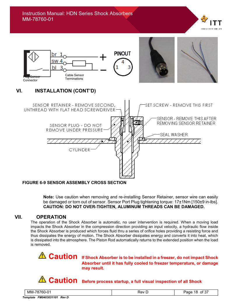
FIGURE 6-9 SENSOR ASSEMBLY CROSS SECTION
Note: Use caution when removing and re-installing Sensor Retainer, sensor wire can easily be damaged or torn out of sensor. Sensor Port Plug tightening torque: 17±1Nm [150±9 in-lbs]. CAUTION: DO NOT OVER-TIGHTEN, ALUMINUM THREADS CAN BE DAMAGED.
VII. OPERATION
The operation of the Shock Absorber is automatic, no user intervention is required. When a moving load impacts the Shock Absorber in the compression direction providing an input velocity, a hydraulic flow inside the Shock Absorber is produced which forces fluid thru a series of orifice holes providing a resisting force and thus dissipates the energy of motion. The Shock Absorber dissipates energy and converts it into heat, which is dissipated into the atmosphere. The Piston Rod automatically returns to the extended position when the load is removed.
Caution If Shock Absorber is to be installed in a freezer, do not impact Shock Absorber until it has fully cooled to freezer temperature, or damage may result.
Caution Before process startup, a full visual inspection of all Shock
Plug Sensor Connector
Cable Sensor Terminations
Instruction Manual: HDN Series Shock Absorbers MM-78760-01
MM-78760-01 Rev D Page 19 of 37 Template FM0403031101 Rev D
Absorbers and installation conditions is recommended. Do not use product if Piston Rod is not fully extended.
VII. OPERATION (CONT’D)
Warning Do not exceed product ratings. Unit is designed for specific application parameters.
Use of this product for other applications is prohibited. Exceeding ratings may lead to serious damage and serious injury.
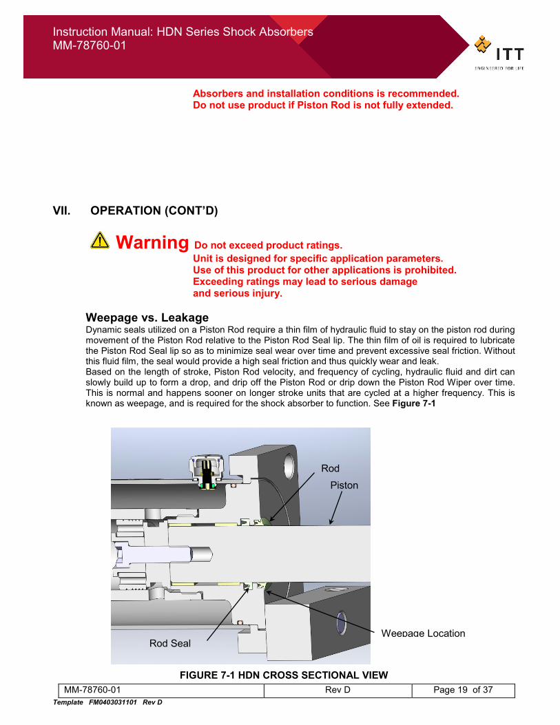
Weepage vs. Leakage
Dynamic seals utilized on a Piston Rod require a thin film of hydraulic fluid to stay on the piston rod during movement of the Piston Rod relative to the Piston Rod Seal lip. The thin film of oil is required to lubricate the Piston Rod Seal lip so as to minimize seal wear over time and prevent excessive seal friction. Without this fluid film, the seal would provide a high seal friction and thus quickly wear and leak. Based on the length of stroke, Piston Rod velocity, and frequency of cycling, hydraulic fluid and dirt can slowly build up to form a drop, and drip off the Piston Rod or drip down the Piston Rod Wiper over time. This is normal and happens sooner on longer stroke units that are cycled at a higher frequency. This is known as weepage, and is required for the shock absorber to function. See Figure 7-1
FIGURE 7-1 HDN CROSS SECTIONAL VIEW
Rod Piston
Rod Seal Weepage Location
Instruction Manual: HDN Series Shock Absorbers MM-78760-01
MM-78760-01 Rev D Page 20 of 37 Template FM0403031101 Rev D
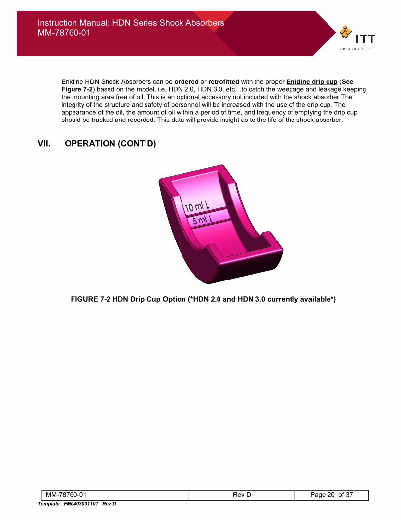
Enidine HDN Shock Absorbers can be ordered or retrofitted with the proper Enidine drip cup (See Figure 7-2) based on the model, i.e, HDN 2.0, HDN 3.0, etc…to catch the weepage and leakage keeping the mounting area free of oil. This is an optional accessory not included with the shock absorber.The integrity of the structure and safety of personnel will be increased with the use of the drip cup. The appearance of the oil, the amount of oil within a period of time, and frequency of emptying the drip cup should be tracked and recorded. This data will provide insight as to the life of the shock absorber.
VII. OPERATION (CONT’D)
FIGURE 7-2 HDN Drip Cup Option (*HDN 2.0 and HDN 3.0 currently available*)
Instruction Manual: HDN Series Shock Absorbers MM-78760-01
MM-78760-01 Rev D Page 21 of 37 Template FM0403031101 Rev D
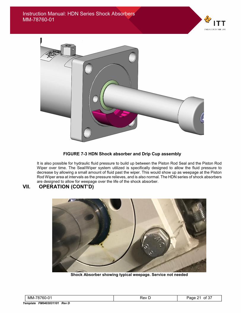
FIGURE 7-3 HDN Shock absorber and Drip Cup assembly
It is also possible for hydraulic fluid pressure to build up between the Piston Rod Seal and the Piston Rod Wiper over time. The Seal/Wiper system utilized is specifically designed to allow the fluid pressure to decrease by allowing a small amount of fluid past the wiper. This would show up as weepage at the Piston Rod Wiper area at intervals as the pressure relieves, and is also normal. The HDN series of shock absorbers are designed to allow for weepage over the life of the shock absorber.
VII. OPERATION (CONT’D)
Shock Absorber showing typical weepage. Service not needed
Instruction Manual: HDN Series Shock Absorbers MM-78760-01
MM-78760-01 Rev D Page 22 of 37 Template FM0403031101 Rev D
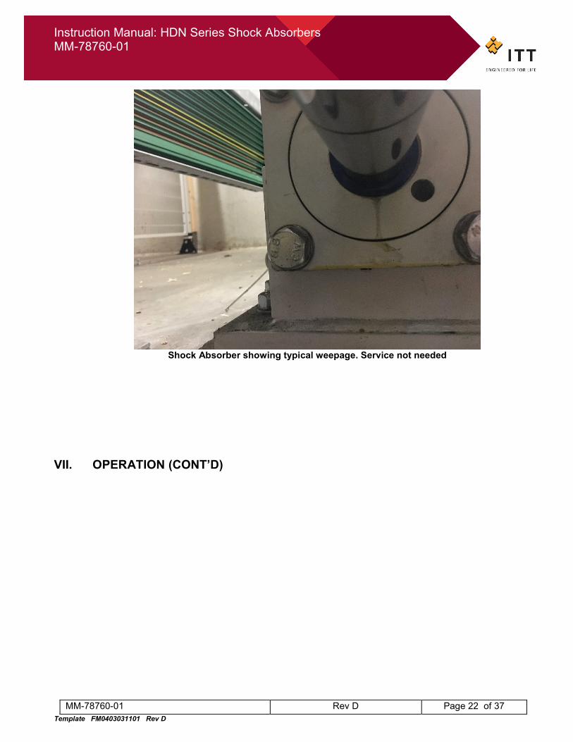
Shock Absorber showing typical weepage. Service not needed
VII. OPERATION (CONT’D)
Instruction Manual: HDN Series Shock Absorbers MM-78760-01
MM-78760-01 Rev D Page 23 of 37 Template FM0403031101 Rev D
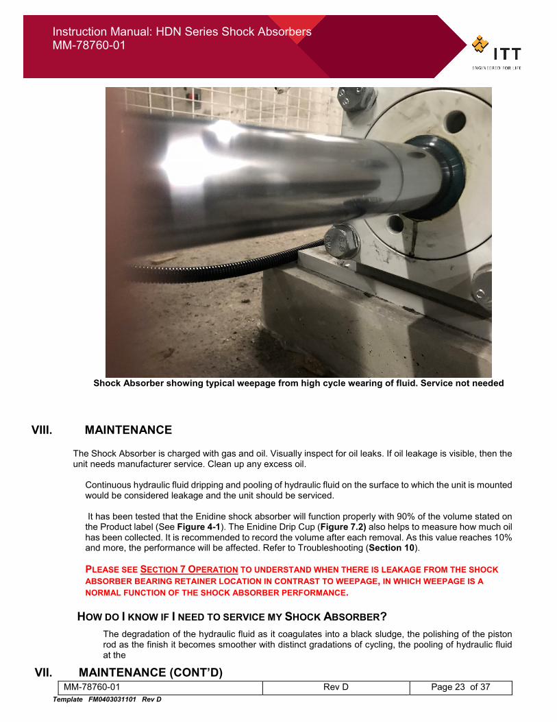
Shock Absorber showing typical weepage from high cycle wearing of fluid. Service not needed
VIII. MAINTENANCE The Shock Absorber is charged with gas and oil. Visually inspect for oil leaks. If oil leakage is visible, then the unit needs manufacturer service. Clean up any excess oil.
Continuous hydraulic fluid dripping and pooling of hydraulic fluid on the surface to which the unit is mounted would be considered leakage and the unit should be serviced. It has been tested that the Enidine shock absorber will function properly with 90% of the volume stated on the Product label (See Figure 4-1). The Enidine Drip Cup (Figure 7.2) also helps to measure how much oil has been collected. It is recommended to record the volume after each removal. As this value reaches 10% and more, the performance will be affected. Refer to Troubleshooting (Section 10).
PLEASE SEE SECTION 7 OPERATION TO UNDERSTAND WHEN THERE IS LEAKAGE FROM THE SHOCK ABSORBER BEARING RETAINER LOCATION IN CONTRAST TO WEEPAGE, IN WHICH WEEPAGE IS A NORMAL FUNCTION OF THE SHOCK ABSORBER PERFORMANCE.
HOW DO I KNOW IF I NEED TO SERVICE MY SHOCK ABSORBER?
The degradation of the hydraulic fluid as it coagulates into a black sludge, the polishing of the piston rod as the finish it becomes smoother with distinct gradations of cycling, the pooling of hydraulic fluid at the
VII. MAINTENANCE (CONT’D)
Instruction Manual: HDN Series Shock Absorbers MM-78760-01
MM-78760-01 Rev D Page 24 of 37 Template FM0403031101 Rev D
base of the shock absorber are all indicators of the life of the shock and must be considered together. The following images provide in-depth looks at the various levels of wear that the Shock Absorber can experience over the course of its usage. Please see Troubleshooting (Section 10) for further details. Shock Absorbers for emergency application: In this condition it is assumed that the shock absorber is not stroked during normal operations. For safety reasons the shock absorber should be checked for functionality at least every 12 months. Please see Inspection and Maintenance procedures later in this section. Shock absorber used for normal operation: These units should be checked visually (piston rod surface; leakage) and functionally every 6 month. Based on the cycle rate, in general after 250,000 cycles, a replacement of wearing parts could be required. In general the replacement or an overhaul of the shock absorber is recommended after at least 8 years. Please see Inspection and Maintenance procedures later in this section.
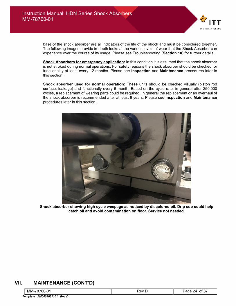
Shock absorber showing high cycle weepage as noticed by discolored oil. Drip cup could help
catch oil and avoid contamination on floor. Service not needed.
VII. MAINTENANCE (CONT’D)
Instruction Manual: HDN Series Shock Absorbers MM-78760-01
MM-78760-01 Rev D Page 25 of 37 Template FM0403031101 Rev D
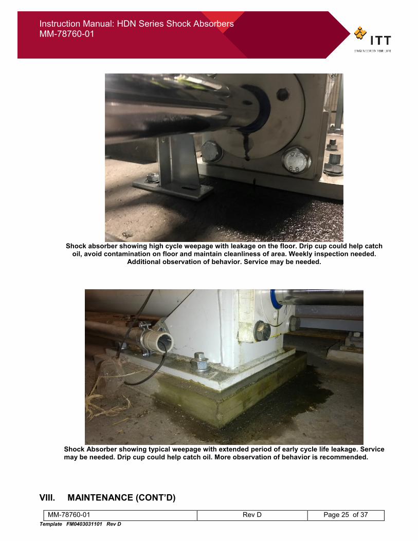
Shock absorber showing high cycle weepage with leakage on the floor. Drip cup could help catch
oil, avoid contamination on floor and maintain cleanliness of area. Weekly inspection needed. Additional observation of behavior. Service may be needed.
Shock Absorber showing typical weepage with extended period of early cycle life leakage. Service may be needed. Drip cup could help catch oil. More observation of behavior is recommended.
VIII. MAINTENANCE (CONT’D)
Instruction Manual: HDN Series Shock Absorbers MM-78760-01
MM-78760-01 Rev D Page 26 of 37 Template FM0403031101 Rev D
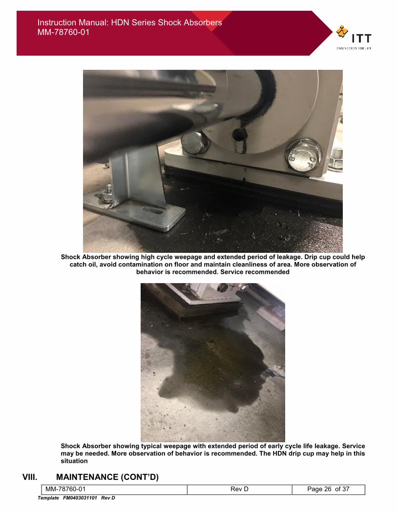
Shock Absorber showing high cycle weepage and extended period of leakage. Drip cup could help
catch oil, avoid contamination on floor and maintain cleanliness of area. More observation of behavior is recommended. Service recommended
Shock Absorber showing typical weepage with extended period of early cycle life leakage. Service may be needed. More observation of behavior is recommended. The HDN drip cup may help in this situation
VIII. MAINTENANCE (CONT’D)
Instruction Manual: HDN Series Shock Absorbers MM-78760-01
MM-78760-01 Rev D Page 27 of 37 Template FM0403031101 Rev D
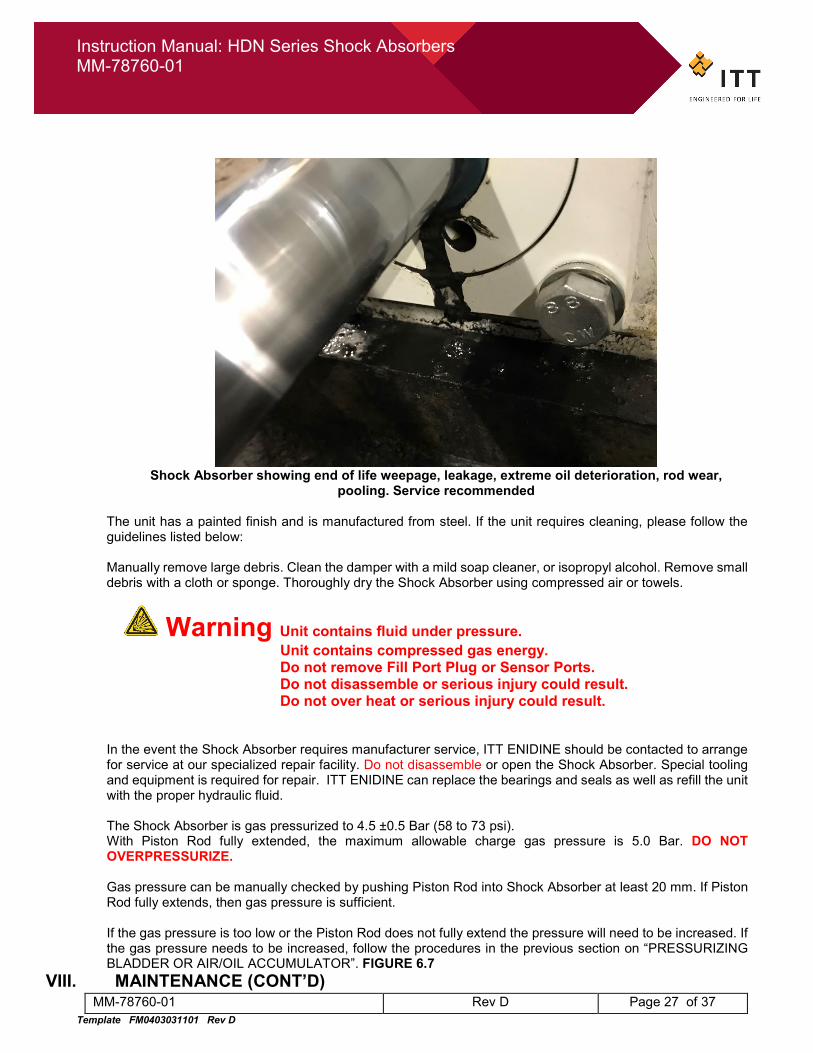
Shock Absorber showing end of life weepage, leakage, extreme oil deterioration, rod wear,
pooling. Service recommended
The unit has a painted finish and is manufactured from steel. If the unit requires cleaning, please follow the guidelines listed below:
Manually remove large debris. Clean the damper with a mild soap cleaner, or isopropyl alcohol. Remove small debris with a cloth or sponge. Thoroughly dry the Shock Absorber using compressed air or towels.
Warning Unit contains fluid under pressure. Unit contains compressed gas energy. Do not remove Fill Port Plug or Sensor Ports.
Do not disassemble or serious injury could result. Do not over heat or serious injury could result.
In the event the Shock Absorber requires manufacturer service, ITT ENIDINE should be contacted to arrange for service at our specialized repair facility. Do not disassemble or open the Shock Absorber. Special tooling and equipment is required for repair. ITT ENIDINE can replace the bearings and seals as well as refill the unit with the proper hydraulic fluid. The Shock Absorber is gas pressurized to 4.5 ±0.5 Bar (58 to 73 psi). With Piston Rod fully extended, the maximum allowable charge gas pressure is 5.0 Bar. DO NOT OVERPRESSURIZE. Gas pressure can be manually checked by pushing Piston Rod into Shock Absorber at least 20 mm. If Piston Rod fully extends, then gas pressure is sufficient. If the gas pressure is too low or the Piston Rod does not fully extend the pressure will need to be increased. If the gas pressure needs to be increased, follow the procedures in the previous section on “PRESSURIZING BLADDER OR AIR/OIL ACCUMULATOR”. FIGURE 6.7
VIII. MAINTENANCE (CONT’D)
Instruction Manual: HDN Series Shock Absorbers MM-78760-01
MM-78760-01 Rev D Page 28 of 37 Template FM0403031101 Rev D
REGULAR INSPECTION
Periodically perform a maintenance check on the Shock Absorber; frequency will depend on environment, application, and service conditions. Below is an example of a suggested inspection program:
Weekly Inspection
To insure the proper operation and performance of the Shock Absorber, inspection of the following points should be performed once per week: 1) Visually inspect the Shock Absorber for oil leakage. 2) Verify that Piston Rod fully extends when load is removed. 3) Visually inspect Piston Rod for scratches, or dents. 4) Visually inspect for any damage that would impair the safe operation of the Shock Absorber.
BIANNUAL INSPECTION To insure the proper operation and performance of the Shock Absorber, the following inspection should be performed every 6 months: 1) Fully compress the rod at low speed. 2) Release the rod; it should come back to the fully extended position in less than 30 seconds. 3) Verify that Piston Rod fully extends when load is removed. 4) Visually inspect rod seals, cylinder ends, and port plugs for oil leakage. 5) Visually inspect for any significant amounts of corrosion that could cause degradation of the
structural integrity of the product, or leakage. Note: some surface rust occurring over time is normal and can be considered acceptable, provided that it is cosmetic in nature and has not caused any significant dimensional change to the material.
6) Visually inspect for any damage that would impair the safe operation of the Shock Absorber.
VIII. MAINTENANCE (CONT’D)
Instruction Manual: HDN Series Shock Absorbers MM-78760-01
MM-78760-01 Rev D Page 29 of 37 Template FM0403031101 Rev D
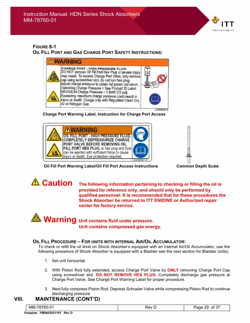
FIGURE 8-1 OIL FILL PORT AND GAS CHARGE PORT SAFETY INSTRUCTIONS:
Charge Port Warning Label, Instruction for Charge Port Access
Oil Fill Port Warning Label/Oil Fill Port Access Instructions Common Depth Scale
Caution The following information pertaining to checking or filling the oil is provided for reference only, and should only be performed by qualified personnel. It is recommended that for these procedures the Shock Absorber be returned to ITT ENIDINE or Authorized repair center for factory service.
Warning Unit contains fluid under pressure. Unit contains compressed gas energy.
OIL FILL PROCEDURE – FOR UNITS WITH INTERNAL AIR/OIL ACCUMULATOR: To check or refill the oil level on Shock Absorber’s equipped with an internal Air/Oil Accumulator, use the following procedure (if Shock Absorber is equipped with a Bladder see the next section for Bladder Units).
1. Set unit horizontal. 2. With Piston Rod fully extended, access Charge Port Valve by ONLY removing Charge Port Cap
using screwdriver slot. DO NOT REMOVE HEX PLUG. Completely discharge gas pressure at Charge Port Valve. See Charge Port Warning Label for proper procedure.
3. Next fully compress Piston Rod. Depress Schrader Valve while compressing Piston Rod to continue
discharging pressure VIII. MAINTENANCE (CONT’D)
Instruction Manual: HDN Series Shock Absorbers MM-78760-01
MM-78760-01 Rev D Page 30 of 37 Template FM0403031101 Rev D
4. ONLY AFTER Piston Rod has been fully compressed and Charge Port Valve has been FULLY
DEPRESSURIZED, proceed to remove the Oil Fill/Charge Port Plug (Hex Plug) using a wrench. See Oil Fill Port Warning Label for proper procedure.
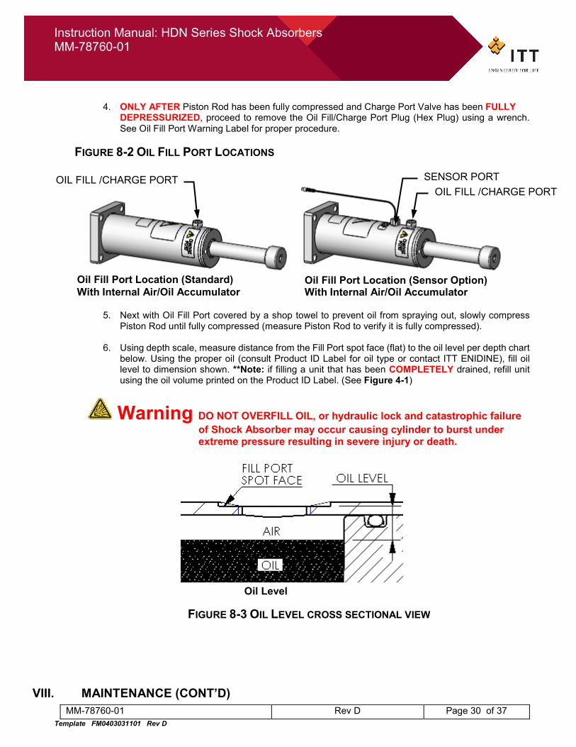
FIGURE 8-2 OIL FILL PORT LOCATIONS
5. Next with Oil Fill Port covered by a shop towel to prevent oil from spraying out, slowly compress Piston Rod until fully compressed (measure Piston Rod to verify it is fully compressed).
6. Using depth scale, measure distance from the Fill Port spot face (flat) to the oil level per depth chart
below. Using the proper oil (consult Product ID Label for oil type or contact ITT ENIDINE), fill oil level to dimension shown. **Note: if filling a unit that has been COMPLETELY drained, refill unit using the oil volume printed on the Product ID Label. (See Figure 4-1)
Warning DO NOT OVERFILL OIL, or hydraulic lock and catastrophic failure of Shock Absorber may occur causing cylinder to burst under extreme pressure resulting in severe injury or death.
FIGURE 8-3 OIL LEVEL CROSS SECTIONAL VIEW
VIII. MAINTENANCE (CONT’D)
OIL FILL /CHARGE PORT OIL FILL /CHARGE PORT
SENSOR PORT
Oil Fill Port Location (Standard) With Internal Air/Oil Accumulator
Oil Fill Port Location (Sensor Option) With Internal Air/Oil Accumulator
Oil Level
Instruction Manual: HDN Series Shock Absorbers MM-78760-01
MM-78760-01 Rev D Page 31 of 37 Template FM0403031101 Rev D
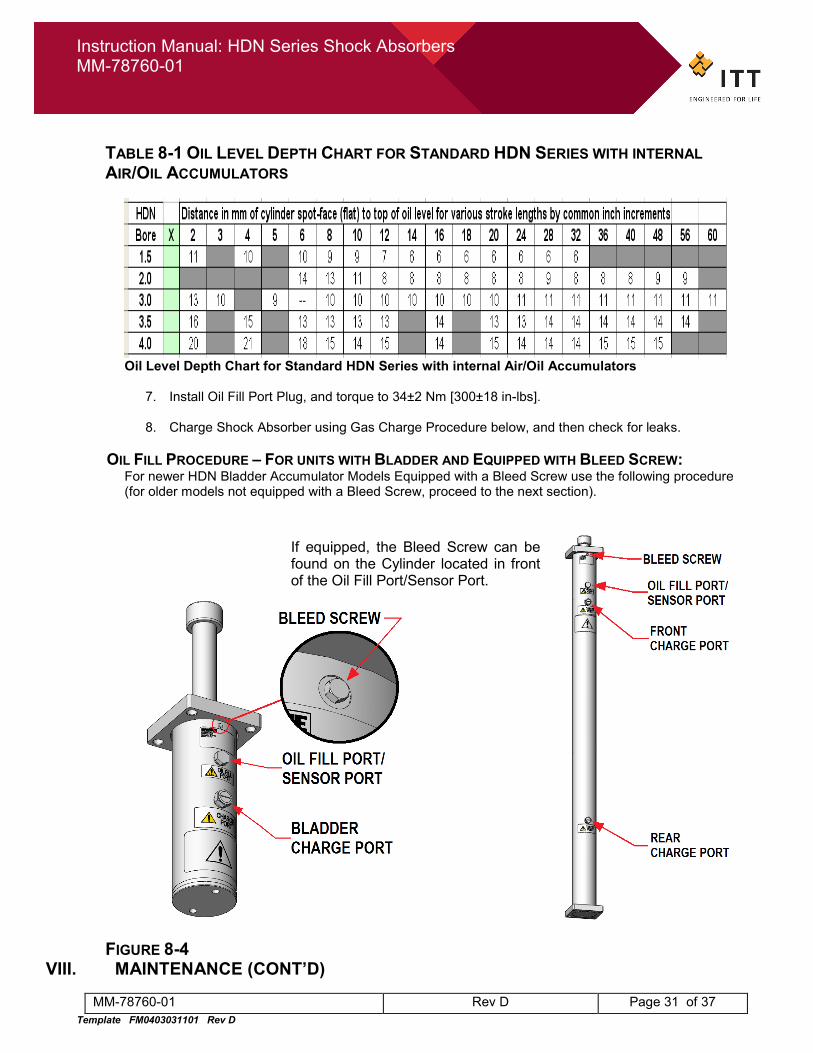
TABLE 8-1 OIL LEVEL DEPTH CHART FOR STANDARD HDN SERIES WITH INTERNAL AIR/OIL ACCUMULATORS
Oil Level Depth Chart for Standard HDN Series with internal Air/Oil Accumulators
7. Install Oil Fill Port Plug, and torque to 34±2 Nm [300±18 in-lbs].
8. Charge Shock Absorber using Gas Charge Procedure below, and then check for leaks.
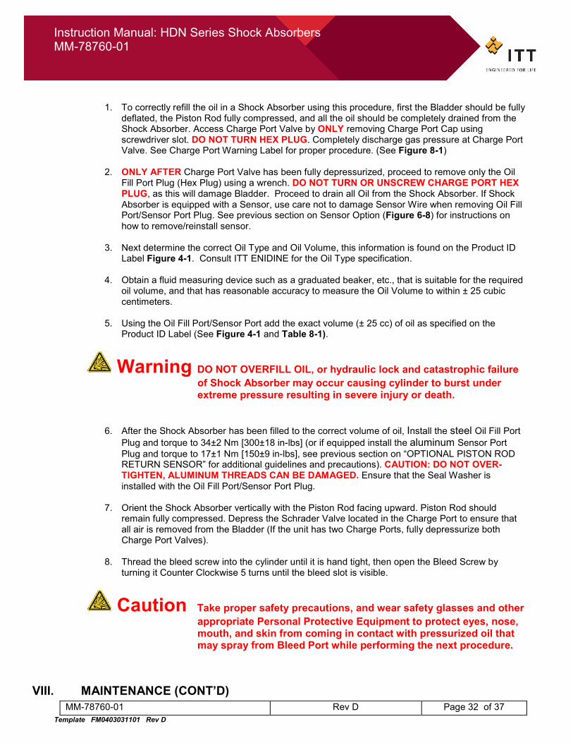
OIL FILL PROCEDURE – FOR UNITS WITH BLADDER AND EQUIPPED WITH BLEED SCREW: For newer HDN Bladder Accumulator Models Equipped with a Bleed Screw use the following procedure (for older models not equipped with a Bleed Screw, proceed to the next section).
FIGURE 8-4 VIII. MAINTENANCE (CONT’D)
If equipped, the Bleed Screw can be found on the Cylinder located in front of the Oil Fill Port/Sensor Port.
Instruction Manual: HDN Series Shock Absorbers MM-78760-01
MM-78760-01 Rev D Page 32 of 37 Template FM0403031101 Rev D
1. To correctly refill the oil in a Shock Absorber using this procedure, first the Bladder should be fully
deflated, the Piston Rod fully compressed, and all the oil should be completely drained from the Shock Absorber. Access Charge Port Valve by ONLY removing Charge Port Cap using screwdriver slot. DO NOT TURN HEX PLUG. Completely discharge gas pressure at Charge Port Valve. See Charge Port Warning Label for proper procedure. (See Figure 8-1)
2. ONLY AFTER Charge Port Valve has been fully depressurized, proceed to remove only the Oil Fill Port Plug (Hex Plug) using a wrench. DO NOT TURN OR UNSCREW CHARGE PORT HEX PLUG, as this will damage Bladder. Proceed to drain all Oil from the Shock Absorber. If Shock Absorber is equipped with a Sensor, use care not to damage Sensor Wire when removing Oil Fill Port/Sensor Port Plug. See previous section on Sensor Option (Figure 6-8) for instructions on how to remove/reinstall sensor.
3. Next determine the correct Oil Type and Oil Volume, this information is found on the Product ID Label Figure 4-1. Consult ITT ENIDINE for the Oil Type specification.
4. Obtain a fluid measuring device such as a graduated beaker, etc., that is suitable for the required
oil volume, and that has reasonable accuracy to measure the Oil Volume to within ± 25 cubic centimeters.
5. Using the Oil Fill Port/Sensor Port add the exact volume (± 25 cc) of oil as specified on the
Product ID Label (See Figure 4-1 and Table 8-1).
Warning DO NOT OVERFILL OIL, or hydraulic lock and catastrophic failure of Shock Absorber may occur causing cylinder to burst under extreme pressure resulting in severe injury or death.
6. After the Shock Absorber has been filled to the correct volume of oil, Install the steel Oil Fill Port Plug and torque to 34±2 Nm [300±18 in-lbs] (or if equipped install the aluminum Sensor Port Plug and torque to 17±1 Nm [150±9 in-lbs], see previous section on “OPTIONAL PISTON ROD RETURN SENSOR” for additional guidelines and precautions). CAUTION: DO NOT OVER-TIGHTEN, ALUMINUM THREADS CAN BE DAMAGED. Ensure that the Seal Washer is installed with the Oil Fill Port/Sensor Port Plug.
7. Orient the Shock Absorber vertically with the Piston Rod facing upward. Piston Rod should remain fully compressed. Depress the Schrader Valve located in the Charge Port to ensure that all air is removed from the Bladder (If the unit has two Charge Ports, fully depressurize both Charge Port Valves).
8. Thread the bleed screw into the cylinder until it is hand tight, then open the Bleed Screw by
turning it Counter Clockwise 5 turns until the bleed slot is visible.
Caution Take proper safety precautions, and wear safety glasses and other appropriate Personal Protective Equipment to protect eyes, nose, mouth, and skin from coming in contact with pressurized oil that may spray from Bleed Port while performing the next procedure.
VIII. MAINTENANCE (CONT’D)
Instruction Manual: HDN Series Shock Absorbers MM-78760-01
MM-78760-01 Rev D Page 33 of 37 Template FM0403031101 Rev D
9. For this next step have a rag or paper towel, and a socket wrench that fits the Bleed Screw ready
in hand. Wear Safety Glasses and take precautions to prevent pressurized oil that may spray from the Bleed Screw from coming in contact with eyes, nose or mouth. With the Shock Absorber oriented vertically (Piston Rod facing upward), and the Bleed Screw opened as per Step 8, use clean dry air (or nitrogen gas) regulated to 1 Bar [15 psi] and begin to very slowly inflate the Bladder using the Charge Port Valve. If the unit is equipped with two Charge Ports, use the Rear Charge Port for this procedure. As the Bladder is being inflated keep careful watch on the Bleed Screw, pressurized air should escape from the Bleed Screw followed by a mist of air and oil, until finally a steady air-free stream of oil begins to flow from the bleed screw (not more than 10 to 15 cc of oil should be lost during this process). As soon as a steady stream of oil just begins to flow from the bleed screw, immediately close the bleed screw and torque to 0.59±0.035 Nm [5.2±0.3 in-lbs], and stop applying air to the Charge Port. **Note: For units equipped with two Charge Ports, if the Rear Charge Port has been inflated to 1 Bar [15 psi] and Oil has not begun to flow from the Bleed Screw, move the air supply from the Rear Charge Port Valve to the Front Charge Port Valve and proceed to very slowly inflate the Front Charge Port Valve until a steady oil flow is achieved at the Bleed Screw, then immediately tighten the Bleed Screw.
10. Finally Charge the Bladder to the recommended Charge Pressure per the Product ID Label, see previous section of this Manual entitled “PRESSURIZING BLADDER OR AIR/OIL ACCUMULATOR” for proper Charging Procedure.
OIL FILL PROCEDURE – FOR UNITS WITH BLADDER THAT ARE NOT EQUIPPED WITH BLEED SCREW:
For older HDN Bladder Accumulator Models, HD and HDA Models that are NOT equipped with a Bleed Screw use the following procedure:
1. Set unit horizontal. 2. With Piston Rod fully extended, access Charge Port Valve by ONLY removing Charge Port Cap
using screwdriver slot. DO NOT TURN HEX PLUG. Completely discharge gas pressure at Charge Port Valve. See Charge Port Warning Label for proper procedure.
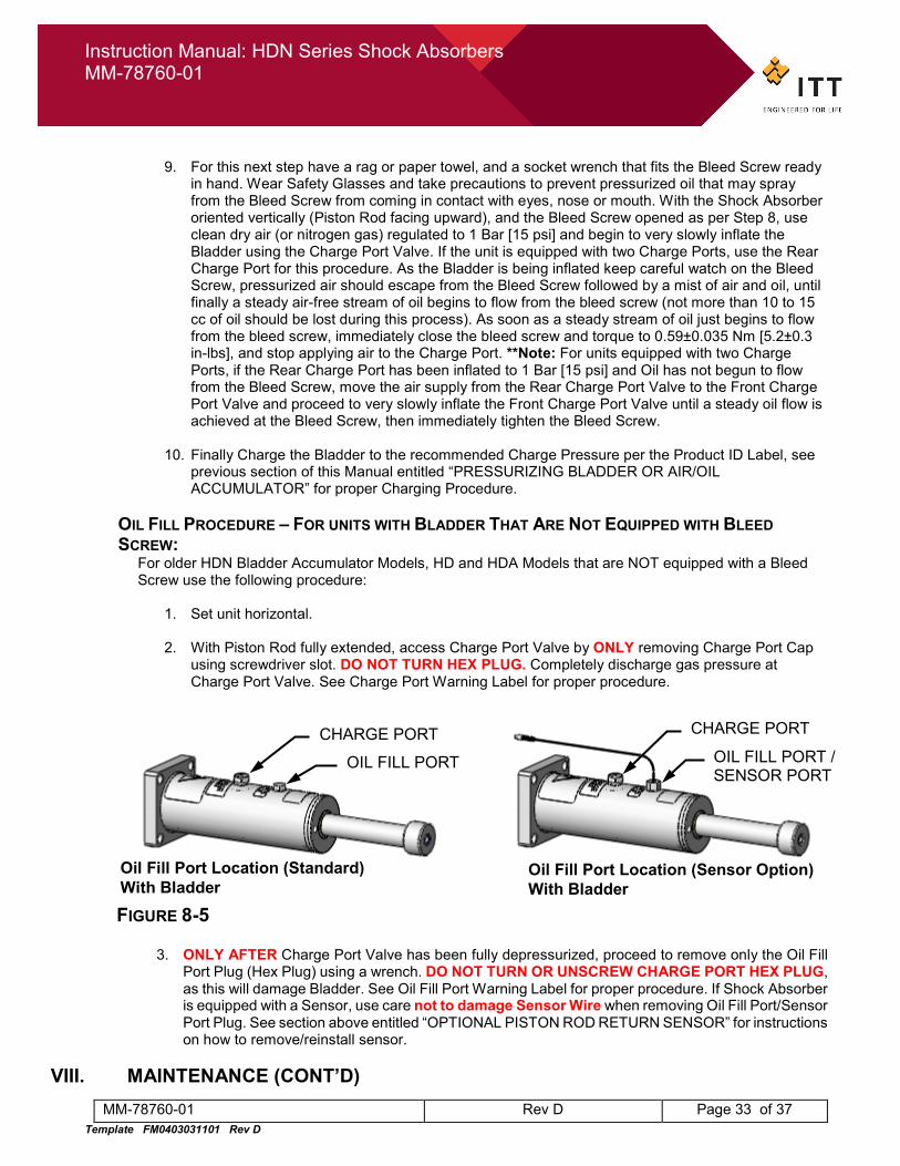
FIGURE 8-5
3. ONLY AFTER Charge Port Valve has been fully depressurized, proceed to remove only the Oil Fill Port Plug (Hex Plug) using a wrench. DO NOT TURN OR UNSCREW CHARGE PORT HEX PLUG, as this will damage Bladder. See Oil Fill Port Warning Label for proper procedure. If Shock Absorber is equipped with a Sensor, use care not to damage Sensor Wire when removing Oil Fill Port/Sensor Port Plug. See section above entitled “OPTIONAL PISTON ROD RETURN SENSOR” for instructions on how to remove/reinstall sensor.
VIII. MAINTENANCE (CONT’D)
Oil Fill Port Location (Sensor Option) With Bladder
OIL FILL PORT / SENSOR PORT
OIL FILL PORT
Oil Fill Port Location (Standard) With Bladder
CHARGE PORT CHARGE PORT
Instruction Manual: HDN Series Shock Absorbers MM-78760-01
MM-78760-01 Rev D Page 34 of 37 Template FM0403031101 Rev D
4. Only after Oil Fill Port Plug has been removed, using an air or nitrogen supply line that is regulated
at 1 Bar (15 psi) to provide a slow flow of gas, inflate Bladder to 1 Bar (15 psi). Note: Some oil may spill out of fill port as Bladder in inflated. Charging Bladder too quickly will cause oil to spray out of fill port.
5. With Bladder charged to 1 Bar (15 psi), and Oil Fill Port Plug removed, check oil level. Oil should
be filled flush to top of Oil Fill Port. If needed add the proper oil (consult Product ID Label for Oil Type or contact ITT ENIDINE) to Oil Fill Port until oil level is flush with top of Oil Fill Port. WARNING: MAKE CERTAIN THAT BLADDER IS FULLY EXPANDED AND CHARGED TO 1 BAR (15 PSI) BEFORE ADDING OIL, OTHERWISE TOO MUCH OIL WILL FILL CYLINDER AND BLADDER WILL NOT PROVIDE PROPER ACCUMULATION, CAUSING SHOCK ABSROBER TO HYDRAULIC LOCK DURING IMPACT, RESULTING IN CATASTROPHIC FAILURE, AND MAY RESULT IN DEATH OR INJURY.
Warning DO NOT OVERFILL OIL, or hydraulic lock and catastrophic failure of Shock Absorber may occur causing cylinder to burst under extreme pressure resulting in severe injury or death.
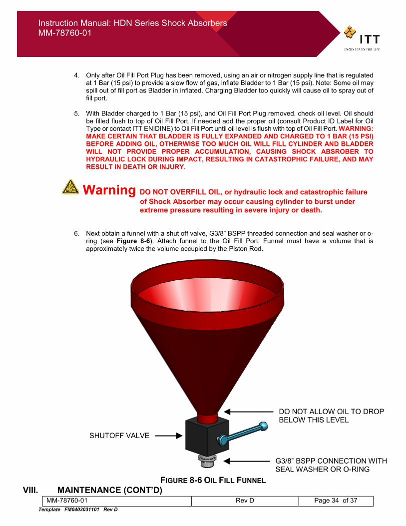
6. Next obtain a funnel with a shut off valve, G3/8” BSPP threaded connection and seal washer or o-ring (see Figure 8-6). Attach funnel to the Oil Fill Port. Funnel must have a volume that is approximately twice the volume occupied by the Piston Rod.
FIGURE 8-6 OIL FILL FUNNEL
VIII. MAINTENANCE (CONT’D)
DO NOT ALLOW OIL TO DROP BELOW THIS LEVEL
SHUTOFF VALVE
G3/8” BSPP CONNECTION WITH SEAL WASHER OR O-RING
Instruction Manual: HDN Series Shock Absorbers MM-78760-01
MM-78760-01 Rev D Page 35 of 37 Template FM0403031101 Rev D
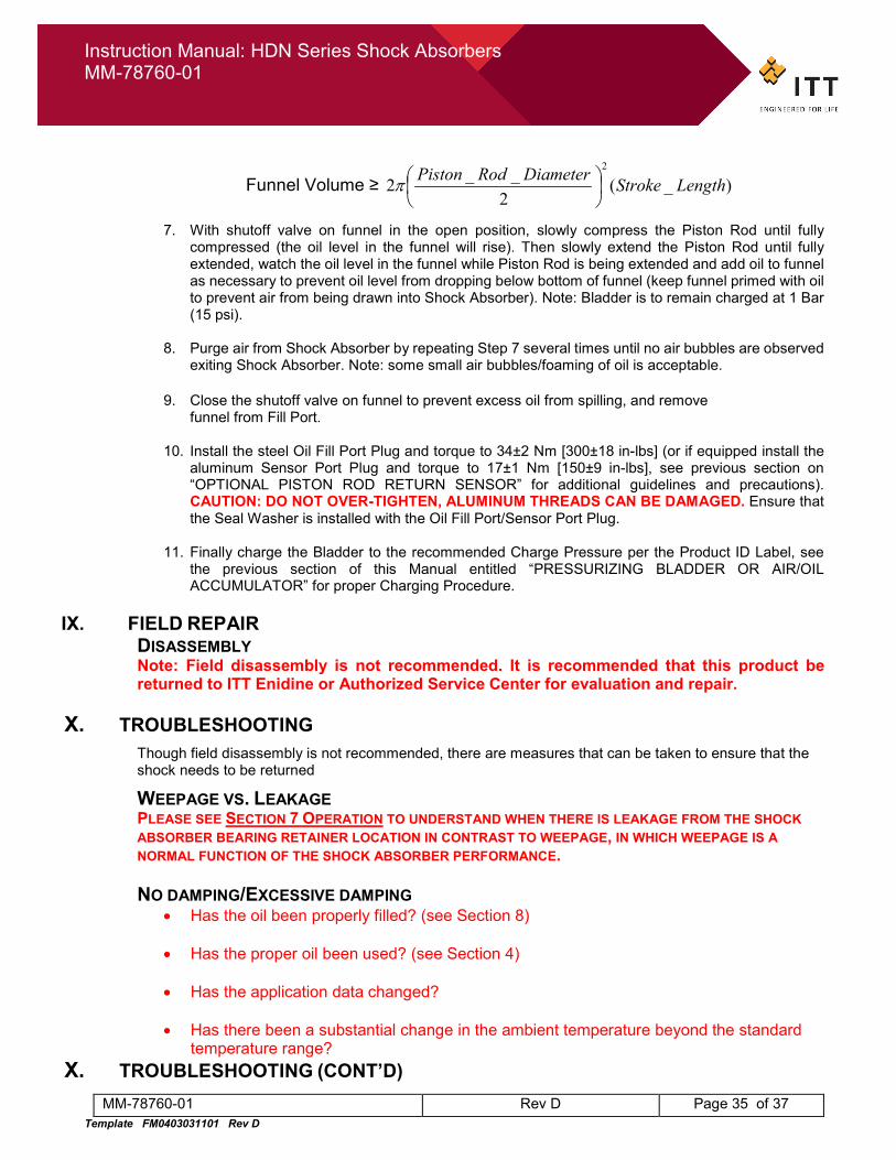
Funnel Volume ≥ )_(2
__22
LengthStrokeDiameterRodPiston
π
7. With shutoff valve on funnel in the open position, slowly compress the Piston Rod until fully compressed (the oil level in the funnel will rise). Then slowly extend the Piston Rod until fully extended, watch the oil level in the funnel while Piston Rod is being extended and add oil to funnel as necessary to prevent oil level from dropping below bottom of funnel (keep funnel primed with oil to prevent air from being drawn into Shock Absorber). Note: Bladder is to remain charged at 1 Bar (15 psi).
8. Purge air from Shock Absorber by repeating Step 7 several times until no air bubbles are observed
exiting Shock Absorber. Note: some small air bubbles/foaming of oil is acceptable.
9. Close the shutoff valve on funnel to prevent excess oil from spilling, and remove funnel from Fill Port.
10. Install the steel Oil Fill Port Plug and torque to 34±2 Nm [300±18 in-lbs] (or if equipped install the
aluminum Sensor Port Plug and torque to 17±1 Nm [150±9 in-lbs], see previous section on “OPTIONAL PISTON ROD RETURN SENSOR” for additional guidelines and precautions). CAUTION: DO NOT OVER-TIGHTEN, ALUMINUM THREADS CAN BE DAMAGED. Ensure that the Seal Washer is installed with the Oil Fill Port/Sensor Port Plug.
11. Finally charge the Bladder to the recommended Charge Pressure per the Product ID Label, see
the previous section of this Manual entitled “PRESSURIZING BLADDER OR AIR/OIL ACCUMULATOR” for proper Charging Procedure.
IX. FIELD REPAIR
DISASSEMBLY Note: Field disassembly is not recommended. It is recommended that this product be returned to ITT Enidine or Authorized Service Center for evaluation and repair.
X. TROUBLESHOOTING Though field disassembly is not recommended, there are measures that can be taken to ensure that the shock needs to be returned
WEEPAGE VS. LEAKAGE PLEASE SEE SECTION 7 OPERATION TO UNDERSTAND WHEN THERE IS LEAKAGE FROM THE SHOCK ABSORBER BEARING RETAINER LOCATION IN CONTRAST TO WEEPAGE, IN WHICH WEEPAGE IS A NORMAL FUNCTION OF THE SHOCK ABSORBER PERFORMANCE. NO DAMPING/EXCESSIVE DAMPING
• Has the oil been properly filled? (see Section 8)
• Has the proper oil been used? (see Section 4)
• Has the application data changed?
• Has there been a substantial change in the ambient temperature beyond the standard temperature range?
X. TROUBLESHOOTING (CONT’D)
Instruction Manual: HDN Series Shock Absorbers MM-78760-01
MM-78760-01 Rev D Page 36 of 37 Template FM0403031101 Rev D
THE PISTON ROD IS NOT FULLY EXTENDING
• Can the piston rod be fully extended with assistance?
• Is there any debris lodged in the area of the piston rod that could impede movement?
• Has the Enidine HDN shock absorber been charged to max pressure?
• Does the shock have the right amount of oil? Has more than 10% leaked out or been removed due to weepage?
THE PISTON ROD IS “STICKING”, “JERKING”, “HESITATING” • Is there any debris lodged in the area of the piston rod that could impede movement?
• Possible manufacturing issue with the concentricity of the piston head. Needs to be re-
assembled with the piston head in the correct position
• Inspect piston rod surface for debris and component wear
THE PISTON ROD IS EXTENDING AT AN ACCELERATED RATE (BA OPTION ONLY)
• Has the charge been exceeded? Internal bladder accumulator could have been damaged. Check pressure. If the reading is erratic, possible bladder issue.
• Is there a greater noise when the piston rod fully extends or fully compressed then previously observed?
• Has the ambient temperature changed?
• Possible manufacturing issue with the bladder. Do not disassemble
HIGH-PITCHED NOISE DURING EXTENSION/COMPRESSION OF PISTON ROD(BA OPTION ONLY)
• Has the charge been exceeded? Internal bladder accumulator could have been damaged. Check pressure. If the reading is erratic, possible bladder issue.
• Possible manufacturing issue with the bladder. Do not disassemble SENSOR NOT WORKING PROPERLY (IF APPLICABLE) Rotate piston rod slowly and observe if a signal is generated. If there is constant and repetitive dead band, the magnetic strip needs to be replaced. Send to factory
XI. DISPOSAL
Instruction Manual: HDN Series Shock Absorbers MM-78760-01
MM-78760-01 Rev D Page 37 of 37 Template FM0403031101 Rev D
No hazardous materials are in this product. Contact your local recycling center for proper disposal of steel, aluminum, bronze, and hydraulic oil.
Warning Unit contains fluid under pressure. Depressurize before recycling.
XII. CONTACT INFORMATION For assistance please contact:
MANUFACTURER:
ITT Enidine Incorporated Telephone: 716-662-1900 7 Centre Drive Telefax: 716-662-8289 Orchard Park, NY 14127 www.itt.com USA www.enidine.com


![Hdn 1dc Hdn 2dc Hdn 3dc [Rev 3 0] Ru Web](https://img.pdfslide.net/doc/110x75/55cf9823550346d03395cc06/hdn-1dc-hdn-2dc-hdn-3dc-rev-3-0-ru-web.jpg)