Embed Size (px)
Citation preview

E SERIES ENTASYS 200
VERSATILE TWO-WAY COLUMN ARRAY SYSTEMS
INSTALLATION / OPERATION MANUAL

ENTASYS 200 Installation/Operation Manual — Page 2
EC STATEMENT OF CONFORMITY
This document confirms that the range of products of Community Professional Loudspeakers bearing the CE label meets all of the requirements in the EMC directive 89/336/EEC laid down by the Member States Council for adjustment of legal requirements. Furthermore, the products comply with the rules and regulations referring to the electromagnetic compatibility of devices from 30-August-1995.
The Community Professional Loudspeaker products bearing the CE label comply with the following harmonized or national standards:
DIN EN 55013:08-1991 DIN EN 55020:05-1995 DIN EN 55082-1:03-1993
The authorized declaration and compatibility certification resides with the manufacturer and can be viewed upon request. The responsible manufacturer is the company:
Community Light & Sound 333 East Fifth Street Chester, PA 19013 USA TEL: 1-610 876-3400 FAX: 1-610 874-0190
EC Statement of Conformity

ENTASYS 200 Installation/Operation Manual — Page 3
WARRANTY INFORMATION
Community ENTASYS 200 loudspeakers and accessories are warranted in the USA to be free from defects in materials and workmanship for a period of five (5) years, as determined by one of the following two methods, whichever is longer:
1. Starting from the date of retail purchase, as noted on the sales receipt from an authorized Community dealer,
OR
2. Starting from the date of manufacture, determined by the serial number, if the sales receipt is not available.
Transferable Warranty “Limited”
For complete warranty information please refer to the Warranty Card enclosed with the product or the Community website (www.communitypro.com). Please call 610-876-3400 to locate your nearest Authorized Field Service Station. For Factory Service call 610-876-3400. You must obtain a Return Authorization (R/A) number prior to the return of your product for factory service.
Warranty Information and Service for Countries Other Than the USA
To obtain specific warranty information and available service locations for countries other than the United States of America, contact the authorized Community Distributor for your specific country or region.
Welcome to Community
ENTASYS 200 Installation/Operation Manual — Page 4
UNPACKING AND INSPECTION ENTASYS 200 loudspeakers are carefully packed in sturdy cartons. However, it’s wise to thoroughly inspect each unit after it has been removed from the packaging, as damage may have occurred during shipping. SHIPPING CLAIMS If the product is damaged during transit you must file a damage claim directly with the freight company. Be sure to save the carton and packing materials, as damage claims can be denied if these materials are not retained. If evidence of physical damage exists upon arrival, be cautious before signing a delivery acceptance receipt. Often the fine print will waive your right to file a claim for damage or loss after you sign it. Make sure that the numbers of cartons shown on the freight documents have actually been delivered.
It’s always a good idea to retain the carton and packing materials indefinitely, if possible, in the event that the unit may need to be returned to your dealer or distributor for repair in the future. IN THE CARTON
Unpacking and Inspection
Carton Contents: One (1) Column Loudspeaker (model ENT203, 206, 212 or 220) One (1) Pan-Tilt Mount Bracket (Assembled) One (1) Operation and Installation Manual One (1) Warranty Card
Listed below are additional contents included in the carton for each model noted.
Models ENT203/ENT206 contains the following hardware in one bag: Four (4) 3.5x16mm Phillips Truss Head Deep Thread Screws SS One (1) Safety Cable Bracket (black or white) One (1) Input Cover (black or white) Four (4) 2.5x16mm Phillips Flat Head Sheet Metal Screws SS
Models ENT212/ENT220 includes (2) Side Arm Clamps, and the following hardware in one bag: Four (4) 3.5x16mm Phillips Truss Head Deep Thread Screws SS One (1) Safety Cable Bracket (black or white) One (1) Input Cover (black or white) Four (4) 2.5x16mm Phillips Flat Head Sheet Metal Screws SS (2) M5x30 Hex Head Screws SS (2) M5 Hex Nuts SS (2) 5mm Lock Washers SS (4) 5mm Flat Washers SS

ENTASYS 200 Installation/Operation Manual — Page 5
Getting Acquainted
INTRODUCTION Thank you for your selection of Community’s ENTASYS 200 Series Column Array Loudspeakers. The ENTASYS 200 family features controlled, narrow vertical directivity with wide horizontal coverage. They are easy to install and each model provides excellent sound quality in its size and class.
This manual is intended to help you install and use ENTASYS 200 loudspeakers safely and effectively. It provides useful information to help you obtain the best performance, sound quality, and reliability from your ENTASYS 200 system. We recommend that you read the entire manual before beginning your installation.
ENTASYS Features and Technology
ENTASYS 200 Series loudspeakers offer numerous features and technologies that provide unprecedented sonic quality and installation flexibility. Some of these include:
Unique two-way, full-range column array loudspeakers with advanced passive crossover technology.
All models are weather-resistant.
All models are available in black or white.
All models are equipped with built-in autoformers with multiple taps for each loudspeaker. Nothing external needs to be added to install a constant-voltage system.
Compact Ribbon Emulator high frequency elements provide narrow, well-behaved vertical directivity control.
High frequency drivers use sealed polymer frames and diaphragms for inherent weather-resistance.
Low frequency drivers have a 100% urethane impregnated cone with a large polymer dust cap covering the voice coil for weather-resistance.
Unique dynamic protection circuitry helps protect the system.
Protective steel grilles and mounting brackets are covered with a rugged, dual-layer powder coat finish for superior resistance to weather.
Mounting brackets are included with each model to suit most applications.
Optional mounting brackets are available for portable applications and for use with third-party mounting devices.

ENTASYS 200 Installation/Operation Manual — Page 6
EC Statement of Conformity ......................................................................................................................................... Page 2 Warranty Information ...................................................................................................................................................... Page 3 Table of Contents ............................................................................................................................................................... Page 4 Important Safety Information (Rigging & Electrical Safety) ........................................................................ Page 5 Unpacking and Inspection
Unpacking and Inspection ................................................................................................................................ Page 6 Shipping Claims .................................................................................................................................................... Page 6 What’s in the Carton ........................................................................................................................................... Page 6
Getting Acquainted Introduction ........................................................................................................................................................... Page 7 ENTASYS 200 Features and Technology ..................................................................................................... Page 7 ENTASYS 200 Models ......................................................................................................................................... Page 8 General Description ............................................................................................................................................ Page 9
Basic Specifications Performance Specifications ........................................................................................................................... Page 10 Physical Specifications .................................................................................................................................... Page 10
Product Drawings Top, Bottom, Cover Plate and Brackets (typical) .................................................................................... Page 11
Installation Electrical Installation and Safety ................................................................................................................. Page 12 Electrical Connections and Cabling ............................................................................................................. Page 12 Outdoor Installations; Minimum Downward Tilt Angle ....................................................................... Page 12 Mechanical Installation and Safety ................................................................................................ Pages 12 - 13 External High-Pass Filters ............................................................................................................................. Page 13 Installing the ENT 203 and ENT 206 Pan-Tilt Bracket ............................................................. Pages 14 - 15 Installing the ENT 212 and ENT 220 Pan-Tilt Bracket .............................................................. Pages 15 - 18 Using ENTASYS 200 Optional Brackets ......................................................................................... Pages 19 - 20
Autoformer Taps and Additional Electrical Terminations Autoformer Input Labels and Terminal Strip Connectors .................................................................. Page 21 Polarity and Pin Designations ..................................................................................................................... Page 22 Wiring Neutrik NL4® Connectors ................................................................................................................ Page 22 Recommended Cable Gauge ......................................................................................................................... Page 22
Interfacing with Amplifiers Recommended Amplifier Power ................................................................................................................. Page 23 Connecting Multiple Loudspeakers to a Single Amplifier Channel ................................................ Page 23
Rigging and Suspension Safety ................................................................................................................................ Page 24 Guidelines for Using ENTASYS 200 Outdoors .................................................................................................. Page 25 Field Service ...................................................................................................................................................................... Page 25 Painting ENTASYS 200 Loudspeakers ........................................................................................................ Pages 26 - 27
Table of Contents

ENTASYS 200 Installation/Operation Manual — Page 7
IMPORTANT SAFETY INFORMATION Always follow these safety precautions when using or installing ENTASYS 200 loudspeakers and accessories:
Read and keep these instructions.
Heed all warnings.
Follow all instructions, particularly those pertaining to rigging, mounting, hanging, and electrical connections.
Only use accessories that are specified and approved by Community. The terms IMPORTANT, WARNING, and DANGER, as used in this manual, alert the reader to important safety considerations. If you have any questions or do not understand the meaning of these terms, do not proceed with installation. Contact your local dealer, distributor, or call Community directly for assistance.
IMPORTANT: describes an operating condition or user action that may expose the equipment or user to potential damage or danger.
WARNING: describes an operating condition or user action that will likely cause damage to the equipment or injury to the user or to others in the vicinity.
DANGER: describes an operating condition or user action that will immediately damage the equipment and/or be extremely dangerous or life threatening to the user or to others in the vicinity.
RIGGING AND ELECTRICAL SAFETY
DANGER: The loudspeakers described in this manual are designed and intended to be mounted using a variety of rigging hardware, means and methods. Installation of loudspeakers should only be performed by trained and qualified personnel. It is strongly recommended that a licensed and certified professional structural engineer approve the mounting plan. Severe injury and/or loss of life may occur if these products are improperly installed!
DANGER: All rigging fittings must be fully tightened and secured. Any missing fasteners will compromise the structural integrity of the enclosure and constitute a safety hazard. Do not suspend this loudspeaker unless all fasteners are securely in place!
IMPORTANT: Refer to the sections on installation and connections later in this manual for additional information on rigging and electrical safety.
DANGER: It is possible to experience severe electrical shock from a power amplifier. Always make sure that all power amplifiers are in the “OFF” position and unplugged from an AC Mains supply before performing electrical work.
Important Safety information
ENTASYS 200 Installation/Operation Manual — Page 8
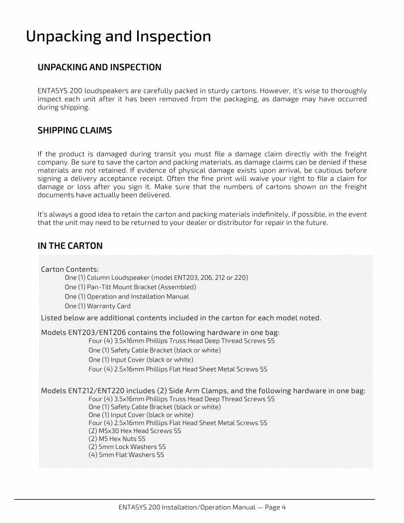
Getting Acquainted ENTASYS 200 MODELS The four ENTASYS models are pictured below with their included brackets attached. In descending size they are the ENT220, the ENT212, the ENT206 and the ENT203. The model numbers refer to the number of woofers that are contained in each unit.

ENTASYS 200 Installation/Operation Manual — Page 9
Getting Acquainted General Description The ENTASYS 200 family is comprised of four models of compact and attractive column array type loudspeakers. All four models are available in a glossy white or black finish, or may be painted to match a specific room décor (see pages 26 and 27 for painting instructions).
Construction is of thick, heavily reinforced extruded PVC, with a metal grille coated with our dual-layer powder-coat process. All models feature 80mm woofers with a separate Compact Ribbon Emulator High Frequency array that we call a “CRE”.
All models are inherently weather-resistant and each is equipped with a built-in 70V/100V autoformer with five wattage taps and one low impedance input. Additionally, a NL4-type low impedance input is provided as a standard feature, useful for portable applications.
The differences from model to model include the number of woofers, the number of high frequency CRE arrays, the power taps of the built-in autoformer, and the addition of woofer ’shading’ in the ENT212 and ENT220. The four models are summarized below:
ENT203: 3 LF Drivers, 1 High Frequency CRE array, 2-way crossover ENT206: 6 LF Drivers, 2 High Frequency CRE arrays, 2-way crossover ENT212: 12 LF Drivers, 4 High Frequency CRE arrays, frequency shaded 4-way crossover ENT220: 20 LF Drivers, 4 High Frequency CRE arrays, frequency shaded 5-way crossover
Typical usage includes music and speech reinforcement in venues such as houses-of-worship, clubs, restaurants, scholastic and corporate auditoria; paging in airports and other transit stations; coverage of concourse areas in sports facilities, and much more. All models can be used alone as the primary sound source, or as part of a larger system comprised of other models and/or other types of loudspeakers, providing fill where additional acoustic support may be required.
The tight pattern control in the vertical axis makes it easy to tame difficult acoustical conditions such as excess reverberation, while the wide, 140° horizontal dispersion means fewer loudspeakers are needed to cover a given area. The small size and pleasing shape allow these loudspeakers to be mounted in locations where traditional point-source loudspeakers might not fit, or would not visually be acceptable within a given room décor.
While all four models provide tight, highly directional pattern control at mid and high frequencies, the longer models will provide directional pattern control in the vertical axis at lower frequencies in proportion to their length. Please note that unlike Community’s modular ENTASYS (ENT-FR/ENT-LF) system, ENTASYS 200 models are NOT intended to be coupled together to form longer line sources. When low frequency control is important, the ENT220 is long enough for many demanding applications, while the ENT212 provides well-controlled LF in standard applications. The two smaller models, the ENT206 and ENT203 are intended to provide supplemental fill and/or to serve as the main systems in environments that are not acoustically challenging in respect to low frequency pattern control.
The two larger models (ENT220 and ENT212) are supplied with a mounting bracket appropriate for their size and weight, while the two smaller models (ENT206 and ENT203) share a smaller-sized mounting bracket. Both mounting brackets permit a range of vertical and horizontal adjustments.
A weather cover with a half-inch (1/2”) conduit knock-out is provided for installations in inclement weather conditions and to protect the input terminals. Note that when the weather cover is in place, the NL4-type connector cannot be used (only the terminal strip is accessible), and the range of vertical adjustment may be slightly reduced. Each model is also equipped with a high-strength eye-bolt at the top of the column, intended to be used as a safety cable attachment point whenever the loudspeaker is mounted to a wall.
Optional accessories include a Stand Adaptor (E200-SAK) that adapts the mounting bracket to a typical loudspeaker support stand, and a Universal Mounting Kit (E200-UMK) that permits the use of third-party mounting products.
ENTASYS 200 Installation/Operation Manual — Page 10
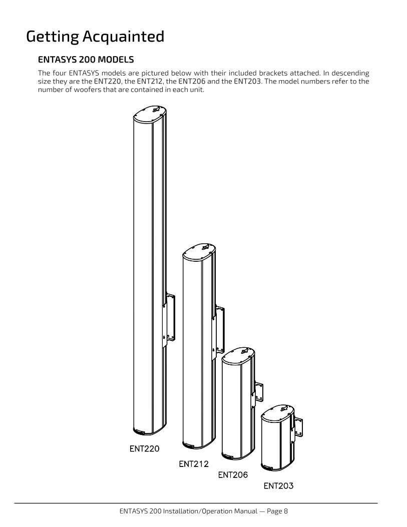
Basic Specifications ENTASYS 200 SERIES PERFORMANCE SPECIFICATIONS
Impedance Power Handling
Continuous
Autoformer Taps (W)
Sensitivity (1W/1m)
Max Output (1m)
ENT203 16 75W 30, 15, 7.5, 3.75, 1.88
92dB
111 dB 117 dB Peak (1/2 space)
ENT206 8 150W 60, 30, 15, 7.5, 3.75
93dB
115 dB 121 dB Peak (1/2 space)
ENT212 8 325W 120, 60, 30, 15, 7.5
96dB
121 dB 127 dB Peak (1/2 space)
ENT220 8 500W 120, 60, 30, 15, 7.5
97dB
124 dB 130 dB Peak (1/2 space)
ENTASYS 200 SERIES PHYSICAL SPECIFICATIONS
Height Width Depth Weight
(Including yoke)
ENT203 10.3 inches
262 mm
4.62 inches
117 mm
7.47 inches
189 mm
9 lbs.
4.1 kg.
ENT206 19.9 inches
506 mm
4.62 inches
117 mm
7.47 inches
189 mm
15 lbs.
6.8 kg.
ENT212 39.1 inches
993 mm
4.62 inches
117 mm
7.47 inches
189 mm
28 lbs.
12.7 kg.
ENT220 64.6 inches
1643 mm
4.62 inches
117 mm
7.47 inches
189 mm
41 lbs.
18.6 kg.
ENTASYS 200 Installation/Operation Manual — Page 11
ENT203 IMPEDANCE: 16 OHM
POWER: 75W RMS
190W PGM
NL4: 1+/- IN
2+/- N.C.
*NOTE: NL4 FOR 16 OHM
INPUT ONLY
JUMPER (REMOVE FOR 16 OHM)
16 OHM INPUT
COMMON
70V
1.88W
3.75W
7.5W
15W
30W
100V
3.75W
7.5W
15W
30W
N.C.
2011
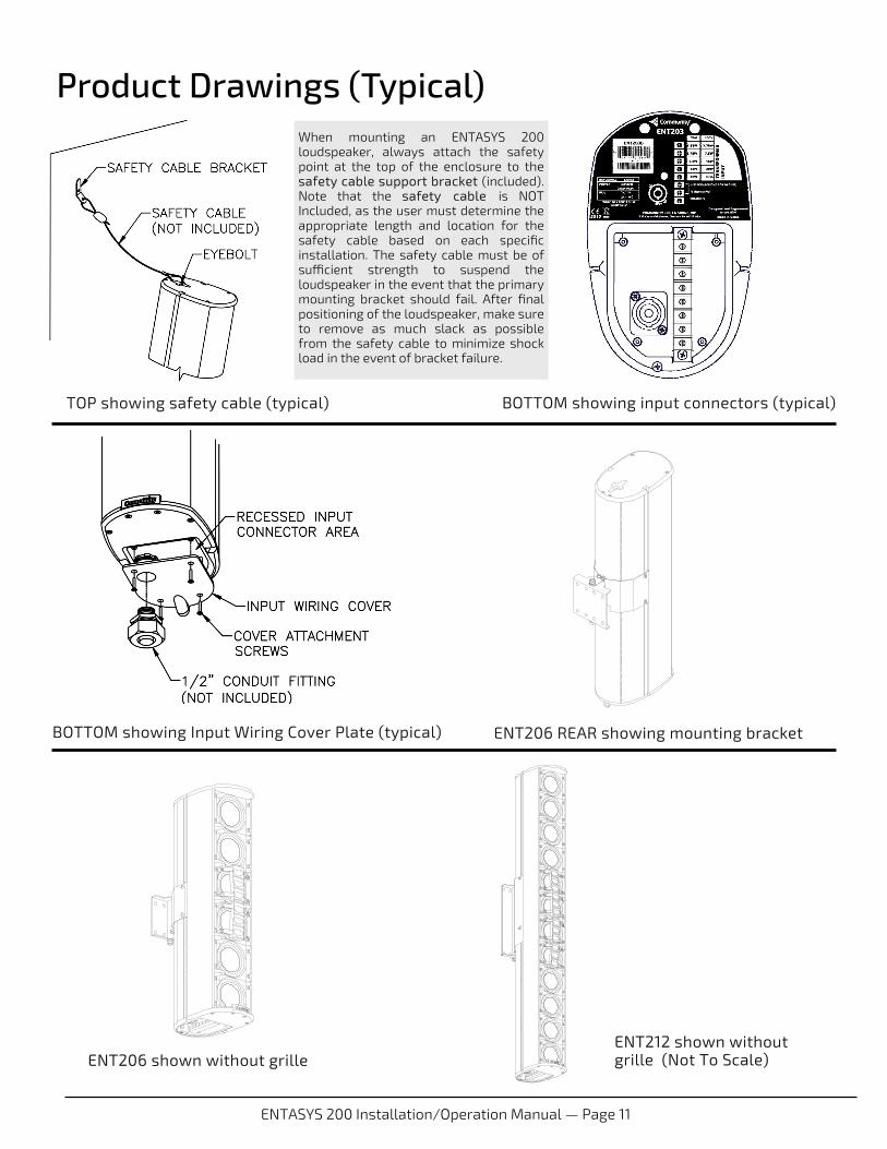
Product Drawings (Typical)
TOP showing safety cable (typical) BOTTOM showing input connectors (typical)
BOTTOM showing Input Wiring Cover Plate (typical) ENT206 REAR showing mounting bracket
ENT206 shown without grille ENT212 shown without grille (Not To Scale)
When mounting an ENTASYS 200 loudspeaker, always attach the safety point at the top of the enclosure to the safety cable support bracket (included). Note that the safety cable is NOT Included, as the user must determine the appropriate length and location for the safety cable based on each specific installation. The safety cable must be of sufficient strength to suspend the loudspeaker in the event that the primary mounting bracket should fail. After final positioning of the loudspeaker, make sure to remove as much slack as possible from the safety cable to minimize shock load in the event of bracket failure.

ENTASYS 200 Installation/Operation Manual — Page 12
ELECTRICAL INSTALLATION AND SAFETY
Electrical Safety DANGER: The output power capabilities of audio amplifiers present a danger to installers especially in 70-volt and 100-volt distributed systems. To minimize the risk of electric shock from loudspeaker connecting cables, confirm that the power amplifiers are turned “off” before connecting loudspeaker cable(s) to the loudspeaker or amplifier. Always follow local electrical codes and proper electrical safety procedures.
Electrical Connections and Cabling Input signal cabling for ENTASYS 200 Series loudspeakers can be connected to either the NL4-type connector, or to the input terminal strip on the bottom of the loudspeaker. A weather-resistant cover (included) can be attached to protect the input terminal connectors from moisture and debris. When the cover is in place, the NL4 connector cannot be used, and the range of vertical motion when wall-mounted with the accompanying bracket mounting kit may be limited slightly.
Cables, conduit, or liquid-tight couplings can be accommodated via the knock-out in the cover. A 1/2- inch NPT conduit knock-out is provided to accommodate conduit, gland nuts, strain relief fittings, etc.
Outdoor Installations—Minimum Downward Installation Angle
NOTE: Whenever ENTASYS 200 loudspeakers are installed outdoors, or exposed to direct rain, other precipitation, or cleaning water, the loudspeaker enclosure must be angled downward at a minimum of 2º (two-degrees) to meet the specified IP Rating and minimize water entry.
MECHANICAL INSTALLATION AND SAFETY
Rigging and Safety Provisions All ENTASYS 200 models are designed to be mounted using only the included or optional ENTASYS rigging hardware. An appropriately sized Pan-Tilt wall bracket is provided with each ENTASYS 200 model. Bracket ships attached to the loudspeaker, loosely assembled.
To suspend an ENTASYS 200 loudspeaker the Pan-Tilt Bracket should first be removed from the loudspeaker. Next the Pan/Tilt Bracket should be attached to the wall surface and adjusted to the desired estimated aiming angle. This is important, as it is easier and quicker to adjust the Pan-Tilt Bracket before the loudspeaker has been installed. Detailed instructions are provided on Pages 14 through 18. Lastly, install the ENTASYS 200 loudspeaker in the Pan-Tilt Bracket. Pilot holes are provided in several locations for fastening the loudspeaker to the Pan-Tilt Bracket, but it is also possible to attach the loudspeaker in other locations along the length of the extrusion, in order to derive the desired placement and vertical range of motion. Care should be given to ensure the Pan-Tilt bracket is placed as high on the cabinet that the focus angle will allow but not higher than necessary to ensure a secure and stable installation. Ensure that all four included 3.5x16mm Phillips Truss Head Screws are used when securing the Pan-Tilt Bracket to the cabinet. Once the ENTASYS 200 loudspeaker is installed in the Pan-Tilt Bracket and the focus angle is adjusted, fully tighten each of the 3.5x16mm Phillips Truss Head Screws to fully secure the loudspeaker to the Pan-Tilt Bracket.
Installation

ENTASYS 200 Installation/Operation Manual — Page 13
Installation
WARNING: It is essential that all installation work involving the suspension of these loudspeaker products be performed by competent, knowledgeable persons who understand safe rigging practices. Severe injury and/or loss of life may occur if these products are improperly installed.
DANGER: It is essential that a safety cable (not supplied) be utilized whenever an ENTASYS 200 is mounted using the supplied Pan-Tilt Bracket. The safety cable must be secured to a suitable load-bearing point on the wall or ceiling, with as little slack as possible so as not to develop undue kinetic force if the Pan-Tilt Bracket were to fail.
FOR MORE INFORMATION For applications support, service, or warranty information refer to Community’s website, or contact one of Community’s TAG personnel (Technical Applications Group ([email protected]) at 800-523-4934 or 610-876-3400.
MODEL HI-PASS FREQUENCY FILTER SLOPE (preferred)
ENT203 150 Hz 24 db / octave
ENT206 120 Hz 24 db / octave
ENT212 100 Hz 24 db / octave
ENT220 80 Hz 24 db / octave
It is required that an external high-pass filter of 24dB/octave (or steeper) be utilized with all ENTASYS 200 systems. The small format, low frequency cone drivers are not capable of reproducing high level low frequency information without damage. Recommended high-pass filter parameters are shown below:
EXTERNAL HIGH-PASS FILTERS
ENTASYS 200 Installation/Operation Manual — Page 14
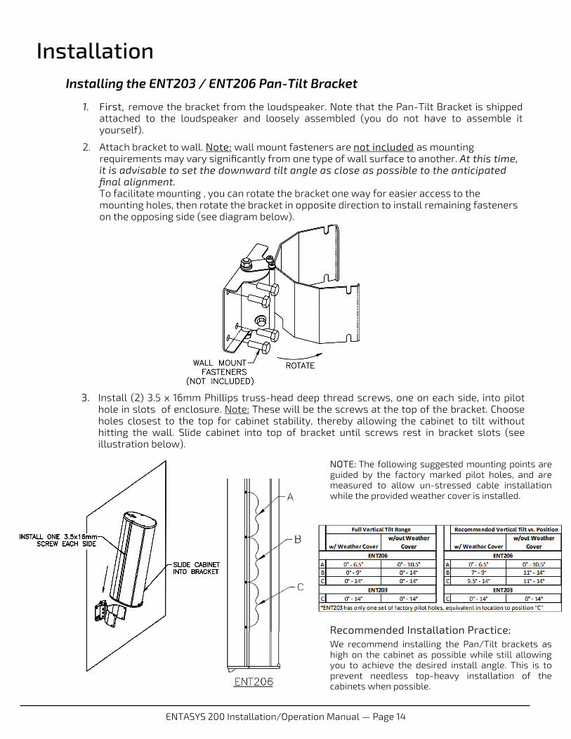
Installation Installing the ENT203 / ENT206 Pan-Tilt Bracket
1. First, remove the bracket from the loudspeaker. Note that the Pan-Tilt Bracket is shipped attached to the loudspeaker and loosely assembled (you do not have to assemble it yourself).
2. Attach bracket to wall. Note: wall mount fasteners are not included as mounting requirements may vary significantly from one type of wall surface to another. At this time, it is advisable to set the downward tilt angle as close as possible to the anticipated final alignment. To facilitate mounting , you can rotate the bracket one way for easier access to the mounting holes, then rotate the bracket in opposite direction to install remaining fasteners on the opposing side (see diagram below).
3. Install (2) 3.5 x 16mm Phillips truss-head deep thread screws, one on each side, into pilot hole in slots of enclosure. Note: These will be the screws at the top of the bracket. Choose holes closest to the top for cabinet stability, thereby allowing the cabinet to tilt without hitting the wall. Slide cabinet into top of bracket until screws rest in bracket slots (see illustration below).
NOTE: The following suggested mounting points are guided by the factory marked pilot holes, and are measured to allow un-stressed cable installation while the provided weather cover is installed.
Recommended Installation Practice: We recommend installing the Pan/Tilt brackets as high on the cabinet as possible while still allowing you to achieve the desired install angle. This is to prevent needless top-heavy installation of the cabinets when possible.
ENTASYS 200 Installation/Operation Manual — Page 15
Installation
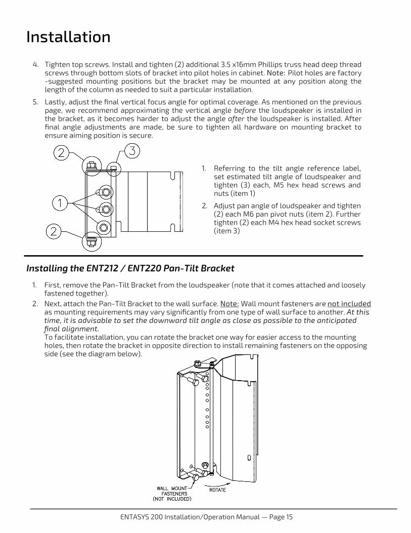
4. Tighten top screws. Install and tighten (2) additional 3.5 x16mm Phillips truss head deep thread screws through bottom slots of bracket into pilot holes in cabinet. Note: Pilot holes are factory-suggested mounting positions but the bracket may be mounted at any position along the length of the column as needed to suit a particular installation.
5. Lastly, adjust the final vertical focus angle for optimal coverage. As mentioned on the previous page, we recommend approximating the vertical angle before the loudspeaker is installed in the bracket, as it becomes harder to adjust the angle after the loudspeaker is installed. After final angle adjustments are made, be sure to tighten all hardware on mounting bracket to ensure aiming position is secure.
Installing the ENT212 / ENT220 Pan-Tilt Bracket
1. First, remove the Pan-Tilt Bracket from the loudspeaker (note that it comes attached and loosely fastened together).
2. Next, attach the Pan-Tilt Bracket to the wall surface. Note: Wall mount fasteners are not included as mounting requirements may vary significantly from one type of wall surface to another. At this time, it is advisable to set the downward tilt angle as close as possible to the anticipated final alignment. To facilitate installation, you can rotate the bracket one way for easier access to the mounting holes, then rotate the bracket in opposite direction to install remaining fasteners on the opposing side (see the diagram below).
1. Referring to the tilt angle reference label, set estimated tilt angle of loudspeaker and tighten (3) each, M5 hex head screws and nuts (item 1)
2. Adjust pan angle of loudspeaker and tighten (2) each M6 pan pivot nuts (item 2). Further tighten (2) each M4 hex head socket screws (item 3)
ENTASYS 200 Installation/Operation Manual — Page 16
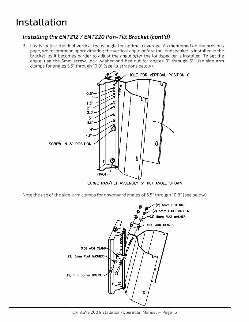
Installation Installing the ENT212 / ENT220 Pan-Tilt Bracket (cont’d)
3. Lastly, adjust the final vertical focus angle for optimal coverage. As mentioned on the previous page, we recommend approximating the vertical angle before the loudspeaker is installed in the bracket, as it becomes harder to adjust the angle after the loudspeaker is installed. To set the angle, use the 5mm screw, lock washer and hex nut for angles 0° through 5°. Use side arm clamps for angles 5.5° through 10.8° (see illustrations below).
Note the use of the side-arm clamps for downward angles of 5.5° through 10.8° (see below).
ENTASYS 200 Installation/Operation Manual — Page 17
Installation
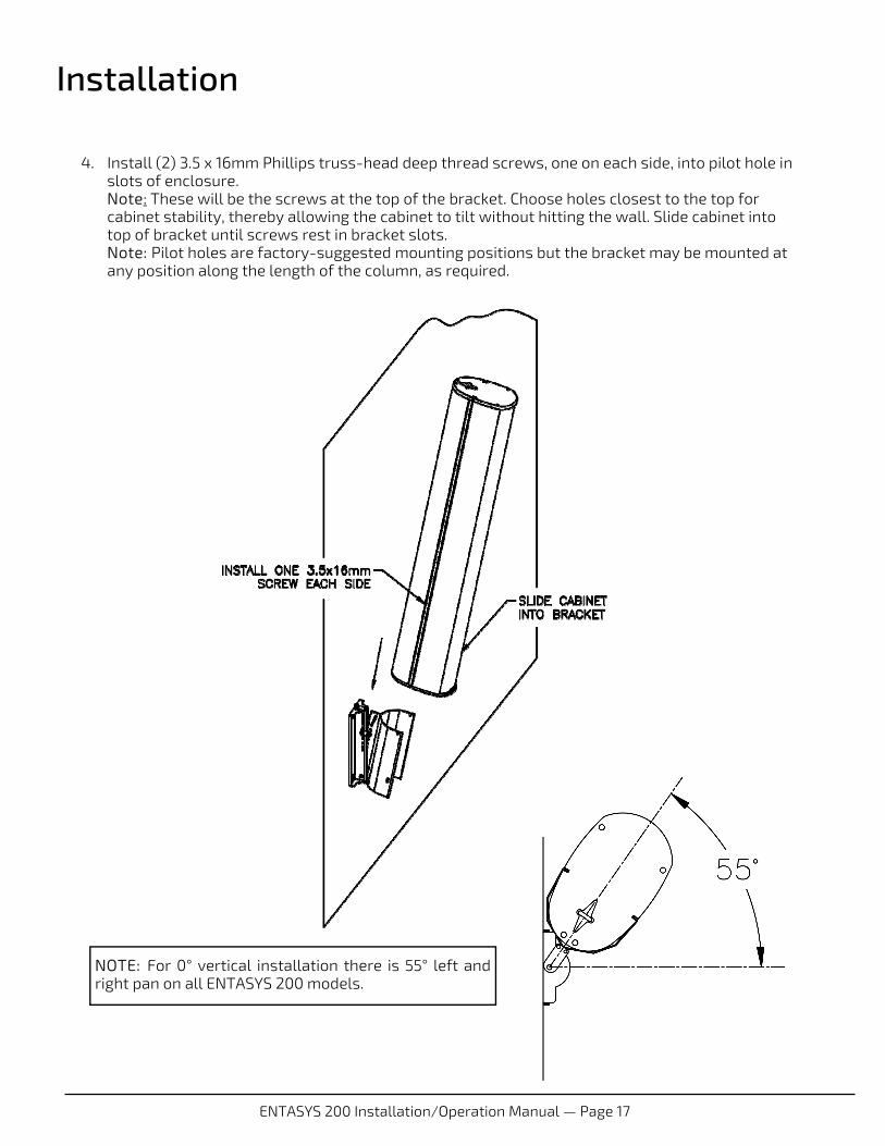
4. Install (2) 3.5 x 16mm Phillips truss-head deep thread screws, one on each side, into pilot hole in slots of enclosure. Note: These will be the screws at the top of the bracket. Choose holes closest to the top for cabinet stability, thereby allowing the cabinet to tilt without hitting the wall. Slide cabinet into top of bracket until screws rest in bracket slots. Note: Pilot holes are factory-suggested mounting positions but the bracket may be mounted at any position along the length of the column, as required.
NOTE: For 0° vertical installation there is 55° left and right pan on all ENTASYS 200 models.
ENTASYS 200 Installation/Operation Manual — Page 18
Installation Installing the ENT212 / ENT220 Pan-Tilt Bracket (cont’d)
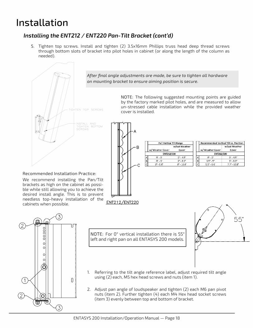
5. Tighten top screws. Install and tighten (2) 3.5x16mm Phillips truss head deep thread screws through bottom slots of bracket into pilot holes in cabinet (or along the length of the column as needed).
NOTE: The following suggested mounting points are guided by the factory marked pilot holes, and are measured to allow un-stressed cable installation while the provided weather cover is installed.
After final angle adjustments are made, be sure to tighten all hardware on mounting bracket to ensure aiming position is secure.
1. Referring to the tilt angle reference label, adjust required tilt angle using (2) each, M5 hex head screws and nuts (item 1).
2. Adjust pan angle of loudspeaker and tighten (2) each M6 pan pivot
nuts (item 2). Further tighten (4) each M4 Hex head socket screws (item 3) evenly between top and bottom of bracket.
Recommended Installation Practice: We recommend installing the Pan/Tilt brackets as high on the cabinet as possi-ble while still allowing you to achieve the desired install angle. This is to prevent needless top-heavy installation of the cabinets when possible.
NOTE: For 0° vertical installation there is 55° left and right pan on all ENTASYS 200 models.
ENTASYS 200 Installation/Operation Manual — Page 19
Installation Using ENTASYS 200 Optional Brackets
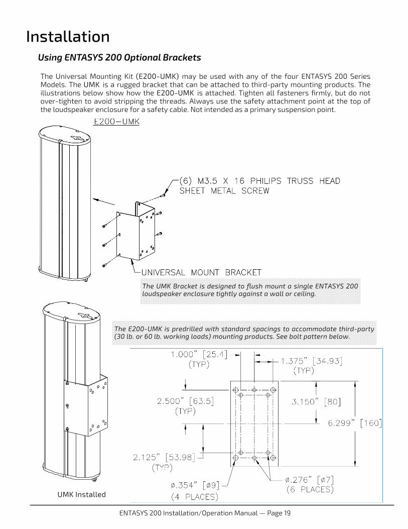
The Universal Mounting Kit (E200-UMK) may be used with any of the four ENTASYS 200 Series Models. The UMK is a rugged bracket that can be attached to third-party mounting products. The illustrations below show how the E200-UMK is attached. Tighten all fasteners firmly, but do not over-tighten to avoid stripping the threads. Always use the safety attachment point at the top of the loudspeaker enclosure for a safety cable. Not intended as a primary suspension point.
UMK Installed
The UMK Bracket is designed to flush mount a single ENTASYS 200 loudspeaker enclosure tightly against a wall or ceiling.
The E200-UMK is predrilled with standard spacings to accommodate third-party (30 lb. or 60 lb. working loads) mounting products. See bolt pattern below.
ENTASYS 200 Installation/Operation Manual — Page 20
Installation
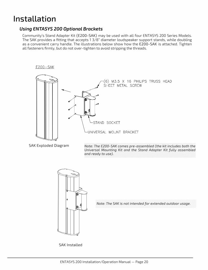
Community’s Stand Adapter Kit (E200-SAK) may be used with all four ENTASYS 200 Series Models. The SAK provides a fitting that accepts 1 3/8” diameter loudspeaker support stands, while doubling as a convenient carry handle. The illustrations below show how the E200-SAK is attached. Tighten all fasteners firmly, but do not over-tighten to avoid stripping the threads.
Using ENTASYS 200 Optional Brackets
Note: The SAK is not intended for extended outdoor usage.
SAK Installed
SAK Exploded Diagram Note: The E200-SAK comes pre-assembled (the kit includes both the Universal Mounting Kit and the Stand Adapter Kit fully assembled and ready to use).
ENTASYS 200 Installation/Operation Manual — Page 21
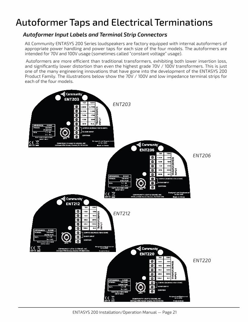
Autoformer Taps and Electrical Terminations Autoformer Input Labels and Terminal Strip Connectors All Community ENTASYS 200 Series loudspeakers are factory equipped with internal autoformers of appropriate power handling and power taps for each size of the four models. The autoformers are intended for 70V and 100V usage (sometimes called “constant voltage” usage).
Autoformers are more efficient than traditional transformers, exhibiting both lower insertion loss, and significantly lower distortion than even the highest grade 70V / 100V transformers. This is just one of the many engineering innovations that have gone into the development of the ENTASYS 200 Product Family. The illustrations below show the 70V / 100V and low impedance terminal strips for each of the four models.
ENT203
ENT206
ENT212
ENT220
ENTASYS 200 Installation/Operation Manual — Page 22
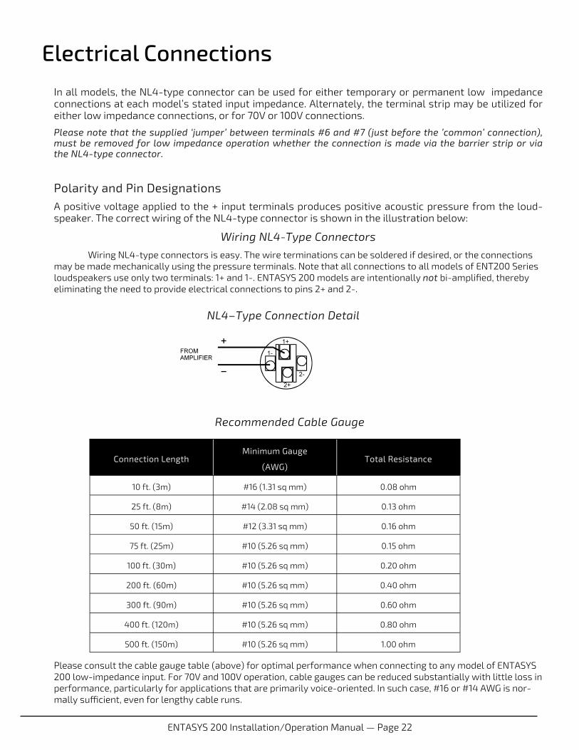
NL4–Type Connection Detail
Electrical Connections In all models, the NL4-type connector can be used for either temporary or permanent low impedance connections at each model’s stated input impedance. Alternately, the terminal strip may be utilized for either low impedance connections, or for 70V or 100V connections.
Please note that the supplied ‘jumper’ between terminals #6 and #7 (just before the ’common’ connection), must be removed for low impedance operation whether the connection is made via the barrier strip or via the NL4-type connector.
Polarity and Pin Designations A positive voltage applied to the + input terminals produces positive acoustic pressure from the loud-speaker. The correct wiring of the NL4-type connector is shown in the illustration below:
Wiring NL4-Type Connectors
Wiring NL4-type connectors is easy. The wire terminations can be soldered if desired, or the connections may be made mechanically using the pressure terminals. Note that all connections to all models of ENT200 Series loudspeakers use only two terminals: 1+ and 1-. ENTASYS 200 models are intentionally not bi-amplified, thereby eliminating the need to provide electrical connections to pins 2+ and 2-.
Please consult the cable gauge table (above) for optimal performance when connecting to any model of ENTASYS 200 low-impedance input. For 70V and 100V operation, cable gauges can be reduced substantially with little loss in performance, particularly for applications that are primarily voice-oriented. In such case, #16 or #14 AWG is nor-mally sufficient, even for lengthy cable runs.
Connection Length Minimum Gauge
(AWG) Total Resistance
10 ft. (3m) #16 (1.31 sq mm) 0.08 ohm
25 ft. (8m) #14 (2.08 sq mm) 0.13 ohm
50 ft. (15m) #12 (3.31 sq mm) 0.16 ohm
75 ft. (25m) #10 (5.26 sq mm) 0.15 ohm
100 ft. (30m) #10 (5.26 sq mm) 0.20 ohm
200 ft. (60m) #10 (5.26 sq mm) 0.40 ohm
300 ft. (90m) #10 (5.26 sq mm) 0.60 ohm
400 ft. (120m) #10 (5.26 sq mm) 0.80 ohm
500 ft. (150m) #10 (5.26 sq mm) 1.00 ohm
Recommended Cable Gauge
ENTASYS 200 Installation/Operation Manual — Page 23
Recommended Amplifier Power
See the guidelines below for recommended low Z amplifier power for each ENTASYS 200 model. Using an amplifier of less power than recommended will not allow maximum performance of the system and may damage the loudspeaker if the amplifier is driven into clipping. Correspondingly, using an amplifier of more power than recommended can result in overdriving the loudspeaker, with the potential for damaging the drivers and/or the protection circuitry.
ENT203: 120W to 180W at 16 ohms
ENT206: 240W to 360W at 8 ohms
ENT212: 520W to 780W at 8 ohms
ENT220: 800W to 1200W at 8 ohms
Connecting Multiple Loudspeakers to a Single Amplifier Channel
The guidelines above are for a single unit of each ENTASYS 200 loudspeaker model. If more than one ENTASYS 200 loudspeaker is connected to the same amplifier channel, the Minimum and Maximum amplifier power ratings should be increased appropriately by multiplying the wattage ratings by the number of loudspeakers connected.
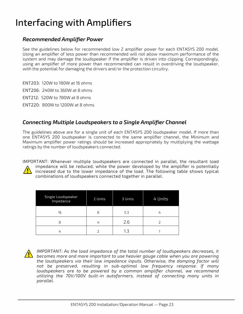
IMPORTANT: Whenever multiple loudspeakers are connected in parallel, the resultant load impedance will be reduced, while the power developed by the amplifier is potentially increased due to the lower impedance of the load. The following table shows typical combinations of loudspeakers connected together in parallel.
IMPORTANT: As the load impedance of the total number of loudspeakers decreases, it becomes more and more important to use heavier gauge cable when you are powering the loudspeakers via their low impedance inputs. Otherwise, the damping factor will not be preserved, resulting in sub-optimal low frequency response. If many loudspeakers are to be powered by a common amplifier channel, we recommend utilizing the 70V/100V built-in autoformers, instead of connecting many units in parallel.
Interfacing with Amplifiers
Single Loudspeaker Impedance
2 Units 3 Units 4 Units
16 8 5.3 4
8 4 2.6 2
4 2 1.3 1
ENTASYS 200 Installation/Operation Manual — Page 24
RIGGING / SUSPENSION AND SAFETY TERMINOLOGY: The terms “rigging”, “flying” and “suspension” are often used interchangeably in describing methods of installing loudspeaker systems at elevated positions.
DANGER: The loudspeakers described in this manual are designed and intended to be suspended using a variety of rigging hardware, means, and methods. It is essential that all installation work involving the suspension of these loudspeaker products be performed by competent, knowledgeable persons who understand safe rigging practices. Severe injury and/or loss of life may occur if these products are improperly suspended.
DANGER: All rigging fittings must be fully tightened and secured. Any missing fasteners will compromise the structural integrity of the enclosure and constitute a safety hazard. Do not suspend this loudspeaker unless all fasteners are securely in place!
COMMUNITY RIGGING HARDWARE WARRANTY: Community warrants that its loudspeaker systems and its optional mounting and rigging hardware have been carefully designed and tested. Community loudspeakers may be safely suspended when each loudspeaker model is suspended with Community-manufactured mounting and rigging brackets specifically designed for use with that particular model of loudspeaker. This warranty applies only for use under normal environmental conditions, and when all loudspeakers, component parts, brackets and hardware are assembled and installed in strict accordance with Community’s installation guidelines contained herein. Beyond this, Community assumes no further or extended responsibility or liability, in any way or by any means whatsoever. It is the responsibility of the installer to insure that safe installation practices are followed, and that such practices are in accordance with any and all local, state, federal, or other, codes, conditions, and regulations that may apply to, or govern the practice of, rigging, mounting, and construction work in the relevant geographic territory. Any modifications made to any parts or materials manufactured or supplied by Community shall immediately void all pledges of warranty or surety, related in any way to the safe use of those parts and materials.
WARNING: USING NON-COMMUNITY RIGGING HARDWARE: Non-Community hardware used for rigging an ENTASYS 200 loudspeaker must be certified by the supplier for this use and must be properly rated for safety.
Important Notes on Rigging Loudspeakers
There are three areas of responsibility for rigging loudspeakers. The first is the building structure. Always consult with the building architect or structural engineer to assure the ability of the structure to support the loudspeaker system. The second area of responsibility is the loudspeaker itself. Community certifies its loudspeaker systems and rigging accessories for suspension when they are properly installed according to our published guidelines. The third area of responsibility is everything between the loudspeaker and the building structure and the actual process of installation. The installing contractor assumes this responsibility. Loudspeaker rigging should be performed only by certified rigging professionals using certified rigging hardware chosen for the specific application. Prior to installation, the contractor should present a rigging plan, with drawings and a detailed parts list, to a licensed structural engineer (P.E.) or architect for written approval.
Acceptable Mounting Point Loading and Working Load Limit
The mounting points should always be used so that either shear force is applied perpendicular to the direction of, and in tight proximity to, the mounting hole or tension force is applied perpendicular to the enclosure surface.
WARNING: ENTASYS 200 rigging hardware is rated only for the applications and number of enclosures as described in this manual or in the instructions supplied with the individual hardware items themselves. Do not exceed these limits. Failure to heed this warning could result in injury or death!
DANGER: Use the mounting points only as described above. Do not use them in such a way as to apply sideways leverage to them. Failure to follow this instruction could result in immediate failure of the mounting points resulting in damage to the loudspeaker and serious injury or death to personnel.
Installation
ENTASYS 200 Installation/Operation Manual — Page 25
Suspending Loudspeakers with Community Brackets
ENTASYS 200 Series loudspeakers can be rigged using a variety of accessories available from Community. We encourage the use of these rigging accessories because they are properly load rated and designed specifically for use with ENTASYS 200 loudspeakers.
GUIDELINES FOR USING ENTASYS 200 OUTDOORS ENTASYS 200 is suitable for outdoor installation and has an IP rating of IP54W when used as recommended herein. For best results in outdoor applications, follow these guidelines:
Tilt the ENTASYS column downwards at least 2° to prevent water accumulation. The included Pan-Tilt Kit may be used for this purpose as described below.
Use the barrier strip input terminals and the supplied weather cover panel. The NL4 type inputs may be used for short-term connections outdoors, but are not recommended for long-term outdoor usage.
Use outdoor-rated cable, such as type SJOW, and route the cable into the ENTASYS column through a 1/2-inch NPT fitting (not supplied). The ENTASYS connector cover panel has a knock-out for this fitting.
The ENTASYS 200 Pan-Tilt Bracket may be used outdoors to provide a small downwards tilt. Do not extend the large Pan-Tilt Bracket with the extension arm as this will increase the possibility of damage in high wind conditions.
Safety cables should always be utilized. Each ENTASYS 200 Model is equipped with a built-in eyebolt on the top of the enclosure for this purpose. The cable should be of adequate size and strength to suspend the loudspeaker in the event of a failure of the mounting bracket, or of the surface to which the mounting bracket is fastened.
Installation in areas that experience frequent dust or sand storms is not recommended. The loudspeaker grille cloth may become clogged, degrading performance.
Winter ice storms may temporarily clog the loudspeaker grille. This will not harm the ENTASYS 200 column, but may degrade performance due to the temporary grille blockage.
Please contact Community’s TAG Team (Technical Applications Group) for additional assistance.
FIELD SERVICE Any driver service required is accessed from the front of the enclosure. Please refer to the section on the following two pages “Painting ENTASYS 200 Loudspeakers” for instructions on how to remove the grille.
The crossovers are not field serviceable. For warranty repair, contact Community directly or ask us for the location of your nearest Authorized Service Center.
Installation

ENTASYS 200 Installation/Operation Manual — Page 26
PAINTING ENTASYS 200 LOUDSPEAKERS
ENTASYS 200 Series may be painted to match room décor if desired. Follow the steps below:
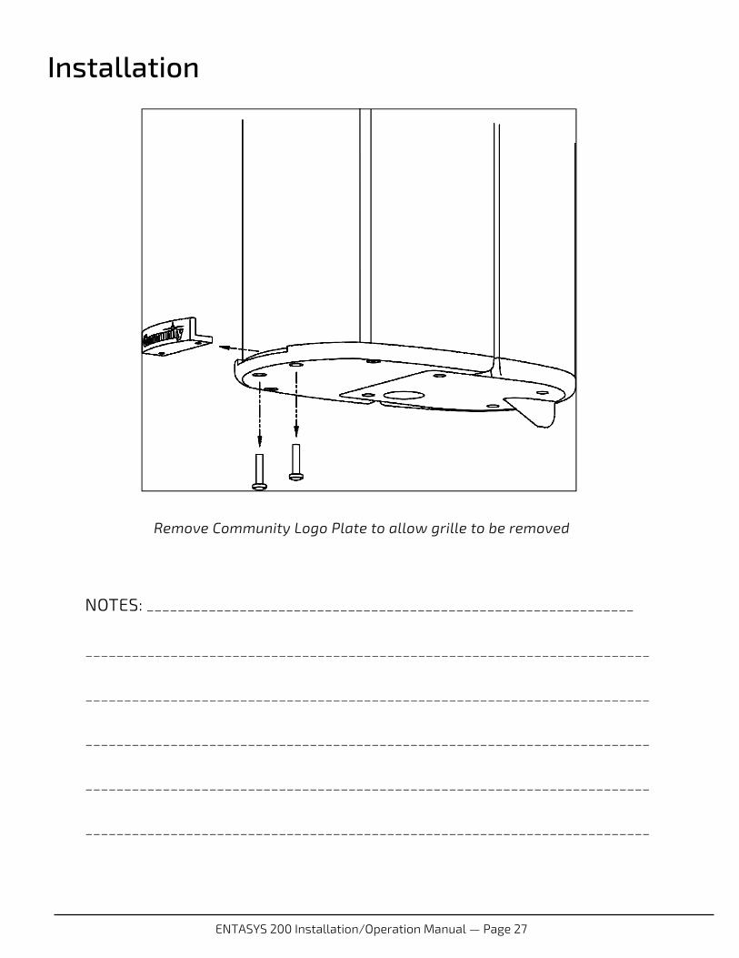
1. First, remove the front grille by removing the two screws that fasten the Community logo to the bottom of the column. Slide the logo out. The grille can then be popped out of the track (refer to the drawing on the opposite page).
2. If the grille is to be painted, first remove the interior acoustic foam before painting the grille. *Note: Do not reapply the existing foam back on the loudspeaker grille. Replacement foam can be purchased from Community (see table below). Foam is supplied in black only.
3. The shell of the column should be thoroughly scuffed using a Scotch-Brite style pad to ensure that the primer and paint will adhere to the slick surface.
4. Mask off all components before applying primer. Make sure to include the weather-resistant cover when prepping and painting the parts. We recommend masking off the bottom label (which has a weep hole for exterior use).
5. Apply a good grade of plastic primer. Such primers are available from paint stores and from the paint department of home improvement centers.
6. Paint the unit with any high-quality paint that is compatible with the primer (check with your paint supplier). For exterior use, choose an exterior-grade paint that is compatible with the primer and will also resist the local climatic conditions (note that darker colors will absorb much more UV from sunlight than lighter colors thereby reducing their lifespan). We recommend painting indoors in a dust-free environment, whenever possible. Always make sure that ventilation is adequate to avoid inhaling toxic fumes.
7. After applying the paint, the replacement grille foam can be re-attached to the interior of the grille with a multipurpose high tack spray adhesive such as 3M Industrial Spray Adhesive. Apply adhesive to grille foam only to prevent clogging of grille perforations.
8. Finally, remove all masking tape and reassemble the grille after the paint has thoroughly dried.
Description Part Number
ENT203 Grille Foam (black) 112190R
ENT206 Grille Foam (black) 112191R
ENT212 Grille Foam (black) 112192R
ENT220 Grille Foam (black) 112193R
*ENTASYS 200 Replacement Grille Foam
Installation
ENTASYS 200 Installation/Operation Manual — Page 27
NOTES: _______________________________________________________________
_________________________________________________________________________
_________________________________________________________________________
_________________________________________________________________________
_________________________________________________________________________
_________________________________________________________________________
Remove Community Logo Plate to allow grille to be removed
Installation

Community Professional Loudspeakers
333 East Fifth Street Chester, PA 19013-4511 USA Tel: 1-(610) 876-3400 FAX: 1-(610) 874-0190
www.communitypro.com
23FEB2016
E SERIES ENTASYS 200
VERSATILE TWO-WAY COLUMN ARRAY SYSTEMS