Embed Size (px)
Citation preview
CanogaView® Smart Element Manager
Enterprise Version i
CanogaView® Smart Element Manager
ii Enterprise Version
NOTICE
Canoga Perkins has prepared this users manual for use by customers and Canoga Perkinspersonnel as a guide for the proper installation, operation and/or maintenance of CanogaPerkins equipment. The drawings, specifications and information contained in this documentare the property of Canoga Perkins and any unauthorized use or disclosure of the drawings,specifications and information is prohibited.
Canoga Perkins reserves the right to change or update the contents of this manual and tochange the specifications of its products at any time without prior notification. Every efforthas been made to keep the information in this document current and accurate as of the dateof publication or revision; however, no guarantee is given or implied that the document iserror free or that it is accurate with regard to any specification.
CANOGA PERKINS CORPORATION20600 Prairie Street
Chatsworth, California 91311-6008Business Phone: (818) 718-6300
(Monday - Friday 7 a.m. - 5 p.m. Pacific Time) FAX: (818) 718-6312 (24 hrs.)Web Site: www.canoga.comEmail: [email protected]
Copyright© 2000, 2003, 2004 Canoga Perkins CorporationAll Rights Reserved
CanogaView Smart Element ManagerEnterprise Version
Part Number 6912640Rev. H 02/2004
SH
To reference Technical Advisories and Product Release Notes, go to Canoga Perkins'website: http://www.canoga.com
CanogaView® Smart Element Manager
Enterprise Version iii
Table of ContentsChapter 1 System Requirements....................................................................................... 11.1 Windows Platform Requirements .............................................................................. 11.1.1 Windows Minimum Hardware Requirements.......................................................... 11.1.2 Windows Minimum Software Requirements ........................................................... 11.2 Solaris Platform Requirements.................................................................................. 11.2.1 Solaris Minimum Hardware Requirements ............................................................. 11.2.2 Solaris Minimum Software Requirements............................................................... 21.3 HP-UX Platform Requirements ................................................................................. 21.3.1 HP-UX Minimum Hardware Requirements ............................................................. 21.3.2 HP-UX Minimum Software Requirements .............................................................. 21.4 SNMP Agent Requirements ...................................................................................... 2Chapter 2 Installing CanogaView Smart Element Manager ............................................. 72.1 Installation Process................................................................................................... 72.2 Installation Steps....................................................................................................... 72.2.1 Insert CD................................................................................................................ 72.2.2 Product Splash Display .......................................................................................... 92.2.3 Installation Introduction ........................................................................................ 102.2.4 License Agreement .............................................................................................. 102.2.5 Important Information ........................................................................................... 122.2.6 Choose Install Folder ........................................................................................... 132.2.7 Choose Shortcut Location .................................................................................... 132.2.8 Choose Link Location........................................................................................... 142.2.9 Select Install Set .................................................................................................. 152.2.10 Enter SNMP Trap Port ......................................................................................... 162.2.11 Enter CanogaView Server Host............................................................................ 172.2.12 NNM Integration................................................................................................... 192.2.13 Pre-Installation Summary ..................................................................................... 192.2.14 Installation Billboards ........................................................................................... 212.2.17 Installation Complete............................................................................................ 222.3 Post Installation Steps............................................................................................. 222.3.1 HP OpenView URL Setup for SNMP Agents ........................................................ 222.3.2 Netscape Navigator Environment Variable (Unix only) ......................................... 242.3.3 Delete Directories if Desired (Unix only) ............................................................... 24Chapter 3 Using CanogaView Smart Element Manager................................................. 253.1 User Interface Overview.......................................................................................... 253.1.1 Application Overview............................................................................................ 253.1.2 Menus and Toolbars ............................................................................................ 293.1.3 License Restrictions ............................................................................................. 303.2 Getting Started........................................................................................................ 323.2.1 Opening CanogaView Smart Element Manager ................................................... 323.2.2 Start CanogaView Smart Element Manager ......................................................... 333.2.3 Login.................................................................................................................... 353.2.4 Agent Chooser ..................................................................................................... 353.2.5 Views ................................................................................................................... 383.3 Other Applications................................................................................................... 443.3.1 Account Manager................................................................................................. 443.3.2 Alarm Monitor....................................................................................................... 463.3.3 Configuration........................................................................................................ 51
CanogaView® Smart Element Manager
iv Enterprise Version
3.3.4 Reset ................................................................................................................... 523.3.5 Reports ................................................................................................................ 543.3.6 Security Manager................................................................................................. 583.3.7 Status .................................................................................................................. 603.3.8 Telnet .................................................................................................................. 643.3.9 TFTP Server ........................................................................................................ 65Chapter 4 Frequently Asked Questions.......................................................................... 674.1 What Web Server Platforms are supported?........................................................... 674.2 What Web Client Platforms are supported? ............................................................ 674.3 What Web Server is used by CanogaView Smart Element Manager? .................... 674.4 What is a Java Plug-In or Java Runtime Environment?........................................... 674.5 How many Web Clients are supported?.................................................................. 674.6 How many User Accounts are supported?.............................................................. 684.7 How do I Install CanogaView Smart Element Manager? ......................................... 684.8 How do I Uninstall CanogaView Smart Element Manager?..................................... 684.9 How do I Login?...................................................................................................... 684.10 Why doesn't CanogaView Smart Element Manager support Netscape 6.0? ........... 684.11 What Version of HP OpenView can CanogaView Smart Element Manager beintegrated with?.................................................................................................................. 694.12 What does CanogaView Smart Element Manager actually do? .............................. 694.13 Which Canoga Perkin's Products does CanogaView Smart Element Managermanage? ............................................................................................................................ 694.14 What versions of the products must be installed? ................................................... 694.15 What is a Domain? ................................................................................................. 694.16 How are Remote Products managed? .................................................................... 704.17 What Security Levels does CanogaView Smart Element Manager support?........... 70Chapter 5 Troubleshooting.............................................................................................. 715.1 No Response from SNMP Agent ............................................................................ 715.2 "Model Not Found" image appears on my View ...................................................... 715.3 Traps/Alarm Processing.......................................................................................... 72
CanogaView® Smart Element Manager
Enterprise Version v
List of FiguresFigure 1-1: DMM Host Table............................................................................................... 3Figure 1-2: 9135 Host Table ............................................................................................... 4Figure 1-3: SNMP Agent Chooser showing Edit Window ................................................ 5Figure 2-1: Product Splash Display................................................................................... 9Figure 2-2: Installation Introduction................................................................................ 10Figure 2-3: License Agreement ....................................................................................... 11Figure 2-4: Important Information ................................................................................... 12Figure 2-5: Choose Install Folder .................................................................................... 13Figure 2-6. Choose Shortcut Location ............................................................................ 14Figure 2-7. Choose Link Location. ................................................................................. 15Figure 2-8. Choose Install Set......................................................................................... 16Figure 2-9: Enter SNMP Trap Port .................................................................................. 17Figure 2-10: Enter Web Server HTTP Port ..................................................................... 18Figure 2-11: NNM Integration.......................................................................................... 19Figure 2-12: Pre-Installation Summary .......................................................................... 20Figure 2-13: Billboard Example ....................................................................................... 21Figure 2-14: Installation Complete .................................................................................. 22Figure 3-1. Starting Point ................................................................................................. 25Figure 3-2. Agent Chooser Toolbar ................................................................................. 29Figure 3-3. Domain View Toolbar .................................................................................... 29Figure 3-4. Device View Toolbar ...................................................................................... 29Figure 3-5. Too many users ............................................................................................. 31Figure 3-6. Shortcut Menu ............................................................................................... 32Figure 3-7. IE Address Field Example ............................................................................. 33Figure 3-8. CanogaView Start Page................................................................................. 34Figure 3-9. Login Screen.................................................................................................. 35Figure 3-10: SNMP Agent Chooser.................................................................................. 36Figure 3-11. Add/Edit Agent Screen ................................................................................ 37Figure 3-12. Agent Chooser Status Example.................................................................. 38Figure 3-13. Selectable Views.......................................................................................... 39Figure 3-14. Domain View. ............................................................................................... 40Figure 3-15. Chassis View................................................................................................ 41Figure 3-16. Modem View. ................................................................................................ 42Figure 3-17. 9135G View................................................................................................... 43Figure 3-18. 9135G Port View........................................................................................... 43Figure 3-19: Account Manager ........................................................................................ 45Figure 3-20: Add User ...................................................................................................... 45Figure 3-21. Alarm Monitor – All Alarms Filter ............................................................... 47Figure 3-23. Alarm Legend............................................................................................... 49Figure 3-24. Alarm Event Queries ................................................................................... 50
CanogaView® Smart Element Manager
vi Enterprise Version
Figure 3-25. Alarms Records by Log Time Input............................................................ 50Figure 3-26. Example Alarm Report ................................................................................ 51Figure 3-27. 9135G Port Configuration ........................................................................... 52Figure 3-28. Fiber Optic Modem Reset Example ............................................................ 53Figure 3-29. 9135G Reset Example ................................................................................. 53Figure 3-30. Factory Defaults Confirmation Example .................................................... 54Figure 3-31. Reset Confirmation Example ...................................................................... 54Figure 3-32. Domain Level Reports................................................................................. 55Figure 3-33. Domain Level Report Example ................................................................... 56Figure 3-34. 9135G Report ............................................................................................... 57Figure 3-35. Security Manager......................................................................................... 59Figure 3-36. Chassis Status............................................................................................. 60Figure 3-37. 9135G Status – General Tab ....................................................................... 61Figure 3-38. 9135G Status – Spanning Tree Tab ............................................................ 62Figure 3-39. 9135G Status – Forwarding Database Tab................................................. 63Figure 3-40. 9135G Status – Version Tab ....................................................................... 63Figure 3-41. 9135G Port Statistics................................................................................... 64Figure 3-42. DMM Telnet Example................................................................................... 65Figure 3-43. TFTP Server Utility ...................................................................................... 66Figure 3-44. TFTP Help..................................................................................................... 66

CanogaView® Smart Element Manager
Enterprise Version 1
Chapter 1 System Requirem entsThe CanogaView Smart Element Manager Server’s hardware and software minimumrequirements as well as the SNMP Agent requirements are listed in this section of themanual. CanogaView Smart Element Manager installation support exists for Windows,Solaris and HP-UX platforms.
The Enterprise Version of CanogaView Smart Element Manager is installed with a restrictedone (1) seat license which limits its use to only one active login session at a time. Upgradeoptions for ten (10) seat and unlimited seat licensing are available.
1.1 Windows Platform Requirements1.1.1 Windows Minimum Hardware Requirements
• Intel Pentium 500MHz Processor (1GHz or higher is strongly recommended)• 128MB RAM (256MB or higher is strongly recommended)• 200MB free disk space for application space• 300MB free disk space of tmp space during the installation process• SVGA Monitor with 256 colors and 1024x768 resolution will display but the quality
will be extremely poor. It is strongly recommended that 65536 colors (16 bit) orhigher be used.
• Network Adapter Card is required for Ethernet LAN support
1.1.2 Windows Minimum Software Requirements• Microsoft Windows OS with TCP/IP Services:
• Windows NT 4.0 SP4 -or-• Windows 2000 -or-• Windows XP
• Web Browser supporting Java Plug-In:• Netscape Navigator 4.06 or later –or-• Microsoft Internet Explorer 4.0 or later
• Java Plug-In 1.3.0_01 or later• HP OpenView Network Node Manager 6.1 (optional)
1.2 Solaris Platform Requirements1.2.1 Solaris Minimum Hardware Requirements
• Sun SparcStation• 128MB RAM (256MB is recommended)• 200MB free disk space for application space• 300MB free disk space of tmp space during the installation process• CD-ROM Drive
CanogaView® Smart Element Manager
2 Enterprise Version
1.2.2 Solaris Minimum Software Requirements• Sun Solaris OS Version 7 (a.k.a. Solaris 2.7, SunOS 5.7)• Web Browser supporting Java Plug-In:
• Netscape Navigator 4.76 or later• Java plug-In 1.3.0_01 or later• HP OpenView Network Node Manager 6.1 (optional)
1.3 HP-UX Platform Requirements1.3.1 HP-UX Minimum Hardware Requirements
• HP 9000 workstation, Series 700 or 800• 128MB RAM (256MB is recommended)• 200MB free disk space for application space• 300MB free disk space of tmp space during the installation process• CD-ROM Drive
1.3.2 HP-UX Minimum Software Requirements• HP-UX version 11.0• Web Browser supporting Java Plug-In:
• Netscape Navigator 4.75• Java plug-In 1.3.0• HP OpenView Network Node Manager 6.1 (optional)
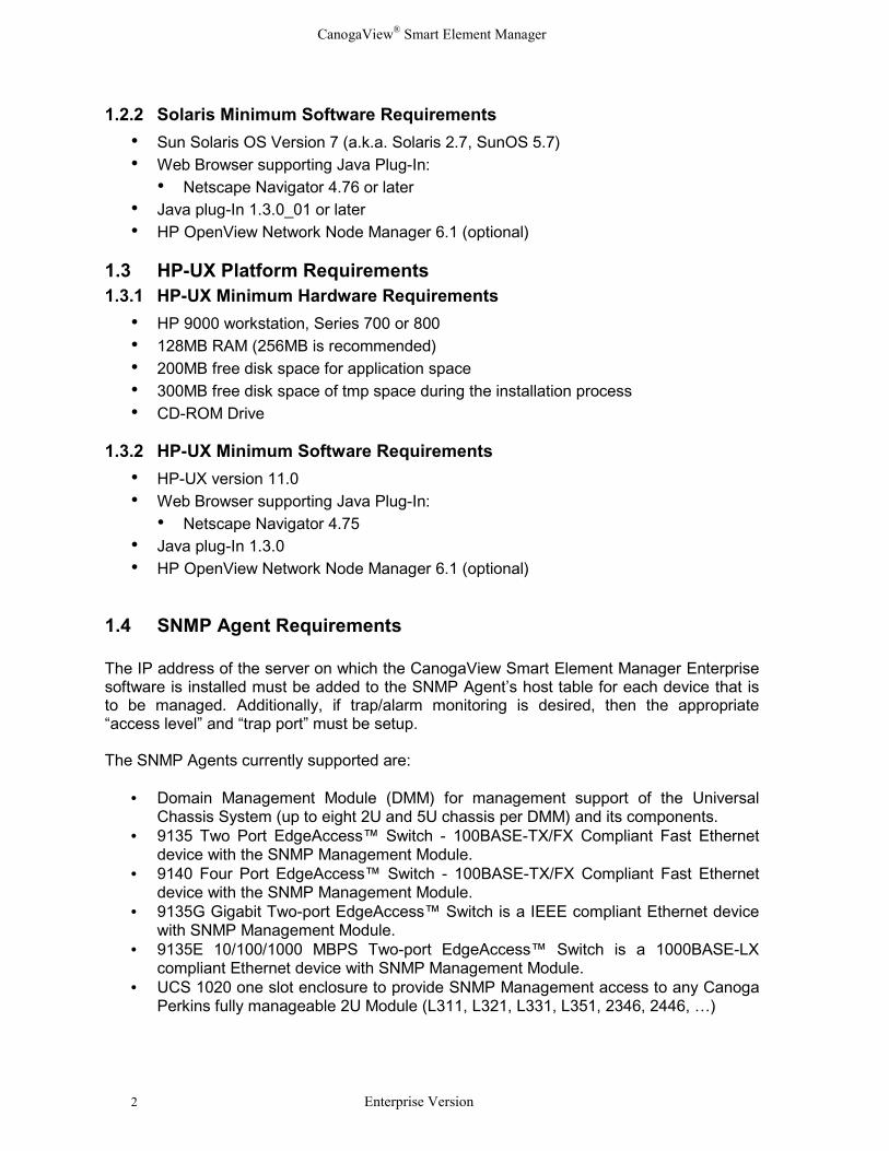
1.4 SNMP Agent Requirements
The IP address of the server on which the CanogaView Smart Element Manager Enterprisesoftware is installed must be added to the SNMP Agent’s host table for each device that isto be managed. Additionally, if trap/alarm monitoring is desired, then the appropriate“access level” and “trap port” must be setup.
The SNMP Agents currently supported are:
• Domain Management Module (DMM) for management support of the UniversalChassis System (up to eight 2U and 5U chassis per DMM) and its components.
• 9135 Two Port EdgeAccess™ Switch - 100BASE-TX/FX Compliant Fast Ethernetdevice with the SNMP Management Module.
• 9140 Four Port EdgeAccess™ Switch - 100BASE-TX/FX Compliant Fast Ethernetdevice with the SNMP Management Module.
• 9135G Gigabit Two-port EdgeAccess™ Switch is a IEEE compliant Ethernet devicewith SNMP Management Module.
• 9135E 10/100/1000 MBPS Two-port EdgeAccess™ Switch is a 1000BASE-LXcompliant Ethernet device with SNMP Management Module.
• UCS 1020 one slot enclosure to provide SNMP Management access to any CanogaPerkins fully manageable 2U Module (L311, L321, L331, L351, 2346, 2446, …)
CanogaView® Smart Element Manager
Enterprise Version 3
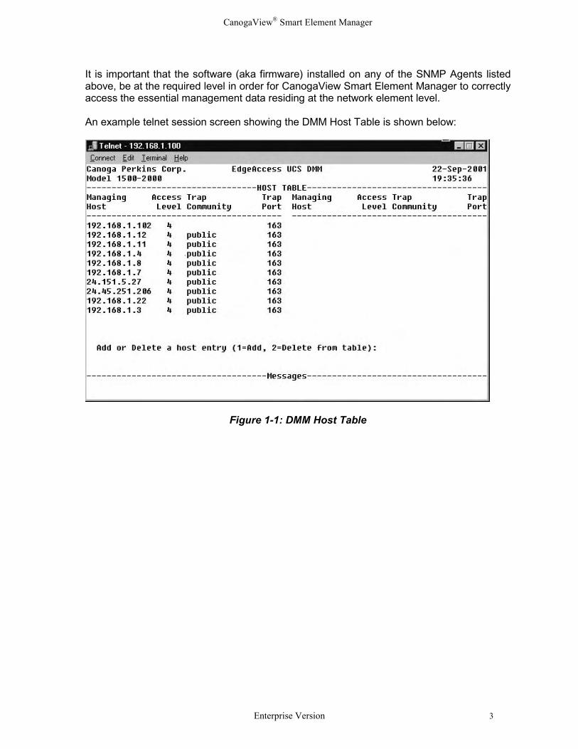
It is important that the software (aka firmware) installed on any of the SNMP Agents listedabove, be at the required level in order for CanogaView Smart Element Manager to correctlyaccess the essential management data residing at the network element level.
An example telnet session screen showing the DMM Host Table is shown below:
Figure 1-1: DMM Host Table
CanogaView® Smart Element Manager
4 Enterprise Version
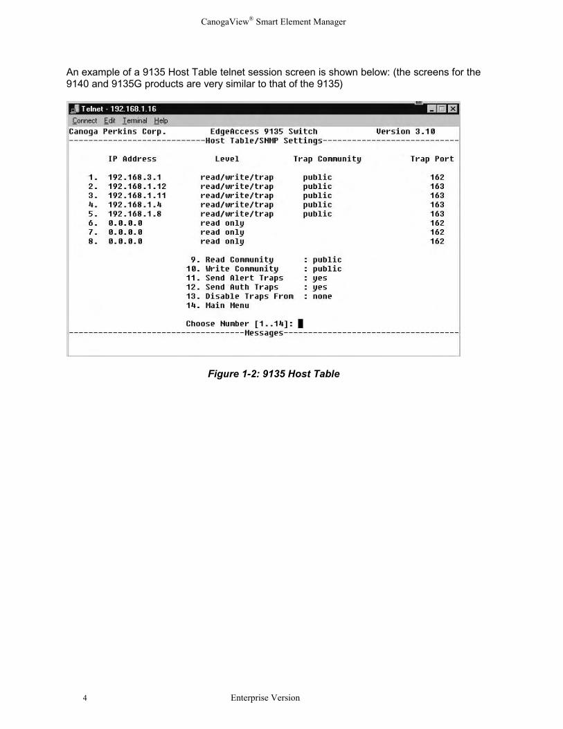
An example of a 9135 Host Table telnet session screen is shown below: (the screens for the9140 and 9135G products are very similar to that of the 9135)
Figure 1-2: 9135 Host Table
CanogaView® Smart Element Manager
Enterprise Version 5
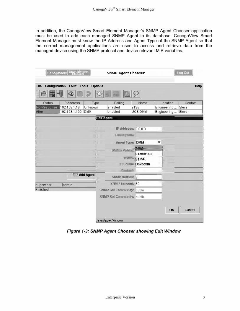
In addition, the CanogaView Smart Element Manager’s SNMP Agent Chooser applicationmust be used to add each managed SNMP Agent to its database. CanogaView SmartElement Manager must know the IP Address and Agent Type of the SNMP Agent so thatthe correct management applications are used to access and retrieve data from themanaged device using the SNMP protocol and device relevant MIB variables.
Figure 1-3: SNMP Agent Chooser showing Edit Window

CanogaView® Smart Element Manager
6 Enterprise Version
CanogaView® Smart Element Manager
Enterprise Version 7
Chapter 2 Installing CanogaView Smart Element ManagerAll files necessary for the installation of the CanogaView Smart Element Manager softwareare contained on the installation CD. Additionally, this manual as well as other technicalinformation is also contained on the CD and installed with the software.
2.1 Installation ProcessThe following steps assume that the CanogaView Smart Element Manager software is beinginstalled via the installation CD. If the software has been downloaded from Canoga Perkin’scorporate web site, then locate the “install.htm” file at the top of the downloaded directorytree and select/execute it.
If you install CanogaView onto a computer running Network Node Manager (NNM) and youselect the option to integrate with NNM, the NNM services must be running. Additionally, ifthe NNM user interface is running, ensure that the Event Configuration application is notdisplayed. You will be reminded of this during the installation.
Note: The actual install process will vary slightly depending upon the hardwareplatform, operating system software and the response to installer prompts. Not all ofthe installer steps described appear during installation. The installation screenexamples shown in this manual are from a Windows NT installation with HPOpenView NNM also installed.
2.2 Installation Steps
2.2.1 Insert CD
Windows Platforms
Insert the CD into the CD-ROM drive.
If the installer web page did not automatically display when the CD was inserted intothe CD-ROM drive, locate the file install.htm and double click on it or open it withyour browser (File >> Open or File >> Open Page). Read the installationinstructions and then proceed to the next step.
The next step in the installation process is basically to locate and execute theinstallation procedure which is on the CD. This can be done by selecting (clicking) onthis install link, or by locating the InstData/Windows/Vm directory on the CD ROMand executing the file install.exe.
Next proceed to section 2.2.2.
CanogaView® Smart Element Manager
8 Enterprise Version
Solaris Platform
Insert the CD into the CD-ROM drive.
Mount the CD via the command:
cd /cdrom/cdrom0
If this command fails, wait a few moments and try again (it may take a short time forthe CD-ROM to be detected).
Locate the file install.htm and open it with your browser (File >> Open Page). Abrowser page will open with the CanogaView Smart Element Manager imagedisplayed. Read the installation instructions and proceed to the next step.
The next in the installation process is basically to locate and execute the installationprocedure which is on the CD. Locate the InstData/Solaris/Vm directory on the CDROM and executing the file install.bin.
Next proceed to section 2.2.2.
HP-UX Platform
Installation on HP-UX requires that the Portable File System (PFS) processespfs_mountd and pfsd be running. Determine if they are running by executing thecommand:
ps -e | grep pfs
If this command returns no output, start the PFS processes via these commands:
nohup /usr/sbin/pfs_mountd &nohup /usr/sbin/pfsd &
Insert the CD into the CD-ROM drive. If the directory /cdrom does not exist on yourworkstation, create it now:
mkdir /cdrom
Mount the CD via the command:
/usr/sbin/pfs_mount -t rrip /dev/rdsk/c0t0d0 /cdrom
Substitute the device name of your CD-ROM drive for /dev/rdsk/c0t0d0 if necessary(command “ioscan -fnC disk” will display your CD-ROM device name).
CanogaView® Smart Element Manager
Enterprise Version 9
Make sure that Netscape Navigator recognizes the “.bin” file extension as a binaryexecutable file.
Display the Navigator Preferences window (Edit >> Preferences). Open thepreferences for category Navigator >> Applications, and find the “Binary Executable”list item. Select this item and click Edit. If “bin” is not listed in the Suffixes field,append it to the current value of Suffixes and save the change (use a comma toseparate suffix values (e.g. “uu,bin”)).
Locate the file install.htm and open it with your browser (File >> Open Page). Abrowser page will open with the CanogaView Smart Element Manager imagedisplayed. Read the installation instructions and then proceed to the next step.
The next in the installation process is basically to locate and execute the installationprocedure which is on the CD. Locate the InstData/Hpux/Vm directory on the CDROM and executing the file install.bin. Proceed to section 2.2.2 below.
2.2.2 Product Splash Display
Once extracted, the installation process will display the CanogaView Smart ElementManager product splash window that follows:
Figure 2-1: Product Splash Display
CanogaView® Smart Element Manager
10 Enterprise Version
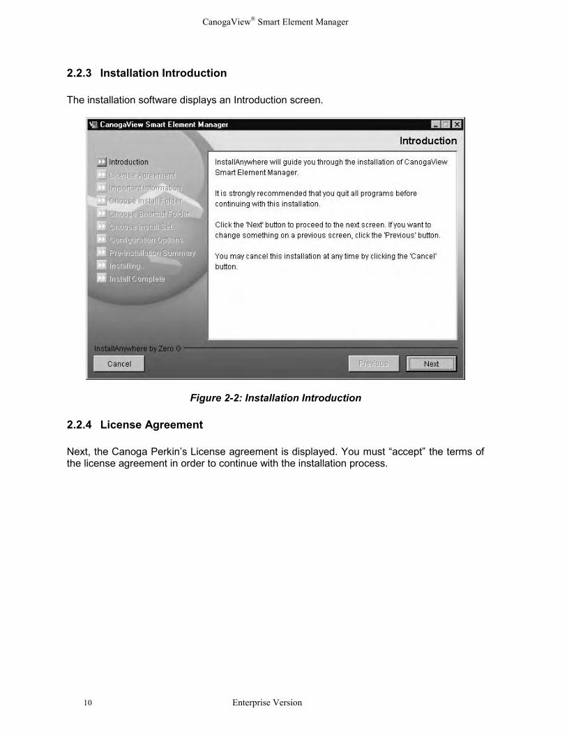
2.2.3 Installation Introduction
The installation software displays an Introduction screen.
Figure 2-2: Installation Introduction
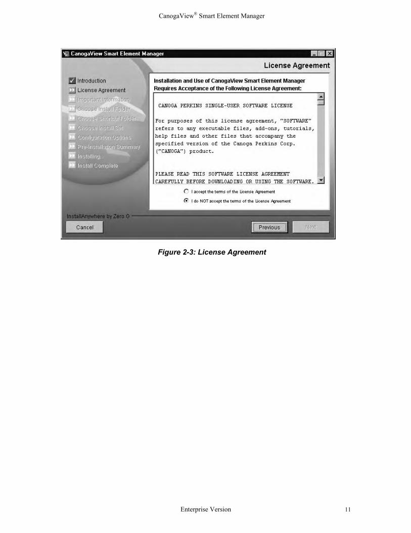
2.2.4 License Agreement
Next, the Canoga Perkin’s License agreement is displayed. You must “accept” the terms ofthe license agreement in order to continue with the installation process.
CanogaView® Smart Element Manager
Enterprise Version 11
Figure 2-3: License Agreement
CanogaView® Smart Element Manager
12 Enterprise Version
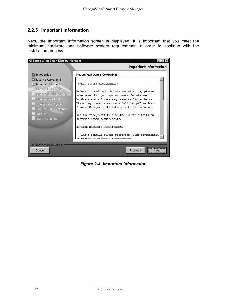
2.2.5 Important Information
Next, the Important Information screen is displayed. It is important that you meet theminimum hardware and software system requirements in order to continue with theinstallation process.
Figure 2-4: Important Information
CanogaView® Smart Element Manager
Enterprise Version 13
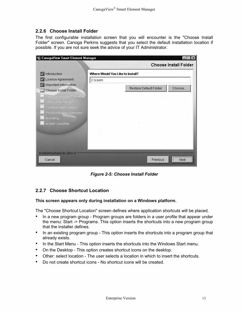
2.2.6 Choose Install FolderThe first configurable installation screen that you will encounter is the "Choose InstallFolder" screen. Canoga Perkins suggests that you select the default installation location ifpossible. If you are not sure seek the advice of your IT Administrator.
Figure 2-5: Choose Install Folder
2.2.7 Choose Shortcut Location
This screen appears only during installation on a Windows platform.
The "Choose Shortcut Location" screen defines where application shortcuts will be placed. • In a new program group - Program groups are folders in a user profile that appear under
the menu: Start -> Programs. This option inserts the shortcuts into a new program groupthat the installer defines.
• In an existing program group - This option inserts the shortcuts into a program group thatalready exists.
• In the Start Menu - This option inserts the shortcuts into the Windows Start menu.• On the Desktop - This option creates shortcut icons on the desktop.• Other: select location - The user selects a location in which to insert the shortcuts.• Do not create shortcut icons - No shortcut icons will be created.
CanogaView® Smart Element Manager
14 Enterprise Version
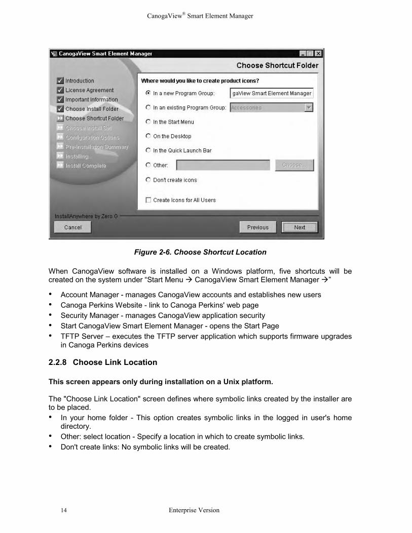
Figure 2-6. Choose Shortcut Location
When CanogaView software is installed on a Windows platform, five shortcuts will becreated on the system under “Start Menu � CanogaView Smart Element Manager �”
• Account Manager - manages CanogaView accounts and establishes new users• Canoga Perkins Website - link to Canoga Perkins' web page• Security Manager - manages CanogaView application security• Start CanogaView Smart Element Manager - opens the Start Page• TFTP Server – executes the TFTP server application which supports firmware upgrades
in Canoga Perkins devices
2.2.8 Choose Link Location
This screen appears only during installation on a Unix platform.
The "Choose Link Location" screen defines where symbolic links created by the installer areto be placed.• In your home folder - This option creates symbolic links in the logged in user's home
directory.• Other: select location - Specify a location in which to create symbolic links.• Don't create links: No symbolic links will be created.
CanogaView® Smart Element Manager
Enterprise Version 15
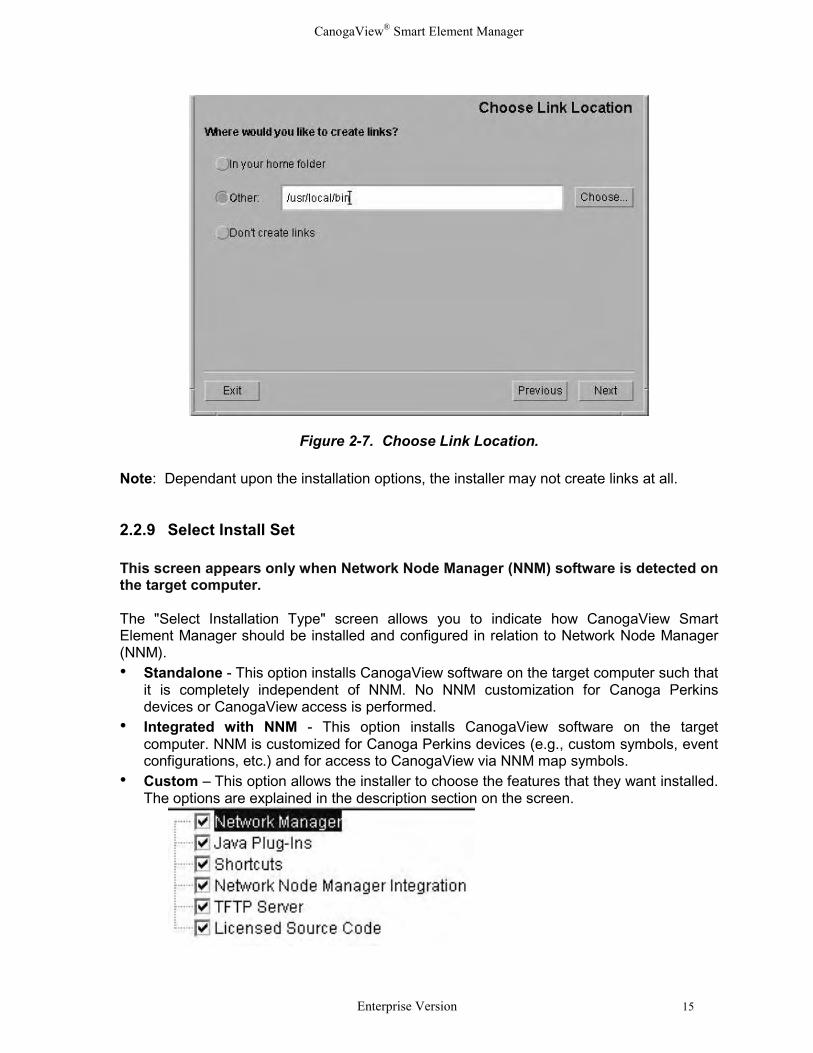
Figure 2-7. Choose Link Location.
Note: Dependant upon the installation options, the installer may not create links at all.
2.2.9 Select Install Set
This screen appears only when Network Node Manager (NNM) software is detected onthe target computer.
The "Select Installation Type" screen allows you to indicate how CanogaView SmartElement Manager should be installed and configured in relation to Network Node Manager(NNM).• Standalone - This option installs CanogaView software on the target computer such that
it is completely independent of NNM. No NNM customization for Canoga Perkinsdevices or CanogaView access is performed.
• Integrated with NNM - This option installs CanogaView software on the targetcomputer. NNM is customized for Canoga Perkins devices (e.g., custom symbols, eventconfigurations, etc.) and for access to CanogaView via NNM map symbols.
• Custom – This option allows the installer to choose the features that they want installed.The options are explained in the description section on the screen.
CanogaView® Smart Element Manager
16 Enterprise Version
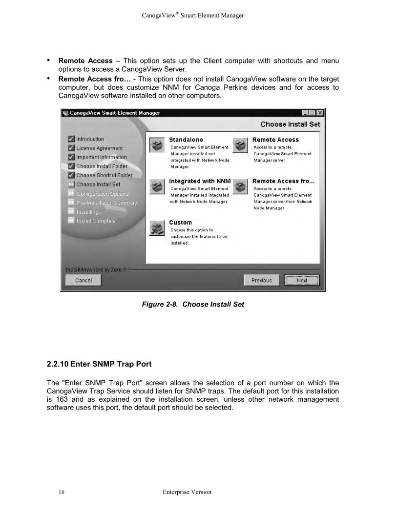
• Remote Access – This option sets up the Client computer with shortcuts and menuoptions to access a CanogaView Server.
• Remote Access fro… - This option does not install CanogaView software on the targetcomputer, but does customize NNM for Canoga Perkins devices and for access toCanogaView software installed on other computers.
Figure 2-8. Choose Install Set
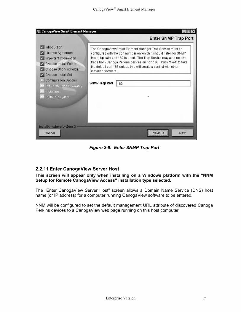
2.2.10 Enter SNMP Trap Port
The "Enter SNMP Trap Port" screen allows the selection of a port number on which theCanogaView Trap Service should listen for SNMP traps. The default port for this installationis 163 and as explained on the installation screen, unless other network managementsoftware uses this port, the default port should be selected.
CanogaView® Smart Element Manager
Enterprise Version 17
Figure 2-9: Enter SNMP Trap Port
2.2.11 Enter CanogaView Server HostThis screen will appear only when installing on a Windows platform with the "NNMSetup for Remote CanogaView Access" installation type selected.
The "Enter CanogaView Server Host" screen allows a Domain Name Service (DNS) hostname (or IP address) for a computer running CanogaView software to be entered.
NNM will be configured to set the default management URL attribute of discovered CanogaPerkins devices to a CanogaView web page running on this host computer.
CanogaView® Smart Element Manager
18 Enterprise Version
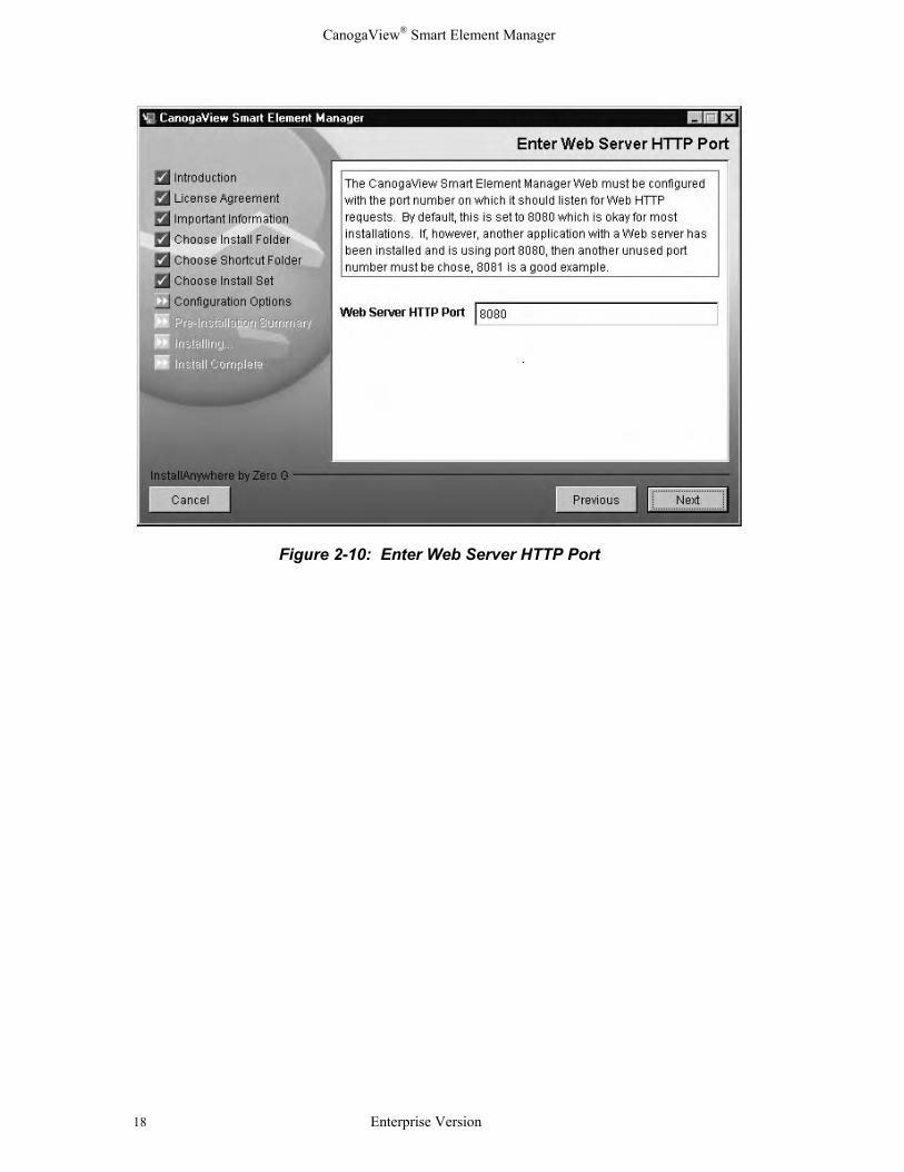
Figure 2-10: Enter Web Server HTTP Port
CanogaView® Smart Element Manager
Enterprise Version 19
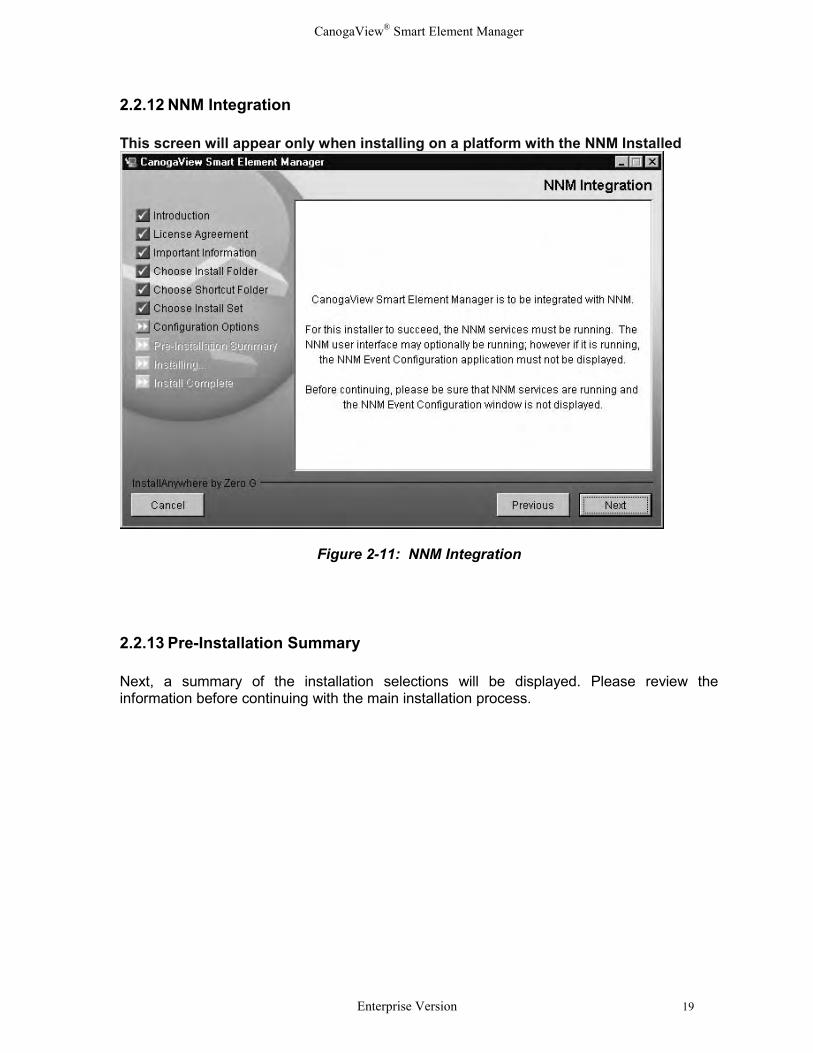
2.2.12 NNM Integration
This screen will appear only when installing on a platform with the NNM Installed
Figure 2-11: NNM Integration
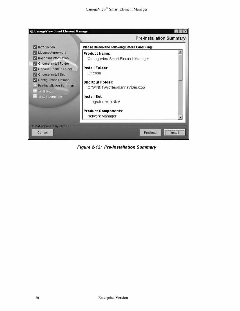
2.2.13 Pre-Installation Summary
Next, a summary of the installation selections will be displayed. Please review theinformation before continuing with the main installation process.
CanogaView® Smart Element Manager
20 Enterprise Version
Figure 2-12: Pre-Installation Summary
CanogaView® Smart Element Manager
Enterprise Version 21
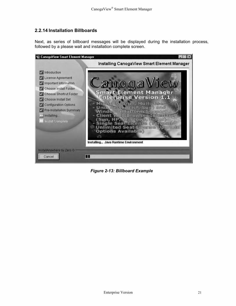
2.2.14 Installation Billboards
Next, as series of billboard messages will be displayed during the installation process,followed by a please wait and installation complete screen.
Figure 2-13: Billboard Example
CanogaView® Smart Element Manager
22 Enterprise Version
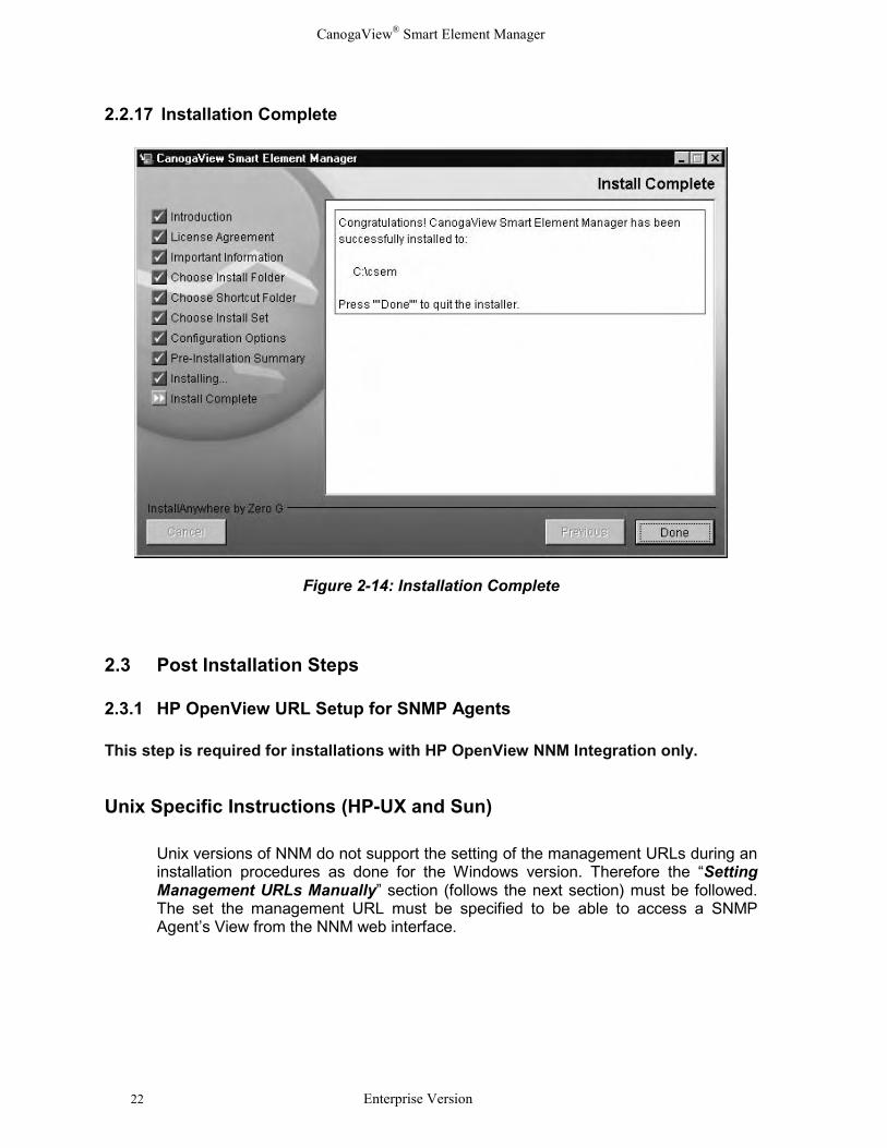
2.2.17 Installation Complete
Figure 2-14: Installation Complete
2.3 Post Installation Steps
2.3.1 HP OpenView URL Setup for SNMP Agents
This step is required for installations with HP OpenView NNM Integration only.
Unix Specific Instructions (HP-UX and Sun)
Unix versions of NNM do not support the setting of the management URLs during aninstallation procedures as done for the Windows version. Therefore the “SettingManagement URLs Manually” section (follows the next section) must be followed.The set the management URL must be specified to be able to access a SNMPAgent’s View from the NNM web interface.
CanogaView® Smart Element Manager
Enterprise Version 23
Windows Specific Instructions
When integrating with HP’s Windows version of NNM, CanogaView Smart ElementManager configures NNM to set the Management URL attribute for the CanogaPerkins’ SNMP managed devices; DMM for 2U and 5U chassis based products,9135 related devices and any of the managed devices residing in a standalonedevice (eg. 1020, 1040, etc.). If for any reason this setting is unsuccessful, themanual setting of such is required. The setting of the management URL must bespecified to be able to access an SNMP Agent’s View from the NNM web interface.
If a SNMP Agent's Management URL attribute does not get set properly, tryadjusting the NNM configuration change polling interval. This interval is accessedvia the NNM dialog: Options->Network Polling Configuration:IP/IPX
Make sure "Perform configuration checks" is checked. The value for "Configurationpolling interval" is the maximum length of time it should take for NNM to set theManagement URL for SNMP Agent(s) after installing CanogaView Smart ElementManager. Since the default interval is one day, you may want to adjust this to ashorter interval, at least temporarily. Note that these two parameters are also usedby the NNM netmon process.
If the Management URL still does not get set properly, it may be configured manuallyas documented below.
Setting Management URLs Manually
1. Select a DMM, 9135/40 or 9135G symbol on a NNM submap.2. Select "Object Properties" on the Edit menu.3. Double-click on "General Attributes".4. Set attribute "isHTTPManaged" to "True".5. Set attribute "ManagementURL" to one of the following depending on the SNMP Agent
type:
DMM "http://nms_server_host:8080/nms/jsp/DomainView.jsp?IP_CONTEXT=agent_ip_addr"
9135 "http://nms_server_host:8080/nms/jsp/Dev91xxView.jsp?IP_CONTEXT=agent_ip_addr"
9135G "http://nms_server_host:8080/nms/jsp/Dev91xxgView.jsp?IP_CONTEXT=agent_ip_addr"
9140 "http://nms_server_host:8080/nms/jsp/Dev91xxView.jsp?IP_CONTEXT=agent_ip_addr"
Notes: 1. These are case sensitive.2. Replace "nms_server_host" with the hostname or IP address of the server on which you
installed the CanogaView Smart Element Manager software. 3. Replace "agent_ip_addr" with the SNMP Agent's IP address.
CanogaView® Smart Element Manager
24 Enterprise Version
2.3.2 Netscape Navigator Environment Variable (Unix only)
This step is required for UNIX installations only.
Starting with Netscape Navigator 4.0, it is strongly recommended that environment variableMOZILLA_HOME be exported and set to point to the Netscape installation directory. Thiscan be accomplished with the Bourne and Korn shells, for example, with the commands:
export MOZILLA_HOME MOZILLA_HOME=/path/to/Netscape/install/directory
It is recommended that these commands be added to a file that is sourced automaticallywhen the machine is booted or the user logs in (e.g. /.dtprofile for Common DesktopEnvironment (CDE)).
2.3.3 Delete Directories if Desired (Unix only)
This step is for UNIX installations only.
The IA_Installers and its contents are not needed after the installation completes; they maybe safely deleted if desired.
CanogaView Smart Element Manager installers create a directory named IA_Installers in theroot directory (/) when run. This directory holds expanded installer files that are used duringthe course of the installation. If you experience problems installing which appear to be due to a lack ofspace in the rootfilesystem, work around the problem using a symbolic link.First delete the /IA_Installersdirectory, if present. Create a directoryin a filesystem with sufficient disk space, then createa symbolic linkin the root directory named "IA_Installers" to point to the new directory (e.g."ln -s /some/new/dir /IA_Installers") and then attempt to reinstall CanogaView SmartElement Manager.
CanogaView® Smart Element Manager
Enterprise Version 25
Chapter 3Using CanogaView Smart Element ManagerThis chapter provides an overview of the CanogaView Smart Element Manager’s userinterface, a Getting Started section which lists the basic steps that one would follow to startmanaging their network including examples and a description of the miscellaneousapplications.
3.1 User Interface OverviewThis section provides an overview of the graphical user interface applications and theirusage. Included are:
• Application Overview• Menus and Toolbars• License Restrictions
3.1.1 Application Overview
The CanogaView Smart Element Manager basically consists of client and server sideservices. The client side components consist of HTML web pages, Java scripts and Javaapplets that execute within a web browser that supports Java (typically Internet Explorer orNetscape). These web pages and applets communicate and are managed by CanogaViewSmart Element Manager’s web server. The server side components are the web server,Java server pages (jsp), HTML pages, Java scripts, Java servlets, database and SNMPcommunication stack.
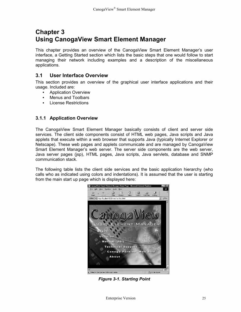
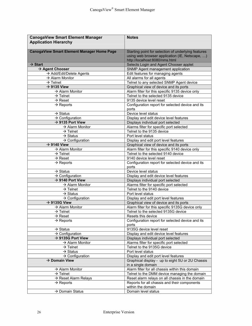
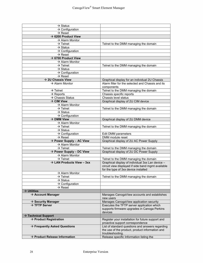
The following table lists the client side services and the basic application hierarchy (whocalls who as indicated using colors and indentations). It is assumed that the user is startingfrom the main start up page which is displayed here:
Figure 3-1. Starting Point
CanogaView® Smart Element Manager
26 Enterprise Version
CanogaView Smart Element Manager Application Hierarchy
Notes
CanogaView Smart Element Manager Home Page Starting point for selection of underlying featuresusing web browser application (IE, Netscape, …)http://localhost:8080/nms.html
� Start Selects Login and Agent Chooser applet � Agent Chooser SNMP Agent management application � Add/Edit/Delete Agents Edit features for managing agents � Alarm Monitor All alarms for all agents � Telnet Telnet to any selected SNMP Agent device � 9135 View Graphical view of device and its ports � Alarm Monitor Alarm filter for this specific 9135 device only � Telnet Telnet to the selected 9135 device � Reset 9135 device level reset � Reports Configuration report for selected device and its
ports � Status Device level status � Configuration Display and edit device level features � 9135 Port View Displays individual port selected � Alarm Monitor Alarms filter for specific port selected � Telnet Telnet to the 9135 device � Status Port level status � Configuration Display and edit port level features � 9140 View Graphical view of device and its ports � Alarm Monitor Alarm filter for this specific 9140 device only � Telnet Telnet to the selected 9140 device � Reset 9140 device level reset � Reports Configuration report for selected device and its
ports � Status Device level status � Configuration Display and edit device level features � 9140 Port View Displays individual port selected � Alarm Monitor Alarms filter for specific port selected � Telnet Telnet to the 9140 device � Status Port level status � Configuration Display and edit port level features � 9135G View Graphical view of device and its ports � Alarm Monitor Alarm filter for this specific 9135G device only � Telnet Telnet to the selected 9135G device � Reset Resets this device � Reports Configuration report for selected device and its
ports � Status 9135G device level reset � Configuration Display and edit device level features � 9135G Port View Displays individual port selected � Alarm Monitor Alarms filter for specific port selected � Telnet Telnet to the 9135G device � Status Port level status � Configuration Display and edit port level features � Domain View Graphical display - up to eight 5U or 2U Chassis
in a single domain � Alarm Monitor Alarm filter for all chassis within this domain � Telnet Telnet to the DMM device managing the domain � Reset Alarm Relays Reset alarm relays on all chassis in the domain � Reports Reports for all chassis and their components
within the domain � Domain Status Domain level status

CanogaView® Smart Element Manager
Enterprise Version 27
� 5U Chassis View Graphical display for an individual 5U Chassis � Alarm Monitor Alarm filter for the selected Chassis and its
components � Telnet Telnet to the DMM managing the domain � Reports Chassis specific reports for this chassis and all of
its components � Chassis Status Chassis level status � CIM View Graphical display of CIM device � Alarm Monitor Alarm filter for this device only � Telnet Telnet to the DMM managing the domain � Status CIM module level status � Configuration Display and edit CIM level features � DMM View Graphical display of DMM device � Alarm Monitor Alarms filtered for this device only � Telnet Telnet to the DMM managing the domain � Status DMM module level status � Configuration Display and edit DMM level features � Reset Reset the selected DMM device � Power Supply – AC View Graphical display of 5U AC Power Supply � Alarm Monitor Alarms filtered for this device only � Telnet Telnet to the DMM managing the domain � Power Supply – DC View Graphical display of 5U DC Power Supply � Alarm Monitor Alarms filtered for this device only � Telnet Telnet to the DMM managing the domain � LAN Extension Products View Graphical display of 1230 device and installed 3xx
slot devices. This level will be bypassed if theuser selects one of the devices within a slot vs the1230 device.
� Alarm Monitor Alarms filtered for this 1230 device and installeddevices
� Telnet Telnet to the DMM managing the domain � Status 1230 module level status � Configuration Display and edit 1230 device level features � Reset Reset or Reset/Swap options for one or all
installed slot devices � Device 3xx View Graphical display of individual 3xx Lan device –
circuit view displayed if side band mgmt availablefor the type of 3xx device installed
� Alarm Monitor Alarm filter for the 3xx device selected � Telnet Telnet to the DMM managing the domain � Status 3xx module level status � Configuration Display and edit 3xx device level features � Reset Reset the selected 3xx device � Modem Product View Graphical display of T3 2x4x or T1 2x6x products
showing circuit level with redundancy if installed � Alarm Monitor Alarms filtered for all modems on this circuit –
local, remote and redundant � Telnet Telnet to the DMM managing the domain � Status Circuit level status � Configuration Display and edit modem level features � Reset Circuit level reset for one or more modems � 600x Product View � Alarm Monitor Alarms filtered for the 600x device selected � Telnet Telnet to the DMM managing the domain � Status � Configuration � Reset � 6100 Product View � Alarm Monitor � Telnet Telnet to the DMM managing the domain
CanogaView® Smart Element Manager
28 Enterprise Version
� Status � Configuration � Reset � 6200 Product View � Alarm Monitor � Telnet Telnet to the DMM managing the domain � Status � Configuration � Reset � 6700 Product View � Alarm Monitor � Telnet Telnet to the DMM managing the domain � Status � Configuration � Reset � 2U Chassis View Graphical display for an individual 2U Chassis � Alarm Monitor Alarm filter for the selected and Chassis and its
components � Telnet Telnet to the DMM managing the domain � Reports Chassis specific reports � Chassis Status Chassis level status � CIM View Graphical display of 2U CIM device � Alarm Monitor � Telnet Telnet to the DMM managing the domain � Status � Configuration � DMM View Graphical display of 2U DMM device � Alarm Monitor � Telnet Telnet to the DMM managing the domain � Status � Configuration Edit DMM parameters � Reset DMM module reset � Power Supply – AC View Graphical display of 2U AC Power Supply � Alarm Monitor � Telnet Telnet to the DMM managing the domain � Power Supply – DC View Graphical display of 2U DC Power Supply � Alarm Monitor � Telnet Telnet to the DMM managing the domain � LAN Products View – 3xx Graphical display of individual 3xx Lan device –
circuit view displayed if side band mgmt availablefor the type of 3xx device installed
� Alarm Monitor � Telnet Telnet to the DMM managing the domain � Status � Configuration � Reset� Utilities � Account Manager Manages CanogaView accounts and establishes
new users � Security Manager Manages CanogaView application security � TFTP Server Executes the TFTP server application which
supports firmware upgrades in Canoga Perkinsdevices
� Technical Support � Product Registration Register your installation for future support and
proactive support correspondence � Frequently Asked Questions List of standard questions and answers regarding
the use of the product, product information andtroubleshooting.
� Product Release Information Release specific Information listing the
CanogaView® Smart Element Manager
Enterprise Version 29
enhancements and known problems � Installation Notes Installation notes for Windows, Sun and HP
Installation � Canoga Perkins Technical Support link Direct link to Canoga Perkins corporate web site
support page � Email support link Link for Email support to Canoga Perkins support
group� Canoga Perkins web site link Link to Canoga Perkins Corporate web site at
www.canoga.com� About Version and copyright statements
3.1.2 Menus and Toolbars
Toolbar icons appear in the upper left corner of a page under the drop-down menu bar.Icons reflect the same items as will be found in the drop-down menus.
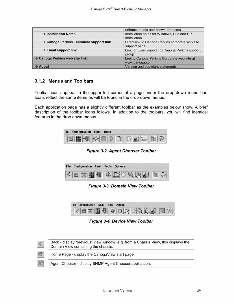
Each application page has a slightly different toolbar as the examples below show. A briefdescription of the toolbar icons follows. In addition to the toolbars, you will find identicalfeatures in the drop down menus.
Figure 3-2. Agent Chooser Toolbar
Figure 3-3. Domain View Toolbar
Figure 3-4. Device View Toolbar
Back - display “previous” view window; e.g. from a Chassis View, this displays theDomain View containing the chassis.
Home Page - display the CanogaView start page.
Agent Chooser - display SNMP Agent Chooser application.
CanogaView® Smart Element Manager
30 Enterprise Version
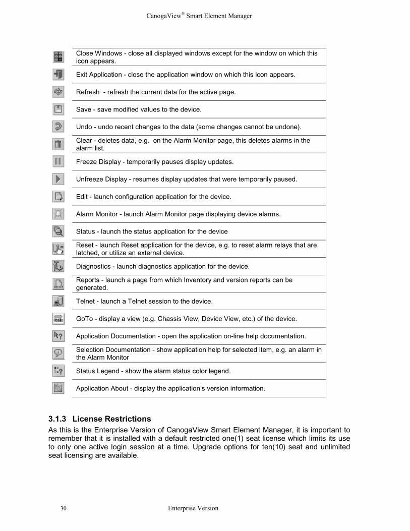
Close Windows - close all displayed windows except for the window on which thisicon appears.
Exit Application - close the application window on which this icon appears.
Refresh - refresh the current data for the active page.
Save - save modified values to the device.
Undo - undo recent changes to the data (some changes cannot be undone).
Clear - deletes data, e.g. on the Alarm Monitor page, this deletes alarms in thealarm list.
Freeze Display - temporarily pauses display updates.
Unfreeze Display - resumes display updates that were temporarily paused.
Edit - launch configuration application for the device.
Alarm Monitor - launch Alarm Monitor page displaying device alarms.
Status - launch the status application for the device
Reset - launch Reset application for the device, e.g. to reset alarm relays that arelatched, or utilize an external device.
Diagnostics - launch diagnostics application for the device.
Reports - launch a page from which Inventory and version reports can begenerated.
Telnet - launch a Telnet session to the device.
GoTo - display a view (e.g. Chassis View, Device View, etc.) of the device.
Application Documentation - open the application on-line help documentation.
Selection Documentation - show application help for selected item, e.g. an alarm inthe Alarm Monitor
Status Legend - show the alarm status color legend.
Application About - display the application’s version information.
3.1.3 License RestrictionsAs this is the Enterprise Version of CanogaView Smart Element Manager, it is important toremember that it is installed with a default restricted one(1) seat license which limits its useto only one active login session at a time. Upgrade options for ten(10) seat and unlimitedseat licensing are available.
CanogaView® Smart Element Manager
Enterprise Version 31
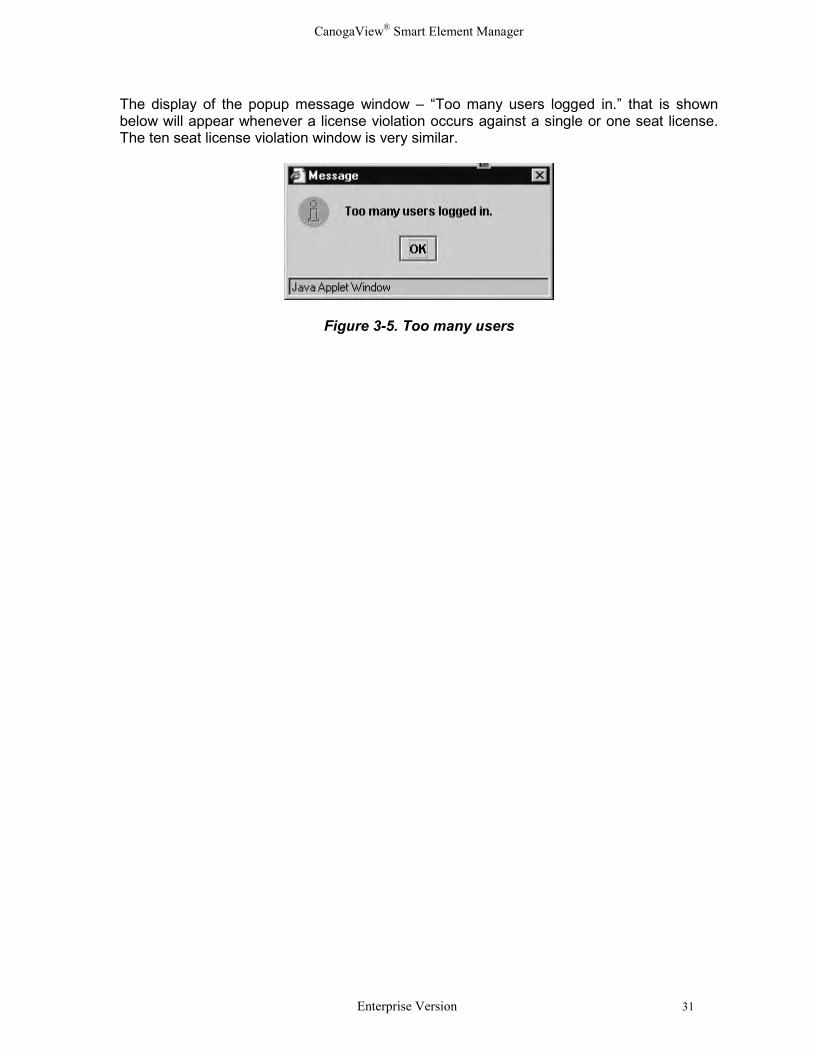
The display of the popup message window – “Too many users logged in.” that is shownbelow will appear whenever a license violation occurs against a single or one seat license.The ten seat license violation window is very similar.
Figure 3-5. Too many users
CanogaView® Smart Element Manager
32 Enterprise Version
3.2 Getting Started
Once CanogaView Smart Element Manager is installed you are ready to start using it tomanage your Canoga Perkin’s Networking equipment.
3.2.1 Opening CanogaView Smart Element Manager
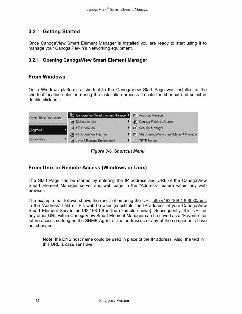
From Windows
On a Windows platform, a shortcut to the CanogaView Start Page was installed at theshortcut location selected during the installation process. Locate the shortcut and select ordouble click on it.
Figure 3-6. Shortcut Menu
From Unix or Remote Access (Windows or Unix)
The Start Page can be started by entering the IP address and URL of the CanogaViewSmart Element Manager server and web page in the “Address” feature within any webbrowser.
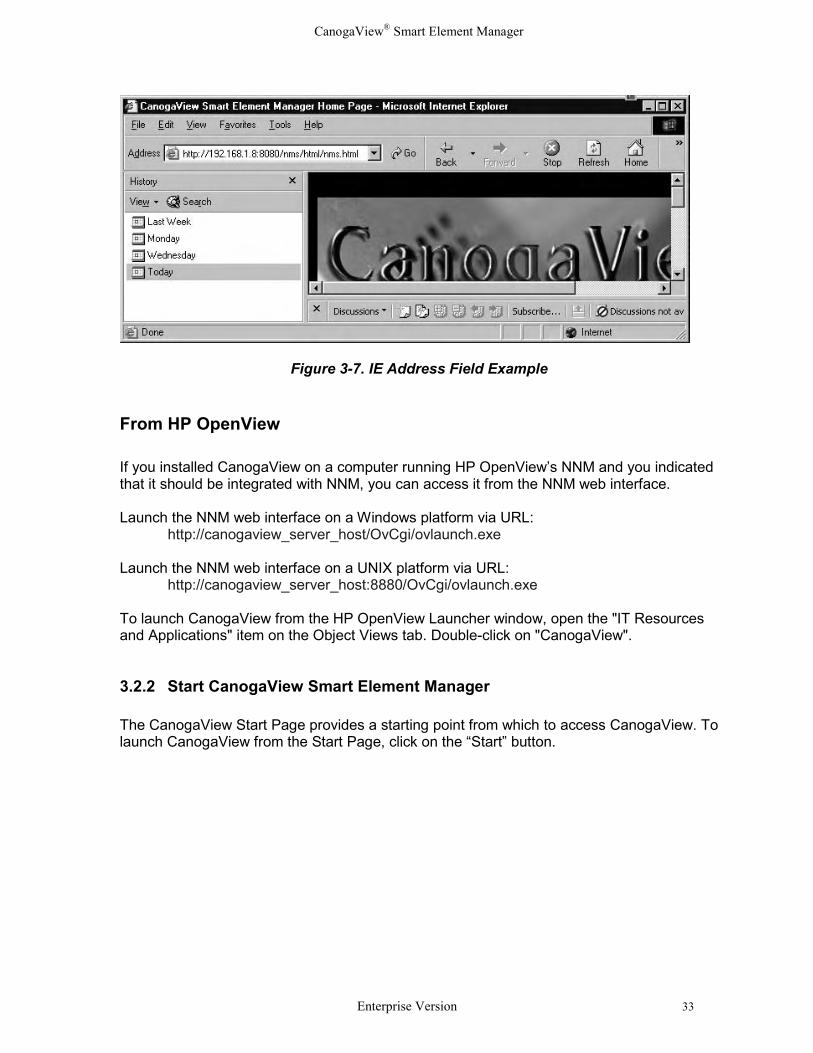
The example that follows shows the result of entering the URL http://192.168.1.8:8080/nmsin the “Address” field of IE’s web browser (substitute the IP address of your CanogaViewSmart Element Server for 192.168.1.8 in the example shown). Subsequently, this URL orany other URL within CanogaView Smart Element Manager can be saved as a “Favorite” forfuture access so long as the SNMP Agent or the addresses of any of the components havenot changed.
Note: the DNS host name could be used in place of the IP address. Also, the text inthis URL is case sensitive.
CanogaView® Smart Element Manager
Enterprise Version 33
Figure 3-7. IE Address Field Example
From HP OpenView
If you installed CanogaView on a computer running HP OpenView’s NNM and you indicatedthat it should be integrated with NNM, you can access it from the NNM web interface.
Launch the NNM web interface on a Windows platform via URL:http://canogaview_server_host/OvCgi/ovlaunch.exe
Launch the NNM web interface on a UNIX platform via URL:http://canogaview_server_host:8880/OvCgi/ovlaunch.exe
To launch CanogaView from the HP OpenView Launcher window, open the "IT Resourcesand Applications" item on the Object Views tab. Double-click on "CanogaView".
3.2.2 Start CanogaView Smart Element Manager
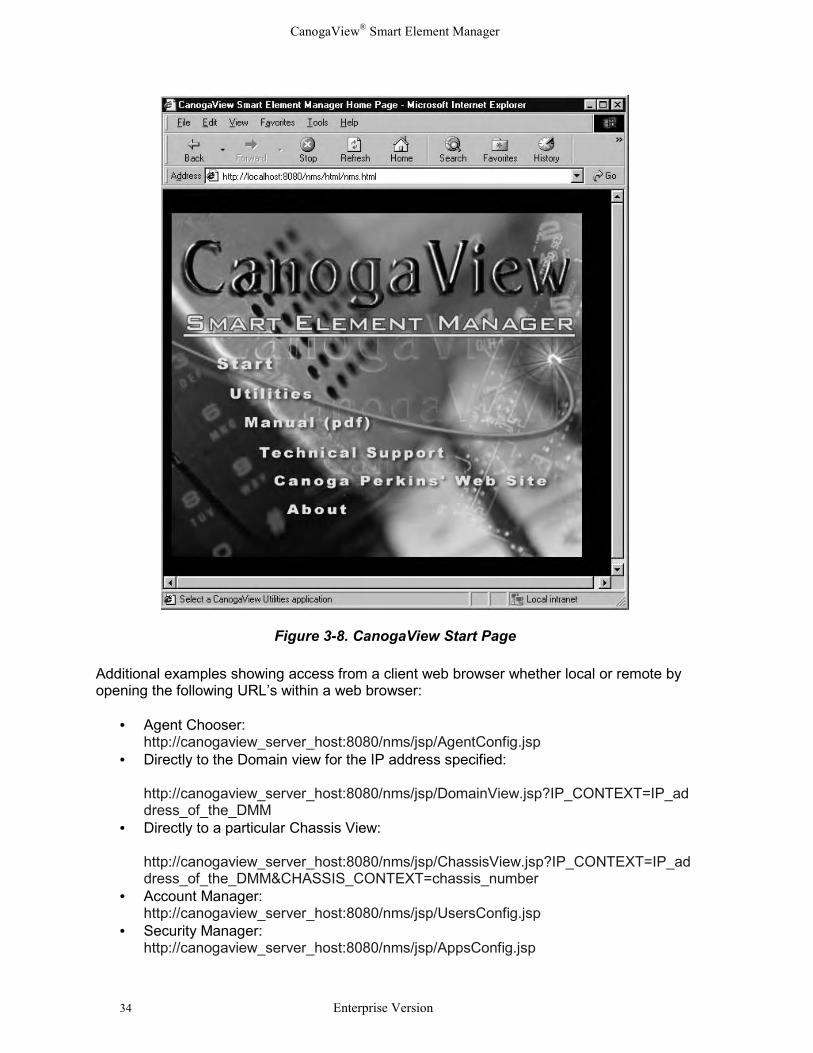
The CanogaView Start Page provides a starting point from which to access CanogaView. Tolaunch CanogaView from the Start Page, click on the “Start” button.
CanogaView® Smart Element Manager
34 Enterprise Version
Figure 3-8. CanogaView Start Page
Additional examples showing access from a client web browser whether local or remote byopening the following URL’s within a web browser:
• Agent Chooser:http://canogaview_server_host:8080/nms/jsp/AgentConfig.jsp
• Directly to the Domain view for the IP address specified:
http://canogaview_server_host:8080/nms/jsp/DomainView.jsp?IP_CONTEXT=IP_address_of_the_DMM
• Directly to a particular Chassis View:
http://canogaview_server_host:8080/nms/jsp/ChassisView.jsp?IP_CONTEXT=IP_address_of_the_DMM&CHASSIS_CONTEXT=chassis_number
• Account Manager:http://canogaview_server_host:8080/nms/jsp/UsersConfig.jsp
• Security Manager:http://canogaview_server_host:8080/nms/jsp/AppsConfig.jsp
CanogaView® Smart Element Manager
Enterprise Version 35
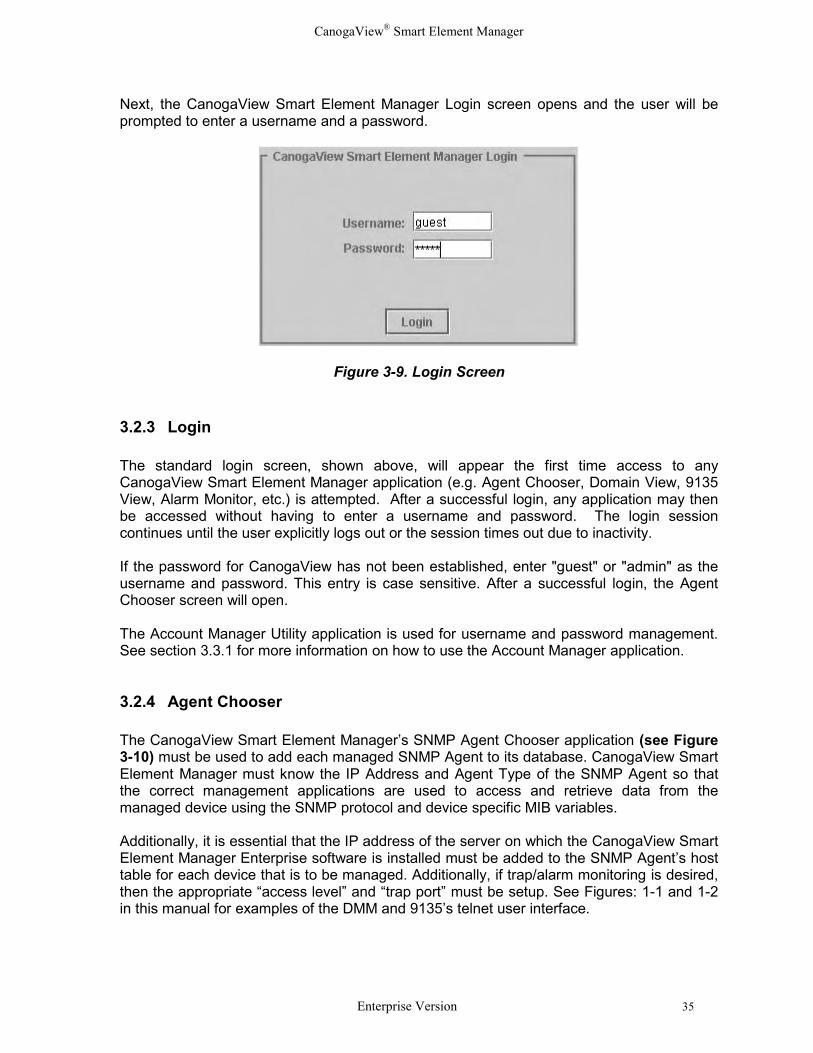
Next, the CanogaView Smart Element Manager Login screen opens and the user will beprompted to enter a username and a password.
Figure 3-9. Login Screen
3.2.3 Login
The standard login screen, shown above, will appear the first time access to anyCanogaView Smart Element Manager application (e.g. Agent Chooser, Domain View, 9135View, Alarm Monitor, etc.) is attempted. After a successful login, any application may thenbe accessed without having to enter a username and password. The login sessioncontinues until the user explicitly logs out or the session times out due to inactivity.
If the password for CanogaView has not been established, enter "guest" or "admin" as theusername and password. This entry is case sensitive. After a successful login, the AgentChooser screen will open.
The Account Manager Utility application is used for username and password management.See section 3.3.1 for more information on how to use the Account Manager application.
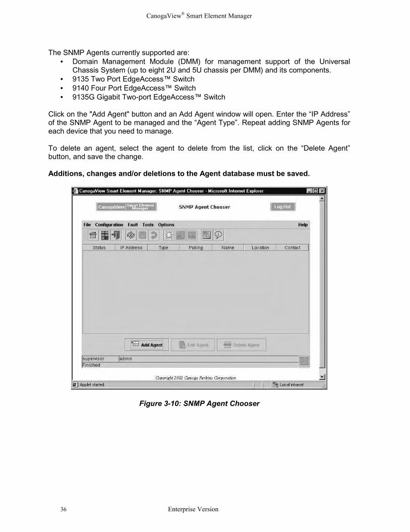
3.2.4 Agent Chooser
The CanogaView Smart Element Manager’s SNMP Agent Chooser application (see Figure3-10) must be used to add each managed SNMP Agent to its database. CanogaView SmartElement Manager must know the IP Address and Agent Type of the SNMP Agent so thatthe correct management applications are used to access and retrieve data from themanaged device using the SNMP protocol and device specific MIB variables.
Additionally, it is essential that the IP address of the server on which the CanogaView SmartElement Manager Enterprise software is installed must be added to the SNMP Agent’s hosttable for each device that is to be managed. Additionally, if trap/alarm monitoring is desired,then the appropriate “access level” and “trap port” must be setup. See Figures: 1-1 and 1-2in this manual for examples of the DMM and 9135’s telnet user interface.
CanogaView® Smart Element Manager
36 Enterprise Version
The SNMP Agents currently supported are:• Domain Management Module (DMM) for management support of the Universal
Chassis System (up to eight 2U and 5U chassis per DMM) and its components. • 9135 Two Port EdgeAccess™ Switch • 9140 Four Port EdgeAccess™ Switch• 9135G Gigabit Two-port EdgeAccess™ Switch
Click on the "Add Agent" button and an Add Agent window will open. Enter the “IP Address”of the SNMP Agent to be managed and the “Agent Type”. Repeat adding SNMP Agents foreach device that you need to manage.
To delete an agent, select the agent to delete from the list, click on the “Delete Agent”button, and save the change.
Additions, changes and/or deletions to the Agent database must be saved.
Figure 3-10: SNMP Agent Chooser
CanogaView® Smart Element Manager
Enterprise Version 37
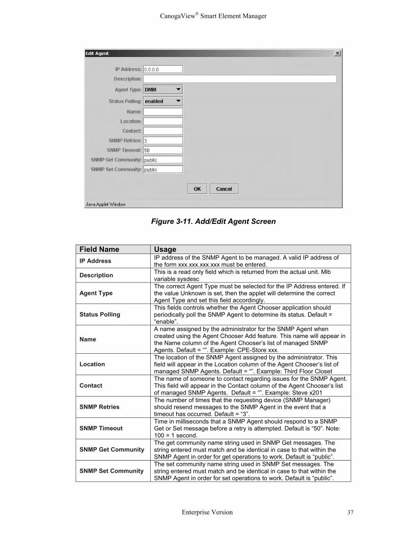
Figure 3-11. Add/Edit Agent Screen
Field Name UsageIP Address IP address of the SNMP Agent to be managed. A valid IP address of
the form xxx.xxx.xxx.xxx must be entered.
Description This is a read only field which is returned from the actual unit. Mibvariable sysdesc
Agent TypeThe correct Agent Type must be selected for the IP Address entered. Ifthe value Unknown is set, then the applet will determine the correctAgent Type and set this field accordingly.
Status PollingThis fields controls whether the Agent Chooser application shouldperiodically poll the SNMP Agent to determine its status. Default =“enable”.
NameA name assigned by the administrator for the SNMP Agent whencreated using the Agent Chooser Add feature. This name will appear inthe Name column of the Agent Chooser’s list of managed SNMPAgents. Default = “”. Example: CPE-Store xxx.
LocationThe location of the SNMP Agent assigned by the administrator. Thisfield will appear in the Location column of the Agent Chooser’s list ofmanaged SNMP Agents. Default = “”. Example: Third Floor Closet
ContactThe name of someone to contact regarding issues for the SNMP Agent.This field will appear in the Contact column of the Agent Chooser’s listof managed SNMP Agents. Default = “”. Example: Steve x201
SNMP RetriesThe number of times that the requesting device (SNMP Manager)should resend messages to the SNMP Agent in the event that atimeout has occurred. Default = “3”.
SNMP TimeoutTime in milliseconds that a SNMP Agent should respond to a SNMPGet or Set message before a retry is attempted. Default is “50”. Note:100 = 1 second.
SNMP Get CommunityThe get community name string used in SNMP Get messages. Thestring entered must match and be identical in case to that within theSNMP Agent in order for get operations to work. Default is “public”.
SNMP Set CommunityThe set community name string used in SNMP Set messages. Thestring entered must match and be identical in case to that within theSNMP Agent in order for set operations to work. Default is “public”.
CanogaView® Smart Element Manager
38 Enterprise Version
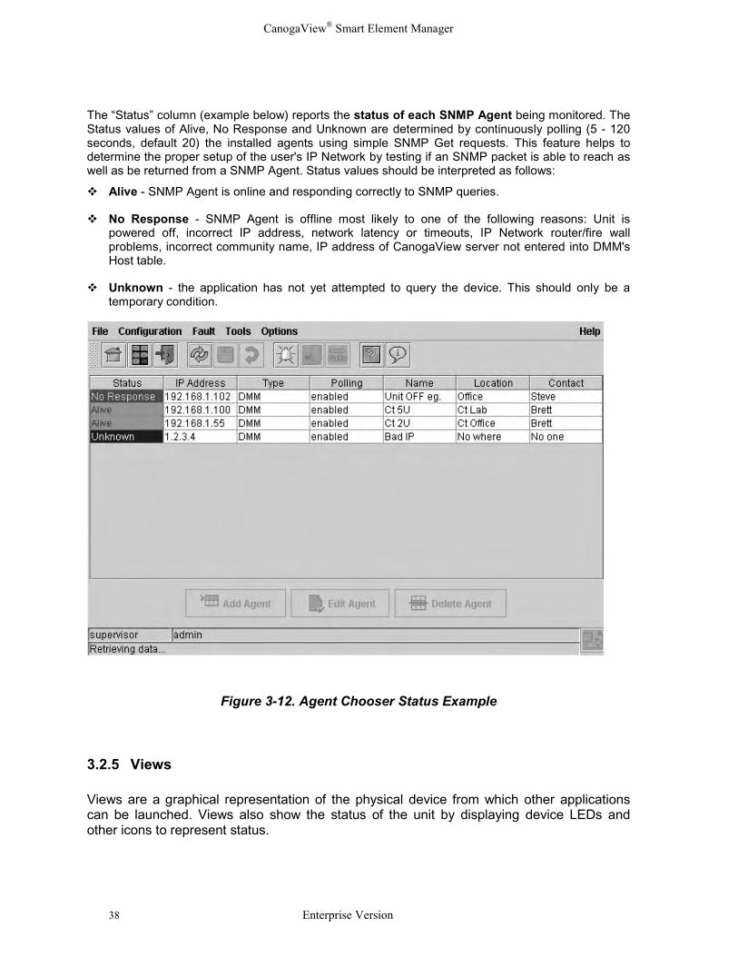
The “Status” column (example below) reports the status of each SNMP Agent being monitored. TheStatus values of Alive, No Response and Unknown are determined by continuously polling (5 - 120seconds, default 20) the installed agents using simple SNMP Get requests. This feature helps todetermine the proper setup of the user's IP Network by testing if an SNMP packet is able to reach aswell as be returned from a SNMP Agent. Status values should be interpreted as follows:
� Alive - SNMP Agent is online and responding correctly to SNMP queries.
� No Response - SNMP Agent is offline most likely to one of the following reasons: Unit ispowered off, incorrect IP address, network latency or timeouts, IP Network router/fire wallproblems, incorrect community name, IP address of CanogaView server not entered into DMM'sHost table.
� Unknown - the application has not yet attempted to query the device. This should only be atemporary condition.
Figure 3-12. Agent Chooser Status Example
3.2.5 Views
Views are a graphical representation of the physical device from which other applicationscan be launched. Views also show the status of the unit by displaying device LEDs andother icons to represent status.
CanogaView® Smart Element Manager
Enterprise Version 39
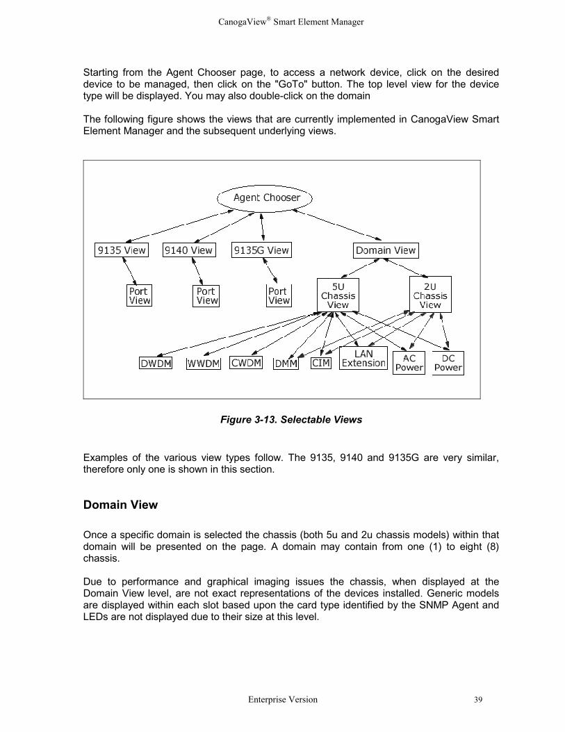
Starting from the Agent Chooser page, to access a network device, click on the desireddevice to be managed, then click on the "GoTo" button. The top level view for the devicetype will be displayed. You may also double-click on the domain
The following figure shows the views that are currently implemented in CanogaView SmartElement Manager and the subsequent underlying views.
Figure 3-13. Selectable Views
Examples of the various view types follow. The 9135, 9140 and 9135G are very similar,therefore only one is shown in this section.
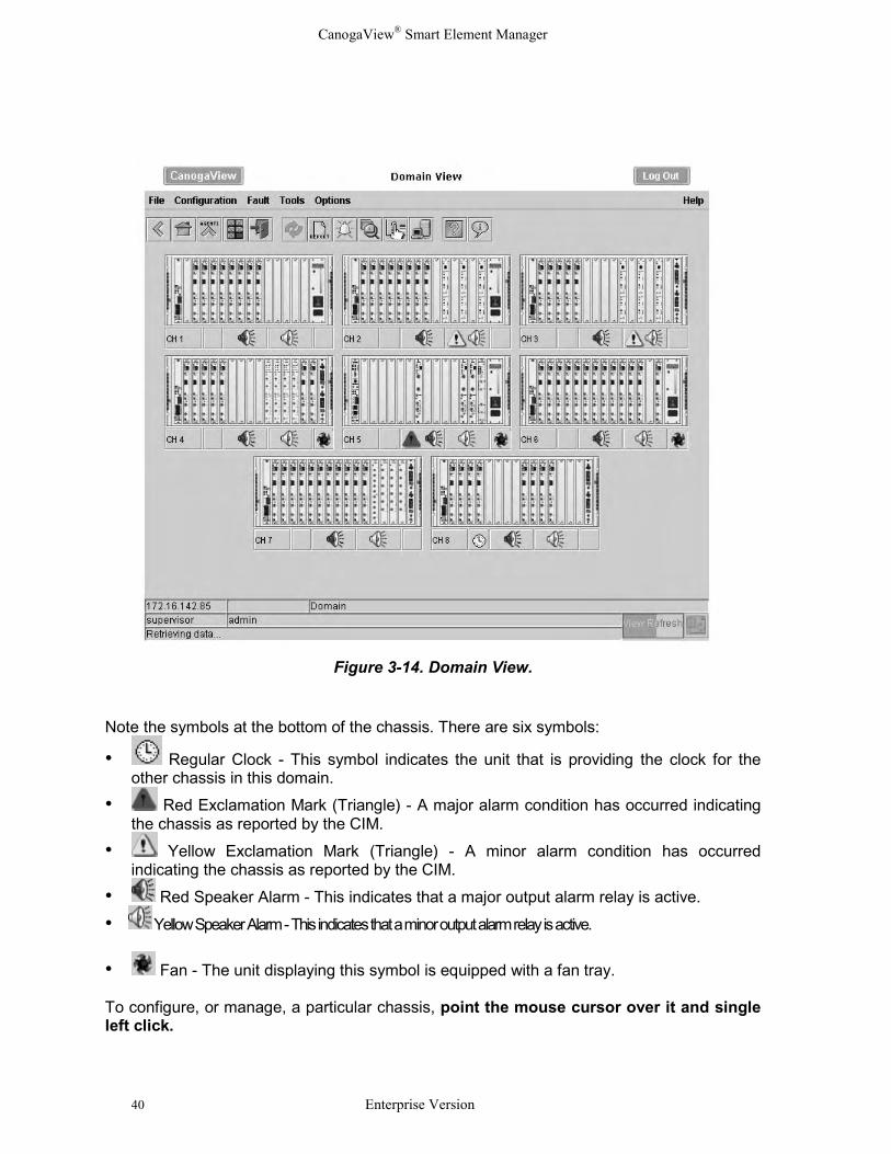
Domain View
Once a specific domain is selected the chassis (both 5u and 2u chassis models) within thatdomain will be presented on the page. A domain may contain from one (1) to eight (8)chassis.
Due to performance and graphical imaging issues the chassis, when displayed at theDomain View level, are not exact representations of the devices installed. Generic modelsare displayed within each slot based upon the card type identified by the SNMP Agent andLEDs are not displayed due to their size at this level.
CanogaView® Smart Element Manager
40 Enterprise Version
Figure 3-14. Domain View.
Note the symbols at the bottom of the chassis. There are six symbols:
• Regular Clock - This symbol indicates the unit that is providing the clock for theother chassis in this domain.
• Red Exclamation Mark (Triangle) - A major alarm condition has occurred indicatingthe chassis as reported by the CIM.
• Yellow Exclamation Mark (Triangle) - A minor alarm condition has occurredindicating the chassis as reported by the CIM.
• Red Speaker Alarm - This indicates that a major output alarm relay is active.
• Yellow Speaker Alarm - This indicates that a minor output alarm relay is active.
• Fan - The unit displaying this symbol is equipped with a fan tray.
To configure, or manage, a particular chassis, point the mouse cursor over it and singleleft click.
CanogaView® Smart Element Manager
Enterprise Version 41
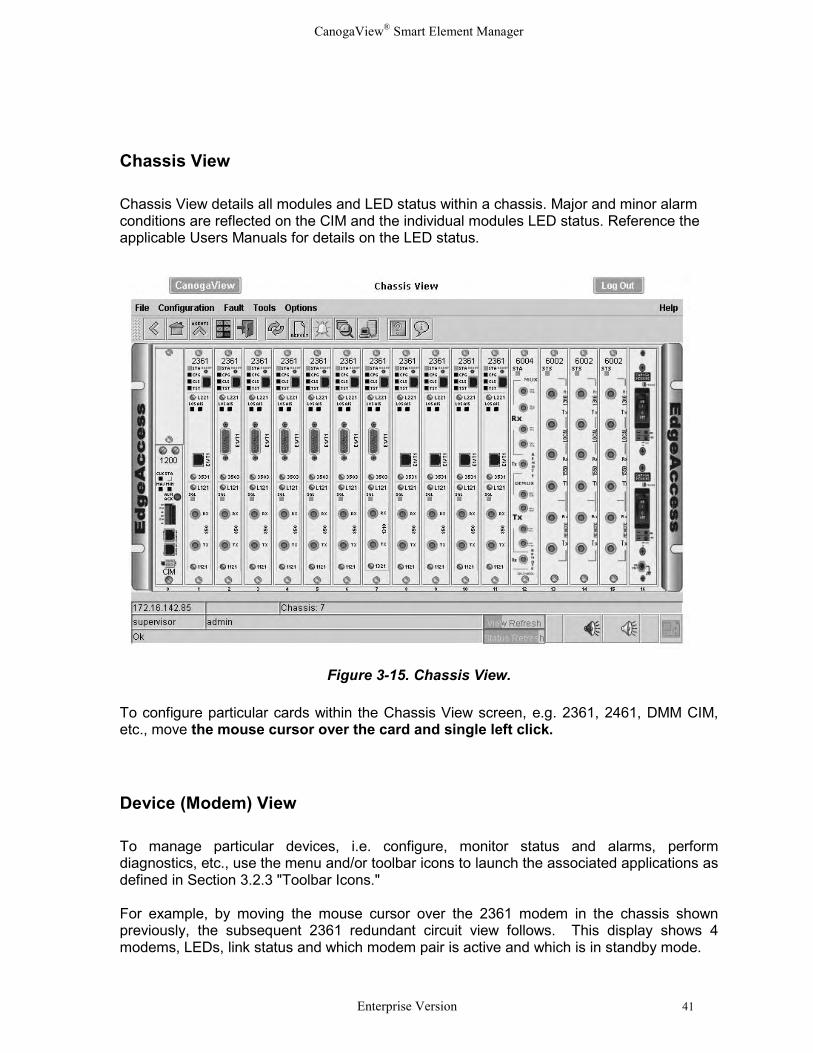
Chassis View
Chassis View details all modules and LED status within a chassis. Major and minor alarmconditions are reflected on the CIM and the individual modules LED status. Reference theapplicable Users Manuals for details on the LED status.
Figure 3-15. Chassis View.
To configure particular cards within the Chassis View screen, e.g. 2361, 2461, DMM CIM,etc., move the mouse cursor over the card and single left click.
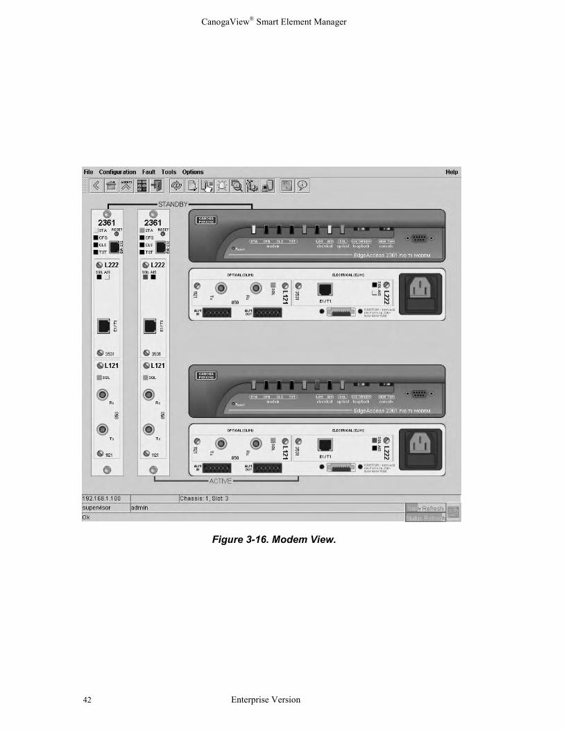
Device (Modem) View
To manage particular devices, i.e. configure, monitor status and alarms, performdiagnostics, etc., use the menu and/or toolbar icons to launch the associated applications asdefined in Section 3.2.3 "Toolbar Icons."
For example, by moving the mouse cursor over the 2361 modem in the chassis shownpreviously, the subsequent 2361 redundant circuit view follows. This display shows 4modems, LEDs, link status and which modem pair is active and which is in standby mode.
CanogaView® Smart Element Manager
42 Enterprise Version
Figure 3-16. Modem View.
CanogaView® Smart Element Manager
Enterprise Version 43
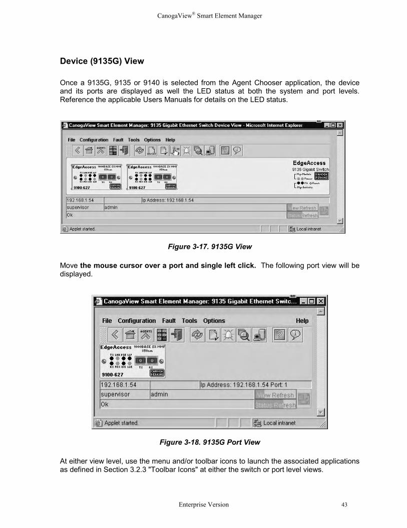
Device (9135G) View
Once a 9135G, 9135 or 9140 is selected from the Agent Chooser application, the deviceand its ports are displayed as well the LED status at both the system and port levels.Reference the applicable Users Manuals for details on the LED status.
Figure 3-17. 9135G View
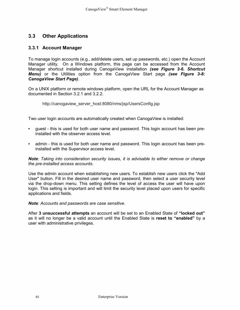
Move the mouse cursor over a port and single left click. The following port view will bedisplayed.
Figure 3-18. 9135G Port View
At either view level, use the menu and/or toolbar icons to launch the associated applicationsas defined in Section 3.2.3 "Toolbar Icons" at either the switch or port level views.
CanogaView® Smart Element Manager
44 Enterprise Version
3.3 Other Applications
3.3.1 Account Manager
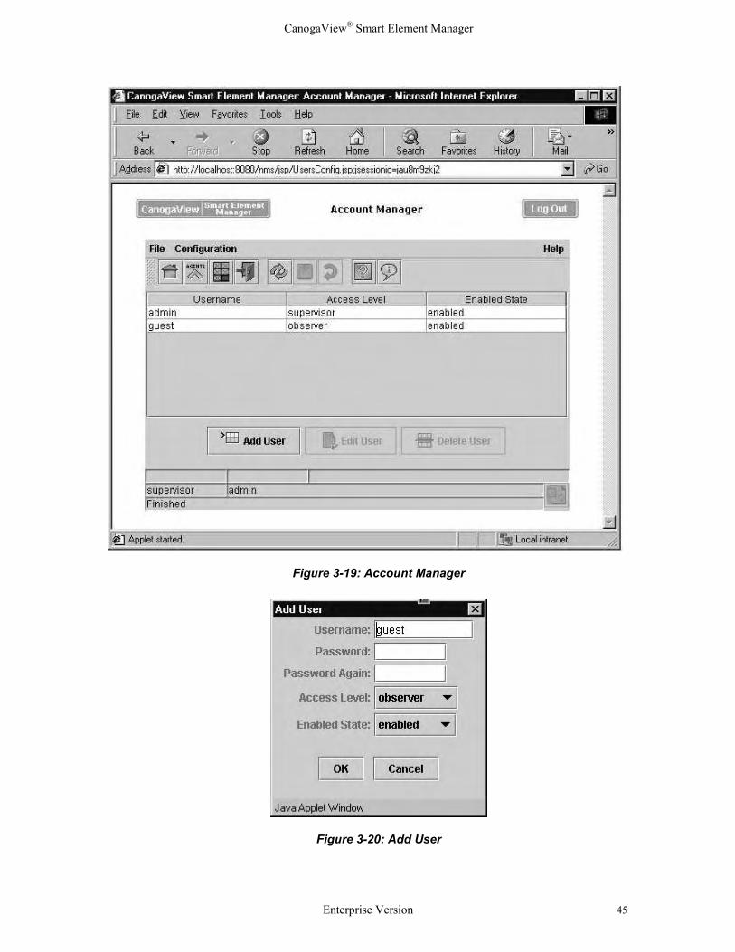
To manage login accounts (e.g., add/delete users, set up passwords, etc.) open the AccountManager utility. On a Windows platform, this page can be accessed from the AccountManager shortcut installed during CanogaView installation (see Figure 3-6. ShortcutMenu) or the Utilities option from the CanogaView Start page (see Figure 3-8:CanogaView Start Page).
On a UNIX platform or remote windows platform, open the URL for the Account Manager asdocumented in Section 3.2.1 and 3.2.2.
http://canogaview_server_host:8080/nms/jsp/UsersConfig.jsp
Two user login accounts are automatically created when CanogaView is installed:
• guest - this is used for both user name and password. This login account has been pre-installed with the observer access level.
• admin - this is used for both user name and password. This login account has been pre-installed with the Supervisor access level.
Note: Taking into consideration security issues, it is advisable to either remove or changethe pre-installed access accounts. Use the admin account when establishing new users. To establish new users click the "AddUser" button. Fill in the desired user name and password, then select a user security levelvia the drop-down menu. This setting defines the level of access the user will have uponlogin. This setting is important and will limit the security level placed upon users for specificapplications and fields.
Note: Accounts and passwords are case sensitive.
After 3 unsuccessful attempts an account will be set to an Enabled State of “locked out”as it will no longer be a valid account until the Enabled State is reset to “enabled” by auser with administrative privileges.
CanogaView® Smart Element Manager
Enterprise Version 45
Figure 3-19: Account Manager
Figure 3-20: Add User
CanogaView® Smart Element Manager
46 Enterprise Version
3.3.2 Alarm Monitor
Each graphical views have a button with a yellow bell; the Alarm Monitor. The Alarm Monitorregisters to receive events that originate from the chassis, device, etc.
When initiated, the Alarm Monitor screen will open with a history of the latest alarms. Thismonitor operates in real time, thus as one alarm is generated it is reflected in the alarms listwhile the last alarm in the history file is removed when the maximum number of alarms isreceived.
An alarm database stores Historical Alarm Events for monitoring and reporting purposes. Bydefault, the system is installed with a utility which runs every night at midnight which purgesall alarms older than 30 days to a txt file. The purpose of this utility is to prevent thedatabase from becoming too big as the performance of the reporting applications will beimpacted significantly.
To modify the execution of this utility, find the "service.conf" file within the directory hierarchywhere you installed CanogaView Smart Element Manager, and using a standard text editormodify the line which starts with "EventEngine". You will see two variables toward the end ofthe line (see below) that you can modify to turn this feature "-exportalarms on" or "-exportalarms off", the number of days of which events are considered old "-exportage 30"and the output location where the exported events should be placed "-exportdir xxxx":EventEngine ................... -exportalarms on -exportage 30 -exportdir xxxxxx is the name of the directory where exported event files will be placed. Note that the txtformat of these files created allow them to be imported into other desktop applications. Also,each time the purge utility is run a new file with a new date/time stamp as its filename iscreated which allows one to merge and search through months or years of alarminformation.
The Alarm Monitor displays Active alarms and Historical alarms. The Active list will showonly those received events that have not yet been cleared (thereby showing the currentstate of the device(s) monitored). The historical list will show all events that have beenreceived and subsequently cleared. Both lists can be resized.
Alarm Event Correlation services are present such that Link Up events clear Link Downevents, Cold Starts clear all events against a device, Card Inserted events clear CardRemoved events, Active Optical Link Sync OK clear Active Optical Link Sync Bad events,etc..
Alarm Filtering exists such that whenever a user selects the Alarm Monitor option; allAlarms displayed and subsequently monitored will be that at the device level selected aswell as all of its components or underlying views. Thus the Alarm Monitor is opened at theAgent Chooser level then all alarm events for all SNMP agents will be displayed.Subsequently, if the user selects the application while at the Device level, then all alarmevents for this device as well as any of it remote managed units will be displayed andmonitored.
CanogaView® Smart Element Manager
Enterprise Version 47
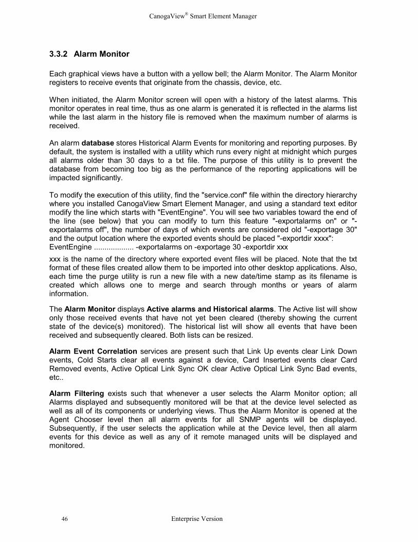
An example of alarms when selected at the Agent Chooser level is displayed below. Notethat alarms against all of the SNMP Agents in the Agent Chooser’s list will be displayed.
Figure 3-21. Alarm Monitor – All Alarms Filter
CanogaView® Smart Element Manager
48 Enterprise Version
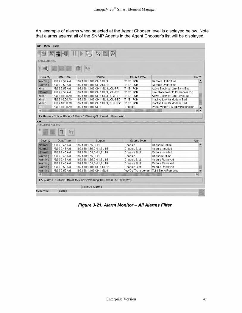
Next, an example of selecting the alarm button at a device level follows:
Figure 3-22. Alarm Monitor – Filtered Example
Other Alarm Monitoring features include: � Select All - a short cut for selecting all of the active alarm events.
� Telnet - select an alarm event and launch a telnet session using the IP address ofthe SNMP Agent.
� Goto - select an alarm and go right to the source of the problem, by launching anGraphical View of the device from which all CanogaView applications can beaccessed.
� Clear Active - allows a user to manually clear an active alarm.
� Freeze - allows a user to freeze and read the display during times of high alarmactivity.
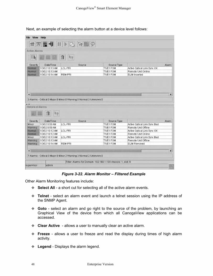
� Legend - Displays the alarm legend.
CanogaView® Smart Element Manager
Enterprise Version 49
Figure 3-23. Alarm Legend
CanogaView® Smart Element Manager
50 Enterprise Version
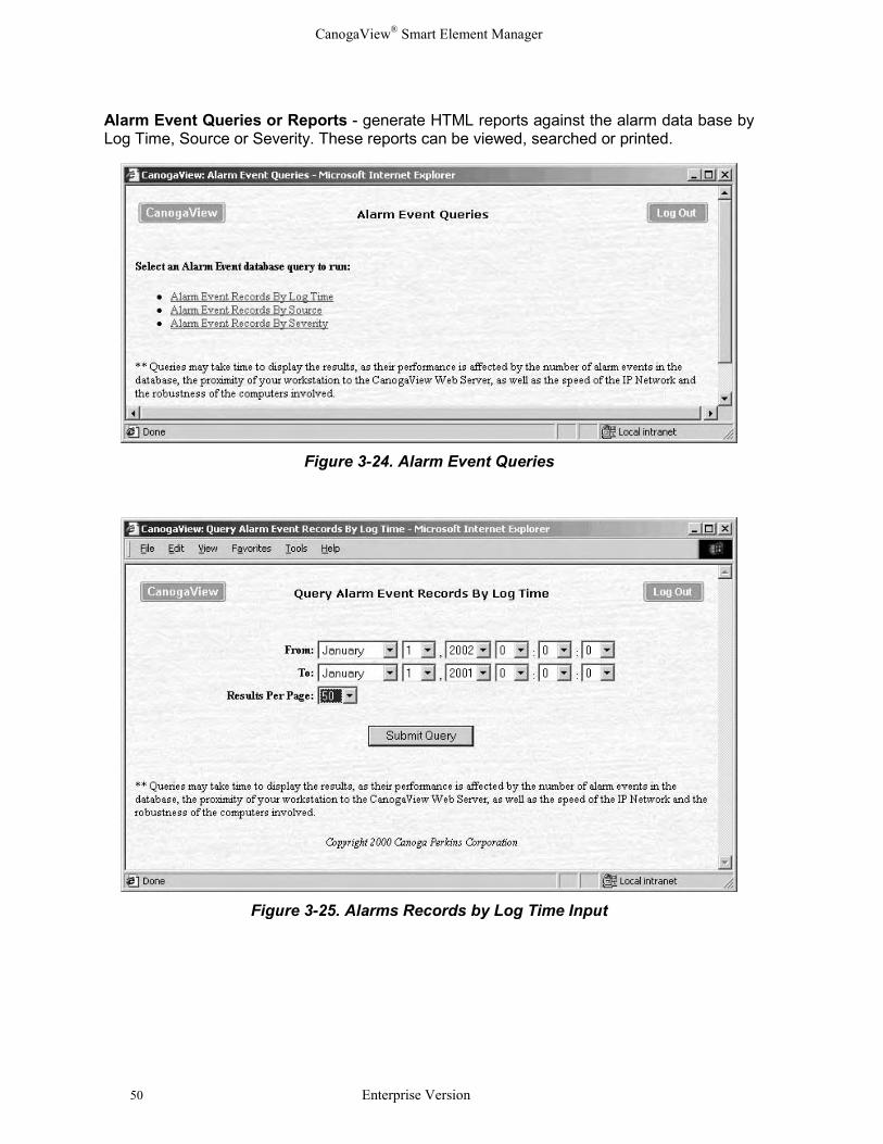
Alarm Event Queries or Reports - generate HTML reports against the alarm data base byLog Time, Source or Severity. These reports can be viewed, searched or printed.
Figure 3-24. Alarm Event Queries
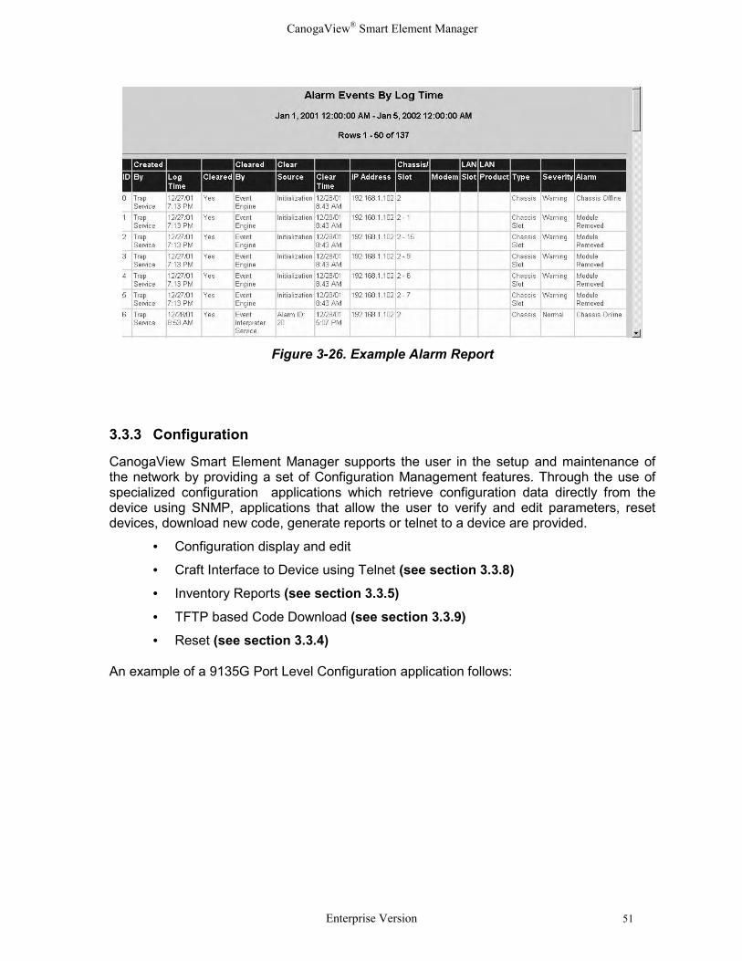
Figure 3-25. Alarms Records by Log Time Input
CanogaView® Smart Element Manager
Enterprise Version 51
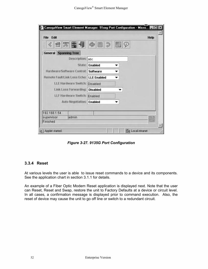
Figure 3-26. Example Alarm Report
3.3.3 Configuration
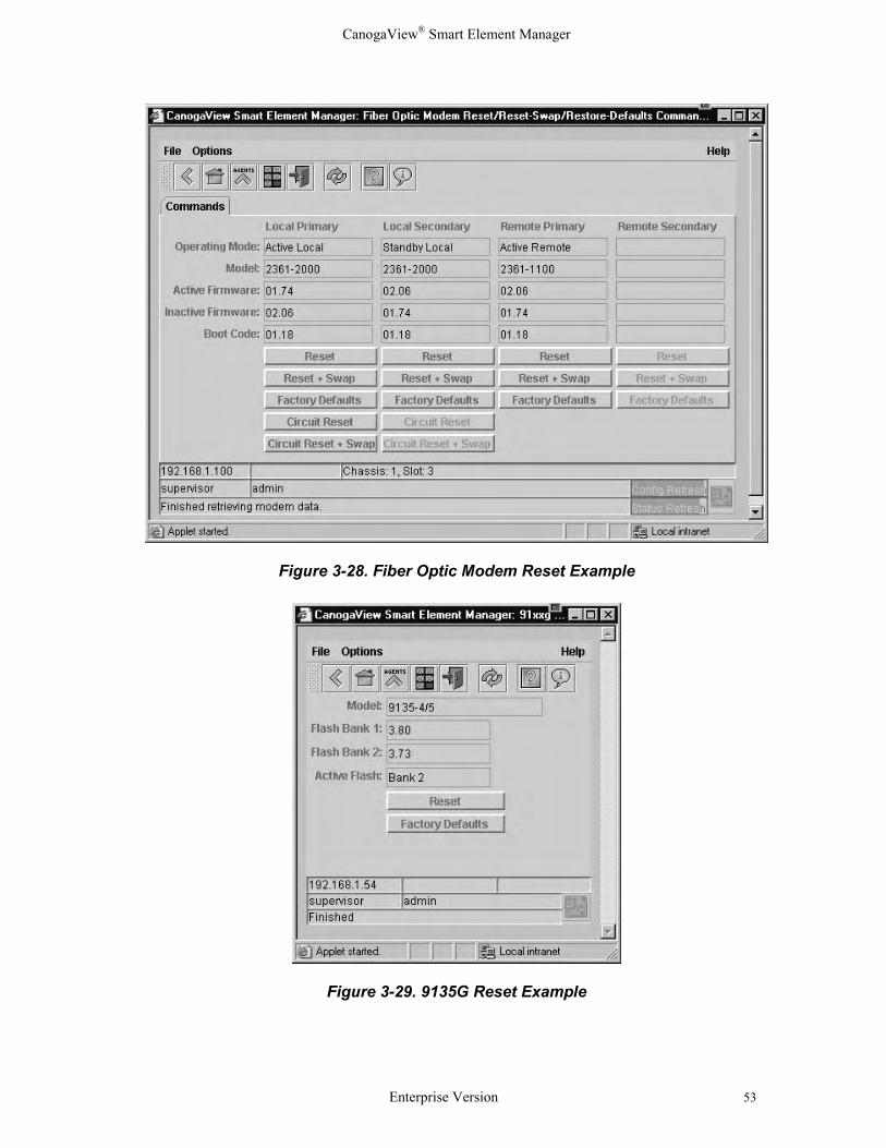
CanogaView Smart Element Manager supports the user in the setup and maintenance ofthe network by providing a set of Configuration Management features. Through the use ofspecialized configuration applications which retrieve configuration data directly from thedevice using SNMP, applications that allow the user to verify and edit parameters, resetdevices, download new code, generate reports or telnet to a device are provided.
• Configuration display and edit
• Craft Interface to Device using Telnet (see section 3.3.8)• Inventory Reports (see section 3.3.5)• TFTP based Code Download (see section 3.3.9)• Reset (see section 3.3.4)
An example of a 9135G Port Level Configuration application follows:
CanogaView® Smart Element Manager
52 Enterprise Version
Figure 3-27. 9135G Port Configuration
3.3.4 Reset
At various levels the user is able to issue reset commands to a device and its components.See the application chart in section 3.1.1 for details.
An example of a Fiber Optic Modem Reset application is displayed next. Note that the usercan Reset, Reset and Swap, restore the unit to Factory Defaults at a device or circuit level.In all cases, a confirmation message is displayed prior to command execution. Also, thereset of device may cause the unit to go off line or switch to a redundant circuit.
CanogaView® Smart Element Manager
Enterprise Version 53
Figure 3-28. Fiber Optic Modem Reset Example
Figure 3-29. 9135G Reset Example
CanogaView® Smart Element Manager
54 Enterprise Version
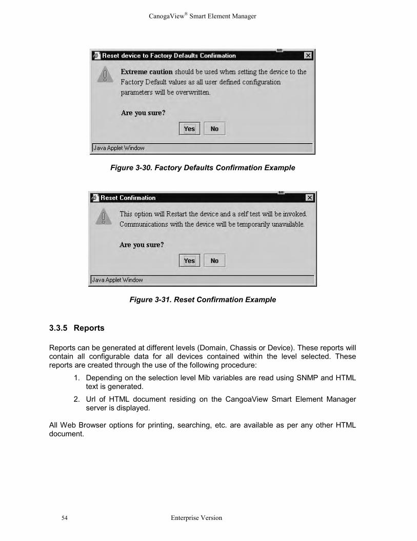
Figure 3-30. Factory Defaults Confirmation Example
Figure 3-31. Reset Confirmation Example
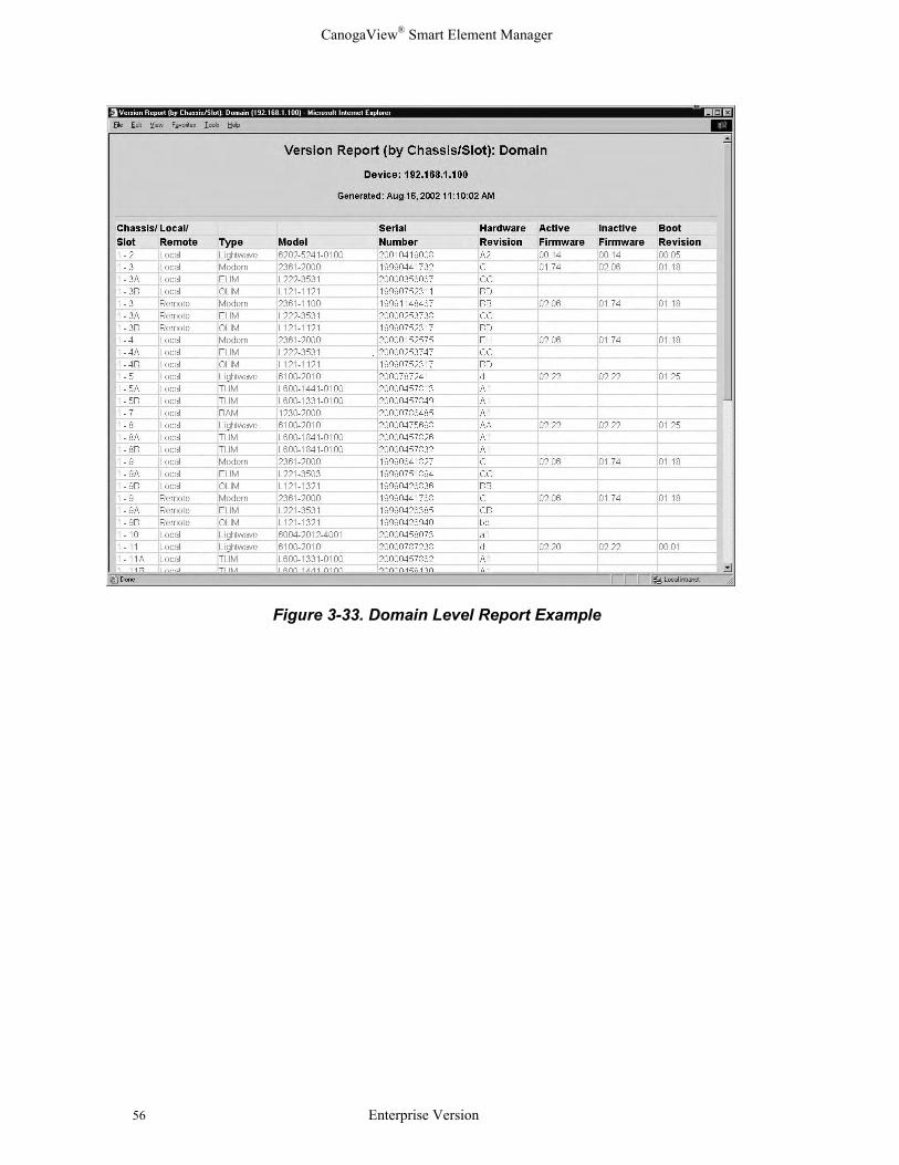
3.3.5 Reports
Reports can be generated at different levels (Domain, Chassis or Device). These reports willcontain all configurable data for all devices contained within the level selected. Thesereports are created through the use of the following procedure:
1. Depending on the selection level Mib variables are read using SNMP and HTMLtext is generated.
2. Url of HTML document residing on the CangoaView Smart Element Managerserver is displayed.
All Web Browser options for printing, searching, etc. are available as per any other HTMLdocument.

CanogaView® Smart Element Manager
Enterprise Version 55
Figure 3-32. Domain Level Reports
CanogaView® Smart Element Manager
56 Enterprise Version
Figure 3-33. Domain Level Report Example
CanogaView® Smart Element Manager
Enterprise Version 57
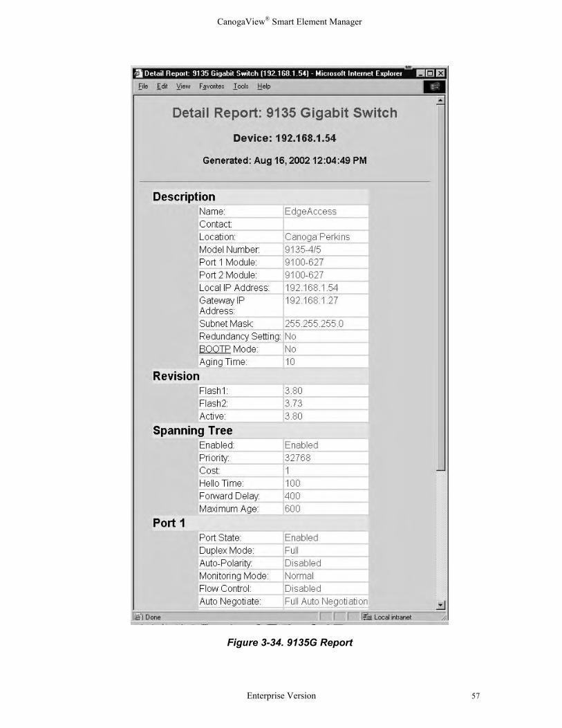
Figure 3-34. 9135G Report
CanogaView® Smart Element Manager
58 Enterprise Version
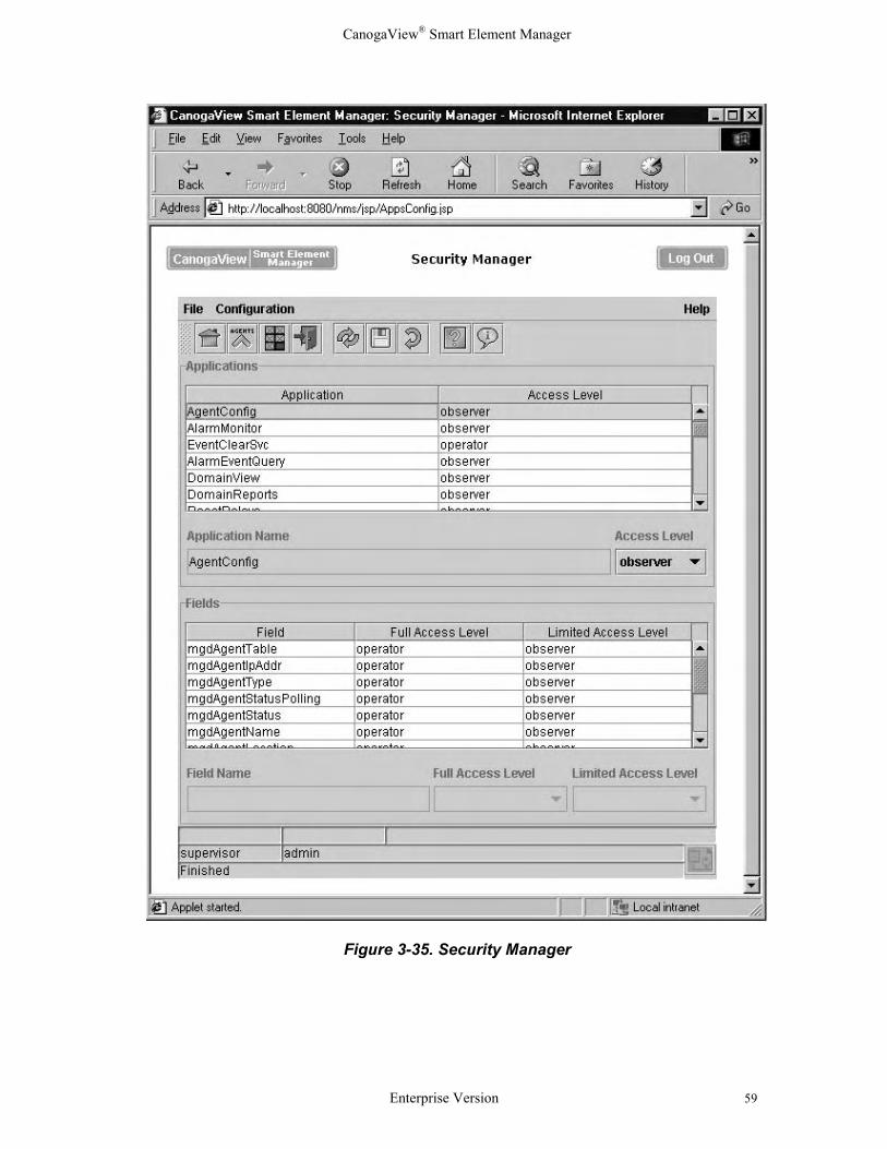
3.3.6 Security Manager
Collectively the security features within CanogaView Login, Application Level Security -(Administrator, Operator, Observer), SNMP Community Names, DMM (SNMP Proxy)Trusted Hosts and Server OS Login/Password support provide for a robust secured product.
To manage application security, open the Security Manager. On a Windows platform, thispage can be accessed from the Security Manager shortcut installed during the CanogaViewinstallation (see Figure 3-6. Shortcut Menu) or the Utilities option from the CanogaViewStart page (see Figure 3-8: CanogaView Start Page).
On a UNIX platform or remote windows platform, open the URL for the Security Manager asdocumented in Section 3.2.1 and 3.2.2.
http://canogaview_server_host:8080/nms/jsp/AppsConfig.jsp
Each application can have a minimum access level assigned which is required to open theapplication (e.g., if UsersConfig application is assigned a Supervisor level access, userswithout this security level will be denied access when attempting to configure the Usersdata.)
Individual fields within the application can also be assigned access levels; "full access,""limited access" and "none."
• Full Access - allows read/write privileges for users with the minimum access level (i.e.,observer, operator, supervisor)
• Limited Access - allows read only privileges for users with the minimum access level(i.e., observer, operator, supervisor)
• None - does not allow the field to be displayed or interacted with any user.
CanogaView® Smart Element Manager
Enterprise Version 59
Figure 3-35. Security Manager
CanogaView® Smart Element Manager
60 Enterprise Version
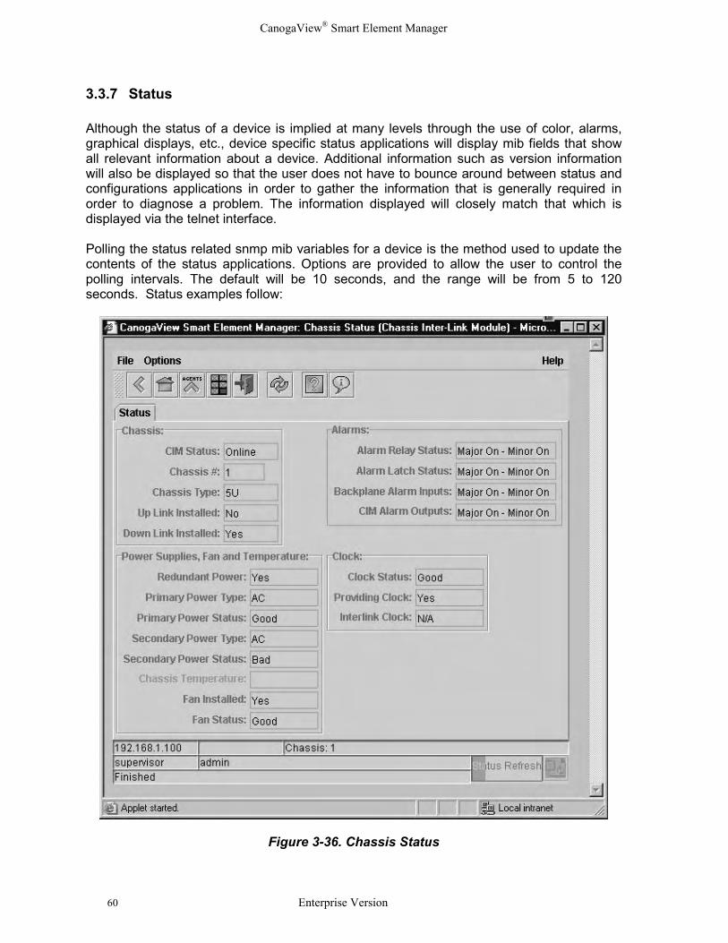
3.3.7 Status
Although the status of a device is implied at many levels through the use of color, alarms,graphical displays, etc., device specific status applications will display mib fields that showall relevant information about a device. Additional information such as version informationwill also be displayed so that the user does not have to bounce around between status andconfigurations applications in order to gather the information that is generally required inorder to diagnose a problem. The information displayed will closely match that which isdisplayed via the telnet interface.
Polling the status related snmp mib variables for a device is the method used to update thecontents of the status applications. Options are provided to allow the user to control thepolling intervals. The default will be 10 seconds, and the range will be from 5 to 120seconds. Status examples follow:
Figure 3-36. Chassis Status
CanogaView® Smart Element Manager
Enterprise Version 61
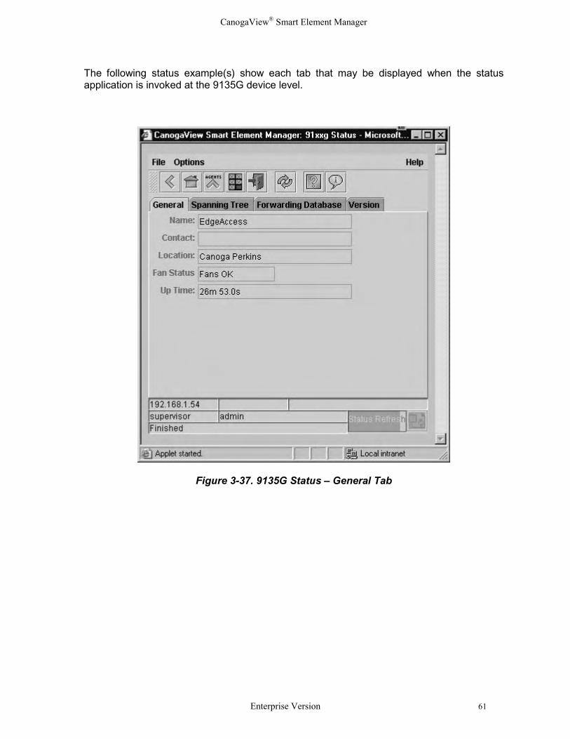
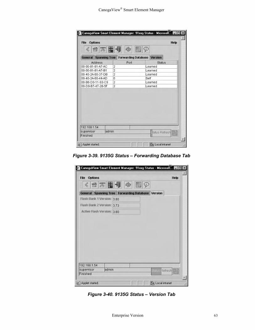
The following status example(s) show each tab that may be displayed when the statusapplication is invoked at the 9135G device level.
Figure 3-37. 9135G Status – General Tab
CanogaView® Smart Element Manager
62 Enterprise Version
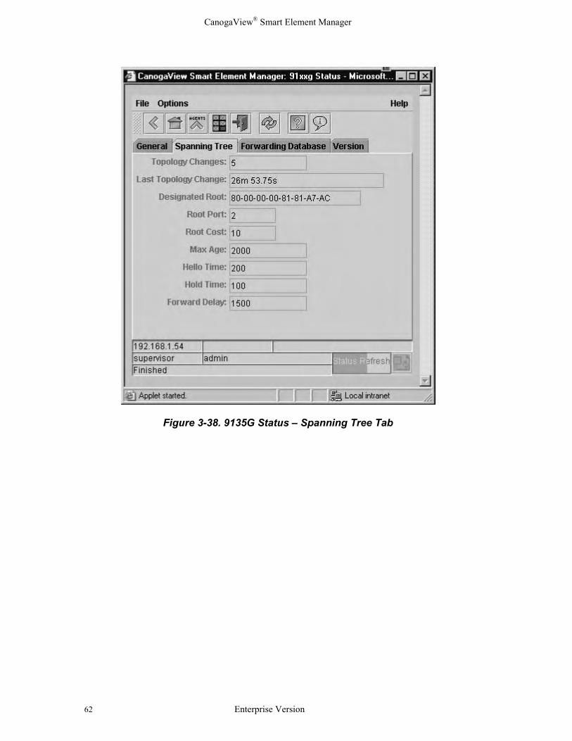
Figure 3-38. 9135G Status – Spanning Tree Tab
CanogaView® Smart Element Manager
Enterprise Version 63
Figure 3-39. 9135G Status – Forwarding Database Tab
Figure 3-40. 9135G Status – Version Tab
CanogaView® Smart Element Manager
64 Enterprise Version
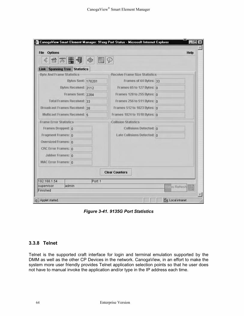
Figure 3-41. 9135G Port Statistics
3.3.8 Telnet
Telnet is the supported craft interface for login and terminal emulation supported by theDMM as well as the other CP Devices in the network. CanogaView, in an effort to make thesystem more user friendly provides Telnet application selection points so that he user doesnot have to manual invoke the application and/or type in the IP address each time.
CanogaView® Smart Element Manager
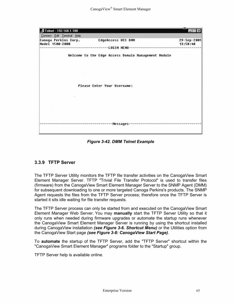
Enterprise Version 65
Figure 3-42. DMM Telnet Example
3.3.9 TFTP Server
The TFTP Server Utility monitors the TFTP file transfer activities on the CanogaView SmartElement Manager Server. TFTP "Trivial File Transfer Protocol" is used to transfer files(firmware) from the CanogaView Smart Element Manager Server to the SNMP Agent (DMM)for subsequent downloading to one or more targeted Canoga Perkins's products. The SNMPAgent requests the files from the TFTP Server process; therefore once the TFTP Server isstarted it sits idle waiting for file transfer requests.
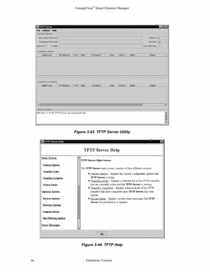
The TFTP Server process can only be started from and executed on the CanogaView SmartElement Manager Web Server. You may manually start the TFTP Server Utility so that itonly runs when needed during firmware upgrades or automate the startup runs wheneverthe CanogaView Smart Element Manager Server is running by using the shortcut installedduring CanogaView installation (see Figure 3-6. Shortcut Menu) or the Utilities option fromthe CanogaView Start page (see Figure 3-8: CanogaView Start Page).
To automate the startup of the TFTP Server, add the "TFTP Server" shortcut within the"CanogaView Smart Element Manager" programs folder to the "Startup" group.
TFTP Server help is available online.
CanogaView® Smart Element Manager
66 Enterprise Version
Figure 3-43. TFTP Server Utility
Figure 3-44. TFTP Help
CanogaView® Smart Element Manager
Enterprise Version 67
Chapter 4 Frequently Asked QuestionsThe following list of frequently asked questions is installed on the CanogaView SmartElement Manager Server under the Technical Support option.
4.1 What Web Server Platforms are supported?
The Enterprise Version of CanogaView Smart Element Manager supports the followingserver platforms:
• HP workstation running HP-UX version 11.0
• Sun workstation running Sun Solaris OS version 7 (a.k.a. Solaris 2.7, SunOS 5.7)
• PC workstation running Windows NT 4.0 SP4, Windows 2000 or XP.
4.2 What Web Client Platforms are supported?
Client access to the Enterprise Version can be performed on any of the following platforms:
• HP-UX - Netscape Navigator 4.75 with Java Plug-In 1.3.0_01
• Windows NT, 98 or 2000 - Netscape Navigator 4.06 -or- Microsoft Internet Explorer4.0, both with Java Plug-In 1.3.0_01
• Sun Solaris - Netscape Navigator 4.76 with Java Plug-In 1.3.0_01
• Linux - with Java Plug-In 1.3.0_01
4.3 What Web Server is used by CanogaView Smart Element Manager?
Tomcat 3.2. Refer to http://jakarta.apache.org/tomcat for more information.
4.4 What is a Java Plug-In or Java Runtime Environment?Java Plug-in software enables customers to run Java applets or on their web browser usingSun's Java 2 Runtime Environment, Standard Edition (JRE) instead of the web browser'sdefault virtual machine. Sun's JRE provides a Java Compatible environment for today'swidely adopted web browsers - that means consistency and reliability when running applets.
Refer to http://java.sun.com/products/plugin/ for more information.
4.5 How many Web Clients are supported?
By default, the Enterprise Version is installed with a one seat user license. This licenserestricts the support such that only one active client web session is allowed at a time. 10seat and unlimited seat upgrade options are available.
CanogaView® Smart Element Manager
68 Enterprise Version
4.6 How many User Accounts are supported?No limitation.
4.7 How do I Install CanogaView Smart Element Manager?Refer to the CanogaView Smart Element Manager manual and the Installation Notes forinstructions on how to Install CanogaView Smart Element Manager. The manual is availablein hardcopy or at www.canoga.com. The Notes are available in hardcopy, on the installationCD, at http://localhost:8080/nms/html/read_win.txt.or at www.canoga.com.
4.8 How do I Uninstall CanogaView Smart Element Manager?Refer to the Installation Notes for instructions on how to Uninstall CanogaView SmartElement Manager. The Notes are available in hardcopy, on the installation CD, athttp://localhost:8080/nms/html/read_win.txt.or at www.canoga.com.
4.9 How do I Login?Two user accounts are installed with the system: "guest" and "admin" with passwords"guest" and "admin" respectively. The "guest" user is assigned "observer" access and the"admin" user is assigned "supervisor" access.
It is suggested that the Administrator change these passwords to prevent unauthorizedaccess.
For security reasons, this version of CanogaView Smart Element Manager willadministratively "lock out" any user account after the third consecutive unsuccessful loginattempt. The locked out account may be re-enabled via the Account Manager applet. In thecase that the Administrator himself has been locked out, contact CanogaView SmartElement Manager Technical Support for a resolution.
4.10 Why doesn't CanogaView Smart Element Manager supportNetscape 6.0?Netscape 6 does not support LiveConnect which CanogaView Smart Element Manageruses to communicate between its applets and the web browser pages. This restrictsCanogaView Smart Element Manager from opening a new browser window from within itsapplets, ability to handle the items such as "Close Other Windows" or bringing an existingwindow to the foreground. Until Netscape 6 supports this feature, which Netscape 4.Xsupports, CanogaView Smart Element Manager will not be able to support Netscape 6.
This is from the Netscape 6 release notes athttp://home.netscape.com/eng/mozilla/ns6/relnotes/6.0.html#new : LiveConnect is not yetenabled in this release. LiveConnect and LiveConnect security will be enabled in a laterrelease.
CanogaView® Smart Element Manager
Enterprise Version 69
Netscape 6.2 with Java Plug-in 1.3.1 or later works correctly.
4.11 What Version of HP OpenView can CanogaView Smart ElementManager be integrated with?
HP OpenView Network Node Manager 6.1. Refer to the platform specific read me files forHP NNM patch information.
4.12 What does CanogaView Smart Element Manager actually do?The CanogaView Smart Element Manager Server is basically responsible for the followingmajor features:
o provides Web Server facilities for the CanogaView Smart Element ManagerWeb Clients
o storage and management of the CanogaView Smart Element Managerapplications and databases
o SNMP support to Canoga Perkins SNMP Agents
o Tftp Download facilities for device upgrade support
As all CanogaView Smart Element Manager applets execute within a Web Browser (eitherNetscape or Internet Explorer), the browser must be capable of supporting the Java Plug-In.
4.13 Which Canoga Perkin's Products does CanogaView Smart ElementManager manage?Presently support is provided for the UCS 2U and 5U Chassis and all of their respectivedevices as well as the LAN Extension 9135/40 and 9135 Gigabit products and theircomponents.
4.14 What versions of the products must be installed?Refer to Canoga Perkin's web site for product specific firmware available for the most up-to-date information.
4.15 What is a Domain?In the context of the UCS 2U and 5U chassis; a domain is a set of products installed within agroup of chassis (maximum 8) which are managed by a single DMM device (SNMP Agent).Each chassis has 16 slots and chassis are connected via a CIM card and cable.Additionally, remote devices which can be accessed via side-band management can also bemanaged.
CanogaView® Smart Element Manager
70 Enterprise Version
4.16 How are Remote Products managed?Remote products are managed via a side-band management channel.
4.17 What Security Levels does CanogaView Smart Element Managersupport?The 3 levels of security are Supervisor, Operator and Observer. By default, CanogaViewSmart Element Manager is installed using the following premises:
o Users with Supervisor access perform administrative functions such as thesetup of user accounts and security customization, along with all featureswithin all applications.
o Users with Operator access can execute all features within all of theapplications including the resetting of units, running diagnostics, configurationchanges, etc. but they are restricted from using administrative functions.
o User with Observer access can execute all applications like that of anOperator, but their is Read-Only in that they cannot reset units, rundiagnostic procedures, clear status counters, etc.
CanogaView® Smart Element Manager
Enterprise Version 71
Chapter 5 TroubleshootingThe following is a list of typical troubleshooting techniques that can be used to determineand correct a problem.
5.1 No Response from SNMP AgentIf the applications are showing the error "No Response from SNMP Agent", verify thefollowing:
1. That the CanogaView Smart Element Manager Web Server's address isentered into the SNMP Agent's (DMM's or 9135/40, etc.) host table. TheSNMP agents will only respond to those IP addresses listed in its host table.
2. That the Agent's Default Gateway field is set correctly. A correct DefaultGateway is required in a routed environment to ensure that IP connectivity ispossible from the SNMP Agent to the CanogaView Smart Element ManagerWeb Server.
3. That you can Ping the SNMP Agent from the CanogaView Smart ElementManager Web Server and vice versa.
4. That you can Telnet to the SNMP Agent from the CanogaView SmartElement Manager Web Server.
5. From the CanogaView Smart Element Manager Web Server, try runningrunning traceroute to trace the route from the CanogaView Smart ElementManager Web Server to the SNMP Agent. Failures can indicate a problemwith a router setup or the Default Gateway setting on the Agent.
6. Verify the correct SNMP Community names are being used within the AgentChooser and match those in the SNMP Agent's System Configurationparameters.
7. If you have access to a SNMP Mib Browser software, see if you can accessthe SNMP Agent.
8. If you have access to a protocol analyzer, monitor the connection to see ifany SNMP traffic is present for these IP addresses.
9. Try resetting the SNMP Agent.
10. Contact Technical Support.
5.2 "Model Not Found" image appears on my ViewThis image appears when CanogaView Smart Element Manager is unable to find a matchbetween the model number reported by the device to an image file located at theCanogaView Smart Element Manager server. Verify the model number reported by thedevice by telneting to the device or placing the cursor over the image from which the tooltipwill display the model number.

CanogaView® Smart Element Manager
72 Enterprise Version
Contact technical support with this information for a resolution.
5.3 Traps/Alarm ProcessingIf you are experiencing problems receiving alarms in the Alarm Monitor, there are severalthings you can do to troubleshoot the problem:
1. Make sure that the IP address of the CanogaView Smart Element Manager servercomputer is listed in the Host Table of the SNMP Agent from which alarms are expected,and that the Access Level for this IP address is "4" (Read/Write/Trap).
Example DMM instructions: To do this, start a Telnet session to the DMM. On theMAIN MENU, select "1" to access the Domain Management Module. On the DOMAINMANAGEMENT MODULE screen, select "6" to view the Host Table. Add or edit an IPaddress entry for the CanogaView Smart Element Manager server as needed.
2. Verify that you have IP connectivity from the SNMP Agent to the CanogaView SmartElement Manager server by pinging the server from the device.
Example DMM instructions: Start a Telnet session to the DMM. On the MAIN MENU,select "1" to access the Domain Management Module. On the DOMAINMANAGEMENT MODULE screen, select "3", Ping Generation. On the PING MENUscreen, enter the IP address of the CanogaView Smart Element Manager servercomputer and a number of ping attempts to make. Hit Enter to start the test. If ping requests are sent but not received, it indicates a lack of IP connectivity from theSNMP Agent to the server. In this case, it is not possible for CanogaView SmartElement Manager to receive SNMP traps from the SNMP Agent. Contact your systemor network administrator for help with troubleshooting a network problem.
3. Verify that the CanogaView Smart Element Manager services needed for trapprocessing are running, and stop/restart them if necessary. Windows NT/2000 Open the Services application (Start->Settings->Control Panel: Services) and look forthe "CanogaView Smart Element Manager" service. The status of this service should be"Started"; if it is not, select the "CanogaView Smart Element Manager" list item andclick the Start button.
If after troubleshooting alarms are still not being received, you can try to stop and restartthe services by selecting the "CanogaView Smart Element Manager" service list item,clicking on "Stop", then "Start".
4. Determine if SNMP traps sent by the SNMP Agent are arriving at the CanogaView Smart
Element Manager server computer by looking at syslog messages. On Windows NT/2000, execute the following program to display syslog messages:
nms-install-directory\syslogd\2.2\syslogd-2.2\application\SyslogD.exe
CanogaView® Smart Element Manager
Enterprise Version 73
For each trap received, you should see messages from "TRAPSERVICE" and"EVENTENGINE".
5. Make sure that the CanogaView Smart Element Manager Trap Service is listening forSNMP traps on the correct port. The Trap Service listens for SNMP traps on the port number specified during theinstallation; this should be port 163 for computers that have HP's Network NodeManager or other network management packages installed, and port 162 otherwise. Ifconfigured incorrectly, Trap Service will either fail to start or will not process any traps. You can verify the configured port number by opening the service.conf file in yourCanogaView Smart Element Manager installation directory with a text editor. Thenumber following the string "-trapport" is the port number. If this number is incorrect,change it, save the change, and stop/restart the CanogaView Smart Element Managerservices as documented above.

CanogaView® Smart Element Manager
74 Enterprise Version
CanogaView® Smart Element Manager
Enterprise Version 75
Appendix AWarranty
Limited Lifetime WarrantyEffective for Products Shipped February 1, 2003 and After, Canoga Perkins warrants that, at the time ofsale, and, for its lifetime, with certain exceptions noted below, every Canoga Perkins' labeled product purchasedwill be free from defects in material and workmanship for its lifetime, if properly installed and used inconformity to Canoga Perkins' published specifications. This warranty covers the original user only and is nottransferable. For the purposes of this Warranty, "lifetime" is defined as the serviceable life of the product (aminimum of 5 years) or any longer period during which replacement spare parts are available. Subject to theconditions and limitations set forth below, Canoga Perkins will, at its option, either repair or replace any part ofits product(s) that prove defective by reason of improper workmanship or materials. The warranty period forpower supplies, fans and optics is five (5) years. Consumables such as filters are covered for one year. Softwareis warranted for 90 days.
This warranty does not cover any damage to products that have been subjected to lightning damage or otherActs of Nature, misuse, neglect, accident, damage, improper installation, or maintenance, including over-voltage failures caused by use outside of the product's specified rating, normal wear and tear of mechanicalcomponents, or alteration or repair by anyone other than Canoga Perkins or its authorized representative. If theuser is unsure about the proper means of installing or using the equipment, contact Canoga Perkins' freetechnical support services. Customer must notify Canoga Perkins promptly in writing of any claim based onwarranty. Canoga Perkins is not liable for, and does not cover under warranty, any costs associated withservicing and/or the installation of its products of for any inspection, packing or labor costs in connection withreturn of goods. In the event Canoga Perkins breaches its obligation of warranty, customer's sole and exclusiveremedy is limited to replacement, repair, or credit of the purchase price, at Canoga Perkins' option. Under nocircumstance will Canoga Perkins be liable for consequential or incidental damages or loss of profits.
Warranty RegistrationTo establish original ownership and to record purchase date, please complete the warranty on-line form on ourproduct registration page. URL: www.canoga.com/warranty
Optional Service ProgramsCanoga Perkins offers several optional Service Programs. Please call Canoga Perkins Sales Department (818-718-6300) or see our web site (www.canoga.com) for details.
CUSTOMER SERVICE DEPARTMENT REPAIR WARRANTYRepairs performed by the Canoga Perkins Customer Service Department will be free from defects in materialand workmanship for a period of ninety (90) DAYS from the date the repaired product is shipped, or until theexpiration of the original factory warranty, whichever is longer.
CanogaView® Smart Element Manager
76 Enterprise Version
LimitationsCanoga Perkins may at its sole discretion modify its Limited Warranty at any time and from time to time.
Other than those expressly stated herein, THERE ARE NO OTHER WARRANTIES OF ANY KIND,EXPRESSED OR IMPLIED, AND SPECIFICALLY EXCLUDED BUT NOT BY WAY OF LIMITATION,ARE THE IMPLIED WARRANTIES FOR FITNESS FOR A PARTICULAR PURPOSE ANDMERCHANTABILITY. IT IS UNDERSTOOD AND AGREED CANOGA PERKINS' LIABILITYWHETHER IN CONTRACT, IN TORT, UNDER ANY WARRANTY, IN NEGLIGENCE OR OTHERWISESHALL NOT EXCEED THE AMOUNT OF THE PURCHASE PRICE PAID BY THE CUSTOMER ANDUNDER NO CIRCUMSTANCES SHALL CANOGA PERKINS BE LIABLE FOR SPECIAL, INDIRECT,INCIDENTAL OR CONSEQUENTIAL DAMAGES. THE PRICE STATED FOR THE EQUIPMENT IS ACONSIDERATION IN LIMITING CANOGA PERKINS' LIABILITY. NO ACTION, REGARDLESS OFFORM, ARISING OUT OF THE TRANSACTIONS OF THIS AGREEMENT MAY BE BROUGHT BYCUSTOMER MORE THAN ONE YEAR AFTER THE CAUSE OF THE ACTION HAS ACCRUED.CANOGA PERKINS' MAXIMUM LIABILITY SHALL NOT EXCEED AND CUSTOMER'S REMEDY ISLIMITED TO EITHER (i) REPAIR OR REPLACEMENT OF THE DEFECTIVE PART OF PRODUCT, ORAT CANOGA PERKINS' OPTION (ii) RETURN OF THE PRODUCT AND REFUND OF THE PURCHASEPRICE, AND SUCH REMEDY SHALL BE CUSTOMER'S ENTIRE AND EXCLUSIVE REMEDY.AUTHORIZED RESELLERS ARE NOT AUTHORIZED TO EXTEND ANY DIFFERENT WARRANTYON CANOGA PERKINS' BEHALF.
Return PolicyCustomer must obtain an RMA (Return Material Authorization) number from the Canoga Perkins CustomerService Department before returning a product for service or repair.
Canoga Perkins' technical support department can be reached through any of the following means:
Telephone: 818-718-6300Fax: 818-718-6312E-Mail: [email protected]
If the warranty for a power supply, fan, optics, consumable or software has expired, customer must provide theCanoga Perkins Customer Service Representative with a Purchase Order to authorize the repair.
Send the defective product postage and insurance prepaid to the address provided to you by Canoga Perkins'technical support representative. Failure to properly protect the product during shipping may void this warranty.The return authorization number must be written on the outside of the carton to ensure its acceptance.
The customer must pay for the non-compliant product(s) return transportation costs to Canoga Perkins forevaluation of said product(s) for repair or replacement. Canoga Perkins will pay for the shipping of the repairedor replaced in-warranty product(s) back to the customer (any and all customs charges, tariffs, or/and taxes arethe customer's responsibility).
Canoga Perkins reserves the right to charge for all testing and shipping incurred, if after testing, a return isclassified as "No Problem Found."

CANOGA PERKINS CORPORATION20600 Prairie Street
Chatsworth, California 91311-6008 USAPhone: (818) 718-6300 FAX: (818) 718-6312
Web Site: www.canoga.comEmail: [email protected]