Embed Size (px)
Citation preview
© 2009 Cisco Systems, Inc. All rights reserved. Cisco PublicPresentation_ID 1
Steve AckerWireless Network Consulting EngineerCCIE #14097CISSP #86844
Enterprise WLAN Architecture
© 2008 Cisco Systems, Inc. All rights reserved. Cisco Public 2BRKAGG-2010
Presentation_ID
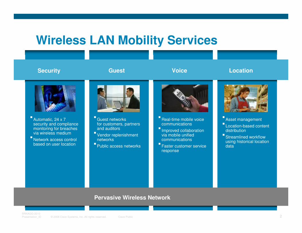
Wireless LAN Mobility Services
Security Guest Voice Location
�Guest networks for customers, partners and auditors
�Vendor replenishment networks
�Public access networks
�Automatic, 24 x 7 security and compliance monitoring for breaches via wireless medium
�Network access control based on user location
�Asset management�Location-based content
distribution�Streamlined workflow
using historical location data
�Real-time mobile voice communications
� Improved collaboration via mobile unified communications
�Faster customer service response
Pervasive Wireless Network
© 2008 Cisco Systems, Inc. All rights reserved. Cisco Public 3BRKAGG-2010
Presentation_ID
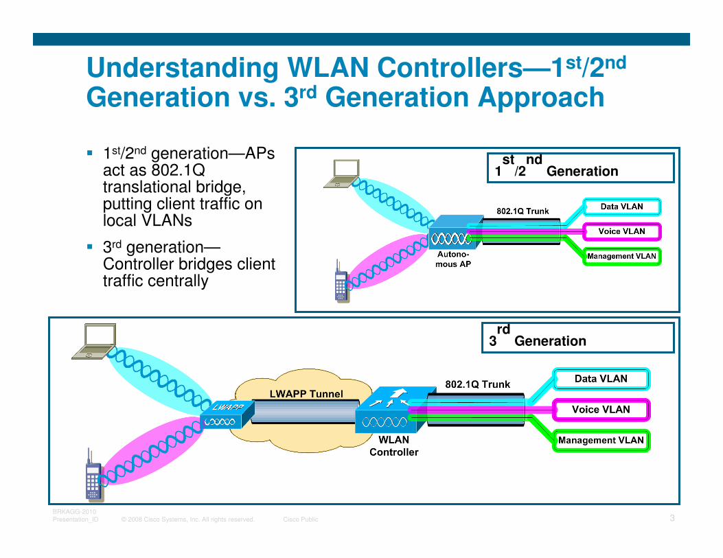
Understanding WLAN Controllers—1st/2nd
Generation vs. 3rd Generation Approach
� 1st/2nd generation—APs act as 802.1Q translational bridge, putting client traffic on local VLANs
� 3rd generation—Controller bridges client traffic centrally
1st
/2nd
Generation
3rd
Generation
© 2008 Cisco Systems, Inc. All rights reserved. Cisco Public 4BRKAGG-2010
Presentation_ID
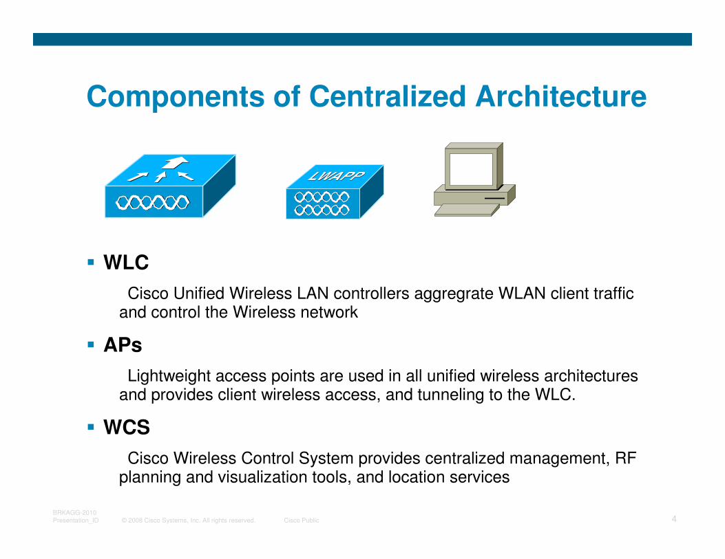
Components of Centralized Architecture
� WLC
Cisco Unified Wireless LAN controllers aggregrate WLAN client traffic and control the Wireless network
� APs
Lightweight access points are used in all unified wireless architectures and provides client wireless access, and tunneling to the WLC.
� WCS
Cisco Wireless Control System provides centralized management, RF planning and visualization tools, and location services
© 2008 Cisco Systems, Inc. All rights reserved. Cisco Public 5BRKAGG-2010
Presentation_ID
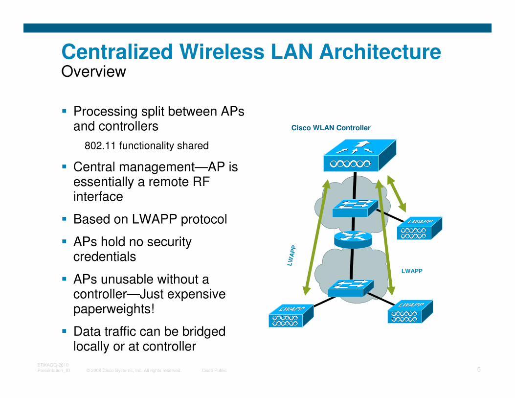
Centralized Wireless LAN ArchitectureOverview
� Processing split between APs and controllers
802.11 functionality shared
� Central management—AP is essentially a remote RF interface
� Based on LWAPP protocol
� APs hold no security credentials
� APs unusable without a controller—Just expensive paperweights!
� Data traffic can be bridged locally or at controller
Cisco WLAN Controller
LWAPP
LW
AP
P
© 2008 Cisco Systems, Inc. All rights reserved. Cisco Public 6BRKAGG-2010
Presentation_ID
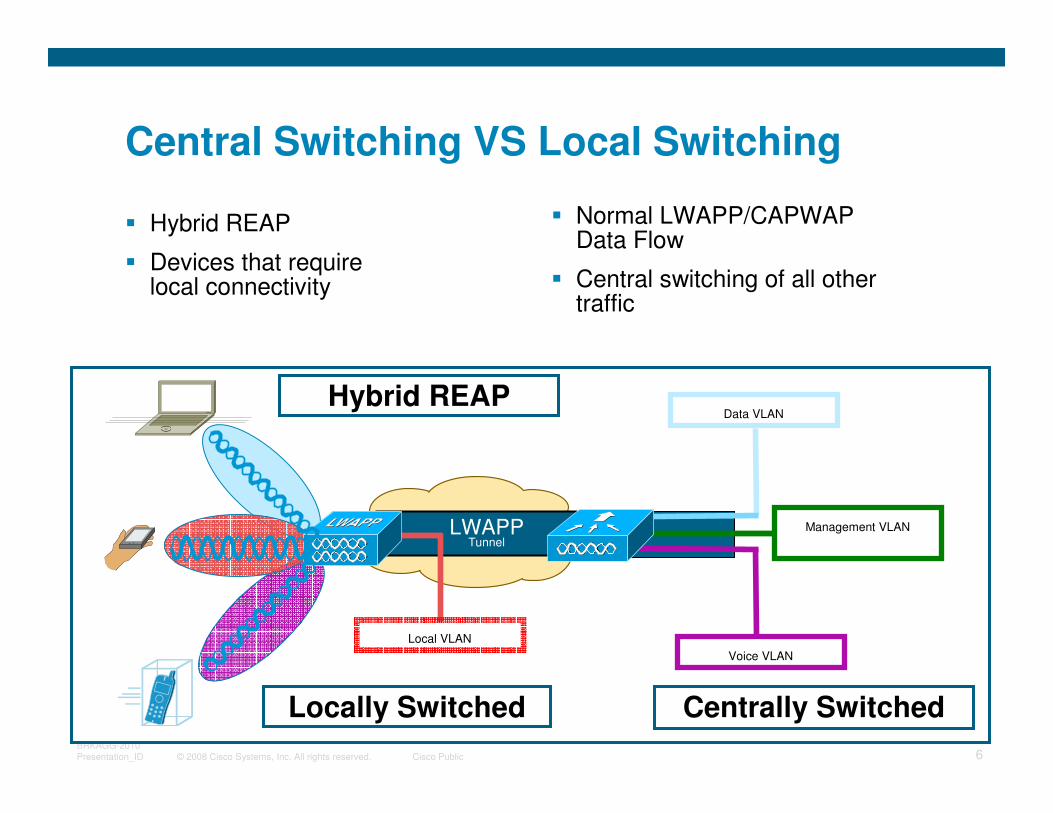
Central Switching VS Local Switching
� Hybrid REAP
� Devices that require local connectivity
Hybrid REAP
� Normal LWAPP/CAPWAP Data Flow
� Central switching of all other traffic
Data VLAN
Voice VLAN
Management VLAN
Local VLAN
LWAPPTunnel
Centrally SwitchedLocally Switched
© 2008 Cisco Systems, Inc. All rights reserved. Cisco Public 7BRKAGG-2010
Presentation_ID
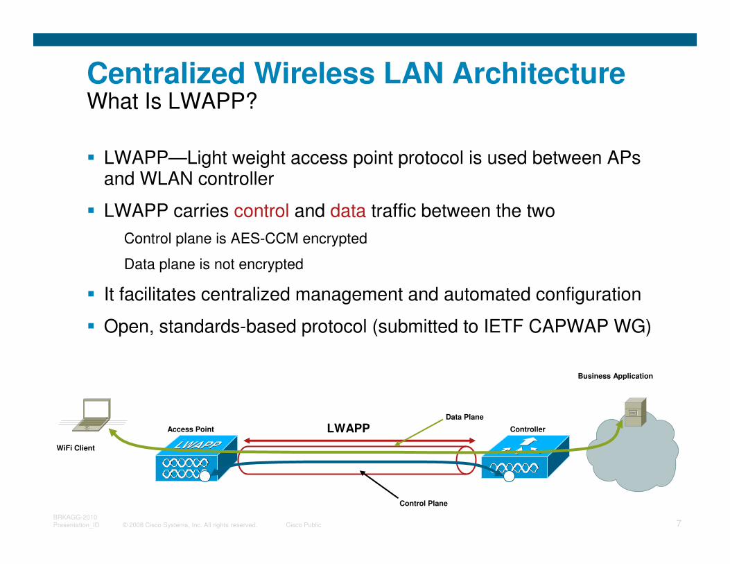
LWAPP
Centralized Wireless LAN ArchitectureWhat Is LWAPP?
� LWAPP—Light weight access point protocol is used between APs and WLAN controller
� LWAPP carries control and data traffic between the two
Control plane is AES-CCM encrypted
Data plane is not encrypted
� It facilitates centralized management and automated configuration
� Open, standards-based protocol (submitted to IETF CAPWAP WG)
Access Point Controller
WiFi Client
Business Application
Control Plane
Data Plane
© 2008 Cisco Systems, Inc. All rights reserved. Cisco Public 8BRKAGG-2010
Presentation_ID
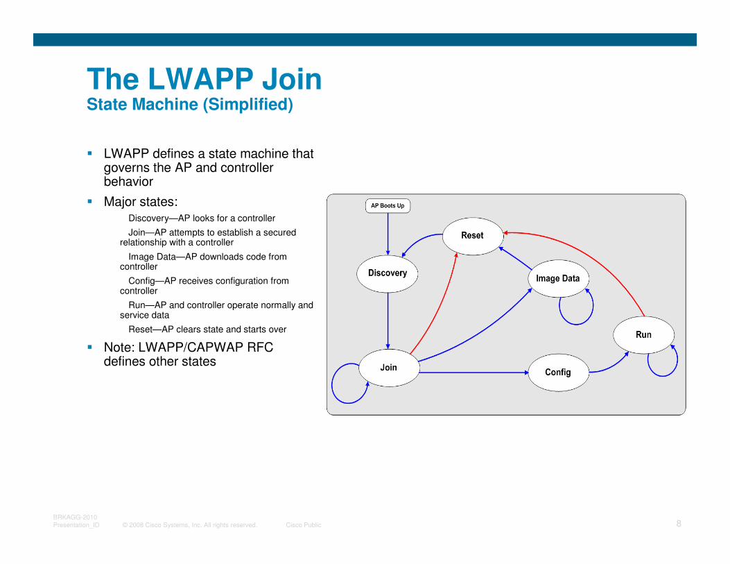
The LWAPP JoinState Machine (Simplified)
� LWAPP defines a state machine that governs the AP and controller behavior
� Major states:Discovery—AP looks for a controller
Join—AP attempts to establish a secured relationship with a controller
Image Data—AP downloads code from controller
Config—AP receives configuration from controller
Run—AP and controller operate normally and service data
Reset—AP clears state and starts over
� Note: LWAPP/CAPWAP RFC defines other states
© 2008 Cisco Systems, Inc. All rights reserved. Cisco Public 9BRKAGG-2010
Presentation_ID
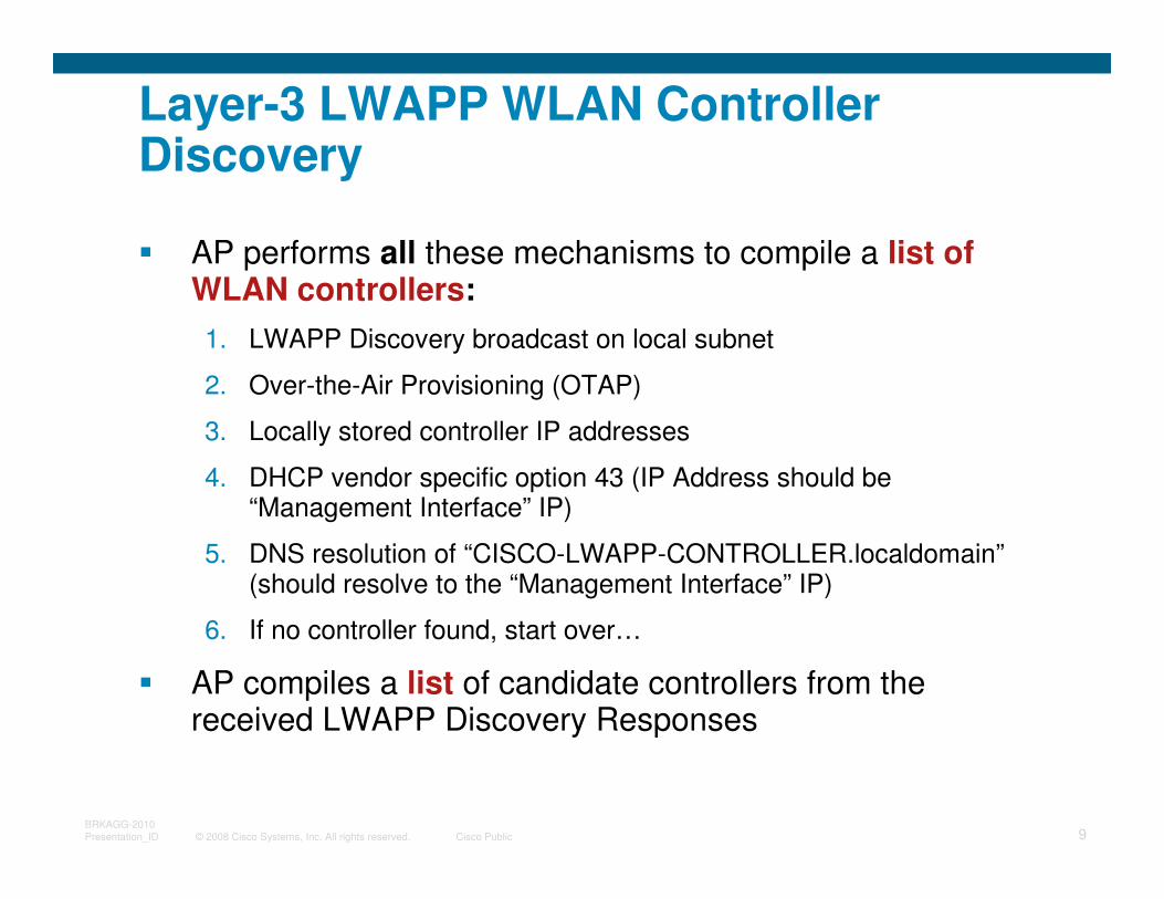
Layer-3 LWAPP WLAN Controller Discovery
� AP performs all these mechanisms to compile a list of WLAN controllers:
1. LWAPP Discovery broadcast on local subnet
2. Over-the-Air Provisioning (OTAP)
3. Locally stored controller IP addresses
4. DHCP vendor specific option 43 (IP Address should be “Management Interface” IP)
5. DNS resolution of “CISCO-LWAPP-CONTROLLER.localdomain”(should resolve to the “Management Interface” IP)
6. If no controller found, start over…
� AP compiles a list of candidate controllers from the received LWAPP Discovery Responses
© 2008 Cisco Systems, Inc. All rights reserved. Cisco Public 10BRKAGG-2010
Presentation_ID
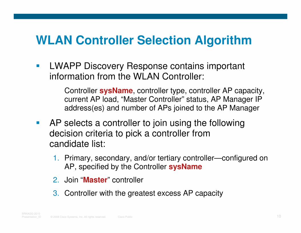
WLAN Controller Selection Algorithm
� LWAPP Discovery Response contains important information from the WLAN Controller:
Controller sysName, controller type, controller AP capacity, current AP load, “Master Controller” status, AP Manager IP address(es) and number of APs joined to the AP Manager
� AP selects a controller to join using the following decision criteria to pick a controller from candidate list:
1. Primary, secondary, and/or tertiary controller—configured on AP, specified by the Controller sysName
2. Join “Master” controller
3. Controller with the greatest excess AP capacity
© 2008 Cisco Systems, Inc. All rights reserved. Cisco Public 11BRKAGG-2010
Presentation_ID
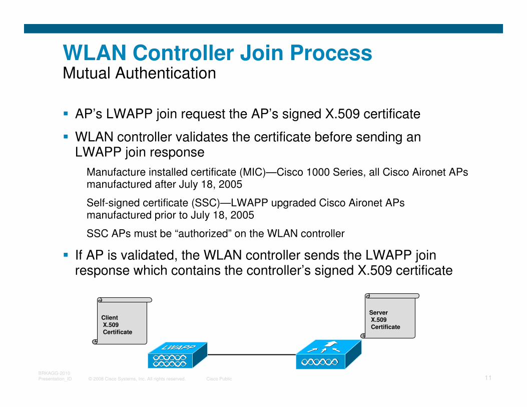
WLAN Controller Join ProcessMutual Authentication
� AP’s LWAPP join request the AP’s signed X.509 certificate
� WLAN controller validates the certificate before sending an LWAPP join response
Manufacture installed certificate (MIC)—Cisco 1000 Series, all Cisco Aironet APs manufactured after July 18, 2005
Self-signed certificate (SSC)—LWAPP upgraded Cisco Aironet APs manufactured prior to July 18, 2005
SSC APs must be “authorized” on the WLAN controller
� If AP is validated, the WLAN controller sends the LWAPP join response which contains the controller’s signed X.509 certificate
ClientX.509Certificate
ServerX.509Certificate
© 2008 Cisco Systems, Inc. All rights reserved. Cisco Public 12BRKAGG-2010
Presentation_ID
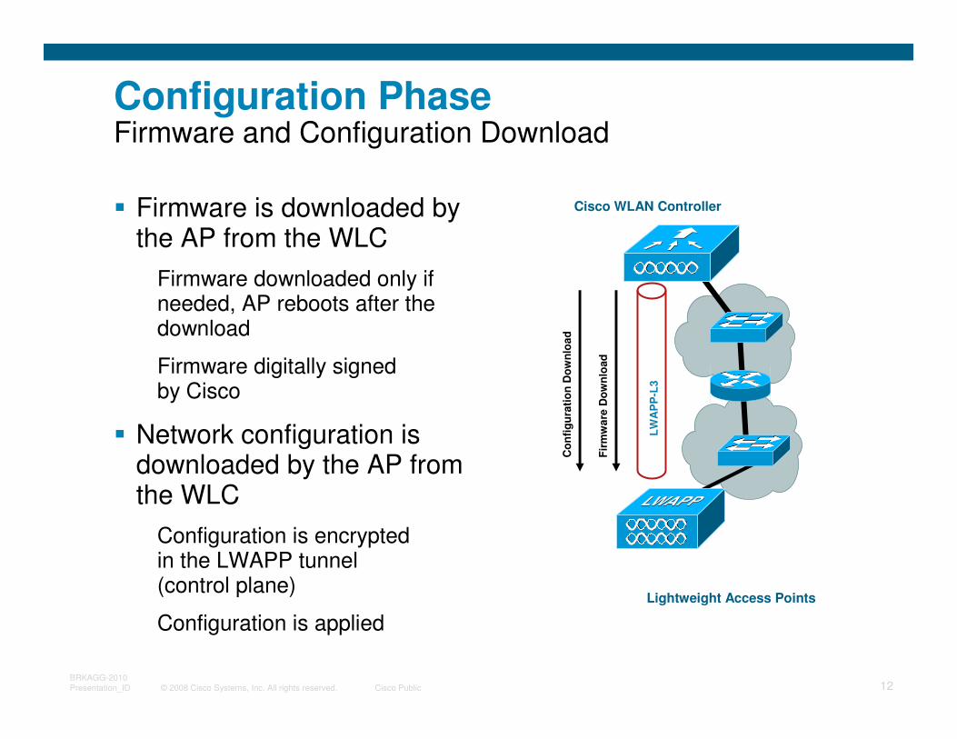
Configuration PhaseFirmware and Configuration Download
� Firmware is downloaded by the AP from the WLC
Firmware downloaded only if needed, AP reboots after the download
Firmware digitally signed by Cisco
� Network configuration is downloaded by the AP from the WLC
Configuration is encrypted in the LWAPP tunnel (control plane)
Configuration is applied
Lightweight Access Points
Cisco WLAN Controller
LW
AP
P-L
3
Fir
mw
are
Do
wn
load
Co
nfi
gu
rati
on
Do
wn
loa
d
© 2008 Cisco Systems, Inc. All rights reserved. Cisco Public 13BRKAGG-2010
Presentation_ID
Mobility Defined
� Mobility is the “killer app” for WLANs
� Mobility—end-user device is portable but still capable of being connected to networked resources
� Roaming occurs when a wireless client moves association from one AP and re-associates to another
� Mobility/roaming presents new challenges:
Architecture must scale to support client roaming
Client roaming must be fast and preserve security, QoS, etc.
© 2008 Cisco Systems, Inc. All rights reserved. Cisco Public 14BRKAGG-2010
Presentation_ID
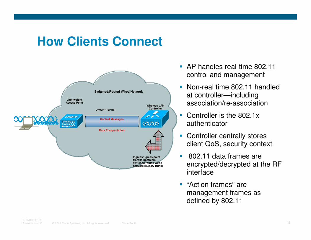
How Clients Connect
� AP handles real-time 802.11 control and management
� Non-real time 802.11 handled at controller—including association/re-association
� Controller is the 802.1x authenticator
� Controller centrally stores client QoS, security context
� 802.11 data frames are encrypted/decrypted at the RF interface
� “Action frames” are management frames as defined by 802.11
LWAPP Tunnel
Ingress/Egress point from/to upstream switched/routed wired network (802.1Q trunk)
Switched/Routed Wired Network
Lightweight Access Point
Wireless LAN Controller
Control Messages
Data Encapsulation
© 2008 Cisco Systems, Inc. All rights reserved. Cisco Public 15BRKAGG-2010
Presentation_ID
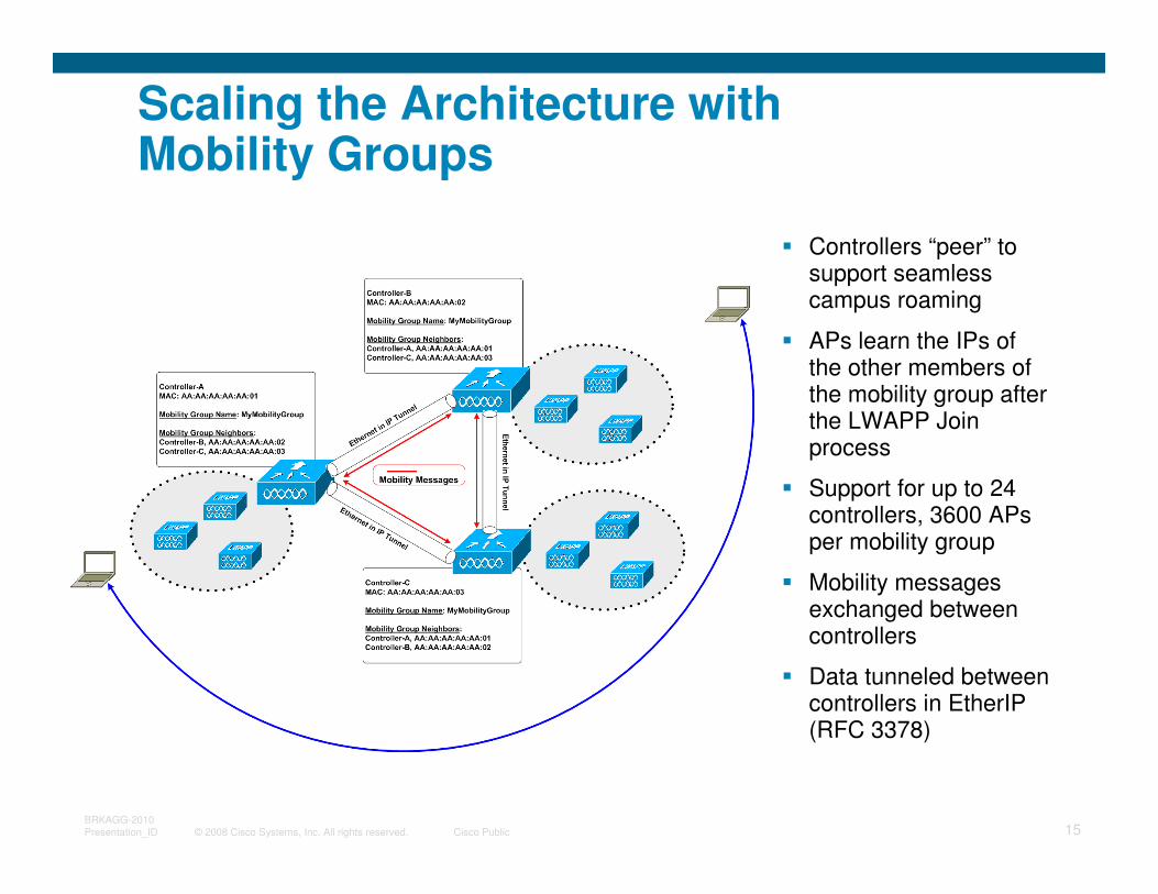
Scaling the Architecture with Mobility Groups
� Controllers “peer” to support seamless campus roaming
� APs learn the IPs of the other members of the mobility group after the LWAPP Join process
� Support for up to 24 controllers, 3600 APs per mobility group
� Mobility messages exchanged between controllers
� Data tunneled between controllers in EtherIP (RFC 3378)
© 2008 Cisco Systems, Inc. All rights reserved. Cisco Public 16BRKAGG-2010
Presentation_ID
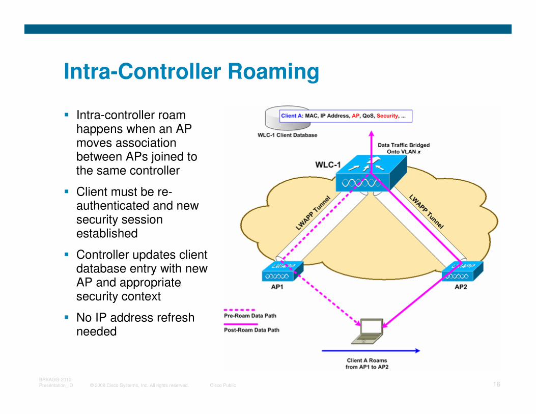
Intra-Controller Roaming
� Intra-controller roam happens when an AP moves association between APs joined to the same controller
� Client must be re-authenticated and new security session established
� Controller updates client database entry with new AP and appropriate security context
� No IP address refresh needed
© 2008 Cisco Systems, Inc. All rights reserved. Cisco Public 17BRKAGG-2010
Presentation_ID
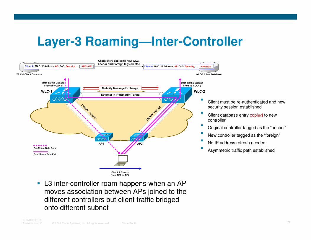
Layer-3 Roaming—Inter-Controller
� L3 inter-controller roam happens when an AP moves association between APs joined to the different controllers but client traffic bridged onto different subnet
� Client must be re-authenticated and new security session established
� Client database entry copied to new controller
� Original controller tagged as the “anchor”
� New controller tagged as the “foreign”
� No IP address refresh needed
� Asymmetric traffic path established
© 2008 Cisco Systems, Inc. All rights reserved. Cisco Public 18BRKAGG-2010
Presentation_ID
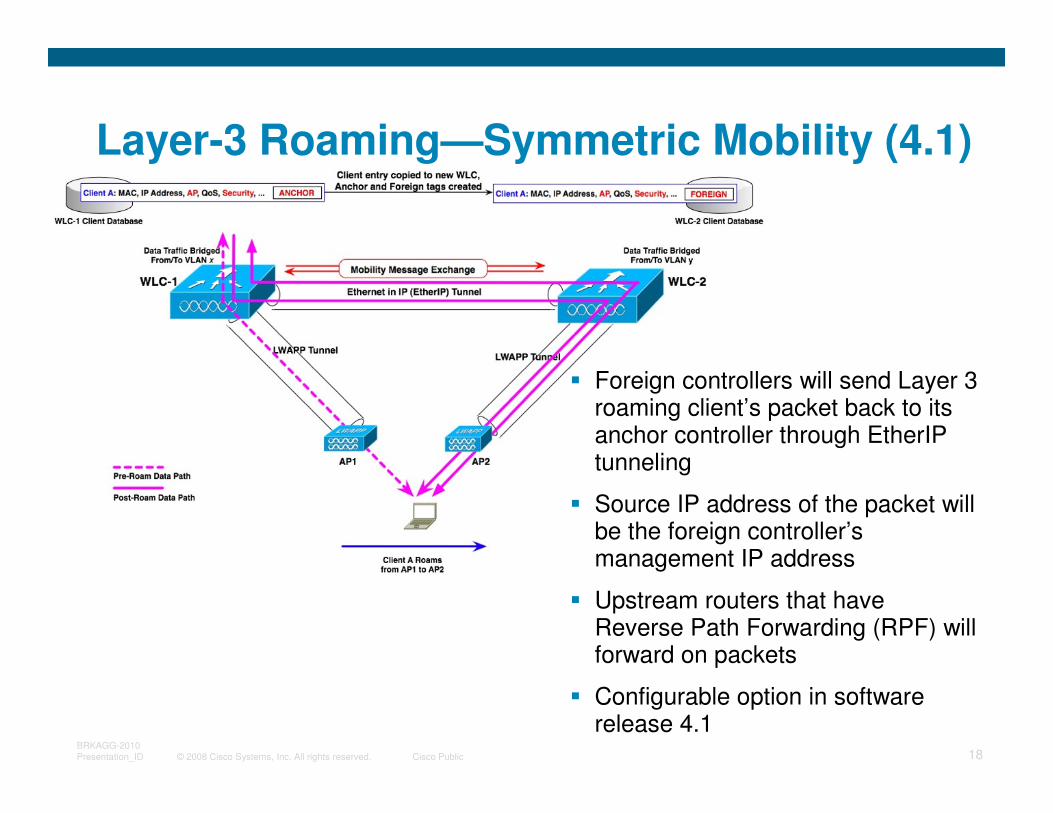
� Foreign controllers will send Layer 3 roaming client’s packet back to its anchor controller through EtherIP tunneling
� Source IP address of the packet will be the foreign controller’s management IP address
� Upstream routers that have Reverse Path Forwarding (RPF) will forward on packets
� Configurable option in software release 4.1
Layer-3 Roaming—Symmetric Mobility (4.1)
© 2008 Cisco Systems, Inc. All rights reserved. Cisco Public 19BRKAGG-2010
Presentation_ID
Roaming Requirements
� Roaming must be fast… Latency can be introduced by:
Client channel scanning and AP selection algorithms
Re-authentication of client device and re-keying
Refreshing of IP address
� Roaming must maintain security
Open auth, static WEP – Session continues on new AP
WPA/WPAv2 personal – New session key for encryption derived via standard handshakes
802.1x, 802.11i, WPA/WPAv2 enterprise – Client must be re-authenticated and new session key derived for encryption
© 2008 Cisco Systems, Inc. All rights reserved. Cisco Public 20BRKAGG-2010
Presentation_ID
Fast Secure Roaming
� Client channel scanning and AP selection algorithms—Improved via CCX features
� Refreshing of IP address—Irrelevant in controller-based architecture!
� Re-authentication of client device and re-keying
Cisco centralized key management (CCKM)
Proactive key caching (PKC)
© 2008 Cisco Systems, Inc. All rights reserved. Cisco Public 21BRKAGG-2010
Presentation_ID
Supporting Roaming—Design Best Practices and Caveats
� Minimize inter-controller roaming in your designs
� Design the network for � 10msec RTT latency between controllers
� Layer-3 roaming—consider the effects of things like RPF and stateful security features in your designs
� Use PKC and/or CCKM to speed up and secure roaming
� Client roaming behavior—mileage varies by vendor, driver, supplicant. Look for CCXv4 feature-set
© 2008 Cisco Systems, Inc. All rights reserved. Cisco Public 22BRKAGG-2010
Presentation_ID
QoS Overview
� Ensures packets receive the proper QoS handling end-to-end
� Makes sure packet will maintain QoS information as it traverses network
� Policing of 802.11e UP / 802.1p and IP DSCP values ensures end-points conform to network QoS policies
� Uses Cisco’s AVVID packet marking mappings and IEEE mappings as appropriate
� Support for Cisco 7920/7921 and Spectalink phones
© 2008 Cisco Systems, Inc. All rights reserved. Cisco Public 23BRKAGG-2010
Presentation_ID
WMM Overview
� WMM is a Wi-Fi Alliance interoperability certification, based on the IEEE 802.11e standard.
� WMM prioritizes traffic according to four Access Categories (AC) -voice, video, best effort, and background.
� WMM does not provide guaranteed throughput.
� When you enable QoS, the access point uses Wi-Fi Multimedia (WMM) mode by default.
� The access point adds each packet's class of service to the packet's 802.11 header to be passed to the receiving station.
© 2008 Cisco Systems, Inc. All rights reserved. Cisco Public 24BRKAGG-2010
Presentation_ID
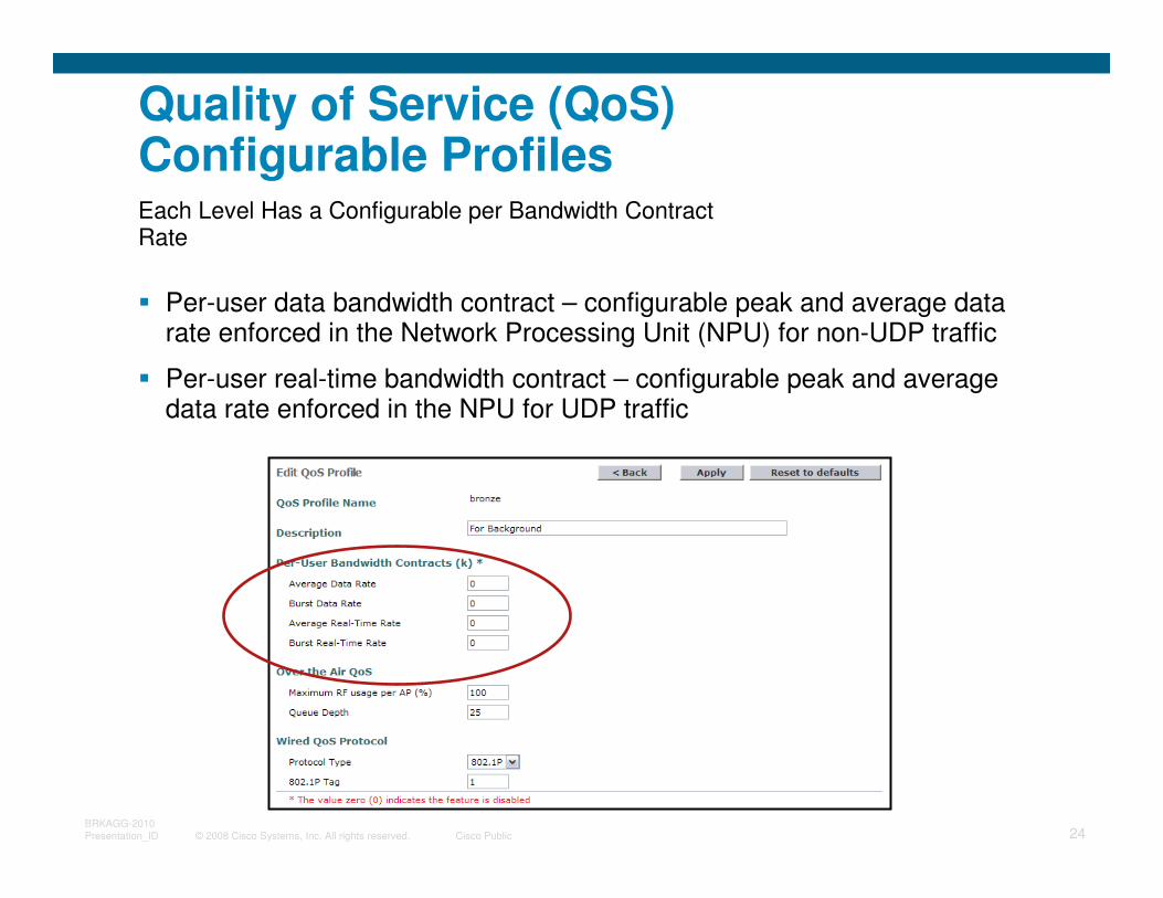
Quality of Service (QoS) Configurable Profiles
� Per-user data bandwidth contract – configurable peak and average data rate enforced in the Network Processing Unit (NPU) for non-UDP traffic
� Per-user real-time bandwidth contract – configurable peak and average data rate enforced in the NPU for UDP traffic
Each Level Has a Configurable per Bandwidth Contract Rate
© 2008 Cisco Systems, Inc. All rights reserved. Cisco Public 25BRKAGG-2010
Presentation_ID
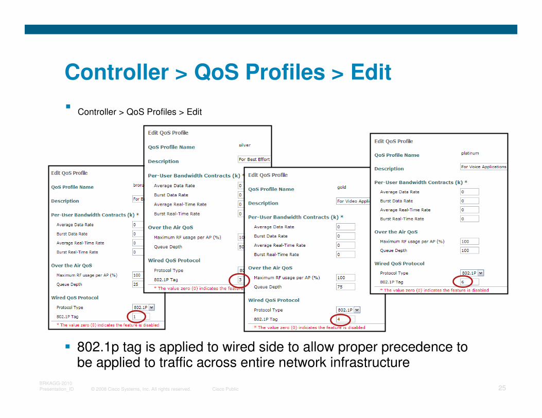
Controller > QoS Profiles > Edit
� 802.1p tag is applied to wired side to allow proper precedence to be applied to traffic across entire network infrastructure
� Controller > QoS Profiles > Edit
© 2008 Cisco Systems, Inc. All rights reserved. Cisco Public 26BRKAGG-2010
Presentation_ID
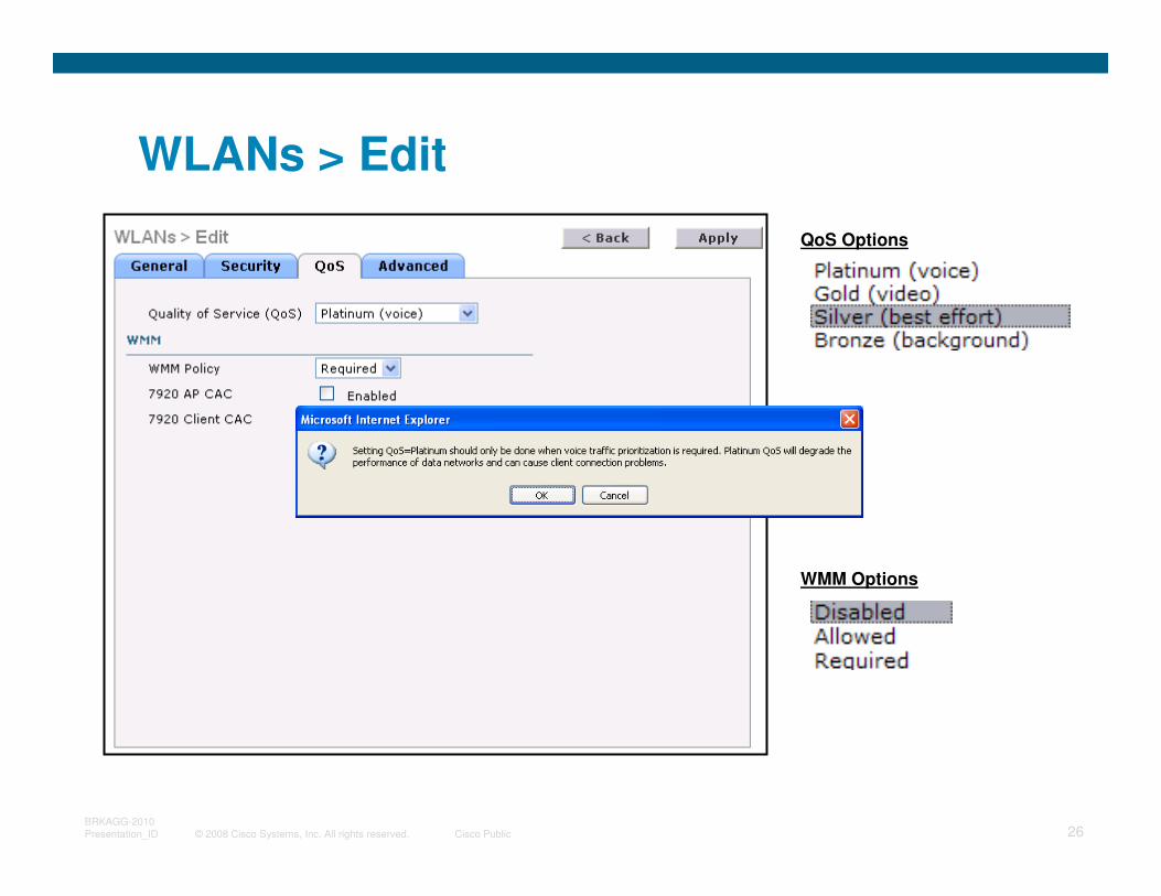
WLANs > Edit
WMM Options
QoS Options
© 2008 Cisco Systems, Inc. All rights reserved. Cisco Public 27BRKAGG-2010
Presentation_ID
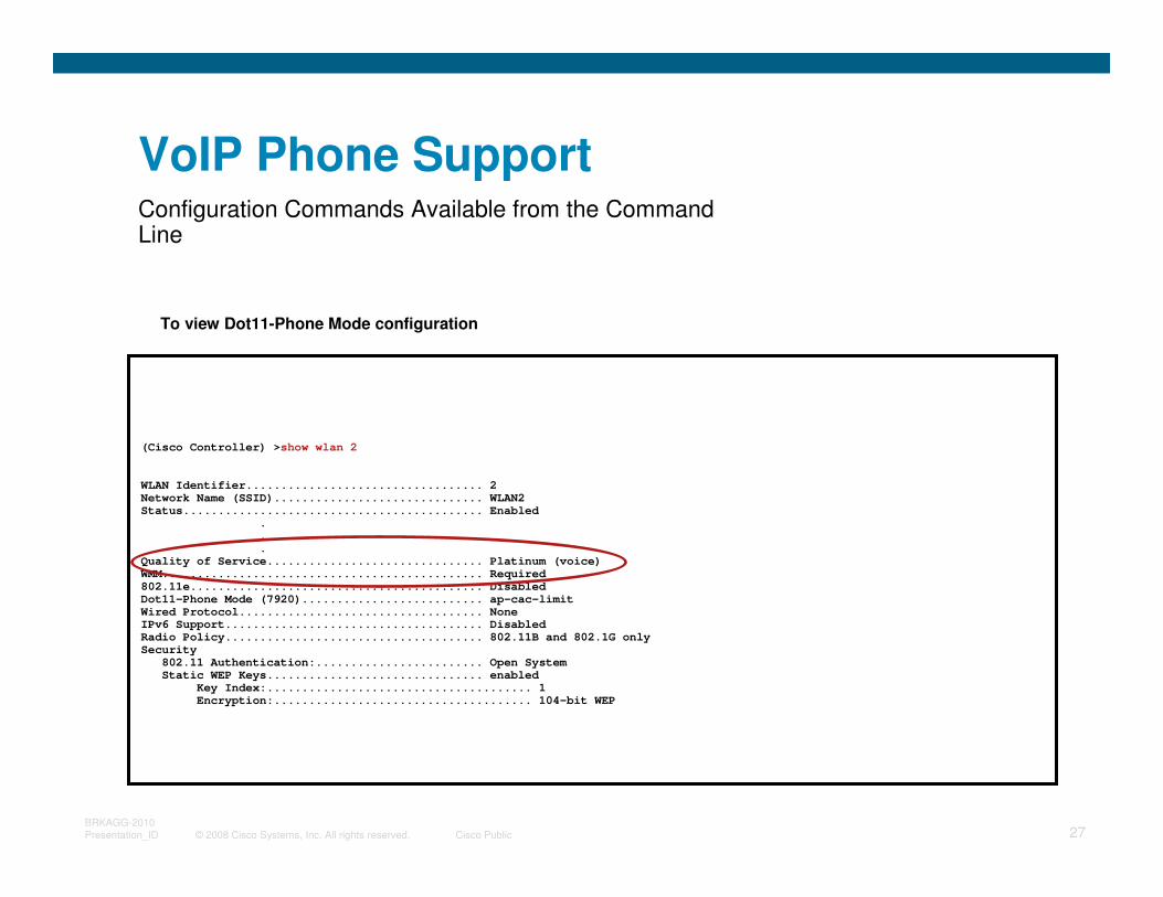
VoIP Phone SupportConfiguration Commands Available from the Command Line
To view Dot11-Phone Mode configuration
(Cisco Controller) >show wlan 2
WLAN Identifier.................................. 2
Network Name (SSID).............................. WLAN2
Status........................................... Enabled
.
.
.
Quality of Service............................... Platinum (voice)
WMM.............................................. Required
802.11e.......................................... Disabled
Dot11-Phone Mode (7920).......................... ap-cac-limit
Wired Protocol................................... None
IPv6 Support..................................... Disabled
Radio Policy..................................... 802.11B and 802.1G only
Security
802.11 Authentication:........................ Open System
Static WEP Keys............................... enabled
Key Index:...................................... 1
Encryption:..................................... 104-bit WEP
© 2008 Cisco Systems, Inc. All rights reserved. Cisco Public 28BRKAGG-2010
Presentation_ID
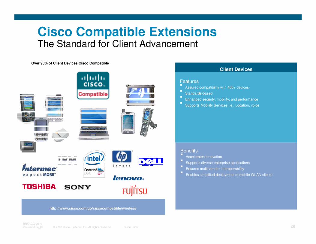
Cisco Compatible ExtensionsThe Standard for Client Advancement
http://www.cisco.com/go/ciscocompatible/wireless
Over 90% of Client Devices Cisco Compatible
Client Devices
Client Devices
Features� Assured compatibility with 400+ devices
� Standards-based
� Enhanced security, mobility, and performance
� Supports Mobility Services i.e.. Location, voice
Benefits� Accelerates innovation
� Supports diverse enterprise applications
� Ensures multi-vendor interoperability
� Enables simplified deployment of mobile WLAN clients
© 2008 Cisco Systems, Inc. All rights reserved. Cisco Public 29BRKAGG-2010
Presentation_ID
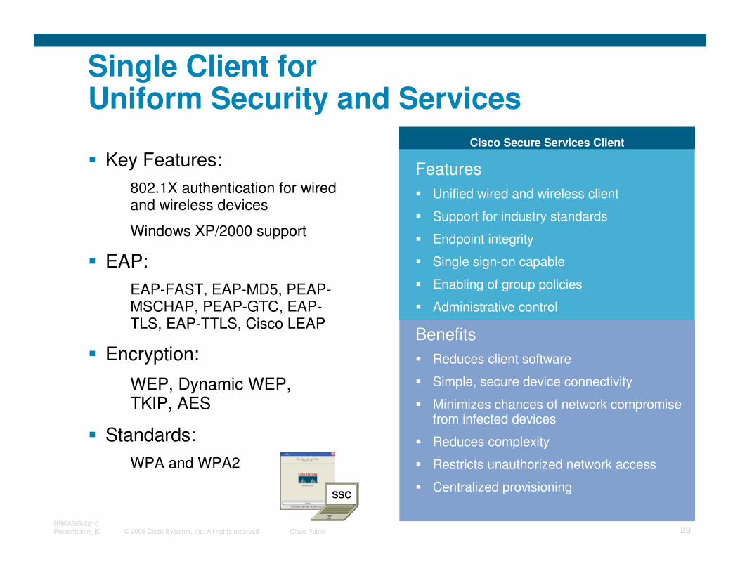
Cisco Secure Services Client
Single Client for Uniform Security and Services
Features
� Unified wired and wireless client
� Support for industry standards
� Endpoint integrity
� Single sign-on capable
� Enabling of group policies
� Administrative control
Benefits
� Reduces client software
� Simple, secure device connectivity
� Minimizes chances of network compromise from infected devices
� Reduces complexity
� Restricts unauthorized network access
� Centralized provisioningSSC
� Key Features:
802.1X authentication for wired and wireless devices
Windows XP/2000 support
� EAP:
EAP-FAST, EAP-MD5, PEAP-MSCHAP, PEAP-GTC, EAP-TLS, EAP-TTLS, Cisco LEAP
� Encryption:
WEP, Dynamic WEP, TKIP, AES
� Standards:
WPA and WPA2
© 2008 Cisco Systems, Inc. All rights reserved. Cisco Public 30BRKAGG-2010
Presentation_ID
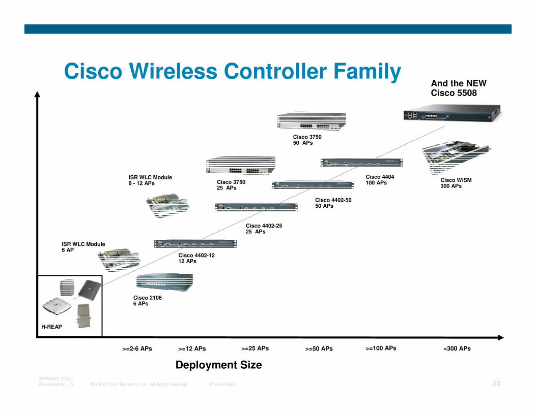
Cisco Wireless Controller Family
Cisco WiSM 300 APs
Deployment Size
>=100 APs>=25 APs>=2-6 APs
Cisco 21066 APs
ISR WLC Module6 AP
>=12 APs
H-REAP
>=50 APs
Cisco 375025 APs
Cisco 375050 APs
<300 APs
ISR WLC Module8 - 12 APs
Cisco 4404 100 APs
Cisco 4402-5050 APs
Cisco 4402-12 12 APs
Cisco 4402-2525 APs
And the NEW Cisco 5508
© 2008 Cisco Systems, Inc. All rights reserved. Cisco Public 31BRKAGG-2010
Presentation_ID
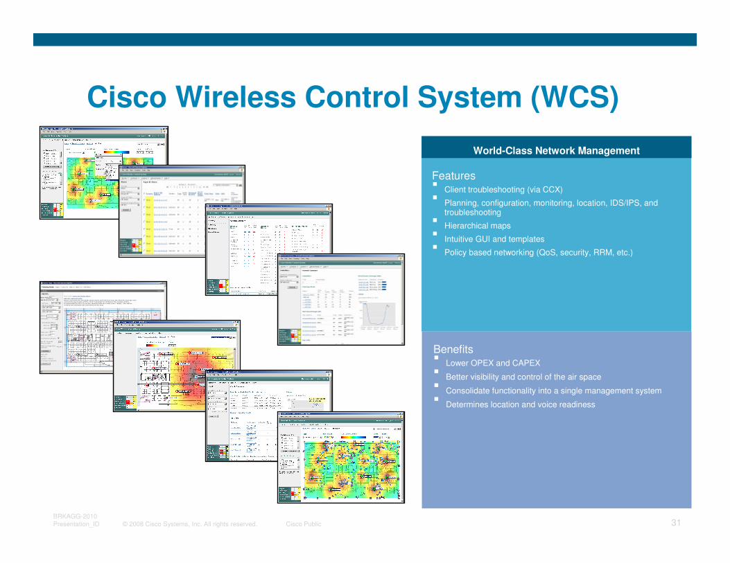
Cisco Wireless Control System (WCS)
World-Class Network Management
Features� Client troubleshooting (via CCX)� Planning, configuration, monitoring, location, IDS/IPS, and
troubleshooting � Hierarchical maps � Intuitive GUI and templates� Policy based networking (QoS, security, RRM, etc.)
Benefits� Lower OPEX and CAPEX
� Better visibility and control of the air space
� Consolidate functionality into a single management system
� Determines location and voice readiness
© 2008 Cisco Systems, Inc. All rights reserved. Cisco Public 32BRKAGG-2010
Presentation_ID