Embed Size (px)
Citation preview
Entity Relationship Diagram (ERD)
22 February 2011
An Introduction to designing a Database
• A database is a collection of data that is organized in such a manner that its contents can be readily accessed, managed and updated
• An Entity Relationship model (ERM) may be used to aid the development of a database– An ER model may be represented pictorially by ERDs
2
What is a Data Model?
• A detailed model that captures overall structure of organizational data while being independent of any implementation considerations
3
Rationale for using Data Modelling?
• Typically data modelling is carried out parallel with other requirements analysis and structuring steps during the systems analysis phase
• During this phase a data model is developed for the current system
• Following this, the data model supporting the scope and requirements of the proposed system is developed
4
ERD’s
• Entity Relationship Diagram is a form of data modelling
• Data modelling involves examining the data objects in a system and identifying the relationship between these objects
5
What is an Entity Relationship Diagram (ERD)?
• An ERD depicts data in terms of the entities and relationships described in an information system
• The primary purpose of an ERD is to document the logical structure of a database
6
7
Two Approaches to ERD’s
• The two most popular approaches to contructing entity relationship diagrams are:– SSADM– Chen ERD
• Visio provides stencils for constructing ERD’s using these apporaches
8
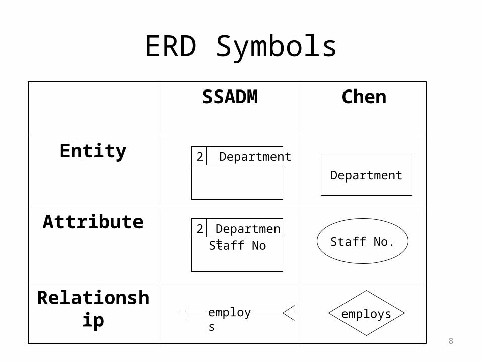
ERD Symbols
SSADM Chen
Entity
Attribute
Relationship
Department
Staff No.
employs
Staff NoDepartment
Department2
2
employs
9
An Entity
• An entity is a thing of interest to a system about which information is kept
• For example in a Hospital Administration System, some likely entities would include: Patient, Doctor, Operation, Ward
• Each of these things are of interest to the system and would have data stored about them
10
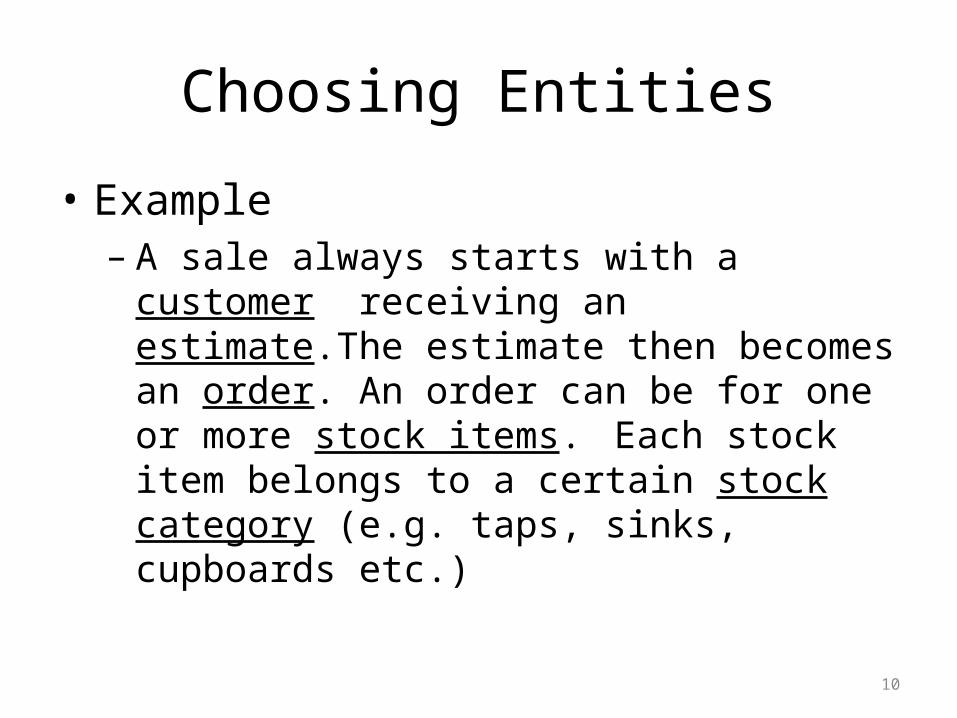
Choosing Entities
• Example– A sale always starts with a customer receiving an
estimate.The estimate then becomes an order. An order can be for one or more stock items. Each stock item belongs to a certain stock category (e.g. taps, sinks, cupboards etc.)
11
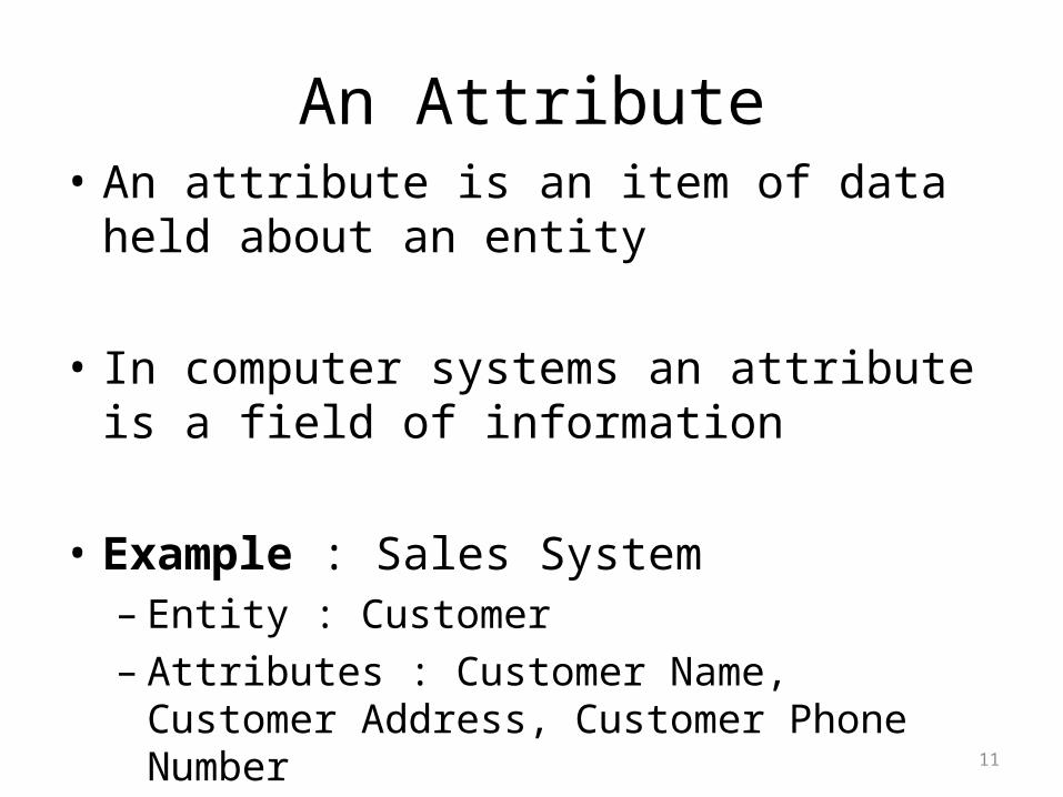
An Attribute• An attribute is an item of data held about an
entity
• In computer systems an attribute is a field of information
• Example : Sales System– Entity : Customer – Attributes : Customer Name, Customer Address,
Customer Phone Number
12
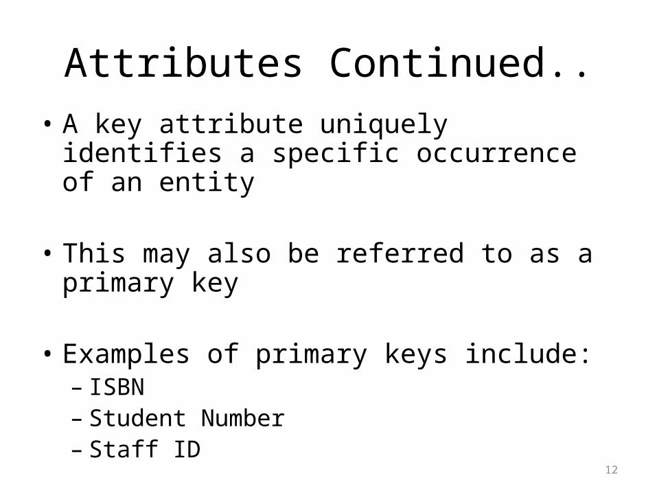
Attributes Continued..• A key attribute uniquely identifies a specific
occurrence of an entity
• This may also be referred to as a primary key
• Examples of primary keys include:– ISBN – Student Number – Staff ID
13
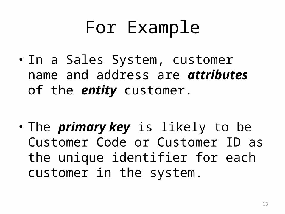
For Example
• In a Sales System, customer name and address are attributes of the entity customer.
• The primary key is likely to be Customer Code or Customer ID as the unique identifier for each customer in the system.
14
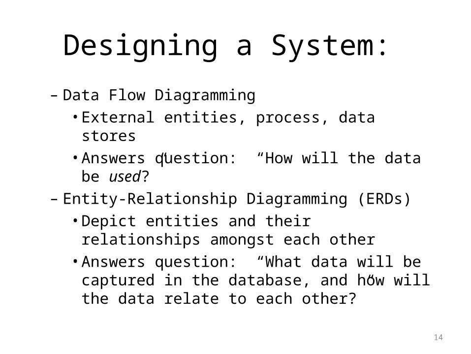
Designing a System:
– Data Flow Diagramming• External entities, process, data stores• Answers question: “How will the data be used?”
– Entity-Relationship Diagramming (ERDs)• Depict entities and their relationships amongst
each other• Answers question: “What data will be captured in
the database, and how will the data relate to each other?”
15
Example : Babysitter ServiceThe AITP Service Club wants to run a babysitting service. Customers call to request a sitter and the Club Coordinator assigns an employee to sit for the customer from a list of employees available for the particular day requested.
16
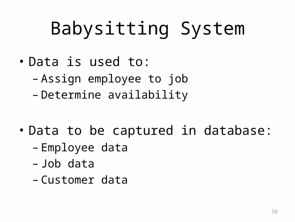
Babysitting System
• Data is used to: – Assign employee to job– Determine availability
• Data to be captured in database: – Employee data– Job data– Customer data
17
Entity-Relationship Model
• A logical representation of the data of an organization or business area in graphical form
18
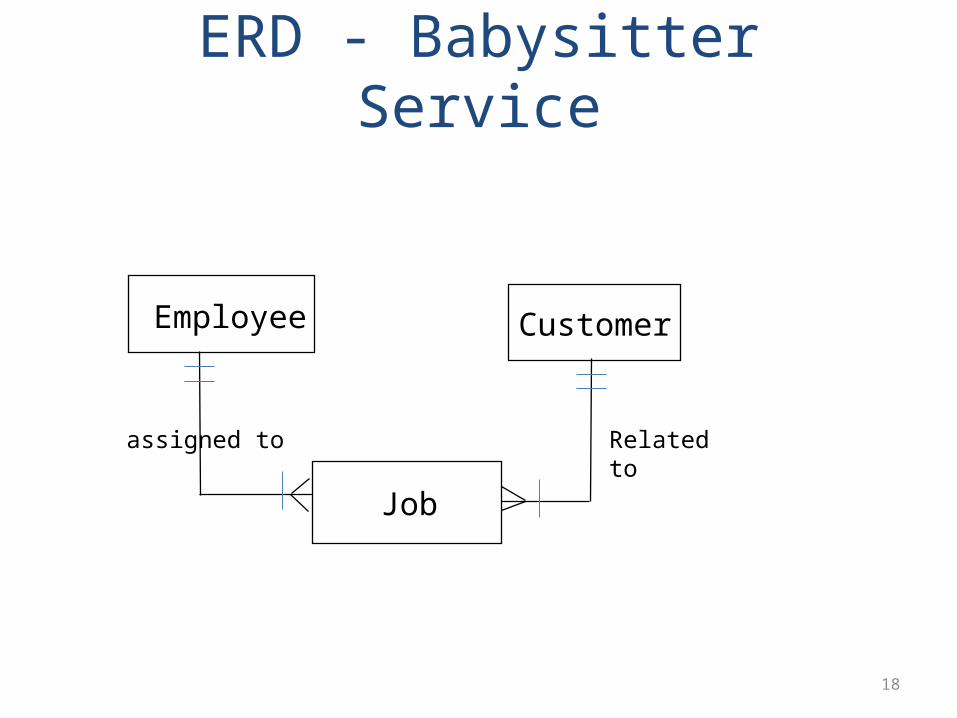
ERD - Babysitter Service
Employee
Job
Customer
assigned to Related to
19
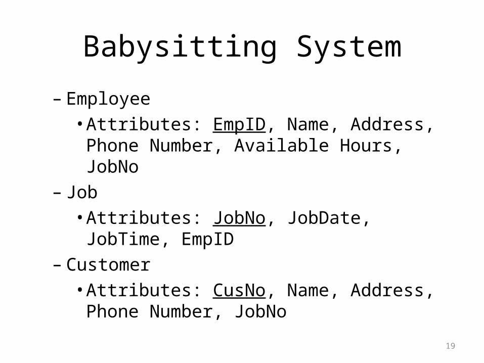
Babysitting System
– Employee• Attributes: EmpID, Name, Address, Phone
Number, Available Hours, JobNo – Job
• Attributes: JobNo, JobDate, JobTime, EmpID– Customer
• Attributes: CusNo, Name, Address, Phone Number, JobNo

21
Entity Instance• An entity instance is a single occurrence of an
entity type.• An entity type is described just once in a data
model while many instances of that data type may be represented by data stored in the system.– There is one EMPLOYEE entity type in most
organisations but there may be hundred or thousands of instances of this entity type in the company.

22
Choosing Entities
• Example– A sale always starts with a customer receiving an
estimate.The estimate then becomes an order. An order can be for one or more stock items. Each stock item belongs to a certain stock category (e.g. taps, sinks, cupboards etc.)
23
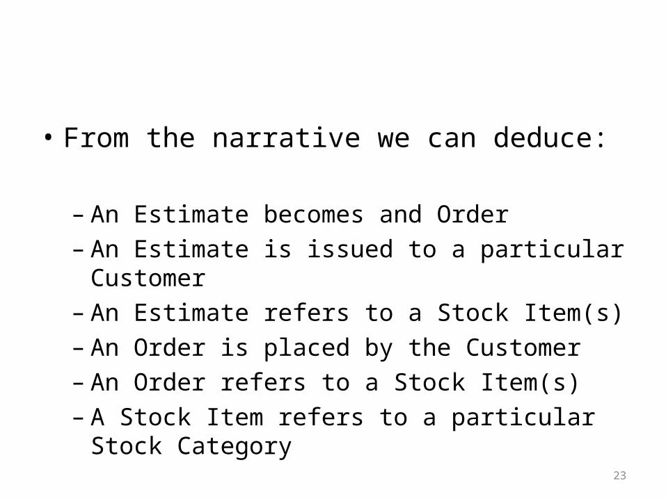
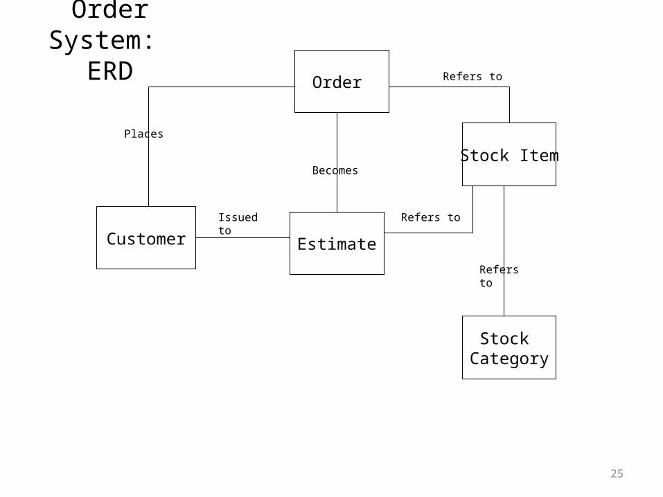
• From the narrative we can deduce:
– An Estimate becomes and Order– An Estimate is issued to a particular Customer– An Estimate refers to a Stock Item(s)– An Order is placed by the Customer– An Order refers to a Stock Item(s)– A Stock Item refers to a particular Stock Category

24
• From the narrative we can deduce:
– An Estimate becomes and Order– An Estimate is issued to a particular Customer– An Estimate refers to a Stock Item(s)– An Order is placed by the Customer– An Order refers to a Stock Item(s)– A Stock Item refers to a particular Stock Category
25
Order System: ERD
Customer
Order
Stock Item
Stock Category
Estimate
Places
Refers to
Becomes
Issued to
Refers to
Refers to
26
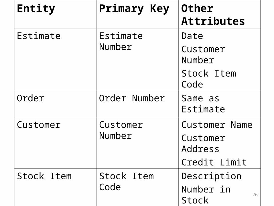
Entity Primary Key Other Attributes
Estimate Estimate Number Date
Customer Number
Stock Item Code
Order Order Number Same as Estimate
Customer Customer Number Customer Name
Customer Address
Credit Limit
Stock Item Stock Item Code Description
Number in Stock
Supplier Code
Stock Category Category Code Category Description
27
Entity Instance• An entity instance is a single occurrence of an
entity type.
• An entity type is described just once in a data model while many instances of that data type may be represented by data stored in the system.– There is one EMPLOYEE entity type in most
organisations but there may be hundred or thousands of instances of this entity type in the company.
• A relationship is an association between two entities that is important to the system.
• We must also consider the extent to which each entity is related to another.
28
ERD Relationships
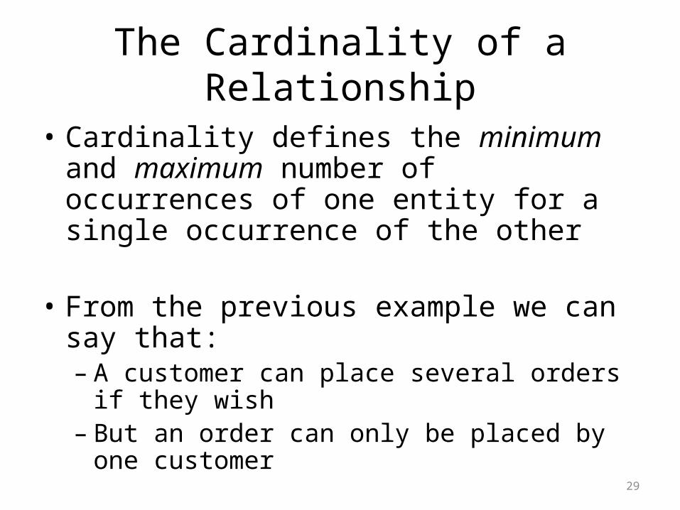
• Cardinality defines the minimum and maximum number of occurrences of one entity for a single occurrence of the other
• From the previous example we can say that:– A customer can place several orders if they wish– But an order can only be placed by one customer
29
The Cardinality of a Relationship
• Cardinality is bi-directional
• This means that it must be defined for both directions of the entity relationship.
30
Cardinality
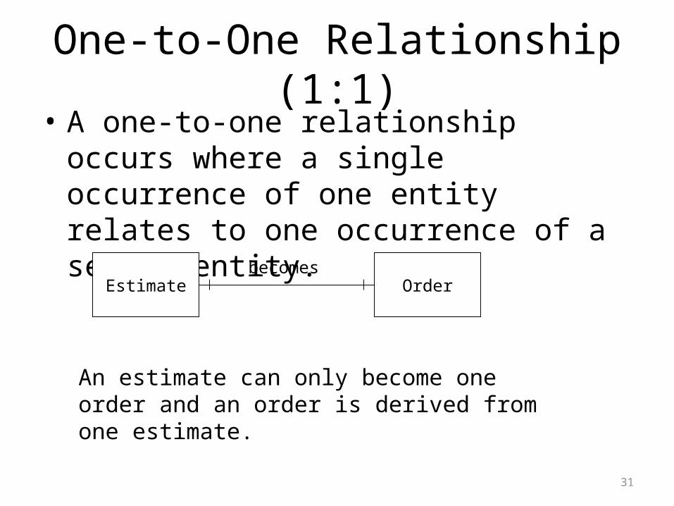
• A one-to-one relationship occurs where a single occurrence of one entity relates to one occurrence of a second entity.
31
One-to-One Relationship (1:1)
Estimate Order
An estimate can only become one order and an order is derived from one estimate.
becomes
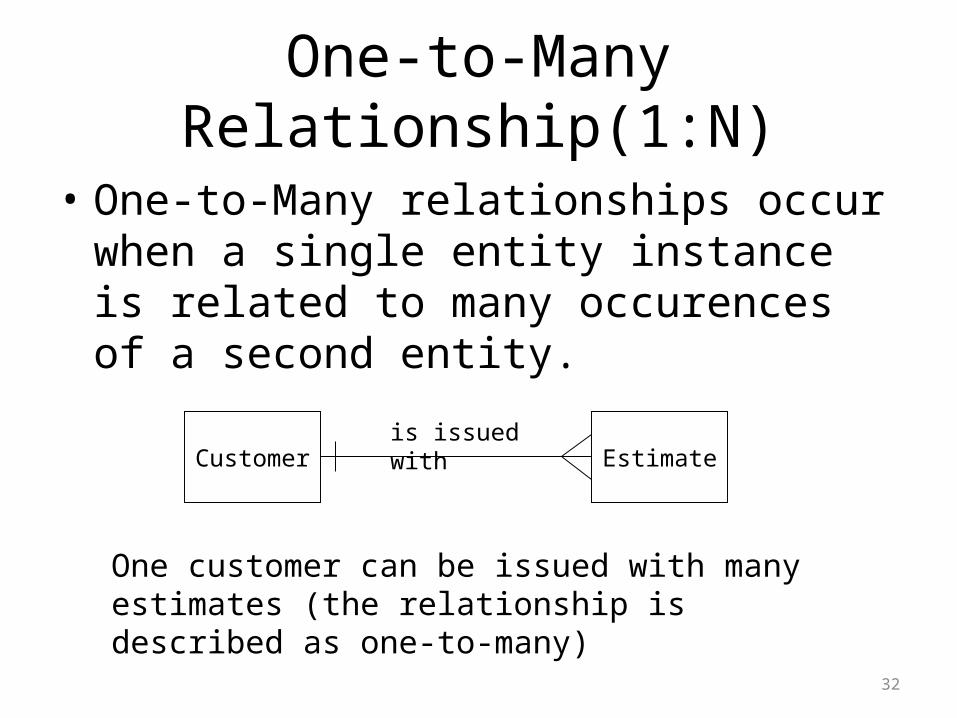
• One-to-Many relationships occur when a single entity instance is related to many occurences of a second entity.
32
One-to-Many Relationship(1:N)
Customer Estimate
One customer can be issued with many estimates (the relationship is described as one-to-many)
is issued with
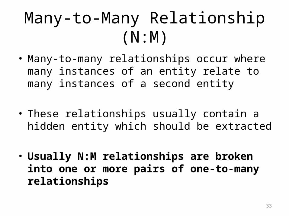
• Many-to-many relationships occur where many instances of an entity relate to many instances of a second entity
• These relationships usually contain a hidden entity which should be extracted
• Usually N:M relationships are broken into one or more pairs of one-to-many relationships
33
Many-to-Many Relationship (N:M)
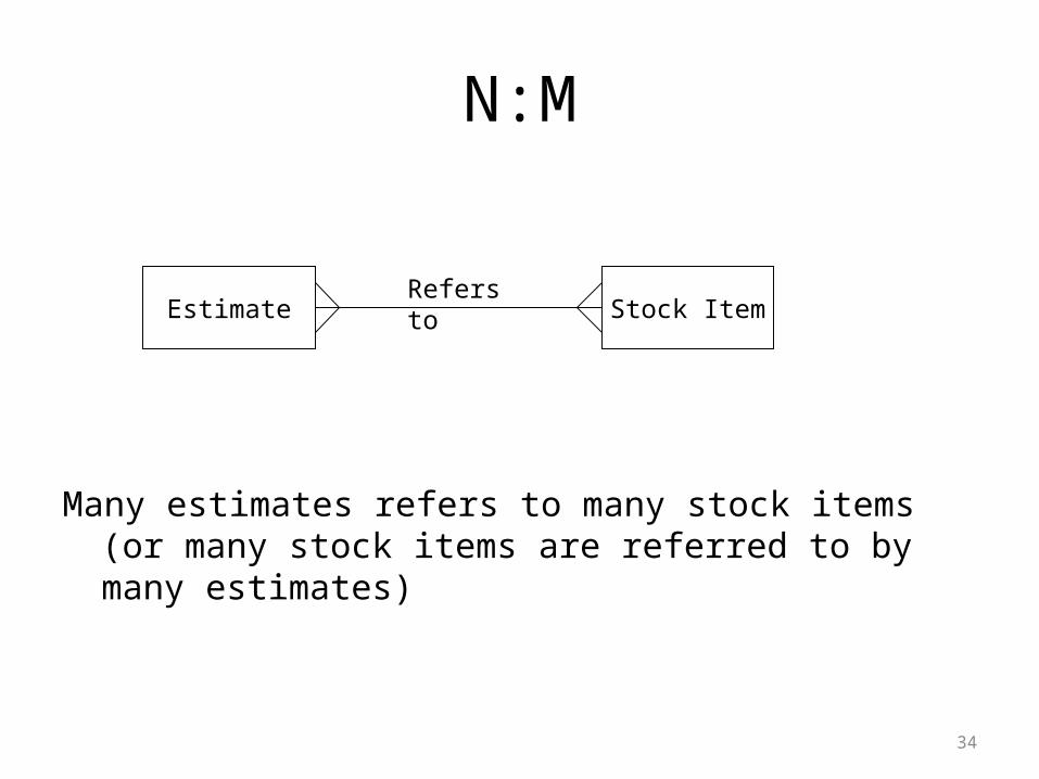
Many estimates refers to many stock items (or many stock items are referred to by many estimates)
34
N:M
Estimate Stock ItemRefers to
35
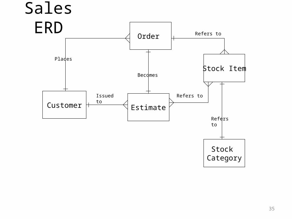
Sales ERD
Customer
Order
Stock Item
Stock Category
Estimate
Places
Refers to
Becomes
Issued to
Refers to
Refers to
• Optional Cardinality – Where the analyst considers whether an entity
occurrence at one end of the relationship can ever be present in the system without the presence of the corresonding occurrence of the entity at the other end of the relationship
• Mandatory Cardinality– When the occurrence of the entity at either end of the
relationship must be present in the system
36
Cardinality
• Some relationships are mandatory and some are optional
37
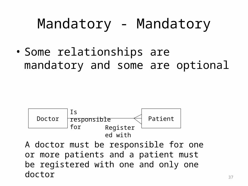
Mandatory - Mandatory
Doctor PatientIs responsible for
A doctor must be responsible for one or more patients and a patient must be registered with one and only one doctor
Registered with
38
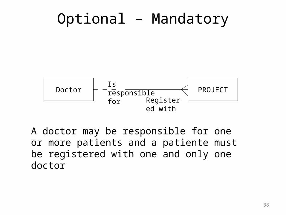
Optional – Mandatory
Doctor PROJECTIs responsible for
A doctor may be responsible for one or more patients and a patiente must be registered with one and only one doctor
Registered with
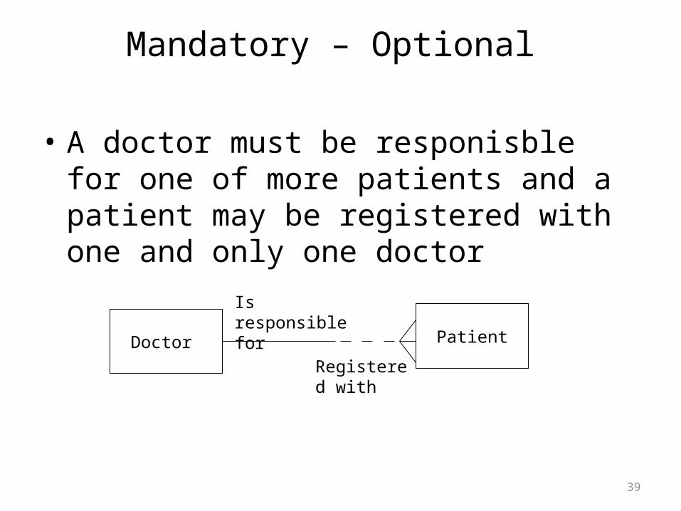
• A doctor must be responisble for one of more patients and a patient may be registered with one and only one doctor
39
Mandatory – Optional
Doctor Patient
Is responsible for
Registered with
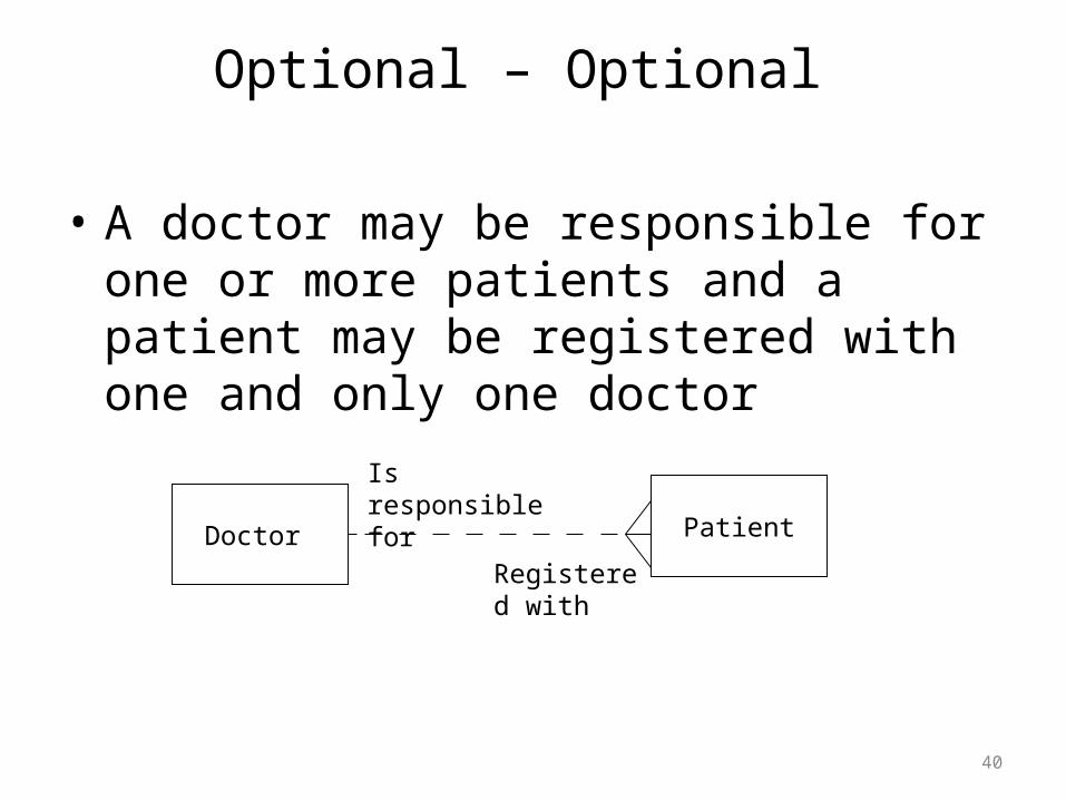
• A doctor may be responsible for one or more patients and a patient may be registered with one and only one doctor
40
Optional – Optional
Doctor Patient
Is responsible for
Registered with
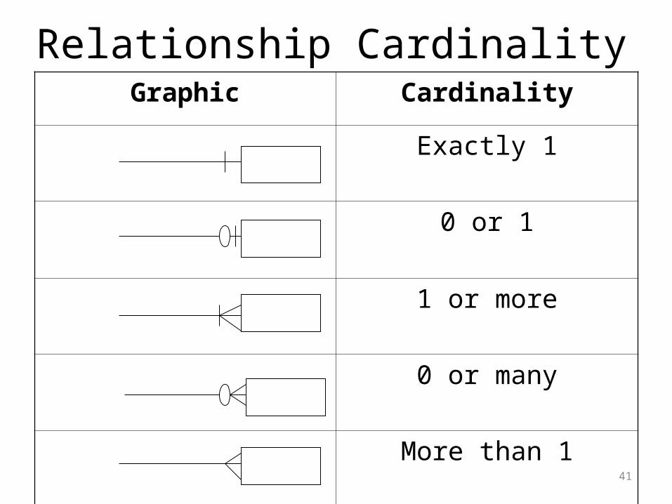
Relationship CardinalityGraphic Cardinality
Exactly 1
0 or 1
1 or more
0 or many
More than 141
Note • || denotes 1 and only
42