Embed Size (px)
Citation preview

assemblyexcavation installationbackfillingdesign examples
installation guide EnviroModuleTM2

Product specifications 2
Assembly 3
Excavation 5
Installation 6
Rainwater harvesting - residential 7
Rainwater harvesting - commercial 9
On-site detention 11
Infiltration 13
Backfilling and compaction 14
Contact information 15
contents
1

product specifications
1. EnviroModules must be installed with the 450mm side as the height to ensure maximum strength. 2. Standard duty modules are suitable for landscapedareas only. 3. Extra duty modules are required for trafficable areas such as driveways and carparks and where greater depth of cover is needed. A suitable pavement designed by a certified engineer is required over the surface of the tank. 4. Compressive strength tests were conducted by a certified testing authority and represent the maximum strength in a controlled environment that replicates the case when soil is uniformly distributed under a short term static load.
5. Safety factors should be employed to the compressive strength results. This is to allow for actual siteconditions, possible variations in recycled material and any potential creep factors.
400
450
Connector pinPipe connector
EnviroModule 2
technical data
Length: 600mm
Width: 400mm
Height: 450mm
Weight: 4 - 5 kg
Void area: 95%
Storage volume: 105 litres
Unrestricted flow rate: 3510 litres/min
Compressive strength
Standard duty module - 3 braces: 27.5 tonnes/m2
Extra duty module - 4 braces: 37.5 tonnes/m2
Minimum cover recommended
Standard duty module: 400mm
Extra duty module: 400mm
Maximum cover recommended
Standard duty module: 1200mm
Extra duty module: 1800mm
Overall maximum depth
Standard duty module: 2400mm
Extra duty module: 3000mm
Maximum height of modules
Standard duty module - 4 high: 1800mm
Extra duty module - 5 high: 2250mm
Service temperature: -30ºc + 120ºc
Module material: Recycled polypropylene
important design information
2
EnviroModuleTM2
600

AUSDRAIN EnviroModules are delivered flat-pack on pallets. Each pallet will either be marked EnviroModule side, EnviroModule brace or a combination of both. A fork lift is required on site to unload the pallets. The estimated assembly time is 1.5 mins for a standard duty module and 2 mins for an extra duty module. This includes the time required to unwrap the pallets, assemble each module and stack the modules ready for installation. There are two types of EnviroModule depending on the loading requirements on the job. The standard duty module (3 braces) is supplied for landscaped/non-trafficable areas. The extra duty module (4 braces) is supplied for trafficable areas and where greater
assembly of EnviroModules
useful tips
step 1 : assembly
Set up a sturdy workbench to assemble the modules on.
A rubber mallet is useful to lightly tap the modules together.
Assemble the modules as close to the installation area to avoid extra handling.
3
depth of cover is required. You will need to refer to thedesign specification or consult an Ausdrain representative to find out which module is required on your job prior to assembly.

STEP 3
Place the fourth side on
top. A few taps with a
rubber mallet will ensure
that the sides and braces
have been completely
locked into place and
the module assembly is
complete as shown in
Picture 3.
standard duty
STEP 1
Place one of the sides on
a solid flat surface and
ensure that the locating
pins are facing upward.
Locate a second side
upright onto pins as
shown in Picture 1.
STEP 2
Place a third side upright
onto pins and position the
internal braces by sliding
down the internal sleeve
of the two sides. There
are 3 braces required to
assemble a standard duty
module as shown in
Picture 2.
4 sides (600 x 400) & 3 braces
STEP 1
Place one of the sides on
a solid flat surface and
ensure that the locating
pins are facing upward.
Locate a second side
upright onto pins as
shown in Picture 1.
STEP 3
Place the fourth side on
top. A few taps with a
rubber mallet will ensure
that the sides and braces
have been completely
locked into place and
the module assembly is
complete as shown in
Picture 3.
STEP 2
Place a third side upright
onto pins and position
the internal braces by
sliding down the internal
sleeve of the two sides.
There are 4 braces
required to assemble
an extra duty module as
shown in Picture 2.
extra duty4 sides (600 x 400) & 4 braces
EnviroModuleTM2 - options
Picture 1
Picture 2
Picture 1
Picture 2
Picture 3 Picture 3
4

Excavate the pit allowing for the dimensions of the tank and at least 300-500mm to each side and 400mm of cover to the surface. It is important that there is sufficient width to the sides of the tank so that the backfill can be properly compacted.
It is recommended to excavate the pit in the form of atrapezoid. This will reduce any potential lateral pressures on the tank and prevent the sides of the excavation from subsiding. The pit should be benched and/or raked in line with safety regulations. A suitable safety fence should be erected around the perimeter of the excavated area.
The base should be prepared using a 100mm layer of coarse washed river sand. Ensure that the base is compacted to 95% and is level so that the modules will align correctly.
excavation and base preparation
step 2 : excavation
Where soft ground is encountered a layer of compacted road base may be required to establish a solid base for the tank to sit on. The sand layer will still be required in this situation. It is imperative that the tank isinstalled on a solid base to ensure structural integrity.
5

Four methods of installation
step 3 : installation
important information
Consult the design specification and refer to the installation method that is applicable to your particular project.
It is imperative that the modules are installed with the 450mm side in the upright position.
Ensure adequate drainage is installed around the tank perimeter to prevent any potential hydrostatic pressures.
Each tank should be fitted with an overflow or vent to prevent a vacuum inside the tank. Pre-filtration of stormwater is an essential part of each system. An AUSDRAIN EnviroSump or suitable GPT should be installed prior to water entering the tank.
EnviroModules must be handled with care at all times. Geotextile and liner should be secured down to prevent being blown by the wind.
Set up a string line from one corner along two sides of the tank so that the modules can be aligned correctly.
EnviroModule connector pins connect one on top of another and are useful to prevent any sideways movement.
b
a rainwater harvesting - residential
rainwater harvesting - commercial
d
c on-site detention
infiltration
6

Assemble the modules as per the instructions. Any molding defect in the product should be noted and set aside for replacement. Cut a vertical shaft according to the pipe size through a series of modules to accommodate the suction line. If the tank is 3 modules high, then cut out 3 modules in the same spot and sit them on top of one another. Place a layer of protection fabric on the compactedsand base and to the sides of the pit with enough overlap to cover the top of the tank. Place the liner base inside the pit above the fabric. The liner is supplied according to the dimensions ofthe tank. The inside of the liner should be kept clean at all times.
rainwater harvesting tank - residential
Place a layer of protection fabric across the base of the liner for the modules to sit on.
Begin installation of the tank structure by placing the assembled modules on top and beside one another ensuring the 450mm side is in the upright position. Connector pins (optional) can be used to join the modules on top of one another. Once the modules are in place pull the liner up the sides of the tank and secure the liner to the top layer of modules using plastic ties. Place the lid liner over the top of the tank and ensure the sides of the lid overlap the sides of the base securely. Using duct tape, secure the liner lid to the base.
1
2
3
4
5
6
7
8
a
7
step 3 : installation
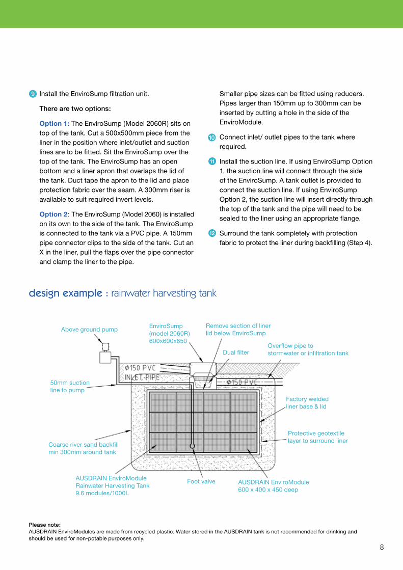
Install the EnviroSump filtration unit. There are two options: Option 1: The EnviroSump (Model 2060R) sits on top of the tank. Cut a 500x500mm piece from the liner in the position where inlet/outlet and suction lines are to be fitted. Sit the EnviroSump over the top of the tank. The EnviroSump has an open bottom and a liner apron that overlaps the lid of the tank. Duct tape the apron to the lid and place protection fabric over the seam. A 300mm riser is available to suit required invert levels. Option 2: The EnviroSump (Model 2060) is installed on its own to the side of the tank. The EnviroSump is connected to the tank via a PVC pipe. A 150mm pipe connector clips to the side of the tank. Cut an X in the liner, pull the flaps over the pipe connector and clamp the liner to the pipe.
Smaller pipe sizes can be fitted using reducers. Pipes larger than 150mm up to 300mm can be inserted by cutting a hole in the side of the EnviroModule.
Connect inlet/ outlet pipes to the tank where required.
Install the suction line. If using EnviroSump Option 1, the suction line will connect through the side of the EnviroSump. A tank outlet is provided to connect the suction line. If using EnviroSump Option 2, the suction line will insert directly through the top of the tank and the pipe will need to be sealed to the liner using an appropriate flange.
Surround the tank completely with protection fabric to protect the liner during backfilling (Step 4).
design example : rainwater harvesting tank
Protective geotextile layer to surround liner
Overflow pipe to stormwater or infiltration tank
50mm suction line to pump
Coarse river sand backfill min 300mm around tank
Remove section of liner lid below EnviroSump
Above ground pump
Factory welded liner base & lid
Foot valve
Dual filter
Please note:AUSDRAIN EnviroModules are made from recycled plastic. Water stored in the AUSDRAIN tank is not recommended for drinking and should be used for non-potable purposes only.
9
11
12
8
AUSDRAIN EnviroModule 600 x 400 x 450 deep
AUSDRAIN EnviroModule Rainwater Harvesting Tank 9.6 modules/1000L
EnviroSump(model 2060R) 600x600x650
10

Assemble the modules as per the instructions. Any molding defect in the product should be noted and set aside for replacement.
Place a layer of protection fabric on the compacted sand base and to the sides of the pit with enough overlap to cover the top of the tank.
Place the liner base inside the pit above the fabric. The inside of the liner should be kept clean at all times.
Place a layer of protection fabric across the base of the liner for the modules to sit on.
rainwater harvesting tank - commercial
If installing pre-cast pits within the tank these should now be positioned adjacent to inlet/outlet pipes. A triple layer of fabric is required under the pit to protect the liner. The pit may also act as a sump in the tank. If so, excavate an area under the pit to allow for the extra depth and pit dimensions. The base pit should be sized so that the top of the pit is in line with the top of the modules.
Begin installation of the tank structure by placing the assembled modules on top and beside one another ensuring the 450mm side is in the upright position. Connector pins (optional) can be used to join the modules on top of one another.
Once the modules are in place pull the liner up the sides of the tank and secure the overlap to the top of the tank. Each corner of the tank will require a neat fold if using a flat sheet liner.
1
2
3
5
6
7
9
step 3 : installation
4
b

Please note:AUSDRAIN EnviroModules are made from recycled plastic. Water stored in the AUSDRAIN tank is not recommended for drinking and should be used for non-potable purposes only.
Install the suction line to the pit or through the tank. If pre-cast pits are not used then a section of webbing in each module will need to be removed toallow the suction line to fit inside the tank. Adequately seal any penetrations of the suction line to the liner.
Surround the tank completely with protection fabric to protect the liner during backfilling (Step 4).
Pre-cast concrete pit to engineers detail
Pre-cast grated pit riser
Inlet to tank
1350mm 3 modules deep (indicative only)
AUSDRAIN EnviroModule 600 x 400 x 450 deep 9.6 modules/1000LRemovable maximesh
galvanised trash screen
Foot valve or submersablepump
Factory welded liner base and lid
50mm suction line to pump
Inlet pipe
Overflow pipeto stormwater
Coarse washed river sand min 300mm around tank
Protective geotextile layer to surround liner.
Place the lid liner over the top of the tank and ensure the sides of the lid overlap the sides of the base liner securely. Using duct tape, secure the liner lid to the base.
Cut the liner away from the inside perimeter of eachpit. Position the risers on top of the base effectivelywedging the liner in between. The risers should be installed to finished surface level. Connect inlet/outlet pipes to the tank where required.If connecting pipes through the liner an appropriate flange will be required. This can either be mechanicallyfixed to the pit or welded/glued to the liner. If the pipe connections are made through the pit above the tank surface then normal concreting/sealing of the pipe to the pit is required.
8
9
design example : rainwater harvesting tank
10
11
12
10

Assemble the modules as per the instructions. Any molding defect in the product should be noted and set aside for replacement.
Place a layer of protection fabric on the compacted sand base and to the sides of the pit with enough overlap to cover the top of the tank. Place the liner base inside the pit above the fabric. The inside of the liner should be kept clean at all times. Place a layer of protection fabric across the base of the liner for the modules to sit on.
on-site detention tank
The discharge control pit should now be positioned adjacent to inlet/outlet pipes. The pit will either sit to the side of the tank and connect via pipes to the tank or may sit within the tank liner depending on the design. If the pit is within the liner, a triple layer of fabric is required under the pit to protect the liner. The pit may also act as a sump in the tank. If so, excavate an area under the pit to allow for the extra depth and pit dimensions. The base pit should be sized so that the top of the pit is in line with the top of the modules. The discharge control pit will house the orifice plate and have trash screens over the orifice plate and inlet to the tank.
1
2
3
5
11
step 3 : installation
4
c

If the pit is within the liner, cut the liner away from the inside perimeter of each pit. Position the risers on top of the base effectively wedging the liner in between. The risers should be installed to finished surface level.
Connect inlet/outlet pipes to the tank where required.If connecting pipes through the liner an appropriate flange will be required. This can either be mechanically fixed to the pit or welded/glued to the liner. If the pipe connections are made through the pit above the tank surface then normal concreting/sealing of the pipe to the pit is required.
Surround the tank completely with protection
fabric to protect the liner during backfilling (Step 4).
AUSDRAIN EnviroModule 600 x 400 x 450 deep
design example : on-site detention tank (under carpark)
Removable maximesh galvanised trash screen
Geogrid layer to engineers design
AUSDRAIN EnviroSump Filtration Unit 600 x 600 x 700 or GPT
Granular Fill Min CBR15 300mm Cover
Asphalt/concrete flexible pavement to engineers design
Pre-cast grated pit to engineers detail
Orifice plate stormwater outlet
Impermeable liner to Ausdrain recommendation
Backfill with coarse washed river sand min 300mm
Inlet pipe to tank
Outlet pipe to pit
Begin installation of the tank structure by placing the assembled modules on top and beside one another ensuring the 450mm side is in the upright position. Connector pins (optional) can be used to join the modules on top of one another.
Once the modules are in place pull the liner up the sides of the tank and secure the overlap to the top of the tank. Each corner of the tank will require a neat fold if using a flat sheet liner. Place the lid liner over the top of the tank and ensure the sides of the lid overlap the sides of the base liner securely. Using duct tape, secure the liner lid to the base.
6
8
7
12
9
11
12
10

AUSDRAIN EnviroModule600 x 400 x 450 deep (9.25 modules/cubic m)
Overflow pipe
Surround tank ingeotextile fabric
Coarse washed river sand min 300mm around Infiltration Tank
300 x 300 grated surfaceoverflow pit (or connectedto stormwater)
100mm layer coarse washed river sandAUSDRAIN EnviroSump
Filtration Unit 600 x 600 x 700
Topsoil 300mm
Inlet Pipe
design example : infiltration tank
Assemble the modules as per the instructions. Any molding defect in the product should be noted and set aside for replacement. Place a layer of geotextile fabric on the compacted sand base and to the sides of the pit with enough overlap to cover the top of the tank. The fabric should be overlapped by 300mm at each seam.
Place an additional layer of fabric on the base for the modules to sit on.
If installing pre-cast pits within the tank these should now be positioned adjacent to inlet/outlet pipes. A triple layer of fabric is required under the pit to protect the base fabric if installing within the tank. Begin installation of the tank structure by placing the assembled modules on top and beside one another ensuring the 450mm side is in the upright position. Connector pins (optional) can be used to join the modules on top of one another.
Install EnviroSump/s or suitable GPT adjacent to the tank and allow for pipe connection to the tank.
Connect inlet/outlet pipes to the tank by using AUSDRAIN 150mm connectors or by cutting a holein the side of the module and inserting the pipe through (max. 300 dia). An X can be cut in the fabric, the fabric pulled over the pipe and clamped or ducttaped. For larger pipe diameters and concrete pipes a pre-cast pit should be installed within the tank structure to enable a secure connection. Surround the tank completely with the geotextile fabric and overlap (min 300mm) where necessary. It is recommended not to leave the fabric exposed for extended periods.
Backfill the tank as per the instructions (Step 4).
infiltration tank
1
2
3
5
6
8
7
9
13
step 3 : installation
4
d

Back-fill with coarse washed river sand to the sides of the tank. The backfill should be compacted in 300mm lifts to 95% standard proctor. Ensure the tank is compacted on all sides so the modules hold firmly together in situ. Cover the surface of the tank with a minimum 100mm layer of coarse washed river sand.
Place 300mm of clean fill over the 100mm sand layer. Compact to 95% using lightweight equipment on tracks. The remaining cover should be placed and compacted in 300mm lifts using machinery on tracks to a maximum of 8 tonnes. If installing the tank under a carpark or trafficable area it is recommended to use a layer of geogrid.
a) Place a 100mm layer of coarse river sand over the tank. The geogrid is then placed and should extend 500mm beyond the perimeter of the excavation.
backfilling and compaction
b) Place 300mm of clean fill over the sand layer andcompact to 100% using a small excavator on tracks.
c) Whilst a a reinforced concrete slab is preferable, a pavement consisting of stabilised road base andasphalt may also be placed over the tank. The pavement should be installed to engineers specifications.
Once installed section off the tank area to prevent heavy vehicles from driving across the tank during the construction period.
Ausdrain tanks are generally recommended for cars and light commercial vehicles. In some situations an Ausdrain tank can be designed for heavier vehicle traffic. This will require consultation with Ausdrain and approval by a certified engineer.
1
2
3 5
6
14
step 4 : backfilling
4

Disclaimer
2008 Australian Drainage Modules Pty Ltd. All reasonable care has
been taken in compiling the information in this brochure. The details
in this brochure are intended only as a guide in specifying and
installing AUSDRAIN™ products. It is the customers responsibility
to ensure that each product is suitable for its intended purpose and
that the actual conditions of use are suitable. AUSDRAIN™ assumes
no responsibillity for the specification and/or installation of its
products or for improper reliance upon or misuse of the data herein.
Due to continuous product development AUSRAIN™ reserves the
right to change product design and/or specifications without notice.
Australian Drainage Modules Pty Ltd
Trading as AUSDRAIN™
Manufactured from 100%environmentally friendly recycled plastics
For more in-depth information about AUSDRAINTM and the products the company provides contact:
T 61 2 9929 7650F 61 2 9929 7655 E [email protected] PO Box 164 Cammeray NSW 2062 Australia
1300 AUSDRAIN (1300 287 372) (Toll free within Australia) or visit www.ausdrain.com
Distributed by: