Embed Size (px)
Citation preview
MIL-STD-810F NOTICE 230 August 2002
DEPARTMENT OF DEFENSETEST METHOD STANDARD
ENVIRONMENTAL ENGINEERING CONSIDERATIONS AND LABORATORY TESTS
TO ALL HOLDERS OF MIL-STD-810F:1. THE FOLLOWING PAGES OF MIL-STD-810F HAVE BEEN REVISED AND SUPERSEDE THE PAGESLISTED:
NEW PAGE DATE SUPERSEDED PAGE DATECover Page 1 January 2000 Cover Page REPRINTED WITHOUT CHANGEPart One-ii 30 August 2002 Part One-ii 1 January 2000Part One-iii 30 August 2002 Part One-iii 1 January 2000Part One-iv 1 January 2000 Part One-iv REPRINTED WITHOUT CHANGEPart One-v 30 August 2002 Part One-v 1 January 2000Part One-vi 1 January 2000 Part One-vi REPRINTED WITHOUT CHANGEPart One-1 30 August 2002 Part One-1 1 January 2000Part One-2 30 August 2002 Part One-2 1 January 2000Part One-3 30 August 2002 Part One-3 1 January 2000Part One-4 30 August 2002 Part One-4 1 January 2000Part One-5 30 August 2002 Part One-5 1 January 2000Part One-6 30 August 2002 Part One-6 1 January 2000Part One-7 30 August 2002 Part One-7 1 January 2000Part One-8 30 August 2002 Part One-8 1 January 2000Part One-9 30 August 2002 Part One-9 1 January 2000Part One-10 30 August 2002 Part One-10 1 January 2000Part One-11 30 August 2002 Part One-11 1 January 2000Part One-12 30 August 2002 Part One-12 1 January 2000Part One-15 30 August 2002 Part One-15 1 January 2000Part One-16 1 January 2000 Part One-16 REPRINTED WITHOUT CHANGEPart One-17 1 January 2000 Part One-17 REPRINTED WITHOUT CHANGEPart One-18 30 August 2002 Part One-18 1 January 2000Part One-19 30 August 2002 Part One-19 1 January 2000Part One-20 1 January 2000 Part One-20 REPRINTED WITHOUT CHANGEPart One-23 30 August 2002 Part One-23 1 January 2000Part One-24 30 August 2002 Part One-24 1 January 2000
AMSC N/A AREA ENVR
DISTRIBUTION STATEMENT A. Approved for public release; distribution is unlimited.
NOTICE OFCHANGE
NOT MEASUREMENTSENSITIVE
2
NEW PAGE DATE SUPERSEDED PAGE DATEPart One A-3 30 August 2002 Part One A-3 1 January 2000Part One A-4 1 January 2000 Part One A-4 REPRINTED WITHOUT CHANGEPart One B-1 30 August 2002 Part One B-1 1 January 2000Part One B-2 30 August 2002 Part One B-2 1 January 2000Part One C-3 30 August 2002 Part One C-3 1 January 2000Part One C-4 30 August 2002 Part One C-4 1 January 2000
Index-1 30 August 2002 Index-1 1 January 2000Index-2 30 August 2002 Index-2 1 January 2000Index-3 1 January 2000 Index-3 REPRINTED WITHOUT CHANGEIndex-4 30 August 2002 Index-4 1 January 2000Index-5 30 August 2002 Index-5 1 January 2000
Part Two-1 30 August 2002 Part Two-1 1 January 2000500.4-3 30 August 2002 500.4-3 1 January 2000500.4-4 30 August 2002 500.4-4 1 January 2000501.4-1 30 August 2002 501.4-1 1 January 2000501.4-2 1 January 2000 501.4-2 REPRINTED WITHOUT CHANGE501.4-3 1 January 2000 501.4-3 REPRINTED WITHOUT CHANGE501.4-4 30 August 2002 501.4-4 1 January 2000501.4-5 1 January 2000 501.4-5 REPRINTED WITHOUT CHANGE501.4-6 30 August 2002 501.4-6 1 January 2000501.4-9 30 August 2002 501.4-9 1 January 2000501.4-10 30 August 2002 501.4-10 1 January 2000501.4-11 30 August 2002 501.4-11 1 January 2000501.4-12 1 January 2000 501.4-12 REPRINTED WITHOUT CHANGE502.4-7 30 August 2002 502.4-7 1 January 2000502.4-8 1 January 2000 502.4-8 REPRINTED WITHOUT CHANGE503.4-1 30 August 2002 503.4-1 1 January 2000503.4-2 1 January 2000 503.4-2 REPRINTED WITHOUT CHANGE503.4-3 1 January 2000 503.4-3 REPRINTED WITHOUT CHANGE503.4-4 30 August 2002 503.4-4 1 January 2000503.4-5 1 January 2000 503.4-5 REPRINTED WITHOUT CHANGE503.4-6 30 August 2002 503.4-6 1 January 2000503.4-7 1 January 2000 503.4-7 REPRINTED WITHOUT CHANGE503.4-8 30 August 2002 503.4-8 1 January 2000504-1 1 January 2000 504-1 REPRINTED WITHOUT CHANGE504-2 30 August 2002 504-2 1 January 2000504-5 30 August 2002 504-5 1 January 2000504-6 1 January 2000 504-6 REPRINTED WITHOUT CHANGE505.4-1 30 August 2002 505.4-1 1 January 2000505.4-2 1 January 2000 505.4-2 REPRINTED WITHOUT CHANGE505.4-3 30 August 2002 505.4-3 1 January 2000505.4-4 30 August 2002 505.4-4 1 January 2000505.4-5 30 August 2002 505.4-5 1 January 2000
3
NEW PAGE DATE SUPERSEDED PAGE DATE505.4-6 30 August 2002 505.4-6 1 January 2000505.4-7 30 August 2002 505.4-7 1 January 2000505.4-8 30 August 2002 505.4-8 1 January 2000505.4-9 30 August 2002 505.4-9 1 January 2000505.4-10 1 January 2000 505.4-10 REPRINTED WITHOUT CHANGE505.4-11 30 August 2002 505.4-11 1 January 2000505.4-12 1 January 2000 505.4-12 REPRINTED WITHOUT CHANGE505.4A-1 1 January 2000 505.4A-1 REPRINTED WITHOUT CHANGE505.4A-2 30 August 2002 505.4A-2 1 January 2000506.4-1 30 August 2002 506.4-1 1 January 2000506.4-2 1 January 2000 506.4-2 REPRINTED WITHOUT CHANGE506.4-3 30 August 2002 506.4-3 1 January 2000506.4-4 30 August 2002 506.4-4 1 January 2000506.4-5 30 August 2002 506.4-5 1 January 2000506.4-6 30 August 2002 506.4-6 1 January 2000506.4-7 30 August 2002 506.4-7 1 January 2000506.4-8 30 August 2002 506.4-8 1 January 2000506.4-9 30 August 2002 506.4-9 1 January 2000506.4-10 1 January 2000 506.4-10 REPRINTED WITHOUT CHANGE507.4-1 30 August 2002 507.4-1 1 January 2000507.4-2 30 August 2002 507.4-2 1 January 2000507.4-5 1 January 2000 507.4-5 REPRINTED WITHOUT CHANGE507.4-6 30 August 2002 507.4-6 1 January 2000507.4-7 30 August 2002 507.4-7 1 January 2000507.4-8 1 January 2000 507.4-8 REPRINTED WITHOUT CHANGE508.5-1 30 August 2002 508.5-1 1 January 2000508.5-2 1 January 2000 508.5-2 REPRINTED WITHOUT CHANGE508.5-9 30 August 2002 508.5-9 1 January 2000508.5-10 30 August 2002 508.5-10 1 January 2000508.5A-1 30 August 2002 NEW PAGE508.5A-2 30 August 2002 NEW PAGE509.4-3 30 August 2002 509.4-3 1 January 2000509.4-4 1 January 2000 509.4-4 REPRINTED WITHOUT CHANGE509.4-5 30 August 2002 509.4-5 1 January 2000509.4-6 30 August 2002 509.4-6 1 January 2000509.4-7 30 August 2002 509.4-7 1 January 2000509.4-8 1 January 2000 509.4-8 REPRINTED WITHOUT CHANGE510.4-9 1 January 2000 510.4-9 REPRINTED WITHOUT CHANGE510.4-10 30 August 2002 510.4-10 1 January 2000511.4-1 30 August 2002 511.4-1 1 November 2000511.4-2 30 August 2002 511.4-2 1 January 2000511.4-3 30 August 2002 511.4-3 1 January 2000511.4-4 30 August 2002 511.4-4 1 January 2000
4
NEW PAGE DATE SUPERSEDED PAGE DATE511.4-5 30 August 2002 511.4-5 1 January 2000511.4-6 30 August 2002 511.4-6 1 January 2000511.4-7 30 August 2002 511.4-7 1 November 2000511.4-8 30 August 2002 511.4-8 1 November 2000REMOVE 511.4-9 1 November 2000REMOVE 511.4-10 1 November 2000513.5-11 30 August 2002 513.5-11 1 January 2000513.5-12 1 January 2000 513.5-12 REPRINTED WITHOUT CHANGE514.5-11 30 August 2002 514.5-11 1 January 2000514.5-12 1 January 2000 514.5-12 REPRINTED WITHOUT CHANGE514.5-19 1 January 2000 514.5-19 REPRINTED WITHOUT CHANGE514.5-20 30 August 2002 514.5-20 1 January 2000514.5-21 1 January 2000 514.5-21 REPRINTED WITHOUT CHANGE514.5-22 30 August 2002 514.5-22 1 January 2000514.5A-5 1 January 2000 514.5A-5 REPRINTED WITHOUT CHANGE514.5A-6 30 August 2002 514.5A-6 1 January 2000514.5A-9 1 January 2000 514.5A-9 REPRINTED WITHOUT CHANGE514.5A-10 30 August 2002 514.5A-10 1 January 2000514.5A-13 30 August 2002 514.5A-13 1 January 2000514.5A-14 30 August 2002 514.5A-14 1 January 2000514.5A-15 1 January 2000 514.5A-15 REPRINTED WITHOUT CHANGE514.5A-16 30 August 2002 514.5A-16 1 January 2000514.5C-3 1 January 2000 514.5C-3 REPRINTED WITHOUT CHANGE514.5C-4 30 August 2002 514.5C-4 1 January 2000514.5C-5 30 August 2002 514.5C-5 1 January 2000514.5C-6 1 January 2000 514.5C-6 REPRINTED WITHOUT CHANGE514.5C-7 30 August 2002 514.5C-7 1 January 2000514.5C-8 30 August 2002 514.5C-8 1 January 2000514.5C-9 30 August 2002 514.5C-9 1 January 2000514.5C-10 1 January 2000 514.5C-10 REPRINTED WITHOUT CHANGE514.5C-13 30 August 2002 514.5C-13 1 January 2000514.5C-14 1 January 2000 514.5C-14 REPRINTED WITHOUT CHANGE514.5C-15 1 January 2000 514.5C-15 REPRINTED WITHOUT CHANGE514.5C-16 30 August 2002 514.5C-16 1 January 2000516.5-31 30 August 2002 516.5-31 1 January 2000516.5-32 30 August 2002 516.5-32 1 January 2000516.5-33 1 January 2000 516.5-33 REPRINTED WITHOUT CHANGE516.5-34 30 August 2002 516.5-34 1 January 2000520.2-1 30 August 2002 520.2-1 1 January 2000520.2-2 1 January 2000 520.2-2 REPRINTED WITHOUT CHANGE520.2-11 30 August 2002 520.2-11 1 January 2000520.2-12 1 January 2000 520.2-12 REPRINTED WITHOUT CHANGE
5
NEW PAGE DATE SUPERSEDED PAGE DATE520.2A-3 30 August 2002 520.2A-3 1 January 2000520.2A-4 1 January 2000 520.2A-4 REPRINTED WITHOUT CHANGE520.2A-5 1 January 2000 520.2A-5 REPRINTED WITHOUT CHANGE520.2A-6 30 August 2002 520.2A-6 1 January 2000522-3 30 August 2002 522-3 1 January 2000522-4 30 August 2002 522-4 1 January 2000 .
2. RETAIN THIS NOTICE AND INSERT BEFORE TABLE OF CONTENTS.
3. Holders of MIL-STD-810F will verify that page changes indicated above have been entered. This notice pagewill be retained as a check sheet. This issuance, together with appended pages, is a separate publication. Eachnotice is to be retained by stocking points until the standard is completely revised or canceled.
Custodians: Preparing activity:Army – TE Air Force – 11Navy – AS (Project ENVR-0050)Air Force – 11
Review activities:Army – AR, AT, AV, CE, CR, GL, HD, MI, MT, SMNavy – CH, EC, MC, OS, SH, YDAir Force – 13, 19

NOT MEASUREMENTSENSITIVE
MIL-STD-810F1 January 2000
SUPERSEDINGMIL-STD-810E14 July 1989
DEPARTMENT OF DEFENSETEST METHOD STANDARD
FOR
ENVIRONMENTAL ENGINEERING CONSIDERATIONS
AND LABORATORY TESTS
AMSC N/A AREA ENVR
DISTRIBUTION STATEMENT A: Approved for public release; distribution is unlimited.
REPRINTED WITHOUT CHANGE.
MIL-STD-810F30 August 2002
Part One-ii
FOREWORD
This test method standard is approved for use by all Departments and Agencies of the Department of Defense(DoD). Although prepared specifically for DoD applications, this standard may be tailored for commercialapplications as well. MIL-STD-810F is a significant revision of MIL-STD-810E. Much of the standard is rewrittencompletely to provide clearer direction. The primary emphases are still the same -- tailoring a materiel item'senvironmental design and test limits to the conditions that the specific materiel will experience throughout itsservice life, and establishing laboratory test methods that replicate the effects of environments on materiel ratherthan trying to reproduce the environments themselves. However, the "F" revision has been expanded significantlyup front to explain how to implement the environmental tailoring process throughout the materiel acquisition cycle.
This revision recognizes that the environmental design and test tailoring process has expanded to involve a widerange of managerial and technical interests. Accordingly, this revision orients environmental design and testdirection toward three basic types of users who have distinctly different, although closely associated, interests: program managers who, among other responsibilities, ensure proposed concepts and systems are valid and functional inintended operational environments; environmental engineering specialists (EES), who enter the acquisition processearly to assist combat and materiel developer tailoring efforts by preparing life cycle environmental profiles anddrafting tailored design criteria and test programs, and the design, test, and evaluation community, whose analysts,engineers, and facility operators use tailored designs and tests to meet user needs.
The most visible difference in the "F" revision is that the overall document is in two parts.
Part One describes management, engineering, and technical roles in the environmental design and test tailoringprocess. It focuses on the process of tailoring materiel design and test criteria to the specific environmentalconditions a materiel item is likely to encounter during its service life. New appendices support the succinctlypresented text of Part One. Appendix A contains complete descriptions of environmental engineering tasks. Thesetasks, along with management information in Appendix B and EES guidance in Appendix C, will help to ensure theenvironmental design and test tailoring process is implemented and documented according to the disciplined, butflexible approach to materiel acquisition called for in Department of Defense (DoD) 5000-series documents(DoDD 5000.1). Terms used in this standard relating to the materiel acquisition process are limited to terms used inthe DoD 5000-series documents; to avoid confusion and promote simplicity, service-specific terms/processes arenot used.
Part Two contains environmental laboratory test methods to be applied according to the general and specific testtailoring guidelines described in Part One. It is important to emphasize that these methods are not to be called out inblanket fashion nor applied as unalterable routines, but are to be selected and tailored to generate the most relevanttest data possible.
To support the tailoring process described in Part One, each test method in Part Two contains some environmentaldata and references, and identifies tailoring opportunities for the particular method. Some methods afford a widelatitude for tailoring; some can be tailored up to established limits, and some have relatively few tailoring options. Whenever possible, each method contains background rationale to help determine the appropriate level of tailoring. Each test method supports the test engineer and test facility operator by describing preferred laboratory testfacilities and methodologies. Any specific tailoring information and values contained in these test methods shouldbe supplanted by more up-to-date or program-specific information when available.
When applied properly, the environmental management and engineering processes described in this standard can beof enormous value in generating confidence in the environmental worthiness and overall durability of materielsystem design. However, it is important to recognize that there are limitations inherent in laboratory testing thatmake it imperative to use proper caution and engineering judgment when extrapolating these laboratory results toresults that may be obtained under actual service conditions. In many cases, real-world environmental stresses(singularly or in combination) cannot be duplicated practically or reliably in test laboratories. Therefore, users
SUPERSEDES PAGE PART ONE-II OF MIL-STD-810F.
MIL-STD-810F30 August 2002
Part One-iii
should not assume that a system or component that passes laboratory tests of this standard also would passfield/fleet verification trials. DoD 5000-series documents call for component technology to be demonstrated inrelevant environments to reduce risk on components and subsystems which have been demonstrated only inlaboratory environments (DoDI 5000.2).
The US Department of Defense would like to thank the following individuals for their contributions toward thedevelopment and publication of MIL-STD-810F:
Anderson, Andy – United Defense Merritt, Ron – US Navy, Naval Air Warfare Center
Bair, Jim – US Air Force, Wright-Patterson AFB Moriceau, Jacques – LRBA, France
Bell, Dwayne – US Air Force, Eglin AFB Moss, Ron – Ordnance Board, United Kingdom
Caruso, Hank – G’s and Degrees Sullivan, Jamie – US Army, Redstone Technical TestCenter
Connon, Skip – US Army, Aberdeen Test Center Tanner, Steve – US Navy, Naval Air Warfare Center
Egbert, Herb – US Army Developmental Test Command
Walton, Scott – US Army, Aberdeen Test Center
Galloway, Judy – US Army, Aberdeen Test Center Weaver, Earl – US Air Force, Wright-Patterson AFB
Henry, Connie – US Air Force, Wright-Patterson AFB Williamson, Roger – US Army Test and EvaluationCommand
MacMartin, Dave – National Defence Headquarters,Canada
Also, a special thank you to Herb Egbert, Chairman of the MIL-STD-810 revision committee for his leadership,dedication, and perseverance in revising this document.
This standard is intended to be a "living document" that will be updated as new concepts, technologies, andmethodologies evolve. Address beneficial comments (recommended changes, additions, deletions) along with clear,supporting rationale and any pertinent data that may improve this document to: ASC/ENOI, Bldg. 560, 2530 LoopRoad West, Wright-Patterson AFB OH 45433-7101. Use the Standardization Document Improvement Proposal(DD Form 1426) appearing at the end of this document or send a letter detailing the paragraph/page number,recommended wording, and reason/rationale for the recommendation.
Address technical questions to the following offices:
Aeronautical Systems Center, ATTN: ASC/ENFS, 2530 Loop Road West, Wright-Patterson AFB OH 45433-7101;Commercial Tel: (937) 255-8357 or 904-5863; DSN 785-8357 or 674-5863; Fax: (937) 476-4546 or 255-2363.
Naval Air Warfare Center, Weapons Division, ATTN: Code 476400D, China Lake CA 93555-6100; CommercialTel: (619) 939-4667; DSN 437-4667; Fax: (619) 939-1065.
US Army Developmental Test Command, 314 Longs Corner Road, ATTN: CSTE-DTC-TT-M, Aberdeen ProvingGround MD 21005-5055; Commercial Tel: (410) 278-1476; DSN 298-1476; Fax: (410) 278-4243/1475.
Comments on this document may be submitted to the Preparing Activity’s Website at: http://public.ascen.wpafb.af.mil/engstds/engstds.asp or e-mail [email protected].
SUPERSEDES PAGE PART ONE-III OF MIL-STD-810F.

MIL-STD-810F1 January 2000
Part One-iv
THIS PAGE INTENTIONALLY BLANK
REPRINTED WITHOUT CHANGE.
MIL-STD-810F30 August 2002
Part One-v
PART ONE -- ENVIRONMENTAL ENGINEERING PROGRAM GUIDELINES
TABLE OF CONTENTSParagraph Page
1. SCOPE......................................................................................................................................... 11.1 Purpose. ....................................................................................................................................... 11.2 Application.................................................................................................................................... 11.3 Limitations. ................................................................................................................................... 2
2. APPLICABLE DOCUMENTS...................................................................................................... 32.1 General......................................................................................................................................... 32.2 Government Documents. ............................................................................................................. 32.2.1 Standards. .................................................................................................................................... 32.2.2 Other government documents. .................................................................................................... 32.3 Non-government Documents. ...................................................................................................... 32.4 Order of Precedence.................................................................................................................... 4
3. DEFINITIONS .............................................................................................................................. 43.1 Terms ........................................................................................................................................... 43.2 Acronyms ..................................................................................................................................... 7
4. GENERAL PROGRAM GUIDELINES......................................................................................... 74.1 Program Managers. ..................................................................................................................... 74.1.1 Roles of the program manager. ................................................................................................... 74.1.2 Guidance for program managers. ................................................................................................ 74.1.2.1 Mission Need Statement (MNS). ................................................................................................. 84.1.2.2 Operational Requirements Document (ORD). ............................................................................. 84.1.2.3 Systems Acquisition Master Plan (SAMP). .................................................................................. 94.1.2.4 Test and Evaluation Master Plan (TEMP).................................................................................... 94.2 Environmental Engineering Specialists (EES)............................................................................. 94.2.1 Roles of environmental engineering specialists........................................................................... 94.2.2 Environmental engineering tailoring tasks. ................................................................................ 104.2.2.1 General....................................................................................................................................... 104.2.2.2 Preparing an Environmental Engineering Management Plan (EEMP), Task 401. .................... 104.2.2.3 Developing an Environmental Test and Evaluation Master Plan (ETEMP)............................... 104.2.2.3.1 Defining a Life Cycle Environmental Profile (LCEP), Task 402................................................. 104.2.2.3.2 Developing Operational Environment Documentation (OED), Task 403. ................................. 104.2.2.3.3 Developing an Environmental Issues/Criteria List (EICL), Task 404......................................... 114.2.2.4 Preparing a Detailed Environmental Test Plan (DETP), Task 405............................................ 114.2.2.5 Preparing an Environmental Test Report (ETR), Task 406....................................................... 114.3 Design and Test Engineers and Facility Operators. .................................................................. 114.3.1 Roles of design engineers. ........................................................................................................ 114.3.2 Roles of test engineers/facility operators. .................................................................................. 114.3.3 Guidance for design and test engineers and test facility operators........................................... 124.3.3.1 Natural environment (field/fleet) testing. .................................................................................... 124.3.3.2 Laboratory testing. ..................................................................................................................... 12
5. GENERAL LABORATORY TEST METHOD GUIDELINES..................................................... 155.1 Standard Ambient Test Conditions. ........................................................................................... 155.2 Tolerances for Test Conditions. ................................................................................................. 15SUPERSEDES PAGE PART ONE-V OF MIL-STD-810F.
MIL-STD-810F 1 January 2000
Part One-vi
TABLE OF CONTENTS (CONT’D).Paragraph Page
5.3 Test Instrumentation. ................................................................................................................. 165.3.1 Suitability for environment.......................................................................................................... 165.3.2 Calibration. ................................................................................................................................. 165.4 Stabilizing Test Temperature. .................................................................................................... 165.4.1 Test item operating. ................................................................................................................... 165.4.2 Test item non-operating. ............................................................................................................ 165.5 Test Sequence. .......................................................................................................................... 165.6 Test Level Derivation. ................................................................................................................ 175.7 Pretest Information for Facility Operators. ................................................................................. 175.8 Test Setup. ................................................................................................................................. 175.8.1 Installing the test item in test facility........................................................................................... 175.8.2 Test item operation. ................................................................................................................... 185.9 Pretest Baseline Data. ............................................................................................................... 185.10 Information During Test.............................................................................................................. 185.11 Interrupted Tests. ....................................................................................................................... 185.11.1 In-tolerance interruptions. .......................................................................................................... 185.11.2 Out-of-tolerance interruptions for methods 503, 506, 510, 511, 514, 515, 516, 517, 519, 522,
and 523. ..................................................................................................................................... 185.11.3 Out-of-tolerance interruptions for methods 500, 501, 502, 504, 505, 507, 508, 509, 512, 513,
518, 520, and 521. ..................................................................................................................... 195.12 Combined Tests. ........................................................................................................................ 195.13 Post-test Data. ........................................................................................................................... 195.14 Environmental Effects and Failure Criteria. ............................................................................... 215.15 Environmental Test Reports. ..................................................................................................... 215.16 Water Purity................................................................................................................................ 215.17 Analysis of Results..................................................................................................................... 215.18 Monitoring................................................................................................................................... 225.18.1 Monitoring test chamber parameters. ........................................................................................ 225.18.2 Monitoring the item under test. .................................................................................................. 22
6. NOTES....................................................................................................................................... 236.1 Intended Use.............................................................................................................................. 236.2 Issue of DoDISS......................................................................................................................... 236.3 Subject Term (key word) Listing (Also see, Subject Index, page Index –1). ............................. 236.4 International Standardization Agreement. ................................................................................. 236.5 Changes from Previous Issue.................................................................................................... 24
FIGURES1-1 Environmental engineering program guide................................................................................ viii1-2 Roles of acquisition personnel in environmental design/test tailoring process ........................... 24-1 Environmental test program tailoring process ............................................................................. 84-2a Generalized life cycle histories for military hardware................................................................. 134-2b Generalized life cycle histories for military hardware................................................................. 145-1 Interrupted test cycle logic, Method 503, 506, 510, 511, 514, 516, 517, 519, 522, and 523 .... 20
REPRINTED WITHOUT CHANGE.
MIL-STD-810F30 August 2002
Part One-1
PART ONE -- ENVIRONMENTAL ENGINEERING PROGRAM GUIDELINES1. SCOPE.
1.1 Purpose.a. This standard contains materiel acquisition program planning and engineering direction for considering
the influences that environmental stresses have on materiel throughout all phases of its service life. It isimportant to note that this document does not impose design or test specifications. Rather, it describesthe environmental tailoring process that results in realistic materiel designs and test methods based onmateriel system performance requirements. Figure 1-1 summarizes this direction.
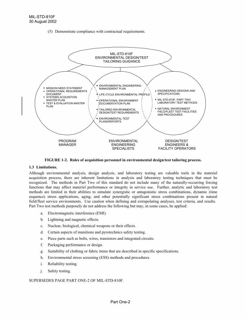
b. This document supports the functions of three different groups of personnel involved in the materielacquisition process. Each of these groups is critical to the goal of successfully incorporatingenvironmental considerations into materiel design, test, and evaluation. Although each group hasdifferent tasks to perform, none of these tasks can be isolated from the others in a successful acquisitionprogram. As shown on figure 1-2, this information is intended for the following:
(1) Materiel acquisition program managers among whose responsibilities is ensuring materiel willfunction as required in intended operational environments. (See paragraph 4.1 below.)
(2) Environmental engineering specialists (EES) who assist combat and materiel developers throughoutthe acquisition process to tailor their materiel designs and test designs to environmentalstresses/constraints expected during the materiel's service life. (See paragraph 4.2 below.)
(3) Design, test, and evaluation community analysts, engineers, and facility operators who meet userneeds by focusing on tailored designs and tests. (See paragraph 4.3 below, and Part Two of thisstandard.)
1.2 Application.The tailoring process described in this standard (i.e., systematically considering detrimental effects that variousenvironmental factors may have on a specific materiel system throughout its service life) applies throughout themateriel acquisition cycle to all materiel developed for military or commercial applications, includingnondevelopment item (NDI) procurements, procurements, or modifications of Allied systems or equipment, andcooperative development opportunities with one or more Allied nations to meet user and interoperability needs(DoDD 5000.1).
a. Part One lays out a disciplined, tailored approach for acquiring systems that will withstand the stressesof climatic, shock and vibration environments that they expect to see in their service lives. The basicprocess for acquiring materiel that satisfies users' needs from this environmental engineering viewpointis at figure 1-1.
b. Part Two also is an integral part of the environmental tailoring process. It contains tailoringinformation, environmental stress data, and laboratory test methods. The environmental data containedin the methods may help, but should not be used exclusively, to define environmental stresses thatmateriel will encounter throughout its service life. This will help engineers to tailor analyses and tests tospecific materiel and its defined life cycle. It is not valid to call out all of the methods in this standard ina blanket fashion for a materiel system; nor is it valid, once a method is determined appropriate, toregard the environmental stress data, test criteria, and procedures in the method as unalterable.
c. Guidance and test methods of this standard are intended to:
(1) Define environmental stress sequences, durations, and levels of materiel life cycles.
(2) Be used to develop analysis and test criteria tailored to the materiel and its environmental life cycle.
(3) Evaluate materiel performance when exposed to a life cycle of environmental stresses.
(4) Identify deficiencies, shortcomings, and defects in materiel design, materials, manufacturingprocesses, packaging techniques, and maintenance methods.
SUPERSEDES PAGE PART ONE-1 OF MIL-STD-810F.
MIL-STD-810F 30 August 2002
Par
(5) Demonstrate compliance with contractual requirements.
program managerenvironmental engineering specialistsdesign engineerstest engineersfacility operatorsMNS ORD TEMP EEMP LCEP OED DETP ETRtailoringfield/fleet testinglaboratory testing
FIGURE 1-2. Roles of acquisition personn
1.3 Limitations. Although environmental analysis, design analysis, acquisition process, there are inherent limitations irecognized. The methods in Part Two of this standfunctions that may affect materiel performance or inmethods are limited in their abilities to simulate synsequence) stress applications, aging, and other pofield/fleet service environments. Use caution when dPart Two test methods purposely do not address the fo
a. Electromagnetic interference (EMI).b. Lightning and magnetic effects. c. Nuclear, biological, chemical weapons or td. Certain aspects of munitions and pyrotechne. Piece parts such as bolts, wires, transistorsf. Packaging performance or design. g. Suitability of clothing or fabric items that ah. Environmental stress screening (ESS) methi. Reliability testing.
j. Safety testing.
SUPERSEDES PAGE PART ONE-2 OF MIL-STD-8
MISSION NEED STATEMENTOPERATIONAL REQUIREMENTSDOCUMENTSYSTEMS ACQUISITIONMASTER PLANTEST & EVALUATION MASTERPLAN
ENVIRONMENMANAGEMEN
LIFE CYCLE E
OPERATIONADOCUMENTAT
TAILORED ENDESIGN/TEST
ENVIRONMENPLANS/REPOR
MIL-ENVIRONMEN
TAILORIN
ENVIENGSP
PROGRAMMANAGER
t One-2
el in environmental design/test tailoring process.
and laboratory testing are valuable tools in the materieln analysis and laboratory testing techniques that must beard do not include many of the naturally-occurring forcingtegrity in service use. Further, analytic and laboratory testergistic or antagonistic stress combinations, dynamic (time
tentially significant stress combinations present in naturalefining and extrapolating analyses, test criteria, and results. llowing but may, in some cases, be applied:
heir effects. ics safety testing.
and integrated circuits.
re described in specific specifications.ods and procedures.
10F.
TAL ENGINEERINGT PLAN
NVIRONMENTAL PROFILE
L ENVIRONMENTION PLAN
VIRONMENTAL REQUIREMENTS
TAL TESTTS
ENGINEERING DESIGNS ANDSPECIFICATIONS
MIL-STD-810F, PART TWOLABORATORY TEST METHODS
NATURAL ENVIRONMENTFIELD/FLEET TEST FACILITIESAND PROCEDURES
STD-810FTAL DESIGN/TESTG GUIDANCE
RONMENTALINEERING
ECIALISTS
DESIGN/TESTENGINEERS &
FACILITY OPERATORS
MIL-STD-810F30 August 2002
Part One-3
2. APPLICABLE DOCUMENTS2.1 General. The documents listed in this paragraph are referenced in Part TWO of this standard. There are other documentscited in Part TWO of this standard that are recommended for additional information or as examples. While everyeffort has been made to ensure the completeness of this list, document users are cautioned that they should considerall specified requirements documents and tasks cited in paragraph 4 of this standard.
2.2 Government documents
2.2.1 Specifications, standards, and handbooks. The following specifications, standards, and handbooks forms a part of this document to the extent specified herein. When applying a portion of this standard that contains one of these references, cite the particular edition of thedocument that is listed in the current Department of Defense Index of Specifications and Standards (DoDISS), or inthe DoDISS that was in effect at the time of solicitation. Unless otherwise specified, the issues of these documentsare those listed in the issue of the DoDISS and supplement thereto, cited in the solicitation (see paragraph 6.2).
SPECIFICATIONS
MIL-S-901 Shock Tests, H.I. (High Impact) Shipboard Machinery, Equipment, and Systems, Requirements for
STANDARDS
MIL-STD-331 Fuze and Fuze Components, Environmental and Performance Tests for
MIL-STD-882 Standard Practice for System Safety
HANDBOOKS
MIL-HDBK-310 Global Climatic Data for Developing Military Products
(Copies of the above documents are available from the Document Automation and Production Service, Building4/D, 700 Robbins Avenue, Philadelphia PA 19111-5094; http://astimage.daps.dla.mil/online/new/.)
2.2.2 Other government documents.The following other Government documents and publications form a part of this document to the extent specifiedherein. Unless otherwise specified, the issues are those cited in the solicitation.
DIRECTIVES, INSTRUCTIONS, AND MANUALS
DoDD 5000.1 The Defense Acquisition SystemDoDI 5000.2 Operation of the Defense Acquisition SystemDoD 5000.2-R Mandatory Procedures for Major Defense Acquisition Programs (MDAPS) and Major
Automated Information System (MAIS) Acquisition Programs(Copies of the above documents may be downloaded from www.deskbook.osd.mil.)
PUBLICATIONS
AR 70-38 Research, Development, Test and Evaluation of Materiel for Extreme Climatic Conditions
(Copies of the above document are available from the U.S. Army Publications Distribution Center, 1655 WoodsonRd., St. Louis MO 63114-6181; telephone [314] 263-7305.)
2.3 Non-government documents. The following documents form a part of this document to the extent specified herein. Unless otherwise specified,the issues of the documents that are DoD adopted are those listed in the issue of the DoDISS cited in thesolicitation. Unless otherwise specified, the issues of documents not listed in the DoDISS are the issues of thedocuments cited in the solicitation (see 6.2).
SUPERSEDES PAGE PART ONE-3 OF MIL-STD-810F.
MIL-STD-810F 30 August 2002
Part One-4
STANAG 2895 Extreme Climatic Conditions and Derived Conditions for Use in Defining Design TestCriteria for NATO Forces Materiel
STANAG 4242 Vibration Tests for Munitions Carried in Tracked VehiclesSTANAG 4370 Environmental TestingQSTAG 360 Climatic Environmental Conditions Affecting the Design of Military MaterielAECTP 100 Allied Environmental Conditions and Test Publication (AECTP) 100, Environmental
Guidelines for Defence Materiel (under STANAG 4370)AECTP 200 Allied Environmental Conditions and Test Publication (AECTP) 200, Environmental
Conditions (under STANAG 4370)AECTP 300 Allied Environmental Conditions and Test Publication (AECTP) 300, Climatic
Environmental Tests (under STANAG 4370)AECTP 400 Allied Environmental Conditions and Test Publication (AECTP) 400, Mechanical
Environmental Tests (under STANAG 4370)(Copies of the above documents are available from the Document Automation and Production Service, Building4/D, 700 Robbins Avenue, Philadelphia PA 19111-5094; http://astimage.daps.dla.mil/online/new/.)
AMERICAN NATIONAL STANDARDS INSTITUTE (ANSI)
National Conference of Standards Labs (NCSL)
ANSI NCSL Z540-1 General Requirements for Calibration Laboratories and Measuring and Test Equipment
INTERNATIONAL ORGANIZATION FOR STANDARDIZATION (ISO) STANDARDS
ISO 10012-1 Quality Assurance Requirements for Measuring Equipment - Part I: MeteorologicalConfirmation System for Measuring Equipment First Edition
(Copies of the above documents are available from American National Standards Institute (ANSI), 25 West 43rdStreet, 4th Fl, New York NY 10036-7406 ; telephone [212] 642-4900; www.ansi.org.)
2.4 Order of precedence.In the event of a conflict between the text of this document and the references cited herein, the text of this documenttakes precedence. Nothing in this document, however, supersedes applicable laws and regulations unless a specificexemption has been obtained.
3. DEFINITIONS.
3.1 Terms.
This terminology section is meant to define the general terminology as it is used in this standard. In certain casesthe terminology use may be somewhat different from its use in the general engineering community. No attempt hasbeen made to be complete, therefore limiting the glossary to such terms as are found in the standard and that areimportant to the application of the standard. Terminology unique to a particular method is defined, as appropriate,in that method.
NOTE: A continuation of this terminology section that contains terminology more closely related to the dynamic(mechanical) test methods such as vibration, shock, gunfire vibration, etc., is in Part One Appendix D.
a. Accelerated test. A test designed to shorten the controlled environmental test time with respect to theservice use time by increasing the frequency of occurrence, amplitude, duration, or any combination ofthese of environmental stresses that would be expected to occur during service use.
b. Aggravated test. A test in which one or more conditions are set at a more stressful level than themateriel will encounter during service use.
SUPERSEDES PAGE PART ONE-4 OF MIL-STD-810F.
MIL-STD-810F30 August 2002
Part One-5
c. Ambient environment. The conditions, either outdoor or confined (e.g., temperature and humidity), thatcharacterize the air or other medium that surrounds materiel.
d. Climatic categories. Specific types of world climates which materiel is designed to withstand duringoperation, storage, and transit. See Part One, Appendix C, table C-I and figure C-1.
e. Combat developer. Military specialist concerned with training, doctrine, and materiel needsdocumentation.
f. Critical threshold value. The level of an environment forcing function that degrades the capability ofmateriel significantly or requires degradation prevention measures be taken.
g. Cumulative effects. The collective consequences of environmental stresses during the life cycle ofmateriel.
h. Engineering judgment. Expert opinion based on engineering education and experience, especially in thearea in which the judgment is made.
i. Environmental analysis. Technical activity covering an analytical description of the effects that variousenvironments have on materiel, subsystems, and component effectiveness.
j. Environmental conditions. (See Forcing function (environment).)k. Environmental engineering. The discipline of applying engineering practices to the effects that various
environments have on materiel effectiveness.l. Environmental engineering specialist (EES). A person or group of people skilled in one or more
environmental engineering areas. Areas include, but are not necessarily limited to: natural and inducedenvironments and their effects on materiel; expertise in measuring and analyzing in-serviceenvironmental conditions; formulating environmental test criteria; determining when environmentallaboratory tests are appropriate/valid substitutes for natural in-service environmental tests; andevaluating the effects of specific environments on materiel. (See paragraph 4.2.)
m. Environmental test. A structured procedure to help determine the effects of natural or inducedenvironments on materiel.
n. Environmental worthiness. The capability of materiel, subsystem, or component to perform its full arrayof intended functions in intended environments.
o. Equipment. For purposes of this standard, equipment includes the instrumentation, facilities, andsupport apparatus used to conduct or monitor tests. This does not include the test item itself or themateriel of which the test item is a sample or a part.
p. Forcing function (environment). A natural or induced physical environmental stress condition onmateriel that may affect its ability to function as intended or to withstand transit or storage during itsservice life. (Also referred to as an environmental condition or an environmental stress.)
q. Hermetic seal. A permanent, air-tight seal.r. Induced environment. An environmental condition that is predominantly man-made or generated by the
materiel platform. Also, refers to any condition internal to materiel that results from the combination ofnatural environmental forcing functions and the physical/chemical characteristics of the materiel itself.
s. In-service use. The anticipated use of materiel during its intended service use life.t. Integrated Product Team (IPT). A group of individuals from different professional disciplines and
organizations (government and industry) who work together on a product from concept throughproduction stages. Individuals who cover a discipline may change from stage to stage, but the disciplineis covered, and the information pertinent to that discipline is passed to the succeeding team member(s) inthat discipline.
u. Life Cycle Environmental Profile (LCEP). Design and test decision baseline document outlining real-world, platform-specific, environmental conditions that a specific materiel system or component willexperience during service-related events (e.g., transportation, storage, operational deployment/use) fromits release from manufacturing to the end of its useful life.
SUPERSEDES PAGE PART ONE-5 OF MIL-STD-810F.
MIL-STD-810F 30 August 2002
Part One-6
v. Life cycle profile. A time history of events and conditions associated with materiel from its release frommanufacturing to its removal from service, including demilitarization. The life cycle should include thevarious phases materiel will encounter in its life, such as: packaging, handling, shipping, and storageprior to use; mission profiles while in use; phases between missions such as stand-by or storage, transferto and from repair sites and alternate locations; and geographical locations of expected deployment.
w. Materiel. A commodity or set of commodities. A generic class of hardware designed to perform aspecific function.
x. Materiel developer. An agency or group of individuals involved in designing, testing, or evaluatingmateriel to meet developer performance requirements.
y. Mission profile. That portion of the life cycle profile associated with a specific operational mission.z. Operational worthiness. The capability of materiel, a subsystem, or component to perform its full array
of intended functions.aa. Parameter. Any quantity that represents a descriptive generalization of a certain characteristic physical
property of a system that has a certain value at a particular time.bb. Parameter level. The value of a physical property that documents the degree, extent, or level at which a
parameter exists at a given location at a given point in time, or the value to which a variable test controlis set (see test level).
cc. Platform. Any vehicle, surface, or medium that carries the materiel. For example, an aircraft is thecarrying platform for installed avionics items or transported or externally mounted stores. The land isthe platform for a ground radar set, for example, and a person for a man-portable radio.
dd. Platform environment. The environmental conditions materiel experiences as a result of being attachedto or loaded onto a platform. The platform environment is influenced by forcing functions induced ormodified by the platform and any platform environmental control systems.
ee. Program manager. The (Government) official who is in charge of the acquisition process for themateriel.
ff. Service life. Period of time from the release of materiel from the manufacturer through retirement andfinal disposition.
gg. Tailoring. The process of choosing design characteristics/tolerances and test environments, methods,procedures, sequences and conditions, and altering critical design and test values, conditions of failure,etc., to take into account the effects of the particular environmental forcing functions to which materielnormally would be subjected during its life cycle. The tailoring process also includes preparing orreviewing engineering task, planning, test, and evaluation documents to help ensure realistic weather,climate, and other physical environmental conditions are given proper consideration throughout theacquisition cycle.
hh. Test item. Specific materiel, a subsystem, or component being tested, including its container andpackaging materials, that is representative of the materiel being developed. A representative sample ofmateriel that is used for test purposes.
ii. Test level. The value at which a test condition is set or recorded. (Also, see parameter level.)jj. Test method. The criteria and procedures used to formulate an environmental test. Laboratory test
methods are identified by the environment (or combinations of environments) in Part Two of thisdocument.
kk. Test plan. A document that may include test procedures and test levels, failure criteria, test schedules,and operational and storage requirements.
ll. Test procedure. A sequence of actions that prescribes the exposure of a test item to a particularenvironmental forcing function or combination of environmental forcing functions, as well asinspections, possible operational checks, etc.
SUPERSEDES PAGE PART ONE-6 OF MIL-STD-810F.
MIL-STD-810F30 August 2002
Part One-7
mm. Virtual proving ground. A developing suite of tools, techniques, and procedures by which the testerwill verify, validate, test, and evaluate systems, simulators, and models by stimulating them withcomplex synthetic environments. These simulation-based tests should supplement and be validated bylive testing.
3.2 Acronyms.
Acronyms used in this document are defined below.
AECTP Allied Environmental Conditions and Test PublicationANSI American National Standards InstituteDETP Detailed Environmental Test PlanDoD Department of DefenseDoDD Department of Defense DirectiveDoDISS Department of Defense Index of Specifications and StandardsEEMP Environmental Engineering Management PlanEES Environmental Engineering SpecialistsEICL Environmental Issues/Criteria ListEMI Electromagnetic InterferenceESS Environmental Stress ScreeningETEMP Environmental Test and Evaluation Master PlanETR Environmental Test ReportIPT Integrated Product TeamISO International Organization for StandardizationLCEP Life Cycle Environmental ProfileMAIS Major Automated Information SystemMDAP Mandatory Procedures for Major Defense Acquisition ProgramMIL-HDBK Military HandbookMIL-STD Military StandardMNS Mission Need StatementNATO North Atlantic Treaty OrganizationNCSL National Conference of Standards LaboratoriesNDI Non-development ItemOED Operational Environment DocumentationOEDP Operational Environment Documentation PlanOEDR Operational Environment Documentation ReportORD Operational Requirements DocumentQSTAG Quadripartite Standardization Agreements (American, British, Canadian, and Australian)SAMP Systems Acquisition Management PlanSTANAG Standardization Agreements (NATO)TEMP Test and Evaluation Master Plan
SUPERSEDES PAGE PART ONE-7 OF MIL-STD-810F.
MIL-STD-810F30 August 2002
Part One-8
4. GENERAL PROGRAM GUIDELINES.
4.1 Program managers
4.1.1 Roles of the program manager.In the context of this standard, the program manager's primary role is to ensure environmental engineeringconsiderations are addressed systematically, thoroughly, and effectively at appropriate times throughout the materielacquisition process. The process for accomplishing this integration is diagrammed on figure 1-1. An associatedrole is to ensure environmental effects information is documented, available, and communicated from one programphase to another.
4.1.2 Guidance for program managers.a. DoD 5000-series documents call for a total systems approach through systems engineering, considering
all life cycle needs, including storage, transport, and operation in natural environments (DoDD 5000.1). Specifically, they call for a description of how performance in natural environmental conditionsrepresentative of the intended area of operations will be tested. This includes identifying test beds thatare critical to determine if developmental test objectives are achieved, taking into account such stressorsas temperature, vibration (random or sinusoidal), pressure, humidity, fog, precipitation, clouds,electromagnetic environment, blowing dust and sand, icing, wind conditions, steep terrain, wet soilconditions, high sea state, storm surge and tides, etc. (DoD 5000.2-R). The environmental tailoringprocess shown on figure 4-1 and the generalized life cycle environmental profile in figures 4-2a and b use systems engineering approaches, helping to ensure that system design and test criteria are tailored toenvironmental conditions within which materiel systems are to operate and that total ownership costsare reduced.
b. As indicated on figure 1-1, there may be times that the program manager has valid alternatives to testingactual hardware or hardware prototypes when conducting laboratory, development, or operational tests. These alternatives include, but are not necessarily limited to, using simulation to reduce the costsinvolved in producing and testing hardware prototypes, using coupon samples instead of entire systemswhen specific materials are the central acquisition issue, and using analytical procedures such asverification by similarity to systems already tested and approved. An environmental engineeringspecialist (EES) can aid program managers to establish an engineering basis for selecting suchalternatives. When these alternatives are selected, Task 401, Environmental Engineering ManagementPlan, must contain the rationale for their selection, including an explanation of expected cost savings,other benefits and risks to system effectiveness/safety. (See Part One, Appendix A, Task 401, andAppendix B, paragraph F.)
c. The following paragraphs, organized by major acquisition documents, capsulize environmental effectsinformation for program managers and serve as background information for design engineers, testengineers, and environmental engineering specialists. Appendix B provides detailed direction forprogram managers.
SUPERSEDES PAGE PART ONE-8 OF MIL-STD-810F.
MIL-STD-810F30 August 2002
Part
0
requirements documentstailoringplatform environmentnatural environmentforcing functionsinduced
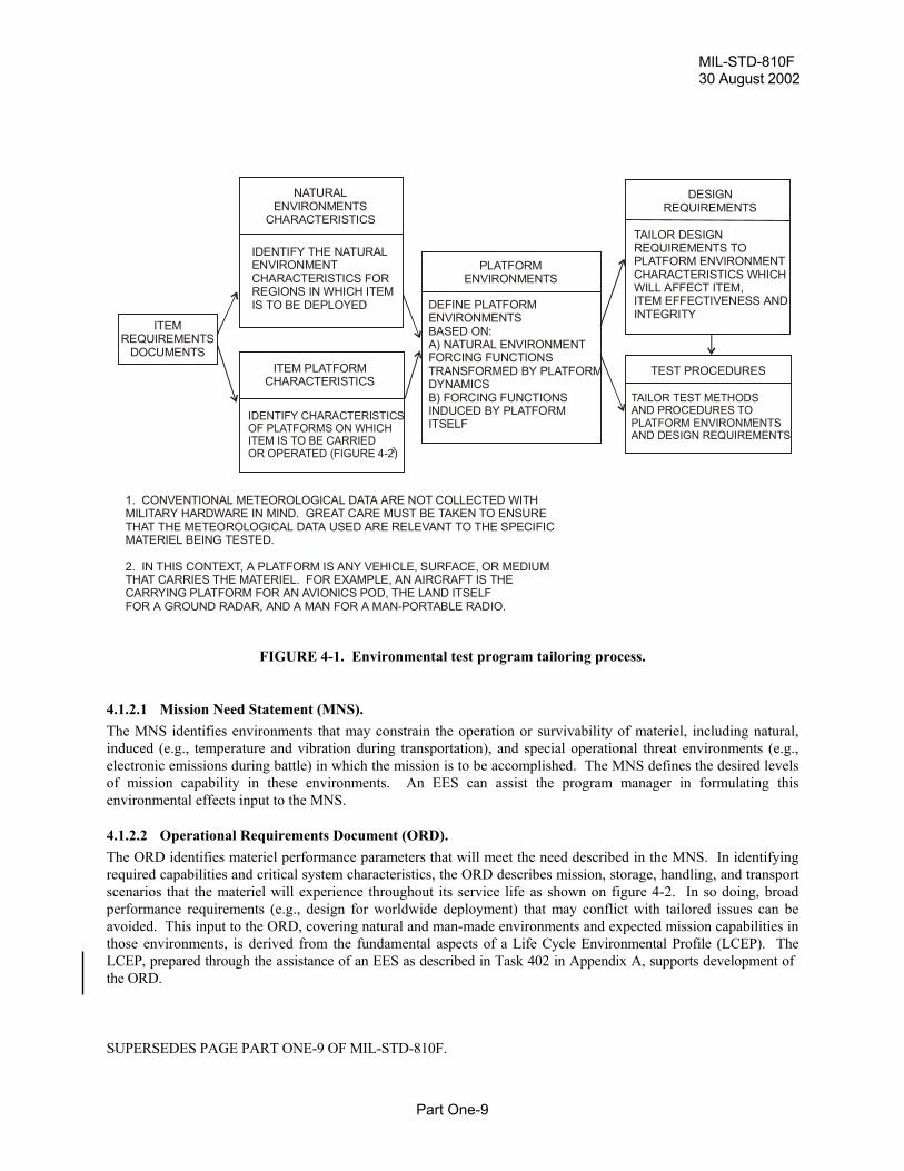
FIGURE 4-1. Environmental
4.1.2.1 Mission Need Statement (MNS).The MNS identifies environments that may constrain thinduced (e.g., temperature and vibration during transpoelectronic emissions during battle) in which the mission of mission capability in these environments. An EEenvironmental effects input to the MNS.
4.1.2.2 Operational Requirements Document (ORD)The ORD identifies materiel performance parameters tharequired capabilities and critical system characteristics, thscenarios that the materiel will experience throughout itperformance requirements (e.g., design for worldwide davoided. This input to the ORD, covering natural and mthose environments, is derived from the fundamental asLCEP, prepared through the assistance of an EES as descthe ORD.
SUPERSEDES PAGE PART ONE-9 OF MIL-STD-810F.
ITEMREQUIREMENTS
DOCUMENTS
NATURALENVIRONMENTS
CHARACTERISTICS
IDENTIFY THE NATURALENVIRONMENTCHARACTERISTICS FORREGIONS IN WHICH ITEMIS TO BE DEPLOYED
ITEM PLATFORMCHARACTERISTICS
IDENTIFY CHARACTERISTICSOF PLATFORMS ON WHICHITEM IS TO BE CARRIEDOR OPERATED (FIGURE 4-2)
DEENBAA) NFOTRDYB) FINDITS
1. CONVENTIONAL METEOROLOGICAL DATA ARE NOT CMILITARY HARDWARE IN MIND. GREAT CARE MUST BE TTHAT THE METEOROLOGICAL DATA USED ARE RELEVANMATERIEL BEING TESTED.
2. IN THIS CONTEXT, A PLATFORM IS ANY VEHICLE, SURTHAT CARRIES THE MATERIEL. FOR EXAMPLE, AN AIRCRCARRYING PLATFORM FOR AN AVIONICS POD, THE LANDFOR A GROUND RADAR, AND A MAN FOR A MAN-PORTAB
1
2
DESIGN
One-9
test program tailoring process.
e operation or survivability of materiel, including natural,rtation), and special operational threat environments (e.g.,is to be accomplished. The MNS defines the desired levelsS can assist the program manager in formulating this
.t will meet the need described in the MNS. In identifyinge ORD describes mission, storage, handling, and transport
s service life as shown on figure 4-2. In so doing, broadeployment) that may conflict with tailored issues can be
an-made environments and expected mission capabilities inpects of a Life Cycle Environmental Profile (LCEP). Theribed in Task 402 in Appendix A, supports development of
PLATFORMENVIRONMENTS
FINE PLATFORMVIRONMENTSSED ON:
ATURAL ENVIRONMENTRCING FUNCTIONSANSFORMED BY PLATFORMNAMICSORCING FUNCTIONSUCED BY PLATFORMELF
TEST PROCEDURES
TAILOR TEST METHODSAND PROCEDURES TOPLATFORM ENVIRONMENTSAND DESIGN REQUIREMENTS
REQUIREMENTS
TAILOR DESIGNREQUIREMENTS TOPLATFORM ENVIRONMENTCHARACTERISTICS WHICHWILL AFFECT ITEM,ITEM EFFECTIVENESS ANDINTEGRITY
OLLECTED WITHAKEN TO ENSURET TO THE SPECIFIC
FACE, OR MEDIUMAFT IS THE ITSELFLE RADIO.
MIL-STD-810F30 August 2002
Part One-10
4.1.2.3 Systems Acquisition Master Plan (SAMP).Program managers integrate environmental technical considerations (effects of various environments on systemperformance and reliability) into the SAMP. The mechanism for accomplishing this integration is provided in Task401 in the form of an Environmental Engineering Management Plan (EEMP) prepared through the assistance of anEES. The EEMP basically lays out a schedule for implementing the remaining environmental engineering tasks,Tasks 402 through 406.
4.1.2.4 Test and Evaluation Master Plan (TEMP).The TEMP includes plans for testing in natural (field/fleet) environments, simulated (laboratory) environments andvirtual proving ground (synthetic) environments. An EES assists the program manager in preparing the TEMP bydeveloping an Environmental Test and Evaluation Master Plan (ETEMP), the preparation of which may be mergedinto the Integrated Test Program Schedule. Appendix C provides information on the balance of field/fleet tests,laboratory tests, and modeling/simulation, and on the values chosen as design criteria or test criteria. Part Two of thisstandard provides details for developing laboratory test procedures. Component parts of the ETEMP are Tasks 402through 404. Thus, the ETEMP contains the following:
a. Life Cycle Environmental Profile (LCEP) displaying the series of events, and environmental conditionsderived from those events that materiel is expected to experience from manufacturing release to the endof its useful life. Include in TEMP the system description. (See Task 402.)
b. Operational Environment Documentation Plan (OEDP) outlining plans for obtaining specific natural orplatform environment data to be used in developing tailored environmental test criteria. The OEDP doesnot have to be included in the TEMP, but is a necessary subtask within the ETEMP for creating a validbasis for environmental test criteria. (See Task 403.)
c. Environmental Issues and Criteria List (EICL) containing fundamental environmental design and testcriteria derived from the tailoring process. Include criteria in the required technical and operationalcharacteristics of the TEMP. Include related critical issues in the TT&E or OT&E outline of the TEMP. (See Task 404.)
4.2 Environmental Engineering Specialists (EES).EES are government or industry professionals in the acquisition process whose experience allows them to supportprogram managers by helping to perform the tasks in Appendix A. Their backgrounds may span manyscientific/engineering disciplines. They already exist in Government and contractor agencies involved in theacquisition process (e.g., serving as design, test, and reliability engineers/scientists). Several EES of differentbackgrounds may work on an integrated product team (IPT) at one time or in sequence throughout the program,employed by or on contract to agencies of the services as appropriate at the time. Their work is documented andpassed on through the products of each successive task.
4.2.1 Roles of environmental engineering specialists.EES from agencies within and on contract to government agencies support program managers throughout theacquisition cycle. EES are assigned by agencies that are responsible for performing the tasks outlined on figure 1-1and explained in detail in Part One, Appendix A. EES should be involved early in the acquisition process, servingas critical sources of environmental effects expertise and as technical facilitators throughout the entire acquisitionprocess as part of an IPT. As shown on figure 1-2, EES form facilitating bridges among design and test needs ofprogram managers and technical procedures used by testers. The primary mechanisms for accomplishingenvironmental engineering goals are the tailoring tasks described below.
SUPERSEDES PAGE PART ONE-10 OF MIL-STD-810F.
MIL-STD-810F30 August 2002
Part One-11
4.2.2 Environmental engineering tailoring tasks
4.2.2.1 General.a. Environmental engineering tailoring tasks are the basic strategy and structure for integrating
environmental considerations into acquisition programs. The task sequence outlined on figure 1-1 isdesigned to meet the environmental effects integration called for in the DoD 5000-series documents. Toaccomplish this integration, EES personnel working for government or contractor staffs throughout theacquisition process help to perform these environmental engineering tasks to help create a scientificallysound, cost effective design and test program in the area of environmental effects. This process,including the hardware test alternatives indicated on figure 1-1, applies to all materiel developed for orintended to be used by the military or industry. Detailed task descriptions are in Appendix A.
b. As indicated in paragraph 4.1 above, the primary benefits of performing these tasks come from thetechnical information and structure they provide for the MNS, ORD, SAMP, and TEMP. Thisinformation covers natural and induced environmental conditions. The structure provides an orderlymeans of uncovering potentially significant environmentally-related failures during the acquisition cyclerather than after fielding (storage, transit, operational modes). The environmental engineering tasks,then, help reduce total ownership costs in terms of decreasing early system failures, reducing systemdowntime, saving repair/parts/logistic expenses, and even saving lives.
4.2.2.2 Preparing an Environmental Engineering Management Plan (EEMP), Task 401. The EEMP is the basic management schedule used to integrate environmental effects considerations into the SAMP.This integration helps to ensure materiel will be prepared for all environmental conditions to which it will besubjected during its life cycle. The EEMP identifies manpower, dollar estimates, timing and points of contactnecessary to complete the remaining tasks (402 through 406). As indicated on figure 1-1, paragraph 4.1.2 andAppendix B, paragraph F, there may be times that the program manager has valid alternatives, such as modeling andsimulation or other analytic techniques, to testing actual materiel or working prototypes. These alternatives arescheduled and justified in the EEMP. The EEMP is described in Part One, Appendix A, Task 401.
4.2.2.3 Developing an Environmental Test and Evaluation Master Plan (ETEMP).This plan is not a formal document, but is comprised of the products from three separate tasks (Tasks 402, 403, and404). Early in the acquisition process, initial work on these tasks helps build materiel need and performancerequirements documents by identifying basic environments in which the materiel will operate, and fundamentalissues to be addressed during the remainder of the acquisition process. These three tasks contribute to the TEMPwhen they are completed. See figure 1-1. The ETEMP contains basic guidance/background information not to beconfused with detailed test planning documents explained in Task 405.
4.2.2.3.1 Defining a Life Cycle Environmental Profile (LCEP), Task 402. The LCEP describes service-related events and environmental conditions that materiel will experience from itsrelease from manufacturing to the end of its useful life. The scope and structure are shown on figure 4-2 that servesas a generalized guide for developing LCEPs for acquisition programs. Tailor LCEPs to specific programs, treatingeach line in the body of figure 4-2 as a survey or questionnaire item to see if it applies to the specific program forwhich the LCEP is being developed. It may be useful to develop a questionnaire based on this LCEP format, takingcare to add unique, system-specific environmental stressors that may not appear in figure 4-2. Fundamental progressis required on this task early in the acquisition process to influence the MNS and the ORD. The completed LCEP isneeded later in the process to help system designers and evaluators build the TEMP. It is important to note that theLCEP does not specify design or test requirements. Rather, it serves as a tailored guide for deriving materieldesigns and test parameters through Tasks 403 and 404, based on performance requirements.
4.2.2.3.2 Developing Operational Environment Documentation (OED), Task 403. The OED task entails producing two documents. One is a plan for obtaining data that will serve as the basis fordesign and test criteria development. The other is a report that contains those plans and the resulting data. Theplan, the Operational Environment Documentation Plan (OEDP), provides for two types of data. First, it containsplans for securing data that have been collected previously and are still valid for developing the materiel's designand test criteria. Second, it contains plans for collecting data not available currently, describing how to obtain thoseenvironmental data under realistic operating or field conditions using actual or closely related systems/platforms.SUPERSEDES PAGE PART ONE-11 OF MIL-STD-810F.
MIL-STD-810F30 August 2002
Part One-12
The OEDP and the resulting data (existing and new data) form the Operational Environment Documentation Report(OEDR).
4.2.2.3.3 Developing an Environmental Issues/Criteria List (EICL), Task 404. The EICL is developed from the LCEP and OEDR. It contains a list of tailored issues and criteria, complete withappropriate criterion levels for the materiel being acquired. Also, it includes rationale and assumptions for howenvironmental effects issues and criteria were derived. This rationale aids designers, developers, and assessors asthey revise criteria when materiel deployment concepts and designs change.
4.2.2.4 Preparing a Detailed Environmental Test Plan (DETP), Task 405. Developers, evaluators, assessors, and testers prepare detailed environmental test and evaluation plans in variouslevels of detail (e.g., Independent Evaluation Plans through Detailed Test Plans), consulting with on-board EES asnecessary. These detailed plans serve as the primary means for calling out specific laboratory and field tests, testsites, instrumentation, procedures, and criterion levels for environmental tests. The DETP may stand alone as anenvironmental test planning document or may appear as a subset of a larger test plan. Quite often, the highest levelof detail in these plans appears in standard test procedures referenced in those plans. For environmental laboratorytests, detailed methods are in Part Two of this standard.
4.2.2.5 Preparing an Environmental Test Report (ETR), Task 406. Environmental test reports are produced at various points in the acquisition process. Specifications for conductingdevelopment and operational tests and formats for resulting reports are provided by development and operationaltest agencies. This task pertains mainly to the results of materiel tests performed in environmental testinglaboratories. The ETR defines the test purpose, lists test issues/criteria, lists or describes testequipment/facilities/instrumentation, explains the test design/set-up, contains detailed test data/logs, provides failureanalyses, and interprets test results. The laboratory ETR is appropriate for design evaluation tests, operationalworthiness tests, and qualification tests. Data from these laboratory tests serve as early warnings of unanticipateddeviations from performance requirements. They support failure analyses and corrective actions related to the abilityof materiel to withstand specific environmental conditions. These laboratory test data do not serve as substitutes fordevelopment or operational tests conducted in natural field/fleet environments.
4.3 Design and Test Engineers and Facility Operators.4.3.1 Roles of design engineers. Design engineers conduct engineering analyses that predict responses of materiel to the stresses of theenvironmental life cycle. These analyses are used to prepare materiel designs that incorporate necessary resistancesto environmental stresses, to modify test criteria to account for factors that cannot be fully accounted for inlaboratory testing, and to interpret test results during failure analyses and redesign.
4.3.2 Roles of test engineers/facility operators.Test engineers develop test implementation plans/instructions that are carried out by other engineers or facilityoperators. Facility operators conduct tests according to direction established in system test planning and assessmentdocuments and specific instructions prepared by test engineers/scientists who base their procedures on theenvironmental tailoring process. As a result of the tailoring process, laboratory testers will conduct only those teststhat are appropriate, using exposure levels that will be neither too high nor too low because they will have beenestablished according to the environments and levels that the materiel would be expected to see throughout itsservice life. In the same manner, field/fleet testers will conduct tests in those natural environments in which themateriel is expected to operate.
4.3.3 Guidance for design and test engineers and test facility operators.4.3.3.1 Natural environment (field/fleet) testing. Plan for and conduct natural environmental field/fleet tests, incorporating the principles of environmental tailoringinformation into established field/fleet procedures and facilities.4.3.3.2 Laboratory testing. Plan for and conduct laboratory tests according to the tailoring information above and specific guidelines below inPart One, plus specific guidelines in each method of Part Two of this standard.
SUPERSEDES PAGE PART ONE-12 OF MIL-STD-810F.
MIL-STD-810F30 August 2002
Part One-15
5. GENERAL LABORATORY TEST METHOD GUIDELINES.NOTE: Safety is an inherent concern in all test programs. Specific concerns are addressed in appropriate TestMethods. Guidelines to establish a materiel safety program are contained in MIL-STD-882.
5.1 Standard ambient test conditions.When the term, "standard ambient" is specified in the Methods of this standard, use the values shown below. If theterm is not used and no specific values are called for in the Test Method or the materiel specification, conduct itemtests (e.g.; pre-, during, and post-test) at standard ambient conditions.
Temperature: 25°C ± 10°C (77°F ± 18°F)Relative humidity: 20 to 80%Atmospheric pressure: Site pressure
NOTE: Every effort has been made to use metric units throughout this document. The initial figures are followedby U.S. units in parentheses, but these conversions are not usually repeated throughout this document.
5.2 Tolerances for test conditions. Unless otherwise specified, adhere to the test condition tolerances shown below for the following parameters. Anytolerance shown as ±X following a specified value is intended to mean the specified value is what is intended but,because of instrumentation or measurement inaccuracies, a slight deviation is acceptable but not outside of thetolerance.
a. Test section air temperature. Surround the test item totally by an envelope of air (except at necessarysupport points), considering boundary effects. Keep the air temperature uniform in the immediatevicinity of the item. To ensure that the test item is bathed in the required air temperature, placeverification sensors at representative points around the entire item and as close to the test item aspossible but not so the airstream temperature is affected by the test item temperature. Keep thesetemperatures within ±2°C (3.6°F) of the required test temperature. Ensure the air temperature gradientacross the item does not exceed 1°C (2°F) per meter or a maximum of 2.2°C (4°F) total (test itemnonoperating). Wider temperature tolerances are acceptable in situations such as:
(1) For large items with a volume greater than 5 m3, the temperature tolerance can be ±3°C. Justify anylarger tolerance and obtain approval for its use from the procuring activity.
(2) For required temperatures greater than 100°C, the temperature tolerance can be ±5°C. Specify theactual tolerance achieved.
b. Pressure. ±5 percent of the value or ±200 Pa, whichever is greater.
c. Humidity. Keep relative humidity at the chamber control sensor to ±5 percent RH of the specified value.
d. Vibration amplitude.
Sinusoidal Peak ±10 percentRandom See Method 514.5.
e. Vibration frequency. Measure vibration frequency of 25 Hz and above to an accuracy of ±2 percent. Below 25 Hz, use ±1/2 Hz.
f. Acceleration. See the tolerances specified in the test methods.
g. Time. Control time (e.g., test durations and data gathering intervals) within 5 minutes for total testdurations greater than 8 hours, and within 1 percent of the specified value for durations or intervals of8 hours or less, unless the nature of the test requires greater accuracy.
SUPERSEDES PAGE PART ONE-15 OF MIL-STD-810F.
MIL-STD-810F1 January 2000
Part One-16
h. Air velocity. Maintain within 10 percent of specified value.
i. Water purity. See paragraph 5.16.
5.3 Test instrumentation
5.3.1 Suitability for environment. Ensure the sensors and instrumentation to be used for recording environmental conditions and responses are suitablefor the intended environments. (For example, accelerometers used in a combined high temperature/vibration testcould give erroneous readings if not designed for high-temperature use.)
5.3.2 Calibration. Prior to and following each test, verify the accuracy of instruments and test equipment used to control or monitorthe test parameters. Calibration intervals must meet the guidelines of ANSI NCSL Z540-1 or ISO 10012-1 to thesatisfaction of the procuring activity. All instruments and test equipment used in conducting the tests in thisdocument should:
a. Be calibrated to laboratory standards, traceable to the National Standards via primary standards.
b. Have an accuracy at least equal to 1/3 the tolerance of the variable to be measured. In the event ofconflict between this accuracy and guidelines for accuracy in any one of the Test Methods of thisstandard, the latter governs.
5.4 Stabilizing test temperature. Temperature stabilization is generally important to ensure reproducible test conditions. Stabilizing test itemelements critical for operational requirement (i.e.; components, subassemblies, etc.) normally is more important thanstabilizing temperatures of structural members. The following information is based on this intent.
5.4.1 Test item operating. Unless otherwise specified, operating temperature stabilization is attained when the temperature of the functioningpart(s) of the test item considered to have the longest thermal lag is changing at a rate of no more than 2.0°C (3.6°F)per hour.
5.4.2 Test item non-operating. Unless otherwise specified, non-operating temperature stabilization is attained when the temperature of thefunctional part(s) of the test item considered to have the longest thermal lag reaches a temperature that is within thetemperature tolerance of the air surrounding the test item. Structural or passive members are not normallyconsidered for stabilization purposes. When adjusting temperatures, the temperature of the chamber air may beadjusted beyond the test condition limits to reduce stabilization time, provided the extended temperature does notinduce a response temperature beyond the test item's temperature limits.
5.5 Test sequence. Base the specific sequence on the item, its intended situation-dependent use, available program assets, andanticipated synergetic effects of the individual test environments. In defining a life cycle sequence of exposures,consider recurring exposure(s) that might reasonably occur during service use. In most cases there is no singledefined sequence. See Appendix C of Part One for additional information.
a. Use the anticipated life-cycle sequence of events as a general sequence guide. However, experience hasshown definite advantages to performing certain tests immediately before, in combination with, orimmediately following other tests. Where these advantages have been identified in the information inthe Test Methods, follow the test sequence. Use other sequences and combinations consistent with good
REPRINTED WITHOUT CHANGE.
MIL-STD-810F1 January 2000
Part One-17
tailoring practices with the permission of the acquisition agency. With the exception of informationprovided in the individual methods, do not alter test sequences to ease the effects of the tests.
b. Relate cumulative effects on performance and durability of a materiel item to a test sequence thatstresses materiel in the proper order according to its mission profile (see Part One, figure 4-2 as anexample). Developing such a test sequence requires communication among the test sponsor, the tester,the evaluator, and the end user early and often to ensure a trackable, reliable, and realistic test effort.
5.6 Test Level Derivation. Derive specific test levels, ranges, rates, and durations from data that occur on identical or appropriately similarmateriel that is situated on platforms under similar natural environmental conditions (see Appendix A, Task 403,paragraph 403.2.1). When data from actual situations are not available or cannot be obtained nor estimated easily,tailor the test characteristics using the information found in specific methods.
5.7 Pretest Information for Facility Operators. Provide the following (in addition to any information required in the individual test methods):
a. Test facilities and instrumentation.
b. Required test procedure(s).
c. Critical components, if applicable.
d. Test duration.
e. Test item configuration.
f. Test level, duration, and method of stress application.
g. Location of instrumentation/sensors, e.g., thermocouples, transducers.
h. Test item installation details (including mounting provisions, orientation, interconnections, etc.).
i. Cooling provisions, if appropriate.
5.8 Test Setup.
5.8.1 Installing the test item in test facility.Unless otherwise specified, install the test item in the test facility in a manner that will simulate service use to themaximum extent practical, with test connections made and instrumentation attached as necessary.
a. To test the effectiveness of protective devices, ensure plugs, covers, and inspection plates used inservicing are in whatever position is appropriate for the test and in their normal (protected orunprotected) mode during operation.
b. Make electrical and mechanical connections normally used in service, but not required for the test beingperformed (e.g., tests of items not running) with dummy connectors installed (connected and protectedas in field/fleet use) so that all portions of the test item will receive a realistic test.
c. If the item to be tested consists of several separate units, these units may be tested separately, providedthe functional aspects are maintained as defined in the requirement’s document. If units are being testedtogether and the mechanical, electrical, and RF interfaces permit, position units at least 15 cm (6 inches)from each other or from the test chamber surfaces to allow for realistic air circulation.
d. Protect test items from unrelated environmental contaminants.
5.8.2 Test item operation. Operate the test item in the most representative operating modes (from performance and thermal standpoints) usingduty cycles and durations that represent service use.
REPRINTED WITHOUT CHANGE.
MIL-STD-810F30 August 2002
Part One-18
5.9 Pretest Baseline Data. Before environmental exposure, operate the test item under standard ambient conditions (see paragraph 5.1) toensure the test item is operating properly and to obtain baseline performance data. Include the followinginformation in the pretest documentation:
a. Background data of each item:
(1) Item nomenclature, model, serial number, manufacturer, etc.(2) General appearance/condition.(3) Specific physical anomalies.(4) Environmental test history of the specific item.
b. Collect pretest data on the functional parameters that will be monitored during and after eachenvironmental test. Use functional parameters and operational limits specified in the materielspecification or requirements document. If such specifications are not provided, establish and applyappropriate parameters/limits for the pretest, the main test, and the post test.
5.10 Information During Test (for inclusion in the Test Report). a. Performance check. Monitoring and recording of test items’ critical performance parameters is required
before and after all tests. Monitoring of performance parameters is not required during non-operationaltests such as storage and transportation. Monitoring of performance parameters during operational testsis strongly suggested. Where cost concerns preclude monitoring during an operational test,consideration should be given to the consequences of undetected, intermittent failures.
b. Test facility. Maintain a record of environmental conditions applied to the test item.
c. Test item response. Maintain a record of test item response to applied environmental forcing functions.
5.11 Interrupted Tests. For the purpose of standardization and valid testing, and unless otherwise specified in the individual methods, applythe following procedures when a test is interrupted. Explain test interruptions in the test report, and any deviationfrom the following information.
5.11.1 In-tolerance interruptions. Interruption periods during which the prescribed test conditions remain in tolerance (e.g., power interruptions thatdo not affect chamber temperature) do not constitute a test interruption. Therefore, do not modify the test durationif exposure to proper test levels was maintained during the ancillary interruption.
5.11.2 Out-of-tolerance interruptions for methods 503, 506, 510, 511, 514, 515, 516, 517, 519, 522, and 523. A logic diagram for these methods is on figure 5-1.
a. Undertest. If test condition tolerances fall below the minimum tolerance value (i.e., environmental stressless severe than specified) resulting in an undertest condition, the test may be resumed (afterreestablishing prescribed conditions, except as noted in the individual methods) from the point at whichthe test condition fell below the lower tolerance level. Extend the test to achieve the prescribed testcycle duration.
b. Overtest. If an overtest condition occurs, the preferable course of action is to stop the test and start overwith a new test item. But, as shown on figure 5-1, if there is no damage to the test item, continue thetest, realizing that if the item fails the test from this point on or fails subsequent tests, you have a "NOTEST" unless it can be shown that the overtest condition had no effect on the test item. Overtestconditions can damage the test item and cause subsequent failures that may not have occurred otherwise,thus failing a test item because of an invalid test. However, if damage resulting directly from an overtestoccurs to a test item component that has absolutely no impact on the data being collected, and it isknown that such damage is the only damage caused by the overtest (e.g., rubber feet on bottom of a testitem melted by high temperature where those feet have no impact on the performance of the test item),the test item can be repaired and the test resumed and extended as in the undertest condition.
SUPERSEDES PAGE PART ONE-18 OF MIL-STD-810F.
MIL-STD-810F30 August 2002
Part One-19
Coordinate with the customer before repairing and continuing to test an item after it has been overtested.This coordination is aimed at preventing customer objections if the test item fails during the remainder ofthe test program (claims that the test was invalid past the point of the overtest because the overtestcaused undiscovered damage to a critical component).
5.11.3 Out-of-tolerance interruptions for methods 500, 501, 502, 504, 505, 507, 508, 509, 512, 513, 518, 520,and 521. Each of these methods contains information for handling out-of-tolerance test of interruptions. Analyze any suchinterruption carefully. If the decision is made to continue testing from the point of interruption, to restart the lastsuccessfully completed test cycle, or to restart the entire test with the same test item, and a failure occurs, it isessential to determine the effects of having interrupted or extended the test.
5.12 Combined Tests. Combinations of tests may represent the effects of the environment more realistically than a series of single tests. Combined environment testing is encouraged when these conditions may be expected in operational environments.
5.13 Post-test Data. After completing each environmental test, examine the test item in accordance with the materiel specifications. Operate the test item when appropriate for obtaining post-test data. Compare the results with the pretest dataobtained in accordance with paragraphs 5.8 and 5.10. Include the following information in the post-test record andreport:
a. Test item identification (manufacturer, model/serial number, etc.).
b. Test equipment identification, including accessories.
c. The actual test sequence (program) used.
d. Deviation from the planned test program (including explanation).
e. Performance data collected on the same parameters at the same operational levels as those of the pretest(including visual examination results and photographs, if applicable).
f. Test item identification (manufacturer, model/serial number, etc.).
g. Room ambient test conditions recorded periodically during test period.
h. Other data specified in individual methods or requirements document(s).
i. Initial failure analyses, if applicable.
j. A signature and date block for the test engineer/technician to certify the test data.
SUPERSEDES PAGE PART ONE-19 OF MIL-STD-810F.
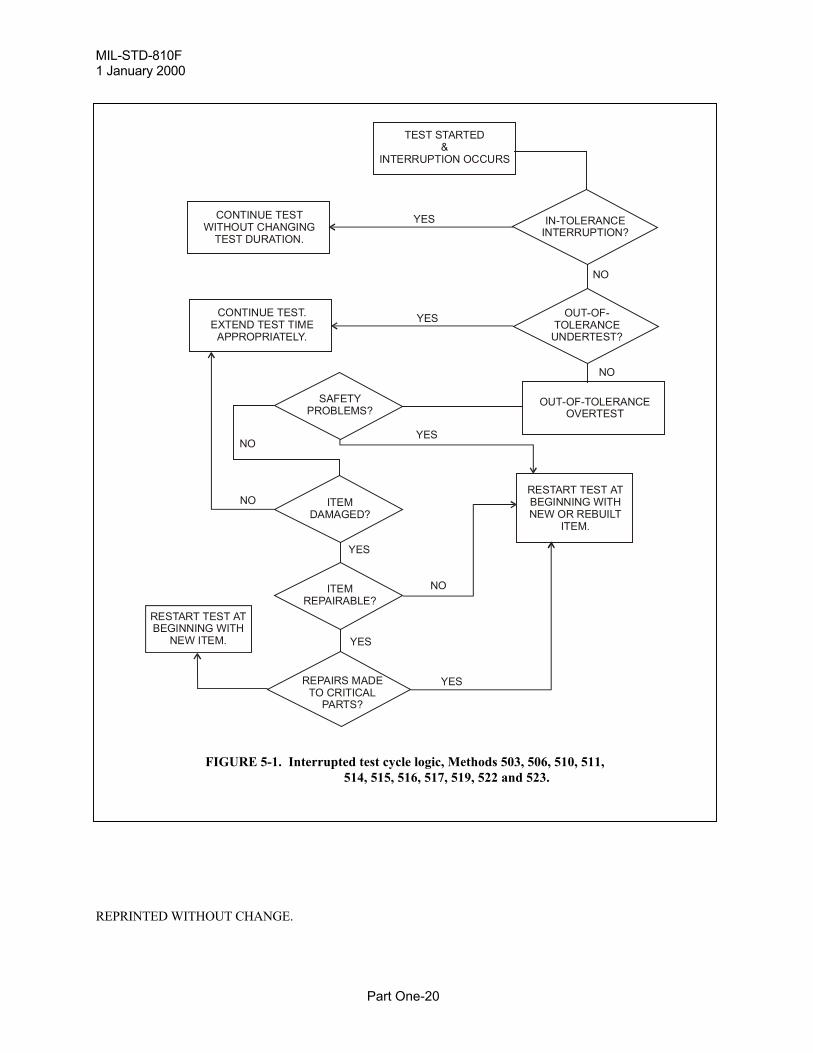
MIL-STD-810F1 January 2000
Part One-20
interrupted testsdamagesafetyovertestundertest
REPRINTED WITHOUT CHANGE.
TEST STARTED&
INTERRUPTION OCCURS
YES IN-TOLERANCEINTERRUPTION?
NO
OUT-OF-TOLERANCE
UNDERTEST?
NO
OUT-OF-TOLERANCEOVERTEST
RESTART TEST ATBEGINNING WITHNEW OR REBUILT
ITEM.
YES
YES
YES
NO
REPAIRS MADETO CRITICAL
PARTS?
ITEMREPAIRABLE?
ITEMDAMAGED?
SAFETYPROBLEMS?
NO
NO
YES
YESCONTINUE TEST.EXTEND TEST TIME
APPROPRIATELY.
CONTINUE TESTWITHOUT CHANGING
TEST DURATION.
RESTART TEST ATBEGINNING WITH
NEW ITEM.
FIGURE 5-1. Interrupted test cycle logic, Methods 503, 506, 510, 511,514, 515, 516, 517, 519, 522 and 523.
MIL-STD-810F30 August 2002
Part One-23
degradation. Other minimum intervals may be set to capture transient events that may occur at any timeduring the test.
6. NOTES.(This paragraph contains information of a general or explanatory nature that may be helpful.)
6.1 Intended use. This standard is intended to organize and standardize the approach within the materiel acquisition process forconsidering how environmental stresses affect materiel design, test, and evaluation. It emphasizes tailoring materielto withstand the stresses it is intended to experience during its life cycle, and testing such materiel accordingly. Theintended result is to eliminate over- and under-designed/tested materiel with respect to environmental stresses, toensure environmental considerations are addressed systematically, to ensure test plans are tailored realistically aswell as thoroughly, to ensure test execution adheres to tailored test plans, and to ensure test reports are complete andmeaningful.
6.2 Issue of DoDISS. When this standard is used in acquisition, the applicable issue of the DoDISS must be cited in the solicitation (seeparagraphs 2.2.1 and 2.3).
6.3 Subject term (key word) listing. (Also see Subject Index, page Index-1.)AccelerationAcidic AtmosphereAcoustic NoiseClimatic EnvironmentDustEnvironmental Life CycleEnvironmental Test ProceduresEnvironmental Test ReportExplosive AtmosphereFluid ContaminationFungusGunfire VibrationHumidityImmersionInduced EnvironmentLow Pressure (Altitude)Natural EnvironmentRainSalt FogSandShockSolar RadiationTemperatureTemperature ShockVibration
6.4 International Standardization Agreement. Certain provisions of this standard are the subject of international standardization agreementsSTANAG’s 2895, 4242, and 4370. When proposed amendments, revisions, or cancellation of this standard willmodify the international agreement concerned, the Preparing Activity will take appropriate action throughinternational standardization channels, including departmental standardization offices, to change the agreement ormake other appropriate accommodations.
SUPERSEDES PAGE PART ONE-23 OF MIL-STD-810F.
MIL-STD-810F30 August 2002
Part One-24
6.5 Changes from previous issue. This document is a complete rewrite of MIL-STD-810E. Due to the extensive modifications, asterisks or verticallines are not used to identify changes from the previous issue. Changes to MIL-STD-810F will be published inChange Notices.
Custodians: Preparing activity: Army – TE Air Force – 11 Navy – AS (Project ENVR-0050) Air Force – 11
Review activities: Army – AR, AT, AV, CE, CR, GL, HD, MI, MT, SM Navy – CH, EC, MC, OS, SH, YD Air Force – 13, 19
International interest (See paragraph 6.4.)
SUPERSEDES PAGE PART ONE-24 OF MIL-STD-810F.
MIL-STD-810F30 August 2002APPENDIX A
Part One A-3
TASK 401
ENVIRONMENTAL ENGINEERING MANAGEMENT PLAN (EEMP)
401.1 Purpose. The EEMP is basically an administrative document prepared by the program manager's staff orcontract personnel responsible to the program manager. It provides a schedule for integrating Tasks 402 through406 into the Systems Acquisition Master Plan (SAMP). By so doing, the EEMP lays out a viable and cost effectiveenvironmental effects program to help ensure that materiel will be designed and tested for all pertinentenvironmental conditions to which it will be subjected during its life cycle. The EEMP also outlines criticalenvironmental engineering technical and communications interfaces between the materiel developer and theprocuring agency.
401.2 Task description. As a minimum, perform the following subtasks and include subtask products in the EEMP:
a. Identify Government agencies and contracts that will include EES personnel to assist in organizing andexecuting environmental engineering tasks. Include list in EEMP.
b. Include in the EEMP the environmental engineering tasks listed below. Note that Tasks 402, 403, and404 comprise the Environmental Test and Evaluation Master Plan (ETEMP) which providesfundamental input to the MNS and ORD and detailed input to the TEMP (see Part One, figure 1-1 andparagraph 4.1.2.4).
(1) Task 402 - Life Cycle Environmental Profile (LCEP)
(2) Task 403 - Operational Environment Documentation (OED)
(3) Task 404 - Environmental Issues/Criteria List (EICL)
(4) Task 405 - Detailed Environmental Test Plans (DETP)
(5) Task 406 - Environmental Test Report (ETR)
(6) Other program-specific tasks as appropriate
c. Provide risk assessments for any tasks that are eliminated or curtailed, and for alternatives to testingactual hardware or prototypes. For example, if an analytical procedure, acceptance by similarity toanother system, coupon samples, or simulations are used in lieu of testing actual systems or prototypes,explain the cost savings, other benefits, and risks to system effectiveness/safety. Because the EEMP is aliving document, it may be changed at any time to accommodate such alternatives.
d. Develop schedules, milestones, and personnel requirements needed to accomplish these tasks.
e. Identify lines of communication among the specific developer and acquisition agency organizationalelements responsible for environmental engineering.
f. Develop methods/schedules for monitoring, assessing, reporting government and contractor progress ontasks; updating task products (e.g., profiles and plans), and for implementing corrective actions forproblems in developing and executing the EEMP, and include them in EEMP.
401.3 Details to be provided by the acquisition agency.
a. Complete description of the materiel to be developed and the scenarios associated with its intendedservice application(s).
b. Schedule and procedures for EEMP submittal.
c. Identification as a contract task or submittal.
d. Special conditions or restrictions.
SUPERSEDES PAGE PART ONE A-3 OF MIL-STD-810F.

MIL-STD-810F1 January 2000APPENDIX A
Part One A-4
THIS PAGE INTENTIONALLY BLANK
REPRINTED WITHOUT CHANGE.
MIL-STD-810F30 August 2002APPENDIX B
Part One B-1
APPENDIX B
DETAILED PROGRAM MANAGEMENT GUIDANCE
A. General. Materiel must perform adequately under all environmental conditions associated with its service life;withstand those conditions in transit and storage, and maintain the desired level of reliability after environmentallyharsh operation, storage, and transit. In order for this to happen, the effects that environmental conditions have onmateriel effectiveness and safety must be determined, considered, analyzed, and integrated into all aspects of theacquisition process as indicated in Part One, figures 4-1 and 4-2. The guidance provided here and throughout thisentire standard applies to the effects of environments on systems rather than the effects of systems on environmentalquality. Therefore, the thrust of this standard should not be confused with Environmental Impact programs thatfocus on how to preserve and protect flora and fauna from service personnel, their materiel, and their activities. Conversely, this standard pertains to the effects that environments have on materiel system effectiveness.
B. Environments of intended use.
1. Several sections of the DoD 5000-series on Defense Acquisition address environmental considerations,stressing that a system will be demonstrated in its intended environment (DoDI 5000.2). Unlike othertechnical areas (e.g., reliability, electromagnetic environmental effects, human factors, and environmentalquality), no single section of that series is devoted to addressing natural or induced environmental factors. Therefore, this Part One of MIL-STD-810F provides basic program procedures for integratingenvironmental factors into the materiel acquisition process. This integration is accomplished through inputto acquisition planning documents from the Mission Need Statement through the Test and EvaluationMaster Plan to detailed test and evaluation plans and reports.
2. Environmental factors, working separately and in various combinations, are known to affect operation,transit, and storage of materiel. The DoD 5000-series documents point out that these factors includeclimate (temperature, humidity, solar radiation, rain, snow, icing phenomena, wind, blowing sand, dust andsnow, ozone, freeze-thaw occurrences, fog, cloud ceiling height, and visibility); weather-relatedatmospheric obscurants (rain, snow, fog, cloud cover); terrain elements (slope, soil, and vegetation);induced elements (shock and vibration); and field/fleet conditions (obscurants, debris, emissions). Environmental Engineering Specialists (EES) are trained to assist acquisition personnel throughout theacquisition cycle to integrate these environmental concerns into requirements, design, test and evaluationdocuments, and procedures. See Appendix A of this document.
C. Balancing cost, schedule, and performance considerations. One of the basic policies governing defenseacquisition covers the need to translate operational needs into stable, affordable programs. The key to this is using aconcurrent systems engineering approach to help ensure reliable performance in all operational environments, whenrequired. This entails designing a product to perform its assigned mission over time in intended operationalenvironments and, at the same time, designing the system to survive non-operational environments (e.g., storage).D. Trade-off considerations. Evaluate the need to operate in extreme environments against other factors such ascost, technical feasibility, tactics, doctrine, and materiel platforms. Higher costs, logistical problems, andoperational difficulties associated with these environmentally rigorous areas could lead to selecting one of thefollowing:
1. Special materiel capable of operation in extreme environmental areas.
2. Special materiel solely for extreme environments.
3. Modification kits that adapt new standard materiel or previously type-classified materiel to such use.
4. Special design values that are more extreme than normal tailoring would suggest for materiel whose failureto operate would be life-threatening.
5. Special design for materiel that would be useless or dangerous after one-time exposure.
E. Testing materiel for environmental effects. Developmental and evaluation plans must consider environmentaleffects outlined in the life cycle environmental profile. Both chamber tests and field/fleet tests serve usefulpurposes.SUPERSEDES PAGE PART ONE B-1 OF MIL-STD-810F.
MIL-STD-810F 30 August 2002APPENDIX B
Part One B-2
Apply them at appropriate times during the acquisition cycle. Except for reasons of safety, chamber tests cannot besubstituted for field/fleet development tests because unknown synergistic/antagonistic effects from combined/induced environments cannot be built into chamber/laboratory test methods. An example where chamber testingmay be substituted for field/fleet testing is ammunition conditioning prior to test firing. Following are someguidelines for laboratory testing, natural field/fleet development testing and operational testing.
1. Laboratory testing. Conduct laboratory tests early in the development stage to screen materiel forenvironmentally caused problems that may degrade materials, performance, or reliability. Conductlaboratory tests according to the general tailoring guidance in Part One and the specific testing guidelinesin Part Two of this standard.
2. Natural field/fleet development testing. Conduct natural environmental field/fleet development tests todetermine the true effects of the real environment. This will allow system assessment ofsynergistic/antagonistic effects of natural environmental factors combined with human factors and inducedfactors such as shock/vibration, smoke/obscurants and electromagnetic interference. Use establishednatural climatic test centers and standard test procedures to obtain data that may be compared toprevious/following test data and to develop data bases that may be used for simulations.
3. Operational testing. Conduct operational testing in natural environments that are as realistic as possible. When operational testing cannot subject materiel to the desired ranges of environmental stresses anddeterioration that may be encountered during actual operation, storage, and transit, development testenvironmental effects data may be substituted for operational test environmental effects data.
F. Analytic alternatives to testing actual hardware. In some instances, there may be analytic alternatives to testingactual systems or hardware prototypes in laboratories or in field/fleet environments. An EES can help to establishan engineering basis for selecting and implementing such alternatives. When alternatives to testing actual hardwareor prototypes are chosen, Task 401, Environmental Engineering Master Plan, must contain the rationale for theirselection including an explanation of the cost savings, other benefits and risks to system effectiveness/safety. (SeePart One, paragraph 4.1.2.b; Appendix A, Task 401; and Appendix B, paragraph F.) Analytic alternatives include,but are not necessarily limited to the following.
1. Modeling and simulation. Modeling and simulation (M&S) is useful in representing conceptual systemsthat do not exist, nascent technologies, and extant systems that cannot be subjected to actual environmentsbecause of safety requirements or the limitations of resources and facilities (DoDI 5000.2). Modeling andsimulation techniques should be used only to the extent that their predictive validities have been verified.They are not intended to be substitutes for tests in natural field/fleet environments. Simulation can reducehigh costs involved in producing and testing hardware prototypes. Although artificial intelligence andsoftware simulations may be integral parts of models, neither these types of data nor data from laboratorytests should be used to validate models. The most sound criteria for developing and validating models andsimulations come from real world, field/fleet data or knowledge bases. To that end, all fields of science andengineering can help to save costs through simulation by developing or contributing to lessons learned databases or knowledge bases that cover the entire domain of environmental effects (DoDD 5000.1). (SeeAppendix C, paragraph B, below.)
2. Testing coupon samples. In some instances, particularly in laboratory tests and natural field/fleetexposure/surveillance tests, there may be significant savings by using coupon samples instead of entiresystems when specific materials are the central acquisition issue.
3. Acceptance by similarity. In cases where materiel considered for testing is nearly identical to materielalready tested, and there is no reason to believe that the differences between them would pose anenvironmentally induced problem, the program manager may consider accepting the materiel by virtue ofits similarity to the similar materiel already accepted.
G. Type classification process. Environmental considerations influence the type classification process. Formateriel that is designated by the combat developer to be critical to combat success, type classification or fieldingmay be barred if environmental testing reveals that environmental effects were not considered adequately andincorporated in the design of the system. Additionally, successful system performance and reliability in naturalenvironments are listed as critical issues in Milestone III (production) decisions.
SUPERSEDES PAGE PART ONE B-2 OF MIL-STD-810F.
MIL-STD-810F30 August 2002APPENDIX C
Part One C-3
feet) will be only slightly warmer than that observed in an instrument shelter at about twice that height.1 Inwinter, such temperatures are likely to be in the same range as for the Basic Climatic Category. If materielis designed only for the hot climate, seek a specially tailored low outdoor ambient air temperature designvalue. Small portions of this area are sometimes subject to very high absolute humidity. However, in thesehot-wet areas, the highest outdoor ambient air temperatures and highest dew points do not occur at thesame time.
2. Basic Climatic Category. This includes the most densely populated and heavily industrialized parts of theworld as well as the humid tropics. The entire range of basic design conditions does not necessarily occurin any one place. Each single condition (high temperature, low temperature, high humidity) occurs in awide area. When taken together, the design values should be valid for materiel used throughout the area.
a. Humid tropic zone. Humid tropic areas are included in the Basic Climatic Category rather than beingconsidered an extreme category because humid tropic temperatures are moderate and their humiditylevels are equaled at times in some of the other mid-latitude areas. The features of the humid tropicsmost important for materiel system design are moderately high temperatures and high rainfallthroughout the year that spawn persistent high humidity and high flora and fauna diversity. Thesecombined environmental conditions greatly increase insect and microbiological damage and promotecorrosion more so than any other region of the world. This is important for DoD’s CorrosionPrevention and Control Program (DoD 5000.2-R).
b. Intermediate zone. These are mid-latitude areas that do not combine higher temperatures with higherhumidities throughout the year, and at the same time are not climatically extreme enough to meet theconditions for Hot nor Cold Climatic Categories. This zone includes the daily cycles shown in tableC-I, plus a condition known as "cold-wet" which can occur within the mild cold daily cycle at or nearthe freezing point (2 to -4°C (35 to 25°F)) with relative humidity tending toward saturation (100 to95% RH) and negligible solar radiation.
3. Cold and Severe Cold Climatic Categories. These areas include northern North America, Greenland,northern Asia, and Tibet. In the Cold Climatic Category, the temperature during the coldest month in anormal year may be colder than the Basic Climatic Category cold extreme of -32°C (-25°F). In the SevereCold areas, the temperature during the coldest month in a normal year may be colder than the ColdClimatic Category extreme of -46°C (-50°F). Temperatures colder than -51°C (-60°F) occur no more than20 percent of the hours in the coldest month of the coldest part of the area (northern Siberia) wheretemperatures as low as -68°C (-90°F) have been recorded. Because extremely low temperatures are notcontrolled by a daily solar cycle, they persist for a long enough period of time to cause materiel to reachequilibrium at extremely low temperatures.
4. Coastal/Ocean Climatic Category. These areas include open seas and coastal ports north of 60°S. The areasouth of 60°S, the Antarctic Circle area, is excluded because of extremely harsh conditions that would callfor special, case-by-case designs outside of the scope of the conditions/procedures covered in this standard,and because military conflicts are highly unlikely in this international area. In general, materiel should bedesigned to operate in the Coastal/Ocean Climatic Category during all but a small percentage of the timewhen routes may be closed to navigation because of sea ice. See STANAG 2895, MIL-HDBK-310, andAR 70-38 for details.
D. Considerations for determining climatic categories for materiel systems.
1. Normal environment considerations. All combat and combat support systems should be designed for atleast the Basic Climatic Category, meaning that design temperatures will include the outdoor ambient airtemperatures range of -32°C through +43°C. See figure C-1 and table C-I.
1 Synopsis of Background Material for MIL-STD-210B, Climatic Extremes for Military Equipment,Norman Sissenwine & Rene' V. Cormier, 24 January 1974.
SUPERSEDES PAGE PART ONE C-3 OF MIL-STD-810F.
MIL-STD-810F 30 August 2002APPENDIX C
Part One C-4
2. Extreme environment considerations. Materiel intended to be deployed or used in extreme climates (hot,cold, and severe cold), in areas with extreme non-thermal weather conditions (such as blowing sand anddust), or in areas with mobility-restricting terrain conditions (such as tundra soil and heavily forested areas)will require additional planning, design, and testing considerations. In addition to being prepared for theBasic Climatic Category, most materiel will need to be designed, developed, tested, and evaluated foroperation, storage, and transit conditions in areas of the world that experience extreme temperatures. According to STANAG 2895, MIL-HDBK-310, and AR 70-38, to qualify as an area of extremetemperature, the area must meet one of the following two conditions: (1) have one percent or more of thehours in the hottest month equal to or exceeding 43°C; (2) have one percent or more of the hours in itscoldest month equal to or lower than -32°C. The areas that have more extreme temperatures than these arethe Hot, Cold, and Severe Cold Climatic Categories shown on figure C-1 and table C-I.
3. Special considerations for materiel categories/modes.
a. Storage and transit. When preparing a materiel's mission profile, life cycle environmental profile, oran ORD, identify storage and transport environments and environmental limits that the materiel isrequired or desired to withstand (e.g., temperature, humidity, vibration levels, etc.). For severestorage/transport conditions that would generate high materiel costs to withstand, consider modifyingstorage/transit/platform conditions/designs as tradeoffs to materiel design requirements. Environmental conditions for storage and transit modes may be more severe than those of operationalmodes because of the possibility of induced/combined environments (e.g., heat, humidity, shock,vibration, etc.), higher levels of some factors (e.g., high temperature in temporary open storage orduring delays between transit modes), or greater materiel exposure times.
b. Design of sheltered materiel. This paragraph pertains to materiel that is intended to bedeployed/operated within shelters. In this case, the shelter becomes the materiel platform, and theenvironmental characteristics that the sheltered materiel will see depend upon the location and designof the shelter. Not only design sheltered materiel to be transported (as part of a shelter assembly) to itsuse location, but also design it to be used under the conditions that exist within the shelter when theshelter is operated in the areas stipulated in its requirements documents. This includes storageconditions within shelters that are not controlled environmentally as well as operational conditionswhere environments are controlled. Also, design sheltered materiel to withstand environmental effectsthat occur during materiel relocation when the shelter is not available. The materiel developer should:
(1) Develop or supply protective devices or modification kits, if required, that will permit shipment,storage, and operational use of such materiel in the environmental conditions for which it isintended.
(2) Indicate by distinct marking at appropriate places on the materiel (where size makes this feasible),and by warning statements in technical manuals, the actual climatic stress limits that should not beexceeded in operational and non-operational modes.
c. Effects of environments on user/system interfaces. As part of each materiel analysis conducted duringthe materiel acquisition cycle, the developmental and operational evaluators must considerenvironmental effects on the user/system interface. Special tests may be needed to address personnelsurvivability and habitability issues to ensure that crews can sustain operations in operationalenvironments (DoD 5000.2-R).
d. Environmental considerations for potentially dangerous materiel. Design potentially dangerousmateriel (e.g., ammunition and explosive materials/materiel, etc.) to include safety requirements basedon the long-term, worldwide temperature extremes detailed in STANAG 2895, MIL-HDBK-310, andAR 70-38, even though the materiel may not be intended for operational use at these extremes. Thiswill prevent situations where explosive or other dangerous materiel that is developed for less thanworldwide deployments is transported, stored, or used inadvertently in areas of unexpected extremeconditions, thus possibly resulting in critical or catastrophic failure.
SUPERSEDES PAGE PART ONE C-4 OF MIL-STD-810F.
MIL-STD-810F30 August 2002INDEX
Index-1
Subject Index (for Part One)
A
Absolute humidity .....................................................................................................................................................C-3Accelerated test .............................................................................................................................................................4Acceleration ...................................................................................................................................... vii, 15, 21, 23, A-9Aggravated test..............................................................................................................................................................5Air circulation..............................................................................................................................................................17Aircraft ....................................................................................................................................................................6, 13Alternatives...................................................................................................................................... viii, 7, 10, A-3, B-2Ambient ............................................................................................................ 5, 15, 18, 19, A-7, A-13, C-2, C-3, C-6Atmospheric pressure ..................................................................................................................................................15
B
Baseline performance ..................................................................................................................................................18
C
Calibration .................................................................................................................................. 4, 16, A-7, A-12, A-16Catastrophic failure ...................................................................................................................................................C-4Climate ......................................................................................................................................5, 6, B-1, C-1, C-2, C-3Climatic categories ......................................................................................................5, A-12, C-2, C-3, C-4, C-5, C-6Coastal ...............................................................................................................................................................C-2, C-3Cold-wet ....................................................................................................................................................................C-3Combat developer..........................................................................................................................................5, B-2, C-2Combined ................................................................................................... 16, 19, 22, A-12, A-16, B-2, C-2, C-3, C-4Conditioning........................................................................................................................................................22, B-2Conduction ................................................................................................................................................................C-2Configuration.................................................................................................................................. 17, A-5, A-12, A-16Contract requirements..................................................................................................................................................21Contractor ............................................................................................................ 9, 10, A-3, A-5, A-7, A-8, A-9, A-12Corrosion ...................................................................................................................................................................C-3Critical threshold value....................................................................................................................................... 5, A-16Cumulative effects...................................................................................................................................................5, 17
D
Daily cycles .......................................................................................................................................................C-3, C-6Damage............................................................................................................................................................18, 19, 20Dangerous materiel....................................................................................................................................................C-4Data base .......................................................................................................................................................... A-8, B-2Data requirements............................................................................................................................................... 22, A-8Delivery .......................................................................................................................................................................14Deployment .................................................................................................................................. 6, 8, 11, 14, A-6, C-4Design criteria ........................................................................................................................................................... ii, 9
SUPERSEDES PAGE INDEX-1 OF MIL-STD-810F.
MIL-STD-810F30 August 2002INDEX
Index-2
Design engineers .........................................................................................................................................2, 7, 11, C-1Detailed Environmental Test Plan .................................................................................................... 11, A-1, A-3, A-11DETP.................................................................................................................................iii, 2, 11, 21, A-1, A-3, A-11Development testing ..................................................................................................................................................B-2Deviation ................................................................................................................ 11, 15, 18, 19, 21, A-13, A-15, D-6DoD 5000-series........................................................................................ ii, iii, 1, 3, 7, 10, 11, 19, B-1, B-2, C-3, C-4Dummy connectors......................................................................................................................................................17Durations .................................................................................................................................... 1, 15, 17, 18, A-5, A-8
E
EEMP ..................................................................................................................................viii, 2, 9, 10, A-1, A-3, C-1EICL ........................................................................................................................................viii, 9, 11, A-1, A-3, A-9Engineering judgment .............................................................................................................................................. ii, 5Environmental analysis..............................................................................................................................................2, 5Environmental class...........................................................................................................................................C-1, C-2Environmental consideration.............................................................................................1, 10, 23, B-1, B-2, C-1, C-4Environmental Engineering Management Plan .......................................................................... 7, 9, 10, A-1, A-3, C-1Environmental engineering specialists ........................................................................................... ii, 1, 2, 7, 9, B-1, C-1Environmental engineering tasks................................................................................................................ ii, 9, 10, A-3Environmental Issues/Criteria List .............................................................................................11, A-1, A-3, A-7, A-9Environmental stress .....................................................................ii, 1, 2, 4, 5, 11,13, 18, 21, 23, A-5, A-7, A-11, B-2Environmental Test and Evaluation Master Plan ...................................................................9, 10, A-3, A-5, A-7, A-9Environmental Test Report................................................................................................... 11, 21, 23, A-1, A-3, A-15Environmental worthiness .............................................................................................................................. ii, 5, A-16Established limits.................................................................................................................................................... ii, 21ETEMP...................................................................................................................................9, 10, A-3, A-5, A-7, A-9ETR .......................................................................................................................................viii, 2, 11, A-1, A-3, A-15Extreme conditions ....................................................................................................................................................C-4Extreme environment ........................................................................................................................................B-1, C-3
F
Facility operators............................................................................................................... ii, 1, 2, 11, 12, 17, A-11, C-1Failure analyses .......................................................................................................................... 11, 19, 22, A-13, A-15Failure criteria .............................................................................................................................................. 6, 21, A-12Failure modes ......................................................................................................................................................... A-11Field/fleet verification trials ........................................................................................................................................ iiiForcing functions...................................................................................................... 2, 5, 6, 7, 8, 13, 14, 18, A-11, C-1Foreign...........................................................................................................................................................................1Forested .....................................................................................................................................................................C-3Freezing point............................................................................................................................................................C-3
H
Hot-dry ..............................................................................................................................................................C-2, C-6Hot-wet......................................................................................................................................................................C-3
SUPERSEDES PAGE INDEX-2 OF MIL-STD-810F.
MIL-STD-810F1 January 2000INDEX
Index-3
I
Induced ....................................................................................................... 5, 6, 8, 10, 13, 23, A-5, B-1, B-2, C-1, C-4Instrumentation.................................................................................................5, 11, 15, 16, 17, A-7, A-8, A-12, A-16Integrated Product Team ...........................................................................................................................................5, 9International...............................................................................................................................................4, 23, 24, C-3Interrupted tests .....................................................................................................................................................18, 20Invalid test ...................................................................................................................................................................19
K
Knowledge base ........................................................................................................................................................C-2
L
Laboratory standards ...................................................................................................................................................16Laboratory testing.................................................................................................................. ii, viii, 2, 11, 12, B-2, D-6LCEP .................................................................................... viii, 2, 8, 9, 10, 11, 13, 14, A-1, A-3, A-5, A-6, A-9, C-1Levels .......................................................1, 6, 8, 9, 11, 17, 18, 19, 21, 22, A-11, A-13, C-1, C-2, C-3, C-4, D-1, D-4Life Cycle Environmental Profile...........................................................ii, 8, 9, 10, A-1, A-3, A-5, A-7, B-2, C-1, C-4Life cycle sequence .....................................................................................................................................................16Limitations................................................................................................................................................ ii, 2, A-5, A-9Living document.......................................................................................................................................... iii, A-3, A-5Logistic supply .............................................................................................................................................................13
M
Materiel developer...................................................................................... ii, 1, 6, A-3, A-5, A-7, A-9, A-11, C-2, C-4Microbiological .........................................................................................................................................................C-3Military ................................................................................................................................1, 3, 4, 5, 10, C-3, C-4, C-6Mission profile.................................................................................................................................. 6, 13, 17, A-8, C-4MNS ................................................................................................................................................... 2, 8, 10, A-3, A-9Modification kits ...............................................................................................................................................B-1, C-4
N
Natural (field/fleet) ........................................................................................................................................................9Natural environment ..................................................................................... 5, 7, 8, 11, 12, 13, 17, 23, A-11, B-2, C-1Normal environment..................................................................................................................................................C-3
O
Objections....................................................................................................................................................................19Obscurants .........................................................................................................................................................B-1, B-2OED................................................................................................................ iii, 2, 9, 10, 11, A-1, A-3, A-7, A-8, A-9OEDP................................................................................................................................................ 9, 10, 11, A-7, A-8OEDR ......................................................................................................................................................... 11, A-7, A-8Operation ...............................................................................................................................5, 6, 7, 8, 17, 18, B-1, C-4Operational Environment Documentation Plan.............................................................................................. 9, 10, A-7
REPRINTED WITHOUT CHANGE.
MIL-STD-810F30 August 2002INDEX
Index-4
Operational Environment Documentation Report ...................................................................................... 11, A-7, A-8Operational testing.....................................................................................................................................................B-2Operational worthiness................................................................................................................................. 6, 11, A-15ORD............................................................................................................................................ 2, 8, 10, A-3, A-9, C-4Outdoor ambient................................................................................................................................................C-2, C-3Overtest .................................................................................................................................................. 18, 19, 20, D-1
P
Performance data ........................................................................................................................................ 18, 19, A-13Platform environment ........................................................................................................................... 6, 8, 9, A-7, C-1Post test................................................................................................................................... 18, 19, A-11, A-12, A-13Pretest ......................................................................................................................... 17, 18, 19, 21, A-11, A-12, A-13Primary ............................................................................................................................................... ii, 7, 9, 10, 11, 16Program Management Guidance.................................................................................................................................B-1Program manager............................................................................................. ii, 1, 2, 6, 7, 8, 9,10, A-3, B-2, C-1, C-2
R
Radiation ...................................................................................................................................................................C-2Rationale........................................................................................................................................ ii, iii, 7, 11, A-9, B-2Realistic test.................................................................................................................................................................17Real-world ........................................................................................................................................................ ii, 7, A-5Relative humidity ................................................................................................................................15, C-2, C-3, C-6Requirements documents.............................................................................................................................3, 8, 10, C-4RF interfaces................................................................................................................................................................17
S
Safety................................................................................................ 2, 3, 7, 15, 20, 21, A-3, A-12, B-1, B-2, C-2, C-4Saturation...........................................................................................................................................................C-3, C-6SAMP ............................................................................................................................................................. 9, 10, A-3Service conditions ................................................................................................................................................ ii, A-8Service life................................................................................................................ ii, 1, 5, 6, 8, 11, 21, A-5, B-1, C-1Service-specific ............................................................................................................................................................ iiSevere cold ................................................................................................................................C-2, C-3, C-4, C-5, C-6Sheltered materiel.................................................................................................................................................13, C-4Shipping...................................................................................................................................................................6, 13Ships ............................................................................................................................................................................13Shock .................................................................................................................... 1, 4, 21, 23, B-1, B-2, C-2, C-4, D-6Shock/vibration .................................................................................................................................................B-2, C-2Simulation .................................................................................................................................... viii, 7, 9, 10, A-3, B-2Smoke/obscurants......................................................................................................................................................B-2Solar radiation .....................................................................................................................................23, B-1, C-3, C-6Specifications and Standards .........................................................................................................................................3Specified value ......................................................................................................................................................15, 16Standardization .................................................................................................................................... iii, 4, 18, 23, C-6Storage........................................................................................................ 5, 6, 7, 8, 10, 13, A-12, B-1, B-2, C-2, C-4Stores .......................................................................................................................................................................6, 14
SUPERSEDES PAGE INDEX -4 OF MIL-STD-810F.
MIL-STD-810F30 August 2002INDEX
Index-5
Synergetic ....................................................................................................................................................................16Synergistic .................................................................................................................................................2, 21, 22, B-2System assessment.............................................................................................................................................B-2, C-2System effectiveness......................................................................................................... 7, A-3, A-11, A-16, B-1, B-2
T
Tailoring ................................................................ ii, viii, 1, 2, 6, 7, 8, 9, 10, 11, 12, 17, 23, A-11, B-1, B-2, C-1, C-2Technical manuals .....................................................................................................................................................C-4TEMP ............................................................................................................................................. 2, 8, 9, 10, A-3, A-9Temperature gradient...................................................................................................................................................15Temperature limits.......................................................................................................................................................16Terrain ...................................................................................................................................................7, B-1, C-1, C-3Test chamber .........................................................................................................................................................17, 22Test criteria................................................................................................. 4, 5, 7, 9, 10, 11, A-7, A-9, A-12, C-1, C-6Test duration............................................................................................................................... 15, 17, 18, A-12, A-16Test engineer .................................................................................................................... ii, 2, 7, 11, 12, 19, A-13, C-1Test Engineer and Facility Operators ..........................................................................................................................11Test facilities ................................................................................................................................................ ii, 17, A-12Test level .................................................................................................................................................. 6, 17, 18, D-4Thermal effects ..........................................................................................................................................................C-2Threat environmental factors.........................................................................................................................................9Tolerances ........................................................................................................................................ 6, 15, 18, 22, A-12Transit......................................................................................................................................5, 10, B-1, B-2, C-2, C-4Transport ............................................................................................................................................ 7, 8, 13, A-5, C-4Tundra .......................................................................................................................................................................C-3Turbulence.................................................................................................................................................................C-2
U
Undertest ................................................................................................................................................ 18, 19, 20, D-1User needs................................................................................................................................................................. ii, 1User/system interface ................................................................................................................................................C-4
V
Verification sensors .....................................................................................................................................................15Vibration.....................................................1, 4, 8, 15, 16, 21, 23, A-13, B-1, B-2, C-1, C-2, C-4, D-1, D-4, D-5, D-6Virtual proving ground......................................................................................................................................7, 9, C-2
W
Wind ..................................................................................................................................................................B-1, C-2
SUPERSEDES PAGE INDEX-5 OF MIL-STD-810F.
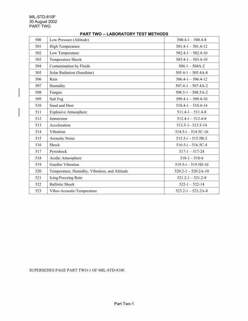
MIL-STD-810F30 August 2002PART TWO
Part Two-1
PART TWO -- LABORATORY TEST METHODS500 Low Pressure (Altitude) 500.4-1 – 500.4-8501 High Temperature 501.4-1 – 501.4-12502 Low Temperature 502.4-1 – 502.4-10503 Temperature Shock 503.4-1 – 503.4-10504 Contamination by Fluids 504-1 – 504A-2505 Solar Radiation (Sunshine) 505.4-1 – 505.4A-8506 Rain 506.4-1 – 506.4-12507 Humidity 507.4-1 – 507.4A-2508 Fungus 508.5-1 – 508.5A-2509 Salt Fog 509.4-1 – 509.4-10510 Sand and Dust 510.4-1 – 510.4-14511 Explosive Atmosphere 511.4-1 – 511.4-8512 Immersion 512.4-1 – 512.4-8513 Acceleration 513.5-1– 513.5-14514 Vibration 514.5-i – 514.5C-16515 Acoustic Noise 515.5-i – 515.5B-2516 Shock 516.5-i – 516.5C-4517 Pyroshock 517-1 – 517-24518 Acidic Atmosphere 518-1 – 518-6519 Gunfire Vibration 519.5-i – 519.5D-10520 Temperature, Humidity, Vibration, and Altitude 520.2-1 – 520.2A-10521 Icing/Freezing Rain 521.2-1 – 521.2-8522 Ballistic Shock 522-1 – 522-14523 Vibro-Acoustic/Temperature 523.2-1 – 523.2A-8
SUPERSEDES PAGE PART TWO-1 OF MIL-STD-810F.
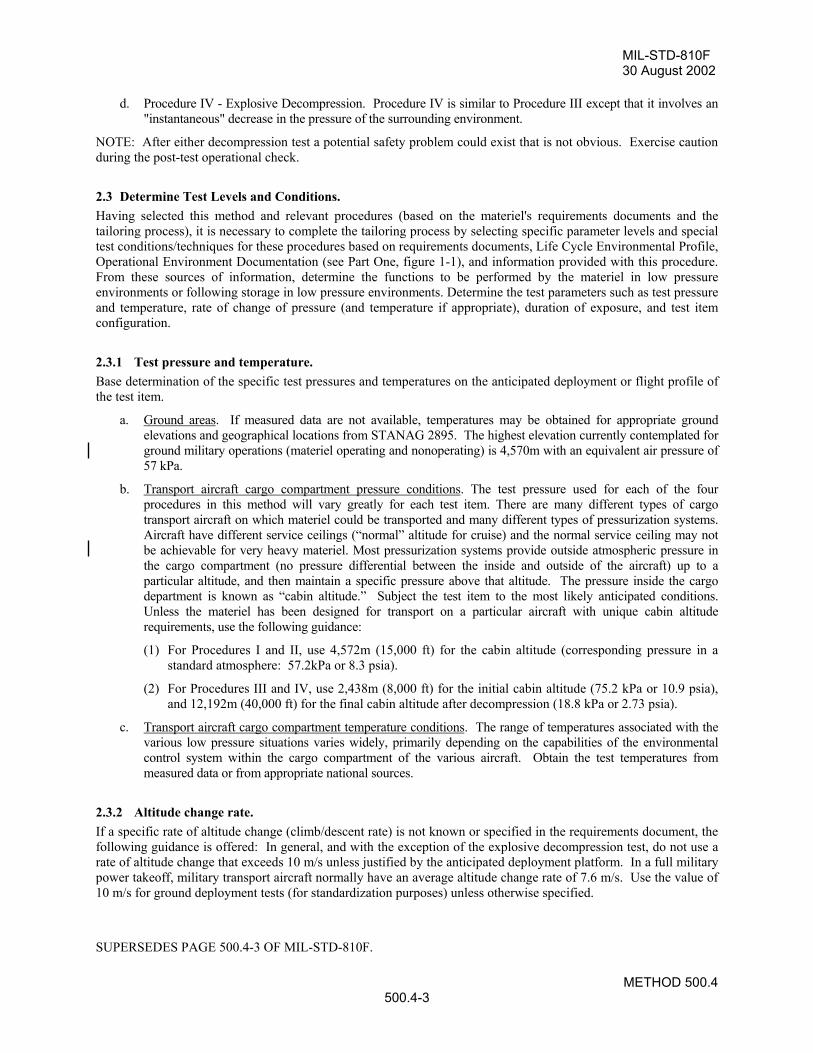
MIL-STD-810F30 August 2002
METHOD 500.4500.4-3
d. Procedure IV - Explosive Decompression. Procedure IV is similar to Procedure III except that it involves an"instantaneous" decrease in the pressure of the surrounding environment.
NOTE: After either decompression test a potential safety problem could exist that is not obvious. Exercise cautionduring the post-test operational check.
2.3 Determine Test Levels and Conditions.Having selected this method and relevant procedures (based on the materiel's requirements documents and thetailoring process), it is necessary to complete the tailoring process by selecting specific parameter levels and specialtest conditions/techniques for these procedures based on requirements documents, Life Cycle Environmental Profile,Operational Environment Documentation (see Part One, figure 1-1), and information provided with this procedure.From these sources of information, determine the functions to be performed by the materiel in low pressureenvironments or following storage in low pressure environments. Determine the test parameters such as test pressureand temperature, rate of change of pressure (and temperature if appropriate), duration of exposure, and test itemconfiguration.
2.3.1 Test pressure and temperature.Base determination of the specific test pressures and temperatures on the anticipated deployment or flight profile ofthe test item.
a. Ground areas. If measured data are not available, temperatures may be obtained for appropriate groundelevations and geographical locations from STANAG 2895. The highest elevation currently contemplated forground military operations (materiel operating and nonoperating) is 4,570m with an equivalent air pressure of57 kPa.
b. Transport aircraft cargo compartment pressure conditions. The test pressure used for each of the fourprocedures in this method will vary greatly for each test item. There are many different types of cargotransport aircraft on which materiel could be transported and many different types of pressurization systems.Aircraft have different service ceilings (“normal” altitude for cruise) and the normal service ceiling may notbe achievable for very heavy materiel. Most pressurization systems provide outside atmospheric pressure inthe cargo compartment (no pressure differential between the inside and outside of the aircraft) up to aparticular altitude, and then maintain a specific pressure above that altitude. The pressure inside the cargodepartment is known as “cabin altitude.” Subject the test item to the most likely anticipated conditions.Unless the materiel has been designed for transport on a particular aircraft with unique cabin altituderequirements, use the following guidance:
(1) For Procedures I and II, use 4,572m (15,000 ft) for the cabin altitude (corresponding pressure in astandard atmosphere: 57.2kPa or 8.3 psia).
(2) For Procedures III and IV, use 2,438m (8,000 ft) for the initial cabin altitude (75.2 kPa or 10.9 psia),and 12,192m (40,000 ft) for the final cabin altitude after decompression (18.8 kPa or 2.73 psia).
c. Transport aircraft cargo compartment temperature conditions. The range of temperatures associated with thevarious low pressure situations varies widely, primarily depending on the capabilities of the environmentalcontrol system within the cargo compartment of the various aircraft. Obtain the test temperatures frommeasured data or from appropriate national sources.
2.3.2 Altitude change rate.If a specific rate of altitude change (climb/descent rate) is not known or specified in the requirements document, thefollowing guidance is offered: In general, and with the exception of the explosive decompression test, do not use arate of altitude change that exceeds 10 m/s unless justified by the anticipated deployment platform. In a full militarypower takeoff, military transport aircraft normally have an average altitude change rate of 7.6 m/s. Use the value of10 m/s for ground deployment tests (for standardization purposes) unless otherwise specified.
SUPERSEDES PAGE 500.4-3 OF MIL-STD-810F.
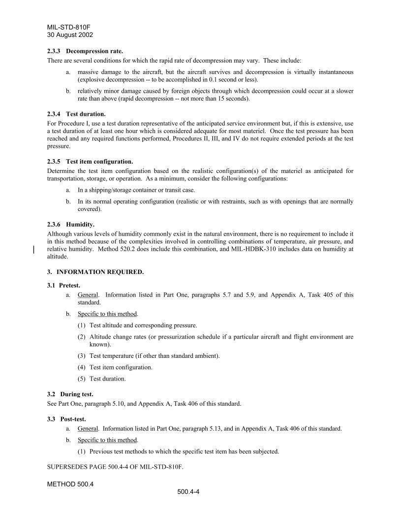
MIL-STD-810F30 August 2002
METHOD 500.4500.4-4
2.3.3 Decompression rate. There are several conditions for which the rapid rate of decompression may vary. These include:
a. massive damage to the aircraft, but the aircraft survives and decompression is virtually instantaneous(explosive decompression -- to be accomplished in 0.1 second or less).
b. relatively minor damage caused by foreign objects through which decompression could occur at a slowerrate than above (rapid decompression -- not more than 15 seconds).
2.3.4 Test duration. For Procedure I, use a test duration representative of the anticipated service environment but, if this is extensive, usea test duration of at least one hour which is considered adequate for most materiel. Once the test pressure has beenreached and any required functions performed, Procedures II, III, and IV do not require extended periods at the testpressure.
2.3.5 Test item configuration. Determine the test item configuration based on the realistic configuration(s) of the materiel as anticipated fortransportation, storage, or operation. As a minimum, consider the following configurations:
a. In a shipping/storage container or transit case.
b. In its normal operating configuration (realistic or with restraints, such as with openings that are normallycovered).
2.3.6 Humidity. Although various levels of humidity commonly exist in the natural environment, there is no requirement to include itin this method because of the complexities involved in controlling combinations of temperature, air pressure, andrelative humidity. Method 520.2 does include this combination, and MIL-HDBK-310 includes data on humidity ataltitude.
3. INFORMATION REQUIRED.
3.1 Pretest. a. General. Information listed in Part One, paragraphs 5.7 and 5.9, and Appendix A, Task 405 of this
standard.
b. Specific to this method.
(1) Test altitude and corresponding pressure.
(2) Altitude change rates (or pressurization schedule if a particular aircraft and flight environment areknown).
(3) Test temperature (if other than standard ambient).
(4) Test item configuration.
(5) Test duration.
3.2 During test. See Part One, paragraph 5.10, and Appendix A, Task 406 of this standard.
3.3 Post-test.a. General. Information listed in Part One, paragraph 5.13, and in Appendix A, Task 406 of this standard.
b. Specific to this method.
(1) Previous test methods to which the specific test item has been subjected.
SUPERSEDES PAGE 500.4-4 OF MIL-STD-810F.
MIL-STD-810F30 August 2002
METHOD 501.4501.4-1
METHOD 501.4
HIGH TEMPERATURE
NOTE: Tailoring is essential. Select methods, procedures, and parameter levels based on the tailoring processdescribed in Part One, paragraph 4.2.2, and Appendix C. Apply the general guidelines for laboratory test methodsdescribed in Part One, paragraph 5 of this standard.
1. SCOPE.
1.1 Purpose. Use high temperature tests to obtain data to help evaluate effects of high temperature conditions on materiel safety,integrity, and performance.
1.2 Application. Use this method to evaluate materiel likely to be deployed in areas where temperatures are higher than standardambient.
1.3 Limitations. Limit use of this method to evaluating the effects of relatively short-term (months, as opposed to years), evendistributions of heat throughout the test item. This method is not generally practical for:
a. Evaluating time-dependent performance degradation (aging) effects that occur during constant long-termexposure to high temperatures (under storage or operational modes) where synergetic effects may beinvolved. For such high temperature aging effects, test in the natural environment.
b. Evaluating materiel in a high temperature environment where solar radiation produces significantthermal gradients in the materiel. For simulating direct solar impingement, use method 505.4,Procedure I.
c. Evaluating actinic (photochemical) effects (use method 505.4, Procedure II).
d. Evaluating the effects of aerodynamic heating.
2. TAILORING GUIDANCE.
2.1 Selecting this Method. After examining requirements documents and applying the tailoring process in Part One of this standard todetermine where high temperatures are foreseen in the life cycle of the test item, use the following to confirm theneed for this method and to place it in sequence with other methods.
2.1.1 Effects of high temperature environments. High temperatures may temporarily or permanently impair performance of materiel by changing physical propertiesor dimensions of the material(s) of which it is composed. The following are examples of problems that could resultfrom high temperature exposure that may relate to the materiel being tested. Consider the following typical problemsto help determine if this method is appropriate for the materiel being tested. This list is not intended to be all-inclusive.
a. Parts bind from differential expansion of dissimilar materials.
b. Lubricants become less viscous; joints lose lubrication by outward flow of lubricants.
c. Materials change in dimension, either totally or selectively.
SUPERSEDES PAGE 501.4-1 OF MIL-STD-810F.
MIL-STD-810F1 January 2000
METHOD 501.4501.4-2
d. Packing, gaskets, seals, bearings and shafts become distorted, bind, and fail causing mechanical orintegrity failures.
e. Gaskets display permanent set.
f. Closure and sealing strips deteriorate.
g. Fixed-resistance resistors change in values.
h. Electronic circuit stability varies with differences in temperature gradients and differential expansion ofdissimilar materials.
i. Transformers and electromechanical components overheat.
j. Operating/release margins of relays and magnetic or thermally activated devices alter.
k. Shortened operating lifetime.
l. Solid pellets or grains separate.
m. High pressures created within sealed cases (projectiles, bombs, etc.).
n. Accelerated burning of explosives or propellants.
o. Expansion of cast explosives within their cases.
p. Explosives melt and exude.
q. Discoloration, cracking or crazing of organic materials.
r. Outgassing of composite materials.
2.1.2 Sequence among other methods.a. General. See Part One, paragraph 5.5.
b. Unique to this method. There are at least two philosophies related to test sequence. One approach is toconserve test item life by applying what are perceived to be the least damaging environments first. Forthis approach, generally apply the high temperature test early in the test sequence. Another approach isto apply environments to maximize the likelihood of disclosing synergetic effects. For this approach,consider high temperature testing following dynamic tests, such as vibration and shock. Although notwritten for such, this test may be used in conjunction with shock and vibration tests to evaluate the effectof dynamic events (i.e., shipping, handling, and shock) on hot materials. Also, this test may contributesignificantly to the results of low pressure testing of seals, e.g., see paragraph 2.1.1d, e and f.
2.2 Selecting Procedures. This method includes two test procedures, Procedure I (Storage) and Procedure II (Operation). Determine theprocedure(s) to be used.
2.2.1 Procedure selection considerations.
When selecting procedures, consider:
a. The operational purpose of the materiel.
b. The natural exposure circumstances.
c. The test data required to determine whether the operational purpose of the materiel has been met.
d. Procedure sequence. If both the storage and operation procedures are to be applied, perform Procedure Ibefore Procedure II.
REPRINTED WITHOUT CHANGE.
MIL-STD-810F1 January 2000
METHOD 501.4501.4-3
e. Other significant heat sources that could affect the materiel such as motors, engines, power supplies, orexhaust air.
2.2.2 Difference between procedures.While both procedures involve temperature conditioning and performance testing, they differ on the basis of thetemperature load prior to and during performance tests. The storage procedure assesses the effects of hightemperature storage on subsequent materiel performance. The operation procedure assesses the effects of hightemperatures during performance.
a. Procedure I - Storage. Use Procedure I to investigate how high temperatures during storage affect themateriel (integrity of materials, and safety/performance of the materiel). This test procedure includesexposing the test item to high temperatures (and low humidity where applicable) that may beencountered in the materiel's storage situation, followed by a performance test at standard or hightemperature ambient conditions.
b. Procedure II - Operation. Use Procedure II to investigate how high ambient temperatures may affectmateriel performance while it is operating. There are two ways to perform Procedure II:
(1) Expose the test item to cyclic chamber conditions with the test item operating either continuously orduring the period of maximum response (highest item temperature).
(2) Expose the test item to a constant temperature and operate the test item when its temperaturestabilizes.
2.3 Determine Test Levels and Conditions.Having selected this method and relevant procedures (based on the test item's requirements documents and thetailoring process), complete the tailoring process by identifying appropriate parameter levels and applicable testconditions and techniques for these procedures. Base these selections on the requirements documents, the Life CycleEnvironmental Profile, Operational Environment Documentation (see Part One, figure 1-1), and informationprovided with this procedure. Consider the following when selecting test levels.
2.3.1 Climatic conditions.Identify the appropriate climatic conditions for the geographic areas in which the materiel will be operated andstored. There are two climatic categories where high temperatures are typically encountered: Hot Dry and BasicHot (Part One, Appendix C, figure C-1). Data for these areas are shown in tables 501.4-I, -II, and -III. Determinehigh temperature levels with respect to:
a. Climatic area of concern.
b. Exposure to solar radiation: Is this exposure directly on the materiel, shipping container, protectivepackage shelter, etc.?
c. Analysis of the path of heat transfer from the ambient air and solar radiation to the materiel.
2.3.2 Exposure conditions.Before determining the levels at which to set test temperatures, determine the way in which the materiel is exposedto heat in normal storage and operational circumstances. Review the LCEP to help make this determination.Consider at least the following exposure conditions:
a. Deployment configuration.
(1) Exposed. Of interest are the most severe conditions that materiel would experience when deployedin any climatic area of the world without the benefit of a protective cover or sheltering enclosure.
(2) Sheltered. Of interest are the most severe conditions that materiel would experience when deployedin any climatic area of the world when under cover or inside a sheltering enclosure. The amount ofventilation available and the presence of adjacent shade can significantly affect the temperature ofthe air surrounding sheltered materiel. Examples of these situations are provided below. (Note: If
REPRINTED WITHOUT CHANGE.
MIL-STD-810F30 August 2002
METHOD 501.4501.4-4
field data are not available, the conditions for this exposure may be approximated using MIL-HDBK-310 or NATO STANAG 2895. The outdoor ambient air temperature and humidity conditionsdescribed in this reference are those measured in standard meteorological shelters at a height of 1.2 to1.8 m (4 to 6 ft) above the ground.)(a) Inside unventilated enclosures.(b) Within enclosed vehicle bodies.(c) Within aircraft sections having surfaces exposed to solar heating.(d) Inside of tents.(e) Under closed tarpaulins.(f) Located above, on, or below the surface of the Earth.
b. Special conditions. Although high temperature testing is generally based on the average temperature ofthe air envelope surrounding the materiel, significant localized heating can occur because of specialheating conditions. This localized heating can be well above the average surrounding air and thereforecan significantly affect the evaluation of the materiel's thermal behavior and performance. When theseconditions exist (as described below), include or simulate them in the high temperature test setup to theextent practical.(1) Aggravated solar. When materiel is located behind glazed or transparent panels or within confined,
unventilated compartments behind thin metallic skins, direct solar impingement may temporarilyraise local air temperatures in excess of those shown in tables 505.4-I and -II. Use caution whenapplying extreme temperatures because of increased damage potential. In these circumstances basetesting on actual field measurements. (Applicable conditions for such testing may indicate usingmethod 505.4 separately or in conjunction with this method.)
(2) Man-made sources. Man-made heat-producing devices (motors, engines, power supplies, high-density electronic packages, etc.) may significantly raise the local air temperature near the materiel,either by radiation, convection, or impingement of exhaust air.
2.3.3 Exposure duration.Determine the duration of exposure that the materiel will experience for each of the exposure conditions identified.Exposure may be constant or cyclic, in which case, also identify the number of times that the exposure occurs.Caution: When testing munitions (including missiles and rockets), ensure the total time at the most severetemperature when temperature-conditioning for dynamic tests, does not exceed the life expectancy of anyexplosive material.
2.3.3.1 Constant temperature exposure.For constant temperature exposure, soak the test item until its temperature has stabilized and maintain the testtemperature at least two hours following stabilization.2.3.3.2 Cyclic temperature exposure.For cyclic exposure, determine the test duration based on an estimate of the number of cycles required to satisfy thedesign requirements and the guidance below. The duration of high temperature exposure may be as significant as thetemperature itself. Because Procedures I and II could expose the test items to cyclic temperatures, the number ofcycles is critical. (Cycles are 24-hour periods unless otherwise specified.)
a. Procedure I - Storage. The number of cycles for the storage test is set at a minimum of seven to coincidewith the one percent frequency of occurrence of the hours of extreme temperatures during the mostsevere month in an average year at the most severe location. (The maximum temperature occurs forapproximately one hour in each cycle.) When considering extended storage, critical materials, ormaterials determined to be very sensitive to high temperature, increase the number of cycles to assure thedesign requirements are met.
b. Procedure II - Operation. The minimum number of cycles for the operational exposure test is three. Thisnumber is normally sufficient for the test item to reach its maximum response temperature. A maximumof seven cycles is suggested when repeated temperature response is difficult to obtain.
NOTE: This maximum response temperature is referenced in several other methods of this standard such asMethod 503.4.
SUPERSEDES PAGE 501.4-4 OF MIL-STD-810F.
MIL-STD-810F1 January 2000
METHOD 501.4501.4-5
2.3.4 Test item configuration.Determine the test item configuration based on realistic configuration(s) of the materiel anticipated for storage andoperation. As a minimum, consider the following configurations:
a. In a shipping/storage container or transit case.
b. Protected or unprotected (under canopy, enclosed, etc.).
c. In its normal operating configuration (realistic or with restraints, such as with openings that are normallycovered).
d. Modified with kits for special applications.
e. Stacked or palletized configurations.
2.3.5 Humidity.Generally, relative humidity (RH) control during high temperature tests is not necessary. In special cases, extremelylow RH may have a significant effect on some materiel during high temperature testing. If the materiel has specialcharacteristics that could be affected by extremely low RH, use the values for RH shown in tables 501.4-I and -II.
2.4 Test Item Operation.When it is necessary to operate the test item, use the following guidelines for establishing test operating procedures.
a. General. See Part One, paragraph 5.8.2.
b. Unique to this method.
(1) Include operating modes that consume the most power (generate the most heat).
(2) Include the required range of input voltage conditions if changes in voltage could affect the test itemthermal dissipation or response (e.g., power generation or fan speed).
(3) Introduce the cooling media that normally would be applied during service use (e.g., forced air orliquid coolant). Consider using cooling medium inlet temperatures and flow rates that represent bothtypical and worst-case degraded temperature and flow conditions.
(4) For steady-state temperature testing, consider thermal stabilization to be achieved when thetemperatures of critical internal operating components are relatively constant. (Because of test itemduty cycling or the operating characteristics, a constant operating temperature may never beachieved.)
(5) For cyclic temperature testing and depending on the cycle and test item characteristics, there may beno thermal stabilization. In this case, the thermal responses of the test item will also be cyclic, i.e.,the peak response temperature is within 2°C of that of the previous cycle.
3. INFORMATION REQUIRED.
3.1 Pretest.The following information is required to conduct high temperature tests adequately.
a. General. Information listed in Part One, paragraphs 5.7 and 5.9, and Appendix A, Task 405 of thisstandard.
b. Specific to this method. Relative humidity control requirements (if necessary). (See paragraph 2.3.5 ofthis method.)
c. Thermocouple locations. The component/assembly/structure to be used for thermal response andtemperature stabilization purposes. (See Part One, paragraph 5.4.)
REPRINTED WITHOUT CHANGE.
MIL-STD-810F30 August 2002
METHOD 501.4501.4-6
3.2 During Test.Collect the following information during conduct of the test:
a. General. Information listed in Part One, paragraph 5.10, and in Appendix A, Task 406 of this standard.
b. Specific to this method.
(1) Record of chamber temperatures (and humidity, if applicable) versus time conditions.
(2) Record of the test item temperature-versus-time data for the duration of the test.
3.3 Post-test.See Part One, paragraph 5.13.
4. TEST PROCESS.
4.1 Test Facility.a. The required apparatus consists of a chamber or cabinet together with auxiliary instrumentation capable
of maintaining and monitoring (see Part One, paragraph 5.18) the required conditions of hightemperature (and humidity, where required) throughout an envelope of air surrounding the test item(s).
b. Unless justified by the materiel platform environment and to prevent unrealistic heat transfer in themateriel, maintain the air velocity in the vicinity of the test item so as to not exceed 1.7 m/s (335 ft/min).
c. Continuously record chamber temperatures and, if required, test item temperatures.
4.2 Controls.a. Temperature. Unless otherwise specified in the test plan, if any action other than test item operation
(such as opening the chamber door) results in a significant change of the test item temperature (morethan 2°C (3.6°F)) or chamber air temperature, re-stabilize the test item at the required temperature beforecontinuing the test. If the operational check is not completed within 15 minutes, reestablish test itemtemperature/RH conditions before continuing.
b. Rate of temperature change. Unless otherwise specified, use a rate of temperature change not exceeding3°C (6°F) per minute to prevent thermal shock.
SUPERSEDES PAGE 501.4-6 OF MIL-STD-810F.
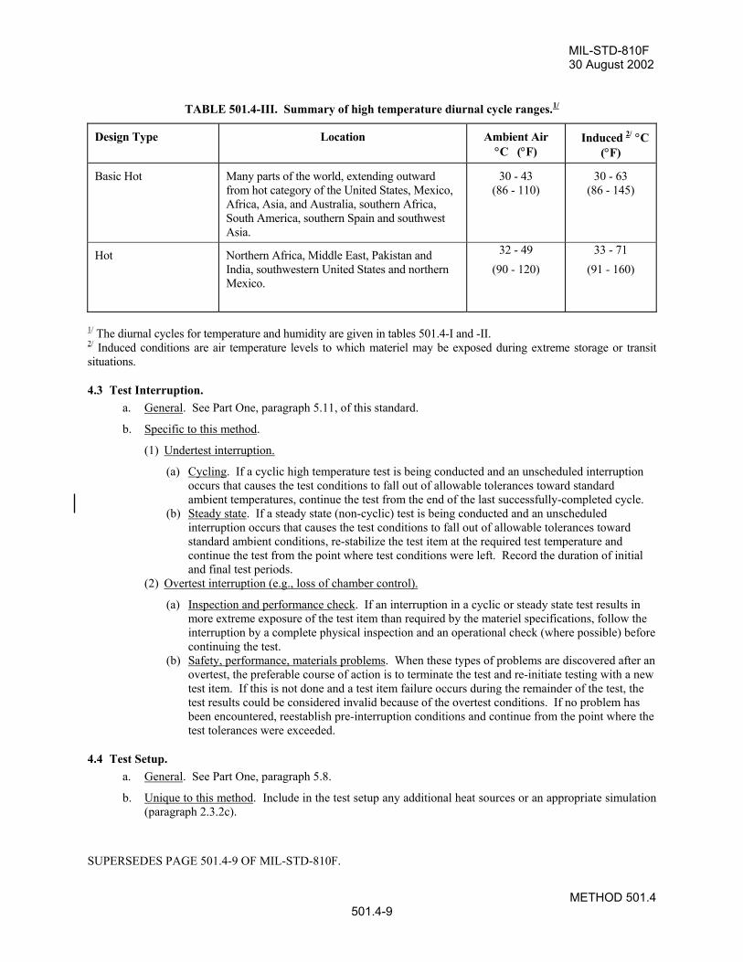
MIL-STD-810F30 August 2002
METHOD 501.4501.4-9
TABLE 501.4-III. Summary of high temperature diurnal cycle ranges.1/
Design Type Location Ambient Air°C (°F)
Induced 2/ °C(°F)
Basic Hot Many parts of the world, extending outwardfrom hot category of the United States, Mexico,Africa, Asia, and Australia, southern Africa,South America, southern Spain and southwestAsia.
30 - 43(86 - 110)
30 - 63(86 - 145)
Hot Northern Africa, Middle East, Pakistan andIndia, southwestern United States and northernMexico.
32 - 49(90 - 120)
33 - 71(91 - 160)
1/ The diurnal cycles for temperature and humidity are given in tables 501.4-I and -II.2/ Induced conditions are air temperature levels to which materiel may be exposed during extreme storage or transitsituations.
4.3 Test Interruption.a. General. See Part One, paragraph 5.11, of this standard.
b. Specific to this method.
(1) Undertest interruption.
(a) Cycling. If a cyclic high temperature test is being conducted and an unscheduled interruptionoccurs that causes the test conditions to fall out of allowable tolerances toward standardambient temperatures, continue the test from the end of the last successfully-completed cycle.
(b) Steady state. If a steady state (non-cyclic) test is being conducted and an unscheduledinterruption occurs that causes the test conditions to fall out of allowable tolerances towardstandard ambient conditions, re-stabilize the test item at the required test temperature andcontinue the test from the point where test conditions were left. Record the duration of initialand final test periods.
(2) Overtest interruption (e.g., loss of chamber control).
(a) Inspection and performance check. If an interruption in a cyclic or steady state test results inmore extreme exposure of the test item than required by the materiel specifications, follow theinterruption by a complete physical inspection and an operational check (where possible) beforecontinuing the test.
(b) Safety, performance, materials problems. When these types of problems are discovered after anovertest, the preferable course of action is to terminate the test and re-initiate testing with a newtest item. If this is not done and a test item failure occurs during the remainder of the test, thetest results could be considered invalid because of the overtest conditions. If no problem hasbeen encountered, reestablish pre-interruption conditions and continue from the point where thetest tolerances were exceeded.
4.4 Test Setup.a. General. See Part One, paragraph 5.8.
b. Unique to this method. Include in the test setup any additional heat sources or an appropriate simulation(paragraph 2.3.2c).
SUPERSEDES PAGE 501.4-9 OF MIL-STD-810F.
MIL-STD-810F30 August 2002
METHOD 501.4501.4-10
4.5 Test Execution.The following steps, alone or in combination, provide the basis for collecting necessary information concerning themateriel in a high temperature environment.
4.5.1 Preparation for test.
4.5.1.1 Preliminary steps.Before starting the test, review pretest information in the test plan to determine test details (e.g., procedures, testitem configuration, cycles, durations, parameter levels for storage/operation, etc.). (See paragraph 3.1, above.)
4.5.1.2 Pretest standard ambient checkout.All test items require a pretest standard ambient checkout to provide baseline data. Conduct the checkout as follows:
Step 1. Install temperature sensors in, on, or around the test item as described in the test plan.Step 2. Install the test item in the chamber (Part One, paragraph 5.8.1) at standard ambient conditions
(Part One, paragraph 5.1).Step 3. Conduct a visual examination of the test item with special attention to stress areas, such as corners
of molded cases, and document the results.Step 4. Conduct an operational checkout (Part One, paragraph 5.8.2) as described in the plan and record
the results.Step 5. If the test item operates satisfactorily, proceed to paragraph 4.5.2 or 4.5.3 as appropriate. If not,
resolve the problems and repeat Step 4 above.
4.5.2 Procedure I - Storage.
Step 1. Place the test item in its storage configuration.Step 2. Adjust the chamber environment to the appropriate test conditions for the start of the test period
and maintain for the specified time following temperature stabilization of the test item.Step 3. a. For cyclic storage, expose the test item to the temperature (and humidity, if applicable)
conditions of the storage cycle for at least seven cycles (if 24-hour cycles are used, this would be atotal of 168 hours) or as specified in the test plan. If noted in the test plan, record the thermalresponse of the test item.b. For constant temperature storage, maintain the test temperature at least two hours following testitem temperature stabilization (see Part One, paragraph 5.4). The additional two hours will helpensure unmeasured internal components actually reach stabilization. If not possible to instrumentinternal components, base any additional soak time on thermal analysis to ensure temperaturestabilization throughout the test item.
Step 4. At the completion of the constant temperature soak or the last cycle, adjust the chamber airtemperature to standard ambient conditions and maintain until the test item temperature isstabilized.
Step 5. Conduct a visual examination and operational checkout of the test item and record the results forcomparison with pretest data.
4.5.3 Procedure II - Operation.
Step 1. With the test item placed in the chamber in its operational configuration, install any additionaltemperature sensors necessary to measure the maximum temperature response of the test item,ensuring the functioning components are included.
Step 2. From the test plan, identify the maximum operational temperature for the materiel, whether it isconstant or cyclic. If constant, go to Step 3; if cyclic, go to Step 8.
Step 3. Steady state temperature exposure. Adjust the chamber air conditions to the required steady statetemperature (and humidity, if applicable) at which the materiel must operate.
SUPERSEDES PAGE 501.4-10 OF MIL-STD-810F.
MIL-STD-810F30 August 2002
METHOD 501.4501.4-11
Step 4. Maintain the chamber conditions at least two hours following test item temperature stabilization(see Part One, paragraph 5.4). If not possible to instrument internal components, base theadditional soak time on thermal analysis to ensure temperature stabilization throughout the testitem.
Step 5. Conduct as thorough a visual examination of the test item as possible considering chamber accesslimitations, and document the results for comparison with pretest data.
Step 6. Operate the test item and allow its temperature to re-stabilize. Conduct an operational checkout ofthe test item in accordance with the test plan and document the results for comparison with pretestdata.
Step 7. Skip Steps 8 through 10 and proceed directly to Step 11.Step 8. Cycling temperature exposure. Adjust the chamber air temperature (and humidity, if applicable) to
the initial conditions of the operational cycle appropriate for materiel deployment and maintainuntil the test item’s temperature has stabilized.
Step 9. Expose the test item to at least three cycles or the number of cycles necessary to assure repeatedtest item response. Conduct as complete a visual examination of the test item as possibleconsidering chamber access limitations. Document the results.
Step 10. Operate the test item during the maximum response period of the exposure cycle. Note that themaximum response period may not coincide with the maximum temperature cycle conditionsbecause of the thermal lag of the test item. Repeat until a complete operational checkout of the testitem has been accomplished in accordance with the approved test plan and the results have beendocumented.
Step 11. With the test item not operating, adjust the chamber air temperature to standard ambientconditions and maintain until the test item temperature has stabilized.
Step 12. Conduct a complete visual examination and operational checkout in accordance with the approvedtest plan and document the results for comparison with pretest data.
5. ANALYSIS OF RESULTS.In addition to the guidance provided in Part One, paragraph 5.14, the following information is provided to assist inthe evaluation of the test results. Apply any data relative to failure of a test item to meet the requirements of themateriel specifications to the test analysis, and consider related information such as:
a. Results of nondestructive examinations (if any) of materiel following the storage test may be conductedat the extreme temperatures.
b. Degradation or changes in operating characteristics allowed at the high extreme temperatures.
c. Necessity for special kits or special operating procedures for high temperature exposure.
d. Evidence of improper lubrication and assurance that the lubricants specified for the environmentalcondition were used.
6. REFERENCE/RELATED DOCUMENTS.a. AR 70-38, Research, Development, Test and Evaluation of Materiel for Extreme Climatic Conditions.
b. MIL-HDBK-310, Global Climatic Data for Developing Military Products.
c. Synopsis of Background Material for MIL-STD-210B, Climatic Extremes for Military Equipment.Bedford, MA: Air Force Cambridge Research Laboratories, 24 January 1974. DTIC numberAD-780-508.
d. NATO STANAG 2895, Extreme Climatic Conditions and Derived Conditions for Use in DefiningDesign/Test Criteria for NATO Forces Materiel.
e. NATO STANAG 4370, Environmental Testing.
f. Allied Environmental Conditions and Test Procedure (AECTP) 300, Climatic Environmental Tests(under STANAG 4370).
SUPERSEDES PAGE 501.4-11 OF MIL-STD-810F.

MIL-STD-810F1 January 2000
METHOD 501.4501.4-12
THIS PAGE INTENTIONALLY BLANK
REPRINTED WITHOUT CHANGE.
MIL-STD-810F30 August 2002
METHOD 502.4502.4-7
Step 2. Conduct as complete a visual examination of the test item as chamber access limitations willallow.
Step 3. Document the results.Step 4. Conduct an operational checkout of the test item as in paragraph 4.5.1.2, Step 6.Step 5. Document the results.Step 6. If manipulation of the test item is required at low temperature, proceed to Step 4 of paragraph
4.5.4. If not, proceed to step 7 of this procedure.Step 7. Adjust the chamber air temperature to standard ambient and maintain until temperature
stabilization of the test item has been achieved.Step 8. Conduct a complete visual examination of the test item.Step 9. Document the results.Step 10. If appropriate, conduct an operational checkout and record results for comparison with data
obtained in paragraph 4.5.1.2, Step 6.
4.5.4 Procedure III - Manipulation.Step 1. With the test item in the test chamber, adjust the chamber air temperature to the low operating
temperature of the test item as determined from the test plan. Maintain for two hours followingtemperature stabilization of the test item.
Step 2. While maintaining the low operating temperature, place the test item in its normal operatingconfiguration by using the options of Step 4.
Step 3. Reestablish the temperature to that used in Step 1, above.Step 4. Based on the type of test chamber available, select one of the two following options:
Option 1 - To be used when a "walk-in" type chamber is available: With personnel clothed andequipped as they would be in a low temperature tactical situation, disassemble the testitem as would be done in the field, and repack it in its normal shipping/storagecontainer(s), transit case, or other mode and configuration.
Option 2 - To be used when small chambers (non-walk-in) are used: Perform the option 1procedure, except the disassembly and packing will be performed by personnelreaching through chamber access holes or the open door while they are wearing heavygloves such as would be required in the natural environment. NOTE - Opening of thechamber door may cause frost to form on the test item in addition to a gradualwarming of the test item. Limit manipulation necessary to perform the required setupor teardown to 15-minute intervals, between which reestablish the temperature of step1 above.
Step 5. If operation of the test item is required at low temperatures, repeat step 2, above, and thenproceed to Step 1 of paragraph 4.5.3. If not, proceed to step 6 of this procedure.
Step 6. Conduct a complete visual examination of the test item.Step 7. Document the results for comparison with the pretest data.Step 8. Adjust the chamber air temperature to standard ambient and maintain until the test item has
reached temperature stabilization.Step 9. Conduct a complete visual examination of the test item.Step 10. Document the results.Step 11. If appropriate, conduct an operational checkout of the test item and record results for comparison
with data obtained in paragraph 4.5.1.2, Step 6.
5. ANALYSIS OF RESULTS.In addition to the guidance provided in Part One, paragraph 5.14, the following information is provided to assist inthe evaluation of the test results. Apply any data relative to failure of a test item to meet the requirements of themateriel specifications to the test analysis, and consider related information such as:
a. Nondestructive test/examination following exposure to low temperature may be conducted at the lowtest temperature.
b. Degradation allowed in operating characteristics when at low temperatures.
c. Necessity for special kits or special cold weather procedures.
SUPERSEDES PAGE 502.4-7 OF MIL-STD-810F.
MIL-STD-810F1 January 2000
METHOD 502.4502.4-8
d. Evidence of improper lubrication and assurance that lubricants specified for the environmental conditionwere used.
e. For starting failure on internal combustion engines, assurance of the presence of proper fuels anddeicers, if appropriate.
f. Condition and adequacy of the power source.
6. REFERENCE/RELATED DOCUMENTS.a. AR 70-38, Research, Development, Test and Evaluation of Materiel for Extreme Climatic Conditions.
b. MIL-HDBK-310, Global Climatic Data for Developing Military Products.
c. Synopses of Background Material for MIL-STD-210B, Climatic Extreme for Military Equipment.Bedford, MA: Air Force Cambridge Research Laboratories, January 1974. DTIC number AD-780-508.
d. NATO STANAG 2895, Extreme Climatic-Conditions and Derived Conditions for Use in DefiningDesign/Test Criteria for NATO-Forces Materiel.
e. STANAG 4370, Environmental Testing.
f. Allied Environmental Conditions and Test Publication 300, Climatic Environmental Tests (underSTANAG 4370).
REPRINTED WITHOUT CHANGE.
MIL-STD-810F30 August 2002
METHOD 503.4503.4-1
METHOD 503.4
TEMPERATURE SHOCK
NOTE: Tailoring is essential. Select methods, procedures, and parameter levels based on the tailoring processdescribed in Part One, paragraph 4.2.2, and Appendix C. Apply the general guidelines for laboratory test methodsdescribed in Part One, paragraph 5 of this standard.
1. SCOPE.
1.1 Purpose. Use temperature shock tests to determine if materiel can withstand sudden changes in the temperature of thesurrounding atmosphere without experiencing physical damage or deterioration in performance. For the purpose ofthis document, "sudden changes" is defined as, "greater than 10°C per minute."
1.2 Application.
1.2.1 Normal environment. Use this method when the requirements documents specify the materiel is likely to be deployed where suddensignificant changes of air temperature may be experienced. This method is intended to only evaluate the effects ofsudden temperature changes of the outer surfaces of materiel, items mounted on the outer surfaces, or internal itemssituated near the external surfaces. Typically, this addresses:
a. The transfer of materiel between heated areas and low temperature environments.
b. Ascent from a high temperature ground environment to high altitude via a high performance vehicle (hotto cold only).
c. Air delivery/air drop at high altitude/low temperature from aircraft enclosures when only the externalmaterial (packaging or materiel surface) is to be tested.
1.2.2 Safety and screening. Except as noted in paragraph 1.3, use this method to reveal safety problems and potential flaws in materiel normallyexposed to less extreme rates of temperature change (as long as the test conditions do not exceed the designlimitations of the materiel). Although not intended to be used for environmental stress screening (ESS), with properengineering this method can also be used as a screening test (using more extreme temperature shocks) to revealpotential flaws in materiel exposed to less extreme temperature change conditions.
1.3 Limitations. This method is not intended for materiel that will not experience sudden extreme temperature changes because of itspackaging, installed location, etc. This method does not replace the assessment of performance characteristics afterlengthy exposure to extreme temperatures, such as with methods 501.4 and 502.4. Additionally, this method doesnot address the temperature shock experienced by materiel transferred between air and liquid or two liquids, thethermal shock caused by rapid transient warmup by engine compressor bleed air, or aerodynamic loading. Exceptfor ESS, this method is inappropriate if the actual transfer time in a service environment will not produce asignificant thermal shock. Additionally, this method does not address materiel that has been exposed to heat from afire and subsequently cooled with water.
SUPERSEDES PAGE 503.4-1 OF MIL-STD-810F.
MIL-STD-810F1 January 2000
METHOD 503.4503.4-2
2. TAILORING GUIDANCE.
2.1 Selecting this Method. After examining requirements documents and applying the tailoring process in Part One of this standard todetermine where thermal shocks are foreseen in the life cycle of the materiel, use the following to confirm the needfor this method and to place it in sequence with other methods.
2.1.1 Effects of thermal shock environments. Effects of thermal shocks are usually more severe near the outer portions of materiel. The further from the surface(depending, of course, on the properties of the material involved), the slower and less significant the thermalchanges. Transit cases, packaging, etc. will lessen the effects of thermal shock on the enclosed materiel even more.Sudden temperature changes may either temporarily or permanently affect operation of materiel. The following areexamples of problems that could result from thermal shock exposure that may relate to the materiel being tested.Consider the following typical problems to help determine if this method is appropriate for the materiel being tested.This list is not intended to be all-inclusive.
a. Physical.
(1) Shattering of glass vials and optical materiel.
(2) Binding or slackening of moving parts.
(3) Cracking of solid pellets or grains in explosives.
(4) Differential contraction or expansion rates or induced strain rates of dissimilar materials.
(5) Deformation or fracture of components.
(6) Cracking of surface coatings.
(7) Leaking of sealed compartments.
(8) Failure of insulation protection.
b. Chemical.
(1) Separation of constituents.
(2) Failure of chemical agent protection.
c. Electrical.
(1) Changes in electrical and electronic components.
(2) Electronic or mechanical failures due to rapid water or frost formation.
(3) Excessive static electricity.
2.1.2 Sequence among other methods.a. General. See Part One, paragraph 5.5.
b. Unique to this method. Use test item response characteristics and performance determinationinformation obtained from the high and low temperature tests to better define the test conditions to beused for this procedure.
2.2 Selecting Procedures. This method includes two test procedures, Procedure I (Steady State) and Procedure II (Cyclic). Determine theprocedure(s) to be used.
REPRINTED WITHOUT CHANGE.
MIL-STD-810F1 January 2000
METHOD 503.4503.4-3
2.2.1 Procedure selection considerations. When selecting procedures, consider:
a. The expected exposure temperatures in service.
b. The materiel's logistic or deployment configuration.
c. Environmental stress screening (ESS) requirements.
2.2.2 Difference between procedures. While both procedures involve temperature conditioning and performance testing, they differ on the basis oftemperature stabilization prior to shocks.
a. Procedure I - Steady State. Procedure I employs constant temperature at each of the extreme shockconditions because, in many instances, the thermal shock itself so outweighs the other thermal effectsthat the test may be performed using two constant temperatures. This is particularly the case when moresevere shocks are desired, such as for evaluation of safety or initial design, and when extreme values willbe used.
b. Procedure II - Cyclic. When a careful simulation of a real environment is required, use Procedure IIbecause the upper temperature follows part of an appropriate diurnal cycle. From the requirementsdocuments determine the function (operational requirement) to be achieved by the materiel and adefinition of the circumstances responsible for the thermal shock.
2.3 Determine Test Levels and Conditions. Having selected this method and relevant procedures (based on the test item's requirements documents and thetailoring process), complete the tailoring process by identifying appropriate parameter levels and applicable testconditions and techniques for these procedures. Base these selections on the requirements documents, the Life CycleEnvironmental Profile, Operational Environment Documentation (see Part One, figure 1-1), stress screeningrequirements and information provided with this procedure. Consider tailoring known service extreme temperaturesif the intent of the test is to reproduce induced strain rates found in service. Use values other than those suggested ifrealistic. Consider the following when selecting test levels. This method addresses several exposure situations:aircraft flight exposure, air delivery - desert, and ground transfer or air delivery - arctic. Based on the anticipateddeployment, determine which test variation is applicable. The extreme exposure range should determine the testconditions, but extend the test levels as necessary to detect design flaws.
a. Aircraft flight exposure. This is appropriate if the materiel is to be exposed to desert or tropical groundheat and possible direct solar heating and, a few minutes later, exposed to the extreme low temperaturesassociated with high altitude.
b. Air delivery - desert. This is appropriate for materiel which is delivered over desert terrain fromunheated, high-altitude aircraft, but use the ambient air temperature (no solar loading).
c. Ground transfer or air delivery - arctic. This is intended to test materiel for the effects of movement toand from heated storage, maintenance, or other enclosures or a heated cargo compartment in coldregions.
d. Engineering design. This is used to detect marginal design issues.e. ESS. ESS is used for evaluating workmanship practices.
2.3.1 Climatic conditions.
Identify the appropriate climatic conditions for the geographic areas in which the materiel will be operated andstored. Actual response temperatures achieved when materiel is exposed to the climatic conditions of the variousground climatic categories could be obtained from the test results of high and low temperature exposure (methods501.4, 502.4, and 505.4) for either the operational or storage configuration. The latter assumption must take intoaccount the induced effects of solar radiation during storage and transit in various climates.
REPRINTED WITHOUT CHANGE.
MIL-STD-810F30 August 2002
METHOD 503.4503.4-4
2.3.2 Exposure conditions. Select the test temperatures from field data or from the requirements documents, if available. If not available,determine the test temperatures from the anticipated deployment application or world areas in which the materielwill be deployed, or from the most extreme nonoperating temperature requirements. Except for stress screeningpurposes, recommend using a range of temperatures that reflects that anticipated in service rather than somearbitrary extreme range.
a. Deployment application (aircraft flight exposure). The thermal stresses and rates that materiel willexperience during exposure to the air flight operational environment are dependent upon the ambientconditions, flight conditions, and performance of the onboard environmental control systems. Thetemperature and humidity at various altitudes can be found in MIL-HDBK-310.
b. Air delivery/air drop. The test conditions for this exposure are based upon the probable conditions in thecargo compartment of the aircraft (or other transport location) and on the ground at the point of impact.Use a lower temperature extreme that assumes an unheated, unpressurized aircraft cargo compartmentwith the aircraft at an altitude of 8 kilometers (26,200 ft). This is the limiting altitude for cargo aircraftbecause of oxygen-pressure requirements when the aircraft cargo compartment is unpressurizedimmediately before air drop operations. The temperature at this altitude can be found inMIL-HDBK-310. Determine the high temperature surface extremes from the appropriate tables inMethod 501.4. NOTE: Materiel packaging will normally mitigate thermal shocks. The air delivery/air drop scenario may not involve significant thermal shock to the materiel itself.
c. Ground transfer/air delivery - arctic. The conditions developed for heated enclosures located in coldregions are 21°C (70°F) and 25 percent relative humidity. These conditions roughly correspond tonormal heating practices in the Arctic and on aircraft. Base selection of the outside ambient conditionsupon the climatic categories or areas listed in the appropriate table in Method 502.4.
d. Engineering design. Use test conditions that reflect the extreme anticipated storage conditions.
2.3.3 Test duration (number of shocks). For materiel that is likely to be exposed only rarely to thermal shock, perform one shock for each appropriatecondition. There is little available data to substantiate a specific number of shocks when more frequent exposure isexpected. In lieu of better information, apply three shocks or more at each condition, the number dependingprimarily on the anticipated service events. The objective of this test is to determine the effect of rapid temperaturechanges on the materiel. Therefore, expose the test item to the temperature extremes for a duration equal to eitherthe actual operation, or to that required to achieve temperature stabilization.
2.3.4 Extreme high temperature exposure. Materiel is likely to experience the highest heating during storage in the sun in the Hot Dry and Basic Hot climaticregions. Therefore, conduct transitions from hot to cold with the test item stabilized at its high storage temperature.Conduct transitions from cold to hot with the high temperature facility’s air temperature at the maximum storagetemperature of the appropriate cycle. Immediately following the cold-to-hot transfer, cycle the high temperaturefacility through the appropriate diurnal cycle (Method 501.4) from the beginning of the hour at which the maximumair temperature is experienced until the test item maximum operational response temperature is reached (seeMethod 501.4, paragraph 2.3.3b). Other tests, such as stress screening, may require even more extremetemperatures.
2.3.5 Test item configuration.
The configuration of the test item strongly affects test results. Therefore, use the anticipated configuration of theitem during storage, shipment, or use. As a minimum, consider the following configurations:
a. In a shipping/storage container or transit case, and installation of a thermally conditioned item into acontainer conditioned at another temperature.
b. Protected or unprotected.c. Deployed (realistically or with restraints).
SUPERSEDES PAGE 503.4-4 OF MIL-STD-810F.
MIL-STD-810F1 January 2000
METHOD 503.4503.4-5
d. Modified with kits for special applications.
e. Packaged for airdrop.
2.3.6 Temperature stabilization. Stabilize the test item temperature (prior to transfer) for as long as necessary to ensure a uniform temperaturethroughout at least the outer portions of the test item.
2.3.7 Relative humidity. For most test programs, the relative humidity (RH) is not controlled. During the thermal shock test it may, however,have a significant effect on some materiel, e.g., cellulosic materials which are typically porous, into which moisturecan migrate and then expand upon freezing. Do not attempt to control relative humidity unless specifically required.
2.3.8 Transfer time. Ensure the transfer time reflects the time associated with the actual thermal shock in the life cycle profile. It shouldbe as rapid as possible, but if the transfer takes more than one minute, justify the extra time.
2.4 Special Considerations. The test conditions as presented in this procedure are intended to be in general agreement with other extremesdescribed in this document. The primary purpose in establishing these levels is to provide realistic conditions for thetraverse between the two temperature extremes. Therefore, before transfer, stabilize the test item at the mostrealistic temperature that would be encountered during the specific operation, or possibly the most extreme test itemstabilization temperature, if appropriate. Consider tailoring known service extreme temperatures, if the intent of thetest is to reproduce induced strain rates found in service.
3. INFORMATION REQUIRED.
3.1 Pretest. The following information is required to conduct temperature shock tests adequately.
a. General. Information listed in Part One, paragraphs 5.7 and 5.9, and Appendix A, Task 405 of thisstandard.
b. Specific to this method.
(1) Test item configuration.
(2) Test temperature extremes or test item thermal rates of change.
(3) Duration of exposure at each temperature.
(4) Test item response temperature (from method 501.4).
(5) For Procedure II, the high temperature cycle, and the initial temperature for the temperature cycling.
(6) The component/assembly/structure to be used for thermal response and temperature stabilizationpurposes (if required). (See Part One, paragraph 5.4.)
3.2 During Test.For test validation purposes, record deviations from planned or pre-test procedures or parameter levels, includingany procedural anomalies that may occur.
3.3 Post-test.
Record the following post-test information.
a. General. Information listed in Part One, paragraph 5.13, and in Appendix A, Task 406 of this standard.
REPRINTED WITHOUT CHANGE.
MIL-STD-810F30 August 2002
METHOD 503.4503.4-6
b. Specific to this method.
(1) Previous test methods to which the specific test item has been exposed.
(2) Duration of each exposure.
(3) Status of the test item for each visual examination.
(4) Test temperatures.
(5) Results of operational checks.
(6) Transfer times (e.g., "door open" to "door closed").
4. TEST PROCESS.
4.1 Test Facility.
4.1.1 Apparatus. The required apparatus consists of two chambers or cabinets, or a two-celled chamber in which the test conditionscan be established and maintained. Unless otherwise specified, use chambers equipped so that, after transfer of thetest item, the test conditions within the chamber can be stabilized within five minutes. Use materiel handlingequipment, if necessary, for transfer of the test item between chambers.
4.1.2 Instrumentation. Use chambers equipped with auxiliary instrumentation capable of monitoring (see Part One, paragraph 5.18) the testconditions throughout an envelope of air surrounding the test item(s). (See Part One, paragraph 5.3.) Quick-disconnect thermocouples may be necessary for monitoring test item conditions following changes.
4.2 Controls.
4.2.1 Temperature. Unless otherwise specified in the test plan, if any action other than test item operation (such as opening of thechamber door, except at transfer time) results in a significant change (more than 2°C (3.6°F)) of the test itemtemperature or chamber air temperature, stabilize the test item at the required temperature before continuation.
4.2.2 Air velocity. Unless justified by the materiel's platform environment, and to provide standard testing conditions, use an airvelocity that does not exceed 1.7 m/s (335 ft/min) in the vicinity of the test item.
4.3 Test Interruption.
a. General. See Part One, paragraph 5.11 of this standard.
b. Specific to this method.
(1) Undertest interruption. If, before the temperature change, an unscheduled test interruption occursthat causes the test conditions to exceed allowable tolerances toward standard ambient temperatures,reinitiate the test at the point of interruption and reestablish the test item at the test condition. If the
SUPERSEDES PAGE 503.4-6 OF MIL-STD-810F.
MIL-STD-810F1 January 2000
METHOD 503.4503.4-7
interruption occurs during the transfer, reestablish the test item at the previous temperature and thentransfer.
(2) Overtest interruption. Follow any interruption that results in more extreme exposure of the testitem than required by the materiel specification by a complete physical examination and operationalcheck of the test item (where possible) before any continuation of testing. This is especially truewhere a safety problem could exist, such as with munitions. If a problem is discovered, thepreferable course of action is to stop the test and start over with a new test item. If this is not doneand test item failure occurs during the remainder of the test, the test results could be invalid due tothe overtest condition. If no problem is discovered, reestablish pre-interruption conditions andcontinue from the point where the test tolerances were exceeded.
4.4 Test Execution.The following steps, alone or in combination, provide the basis for collecting necessary information concerning themateriel's susceptibility to temperature shock.
4.4.1 Preparation for test.
4.4.1.1 Preliminary steps. Before starting the test, review pretest information in the test plan to determine test details (e.g., procedures, testitem configuration, temperature levels, cycles, temperature stabilization determination, durations, etc.). (Seeparagraph 3.1 above.)
4.4.1.2 Pretest standard ambient checkout. All test items require a pretest standard ambient checkout to provide baseline data. Examine munitions and otherappropriate materiel by nondestructive examination methods. Conduct the checkout as follows:
Step 1. Stabilize the test item at standard ambient conditions (Part One, paragraph 5.1).
Step 2. Conduct a complete visual examination of the test item (evaluate against paragraph 2.1.1) withspecial attention to stress areas such as corners of molded areas and interfaces between differentmaterials (e.g., component lead/ceramic interfaces of visible electronic parts), and document theresults for comparison with post test data.
Step 3. Conduct an operational checkout in accordance with the approved test plan and record the results.
Step 4. If the test item operates satisfactorily, proceed to the next Step. If not, resolve the problems andrestart at Step 1, above.
Step 5. Prepare the test item in accordance with Part One, paragraph 5.8 and in the required test itemconfiguration.
4.4.2 Procedures. The following procedures provide the basis for collecting the necessary information concerning the materiel in asevere temperature shock environment. The procedures depicted on figures 1 and 2 arbitrarily begin with the lowertemperature, but could be reversed to begin with the higher temperature if it is more realistic. Specific points onfigures 1 and 2 (in parentheses) are referenced in the following text.
30 August 2002
METHOD 503.4503.4-8
4.4.2.1 Procedure I - Shock from constant extreme temperatures. (Figure 503.4-1.)Step 1. With the test item in the chamber, adjust the chamber air temperature to the low temperature
extreme specified in the test plan (a). Maintain this temperature for a period as determined in thetest plan (a-b).
Step 2. Transfer the test item in no more than one minute (b-c) to an atmosphere at temperature T2 thatwill produce the thermal shock specified in the test plan, and maintain this temperature asspecified in the test plan (c-e).
Step 3. If required in the test plan, evaluate the effects of the thermal shock on the test item to the extentpractical.
Step 4. If other cycles in reversed directions are required, transfer the test item to the T1 environment inless than one minute (e-f) and stabilize as required in the test plan (f-b), evaluate the thermal shockeffects (if required), and continue as in steps 2 and 3 above. If other one way shocks are required,return the test item to the T1 environment at a rate of not more than 3°C/minute and repeat Steps1-3. If no other shocks are required, go to Step 5.
Step 5. Return the test item to standard ambient conditions. Step 6. Examine the test item and, if appropriate, operate. Record the results for comparison with pretest
data.
4.4.2.2 Procedure II - Shock to/from cyclic high temperatures. (Figure 503.4-2.)Step 1. With the test item in the chamber, adjust the chamber air temperature to the low temperature
extreme specified in the test plan (a) at a rate not to exceed 3°C/min. Maintain this temperature fora period as determined in the test plan (a-b).
Step 2. Transfer the test item to the maximum air temperature of the high temperature cycle (c) (asspecified in the test plan) in no more than one minute. As soon as the chamber door is closed andthe chamber recovers to the peak temperature, cycle the chamber through part of the appropriatediurnal cycle until the chamber air temperature reaches the test item response temperature (d)(obtained from Method 501.4, paragraph 2.3.3b). Maintain this temperature as specified in the testplan (d-e).
Step 3. If no other cycles are required, return the test item to standard ambient conditions and proceed toStep 7.
Step 4. Transfer the test item to the lower temperature environment (f) in no more than one minute andstabilize as required in the test plan (f-h). If other cycles are required, proceed to Step 6.
Step 5. If no other cycles are required, return the test item to standard ambient conditions, and proceed toStep 7. NOTE: Unless the requirements documents indicate otherwise, if the test procedure is interruptedbecause of work schedules, etc., maintaining the test item at the test temperature for the timerequired will facilitate completion of the test when resumed. If the temperature is changed, beforecontinuing the test, restabilize the test item at the temperature of the last successfully completedperiod before the interruption.
Step 6. Repeat steps 2, 3, and 4 as specified in the test plan. Step 7. Examine the test item and, if appropriate, operate. Record the results for comparison with pretest
data.
5. ANALYSIS OF RESULTS. Follow the guidance provided in Part One, paragraph 5.14, to assist in the evaluation of the test results. Analyze anyfailure of a test item to meet the requirements of the materiel specifications.
SUPERSEDES PAGE 503.4-8 OF MIL-STD-810F.
MIL-STD-810F1 January 2000
METHOD 504504-1
METHOD 504
CONTAMINATION BY FLUIDSNOTE: Tailoring is essential. Select methods, procedures, and parameter levels based on the tailoring processdescribed in Part One, Paragraph 4.2.2, and Appendix C. Apply the general guidelines for laboratory test methodsdescribed in Part One, paragraph 5 of this standard.
1. SCOPE.
1.1 Purpose.Use contamination by fluids tests to determine if materiel is unacceptably affected by temporary exposure tocontaminating fluids (liquids) such as may be encountered during its life cycle, either occasionally1/, intermittently2/,or over extended periods3/.
1.2 Application.Select the tests described in this method when there is a high probability of fluid contamination during the life cycleof the materiel. Contamination may arise from exposure to fuels, hydraulic fluids, lubricating oils, solvents, andcleaning fluids, de-icing and anti-freeze fluids, runway de-icers, insecticides, disinfectants, coolant dielectric fluid,and fire extinguishants.
WARNING: THIS METHOD REQUIRES THE USE OF SUBSTANCES AND/OR TEST PROCEDURES THATMAY HAVE AN ENVIRONMENTAL IMPACT OR BE INJURIOUS TO HEALTH, IF ADEQUATEPRECAUTIONS ARE NOT TAKEN. ADDITIONAL INFORMATION IS PROVIDED IN ANNEX A. REFERTO THE SUPPLIER'S MATERIAL SAFETY DATA SHEET (MSDS) OR EQUIVALENT FOR CHEMICALCOMPATABILITY AND HEALTH HAZARD DATA ON THE VARIOUS CHEMICALS USED, ANDCOORDINATE WITH LOCAL ENVIRONMENTAL AUTHORITIES. ENSURE ALL POST-TEST MATERIALSARE DISPOSED OF IN ACCORDANCE WITH LOCAL, STATE AND FEDERAL REGULATIONS.
1.3 Limitations.This test is not intended to demonstrate the suitability of materiel to perform during continuous contact with a fluid,e.g., an immersed fuel pump, nor should it be used to demonstrate resistance to electrolytic corrosion.
2. TAILORING GUIDANCE.
2.1 Selecting the Contamination by Fluids Method.After examining requirements documents and applying the tailoring process in Part One of this standard todetermine where exposure to contaminating fluids is foreseen in the life cycle of the test item, use the following toconfirm the need for this method and to place it in sequence with other methods. For specifically testing small armssystems, consider using Test Operations Procedure (TOP) 3-2-609.
2.1.1 Effects of the contaminating fluids environment.During its life cycle, materiel may be accidentally or intentionally exposed to one or more fluids that could have anadverse effect on the materiel. As a result, exposure of materiel to contaminating fluids may either temporarily orpermanently impair the operation of the materiel by changing the physical properties of the material(s) composing it.Consider the following typical examples of problems to help determine if this method is appropriate for the materielbeing tested. The list is not intended to be all-inclusive and some of the examples may overlap.
a. Packaging failure.
b. Crazing or swelling of plastics and rubbers.
1/ Extraordinary/unusual circumstances occurring once or twice a year.2/ Regular basis under normal operation; possibly seasonally over the life of the materiel.3/ Long periods such that materiel is thoroughly exposed.
REPRINTED WITHOUT CHANGE.
MIL-STD-810F30 August 2002
METHOD 504504-2
c. Leeching of antioxidants and other soluble materials.
d. Seal or gasket failures.
e. Adhesion failures.
f. Paint/legend removal.
g. Corrosion.
h. Melting or decomposition.
2.1.2 Sequence among other methods.
a. General. See Part One, paragraph 5.5.
b. Unique to this method. Do not perform these tests prior to other climatic environmental tests because ofpotential effect of the contaminants or their removal by decontaminants.
2.2 Selecting Procedure Variations.This method has one procedure. Possible variations are described below. The most significant parameters used inthis test method are the fluid to be used, the temperature, and duration of exposure. It is also important in this testprocedure to specify the operational configuration of the test item, as well as whether or not the test item is heatdissipating during operation.
2.2.1 Length of exposure.There are three options provided in the test procedure: occasional contamination, intermittent contamination, andextended contamination (paragraph 1.1). From the requirements document, determine the option to be used basedon the anticipated life cycle scenario, along with the order of application of the test fluids if more than one isrequired.
2.2.2 Contaminant fluid groups. (See paragraph 2.2.3 below.)
The following groups of fluids are listed in table 504-I.
2.2.2.1 Fuels.Fuels will, for the most part, be of the gasoline or kerosene type, and whereas the former may be expected toevaporate rapidly - possibly with few permanently harmful effects, the latter - being more persistent - can bedamaging to many elastomers, particularly at elevated temperatures. Paints and most plastics are normally notaffected by fuels, but silicone resin bonded boards may tend to de-laminate after prolonged exposure. Some fuelsmay have additives to inhibit icing or to dissipate static charges. Where there is reason to believe that theseadditives may increase the severity of the test, include them in the test fluids.
2.2.2.2 Hydraulic fluids.Commonly used hydraulic fluids may be of the mineral oil or ester-based synthetic type. The latter are damaging tomost elastomers and to plastics; phosphate esters are especially damaging to these materials and to paint finishes.
2.2.2.3 Lubricating oils.Mineral or synthetic-based lubricating oils may be at elevated temperatures in their working states. Mineral oil isdamaging to natural rubber but less so to synthetics such as polychloroprene, chloro-sulphonated polyethylene, andsilicone rubber. Synthetic lubricants are extremely damaging to plastics such as PVC as well as to many elastomers.
2.2.2.4 Solvents and cleaning fluids.Many areas of aircraft or vehicles may require dirt or grease removal before servicing can begin. The fluids given intable 504-I are representative of those presently in use.
SUPERSEDES PAGE 504-2 OF MIL-STD-810F.
MIL-STD-810F30 August 2002
METHOD 504504-5
(1) Record of chamber temperature versus time conditions.
(2) Test fluid(s) and the corresponding temperature.
(3) Any deterioration noted during visual checks.
3.3 Post Test.The following post test information is required.
a. General. Information listed in Part One, paragraph 5.13, and in Appendix A, Task 406 of this standard.
b. Specific to this method.
(1) Results of each functional check after each exposure to each of the specified fluids.
(2) Any degradation of materials, protective finishes, etc. (see paragraph 3.1b(8)).
(3) Immersion times and exposure type.
4. TEST PROCESS.
4.1 Test Facility.Use a test facility that includes an enclosure and a temperature control mechanism designed to maintain the test itemat a specified temperature, as well as a means of monitoring the prescribed conditions (see Part One, paragraph5.18). The contamination facility is a tank within the test enclosure (non-reactive with the contaminant) in whichthe test item is exposed to the selected contaminant by immersion, spraying, splashing, or brushing. Design thetemperature control mechanism to maintain the test item at the specified temperature. When the flash point of thetest fluid is lower than the test temperature, design the test facility in accordance with fire and explosion standards.
4.2 Controls.Ensure the test and cleaning (decontaminating) fluids are handled and disposed of as required by localenvironmental and safety requirements. Some test fluid specifications are referenced in table 504-I.
4.3 Test Interruption.
a. General. See Part One, paragraph 5.11, of this standard.
b. Specific to this method.
(1) Undertest interruption. If an unscheduled test interruption occurs that causes the test conditions toexceed allowable tolerances toward standard ambient conditions, give the test item a completevisual examination and develop a technical evaluation of the impact of the interruption on the testresults. Restart the test at the point of interruption and restabilize the test item at the test conditions.
(2) Overtest interruption. If an unscheduled test interruption occurs that causes the test conditions toexceed allowable tolerances away from standard ambient conditions, stabilize the test conditions towithin tolerances and hold them at that level until a complete visual examination and technicalevaluation can be made to determine the impact of the interruption on test results. If the visualexamination or technical evaluation results in a conclusion that the test interruption did notadversely affect the final test results, or if the effects of the interruption can be nullified withconfidence, restabilize the pre-interruption conditions and continue the test from the point where thetest tolerances were exceeded. Otherwise, restart the test with a new test item.
4.4 Test Setup.
a. General. See Part One, paragraph 5.8.
b. Unique to this method. Ensure collection containers are available for each test fluid and waste fluids.
SUPERSEDES PAGE 504-5 OF MIL-STD-810F.
MIL-STD-810F1 January 2000
METHOD 504504-6
4.5 Test Execution.The following test procedure may be used to determine the resistance of the materiel to contaminating fluids.Conduct the functional checks after each exposure to each of the specified fluids.
4.5.1 Preparation for test.
4.5.1.1 Preliminary steps.Before starting the test procedure, determine the test details (e.g., procedure variations, test item configuration,contaminating fluids, durations, parameter levels, etc.) from the test plan. (See paragraph 3.1 above.)
4.5.1.2 Pretest standard ambient checkout.All test items require a pretest standard ambient checkout to provide baseline data. Examine munitions and otherappropriate materiel by nondestructive examination methods. Conduct the checkout as follows:
Step 1. Stabilize the test item at standard ambient conditions (Part One, paragraph 5.1).Step 2. Conduct a complete visual examination of the test item (evaluate against paragraph 2.1.1) with
special attention to stress areas such as corners of molded areas and interfaces between differentmaterials (e.g., component lead/ceramic interfaces of visible electronic parts), and document theresults for comparison with post test data.
Step 3. Conduct an operational checkout in accordance with the approved test plan and record the results.Step 4. If the test item operates satisfactorily, proceed to the next Step. If not, resolve the problems and
restart at Step 1, above.Step 5. Prepare the test item in accordance with Part One, paragraph 5.8 and in the required test item
configuration.
4.5.1.3 Cleaning.If necessary and, unless otherwise specified, clean the test item to remove unrepresentative coatings or deposits ofgrease.
4.5.1.4 Multiple fluids.If more than one contaminating fluid has been identified, determine if each is to be evaluated simultaneously orsequentially. If sequential testing is required, specify in the requirements document any necessary cleaning methodbetween tests for different contaminants. Check the supplierís material safety data sheet for chemical compatibility.
4.5.2 Procedure.Step 1. With the test item in its required configuration (operational, storage, etc.), install it in the test
facility. If appropriate, the configuration may include appropriate electrical or mechanicalconnections.
Step 2. If appropriate, perform an operational check and record data for comparison with post test data.Step 3. Stabilize the test item at the appropriate temperature for the identified contamination scenario (see
paragraph 2.2.5).Step 4. Stabilize the temperature of the specified fluid(s) to that determined from paragraph 2.2.5.2. If
simultaneous application of more than one fluid is required, apply the fluid with the highestapplication temperature first, then the next highest, and so on until all required fluids have beenapplied5/. If sequential, complete steps 4-9 for the first fluid. Apply the second fluid and repeat,etc.a. For occasional contamination, apply the specified fluid(s) (e.g., dip, spray, etc.) to the entire
surface of the test item that is likely to be exposed.
b. For intermittent contamination, apply the specified fluid(s) (e.g., dip, spray, etc.) to the entiresurface of the test item that is likely to be exposed. Repeat this procedure one or more timesas necessary to maintain all the test item surfaces in a wetted condition for the periodspecified in the requirements document. If not specified, subject the test item to three 24-hour
5/Before mixing two or more fluids, ensure they are compatible and will not produce a hazardous reaction.
REPRINTED WITHOUT CHANGE.
MIL-STD-810F30 August 2002
METHOD 505.4505.4-1
METHOD 505.4
SOLAR RADIATION (SUNSHINE)
NOTE: Tailoring is essential. Select methods, procedures, and parameter levels based on the tailoring processdescribed in Part One, paragraph 4.2.2, and Appendix C. Apply the general guidelines for laboratory test methodsdescribed in Part One, paragraph 5 of this standard.
1. SCOPE.
1.1 Purpose.This method has two purposes:
a. To determine the heating effects of direct solar radiation on materiel.
b. To help identify the actinic (photodegradation) effects of direct solar radiation.
1.2 Application.Use this method to evaluate materiel likely to be exposed to solar radiation during its life cycle in the open in hotclimates, and when heating or actinic effects are of concern. Limit use of this method to evaluating the effects ofdirect exposure to sunlight (solar spectrum and energy levels at sea level). Although not intended for such,Procedure II may be used to simulate the ultraviolet effect of solar radiation at different locations and altitudes byusing various radiation sources that allow reasonable comparison to measurements of these natural solar radiationconditions.
1.3 Limitations.
a. This test method does not consider all of the effects related to the natural environment (see Annex A,paragraph 7.2) and, therefore, it is preferable to test materiel at appropriate natural sites. Use this methodwhen the spectrum of the lamp bank has been measured and conforms to the spectrum identified in table505.4-I. Deviations from this table may be justified if the test requirements are based on the tailoringprocess, or if a specific frequency band is of concern. Detail and justify any deviation.
b. This method does not simulate uniform heating that occurs in enclosed environments or indirect heating inshaded areas, or in covered storage conditions (see Method 501.4, High Temperature).
c. Due to the possible change in irradiance, this method is not intended to be used for space applications.
2. TAILORING GUIDANCE
2.1 Selecting this Method.After examining requirements documents and applying the tailoring process in Part One of this standard todetermine where solar radiation effects are foreseen in the life cycle of the test item, use the following to confirm theneed for this method and to place it in sequence with other methods.
2.1.1 Effects of solar radiation environments
2.1.1.1 Heating effects.The heating effects of solar radiation differ from those of high air temperature alone in that solar radiation generatesdirectional heating and thermal gradients. In the solar radiation test, the amount of heat absorbed or reflecteddepends primarily on the roughness and color of the surface on which the radiation is incident. If a glazing system
SUPERSEDES PAGE 505.4-1 OF MIL-STD-810F.
MIL-STD-810F1 January 2000
METHOD 505.4505.4-2
is part of the test item configuration, and the component of concern is exposed to solar energy that has passedthrough the glazing system, use a full spectrum source if the glazing system is attenuating the infrared portion of thespectrum. In addition to the differential expansion between dissimilar materials, changes in the intensity of solarradiation may cause components to expand or contract at different rates, which can lead to severe stresses and lossof structural integrity. In addition to those identified in method 501.4, consider the following typical problems tohelp determine if this method is appropriate for the materiel being tested. This list is not intended to be all-inclusive.
a. Jamming or loosening of moving parts.
b. Weakening of solder joints and glued parts.
c. Changes in strength and elasticity.
d. Loss of calibration or malfunction of linkage devices.
e. Loss of seal integrity.
f. Changes in electrical or electronic components.
g. Premature actuation of electrical contacts.
h. Changes in characteristics of elastomers and polymers.
i. Blistering, peeling, and delamination of paints, composites, and surface laminates applied with adhesivessuch as radar absorbent material (RAM).
j. Softening of potting compounds.
k. Pressure variations.
l. Sweating of composite materials and explosives.
m. Difficulty in handling.
2.1.1.2 Actinic effects.In addition to the heating effects of paragraph 2.1.1.1, certain degradation from solar energy may be attributable toother portions of the spectrum, particularly the ultraviolet. Since the rate at which these reactions will occurgenerally increases as the temperature rises, use the full spectrum to adequately simulate the actinic effects of solarradiation. The following are examples of deterioration caused by actinic effects. The list is not intended to becomprehensive.
a. Fading of fabric and plastic color.
b. Checking, chalking, and fading of paints.
c. Deterioration of natural and synthetic elastomers and polymers through photochemical reactions initiatedby shorter wavelength radiation. (High strength polymers such as Kevlar are noticeably affected by thevisible spectrum. Deterioration can be driven by breakage of high-order bonds (such as pi and sigma bondsexisting in carbon chain polymers) by radiation exposure.)
2.1.2 Sequence among other methods.
a. General. See Part One, paragraph 5.5.
b. Unique to this method. Generally, consider applying the solar radiation test at any stage in the testprogram. However, high temperatures or actinic effects could affect material's strength or dimensions thatcould affect the results of subsequent tests such as vibration.
REPRINTED WITHOUT CHANGE.
MIL-STD-810F30 August 2002
METHOD 505.4505.4-3
2.2 Selecting Procedures.This method includes two test procedures, Procedure I (Cycling (thermal effects)) and Procedure II (Steady State(actinic effects)). Determine the procedure(s) to be used. Either procedure may be used to determine actinic effects,but procedure II reduces the test duration.
2.2.1 Procedure selection considerations.When selecting procedures, consider:
a. The operational purpose of the test item. Physical degradation that occurs during exposure may produceadverse effects on materiel performance or reliability. Based on the purpose of the materiel, determinefunctional modes and test data needed to evaluate the performance of the test item during and afterexposure to solar radiation.
b. The anticipated areas of deployment.c. The test item configuration.d. The anticipated exposure circumstances (use, transportation, storage, etc.).e. The expected duration of exposure to solar radiation.f. The expected problem areas within the test item.
2.2.2 Difference between procedures.While both procedures involve exposing test items to simulated solar radiation, they differ on the basis of timing andlevel of solar loads, and the focus of the procedure (analyzing heat versus actinic effects). Procedure I (Cycling(thermal effects)) focuses on the effects of heat produced by solar radiation, exposing materiel to continuous 24-hourcycles of simulated solar radiation (or thermal loading) at realistic maximum levels typical throughout the world.Procedure II (Steady State (actinic effects)) is designed to accelerate photo degradation effects produced by solarradiation. This procedure exposes materiel to cycles of intensified solar loads (approximately 2.5 times normallevels) interspersed with dark periods to accelerate actinic effects that would be accumulated over a longer period oftime under normal solar loads. Actual acceleration ratios are material dependent, and 2.5 times the natural solarexposure may not provide equal acceleration. This could, however, provide a more rapid test provided the failuremechanisms follow the path expected in the real environment. The key to using either procedure successfully ismaintaining enough airflow to prevent the test item from exceeding temperatures that would be attained undernatural conditions. However, do not use so much airflow that it produces unrealistic cooling.
a. Procedure I – Cycling (heating effects). Use Procedure I to investigate response temperatures whenmateriel is exposed in the open in realistically hot climates and is expected to perform without degradationduring and after exposure. Although Procedure I can be performed using simple heat-generating lamps,limited evaluation of actinic effects is possible if Procedure II lamps are used instead. It is preferable to usethe solar radiation test (as opposed to the High Temperature test, method 501.4) when the materiel could beaffected by differential heating (see paragraph 2.1.1.1) or when the levels or mechanisms of heating causedby solar radiation are unknown (this encompasses almost all materiel). Only materials that are of the sameor like color and structure should be analyzed using an infrared source. If a glazing system is incorporatedin the materiel, verify that the infrared transmission is not affected when using an infrared source.Otherwise, use a full spectrum source.
b. Procedure II – Steady State (actinic effects). Use Procedure II to investigate the effects on materiel of longperiods of exposure to sunshine. Actinic effects usually do not occur until materiel surfaces receive largeamounts of sunlight (as well as heat and moisture). Therefore, it is inefficient to use the repeated, longcycles of normal levels of solar radiation (as in Procedure I) to generate actinic effects. Using Procedure Ifor this purpose could take months. The approach, therefore, is to use an accelerated test that is designed toreduce the time to reproduce cumulative effects of long periods of exposure. The 4-hour "lights-off" periodof each 24-hour cycle allows for test item conditions (physical and chemical) to return toward "normal" andprovide some degree of thermal stress exercising.
SUPERSEDES PAGE 505.4-3 OF MIL-STD-810F.
MIL-STD-810F30 August 2002
METHOD 505.4505.4-4
2.3 Determine Test Levels and Conditions.Having selected this method and relevant procedures (based on the materiel's requirements documents and thetailoring process), complete the tailoring process by identifying appropriate parameter levels, special test conditionsand techniques for these procedures such as the diurnal cycle, test duration, test item configuration, relativehumidity, and any additional appropriate conditions. Base these test parameter levels on the requirementsdocuments, Life Cycle Environmental Profile, Operational Environment Documentation (see Part One, figure 1-1),and information provided with this method. Consider the following in light of the operational purpose and life cycleof the materiel.
2.3.1 Diurnal cycle.For Procedure I, there are three high temperature diurnal cycles included that correspond to the maximummeteorological conditions in the three climatic categories, A1, A2, and A3 of MIL-HDBK-310. Although usuallynot as significant, in addition to these climatic categories, consider marine environments (M1and M2 inSTANAG 2895) as appropriate in the life cycle profile. Figure 505.4-1 shows the daily cycles of temperature andsolar radiation corresponding to categories A1-A3 for Procedure I. Choose the conditions for the test according tothe planned climatic categories for use of the materiel:
a. Worldwide deployment. Cycle A1 has peak conditions of 1120 W/m2 (355 BTU/ft2/hr) and 49°C (120°F),and represents the hottest conditions exceeded not more than one percent of the hours in the most extrememonth at the most severe locations that experience very high temperatures accompanied by high levels ofsolar radiation--namely, hot, dry deserts of north Africa; parts of the Middle East; northern India; and theSouthwestern USA.
b. Cycle A2 has peak conditions of 1120 W/m2 and 44°C (111°F) and represents less severe conditions atlocations that experience high temperatures accompanied by high levels of solar radiation and moderatelylow humidity--namely, the most southerly parts of Europe; most of the Australian continent; south centralAsia; northern and eastern Africa; coastal regions of north Africa; southern parts of the USA; and most ofMexico. Use this cycle when the materiel is to be used only in geographical locations described incategories A2 or A3, but not in category A1.
c. Cycle A3 has peak conditions of 1120 W/m2 and 39°C (102°F) and represents only those locations whichexperience moderately high temperatures and moderately low humidity for at least part of the year. It isparticularly representative of conditions in Europe except the most southern parts, Canada, the northernUSA, and the southern part of the Australian continent. However, for the purposes of this document,category A3 is considered to apply to all land masses except those designated as category A1 or A2. Usethis cycle when the materiel is to be used only in the geographical locations described in category A3 butnot category A1 or A2. Figure 505.4-2 shows the corresponding temperature and solar radiation levels forProcedure II.
2.3.2 Test duration.
a. Procedure I. Expose the test item to continuous 24-hour cycles of controlled simulated solar radiation anddry bulb temperature as indicated on figure 505.4-1 or as identified in the requirements documents. A goalof this test is to establish the highest temperature that the test item will reach during repeated cycles. Inmany cases three cycles are adequate to establish this maximum temperature. Perform at least threecontinuous cycles. The variation in solar energy may be applied continuously or incrementally, with aminimum of four levels (preferably eight levels) for each side of the cycle, provided that the total energy ofthe cycle is maintained. If the maximum temperature is not reached (within 2°C (3.6°F) of the peakresponse temperature achieved during the previous 24-hour cycle) during the three cycles, perform four toseven cycles. Stop the test when the maximum test item temperature is established or at the end of theseventh cycle. In the absence of other guidance, recommend the maximum test duration of seven cyclesbecause the peak high temperature for the selected climatic region occurs approximately seven hours in themost extreme month. If more exact simulation is required, meteorological data for the particular areas under
SUPERSEDES PAGE 505.4-4 OF MIL-STD-810F.
MIL-STD-810F30 August 2002
METHOD 505.4505.4-5
consideration should be consulted. This may include adjustment of solar energy, if appropriate, to account forlatitude, altitude, month of anticipated exposure, or other factors (for example, a product exclusively used innorthern areas, or exclusively used in winter months). Any deviation from the standard conditions must bedetailed and justified.
b. Procedure II. Procedure II produces an acceleration factor of approximately 2.5 as far as the total energyreceived by the test item is concerned, i.e., one 24-hour cycle as shown on figure 505.4-2 providesapproximately 2.5 times the solar energy experienced in one 24-hour (natural) diurnal cycle plus a 4-hourlights-off period to allow for alternating thermal stressing and for the so-called "dark" processes to occur.To simulate 10 days of natural exposure, for instance, perform four 24-hour cycles as shown on figure505.4-2. Recommend a duration of ten 24-hour cycles (as on figure 505.4-2) for materiel which isoccasionally used outdoors, such as portable test items, etc. For materiel continuously exposed to outdoorconditions, recommend a test duration of 56 24-hour cycles or longer. Do not increase the irradiance abovethe identified level because of the danger of overheating; there is presently no indication that attempting toaccelerate the test in this way gives results that correlate with materiel response under natural solarradiation conditions.
2.3.3 Humidity.While various levels of relative humidity occur naturally, and humidity combined with temperature and solarradiation can, in many cases, have deleterious effects on materiel. If the materiel is known or suspected to besensitive to RH, include it in the Procedure I test requirements. STANAG 2895 and MIL-HDBK-310 havetemperature-humidity data for various regions of the Earth.
2.3.4 Configuration.Use the same test item configuration as during exposure to natural solar radiation. The orientation of the test itemrelative to the direction of radiation will have a significant impact on the heating effects. In cases where several testitem components are already known to be sensitive to solar effects, adjust the relative test item/solar radiation sourceorientation to simulate a natural diurnal cycle. Whenever possible, mount the test item so that its configuration isrepresentative of actual deployment, as provided in the requirements document. This mounting may includesupports or a substrate of specified properties (e.g., a layer of concrete of specified thickness or a sand bed of certainreflectivity).
2.3.5 Spectral distribution - Sea level versus high ground elevations.At high ground elevations solar radiation contains a greater proportion of damaging UV radiation than at sea level.Although the internationally agreed spectrum shown in table 505.4-I is recommended for general testing, it is acloser representation of the real environment at 4-5 km above sea level. This standard spectrum may be used (unlessother data are available) for both sea level and high ground elevation. If testing for sea level conditions using thedata in table 505.4-I, degradation during the test may be expected to proceed at a faster rate than if using theappropriate spectrum for sea level, and laboratory test exposure periods should be modified accordingly.
2.3.6 Temperature.
In addition to the temperature guidance given elsewhere in this method, it is essential to maintain the air temperaturein the vicinity of the test item to that temperature specified as the test area ambient air temperature. To do sorequires necessary airflow and air temperature measurement (sensors shielded from radiation) in the immediatevicinity of the test item.
2.3.7 Airflow.The key to using Procedure II successfully is maintaining enough cooling air to prevent the test item from exceedingtemperatures that would be attained under natural conditions. However, do not use so much cooling air that itproduces unrealistic cooling. This implies that before this test can be performed, the maximum temperatureresponse the materiel would experience under natural conditions (by using field/fleet data or as determined byrunning Procedure I) must be known. If Procedure I has not been performed previously and no field/fleet data areavailable, recommend a preliminary test be carried out in accordance with Procedure I (absolute minimum of onecomplete cycle) to determine the approximate maximum response temperature of the test item. If it is practical,
SUPERSEDES PAGE 505.4-5 OF MIL-STD-810F.
MIL-STD-810F30 August 2002
METHOD 505.4505.4-6
conduct this preliminary test on the entire test item; if not, use a coupon which is representative of the test item'sactual color, surface roughness, degree of insulation (any internal heating will need to be simulated), etc. Use thispreliminary coupon test to determine only the approximate maximum temperature response of the test item, not toreplace either Procedure I or Procedure II. Similarly, if multiple and identical test items are to be tested, use one ormore of the items for the preliminary test to determine the maximum temperature response. Since actinic effects arehighly dependent upon the solar radiation spectrum (as well as intensity and duration), the spectrum must be as closeas possible to that of natural sunlight. Temperature measurement techniques must be agreed by the parties involved.
2.4 Test Item Operation.When it is necessary to operate the test item, use the following guidelines for establishing test operating procedures.
a. General. See Part One, paragraph 5.8.2.b. Unique to this method.
(1) Include operating modes that consume the most power (generate the most heat).(2) Include the required range of input voltage conditions, if changes in voltage could affect the test
item thermal dissipation or response (e.g., power generation or fan speed).(3) Introduce any cooling media that normally would be applied during service use (e.g., forced air or
liquid coolant). Consider using cooling medium inlet temperatures and flow rates that representboth typical and worst-case degraded temperature and flow conditions.
3. INFORMATION REQUIRED
3.1 Pretest.The following information is required to conduct solar radiation tests adequately.
a. General. Information listed in Part One, paragraphs. 5.7 and 5.9, and Appendix A, Task 405 of thisstandard.
b. Specific to this method.(1) Appropriate diurnal cycle (for Procedure I) to include humidity if appropriate.(2) Test item operational requirements.(3) Spectral radiation of the source lighting (e.g., to reproduce conditions of a previous test).(4) Any additional guidelines.(5) Temperature measurement techniques.
3.2 During Test.Collect the following information during conduct of the test:
a. General. Information listed in Part One, paragraph 5.10, and in Appendix A, Task 406 of this standard.b. Specific to this method.
(1) Record of chamber temperatures and light intensity versus time conditions.(2) Record of the test item temperature-versus-time data for the duration of the test.
3.3 Post-test.The following post-test information is required.
a. General. Information listed in Part One, paragraph 5.13, and in Appendix A, Task 406 of this standard.b. Specific to this method.
(1) Location of temperature sensors on the test item.(2) Test item temperatures and exposure periods.(3) Solar lamp bank identification.(4) Any additional data required.
SUPERSEDES PAGE 505.4-6 OF MIL-STD-810F.
MIL-STD-810F30 August 2002
METHOD 505.4505.4-7
4. TEST PROCESS
4.1 Test Facility.
a. The required facility consists of a chamber or cabinet, auxiliary instrumentation, and a solar lamp bank.This apparatus must be capable of maintaining and monitoring (see Part One, paragraph 5.18) the requiredconditions of temperature, airflow, and irradiation.
b. For both procedures consider the possible cooling effects of airflow over the test specimens. An airflow ofas little as 1 m/s can cause a reduction in temperature rise of over 20 percent. Unless otherwise justified,control and measure the rate of airflow in the vicinity of the test item such that it is as low as possibleconsistent with achieving satisfactory control of the ambient air temperature at the test item, i.e., usuallybetween 0.25 and 1.5 m/s (50 to 300 ft/min).
c. To minimize or eliminate re-radiation from chamber surfaces, experience has shown that the best method iswhen the volume of the test chamber is a minimum of 10 times that of the envelope volume of the test item.(Consider the beam angles of the light source hitting the walls of the test chamber.)
4.1.1 Substrate.The test item should be mounted either on raised supports or on a substrate of specified properties, e.g., a layer ofconcrete of specified thickness or a sand bed of a conductivity and reflectivity representative of actual deployment,as provided in the requirements documents.
4.1.2 Solar radiation source.
a. Compose the solar radiation source of either radiant heat-producing lamps (for Procedure I) or lamps thatsimulate the solar spectrum (for Procedure II or both I and II). The radiation intensity of the light sourcearray must not vary by more than 10% from the desired value as measured on the upper surface of the testitem.
b. Use a maximum irradiance intensity of 1120 W/m2 (±47W/m2) and ensure the radiation on the test item isuniform to within 10% of the desired value. Where actinic effects are to be assessed, ensure the spectraldistribution of the light source adheres to the distribution given in table 505.4-I (within the giventolerances). Where only thermal effects are being assessed, it is desirable to maintain at least the visibleand infrared portions of the spectrum as in table 505.4-I. However, if not feasible, deviate from thespectral distribution (table 505.4-I) as necessary, but adjust the irradiance to give an equivalent heatingeffect. In order to determine the amount of adjustment necessary, employ either of two methods:
(1) Mathematically calculate the adjustment using the following information:
(a) The spectral reflectance or transmittance of the irradiated surfaces, and
(b) The spectral energy distribution of the particular lamps being used (and also the effect of anyassociated reflectors or glasses).
(2) Empirically determine the adjustment by conducting a pre-test on samples which are representativeof the materiel (the most important characteristics are color and surface roughness). Measure thetemperature rise above ambient air temperature of test samples under natural solar radiationconditions and compare the results with the temperature rise above ambient (chamber) airtemperature of test samples under simulated solar radiation. Gather enough data under the naturalcondition portion of the test to account for the cooling effects of airflow over the samples (i.e.,outdoor conditions rarely provide zero wind), and extrapolate the temperature rise at zero windconditions to be comparable to results from chamber samples).
SUPERSEDES PAGE 505.4-7 OF MIL-STD-810F.
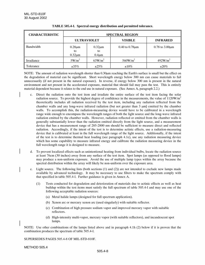
MIL-STD-810F30 August 2002
METHOD 505.4505.4-8
TABLE 505.4-I. Spectral energy distribution and permitted tolerance.
CHARACTERISTIC SPECTRAL REGION
ULTRAVIOLET VISIBLE INFRARED
Bandwidth 0.28µmto
0.32µm
0.32µmto
0.4µm
0.40 to 0.78µm 0.78 to 3.00µm
Irradiance 5W/m2 63W/m2 560W/m2 492W/m2
Tolerance ±35% ±25% ±10% ±20%
NOTE: The amount of radiation wavelength shorter than 0.30µm reaching the Earth's surface is small but the effect onthe degradation of material can be significant. Short wavelength energy below 300 nm can cause materials to failunnecessarily (if not present in the natural exposure). In reverse, if energy below 300 nm is present in the naturalenvironment and not present in the accelerated exposure, material that should fail may pass the test. This is entirelymaterial dependent because it relates to the end use in natural exposure. (See Annex A, paragraph 2.2.)
c. Direct the radiation onto the test item and irradiate the entire surface of the test item facing the solarradiation source. To provide the highest degree of confidence in the measurements, the value of 1120W/m2
theoretically includes all radiation received by the test item, including any radiation reflected from thechamber walls and any long-wave infrared radiation (but not greater than 3 µm) emitted by the chamberwalls. To accomplish this, the radiation-measuring device would have to be calibrated in a wavelengthrange wide enough to encompass the wavelength ranges of both the light source and the long-wave infraredradiation emitted by the chamber walls. However, radiation reflected or emitted from the chamber walls isgenerally substantially lower than the radiation emitted directly from the light source, and a measurementdevice that has a measurement range of 285-2800 nm should be sufficient to measure direct and reflectedradiation. Accordingly, if the intent of the test is to determine actinic effects, use a radiation-measuringdevice that is calibrated at least in the full wavelength range of the light source. Additionally, if the intentof the test is to determine thermal heat loading (see paragraph 4.1e), use any radiation measuring devicewhich has some capability to measure infrared energy and calibrate the radiation measuring device in thefull wavelength range it is designed to measure.
d. To prevent localized effects such as unintentional heating from individual bulbs, locate the radiation sourceat least 76cm (30 inches) away from any surface of the test item. Spot lamps (as opposed to flood lamps)may produce a non-uniform exposure. Avoid the use of multiple lamp types within the array because thespectral distribution within the array will likely be non-uniform over the exposure area.
e. Light source. The following lists (both sections (1) and (2)) are not intended to exclude new lamps madeavailable by advanced technology. It may be necessary to use filters to make the spectrum comply withthat specified in table 505.4-I. Further guidance is given in Annex A.
(1) Tests conducted for degradation and deterioration of materials due to actinic effects as well as heatbuildup within the test items must satisfy the full spectrum of table 505.4-I and may use one of thefollowing acceptable radiation sources:
(a) Metal halide lamps (designed for full spectrum application).
(b) Xenon arc or mercury xenon arc (used singularly) with suitable reflector.
(c) Combination of high pressure sodium vapor and improved mercury vapor with suitablereflectors.
(d) High-intensity multi-vapor, mercury vapor (with suitable reflectors), and incandescent spotlamps.
NOTE: Use other combinations of the lamps listed above and in paragraph 4.1h (2) below if it is proven that thecombination produces the spectrum of table 505.4-I.
SUPERSEDES PAGES 505.4-8 OF MIL-STD-810F.
MIL-STD-810F30 August 2002
METHOD 505.4505.4-9
(2) Use the appropriate lamps from the following list for tests conducted to assess heating effects alone(and not actinic effects).
(a) Mercury vapor lamps (internal reflector type only).
(b) Combination of incandescent spot and tubular-type mercury vapor lamps w/ external reflectors.
(c) Combination of incandescent spot lamps and mercury vapor lamps with internal reflectors.
(d) Metal halide.
(e) Xenon arc or mercury xenon arc lamps with suitable reflectors.
(f) Multi-vapor (clear or coated bulb) with suitable reflectors.
(g) Tungsten filament lamps.
(h) Any other heat producing lamp (see paragraph 4.1e)
4.2 Controls.
a. Temperature. Maintain the chamber air temperature (as specified in the test plan) in accordance with PartOne, paragraph 5.2a. In order to adequately measure the temperature of the air surrounding the test item,measure it (with adequate shielding from radiated heat) at a point or points in a horizontal reference planeat the approximate elevation of the upper surface of the test item, and as close as possible to the test item,making adequate provision for shielding from the effects of radiant heat from the test item. This is one wayto ensure reasonable control of the envelope of air surrounding the test item. The temperature sensors usedto measure the thermal response of the test item will also be affected by direct radiation of the light source.When practical, mount these sensors to the inside surface of the external case (upper surface) of the testitem.
b. Surface contamination. Dust and other surface contamination may significantly change the absorptioncharacteristics of irradiated surfaces. Unless otherwise required, ensure the test items are clean when theyare tested. However, if the effects of surface contamination are to be assessed, include in the relevantrequirements document the necessary information on preparation of surfaces.
c. Instrumentation. Use a pyranometer, pyrheliometer or other suitable device to measure the total radiatedenergy imposed on the test item. Use a pyranometer with suitable filters or a spectroradiometer to measurethe spectral distribution of the radiation imposed on the test item. A filtered pyranometer can only providean approximate measurement of the spectral distribution. However, a spectroradiometer, although moredelicate to employ, can provide a precise measurement of the spectral distribution. Use other measuringinstruments only if they can satisfy the required specifications. Refer to the table below for the requiredmeasurement accuracy of these commonly used instruments. For a pyranometer, the following applies1:
Spectral Range: 280 - 2,500 (better 3,000) nmDirectional Error (cosine error): < +/-1%Non Linearity: <1.5%Tilt Effect (use at tilted surfaces): <1.5%Operating temperature: -40C to +80CTemperature dependence of sensitivity: +/-2% (-10C to +40C)
SUPERSEDES PAGE 505.4-9 OF MIL-STD-810F.
1 These requirements correspond to a ISO 9060 secondary standard instrument as manufactured by several well-known manufacturers.
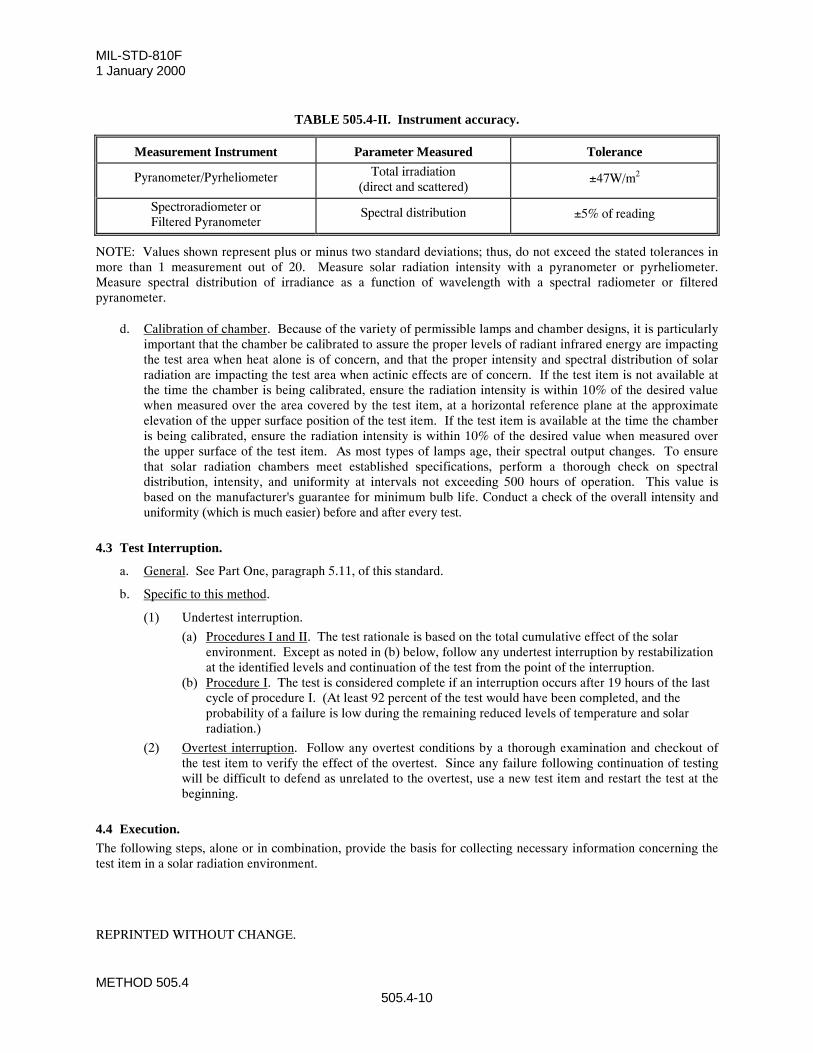
MIL-STD-810F1 January 2000
METHOD 505.4505.4-10
TABLE 505.4-II. Instrument accuracy.
Measurement Instrument Parameter Measured Tolerance
Pyranometer/Pyrheliometer Total irradiation(direct and scattered)
±47W/m2
Spectroradiometer orFiltered Pyranometer
Spectral distribution ±5% of reading
NOTE: Values shown represent plus or minus two standard deviations; thus, do not exceed the stated tolerances inmore than 1 measurement out of 20. Measure solar radiation intensity with a pyranometer or pyrheliometer.Measure spectral distribution of irradiance as a function of wavelength with a spectral radiometer or filteredpyranometer.
d. Calibration of chamber. Because of the variety of permissible lamps and chamber designs, it is particularlyimportant that the chamber be calibrated to assure the proper levels of radiant infrared energy are impactingthe test area when heat alone is of concern, and that the proper intensity and spectral distribution of solarradiation are impacting the test area when actinic effects are of concern. If the test item is not available atthe time the chamber is being calibrated, ensure the radiation intensity is within 10% of the desired valuewhen measured over the area covered by the test item, at a horizontal reference plane at the approximateelevation of the upper surface position of the test item. If the test item is available at the time the chamberis being calibrated, ensure the radiation intensity is within 10% of the desired value when measured overthe upper surface of the test item. As most types of lamps age, their spectral output changes. To ensurethat solar radiation chambers meet established specifications, perform a thorough check on spectraldistribution, intensity, and uniformity at intervals not exceeding 500 hours of operation. This value isbased on the manufacturer's guarantee for minimum bulb life. Conduct a check of the overall intensity anduniformity (which is much easier) before and after every test.
4.3 Test Interruption.
a. General. See Part One, paragraph 5.11, of this standard.
b. Specific to this method.
(1) Undertest interruption.
(a) Procedures I and II. The test rationale is based on the total cumulative effect of the solarenvironment. Except as noted in (b) below, follow any undertest interruption by restabilizationat the identified levels and continuation of the test from the point of the interruption.
(b) Procedure I. The test is considered complete if an interruption occurs after 19 hours of the lastcycle of procedure I. (At least 92 percent of the test would have been completed, and theprobability of a failure is low during the remaining reduced levels of temperature and solarradiation.)
(2) Overtest interruption. Follow any overtest conditions by a thorough examination and checkout ofthe test item to verify the effect of the overtest. Since any failure following continuation of testingwill be difficult to defend as unrelated to the overtest, use a new test item and restart the test at thebeginning.
4.4 Execution.The following steps, alone or in combination, provide the basis for collecting necessary information concerning thetest item in a solar radiation environment.
REPRINTED WITHOUT CHANGE.
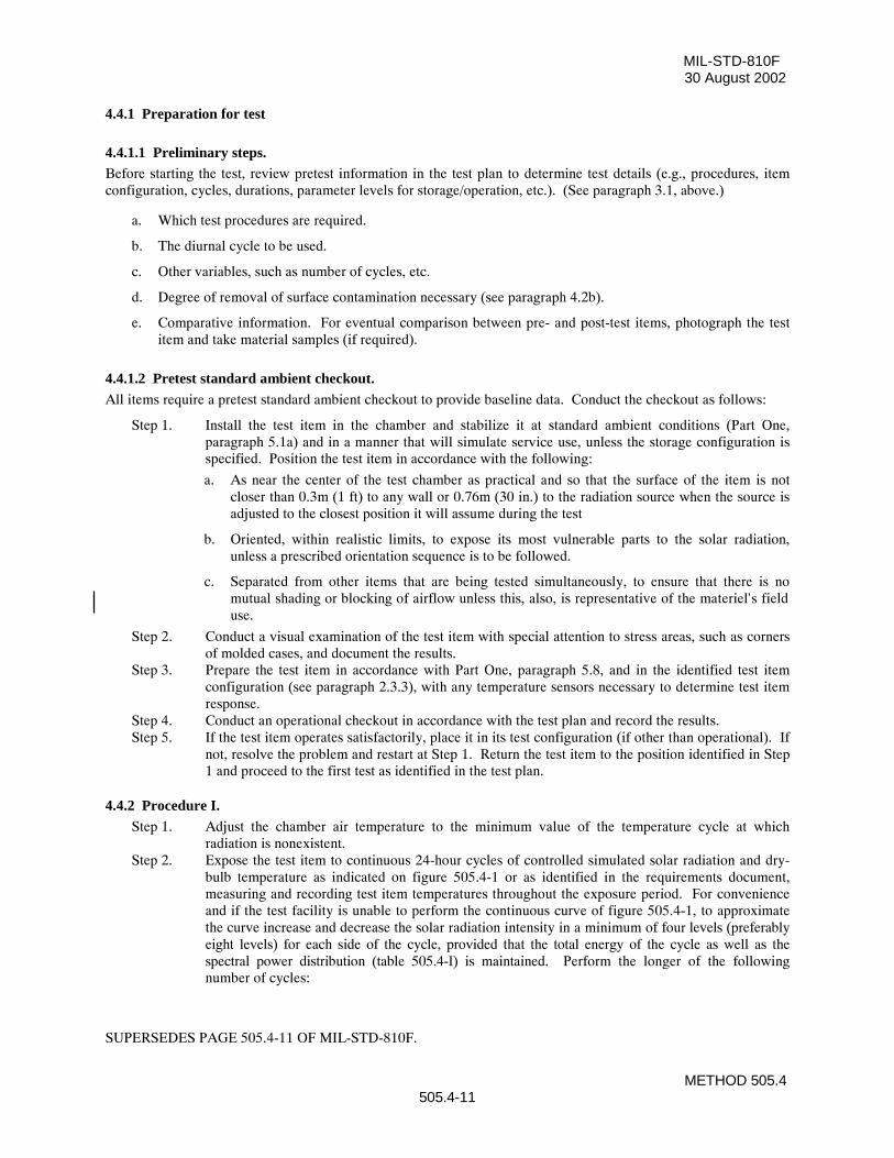
MIL-STD-810F30 August 2002
METHOD 505.4505.4-11
4.4.1 Preparation for test
4.4.1.1 Preliminary steps.Before starting the test, review pretest information in the test plan to determine test details (e.g., procedures, itemconfiguration, cycles, durations, parameter levels for storage/operation, etc.). (See paragraph 3.1, above.)
a. Which test procedures are required.
b. The diurnal cycle to be used.
c. Other variables, such as number of cycles, etc.
d. Degree of removal of surface contamination necessary (see paragraph 4.2b).
e. Comparative information. For eventual comparison between pre- and post-test items, photograph the testitem and take material samples (if required).
4.4.1.2 Pretest standard ambient checkout.All items require a pretest standard ambient checkout to provide baseline data. Conduct the checkout as follows:
Step 1. Install the test item in the chamber and stabilize it at standard ambient conditions (Part One,paragraph 5.1a) and in a manner that will simulate service use, unless the storage configuration isspecified. Position the test item in accordance with the following:
a. As near the center of the test chamber as practical and so that the surface of the item is notcloser than 0.3m (1 ft) to any wall or 0.76m (30 in.) to the radiation source when the source isadjusted to the closest position it will assume during the test
b. Oriented, within realistic limits, to expose its most vulnerable parts to the solar radiation,unless a prescribed orientation sequence is to be followed.
c. Separated from other items that are being tested simultaneously, to ensure that there is nomutual shading or blocking of airflow unless this, also, is representative of the materiel's fielduse.
Step 2. Conduct a visual examination of the test item with special attention to stress areas, such as cornersof molded cases, and document the results.
Step 3. Prepare the test item in accordance with Part One, paragraph 5.8, and in the identified test itemconfiguration (see paragraph 2.3.3), with any temperature sensors necessary to determine test itemresponse.
Step 4. Conduct an operational checkout in accordance with the test plan and record the results.Step 5. If the test item operates satisfactorily, place it in its test configuration (if other than operational). If
not, resolve the problem and restart at Step 1. Return the test item to the position identified in Step1 and proceed to the first test as identified in the test plan.
4.4.2 Procedure I.Step 1. Adjust the chamber air temperature to the minimum value of the temperature cycle at which
radiation is nonexistent.Step 2. Expose the test item to continuous 24-hour cycles of controlled simulated solar radiation and dry-
bulb temperature as indicated on figure 505.4-1 or as identified in the requirements document,measuring and recording test item temperatures throughout the exposure period. For convenienceand if the test facility is unable to perform the continuous curve of figure 505.4-1, to approximatethe curve increase and decrease the solar radiation intensity in a minimum of four levels (preferablyeight levels) for each side of the cycle, provided that the total energy of the cycle as well as thespectral power distribution (table 505.4-I) is maintained. Perform the longer of the followingnumber of cycles:
SUPERSEDES PAGE 505.4-11 OF MIL-STD-810F.
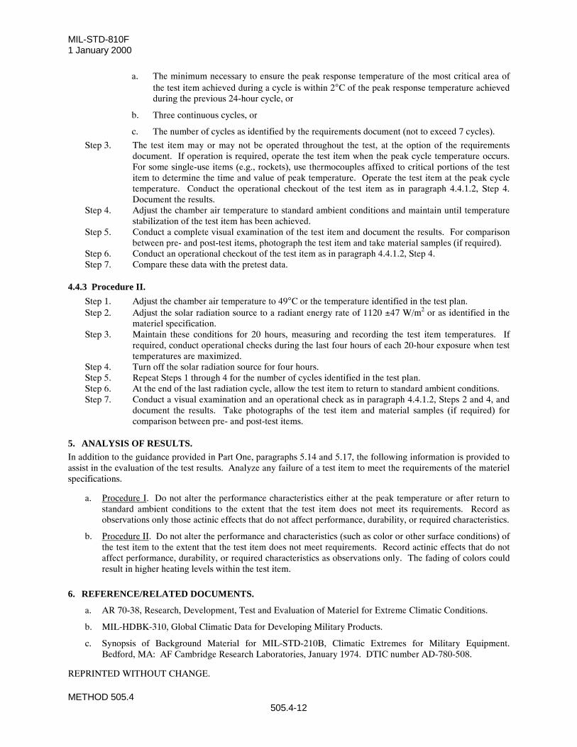
MIL-STD-810F 1 January 2000
METHOD 505.4505.4-12
a. The minimum necessary to ensure the peak response temperature of the most critical area ofthe test item achieved during a cycle is within 2°C of the peak response temperature achievedduring the previous 24-hour cycle, or
b. Three continuous cycles, or
c. The number of cycles as identified by the requirements document (not to exceed 7 cycles).
Step 3. The test item may or may not be operated throughout the test, at the option of the requirementsdocument. If operation is required, operate the test item when the peak cycle temperature occurs.For some single-use items (e.g., rockets), use thermocouples affixed to critical portions of the testitem to determine the time and value of peak temperature. Operate the test item at the peak cycletemperature. Conduct the operational checkout of the test item as in paragraph 4.4.1.2, Step 4.Document the results.
Step 4. Adjust the chamber air temperature to standard ambient conditions and maintain until temperaturestabilization of the test item has been achieved.
Step 5. Conduct a complete visual examination of the test item and document the results. For comparisonbetween pre- and post-test items, photograph the test item and take material samples (if required).
Step 6. Conduct an operational checkout of the test item as in paragraph 4.4.1.2, Step 4.Step 7. Compare these data with the pretest data.
4.4.3 Procedure II.
Step 1. Adjust the chamber air temperature to 49°C or the temperature identified in the test plan.Step 2. Adjust the solar radiation source to a radiant energy rate of 1120 ±47 W/m2 or as identified in the
materiel specification.Step 3. Maintain these conditions for 20 hours, measuring and recording the test item temperatures. If
required, conduct operational checks during the last four hours of each 20-hour exposure when testtemperatures are maximized.
Step 4. Turn off the solar radiation source for four hours.Step 5. Repeat Steps 1 through 4 for the number of cycles identified in the test plan.Step 6. At the end of the last radiation cycle, allow the test item to return to standard ambient conditions.Step 7. Conduct a visual examination and an operational check as in paragraph 4.4.1.2, Steps 2 and 4, and
document the results. Take photographs of the test item and material samples (if required) forcomparison between pre- and post-test items.
5. ANALYSIS OF RESULTS.In addition to the guidance provided in Part One, paragraphs 5.14 and 5.17, the following information is provided toassist in the evaluation of the test results. Analyze any failure of a test item to meet the requirements of the materielspecifications.
a. Procedure I. Do not alter the performance characteristics either at the peak temperature or after return tostandard ambient conditions to the extent that the test item does not meet its requirements. Record asobservations only those actinic effects that do not affect performance, durability, or required characteristics.
b. Procedure II. Do not alter the performance and characteristics (such as color or other surface conditions) ofthe test item to the extent that the test item does not meet requirements. Record actinic effects that do notaffect performance, durability, or required characteristics as observations only. The fading of colors couldresult in higher heating levels within the test item.
6. REFERENCE/RELATED DOCUMENTS.
a. AR 70-38, Research, Development, Test and Evaluation of Materiel for Extreme Climatic Conditions.
b. MIL-HDBK-310, Global Climatic Data for Developing Military Products.
c. Synopsis of Background Material for MIL-STD-210B, Climatic Extremes for Military Equipment.Bedford, MA: AF Cambridge Research Laboratories, January 1974. DTIC number AD-780-508.
REPRINTED WITHOUT CHANGE.
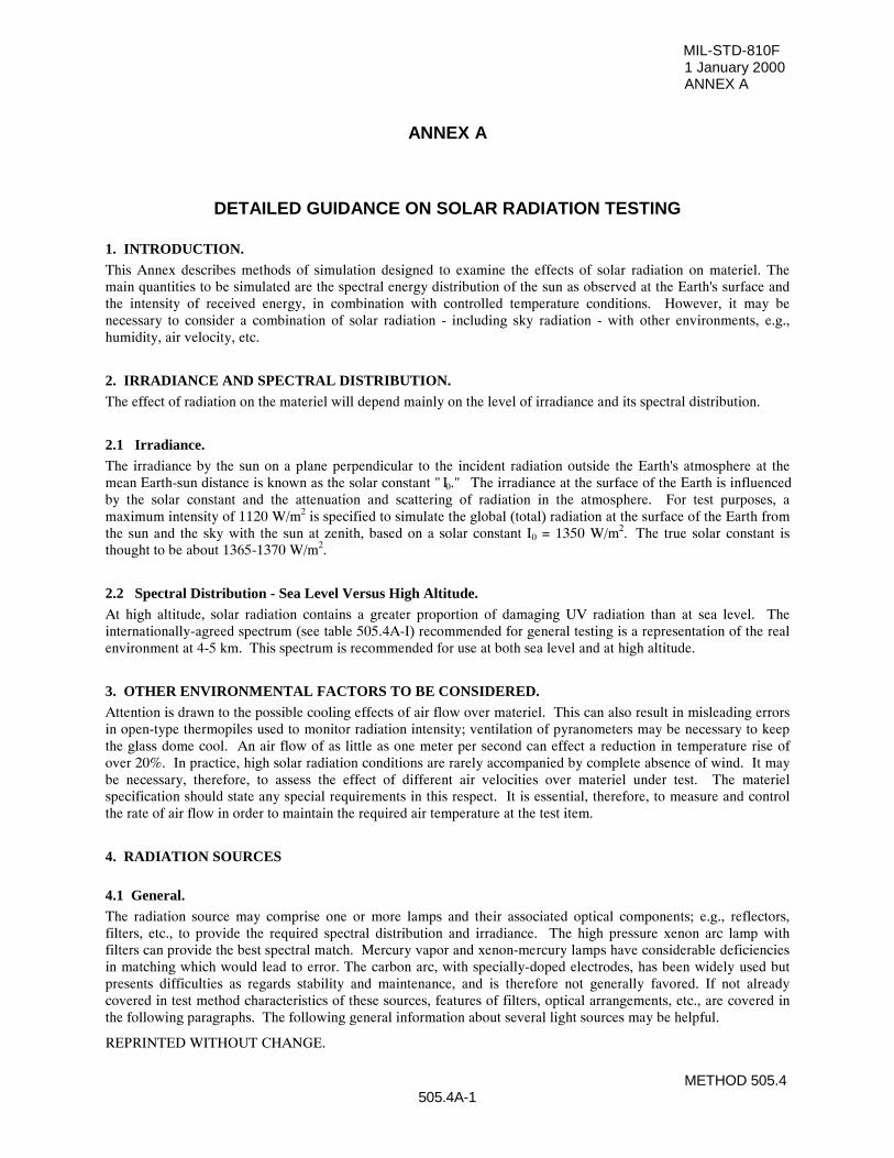
MIL-STD-810F1 January 2000ANNEX A
METHOD 505.4505.4A-1
ANNEX A
DETAILED GUIDANCE ON SOLAR RADIATION TESTING
1. INTRODUCTION.This Annex describes methods of simulation designed to examine the effects of solar radiation on materiel. Themain quantities to be simulated are the spectral energy distribution of the sun as observed at the Earth's surface andthe intensity of received energy, in combination with controlled temperature conditions. However, it may benecessary to consider a combination of solar radiation - including sky radiation - with other environments, e.g.,humidity, air velocity, etc.
2. IRRADIANCE AND SPECTRAL DISTRIBUTION.The effect of radiation on the materiel will depend mainly on the level of irradiance and its spectral distribution.
2.1 Irradiance.The irradiance by the sun on a plane perpendicular to the incident radiation outside the Earth's atmosphere at themean Earth-sun distance is known as the solar constant " I0." The irradiance at the surface of the Earth is influencedby the solar constant and the attenuation and scattering of radiation in the atmosphere. For test purposes, amaximum intensity of 1120 W/m2 is specified to simulate the global (total) radiation at the surface of the Earth fromthe sun and the sky with the sun at zenith, based on a solar constant I0 = 1350 W/m2. The true solar constant isthought to be about 1365-1370 W/m2.
2.2 Spectral Distribution - Sea Level Versus High Altitude.At high altitude, solar radiation contains a greater proportion of damaging UV radiation than at sea level. Theinternationally-agreed spectrum (see table 505.4A-I) recommended for general testing is a representation of the realenvironment at 4-5 km. This spectrum is recommended for use at both sea level and at high altitude.
3. OTHER ENVIRONMENTAL FACTORS TO BE CONSIDERED.Attention is drawn to the possible cooling effects of air flow over materiel. This can also result in misleading errorsin open-type thermopiles used to monitor radiation intensity; ventilation of pyranometers may be necessary to keepthe glass dome cool. An air flow of as little as one meter per second can effect a reduction in temperature rise ofover 20%. In practice, high solar radiation conditions are rarely accompanied by complete absence of wind. It maybe necessary, therefore, to assess the effect of different air velocities over materiel under test. The materielspecification should state any special requirements in this respect. It is essential, therefore, to measure and controlthe rate of air flow in order to maintain the required air temperature at the test item.
4. RADIATION SOURCES
4.1 General.The radiation source may comprise one or more lamps and their associated optical components; e.g., reflectors,filters, etc., to provide the required spectral distribution and irradiance. The high pressure xenon arc lamp withfilters can provide the best spectral match. Mercury vapor and xenon-mercury lamps have considerable deficienciesin matching which would lead to error. The carbon arc, with specially-doped electrodes, has been widely used butpresents difficulties as regards stability and maintenance, and is therefore not generally favored. If not alreadycovered in test method characteristics of these sources, features of filters, optical arrangements, etc., are covered inthe following paragraphs. The following general information about several light sources may be helpful.
REPRINTED WITHOUT CHANGE.
MIL-STD-810F 30 August 2002ANNEX A
METHOD 505.4505.4A-2
a. Xenon lamps. The configuration and size of the lamp(s) used will depend on the test required. The relativespectral distribution of the xenon arc radiation has been found to be substantially independent of lamppower. However, variation of lamp power will change the temperature of the electrodes and hence thespectral distribution of their radiation. With long arc lamps, it is relatively simple to mask off the electroderadiation. The form of construction of the short arc lamp leads to considerably wider manufacturingvariation compared with the long arc, a point particularly important when replacement becomes necessary.Routine replacement of either type of lamp will be needed, since the emission will change continuouslywith life, and there may be wide variations of the life characteristic from lamp to lamp.
b. Metal Halide (HMI). Although this lamp imparts more energy in the ultraviolet range and low visiblerange than specified in table 505.4-I, it provides a good source for tests requiring attention to thermaleffects, since the additional UV energy represents less than one per cent of the total energy, and tests forheating effects are generally sufficiently short in duration that actinic degradation will not be a concern. Fortesting actinic effects, the energy level in the heating range will be lower than specified as the UV levelswill be adjusted to table 505.4A-I levels. Since the energy level between 0.32 and 0.40µm increases sharplyas the lamp power level is reduced, power cannot be used to adjust overall energy levels once the desireddistribution has been obtained.
4.2 Filters.
Liquid filters have certain disadvantages such as the possibility of boiling, the temperature coefficient of spectraltransmission, and long term drift in spectral character. The present preference is for glass filters to be used, althoughthe characteristics of glass filters are not as accurately reproduced as those of a chemical solution filter. Some trialand error may be necessary to compensate for different optical densities by using different plate thicknesses. Glassfilters are proprietary articles and manufacturers should be consulted concerning the choice of filters suitable forparticular purposes. The choice will depend on the source and its methods of use. For example, a xenon source maybe test-compensated by a combination of infrared and ultraviolet absorbing filters. Some glass infrared filters maybe prone to rapid changes in spectral characteristics when exposed to excessive ultraviolet radiation. Thisdeterioration may be largely prevented by interposing the ultraviolet filter between the source and the infrared filter.Interference type filters, which function by reflecting instead of absorbing the unwanted radiation, (thus resulting inreduced heating of the glass), are generally more stable than absorption filters.
4.3 Uniformity of Irradiance.
Owing to the distance of the sun from the Earth, solar radiation appears at the Earth's surface as an essentiallyparallel beam. Artificial sources are relatively close to the working surface and means of directing and focusing thebeam must be provided with the aim of achieving a uniform irradiance at the measurement plane withinspecification limits (i.e., 1120 W/m2 (+10, -0 W/m2)). This is difficult to achieve with a short-arc xenon lamp with aparabolic reflector because of shadows from the lamp electrodes and supports. Also, the incandescence of the anodecan produce considerable radiation at a much lower color temperature, slightly displaced from the main beam, ifonly the arc itself is at the focus of the reflector. Uniform irradiation is more readily achieved with a long arc lampmounted in a parabolic 'trough' type reflector. However, by employing very elaborate mounting techniques, it ispossible to irradiate, with some degree of uniformity, a large surface by a number of short arc xenon lamps. It isgenerally advisable to locate radiation source(s) outside the test enclosure or chamber. This avoids possibledegradation of the optical components, e.g., by high humidity conditions, and contamination of test items by ozonethat has been generated by xenon and other types of arc lamps. Precise collimation of the radiation beam is notnormally required except for testing special materiel such as solar cells, solar tracking devices, etc. However, some
SUPERSEDES PAGE 505.4A-2 OF MIL-STD-810F.
MIL-STD-810F30 August 2002
METHOD 506.4506.4-1
METHOD 506.4
RAINNOTE: Tailoring is essential. Select methods, procedures, and parameter levels based on the tailoring processdescribed in Part One, paragraph 4.2.2, and Appendix C. Apply the general guidelines for laboratory test methodsdescribed in Part One, paragraph 5 of this standard.
1. SCOPE.
1.1 Purpose.The purpose of this method is to help determine the following with respect to rain, water spray, or dripping water:
a. The effectiveness of protective covers, cases, and seals in preventing the penetration of water into themateriel.
b. The capability of the materiel to satisfy its performance requirements during and after exposure to water.
c. Any physical deterioration of the materiel caused by the rain.
d. The effectiveness of any water removal system.
e. The effectiveness of protection offered to a packaged materiel.
1.2 Application.Use this method to evaluate materiel likely to be exposed to rain, water spray, or dripping water during storage,transit, or operation. If the materiel configuration is the same, the immersion (leakage) test (method 512.4) isnormally considered to be a more severe test for determining if water will penetrate materiel. There is generally noneed to subject materiel to a rain test if it has previously passed the immersion test and the configuration does notchange. However, there are documented situations in which rain tests revealed problems not observed duringimmersion tests due to differential pressure. Additionally, the immersion test may be more appropriate if themateriel is likely to be placed on surfaces with significant amounts of standing water. In most cases, both testsshould be performed if appropriately identified in the life-cycle profile.
1.3 Limitations.Where a requirement exists for determining the effects of rain erosion on radomes, nose cones, fuzes, etc., considerusing a rocket sled test facility or other such facility. Since any test procedure involved would be contingent onrequirements peculiar to the materiel and the facility employed, a standardized test procedure for rain erosion is notincluded in this method. Because of the finite size of the test facilities, it may be difficult to determine atmosphericrain effects such as on electromagnetic radiation and propagation. This method is not intended for use in evaluatingthe adequacy of aircraft windshield rain removal provisions, nor does it address pressure washers ordecontamination devices. Additionally, this method may not be adequate for determining the effects of extendedperiods of exposure to rain, or for evaluating materiel exposed to only light condensation drip rates (lower than140 L/m2/hr) caused by an overhead surface. For this latter case, the aggravated humidity cycle of method 507.4will induce a significant amount of free water on both inside and outside surfaces.
2. TAILORING GUIDANCE.
2.1 Selecting the Rain Method.After examining the requirements documents and applying the tailoring process in Part One of this standard todetermine where rain is foreseen in the life cycle of the materiel, use the following to aid in selecting this methodand placing it in sequence with other methods. The term " rain " encompasses the full range of " free water"(blowing, steady-state, drip) tests included in this method.
SUPERSEDES PAGE 506.4-1 OF MIL-STD-810F.
MIL-STD-810F 1 January 2000
METHOD 506.4506.4-2
2.1.1 Effects of rain environments.Rain (when falling, upon impact, and as deposited as pooled water) has a variety of effects on materiel. Consider thefollowing typical problems to help determine if this method is appropriate for the materiel being tested. This list is notintended to be all-inclusive and some of the examples may overlap the categories.
2.1.1.1 In the atmosphere.In the atmosphere the effects resulting from exposure to these environments include:
a. Interference with or degradation of radio communication.
b. Limited radar effectiveness.
c. Limited aircraft operations due to restricted visibility and decreased lift from wing surfaces (excessive rainrates only).
d. Damage to aircraft in flight.
e. Effect on artillery and missile launching.
f. Degradation or negation of optical surveillance.
g. Decreased effectiveness of personnel in exposed activities.
h. Premature functioning of some fuses.
i. Inhibited visibility through optical devices.
2.1.1.2 On impact.On impact it erodes surfaces.
2.1.1.3 After deposition and/or penetration.After deposition and/or penetration, the effects resulting from exposure to these environments include:
a. Degraded strength/swelling of some materials.
b. Increased corrosion potential, erosion, or even fungal growth.
c. Increased weight.
d. Electrical or electronic apparatus become inoperative or unsafe.
e. Malfunction of electrical materiel.
f. Freezing inside materiel that may cause delayed deterioration and malfunction by swelling or cracking ofparts.
g. Modified thermal exchange.
h. Slower burning of propellants.
2.1.2 Sequence among other methods.
a. General. See Part One, paragraph 5.5.
b. Unique to this method. This method is applicable at any stage in the test program, but its effectiveness indetermining the integrity of an enclosure is maximized if it is performed after the dynamic tests.
2.2 Selecting Procedures.This method includes three rain-related test procedures: Procedure I (Rain and Blowing Rain), Procedure II(Watertightness), and Procedure III (Drip). Before conducting the test, determine which test procedure(s) and testconditions are appropriate.
REPRINTED WITHOUT CHANGE.
MIL-STD-810F30 August 2002
METHOD 506.4506.4-3
2.2.1 Procedure selection considerations.Differences among rain test procedures are explained below. Select the procedure that represents the most severeexposure anticipated for the materiel commensurate with materiel size. When selecting a procedure, consider:
a. The materiel configuration.b. The logistical and operational requirements (purpose) of the materiel.c. The operational purpose of the materiel and data to verify it has been met.d. The natural exposure circumstances.e. Procedure sequence.
2.2.2 Difference among procedures.a. Procedure I - Rain and Blowing Rain. Procedure I is applicable for materiel which will be deployed out-of-
doors and which will be unprotected from rain or blowing rain. The accompanying wind velocity can varyfrom almost calm to extremely high. Consider using Procedure II for materiel that cannot be adequatelytested with this procedure because of its (large) size.
b. Procedure II - Watertightness. Consider Procedure II when large (shelter-size) materiel is to be tested and ablowing-rain facility is not available or practical. This procedure is not intended to simulate natural rainfallbut will provide a high degree of confidence in the watertightness of materiel.
c. Procedure III - Drip. Procedure III is appropriate when materiel is normally protected from rain but maybe exposed to falling water from condensation or leakage from upper surfaces. There are two variations tothe drip test: (1) for materiel that may experience falling water (generally from condensation), and (2) formateriel that may be subjected to heavy condensation or leaks from above.
2.3 Determine Test Levels and Conditions.Having selected this method and relevant procedures (based on the materiel's requirements documents and thetailoring process), it is necessary to complete the tailoring process by selecting specific parameter levels and specialtest conditions/techniques for these procedures based on requirements documents, Life Cycle Environmental Profile,Operational Environment Documentation (see Part One, Figure 1-1), and information provided with this procedure.From these sources of information, determine the functions to be performed by the materiel in rain environments orfollowing storage in rain environments. Then determine the rainfall levels of the geographical areas and micro-environments in which the materiel is designed to be employed. Variables under each test procedure include the testitem configuration, rainfall rate, wind velocity, test item exposure surfaces, water pressure, and any additionalappropriate guidelines in accordance with the requirements document.
2.3.1 Test item configuration.Perform the test using all the configurations in which the materiel may be placed during its life cycle. As aminimum, consider the following configurations:
a. In a shipping/storage container or transit case.b. Protected or not protected.c. In its operational configuration.d. Modified with kits for special applications.
NOTE: Do not use any sealing, taping, caulking, etc., except as required by the design specification for the materiel.Unless otherwise specified, do not use test items that have surface contamination such as oil, grease, or dirt, whichcould prevent wetting.
2.3.2 Rainfall rate.The rainfall rate used in Procedure I may be tailored to the anticipated deployment locale and duration. Althoughvarious rainfall intensities have been measured in areas of heavy rainfall, recommend a minimum rate of1.7 mm/min (4 in/hr) since it is not an uncommon occurrence and would provide a reasonable degree of confidencein the materiel. MIL-HDBK-310 contains further information.
SUPERSEDES PAGE 506.4-3 OF MIL-STD-810F.
MIL-STD-810F30 August 2002
METHOD 506.4506.4-4
2.3.3 Droplet size.Nominal drop-size spectra exist for instantaneous rainfall rates but for the long-term rainfall rates they aremeaningless since rates are made up of many different instantaneous rates possessing different spectra (reference b).For Procedures I and II, use droplet sizes predominantly in the range of approximately 0.5 mm in diameter 1/ (whichis considered to be mist or drizzle rather than rain (reference e), to 4.5 mm in diameter (reference i). For drip testsusing dispensing tubes (figure 506.4-1), polyethylene tubing sleeves added to the dispensing tubes will increase thedroplet size to its maximum.
NOTE: Observations have shown that water droplets introduced into a high velocity air stream tend to break upover distance (references j and k). Accordingly, recommend introducing the droplets as close as possible to the testitem while assuring the droplets achieve the required velocity prior to impact with the test item.
2.3.4 Wind velocity.High rainfall intensities accompanied by winds of 18 m/s (40 mph) are not uncommon during storms. Unlessotherwise specified or when steady-state conditions are specified, recommend this velocity. Where facilitylimitations preclude the use of wind, use Procedure II.
2.3.5 Test item exposure surface (orientation).Wind-blown rain will usually have more of an effect on vertical surfaces than on horizontal surfaces, and vice versafor vertical or near-vertical rain. Expose all surfaces onto which the rain could fall or be driven to the testconditions. Rotate the item as required to expose all vulnerable surfaces.
2.3.6 Water pressure.Procedure II relies on pressurized water. Vary the pressure as necessary to comply with the requirement’sdocuments, but a minimum value of 276 kPa (40 psig) nozzle pressure is given as a guideline based on pastexperience. This value will produce water droplets traveling at approximately 64 km/h (40 mph) when a nozzle asspecified in paragraph 4.1.2 is used.
2.3.7 Preheat temperature.Experience has shown that a temperature differential between the test item and the rainwater can affect the results ofa rain test. When specified for nominally sealed items, increasing the test item temperature to about 10°C higherthan the rain temperature at the beginning of each exposure period to subsequently produce a negative pressureinside the test item will provide a more reliable verification of its watertightness. Ensure the heating time is theminimum required to stabilize the test item temperature, and not sufficient to dry the test item when not openedbetween exposures.
2.3.8 Exposure duration.Determine the exposure duration from the life-cycle profile, but do not use a duration less than that specified in theindividual procedures. For items made of material that may absorb moisture, the duration may have to besignificantly extended to reflect real life-cycle circumstances and, for drip tests, the drip rate appropriately reduced.With certain materials, the water penetration and thus the degradation is more a function of time (length ofexposure) than the volume or rain/drip rate exposure.
3. INFORMATION REQUIRED.
3.1 Pretest.The following information is required to conduct rain tests adequately.
a. General. Information listed in Part One, paragraphs 5.7 and 5.9; and Appendix A, Task 405, of thisstandard.
1/Observations show there are no drops of less than roughly 0.5 mm diameter during intense rains (reference c).
SUPERSEDES PAGE 506.4-4 OF MIL-STD-810F.
MIL-STD-810F30 August 2002
METHOD 506.4506.4-5
b. Specific to this method.
(1) Rainfall rate.
(2) Exposure surfaces/duration.
(3) Test item preheat temperature.
(4) Initial water temperature.
(5) Wind velocity.
(6) Water pressure (if appropriate).
3.2 During Test.For test validation purposes, record deviations from planned or pre-test procedures or parameter levels, includingany procedural anomalies that may occur.
3.3 Post-test.Record the following post-test information.
a. General. Information listed in Part One, paragraph. 5.13, and in Appendix A, Task 406 of this standard.
b. Specific to this method.
(1) Surfaces of the test item subjected to rainfall.
(2) Duration of exposure per face.
(3) Results of inspection for water penetration (amount and probable point of entry).
(4) Results of operational checks.
(5) Length of time for each performance check.
4. TEST PROCESS.
4.1 Test Facility.
4.1.1 Procedure I.
a. Use a rain facility capable of producing falling rain at the rate specified herein. To produce the rain, use awater distribution device that produces droplets having a diameter range predominantly between 0.5 mmand 4.5 mm. Ensure the rain is dispersed completely over the test item when accompanied by theprescribed wind. A water-soluble dye such as fluorescein may be added to the rainwater to aid in locatingand analyzing water leaks. For steady-state rain, use either spray nozzles or the apparatus shown onfigure 506.4-1 (with the polyethylene tubing removed), and position the dispenser at a height sufficient toensure the drops approach terminal velocity. It is not necessary to use de-ionized or distilled water for thistest.
b. Position the wind source with respect to the test item so that it will cause the rain to beat directly, withvariations up to 45O from the horizontal, and uniformly against one side of the test item. Use a wind sourcethat can produce horizontal wind velocities equal to and exceeding 18 m/s. Measure the wind velocity atthe position of the test item before placement of the test item in the facility. Do not allow rust or corrosivecontaminants on the test item.
4.1.2 Procedure II.Use nozzles that produce a square spray pattern or other overlapping pattern (for maximum surface coverage) andwith a droplet size predominantly in the 0.5 to 4.5 mm range at approximately 276 kPa. Use at least one nozzle foreach 0.56m2 (6 ft2) of surface area and position each about 48 cm from the test surface. Adjust this distance asnecessary to achieve overlap of the spray patterns. A water-soluble dye such as fluorescein added to the rainwatermay aid in locating and analyzing any water leaks. For Procedure II, position the nozzles as required by the test planor as depicted on figure 506.4-2.
SUPERSEDES PAGE 506.4-5 OF MIL-STD-810F.
MIL-STD-810F30 August 2002
METHOD 506.4506.4-6
4.1.3 Procedure III.Use a test setup that provides a volume of water greater than 280 l/m2/hr (7 gal/ft2/hr) dripping from a dispenser withdrip holes on a 20 to 25.4 mm pattern (depending on which dispenser is used) but without coalescence of the dripsinto a stream. Figures 506.4-1 and 506.4-3 provide possible dispenser designs. Either arrangement shown on figure506.4-1 is recommended over that of figure 506.4-3 due to its simplicity of construction, maintenance, cost, andreproducibility of tests. The polyethylene tubing is optional, but it ensures maximum droplet size. Use a drip heightthat ensures terminal velocity of the droplets (~9 m/s). Use a dispenser with a drip area large enough to cover theentire top surface of the test item. For known conditions where a 280 L/m2/hr drip rate cannot occur, test the itemby reducing the drip rate and increasing the test duration. For example, for an item exposed only to 140 L/m2/hr,appropriately reduce the drip rate as long as the duration of the test is extended to 30 minutes to ensure theequivalent volume of water falls on the test item. A water-soluble dye such as fluorescein added to the rainwatermay aid in location and analysis of water leaks. Recommend the water be filtered using a fine sediment filter toensure particulate buildup does not block the tubing.
4.2 Controls.
a. For Procedures I and II, verify the rainfall rate immediately before each test.
b. For Procedure I, verify the wind velocity immediately before each test.
c. For Procedures I and II, verify the nozzle spray pattern and pressure before each test.
d. For Procedure III, verify the flow rate immediately before and after the test to ensure test tolerances are metthroughout the test, and ensure that only separate (or discrete) drops are issuing from the dispenser.
e. Unless otherwise specified, water used for rain tests can be from local water supply sources.
4.3 Test Interruption.
a. General. See Part One, paragraph 5.11 of this standard.
b. Specific to this method. Interruption of a rain test is unlikely to generate any adverse effects. Normally,continue the test from the point of interruption.
4.4 Execution.The following steps, alone or in combination, provide the basis for collecting necessary information concerning themateriel's watertightness.
4.4.1 Preparation for test.
4.4.1.1 Preliminary steps.Before starting the test, review pretest information in the test plan to determine test details (e.g., procedures, testitem configuration/orientation, cycles, durations, parameter levels for storage/operation, rainfall rates and windvelocities (for Procedures I), etc.). (See paragraph 3.1, above.)
4.4.1.2 Pretest standard ambient checkout.All test items require a pretest standard ambient checkout to provide baseline data. Conduct the checkout asfollows:
Step 1. Stabilize the test item at standard ambient conditions (Part One, paragraph 5.1), in the test chamber,whenever possible.
Step 2. Conduct a complete pretest examination and document the results.Step 3. Prepare the test item in accordance with Part One, paragraph 5.8 and in the required test item
configuration.Step 4. To establish baseline data, conduct an operational checkout in accordance with the test plan, and
record the results.
SUPERSEDES PAGE 506.4-6 OF MIL-STD-810F.
MIL-STD-810F30 August 2002
METHOD 506.4506.4-7
4.4.2 Procedure I - Rain and blowing rain.
Step 1. If the temperature differential between the water and the test item is less than 10°C, either heat thetest item to a higher temperature than the rain water (see paragraph 2.3.7) such that the test itemtemperature has been stabilized at 10 +2°C above the rain water temperature at the start of eachexposure period (see paragraph 2.3.7), or cool the water. Restore the test item to its normaloperating configuration immediately before testing.
Step 2. With the test item in the facility and in its normal operating position, adjust the rainfall rate asspecified in the test plan.
Step 3. Initiate the wind at the velocity specified in the test plan and maintain it for at least 30 minutes.Step 4. If required, operate the test for the last 10 minutes of the 30-minute rain.Step 5. Rotate the test item to expose it to the rain and blowing wind source to any other side of the test
item that could be exposed to blowing rain in its deployment cycle.Step 6. Repeat Steps 1 through 5 until all surfaces have been tested.Step 7. Examine the test item in the test chamber (if possible); otherwise, remove the test item from the test
facility and conduct a visual inspection. If water has penetrated the test item, judgment must beused before operation of the test item. It may be necessary to empty water from the test item (andmeasure the quantity) to prevent a safety hazard.
Step 8. Measure and document any free water found inside the protected areas of the test item.Step 9. If required, operate the test item for compliance with the requirements document, and document the
results.
4.4.3 Procedure II - Watertightness.Step 1. Install the test item in the test facility with all doors, louvers, etc., closed.Step 2. Position the nozzles as required by the test plan or as indicated on figure 506.4-2.Step 3. Spray all exposed surfaces of the test item with water for not less than 40 minutes per face.Step 4. After each 40-minute spray period, inspect the interior of the test item for evidence of free water.
Estimate its volume and the probable point of entry and document.Step 5. Conduct an operational check of the test item as specified in the test plan, and document the results.
4.4.4 Procedure III - Drip.
Step 1. Install the test item in the facility in accordance with Part One, paragraph 5.8 and in its operationalconfiguration with all connectors and fittings engaged. Ensure the temperature differential betweenthe test item and the water is 10°C or greater. If necessary, either raise the test item temperature orlower the water temperature to achieve the differential in paragraph 2.3.7, and restore the test itemto its normal operating configuration immediately before testing.
Step 2. With the test item operating, subject it to water falling from a specified height (no less than 1 meter(3 feet)) as measured from the upper main surface of the test item at a uniform rate for 15 minutesor as otherwise specified (see figure 506.4-1 or figure 506.4-3). Use a test setup that ensures thatall of the upper surfaces get droplets on them at some time during the test. For test items withglass-covered instruments, tilt them at a 45° angle, dial up.
Step 3. At the conclusion of the 15-minute exposure, remove the test item from the test facility and removesufficient panels or covers to allow the interior to be seen.
Step 4. Visually inspect the test item for evidence of water penetration.Step 5. Measure and document any free water inside the test item.Step 6. Conduct an operational check of the test item as specified in the test plan, and document the results.
SUPERSEDES PAGE 506.4-7 OF MIL-STD-810F.
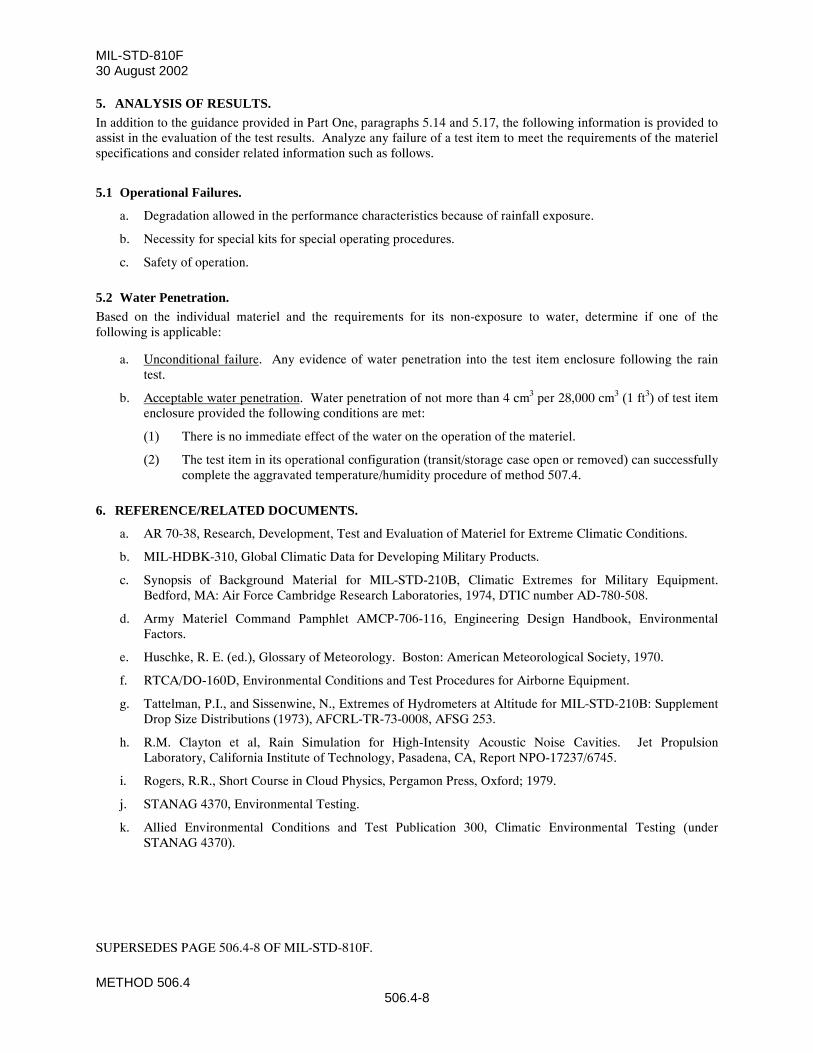
MIL-STD-810F30 August 2002
METHOD 506.4506.4-8
5. ANALYSIS OF RESULTS.In addition to the guidance provided in Part One, paragraphs 5.14 and 5.17, the following information is provided toassist in the evaluation of the test results. Analyze any failure of a test item to meet the requirements of the materielspecifications and consider related information such as follows.
5.1 Operational Failures.
a. Degradation allowed in the performance characteristics because of rainfall exposure.
b. Necessity for special kits for special operating procedures.
c. Safety of operation.
5.2 Water Penetration.Based on the individual materiel and the requirements for its non-exposure to water, determine if one of thefollowing is applicable:
a. Unconditional failure. Any evidence of water penetration into the test item enclosure following the raintest.
b. Acceptable water penetration. Water penetration of not more than 4 cm3 per 28,000 cm3 (1 ft3) of test itemenclosure provided the following conditions are met:
(1) There is no immediate effect of the water on the operation of the materiel.
(2) The test item in its operational configuration (transit/storage case open or removed) can successfullycomplete the aggravated temperature/humidity procedure of method 507.4.
6. REFERENCE/RELATED DOCUMENTS.
a. AR 70-38, Research, Development, Test and Evaluation of Materiel for Extreme Climatic Conditions.
b. MIL-HDBK-310, Global Climatic Data for Developing Military Products.
c. Synopsis of Background Material for MIL-STD-210B, Climatic Extremes for Military Equipment.Bedford, MA: Air Force Cambridge Research Laboratories, 1974, DTIC number AD-780-508.
d. Army Materiel Command Pamphlet AMCP-706-116, Engineering Design Handbook, EnvironmentalFactors.
e. Huschke, R. E. (ed.), Glossary of Meteorology. Boston: American Meteorological Society, 1970.
f. RTCA/DO-160D, Environmental Conditions and Test Procedures for Airborne Equipment.
g. Tattelman, P.I., and Sissenwine, N., Extremes of Hydrometers at Altitude for MIL-STD-210B: SupplementDrop Size Distributions (1973), AFCRL-TR-73-0008, AFSG 253.
h. R.M. Clayton et al, Rain Simulation for High-Intensity Acoustic Noise Cavities. Jet PropulsionLaboratory, California Institute of Technology, Pasadena, CA, Report NPO-17237/6745.
i. Rogers, R.R., Short Course in Cloud Physics, Pergamon Press, Oxford; 1979.
j. STANAG 4370, Environmental Testing.
k. Allied Environmental Conditions and Test Publication 300, Climatic Environmental Testing (underSTANAG 4370).
SUPERSEDES PAGE 506.4-8 OF MIL-STD-810F.
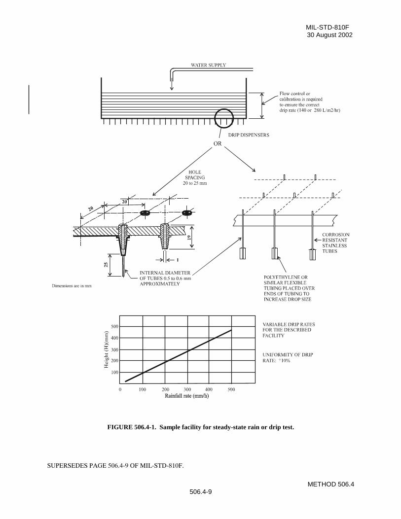
MIL-STD-810F30 August 2002
METHOD 506.4506.4-9
FIGURE 506.4-1. Sample facility for steady-state rain or drip test.
SUPERSEDES PAGE 506.4-9 OF MIL-STD-810F.
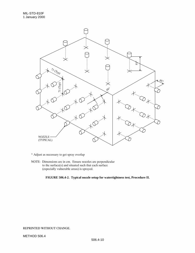
MIL-STD-810F1 January 2000
METHOD 506.4506.4-10
FIGURE 506.4-2. Typical nozzle setup for watertightness test, Procedure II.
REPRINTED WITHOUT CHANGE.
81*
71 (Typ)
71 (
Typ)
48*
48*
NOZZLE(TYPICAL)
* Adjust as necessary to get spray overlap
NOTE: Dimensions are in cm. Ensure nozzles are perpendicular to the surface(s) and situated such that each surface (especially vulnerable areas) is sprayed.
MIL-STD-810F30 August 2002
METHOD 507.4507.4-1
METHOD 507.4
HUMIDITY
NOTE: Tailoring is essential. Select methods, procedures, and parameter levels based on the tailoring processdescribed in Part One, paragraph 4.2.2, and Appendix C. Apply the general guidelines for laboratory test methodsdescribed in Part One, paragraph 5 of this standard.
1. SCOPE.
1.1 Purpose.The purpose of this method is to determine the resistance of materiel to the effects of a warm, humid atmosphere.
1.2 Application.This method applies to materiel that is likely to be stored or deployed in a warm, humid environment; anenvironment in which high levels of humidity occur; or to provide an indication of potential problems associatedwith humidity. Although it is preferable to test materiel at appropriate natural environment sites, it is not alwayspractical because of logistical, cost, or schedule considerations. Warm, humid conditions can occur year-round intropical areas, seasonally in mid-latitude areas, and in materiel subjected to combinations of changes in pressure,temperature, and relative humidity. Other high levels of humidity can exist worldwide. Further information on hightemperatures and humidity is provided in AR 70-38 or NATO STANAG 2895.
1.3 Limitations.This method may not reproduce all of the humidity effects associated with the natural environment such as long-term effects, nor with low humidity situations. This method does not attempt to duplicate the complextemperature/humidity environment but, rather, it provides a generally stressful situation that is intended to revealpotential problem areas in the materiel. Therefore, this method does not contain natural or inducedtemperature/humidity cycles as in previous editions. Specifically, this method does not address:
a. Condensation resulting from changes of pressure and temperature for airborne or ground materiel.
b. Condensation resulting from black-body radiation (e.g., night sky effects).
c. Synergistic effects of humidity or condensation combined with biological and chemical contaminants.
d. Liquid water trapped within materiel or packages and retained for significant periods.
e. This method is not intended for evaluating the internal elements of a hermetically sealed assembly sincesuch materiel is air-tight.
2. TAILORING GUIDANCE
2.1 Selecting the Humidity Method.After examining requirements documents and applying the tailoring process in Part One of this standard todetermine if warm temperature/humidity conditions are anticipated in the life cycle of materiel, use the following toconfirm the need for this method and to place it in sequence with other methods.
2.1.1 Effects of warm, humid environments.Humidity has physical and chemical effects on materiel; the temperature and humidity variations can also triggercondensation inside materiel. Consider the following typical problems to help determine if this method isappropriate for the materiel being tested. This list is not intended to be all-inclusive.
a. Surface effects, such as:
SUPERSEDES PAGE 507.4-1 OF MIL-STD-810F.
MIL-STD-810F30 August 2002
METHOD 507.4507.4-2
(1) Oxidation and/or galvanic corrosion of metals.
(2) Increased chemical reactions.
(3) Chemical or electrochemical breakdown of organic and inorganic surface coatings.
(4) Interaction of surface moisture with deposits from external sources to produce a corrosive film.
(5) Changes in friction coefficients, resulting in binding or sticking.
b. Changes in material properties, such as:
(1) Swelling of materials due to sorption effects.
(2) Other changes in properties.
(a) Loss of physical strength.
(b) Electrical and thermal insulating characteristics.
(c) Delamination of composite materials.
(d) Change in elasticity or plasticity.
(e) Degradation of hygroscopic materials.
(f) Degradation of explosives and propellants by absorption.
(g) Degradation of optical element image transmission quality.
(h) Degradation of lubricants.
c. Condensation and free water, such as:
(1) Electrical short circuits.
(2) Fogging of optical surfaces.
(3) Changes in thermal transfer characteristics.
2.1.2 Sequence among other methods.a. General. See Part One, paragraph 5.5.
b. Unique to this method. Humidity testing may produce irreversible effects. If these effects couldunrealistically influence the results of subsequent tests on the same item(s), perform humidity testingfollowing those tests. Also, because of the potentially unrepresentative combination of environmentaleffects, it is generally inappropriate to conduct this test on the same test sample that has previously beensubjected to salt fog, sand and dust, or fungus tests.
2.2 Selecting Procedure Variations.This method has one procedure. Possible variations are described below.
2.2.1 Test duration.The minimum number of 48-hour cycles for the test is five. This has historically proven adequate to reveal potentialeffects in most materiel. Extend the test as specified in the test plan to provide a higher degree of confidence in themateriel to withstand warm, humid conditions.
2.2.2 Temperature/humidity levels.Although the combined 60°C and 95% RH does not occur in nature, this combination of temperature and relativehumidity has historically provided an indication of potential problem areas in materiel.
SUPERSEDES PAGE 507.4-2 OF MIL-STD-810F.
MIL-STD-810F1 January 2000
METHOD 507.4507.4-5
air envelope surrounding the test item by methods that do not change the chemical composition of the air, water, orwater vapor within that volume of air.
4.2 Controls.a. Ensure the test chamber includes an appropriate measurement and recording device(s), separate from
the chamber controllers.
b. Test parameters. Unless otherwise specified, make continuous analog temperature and relativehumidity measurements during the test. Conduct digital measurements at intervals of 15 minutes orless.
c. Capabilities. Use only instrumentation with the selected test chamber that meets the accuracies,tolerances, etc., of Part One, paragraph 5.3.
4.3 Test Interruption.a. General. See Part One, paragraph 5.11, of this standard.
b. Specific to this method.
(1) Undertest interruption. If an unscheduled interruption occurs that causes the test conditions to fallbelow allowable limits, the test must be reinitiated at the end of the last successfully completedcycle.
(2) Overtest interruptions. If the test item(s) is exposed to test conditions that exceed allowable limits,conduct an appropriate physical examination of the test item and perform an operational check(when practical) before testing is resumed. This is especially true where a safety condition couldexist, such as with munitions. If a safety condition is discovered, the preferable course of action is toterminate the test and reinitiate testing with a new test item. If this is not done and test item failureoccurs during the remainder of the test, the test results may be considered invalid. If no problem hasbeen encountered, reestablish pre-interruption conditions and continue from the point where the testtolerances were exceeded.
4.4 Test Setup.a. General. See Part One, paragraph 5.8.
b. Unique to this method. Verify that environmental monitoring and measurement sensors are of anappropriate type and properly located to obtain the required test data.
4.5 Test Execution.The following steps, alone or in combination, provide the basis for collecting necessary information concerning thetest item in a warm, humid environment.
4.5.1 Preparation for test
4.5.1.1 Preliminary steps.Before starting the test, determine the test details (e.g., procedure variations, test item configuration, cycles,durations, parameter levels for storage/operation, etc.) from the test plan.
4.5.1.2 Pretest standard ambient checkout.All items require a pretest checkout at room ambient conditions to provide baseline data. Conduct the checkout asfollows:
Step 1. Install the test item into the test chamber and conduct an operational checkout (if appropriate) inaccordance with the test plan.
REPRINTED WITHOUT CHANGE.
MIL-STD-810F30 August 2002
METHOD 507.4507.4-6
Step 2. Prepare the test item in its required configuration in accordance with Part One, paragraph 5.8.1.Step 3. Conduct a thorough visual examination of the test item to look for conditions that could
compromise subsequent test results.Step 4. Document any significant results.Step 5. Conduct an operational checkout (if appropriate) in accordance with the test plan, and record
results.
4.5.2 Procedure.This test consists of a 24-hour conditioning period (to ensure all items at any intended climatic test location will startwith the same conditions), followed by a 24-hour temperature and humidity cycle for the number of cycles specifiedin the test plan.
Step 1. With the test item installed in the test chamber in its required configuration, adjust the temperatureto 23 ±2°C and 50 ±5% RH, and maintain for 24 hours.
Step 2. Adjust the chamber temperature to 30°C and the RH to 95%.Step 3. Expose the test item(s) to the appropriate number of test cycles (figure 507.4-1) as determined in
paragraph 2.2.1. Recommend test item performance checks (for the minimum time required toverify performance) be conducted near the end of the fifth and tenth cycles, or as otherwisespecified in the test plan, during the periods shown, and results be documented.
Step 4. At the end of the required number of cycles, adjust the temperature and humidity conditions tostandard ambient conditions.
Step 5. In order to prevent unrealistic drying, within 15 minutes after Step 3 is completed, conduct anoperational performance check, if applicable, and document the results. If the check cannot becompleted within 30 minutes, recondition the test item at 30°C and 95% RH for one hour, andthen continue the checkout.
Step 6. Perform a thorough visual examination of the test item and document any conditions resultingfrom humidity exposure.
5. ANALYSIS OF RESULTS.In addition to the guidance provided in Part One, paragraphs 5.14 and 5.17, the following information is provided toassist in the evaluation of the test results.
a. Allowable or acceptable degradation in operating characteristics.
b. Possible contributions from special operating procedures or special test provisions needed to performtesting.
c. Whether it is appropriate to separate temperature effects from humidity effects.
6. REFERENCE/RELATED DOCUMENTS.a. AR 70-38, Research, Development, Test and Evaluation of Materiel for Extreme Climatic Conditions.
b. MIL-HDBK-310, Global Climatic Data for Developing Military Products.
c. Synopsis of Background Material for MIL-STD-210B, Climatic Extremes for Military Equipment,Bedford, MA: Air Force Cambridge Research Laboratories, 24 January 1974. DTIC numberAD-780-508.
d. STANAG 2895, Climatic Environmental Conditions Affecting the Design of Materiel for Use of NATOForces.
SUPERSEDES PAGE 507.4-6 OF MIL-STD-810F.
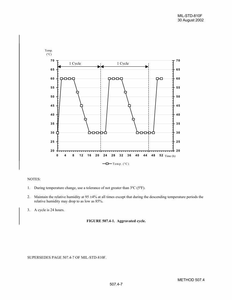
MIL-STD-810F30 August 2002
METHOD 507.4507.4-7
20
25
30
35
40
45
50
55
60
65
70
0 4 8 12 16 20 24 28 32 36 40 44 48 5220
25
30
35
40
45
50
55
60
65
70
Tem p. (°C )
NOTES:
1. During temperature change, use a tolerance of not greater than 3ºC (5ºF).
2. Maintain the relative humidity at 95 ±4% at all times except that during the descending temperature periods therelative humidity may drop to as low as 85%.
3. A cycle is 24 hours.
FIGURE 507.4-1. Aggravated cycle.
SUPERSEDES PAGE 507.4-7 OF MIL-STD-810F.
Temp. (°C)
Time (h)
1 Cycle 1 Cycle

MIL-STD-810F1 January 2000
METHOD 507.4507.4-8
THIS PAGE INTENTIONALLY BLANK
REPRINTED WITHOUT CHANGE.
MIL-STD-810F30 August 2002
METHOD 508.5508.5-1
METHOD 508.5
FUNGUS
NOTE: Tailoring is essential. Select methods, procedures and parameter levels based on the tailoring processdescribed in Part One, paragraph 4, and Appendix C. Apply the general guidelines for laboratory test methodsdescribed in Part One, paragraph 5 of this standard.
1. SCOPE.
1.1 Purpose.The purpose of this fungus test is to assess the extent to which materiel will support fungal growth and how anyfungal growth may affect performance or use of the materiel. The primary objectives of the fungus test are todetermine:
a. if the materials comprising the materiel, or the assembled combination of same, will support fungal growth,and if so, of what species.
b. how rapidly fungus will grow on the materiel.
c. how fungus affects the materiel, its mission, and its safety for use following the growth of fungus on themateriel.
d. if the materiel can be stored effectively in a field environment.
e. if there are simple reversal processes, e.g., wiping off fungal growth.
1.2 Application.Since microbial deterioration is a function of temperature and humidity and is an inseparable condition of hot,humid tropics and the midlatitudes, consider it in the design of all standard, general-purpose materiel. This methodis used to determine if fungal growth will occur and, if so, how it may degrade/impact the use of the materiel.
NOTES: 1. This test procedure and the accompanying preparation and post-test analysis involve highly-specializedtechniques and potentially-hazardous organisms. Use only technically-qualified personnel (e.g.,microbiologists) to perform the test.
2. Although the basic (documented) resistance of materials to fungal growth is helpful in the design ofnew materiel; the combination of materials, the physical structure of combined materials, and the possiblecontamination of resistant materials during manufacture necessitate laboratory or natural environmenttests to verify the resistance of the assembled materiel to fungal growth.
1.3 Limitations.This test is designed to obtain data on the susceptibility of materiel. Do not use it for testing of basic materials sincevarious other test procedures, including soil burial, pure culture, mixed culture, and plate testing are available.
2. TAILORING GUIDANCE.
2.1 Selecting the Fungus Method.After examining requirements documents and applying the tailoring process in Part One of this standard todetermine where fungal growth is anticipated in the life cycle of materiel, use the following to confirm the need forthis method and to place it in sequence with other methods.
2.1.1 Effects of fungus growth.Fungal growth impairs the functioning or use of materiel by changing its physical properties.
SUPERSEDES PAGE 508.5-1 OF MIL-STD-810F.
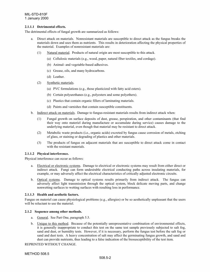
MIL-STD-810F1 January 2000
METHOD 508.5508.5-2
2.1.1.1 Detrimental effects.The detrimental effects of fungal growth are summarized as follows:
a. Direct attack on materials. Nonresistant materials are susceptible to direct attack as the fungus breaks thematerials down and uses them as nutrients. This results in deterioration affecting the physical properties ofthe material. Examples of nonresistant materials are:
(1) Natural material. Products of natural origin are most susceptible to this attack.
(a) Cellulosic materials (e.g., wood, paper, natural fiber textiles, and cordage).
(b) Animal- and vegetable-based adhesives.
(c) Grease, oils, and many hydrocarbons.
(d) Leather.
(2) Synthetic materials.
(a) PVC formulations (e.g., those plasticized with fatty acid esters).
(b) Certain polyurethanes (e.g., polyesters and some polyethers).
(c) Plastics that contain organic fillers of laminating materials.
(d) Paints and varnishes that contain susceptible constituents.
b. Indirect attack on materials. Damage to fungus-resistant materials results from indirect attack when:
(1) Fungal growth on surface deposits of dust, grease, perspiration, and other contaminants (that findtheir way onto materiel during manufacture or accumulate during service) causes damage to theunderlying material, even though that material may be resistant to direct attack.
(2) Metabolic waste products (i.e., organic acids) excreted by fungus cause corrosion of metals, etchingof glass, or staining or degrading of plastics and other materials.
(3) The products of fungus on adjacent materials that are susceptible to direct attack come in contactwith the resistant materials.
2.1.1.2 Physical interference.Physical interference can occur as follows:
a. Electrical or electronic systems. Damage to electrical or electronic systems may result from either direct orindirect attack. Fungi can form undesirable electrical conducting paths across insulating materials, forexample, or may adversely affect the electrical characteristics of critically adjusted electronic circuits.
b. Optical systems. Damage to optical systems results primarily from indirect attack. The fungus canadversely affect light transmission through the optical system, block delicate moving parts, and changenonwetting surfaces to wetting surfaces with resulting loss in performance.
2.1.1.3 Health and aesthetic factors.Fungus on materiel can cause physiological problems (e.g., allergies) or be so aesthetically unpleasant that the userswill be reluctant to use the materiel.
2.1.2 Sequence among other methods.
a. General. See Part One, paragraph 5.5.
b. Unique to this method. Because of the potentially unrepresentative combination of environmental effects,it is generally inappropriate to conduct this test on the same test sample previously subjected to salt fog,sand and dust, or humidity tests. However, if it is necessary, perform the fungus test before the salt fog orsand and dust tests. A heavy concentration of salt may affect the germinating fungus growth, and sand anddust can provide nutrients, thus leading to a false indication of the biosusceptibility of the test item.
REPRINTED WITHOUT CHANGE.
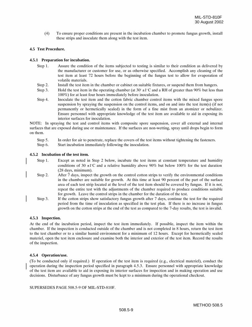
MIL-STD-810F30 August 2002
METHOD 508.5508.5-9
(4) To ensure proper conditions are present in the incubation chamber to promote fungus growth, installthese strips and inoculate them along with the test item.
4.5 Test Procedure.
4.5.1 Preparation for incubation.Step 1. Assure the condition of the items subjected to testing is similar to their condition as delivered by
the manufacturer or customer for use, or as otherwise specified. Accomplish any cleaning of thetest item at least 72 hours before the beginning of the fungus test to allow for evaporation ofvolatile materials.
Step 2. Install the test item in the chamber or cabinet on suitable fixtures, or suspend them from hangers.Step 3. Hold the test item in the operating chamber (at 30o ±1o
C and a RH of greater than 90% but less than100%) for at least four hours immediately before inoculation.
Step 4. Inoculate the test item and the cotton fabric chamber control items with the mixed fungus sporesuspension by spraying the suspension on the control items, and on and into the test item(s) (if notpermanently or hermetically sealed) in the form of a fine mist from an atomizer or nebulizer.Ensure personnel with appropriate knowledge of the test item are available to aid in exposing itsinterior surfaces for inoculation.
NOTE: In spraying the test and control items with composite spore suspension, cover all external and internalsurfaces that are exposed during use or maintenance. If the surfaces are non-wetting, spray until drops begin to formon them.
Step 5. In order for air to penetrate, replace the covers of the test items without tightening the fasteners.Step 6. Start incubation immediately following the inoculation.
4.5.2 Incubation of the test item.Step 1. Except as noted in Step 2 below, incubate the test items at constant temperature and humidity
conditions of 30 ±1oC and a relative humidity above 90% but below 100% for the test duration(28 days, minimum).
Step 2. After 7 days, inspect the growth on the control cotton strips to verify the environmental conditionsin the chamber are suitable for growth. At this time at least 90 percent of the part of the surfacearea of each test strip located at the level of the test item should be covered by fungus. If it is not,repeat the entire test with the adjustments of the chamber required to produce conditions suitablefor growth. Leave the control strips in the chamber for the duration of the test.
Step 3. If the cotton strips show satisfactory fungus growth after 7 days, continue the test for the requiredperiod from the time of inoculation as specified in the test plan. If there is no increase in fungusgrowth on the cotton strips at the end of the test as compared to the 7-day results, the test is invalid.
4.5.3 Inspection.At the end of the incubation period, inspect the test item immediately. If possible, inspect the item within thechamber. If the inspection is conducted outside of the chamber and is not completed in 8 hours, return the test itemto the test chamber or to a similar humid environment for a minimum of 12 hours. Except for hermetically sealedmateriel, open the test item enclosure and examine both the interior and exterior of the test item. Record the resultsof the inspection.
4.5.4 Operation/use.(To be conducted only if required.) If operation of the test item is required (e.g., electrical materiel), conduct theoperation during the inspection period specified in paragraph 4.5.3. Ensure personnel with appropriate knowledgeof the test item are available to aid in exposing its interior surfaces for inspection and in making operation and usedecisions. Disturbance of any fungus growth must be kept to a minimum during the operational checkout.
SUPERSEDES PAGE 508.5-9 OF MIL-STD-810F.
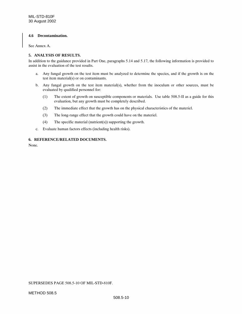
MIL-STD-810F30 August 2002
METHOD 508.5508.5-10
4.6 Decontamination.
See Annex A.
5. ANALYSIS OF RESULTS.In addition to the guidance provided in Part One, paragraphs 5.14 and 5.17, the following information is provided toassist in the evaluation of the test results.
a. Any fungal growth on the test item must be analyzed to determine the species, and if the growth is on thetest item material(s) or on contaminants.
b. Any fungal growth on the test item material(s), whether from the inoculum or other sources, must beevaluated by qualified personnel for:
(1) The extent of growth on susceptible components or materials. Use table 508.5-II as a guide for thisevaluation, but any growth must be completely described.
(2) The immediate effect that the growth has on the physical characteristics of the materiel.
(3) The long-range effect that the growth could have on the materiel.
(4) The specific material (nutrient(s)) supporting the growth.
c. Evaluate human factors effects (including health risks).
6. REFERENCE/RELATED DOCUMENTS.None.
SUPERSEDES PAGE 508.5-10 OF MIL-STD-810F.
MIL-STD-810F30 August 2002ANNEX A
METHOD 508.5508.5A-1
ANNEX A
Decontamination of Test Equipment and Test ItemsAfter Exposure to Fungus
1. Decontamination of test equipment, materials, and test items that have been subjected to a fungus test isparamount when the test items are to be sent back to the users, manufacturer, or material management office forfurther evaluation or reuse. Many test items are too expensive to scrap and must be decontaminated.
a. Decontamination and disinfection of the test chamber
(1) Initially, good housekeeping procedures should be followed for all testing, especially those testsinvolving live cultures.
(2) Prior to any testing, the climatic chamber should be thoroughly cleaned inside with a hot, soapywater (or Lysol®-type cleaner) solution.
(3) With no items in chamber, high heat (at least 60°C/140°F) is applied for at least 2 hours (nohumidity required). Cool the chamber to ambient prior to placing the test items in the chamber forfungus testing.
(4) After testing is complete and the items have been examined/pictures taken, the items and thechamber can be initially sterilized with high heat as above and at least 90% relative humidity for atleast 2 hours. The humidity keeps the surfaces wet until the spores are destroyed. (NOTE: Theitems must be able to withstand the high temperature chosen for initial sterilization without damage.Check the test item user's manual for the storage temperature before proceeding). After heatsterilization, the chamber can be washed with a sodium or calcium hypochlorite solution at5000 ppm concentration (wear appropriate personal protective equipment [PPE] when using anychemical solutions). A phenolic disinfectant spray can also be used. Copious flushing with water torinse the chamber is needed to limit the chlorine contact on the metals surfaces.
(5) If the test items are washable, follow the instructions for each item and launder in a machine, ifpossible.
(6) If the items cannot be washed with a solution, wipe with a damp cloth that has been sprayed with aphenolic solution (disinfectant spray) and label the items appropriately with precautions on handlingitems which have been subjected to fungus testing. Personnel trained in microbiological techniquesand who conduct these tests should have general operating procedures in place for handling funguscultures and test items after exposure.
NEW PAGE
MIL-STD-810F30 August 2002ANNEX A
METHOD 508.5508.5A-2
THIS PAGE INTENTIONALLY BLANK
NEW PAGE
MIL-STD-810F30 August 2002
METHOD 509.4509.4-3
b. Outside of its shipping/storage container but provided with an effective environmental control systemthat partly excludes the salt fog environment.
c. Outside of its shipping/storage container and set up in its normal operating mode.
d. Modified with kits for special applications or to compensate for mating components that are normallypresent, but are not used for this specific test.
2.2.3 Duration.The standard exposure of 48 hours of exposure and 48 hours of drying time has not changed. However, experiencehas shown that alternating 24-hour periods of salt fog exposure and drying conditions for a minimum of four 24-hour periods (two wet and two dry), provides more realistic exposure and a higher damage potential than doescontinuous exposure to a salt atmosphere (reference d.). Because the rate of corrosion is much higher during thetransition from wet to dry, it is critical to control the rate of drying closely if corrosion levels from test to test are tobe compared. Dry the test items for 24 hours. Increase the number of cycles to provide a higher degree of confidencein the ability of the materials involved to withstand a corrosive environment.
2.2.4 Temperature.Maintain the temperature in the exposure zone at 35 ±2°C (95 ±4°F). This temperature has been historicallyaccepted and is not intended to simulate actual exposure situations. Other temperatures may be used if appropriate.
2.2.5 Air circulation.Ensure the air velocity in test chambers is minimal (essentially zero).
2.2.6 Fallout rate.Adjust the salt fog fallout such that each receptacle collects from 1 to 3 ml of solution per hour for each 80 cm2 ofhorizontal collecting area (10 cm diameter).
3. INFORMATION REQUIRED.
3.1 Pretest.The following information is required to conduct salt fog tests adequately.
a. General. Information listed in Part One, paragraphs 5.7 and 5.9, and Appendix A, Task 405 of thisstandard.
b. Specific to this method.
(1) Areas of the test item visually and functionally examined and an explanation of their inclusion orexclusion.
(2) Salt concentration if other than 5%.
(3) Resistivity of initial water and type of water.
3.2 During Test.Collect the following information during conduct of the test:
a. General. Information listed in Part One, paragraph 5.10, and in Appendix A, Task 406 of this standard.
b. Specific to this method.
(1) Record of chamber temperature versus time conditions.
(2) Salt fog fallout quantities per unit of time (paragraph 4.1.4).
(3) Salt fog pH (paragraph 4.5.1.1b).
SUPERSEDES PAGE 509.4-3 OF MIL-STD-810F.
MIL-STD-810F1 January 2000
METHOD 509.4509.4-4
3.3 Post Test.The following post test information is required.
a. General. Information listed in Part One, paragraph 5.13, and in Appendix A, Task 406 of this standard.
b. Specific to this method.
(1) Areas of the test item visually and functionally examined and an explanation of their inclusion orexclusion.
(2) Test variables:
(a) Salt solution pH.
(b) Salt solution fallout rate (ml/cm2/hr).
(3) Results of examination for corrosion, electrical, and physical effects.
(4) Observations to aid in failure analysis.
4. TEST PROCESS.
4.1 Test Facility.Ensure the apparatus used in performing the salt fog test includes the following.
4.1.1 Test chamber.Use supporting racks that do not affect the characteristics of the salt fog mist. All parts of the test setup that contactthe test item must not cause electrolytic corrosion. Do not allow condensation to drip on the test item. Do not returnto the salt solution reservoir any liquid that comes in contact with either the chamber or the test item. Vent theexposure area to prevent pressure buildup. Ensure the test chamber has a waste collection system so that all wastematerial can be tested prior to disposal. Dispose of any material determined to be hazardous waste in accordancewith local, state and federal regulations.
4.1.2 Salt solution reservoir.Ensure the salt solution reservoir is made of material that is non-reactive with the salt solution, e.g., glass, hardrubber, or plastic.
4.1.3 Salt solution injection system.Filter the salt solution (figures 509.4-2 and -3) and inject it into the test chamber with atomizers that produce a finelydivided, wet, dense fog. Use atomizing nozzles and a piping system made of material that is non-reactive to the saltsolution. Do not let salt buildup clog the nozzles.
NOTE: Suitable atomization has been obtained in chambers having a volume of less than .34m3 (12 ft3) under thefollowing conditions:
a. Nozzle pressure as low as practical to produce fog at the required rate.
b. Orifices between 0.5 and 0.76 mm (0.02 and 0.03 in) in diameter.
c. Atomization of approximately 2.8 liters of salt solution per 0.28m3 (10 ft3) of chamber volume per24 hours.
When chambers with a volume considerably in excess of 0.34m3 (12 ft3) are used, the conditions specified may requiremodification.
4.1.4 Salt fog collection receptacles.Use a minimum of 2 salt fog collection receptacles to collect water solution samples. Locate one at the perimeter ofthe test item nearest to the nozzle, and the other also at the perimeter of the test item but at the farthest point from the
REPRINTED WITHOUT CHANGE.
MIL-STD-810F30 August 2002
METHOD 509.4509.4-5
nozzle. If using multiple nozzles, the same principles apply. Position the receptacles such that they are not shieldedby the test item and will not collect drops of solution from the test item or other sources.
4.2 Controls.Preheat the oil-free and dirt-free compressed air used to produce the atomized solution (to offset the cooling effectsof expansion to atmospheric pressure) (see table 509.4-I).
TABLE 509.4-I. Air pressure and preheat temperature requirements for operation at 35oC.
Air Pressure (kPa) 83 96 110 124
Preheat temperature (oC) (before atomizing)
46 47 48 49
4.3 Test Interruption.a. General. See Part One, paragraph 5.11, of this standard.
b. Specific to this method.
(1) Undertest interruption. If an unscheduled test interruption occurs that causes the test conditions toexceed allowable tolerances toward standard ambient conditions, give the test item a completevisual examination and develop a technical evaluation of the impact of the interruption on the testresults. Restart the test at the point of interruption and restabilize the test item at the test conditions.
(2) Overtest interruption. If an unscheduled test interruption occurs that causes the test conditions toexceed allowable tolerances away from standard ambient conditions, stabilize the test conditions towithin tolerances and hold them at that level until a complete visual examination and technicalevaluation can be made to determine the impact of the interruption on test results. If the visualexamination or technical evaluation results in a conclusion that the test interruption did notadversely affect the final test results, or if the effects of the interruption can be nullified withconfidence, restabilize the pre-interruption conditions and continue the test from the point where thetest tolerances were exceeded.
4.4 Test Setup.a. General. See Part One, paragraph 5.8.
b. Unique to this method. Ensure the fallout collection containers are situated in the chamber such thatthey will not collect fluids dripping from the test item.
4.5 Test Execution.The following steps, alone or in combination, provide the basis for collecting necessary information concerning thetest item in a salt fog environment.
4.5.1 Preparation for test.
4.5.1.1 Preliminary steps.Before starting the test, determine the test details (e.g., procedure variations, test item configuration, cycles,durations, parameter levels for storage/operation, etc.) from the test plan. (See paragraph 3.1, above.)
a. Handling and configuration.
(1) Handle the test item as little as possible. Prepare the test item for testing immediately beforeexposure. Unless otherwise specified, ensure the test item surfaces are free of surface contaminationsuch as oil, grease, or dirt that could cause a water break. Do not use corrosive solvents, solventswhich deposit either corrosive or protective films, or abrasives other than a paste of pure magnesiumoxide in any cleaning methods.
SUPERSEDES PAGE 509.4-5 OF MIL-STD-810F.
MIL-STD-810F30 August 2002
METHOD 509.4509.4-6
(2) Configure the test item as specified in the test plan and insert it into the test chamber.
b. Preparation of salt solution. For this test, use sodium chloride containing (on a dry basis) not more than0.1% sodium iodide and not more than 0.5% total impurities. Do not use sodium chloride containinganti-caking agents because such agents may act as corrosion inhibitors. Unless otherwise specified,prepare a 5 ±1% solution by dissolving 5 parts by weight of salt in 95 parts by weight of water. Adjust toand maintain the solution at a specific gravity (figure 509.4-1) by using the measured temperature anddensity of the salt solution. If necessary, add sodium tetraborate (borax) to the salt solution as a pHstabilization agent in a ratio not to exceed 0.7g sodium tetraborate to 75 liters of salt solution. Maintainthe pH of the salt solution, as collected as fallout in the exposure chamber, between 6.5 and 7.2 with thesolution temperature at +35 ±2°C. To adjust the pH, use only diluted chemically pure hydrochloric acidor chemically pure sodium hydroxide. Make the pH measurement either electrometrically orcalorimetrically.
c. Chamber operation verification. Unless the chamber has been used within five days or the nozzlebecomes clogged, immediately before the test and with the exposure chamber empty, adjust all testparameters to those required for the test. Maintain these conditions for at least one 24-hour period oruntil proper operation and salt fog collection can be verified. To verify the chamber is operatingproperly, measure the salt fog fallout after 24 hours, but monitor and record the test chamber temperatureimmediately prior to testing, and at least every two hours thereafter.
4.5.1.2 Pretest standard ambient checkout.All items require a pretest checkout at room ambient conditions to provide baseline data. Conduct the checkout asfollows:
Step 1. Prepare the test item in its required configuration in accordance with Part One, paragraph 5.8.1.Step 2. Record the room ambient conditions.Step 3. Conduct a complete visual examination of the test item with attention to:
(1) High-stress areas.(2) Areas where dissimilar metals are in contact.(3) Electrical and electronic components - especially those having closely spaced, unpainted or
exposed circuitry.(4) Metallic surfaces.(5) Enclosed volumes where condensation has occurred or may occur.(6) Components or surfaces provided with coatings or surface treatments for corrosion protection.(7) Cathodic protection systems; mechanical systems subject to malfunction if clogged or coated
with salt deposits.(8) Electrical and thermal insulators.
NOTE: Consider partial or complete disassembly of the test item if a complete visual examination is required. Becareful not to damage any protective coatings, etc.
Step 4. Document the results. (Use photographs, if necessary.)Step 5. Conduct an operational checkout in accordance with the test plan and record the results for
compliance with Part One, paragraph 5.9.Step 6. If the test item meets the requirements of the test plan or other applicable documents, proceed to
Step 1 of the test procedure below. If not, resolve any problems and restart the pretest standardambient checkout at the most reasonable step above.
4.5.2 Procedure.Step 1. Adjust the test chamber temperature to 35°C and condition the test item for at least two hours
before introducing the salt fog.
SUPERSEDES PAGE 509.4-6 OF MIL-STD-810F.
MIL-STD-810F30 August 2002
METHOD 509.4509.4-7
Step 2. Continuously atomize a salt solution of a composition as given in paragraph 4.5.1.1b into the testchamber for a period of 24 hours or as specified in the test plan. During the entire exposure periodmeasure the salt fog fallout rate and pH of the fallout solution at least at 24-hour intervals1/.Ensure the fallout is between 1 and 3 ml/80cm2/hr.
Step 3. Dry the test item at standard ambient temperatures and a relative humidity of 50% + 5% for24 hours. Minimize handling the test item or adjusting any mechanical features during the dryingperiod.
Step 4. At the end of the drying period and unless otherwise specified, replace the test item in the salt fogchamber and repeat steps 2 and 3.
Step 5. Visually inspect the test item in accordance with the guidelines given in paragraph 4.5.1.2.Step 6. After completing the physical and electrical checkout, document the results (with photographs, if
necessary). Then, if necessary to aid in a follow-on corrosion examination, use a gentle wash inrunning water, which is at standard ambient conditions, conduct the corrosion examination, anddocument the results.
5. ANALYSIS OF RESULTS.In addition to the guidance provided in Part One, paragraphs 5.14 and 5.17, the following information is provided toassist in the evaluation of the test results.
a. Physical. Salt deposits can cause clogging or binding of mechanical components and assemblies. Theextent of any deposits resulting from this test may be representative of those induced by anticipatedenvironments.
b. Electrical. Moisture remaining after the 24-hour drying period could cause electrical malfunctions. Ifso, attempt to relate the malfunctions to that possible in service.
c. Corrosion. Analyze any corrosion for its immediate and potential long-term effects on the properfunctioning and structural integrity of the test item.
6. REFERENCE/RELATED DOCUMENTS.a. AR 70-38, Research, Development, Test and Evaluation of Materiel for Extreme Climatic Conditions.
b. MIL-HDBK-310, Global Climatic Data for Developing Military Products.
c. Army Materiel Command Pamphlet AMCP-706-116, Engineering Design Handbook, EnvironmentalFactors.
d. Final Letter Report of Methodology Investigation on Evaluation of Test Procedures Used for Salt FogTests, TECOM Project 7-CO-PB7-AP1-018, Aberdeen Proving Ground, MD 21005; July 1979.
1/ Recommend more frequent intervals. Repeat the interval if fallout quantity requirements are not met.
SUPERSEDES PAGE 509.4-7 OF MIL-STD-810F.
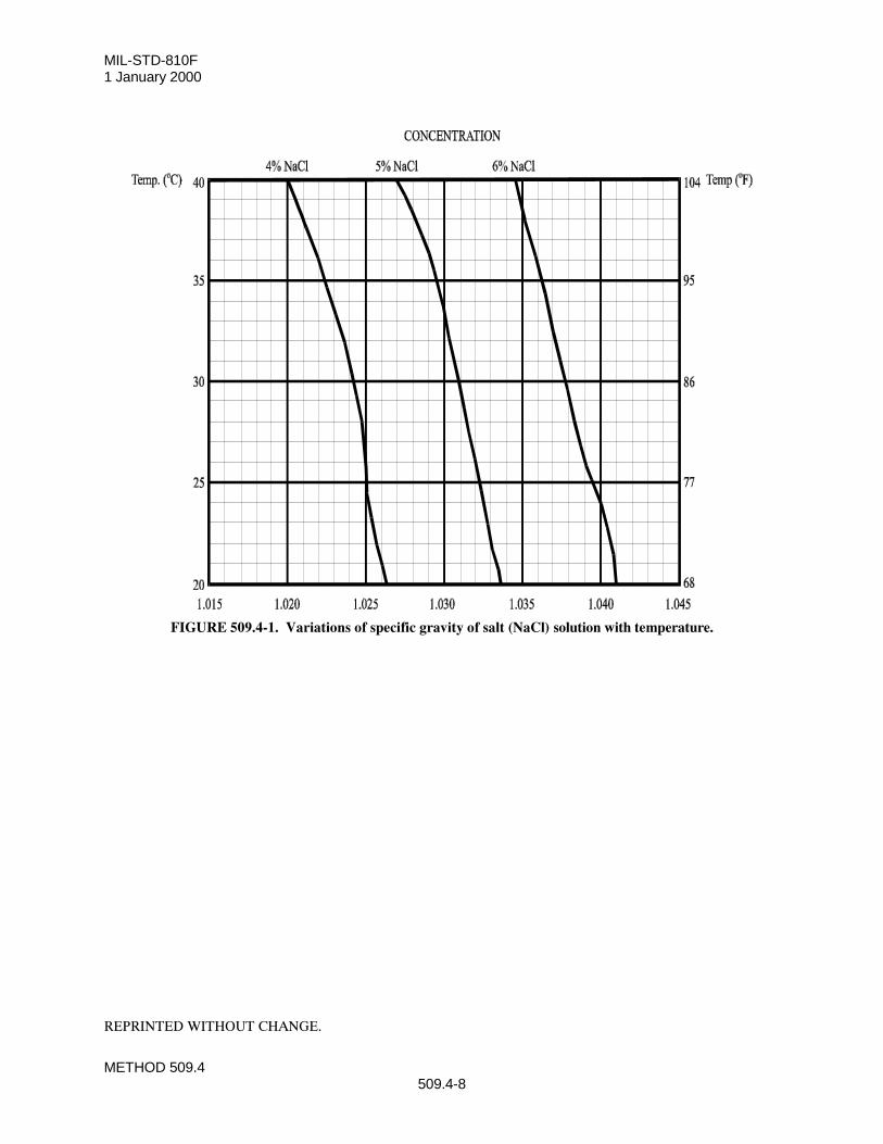
MIL-STD-810F1 January 2000
METHOD 509.4509.4-8
FIGURE 509.4-1. Variations of specific gravity of salt (NaCl) solution with temperature.
REPRINTED WITHOUT CHANGE.
MIL-STD-810F1 January 2000
METHOD 510.4510.4-9
4.4 Execution.The following steps, alone or in combination, provide the basis for collecting necessary information concerning thetest item in sand and dust environments.
4.4.1 Preparation for test.**WARNING** The relatively dry test environment combined with the moving air, organic dust, and sandparticles may cause a buildup of electrostatic energy that could affect operation of the test item. Use caution whenmaking contact with the test item during or following testing if organic dust is used, and be aware of potentialanomalies caused by electrostatic discharge during test item checkout.
4.4.1.1 Preliminary steps.Before starting the test, review pretest information in the currently approved test plan to determine test details (e.g.,procedures, item configuration, cycles, durations, parameter levels for storage/operation, etc.). (See paragraph 3.1,above.)
a. Determine from the test plan which test procedure is required.
b. Determine from the test plan specific test variables to be used.
c. Operate the test chamber without the test item to confirm proper operation.
(1) Calibrate the sand dispensing system for the sand concentration specified in the test plan.
(2) Adjust the air system or test item position to obtain the specified air velocity for the test item. Seeparagraph 4.1c(2), above.
(3) For the settling dust test, verify the fallout rate over a two-hour period using a one-minute injectionperiod each hour, followed by a 59-minute settling period.
4.4.1.2 Pretest standard ambient checkout.All items require a pretest standard ambient checkout to provide baseline data. Conduct the pretest checkout asfollows:
Step 1. Position the test item as near the center of the test chamber as possible and from any other test item(if more than one item is being tested). For the blowing sand or dust procedures, orient the testitem to expose the most critical or vulnerable parts to the sand or dust stream. For the settling dusttest, position the test to represent its normal orientation during operation or storage.
NOTE: If required by the test plan, change the orientation of the test item as specified during the test.
Step 2. Prepare the test item in its operating configuration or as specified in the test plan.Step 3. Ensure the test item is grounded (either through direct contact with the test chamber or with a
grounding strap).Step 4. Stabilize the test item temperature to standard ambient conditions.Step 5. Conduct a complete visual examination of the test item with special attention to sealed areas and
small/minute openings.Step 6. Document the results.Step 7. Conduct an operational checkout in accordance with the test plan and record results.Step 8. If the test item operates satisfactorily, proceed to step 1 of the test procedure. If not, resolve the
problem and restart at Step 1 of pretest checkout.
4.4.2 Procedure I - Blowing dust.**WARNING** Silica flour (or other dusts of similar particle size) may present a health hazard. When using silicaflour, ensure the chamber is functioning properly and not leaking; if a failure of containment is noted and personnelmight have been exposed, obtain air samples and compare them to the current threshold limit values of the nationalsafety and health regulations. Make chamber repairs and/or take other appropriate action before continuing use of
REPRINTED WITHOUT CHANGE.
MIL-STD-810F30 August 2002
METHOD 510.4510.4-10
the chamber. Be extremely careful during all steps where exposure of personnel to the silica dust is possible.Additionally, fine dust becomes potentially explosive when its concentration in air exceeds 20 g/m3.
Step 1. With the test item in the chamber, adjust the test section temperature to standard ambientconditions and the air velocity to the required value, determined from the test plan. Adjust the testsection relative humidity to less than 30% and maintain it throughout the test.
Step 2. Adjust the dust feed control for a dust concentration of 10 ± 7 g/m3.Step 3. Unless otherwise specified, maintain the conditions of Steps 1 and 2 for at least 6 hours. If
required, periodically reorient the test item to expose other vulnerable faces to the dust stream.SEE ABOVE WARNING NOTES in paragraphs 5.4 and 5.4.2.
Step 4. Stop the dust feed. Reduce the test section air velocity to approximately 1.5 m/s and adjust thetemperature to the required high operational temperature, OR as otherwise determined from the testplan.
Step 5. Maintain the step 4 conditions for 1 hour following test temperature stabilization.Step 6. Adjust the air velocity to that used in Step 1 and restart the dust feed to maintain the dust
concentration as in Step 2.Step 7. Continue the exposure for at least 6 hours or as otherwise specified. If required, operate the test
item in accordance with the test plan.Step 8. Allow the test item to return to standard ambient conditions, and the dust to settle. SEE THE
WARNING AT THE BEGINNING OF THIS PROCEDURE AND IN PARAGRAPH 4.4.1,ABOVE.
Step 9. Remove accumulated dust from the test item by brushing, wiping or shaking, taking care to avoidintroduction of additional dust or disturbing any which may have already entered the test item. Donot remove dust by either air blast or vacuum cleaning unless these methods are likely to be used inservice.
Step 10. Perform an operational check in accordance with the approved test plan, and document the resultsfor comparison with pretest data.
Step 11. Inspect the test item for dust penetration, giving special attention to bearings, grease seals,lubricants, filters, ventilation points, etc. Document the results.
4.4.3 Procedure II - Blowing sand.Step 1. Position the test item at the required distance from the sand injection point and adjust air velocity
according to test plan.Step 2. Stabilize the test item at its high operating temperature.Step 3. Adjust the sand feeder to obtain the sand mass flow rate determined from the pretest calibration.Step 4. Maintain the conditions of Steps 1 through 3 for the duration specified in the test plan. If required,
re-orient the test item at 90-minute intervals to expose all vulnerable faces to the blowing sand andrepeat Steps 1-3.
Step 5. If operation of the test item during the test is required, perform an operational test of the itemduring the last hour of the test and document the results. If not, proceed to Step 6.**SEE THE WARNING IN PARAGRAPH 4.4.2, ABOVE.**
Step 6. Allow the test item to return to standard ambient conditions. Remove accumulated sand from thetest item by using the methods anticipated to be used in service such as brushing, wiping, shaking,etc., taking care to avoid introduction of additional sand into the test item.
Step 7. Conduct an operational check of the test item in accordance with the approved test plan and recordresults for comparison with pretest data.
Step 8. Visually inspect the test item looking for abrasion and clogging effects, and any evidence of sandpenetration. Document the results.
4.4.4 Procedure III - Settling dust.**SEE THE WARNING NOTE IN PARAGRAPH 4.4.2, ABOVE.**
Step 1. With the test item and collection plates in the test chamber, adjust the test section temperature to23°C or as otherwise specified, and the relative humidity to less than 30%. (Maintain less than30% relative humidity throughout the test.)
SUPERSEDES PAGE 510.4-10 OF MIL-STD-810F.
MIL-STD-810F30 August 2002
METHOD 511.4511.4-1
METHOD 511.4
EXPLOSIVE ATMOSPHERE
NOTE: Tailoring is essential. Select methods, procedures, and parameter levels based on the tailoring processdescribed in Part One, paragraph 4.2.2; and Appendix C. Apply the general guidelines for laboratory test methodsdescribed in Part One, paragraph 5, of this standard.
1. SCOPE
1.1 Purpose. The explosive atmosphere test is performed to:
a. demonstrate the ability of materiel to operate in fuel-air explosive atmospheres without causing ignition, or
b. demonstrate that an explosive or burning reaction occurring within encased equipment will be contained,and will not propagate outside the test item.
1.2 Application. This method applies to all materiel designed for use in or near the vicinity of fuel-air explosive atmospheresassociated with aircraft, automotive, and marine fuels at or above sea level. Procedure II specifically relates toatmospheres in a space in which flammable fluids or vapors exist, or can exist, either continuously or intermittently(e.g., in fuel tanks or within fuel systems). NOTE: Materiel tested to Procedure II is designed such that ignition ofan explosive mixture is contained within the materiel without igniting the surrounding explosive atmosphere; and,during normal operation, or as a result of any fault, the temperature of any external surface will not rise to a levelcapable of causing ignition (including hermetically-sealed materiel). Use other explosive atmosphere safety tests(e.g., electrical or mine safety) if more appropriate.
1.3 Limitations. a. These procedures use an explosive mixture that has a relatively low flash point that may not be
representative of some actual fuel-air or aerosol (such as suspended dust) mixtures.
b. The explosive atmosphere test is a conservative test. If the test item does not ignite the test fuel-airmixture, there is a low probability that the materiel will ignite prevailing fuel vapor mixtures in service. Conversely, the ignition of the test fuel-air mixture by the test item does not mean the materiel will alwaysignite fuel vapors that occur in actual use.
c. These procedures are not appropriate for test altitudes above approximately 16km where the lack ofoxygen inhibits ignition.
d. Because this test is designed for electrical spark ignition, this method is not intended to demonstrateignition due to high surface temperatures.
2. TAILORING GUIDANCE
2.1 Selecting the Explosive Atmosphere Method. After examining requirements documents and applying the tailoring process in Part One of this standard todetermine where explosive atmospheres are foreseen in the life cycle of the test item, use the following to confirmthe need for this method and to place it in sequence with other methods.
2.1.1 Procedure I – Explosive Atmosphere. This procedure is applicable to all types of sealed and unsealed materiel. This test evaluates the ability of the testitem to be operated in a fuel vapor environment without igniting the environment.
SUPERSEDES PAGE 511.4-1 OF NOTICE 1 TO MIL-STD-810F.
MIL-STD-810F30 August 2002
METHOD 511.4511.4-2
2.1.2 Procedure II – Explosion Containment. This procedure is used to determine the ability of the test item's case or other enclosures to contain an explosion orflame that is a result of an internal materiel malfunction.
2.1.3 Effects of explosive atmosphere environments. Low levels of electrical energy discharge or electrical arcing by devices as simple as pocket transistor radios canignite mixtures of fuel vapor and air. A "hot spot" on the surface of the case of a hermetically sealed, apparentlyinert materiel case can ignite fuel-air mixtures. Fuel vapors in confined spaces can be ignited by a low energydischarge such as a spark from a short-circuited flashlight cell, switch contacts, electrostatic discharge, etc.
2.1.4 Sequence among other methods.a. General. See Part One, paragraph 5.5.b. Unique to this method. Considering the approach to conserve test item life by applying what are perceived
to be the least damaging environments first, generally apply explosive atmosphere tests late in the testsequence. Vibration, shock, and temperature stresses may distort seals and reduce their effectiveness, thusmaking ignition of flammable atmospheres more likely. Recommend the test item(s) first undergo theabove tests (on the same item(s)) to better approximate the actual operational environment.
2.2 Selecting procedure variations. Before conducting this test, complete the tailoring process by selecting specific procedure variations (special testconditions/techniques for this procedure) based on requirements documents, Life Cycle Environmental Profile,Operational Environment Documentation (see Part One, figure 1-1), and information provided with theseprocedures. Consider the following:
2.2.1 Fuel. Unless otherwise specified, use n-hexane as the test fuel, either reagent grade or 95% n-hexane with 5% otherhexane isomers. This fuel is used because its ignition properties in flammable atmospheres are equal to or moresensitive than the similar properties of 100/130-octane aviation gasoline, JP-4, and JP-8 jet engine fuel. Optimummixtures of n-hexane and air will ignite from hot-spot temperatures as low as 223°C, while optimum JP-4 fuel-airmixtures require a minimum temperature of 230°C for auto-ignition, and 100/130 octane aviation gasoline and airrequires 441°C for hot-spot ignition. Minimum spark energy inputs for ignition of optimum fuel vapor and airmixtures are essentially the same for n-hexane and for 100/130-octane aviation gasoline. Much higher spark energyinput is required to ignite JP-4 or JP-8 fuel-air mixtures. Use of fuels other than hexane is not recommended.WARNING: N-hexane is the flammable liquid used to test products in an explosive atmosphere. This solvent islisted as a hazardous material under Section 313 of the Comprehensive Environmental Response, Compensation,and Liability Act (CERCLA). It is classified by the Clean Air Act as a hazardous air pollutant and a hazardous aircontaminant, is a Class 3 hazardous material, and has been identified by the Occupational Safety and HealthAdministration (OSHA) as requiring a maximum permissible exposure limit. The current OSHA permissibleexposure limit (PEL) for n-hexane is 500 parts per million (PPM) (in air at 25ºC, 760 Torr) for an 8-hour workday,time weighted average (TWA). OSHA directs an individual shall not exceed this average level per an 8-hour period(workday) based on a 40-hour workweek. N-hexane does not have a specified ceiling limit (as established byOSHA). OSHA has not established a specific PEL for the other fuels listed above. These fuels, AvGas 100/130octane, JP-4, and JP-8 are blends of various simple and complex organic compounds. In many cases, the fuelformulas can include chemical compounds identified in 29 CFR 1910-1000, Table Z-1. If a specificproducer/product is consistently employed, the formula for this fuel blend can be analyzed and a specific warningprepared for the individual product. However, it should not be necessary, as the recommended chemical for the testis n-hexane and the other fuels should not be used.
SUPERSEDES PAGE 511.4-2 OF MIL-STD-810F.
MIL- STD-810F30 August 2002
METHOD 511.4511.4-3
2.2.2 Fuel-vapor mixture. Use a homogeneous fuel-air mixture in the correct fuel-air ratios for the explosive atmosphere test. Fuel weightcalculated to total 3.8% by volume of the test atmosphere represents 1.8 stoichiometric equivalents of n-hexane inair, giving a mixture needing only minimum energy for ignition. This yields an air/vapor ratio (AVR) of 8.33 byweight (reference f).
a. Required information to calculate fuel weight:(1) Chamber air temperature during the test.(2) Fuel temperature.(3) Specific gravity of n-hexane (see figure 511.4-1).(4) Test altitude: ambient ground or as otherwise identified. (5) Net volume of the test chamber: free volume less test item displacement expressed in liters.
b. Calculation of the volume of liquid n-hexane fuel for each test altitude:(1) In metric units:
Volume of 95% n-hexane (ml) =
( ) ( )( ) ( )( )( )( ) ( )
−
−
hexanenofgravityspecificxKtempchamberpascalspressurechamberxlitersvolchambernet10x27.4 4
(2) In English units:
Volume of 95% n-hexane (ml) =
( ) ( )( ) ( )( )( )( ) ( )
− hexanenofgravityspecificxRtempchamberpsiapressurechamberxftvolchambernet41.150
3
2.2.3 Temperature. Heat the fuel-air mixture to the highest ambient air temperature at which the materiel is required to operate duringdeployment and provide the greatest probability of ignition. Perform all testing at this maximum air temperature.For forced-air-cooled materiel, use a test temperature that is the highest temperature at which the materiel can beoperated and performance evaluated in the absence of cooling air.
2.2.4 Effect of humidity on flammable atmosphere. The effect of humidity upon the fuel-air composition need not be considered in the test if the ambient air dewpointtemperature is 10°C or less because this concentration of water vapor only increases the n-hexane fuel concentrationfrom 3.82% to 3.85% of the test atmosphere. If the atmospheric pressure is cycled from an equivalent of 1525meters above the test level to 1525 meters below, (a 34% change in pressure), the volume of n-hexane will decreasefrom 4.61% to 3.08%. This decrease will compensate for the fuel enrichment effect that results from water vapordilution of the test air supply.
2.2.5 Altitude simulation. The energy required to ignite a fuel-air mixture increases as pressure decreases. Ignition energy does not dropsignificantly for test altitudes below sea level. Therefore, unless otherwise specified, perform all tests with at leasttwo explosive atmosphere steps, one at the highest anticipated operating altitude of the materiel (not to exceed12,200m where the possibility of an explosion begins to dissipate) and one between 78 and 107 kPa (11.3 and15.5 psi) which is representative of most ground ambient pressures. As noted in paragraph 1.3, because of the lackof oxygen at approximately 16 km, do not perform this test at or above this altitude.
SUPERSEDES PAGE 511.4-3 OF MIL-STD-810F.
MIL-STD-810F30 August 2002
METHOD 511.4511.4-4
2.3 Definitions. For the purpose of this method, the following definitions apply:
a. Simulated altitude. Any height that is produced in the test chamber by reducing air pressure.
b. Test altitude. The nominal simulated height(s) (generally, above sea level) at which the test item will betested; i.e., the maximum altitude identified in paragraph 2.2.5.
3. INFORMATION REQUIRED
3.1 Pretest. The following information is required to conduct explosive atmosphere tests adequately.
a. General. Information listed in Part One, paragraphs 5.7 and 5.9; and Appendix A, Task 405, of thisstandard.
b. Specific to this method.
(1) The fuel volume and/or weight.
(2) The quantity of fuel required at each test point.
(3) The off/on cycling rate for the test item.
(4) Any information relative to the location of spark-emitting devices or high temperature components.
3.2 During test. Collect the following information during conduct of the test:
a. General. Information listed in Part One, paragraph 5.10; and in Appendix A, Task 406, of this standard.
b. Specific to this method.
(1) Periods of operation versus test altitude (on/off points).
(2) Quantity of fuel introduced for each test altitude.
3.3 Post-test. a. General. See Part One, paragraph 5.13.
b. Specific to this method.
(1) Chamber test altitude and temperature for each operational check..
(2) Occurrence of any explosion caused by the test item.
(3) Initial analysis of any failures/problems.
4. TEST PROCESS
4.1 Test facility. The required apparatus consists of a chamber together with auxiliary instrumentation capable of establishing,maintaining, and monitoring (see Part One, paragraph 5.18) the specified test conditions. Use a chamber with ameans of determining the explosiveness of a sample of the mixture, such as a spark gap or glow plug ignition sourcewith sufficient energy to ignite a 3.82% hexane mixture. An alternative method of determining the explosivecharacteristics of the vapor is by using a calibrated explosive gas meter that verifies the degree of explosiveness andthe concentration of the fuel-air mixture.
SUPERSEDES PAGE 511.4-4 OF MIL-STD-810F.
MIL- STD-810F30 August 2002
METHOD 511.4511.4-5
4.2 Controls. Before each test, verify the critical parameters. Ensure spark devices function properly and the fuel atomizingsystem is free from deposits that could inhibit its functioning. Adjust the empty test chamber to the highest testaltitude, shut-off the vacuum system, and measure the rate of any air leakage. Verify that any leakage is notsufficient to prevent the test from being performed as required; i.e., introduce the test fuel and wait three minutes forfull vaporization, yet still be at least 1000m above the test altitude.
4.3 Test interruption.a. General. See Part One, paragraph 5.11, of this standard.
b. Specific to this method. If there is an unscheduled undertest interruption, restore the chamber air pressureto ground ambient pressure and purge the chamber to remove the flammable atmosphere. Achieve therequired test altitude, inject the required volume of n-hexane, and reinitiate the test using the same testitem.
4.4 Test Setup. a. General. See Part One, paragraph 5.8.
b. Unique to this method. For test item thermal stabilization measurements for both procedures, installthermocouples on the most massive functional part of the test item, and two thermocouples attached to theinside the of test chamber to detect any temperature increase due to burning of the mixture.
(1) Procedure I.
(a) Install the test item in the test chamber in such a manner that it may be operated and controlledfrom the exterior of the chamber via sealed cable ports. Remove or loosen the external covers ofthe test item to facilitate the penetration of the explosive mixture. Test items requiring connectionbetween two or more units may, because of size limitations, have to be tested independently. Inthis case, extend any interconnections through the cable ports.
(b) Operate the test item to determine correct operation. If possible, identify the location of anysparking or high-temperature components that could cause an explosion.
(c) When necessary, simulate in-service mechanical loads on drive assemblies and servo-mechanicalsystems, and electrical loads on switches and relays; duplicate torque, voltage, current, inductivereactance, etc. In all instances, operate the test item in a manner representative of service use.
(2) Procedure II.
(a) Make provision to circulate the fuel-air mixture into the case being tested. In the case of forced-air-cooled materiel, the cooling air must contain the proper fuel-air mixture. For materiel not usingforced-air cooling, drill and tap the case for insertion of a hose from a blower (to insert the fuel-airmixture), as well as for an outlet hose connection. Take adequate precautions to prevent ignitionof the ambient mixture by backfire or release of pressure through the supply or vent hose. Do notalter the case internal volume by more than ±5% with any modification to facilitate theintroduction of ignitable vapor.
(b) Provide a positive means of igniting the explosive mixture within the case. Drill or tap the case asnecessary for a spark gap, or mount a spark gap internally. Ensure points of ignition are not be morethat 0.5 inch from any vent holes or flame arresting devices; and, unless the design of the materielmakes this impractical, use as many points of ignition as are practical.
(c) To detect explosions within the case, insert a thermocouple into the case and attach it to asensitive galvanometer outside the test chamber.
(d) Ensure the air within the test chamber has a water vapor dew point lower than 10°C (50°F) perparagraph 2.2.4.
SUPERSEDES PAGE 511.4-5 OF MIL-STD-810F.
MIL-STD-810F30 August 2002
METHOD 511.4511.4-6
4.5 Test execution. The following steps, alone or in combination, provide the basis for collecting necessary information concerning themateriel in an explosive atmosphere.
4.5.1 Preparation for test. Before starting the test, review pretest information in the test plan to determine test details (e.g.; procedures, test-item configuration, test temperature, test altitude, etc.).
4.5.2 Procedure I - Operation in an Explosive Atmosphere. Step 1. With the test item installed, seal the chamber and stabilize the test item and chamber inner walls to
within 10°C below the high operating temperature of the test item. Step 2. Adjust the chamber air pressure to simulate the highest operating altitude of the test item (not to
exceed 12,200m) plus 2000m to allow for introducing, vaporizing, and mixing the fuel with the air asdescribed in paragraph 2.2.2.
Step 3. Slowly introduce the required volume of n-hexane into the test chamber as the simulated altitudebegins to drop.
Step 4. Circulate the test atmosphere and continue to reduce the simulated chamber altitude for at least threeminutes to allow for complete vaporization of fuel and the development of a homogeneous mixture.
Step 5. At a pressure equivalent to 1000m above the test altitude, verify the potential explosiveness of thefuel-air vapor by attempting to ignite a sample of the mixture taken from the test chamber using aspark-gap device or glow plug ignition source with sufficient energy to ignite a 3.82% hexanemixture. If ignition does not occur, purge the chamber of the fuel vapor and repeat Steps 1-4. Analternative method of determining the explosive characteristics of the vapor is by using a calibratedexplosive gas meter that verifies the degree of explosiveness and the concentration of the fuel-airmixture.
Step 6. Operate the test item and continue operation from this step until completion of Step 8. Make andbreak electrical contacts as frequently and reasonably possible.
Step 7. To ensure adequate mixing of the fuel and air, slowly decrease the simulated chamber altitude at a rateno faster than 100 meters per minute by bleeding air into the chamber.
Step 8. Stop decreasing the altitude at 1000m below the test altitude, perform one last operational check, andswitch-off power to the test item.
Step 9. Verify the potential explosiveness of the air-vapor mixture as in Step 5, above. If ignition does notoccur, purge the chamber of the fuel vapor, and repeat the test from Step 1.
Step 10. Adjust the simulated chamber altitude to the equivalent of 2000m above site pressure. Step 11. Repeat Steps 3-7. At site pressure, perform one last operational check and switch-off power to the
test item. Step 12. Verify the potential explosiveness of the air-vapor mixture as in Step 5, above. If ignition does not
occur, purge the chamber of the fuel vapor, and repeat the test from Step 10. Step 13. Document the test results.
4.5.3 Procedure II – Explosion Containment. Step 1. Place the test item or a model of the test item of the same volume and configuration within the case,
and install the case in the explosion chamber. Step 2. Ensure that the air within the test chamber has a water vapor dew point lower than 10°C (50°F) per
paragraph 2.2.4. Step 3. Seal the chamber with the test item inside, and raise the ambient air temperature inside the chamber to
high operating temperature of the test item.
SUPERSEDES PAGE 511.4-6 OF MIL-STD-810F.
MIL- STD-810F30 August 2002
METHOD 511.4511.4-7
Step 4. When the temperature of the both the test item and the test chamber inner walls come to within 11°C(20°F) of the chamber ambient air temperature, reduce the chamber air pressure to 2000m ofsimulated altitude above the site ambient pressure (i.e., ground level).
Step 5. Slowly introduce the required quantity of n-hexane into the test chamber to obtain an optimum fuel-vapor/air mixture, and then introduce it into the interior of the test item.
Step 6. Slowly decrease the simulated chamber altitude (no faster than 100 meters per minute) to return thepressure altitude to site ambient pressure (i.e., ground level).
Step 7. Energize the internal case ignition source and confirm the occurrence of an explosion within the testitem using the installed thermocouple. If no explosion occurs, purge the chamber and the test item ofall air/fuel vapor and return to Step 3.
Step 8. If the explosion inside the test item´s case did not propagate to the fuel/air mixture outside the testitem, repeat Steps 4-10 four times if the test item´s case is not in excess of 0.02 times the chambervolume. If the test item volume is equal to or greater than 0.02 times the chamber volume, purge thechamber and test item of air/fuel vapor and repeat Steps 3-10 four times.
Step 9. Check the potential explosiveness of the air/fuel vapor mixture by attempting to ignite a sample of themixture by a spark or glow plug. If the chamber sample does not ignite, purge the chamber of allair/fuel vapor mixture, and repeat the entire test from Step 3.
Step 10. Document the test results.
5. ANALYSIS OF RESULTS. In addition to the guidance provided in Part One, paragraphs 5.14 and 5.17, for Procedure I, ignition of test fuelvapor constitutes test item failure. For Procedure II, propagation of flame to, or ignition of, a flammableatmosphere surrounding the test item when the test atmosphere within the enclosure or case of the test item isintentionally ignited, constitutes failure of the test. Apply any data relative to failure of a test item to meet therequirements of the materiel specifications to the test analysis.
6. REFERENCE/RELATED DOCUMENTS.a. Haskin, W.L., Explosion-Proof Testing Techniques. 1963. ASD-TDR-62-1081. DTIC number
AD-400-483.
b. Zabetakis, M.G., A.L. Furno, and G.W. Jones. "Minimum Spontaneous Ignition Temperatures ofCombustibles in Air," Industrial and Engineering Chemistry 46 (1954), 2173-2178.
c. Washburn, E.W., ed. International Critical Tables of Numerical Data. Chemistry and Technology. Vol.III. New York: National Research Council/McGraw-Hill, 1928. pp 27-29.
d. Kuchta, J.M. Summary of Ignition Properties of Jet Fuels and Other. 1975. AFAPL-TR-75-70, pp 9-14. DTIC number AD-A021-320.
e. ASTM E 380-79. Standard for Metric Practice.
f. Combustion Fundamentals, Roger A. Strehlow, McGraw Hill Book Co.
SUPERSEDES PAGE 511.4-7 OF NOTICE 1 TO MIL-STD-810F.
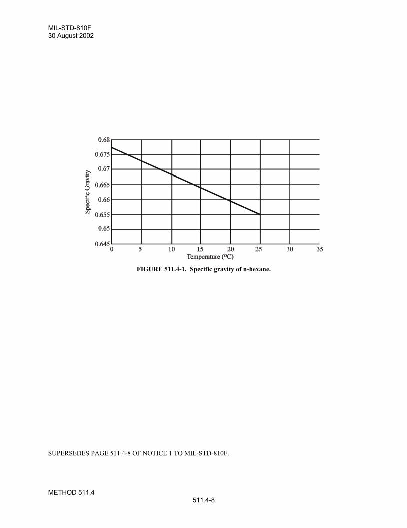
MIL-STD-810F30 August 2002
METHOD 511.4511.4-8
FIGURE 511.4-1. Specific gravity of n-hexane.
SUPERSEDES PAGE 511.4-8 OF NOTICE 1 TO MIL-STD-810F.
MIL-STD-810F30 August 2002
METHOD 513.5513.5-11
4.4 Test Execution.
4.4.1 Preparation for test.
4.4.1.1 Inspections.All items require a pretest standard ambient checkout to provide baseline data and additional inspections andperformance checks during and after tests. Conduct inspections as follows:
Step 1. Examine the test item for physical defects, etc.Step 2. Prepare the test item for test, in its operating configuration if required, as specified in the test plan.Step 3. Obtain sufficient dimensional measurements of the test item to provide a reference guide for the
evaluation of physical damage that may be induced during the tests.Step 4. Examine the test item/fixture/centrifuge/sled combination for compliance with the test item and test
plan requirements.Step 5. If applicable, conduct an operational checkout in accordance with the test plan and document the
results.Step 6. Document the results.
4.4.1.2 Mounting of the test item.Configure the test item for service application. Mount the test item on the test apparatus using the hardware that isnormally used to mount the materiel in its service installation.
a. Centrifuge mounting.
Step 1. Determine the location for the test item by measurement from the center of rotation of the centrifugeto the location on the centrifuge arm that will provide the g level established for the test. Mount thetest item so that its geometric center is at the location on the arm determined for the test load factor(g level). Calculate test levels as follows:
NT = K r n2
Where: NT = test load factor (load factor normal to the centrifuge plane of rotation)K = 1.118 x 10⁻³, r in meters (K = 2.840 x 10⁻⁵, r in inches)r = radial distance in meters, (inches) from the center of rotation to the mounting
location on centrifuge armn = angular velocity of centrifuge arm in revolutions per minute (rpm)
Step 2. Orient the test item on the centrifuge for the six test direction conventions as follows:
(a) Fore. Front or forward end of test item facing toward center of centrifuge.
(b) Aft. Reverse the test item 180 degrees from fore position.
(c) Up. Top of test item facing toward center of centrifuge.
(d) Down. Reverse item 180 degrees from up position.
(e) Lateral left. Left side of test item facing toward center of centrifuge.
(f) Lateral right. Right side of test item facing toward center of centrifuge.
Step 3. After the test item is properly oriented and mounted on the centrifuge, make measurements andcalculations to ensure the end of the test item nearest to the center of the centrifuge will be subjectedto no less than 90 percent of the g level established for the test. If the g level is found to be less than90 percent of the established g level, either mount the test item further out on the centrifuge arm andadjust the rotational speed accordingly, or use a larger centrifuge to ensure the end of the test itemnearest to the center of the centrifuge is subjected to at least 90 percent of the established g level.However, do not subject the opposite end of the test item (the end farthest from the center of thecentrifuge) to over 110 percent of the established g level. For large test items, consider exceptions
SUPERSEDES PAGE 513.5-11 OF MIL-STD-810F.
MIL-STD-810F1 January 2000
METHOD 513.5513.5-12
for load gradients based on the existing availability of large centrifuges in commercial orgovernment test facilities.
b. Track/rocket-powered-sled mounting. For track/rocket-powered-sled mounting, mount the test item andassociated test fixture or apparatus on the sled platform in accordance with the controlled accelerationdirection of the sled. (Ensure the test fixture or apparatus has been designed to isolate sled vibrationsfrom the test item.) Since the sled and test item experience the same g levels, only the orientation of thetest item on the sled is critical. Orient the test item on the sled according to the acceleration directionsshown on figure 513.5-1 and the controlled acceleration direction of the sled for the six test directions.
4.4.2 Procedure I - Structural Test.Step 1. Install the test item and place it in its operational mode and orientation as in paragraph 4.4.1.2.Step 2. Bring the centrifuge to the speed required to induce the specified g level in the test item as
determined from paragraph 2.3 and table 513.5-I for the particular test item orientation. Maintainthis g level for at least one minute after the centrifuge rpm has stabilized.
Step 3. Functionally test and inspect the test item as specified in paragraph 4.4.1.1.Step 4. Repeat this test procedure for the remaining five test directions noted in paragraph 4.4.1.2.a, Step 2.Step 5. Upon completing the tests in the six test directions, functionally test and inspect the test item as
specified in paragraph 4.4.1.1.
4.4.3 Procedure II - Operational Test.
4.4.3.1 Centrifuge.Step 1. Install the test item and place it in its operational mode and orientation as in paragraph 4.4.1.2.Step 2. Functionally test and inspect the test item as specified in paragraph 4.4.1.1.Step 3. With the test item operating, bring the centrifuge to the speed required to induce specified g level in
the test item as determined from paragraph 2.3 and table 513.5-II for the particular test itemorientation. Maintain this g level for at least one minute after the centrifuge rpm has stabilized.Conduct a performance check and document the results.
Step 4. Stop the centrifuge and inspect the test item as specified in paragraph 4.4.1.1.Step 5. Repeat Steps 1-3 for the five remaining orientations noted in paragraph 4.4.1.2.a, Step 2.Step 6. Upon completing the tests in the six test directions, functionally check and inspect the test item
according to paragraph 4.4.1.1.
4.4.3.2 Track/rocket-powered-sled.Step 1. Install the test item and place it in its operational mode and orientation as in paragraph 4.4.1.2.Step 2. Functionally test and inspect the test item as specified in paragraph 4.4.1.1.Step 3. With the test item operating, accelerate the sled to the level required to induce the specified g level
in the test item as determined from paragraph 2.3 and table 513.5-II for the particular test itemorientation. Conduct a performance check while the test item is subjected to the specified g level.Document the results.
Step 4. Evaluate test run parameters and determine if the required test accelerations were achieved. Repeatthe test run as necessary to demonstrate acceptable performance of the test item while underrequired test acceleration. Document test run parameters.
Step 5. Repeat this test procedure for the five remaining test directions noted in paragraph 4.4.1.2.a, Step 2.Upon completing the tests in the six test directions, functionally check and inspect the test itemaccording to paragraph 4.4.1.1.
4.4.4 Procedure III - Crash Safety Test.Step 1. Install the test item and place it in its operational mode and orientation as in paragraph 4.4.1.2.Step 2. Bring the centrifuge to the speed required to induce the specified g level in the test item as
determined from paragraph 2.3 and table 513.5-III for the particular test item orientation. Maintainthis g level for at least one minute after the centrifuge rpm has stabilized.
REPRINTED WITHOUT CHANGE.
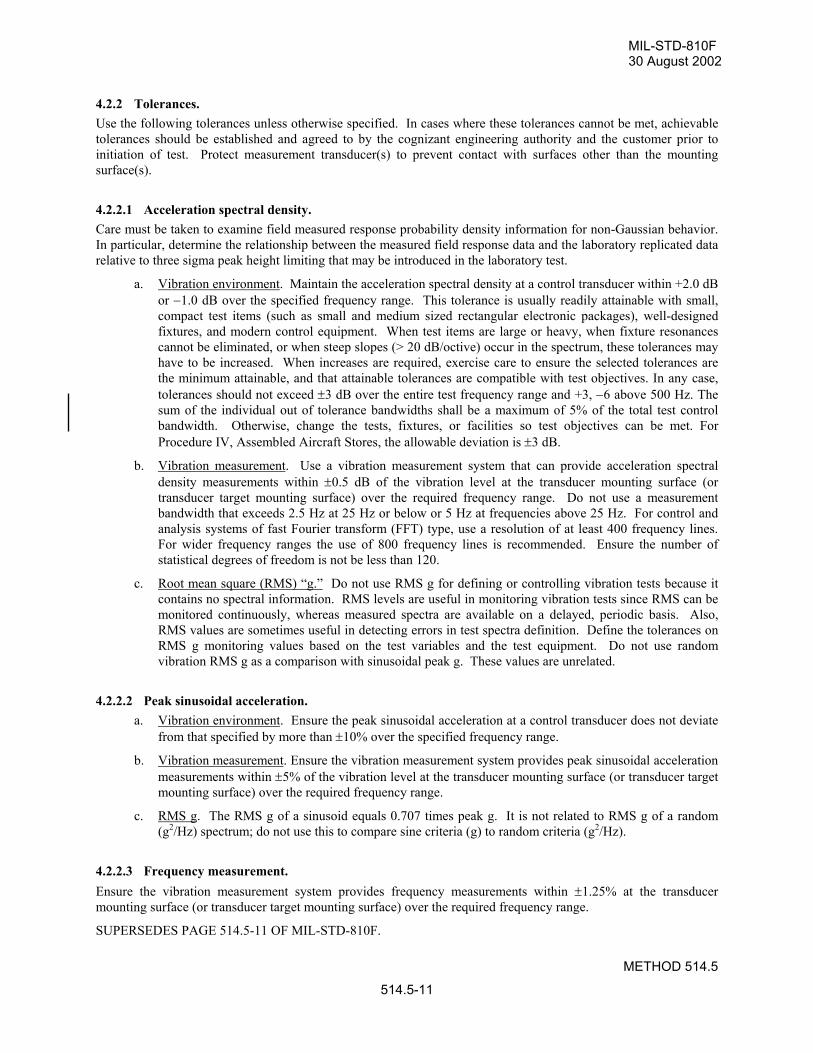
MIL-STD-810F30 August 2002
METHOD 514.5
514.5-11
4.2.2 Tolerances.Use the following tolerances unless otherwise specified. In cases where these tolerances cannot be met, achievabletolerances should be established and agreed to by the cognizant engineering authority and the customer prior toinitiation of test. Protect measurement transducer(s) to prevent contact with surfaces other than the mountingsurface(s).
4.2.2.1 Acceleration spectral density.Care must be taken to examine field measured response probability density information for non-Gaussian behavior.In particular, determine the relationship between the measured field response data and the laboratory replicated datarelative to three sigma peak height limiting that may be introduced in the laboratory test.
a. Vibration environment. Maintain the acceleration spectral density at a control transducer within +2.0 dBor −1.0 dB over the specified frequency range. This tolerance is usually readily attainable with small,compact test items (such as small and medium sized rectangular electronic packages), well-designedfixtures, and modern control equipment. When test items are large or heavy, when fixture resonancescannot be eliminated, or when steep slopes (> 20 dB/octive) occur in the spectrum, these tolerances mayhave to be increased. When increases are required, exercise care to ensure the selected tolerances arethe minimum attainable, and that attainable tolerances are compatible with test objectives. In any case,tolerances should not exceed ±3 dB over the entire test frequency range and +3, −6 above 500 Hz. Thesum of the individual out of tolerance bandwidths shall be a maximum of 5% of the total test controlbandwidth. Otherwise, change the tests, fixtures, or facilities so test objectives can be met. ForProcedure IV, Assembled Aircraft Stores, the allowable deviation is ±3 dB.
b. Vibration measurement. Use a vibration measurement system that can provide acceleration spectraldensity measurements within ±0.5 dB of the vibration level at the transducer mounting surface (ortransducer target mounting surface) over the required frequency range. Do not use a measurementbandwidth that exceeds 2.5 Hz at 25 Hz or below or 5 Hz at frequencies above 25 Hz. For control andanalysis systems of fast Fourier transform (FFT) type, use a resolution of at least 400 frequency lines.For wider frequency ranges the use of 800 frequency lines is recommended. Ensure the number ofstatistical degrees of freedom is not be less than 120.
c. Root mean square (RMS) “g.” Do not use RMS g for defining or controlling vibration tests because itcontains no spectral information. RMS levels are useful in monitoring vibration tests since RMS can bemonitored continuously, whereas measured spectra are available on a delayed, periodic basis. Also,RMS values are sometimes useful in detecting errors in test spectra definition. Define the tolerances onRMS g monitoring values based on the test variables and the test equipment. Do not use randomvibration RMS g as a comparison with sinusoidal peak g. These values are unrelated.
4.2.2.2 Peak sinusoidal acceleration.a. Vibration environment. Ensure the peak sinusoidal acceleration at a control transducer does not deviate
from that specified by more than ±10% over the specified frequency range.
b. Vibration measurement. Ensure the vibration measurement system provides peak sinusoidal accelerationmeasurements within ±5% of the vibration level at the transducer mounting surface (or transducer targetmounting surface) over the required frequency range.
c. RMS g. The RMS g of a sinusoid equals 0.707 times peak g. It is not related to RMS g of a random(g2/Hz) spectrum; do not use this to compare sine criteria (g) to random criteria (g2/Hz).
4.2.2.3 Frequency measurement.Ensure the vibration measurement system provides frequency measurements within ±1.25% at the transducermounting surface (or transducer target mounting surface) over the required frequency range.
SUPERSEDES PAGE 514.5-11 OF MIL-STD-810F.
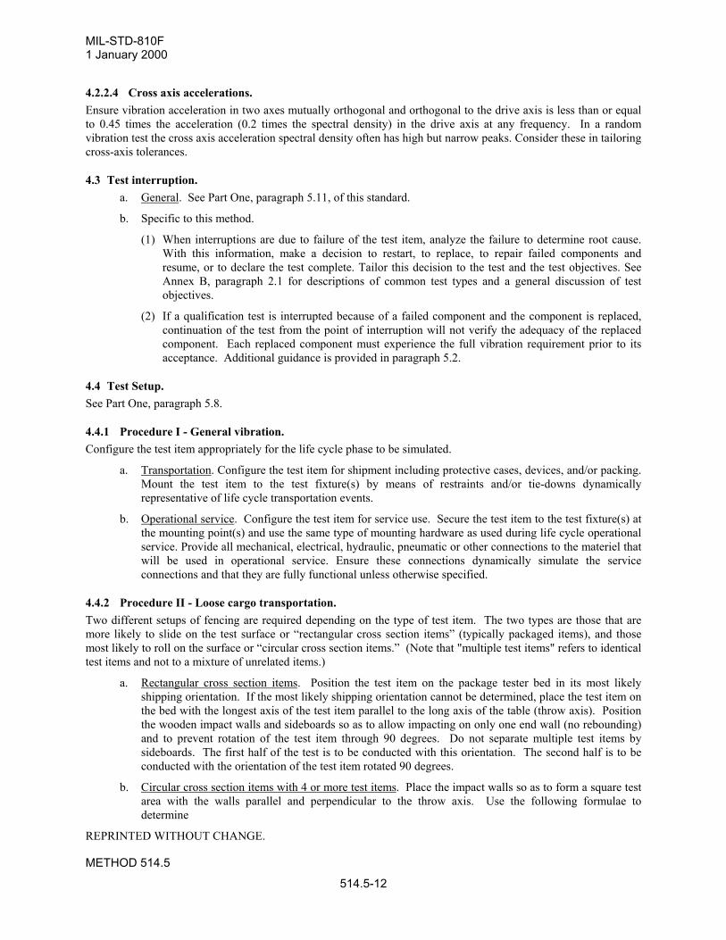
MIL-STD-810F1 January 2000
METHOD 514.5
514.5-12
4.2.2.4 Cross axis accelerations.Ensure vibration acceleration in two axes mutually orthogonal and orthogonal to the drive axis is less than or equalto 0.45 times the acceleration (0.2 times the spectral density) in the drive axis at any frequency. In a randomvibration test the cross axis acceleration spectral density often has high but narrow peaks. Consider these in tailoringcross-axis tolerances.
4.3 Test interruption.a. General. See Part One, paragraph 5.11, of this standard.
b. Specific to this method.
(1) When interruptions are due to failure of the test item, analyze the failure to determine root cause.With this information, make a decision to restart, to replace, to repair failed components andresume, or to declare the test complete. Tailor this decision to the test and the test objectives. SeeAnnex B, paragraph 2.1 for descriptions of common test types and a general discussion of testobjectives.
(2) If a qualification test is interrupted because of a failed component and the component is replaced,continuation of the test from the point of interruption will not verify the adequacy of the replacedcomponent. Each replaced component must experience the full vibration requirement prior to itsacceptance. Additional guidance is provided in paragraph 5.2.
4.4 Test Setup.See Part One, paragraph 5.8.
4.4.1 Procedure I - General vibration.Configure the test item appropriately for the life cycle phase to be simulated.
a. Transportation. Configure the test item for shipment including protective cases, devices, and/or packing.Mount the test item to the test fixture(s) by means of restraints and/or tie-downs dynamicallyrepresentative of life cycle transportation events.
b. Operational service. Configure the test item for service use. Secure the test item to the test fixture(s) atthe mounting point(s) and use the same type of mounting hardware as used during life cycle operationalservice. Provide all mechanical, electrical, hydraulic, pneumatic or other connections to the materiel thatwill be used in operational service. Ensure these connections dynamically simulate the serviceconnections and that they are fully functional unless otherwise specified.
4.4.2 Procedure II - Loose cargo transportation.Two different setups of fencing are required depending on the type of test item. The two types are those that aremore likely to slide on the test surface or “rectangular cross section items” (typically packaged items), and thosemost likely to roll on the surface or “circular cross section items.” (Note that "multiple test items" refers to identicaltest items and not to a mixture of unrelated items.)
a. Rectangular cross section items. Position the test item on the package tester bed in its most likelyshipping orientation. If the most likely shipping orientation cannot be determined, place the test item onthe bed with the longest axis of the test item parallel to the long axis of the table (throw axis). Positionthe wooden impact walls and sideboards so as to allow impacting on only one end wall (no rebounding)and to prevent rotation of the test item through 90 degrees. Do not separate multiple test items bysideboards. The first half of the test is to be conducted with this orientation. The second half is to beconducted with the orientation of the test item rotated 90 degrees.
b. Circular cross section items with 4 or more test items. Place the impact walls so as to form a square testarea with the walls parallel and perpendicular to the throw axis. Use the following formulae todetermine
REPRINTED WITHOUT CHANGE.
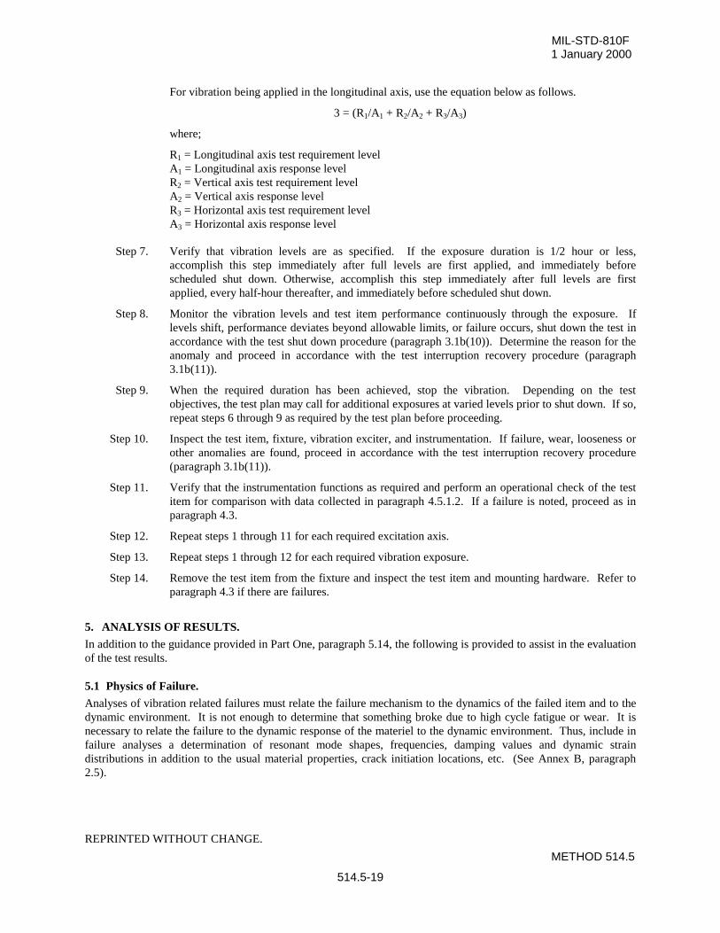
MIL-STD-810F1 January 2000
METHOD 514.5
514.5-19
For vibration being applied in the longitudinal axis, use the equation below as follows.
3 = (R1/A1 + R2/A2 + R3/A3)
where;
R1 = Longitudinal axis test requirement levelA1 = Longitudinal axis response levelR2 = Vertical axis test requirement levelA2 = Vertical axis response levelR3 = Horizontal axis test requirement levelA3 = Horizontal axis response level
Step 7. Verify that vibration levels are as specified. If the exposure duration is 1/2 hour or less,accomplish this step immediately after full levels are first applied, and immediately beforescheduled shut down. Otherwise, accomplish this step immediately after full levels are firstapplied, every half-hour thereafter, and immediately before scheduled shut down.
Step 8. Monitor the vibration levels and test item performance continuously through the exposure. Iflevels shift, performance deviates beyond allowable limits, or failure occurs, shut down the test inaccordance with the test shut down procedure (paragraph 3.1b(10)). Determine the reason for theanomaly and proceed in accordance with the test interruption recovery procedure (paragraph3.1b(11)).
Step 9. When the required duration has been achieved, stop the vibration. Depending on the testobjectives, the test plan may call for additional exposures at varied levels prior to shut down. If so,repeat steps 6 through 9 as required by the test plan before proceeding.
Step 10. Inspect the test item, fixture, vibration exciter, and instrumentation. If failure, wear, looseness orother anomalies are found, proceed in accordance with the test interruption recovery procedure(paragraph 3.1b(11)).
Step 11. Verify that the instrumentation functions as required and perform an operational check of the testitem for comparison with data collected in paragraph 4.5.1.2. If a failure is noted, proceed as inparagraph 4.3.
Step 12. Repeat steps 1 through 11 for each required excitation axis.
Step 13. Repeat steps 1 through 12 for each required vibration exposure.
Step 14. Remove the test item from the fixture and inspect the test item and mounting hardware. Refer toparagraph 4.3 if there are failures.
5. ANALYSIS OF RESULTS.
In addition to the guidance provided in Part One, paragraph 5.14, the following is provided to assist in the evaluationof the test results.
5.1 Physics of Failure.
Analyses of vibration related failures must relate the failure mechanism to the dynamics of the failed item and to thedynamic environment. It is not enough to determine that something broke due to high cycle fatigue or wear. It isnecessary to relate the failure to the dynamic response of the materiel to the dynamic environment. Thus, include infailure analyses a determination of resonant mode shapes, frequencies, damping values and dynamic straindistributions in addition to the usual material properties, crack initiation locations, etc. (See Annex B, paragraph2.5).
REPRINTED WITHOUT CHANGE.
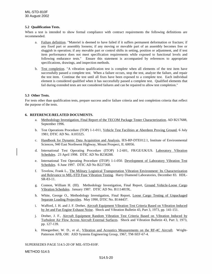
MIL-STD-810F30 August 2002
METHOD 514.5
514.5-20
5.2 Qualification Tests.
When a test is intended to show formal compliance with contract requirements the following definitions arerecommended.
a. Failure definition. "Materiel is deemed to have failed if it suffers permanent deformation or fracture; ifany fixed part or assembly loosens; if any moving or movable part of an assembly becomes free orsluggish in operation; if any movable part or control shifts in setting, position or adjustment, and if testitem performance does not meet specification requirements while exposed to functional levels andfollowing endurance tests." Ensure this statement is accompanied by references to appropriatespecifications, drawings, and inspection methods.
b. Test completion. "A vibration qualification test is complete when all elements of the test item havesuccessfully passed a complete test. When a failure occurs, stop the test, analyze the failure, and repairthe test item. Continue the test until all fixes have been exposed to a complete test. Each individualelement is considered qualified when it has successfully passed a complete test. Qualified elements thatfail during extended tests are not considered failures and can be repaired to allow test completion."
5.3 Other Tests.
For tests other than qualification tests, prepare success and/or failure criteria and test completion criteria that reflectthe purpose of the tests.
6. REFERENCE/RELATED DOCUMENTS.
a. Methodology Investigation, Final Report of the TECOM Package Tester Characterization, AD B217688,September 1996.
b. Test Operations Procedure (TOP) 1-1-011, Vehicle Test Facilities at Aberdeen Proving Ground, 6 July1981; DTIC AD No. A103325.
c. Handbook for Dynamic Data Acquisition and Analysis, IES-RP-DTE012.1, Institute of EnvironmentalSciences, 940 East Northwest Highway, Mount Prospect, IL 60056.
d. International Test Operating Procedure (ITOP) 1-2-601, FR/GE/UK/US. Laboratory VibrationSchedules. 23 April 1998. DTIC AD No B238288.
e. International Test Operating Procedure (ITOP) 1-1-050. Development of Laboratory Vibration TestSchedules. 6 June 1997. DTIC AD No B227368.
f. Tevelow, Frank L., The Military Logistical Transportation Vibration Environment: Its Characterizationand Relevance to MIL-STD Fuse Vibration Testing. Harry Diamond Laboratories, December 83. HDL-SR-83-11.
g. Connon, William H. (III). Methodology Investigation, Final Report, Ground Vehicle-Loose CargoVibration Schedules. January 1987. DTIC AD No. B1114819L.
h. White, George O., Methodology Investigation, Final Report, Loose Cargo Testing of UnpackagedSeparate Loading Projectiles. May 1990, DTIC No. B144437.
i. Wafford, J. H. and J. F. Dreher, Aircraft Equipment Vibration Test Criteria Based on Vibration Inducedby Jet and Fan Engine Exhaust Noise. Shock and Vibration Bulletin 43, Part 3, 1973, pp. 141-151.
j. Dreher, J. F., Aircraft Equipment Random Vibration Test Criteria Based on Vibration Induced byTurbulent Air Flow Across Aircraft External Surfaces. Shock and Vibration Bulletin 43, Part 3, 1973,pp. 127-139.
k. Hinegardner, W. D., et al., Vibration and Acoustics Measurements on the RF-4C Aircraft. Wright-Patterson AFB, OH: ASD Systems Engineering Group, 1967, TM-SEF-67-4.
SUPERSEDES PAGE 514.5-20 OF MIL-STD-810F.
MIL-STD-810F1 January 2000
METHOD 514.5
514.5-21
l. Bartel, H. W and J. M. McAvoy, Cavity Oscillation in Cruise Missile Carrier Aircraft. Air Force WrightAeronautical Laboratories, June 1981. AFWAL-TR-81-3036.
m. Tipton, A. G., Weapon Bay Cavity Noise Environments Data Correlation and Prediction for theB-1 Aircraft. Air Force Wright Aeronautical Laboratories, June 1980. AFWAL-TR-80-3050.
n. Thomas, C. E., Flight Survey of C-130A Aircraft. March 1972. ASD-TR-62-2167. DTIC No.AD-274-904.
o. Bolds, P. G., Flight Vibration Survey C-133 Aircraft. April 1972. ASD-TDR-62-383. DTIC No.AD-277-128.
p. Kuhn, D. L., Analysis of the Vibration Environment for Airborne Reconnaissance Integrated ElectronicsSystem (ARIES) Installed on EP-3E Aircraft. Indianapolis: Naval Avionics Center 443, 1975.Document No. ESL-163.
q. Kuhn, D. L. and R. M. Johnson., Evaluation of the Vibration Environment for the Doppler RangingInformation System. Indianapolis: Naval Avionics Center 443, 1982. Document No. ESL-420.
r. Analysis of the Vibration Environment for TACAMO IV B System Installed on ED-130 Aircraft.Indianapolis: Naval Avionics Center 443, 1976. Document No. ESL-199.
s. Kuhn, D. L., Evaluation of Flight Data for the Big Look Antenna System OE-319/APS Installed onEP-3E aircraft. Indianapolis: Naval Avionics Center 443, 1981. Document No. ESL-418.
t. Kuhn, D. L., Analysis of Flight Data for Deepwell System Installed in EP-3E Aircraft. Indianapolis:Naval Avionics Center 443, 1975. Document No. ESL-169.
u. Dreher, J. F., E. D. Lakin, and E. A. Tolle, Vibroacoustic Environment and Test Criteria for AircraftStores During Captive Flight. Shock and Vibration Bulletin 39, Supplement (1969), pp. 15-40.
v. Dreher, J. F., Effects of Vibration and Acoustical Noise on Aircraft/Stores Compatibility. Aircraft StoreSymposium Proceedings, Vol. 6, November 1969.
w. Piersol, A. G., Vibration and Acoustic Test Criteria for Captive Flight of Externally Carried Stores,December 1971. AFFDL-TR-71-158. DTIC No. AD-893-005L.
x. Frost, W. G., P. B. Tucker, and G. R. Waymon, Captive Carriage Vibration of Air-to-Air Missiles onFighter Aircraft. Journal of Environmental Sciences, 21:15, (September/October 1978), pp. 11-15.
y. Mechanical Vibrations; Den Hartog, J. P., Fourth Edition, McGraw-Hill Book Company, 1956.
z. A Modern Course in Aeroelasticity. Dowell, E. H., et al, Second Edition, Kluwer Academic Publisher,1989.
aa. Shock and Vibration Handbook. Edited by Harris, Cyril M. and Charles E. Crede; McGraw-Hill BookCompany.
bb. Bendat, Julius S., and Piersol, Allan G., Engineering Applications of Correlation and Spectral Analysis,2nd Edition, John Wiley & Sons, Inc., New York, 1993.
cc. Allemang, Randall J. and David L. Brown, Experimental Modal Analysis and Dynamic ComponentSynthesis - Measurement Techniques for Experimental Modal Analysis. Vol. II. December 1987.AFWAL-TR-87-3069.
dd. Allemang, Randall J. and David L. Brown, Experimental Modal Analysis and Dynamic ComponentSynthesis - Modal Parameter Estimation. Vol. III. December 1987. AFWAL-TR-87-3069.
ee. Allemang, Randall J. and David L. Brown, Experimental Modal Analysis and Dynamic ComponentSynthesis - System Modeling Techniques. Vol. VI. December 1987. AFWAL-TR-87-3069.
ff. Airplane Aerodynamics, Dommasch, Daniel O, Sidney S. Sherby and Thomas F. Connolly, PitmanPublishing Corporation, 1958.
REPRINTED WITHOUT CHANGE.

MIL-STD-810F30 August 2002
METHOD 514.5
514.5-22
gg. U.S. Standard Atmosphere, 1962.
hh. MIL-STD-167-1, Mechanical Vibrations of Shipboard Equipment (Type I - Environmental andType II - Internally Excited).
ii. Mission Environmental Requirements Integration Technology (MERIT), Final Report (draft),15 September 1996, McDonald Douglas Aerospace.
SUPERSEDES PAGE 514.5-22 OF MIL-STD-810F.
MIL-STD-810F1 January 2000ANNEX A
METHOD 514.5514.5A-5
(2) Belgian block 24 km/hr
(3) Radial washboard (50 mm to 100 mm waves) 24 km/hr
(4) Two inch washboard (50 mm) 16 km/hr
(5) Three inch spaces bump (75 mm) 32 km/hr
b. Exposure durations. Ensure the durations (distances over) of each test course segment/speedcombination are in accordance with the scenario(s) of the Life Cycle Environment Profile.
2.2.4 Category 7 - Aircraft - jet.
Cargo vibration environments on jet aircraft are broadband random in nature. The maximum vibrations are usuallyengine exhaust noise generated and occur during takeoff. Levels drop off rapidly after takeoff to lower level cruiselevels that are boundary layer noise generated. These sources are discussed in Annex A, paragraph 2.3.1.
a. Low frequency vibration. Vibration criteria typically begins at 15 Hz. At frequencies below 15 Hz, it isassumed that the cargo does not respond dynamically (see Annex B, paragraph 2.4). Airframe lowfrequency vibration (gust response, landing impact, maneuvers, etc.) is experienced as steady inertialloads (acceleration). That part of the environment is included in method 513.5.
b. Large cargo items. Cargo items that are large relative to the airframe in dimensions and/or mass mayinteract with aircraft structural dynamics (see Annex B, paragraph 2.4). This is particularly true if themateriel has natural frequencies below 20 Hz. This interaction may have serious consequences withregard to aircraft loads and flutter. Evaluate materiel that fits this description by the aircraft structuralengineers prior to carriage. Contact the System Program Office responsible for the aircraft type for thisevaluation.
c. Exposure levels.
(1) Vibration qualification criteria for most jet cargo airplanes are available through the System ProgramOffice responsible for the aircraft type. These criteria are intended to qualify equipment forpermanent installation on the airplanes and are conservative for cargo. However, function criteriafor equipment located in the cargo deck zones can be used for cargo if necessary. The guidance ofAnnex A, paragraph 2.3.1 can also be used to generate conservative criteria for specific airplanesand cargo.
(2) Annex C, figure 514.5C-6 shows the cargo compartment zone functional qualification levels of theC-5, C/KC-135, C-141, E-3, KC-10, and T-43 aircraft. Also, shown on the figure is a curve labeled"General Exposure." These are the recommended criteria for jet aircraft cargo. This curve is basedon the worst case zone requirements of the most common military jet transports so that even thoughit does not envelope all peaks in the various spectra, it should still be mildly conservative for cargo.Also, since it does not allow the valleys in the individual spectra, it should cover other jet transportswith different frequency characteristics. The envelope represents take-off, the worst case for cargo.Vibration during other flight conditions is substantially less.
d. Exposure durations. When Annex C, figure 514.5C-6 is used, select a duration of one minute pertakeoff. Determine the number of takeoffs from the Life Cycle Environment Profile. Otherwise, takedurations from the Life Cycle Environment Profile.
2.2.5 Category 8 - Aircraft - propeller.
Cargo vibration environments on propeller aircraft are dominated by relatively high amplitude, approximatelysinusoidal spikes at propeller passage frequency and harmonics. Because of engine speed variations, the frequenciesof the spikes vary over a bandwidth. There is wide band vibration at lower levels across the spectra. This wide bandvibration is primarily due to boundary layer flow over the aircraft. These sources are discussed in Annex A,paragraph 2.3.2.
REPRINTED WITHOUT CHANGE.
MIL-STD-810F30 August 2002ANNEX A
METHOD 514.5
514.5A-6
a. Low frequency vibration. Vibration criteria typically begin at 15 Hz. At frequencies below 15 Hz it isassumed that the cargo does not respond dynamically (see Annex B, paragraph 2.4). Airframe lowfrequency vibration (gust response, landing impact, maneuvers, etc.) are experienced as steady inertialloads (acceleration). That part of the environment is included in method 513.
b. Large cargo items. Cargo items that are large relative to the airframe in dimensions and/or mass mayinteract with aircraft structural dynamics (see Annex B, paragraph 2.4). This is particularly true if themateriel has natural frequencies below 20 Hz. This interaction may have serious consequences withregard to aircraft loads and flutter. Materiel that fits this description must be evaluated by aircraftstructural engineers prior to carriage. Contact the System Program Office responsible for the aircrafttype for this evaluation.
c. Exposure levels. Contact the System Program Office responsible for the aircraft for vibration criteria. Ifno criteria are available, measurements of cargo deck vibration in the aircraft are recommended. As alast resort the guidance of Annex A, paragraph 2.3.2 can be used.
d. Exposure durations. Take durations from the Life Cycle Environment Profile.
2.2.6 Category 9 - Aircraft - helicopter.a. Environment characterization. Vibration of cargo carried in helicopters is characterized by a continuous
wideband, low-level background with strong narrowband peaks superimposed. This environment is acombination of many sinusoidal or near sinusoidal components due to main and tail rotors, rotatingmachinery and low-level random components due to aerodynamic flow. These sources are discussed inAnnex A, paragraph 2.3.3.
b. Sling loads. Cargo carried as sling loads below a helicopter is normally subjected to low level randomvibration due to turbulent flow around the cargo with narrow band peaks due to helicopter main rotorblade passage. In addition, there will be low frequency (primarily vertical) motions due to the slingsuspension modes (similar to vibration isolator modes, see Annex B, paragraph 2.4.2). Choose slingsbased on sling stiffness and suspended mass such that suspension frequencies (fs) do not coincide withhelicopter main rotor forcing frequencies (f i). Ensure suspension frequencies are not within a factor oftwo of forcing frequencies (fs < fi / 2 or fs > 2 fi). Determine main rotor forcing frequencies (shaftrotation frequency, blade passage frequency, and harmonics) for several helicopters from Annex C, table514.5C-IV. When inappropriate combinations of cargo and slings are used, violent vibration can occur.The cargo is likely to be dropped to protect the helicopter.
c. Exposure levels.
(1) Helicopter internal cargo vibration is a complex function of location within the helicopter cargo bayand the interaction of the cargo mass and stiffness with the helicopter structure. Measurements ofthe vibration of the cargo in the specific helicopter are necessary to determine vibration with anyaccuracy. Approximate criteria may be derived from Annex A, paragraph 2.3.3. Additionaltailored helicopter vibration schedules are provided in reference d.
(2) There is no current source of data to define slung cargo vibration levels. However, these levelsshould be low and should not be a significant factor in design of materiel that has a reasonabledegree of ruggedness. Materiel that has been designed for vibration levels and durations equal to orexceeding the suggested minimum integrity test of Annex A, paragraph 2.4.1 should not be affectedby this environment.
(3) Exposure durations. Take durations from the Life Cycle Environment Profile or from reference f.
2.2.7 Category 10 - Ship - surface ship.The vibration environment of cargo carried in ships is fundamentally the same as for materiel installed on ships. SeeAnnex A, paragraph 2.3.10.
SUPERSEDES PAGE 514.5A-6 OF MIL-STD-810F.
MIL-STD-810F1 January 2000ANNEX A
METHOD 514.5514.5A-9
vanes, and propellers. These machines produce the fixed frequency spikes of Annex C, figure 514.5C-9.These spikes have a bandwidth because there is minor rpm drift, the vibration is not pure sinusoidal(Annex B, paragraph 2.3.3), and to account for materiel resonant frequency differences as modeled ortested and as manufactured and installed on the aircraft.
b. Varying propeller speed. When propeller speed varies during operation, a spectrum or set of spectrasimilar to Annex C, figure 514.5C-9 is required to define vibration levels. The spikes on these spectrawould have bandwidths encompassing the propeller speed variations of operation. Separate spectra maybe required to describe individual mission segments.
c. Source dwell testing. These vibration environments can be approximated in the laboratory by the sourcedwell test described in Annex B, paragraph 2.3.3. Vibration problems in this type of environment aretypically associated with the coincidence of materiel vibration modes and excitation spikes. Intelligentdesigns use notches between spikes as safe regions for materiel vibration modes. It is particularlyimportant to assure that vibration isolation frequencies do not coincide with spike frequencies. Sourcedwell tests minimize the likelihood that materiel will be overstressed at non-representative conditions,and ensure reasonable design provisions will not be subverted.
d. Exposure levels. Whenever possible, use flight vibration measurements to develop vibration criteria. Inthe absence of flight measurements, the levels of Annex C, table 514.5C-II can be used with the spectraof Annex C, figure 514.5C-9. These levels are based on C-130 and P-3 aircraft measurements(references p through t) and are fairly representative of the environments of these aircraft. The decline ofspike acceleration spectral density with frequency is based on data analyzed in a spectral density format.
e. Exposure durations. Take durations from the Life Cycle Environment Profile.
2.3.3 Category 14 - Rotary wing aircraft - helicopter.
Helicopter vibration (for engine-mounted materiel, see Annex A, paragraph 2.3.11, and for gunfire inducedvibration, see method 519.5) is characterized by dominant peaks superimposed on a broadband background, asdepicted in Annex C, figure 514.5C-10. The peaks are sinusoids produced by the major rotating components (mainrotor, tail rotor, engine, gearboxes, shafting, etc.). The peaks occur at the rotation speed (frequency) of eachcomponent (i.e., 1P for main rotor, 1T for tail rotor, and 1S where S designates a locally predominate rotatingelement) and harmonics of these speeds (e.g., 2P, 3P, 4P). The broadband background is a mixture of loweramplitude sinusoids and random vibrations due to sources such as aerodynamic flow noise (see Annex A, paragraph2.3.1). Vibration levels and spectrum shapes vary widely between helicopter types and throughout each helicopter,depending on strength and location of sources and the geometry and stiffness of the structure. Thus, the need formeasured data is acute.
a. Broadband background. The broadband background is expressed as random vibration for design and testpurposes as a matter of expediency. The definition of and application to design and test of all lower levelsinusoidal and random components is not practical.
b. Dominant sinusoids. The dominant sinusoids are generated by rotating components of the helicopter,primarily the main rotor(s), but also tail rotor, engine(s), drive shafts, and gear meshing. The normaloperating speeds of these components are generally constant, varying less than five percent. However,recent designs have taken advantage of variable rotor speed control that generates a pseudo steady staterotor speed at values between 95 and 110 per cent of the nominal rotor speed. This complicates themateriel design and test process since all rotating component speeds, pseudo or otherwise, should beaccounted for.
c. Variable rotor speeds. Variable speed helicopters are also possible; in this case they also account for thefull range of rotation speeds. A range of 0.975 times minimum speed to 1.025 times maximum speed isrecommended.
d. Design practice. An obvious requirement for helicopter materiel design is to avoid a match or near matchbetween materiel resonant frequencies and the dominant sinusoids. A minimum clearance between
REPRINTED WITHOUT CHANGE.
MIL-STD-810F30 August 2002ANNEX A
METHOD 514.5
514.5A-10
operating speed and resonant frequency of at least five per cent is recommended. It is important to notethat helicopter frequencies and amplitudes are unique for each helicopter type and, to some degree, eachmodel of a given type.
e. Exposure levels.
(1) For reasons stated above, the exposure levels for materiel installed in helicopters should be derivedfrom field measurement (additional tailored helicopter vibration schedules are provided inreference d). When measured data are not available, levels can be derived from Annex C, figures514.5C-10 and 514.5C-11, and table 514.5C-IV. These levels are intended to envelope potentialworst-case environments. They do not represent environments under which vibration sensitivemateriel should be expected to perform to specification. However, the materiel is expected tosurvive undamaged and to function to specification at the completion of the test. Materiel costs areoften strongly influenced by the performance required in a vibration environment. Consequently,field measurement based vibration criteria can be very important.
(2) To determine levels, divide the aircraft into zones as shown in Annex C, figure 514.5C-11. Use thesource frequencies of the main rotor in determining the values of A1, A2, A3, and A4 (Annex C,table 514.5C-IV) for all materiel locations except those defined below. For materiel located in thehorizontal projection of the tail rotor disc, use the source frequencies of the tail rotor. In addition,ensure criteria for materiel located in an overlap of main and tail rotor zones includes both sets offrequencies. Fundamental main and tail rotor source frequencies of several helicopters are given inAnnex C, table 514.5C-IV. For materiel located on or in close proximity to drive train componentssuch as gearboxes and drive shafts, use the source frequencies of that drive train component (i.e.,gear mesh frequencies, shaft rotational speeds). Determine these from the drive train data for theparticular helicopter.
f. Exposure durations. When measured data are used to establish exposure levels, take durations from theLife Cycle Environment Profile. When levels are derived from Annex C, figures 514.5C-10 and 514.5C-11, and table 514.5C-IV, use a duration of four (4) hours in each of three (3) orthogonal axes for a totaltest time of twelve (12) hours. This represents a 2500-hour operational life. The fatigue relationshipshown below may be used to trade test time for exposure level. Make the calculation separately for eachsinusoid and each segment of the broadband background.
t f = 4.0 (A D / A T)M
where:
t f = actual test time per axis
A D = default test amplitude
A T = actual test amplitude
M = 6 (materiel exponent for sinusoidal vibration, see Annex B, paragraph 2.2)
2.3.4 Category 15 – Aircraft stores – assembled, jet aircraft.Assembled jet aircraft stores may encounter three distinct vibration environments; external captive carriage, internalcaptive carriage, and free flight.
Note: High frequency vibration (beginning at or below 1000 Hz) cannot be practically transmitted to a storemechanically. Combine store vibration and acoustic testing (method 523.2). These test excitations in combinationproduce a much more realistic test.
a. Captive flight – external carriage. Vibration (for gunfire induced vibration see method 519.5)experienced by a store carried externally on a jet aircraft arises primarily from four sources:
SUPERSEDES PAGE 514.5A-10 OF MIL-STD-810F.
MIL-STD-810F1 January 2000ANNEX A
METHOD 514.5514.5A-13
(b) In some instances, a store is carried in one configuration or position until use. Just prior touse, the configuration or position may change, for example, a weapon carried on a rotarylauncher inside a weapons bay of a large bomber. The weapon moves from clock position toclock position as other weapons on the launcher are launched. The weapon is exposed to thebay open environment either each time another weapon is launched, or for a relatively longperiod while several are launched. Another example is a weapon that is extended out of thebay on the launch mechanism prior to launch. Here the environment will change considerablywith position. A third example is an optical sensor pod. This type of store can be carriedinternally, extended into the air stream, configuration changed (e.g., covers over opticalwindows retract), operated, configuration changed back, and retracted into the closed baymany times in a lifetime. Such variations in environment and configuration must be accountedfor.
Note: Door opening, position changes, configuration changes, door closing, etc., should be expected to happenrapidly. Each of these events and possibly a whole sequence of events can happen rapidly enough so that theyshould be treated as transient (see Annex B, paragraph 2.3.4 and Method 516.5) rather than steady-state vibration.
c. Free flight. Vibration will be experienced by stores that are deployed from aircraft, ground vehicles, orsurface ships. The sources of vibration for the free flight environment are engine exhaust noise, vibrationand noise produced by internal equipment, and boundary layer turbulence.
(1) Generally, engine exhaust noise levels will be too low to excite significant vibration in the store.This is because the engine only operates when the ratio of the exhaust velocity to the ambient airspeed is low and (except in unusual cases) the exhaust plume is behind the store.
(2) Vibration produced by onboard materiel can be severe in specific cases. Examples are ram airturbines, engines, and propellers. There is no general basis for predicting store vibrations from suchsources. Each case must be evaluated individually and it is likely that measurements will berequired.
(3) Boundary layer turbulence induced vibration should be as for captive carriage except that storevibration mode frequencies may shift, flight dynamic pressures may be different, and turbulencefrom the carrier aircraft and nearby stores will be absent.
d. Exposure levels. Select test levels and spectra for three of the vibration environments, captive flight, freeflight, and buffet from Annex C, table 514.5C-V and figures 514.5C-12 and 514.5C-13. The use of thesetables and figures is suggested only when there is an absence of satisfactory flight measurements. Exceptfor buffet portions, these criteria are closely based on references u, v, and w. These document the resultsof an extensive study and include a large amount of information and insight. The buffet criteria are basedon reference x and additional measurements and experience with the F-15 aircraft. It represents F-15wing pylon buffet that is the worst known buffet environment. F-15 fuselage store stations buffetenvironments are generally less severe. Criteria for the other environments must be determined for eachspecific case.
e. Exposure durations. Take durations from the Life Cycle Environment Profile.
2.3.5 Category 16 - Aircraft stores - materiel, jet aircraft.
Materiel installed within a jet aircraft store will experience the store vibration discussed in Annex A, paragraph2.3.4. The input exposure levels for materiel within the store are essentially the same as response levels of the store.If gunfire, cavity resonance, buffet-maneuver, and free-flight conditions occur for the store, the materiel will also beexposed to these conditions.
a. Exposure levels. Base vibration criteria on in-flight measurements when possible. If satisfactory flightmeasurements are not available, derive levels from Annex C, table 514.5C-V and 514.5C-14. Note: useinput control for vibration testing of this materiel rather than response control (see paragraph 4.2.1).
b. Exposure durations. Take durations from the Life Cycle Environment Profile.
SUPERSEDES PAGE 514.5A-13 OF MIL-STD-810F.
MIL-STD-810F30 August 2002ANNEX A
METHOD 514.5
514.5A-14
2.3.6 Category 17 - Aircraft stores - assembled/materiel, propeller aircraft.There is no known source of general guidance or measured data for the vibration of propeller aircraft stores (exceptgunfire induced, see Method 519.5). However, since the excitation sources are the same, it seems likely that storevibration will be similar to that of the carrying aircraft. See Annex A, paragraph 2.3.2; and Annex B, paragraph2.3.3 for a discussion of this vibration. Maneuver buffet vibration experienced by stores of highly-maneuverablepropeller aircraft should be similar to that experienced by jet aircraft stores. See the buffet vibration portion ofAnnex A, paragraph 2.3.4.
a. Exposure levels. There is no known source of data. For accurate definition of propeller aircraft storevibration, measurement of the actual environment is essential. The criteria of Annex C, table 514.5C-IIand figure 515.5C-9, may be used to develop preliminary estimates of general vibration. The criteria ofAnnex C, figure 514.5C-13, may be applied for maneuver buffet vibration.
b. Exposure durations. Take durations from the Life Cycle Environment Profile.
2.3.7 Category 18 - Aircraft stores - assembled/materiel, helicopter.Complex periodic waveforms characterize the service environment encountered by assembled stores carriedexternally on helicopters. Unlike stores carried on fixed-wing aircraft, externally-mounted helicopter stores receivelittle aerodynamic excitation, particularly when compared with the rotor-induced vibration. Thus, most of thevibratory energy reaches the store and materiel through the attachment points between the aircraft and the store.Some excitation, however, is added along the entire store structure due to periodic rotor-induced pressurefluctuations. The result is a complex response, unique to the particular aircraft-store configuration. Therefore,realistic definition of the environment depends almost totally upon the use of in-flight vibration measurements. Forstores exposed to gunfire, refer to Method 519.5.
a. Exposure levels. Derive exposure levels for helicopter-carried store materiel from field measurements(reference f contains criteria for specific helicopters). When measured data are not available, initialestimates can be derived from Annex C, figures 514.5C-10 and 514.5C-11, and table 514.5C-IV, priorto acquisition of field data. These levels are intended as worst-case environments and representenvironments for which it may be difficult to develop vibration sensitive materiel. Materiel costs areoften strongly influenced by the performance required in a vibration environment. Consequently, field-measurement-based vibration criteria are very important. To determine levels, locate the store relative tothe helicopter zones as shown in Annex C, figure 514.5C-11. Most stores will be inside a verticalprojection of the main rotor disc. Source frequencies of the main rotor should be used to determine thevalues of A1, A2, A3, and A4 (see Annex C, table 514.5C-IV). Fundamental main rotor sourcefrequencies of several helicopters are given in table 514.5C-IV.
b. Exposure durations. When measured data are used to establish exposure levels, take durations from theLife Cycle Environment Profile. When levels are derived from Annex C, figures 514.5C-10 and 514.5C-11, and table 514.5C-IV, use a duration of four (4) hours in each of three (3) orthogonal axes for a totaltime of twelve (12) hours. This represents a 2500-hour operational life. Use the fatigue relationship ofAnnex B, paragraph 2.2, to trade test time for exposure level. Perform the calculation separately foreach sinusoid and each segment of the broadband background.
2.3.8 Category 19 - Missiles - Tactical missiles (free flight).There is no known source of general guidance or measured data for tactical missile carriage or launch vibrationenvironments. Environments for jet aircraft, propeller aircraft, and helicopter-carried missiles are discussed inAnnex A, paragraphs 2.3.4 through 2.3.7. Tactical carriage ground environments are discussed in Annex A,paragraph 2.3.9. Free flight environments are covered in Annex A, paragraphs 2.3.4.c and 2.3.5, in regard toaircraft-carried missiles. These environments should be generally applicable to tactical missiles during free flightmission segments.
SUPERSEDES PAGE 514.5A-14 OF MIL-STD-810F.
MIL-STD-810F1 January 2000ANNEX A
METHOD 514.5514.5A-15
a. Exposure levels. There is no known source of data. For accurate definition of tactical missile storevibration, measurement of the actual environment is essential. The criteria of Annex C, table 514.5C-Vand figure 515.5C-12 and figure 515.5C-14 may be used to develop preliminary estimates of free flightvibration.
b. Exposure durations. Take durations from the Life Cycle Environment Profile.
2.3.9 Category 20 - Ground vehicles - ground mobile.
The ground mobile environment consists of broadband random vibration with peaks and notches. These peaks andnotches are considerably higher and lower than the mean level. (See ITOP 1-2-601.) Terrain, road, and surfacediscontinuities, vehicle speed, loading, structural characteristics, and suspension system all affect this vibration.Note that gunfire criteria (method 519.5) are not applicable since it is based on the response of aircraft-typestructures that are significantly different than ground vehicle structures.
a. Wheeled vehicles. There is presently no analytical model of these environments suitable for generalizedapplication. The spectra of Annex C, figures 514.5C-1 through 514.5C-3 are typical of cargo bedresponses in wheeled vehicles and trailers. This may be unrealistic for installed materiel since it does notconsider vehicle structural response beyond the heavily supported cargo bed. The large assembly cargotest of Annex A, paragraph 2.2.3 can be adapted to provide highly accurate tests for this materiel.
b. Track-laying vehicles. Track-laying vehicle environment (Annex C, figure 514.5C-4) is characterized bythe strong influence of track-laying pattern. This environment is best represented by superimposingnarrowband random (track-laying components) vibration at selected frequencies over a broadbandrandom base.
c. Exposure levels. As discussed above, generalized methodology for estimating ground vehicle vibrationlevels have not been developed. Whenever possible, actual vibration environments should be measuredand the results used to formulate accurate levels and spectrum shapes. When this is not possible or whenpreliminary estimates are made, for wheeled vehicles, the information, levels, and curves presented inAnnex A, paragraphs 2.2.1 and 2.2.2 may be adapted. Numerous measurements have been made andused to develop test criteria for tracked vehicles. Reference f contains criteria that may be used directlyor adapted as necessary.
d. Exposure durations. Take durations from the Life Cycle Environment Profile. Guidance is given inreference f relating durations to exposure levels for various tracked vehicles.
2.3.10 Category 21 - Watercraft - marine vehicles.
Marine vibration spectra have a random component induced by the variability of cruising speeds, sea states,maneuvers, etc., and a periodic component imposed by propeller shaft rotation and hull resonance. Materielmounted on masts (such as antennas) can be expected to receive higher input than materiel mounted on the hull ordeck. The overall ship's structure, materiel mounting structure, and materiel transmissibility (amplifications) greatlyaffect materiel vibration. Development of shipboard materiel should address both the levels of environmental inputsand the coincidence of materiel/mounting resonances and input frequencies. Note that gunfire vibration criteria permethod 519.5 are not applicable since they are based on the response of aircraft type structures that are significantlydifferent than marine vehicle structures.
a. Exposure levels.
(1) Ship/watercraft vibrations are a very complex function of natural environmental forcing function(wave action, wind), induced forcing function (propeller shaft speeds, operation of other equipment,etc.), ship/watercraft structure, materiel mounting structure and materiel response. Even roughlyaccurate general vibration criteria are not available. Use measurements of actual environments todevelop exposure criteria.
REPRINTED WITHOUT CHANGE.
MIL-STD-810F30 August 2002ANNEX A
METHOD 514.5
514.5A-16
(2) An arbitrary qualification test requirement has been developed for shipboard materiel. This may beused as a crude definition of a total onboard life exposure. It consists of the random levels ofAnnex C, figure 515.5C-15 for a duration of two hours along each of three orthogonal axes, and thesinusoidal requirements of MIL-STD-167-1, Type I (reference hh.), with levels enveloping thehighest values for each frequency. Note that this criteria applies to ships and not to other watercraft.No criteria are known to be available for other watercraft.
b. Exposure durations. Take durations from the Life Cycle Environment Profile
2.3.11 Category 22 - Engines - turbine engines.
Vibration spectra for materiel mounted directly on turbine engines consists of a broadband background with narrowband spikes superimposed. The broadband background is the sum of random flow turbulence and low-level quasi-sinusoidal peaks generated by various rotating machinery elements. The narrow band spikes are due to the rotationof the main engine rotor(s) and the frequencies are the rotor rotational speed(s) and harmonics.
a. Constant speed. Many turbine engines are constant speed. This means that the rpm is held constant andpower changes are made through fuel flow changes and variable pitch blades, vanes, and propellers.These machines produce the fixed frequency spikes of Annex C, figure 514.5C-16. These spikes have anassociated bandwidth because there is minor rpm drift, the vibration is quasi-sinusoidal (see Annex B,paragraph 2.3.3), and the materiel resonant frequencies vary with serial number and mounting conditions.
b. Variable speed. Other turbine engines are not constant speed machines. For these engines, the rpmvaries with power setting. To represent these engines, adjust the spikes of Annex C, figure 514.5C-16 toinclude the engine rpm range. Typically, the engine will have an rpm range associated with a powersetting (i.e., idle, cruise, max continuous, take off, etc.). Thus, several spectra with different spikefrequencies may be needed to represent all of the power conditions encountered during an engine lifecycle.
c. Multiple rotors. Turbofan engines usually have two and sometimes three mechanically independentrotors operating at different speeds. Modify the spectra of Annex C, figure 514.5C-16 to include spikesfor each rotor.
d. Design criteria. These vibration environments can be approximated in the laboratory by the narrowbandrandom over broadband random test described in Annex B, paragraph 2.3. Many vibration problems inthis type of environment are associated with the coincidence of materiel resonant modes and theexcitation spikes. The notches between spikes are used in intelligent design as safe regions for criticalvibration modes. Source dwell tests minimize the likelihood that materiel will be overstressed at non-representative conditions and that reasonable design provisions will not be subverted.
e. Engine mounts. Engine vibration levels are affected by the engine mounting structure (see Annex B,paragraph 2.4). Thus, the same engine mounted in two different platforms may produce differing levels.Engine test stand levels are very likely to be different than platform levels. Note that the locations offrequency peaks in the vibration spectrum are engine driven and will not change with the installation.
f. Exposure levels. Measured values should be used when possible. Annex C, figure 514.5-16 levels canbe used when measured data are not obtainable. These levels are rough envelopes of data measured onseveral Air Force aircraft engines.
g. Exposure durations. Take durations from the Life Cycle Environment Profile.
2.3.12 Category 23 - Personnel - materiel carried by/on personnel.
The human body has highly damped, low frequency modes of vibration. Materiel carried on the body is protectedfrom the vibration environment. Vibrations sufficient to harm materiel would be intolerable if transmitted throughthe body. Develop personnel materiel to withstand typical vibration environments (shipping, transportation, etc.)when the materiel is not carried by personnel.
SUPERSEDES PAGE 514.5A-16 OF MIL-STD-810F.
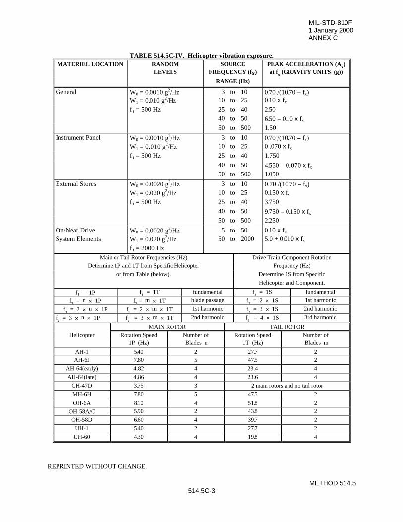
MIL-STD-810F1 January 2000ANNEX C
METHOD 514.5514.5C-3
TABLE 514.5C-IV. Helicopter vibration exposure.MATERIEL LOCATION RANDOM SOURCE PEAK ACCELERATION (Ax)
LEVELS FREQUENCY (fx) at fx (GRAVITY UNITS (g))
RANGE (Hz)
General W0 = 0. 0010 g2/Hz 3 to 10 0. 70 /(10. 70 − fx)W1 = 0. 010 g2/Hz 10 to 25 0. 10 x fx
f t = 500 Hz 25 to 40 2. 50
40 to 50 6. 50 − 0.10 x fx
50 to 500 1. 50
Instrument Panel W0 = 0. 0010 g2/Hz 3 to 10 0. 70 /(10. 70 − fx)W1 = 0. 010 g2/Hz 10 to 25 0 . 070 x fx
f t = 500 Hz 25 to 40 1. 750
40 to 50 4. 550 − 0. 070 x fx
50 to 500 1. 050
External Stores W0 = 0. 0020 g2/Hz 3 to 10 0. 70 /(10. 70 − fx)W1 = 0. 020 g2/Hz 10 to 25 0. 150 x fx
f t = 500 Hz 25 to 40 3. 750
40 to 50 9. 750 − 0. 150 x fx
50 to 500 2. 250
On/Near Drive W0 = 0. 0020 g2/Hz 5 to 50 0. 10 x fx
System Elements W1 = 0. 020 g2/Hz 50 to 2000 5. 0 + 0. 010 x fx
f t = 2000 HzMain or Tail Rotor Frequencies (Hz) Drive Train Component Rotation
Determine 1P and 1T from Specific Helicopter Frequency (Hz)
or from Table (below). Determine 1S from Specific
Helicopter and Component.
f1 = 1P f1 = 1T fundamental f
1 = 1S fundamental
f2 = n × 1P f
2 = m × 1T blade passage f
2 = 2 × 1S 1st harmonic
f3 = 2 × n × 1P f
3 = 2 × m × 1T 1st harmonic f
3 = 3 × 1S 2nd harmonic
f4 = 3 × n × 1P f
4 = 3 × m × 1T 2nd harmonic f
4 = 4 × 1S 3rd harmonic
MAIN ROTOR TAIL ROTORHelicopter Rotation Speed Number of Rotation Speed Number of
1P (Hz) Blades n 1T (Hz) Blades m
AH-1 5.40 2 27. 7 2AH-6J 7. 80 5 47. 5 2
AH-64(early) 4.82 4 23.4 4
AH-64(late) 4.86 4 23.6 4
CH-47D 3. 75 3 2 main rotors and no tail rotor
MH-6H 7. 80 5 47. 5 2
OH-6A 8.10 4 51. 8 2
OH-58A/C 5. 90 2 43. 8 2
OH-58D 6. 60 4 39. 7 2
UH-1 5. 40 2 27. 7 2
UH-60 4. 30 4 19. 8 4
REPRINTED WITHOUT CHANGE.
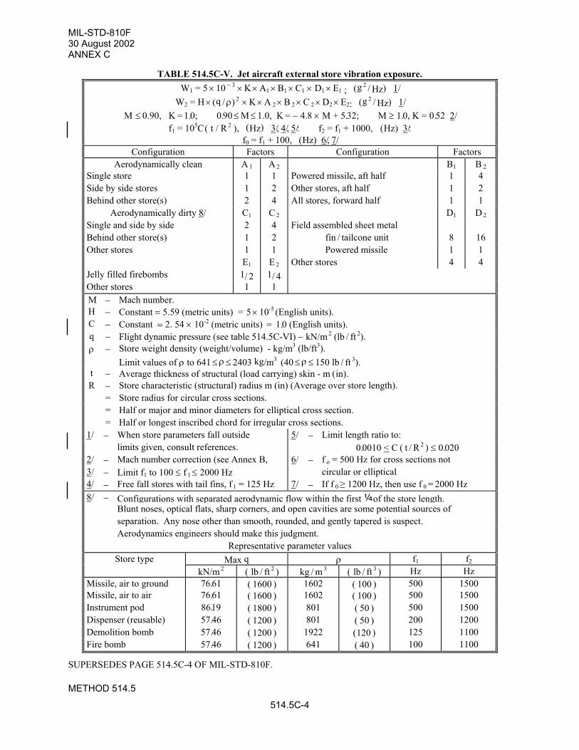
MIL-STD-810F30 August 2002ANNEX C
METHOD 514.5
514.5C-4
TABLE 514.5C-V. Jet aircraft external store vibration exposure.W1 = 5 × 10 − 3 × K × A1 × B1 × C1 × D1 × E1 ; (g
2 / Hz) 1/
W2 = H × (q / ρ) 2 × K × A 2 × B 2 × C 2 × D2 × E2: (g
2 / Hz) 1/
M ≤ 0.90, K = 1. 0; 0. 90 ≤ M ≤ 1.0, K = − 4. 8 × M + 5. 32; M ≥ 1. 0, K = 0. 52 2/f1 = 105C ( t / R
2 ), (Hz) 3/, 4/, 5/: f2 = f1 + 1000, (Hz) 3/:f0 = f1 + 100, (Hz) 6/, 7/
Configuration Factors Configuration FactorsAerodynamically clean A 1 A 2 B1 B 2
Single store 1 1 Powered missile, aft half 1 4Side by side stores 1 2 Other stores, aft half 1 2Behind other store(s) 2 4 All stores, forward half 1 1
Aerodynamically dirty 8/ C1 C 2 D1 D 2
Single and side by side 2 4 Field assembled sheet metalBehind other store(s) 1 2 fin / tailcone unit 8 16Other stores 1 1 Powered missile 1 1
E1 E 2 Other stores 4 4Jelly filled firebombs 1/ 2 1/ 4Other stores 1 1M − Mach number.H − Constant = 5.59 (metric units) = 5 × 10⁻⁵
(English units).C − Constant = 2. 54 × 10-2 (metric units) = 1. 0 (English units).q − Flight dynamic pressure (see table 514.5C-VI) − kN/m
2 (lb / ft 2).
ρ − Store weight density (weight/volume) - kg/m3 (lb/ft3).Limit values of ρ to 641 ≤ ρ ≤ 2403 kg/m3 (40 ≤ ρ ≤ 150 lb / ft 3).
t − Average thickness of structural (load carrying) skin - m (in).R − Store characteristic (structural) radius m (in) (Average over store length).
= Store radius for circular cross sections.= Half or major and minor diameters for elliptical cross section.= Half or longest inscribed chord for irregular cross sections.
1/ − When store parameters fall outside 5/ − Limit length ratio to:limits given, consult references. 0. 0010 < C ( t / R
2 ) ≤ 0. 0202/ − Mach number correction (see Annex B, 6/ − f o = 500 Hz for cross sections not3/ − Limit f1 to 100 ≤ f 1 ≤ 2000 Hz circular or elliptical4/ − Free fall stores with tail fins, f 1 = 125 Hz 7/ − If f 0 ≥ 1200 Hz, then use f 0 = 2000 Hz8/ − Configurations with separated aerodynamic flow within the first ¼of the store length.
Blunt noses, optical flats, sharp corners, and open cavities are some potential sources ofseparation. Any nose other than smooth, rounded, and gently tapered is suspect.Aerodynamics engineers should make this judgment.
Representative parameter valuesStore type Max q ρ f1 f2
kN/m 2 ( lb / ft 2 ) kg / m 3 ( lb / ft 3 ) Hz Hz
Missile, air to ground 76. 61 ( 1600 ) 1602 ( 100 ) 500 1500Missile, air to air 76. 61 ( 1600 ) 1602 ( 100 ) 500 1500Instrument pod 86.19 ( 1800 ) 801 ( 50 ) 500 1500Dispenser (reusable) 57. 46 ( 1200 ) 801 ( 50 ) 200 1200Demolition bomb 57. 46 ( 1200 ) 1922 (120 ) 125 1100Fire bomb 57. 46 ( 1200 ) 641 ( 40 ) 100 1100
SUPERSEDES PAGE 514.5C-4 OF MIL-STD-810F.
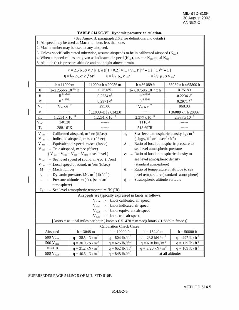
MIL-STD-810F30 August 2002ANNEX C
METHOD 514.5514.5C-5
TABLE 514.5C-VI. Dynamic pressure calculation.(See Annex B, paragraph 2.6.2 for definitions and details)
1. Airspeed may be used at Mach numbers less than one.2. Mach number may be used at any airspeed.3. Unless specifically stated otherwise, assume airspeeds to be in calibrated airspeed (Kcas).4. When airspeed values are given as indicated airspeed (Kias), assume Kias equal Kcas.5. Altitude (h) is pressure altitude and not height above terrain.
q = 2.5 ρ o σ V a2
[( 1/ δ {[ 1 + 0.2 ( V cas / V ao )2 ]
3.5 − 1 } + 1 )
2/7 − 1 ]
q = 1/2 ρ o σ V a2
M2 q = 1/2 ρ o V eas
2 q = 1/2 ρ o σ V tas2
h ≤ 11000 m 11000 ≤ h ≤ 20056 m h ≤ 36 089 ft 36089 ≤ h ≤ 65800 ft
θ 1−2. 2556 x 10 ñ 5 h 0.75189 1− 6. 8750 x 10
- 6 x h 0.75189
δ θ 5. 25610.2234 eφ θ 5.2561
0.2234 eφ
σ θ 4. 25610.2971 eφ θ 4.2561
0.2971 eφ
V a Vao x θ1/2 295.06 Vao x θ
1/2 968.03
φ ------- ( 11000 - h ) / 6342.0 ------ ( 36089 - h )/ 20807ρo 1.2251 x 10
−3 1.2251 x 10 −3 2.377 x 10
−3 2.377 x 10 −3
V ao 340.28 ------ 1116.4 ------To 288.16°K ------ 518.69°R ------
V cas − Calibrated airspeed, m /sec (ft/sec) ρo − Sea level atmospheric density kg / m 3
V ias − Indicated airspeed, m /sec (ft/sec) ( slugs / ft 3 or lb sec
2 / ft
4 )V eas − Equivalent airspeed, m /sec (ft/sec) δ − Ratio of local atmospheric pressure toV tas − True airspeed, m /sec (ft/sec) sea level atmospheric pressure
( V tas = Veas = Vcas = V ias at sea level ) σ − Ratio of local atmospheric density to
V ao − Sea level speed of sound, m /sec (ft/sec) sea level atmospheric densityV ias − Local speed of sound, m /sec (ft/sec) (standard atmosphere)M − Mach number θ − Ratio of temperature at altitude to seaq − Dynamic pressure, kN / m
2 ( lb / ft 2 ) level temperature (standard atmosphere)
h − Pressure altitude, m ( ft ), (standard φ − Stratospheric altitude variableatmosphere)
To − Sea level atmospheric temperature °K (°R)
Airspeeds are typically expressed in knots as follows:Vkcas - knots calibrated air speedVkias - knots indicated air speedVkeas - knots equivalent air speedVktas - knots true air speed
[ knots = nautical miles per hour ( knots x 0.51478 = m /sec)( knots x 1.6889 = ft/sec )]Calculation Check Cases
Airspeed h = 3048 m h = 10000 ft h = 15240 m h = 50000 ft
500 Vkcas q = 38. 5 kN / m 2 q = 804 lb / ft
2 q = 23. 8 kN / m 2 q = 497 lb / ft
2
500 Vktas q = 30. 0 kN / m 2 q = 626 lb / ft
2 q = 6.18 kN / m 2 q = 129 lb / ft
2
M = 0. 8 q = 31. 2 kN / m 2 q = 652 lb / ft
2 q = 5..20 kN / m 2 q = 109 lb / ft
2
500 Vkeas q = 40. 6 kN / m 2 q = 848 lb / ft
2 at all altitudes
SUPERSEDES PAGE 514.5C-5 OF MIL-STD-810F.
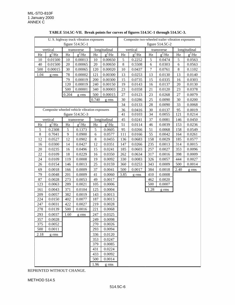
MIL-STD-810F1 January 2000ANNEX C
METHOD 514.5
514.5C-6
TABLE 514.5C-VII. Break points for curves of figures 514.5C-1 through 514.5C-3.
U. S. highway truck vibration exposures Composite two-wheeled trailer vibration exposuresfigure 514.5C-1 figure 514.5C-2
vertical transverse longitudinal vertical transverse longitudinalHz g2/Hz Hz g2/Hz Hz g2/Hz Hz g2/Hz Hz g2/Hz Hz g2/Hz10 0.01500 10 0.00013 10 0.00650 5 0.2252 5 0.0474 5 0.056340 0.01500 20 0.00065 20 0.00650 8 0.5508 6 0.0303 6 0.0563
500 0.00015 30 0.00065 120 0.00020 10 0.0437 7 0.0761 8 0.11021.04 g rms 78 0.00002 121 0.00300 13 0.0253 13 0.0130 13 0.0140
79 0.00019 200 0.00300 15 0.0735 15 0.0335 16 0.0303120 0.00019 240 0.00150 19 0.0143 16 0.0137 20 0.0130500 0.00001 340 0.00003 23 0.0358 21 0.0120 23 0.0378
0.204 g rms 500 0.00015 27 0.0123 23 0.0268 27 0.00790.740 g rms 30 0.0286 25 0.0090 30 0.0200
34 0.0133 28 0.0090 33 0.0068Composite wheeled vehicle vibration exposures 36 0.0416 30 0.0137 95 0.0019
figure 514.5C-3 41 0.0103 34 0.0055 121 0.0214vertical transverse longitudinal 45 0.0241 37 0.0081 146 0.0450
Hz g2/Hz Hz g2/Hz Hz g2/Hz 51 0.0114 46 0.0039 153 0.02365 0.2308 5 0.1373 5 0.0605 95 0.0266 51 0.0068 158 0.05498 0.7041 9 0.0900 6 0.0577 111 0.0166 55 0.0042 164 0.0261
12 0.0527 12 0.0902 8 0.0455 136 0.0683 158 0.0029 185 0.057716 0.0300 14 0.0427 12 0.0351 147 0.0266 235 0.0013 314 0.001520 0.0235 16 0.0496 15 0.0241 185 0.0603 257 0.0027 353 0.009622 0.0109 18 0.0229 16 0.0350 262 0.0634 317 0.0016 398 0.000924 0.0109 119 0.0008 19 0.0092 330 0.0083 326 0.0057 444 0.002726 0.0154 146 0.0013 25 0.0159 360 0.0253 343 0.0009 500 0.001469 0.0018 166 0.0009 37 0.0041 500 0.0017 384 0.0018 2.40 g rms79 0.0048 201 0.0009 41 0.0060 3.85 g rms 410 0.000887 0.0028 273 0.0053 49 0.0017 462 0.0020
123 0.0063 289 0.0021 105 0.0006 500 0.0007161 0.0043 371 0.0104 125 0.0004 1.28 g rms209 0.0057 382 0.0019 143 0.0013224 0.0150 402 0.0077 187 0.0013247 0.0031 422 0.0027 219 0.0028278 0.0139 500 0.0016 221 0.0068293 0.0037 1.60 g rms 247 0.0325357 0.0028 249 0.0098375 0.0052 270 0.0026500 0.0011 293 0.00942.18 g rms 336 0.0120
353 0.0247379 0.0085431 0.0224433 0.0092500 0.00141.96 g rms
REPRINTED WITHOUT CHANGE.
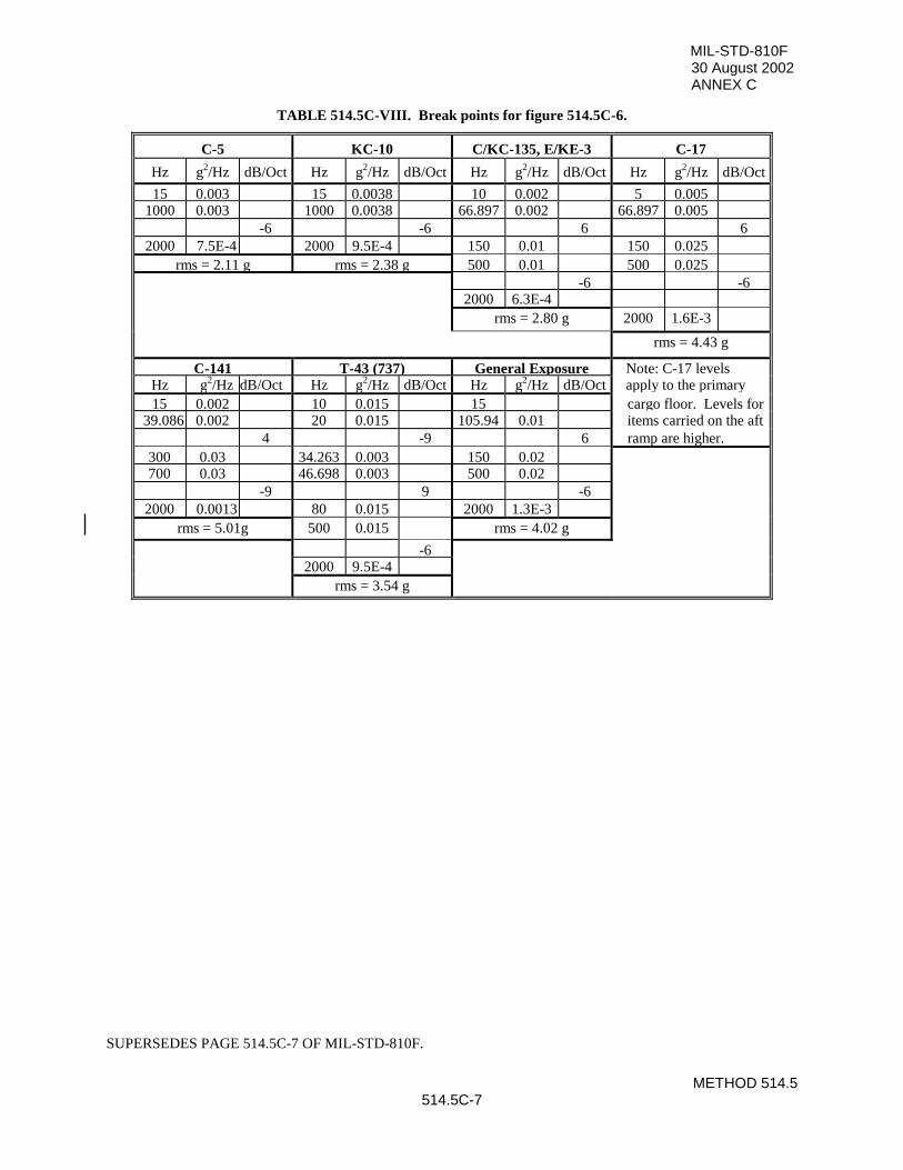
MIL-STD-810F30 August 2002ANNEX C
METHOD 514.5514.5C-7
TABLE 514.5C-VIII. Break points for figure 514.5C-6.
C-5 KC-10 C/KC-135, E/KE-3 C-17
Hz g2/Hz dB/Oct Hz g2/Hz dB/Oct Hz g2/Hz dB/Oct Hz g2/Hz dB/Oct
15 0.003 15 0.0038 10 0.002 5 0.0051000 0.003 1000 0.0038 66.897 0.002 66.897 0.005
-6 -6 6 62000 7.5E-4 2000 9.5E-4 150 0.01 150 0.025
rms = 2.11 g rms = 2.38 g 500 0.01 500 0.025-6 -6
2000 6.3E-4rms = 2.80 g 2000 1.6E-3
rms = 4.43 g
C-141 T-43 (737) General Exposure Note: C-17 levelsHz g2/Hz dB/Oct Hz g2/Hz dB/Oct Hz g2/Hz dB/Oct apply to the primary15 0.002 10 0.015 15 cargo floor. Levels for
39.086 0.002 20 0.015 105.94 0.01 items carried on the aft4 -9 6 ramp are higher.
300 0.03 34.263 0.003 150 0.02700 0.03 46.698 0.003 500 0.02
-9 9 -62000 0.0013 80 0.015 2000 1.3E-3
rms = 5.01g 500 0.015 rms = 4.02 g
-62000 9.5E-4
rms = 3.54 g
SUPERSEDES PAGE 514.5C-7 OF MIL-STD-810F.
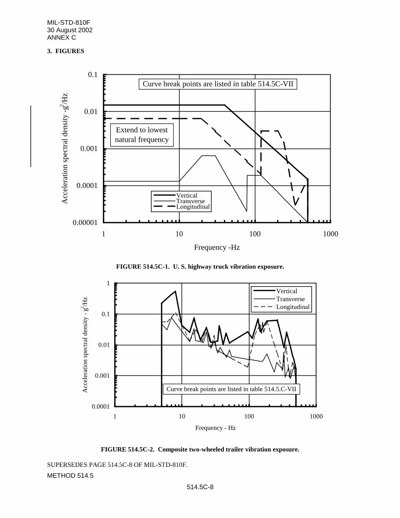
MIL-STD-810F30 August 2002ANNEX C
METHOD 514.5
514.5C-8
3. FIGURES
0.00001
0.0001
0.001
0.01
0.1
1 10 100 1000
Frequency -Hz
Acc
eler
atio
n sp
ectr
al d
ensi
ty -
g2 /Hz
VerticalTransverseLongitudinal
Extend to lowest natural frequency
Curve break points are listed in table 514.5C-VII
FIGURE 514.5C-1. U. S. highway truck vibration exposure.
0.0001
0.001
0.01
0.1
1
1 10 100 1000
Frequency - Hz
Acc
eler
atio
n sp
ectr
al d
ensi
ty -
g2 /H
z
VerticalTransverseLongitudinal
Curve break points are listed in table 514.5.C-VII
FIGURE 514.5C-2. Composite two-wheeled trailer vibration exposure.
SUPERSEDES PAGE 514.5C-8 OF MIL-STD-810F.
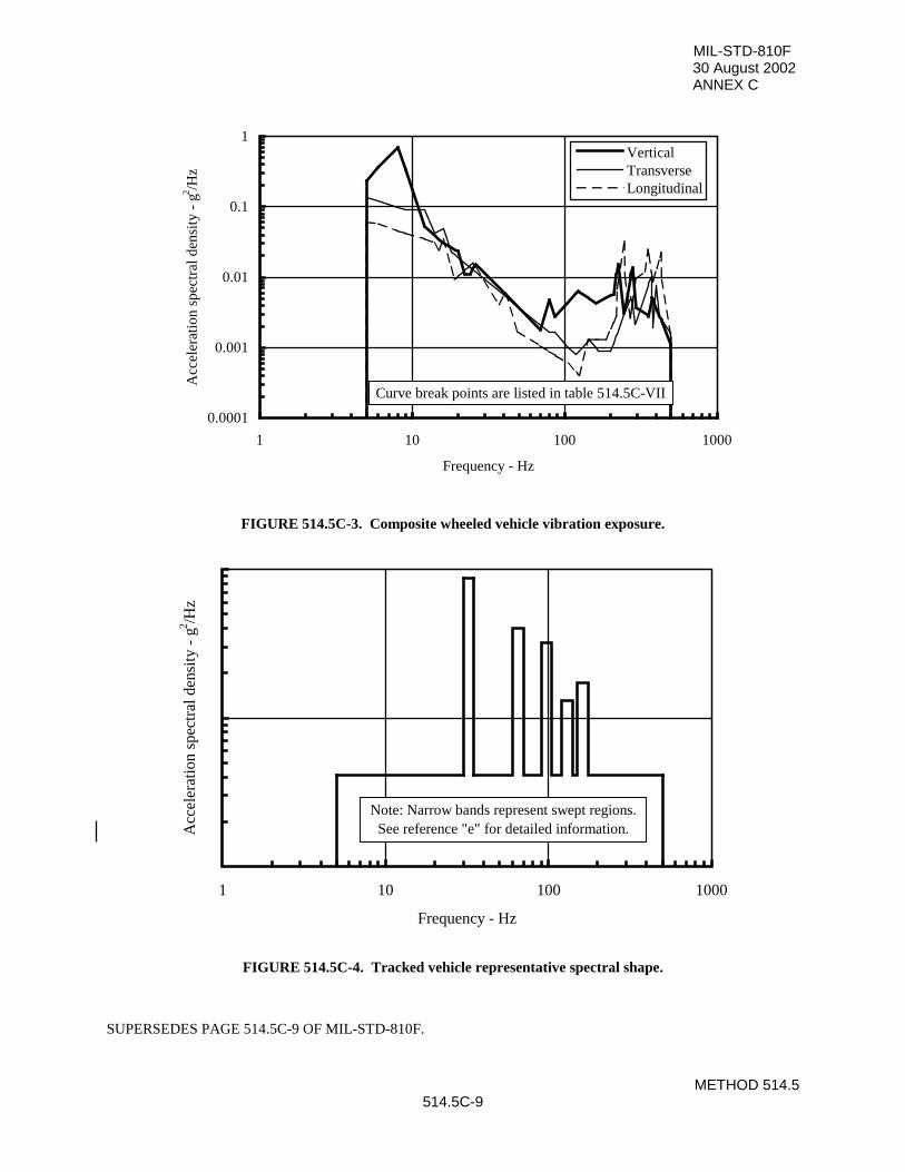
MIL-STD-810F30 August 2002ANNEX C
METHOD 514.5514.5C-9
0.0001
0.001
0.01
0.1
1
1 10 100 1000
Frequency - Hz
Acc
eler
atio
n sp
ectr
al d
ensi
ty -
g2 /H
z
VerticalTransverseLongitudinal
Curve break points are listed in table 514.5C-VII
FIGURE 514.5C-3. Composite wheeled vehicle vibration exposure.
1 10 100 1000
Frequency - Hz
Acc
eler
atio
n sp
ectr
al d
ensi
ty -
g2 /H
z
Note: Narrow bands represent swept regions.See reference "e" for detailed information.
FIGURE 514.5C-4. Tracked vehicle representative spectral shape.
SUPERSEDES PAGE 514.5C-9 OF MIL-STD-810F.
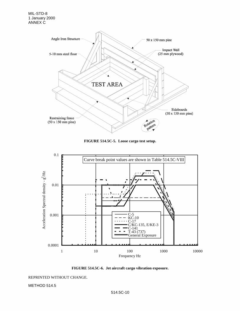
MIL-STD-81 January 2000ANNEX C
METHOD 514.5
514.5C-10
FIGURE 514.5C-5. Loose cargo test setup.
0.0001
0.001
0.01
0.1
1 10 100 1000 10000Frequency Hz
Acc
eler
atio
n S
pect
ral d
ensi
ty -
g2 /H
z
C-5KC-10C-17C/KC-135, E/KE-3C-141T-43 (737)General Exposure
Curve break point values are shown in Table 514.5C-VIII
FIGURE 514.5C-6. Jet aircraft cargo vibration exposure.
REPRINTED WITHOUT CHANGE.
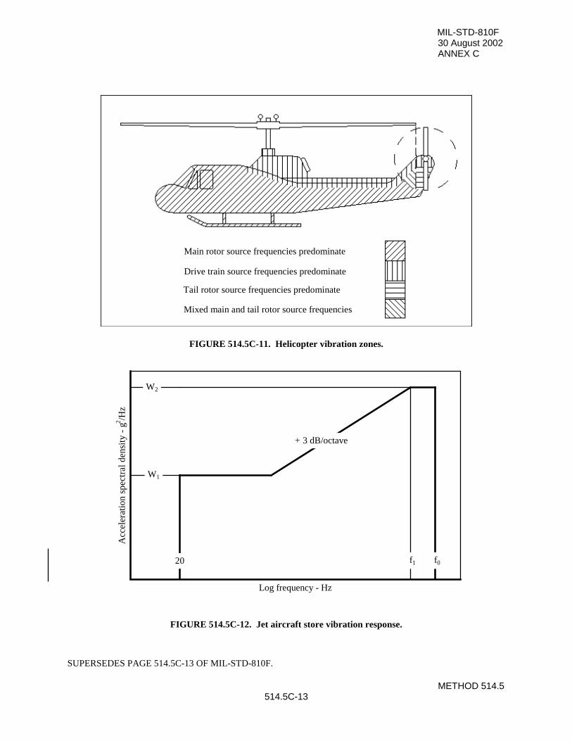
MIL-STD-810F30 August 2002ANNEX C
METHOD 514.5514.5C-13
Main rotor source frequencies predominate
Drive train source frequencies predominate
Tail rotor source frequencies predominate
Mixed main and tail rotor source frequencies
FIGURE 514.5C-11. Helicopter vibration zones.
Log frequency - Hz
Acc
eler
atio
n sp
ectr
al d
ensi
ty -
g2 /H
z
W1
W2
f1 f020
+ 3 dB/octave
FIGURE 514.5C-12. Jet aircraft store vibration response.
SUPERSEDES PAGE 514.5C-13 OF MIL-STD-810F.
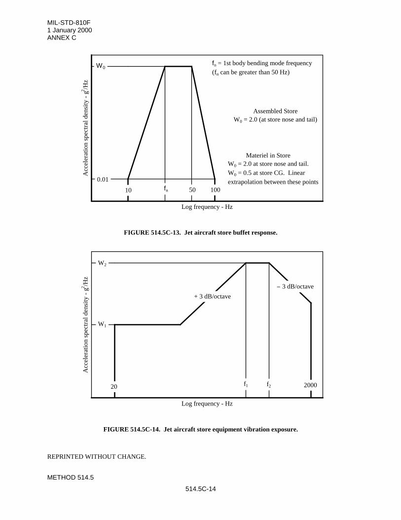
MIL-STD-810F1 January 2000ANNEX C
METHOD 514.5
514.5C-14
Log frequency - Hz
Acc
eler
atio
n sp
ectr
al d
ensi
ty -
g2 /H
z
W0
fn
0.01
10 50 100
fn = 1st body bending mode frequency(fn can be greater than 50 Hz)
Assembled StoreW0 = 2.0 (at store nose and tail)
Materiel in StoreW0 = 2.0 at store nose and tail. W0 = 0.5 at store CG. Linear extrapolation between these points
FIGURE 514.5C-13. Jet aircraft store buffet response.
Log frequency - Hz
Acc
eler
atio
n sp
ectr
al d
ensi
ty -
g2 /H
z
W1
W2
20 f1 f2 2000
+ 3 dB/octave
− 3 dB/octave
FIGURE 514.5C-14. Jet aircraft store equipment vibration exposure.
REPRINTED WITHOUT CHANGE.
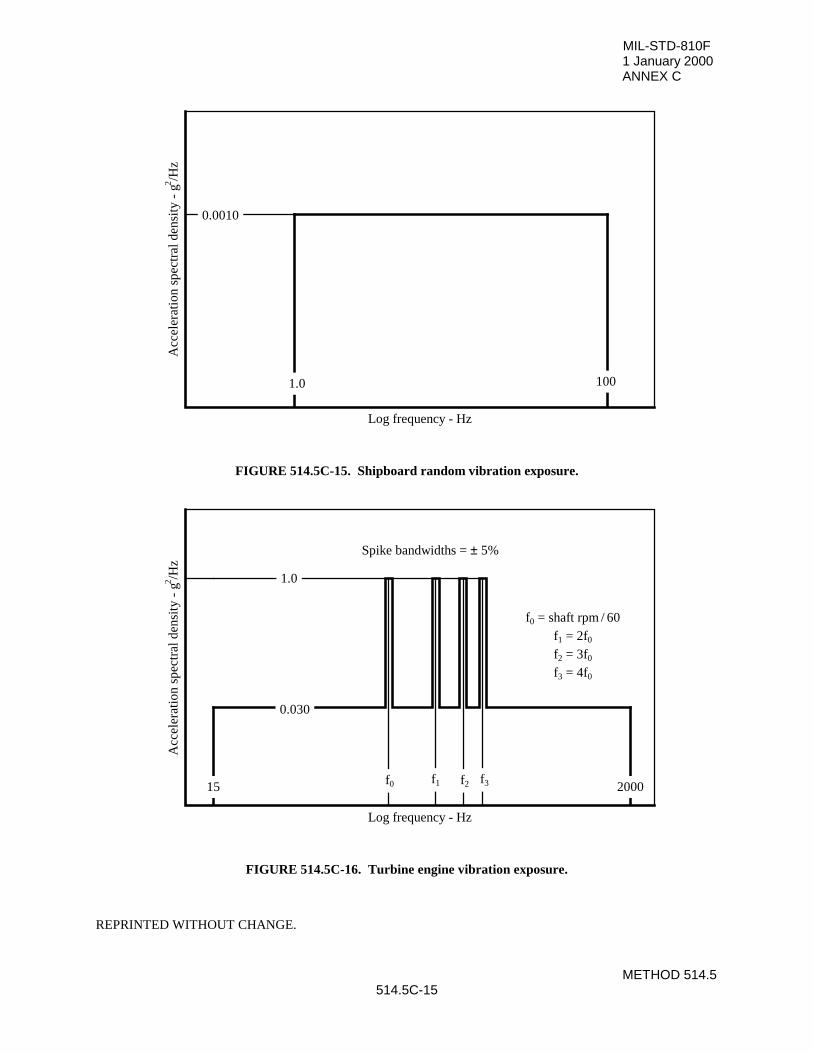
MIL-STD-810F1 January 2000ANNEX C
METHOD 514.5514.5C-15
Log frequency - Hz
Acc
eler
atio
n sp
ectr
al d
ensi
ty -
g2 /H
z
0.0010
1.0 100
FIGURE 514.5C-15. Shipboard random vibration exposure.
Log frequency - Hz
Acc
eler
atio
n sp
ectr
al d
ensi
ty -
g2 /H
z
15 2000
0.030
1.0
f0 f1 f2 f3
Spike bandwidths = ± 5%
f0 = shaft rpm / 60f1 = 2f0
f2 = 3f0
f3 = 4f0
FIGURE 514.5C-16. Turbine engine vibration exposure.
REPRINTED WITHOUT CHANGE.
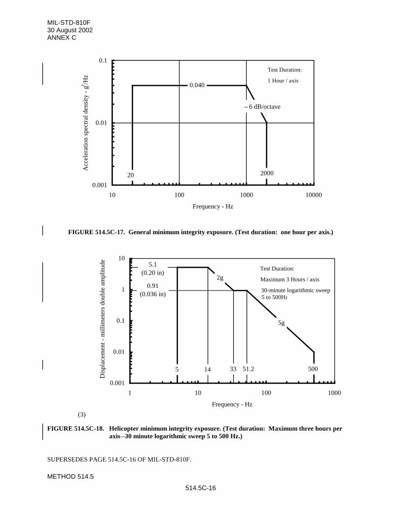
MIL-STD-810F30 August 2002ANNEX C
METHOD 514.5
514.5C-16
0.001
0.01
0.1
10 100 1000 10000
Frequency - Hz
Acc
eler
atio
n sp
ectr
al d
ensi
ty -
g2 /H
z
20 2000
0.040
− 6 dB/octave
FIGURE 514.5C-17. General minimum integrity exposure. (Test duration: one hour per axis.)
(3)
0.001
0.01
0.1
1
10
1 10 100 1000
Frequency - Hz
Dis
plac
emen
t - m
illi
met
ers
doub
le a
mpl
itud
e
5.1(0.20 in)
0.91(0.036 in)
5 14 33 51.2 500
2g
5g
FIGURE 514.5C-18. Helicopter minimum integrity exposure. (Test duration: Maximum three hours peraxis—30 minute logarithmic sweep 5 to 500 Hz.)
SUPERSEDES PAGE 514.5C-16 OF MIL-STD-810F.
Test Duration:
Maximum 3 Hours / axis
30-minute logarithmic sweep5 to 500Hzz
Test Duration:
1 Hour / axis
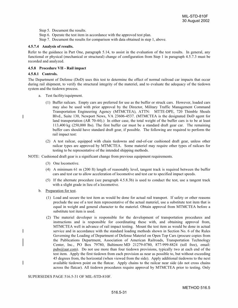
MIL-STD-810F30 August 2002
METHOD 516.5516.5-31
Step 5. Document the results.Step 6. Operate the test item in accordance with the approved test plan.Step 7. Document the results for comparison with data obtained in step 1, above.
4.5.7.4 Analysis of results. Refer to the guidance in Part One, paragraph 5.14, to assist in the evaluation of the test results. In general, anyfunctional or physical (mechanical or structural) change of configuration from Step 1 in paragraph 4.5.7.3 must berecorded and analyzed.
4.5.8 Procedure VII - Rail impact4.5.8.1 Controls. The Department of Defense (DoD) uses this test to determine the effect of normal railroad car impacts that occurduring rail shipment, to verify the structural integrity of the materiel, and to evaluate the adequacy of the tiedownsystem and the tiedown process.
a. Test facility/equipment.
(1) Buffer railcars. Empty cars are preferred for use as the buffer or struck cars. However, loaded carsmay also be used with prior approval by the Director, Military Traffic Management CommandTransportation Engineering Agency (MTMCTEA), ATTN: MTTE-DPE, 720 Thimble ShoalsBlvd., Suite 130, Newport News, VA 23606-4537. (MTMCTEA is the designated DoD agent forland transportation (AR 70-44).) In either case, the total weight of the buffer cars is to be at least113,400 kg (250,000 lbs). The first buffer car must be a standard draft gear car. The remainingbuffer cars should have standard draft gear, if possible. The following are required to perform therail impact test:
(2) A test railcar, equipped with chain tiedowns and end-of-car cushioned draft gear, unless otherrailcar types are approved by MTMCTEA. Some materiel may require other types of railcars fortesting to be representative of the intended shipping methods.
NOTE: Cushioned draft gear is a significant change from previous equipment requirements.
(3) One locomotive.(4) A minimum 61 m (200 ft) length of reasonably level, tangent track is required between the buffer
cars and test car to allow acceleration of locomotive and test car to specified impact speeds.(5) If the alternate procedure (see paragraph 4.5.8.3b) is used to conduct the test, use a tangent track
with a slight grade in lieu of a locomotive.b. Preparation for test.
(1) Load and secure the test item as would be done for actual rail transport. If safety or other reasonspreclude the use of a test item representative of the actual materiel, use a substitute test item that isequal in weight and general character to the materiel. Obtain approval from MTMCTEA before asubstitute test item is used.
(2) The materiel developer is responsible for the development of transportation procedures andinstructions and is responsible for coordinating these with, and obtaining approval from,MTMCTEA well in advance of rail impact testing. Mount the test item as would be done in actualservice and in accordance with the standard loading methods shown in Section No. 6 of the RulesGoverning the Loading of Department of Defense Materiel on Open Top Cars (procure copies fromthe Publications Department, Association of American Railroads, Transportation TechnologyCenter, Inc., PO Box 79780, Baltimore MD 21279-0780, 877-999-8824 (toll free), email:[email protected]). Do not use more than four tiedown provisions, typically two at each end of thetest item. Apply the first tiedown from each provision as near as possible to, but without exceeding45 degrees from, the horizontal (when viewed from the side). Apply additional tiedowns to the nextavailable tiedown point on the flatcar. Apply chains to the railcar near side (do not cross chainsacross the flatcar). All tiedown procedures require approval by MTMCTEA prior to testing. Only
SUPERSEDES PAGE 516.5-31 OF MIL-STD-810F.
MIL-STD-810F30 August 2002
METHOD 516.5516.5-32
use an arrangement of the test item and its tiedown to be tested that is identical to that proposed orapproved by MTMCTEA.
(3) Unless otherwise specified in the transportability requirements for the materiel, perform the test withthe test item at its maximum gross weight (fully loaded) rating.
c. Test setup.
(1) Buffer cars must have their air and hand brakes set. This provides a more conservative test. Carsmust be bunched to compress all slack and cushioning in the couplings, if any. The struck end offirst buffer car must have standard draft gear.
(2) Locate the test car between the buffer cars and the locomotive.(3) Install one of the following timing devices (or equivalent) to obtain the impact speed of the test car.
(a) An electric timer capable of measuring within 0.16 km/h (+0.1 mph): Place the switch contactson the track in accordance with manufacturer's instructions.
(b) A stop watch and torpedoes: when used, measure the torpedo locations. Place the first torpedobeyond the face of the knuckle on the first buffer car and located one foot more than thedistance between the leading axle and knuckle face on the test car. Place the second torpedo 6.7m (22 ft) along the track from the first torpedo. The relationship of time lapse versus speed fortravel of a distance of 6.7 m (22 ft) is shown in table 516.5-VIII.
(c) Radar: To obtain an accurate speed, position the operator of the radar in line with the directionof impact or as otherwise recommended by the radar manufacturer.
(4) Photograph the test setup including any securement items. This may be a valuable tool if there isany subsequent failure of the items of securement.
4.5.8.2 Test tolerances.Ensure test tolerances are in accordance with tolerances specified in paragraphs 4.5.8.1 and 4.5.8.3, and in the testplan.
4.5.8.3 Procedure VII.a. General considerations for main procedure.
(1) Brief the train crew on the procedure. Delegate one person to advise the appropriate member of thetrain crew when moves are to be made. Instruct all participants and observers to take precautionsfor their personal safety and observe safety practices of the carrier and/or company conducting thetest. If desired, perform a test run without impacting the test item to establish accuracy of speed.
(2) Subject the test item to four impacts, the first three of which are in the same direction and at speedsof 6.4, 9.7, and 13 km/h (4, 6, and 8 mph) respectively, with a tolerance of +0.8 km/h (+0.5 mph)for the 6.4 amd 9.7 km/h impacts, and +0.8 -0.0 km/h (+0.5 – 0 mph) for the 13 km/h impacts.
(3) Perform the fourth impact at 13 km/h (+0.8 -0.0 km/h) and impact the opposite end of the test carfrom the first three impacts. If it is not possible to turn the test car because of track layout, this maybe accomplished by running the test item car to the opposite end of the buffer cars and impacting asabove.
(4) If the lading or securement items loosen or fail during the test, photograph and document theseitems. If it appears necessary to adjust the lading or securement items to continue the test, correctthe restraint and restart the test beginning with the 6.4 km/h (4 mph) impact.
(5) Pull the rail car carrying the test item a sufficient distance from the buffer cars. Next, push the testload car toward the buffer cars until the desired speed is obtained, and release it so it rolls freely intothe buffer cars having knuckles positioned for coupling.
(6) If the materiel can be shipped in two orientations (such as lengthwise and crosswise on the rail car),repeat the four impacts for each orientation.
b. General considerations for alternate procedure.SUPERSEDES PAGE 516.5-32 OF MIL-STD-810F.
MIL-STD-810F1 January 2000
METHOD 516.5516.5-33
(1) A section of track can be calibrated using a test car and either radar or another speed-measuringdevice. Release the test car from the designated starting point and allow it to roll freely down theinclined track. For radar, a crew member riding the test car is in radio contact with the radaroperator who reads off the car speed to the rider. For other than radar, follow the same concept.The rider drops markers at track-side to indicate locations at which the desired speeds are obtained.After determining the 8 mph mark, stop the test car by use of the hand brake. Ensure no other carsare present on the test track during the calibration process. Repeat the process two times to ensurethe accuracy of speed locations. If it is difficult for the rider to safely drop the markers and stop thecar using the hand brake, use a free rolling locomotive for the initial calibration when markers aredropped with the locomotive's brakes applied after reaching 8 mph as indicated by radar. Thenrelease the test car from the same starting point and make adjustments in markers if needed prior toimpacting.
(2) After determining speed locations, perform impacts by locating the buffer cars at the proper locationfor desired impact speed and releasing the test car from the designated starting point. This requiresmoving the buffer cars every time a different speed is required.
(3) Use speeds and the direction of impacts as outlined in paragraph 4.5.8.3a.
(4) In lieu of positioning of the buffer cars at various positions on the track, release the test car fromcalibrated positions on the inclined track that correspond to the desired speeds.
(5) If the lading or securement items loosen or fail during the test, photograph and document theseitems. If it appears necessary to adjust the lading or securement items to continue the test, correctthe restraint and restart the test beginning with the 6.4 km/h impact.
c. Additional requirements.
(1) Repeat any impacts that are below the required test speeds. If any readjustment of the lading orreconditioning of the bracing or items of securement is necessary, correct, photograph anddocument the problem(s), correct the restraint and restart the entire test beginning with the 6.4 km/himpact. Accept any impacts above the required test speed providing the test item satisfies therequirements of paragraph 4.5.8.4.
(2) If the tiedown chains or chock blocks become loose during the test, photograph and document theproblem(s). The test director will notify MTMCTEA of the modifications required, and jointlydecide if a retest will be required.
REPRINTED WITHOUT CHANGE.
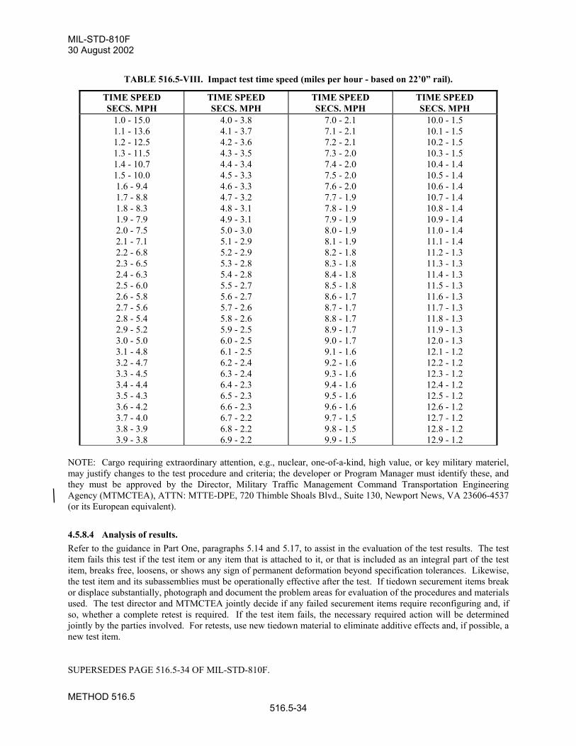
MIL-STD-810F30 August 2002
METHOD 516.5516.5-34
TABLE 516.5-VIII. Impact test time speed (miles per hour - based on 22’0” rail).
TIME SPEEDSECS. MPH
TIME SPEEDSECS. MPH
TIME SPEEDSECS. MPH
TIME SPEEDSECS. MPH
1.0 - 15.01.1 - 13.61.2 - 12.51.3 - 11.51.4 - 10.71.5 - 10.01.6 - 9.41.7 - 8.81.8 - 8.31.9 - 7.92.0 - 7.52.1 - 7.12.2 - 6.82.3 - 6.52.4 - 6.32.5 - 6.02.6 - 5.82.7 - 5.62.8 - 5.42.9 - 5.23.0 - 5.03.1 - 4.83.2 - 4.73.3 - 4.53.4 - 4.43.5 - 4.33.6 - 4.23.7 - 4.03.8 - 3.93.9 - 3.8
4.0 - 3.84.1 - 3.74.2 - 3.64.3 - 3.54.4 - 3.44.5 - 3.34.6 - 3.34.7 - 3.24.8 - 3.14.9 - 3.15.0 - 3.05.1 - 2.95.2 - 2.95.3 - 2.85.4 - 2.85.5 - 2.75.6 - 2.75.7 - 2.65.8 - 2.65.9 - 2.56.0 - 2.56.1 - 2.56.2 - 2.46.3 - 2.46.4 - 2.36.5 - 2.36.6 - 2.36.7 - 2.26.8 - 2.26.9 - 2.2
7.0 - 2.17.1 - 2.17.2 - 2.17.3 - 2.07.4 - 2.07.5 - 2.07.6 - 2.07.7 - 1.97.8 - 1.97.9 - 1.98.0 - 1.98.1 - 1.98.2 - 1.88.3 - 1.88.4 - 1.88.5 - 1.88.6 - 1.78.7 - 1.78.8 - 1.78.9 - 1.79.0 - 1.79.1 - 1.69.2 - 1.69.3 - 1.69.4 - 1.69.5 - 1.69.6 - 1.69.7 - 1.59.8 - 1.59.9 - 1.5
10.0 - 1.510.1 - 1.510.2 - 1.510.3 - 1.510.4 - 1.410.5 - 1.410.6 - 1.410.7 - 1.410.8 - 1.410.9 - 1.411.0 - 1.411.1 - 1.411.2 - 1.311.3 - 1.311.4 - 1.311.5 - 1.311.6 - 1.311.7 - 1.311.8 - 1.311.9 - 1.312.0 - 1.312.1 - 1.212.2 - 1.212.3 - 1.212.4 - 1.212.5 - 1.212.6 - 1.212.7 - 1.212.8 - 1.212.9 - 1.2
NOTE: Cargo requiring extraordinary attention, e.g., nuclear, one-of-a-kind, high value, or key military materiel,may justify changes to the test procedure and criteria; the developer or Program Manager must identify these, andthey must be approved by the Director, Military Traffic Management Command Transportation EngineeringAgency (MTMCTEA), ATTN: MTTE-DPE, 720 Thimble Shoals Blvd., Suite 130, Newport News, VA 23606-4537(or its European equivalent).
4.5.8.4 Analysis of results. Refer to the guidance in Part One, paragraphs 5.14 and 5.17, to assist in the evaluation of the test results. The testitem fails this test if the test item or any item that is attached to it, or that is included as an integral part of the testitem, breaks free, loosens, or shows any sign of permanent deformation beyond specification tolerances. Likewise,the test item and its subassemblies must be operationally effective after the test. If tiedown securement items breakor displace substantially, photograph and document the problem areas for evaluation of the procedures and materialsused. The test director and MTMCTEA jointly decide if any failed securement items require reconfiguring and, ifso, whether a complete retest is required. If the test item fails, the necessary required action will be determinedjointly by the parties involved. For retests, use new tiedown material to eliminate additive effects and, if possible, anew test item.
SUPERSEDES PAGE 516.5-34 OF MIL-STD-810F.
MIL-STD-810F30 August 2002
METHOD 520.2520.2-1
METHOD 520.2
TEMPERATURE, HUMIDITY, VIBRATION, AND ALTITUDENOTE: Tailoring is essential. Select methods, procedures, and parameter levels based on the tailoring processdescribed in Part One, paragraph 4, and Appendix C. Apply the general guidelines for laboratory test methodsdescribed in Part One, paragraph 5 of this standard.
1. SCOPE.
1.1 Purpose. The purpose of this test is to help determine the combined effects of temperature, humidity, vibration, and altitudeon airborne electronic and electro-mechanical materiel with regard to safety, integrity, and performance duringground and flight operations. Some portions of this test may apply to ground vehicles, as well. In such cases,references to altitude considerations do not apply.
1.2 Application.a. Use this method to evaluate materiel likely to be deployed in altitude areas (above ground level) where
temperature, humidity, and vibration may combine to induce failures.
b. Use this method for engineering development, for support of operational testing, for qualification, andfor other similar purposes. This method is primarily intended for actively-powered materiel operated ataltitude; i.e., aircraft, missiles, etc.
c. Use this method to provide an option for use of vibration in combination with the climatic elements, orfor use of the climatic tests in combination with each other. This is often noted throughout the text. Generally, the combined environment test simulates those synergistic environmental effects that occurfor the majority of the deployment life. Environmental stresses that are tested in combination usingMethod 520.2 may replace the individual Methods 500.4, 501.4, 502.4, 507.4, and 514.5, as appropriate.In order to replace the individual test methods successfully, use the tailoring process in paragraph 2.1 toensure the entire method test range is encompassed by Method 520.2.
1.3 Limitations.a. Limit use of this method to evaluating the combined effects of altitude, temperature, humidity, and
vibration.
b. Some procedures permit testing for the effects of one forcing function at a time and stressing materielitems beyond realistic limits. Doing so may reduce or eliminate synergistic or antagonistic effects ofcombined stresses, or may induce failures that would not occur under realistic conditions.
c. This method does not apply to unpowered materiel transported as cargo in an aircraft.
d. The tailored test cycle should not include short duration vibration events or those that occur infrequentlyin the test cycle. These events include firing of on-board guns, extreme aircraft motion, and shock dueto hard landings. Test for these events separately using the appropriate test method.
2. TAILORING GUIDANCE.
2.1 Selecting the Temperature, Humidity, Vibration, and Altitude Method. After examining requirements documents, apply the tailoring process in Part One of this standard to determinewhere these combined forcing functions of temperature, humidity, vibration, and altitude are foreseen in the lifecycle of the materiel in the real world. Use this method only if the proper engineering has been performed such thatthe environmental stresses associated with the individual methods are encompassed by the combined test. Ifappropriate, tailor storage thermal environments into the combined environmental cycle; or, perform them asseparate tests, using the individual test methods. Use the following to aid in selecting this method and placing it insequence with other methods.
SUPERSEDES PAGE 520.2-1 OF MIL-STD-810F.
MIL-STD-810F1 January 2000
METHOD 520.2520.2-2
2.1.1 Effects of combined temperature/humidity/vibration/altitude environments. Temperature, humidity, vibration, and altitude can combine synergistically to produce the following failures. Theexamples are not intended to be comprehensive:
a. Shattering of glass vials and optical materiel. (Temperature/Vibration/Altitude)
b. Binding or loosening of moving parts. (Temperature/Vibration)
c. Separation of constituents. (Temperature/Humidity/Vibration/Altitude)
d. Performance degradation in electronic components due to parameter shifts. (Temperature/Humidity)
e. Electronic optical (fogging) or mechanical failures due to rapid water or frost formation. (Temperature/Humidity)
f. Cracking of solid pellets or grains in explosives. (Temperature/Humidity/Vibration)
g. Differential contraction or expansion of dissimilar materials. (Temperature/Altitude)
h. Deformation or fracture of components. (Temperature/Vibration/Altitude)
i. Cracking of surface coatings. (Temperature/Humidity/ Vibration/Altitude)
j. Leakage of sealed compartments. (Temperature/Vibration//Altitude)
k. Failure due to inadequate heat dissipation. (Temperature/Vibration /Altitude)
2.1.2 Sequence among other methods.a. General. See Part One, paragraph 5.5.
b. Unique to this method. Procedure I is intended to be used before final materiel designs are fixed. Ifdone separately, perform vibration prior to the remaining environments.
2.2 Selecting Procedures. This method includes three temperature, humidity, vibration, and altitude test procedures:
a. Procedure I (Engineering Development);
b. Procedure II (Flight or Operation Support), and
c. Procedure III (Qualification).
2.2.1 Procedure selection considerations.The choice of test procedure is governed by the in-service temperature, humidity, vibration and altitudeenvironments, and the test purpose. In general, the test purpose will drive the selection of test procedure.
2.2.2 Difference among procedures. While all of the procedures cover the same forcing functions, they differ on the basis of the stage of development ofthe materiel being tested, test severity due to acceleration, and scope of the included test profiles.
2.2.2.1 Procedure I - Engineering Development. Use Procedure I to help find defects in a new design while it is still in the development stage. This procedure isaccelerated and failure-oriented, such that it is more likely to uncover design defects compared to using a morebenign procedure. A combined environment test is good for this purpose since it does not require the identificationof which of the four elements of this method is most critical, and allows tailoring of the procedure accordingly. Perform single environment tests in this procedure to verify design margins. This procedure may be accelerated byeliminating the more benign conditions or by using higher stress levels than the item is likely to encounter in thefield. Duration of this test should reflect total expected operating life. This test may focus on specificenvironmental
REPRINTED WITHOUT CHANGE.
MIL-STD-810F30 August 2002
METHOD 520.2520.2-11
4. TEST PROCESS
4.1 Test facility.Use a facility that can provide the required combination of environmental elements. See the guidance for thefacilities for the individual element tests, i.e., methods 500.4, 501.4, 502.4, 507.4, and 514.5. Ensure the facilitysatisfies the requirements of Part One, paragraph 5.
4.2 Controls. Ensure calibration and test tolerance procedures are consistent with the guidance provided in Part One, paragraphs5.3.2 and 5.2, respectively.
4.3 Test interruption.a. General. See Part One, paragraph 5.11 of this standard.
b. Specific to this method.
(1) Undertest interruption. Refer to the interruption guidance for the individual test elements; i.e.,temperature, humidity, low pressure, and vibration.
(2) Overtest interruption. Refer to the interruption guidance for the individual test elements; i.e.,temperature, humidity, low pressure, and vibration.
4.4 Data analysis.Detailed data analysis for verification of the input to the test item and the response monitoring of the test item are tobe in accordance with the test plan.
4.5 Test execution.The following steps, alone or in combination, provide the basis for collecting necessary information concerning thetest item in a combined environment of vibration, temperature, humidity, and altitude. Begin with the firstprocedure specified in the test plan.
4.5.1 Preparation for test
4.5.1.1 Preliminary steps. Before starting the test, review pretest information in the currently approved test plan to determine test details (e.g.,procedures, item configuration, cycles, durations, parameter levels for storage/operation, etc.). (See paragraph 3.1,above.)
4.5.1.2 Qualification test cycle. (Figure 520.2A-3.)Step 1. Ramp to Cold/Dry - With the test item non-operating, ramp the chamber temperature from room
ambient conditions down to the extreme low operating temperature at 5°C/minute or at a maximumrate provided by ECS.
Step 2. Cold/Dry Soak - Allow the test item to soak at this temperature until it has reached thermalstabilization or for 4 hours (whichever is greater). If vibration is to be performed during this step,derive it from a low altitude, high Mach flight condition (combined temperature/vibration may beperformed separately). Ground vehicles would use severe road/field vibration levels.
Step 3. Cold/Dry Warm-Up - Operate the test item at its minimum operating voltage. If supplemental coolingis supplied during this step, tailor cooling parameters for minimum heat removal (e.g., minimumtemperature and minimum flow for air cooling at or above the minimum operating temperature).Maintain this condition for the minimum specified warm-up period.
SUPERSEDES PAGE 520.2-11 OF MIL-STD-810F.
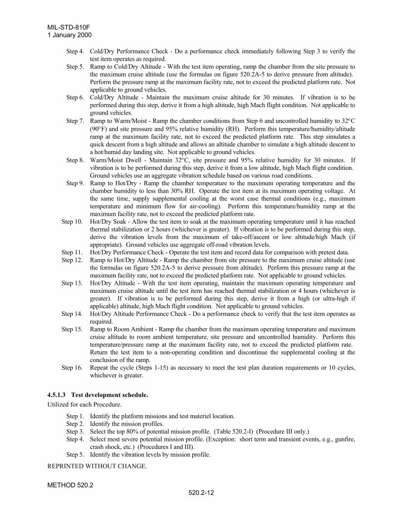
MIL-STD-810F1 January 2000
METHOD 520.2520.2-12
Step 4. Cold/Dry Performance Check - Do a performance check immediately following Step 3 to verify thetest item operates as required.
Step 5. Ramp to Cold/Dry Altitude - With the test item operating, ramp the chamber from the site pressure tothe maximum cruise altitude (use the formulas on figure 520.2A-5 to derive pressure from altitude). Perform the pressure ramp at the maximum facility rate, not to exceed the predicted platform rate. Notapplicable to ground vehicles.
Step 6. Cold/Dry Altitude - Maintain the maximum cruise altitude for 30 minutes. If vibration is to beperformed during this step, derive it from a high altitude, high Mach flight condition. Not applicable toground vehicles.
Step 7. Ramp to Warm/Moist - Ramp the chamber conditions from Step 6 and uncontrolled humidity to 32°C(90°F) and site pressure and 95% relative humidity (RH). Perform this temperature/humidity/altituderamp at the maximum facility rate, not to exceed the predicted platform rate. This step simulates aquick descent from a high altitude and allows an altitude chamber to simulate a high altitude descent toa hot/humid day landing site. Not applicable to ground vehicles.
Step 8. Warm/Moist Dwell - Maintain 32°C, site pressure and 95% relative humidity for 30 minutes. Ifvibration is to be performed during this step, derive it from a low altitude, high Mach flight condition. Ground vehicles use an aggregate vibration schedule based on various road conditions.
Step 9. Ramp to Hot/Dry - Ramp the chamber temperature to the maximum operating temperature and thechamber humidity to less than 30% RH. Operate the test item at its maximum operating voltage. Atthe same time, supply supplemental cooling at the worst case thermal conditions (e.g., maximumtemperature and minimum flow for air-cooling). Perform this temperature/humidity ramp at themaximum facility rate, not to exceed the predicted platform rate.
Step 10. Hot/Dry Soak - Allow the test item to soak at the maximum operating temperature until it has reachedthermal stabilization or 2 hours (whichever is greater). If vibration is to be performed during this step,derive the vibration levels from the maximum of take-off/ascent or low altitude/high Mach (ifappropriate). Ground vehicles use aggregate off-road vibration levels.
Step 11. Hot/Dry Performance Check - Operate the test item and record data for comparison with pretest data.Step 12. Ramp to Hot/Dry Altitude - Ramp the chamber from site pressure to the maximum cruise altitude (use
the formulas on figure 520.2A-5 to derive pressure from altitude). Perform this pressure ramp at themaximum facility rate, not to exceed the predicted platform rate. Not applicable to ground vehicles.
Step 13. Hot/Dry Altitude - With the test item operating, maintain the maximum operating temperature andmaximum cruise altitude until the test item has reached thermal stabilization or 4 hours (whichever isgreater). If vibration is to be performed during this step, derive it from a high (or ultra-high ifapplicable) altitude, high Mach flight condition. Not applicable to ground vehicles.
Step 14. Hot/Dry Altitude Performance Check - Do a performance check to verify that the test item operates asrequired.
Step 15. Ramp to Room Ambient - Ramp the chamber from the maximum operating temperature and maximumcruise altitude to room ambient temperature, site pressure and uncontrolled humidity. Perform thistemperature/pressure ramp at the maximum facility rate, not to exceed the predicted platform rate. Return the test item to a non-operating condition and discontinue the supplemental cooling at theconclusion of the ramp.
Step 16. Repeat the cycle (Steps 1-15) as necessary to meet the test plan duration requirements or 10 cycles,whichever is greater.
4.5.1.3 Test development schedule.Utilized for each Procedure.
Step 1. Identify the platform missions and test materiel location.Step 2. Identify the mission profiles.Step 3. Select the top 80% of potential mission profile. (Table 520.2-I) (Procedure III only.)Step 4. Select most severe potential mission profile. (Exception: short term and transient events, e.g., gunfire,
crash shock, etc.) (Procedures I and III).Step 5. Identify the vibration levels by mission profile.
REPRINTED WITHOUT CHANGE.
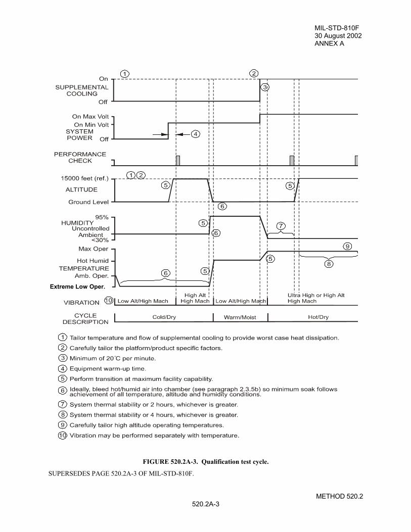
MIL-STD-810F30 August 2002ANNEX A
METHOD 520.2520.2A-3
FIGURE 520.2A-3. Qualification test cycle.
SUPERSEDES PAGE 520.2A-3 OF MIL-STD-810F.
Extreme Low Oper.
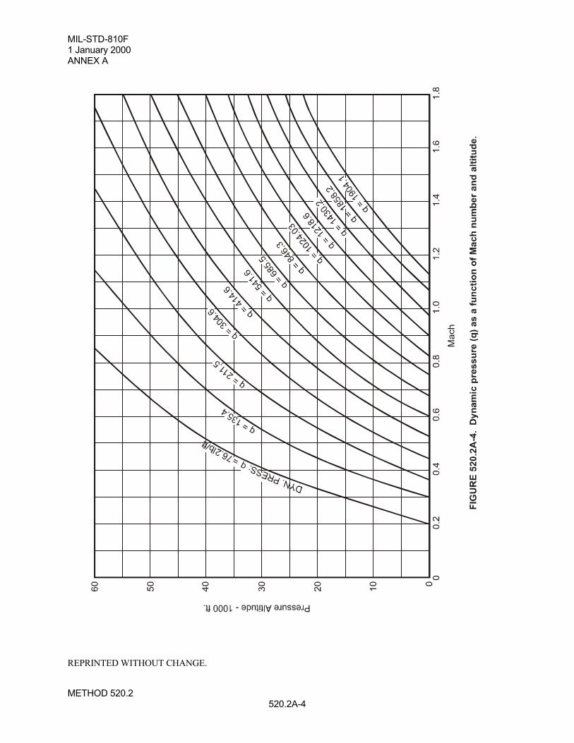
MIL-STD-810F1 January 2000ANNEX A
METHOD 520.2520.2A-4
REPRINTED WITHOUT CHANGE.
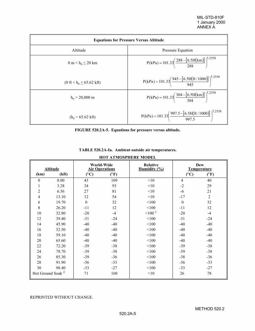
MIL-STD-810F1 January 2000ANNEX A
METHOD 520.2520.2A-5
Equations for Pressure Versus Altitude
Altitude Pressure Equation
0 m < hp < 20 km
(0 ft < hp < 65.62 kft)
( )[ ] 2558.5
288kmH5.628833.101)kPa(P
−
=
( )[ ] 2558.5
9451000/ftH5.694533.101)kPa(P
−
=
hp > 20,000 m
(hp > 65.62 kft)
( )[ ] 2558.5
304kmH5.630433.101)kPa(P
−
=
( )[ ] 2558.5
5.9971000/ftH5.65.99733.101)kPa(P
−
=
FIGURE 520.2A-5. Equations for pressure versus altitude.
TABLE 520.2A-Ia. Ambient outside air temperatures.
HOT ATMOSPHERE MODEL
Altitude(km) (kft)
World-WideAir Operations
(°C) (°F)
RelativeHumidity (%)
DewTemperature
(°C) (°F)0 0.00 43 109 <10 4 401 3.28 34 93 <10 -2 292 6.56 27 81 <10 -6 214 13.10 12 54 <10 -17 26 19.70 0 32 <100 0 328 26.20 -11 12 <100 -11 12
10 32.80 -20 -4 <100 1/ -20 -412 39.40 -31 -24 <100 -31 -2414 45.90 -40 -40 <100 -40 -4016 52.50 -40 -40 <100 -40 -4018 59.10 -40 -40 <100 -40 -4020 65.60 -40 -40 <100 -40 -4022 72.20 -39 -38 <100 -39 -3824 78.70 -39 -38 <100 -39 -3826 85.30 -39 -36 <100 -38 -3628 91.90 -36 -33 <100 -36 -3330 98.40 -33 -27 <100 -33 -27
Hot Ground Soak 2/ 71 160 <10 26 78
REPRINTED WITHOUT CHANGE.
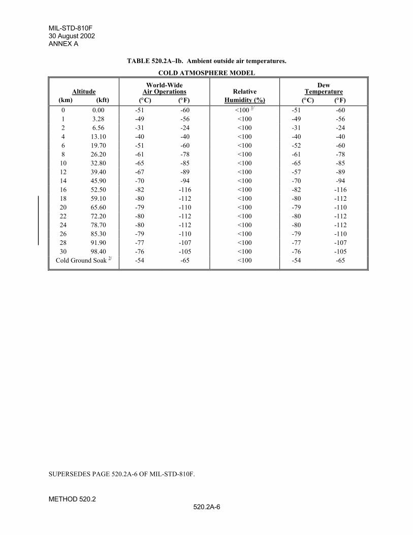
MIL-STD-810F30 August 2002ANNEX A
METHOD 520.2520.2A-6
TABLE 520.2A–Ib. Ambient outside air temperatures.
COLD ATMOSPHERE MODEL
Altitude(km) (kft)
World-WideAir Operations
(°C) (°F)Relative
Humidity (%)
DewTemperature
(°C) (°F)0 0.00 -51 -60 <100 1/ -51 -601 3.28 -49 -56 <100 -49 -562 6.56 -31 -24 <100 -31 -244 13.10 -40 -40 <100 -40 -406 19.70 -51 -60 <100 -52 -608 26.20 -61 -78 <100 -61 -78
10 32.80 -65 -85 <100 -65 -8512 39.40 -67 -89 <100 -57 -8914 45.90 -70 -94 <100 -70 -9416 52.50 -82 -116 <100 -82 -11618 59.10 -80 -112 <100 -80 -11220 65.60 -79 -110 <100 -79 -11022 72.20 -80 -112 <100 -80 -11224 78.70 -80 -112 <100 -80 -11226 85.30 -79 -110 <100 -79 -11028 91.90 -77 -107 <100 -77 -10730 98.40 -76 -105 <100 -76 -105
Cold Ground Soak 2/ -54 -65 <100 -54 -65
SUPERSEDES PAGE 520.2A-6 OF MIL-STD-810F.
MIL-STD-810F30 August 2002
METHOD 522522-3
2. TAILORING GUIDANCE
2.1 Selecting the Ballistic Shock Method.After examining requirements documents and applying the tailoring process in Part One of this standard to determinewhere ballistic shock effects are foreseen in the life cycle of the materiel, use the following to confirm the need forthis method and to place it in sequence with other methods.
2.1.1 Effects of ballistic shock.
In general, ballistic shock has the potential for producing adverse effects on all electronic, mechanical, and electro-mechanical materiel. In general, the level of adverse effects increases with the level and duration of the ballisticshock and decreases with the distance from the source (point or points of impact) of the ballistic shock. Durationsfor ballistic shock that produce material stress waves with wavelengths that correspond with the natural frequencywavelengths of micro electronic components within materiel will enhance adverse effects. Durations for ballisticshock that produce structure response movement that correspond with the low frequency resonances of mechanicaland electro-mechanical materiel will enhance the adverse effects. Examples of problems associated with ballisticshock include:
a. materiel failure as a result of destruction of the structural integrity of micro electronic chips includingtheir mounting configuration;
b. materiel failure as a result of relay chatter;
c. materiel failure as a result of circuit card malfunction, circuit card damage, and electronic connectorfailure. On occasion, circuit card contaminants having the potential to cause short circuits may bedislodged under ballistic shock. Circuit card mounts may be subject to damage from substantial velocitychanges and large displacements.
d. materiel failure as a result of cracks and fracture in crystals, ceramics, epoxies or glass envelopes.
e. materiel failure as a result of sudden velocity change of the structural support of the materiel or theinternal structural configuration of the mechanical or electro-mechanical materiel.
2.1.2 Sequence among other methods.
a. General. See Part One, paragraph 5.5.
b. Unique to this method. Unless otherwise identified in the life cycle profile and, since ballistic shock isnormally experienced in combat and potentially near the end of the life cycle, normally schedule ballisticshock tests late in the test sequence. In general, the ballistic shock tests can be considered independentof the other tests because of their unique and specialized nature.
2.2 Selecting a Procedure.
This method includes five ballistic shock test procedures. See paragraph 2.3.4 for the "default " approach to ballisticshock testing when no field data are available.
a. Procedure I Ballistic Hull and Turret (BH&T), Full Spectrum, Ballistic Shock Qualification.Replication of the shock associated with ballistic impacts on armored vehicles can be accomplished byfiring projectiles at a "Ballistic Hull and Turret " (BH&T) with the materiel mounted inside. Thisprocedure is very expensive and requires that an actual vehicle or prototype be available, as well asappropriate threat munitions. Because of these limitations, a variety of other approaches is oftenpursued. The variety of devices used to simulate ballistic shock is described in reference d of this method.
b. Procedure II Large Scale Ballistic Shock Simulator (LSBSS). Ballistic shock testing of completecomponents over the entire spectrum (10 Hz to 100 kHz) defined in table 522-I and on figure 522-1 canbe accomplished using devices such as the Large Scale Ballistic Shock Simulator (LSBSS) described inreference d. This approach is used for components weighing up to 500 Kg (1100 lbs), and isconsiderably less expensive than the BH&T approach of Procedure I.
c. Procedure III - Limited Spectrum, Light Weight Shock Machine (LWSM). Components weighing lessthan 113.6 kg (250 lbs) and shock mounted to eliminate sensitivity to frequencies above 3 kHz can betested over the spectrum from 10 Hz to 3 kHz of table 522-I and figure 522-1 using a MIL-S-901 LightWeight Shock Machine (LWSM) adjusted for 15 mm (0.59 inch) displacement limits. Use of the LWSMis less expensive than full spectrum simulation, and may be appropriate if the specific test item does not
SUPERSEDES PAGE 522-3 OF MIL-STD-810F.
MIL-STD-810F30 August 2002
METHOD 522522-4
respond to high frequency shock and cannot withstand the excessive low frequency response of the droptable (Procedure V).
d. Procedure IV - Limited Spectrum, Medium Weight Shock Machine (MWSM). Components weighingless than 2273 kg (5000 lbs) and not sensitive to frequencies above 1 kHz can be tested over thespectrum from 10 Hz to 1 kHz of table 522-I and figure 522-1 using a MIL-S-901 Medium WeightShock Machine (MWSM) adjusted for 15 mm (0.59 inch) displacement limits. Use of the MWSW maybe appropriate for heavy components and subsystems that are shock mounted and/or are not sensitive tohigh frequencies.
e. Procedure V - Drop Table. Light weight components (typically less than 18 kg (40 lbs)) which are shockmounted can often be evaluated for ballistic shock sensitivity at frequencies up to 500 Hz using a droptable. This technique often results in overtest at the low frequencies. The vast majority of componentsthat need shock protection on an armored vehicle can be readily shock mounted. The commonlyavailable drop test machine is the least expensive and most accessible test technique. The shock tableproduces a half-sine acceleration pulse that differs significantly from ballistic shock. The response ofmateriel on shock mounts can be enveloped quite well with a half-sine acceleration pulse if an overtest atlow frequencies and an undertest at high frequencies is acceptable. Historically, these shortcomings havebeen acceptable for the majority of ballistic shock qualification testing.
NOTES:Related shock tests:1. High Impact / Shipboard Equipment. Perform shock tests for shipboard equipment in accordance with MIL-S-
901. The tests of MIL-S-901 are tailorable through the design of the fixture that attaches the test item to theshock machine. Ensure the fixture is as similar to the mounting method used in the actual use environment. Highimpact shocks for Army armored combat vehicles should be tested using Method 522, "Ballistic Shock."
2. Fuzes and Fuze Components. Perform shock tests for safety and operation of fuzes and fuze components inaccordance with MIL-STD-331.
3. Combined Temperature and Shock Tests. Perform shock tests at ambient conditions unless a high or lowtemperature shock test is required.)
2.2.1 Procedure selection considerations.Based on the test data requirements, determine which test procedure is applicable. In most cases, the selection of theprocedure will be dictated by the actual materiel configuration, carefully noting any gross structural discontinuitiesthat may serve to mitigate the effects of the ballistic shock on the materiel. In some cases, the selection of theprocedure will be driven by test practicality. Consider all ballistic shock environments anticipated for the materielduring its life cycle, both in its logistic and operational modes. When selecting procedures, consider:
a. The operational purpose of the materiel. From the requirements documents, determine the functions tobe performed by the materiel either during or after exposure to the ballistic shock environment.
b. The natural exposure circumstances for ballistic shock. The natural exposure circumstances for ballisticshock are based on well-selected scenarios from past experience and the chances of the occurrence ofsuch scenarios. For example, if an armored vehicle is subject to a mine blast, a number of assumptionsmust be made in order to select an appropriate test for the ballistic shock procedure. In particular, thesize of the mine, the location of major pressure wave impact, the location of the materiel relative to theimpact ì point,î etc. If the armored vehicle is subject to non-penetrating projectile impact, the energyinput configuration will be different from that of the mine, as will be the effects of the ballistic shock onthe materiel within the armored vehicle. In any case, condition each scenario to estimate the materielresponse as a function of amplitude level and frequency content. It will then be necessary to decide towhich scenarios to test and which testing is most critical. Some scenario responses may " envelope"others, which may reduce the need for certain testing such as road, rail, gunfiring, etc. In test planning,do not break up any measured or predicted response to ballistic shock into separate amplitude and/orfrequency ranges utilizing different tests to satisfy one procedure.
c. Required data. The test data required to determine whether the operational purpose of the materiel hasbeen met.
d. Procedure sequence. Refer to paragraph 2.1.2.
SUPERSEDES PAGE 522-4 OF MIL-STD-810F.