Embed Size (px)
Citation preview

Cette publication est également disponible en français.
Ministry ofNaturalResourcesOntarioLyn McLeodMinister
Environmental Guidelines ForAccess Roads and Water Crossings
©1990, Queen's Printer for Ontario
Printed in Ontario, Canada
Single copies of this publication are available for $5.25 from the address notedbelow.
Current publications of the Ontario Ministry of Natural Resources, and price lists, areobtainable through the Ministry of Natural Resources Public Information Centre,Room 1640, Whitney Block, 99 Wellesley St. West, Toronto, Ontario M7A IW3(personal shopping and mail orders).
Telephone inquiries about ministry programs and services should be directed to thePublic Information Centres:Fisheries/Fishing Licence Sales (416) 965-7883Wildlife/Hunting Licence Sales 965-4251Provincial Parks 965-3081Forestry/Lands 965-9751Aerial Photographs 965-1123Maps 965-6511Minerals 965-1348
Other government publications are available from Publications Ontario, Main Floor,880 Bay St., Toronto. For mail orders write MGS Publications Services Section, 5thFloor, 880 Bay St., Toronto, Ontario M7A IN8.
Cover Photo - The Brightsand River bridge,built by Canadian Pacific Forest ProductsLimited near Thunder Bay, illustrates the useof good design and construction practices tominimize environmental changes.
Cheques or money orders should be made payable to the Treasurer of Ontario, andpayment must accompany order.
This paper containsrecycled materials
1
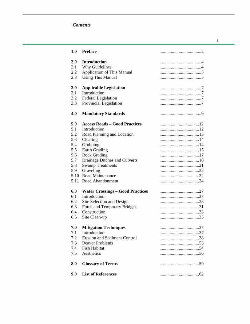
1.0 Preface .....................................2
2.0 Introduction .....................................42.1 Why Guidelines .....................................42.2 Application of This Manual .....................................52.3 Using This Manual .....................................5
3.0 Applicable Legislation .....................................73.1 Introduction .....................................73.2 Federal Legislation .....................................73.3 Provincial Legislation .....................................7
4.0 Mandatory Standards .....................................9
5.0 Access Roads – Good Practices ...................................125.1 Introduction ...................................125.2 Road Planning and Location ...................................135.3 Clearing ...................................145.4 Grubbing ...................................145.5 Earth Grading ...................................155.6 Rock Grading ...................................175.7 Drainage Ditches and Culverts ...................................185.8 Swamp Treatments ...................................215.9 Graveling ...................................225.10 Road Maintenance ...................................225.11 Road Abandonment ...................................24
6.0 Water Crossings – Good Practices ...................................276.1 Introduction ...................................276.2 Site Selection and Design ...................................286.3 Fords and Temporary Bridges ...................................316.4 Construction ...................................336.5 Site Clean-up ...................................35
7.0 Mitigation Techniques ...................................377.1 Introduction ...................................377.2 Erosion and Sediment Control ...................................387.3 Beaver Problems ...................................537.4 Fish Habitat ...................................547.5 Aesthetics ...................................56
8.0 Glossary of Terms ...................................59
9.0 List of References ...................................62
Contents

2
1.0 Preface
This manual provides a collection ofguidelines for those involved with accessroads on Crown land in Ontario. It willassist them in carrying out their projectswith a minimum of disturbance to thenatural environment.
These guidelines were preparedfollowing an extensive review of guide-lines used for similar purposes inother jurisdictions. Section 9 contains apartial list of these other publications.
A technical advisory groupassisted in developing the manual's finaltext.
Organizations represented within theadvisory group included variousdisciplines within the Ministry, theOntario Forest Industries Association,the Ontario Lumber ManufacturersAssociation and the Ontario Ministry ofthe Environment.
The group's participation ensured thepublication reflects the knowledge andfield observations of experienced peoplefrom a cross-section of public andprivate sector organizations that have aninterest in access roads and watercrossings in Ontario.
3
1.0 Preface
Outside Participants:Ministry of Natural Resources:
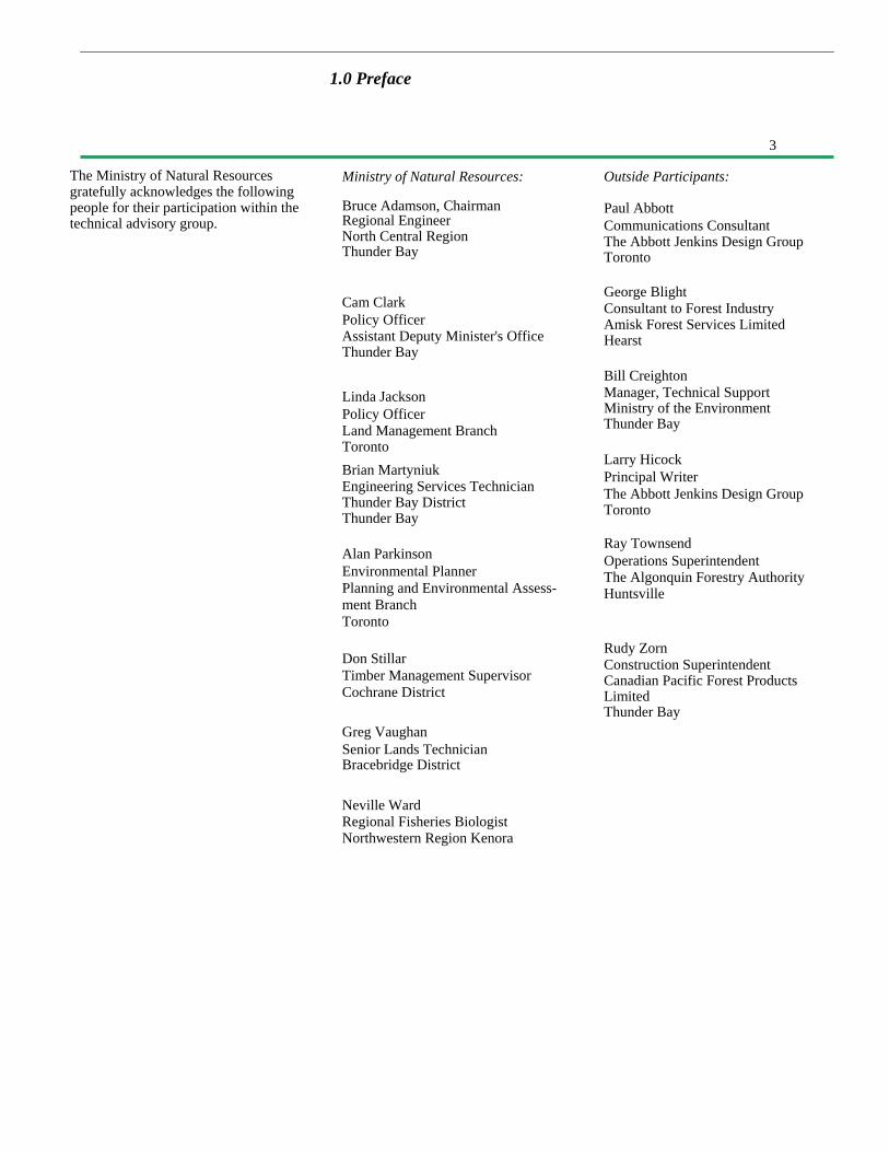
Bruce Adamson, ChairmanRegional EngineerNorth Central RegionThunder Bay
Cam ClarkPolicy OfficerAssistant Deputy Minister's OfficeThunder Bay
Linda JacksonPolicy OfficerLand Management BranchTorontoBrian MartyniukEngineering Services TechnicianThunder Bay DistrictThunder Bay
Alan ParkinsonEnvironmental PlannerPlanning and Environmental Assess-ment BranchToronto
Don StillarTimber Management SupervisorCochrane District
Greg VaughanSenior Lands TechnicianBracebridge District
Neville WardRegional Fisheries BiologistNorthwestern Region Kenora
George BlightConsultant to Forest IndustryAmisk Forest Services LimitedHearst
Bill CreightonManager, Technical SupportMinistry of the EnvironmentThunder Bay
Larry HicockPrincipal WriterThe Abbott Jenkins Design GroupToronto
Ray TownsendOperations SuperintendentThe Algonquin Forestry AuthorityHuntsville
Rudy ZornConstruction SuperintendentCanadian Pacific Forest ProductsLimitedThunder Bay
The Ministry of Natural Resourcesgratefully acknowledges the followingpeople for their participation within thetechnical advisory group.
Paul AbbottCommunications ConsultantThe Abbott Jenkins Design GroupToronto
4
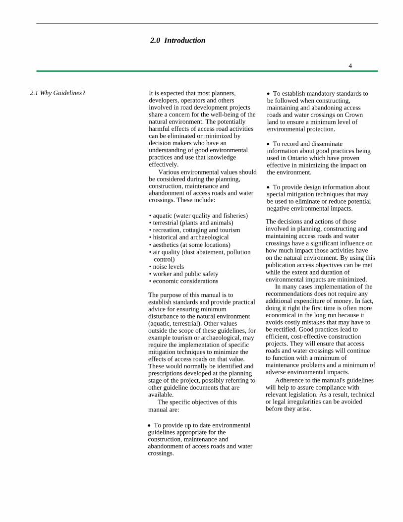
2.1 Why Guidelines? It is expected that most planners,developers, operators and othersinvolved in road development projectsshare a concern for the well-being of thenatural environment. The potentiallyharmful effects of access road activitiescan be eliminated or minimized bydecision makers who have anunderstanding of good environmentalpractices and use that knowledgeeffectively.
Various environmental values shouldbe considered during the planning,construction, maintenance andabandonment of access roads and watercrossings. These include:
• aquatic (water quality and fisheries)• terrestrial (plants and animals)• recreation, cottaging and tourism• historical and archaeological• aesthetics (at some locations)• air quality (dust abatement, pollution
control)• noise levels• worker and public safety• economic considerations
The purpose of this manual is toestablish standards and provide practicaladvice for ensuring minimumdisturbance to the natural environment(aquatic, terrestrial). Other valuesoutside the scope of these guidelines, forexample tourism or archaeological, mayrequire the implementation of specificmitigation techniques to minimize theeffects of access roads on that value.These would normally be identified andprescriptions developed at the planningstage of the project, possibly referring toother guideline documents that areavailable.
The specific objectives of thismanual are:
• To provide up to date environmentalguidelines appropriate for theconstruction, maintenance andabandonment of access roads and watercrossings.
• To establish mandatory standards tobe followed when constructing,maintaining and abandoning accessroads and water crossings on Crownland to ensure a minimum level ofenvironmental protection.
• To record and disseminateinformation about good practices beingused in Ontario which have proveneffective in minimizing the impact onthe environment.
• To provide design information aboutspecial mitigation techniques that maybe used to eliminate or reduce potentialnegative environmental impacts.
The decisions and actions of thoseinvolved in planning, constructing andmaintaining access roads and watercrossings have a significant influence onhow much impact those activities haveon the natural environment. By using thispublication access objectives can be metwhile the extent and duration ofenvironmental impacts are minimized.
In many cases implementation of therecommendations does not require anyadditional expenditure of money. In fact,doing it right the first time is often moreeconomical in the long run because itavoids costly mistakes that may have tobe rectified. Good practices lead toefficient, cost-effective constructionprojects. They will ensure that accessroads and water crossings will continueto function with a minimum ofmaintenance problems and a minimum ofadverse environmental impacts.
Adherence to the manual's guidelineswill help to assure compliance withrelevant legislation. As a result, technicalor legal irregularities can be avoidedbefore they arise.
2.0 Introduction
5
2.0 lntroduction
2.2 Application of This Manual
2.3 Using This Manual
This manual applies to the planning,construction, maintenance andabandonment of access roads on Crownland in Ontario. These activities aresubject to the Environmental AssessmentAct and to the Lakes and RiversImprovement Act. The guidelinescomplement other pertinent guidelinesand procedures such as the Guidelinesand Criteria for Approval Under theLakes and Rivers Improvement Act,Access Road Strategies and Guidelines,Fish Habitat Guidelines, Moose HabitatGuidelines, and Tourism Guidelines.
It is a requirement of the ClassEnvironment Assessment for TimberManagement in Ontario that this manualbe followed for road access activitiesundertaken as part of timbermanagement. The Ministry of NaturalResources will be responsible formonitoring compliance of the privatesector, as well as its own staff, withthese guidelines. Where necessary, theMinistry of Natural Resources or theMinistry of the Environment willundertake enforcement related to thestatutes under their administration.
Although developed for use assupport to the Class EA for Timber Man-
The manual is a comprehensivecollection of mandatory standards, goodpractice guidelines and mitigationtechniques. There will be variation inpractice from area to area and some ofthe operations described may notapply to some roads. The guidelineshould be applied where necessary andappropriate to prevent or minimize apotentially harmful effect on theenvironment. The manual is a source ofinformation for decision-makers to drawupon to accomplish this objective.
This manual is divided into severalsections. It is important to understandthe manner in which these relate to eachother.
agement, the good environmentalprinciples and guidelines set out in themanual have application to all accessroads, regardless of their purpose.This publication supercedes portions ofthe Construction and MitigationHandbook dealing with access roads.
There are a wide variety of accessroad types and standards constructed inOntario. The potential harmful effects onthe natural environment are influencedby the physical site conditions, theactivity being undertaken, the roadstandard, the life of the road andabandonment procedures. Thepotentially negative effect of a poorlyinstalled water crossing on an importantspawning bed is not lessened because itis located on a tertiary road and not aprimary road. For this reason it isintended the manual will apply to allaccess roads on Crown land regardless oftype, standard or duration of use. It is notintended to apply to roads on dedicatedrights-of-way such as those under thejurisdiction of the Ministry ofTransportation, Municipalities or OntarioHydro.
Legislation and mandatory standards setout the minimum criteria that must befollowed to prevent unnecessary orunacceptable environmental changes. Itis expected they will be followed in allcircumstances.
Adherence to the mandatorystandards does not guarantee automaticcompliance with applicable legislation.In situations where mandatory standardsare inadequate to protect fisherieshabitat, water quality or other values,appropriate good practice and mitigationtechniques must be selected and used toensure legislative standards andrequirements

6
2.0 Introduction
are met. For example, if a specificobjective such as protection of a fishspawning bed, is not met by followingthe mandatory standards then additionalsite specific measures may becomenecessary to ensure compliance with theFisheries Act.
Good practice guidelines areprovided for each component ofplanning, constructing, maintaining andabandoning access roads and watercrossings. Most are based on simplecommon sense principles. Adherence tothem will minimize potential harmfuleffects on the natural environment. Aswith all guidelines, flexibility isexpected in their application, howeverthey should be followed to the extentreasonably possible throughout theentire road length.
Mitigation techniques are the meansby which construction activities can bemodified to minimize or eliminatepotential negative impacts at specificlocations where important values mustbe protected. The techniques de-
scribed in the manual are primarilyfocussed on erosion and sedimentcontrol at water crossings.
In areas of unique or special values,identified prior to or during construction,it may be appropriate to specify some ofthe good practice guidelines ormitigation techniques as mandatoryrequirements to mitigate possiblenegative impacts. In this way managersinvolved in road construction can drawon the information contained in theguidelines to utilize appropriateconstruction techniques in the protectionof identified values along the route ofthe road.
A section containing a glossary ofterms is provided to define technical andconstruction terminology as it is used inthe manual. A list of publications used asa source of information duringdevelopment of the manual is provided.It may be useful to readers who wishfurther details on specific areas ofinterest.
The guidelines contained in this manualapply to all types of access roads,including this tertiary road.
7
3.0 Applicable Legislation
3.1 Introduction
3.2 Federal Legislation
3.3 Provincial Legislation
This section summarizes most of thespecial Federal and Provincial legislationapplicable to the construction of accessroads and water crossings on Crownland.
Included is a brief description of eachof the Acts which require a permit orapplication for approval. Activitiesassociated with access road and watercrossing construction on Crown land thatrequire such approvals and/or permitsinclude the following:
• Cutting of timber on Crown land.
The Fisheries Act - This Act requires theprotection of fish habitat; administeredin Ontario by the Ministry of NaturalResources.
Navigable Water Protection Act -Under this Act, any construction in orover a navigable water body requiresan application and approval; adminis-
Crown Timber Act -Authority to cutwood on Crown land, including right-of-way clearing. It has penalties to dealwith wasteful practices and thedestruction of timber; administered bythe Ministry of Natural Resources.
Environmental Assessment Act -Activities of the Government of Ontario,including the construction of roads, fallunder this legislation. Timbermanagement in Ontario, including theconstruction of roads by the forestindustry, is subject to the provisions ofthis legislation; administered by theMinistry of the Environment.
Environmental Protection Act -Contains regulatory requirementspertaining to air, water, land and noisepollution; covers the required approvalof sewage and solid waste disposal sites;administered by the Ministry of theEnvironment.
• Construction of a water crossing.
• Any activity on Crown land duringthe forest fire season.
• Construction near a water body thatcould have a detrimental effect on fishhabitat or water quality.
• Development and operation of aborrow pit or gravel pit.
• Any activity associated with timbermanagement on Crown land.
tered by the Ministry of Transport,Canadian Coast Guard.
The Railway Act - Construction andregulation of matters related torailways come under this legislation,including railway crossings;administered by the NationalTransportation Agency of Canada.
Forest Fire Prevention Act -A WorkPermit, to authorize any work on Crownland and to ensure that adequate forestfire precautions and equipment are inplace, is required; administered by theMinistry of Natural Resources.
The Lakes and Rivers ImprovementAct - Approval is required for theconstruction of a "dam" across awatercourse. A bridge or culvert may actas a dam in certain circumstances. Atechnical review is necessary todetermine if an application is required;administered by the Ministry of NaturalResources.
The Mining Act - a Quarry Permit isrequired to develop and operate aborrow or gravel pit in areas of theProvince excluded from the Pits andQuarries Control Act; administeredby the Ministry of Natural Resources.

8
3.0 Applicable Legislation
Occupational Health and Safety Act -Regulation 692 contains provisionsapplying to timber haul roads, such asroad signs and the structural capacityof bridges. The Act also covers safetyon construction sites; administered bythe Ministry of Labour.
Ontario Heritage Act - Permits arerequired for excavation or alteration ofarcheological and historical sites;administered by the Ministry of Cultureand Communications.
Ontario Water Resources Act - TheAct prohibits the discharge or deposit ofany material into any waterbody whichmay impair the water quality or maycause injuries to any person or livingthing; administered by the Ministry ofthe Environment.
Pesticides Act - Regulates theavailability, sale, use, transportation,storage and display of all pesticides.The use of herbicides on access roadsrequires that the pesticide be federallyregistered, provincially classified andapplied by a licensed applicator. Theuse of certain pesticides requires aspecial use permit; administered by theMinistry of the Environment.
The Pits and Quarries Control Act -a Quarry Permit is required to developand operate a borrow or gravel pit inareas of the Province where this Actapplies; administered by the Ministry ofNatural Resources. New legislation isproposed to replace this Act with theAggregates Act which will apply to thewhole Province.
Public Lands Act - Authority toconstruct roads on Crown land; authorityfor Crown cost-sharing of companyroads; sets out limitations on liability,tenure for private forest roads, campareas, defines applicability of theHighway Traffic Act on access roads;authority for use restrictions;administered by the Ministry of NaturalResources.
The Public Transportation andHighway Improvement Act, andassociated Cabinet Approved PolicyStatements - These address ProvincialHighways, District, County andMunicipal roads. Since some roadsfall under the "Controlled AccessCriteria", entrance permits will benecessary and applications must bemade to the appropriate governmentagency controlling such roadways;administered by the Ministry ofTransportation.

9
The following list sets out standards thatare considered mandatory to protect thenatural environment within which accessroads and water crossings are built.These standards must be adhered to byanyone planning, constructing,maintaining and abandoning accessroads or water crossings as part of timbermanagement on Crown land in Ontario.Their use is encouraged on access roadsfor purposes other than timbermanagement.
• All applicable legislation, as identifiedin Section 3, must be complied with.Those persons responsible forconstruction must ensure the necessaryapprovals and permits are inplace before physical site work begins.Conditions of those approvals andpermits must be met.
• A use management strategy for eachprimary and secondary road or foreach timber management unit must bedeveloped; this is to includeconsideration of other uses andabandonment when the road is nolonger needed for its original purpose.
• Areas of concern identified duringthe planning process must beadequately addressed. Areas ofconcern
include locations where particularvalues are to be protected andenvironmentally sensitive areas whichrequire special attention. Appropriatemitigation techniques must be followedthroughout the planning, design,construction, maintenance andabandonment of the road.
• Other uses of Crown land identified inadvance (e.g. staked corner posts formining, trenches, grid markers, trapper'scabins, boat caches) must not bedisturbed unless approval to do so hasbeen given by the lessor and by theMinistry of Natural Resources.
4.0 Mandatory Standards
10
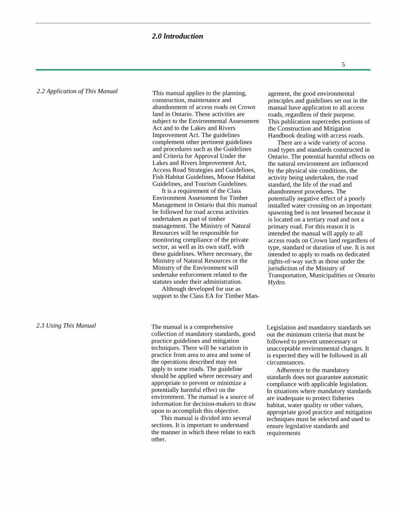
Preservation and restoration of vegetationis necessary to protect water quality.
• Water crossing proposals must bereviewed by the Ministry following theGuidelines and Procedures for ApprovalUnder the Lakes and RiversImprovement Act. This review may leadto a determination of: construction timerestrictions; a minimum waterwayopening size; special mitigationrequirements for preventing floodingand/or minimizing detrimental impactson fish habitat and water quality. Toavoid delays, this review should occurwell ahead of the proposed roadconstruction.
• During the construction andmaintenance of access roads and watercrossings, appropriate measures must betaken to prevent contamination of waterbodies by foreign materials such aslumber, nails, logs, brush, fuel, oil, lime,cement, asphalt, calcium chloride,sodium chloride, oil base woodpreservatives and herbicides. Noherbicides are to be sprayed within 10metres of a water crossing.
• The use of heavy constructionmachinery on streambeds is not permittedduring spawning and incubation periodsand must be kept to an absolute minimumat other times.
• Waterways must not be blocked so asto impede the free movement of waterand fish.
• Clearing and grubbing of lowvegetative cover within 100 m (350feet) of a water crossing, or otherwater body identified as beingsensitive by the Ministry, must be keptto the absolute minimum necessary forconstructing the project.
• Exposed mineral soil within 100metres (350 feet) of a water body mustbe graded to a stable angle of repose toprevent erosion.
• Appropriate erosion control and/orsedimentation control measures are tobe undertaken to protect water quality.
• Clearing operations in rights-of-waymust conform with the requirements ofthe Crown Timber Act, including theharvesting and utilization of salvageablewood.
• Access routes to lakes and streamsoutside the road right-of-way limitsmust not be constructed without theapproval of the Ministry.
• Materials moved duringconstruction, such as grubbing, earthfills and earth cut materials must not bepiled where they block drainagecourses.
• Permanent diversion orchannelization of an existing watercourse is generally inadvisable and, ifundertaken, must not create any moredisturbance of the natural environmentthan absolutely necessary. Waterwaysize and erosion resistance of the newchannel
4.0 Mandatory Standards
11
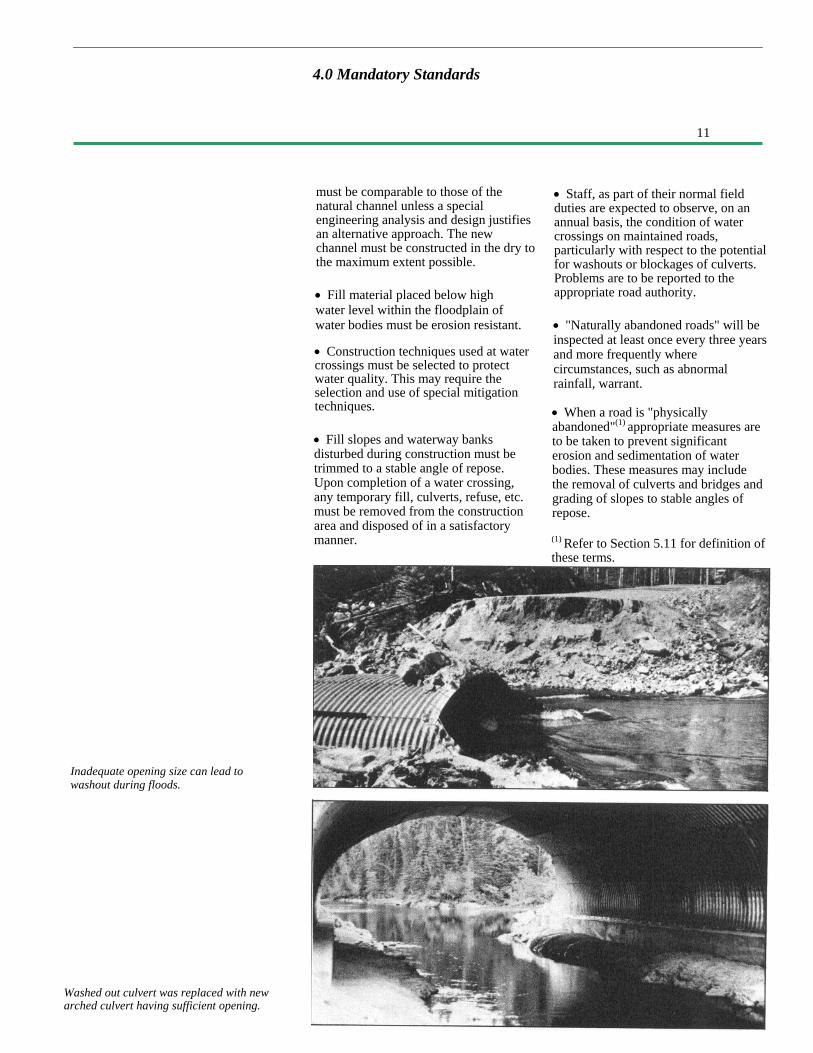
Washed out culvert was replaced with newarched culvert having sufficient opening.
4.0 Mandatory Standards
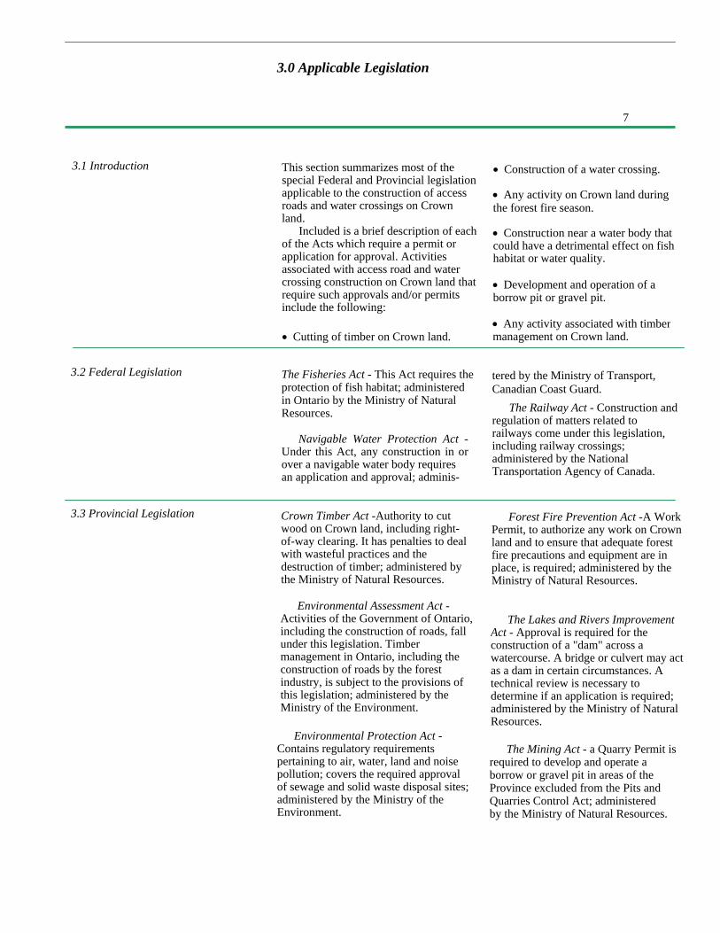
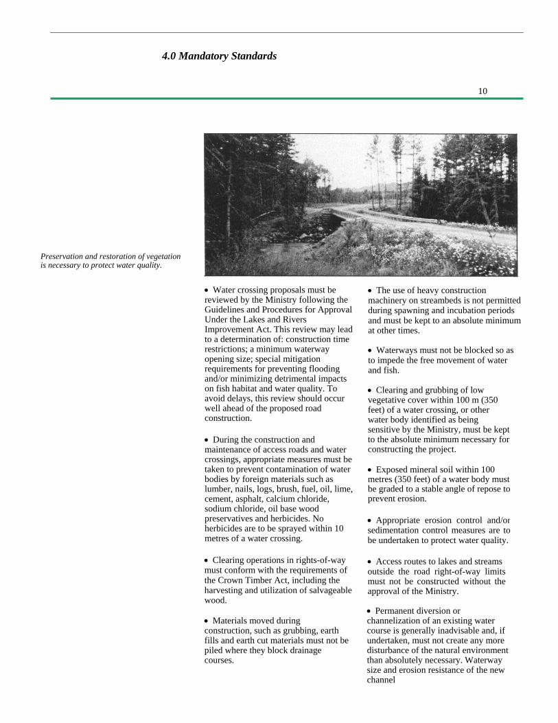
Inadequate opening size can lead towashout during floods.
must be comparable to those of thenatural channel unless a specialengineering analysis and design justifiesan alternative approach. The newchannel must be constructed in the dry tothe maximum extent possible.
• Fill material placed below highwater level within the floodplain ofwater bodies must be erosion resistant.
• Construction techniques used at watercrossings must be selected to protectwater quality. This may require theselection and use of special mitigationtechniques.
• Fill slopes and waterway banksdisturbed during construction must betrimmed to a stable angle of repose.Upon completion of a water crossing,any temporary fill, culverts, refuse, etc.must be removed from the constructionarea and disposed of in a satisfactorymanner.
• Staff, as part of their normal fieldduties are expected to observe, on anannual basis, the condition of watercrossings on maintained roads,particularly with respect to the potentialfor washouts or blockages of culverts.Problems are to be reported to theappropriate road authority.
• "Naturally abandoned roads" will beinspected at least once every three yearsand more frequently wherecircumstances, such as abnormalrainfall, warrant.
• When a road is "physicallyabandoned"(1) appropriate measures areto be taken to prevent significanterosion and sedimentation of waterbodies. These measures may includethe removal of culverts and bridges andgrading of slopes to stable angles ofrepose.
(1) Refer to Section 5.11 for definition ofthese terms.
12
5.1 IntroductionThe construction of access roads can
cause significant disturbance to thenatural environment. The seriousness ofthe impact depends on many factors,including:
• type of natural environment• terrain difficulty• soil types along the route• construction materials used• geometric road standard• construction and maintenancepractices• a mitigation techniques implemented• road abandonment practices
The good practices described in thissection apply to all types of roads. It isrecognized that not all guidelines may berelevant to all roads, however even lowstandard tertiary roads have the potentialfor causing significant harmful effects.The practices described should beconsulted as a matter of
course prior to and during themanagement of access road projects.
Access road activities can besubdivided into a series of operationsthat take place in a chronologicalsequence. Using this sequence, the goodpractices have been grouped into thefollowing components:
• road planning and location• a clearing• grubbing• earth grading• a rock grading• drainage ditches and culverts• swamp treatments• graveling• road maintenance• road abandonment
5.0 Access Roads – Good Practices

13
5.2 Road Planning and Location
Higher standard roads cost more moneyand result in greater environmentalchange.
This phase comprises the preconstructioncomponents of the corridor study, roadlocation and road design.
The level of technical evaluation,layout and design required on aparticular road depends on the geometricstandard, the terrain through whichthe road will be built and the methodof construction. At this stage, the finalalignment of the road is selected.Decisions about the location of aparticular road have an importantinfluence on the impact the road willhave on the natural environment.
Good Practices - Location:• Ensure areas of concern in theplanning stage have been identified anddealt with. This may require specialmitigation techniques such as protectionof canoe routes, erosion control at watercrossings, building neat push-outs foraesthetics, avoidance of osprey nests.• Select the location of water crossingswell in advance of construction,particularly those identified in TimberManagement Plans.
• Avoid unfavourable construction areasas much as possible. These include hillyterrain with steep grades (10% or more);areas with insufficient gravel; deepswamps; bedrock; erodible soils; andshallow soils areas.• For environmental as well aspractical considerations, roadalignments should follow the contoursof the land.
• Gentle grades (1-4%) are desirablefor proper drainage and economicalconstruction.• Long, sustained grades should beavoided since they allow excessiverunoff buildup in ditches and can lead toerosion.
• Keep roads away from recreationalareas, water bodies and wetlands, exceptwhere water access or aesthetic viewingis an objective of the road.• Buffer zones of undisturbedvegetation between access roads andwater bodies should be maintained andshould increase in width proportionallyto the increase in slope of land enteringthe waterway.
• Minimize the number of watercrossings.
• Geometric road standard should beappropriate for the intended use and forthe duration of use of the road.Construction to a higher standard thannecessary increases costs and has thepotential for more environmentaldamage.• Identify sources of material for roadconstruction, and consider locating theroad near these sources, in order tominimize haul distances and providebetter materials to work with.• Landings, loading areas andturnarounds should be located when theroad is being laid out. Landings shouldbe on high ground to avoid rutting andblocking of drainage paths.
5.0 Access Roads – Good Practices

14
5. 0 Access Roads - Good Practices
5.3 Clearing
Timber cut from the right-of-way clearingshould be utilized.
5.4 Grubbing
Clearing consists of cutting andremoving standing trees to make roomfor construction of the road. It is normalpractice to specify a minimum width ofclearing. This is done for severalreasons: to allow space for constructionequipment to operate without knockingdown standing trees; to provide safesight lines around curves; and, to allowdrying of the roadway in wet weatherand spring break-up. Maximum widthsshould also be specified to minimize theareal extent of disturbance caused byroad construction.
The equipment normally used forclearing includes chainsaws, bulldozers,wheeled skidders and other loading,slashing and haulage equipment forwood handling.Good Practices - Clearing
• Do not clear an area larger thannecessary to meet the geometric standardfor the road; control clearing width usingmarked sidelines.
• Reduce clearing width to theminimum needed for constructionwithin
Grubbing, or stripping, consists of theremoval and disposal of stumps,roots, brush, small trees, embedded logsand organic material overlying themineral soil.
Grubbing is done to expose themineral soil for three reasons:
• To prepare for earth gradingoperations.
• To improve roadway performance byeliminating weak organic material in thezone carrying wheel loads; and
• To minimize future sight distanceproblems that roadside vegetationcould cause.
100 metres (350 feet) of a watercrossing, or a water body identified bythe Ministry as being sensitive.
• Away from water crossings, aminimum width of 20 metres (66 feet)should be cleared to ensure the roadwill dry out, and to provide sight linesfor safety.
• Trees should be felled away fromstanding bush and water bodies.
• Push-outs should be pre-cut. Locatethem on the low side of the road, butwithout blocking drainage.
• Landings should be pre-cut, on highground, off the right-of-way, and inscrub brush areas if possible.
• Salvage merchantable timber fromright-of-way clearing.
• Clear in winter months to reducerutting.
• Slash debris should be disposed ofas part of the grubbing operation.
Full width grubbing is done where road-building materials are expected to comefrom the right-of-way area.Occasionally, in certain soil conditionsand on low standard roads, the grubbingmaterial is pulled to the centre andtrampled down to form part of theroadbed. On some roads, especially indeep fill areas, it is acceptable to notgrub; this will minimize impact onnatural environment. It should be kept inmind that it is the grubbing operationwhich exposes mineral soil to erosionand compaction.
The equipment usually used in thegrubbing operation are bulldozers andbackhoes. Special blades have been
15
• The stumps in swamp areas shouldbe shear bladed in winter if possible.
5.O Access Roads – Good Practices
5.5 Earth Grading
developed for bulldozers, featuring rake-like teeth or small shoes that elevate theblade to allow collection of the brushand stumps while leaving the organictopsoil on the right-of-way. It is usefulto use this equipment to retain lowvegetation and to minimize erosionproblems.
Good Practices - Grubbing:
• To ensure that trees on the bush lineare not under-cut, a cleared but notgrubbed buffer should be left along theedge of the right-of-way.
• Grubbing should not proceed too farahead of construction. This will limit thetime that the mineral soil is exposed toerosion.
• Grubbing material should not bepiled where it will block drainagecourses.
• If windrows are used, they should bekept behind roadside ditches and breaksshould be provided so animals can moveacross the right-of-way, say 5 metresevery 65 metres (16 feet every 200 feet).
• If push-outs are used, they should bepre-cut to a large enough size to avoidknockdown of standing trees.
Earth grading reshapes the originalground contours to the shape of the road,in profile and cross-section.
The operation includes theexcavation of earth cuts and theconstruction of earth fills. Lowerstandard roads tend to follow theoriginal ground contours more closely,because their geometric requirementsare less critical; this means that cut andfill depths will be less than those for ahigher- standard road constructed alongthe same route.
The equipment normally usedincludes bulldozers, front-end loaders,backhoes, dump trucks and scrapers. Inpoor soil areas, the use of backhoes forbuilding fills - by pulling in materialfrom within the right-of-way - is apreferred method. It allows for better
• Swamps should not be grubbed.
• If some organic material is left inplace, it will make nutrients available toensure rapid re-vegetation of the right-of-way. This can be done by usingspecial blades or attachments on abulldozer and by grubbing in winterwhen the blade can ride on the frost.
• In areas of fine grained soils (clays,silts and fine sands) which are subjectto erosion, the area to be grubbedshould be minimized.
• Grubbing in fine grained soil shouldbe avoided during wet weather. Thiswill prevent severe rutting andunnecessary disturbance of the clay orsilt soil. Postpone the grubbingoperation until drier conditions prevail,or close-cut the trees and do not grub.
material selection and creates lessdisturbance. Rather than having thematerial pushed into position, a backhoepicks the material up, moves it, thenplaces it where needed; this gives the filla chance to dry out and consolidatebefore it has to carry heavy traffic.
The use of well-drained, granularsoils produces strong roadbeds that areeasier to construct, and that will beerosion resistant. By paying closeattention to the shaping of the earthcross-section and the selection ofmaterials, and by providing for gooddrainage, initial costs will be minimized,maintenance costs will be reduced andpotential detrimental impacts on theenvironment will be prevented.

16
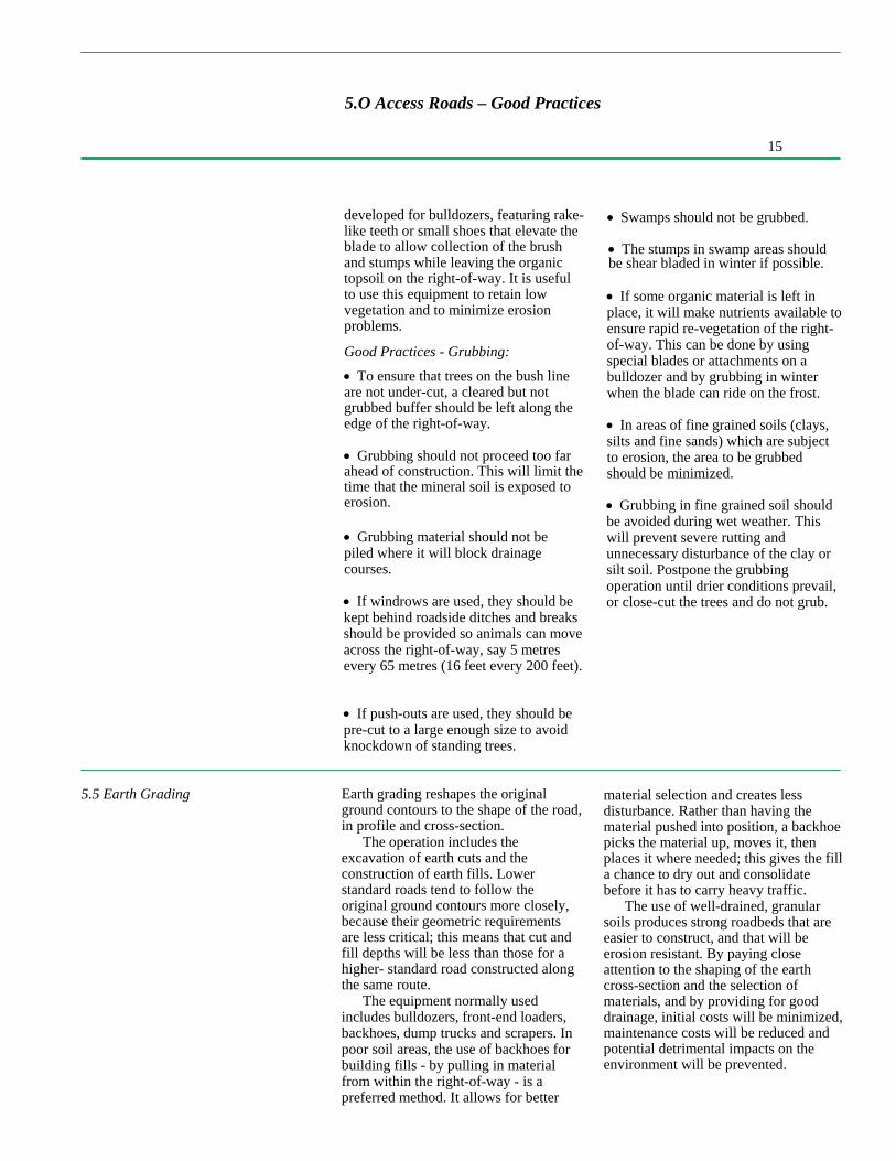
• When building fills on side slopes,benching into the original ground willprevent slippage along the interface.
5.0 Access Roads – Good Practices
Good Practices -Earth Grading:
• Soil instability due to soft clay,springs or erosion can result in roadfailure. Treat soil instability byreducing the loading (fill height) orwith counterbalancing side berms.Treat persistent springs with sub-surface drainage.
• Where there are potential seriousconsequences of soil instability orerosion, erosion control techniquesshould be used promptly.
• Retain natural vegetation near watercrossings as long as possible, to reducethe time that the soil is exposed; i.e.,delay cut excavations under the road-bed until the last moment.
• Do not dump waste material in areasthat may block the flow of water.
• Fill in or around water bodies shouldbe constructed with earth-free rock orclean, well-graded, granular material;this will help reduce the impact on fishhabitat and water quality.
• Install drainage culverts as part ofthe earth grading operation.
• Excavate cuts uphill to improvedrainage and make material moreworkable. Complete ditches as cuts arebeing excavated.
• Keep earth fills and earth cuts asshallow as possible, consistent with thegeometric standard being constructed. Aroad surface about one metre
(three feet) above the original groundshould be satisfactory for most roads,if the terrain is favourable.
• Grade and crown the earth grade asit is being constructed, to shed waterand minimize ponding in ruts.
• Fills should be constructed in shallow,full width layers with stable side slopes(1-5 to 2.0:1). Equipment should bemade to travel the full width of eachlayer to compact it and make the fillmore dense. This will minimize slopeerosion and soft shoulders.
• When borrow from outside the right-of-way must be trucked in, try to obtaingranular material. It makes a strongroadbed, drains well, is easy to compact,and is erosion-resistant.
• Limit the number of pits to minimizethe area of disturbance.
• When obtaining material byexcavation within or adjacent to theright-of-way, try to drain low pockets.This may not be necessary whenstanding water does not create anyproblems, e.g., in deep fill areas.
• Maintain adequate control overgrading operations to ensure the road isnot over-built or under-built. Thisusually requires some survey layout,staking limits of cuts and fills, andsupervision by a grading foreman.

17
• Where bedrock projects into theditch line of a roadside ditch,construct an off take ditch into thebush, install a cross culvert, orexcavate through the rock knob.
5.0 Access Roads - Good Practices
Fill construction in shallow, full-widthlayers ensures a stable road bed.
5.6 Rock Grading
• When working with wet, fine-grained soils (clays, silts), it may benecessary to push the material up andleave it to dry for some time. When dry,such otherwise unsuitable materials canmake an acceptable roadbed.
Benching will help stabilize slopes whenconstructing fills on steep side hills.
Use of the backhoe for this operationmay speed the drying time and reducedamage to the original ground.
Rock grading is the removal andmovement of solid rock or largeboulders to the desired gradeline. Theoperation involves stripping theoverburden, drilling, blasting,excavating, transporting and placing ofthe material into rock fills.
As with earth grading, the desiredroad profile determines cut and fillrequirements. For economic reasons,rock cut areas are avoided if at allpossible during location of the road. Inthe construction of access roads, it isaccepted practice to make a road morewinding, or to steepen road grades toavoid rock excavation.
Rock grading equipment normallyincludes compressors, air track rockdrills, backhoes, front-end loaders,bulldozers with ripper attachments, rocktrucks and dump trucks.
Good Practices - Rock Grading:
• Plan rock fracture to produce usablesize particles for rip rap and otherneeds on the construction project.
• Plan drilling patterns and limitexplosive loadings to an appropriatelevel that will shatter the rock and heap itup vertically, but will not throw thematerial into the bush. This will limitdamage outside the right-of-way andmake the material available for fill orother uses.
• Where ditches leading downhillfrom rock cuts pass over earth material,rip rap should be provided to protect theearth/rock interface from erosion.

18
5.0 Access Roads - Good Practices
5.7 Drainage Ditches and Culverts
A well drained roadbed can support heavierloads than an improperly drained road, andcan be used for more of the year.
Drainage consists of the excavation ofroadside ditches, the installation of crossculverts and the provision of off-takeditches. It is important to differentiatebetween drainage culverts and watercrossings. The drainage culvertsdiscussed in this section are thoserequired to pass local surface flowschannelized by the road construction.There is no defined channel prior toconstruction and there are no fish in thesechannels. Water crossings occur wherethe road crosses a natural water coursethat has a defined channel, they are dealtwith in Section 6. All culverts should beinstalled in a manner which minimizessedimentation as the downstreamreceiving water will eventually be fishbearing.
With proper drainage and protectionfrom standing water, most soil types canbe used to make economical accessroads. A well-drained roadbed cansupport heavier loads, and will be usablefor more of the year, than an improperlydrained road. Furthermore, it can usuallybe constructed with less material thanwould be needed if good drainage wasnot provided. Proper roadside drainagereduces erosion and damage to inundatedtrees and vegetation.
The usual equipment for thisoperation includes bulldozers, backhoes,front-end loaders, graders and dumptrucks.
Good engineering practice is usuallygood environmental practice. Softroadbeds, washouts and sedimentationare generally the consequences ofimproper culvert installations or lack ofditching.
Good Practices - Culverts:• Use permanent materials onpermanent roads (e.g., csp culvert). Ifthe road is temporary, culverts and filldeposited in the floodplain should beremoved when no longer required.
• Installation should be done in driestpossible time of the year.
• Installation should be carried outahead of fill construction or as part of it.
• Culverts should be placed so that tenpercent of their diameter is below theoriginal ground elevation. A high culvertwill cause ponding upstream and outleterosion downstream. Too low a culvertwill fill with sediment and may freezeover in the winter. A single larger pipemay be preferable to several smallerones, because it should be lesssusceptible to blockage or icing.
• In swamps, culverts should be placedwhere the organic depth is least tominimize settlement.
19
5.0 Access Roads -Good Practices
• Where cross-culverts are used ondown grades to divert flow andminimize ditch erosion, they should beangled across the road so water willflow easily.
• When foundation conditions are suchthat a sagging of the central portion ofthe culvert is anticipated, the centralportion should be installed with anupward camber. Anticipated sag willthen tend to restore the culvert to aconstant gradient.
• Culvert length should be selected toensure ends will not be blocked by fillslopes.
• The minimum culvert size used onroads needed for more than ten yearsshould be 500 millimetres (18 inches)in diameter.• Rip rap should be placed on theupstream fill slope around the culvertinlet, to the top of the pipe, to preventfill washout during high flow periods.
• If scour of the streambed down-stream of the culvert is expected due tothe high flow velocities, an erosionresistant apron or energy dissipatershould be provided.
Good Practices - Ditches:
• Ditching should be carried out aspart of earth grading, to encouragegood drainage early and to minimizesoil disturbance.
• Ditches should be constructeduphill, to avoid trapping rainwater.
• All roadside ditches should flow toan outlet downstream of the roadright-of-way.
• Ditches should be sized to handle theexpected runoff from the area drainingonto them. Large drainage areas mayrequire deeper or wider ditches thanare normally provided.
• On all-weather roads, ditches shouldensure that the water level is maintainedat least one metre (three feet) below theroad surface.
• Cross culverts and off take ditchesare required to ensure adequate road-side drainage. The recommendedspacing of these depends on groundslope and soil type, as indicated inTable 1.
20
5.0 Roads - Good Practices
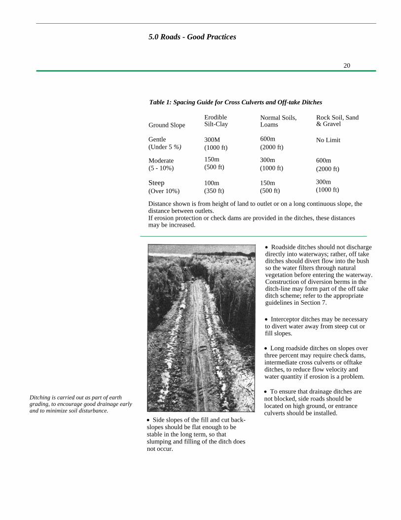
Table 1: Spacing Guide for Cross Culverts and Off-take Ditches
Ground Slope
Gentle(Under 5 %)
ErodibleSilt-Clay
300M(1000 ft)
Normal Soils,Loams
600m(2000 ft)
Rock Soil, Sand& Gravel
No Limit
Moderate(5 - 10%)
Steep(Over 10%)
150m(500 ft)
100m(350 ft)
300m(1000 ft)
150m(500 ft)
600m(2000 ft)
300m(1000 ft)
Distance shown is from height of land to outlet or on a long continuous slope, thedistance between outlets.If erosion protection or check dams are provided in the ditches, these distancesmay be increased.
Ditching is carried out as part of earthgrading, to encourage good drainage earlyand to minimize soil disturbance.
• Roadside ditches should not dischargedirectly into waterways; rather, off takeditches should divert flow into the bushso the water filters through naturalvegetation before entering the waterway.Construction of diversion berms in theditch-line may form part of the off takeditch scheme; refer to the appropriateguidelines in Section 7.
• Interceptor ditches may be necessaryto divert water away from steep cut orfill slopes.
• Long roadside ditches on slopes overthree percent may require check dams,intermediate cross culverts or offtakeditches, to reduce flow velocity andwater quantity if erosion is a problem.
• To ensure that drainage ditches arenot blocked, side roads should belocated on high ground, or entranceculverts should be installed.
• Side slopes of the fill and cut back-slopes should be flat enough to bestable in the long term, so thatslumping and filling of the ditch doesnot occur.
21
• The most common swamp treatmentmethod on access roads is to float theroad fill on the natural root mat andminimize disturbance of the organicdeposit. This is economical and, of themethods available, causes the leastdisturbance to the natural environment.
• Construction of swamp treatments inthe winter has several advantages: itpermits shear balding of stumps;heavier construction equipment cancross without getting bogged down ordisturbing the root mat; and,construction can also proceed beyondthe swamp without having to wait forthe treatment to be completed.
• Select a crossing location where thereis a well-developed root mat supportingtree growth.
5.0 Access Roads - Good Practices
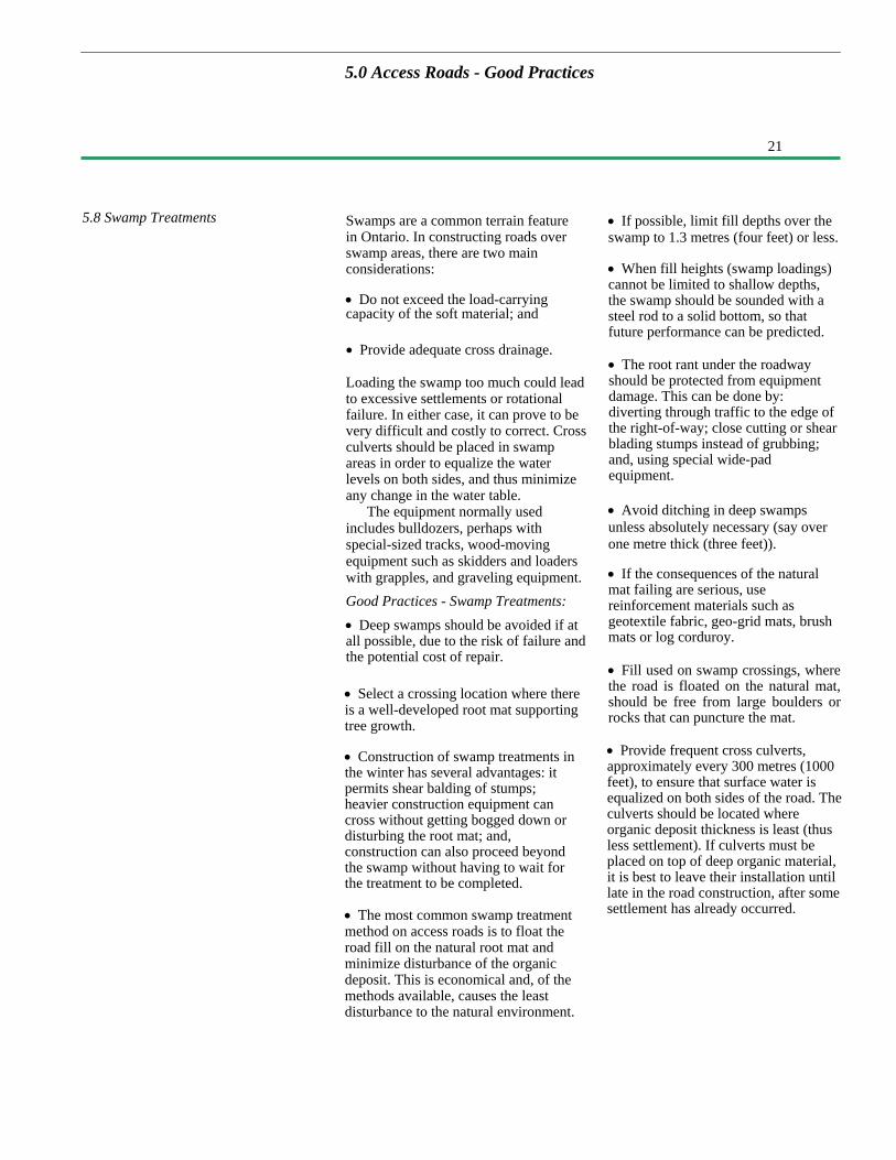
5.8 Swamp Treatments Swamps are a common terrain featurein Ontario. In constructing roads overswamp areas, there are two mainconsiderations:
• Do not exceed the load-carryingcapacity of the soft material; and
• Provide adequate cross drainage.
Loading the swamp too much could leadto excessive settlements or rotationalfailure. In either case, it can prove to bevery difficult and costly to correct. Crossculverts should be placed in swampareas in order to equalize the waterlevels on both sides, and thus minimizeany change in the water table.
The equipment normally usedincludes bulldozers, perhaps withspecial-sized tracks, wood-movingequipment such as skidders and loaderswith grapples, and graveling equipment.Good Practices - Swamp Treatments:• Deep swamps should be avoided if atall possible, due to the risk of failure andthe potential cost of repair.
• If possible, limit fill depths over theswamp to 1.3 metres (four feet) or less.
• When fill heights (swamp loadings)cannot be limited to shallow depths,the swamp should be sounded with asteel rod to a solid bottom, so thatfuture performance can be predicted.
• The root rant under the roadwayshould be protected from equipmentdamage. This can be done by:diverting through traffic to the edge ofthe right-of-way; close cutting or shearblading stumps instead of grubbing;and, using special wide-padequipment.
• Avoid ditching in deep swampsunless absolutely necessary (say overone metre thick (three feet)).
• If the consequences of the naturalmat failing are serious, usereinforcement materials such asgeotextile fabric, geo-grid mats, brushmats or log corduroy.
• Fill used on swamp crossings, wherethe road is floated on the natural mat,should be free from large boulders orrocks that can puncture the mat.
• Provide frequent cross culverts,approximately every 300 metres (1000feet), to ensure that surface water isequalized on both sides of the road. Theculverts should be located whereorganic deposit thickness is least (thusless settlement). If culverts must beplaced on top of deep organic material,it is best to leave their installation untillate in the road construction, after somesettlement has already occurred.

22
5.10 Road Maintenance either be maintained at minimal levels forlight recreational and other traffic uses orabandoned in an environmentally soundmanner as described in Section 5.11.
The operations carried out for roadmaintenance can be broken into two maingroups: routine and non-routine.
Routine operations include those day-to-day activities necessary to
Access roads are maintained during theperiod of time they are required.The level of maintenance on an accessroad varies depending on its use at anygiven time. For example, during woodextraction operations, when numerousheavily loaded trucks are using a road, itis maintained to keep the riding surfacevery smooth. Later, if the road is nolonger used for timber management, theroad use may change. It can
Elements of a Swamp Treatment, cross-section showing ”floating the road"
5.9 Graveling
5.0 Access Roads - Good Practices
This operation refers to the placing ofsand and gravel materials to form thestructural road sub-base and surface thatsupports the wheel loads.
A sand cushion may be used as asub-base under the gravel surface if theunderlying earth cut or fill materials arepoor and of low strength.
The operation generally involvesimporting select material from a gravelpit nearby.
The equipment normally usedincludes front-end loaders, dump trucks,bulldozers, graders and back- hoes.Occasionally, crushing units,compaction equipment and water trucksare also used.Good Practices - Graveling• For the top 150 millimetres (sixinches), a well-graded gravel withparticle sizes evenly distributed betweenclay size and 25 millimetre (one inch)
stones is preferred. It can be easilyplaced and compacted to the desiredshape and will be more stable under loadthan a poorer quality material. Well-graded gravel tends to be erosionresistant, and its use will reduce theamount of road maintenance required.
• Shape, compact and crown the earthgrade before placement of the gravellayer. This will minimize the amount ofgravel needed and it will shed waterseeping through porous gravel duringwet periods.
• Avoid rutting by providing anadequate depth of gravel so the roadwill be able to carry the types ofvehicles expected to be travelling over itduring the times it will be needed.

23
• During snow clearing operations,snow banks should be winged back. Thiswill decrease the time to melt the snow,and minimize spring saturation anderosion of the roadbed. It will also avoidcreating an obstruction to wildlifemovements.
• Salt should be stored in dry sheds, toprevent infiltration into the watertable.
Proper grading techniques will minimizeerosion of the roadfill material.
maintain the road for the traffic using it.These may include grading, snowplowing, and the maintenance ofdrainage by cleaning out blocked ditchesand culverts.
Non-routine maintenance includesmajor repairs and restoration. Sinceroads gradually deteriorate with time,there is a periodic need to restore thecondition of roads serving a long-termneed. These roads may require majormaintenance or re-construction torestore their original condition every tento twenty years. Example operationsfalling into this category include: brushcontrol with mechanical and chemicalmethods; replacement of gravelsurfacing material; repair of major flooddamage, and, replacement of sub-standard bridges.
If a road is not maintained, it shouldbe abandoned in accordance with theuse-management strategy for the road.Refer to Section 5.11, dealing with roadabandonment.
Good Practices - Maintenance:
• The usefulness and permanence of anaccess road depends on a good drainagesystem. Maintenance of drainageincludes: regular inspection, clean-out ofblocked ditches and culverts, grading toremove ruts and crowning of the road toshed water.
• During grading operations, loosematerials should be brought backtowards the center of the roadway toprevent the creation of berms thatcould channelize run-off down theroad and erode the fill slopes.
• Nuisance beaver activity aroundculverts should be dealt with (refer tomitigation techniques in Section 7).
• Heavy equipment should not be usedon roads during spring breakup, as thiswill lead to rutting, gravelcontamination and possible erosion.The spring breakup usuallycorresponds with the period of half-load restrictions on secondaryhighways.
• In winter, sand is preferred overchemical de-icing salts. Where used,alts should be applied sparingly.
5.0 Access Roads – Good Practices

24
5.11 Road Abandonment
5.0 Access Roads - Good Practices
• Remove roadside vegetation thatshades the road, for safety (visibility)and for drying of the road. In erodiblesoils, do not expose the mineral soilduring the brushing operation.
• Special mitigative techniques such assediment traps and check dams shouldreceive regular maintenance as long asthey are needed.
• Calcium chloride may be used tostabilize the road surface and controldust problems. It should always beapplied in accordance with themanufacturer's recommendations.
A Use Management Strategy isdeveloped for primary and secondaryroads as part of the Timber ManagementPlan or other planning process. The UseManagement Strategy addresses theduration of use for the road and whatactions are proposed when that use ends.The strategy may call for abandonmentof the road when its original purposeends. There are two forms ofabandonment:
Physical Abandonment occurs whenthere is a deliberate act to render a roadunusable by vehicular traffic. Physicalabandonment could include taking stepswhich will minimize the environmentalimpacts of non-maintenance.
Natural Abandonment occurs whenroad maintenance has ceased, yet stepsare not taken to prevent the use of theroad by vehicles. With naturalabandonment, no physical changes aremade to the road.
In either case, abandonment shouldbe carried out in an environmentallysound manner. Erosion and decayprocesses can lead to sedimentproblems in the area of watercrossings.
• If herbicides are used for vegetationcontrol, the person applying theherbicide should be licensed and a 10metre buffer zone must be maintainedadjacent to all water bodies. Mechanicalmeans of vegetation control are usuallypreferable environmentally and are ofteneconomically competitive.
• Following timber managementoperations along the roadside, theroadway cross section should be restoredby repairing damaged slopes, culvertsand ditches.
Consideration should be given toregeneration of the road right-of-wayto make the area productive forgrowing trees and to prevent erosion.This will lead to a more rapid re-establishment of natural conditions.
Erosion ControlPreventative measures can be taken to
minimize erosion of the road filland subsequent sedimentation in thewatercourse. When a road is notmaintained, frost and runoff will lead toloosening and erosion of fill and roadsurfaces. In the area of water crossings,the roadway slopes downhill, towards thestream. Water flowing down the road canerode the gravel surface and underlyingfill. Preventative measures can be takento minimize erosion of the road fill andsubsequent sedimentation in thewatercourse.
Water bars can be used to controlsurface water runoff and minimizeerosion of the road surface and fill. Waterbars are transverse ditches excavatedacross the road surface to intercept runoffand deflect it towards the ditches insteadof flowing down the road surface. Theoutlet of a water bar should be extendedinto an area that is erosion resistant andthat will filter out sediment. This controlof runoff will prevent surface erosion andlead to quicker re-establishment ofvegetation on the road.
25
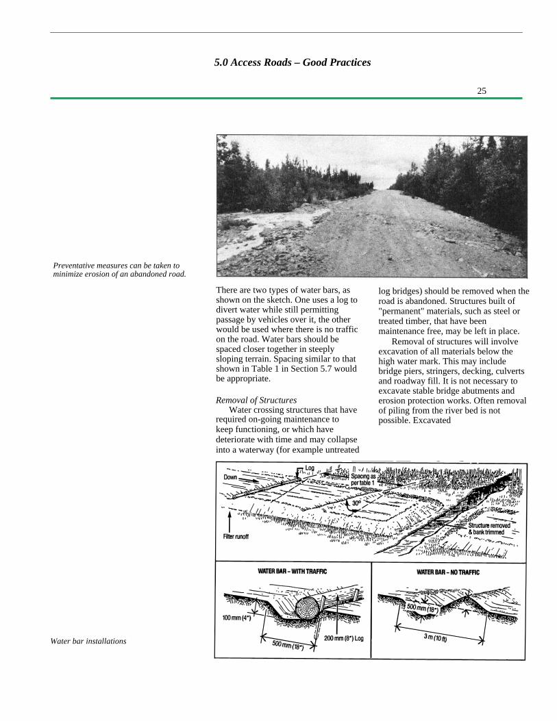
Water bar installations
Preventative measures can be taken tominimize erosion of an abandoned road.
There are two types of water bars, asshown on the sketch. One uses a log todivert water while still permittingpassage by vehicles over it, the otherwould be used where there is no trafficon the road. Water bars should bespaced closer together in steeplysloping terrain. Spacing similar to thatshown in Table 1 in Section 5.7 wouldbe appropriate.
Removal of StructuresWater crossing structures that have
required on-going maintenance tokeep functioning, or which havedeteriorate with time and may collapseinto a waterway (for example untreated
log bridges) should be removed when theroad is abandoned. Structures built of"permanent" materials, such as steel ortreated timber, that have beenmaintenance free, may be left in place.
Removal of structures will involveexcavation of all materials below thehigh water mark. This may includebridge piers, stringers, decking, culvertsand roadway fill. It is not necessary toexcavate stable bridge abutments anderosion protection works. Often removalof piling from the river bed is notpossible. Excavated
5.0 Access Roads – Good Practices

26
5.0 Access Roads - Good Practices
Failure to maintain culverts and ditchesmay lead to a road washout.
material should be trucked away to asuitable disposal site at least 100 metres(350 feet) away from the water course.The banks and approach fills should begraded and trimmed to a stable anglesimilar to the adjacent natural riverbanks. The banks should then beprovided with erosion control treatmentif necessary to prevent erosion. Exposedsoil on the river banks should have seedand fertilizer applied to speed re-vegetation.
27
6. 0 Water Crossings - Good Practices
6.l lntroduction
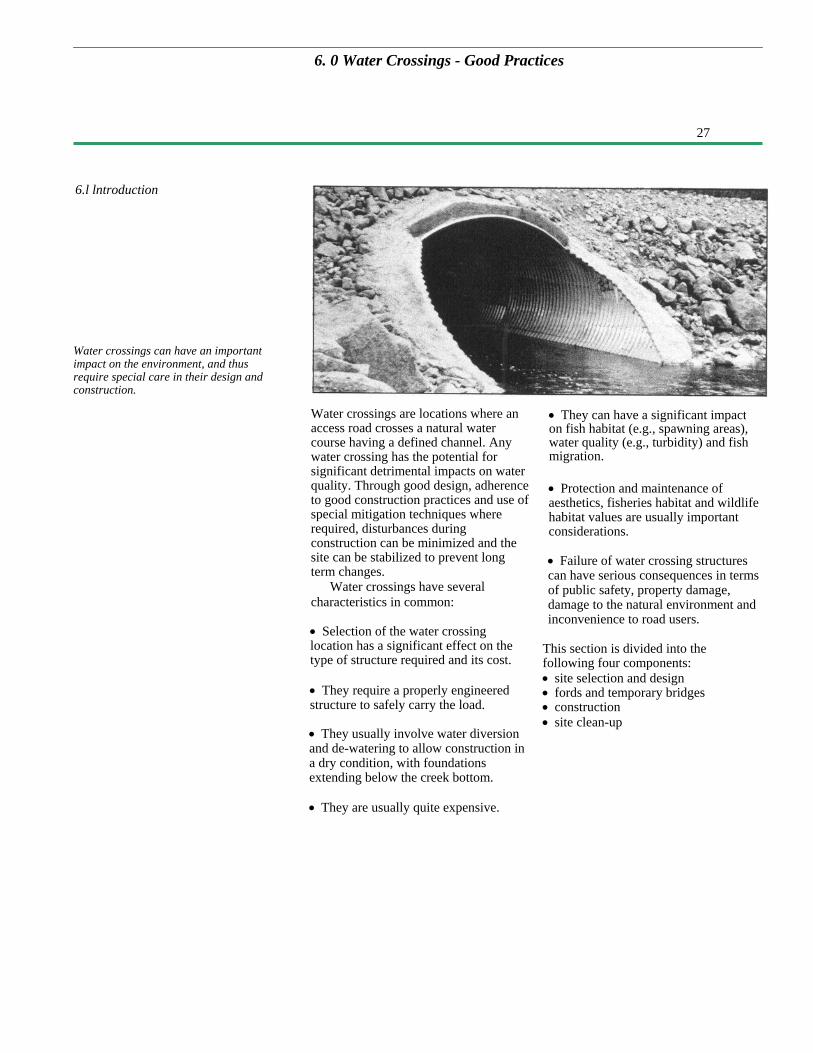
Water crossings can have an importantimpact on the environment, and thusrequire special care in their design andconstruction.
Water crossings are locations where anaccess road crosses a natural watercourse having a defined channel. Anywater crossing has the potential forsignificant detrimental impacts on waterquality. Through good design, adherenceto good construction practices and use ofspecial mitigation techniques whererequired, disturbances duringconstruction can be minimized and thesite can be stabilized to prevent longterm changes.
Water crossings have severalcharacteristics in common:
• They can have a significant impacton fish habitat (e.g., spawning areas),water quality (e.g., turbidity) and fishmigration.
• Protection and maintenance ofaesthetics, fisheries habitat and wildlifehabitat values are usually importantconsiderations.
• Failure of water crossing structurescan have serious consequences in termsof public safety, property damage,damage to the natural environment andinconvenience to road users.
• Selection of the water crossinglocation has a significant effect on thetype of structure required and its cost.
• They require a properly engineeredstructure to safely carry the load.
This section is divided into thefollowing four components:• site selection and design• fords and temporary bridges• construction• site clean-up
• They usually involve water diversionand de-watering to allow construction ina dry condition, with foundationsextending below the creek bottom.
• They are usually quite expensive.

28
6.2 Site Selection and Design
6. 0 Water Crossings - Good Practices
A preferred site for construction is in arapids section of a stream or river. Theseareas are often of high value forfisheries as spawning areas; as well,rapids are important for recreation. Thearea adjacent to a rapids may containhistorical or archaeological material.Although these other values must beconsidered and protected, from anengineering viewpoint a rapids siteoffers the following advantages:
• Soils are usually resistant to erosionat high flow velocity.
• Foundation conditions are usuallygood, requiring less river bottomdisturbance.
• The effects of upstream backwater,due to the constriction created by thecrossing, will be limited to a shortlength of river.
• Water depths are usually shallow, andthe encroachment for cofferdams toconstruct abutments or piers will beminimal.Good Practices - Site Selection anddesign
• Avoid poor crossing sites if at allpossible. A poor site would be onewhere:
- Water depths at abutments and piersare great, i.e., over two metres (sixfeet).
- Soils are erodible and/or requireexpensive foundations to distributethe load, i.e., clay, silt or fine sand.
- Water surface widths are quite wideand flow velocities are low.
- Steep high banks or hilly approachescould make satisfactory roadconstruction to the water crossingvery costly.
- There are areas of bank instability,erosion or bends in rivers.
• Occasionally, islands can be used in arapids or at waterfalls, to break a longspan into two or more shorter spans.This also makes de-watering muchsimpler, since one channel can becompletely closed at a time.
• If recreation or fisheries values arehigh in the area, the crossing locationmay have to be adjusted to a site thatminimizes the impact on these values.For this reason, alternatives to thepreferred site should be considered.
• Select a structure appropriate to thesite. Commonly used alternatives are:
- Bridges with crib abutments,single span or multiple spanscorporating piers in the river.
- Bridges with pile-supportedabutments of single span ormultiple spans.
- Single corrugated steel pipe culvertor multiple csp culverts; thesecould be either circular pipe withcouplers or field-assembledstructural plate.
- Arch-type culverts incorporatingtwo side footings and a corrugatedsteel arch to support the fill. Thistype of culvert leaves the naturalstreambed between the footingson either side.
- Box culverts with closed or openbottoms.
• For streams which are used for fishmigrating or spawning areas, bridges orarch culverts, which retain the naturalstream bottom and slope, are preferredover pipe culverts.
• The crossing should have structuralcapacity to carry the vehicle loadsexpected to cross it.
• The waterway opening size should beselected to minimize the risk of washoutduring the expected life of the structure.

29
Alternative water crossing structures
• Hydrologic and hydraulic analysesshould be in accordance with designprocedures developed for Ontario use;refer to the Ministry of TransportationDrainage Manual. This conforms withreview criteria under the Lakes andRivers Improvement Act.
• The waterway opening size should beselected to ensure that upstream waterlevels will be acceptable, and that flowvelocities will not be too high to preventfish migration. Multiple smaller pipeswill have lower flow velocity and maybe preferred for fish migration purposesbut may be more susceptible to blockageby ice or debris. The maximum numberof culverts at a water crossing should beno more than three.
• Culvert size should be selected sonormal water levels rise no higher thanhalf the diameter of the pipe.
• If possible, align the road so itcrosses the waterway at right angles.Bridge abutments and piers should bealigned parallel to the direction offlow.
• It may be appropriate to place a dip inthe approach grade to allow waterspillage over the road if the pipecapacity is exceeded. This would alsolower repair costs if a washout occurred.
• Select adequate lengths of culvertsand use wing walls on bridges, to keepfill from spilling into flowing water, andto reduce maintenance costs.
• Design mitigative techniques toaccommodate any special requirementsidentified through the planning phase, orby Ministry staff during their review ofthe proposed construction.
6.0 Water Crossings – Good Practices
30
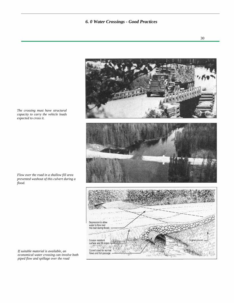
The crossing must have structuralcapacity to carry the vehicle loadsexpected to cross it.
Flow over the road in a shallow fill areaprevented washout of this culvert during aflood.
If suitable material is available, aneconomical water crossing can involve bothpiped flow and spillage over the road
6. 0 Water Crossings - Good Practices

31
6. 0 Water Crossings - Good Practices
6.3 Fords and Temporary Bridges
Ice bridge - temporary water crossing forwinter access
(a) FordsFording, or driving through a watercourse, may be an alternative used foraccess in limited specificcircumstances. Sites favourable for useas a ford are those where:
• The streambed has a firm rock orcoarse gravel bottom and where theapproaches are both low and stableenough to support traffic.
• Use of the ford will be temporaryand limited to low volumes of lightvehicles such as initial access duringclearing operations, or for miningexploration equipment.
• The water depth should be less thanone metre (three feet).
The natural carrying capacity of astream bottom can be improved byconstructing an underwater roadbedusing log corduroy, coarse gravel, rockfill or gabions. If used, these materialsshould be set into the bottom so thedriving surface will be flush with thestream bed to minimize erosion and toallow fish passage.
Good Practices - Fords• Crossings should be at right anglesto the stream.
• The road width should be not morethan 10 metres (32 feet) wide and itshould be well marked to be visible todrivers.• If necessary, stabilize the approachesby using non-erodible material to 15metres (50 feet) up the bank on bothsides of the ford.
• Fords should be constructed andused during the driest times of theyear.
• Minimize the amount of vegetationremoved adjacent to the water crossing.
• Fish passage should be accommodatedby maintaining a water depth of at least200 millimeters (eight inches) or thenatural stream depth at the location.
32
6. 0 Water Crossings - Good Practices
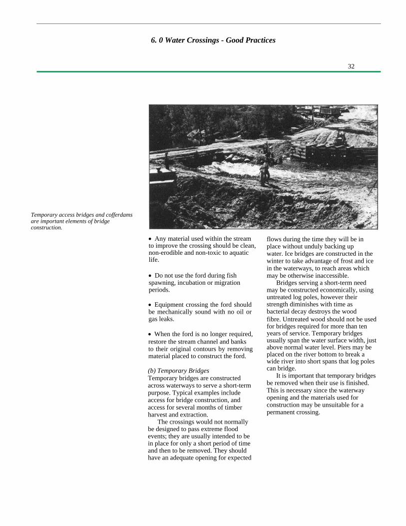
Temporary access bridges and cofferdamsare important elements of bridgeconstruction.
• Any material used within the streamto improve the crossing should be clean,non-erodible and non-toxic to aquaticlife.
• Do not use the ford during fishspawning, incubation or migrationperiods.
• Equipment crossing the ford shouldbe mechanically sound with no oil orgas leaks.
• When the ford is no longer required,restore the stream channel and banksto their original contours by removingmaterial placed to construct the ford.
(b) Temporary BridgesTemporary bridges are constructedacross waterways to serve a short-termpurpose. Typical examples includeaccess for bridge construction, andaccess for several months of timberharvest and extraction.
The crossings would not normallybe designed to pass extreme floodevents; they are usually intended to bein place for only a short period of timeand then to be removed. They shouldhave an adequate opening for expected
flows during the time they will be inplace without unduly backing upwater. Ice bridges are constructed in thewinter to take advantage of frost and icein the waterways, to reach areas whichmay be otherwise inaccessible.
Bridges serving a short-term needmay be constructed economically, usinguntreated log poles, however theirstrength diminishes with time asbacterial decay destroys the woodfibre. Untreated wood should not be usedfor bridges required for more than tenyears of service. Temporary bridgesusually span the water surface width, justabove normal water level. Piers may beplaced on the river bottom to break awide river into short spans that log polescan bridge.
It is important that temporary bridgesbe removed when their use is finished.This is necessary since the waterwayopening and the materials used forconstruction may be unsuitable for apermanent crossing.

33
6. 0 Water Crossings - Good Practices
6.4 Construction
Construction of large culverts "in thedry" is a key to proper installation.
A cofferdam allows abutmentconstruction in an area isolated fromflowing water.
Water diversion for construction of watercrossings
Considering the effort that is normallyinvested in site selection and designprior to construction of a major watercrossing, those responsible for on-sitework should be aware of potentialenvironmental impacts, and should takeappropriate precautions to ensure thoseimpacts under their control are kept to aminimum. Normally, this precautionadds little or no additional cost to theproject.
In most cases, the satisfactoryconstruction of a water crossing requiresthat flowing water be diverted awayfrom work areas so that the structure canbe constructed under dry conditions.Excavation for a bridge in the river bed,or placement of a large culvert, shouldnot be done in flowing water. Rather,the work area should be isolated with acofferdam or stream diversion.
Often there may be access to only oneside of a water crossing, and it will benecessary to construct a means oftemporary access to facilitateconstruction.
If a culvert is to be installed in aflowing stream channel, the water shouldbe diverted around the work site duringconstruction. Isolating the work site fromthe flow of water is necessary tominimize the release of soil into thewater course and to ensure a satisfactoryinstallation in a dry environment. Twomethods of water diversion arecommonly used for culvert installations:construction in the stream bed, orconstruction in a new channel, these aredetailed in the sketch.
If a bridge is to be installed it isusually not possible to divert all of the
34
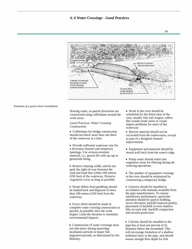
Elements of a good culvert installation
6. 0 Water Crossings - Good Practices
flowing water, so partial diversions areconstructed using cofferdams around thework areas.Good Practices- Water CrossingConstruction• Cofferdams for bridge constructionshould not block more than one thirdof the waterway at a time.
• Work in the river should bescheduled for the driest time of theyear, usually July and August, unlessthis would create noise or visualimpact problems for users of thewaterway.• Borrow material should not beexcavated from the watercourse, exceptas part of a designed channelimprovement.
• Provide sufficient waterway size fora diversion channel and temporaryopenings. Use erosion-resistantmaterial, i.e., gravel fill with rip rap orgeotextile lining.
• Restrict clearing width, and do notgrub the right-of-way between theroad and bush line within 100 metres(350 feet) of the waterway. Preservevegetative cover as long as possible.
• Equipment and materials should bestored well back from the water's edge.
• Pump water should outlet intovegetative areas for filtering during de-watering operations.
• The number of equipment crossingsin the river should be minimized byconstructing a temporary bridge.
• Waste debris from grubbing shouldbe hauled back and disposed of morethan 100 metres (350 feet) from thewaterway.
• Every effort should be made tocomplete water crossing construction asquickly as possible once the workbegins. Limit the duration to minimizeenvironmental impacts.
• Culverts should be installed inaccordance with manuals available fromthe pipe manufacturers. To ensuresatisfactory performance, particularattention should be paid to bedding,invert elevation, backfill material quality,placement of backfill in even shallowlifts on each side, backfill compactionand erosion protection.
• Construction of water crossings mustnot take place during spawning/incubation periods or major fishmigration periods, as determined by theMinistry.
• Culverts should be installed so thepipe has at least ten percent of itsdiameter below the streambed. Thiswill encourage formation of a shallowsediment layer in the pipe, and shouldensure enough flow depth for fish

35
6. 0 Water Crossings - Good Practices
6.5 Site Clean-up
If proper construction procedures arefollowed, the impact of bridgeconstruction is short term.
migration. During flood periods, thesediment will quickly erode. Thispractice will also minimize the chanceof undercutting at inlet or outlet.
• Control materials on the job so thatloose boards, nails and other debriswill not enter the waterway and flowdownstream. A log boom should beused downstream of the bridge site ifthere is a chance that debris (lumber)could fall into the water and becarried downstream.
• Do not clean concrete buckets,wheelbarrows, shovels in water bodies.Instead, wash them with hoses so thatrun-off is filtered through vegetation.Prevent the entry of lime, cement orfresh concrete into waterways.
• Oil-based treated timber (pentach-lorophenol, creosote) used below or nearwater level should be reasonably dry,without excessive surface oils. Timberswith oil base preservative treatmentsshould be ordered early to allow airdrying before use. Those with abundantsurface oils should be usedat the back of the cribs, against theapproach fill.
• Field cuts and drill holes should bepainted liberally with preservative toprevent decay; care should be taken toavoid contamination of the water byfield-applied preservatives.
• If the project is a bridge replacement,remove the old stringers and decking. Ifreasonably possible, also removefoundation piers and abutments unlessthese may be useful to break up ice orprotect against erosion.
• If culverts are founded on softmaterial, a granular bedding shapedwith a camber should be provided, sothat when settlement occurs, the pipewill function.
• For pier construction in open water, inwhich there are erodible river bottomsediments and where water quality mustbe protected, silt barrier curtains floatingon the surface and anchored to thebottom should be installed around thework area.
The final stage of construction is clean-up of the site. An extra effort on the partof construction staff can assist in therestoration of stable ground contoursand protective vegetative cover,
to prevent erosion and make thecrossing more attractive in appearanceto those who view it from the road orthe water.
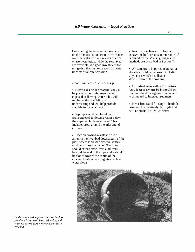
36
Considering the time and money spenton the physical structure to carry trafficover the waterway, a few days of efforton site restoration, while the resourcesare available, is a good investment formitigating the long term environmentalimpacts of a water crossing.
Good Practices - Site Clean- Up
• Heavy rock rip rap material shouldbe placed around abutment facesexposed to flowing water. This willminimize the possibility ofundercutting and will help providestability to the abutment.
• Rip rap should be placed on fillareas exposed to flowing water belowthe expected high water level. Thisincludes areas around the inlet end ofculverts.
• Place an erosion-resistant rip rapapron in the river bed downstream of thepipe, where increased flow velocitiescould cause serious scour. The apronshould extend six culvert diametersbeyond the end of the pipe and it shouldbe sloped toward the centre of thechannel to allow fish migration at lowwater flows.
• Restore or enhance fish habitat(spawning beds or aids to migration) ifrequired by the Ministry; suggestedmethods are described in Section 7.
• All temporary imported material onthe site should be removed, includingany debris which has floateddownstream of the crossing.
• Disturbed areas within 100 metres(350 feet) of a water body should bestabilized and re-vegetated to preventerosion and to intercept sediment.
• River banks and fill slopes should betrimmed to a relatively flat angle thatwill be stable, i.e., 2:1 or flatter.
Inadequate erosion protection can lead toproblems in maintaining road width, andwashout before capacity of this culvert isreached.
6.0 Water Crossings – Good Practices

37
• erosion and sediment control• control of beaver problems• fish habitat protection• aesthetic considerations
7.0 Mitigation Techniques
7.l lntroduction The environmental guidelines presentedin the previous sections arerecommended practice for all accessroad construction. In addition, there willbe occasions when special mitigationtechniques are needed to deal with apotentially serious problem, or to protectspecific values that have been identifiedas needing protection from the impactsof construction.
This section is intended as a sourceof information for those involved in roadconstruction who require technical detailconcerning such mitigation techniques.The need to implement a specialtechnique in order to prevent seriousproblems from developing could arise insituations such as the following:
• water crossings where there areimportant fish habitat, such as spawningbeds, that could be destroyed ifsediment levels are high.
• areas of concern identified duringthe planing phase.
• special values identified in advancethat are to be protected from potentialnegative impacts (e.g. tourism).
• unexpected conditions identifiedduring construction that requiretreatment or protection (e.g. erosion,archaeological material).
The subject is not treated here in anexhaustive manner; rather, commonlyoccurring treatments are described, andreferences are provided for those whorequire more information.
The techniques described arecurrently used in Ontario on accessroads and, if properly implemented, canmitigate the specific impact of roadconstruction being addressed. Thematerial covered in this section includes:
Even though special methods andmeasures exist for mitigating the impactof road construction, they may not beapplied unless a need for themis apparent and a rational decision ismade requiring their use.
Considerations for assessing thedegree and extent of mitigationtechniques required should include thefollowing:
• compliance with standards andapplicable legislation• the value of the tangible andintangible resources to be protected• the cost of supplying the protection• the pre-construction conditions in theenvironment, i.e., natural waterturbidity, natural erosion.
This document does not presume todetermine when, where and at whosecost, mitigation techniques should beused; these are the perogative of thoseinvolved in the decision-making processpreceding approval of road constructionon Crown land. Whenever such choicesmust be made by those directly andindirectly involved in a project, theirvalue systems, preferences, traditionsand customs all have an effect on theultimate decisions. Thus, one groupmight go to great lengths to protect andpreserve a resource that would get littleattention in another area. Theconsiderations and criteria for specialmitigation techniques should thereforebe viewed by those making the decisionsin light of their own perceptions of whatis valuable, what is right and what isacceptable in the public interest.
Through the use of writtendescription, illustrative sketches andphotography, the objective here is toprovide sufficient generic designinformation on the recommendedtechniques so as to minimize the needfor further reference to other documents.
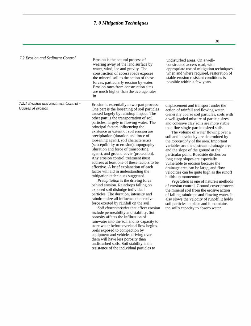
38
7. 0 Mitigation Techniques
7.2 Erosion and Sediment Control
7.2.1 Erosion and Sediment Control -Causes of erosion
Erosion is the natural process ofwearing away of the land surface bywater, wind, ice and gravity. Theconstruction of access roads exposesthe mineral soil to the action of theseforces, particularly erosion by water.Erosion rates from construction sitesare much higher than the average ratesin
Erosion is essentially a two-part process.One part is the loosening of soil particlescaused largely by raindrop impact. Theother part is the transportation of soilparticles, largely in flowing water. Theprincipal factors influencing theexistence or extent of soil erosion areprecipitation (duration and force ofloosening agent), soil characteristics(susceptibility to erosion), topography(duration and force of transportingagent), and ground cover (protection).Any erosion control treatment mustaddress at least one of these factors to beeffective. A brief explanation of eachfactor will aid in understanding themitigation techniques suggested.
Precipitation is the driving forcebehind erosion. Raindrops falling onexposed soil dislodge individualparticles. The duration, intensity andraindrop size all influence the erosiveforce exerted by rainfall on the soil.
Soil characteristics that affect erosioninclude permeability and stability. Soilporosity affects the infiltration ofrainwater into the soil and its capacity tostore water before overland flow begins.Soils exposed to compaction byequipment and vehicles driving overthem will have less porosity thanundisturbed soils. Soil stability is theresistance of the individual particles to
undisturbed areas. On a well-constructed access road, withappropriate use of mitigation techniqueswhen and where required, restoration ofstable erosion resistant conditions ispossible within a few years.
displacement and transport under theaction of rainfall and flowing water.Generally coarse soil particles, soils witha well-graded mixture of particle sizesand cohesive clay soils are more stablethan fine single-particle sized soils.
The volume of water flowing over asoil and its velocity are determined bythe topography of the area. Importantvariables are the upstream drainage areaand the slope of the ground at theparticular point. Roadside ditches onlong steep slopes are especiallyvulnerable to erosion because thedrainage area can be large, and flowvelocities can be quite high as the runoffbuilds up momentum.
Vegetation is one of nature's methodsof erosion control. Ground cover protectsthe mineral soil from the erosive actionof falling raindrops and flowing water. Italso slows the velocity of runoff, it holdssoil particles in place and it maintainsthe soil's capacity to absorb water.
39
7.0 Mitigation Techniques
7.2.2 Erosion and Sediment Control -Design Principles
The principles of erosion and sedimentcontrol design are based on simplecommon sense. Erosion control isdone to prevent or minimize the erosionof soil. Sediment control is the trappingof suspended soil particles beingtransported downstream in flowingwater to prevent their discharge into theaquatic environment of a stream.Erosion control is obviously the onlyeffective long-term solution, whereassediment control is a short-term remedyto minimize the impact of unavoidableerosion that does occur during theconstruction period.
The eight principles of erosion andsediment control are:
1. Fit the road to the terrainIn the planning, design and
construction of access roads thismeans: avoid erodible soil sites; followthe ground contours as much aspossible; and, do not construct deeperfills and cuts than the geometric roadstandard requires.
2. Minimize the duration of soilexposure
Limit the duration of exposure byscheduling the work so constructioncoincides with the dry season andcomplete grading operations soonafter the grubbing operation exposes thesoil.
3. Retain existing vegetation wherefeasible
Very little erosion occurs on soilcovered with undisturbed naturalvegetation. Re-establishment ofcomparable coverage after constructioncan take a long time. Limit the soilexposed by grubbing to the area whereconstruction will actually occur.
4. Grade disturbed soil to a stable slopeA slope which is inherently unstable
will be unable to develop a satisfactoryvegetative cover until it has eroded backto a stable angle of repose. For
most soils encountered in access roadconstruction in Ontario, this means cutand fill slopes should be shaped to aslope between 1.5 and 2.0 horizontal to1.0 vertical.
5. Encourage re-vegetationA properly re-vegetated soil will be
protected from erosion indefinitelywithout any need for human attention.Re-vegetation will occur naturally if theslope is stable. Re-vegetation can beencouraged by leaving some organicmaterial mixed in the uppermost soillayer and/or by seed and fertilizertreatments.
6. Divert runoff away from exposed soil
Surface water drainage that wouldnaturally flow over the exposed soilcan sometimes be diverted away fromthe area. Runoff collected in roadsideditches should be diverted to an outletoff the right-of-way. The frequency ofoutlets and cross-drains to carry waterfrom upstream to downstream side ofthe road should be designed to fit theground slope involved.
7. Keep runoff velocities lowThe energy of flowing water
increases with the square of the velocity.Thus, less erosion will occur if the wateris moving slowly. Flow velocities can bekept low by lining erodible soils withrough surfaces such as vegetation, rip rapand brush. The construction of checkdams in ditches will break the flowmomentum and reduce velocities.Flattening the steepness of a slope andcreating roughness in the flow path ofwater will reduce velocities. Ditch sizesshould be selected to handle the expectedrunoff from precipitation - this meansthat larger ditches are needed to handlerunoff from larger drainage areas.

40
7.0 Mitigation Techniques
7.2.3 Erosion and Sediment Control -Mitigation Techniques
8. Trap sediment before it can causedamage
Some erosion during construction isunavoidable. In order to preventsedimentation of streams it is desirableto trap sediment on land before itreaches the aquatic environment. Themost common method used on accessroads is the diversion of runoff into theadjacent forest floor where suspendedsoil particles are filtered out as runoffflows through the surface vegetation andlitter. The placement of a brush
The technology for erosion and sedimentcontrol is well developed. Accepted,proven techniques are described in detailin the Ministry of TransportationDrainage Manual and The Erosion andSediment Control Handbook (seereferences). In this section, techniqueswhich are particularly suitable for use onaccess roads in Ontario have beenselected for detailed presentation.
Flexibility in the construction ofaccess roads allows individuals theopportunity to exercise innovation inmitigating the effects of erosion andsediment in a variety of ways. Relativelysimple and inexpensive techniquesdeveloped in a local area can be just aseffective as more expensive methodsfound in a textbook.
barrier made with slash debris on thelower slope area can also create afilter. Sediment traps can be made byexcavating a depression downstream ofthe sediment source that will pond waterso suspended soil can settle out. Anothermethod of trapping sediment is to filterthe runoff from an area through a "siltfence" made of geotex- tile fabric orstraw bales. The water passes throughbut silt and sand is filtered out.
The techniques described below are:• rip rap• slope modification• re-vegetation• check dams• sediment traps• brush barriers• silt fences• a forest floor filter
Each of these techniques is based on oneor more of the principles describedpreviously. The implementation ofeconomical control measures, when andwhere required, will reduce theenvironmental damage caused byerosion and sedimentation. Theeffectiveness of the mitigationtechniques described may be increasedby combining more than one method.For example, the use of a brush barrier,together with seed and fertilizer, will bemore effective than either method on itsown.

41
Erosion Control Using Rip Rap Locations:Rip rap may be used on any exposed
mineral soil subjected to flowing waterwhere the velocity of water flow,seriousness of erosion, steepness ofslope, or material type, preventssatisfactory establishment of vegetativecover. Examples could include:
• Ditches in erodible soils on a slope ofmore than three percent could result inflow velocities that will erode andtransport ditch bottom material.
• A fill slope at the entrance to aculvert, where the channel constrictioncauses high flow velocities duringflood flow that could erode the roadfill and cause washout.
• A river bank in the vicinity of abridge or culvert where soil erosioncould undermine the bridge or itsapproaches.
Although all water crossings willrequire rip rap erosion control to someextent, other applications for rip rapmay arise during construction of theroad.
Function:Rip rap lining slows down the flow
of water. This reduces the erosiveforces acting on the soil, and provides alining of competent material too largefor the water to displace. The reducedflow velocity encourages waterinfiltration into the ground andvegetative growth between the rip rapparticles.
Design and Construction Information:Rip rap linings can be made to
withstand most velocities if the propersize of rock is selected. The constructionsequence would include surface grading,possible placement of a filter layer(either geotextile or granular material)and placement of the rip rap layer.
Preparation of the surface to receivethe rip rap layer is important. Slopesshould be shaped to a steepness nogreater than 2:1.
Filters are required if there will begroundwater emerging from the soilunder the rip rap layer. The geotextilefilter placed under the rip rap can bewoven or non-woven material ofrelatively light weight. Sand or gravelmay be used as a filler.
Blasted rock fragments, availablefrom rock cut areas, make the mostsuitable rip rap material because of theirrough angular shape and because theycan be made to the desired particle size.
If rock cut material is not available,boulders from a borrow pit may be used.They will tend to roll on each other anda flatter slope may be necessary thanwould be the case if blasted rock wereavailable.
The desirable particle sizes for use inaccess road construction are as follows:
River Bank Protection(2:1 Slope or Flatter)
Roadside DitchLining (<5 % Slope)
Roadside DitchLining (>5% Slope)
50 mm to 500 mm(2 in to 20 in)
10 mm to 200 mm(.5 in to 8 in)
10 mm to 400 mm(.5 in to 16 in)
200 mm(8 in)
100 mm(4 in)
150 mm(6 in)
Application Range or Sizes Median Size

42
Disadvantages:Although quite effective, the treatment
is very expensive, and in some areas wherethere are no rock cuts or
7.O Mitigation Techniques
The rip rap material is placed bymachine, usually a backhoe. It is levelledto a uniform layer thicknessapproximately one and a half times themedian particle size. In a ditch bottomlining, the protection should extend upthe side slope and backslope above theexpected high water level in flood.
If there are rock cuts within 20 km(blasted rock available free):
If there are no rock cuts and rockmust be quarried:
If there are no rock cuts and bouldersare available within 20 km:
suitable pit boulders available, its usemay be impractical.
Approximate Cost (1987 dollars):The cost of this treatment depends
on the availability of suitable material.The quantity of area to be treated alsohas an important effect on the unit costsapplicable to a specific site.
The following are approximatefigures:
$12 per square metre($10 per square yard)
$24 per square metre($20 per square yard)
$24 per square metre($20 per square yard)
Erosion control using rip rap
Rip rap is erosion resistant, it slows thevelocity of flow, and filters out sediment.
43
7.0 Mitigation Techniques
Erosion Control Using SlopeModification
Locations:Slope instability and erosion of
earth cuts and fills can be reduced byflattening the gradient.
Function:A cut or fill slope constructed too
steeply, steeper than the soil's naturalangle of repose, will mean that thesurface soil particles are inherentlyunstable and satisfactory re-vegetationwould not be possible. Surfaceroughening, using special gradingtechniques, can reduce the amount ofrunoff travelling down-slope, reduce theflow velocity, increase infiltration, andintercept some of the sediment before itreaches the toe of slope.
Design and Construction Information:(a) Slope Flattening:
Graded slopes, such as earth cuts andfills, should not be too steep - preferably2:1 (two metres [six feet] horizontal toone metre [three feet] vertical) or flatter.The chance for successful re-vegetationwill be greater on gentler slopes.
Flattening a steep slope involvesadding more fill, or taking out more cutmaterial, than would otherwise be thecase, to create a more stable angle. Forexample, an earth cut slope in fine sandmaterial excavated at 1:1 would likelybe unstable and subject to a seriouserosion problem. Flattening the sameslope to 2:1 will result in better stabilityand quicker attainment of re-vegetation.The best time to do this work is duringinitial rough grade construction.Although a steep cut may be trimmedback economically, it is very costly toflatten an existing road fill that is toosteep. It is best to construct stable fillslopes from the bottom up.
Once a stable angle of repose isreached, there is little benefit in furtherflattening; this will just increase the areaof soil exposed to erosion.
Changes in slope angles should berounded in shape to reduce erosionpotential and to blend with the naturallandscape. Rounding is particularlyimportant at the top of cut excavations.
(b) Surface Roughening:Graded areas can be roughened in a
variety of ways. One of the simplest isto drive a bulldozer or other trackedmachine up and down the slope. Thisprocess, called track walking, leaves apattern of tread imprints parallel to slopecontours. The tread indentations areideal for trapping seeds and encouragingplants to become established. The tracksalso slow the velocity of runoff.
Disadvantages:These methods may not be the most
economical for the road builder sincemore material has to be moved to createflatter cut and fill slopes.
Approximate Cost:The cost of this treatment is reflected
in the additional material that must beexcavated and placed in fills. The coston any particular access road depends onthe depth and length of cuts and fills. Itshould be recognized that a steep,inherently unstable slope, will continueto regress and flatten naturally until thestable angle of repose for the soil andmoisture conditions is reached. Thismeans that if not properly shapedinitially, the road cut or fill will createmaintenance problems until it stabilizes.In this regard, proper initial grading isusually more economical in the long run.
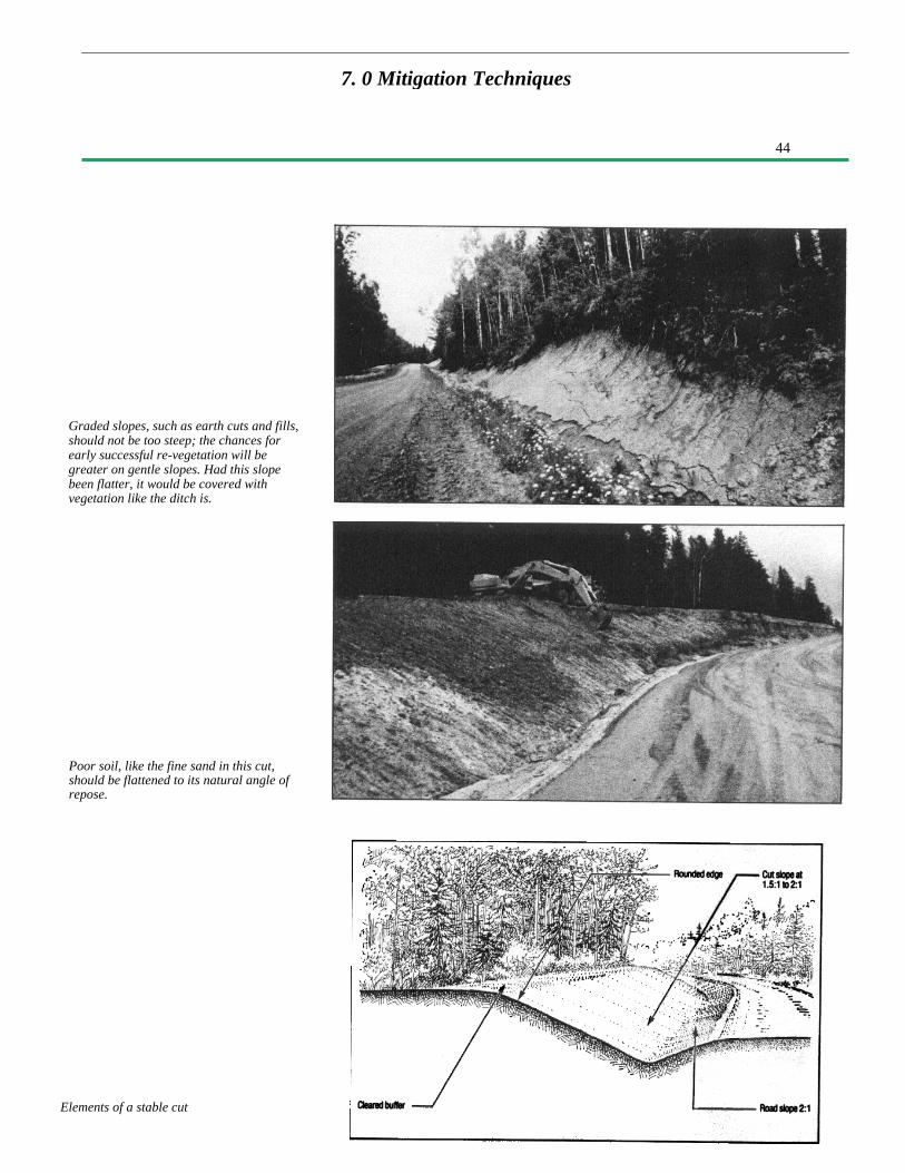
44
Elements of a stable cut
Graded slopes, such as earth cuts and fills,should not be too steep; the chances forearly successful re-vegetation will begreater on gentle slopes. Had this slopebeen flatter, it would be covered withvegetation like the ditch is.
Poor soil, like the fine sand in this cut,should be flattened to its natural angle ofrepose.
7. 0 Mitigation Techniques
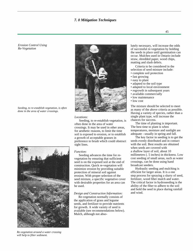
45
7. 0 Mitigation Techniques
Erosion Control UsingRe-Vegetation
Seeding, to re-establish vegetation, is oftendone in the area of water crossings.
Re-vegetation around a water crossingwill help to filter sediment.
Locations:Seeding, to re-establish vegetation, is
often done in the area of watercrossings. It may be used in other areas,for aesthetic reasons, to limit the timesoil is exposed to erosion, or to establisha growth of acceptable grasses inpreference to brush which could obstructsight lines.
Function:Seeding advances the time for re-
vegetation by ensuring that sufficientseed is on the exposed soil at the end ofconstruction. Quick re-vegetation willminimize erosion by providing suitableprotection of mineral soil againsterosion. With proper selection of theseed mixture, a specific vegetative coverwith desirable properties for an area canbe used.
Design and Construction Information:Re-vegetation normally consists of
the application of grass and legumeseeds, and fertilizer to provide nutrientsfor growth. A wide variety of seed isavailable (see recommendations below).Mulch, although not abso-
lutely necessary, will increase the oddsof successful re-vegetation by holdingthe seeds in place until germination canoccur. Mulches used in Ontario includestraw, shredded paper, wood chips,matting and slash debris.
Criteria to be considered in theselection of seed mixture include:• complete soil protection• fast growing• easy to plant• adapted to the soil type• adapted to local environment• regrowth in subsequent years• available commercially• low maintenance• low cost
The mixture should be selected to meetas many of the above criteria as possible.Having a variety of species, rather than asingle plant type, will increase thechances for success.
The time of planting is important.The best time to plant is whentemperatures, moisture and sunlight areadequate - usually in spring and fall.
The key factor in seeding is to get theseeds evenly distributed and in contactwith the soil. Best results are obtainedwhen seeds are covered witha shallow layer of soil, about 10millimetres (. 5 inches) in thickness. Lowcost seeding of small areas, such as watercrossings, can be done using handbroadcast seeders.
Hydraulic seeding and mulching isefficient for larger areas. It is a onestep process for spraying a slurry of seed,fertilizer, wood fiber mulch and water.The critical factor in hydroseeding is theability of the fiber to adhere to the soiland hold the seed in place during rainfalland wind.

46
322018101055
7.0 Mitigation Techniques
Sandy, Infertile Sites with LittleTopsoil
Loamy to Clayey, More Fertile
Fertilizer is essential to theestablishment of vegetation, particularlywhere organic soil has been removed ingrubbing. The key elements are nitrogen,phosphorus, potassium and sulphur. Theamount and type of fertilizer depends onlocal soil and water conditions.
The use of shrubs, trees and otherlive plantings along water ways or lakeshores may be desirable for aesthetic or
other purposes, such as shading.Techniques are also available for usinglive and dead plant material for erosionand sediment control. Such techniquesare known as "bio-engineering"; theseare characterized by low material andequipment costs, but they are quitelabour intensive. Information on thesemethods is contained in the referenceslisted in Section 9.
Grass Seed Mixtures and Fertilizer Recommended For Northern Ontario
Per AcreMaterialsNorlea Perennial RyeGrassBirdsfoot Trefoil (inocu-lated seed)*Canada bluegrassTall fescueCreeping red fescueCreeping foxtail (coated)Biljart hard fescueAlsike Clover8-32-16 standard fertilizermixture0-40-0 super phosphatefertilizer0-0-60 muriate of potash
Per Hectare
25 kg.
kg.kg.kg.kg.kg.kg.kg.
350 kg.
22 lb.
200 kg.200 kg.
2818169955
lb.lb.lb.lb.lb.lb.lb.
310 lb.
180 lb.180 lb.
*Do not use in farming areas
MaterialsAlsike cloverCreeping red fescueCanada bluegrassPerennial ryeWhite clover8-32-16 fertilizer
Per Hectare20 kg.55 kg.27 kg.15 kg.3 kg.
350 kg.
Per Acre18 lb.50 lb.24 lb.14 lb.
3 lb.312 lb.
Source: Ontario Ministry of Transportation, Maintenance Branch.
Disadvantages:Stimulation of re-vegetation by seed and mulch applications is quite expensiveand, except near water courses, the benefits of quicker re-vegetation than wouldoccur naturally may not justify its use on most access roads.
Approximate Cost (1987 dollars)For broadcast seeding:For Hydroseed andwood fibre mulch:
$1,150 per hectare ($460 per acre)
$3,000 per hectare ($1,200 per acre)

47
7.0 Mitigation Techniques
Erosion Control Using Check Dam
Two types of check dams
Locations:Check dams are used in ditches to
create an overflow weir that slowsdown velocity, thus reducing ditchlineerosion. They may be either temporary,until vegetation is established, orpermanent. The drainage area of theditch being protected should not exceedfour hectares (10 acres).
Function:Check dams prevent channel erosion
by maintaining low flow velocities andcatching sediment. Runoff is steppeddown the sloping ditch at check damlocations where erosion resistantmaterial is provided.
Design and Construction Information:Check dams can be constructed using
virtually any material available on site,such as logs, shot rock, boulders,sandbags, gabions, wood planks or othererosion resistant material.
They are constructed by placingselected material across the ditchchannel normal to the flow. It isimportant to properly embed the dam toprevent undercutting by flow under thedam.
The weir size must be adequate toprevent washing around the edgesthrough the native soil.
The maximum height of a checkdam should be less than 600 millimetres(two feet) and the centre should be atleast 150 millimetres (six inches) lowerthan the outer edges. The spacing ofcheck dams in a ditch should be closeenough to control flow velocity.
Disadvantages:Close spacing on steep grades is
required. Frequent clean-out is neededfor best performance. Unless properlydesigned and keyed at the side andbottom, erosion around the edges mayoccur. If the dam washes out, it maycause more sedimentation downstreamthan would have occurred if the checkdam had not been used.
Approximate Cost (1987 dollars): Assuming suitable boulder
material is available within a 10kilometre (six mile) haul, anapproximate cost would be $200 perdam.
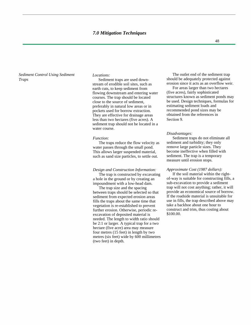
48
Sediment Control Using SedimentTraps
7.0 Mitigation Techniques
Locations:Sediment traps are used down-
stream of erodible soil sites, such asearth cuts, to keep sediment fromflowing downstream and entering watercourses. The trap should be locatedclose to the source of sediment,preferably in natural low areas or inpockets used for borrow extraction.They are effective for drainage areasless than two hectares (five acres). Asediment trap should not be located in awater course.
Function:The traps reduce the flow velocity as
water passes through the small pond.This allows larger suspended material,such as sand size particles, to settle out.
Design and Construction Information:The trap is constructed by excavating
a hole in the ground or by creating animpoundment with a low-head dam.
The trap size and the spacingbetween traps should be selected so thatsediment from expected erosion areasfills the traps about the same time thatvegetation is re-established to preventfurther erosion. Otherwise, periodic re-excavation of deposited material isneeded. The length to width ratio shouldbe 2:1 or larger. A typical trap for a twohectare (five acre) area may measurefour metres (15 feet) in length by twometres (six feet) wide by 600 millimetres(two feet) in depth.
The outlet end of the sediment trapshould be adequately protected againsterosion since it acts as an overflow weir.
For areas larger than two hectares(five acres), fairly sophisticatedstructures known as sediment ponds maybe used. Design techniques, formulas forestimating sediment loads andrecommended pond sizes may beobtained from the references inSection 9.
Disadvantages:Sediment traps do not eliminate all
sediment and turbidity; they onlyremove large particle sizes. Theybecome ineffective when filled withsediment. The trap is a temporarymeasure until erosion stops.
Approximate Cost (1987 dollars):If the soil material within the right-
of-way is suitable for constructing fills, asub-excavation to provide a sedimenttrap will not cost anything; rather, it willprovide an economical source of borrow.If the roadside material is unsuitable foruse in fills, the trap described above maytake a backhoe about one hour toconstruct and trim, thus costing about$100.00.
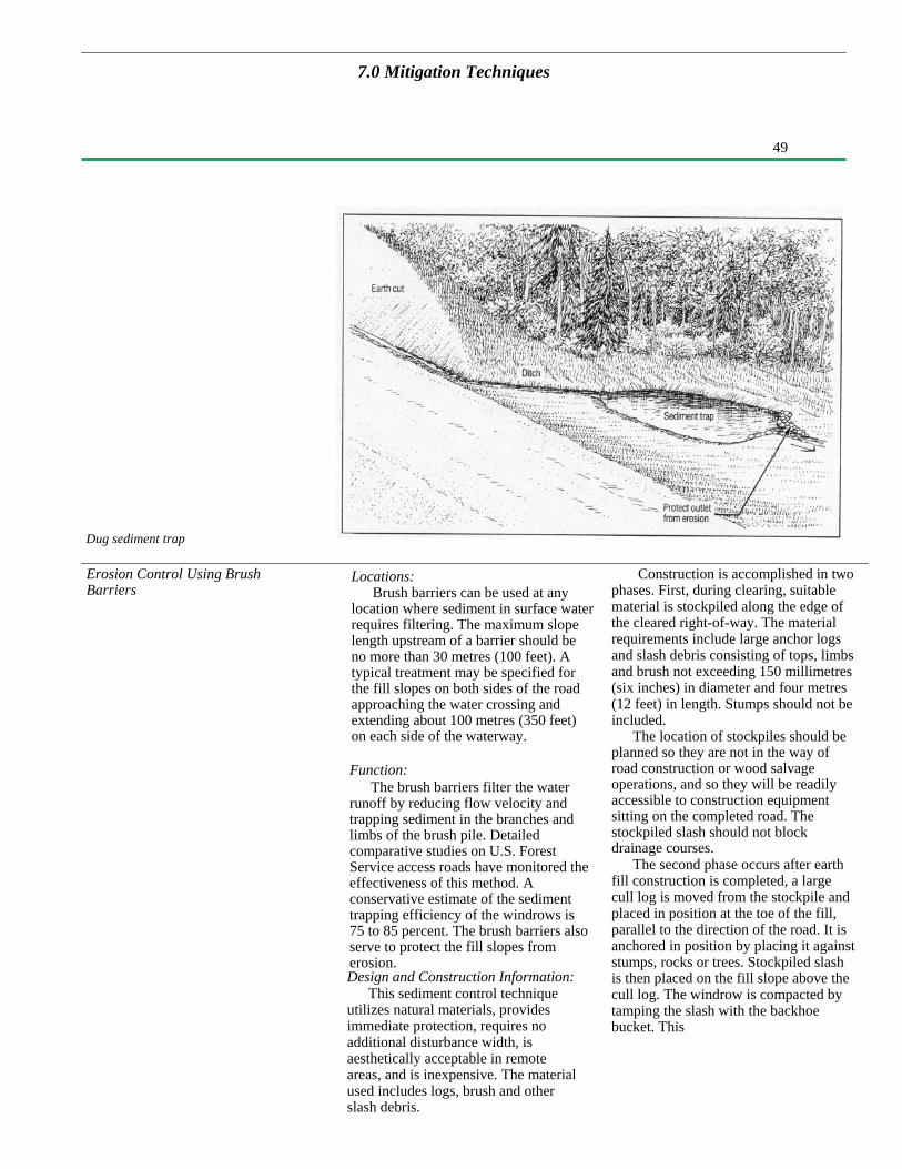
49
7.0 Mitigation Techniques
Dug sediment trap
Erosion Control Using BrushBarriers
Locations:Brush barriers can be used at any
location where sediment in surface waterrequires filtering. The maximum slopelength upstream of a barrier should beno more than 30 metres (100 feet). Atypical treatment may be specified forthe fill slopes on both sides of the roadapproaching the water crossing andextending about 100 metres (350 feet)on each side of the waterway.
Function:The brush barriers filter the water
runoff by reducing flow velocity andtrapping sediment in the branches andlimbs of the brush pile. Detailedcomparative studies on U.S. ForestService access roads have monitored theeffectiveness of this method. Aconservative estimate of the sedimenttrapping efficiency of the windrows is75 to 85 percent. The brush barriers alsoserve to protect the fill slopes fromerosion.Design and Construction Information:
This sediment control techniqueutilizes natural materials, providesimmediate protection, requires noadditional disturbance width, isaesthetically acceptable in remoteareas, and is inexpensive. The materialused includes logs, brush and otherslash debris.
Construction is accomplished in twophases. First, during clearing, suitablematerial is stockpiled along the edge ofthe cleared right-of-way. The materialrequirements include large anchor logsand slash debris consisting of tops, limbsand brush not exceeding 150 millimetres(six inches) in diameter and four metres(12 feet) in length. Stumps should not beincluded.
The location of stockpiles should beplanned so they are not in the way ofroad construction or wood salvageoperations, and so they will be readilyaccessible to construction equipmentsitting on the completed road. Thestockpiled slash should not blockdrainage courses.
The second phase occurs after earthfill construction is completed, a largecull log is moved from the stockpile andplaced in position at the toe of the fill,parallel to the direction of the road. It isanchored in position by placing it againststumps, rocks or trees. Stockpiled slashis then placed on the fill slope above thecull log. The windrow is compacted bytamping the slash with the backhoebucket. This

50
7.0 Mitigation Techniques
Brush barrier at toe of hill
Sediment Control Using Slit Fences
produces a relatively dense windrowembedded in the fill surface. It isimportant that the slash be embedded toprevent flow under it.
In addition to use on the toe ofslopes, slash debris can be used toreduce erosion and sediment transportfrom any area of erodible soil. Slashdebris can be spread over the exposedmineral soil and then trampled into placeusing tracked construction equipment.
Disadvantages:Some people view the presence of
logs and brush along the roadside as
being aesthetically offensive. If notproperly anchored and embedded inthe slope, the brush material may beineffective and could come loose toblock ditches or culverts.
Approximate Cost (1987 dollars):Studies have shown that a track-
mounted Caterpillar 235 backhoe wasable to construct windrows at a rate of52 metres per hour (170 feet per hour)(from Cook and King). This wouldequate to $0.65 per lineal foot treated.This figure does not count the costsavings in not having to dispose of thebrush in push-outs.
Locations:Silt fences are installed to collect
sediment from small areas duringconstruction. Typically, they would bebuilt at the toe of an embankment slope,along the bank of a sensitive stream, orat the downstream end of an erodibleearth cut area. The maximum slopelength behind the barrier should be nomore than 30 metres (100 feet), and itshould be no steeper than 2:1.
Function:Silt fences act like a strainer; silt and
sand are trapped on the surface of thefence while water passes through. Siltfences also reduce the velocity of sheetflow and thereby induce the depositionof sediment.
Design and Construction Information:Silt fences are relatively inexpensive
filtering devices in the form ofpermeable or semi-permeable fences ordams.
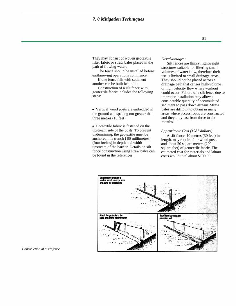
51
7. 0 Mitigation Techniques
Construction of a silt fence
They may consist of woven geotextilefilter fabric or straw bales placed in thepath of flowing water.
The fence should be installed beforeearthmoving operations commence.
If one fence fills with sedimentanother can be built behind it.
Construction of a silt fence withgeotextile fabric includes the followingsteps:
• Vertical wood posts are embedded inthe ground at a spacing not greater thanthree metres (10 feet).
• Geotextile fabric is fastened on theupstream side of the posts. To preventundermining, the geotextile must beanchored in a trench I 00 millimetres(four inches) in depth and widthupstream of the barrier. Details on siltfence construction using straw bales canbe found in the references.
Disadvantages:Silt fences are flimsy, lightweight
structures suitable for filtering smallvolumes of water flow, therefore theiruse is limited to small drainage areas.They should not be placed across adrainage path that carries high-volumeor high velocity flow where washoutcould occur. Failure of a silt fence due toimproper installation may allow aconsiderable quantity of accumulatedsediment to pass down-stream. Strawbales are difficult to obtain in manyareas where access roads are constructedand they only last from three to sixmonths.
Approximate Cost (1987 dollars):A silt fence, 10 metres (30 feet) in
length, may require four wood postsand about 20 square meters (200square feet) of geotextile fabric. Theestimated cost for materials and labourcosts would total about $100.00.

52
7.0 Mitigation Techniques
Sediment Control Using ForestFloor Filter
Diversion of run-off into the forest willmake use of the forest floor as a naturalfilter medium to trap sediment.
Locations:The forest floor adjacent to the right-
of-way provides a natural sediment filterat virtually any location on thedownstream side of the road. Use of thisnatural filter is particularly importantnear water crossings, so that turbidrunoff does not flow down the ditch andstream banks into the water directly.The drainage area upstream of thediversion berm should be less than twohectares (five acres).
Function:The natural forest floor, with its litter
and vegetative material, can be used toserve as a filter medium to trap sedimentbefore it reaches a water course.
Design and Construction Information:This treatment may require
construction of an earth diversion bermacross the ditch line, and excavation of achannel to carry water to the edge of theright-of-way. A diversion berm isdifferent from a check dam because
water is diverted out of the ditch and notallowed to flow over the berm. Whereused, it is important to check that thewater will, in fact, drain away from theright-of-way at a slope of at least onepercent. Berms should have a top widthand height of at least 500 millimetres (20inches) and side slopes of 2:1 or flatter.Since the diversion berm will beredirecting flowing water, the upstreamsurface should be resistant to erosionfrom the expected flow velocities.
The recommended spacingbetween ditch outlets depends on theslope of the ditch and the erodibility ofthe soil; refer to Table 1 in Section 5.7.
The length of forest floor requiredfor effective filtering and sedimententrapment is generally recommended as30 metres (100 feet) for slopes less than15 percent, and up to 90 metres (300feet) on steeper slopes.

53
7.0 Mitigation Techniques
Diversion berms can be used to redirectflow off right-of- way
7.3 Beaver Problems
Disadvantages:Ditch channel, berm size and outlet
channel must be of adequate size tohandle expected flow, including floodflows. If not properly sized, the bermwill overtop and flow will continuedown the ditch line.
Approximate Cost:A nominal cost may be incurred to
construct the berms and provide off-take channels, however this would beoffset by a savings in downstream ditchsize and elimination of the possible needfor erosion protection.
Road culverts are ideal sites for beaversto construct dams for backing up waterand creating habitat. Blockage ofculverts by direct beaver activity, andthe failure of beaver dams that cause thesudden release of water, have led tomany road washouts. There are twotypes of action that may be taken tominimize the problem:
(a) Special Design Techniques:In new construction taking place in
beaver areas, the use of larger culvertpipe diameters will tend to make damconstruction more difficult. Batteryoperated electric wire fences, such asthose used for farm animals, have alsobeen successful in discouraging beaveractivity by giving them an electricalshock at the culvert inlet.
Devices can be installed upstream ofthe culvert inlet to prevent damconstruction in the pipe itself. Bedsprings
have been used for years as a screen.More sophisticated attachments include awire mesh culvert protector that is athree metre (10 foot) upstream extensionof the culvert, made of heavy wire meshrolled to the diameter of the culvert.Patented culvert attachments are alsoavailable from several suppliers. Thesedevices attract the beaver to build in acertain location where periodic removalof debris is not as difficult as from insidea pipe. Some of the attachments must beremoved to ensure free flow of waterduring flood periods. As long as thebeaver is active in the area of the culvert,maintenance will be required.
(b) Beaver Removal:If the above methods are
unsatisfactory or undesirable, it isrecommended that, through the Ministry,the services of the local licensed trapper
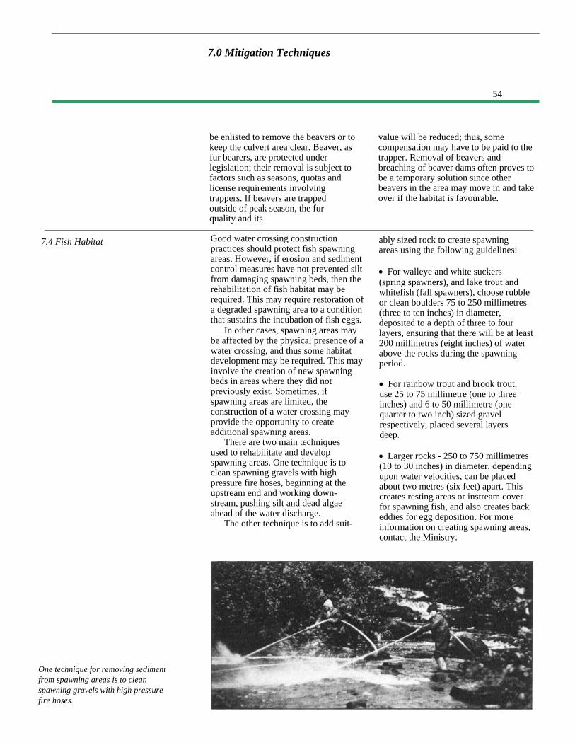
54
One technique for removing sedimentfrom spawning areas is to cleanspawning gravels with high pressurefire hoses.
7.0 Mitigation Techniques
be enlisted to remove the beavers or tokeep the culvert area clear. Beaver, asfur bearers, are protected underlegislation; their removal is subject tofactors such as seasons, quotas andlicense requirements involvingtrappers. If beavers are trappedoutside of peak season, the furquality and its
7.4 Fish Habitat Good water crossing constructionpractices should protect fish spawningareas. However, if erosion and sedimentcontrol measures have not prevented siltfrom damaging spawning beds, then therehabilitation of fish habitat may berequired. This may require restoration ofa degraded spawning area to a conditionthat sustains the incubation of fish eggs.
In other cases, spawning areas maybe affected by the physical presence of awater crossing, and thus some habitatdevelopment may be required. This mayinvolve the creation of new spawningbeds in areas where they did notpreviously exist. Sometimes, ifspawning areas are limited, theconstruction of a water crossing mayprovide the opportunity to createadditional spawning areas.
There are two main techniquesused to rehabilitate and developspawning areas. One technique is toclean spawning gravels with highpressure fire hoses, beginning at theupstream end and working down-stream, pushing silt and dead algaeahead of the water discharge.
The other technique is to add suit-
value will be reduced; thus, somecompensation may have to be paid to thetrapper. Removal of beavers andbreaching of beaver dams often proves tobe a temporary solution since otherbeavers in the area may move in and takeover if the habitat is favourable.
ably sized rock to create spawningareas using the following guidelines:
• For walleye and white suckers(spring spawners), and lake trout andwhitefish (fall spawners), choose rubbleor clean boulders 75 to 250 millimetres(three to ten inches) in diameter,deposited to a depth of three to fourlayers, ensuring that there will be at least200 millimetres (eight inches) of waterabove the rocks during the spawningperiod.
• For rainbow trout and brook trout,use 25 to 75 millimetre (one to threeinches) and 6 to 50 millimetre (onequarter to two inch) sized gravelrespectively, placed several layersdeep.
• Larger rocks - 250 to 750 millimetres(10 to 30 inches) in diameter, dependingupon water velocities, can be placedabout two metres (six feet) apart. Thiscreates resting areas or instream coverfor spawning fish, and also creates backeddies for egg deposition. For moreinformation on creating spawning areas,contact the Ministry.
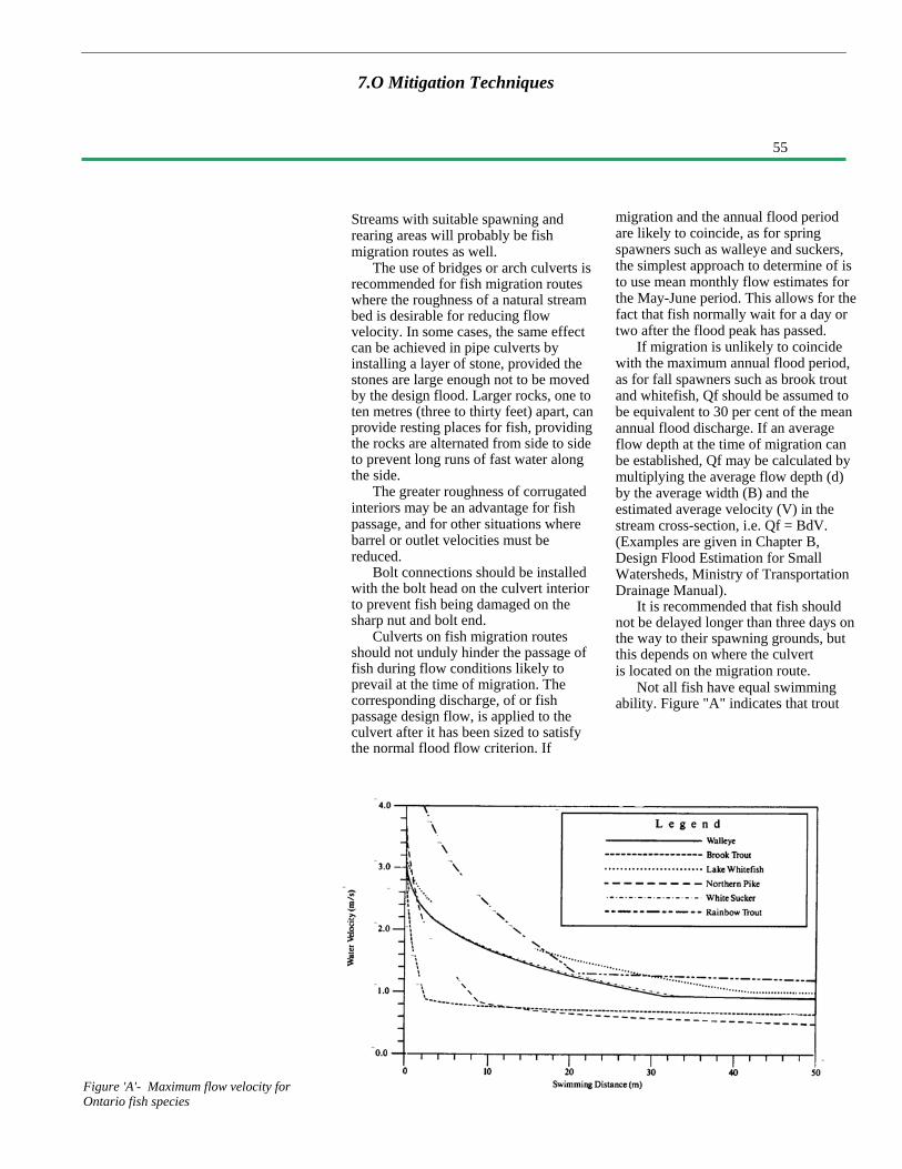
55
7.O Mitigation Techniques
Figure 'A'- Maximum flow velocity forOntario fish species
Streams with suitable spawning andrearing areas will probably be fishmigration routes as well.
The use of bridges or arch culverts isrecommended for fish migration routeswhere the roughness of a natural streambed is desirable for reducing flowvelocity. In some cases, the same effectcan be achieved in pipe culverts byinstalling a layer of stone, provided thestones are large enough not to be movedby the design flood. Larger rocks, one toten metres (three to thirty feet) apart, canprovide resting places for fish, providingthe rocks are alternated from side to sideto prevent long runs of fast water alongthe side.
The greater roughness of corrugatedinteriors may be an advantage for fishpassage, and for other situations wherebarrel or outlet velocities must bereduced.
Bolt connections should be installedwith the bolt head on the culvert interiorto prevent fish being damaged on thesharp nut and bolt end.
Culverts on fish migration routesshould not unduly hinder the passage offish during flow conditions likely toprevail at the time of migration. Thecorresponding discharge, of or fishpassage design flow, is applied to theculvert after it has been sized to satisfythe normal flood flow criterion. If
migration and the annual flood periodare likely to coincide, as for springspawners such as walleye and suckers,the simplest approach to determine of isto use mean monthly flow estimates forthe May-June period. This allows for thefact that fish normally wait for a day ortwo after the flood peak has passed.
If migration is unlikely to coincidewith the maximum annual flood period,as for fall spawners such as brook troutand whitefish, Qf should be assumed tobe equivalent to 30 per cent of the meanannual flood discharge. If an averageflow depth at the time of migration canbe established, Qf may be calculated bymultiplying the average flow depth (d)by the average width (B) and theestimated average velocity (V) in thestream cross-section, i.e. Qf = BdV.(Examples are given in Chapter B,Design Flood Estimation for SmallWatersheds, Ministry of TransportationDrainage Manual).
It is recommended that fish shouldnot be delayed longer than three days onthe way to their spawning grounds, butthis depends on where the culvertis located on the migration route.
Not all fish have equal swimmingability. Figure "A" indicates that trout
56
7.0 Mitigation Techniques
7.5 Aesthetics
can handle higher velocities than pike.Swimming ability is also based on fishsize. Normally larger fish can handlehigher velocities better than smallerones, but smaller fish may be able to usethe zones of lower velocity water nearthe bottom or sides in culverts; thisfactor may obscure the relationshipbetween swimming ability and fishlength. The graph shown as Figure "A"may be applied to culverts using themean water velocity at the fish passagedesign flow (Qf) and the culvert lengthas the swimming distance.
Slope is the most important factordetermining water velocities in culverts
Although the scope of theseenvironmental guidelines is intended todeal primarily with the physicalenvironment affected by access roadconstruction, a brief discussion ofaesthetics is warranted becauseappearances affect people's attitudes.
In the construction of highways andstreets in Ontario, aesthetics represent animportant consideration. These roads arepart of the environment in which peoplelive; many spend a measurableproportion of their time travelling onthem. Aesthetics, or the appearance of aroadside environment, is a personalsubjective matter.
Traffic volumes on the highwaysystem are relatively high whencompared to access roads in "the bush".Average traffic on an access roadconstructed for timber managementactivities might reach 50 vehicles perday during the most active harvestingperiod, and drop to perhaps five vehiclesper day after harvesting. For this reason,the benefits of improved aesthetics onaccess roads do not usually justify thehigh cost of landscaping the roadsideenvironment to make it pleasing to theeye.
Current practice is to identify, duringthe road planning phase, those roads andwork areas that should be constructed toa higher aesthetic standard of appearancethan is considered necessary to protectthe physical
at lower flows. Keeping the culvertgradients as flat as possible willencourage fish migration. If the fishvelocity criterion cannot be met bymodifying the culvert design, baffles,which create resting areas at intervalsalong the culvert, can enable fish topass through. Offset baffles are themost commonly used type: these aredescribed in the Ontario Ministry ofTransportation Drainage Manual(Chapter D, Sec. 2-10.2).
For design information on culvertfishways, refer to the references listedin Section 9.
environment. For example, a majoraccess corridor that will carry long-term,multiple-use traffic could be identified asrequiring special attention for aesthetics.Action required to improve theappearance of a road must be measuredagainst other factors, such as a greaterimpact on the physical environment,increased construction costs, or areduction in safety for road users.
For example, the disposal of slashdebris on roadside slopes and ditch areashas been shown to reduce soil erosionand downstream sedimentation by asmuch as 85 percent. This practice iseconomical and environmentally sound.However, the appearance of brush, logsand stumps windrowed along the edge ofthe roadway does not appeal to thegeneral public's perception of what a"good" road should look like. Mostpeople would prefer to look at a roadsidewhere grubbing material is placed inpush-outs, although this practice removesorganic material from the right-of-way,exposes soil to erosion and takes in alarger surface area for road constructionactivities.
Another example would be theintentional placement of curves on theapproach to a single lane bridge tolimit view of the road from the river.

57
7.0 Mitigation Techniques
Although providing aesthetic benefits,the action will reduce safety for driversand pedestrians.
As these examples illustrate, theguidelines for aesthetics should not beimplemented unless there is anidentified need. As part of the decision-making process, the additional cost oftaking special measures for aestheticsshould be determined and weighedagainst the benefit.
Good Practices - Aesthetics• Cut, skid and pile non-merchantablespecies of timber in landings outside theright-of-way.
• Dispose of grubbing material in pre-cut push-outs off the right-of-way. Thepush-outs should be angled away fromthe direction of traffic on that side of theroad. They should be trampled flat, withno logs protruding, and covered withorganic material to present a neatappearance.
• Seed and mulch the right-of-wayfrom the clearing limit to the edge ofshoulder.
• In the design of a water crossing, thevisual impact from the waterway maybe a consideration. Design techniquesavailable include the followingconsiderations:
- The physical location andduration of time a structure is inview can mitigate the aestheticimpact of a crossing.
- If possible, locate the rivercrossing away from attractivescenic areas. This may meanmoving from a good constructionsite at a rapids to a more difficultnon-rapids location.
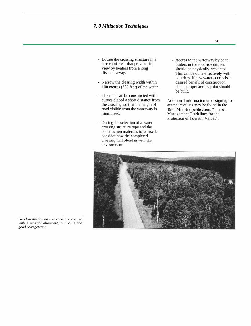
58
7. 0 Mitigation Techniques
Good aesthetics on this road are createdwith a straight alignment, push-outs andgood re-vegetation.
- Locate the crossing structure in astretch of river that prevents itsview by boaters from a longdistance away.
- Narrow the clearing width within100 metres (350 feet) of the water.
- The road can be constructed withcurves placed a short distance fromthe crossing, so that the length ofroad visible from the waterway isminimized.
- Access to the waterway by boattrailers in the roadside ditchesshould be physically prevented.This can be done effectively withboulders. If new water access is adesired benefit of construction,then a proper access point shouldbe built.
Additional information on designing foraesthetic values may be found in the1986 Ministry publication, "TimberManagement Guidelines for theProtection of Tourism Values".
- During the selection of a watercrossing structure type and theconstruction materials to be used,consider how the completedcrossing will blend in with theenvironment.

59
8. 0 Glossary of Terms
Abutment: The structure supportingthe ends of a bridge and retaining theapproach fills. (See sketch)
Access road: A road constructed by thepublic or private sector on Crown landunder the authority of the Public LandsAct. These low volume roads generallyhave a gravel surface.
Alignment: The horizontal route ordirection of an access road. It is madeup of straight line tangent sections andcurves.
Angle of Repose: The maximum slopeor angle at which a material such as soilor loose rock remains stable.
Apron: Erosion protection placed belowthe stream bed in an area of high flowvelocity, such as downstream of aculvert.
Bailey Bridge: A patented pre-fabricatedtype of bridge used since 1942 on lowvolume roads. A variety of bridgelengths and configurations can beassembled from standard componentsand the unit can be 'launched' intoposition.
Berm: A low earth fill constructed inthe path of flowing water to divert itsdirection, or constructed to act as acounter-weight beside the road fill toreduce the risk of foundation failure.
Camber: The vertical rise in profile, orhump, such as at the centre of a culvertbedding, which allows for anticipateddownward deflection.
Check Dam: A low head dam structureconstructed in a ditch in the path offlowing water to reduce erosion. Waterflows over a check dam, so it isprovided with a spill-over section thatis erosion-resistant.
Cofferdam: A temporary enclosure builtin a watercourse and pumped dry topermit work on bridge abutments orpiers, thereby separating the work areafrom the water.
Corduroy: Logs placed over a swampto reinforce the natural root mat for thepurpose of minimizing the risk ofsettlement or foundation failure.
Crown: A road is 'crowned' when thecentre of the road surface is higher thanits outer edges to create a cross-gradient of about four percent. Thisenables water on the surface to draintowards the ditches. (See sketch)
Culvert, CSP: Corrugated steel pipe isthe common material used for culvertsto convey water under an access road.The term refers to the factory-assembledround shapes connected together withcouplers.
Culvert, Multi-plate: Multi-plate orstructural plate culverts are thosewhich, due to their large diameter(usually over 1800 millimetres [sixfeet]), are normally field-assembled inplace. A series of interlocking steelplates are bolted together to make therequired shape and length.
Fish Habitat: Resources and conditionsessential for the production of fish,including water quality and quantity,spawning grounds, nursery, rearing,food supply and migration areas onwhich fish depend, directly or indirectly,for their life processes.
Foundation: The foundation for abridge may include the underlyingsoil and the lowest levels of anypier or abutment resting on it.(See sketch)

60
Gabion: A patented woven wire basketfilled with stones of minimum size thatwill not pass through the openings in thebasket. Individual baskets are laid inplace like building blocks, and thenfilled to form retaining walls anderosion-resistant surfaces.
Geo-grid: A recently-developedproduct used as a soil reinforcementagent. It is made of polyethylene and issupplied in rolls about two metres (sixfeet) wide. The product has openingssimilar to security fencing.
Geometric Road Standard: Engineeringparameters that define the geometry of aparticular road cross-section, alignmentand profile grade, are called thegeometric road standard. Access roadsare generally built to conform with acertain minimum geometric roadstandard; the higher the standard, thehigher the safe travel speed will be.
Geotextile: A recently-developedproduct used as a soil reinforcementagent and as a filter medium. It is madeof synthetic fibres manufactured in awoven or loose non-woven manner toform a blanket-like product. It isnormally supplied in rolls that wouldcover four metres wide by 100 metreslong (15 by 300 feet).
Grade or Profile Grade: The elevationof the top of the finished road is calledgrade or profile grade. The longitudinalcross-section of a road showing theelevation at various points along thelength of a road is called the roadprofile.
Gravel, Pit-Run: The name given tonaturally occurring graded materialdeposited by the retreating glaciers inflowing water (kames, eskers, spill-ways). Gravel is a granular materialranging in size from fine sand to about50 millimetres (two inches) in diameter.
Landing: An area where cut timber ispiled before slashing and/or haulage.
Off-take Ditch: A ditch excavated tocarry roadside drainage away from theroadway to a point downstream and offthe right-of-way to which waterwill flow. In flat terrain an off-take ditchmay extend into the bush outside theright-of-way.
Pier: On bridges of more than onespan, the intermediate supportsbetween abutments are called piers.
Profile Grade: See 'grade'. (Seesketch)
Push-out: Areas where slash debris,stumps and organic material aredeposited in piles off the right-of-way.
Qf: The quantity of flow to be usedwhen determining flow velocitiesduring fish migration periods.
Right-of-way: The cleared area alongthe road alignment which contains theroadbed, ditches, road slopes and backslopes. (See sketch)
Rip Rap: A layer of boulders or shotrock fragments placed over a soil toprotect it from the erosive forces offlowing water. (See sketch)
Scour: This is the term used to describesoil erosion when it occurs under water,as in the case of a stream bed or riverbottom.
Shear-blading: The operation of cut-ting off trees and brush at ground levelby pushing a bulldozer blade along thefrozen surface in winter. The stems andtrunks are sheared off at ground level.
Subgrade: In a vertical cross-section of aroad, the subgrade is the surface of theearth cut or earth fill before theplacement of selected imported materialto construct a sand cushion or gravelsurface. (See sketch)
8.0 Glossary of Terms
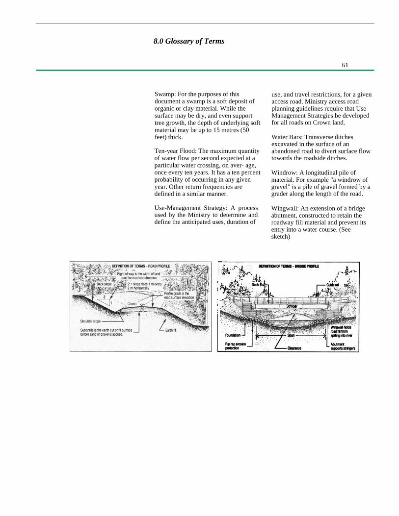
61
8.0 Glossary of Terms
Swamp: For the purposes of thisdocument a swamp is a soft deposit oforganic or clay material. While thesurface may be dry, and even supporttree growth, the depth of underlying softmaterial may be up to 15 metres (50feet) thick.
Ten-year Flood: The maximum quantityof water flow per second expected at aparticular water crossing, on aver- age,once every ten years. It has a ten percentprobability of occurring in any givenyear. Other return frequencies aredefined in a similar manner.
Use-Management Strategy: A processused by the Ministry to determine anddefine the anticipated uses, duration of
use, and travel restrictions, for a givenaccess road. Ministry access roadplanning guidelines require that Use-Management Strategies be developedfor all roads on Crown land.
Water Bars: Transverse ditchesexcavated in the surface of anabandoned road to divert surface flowtowards the roadside ditches.
Windrow: A longitudinal pile ofmaterial. For example "a windrow ofgravel" is a pile of gravel formed by agrader along the length of the road.
Wingwall: An extension of a bridgeabutment, constructed to retain theroadway fill material and prevent itsentry into a water course. (Seesketch)

62
Environmental Guidelines forResource Road Construction,Newfoundland Forest ResearchCentre, Canadian Forestry Service,Environment Canada, 1978.
Ontario Government Publications:
Other Canadian Publications:
Guidelines and Criteria for ApprovalUnder the Lakes and RiversImprovement Act, Ontario Ministry ofNatural Resources, 1977.
Highway Construction Practices andPotential Environmental Concerns,Ontario Ministry of Transportation andCommunications, 1978.
Class Environmental Assessment forAccess Roads to MNR Facilities,Ontario Ministry of Natural Resources,1984.
Community Fisheries InvolvementProgram Field Manual, Part One: TroutStream Rehabilitation, OntarioMinistry of Natural Resources, 1984.
Evaluating Construction ActivitiesImpacting on Water Resources, Part 11 -Guidelines for Construction ofHighways and Bridges, Ontario Ministryof the Environment, 1984.
Resource Access Roads, Policy andImplementation Strategies andGuidelines, Ontario Ministry of NaturalResources, 1985.
Turf Establishment Manual, OntarioMinistry of Transportation andCommunications, 1986.
Evaluation of the swimmingperformance of several fish speciesfrom the MacKenzie River, D.R.Jones, J.W., Kiceniuk and O. S.Bamford, Journal Fisheries ResearchBoard of Canada, Volume 31: 1641-1647, 1974.
Timber Management Guidelines forthe Protection of Tourism Values,Ontario Ministry of NaturalResources, 1986.
Class Environmental Assessment forTimber Management on Crown Lands inOntario, Ontario Ministry of NaturalResources, 1985, revised 1987.
Rehabilitation of Pits and Quarries forFish and Wildlife, Ontario Ministry ofNatural Resources, 1987.
Sand and Gravel Pit Rehabilitation inNorthern Ontario, Ontario Ministry ofNatural Resources, 1987.
Guidelines on Erosion and SedimentControl for Urban Construction Sites,Ontario Urban DrainageImplementation Committee, 1987.
Timber Management Guidelines forthe Protection of Fish Habitat, OntarioMinistry of Natural Resources, 1988.
Timber Management Guidelines forthe Provision of Moose Habitat,Ontario Ministry of NaturalResources, 1988.
Drainage Manual, Volumes 1, 2 and 3,Ontario Ministry of Transportation,Current.
Watershed Management Guidelines forLogging and Road Construction inAlberta, R.L. Rothwell, Northern ForestResearch Centre, Information ReportNOR-X-208, Canadian Forestry Service,Environment Canada, Edmonton, 1978.
A Study of Model and PrototypeCulvert Baffling for Fish Passage, C.Katopodis, P.R. Robinson and B.G.Sutherland, Environment CanadaFisheries and Marine Service,Technical Report 828, December 1978.
9.0 List of References

63
An Experimental Study of OffsetBaffle Culvert Fishways, N.Rajaratnam, S. Lodewyk and C.Katopodis, Technical Report WRE 87-2, Department of Civil Engineering,University of Alberta, 1987.
Nuisance Beaver Control,Saskatchewan Parks and RenewableResources brochure (undated).
A Handbook for Fish Habitat Protectionon Forest Lands in British Columbia,Toews and Brownlee, FederalDepartment of Fisheries and Oceans,Vancouver, 1981.
United States Publications:
A Review and Resolution of FishPassage Problems at Culvert Sites inBritish Columbia, B.G. Dane,Environment Canada Fisheries andMarine Service Technical Report 810,September 1978.
Liard Highway Hydrology Study, M.M.Dillon Ltd., Canada Department ofIndian and Northern Affairs, Ottawa,June 1979.
Bio-engineering for Land Reclamationand Conservation, Hugo Schiechtl,University of Alberta Press, 1980.
Proceedings of Resource RoadsWorkshops, Whitehorse andYellowknife, March 16-20, 1981,Canadian Environmental ProtectionService, Federal Activities AssessmentBranch, Environment Canada, Ottawa,1981.
Erosion Control on HighwayConstruction, Synthesis of HighwayPractice, National Cooperative HighwayResearch Report (NCHRP), Report 18,Transportation Research Board (TRB),Washington, 1973.
Compendium 9, Control of Erosion,Transportation Technology Supportfor Developing Countries, TRB,Washington, 1979.
Erosion Control During HighwayConstruction, Manual on Principlesand Practices, NCHRP Report 221,TRB, Washington, 1980.
Forest Access Roads, Planning andConstruction Manual, Nova ScotiaDepartment of Lands and Forests,1982.
Erosion and Sediment Control atRoad-Stream Crossings, R.C.Rothwell, The Forestry Chronicle,April 1983.
Handbook of Steel Drainage andHighway Construction Products,Canadian Edition, American Ironand Steel Institute, Washington,1984.
Design of Sedimentation Basins -Synthesis of Highway Practice,NCHRP Report 70, TRB, Washing-ton, 1980.
Construction Cost and Erosion ControlEffectiveness of Filter Windrows onFill Slopes, M. J. Cook and J. G. King,Research Note INT-335, Inter-mountain Forest and RangeExperiment Station, Ogen Utah, U.S.Department of Agriculture, U.S. ForestService, 1983.
9.0 List of References
64
9.0 List of References
Use of Corrugated Plastic DrainageTubing for Controlling Water Levels atNuisance Beaver Sites, K.J. Roblee,New York Fish and Game Journal,Volume 31, Number 1, January 1984.
Erosion and Sediment Control Hand-book, Goldman, Jackson andBursztynsky, McGraw Hill, 1986.
Abilities of Trout to Swim ThroughHighway Culverts, D.A. Belford, M.Se. Thesis, Montana State University,Bozeman, Montana, July 1986.

65
5192(3 k P.R., 88 03 31)ISBN 0-7729-3532-7ISBN 9-7794-2374-7 (electronic)