Embed Size (px)
Citation preview

CY3271-EXP1
Environmental Sensing Kit
Spec. # 001-49259 Rev. *B
Cypress Semiconductor198 Champion Court
San Jose, CA 95134-1709
Phone (USA): 800.858.1810Phone (Intnl): 408.943.2600
http://www.cypress.com

2 CY3271-EXP1 Environmental Sensing Kit, Spec. # 001-49259 Rev. *B
Copyrights
Copyrights
© Cypress Semiconductor Corporation, 2008-2011. The information contained herein is subject to change without notice.Cypress Semiconductor Corporation assumes no responsibility for the use of any circuitry other than circuitry embodied in aCypress product. Nor does it convey or imply any license under patent or other rights. Cypress products are not warrantednor intended to be used for medical, life support, life saving, critical control or safety applications, unless pursuant to anexpress written agreement with Cypress. Furthermore, Cypress does not authorize its products for use as critical componentsin life-support systems where a malfunction or failure may reasonably be expected to result in significant injury to the user.The inclusion of Cypress products in life-support systems application implies that the manufacturer assumes all risk of suchuse and in doing so indemnifies Cypress against all charges.
Any Source Code (software and/or firmware) is owned by Cypress Semiconductor Corporation (Cypress) and is protected byand subject to worldwide patent protection (United States and foreign), United States copyright laws and international treatyprovisions. Cypress hereby grants to licensee a personal, non-exclusive, non-transferable license to copy, use, modify, createderivative works of, and compile the Cypress Source Code and derivative works for the sole purpose of creating custom soft-ware and or firmware in support of licensee product to be used only in conjunction with a Cypress integrated circuit as speci-fied in the applicable agreement. Any reproduction, modification, translation, compilation, or representation of this SourceCode except as specified above is prohibited without the express written permission of Cypress.
Disclaimer: CYPRESS MAKES NO WARRANTY OF ANY KIND, EXPRESS OR IMPLIED, WITH REGARD TO THIS MATE-RIAL, INCLUDING, BUT NOT LIMITED TO, THE IMPLIED WARRANTIES OF MERCHANTABILITY AND FITNESS FOR APARTICULAR PURPOSE. Cypress reserves the right to make changes without further notice to the materials describedherein. Cypress does not assume any liability arising out of the application or use of any product or circuit described herein.Cypress does not authorize its products for use as critical components in life-support systems where a malfunction or failuremay reasonably be expected to result in significant injury to the user. The inclusion of Cypress’ product in a life-support sys-tems application implies that the manufacturer assumes all risk of such use and in doing so indemnifies Cypress against allcharges.
Use may be limited by and subject to the applicable Cypress software license agreement.
FirstTouch™, PSoC Designer™, and Programmable System-on-Chip™ are trademarks and PSoC® is a registered trade-mark of Cypress Semiconductor Corp. All other trademarks or registered trademarks referenced herein are property of therespective corporations.
Flash Code Protection
Cypress products meet the specifications contained in their particular Cypress PSoC Data Sheets. Cypress believes that itsfamily of PSoC products is one of the most secure families of its kind on the market today, regardless of how they are used.There may be methods, unknown to Cypress, that can breach the code protection features. Any of these methods, to ourknowledge, would be dishonest and possibly illegal. Neither Cypress nor any other semiconductor manufacturer can guaran-tee the security of their code. Code protection does not mean that we are guaranteeing the product as "unbreakable."
Cypress is willing to work with the customer who is concerned about the integrity of their code. Code protection is constantlyevolving. We at Cypress are committed to continuously improving the code protection features of our products.

CY3271-EXP1 Environmental Sensing Kit, Spec. # 001-49259 Rev. *B 3
Contents
1. Introduction 5
1.1 Kit Contents .................................................................................................................51.2 Prerequisites................................................................................................................51.3 Additional Learning Resources....................................................................................61.4 Document Revision History .......................................................................................61.5 Documentation Conventions .......................................................................................6
2. Getting Started 72.1 Kit Installation ..............................................................................................................72.2 PSoC Designer ..........................................................................................................112.3 PSoC Programmer ....................................................................................................122.4 Configuring Sense and Control Dashboard ...............................................................132.5 Kit Operation..............................................................................................................18
3. Hardware 193.1 Weather Station Expansion Board.............................................................................193.2 Pigtail Thermistor Expansion Board ..........................................................................21
4. Code Examples 23
4.1 My First Example Project ...........................................................................................234.2 Weather Station Code Example ................................................................................23
4.2.1 Project Objective ............................................................................................234.2.2 Device Configuration......................................................................................244.2.3 Flowchart........................................................................................................254.2.4 Verify Output ..................................................................................................25
4.3 Pigtail Sensor Code Example ....................................................................................304.3.1 Project Objective ............................................................................................304.3.2 Device Configuration......................................................................................314.3.3 Flowchart........................................................................................................324.3.4 Verify Output ..................................................................................................32
5. Sensor Calibration 35
5.1 Overview....................................................................................................................355.1.1 Calibrating Humidity Sensor in Firmware.......................................................36
5.2 Alarms and Data Aggregation Intervals .....................................................................375.3 Data Export ................................................................................................................385.4 Save Configuration ....................................................................................................38
A. Appendix 39A.1 Schematics ................................................................................................................39
A.1.1 Weather Station Board...................................................................................39

4 CY3271-EXP1 Environmental Sensing Kit, Spec. # 001-49259 Rev. *B
Contents
A.1.2 Thermistor Board ...........................................................................................40A.2 Weather Station Board Layout ..................................................................................41
A.2.1 Top Layer.......................................................................................................41A.2.2 Bottom Layer .................................................................................................41A.2.3 Primary Silkscreen.........................................................................................41A.2.4 Secondary Silkscreen ....................................................................................41
A.3 Thermistor Board Layout ...........................................................................................42A.3.1 Top Layer.......................................................................................................42A.3.2 Bottom Layer .................................................................................................42A.3.3 Primary Silkscreen.........................................................................................42A.3.4 Secondary Silkscreen ....................................................................................42
A.4 Bill of Materials ..........................................................................................................43A.4.1 CY3271-EXP1 Weather Station BOM............................................................43A.4.2 CY3271-EXP1 Thermistor BOM ....................................................................44

CY3271-EXP1 Environmental Sensing Kit, Spec. # 001-49259 Rev. *B 5
1. Introduction
Thank you for your interest in the CY3271-EXP1 Environmental Sensing Kit. This is an expansion kitfor the CY3271-PSoC FirstTouch Starter Kit with CyFi Low-Power RF (CY3271-FTRF). The CY3271-EXP1 kit includes two boards: the Weather Station Expansion Board (atmospheric pressure,humidity, temperature, and ambient light) and the Pigtail Thermistor Expansion Board. The Senseand Control Dashboard (SCD) enables users to quickly set up and monitor a wired or wirelesssensor network through an intuitive visual dashboard. The CY3271-EXP1 demonstrates featuressuch as data logging, data aggregation, alarms, and sensor calibration for different sensor types.The CY3271-FTRF kit can be purchased separately at http://www.cypress.com/go/ CY3271-FTRF.
The code examples enable using:
■ The programmable analog and digital blocks of PSoC® to interface to common sensors such as thermistors and ambient light sensors.
■ PSoC Designer™ integrated development environment (IDE) to create embedded designs in two methods: traditional chip level designs that involve writing code and code-free system level designs.
■ PSoC's flexible analog to allow multiple sensors to connect the same internal resources.
1.1 Kit Contents
The CY3271-EXP1 kit hardware consists of the following components:
■ Weather Station Expansion Board
■ Pigtail Thermistor Expansion
■ CY3271-EXP1 kit CD/DVD
❐ PSoC Designer installation file
❐ PSoC Programmer installation file
❐ Bridge Control Panel installation file (packaged along with PSoC Programmer)
❐ Sense and Control Dashboard (SCD)
❐ Code examples
❐ Hardware files
❐ Kit guide
❐ Quick start guide
❐ Release notes
Inspect the contents of the kit. If any parts are missing, contact your nearest Cypress sales office forfurther assistance.
1.2 Prerequisites
The CY3271-FTRF Kit is required to operate this kit. This kit can be purchased separately at http://www.cypress.com/go/CY3271-FTRF.

6 CY3271-EXP1 Environmental Sensing Kit, Spec. # 001-49259 Rev. *B
Introduction
1.3 Additional Learning Resources
Visit http://www.cypress.com for additional learning resources in the form of data sheets, technicalreference manual, and application notes.
■ For more information regarding PSoC Designer functionality and releases:
http://www.cypress.com/go/psocdesigner
■ For more information regarding PSoC Programmer, supported hardware and COM layer:
http://www.cypress.com/go/psocprogrammer
■ For a list of PSoC Designer-related trainings:
http://www.cypress.com/?rID=40543
1.4 Document Revision History
1.5 Documentation Conventions
Table 1-1. Revision History
RevisionPDF Creation
DateOrigin of Change
Description of Change
** 10/07/2008 YUR New Guide
*A 07/07/2011 OWEN
Removed reference to HiTech compiler installation. Installation instructions and screenshots modified to match the latest installer.
Added schematic level block diagrams for hardware and firmware description. Added Appendix.
*B 09/27/2011 RKPM Extensive content updates
Table 1-2. Document Conventions for Guides
Convention Usage
Courier NewDisplays file locations, user entered text, and source code:C:\ ...cd\icc\
ItalicsDisplays file names and reference documentation:Read about the sourcefile.hex file in the PSoC Designer User Guide.
[Bracketed, Bold]Displays keyboard commands in procedures:[Enter] or [Ctrl] [C]
File > OpenRepresents menu paths:File > Open > New Project
BoldDisplays commands, menu paths, and icon names in procedures:Click the File icon and then click Open.
Times New RomanDisplays an equation:2 + 2 = 4
Text in gray boxes Describes Cautions or unique functionality of the product.

CY3271-EXP1 Environmental Sensing Kit, Spec. # 001-49259 Rev. *B 7
2. Getting Started
This chapter describes how to install and configure the CY3271-EXP1 kit.
2.1 Kit Installation
To install the kit software, follow these steps:
1. Insert the kit CD/DVD into the CD/DVD drive of your PC. The CD/DVD is designed to auto-run and the kit installer startup screen appears.
Note You can also download the latest installer from http://www.cypress.com/go/CY3271-EXP1. Three different types of installers are available for download:
a. CY3271-EXP1_ISO: This file (ISO image) is an archive file of the optical disc provided with the kit. You can use this to create an installer CD/DVD or extract information using WinRar or similar tools.
b. CY3271-EXP1_Single Package: This executable file installs the CD/DVD contents, which includes PSoC Programmer, PSoC Designer, code examples, kit hardware files, and user documents.
c. CY3271-EXP1_Single Package (without prerequisites): This executable file installs only the kit contents, which includes kit code examples, hardware files, and user documents.
2. Click Install CY3271-EXP1 to start the installation, as shown in Figure 2-1.
Figure 2-1. Kit Installer Startup Screen

8 CY3271-EXP1 Environmental Sensing Kit, Spec. # 001-49259 Rev. *B
Getting Started
Note If auto-run does not execute, double-click cyautorun.exe file on the root directory of the CD/DVD, as shown in Figure 2-2.
Figure 2-2. Root Directory of CD/DVD
3. The InstallShield Wizard screen appears. On this screen, choose the folder location to install the setup files. You can change the location using Change, as shown in Figure 2-3.
4. Click Next to launch the kit installer.
Figure 2-3. InstallShield Wizard
5. On the Product Installation Overview screen, select the installation type that best suits your requirement. The drop-down menu has three options - Typical, Custom, and Complete, as shown in Figure 2-4.
6. Click Next to start the installation.

CY3271-EXP1 Environmental Sensing Kit, Spec. # 001-49259 Rev. *B 9
Getting Started
Figure 2-4. Installation Type Options
7. When the installation begins, a list of packages appears on the Installation Page. A green check mark appears adjacent to every package that is downloaded and installed; see Figure 2-5.
8. Wait until all the packages are downloaded and installed successfully.
Figure 2-5. Installation Page
9. Click Finish to complete the installation, as shown in Figure 2-6.

10 CY3271-EXP1 Environmental Sensing Kit, Spec. # 001-49259 Rev. *B
Getting Started
Figure 2-6. Installation Complete
Advanced users can go to Code Examples chapter on page 23.

CY3271-EXP1 Environmental Sensing Kit, Spec. # 001-49259 Rev. *B 11
Getting Started
2.2 PSoC Designer1. Click Start > All Programs > Cypress > PSoC Designer <version> > PSoC Designer <ver-
sion>.
2. Click File > New Project, to create a new project; click File > Open Project to work with an exist-ing project.
Figure 2-7. PSoC Designer Interconnect View
3. To experiment with the code examples, go to Code Examples chapter on page 23.
Note For more details on PSoC Designer, see the PSoC Designer IDE Guide located at:<Install_Directory>:\Cypress\PSoC Designer\<version>\Documentation.
See Additional Learning Resources on page 6 for links to PSoC Designer training. The PSoCDesigner quick start guide is available at: http://www.cypress.com/?rID=47954.

12 CY3271-EXP1 Environmental Sensing Kit, Spec. # 001-49259 Rev. *B
Getting Started
2.3 PSoC Programmer1. Click Start > All Programs > Cypress > PSoC Programmer <version> > PSoC Programmer
<version>.
2. Select the MiniProg from Port Selection, as shown in Figure 2-8.
Figure 2-8. PSoC Programmer Window
3. Click File Load to load the hex file.
4. Use the Program button to program the hex file on to the chip.
5. When programming is successful, Programming Succeeded appears in the Actions pane.
6. Close PSoC Programmer.
Note For more details on PSoC Programmer, see the user guide at the following location: <Install_Directory>:\Program Files\Cypress\Programmer\<version>\Documents.

CY3271-EXP1 Environmental Sensing Kit, Spec. # 001-49259 Rev. *B 13
Getting Started
2.4 Configuring Sense and Control Dashboard1. Click Start > All Programs > Cypress > Sense and Control Dashboard <version> > Sense
and Control Dashboard <version> to open the SCD software.
2. Select Startup Action window; select the options Start new system configuration, Unbind all nodes, and Start logging data; click Continue.
Figure 2-9. Startup Action Window
3. Select a location to save the configuration file (SDF).
4. Connect the PC Bridge (FTPC) USB dongle to a free USB port in the PC.
5. Connect the Multifunction board to the RF Bridge board. Power up this assembly using the AAA power pack board provided with the kit.
6. Attach a node to the wireless hub and configure the SCD to view the node data; to do this, follow these instructions.

14 CY3271-EXP1 Environmental Sensing Kit, Spec. # 001-49259 Rev. *B
Getting Started
7. Click the Manage button to add a new node, as shown in Figure 2-10.
Figure 2-10. Manage Button in SCD Dashboard
8. In the Manage System Configuration screen, click Add.
Figure 2-11. Manage System Configuration - Add
9. The Add Node Wizard opens up; Select the Add Node option and click Next in the Add Node Wizard; then, click on Start Binding in the subsequent window.

CY3271-EXP1 Environmental Sensing Kit, Spec. # 001-49259 Rev. *B 15
Getting Started
Figure 2-12. Add Node and Start Binding
10.Press the Bind button on the RF Bridge board; this ensures that the node is in Bind mode and allows the hub to discover the node.
Note Press the Bind button within 30 secs of pressing the button on the GUI; otherwise, binding does not occur and the result is shown as ‘Time out’.
Figure 2-13. Bind Button
11.Verify the success of the bind and click Next.

16 CY3271-EXP1 Environmental Sensing Kit, Spec. # 001-49259 Rev. *B
Getting Started
Figure 2-14. Successful Bind
12.On the next screen, assign a name to the node.
Figure 2-15. Enter Node Name

CY3271-EXP1 Environmental Sensing Kit, Spec. # 001-49259 Rev. *B 17
Getting Started
13.In the Node Configuration section, the option Edit Node Configuration manually is selected by default. For this kit, the node configuration is completed and stored as xml files. On successful binding of the node, choose Load Node Configuration from a file option and select the appropri-ate xml file from <Install_Directory>:\Cypress\CY3271-EXP1\<version>\Firm-ware\DeviceTemplates. Click Finish.
14.To edit the node manually, select Edit Node Configuration manually and click Finish.
15.Click Add on the Configure Node screen to configure the sensor parameters.
Figure 2-16. Configure Sensor Parameters
16.The Configure Sensor window opens up. The following parameters can be configured for the sensor:
a. Sensor Data Format - Unsigner Integer, Two's Complement Integer, and so on
b. Senor Bit Range
c. Data Length - Bits or Bytes
d. Scaling/Multiplication Factor (if any)
e. Sensor Physical Unit - KPa, Lux, and so on. This is used in the graphical display of node data.
Note Figure 2-17 shows the default values.

18 CY3271-EXP1 Environmental Sensing Kit, Spec. # 001-49259 Rev. *B
Getting Started
Figure 2-17. Configure Sensor Parameters
17.The SCD GUI provides the options to calibrate the sensor, specify the conversion expression, and display options (Tile options). Click on the respective buttons to enter the context specific menus and options.
18.After configuring the node, click OK on all subsequent screens to return to the main screen where the data logging has started.
19.Configuring the sensor can even be done at a later time by clicking on the appropriate button in the main menu
Figure 2-18. Main Menu Buttons
2.5 Kit Operation
The CY3271-FTRF Kit is required to operate this kit. The kit operation for the CY3271-EXP1 kit isexplained with the help of two code examples using the weather station board and the pigtail therm-istor board. See Code Examples chapter on page 23 for details.
The code examples operate at +10 dBm of RF output power. They are limited to +10 dBm becauseof the RF power restrictions imposed in Europe and Japan. The power can be increased to +20 dBmin the United States and Canada only. The process to increase power is explained in detail in theCY3271-PSoC FirstTouch Starter Kit Guide, available at http://www.cypress.com/go/ CY3271-FTRF.

CY3271-EXP1 Environmental Sensing Kit, Spec. # 001-49259 Rev. *B 19
3. Hardware
The CY3271-EXP1 kit hardware consists of a weather station expansion board and a pigtail thermis-tor expansion board.
3.1 Weather Station Expansion Board
The weather station expansion board features a PSoC device and several sensors such as:
■ Thermistor
■ Ambient light sensor
■ Humidity sensor
■ Atmospheric pressure sensor
Figure 3-1. Hardware Block Diagram for Weather Station Board
Capacitive Humidity Sensor
PSoCCY8C24894-24LTXI
Programmer and Interface Connector
Pressure Sensor
ThermistorAmbient Light Sensor
20 CY3271-EXP1 Environmental Sensing Kit, Spec. # 001-49259 Rev. *B
Hardware
Figure 3-2. Weather Station Expansion Board
The weather station expansion board sends sensor data over I2C to the RF expansion card, which isincluded in the CY3271-FTRF kit.
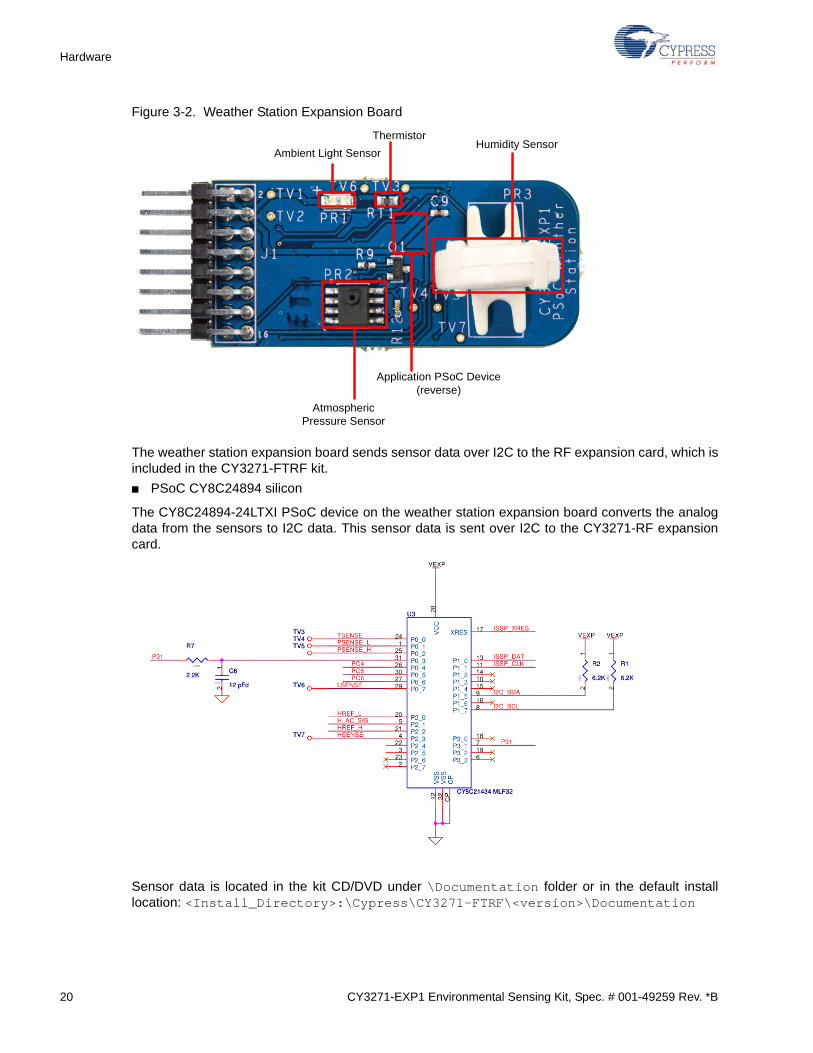
■ PSoC CY8C24894 silicon
The CY8C24894-24LTXI PSoC device on the weather station expansion board converts the analogdata from the sensors to I2C data. This sensor data is sent over I2C to the CY3271-RF expansioncard.
Sensor data is located in the kit CD/DVD under \Documentation folder or in the default installlocation: <Install_Directory>:\Cypress\CY3271-FTRF\<version>\Documentation
Ambient Light Sensor
ThermistorHumidity Sensor
Application PSoC Device (reverse)
Atmospheric Pressure Sensor

CY3271-EXP1 Environmental Sensing Kit, Spec. # 001-49259 Rev. *B 21
Hardware
3.2 Pigtail Thermistor Expansion Board
The pigtail thermistor expansion board features a thermistor on a three-foot cable. The thermistor atthe end of the cable is identical to the thermistor used on the RF expansion card allowing dual tem-perature readings. The pigtail thermistor expansion board does not have a PSoC on board; instead,it uses the PSoC from the RF expansion board to read the sensor. Resistors are chosen to removeoffset errors from the thermistor measurement; see AN2017 - PSoC 1 Thermistor-Based Thermom-eter.
Figure 3-3. Hardware Block Diagram for Pigtail Sensor Board
Figure 3-4. Pigtail Thermistor Expansion Board
Interface Connector
Pigtail Thermistor
Pigtail Thermistor

22 CY3271-EXP1 Environmental Sensing Kit, Spec. # 001-49259 Rev. *B
Hardware
Figure 3-5. Temperature Sensor Schematic
VTHERM_DIV
VTEMP_EXC VTEMP
VOUT_33
VOUT_33
VOUT_33
NO LOADNO LOAD
0603
R1
10K .1%
0603
R1
10K .1%
1 2
+AC14.7 uFd 16v
+AC14.7 uFd 16v
TV1TV1
TV3TV3TV4TV4
TV2TV2
J2
2 PIN HDR KEYED
J2
2 PIN HDR KEYED
11
22
0603
R2
390
0603
R2
390
1 2
0603
R3 390
0603
R3 390
1 2
0402
C2
0.1 uFd04
02
C2
0.1 uFd
1 2

CY3271-EXP1 Environmental Sensing Kit, Spec. # 001-49259 Rev. *B 23
4. Code Examples
4.1 My First Example Project
See the CY3271-FTRF kit user guide at http://www.cypress.com/go/CY3271-FTRF for a detailedexplanation of how to create a PSoC Designer project. All code examples are available on theCY3271-FTRF kit CD/DVD or at: <Install_Directory>:\Cypress\CY3271-FTRF\<ver-sion>\Firmware.
4.2 Weather Station Code Example
4.2.1 Project Objective
This example demonstrates how the weather station expansion board talks to the RF expansioncard. The weather station board has sensors for light, temperature, humidity, and pressure. The datafrom the weather station board is read by the RF_I2C_Bridge board (from CY3271-FTRF kit) throughan I2C protocol and transmitted to the PC hub (PC dongle from CY3271-FTRF kit) wirelessly usingthe CyFi SNP protocol.
The hardware has a capacitive humidity sensor to detect humidity. Because the CY8C24894 PSoCdevice has only two rows of analog blocks, the dynamic reconfiguration feature of PSoC Designer isused to read the data of all four sensors. See the PSoC Designer User Guide for more informationon dynamic reconfiguration.
This example uses the following user modules:
CY3271_EXP1_Weather_Station Configuration
■ ADCINC12: This user module converts the analog values from the sensors to digital value. The input to the user module is set to read the pressure sensor, light sensor, and temperature sensor one after the other in the firmware.
■ DAC: This user module stalls the microprocessor until the input voltage is stabilized before the ADC conversion can take place.
■ E2PROM: This user module stores the sensor data.
■ EzI2Cs: This user module configures PSoC on weather station board as I2C slave. The slave data is available for acquisition using a bridge board that is configured as I2C master.
■ PGA: Two instances of this user module is used to obtain a dual amplification of the analog input.
Humidity Configuration
■ CSD: This user module detects the capacitive changes due to changes in humidity.

24 CY3271-EXP1 Environmental Sensing Kit, Spec. # 001-49259 Rev. *B
Code Examples
4.2.2 Device Configuration

CY3271-EXP1 Environmental Sensing Kit, Spec. # 001-49259 Rev. *B 25
Code Examples
4.2.3 Flowchart
4.2.4 Verify Output
Operate the weather station demonstration by downloading the corresponding hex file to the RFexpansion card. Note that the weather station board is pre-programmed and does not need to beprogrammed.
1. Connect the RF expansion card to the PC bridge.
2. Insert the PC Bridge into any free USB port of your PC/laptop.
3. Open PSoC Programmer and load RF_I2C_BRIDGE.hex provided with CY3271-FTRF kit.
Note After installation, this file is available at <Install_Directory>:\Cypress\CY3271-FTRF\<version>\Firmware
4. Set Device Family to 27x43 and Device to CY8C27443. Click Program.
Start Components
Find Common
Mode Offset Gain
Initialize Sensor Scan
Measure Temperature
Measure Pressure
Measure Light (Lux)
Measure Humidity
Correct Pressure Reading
Is Temperature
Nominal?Yes
No
Report Results to
SCD
Dynamically Reconfigure
PSoC for CapSense
Dynamically Reconfigure
PSoC for Sensor Scan
Reset

26 CY3271-EXP1 Environmental Sensing Kit, Spec. # 001-49259 Rev. *B
Code Examples
Figure 4-1. PSoC Programmer Settings
5. Disconnect the RF expansion card from the PC bridge, leaving the bridge connected to your computer.
6. Attach the weather station expansion board and battery pack to the RF expansion card, as shown in Figure 4-2.
Figure 4-2. RF Expansion Card Connected to the Battery Pack and Weather Station Boards
7. Power the RF expansion card by sliding the ON/OFF switch on the battery pack towards the card.

CY3271-EXP1 Environmental Sensing Kit, Spec. # 001-49259 Rev. *B 27
Code Examples
Figure 4-3. Turning ON the Switch
8. Open the SCD software.
9. Place the PC bridge in Bind mode using SCD.
10.Click Manage to set up the sensor network.
Figure 4-4. Manage Network within SCD
11. In the Manage System Configuration screen, click Add to add a new node.
12.On the Node Binding screen, click Start Binding.
ON

28 CY3271-EXP1 Environmental Sensing Kit, Spec. # 001-49259 Rev. *B
Code Examples
Figure 4-5. Node Binding Window
13.After activating this function, you have approximately 10 to 30 seconds to press the bind button on the RF expansion card.
Figure 4-6. Press Bind Button
14.Verify the success of the bind. A successful bind window looks similar to Figure 4-7.

CY3271-EXP1 Environmental Sensing Kit, Spec. # 001-49259 Rev. *B 29
Code Examples
Figure 4-7. Successful Bind Window
15.Click Next to go to the Node Binding (2 of 2) window. In this window, assign a name to the newly bound node. On the Node Configuration pane, click Load Node configuration from a file and load Weather Station Dashboard Configuration.node.xml from the Device Template folder located on the CY3271-EXP1 kit CD/DVD.
Figure 4-8. Node Configuration

30 CY3271-EXP1 Environmental Sensing Kit, Spec. # 001-49259 Rev. *B
Code Examples
16.Select graphical or textual mode of data display. The data is displayed in graphical or text format on the SCD screen.
17.Click Apply on all successive dialog boxes until the main SCD window reappears.
Note that the weather station expansion board is not calibrated. If more accurate measurements arerequired, then the board must be calibrated. The calibration process is described in SensorCalibration chapter on page 35.
4.3 Pigtail Sensor Code Example
4.3.1 Project Objective
This project outputs the temperature values from two different sensors: the pigtail thermistor on thepigtail sensor board and the thermistor on the RF_I2C_Bridge board. The pigtail sensor board doesnot have a PSoC on board but the signal lines from the sensor are routed to the male header on theboard. The CY8C27443 device on the RF_I2C_Bridge reads both the sensor values and outputs tothe PC hub (PC dongle from CY3271-FTRF kit) wirelessly using the CyFi SNP protocol.
This project uses the following user modules:
■ CYFISNP: This module implements the entire star network wireless protocol and all protocol modes, in addition to low level radio communication and radio control by the MCU.
■ ADCINC: The incremental ADC is used to read the analog values from pigtail thermistor and on board thermistor one after the other in firmware.
■ PGA: This module facilitates the route ability of the analog inputs to the ADC analog block.
■ TX8: This module is used for serial communication with host and for debugging.
■ Timer8: This module implements an 8-bit timer that is clocked by a divider of SysClk. It is used to calibrate the sleep timer that is clocked by the 32 kHz system oscillator.

CY3271-EXP1 Environmental Sensing Kit, Spec. # 001-49259 Rev. *B 31
Code Examples
4.3.2 Device Configuration

32 CY3271-EXP1 Environmental Sensing Kit, Spec. # 001-49259 Rev. *B
Code Examples
4.3.3 Flowchart
4.3.4 Verify Output
The pigtail thermistor demonstration can be operated by downloading the corresponding hex file tothe RF expansion card.
1. Connect the RF expansion card to the PC bridge.
2. Insert the PC bridge into any free USB port of your computer.
3. Open PSoC Programmer and load RF_I2C_BRIDGE.hex provided with the CY3271-FTRF kit.
Note After installation, this file is available at <Install_Directory>:\Cypress\CY3271-FTRF\<version>\Firmware.
4. Set Device Family to 27x43 and Device to CY8C27443. Click Program.
5. Disconnect the RF expansion card from the PC bridge, leaving the bridge connected to your computer.
6. Attach the pigtail thermistor expansion board and battery pack to the RF expansion card.
7. Power the RF expansion card by sliding the ON/OFF switch on the battery pack towards the card.
8. Open the SCD software.
START
Bind button pressed?
Start bind process and assign Device ID to node
Yes
Wake button pressed?
Set flag to send data
Read temperature from pigtail
thermistor and on-board thermistor
Run CYFISNP protocol to send data
Start timer and CYFISNP; enable global interrupts
Received data from
hub?
Process data received
Yes
No
No

CY3271-EXP1 Environmental Sensing Kit, Spec. # 001-49259 Rev. *B 33
Code Examples
9. Place the PC bridge in Bind mode using SCD as follows:
a. Click the Manage button to set up the sensor network.
b. In the Manage Network screen, click Add to add a new node.
c. On the Node Binding screen, click on Begin Binding.
d. After this function is activated, the user has about 10 to 30 seconds to press the bind button on the RF expansion card.
e. Verify the success of the bind.
9. Click Next to go to the Node Binding (2 of 2) window. In this window, assign a name to the newly bound node. On the Node Configuration pane, click the Load Node configuration from a file option and load Pigtail_Thermistor_Dashboard_Configuration.xml from the Device Template folder located on the CY3271-EXP1 kit CD/DVD.
Note After installation, this file is available at <Install_Directory>:\Cypress\CY3271-EXP1\<version>\Firmware
10.Select graphical or textual mode of data display. The data is displayed in graphical or text format on the SCD screen.
11.Click Apply on all successive dialog boxes until the main SCD window reappears.
Note that the pigtail thermistor expansion card is not calibrated. If more accurate measurements arerequired, then the board must be calibrated. The calibration process is described in SensorCalibration chapter on page 35.

34 CY3271-EXP1 Environmental Sensing Kit, Spec. # 001-49259 Rev. *B
Code Examples

CY3271-EXP1 Environmental Sensing Kit, Spec. # 001-49259 Rev. *B 35
5. Sensor Calibration
5.1 Overview
The SCD allows you to calibrate a sensor in the system using linear calibration. Calibration canimprove measurement accuracy of sensors, such as the humidity sensor, whose accuracy is speci-fied at ±15% relative humidity. SCD sensor calibration is based on data pairs (raw value versusadjusted value). Calibration of the humidity sensor is also possible in firmware. Calibration in firm-ware is useful when the hardware is sent without access to the local calibration settings in SCD, orwhen the SCD is not the target software.
To register a calibration pair, select a graph and click the Calibrate button. Click the Add Point but-ton and enter the appropriate values. Raw Value is the value reported by the SCD and AdjustedValue is the data point value. There is no limit on the number of data pairs. More data pairs meanmore accurate calibration and more accurate measurements from the SCD.
For one data pair, SCD computes the offset calibration equation in the form of y = x + b using theprovided data.
Calibrated Value = Raw Value + Offset
For two or more data pairs, SCD computes the offset and gain calibration equation in the form of y =mx + b using a least squares best fit of the provided data:
Calibrated Value = (Slope) × (Raw Value) + Offset
This calibration equation is used to calibrate all incoming raw data from the sensor before displayingit in the SCD. The SCD also records both raw and calibrated data for each sensor in its data log.
To access the Calibrate Sensor window, highlight the sensor that you want to calibrate. Then, eitherclick on the Calibrate button on the toolbar, or go to Tools > Selected Sensor > Calibrate.

36 CY3271-EXP1 Environmental Sensing Kit, Spec. # 001-49259 Rev. *B
Sensor Calibration
Figure 5-1. Calibrate Sensor Window
5.1.1 Calibrating Humidity Sensor in Firmware
Calibration of the humidity sensor is also possible in firmware. The process is similar to the calibra-tion process in the SCD. Two types of calibration are possible in firmware: offset calibration and gaincalibration. Offset calibration is easier and corrects most errors in the sensor reading; gain calibra-tion can be used for high accuracy applications.
To calibrate the offset in firmware, you must know the relative humidity to a good degree of accuracy.Turn on and connect the kit; compare the readings it supplies with the actual relative humidity. Now,in the firmware package CY3271_EXP1_Weather_Station provided with the kit, open the main.c file.The conversion equation for the humidity measurement is in the ConvertHumidity function on line185. Use the difference between the known value and reported value to correct the offset value inthis equation. Next, compile and program the weather station board to complete the offset calibra-tion.
Gain calibration is more involved, requiring data taken at a minimum of two points and some math.Gain calibration is usually not required for this sensor unless you want high accuracy. During at leasttwo known accurate relative humidities, record the real relative humidity and the value reported bythe Weather Station. Plot these values versus the known humidity values and determine the linearrelationship between the two, with measured relative humidity as a function of real humidity. Use thisequation, in the form y = m (x + b), and substitute the equation in main.c, line 185 for x. Simplify theresulting equation and replace the equation in the firmware. Compile and program your board. Thiscompletes gain calibration.

CY3271-EXP1 Environmental Sensing Kit, Spec. # 001-49259 Rev. *B 37
Sensor Calibration
5.2 Alarms and Data Aggregation Intervals
The Chart Options dialog enables to set low and high alarms for a selected sensor. To view thiswindow, highlight the sensor for which you want to set an alarm. Then, either click on the Chart but-ton on the toolbar or go to Tools > Selected Sensor > Chart Options.
Figure 5-2. Chart Options for Setting Alarms

38 CY3271-EXP1 Environmental Sensing Kit, Spec. # 001-49259 Rev. *B
Sensor Calibration
If the application detects a triggered low or high alarm, it reports this event on the Alarms panel. Thealarm values are also reflected on the sensor display tile if graph option is selected.
Figure 5-3. Alarm History
Data aggregation intervals are also specified using the Chart Options dialog. To enable long orshort term aggregation, select the corresponding check box and specify the data sampling period.The long term aggregation interval must be longer than the short term aggregation interval.
5.3 Data Export
Selected sensor data, data reported by all sensors, and alarm history are exported to a file usingcomma separated values format. To do this, click File > Export Data..
5.4 Save Configuration
To save a network configuration, use File > Save Configuration or File > Save Configuration As.The network configuration is saved as an XML file.

CY3271-EXP1 Environmental Sensing Kit, Spec. # 001-49259 Rev. *B 39
A. Appendix
The schematic and board layouts are available on the CY3271-EXP1 kit CD/DVD. After installation,they are available at: <Install_Directory>:\Cypress\CY3271-EXP1\<version>\Hard-ware.
A.1 Schematics
A.1.1 Weather Station Board
NO
TE: T
his
Exp
ansi
on B
oard
Doe
s N
ot H
ave
An
Onb
oard
Vol
tage
Reg
ulat
or -
DO
NO
T P
ower
With
> 5
Vdc
Tem
pera
ture
Sen
sor A
mbi
ent L
ight
Det
ecto
r
0.10
0" 8
x2 M
ale
Pin
Hea
der
Pre
ssur
eS
enso
r
Hum
idity
Sen
sor
Hum
idity
Ref
eren
ceC
aps
R9, R10, R11 and Q1 can
be used to drive the
Pressure Sensor using
constant current
PCB:PDCR-9441
ISS
P_X
RE
SIS
SP
_CLK
ISS
P_D
AT
I2C
_SD
AI2
C_S
CL
ISS
P_C
LK
ISS
P_X
RE
S
ISS
P_D
AT
I2C
_SD
A
I2C
_SC
L
TS
EN
SE
PO
4
TS
EN
SE
PS
EN
SE
_H
PS
EN
SE
_L
HS
EN
SE
HS
EN
SE
PO
4
LSE
NS
E
LSE
NS
E
P31
P31
PO
6
PO
6HR
EF
_L
HR
EF
_HH
_AC
_SIG
H_A
C_S
IG
HR
EF
_LH
RE
F_H
PS
EN
SE
_L
PS
EN
SE
_H
SE
LR
DY
SE
LR
DY
VE
XP
VE
XP
VE
XP
VE
XP
VE
XP
VE
XP V
EX
P
VE
XP
VE
XP
VE
XP
Titl
e
Siz
eD
ocum
ent
Num
ber
Rev
CY
PR
ES
S S
EM
ICO
ND
UC
TOR
© 2
011
FIR
ST
TO
UC
H R
F W
EA
TH
ER
ST
AT
ION
BO
AR
DT
itle
Siz
eD
ocum
ent
Num
ber
Rev
CY
PR
ES
S S
EM
ICO
ND
UC
TOR
© 2
011
FIR
ST
TO
UC
H R
F W
EA
TH
ER
ST
AT
ION
BO
AR
DT
itle
Siz
eD
ocum
ent
Num
ber
Rev
CY
PR
ES
S S
EM
ICO
ND
UC
TOR
© 2
011
FIR
ST
TO
UC
H R
F W
EA
TH
ER
ST
AT
ION
BO
AR
D
+A
C2
4.7
uFd
16v
+A
C2
4.7
uFd
16v
U3
CY
8C24
894
QF
N56U
3
CY
8C24
894
QF
N56
P1_
118
P1_
317
P1_
516
P1_
715
P2_
041
P2_
12
P2_
242
P2_
31
P2_
443
P2_
556
P2_
644
P2_
755
XR
ES
36
P0_
045
P0_
154
P0_
246
P0_
353
P0_
447
GND250GND119
P3_
033
P3_
110
P3_
234
P3_
39
P3_
435
P3_
58
P3_
77
P4_
037
P4_
16
P4_
238
P4_
35
P4_
439
P4_
54
P4_
640
P4_
73
P5_
029
P5_
114
P5_
230
P5_
313
P0_
552
P0_
648
P0_
751
DP
20
VDD122
P1_
025
P1_
226
P1_
427
P1_
628
DM
21
VDD249
P5_
431
P5_
512
P5_
632
P5_
711
P7_
024
P7_
723
CP57
0603
R4
3.32
K 1
%
0603
R4
3.32
K 1
%
1 2
0805
C8
150
pFd
0805
C8
150
pFd
1 2
0603
C5
NO
LO
AD
0603
C5
NO
LO
AD
TV
7T
V7
0805
C3
NO
LO
AD
0805
C3
NO
LO
AD
1 2
0402
C1
0.1
uFd
0402
C1
0.1
uFd
0603
R3
4.99
K1%
0603
R3
4.99
K1%
1 2
J1
8X2
PIN
HD
R R
A
J1
8X2
PIN
HD
R R
A
VIN
1
GN
D3
ISS
P_X
RE
S5
ISS
P_C
LK7
ISS
P_D
AT
9
ISS
P_S
EL
11
TY
PE
4
FT
PC
0[6]
13
FT
PC
0[5]
15
SD
A6
SC
L8
nPA
SS
/BO
OS
T2
FT
PC
0[2]
16F
TP
C0[
3]14
FT
PC
0[4]
12V
BA
TT
10
0402
R10
NO
LO
AD
0402
R10
NO
LO
AD
TV
4T
V4
PR
2N
PP
-301
B-1
00A
PR
2N
PP
-301
B-1
00A
IN2-
5
Out
+2
IN1-
4
Out
-6
NC11NC23NC37IN
+8
0402
R7
2.2K
0402
R7
2.2K
TV
2T
V2
0402
R9
NO
LO
AD
0402
R9
NO
LO
AD
TV
6T
V6
0402
C9
0.1
uFd
0402
C9
0.1
uFd
TV
5T
V5
0603
R1
6.2K
0603
R1
6.2K
1 2
0603
R11
NO
LO
AD
0603
R11
NO
LO
AD
1 2
+P
R1
LX19
72A
+P
R1
LX19
72A
1 2
0402
R12
NO
LO
AD
0402
R12
NO
LO
AD
+P
R3
2381
691
900
01+
PR
323
81 6
91 9
0001
1 20603
R2
6.2K
0603
R2
6.2K
1 2
0805
C6
10nF
d0805
C6
10nF
d
1 2
0603
25°
RT
13.
3K
0603
25°
RT
13.
3K
1 2
0402
R13
ZE
RO
0402
R13
ZE
RO
0402
R6
NO
LO
AD
0402
R6
NO
LO
AD
Q1
NO
LO
AD
Q1
NO
LO
AD
1
2 3T
V1
TV
1
0805
C7
100
pFd
0805
C7
100
pFd
1 2T
V3
TV
3

40 CY3271-EXP1 Environmental Sensing Kit, Spec. # 001-49259 Rev. *B
A.1.2 Thermistor Board
VTEMPVTEMP_EXCVTHERM_DIV
VTHERM_DIV
VTEMP_EXC VTEMP
VOUT_33
VOUT_33
VOUT_33
VOUT_33
NOTE: This Expansion Board Does Not Have An OnboardVoltage Regulator - DO NOT Power With > 5Vdc
TemperatureSensor
0.100" 8x2 MalePin Header
NO LOADNO LOAD
0603
R1
10K .1%
0603
R1
10K .1%
1 2
+AC14.7 uFd 16v
+AC14.7 uFd 16v
TV1TV1
TV3TV3TV4TV4
J1
8X2 PIN HDR RA
J1
8X2 PIN HDR RA
V331
GND3
ISSP_XRES5
ISSP_CLK7
ISSP_DAT9
ISSP_SEL11
TYPE 4
FTPC0[6]13
FTPC0[5]15
SDA-SHDN 6
SCL-CTRL 8
nPASS/BOOST 2
FTPC0[2] 16FTPC0[3] 14FTPC0[4] 12
VBATT 10
TV2TV2
J2
2 PIN HDR KEYED
J2
2 PIN HDR KEYED
11
22
0603
R2
390
0603
R2
390
1 2
0603
R3 390
0603
R3 390
1 2
0402
C2
0.1 uFd
0402
C2
0.1 uFd
1 2

CY3271-EXP1 Environmental Sensing Kit, Spec. # 001-49259 Rev. *B 41
A.2 Weather Station Board Layout
A.2.1 Top Layer
A.2.2 Bottom Layer
A.2.3 Primary Silkscreen
A.2.4 Secondary Silkscreen

42 CY3271-EXP1 Environmental Sensing Kit, Spec. # 001-49259 Rev. *B
A.3 Thermistor Board Layout
A.3.1 Top Layer
A.3.2 Bottom Layer
A.3.3 Primary Silkscreen
A.3.4 Secondary Silkscreen

CY3271-EXP1 Environmental Sensing Kit, Spec. # 001-49259 Rev. *B 43
A.4 Bill of Materials
A.4.1 CY3271-EXP1 Weather Station BOM
Item Qty. Reference Description Manufacturer Mfg. Part Number
1 2 C1,C9 CAP .1UF 16V CERAMIC Y5V 0402 Panasonic - ECG ECJ-0EF1C104Z
1 1 C2 CAP 4.7UF 16V Tantalum 3216 Nichicon F931C475MAA
2 1 C5 CAP CERAMIC 47PF 50V 0603 SMD Panasonic - ECG ECJ-1VC1H470J
3 1 C6 CAP CER 10000PF 25V C0G 0805 KemetC0805C103F3GACTU
4 1 C7 CAP CERAMIC 100PF 100V NP0 0805 Panasonic - ECG ECJ-2VC2A101J
5 1 C8 CAP CERAMIC 150PF 100V NP0 0805 Panasonic - ECG ECJ-2VC2A151J
6 1 J1 CONN HEADER 16POS .100" R/A TIN Molex/Waldom Electronics Corp 90122-0128
7 1 PR1 IC AMBIENT LIGHT DETECTOR 1206 Microsemi-IPG LX1972IBC-TR
8 1 PR3 IC SENSOR CAPACITIVE HUMIDITYVishay/BC Components
2381 691 90001
9 1 RT1 THERMISTOR NTC 3.3K OHM 5% 0603 Panasonic - ECG ERT-J1VT332J
10 2 R1,R2 RES 6.2K OHM 1/10W 5% 0603 SMD Panasonic - ECG ERJ-3GEYJ622V
11 1 R3 RES 4.99K OHM 1/16W 1% 0603 SMD Panasonic - ECG ERJ-3EKF4991V
12 1 R4RES CHIP 3.32K OHM 1/16W 1% 0603 SMD
Panasonic-ECG ERJ-3EKF3321V
13 1 R7 RES 2.2K OHM 1/16W 5% 0402 SMD Panasonic - ECG ERJ-2GEJ222X
14 1 R13 RES ZERO OHM 1/16W 0402 SMD Panasonic - ECG ERJ-2GE0R00X
15 1 U3 PSoC Mixed-Signal ArrayCypress Semiconductor
CY8C24894-24LFXI
NO LOAD Components
17 1 C3 CAP NO LOAD 0805 NA NA
18 1 Q1TRANSISTOR PNP Low VCEsat SOT-23 NO LOAD
NXP Semiconductors PBSS5350T
19 4R6,R9,R10,R12
RES NO LOAD 0402 SMD NA NA
20 1 R11 RES NO LOAD 0603 SMD NA NA
21 7TV1,TV2,TV3,TV4,TV5,TV6, TV7
TEST VIA 40 HOLE 20 PLATED None
Special Installation Components
16 1 PR2 IC SENS PRES 15PSIA SO8 SMD GE Sensing NPP-301B-100A

44 CY3271-EXP1 Environmental Sensing Kit, Spec. # 001-49259 Rev. *B
A.4.2 CY3271-EXP1 Thermistor BOM
Item Qty. Reference Part Manufacturer Mfg. Part Number
1 1 PCB Rev 01 Cypress PDCR-9438
2 1 C1 CAP 4.7UF 16V Tantalum 3216 Nichicon F931C475MAA
3 1 J1 CONN HEADER 16POS .100" R/A TINMolex/Waldom Electronics Corp
90122-0128
4 1 J2 CONN HEADER 2POS .100 R/A TINMolex/Waldom Electronics Corp
22-05-3021
5 1 R1 RES CHIP 10.0K OHM 1/16W .1% 0603 SMD Panasonic - ECG ERA-3AEB103V
6 1 R2 RES 390 OHM 1/16W 1% 0603 SMD Panasonic - ECG ERJ-3EKF3900V
7 4 TV1,TV2,TV3,TV4 TEST VIA 40 HOLE 20 PLATED None None
No Load Components
8 1 C2 CAP 0402 NO LOAD
9 1 R3 RES 0603 NO LOAD