Embed Size (px)
Citation preview
JX Nippon Exploration andProduction (U.K.) Limited
UtgardEnvironmental Statement Utgard Unit P.312 (UKCS), PL046E (NCS) and PL046F (NCS)
FM160131
AU-UTG-00013 Page 2 of 52
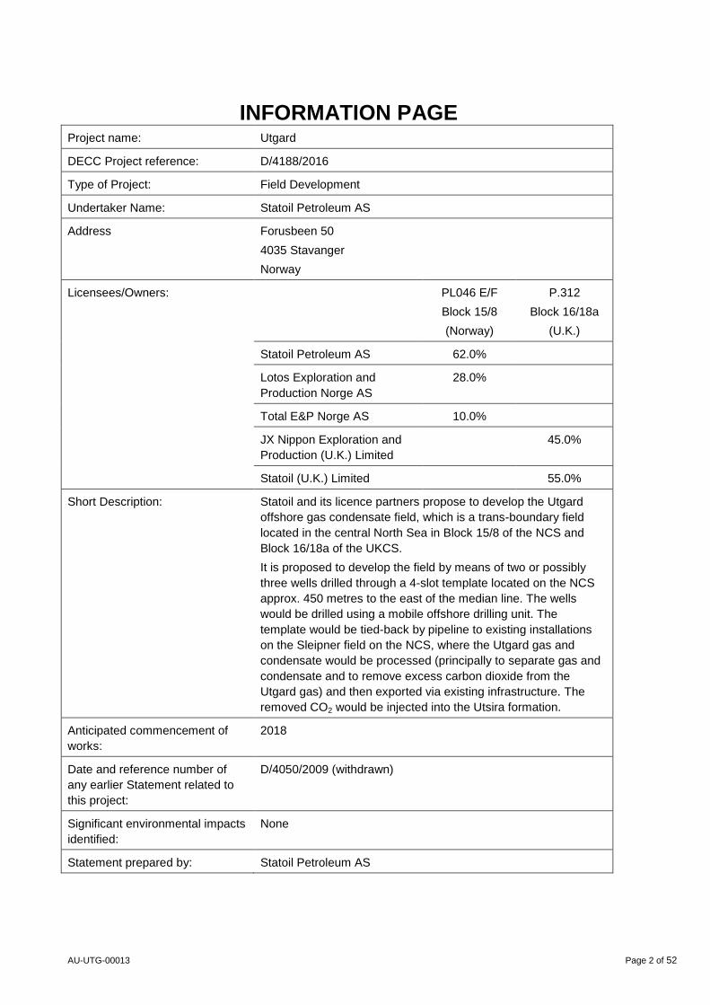
INFORMATION PAGE Project name: Utgard
DECC Project reference: D/4188/2016
Type of Project: Field Development
Undertaker Name: Statoil Petroleum AS
Address Forusbeen 50
4035 Stavanger
Norway
Licensees/Owners: PL046 E/F
Block 15/8
(Norway)
P.312
Block 16/18a
(U.K.)
Statoil Petroleum AS 62.0%
Lotos Exploration and
Production Norge AS
28.0%
Total E&P Norge AS 10.0%
JX Nippon Exploration and
Production (U.K.) Limited
45.0%
Statoil (U.K.) Limited 55.0%
Short Description: Statoil and its licence partners propose to develop the Utgard
offshore gas condensate field, which is a trans-boundary field
located in the central North Sea in Block 15/8 of the NCS and
Block 16/18a of the UKCS.
It is proposed to develop the field by means of two or possibly
three wells drilled through a 4-slot template located on the NCS
approx. 450 metres to the east of the median line. The wells
would be drilled using a mobile offshore drilling unit. The
template would be tied-back by pipeline to existing installations
on the Sleipner field on the NCS, where the Utgard gas and
condensate would be processed (principally to separate gas and
condensate and to remove excess carbon dioxide from the
Utgard gas) and then exported via existing infrastructure. The
removed CO2 would be injected into the Utsira formation.
Anticipated commencement of
works:
2018
Date and reference number of
any earlier Statement related to
this project:
D/4050/2009 (withdrawn)
Significant environmental impacts
identified:
None
Statement prepared by: Statoil Petroleum AS
AU-UTG-00013 Page 3 of 52
Table of contents 1 Non-Technical Summary .............................................................................................. 5
1.1 Introduction ..................................................................................................................... 5
1.2 Operations Summary ...................................................................................................... 5
1.3 Environmental Management ............................................................................................ 6
1.4 Environmental Sensitivities .............................................................................................. 6
1.5 Evaluation of Potential Environmental Impacts ................................................................ 8
1.6 Assessment of Potential Significant Environmental Impacts ............................................ 8
1.7 Mitigation Measures ........................................................................................................ 8
1.8 Conclusion ...................................................................................................................... 8
2 Introduction ................................................................................................................... 9
3 Project Description ....................................................................................................... 10
3.1 Location .......................................................................................................................... 10
3.2 Conditions on the host platform ....................................................................................... 11
3.3 Existing development and infrastructure in the Sleipner Area .......................................... 11
3.4 Ownership and Operatorship ........................................................................................... 13
3.5 Resources and Development Solutions ........................................................................... 13
3.5.1 General ........................................................................................................................... 13
3.5.2 Template Location ........................................................................................................... 15
3.5.3 Drilling ............................................................................................................................. 15
3.5.4 Sub Sea Production System ............................................................................................ 16
3.5.5 Flow Assurance ............................................................................................................... 17
3.5.6 Pipeline ........................................................................................................................... 17
3.5.7 Topside ........................................................................................................................... 18
3.6 Schedule ......................................................................................................................... 18
4 Reserves and Production ............................................................................................. 18
4.1 Reserves ......................................................................................................................... 18
4.2 Production ....................................................................................................................... 18
4.3 Production Change at Sleipner ........................................................................................ 19
4.4 Produced Water .............................................................................................................. 20
5 Measures to Minimize Environmental Impacts ........................................................... 20
5.1 Chemicals ....................................................................................................................... 20
5.2 Drill Cuttings and Oily Drainage Water ............................................................................ 21
5.3 Subsea Infrastructure ...................................................................................................... 21
5.4 Pipeline pre-commissioning/commissioning .................................................................... 21
6 Environmental Aspects in the Influenced Area ........................................................... 21
6.1 Environmental Conditions and Natural Resources .......................................................... 23
6.1.1 Physical Conditions ......................................................................................................... 23
6.1.2 Human Influence ............................................................................................................. 25
6.1.3 Plankton .......................................................................................................................... 25
6.1.4 Benthic Communities ...................................................................................................... 26
6.1.5 Fish ................................................................................................................................. 26
AU-UTG-00013 Page 4 of 52
6.1.6 Seabirds .......................................................................................................................... 29
6.2 Marine Mammals ............................................................................................................. 31
6.3 Protected and particularly valuable and vulnerable areas ................................................ 32
6.4 Fishing Areas .................................................................................................................. 33
6.5 Shipping .......................................................................................................................... 37
6.6 Cultural Heritage and Relicts of the Past ......................................................................... 37
6.7 Environmental sensitivities .............................................................................................. 38
7 Potential Environmental Impacts ................................................................................. 39
7.1 Emissions to Air .............................................................................................................. 39
7.1.1 Emissions to Air from Utgard at the host facilities ............................................................ 40
7.2 CO2 injection ................................................................................................................... 42
7.3 Discharges to Sea ........................................................................................................... 43
7.3.1 Discharges to Sea from Utgard at the host facilities ........................................................ 43
7.4 Waste Handling ............................................................................................................... 44
7.5 Physical Impacts and Presence of Subsea Infrastructure ................................................ 44
7.6 Accidental Emissions and Discharges ............................................................................. 45
8 Assessment of Environmental Impacts ....................................................................... 48
8.1 Norwegian Continental Shelf (NCS) ................................................................................ 48
8.1.1 Emissions to Air .............................................................................................................. 48
8.1.2 Discharges to Sea ........................................................................................................... 48
8.1.3 Physical Impacts ............................................................................................................. 49
8.2 United Kingdom Continental Shelf (UKCS) ...................................................................... 49
8.2.1 Emissions to Air .............................................................................................................. 50
8.2.2 Discharges to Sea ........................................................................................................... 50
8.2.3 Physical Impacts ............................................................................................................. 50
9 Conclusions ................................................................................................................... 51
10 References ..................................................................................................................... 52
AU-UTG-00013 Page 5 of 52
1 Non-Technical Summary
1.1 Introduction
The Utgard field is a trans-boundary gas and condensate field with a portion of the total reserves located on the UK
side of the border. The field is located in Blocks 15/8 (NCS) and 16/18a (UKCS) in the central North Sea, about 21
km west of the Sleipner complex. Utgard will be developed from a four slot subsea template with 2 wells, and a 21
km pipeline connecting the wells to the Sleipner T platform (SLT). All processing will take place at SLT, and all the
infrastructures will be placed on the Norwegian side of the border. Although one of the two well targets is on the
UKCS, this target will be reached from the drilling location on NCS.
The gas in the Utgard field has a CO2 content of about 16%. To reduce this to a level suitable for blending with the
Sleipner export stream, the gas will be routed through the existing CO2-removal facilities at SLT (CO2 reduction to
3-5%). Separated CO2 will be injected into the Utsira formation for permanent disposal. Remaining CO2 will be
blended in the SLT export gas stream.
The Sleipner area includes the gas and condensate fields Sleipner East and Sleipner West with the satellite fields
Gungne, Loke, Alfa Nord and the 3rd
party tie-in fields Sigyn, Gudrun and Gina Krog. Condensate from Sleipner is
transported through pipeline for treatment at Kårstø in South West Norway. The gas is mixed with gas from the
Kollsnes and Nyhamna terminals at the Sleipner riser platform and transported to the European market in the
Gassled pipeline system.
The environmental and social impacts from oil- and gas activities in the Sleipner area, including Utgard, are already
described in the Regional Impact Assessment (RIA) of the North Sea from 2006 and in the Integrated Management
Plan for the North Sea and Skagerrak (Management Plan) from 2013. An application has been submitted to The
Norwegian Ministry of Petroleum and Energy asking the Ministry’s acknowledgement that the Norwegian legal
requirements for impact assessment are already fulfilled by the existing RIA-North Sea and the Integrated
Management Plan, and that a new field specific impact assessment is not required.
Statoil as the operator of the Utgard field has prepared this Environmental Statement. The Environmental
Statement (ES) presents the findings of the assessment of environmental consequences of construction and
operation of the Utgard field.
The submission of this ES is required under the Offshore Petroleum Production and Pipelines (Assessment of
Environmental Effects) Regulations 1999 as amended by the Offshore Petroleum Production and Pipelines
(Assessment of Environmental Effects) (Amendment) Regulations 2007 because the UK share of the production
exceeds the threshold set in the regulations, which is 500 tonnes or more per day of oil or 500,000 cubic metres or
more per day of gas.
Notwithstanding the regulatory requirements, internal impact assessments are routinely carried out by Statoil for all
offshore development activities as a matter of Company policy.
1.2 Operations Summary
The production on Sleipner is now below plateau and yearly production is declining. Utgard will use production
capacity that has become available at the Sleipner facilities. Production of the Utgard resources will cause no
significant change to emissions and discharges at Sleipner compared with those currently allowed under the
regulatory permits that are in place for the Sleipner field operations, or compared to the emission forecasts that
AU-UTG-00013 Page 6 of 52
were considered within the Regional Environmental Impact Assessment (RIA) of the North Sea (2006) and the
Management Plan of the North Sea and Skagerrak (2013).
Start-up of Utgard is scheduled in December 2019 with peak production in the years 2020-22. The production
period at the Utgard field is estimated to be approximately 12 years.
1.3 Environmental Management
Statoil has established an environmental policy which supports the goals of zero harm to the environment and
sustainable development. Statoil’s environmental policy has been adopted by the Company’s top management and
applies to all the Company’s activities and to all employees.
The commitments that follow from the environmental policy are realised through Statoil’s implementation of
mechanisms and systems for efficient execution, measurement, control and improvement of all the activities and
processes carried out by the Company and its suppliers.
This Environmental Statement identifies mitigating measures and possible improvements that will be assessed in
the further planning work for Utgard. These measures will be followed up continuously by the project during the
development and production phases.
1.4 Environmental Sensitivities
All infrastructures, activities, emissions to air and discharges to sea associated with the development and operation
of Utgard will take place on the Norwegian continental shelf in the North Sea.
The proposed development is located in an area that is typical of the offshore regions of the central North Sea
where hydrographical, meteorological, geological and biological characteristics are relatively uniform over large
areas. Users of the area are mainly those associated with oil and gas exploration and development, shipping and
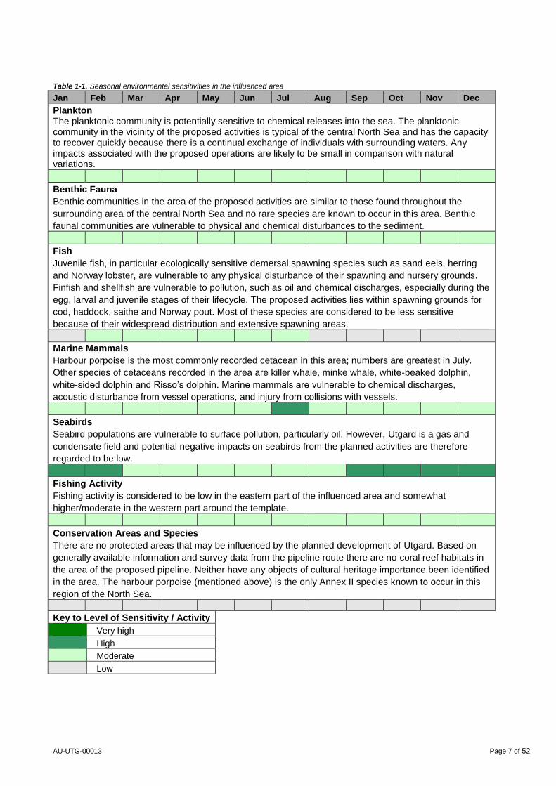
fishing. Table 1-1 provides a summary of the key features of the offshore environment in this area, and their
seasonal patterns of activity or sensitivity, based on descriptions and referenced information sources in Section 6.
AU-UTG-00013 Page 7 of 52
Table 1-1. Seasonal environmental sensitivities in the influenced area
Jan Feb Mar Apr May Jun Jul Aug Sep Oct Nov Dec
Plankton The planktonic community is potentially sensitive to chemical releases into the sea. The planktonic community in the vicinity of the proposed activities is typical of the central North Sea and has the capacity to recover quickly because there is a continual exchange of individuals with surrounding waters. Any impacts associated with the proposed operations are likely to be small in comparison with natural variations.
Benthic Fauna
Benthic communities in the area of the proposed activities are similar to those found throughout the
surrounding area of the central North Sea and no rare species are known to occur in this area. Benthic
faunal communities are vulnerable to physical and chemical disturbances to the sediment.
Fish
Juvenile fish, in particular ecologically sensitive demersal spawning species such as sand eels, herring
and Norway lobster, are vulnerable to any physical disturbance of their spawning and nursery grounds.
Finfish and shellfish are vulnerable to pollution, such as oil and chemical discharges, especially during the
egg, larval and juvenile stages of their lifecycle. The proposed activities lies within spawning grounds for
cod, haddock, saithe and Norway pout. Most of these species are considered to be less sensitive
because of their widespread distribution and extensive spawning areas.
Marine Mammals
Harbour porpoise is the most commonly recorded cetacean in this area; numbers are greatest in July.
Other species of cetaceans recorded in the area are killer whale, minke whale, white-beaked dolphin,
white-sided dolphin and Risso’s dolphin. Marine mammals are vulnerable to chemical discharges,
acoustic disturbance from vessel operations, and injury from collisions with vessels.
Seabirds
Seabird populations are vulnerable to surface pollution, particularly oil. However, Utgard is a gas and
condensate field and potential negative impacts on seabirds from the planned activities are therefore
regarded to be low.
Fishing Activity
Fishing activity is considered to be low in the eastern part of the influenced area and somewhat
higher/moderate in the western part around the template.
Conservation Areas and Species
There are no protected areas that may be influenced by the planned development of Utgard. Based on
generally available information and survey data from the pipeline route there are no coral reef habitats in
the area of the proposed pipeline. Neither have any objects of cultural heritage importance been identified
in the area. The harbour porpoise (mentioned above) is the only Annex II species known to occur in this
region of the North Sea.
Key to Level of Sensitivity / Activity
Very high
High
Moderate
Low
AU-UTG-00013 Page 8 of 52
1.5 Evaluation of Potential Environmental Impacts
Offshore developments have the potential to affect the environment in different ways. This may include physical
disturbance of the seabed, and the creation of gaseous emissions, aqueous discharges and solid wastes. An
evaluation of the relative significance of these potential environmental effects for the activities proposed in
connection with the development of Utgard has been undertaken so that any potentially significant impacts can be
assessed and mitigated. The evaluation takes account of the activity causing the impact or risk associated with the
main project activities and the sensitivity of the location. Consideration was also given to the routine, non-routine
and potential accidental/emergency events.
Particular emphasis has been placed on the matters raised in the Supplementary Guidance issued by the
Department of Energy and Climate Change (DECC) following the Macondo well incident in the Gulf of Mexico
(Deepwater Horizon).
1.6 Assessment of Potential Significant Environmental Impacts
This assessment concludes that the development of Utgard will have only minor to negligible environmental
impacts within the Norwegian continental shelf and negligible to no impact on the UK continental shelf.
1.7 Mitigation Measures
The activities associated with the Utgard development will be conducted in accordance with Statoil’s environmental
policy. A summary of the main commitments for the Utgard field development are as follows:
Energy optimisation to reduce fuel consumption and associated emissions to air.
Environmentally harmful chemicals (black or red categories, ref. Section 5.1) will not be used. Chemical
selection shall be based on best available techniques (BAT) principles.
Cuttings from drilling with oil based mud will not be released to sea, but transported to shore for handling.
The drilling programme will comply with Statoil’s Emergency Procedures and Oil Spill Contingency Plan.
All subsea infrastructures will be made over-trawlable.
All activities will be carried out in line with Statoil’s HSE policy and current Norwegian legislation.
Utgard will use available capacity in the existing topside process facilities on SLT. No new power production
equipment will be needed. Total environmental emissions from the Sleipner field facilities will not increase as a
result of the Utgard tie-in, but will decrease at a slower pace than might otherwise be the case. Existing
environmental standards and mitigating measures will apply also for the Utgard part of the production.
1.8 Conclusion
All facilities related to the Utgard development are to be installed on the Norwegian Continental Shelf (NCS). There
are no planned activities on the UK Continental Shelf (UKCS).
In overall terms, the proposed activities at the Utgard field and at the Sleipner complex are not expected to cause
any significant adverse environmental impacts. The Utgard field and the Sleipner complex are located in an area
which is typical of the central North Sea in terms of habitats and marine life. None of the environmental receptors is
assessed as being particularly sensitive to the type of activities proposed.
AU-UTG-00013 Page 9 of 52
The activities associated with the Utgard development will be included in the Company’s environmental
measurement and monitoring programmes, which track performance against corporate targets for important
categories of emissions and discharges.
This assessment demonstrates that the planned drilling of the two Utgard wells, the marine installation work, and
the processing of the Utgard reserves at the Sleipner complex will have no significant effects on environmental
resources in the central North Sea. It is concluded that the Utgard field development and operation can be
implemented without significant adverse effects on the environment.
Statoil believes that the mitigating measures that will be taken represent an appropriate balance between
protecting the environment and securing the economic benefits of the planned production.
2 Introduction
Utgard is a cross-boundary gas and condensate field covered by licences PL046E and PL046F in the NCS (Block
15/8) and P.312 in the UKCS (Block 16/18a).
Statoil Petroleum AS is the operator of the Norwegian licence, with licence partners Lotos and Total. JX Nippon
Exploration and Production (U.K.) Limited is the operator of the UK licence, with licence partner Statoil (U.K.)
Limited. The Statoil Petroleum AS is leading the development activities, and has prepared this Environmental
Statement.
Utgard is planned to be developed with a four slot subsea template, 21 km of pipeline and tie-in to the Sleipner T
platform. Two wells will be drilled, with one target each side of the UK/Norway border. All installations and
infrastructure will be located on the Norwegian side of the median line - the UK well being directionally drilled from
the template location on the NCS. The distance from the template to the border line will be approximately 450 m.
Utgard will use existing available process capacity at the Sleipner facilities.
The CO2 content of the Utgard well stream is high (ca. 16%). Since the Gassled system requirement is 2.5 mol%
CO2, the gas will be routed through the existing CO2-removal facilities at SLT. Separated CO2 will be injected into
the Utsira formation for permanent disposal.
On the Norwegian continental shelf the necessary environmental impact assessments for Utgard have already
been completed by inclusion in regional assessments covering the Sleipner area. These regional assessments are:
Integrated Management of the Marine Environment of the North Sea and Skagerrak (Management Plan),
2013
Regional Impact Assessment (RIA) of the North Sea from 2006
The production (Norwegian part), emissions and discharges from the development of the Utgard are specifically
included in both these regional assessments.
Based on a case-specific application from the operator, the Ministry of Petroleum and Energy (MPE) may grant
approval that Norwegian legal requirements for Environmental Impact Assessment are fulfilled by existing impact
assessments as listed above. Statoil has submitted such an application to the Ministry.
This Environmental Statement (ES) presents an assessment of the environmental consequences of the
construction of the Utgard subsea infrastructure and the production of the Utgard reserves at the Sleipner
installations.
AU-UTG-00013 Page 10 of 52
The submission of this ES is required under the Offshore Petroleum Production and Pipelines (Assessment of
Environmental Effects) Regulations 1999 as amended by the Offshore Petroleum Production and Pipelines
(Assessment of Environmental Effects) (Amendment) Regulations 2007 because the UK share of the production
exceeds the threshold set in the regulations, which is 500 tonnes or more per day of oil or 500,000 cubic metres or
more per day of gas.
3 Project Description
3.1 Location
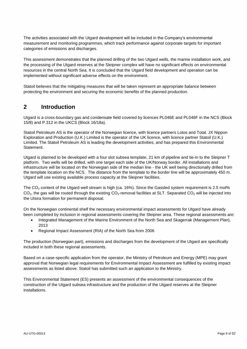
Utgard is a cross-boundary gas and condensate field which is located in block 15/8 on the Norwegian Continental
Shelf (NCS) and in block 16/18a on the UK Continental Shelf. Relevant licences are PL046E and PL046F on the
NCS and P.312 on the UKCS. The field is located about 21 km west of the Sleipner field centre (Sleipner A
platform) (Figure 3-1).
Water depth in the Utgard area is 110-120 m.
Figure 3-1. Location of the Utgard field in relation to the Sleipner field centre
AU-UTG-00013 Page 11 of 52
3.2 Conditions on the host platform
Sleipner production has declined from plateau rates, and as a result the processing capacity at the Sleipner T
platform is now sufficient to receive the production from Utgard.
3.3 Existing development and infrastructure in the Sleipner Area
The Sleipner area includes the gas and condensate fields Sleipner East and Sleipner West with the satellite fields
Gungne, Loke, Alfa Nord and the 3rd
party tie-in fields Sigyn, Gudrun and Gina Krog. Condensate from Sleipner is
transported through pipeline for treatment at Kårstø in South West Norway. The gas is mixed with gas from the
Kollsnes and Nyhamna terminals at the Sleipner riser platform and transported to the European market in the
Gassled pipeline system.
Sleipner East
The Sleipner East Field has been developed using an integrated process, drilling and living quarter platform
(Sleipner A, SLA). In addition a riser platform has been installed, (Sleipner R, which ties the SLA to pipelines for
gas transport), and a flare tower (Sleipner F). Two subsea templates have also been installed, one for the
production of the northern part of Sleipner East and one for the production of the Loke deposit. In addition, three
wells from Sigyn are tied to SLA.
Production on Sleipner East started in August 1993.
Sleipner West
Sleipner West is connected to Sleipner East, and both fields are operated by the same operation organization.
Sleipner West has been developed using a wellhead platform (Sleipner B) that is remotely controlled from the
Sleipner A platform on the Sleipner East field, and a process facility (Sleipner T) that is connected with Sleipner A
by walkway.
Untreated well stream from Sleipner West is transported in a 12 kilometre long pipeline to the Sleipner T platform.
Gas and condensate from Sleipner West is processed on Sleipner T. CO2 is separated from the gas in two 20
meter high towers on the Sleipner T platform. In the towers the CO2 from the gas is absorbed into liquid amine and
then separated from the amine in a recycle plant. From here, both gas and CO2 is led to Sleipner A. Processed gas
from Sleipner West goes to further export. Separated CO2 is injected in the Utsira formation via a separate injection
well. Unstable condensate from Sleipner West and Sleipner East is mixed at Sleipner A, and is then transported to
Kårstø for the production of stable condensate and NGL products.
Production on Sleipner West started in August 1996.
The Alfa Nord segment was developed in 2004 with a template connected to the Sleipner T through an 18
kilometre long pipeline.
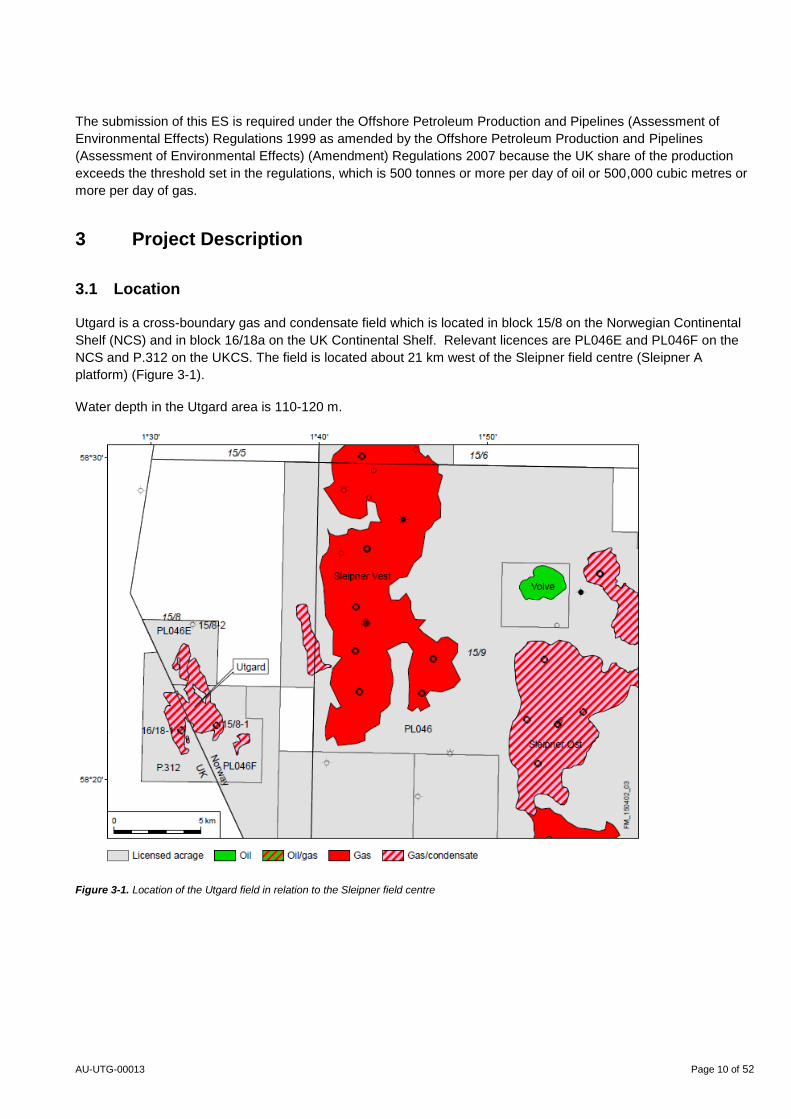
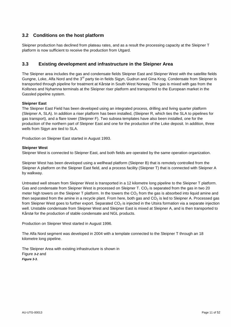
The Sleipner Area with existing infrastructure is shown in
Figure 3-2 and
Figure 3-3.
AU-UTG-00013 Page 12 of 52
Figure 3-2. The Sleipner fields with existing infrastructure
Figure 3-3. Photo showing the Sleipner A platform in front left with Sleipner T platform in the back
AU-UTG-00013 Page 13 of 52
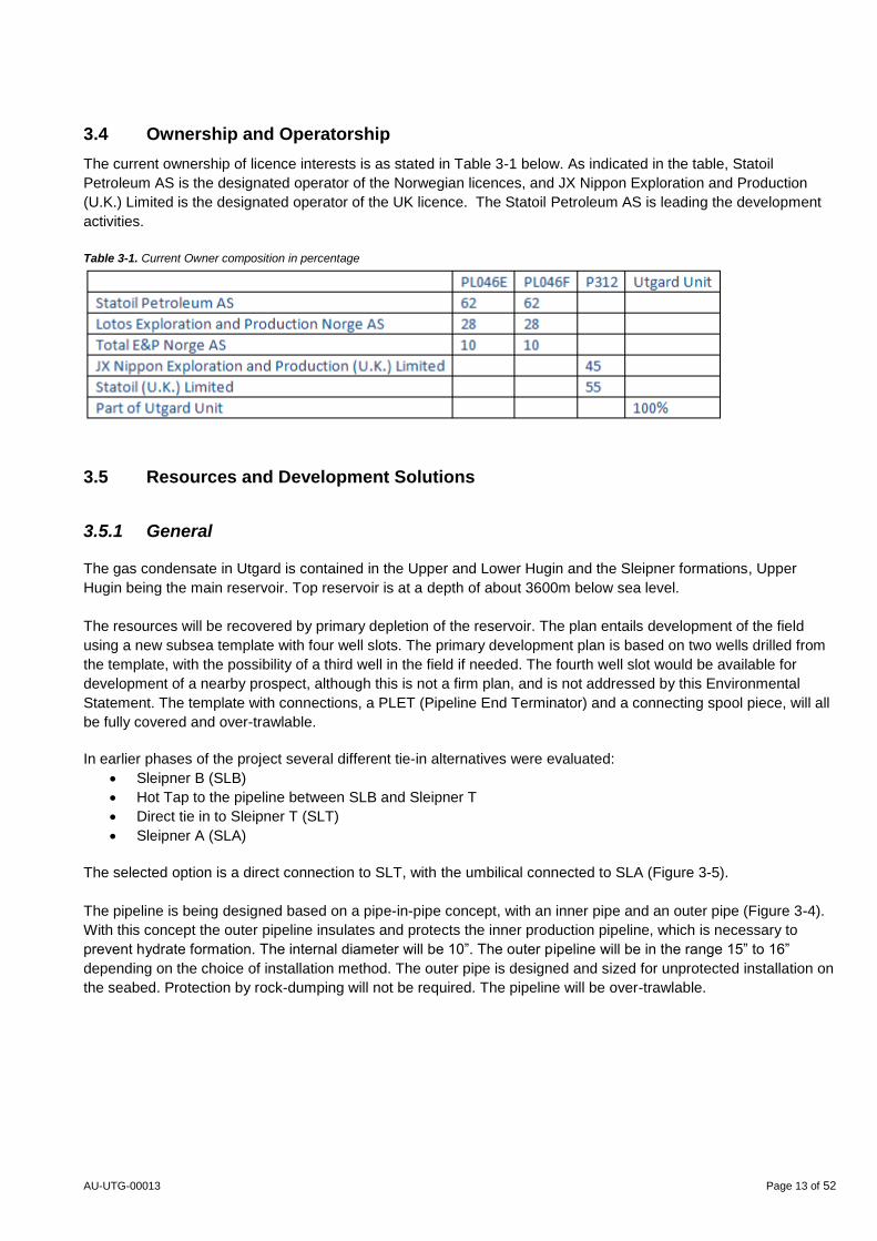
3.4 Ownership and Operatorship
The current ownership of licence interests is as stated in Table 3-1 below. As indicated in the table, Statoil
Petroleum AS is the designated operator of the Norwegian licences, and JX Nippon Exploration and Production
(U.K.) Limited is the designated operator of the UK licence. The Statoil Petroleum AS is leading the development
activities.
Table 3-1. Current Owner composition in percentage
3.5 Resources and Development Solutions
3.5.1 General
The gas condensate in Utgard is contained in the Upper and Lower Hugin and the Sleipner formations, Upper
Hugin being the main reservoir. Top reservoir is at a depth of about 3600m below sea level.
The resources will be recovered by primary depletion of the reservoir. The plan entails development of the field
using a new subsea template with four well slots. The primary development plan is based on two wells drilled from
the template, with the possibility of a third well in the field if needed. The fourth well slot would be available for
development of a nearby prospect, although this is not a firm plan, and is not addressed by this Environmental
Statement. The template with connections, a PLET (Pipeline End Terminator) and a connecting spool piece, will all
be fully covered and over-trawlable.
In earlier phases of the project several different tie-in alternatives were evaluated:
Sleipner B (SLB)
Hot Tap to the pipeline between SLB and Sleipner T
Direct tie in to Sleipner T (SLT)
Sleipner A (SLA)
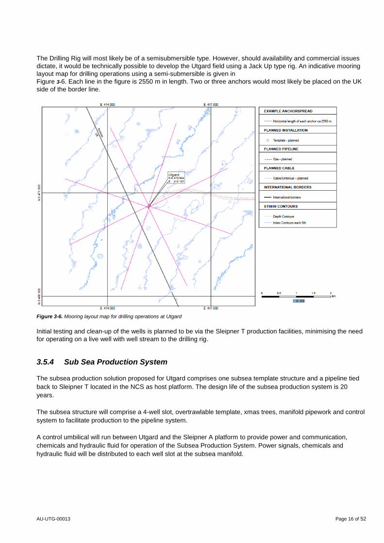
The selected option is a direct connection to SLT, with the umbilical connected to SLA (Figure 3-5).
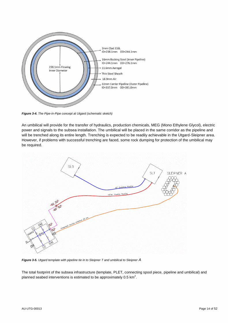
The pipeline is being designed based on a pipe-in-pipe concept, with an inner pipe and an outer pipe (Figure 3-4).
With this concept the outer pipeline insulates and protects the inner production pipeline, which is necessary to
prevent hydrate formation. The internal diameter will be 10”. The outer pipeline will be in the range 15” to 16”
depending on the choice of installation method. The outer pipe is designed and sized for unprotected installation on
the seabed. Protection by rock-dumping will not be required. The pipeline will be over-trawlable.
AU-UTG-00013 Page 14 of 52
Figure 3-4. The Pipe-in-Pipe concept at Utgard (schematic sketch)
An umbilical will provide for the transfer of hydraulics, production chemicals, MEG (Mono Ethylene Glycol), electric
power and signals to the subsea installation. The umbilical will be placed in the same corridor as the pipeline and
will be trenched along its entire length. Trenching is expected to be readily achievable in the Utgard-Sleipner area.
However, if problems with successful trenching are faced, some rock dumping for protection of the umbilical may
be required.
Figure 3-5. Utgard template with pipeline tie in to Sleipner T and umbilical to Sleipner A
The total footprint of the subsea infrastructure (template, PLET, connecting spool piece, pipeline and umbilical) and
planned seabed interventions is estimated to be approximately 0.5 km2.

AU-UTG-00013 Page 15 of 52
3.5.2 Template Location
The planned template location is at a mid-point between the two proposed gas producer down-hole targets. This
location is given in Table 3-2. The final location will be defined following a site survey.
Table 3-2. Planned location of template
Projection: ED_1950_UTM_Zone_31N
Geographic Lat: 58° 22’ 05,1” N 01° 33’ 01,2” E
Projected N: 6 470 604 m E: 415 197 m
3.5.3 Drilling
Two wells are planned from a central template location, ref.Table 3-2, both with similar inclination but with opposite
azimuths. Gas producer GP1 has a well length of 4338 m (4300 m TVD (Total Vertical Depth)) with its final depth
located in the UKCS. Gas producer GP3 has a well length of 4310 m (4272 m TVD) and has its final depth located
in the NCS.
The wells will be deviated below the conductor at a rate of 1 to 2 degrees per 30 metres until an angle of 15 degrees is reached. Thereafter, the wells will be drilled straight to their final depths (Total Depth; TD).
The following hole sizes and casings are planned in the wells:
42” hole 30” casing set approx. 200 m TVDSS
26” hole 20” casing set below Utsira Fm. ~1200 m TVDSS
17 ½” hole 13 3/8” casing set below Heimal Fm. ~2800 m TVDSS
12 ¼” hole 9 5/8” casing set below Cromer Knoll group/ Top of reservoir ~3600 m TVDSS
8 ½” hole (lower completion yet to be decided) to base Sleipner Fm. ~4300 m TVDSS
(Note: TVDSS = Total Vertical Depth below Sea Surface, Fm=formation)
Drilling fluids will be selected according to Statoil governing documentation. Most likely water based drilling fluids
will be used for well sections from the sea floor down to 1200 m (42”, 26” and 17½” sections) and oil based drilling
fluids thereafter (12 ¼” and 8 ½” sections). Cuttings from drilling with oil based mud will not be released to sea.
These oily cuttings will be shipped to shore for proper handling, treatment and disposal.
Discharges to sea from drilling of the upper well sections with water based mud (WBM) are shown in Table 3-3.
The discharges will happen at, or in the immediate vicinity of the Utgard template.
Table 3-3. Discharges to sea from drilling with water based mud systems (WBM)
AU-UTG-00013 Page 16 of 52
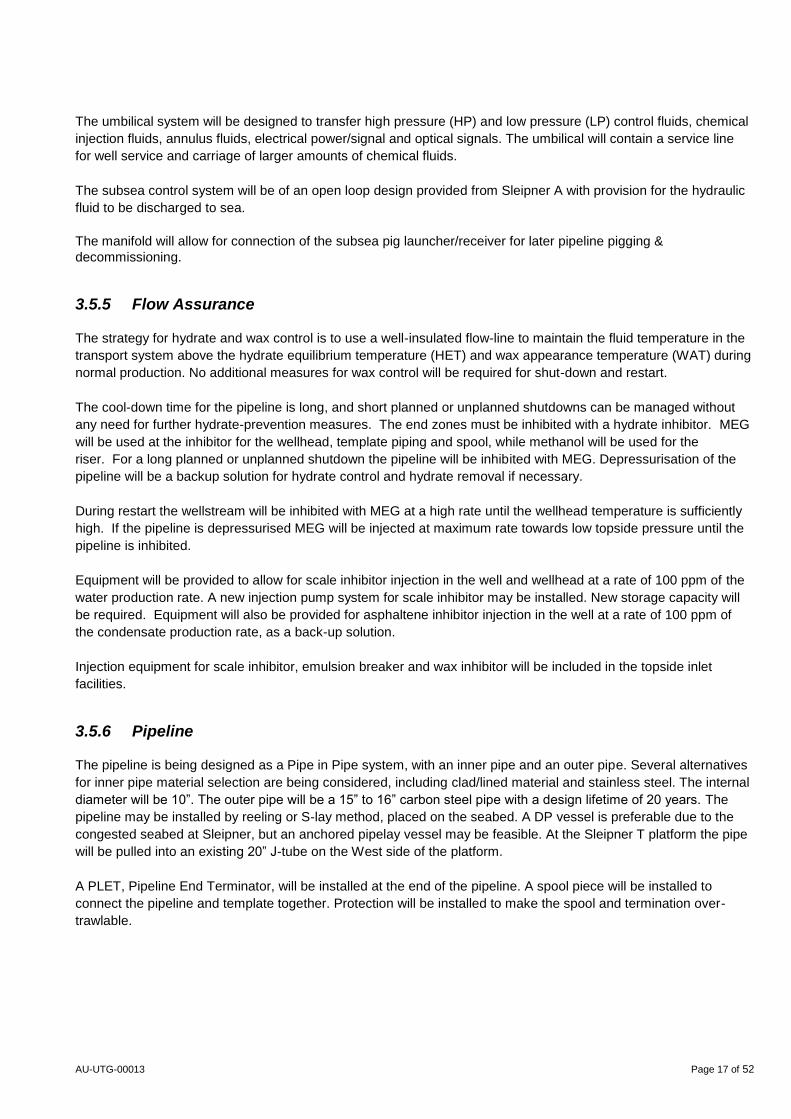
The Drilling Rig will most likely be of a semisubmersible type. However, should availability and commercial issues
dictate, it would be technically possible to develop the Utgard field using a Jack Up type rig. An indicative mooring
layout map for drilling operations using a semi-submersible is given in
Figure 3-6. Each line in the figure is 2550 m in length. Two or three anchors would most likely be placed on the UK
side of the border line.
Figure 3-6. Mooring layout map for drilling operations at Utgard
Initial testing and clean-up of the wells is planned to be via the Sleipner T production facilities, minimising the need
for operating on a live well with well stream to the drilling rig.
3.5.4 Sub Sea Production System
The subsea production solution proposed for Utgard comprises one subsea template structure and a pipeline tied
back to Sleipner T located in the NCS as host platform. The design life of the subsea production system is 20
years.
The subsea structure will comprise a 4-well slot, overtrawlable template, xmas trees, manifold pipework and control
system to facilitate production to the pipeline system.
A control umbilical will run between Utgard and the Sleipner A platform to provide power and communication,
chemicals and hydraulic fluid for operation of the Subsea Production System. Power signals, chemicals and
hydraulic fluid will be distributed to each well slot at the subsea manifold.
AU-UTG-00013 Page 17 of 52
The umbilical system will be designed to transfer high pressure (HP) and low pressure (LP) control fluids, chemical
injection fluids, annulus fluids, electrical power/signal and optical signals. The umbilical will contain a service line
for well service and carriage of larger amounts of chemical fluids.
The subsea control system will be of an open loop design provided from Sleipner A with provision for the hydraulic
fluid to be discharged to sea.
The manifold will allow for connection of the subsea pig launcher/receiver for later pipeline pigging &
decommissioning.
3.5.5 Flow Assurance
The strategy for hydrate and wax control is to use a well-insulated flow-line to maintain the fluid temperature in the
transport system above the hydrate equilibrium temperature (HET) and wax appearance temperature (WAT) during
normal production. No additional measures for wax control will be required for shut-down and restart.
The cool-down time for the pipeline is long, and short planned or unplanned shutdowns can be managed without
any need for further hydrate-prevention measures. The end zones must be inhibited with a hydrate inhibitor. MEG
will be used at the inhibitor for the wellhead, template piping and spool, while methanol will be used for the
riser. For a long planned or unplanned shutdown the pipeline will be inhibited with MEG. Depressurisation of the
pipeline will be a backup solution for hydrate control and hydrate removal if necessary.
During restart the wellstream will be inhibited with MEG at a high rate until the wellhead temperature is sufficiently
high. If the pipeline is depressurised MEG will be injected at maximum rate towards low topside pressure until the
pipeline is inhibited.
Equipment will be provided to allow for scale inhibitor injection in the well and wellhead at a rate of 100 ppm of the
water production rate. A new injection pump system for scale inhibitor may be installed. New storage capacity will
be required. Equipment will also be provided for asphaltene inhibitor injection in the well at a rate of 100 ppm of
the condensate production rate, as a back-up solution.
Injection equipment for scale inhibitor, emulsion breaker and wax inhibitor will be included in the topside inlet
facilities.
3.5.6 Pipeline
The pipeline is being designed as a Pipe in Pipe system, with an inner pipe and an outer pipe. Several alternatives
for inner pipe material selection are being considered, including clad/lined material and stainless steel. The internal
diameter will be 10”. The outer pipe will be a 15” to 16” carbon steel pipe with a design lifetime of 20 years. The
pipeline may be installed by reeling or S-lay method, placed on the seabed. A DP vessel is preferable due to the
congested seabed at Sleipner, but an anchored pipelay vessel may be feasible. At the Sleipner T platform the pipe
will be pulled into an existing 20” J-tube on the West side of the platform.
A PLET, Pipeline End Terminator, will be installed at the end of the pipeline. A spool piece will be installed to
connect the pipeline and template together. Protection will be installed to make the spool and termination over-
trawlable.
AU-UTG-00013 Page 18 of 52
3.5.7 Topside
The main principle for the Utgard tie-in to Sleipner is to use the existing processing and utility facilities so far as
possible. All process and utility systems will be reviewed and any need for modifications identified. A new riser will
be pulled in and emergency valves and flow meter will be installed. The flow will be routed to the existing inlet
separator and the gas further routed to the existing CO2-removal facilities. The gas will then be exported to the
Gassled system, and the condensate will be exported to Kårstø, Norway.
3.6 Schedule
The internal decision-making process for the Utgard is as follows:
DG1 (feasibility): 29.07.2013
DG2 (Concept selection) 01.08.2015
DG3 (Sanction): 01.07.2016
Submission of PDO/FDP: 01.07.2016
Abbreviations
DG: Decision Gate
PDO: Plan for Development and Operations (to Norwegian authorities)
FDP: Field Development Plan (to UK authorities)
The planned schedule for development activities is as follows:
Start modifications at Sleipner Second quarter 2017
Installation of template: Second quarter 2018
Drilling (two wells): Third quarter 2018
Installation of manifold: Second quarter 2019
Laying of pipeline and umbilical: Second quarter 2019
Start-up production: Fourth quarter 2019
4 Reserves and Production
4.1 Reserves
The Utgard reservoir contains gas condensate. The presented estimates of recoverable reserves are considered
as the maximum case. Establishing the expected (mean) case is ongoing.
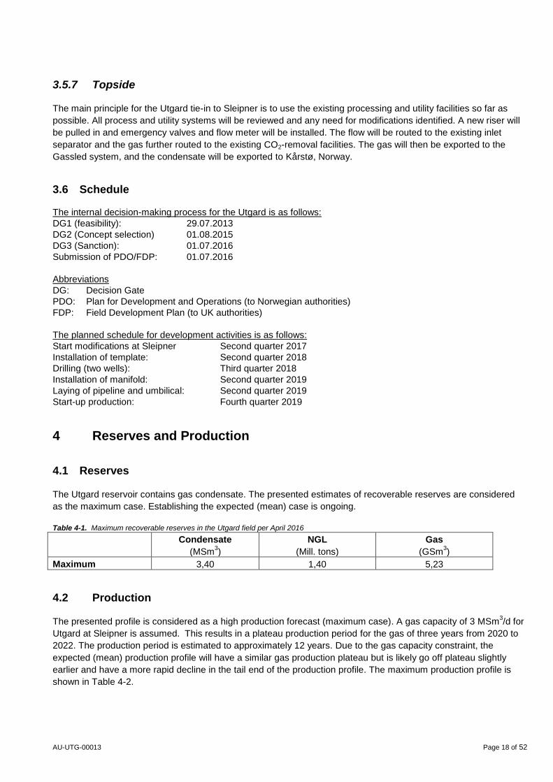
Table 4-1. Maximum recoverable reserves in the Utgard field per April 2016
Condensate
(MSm3)
NGL
(Mill. tons)
Gas
(GSm3)
Maximum 3,40 1,40 5,23
4.2 Production
The presented profile is considered as a high production forecast (maximum case). A gas capacity of 3 MSm3/d for
Utgard at Sleipner is assumed. This results in a plateau production period for the gas of three years from 2020 to
2022. The production period is estimated to approximately 12 years. Due to the gas capacity constraint, the
expected (mean) production profile will have a similar gas production plateau but is likely go off plateau slightly
earlier and have a more rapid decline in the tail end of the production profile. The maximum production profile is
shown in Table 4-2.
AU-UTG-00013 Page 19 of 52
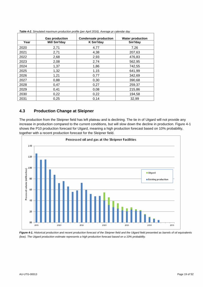
Table 4-2. Simulated maximum production profile (per April 2016). Average pr calendar day
Gas production
Condensate production
Water production
Year Mill Sm³/day K Sm³/day Sm³/day
2020 2,71 4,77 7,26
2021 2,71 4,38 207,63
2022 2,68 2,93 476,83
2023 2,08 2,74 562,95
2024 1,37 1,86 742,55
2025 1,32 1,15 641,99
2026 1,21 0,77 342,69
2027 0,88 0,30 390,68
2028 0,47 0,27 259,37
2029 0,41 0,08 215,86
2030 0,22 0,22 194,58
2031 0,25 0,14 32,99
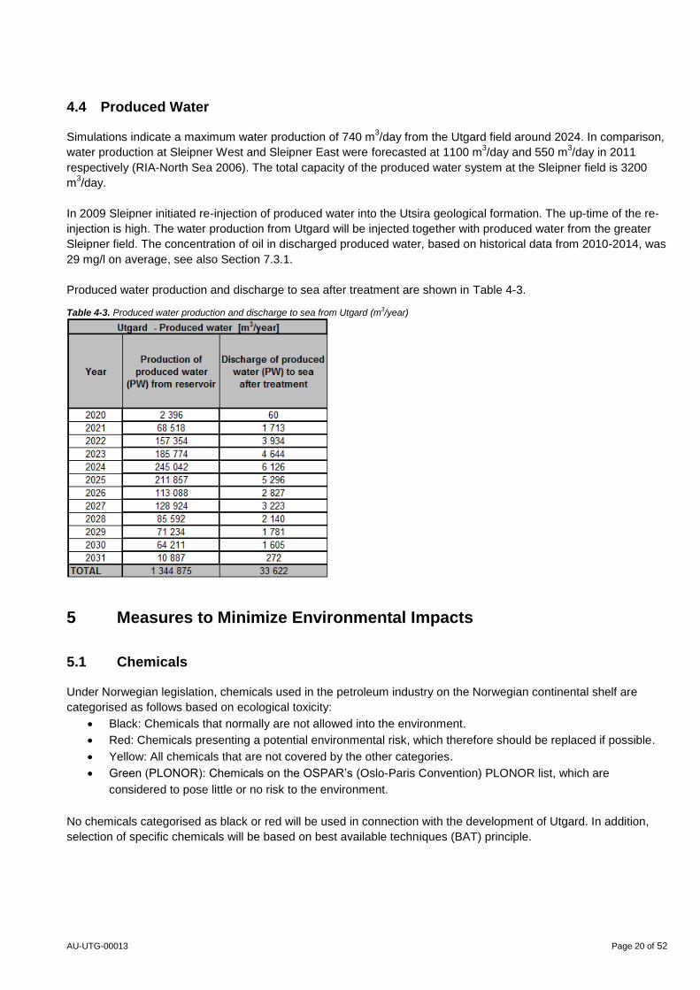
4.3 Production Change at Sleipner
The production from the Sleipner field has left plateau and is declining. The tie in of Utgard will not provide any
increase in production compared to the current conditions, but will slow down the decline in production. Figure 4-1
shows the P10 production forecast for Utgard, meaning a high production forecast based on 10% probability,
together with a recent production forecast for the Sleipner field.
Figure 4-1. Historical production and recent production forecast of the Sleipner field and the Utgard field presented as barrels of oil equivalents
(boe). The Utgard production estimate represents a high production forecast based on a 10% probability.
AU-UTG-00013 Page 20 of 52
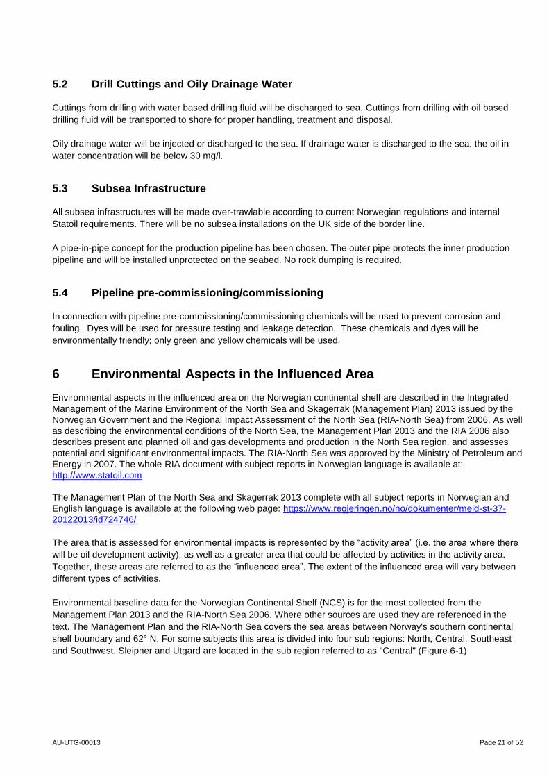
4.4 Produced Water
Simulations indicate a maximum water production of 740 m3/day from the Utgard field around 2024. In comparison,
water production at Sleipner West and Sleipner East were forecasted at 1100 m3/day and 550 m
3/day in 2011
respectively (RIA-North Sea 2006). The total capacity of the produced water system at the Sleipner field is 3200
m3/day.
In 2009 Sleipner initiated re-injection of produced water into the Utsira geological formation. The up-time of the re-
injection is high. The water production from Utgard will be injected together with produced water from the greater
Sleipner field. The concentration of oil in discharged produced water, based on historical data from 2010-2014, was
29 mg/l on average, see also Section 7.3.1.
Produced water production and discharge to sea after treatment are shown in Table 4-3. Table 4-3. Produced water production and discharge to sea from Utgard (m
3/year)
5 Measures to Minimize Environmental Impacts
5.1 Chemicals
Under Norwegian legislation, chemicals used in the petroleum industry on the Norwegian continental shelf are
categorised as follows based on ecological toxicity:
Black: Chemicals that normally are not allowed into the environment.
Red: Chemicals presenting a potential environmental risk, which therefore should be replaced if possible.
Yellow: All chemicals that are not covered by the other categories.
Green (PLONOR): Chemicals on the OSPAR’s (Oslo-Paris Convention) PLONOR list, which are
considered to pose little or no risk to the environment.
No chemicals categorised as black or red will be used in connection with the development of Utgard. In addition,
selection of specific chemicals will be based on best available techniques (BAT) principle.
AU-UTG-00013 Page 21 of 52
5.2 Drill Cuttings and Oily Drainage Water
Cuttings from drilling with water based drilling fluid will be discharged to sea. Cuttings from drilling with oil based
drilling fluid will be transported to shore for proper handling, treatment and disposal.
Oily drainage water will be injected or discharged to the sea. If drainage water is discharged to the sea, the oil in
water concentration will be below 30 mg/l.
5.3 Subsea Infrastructure
All subsea infrastructures will be made over-trawlable according to current Norwegian regulations and internal
Statoil requirements. There will be no subsea installations on the UK side of the border line.
A pipe-in-pipe concept for the production pipeline has been chosen. The outer pipe protects the inner production
pipeline and will be installed unprotected on the seabed. No rock dumping is required.
5.4 Pipeline pre-commissioning/commissioning
In connection with pipeline pre-commissioning/commissioning chemicals will be used to prevent corrosion and
fouling. Dyes will be used for pressure testing and leakage detection. These chemicals and dyes will be
environmentally friendly; only green and yellow chemicals will be used.
6 Environmental Aspects in the Influenced Area
Environmental aspects in the influenced area on the Norwegian continental shelf are described in the Integrated
Management of the Marine Environment of the North Sea and Skagerrak (Management Plan) 2013 issued by the
Norwegian Government and the Regional Impact Assessment of the North Sea (RIA-North Sea) from 2006. As well
as describing the environmental conditions of the North Sea, the Management Plan 2013 and the RIA 2006 also
describes present and planned oil and gas developments and production in the North Sea region, and assesses
potential and significant environmental impacts. The RIA-North Sea was approved by the Ministry of Petroleum and
Energy in 2007. The whole RIA document with subject reports in Norwegian language is available at:
http://www.statoil.com
The Management Plan of the North Sea and Skagerrak 2013 complete with all subject reports in Norwegian and
English language is available at the following web page: https://www.regjeringen.no/no/dokumenter/meld-st-37-
20122013/id724746/
The area that is assessed for environmental impacts is represented by the “activity area” (i.e. the area where there
will be oil development activity), as well as a greater area that could be affected by activities in the activity area.
Together, these areas are referred to as the “influenced area”. The extent of the influenced area will vary between
different types of activities.
Environmental baseline data for the Norwegian Continental Shelf (NCS) is for the most collected from the
Management Plan 2013 and the RIA-North Sea 2006. Where other sources are used they are referenced in the
text. The Management Plan and the RIA-North Sea covers the sea areas between Norway's southern continental
shelf boundary and 62° N. For some subjects this area is divided into four sub regions: North, Central, Southeast
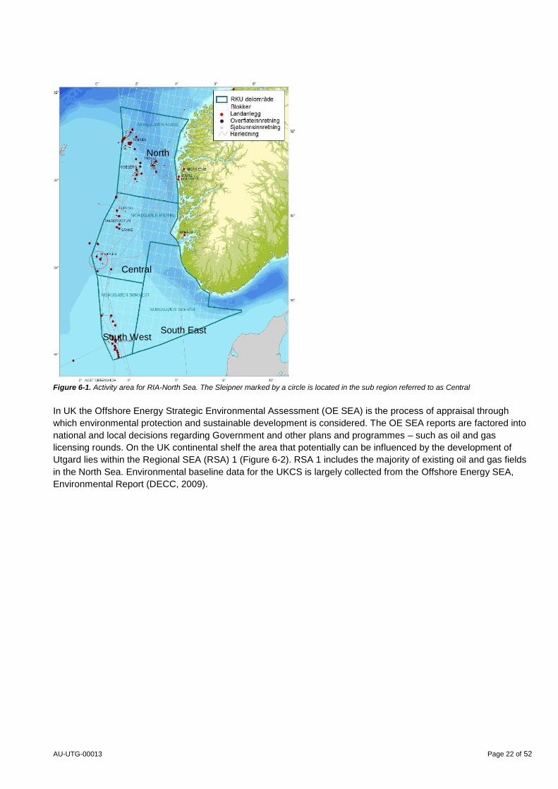
and Southwest. Sleipner and Utgard are located in the sub region referred to as "Central" (Figure 6-1).
AU-UTG-00013 Page 22 of 52
Figure 6-1. Activity area for RIA-North Sea. The Sleipner marked by a circle is located in the sub region referred to as Central
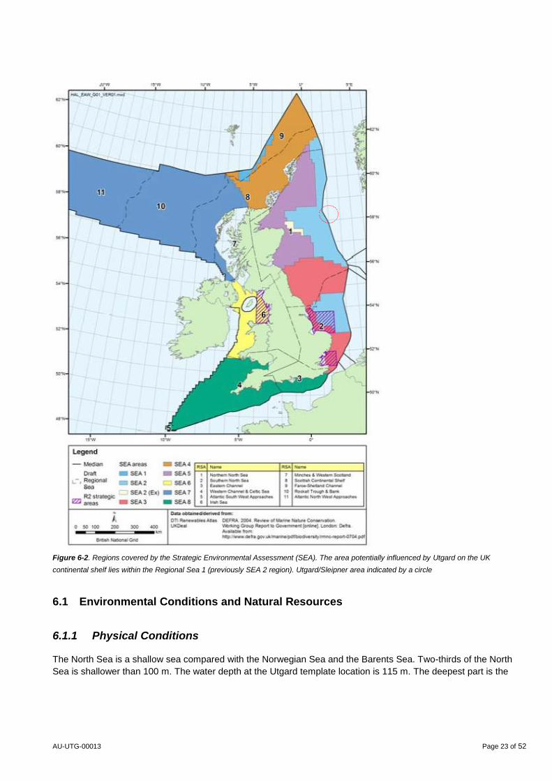
In UK the Offshore Energy Strategic Environmental Assessment (OE SEA) is the process of appraisal through
which environmental protection and sustainable development is considered. The OE SEA reports are factored into
national and local decisions regarding Government and other plans and programmes – such as oil and gas
licensing rounds. On the UK continental shelf the area that potentially can be influenced by the development of
Utgard lies within the Regional SEA (RSA) 1 (Figure 6-2). RSA 1 includes the majority of existing oil and gas fields
in the North Sea. Environmental baseline data for the UKCS is largely collected from the Offshore Energy SEA,
Environmental Report (DECC, 2009).
South East South West
Central
North
AU-UTG-00013 Page 23 of 52
Figure 6-2. Regions covered by the Strategic Environmental Assessment (SEA). The area potentially influenced by Utgard on the UK
continental shelf lies within the Regional Sea 1 (previously SEA 2 region). Utgard/Sleipner area indicated by a circle
6.1 Environmental Conditions and Natural Resources
6.1.1 Physical Conditions
The North Sea is a shallow sea compared with the Norwegian Sea and the Barents Sea. Two-thirds of the North
Sea is shallower than 100 m. The water depth at the Utgard template location is 115 m. The deepest part is the
AU-UTG-00013 Page 24 of 52
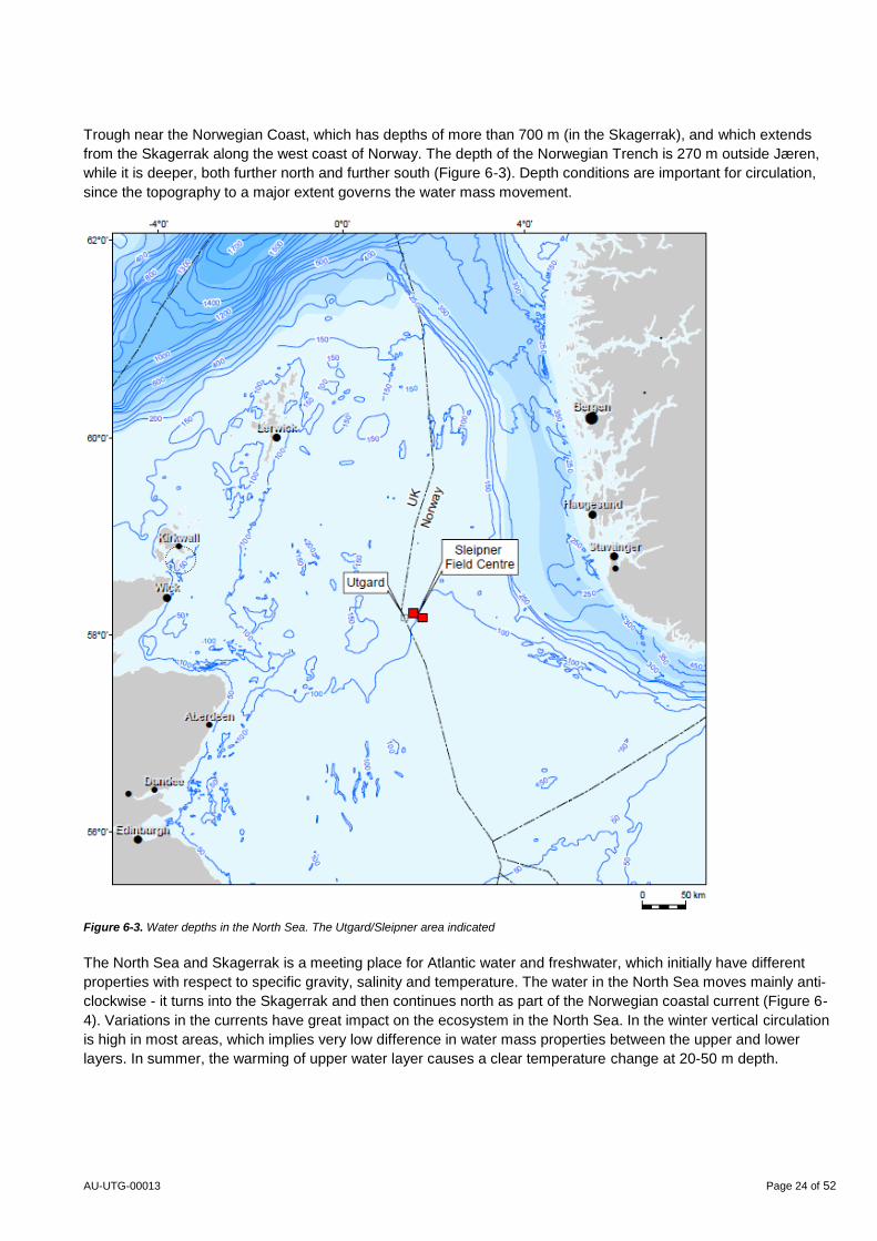
Trough near the Norwegian Coast, which has depths of more than 700 m (in the Skagerrak), and which extends
from the Skagerrak along the west coast of Norway. The depth of the Norwegian Trench is 270 m outside Jæren,
while it is deeper, both further north and further south (Figure 6-3). Depth conditions are important for circulation,
since the topography to a major extent governs the water mass movement.
Figure 6-3. Water depths in the North Sea. The Utgard/Sleipner area indicated
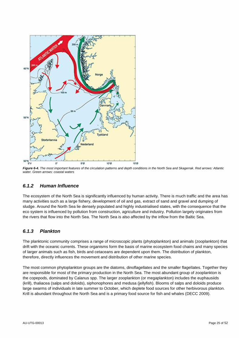
The North Sea and Skagerrak is a meeting place for Atlantic water and freshwater, which initially have different
properties with respect to specific gravity, salinity and temperature. The water in the North Sea moves mainly anti-
clockwise - it turns into the Skagerrak and then continues north as part of the Norwegian coastal current (Figure 6-
4). Variations in the currents have great impact on the ecosystem in the North Sea. In the winter vertical circulation
is high in most areas, which implies very low difference in water mass properties between the upper and lower
layers. In summer, the warming of upper water layer causes a clear temperature change at 20-50 m depth.
AU-UTG-00013 Page 25 of 52
Figure 6-4. The most important features of the circulation patterns and depth conditions in the North Sea and Skagerrak. Red arrows: Atlantic water. Green arrows: coastal waters
6.1.2 Human Influence
The ecosystem of the North Sea is significantly influenced by human activity. There is much traffic and the area has
many activities such as a large fishery, development of oil and gas, extract of sand and gravel and dumping of
sludge. Around the North Sea lie densely populated and highly industrialised states, with the consequence that the
eco system is influenced by pollution from construction, agriculture and industry. Pollution largely originates from
the rivers that flow into the North Sea. The North Sea is also affected by the inflow from the Baltic Sea.
6.1.3 Plankton
The planktonic community comprises a range of microscopic plants (phytoplankton) and animals (zooplankton) that
drift with the oceanic currents. These organisms form the basis of marine ecosystem food chains and many species
of larger animals such as fish, birds and cetaceans are dependent upon them. The distribution of plankton,
therefore, directly influences the movement and distribution of other marine species.
The most common phytoplankton groups are the diatoms, dinoflagellates and the smaller flagellates. Together they
are responsible for most of the primary production in the North Sea. The most abundant group of zooplankton is
the copepods, dominated by Calanus spp. The larger zooplankton (or megaplankton) includes the euphausiids
(krill), thaliacea (salps and doloids), siphonophores and medusa (jellyfish). Blooms of salps and doloids produce
large swarms of individuals in late summer to October, which deplete food sources for other herbivorous plankton.
Krill is abundant throughout the North Sea and is a primary food source for fish and whales (DECC 2009).
AU-UTG-00013 Page 26 of 52
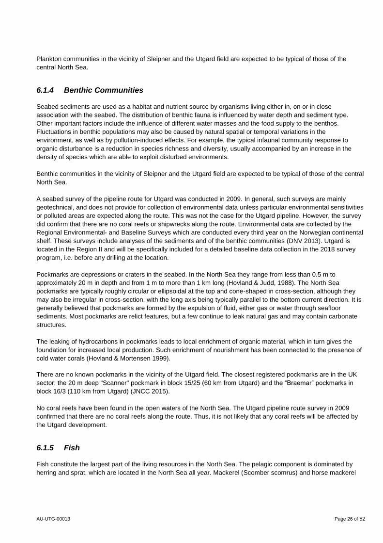
Plankton communities in the vicinity of Sleipner and the Utgard field are expected to be typical of those of the
central North Sea.
6.1.4 Benthic Communities
Seabed sediments are used as a habitat and nutrient source by organisms living either in, on or in close
association with the seabed. The distribution of benthic fauna is influenced by water depth and sediment type.
Other important factors include the influence of different water masses and the food supply to the benthos.
Fluctuations in benthic populations may also be caused by natural spatial or temporal variations in the
environment, as well as by pollution-induced effects. For example, the typical infaunal community response to
organic disturbance is a reduction in species richness and diversity, usually accompanied by an increase in the
density of species which are able to exploit disturbed environments.
Benthic communities in the vicinity of Sleipner and the Utgard field are expected to be typical of those of the central
North Sea.
A seabed survey of the pipeline route for Utgard was conducted in 2009. In general, such surveys are mainly
geotechnical, and does not provide for collection of environmental data unless particular environmental sensitivities
or polluted areas are expected along the route. This was not the case for the Utgard pipeline. However, the survey
did confirm that there are no coral reefs or shipwrecks along the route. Environmental data are collected by the
Regional Environmental- and Baseline Surveys which are conducted every third year on the Norwegian continental
shelf. These surveys include analyses of the sediments and of the benthic communities (DNV 2013). Utgard is
located in the Region II and will be specifically included for a detailed baseline data collection in the 2018 survey
program, i.e. before any drilling at the location.
Pockmarks are depressions or craters in the seabed. In the North Sea they range from less than 0.5 m to
approximately 20 m in depth and from 1 m to more than 1 km long (Hovland & Judd, 1988). The North Sea
pockmarks are typically roughly circular or ellipsoidal at the top and cone-shaped in cross-section, although they
may also be irregular in cross-section, with the long axis being typically parallel to the bottom current direction. It is
generally believed that pockmarks are formed by the expulsion of fluid, either gas or water through seafloor
sediments. Most pockmarks are relict features, but a few continue to leak natural gas and may contain carbonate
structures.
The leaking of hydrocarbons in pockmarks leads to local enrichment of organic material, which in turn gives the
foundation for increased local production. Such enrichment of nourishment has been connected to the presence of
cold water corals (Hovland & Mortensen 1999).
There are no known pockmarks in the vicinity of the Utgard field. The closest registered pockmarks are in the UK
sector; the 20 m deep "Scanner" pockmark in block 15/25 (60 km from Utgard) and the “Braemar” pockmarks in
block 16/3 (110 km from Utgard) (JNCC 2015).
No coral reefs have been found in the open waters of the North Sea. The Utgard pipeline route survey in 2009
confirmed that there are no coral reefs along the route. Thus, it is not likely that any coral reefs will be affected by
the Utgard development.
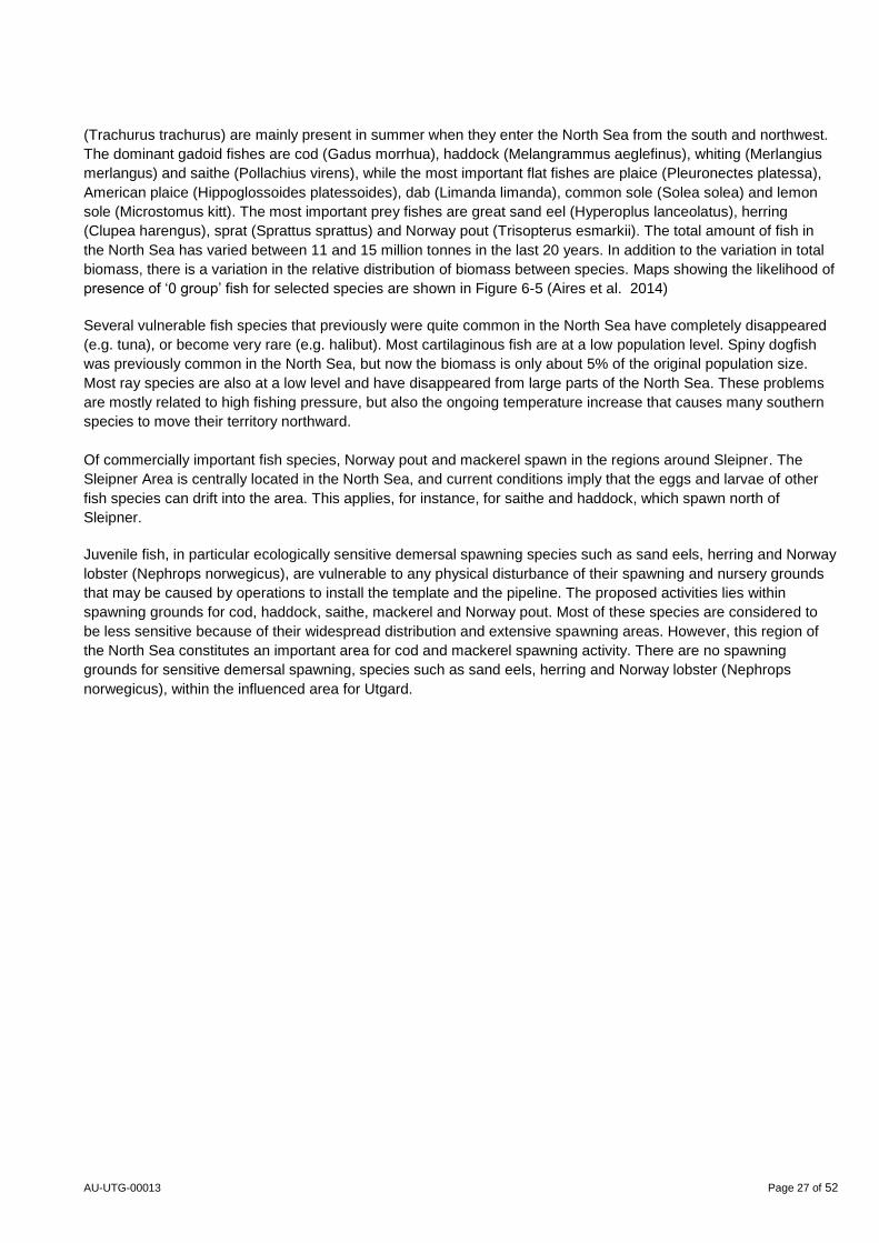
6.1.5 Fish
Fish constitute the largest part of the living resources in the North Sea. The pelagic component is dominated by
herring and sprat, which are located in the North Sea all year. Mackerel (Scomber scomrus) and horse mackerel
AU-UTG-00013 Page 27 of 52
(Trachurus trachurus) are mainly present in summer when they enter the North Sea from the south and northwest.
The dominant gadoid fishes are cod (Gadus morrhua), haddock (Melangrammus aeglefinus), whiting (Merlangius
merlangus) and saithe (Pollachius virens), while the most important flat fishes are plaice (Pleuronectes platessa),
American plaice (Hippoglossoides platessoides), dab (Limanda limanda), common sole (Solea solea) and lemon
sole (Microstomus kitt). The most important prey fishes are great sand eel (Hyperoplus lanceolatus), herring
(Clupea harengus), sprat (Sprattus sprattus) and Norway pout (Trisopterus esmarkii). The total amount of fish in
the North Sea has varied between 11 and 15 million tonnes in the last 20 years. In addition to the variation in total
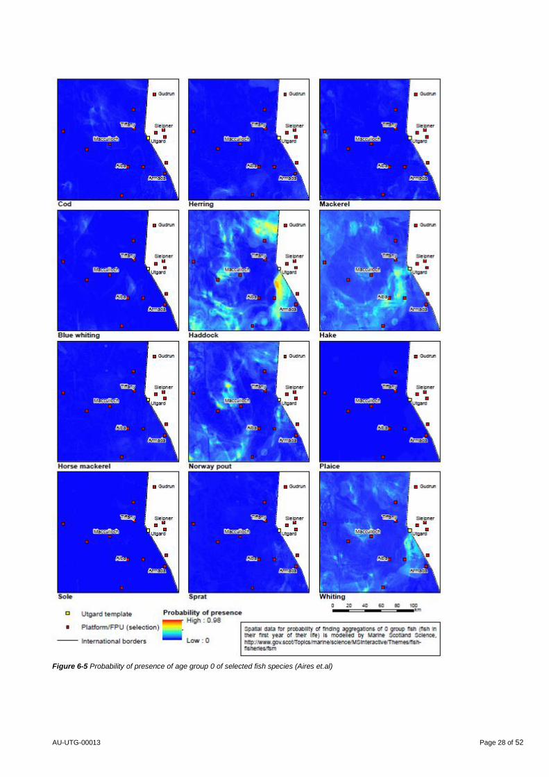
biomass, there is a variation in the relative distribution of biomass between species. Maps showing the likelihood of
presence of ‘0 group’ fish for selected species are shown in Figure 6-5 (Aires et al. 2014)
Several vulnerable fish species that previously were quite common in the North Sea have completely disappeared
(e.g. tuna), or become very rare (e.g. halibut). Most cartilaginous fish are at a low population level. Spiny dogfish
was previously common in the North Sea, but now the biomass is only about 5% of the original population size.
Most ray species are also at a low level and have disappeared from large parts of the North Sea. These problems
are mostly related to high fishing pressure, but also the ongoing temperature increase that causes many southern
species to move their territory northward.
Of commercially important fish species, Norway pout and mackerel spawn in the regions around Sleipner. The
Sleipner Area is centrally located in the North Sea, and current conditions imply that the eggs and larvae of other
fish species can drift into the area. This applies, for instance, for saithe and haddock, which spawn north of
Sleipner.
Juvenile fish, in particular ecologically sensitive demersal spawning species such as sand eels, herring and Norway
lobster (Nephrops norwegicus), are vulnerable to any physical disturbance of their spawning and nursery grounds
that may be caused by operations to install the template and the pipeline. The proposed activities lies within
spawning grounds for cod, haddock, saithe, mackerel and Norway pout. Most of these species are considered to
be less sensitive because of their widespread distribution and extensive spawning areas. However, this region of
the North Sea constitutes an important area for cod and mackerel spawning activity. There are no spawning
grounds for sensitive demersal spawning, species such as sand eels, herring and Norway lobster (Nephrops
norwegicus), within the influenced area for Utgard.
AU-UTG-00013 Page 28 of 52
Figure 6-5 Probability of presence of age group 0 of selected fish species (Aires et.al)
AU-UTG-00013 Page 29 of 52
6.1.6 Seabirds
Internationally important numbers of seabirds breed on the coastal margin of the North Sea, and rely on the marine
North Sea environment for their food supply and habitat.
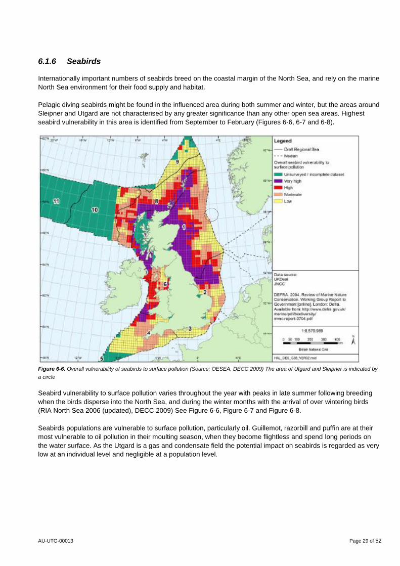
Pelagic diving seabirds might be found in the influenced area during both summer and winter, but the areas around
Sleipner and Utgard are not characterised by any greater significance than any other open sea areas. Highest
seabird vulnerability in this area is identified from September to February (Figures 6-6, 6-7 and 6-8).
Figure 6-6. Overall vulnerability of seabirds to surface pollution (Source: OESEA, DECC 2009) The area of Utgard and Sleipner is indicated by
a circle
Seabird vulnerability to surface pollution varies throughout the year with peaks in late summer following breeding
when the birds disperse into the North Sea, and during the winter months with the arrival of over wintering birds
(RIA North Sea 2006 (updated), DECC 2009) See Figure 6-6, Figure 6-7 and Figure 6-8.
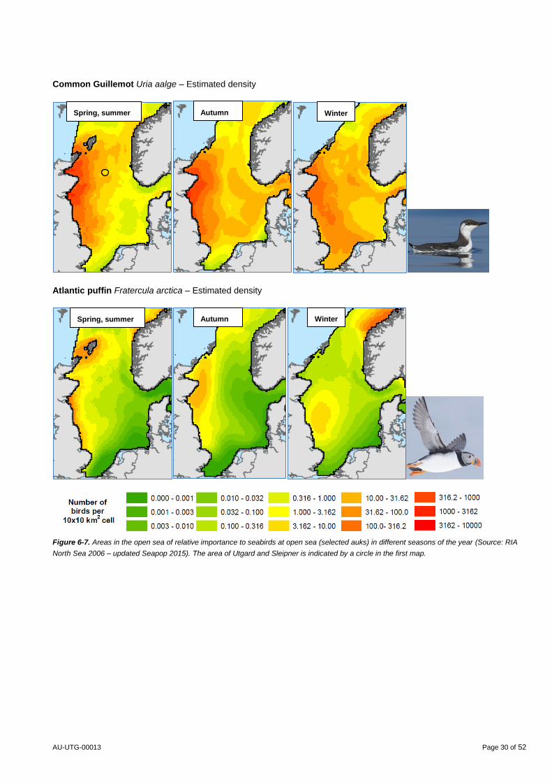
Seabirds populations are vulnerable to surface pollution, particularly oil. Guillemot, razorbill and puffin are at their
most vulnerable to oil pollution in their moulting season, when they become flightless and spend long periods on
the water surface. As the Utgard is a gas and condensate field the potential impact on seabirds is regarded as very
low at an individual level and negligible at a population level.
AU-UTG-00013 Page 30 of 52
Common Guillemot Uria aalge – Estimated density
Atlantic puffin Fratercula arctica – Estimated density
Figure 6-7. Areas in the open sea of relative importance to seabirds at open sea (selected auks) in different seasons of the year (Source: RIA
North Sea 2006 – updated Seapop 2015). The area of Utgard and Sleipner is indicated by a circle in the first map.
Spring, summer
Spring, summer
Winter Autumn
Autumn Winter
AU-UTG-00013 Page 31 of 52
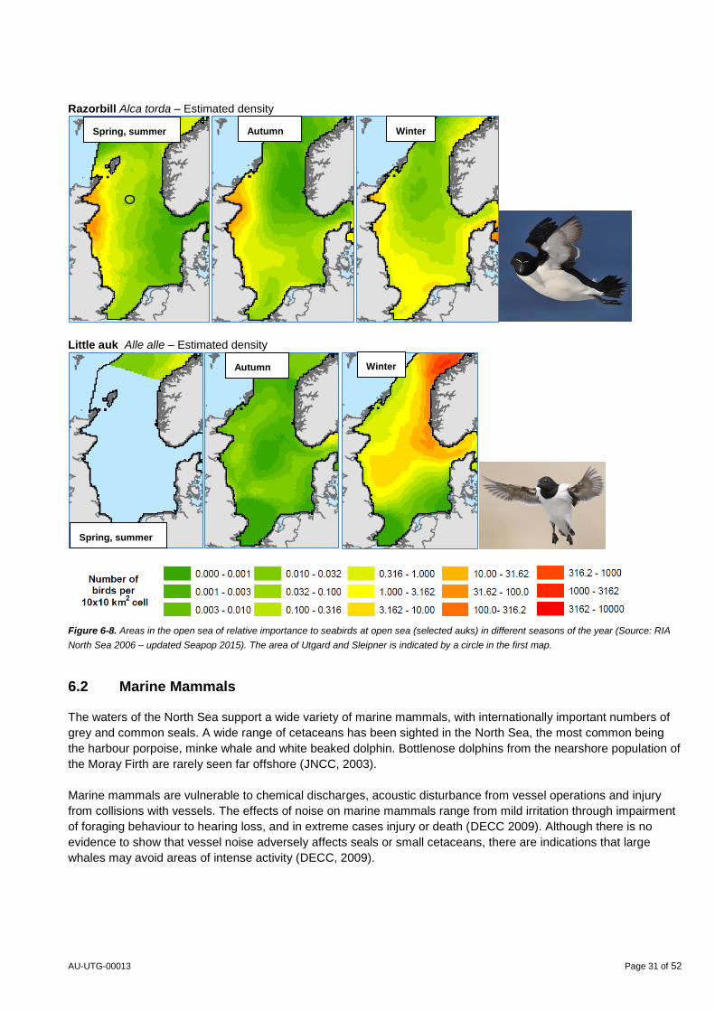
Razorbill Alca torda – Estimated density
Little auk Alle alle – Estimated density
Figure 6-8. Areas in the open sea of relative importance to seabirds at open sea (selected auks) in different seasons of the year (Source: RIA
North Sea 2006 – updated Seapop 2015). The area of Utgard and Sleipner is indicated by a circle in the first map.
6.2 Marine Mammals
The waters of the North Sea support a wide variety of marine mammals, with internationally important numbers of
grey and common seals. A wide range of cetaceans has been sighted in the North Sea, the most common being
the harbour porpoise, minke whale and white beaked dolphin. Bottlenose dolphins from the nearshore population of
the Moray Firth are rarely seen far offshore (JNCC, 2003).
Marine mammals are vulnerable to chemical discharges, acoustic disturbance from vessel operations and injury
from collisions with vessels. The effects of noise on marine mammals range from mild irritation through impairment
of foraging behaviour to hearing loss, and in extreme cases injury or death (DECC 2009). Although there is no
evidence to show that vessel noise adversely affects seals or small cetaceans, there are indications that large
whales may avoid areas of intense activity (DECC, 2009).
Spring, summer Autumn Winter
Spring, summer
Autumn Winter
AU-UTG-00013 Page 32 of 52
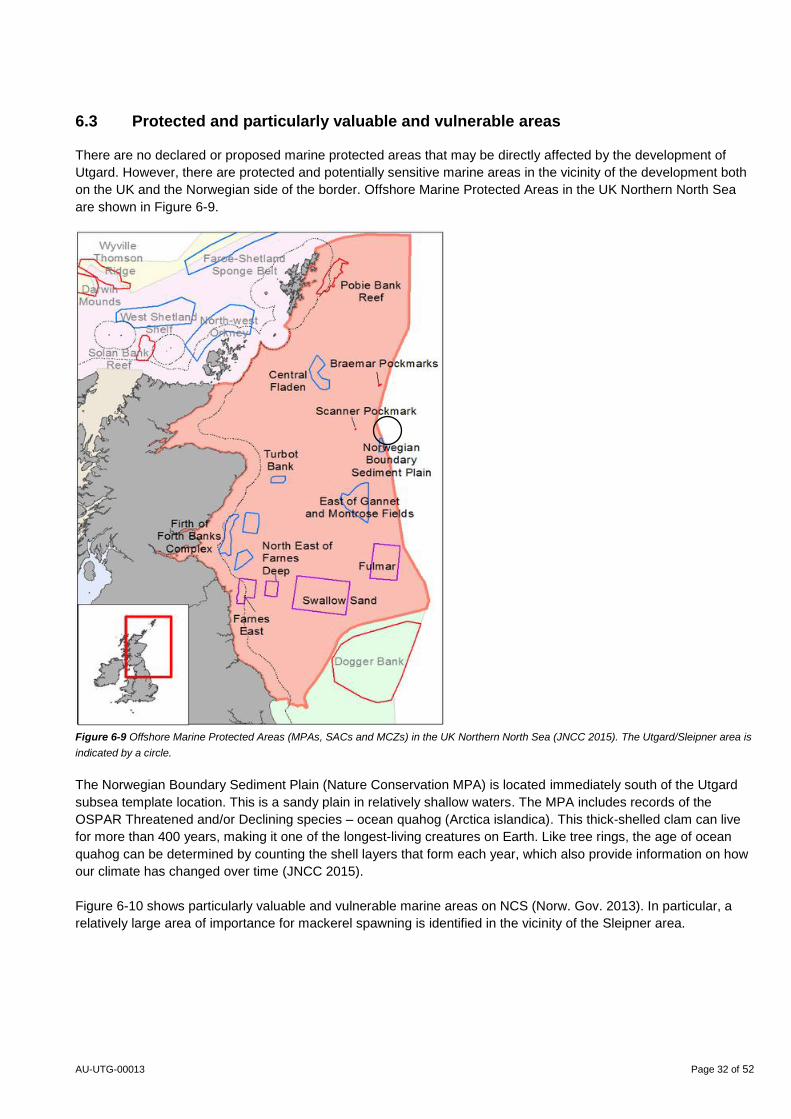
6.3 Protected and particularly valuable and vulnerable areas
There are no declared or proposed marine protected areas that may be directly affected by the development of
Utgard. However, there are protected and potentially sensitive marine areas in the vicinity of the development both
on the UK and the Norwegian side of the border. Offshore Marine Protected Areas in the UK Northern North Sea
are shown in Figure 6-9.
Figure 6-9 Offshore Marine Protected Areas (MPAs, SACs and MCZs) in the UK Northern North Sea (JNCC 2015). The Utgard/Sleipner area is
indicated by a circle.
The Norwegian Boundary Sediment Plain (Nature Conservation MPA) is located immediately south of the Utgard
subsea template location. This is a sandy plain in relatively shallow waters. The MPA includes records of the
OSPAR Threatened and/or Declining species – ocean quahog (Arctica islandica). This thick-shelled clam can live
for more than 400 years, making it one of the longest-living creatures on Earth. Like tree rings, the age of ocean
quahog can be determined by counting the shell layers that form each year, which also provide information on how
our climate has changed over time (JNCC 2015).
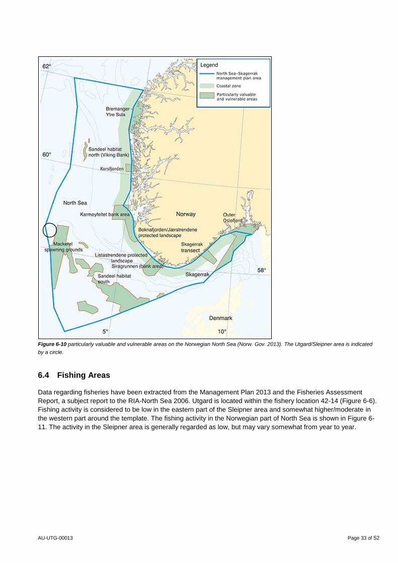
Figure 6-10 shows particularly valuable and vulnerable marine areas on NCS (Norw. Gov. 2013). In particular, a
relatively large area of importance for mackerel spawning is identified in the vicinity of the Sleipner area.
AU-UTG-00013 Page 33 of 52
Figure 6-10 particularly valuable and vulnerable areas on the Norwegian North Sea (Norw. Gov. 2013). The Utgard/Sleipner area is indicated
by a circle.
6.4 Fishing Areas
Data regarding fisheries have been extracted from the Management Plan 2013 and the Fisheries Assessment
Report, a subject report to the RIA-North Sea 2006. Utgard is located within the fishery location 42-14 (Figure 6-6).
Fishing activity is considered to be low in the eastern part of the Sleipner area and somewhat higher/moderate in
the western part around the template. The fishing activity in the Norwegian part of North Sea is shown in Figure 6-
11. The activity in the Sleipner area is generally regarded as low, but may vary somewhat from year to year.
AU-UTG-00013 Page 34 of 52
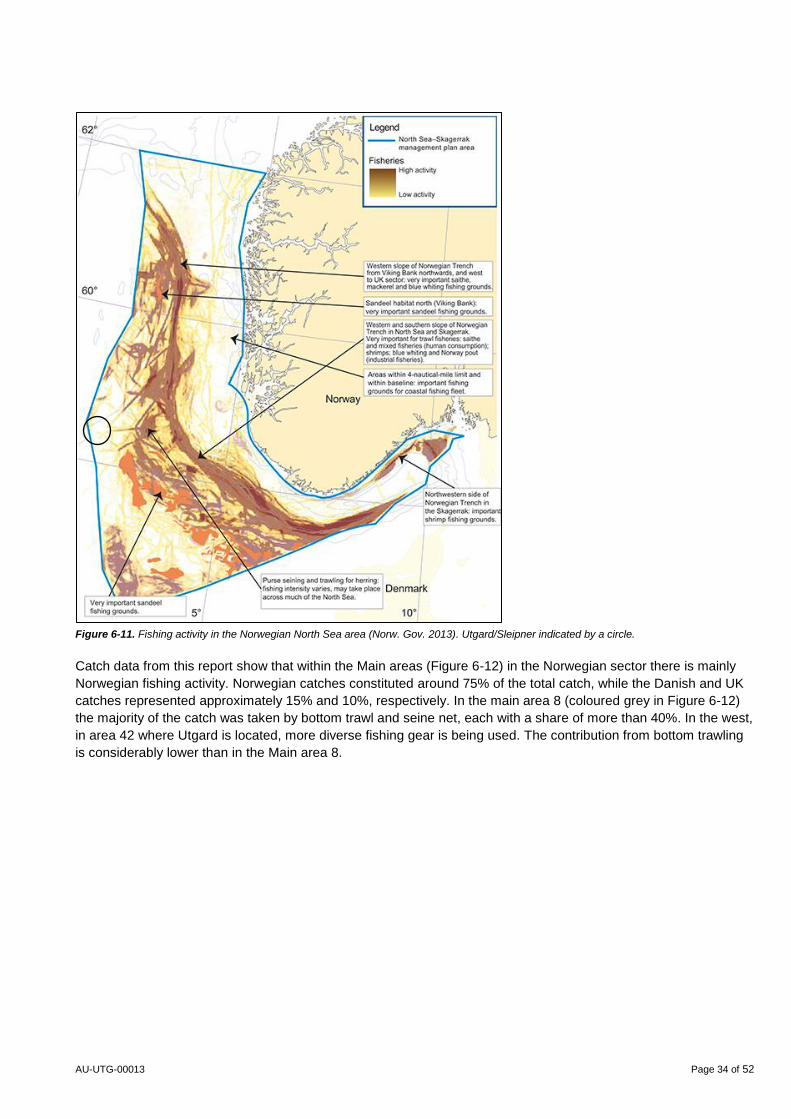
Figure 6-11. Fishing activity in the Norwegian North Sea area (Norw. Gov. 2013). Utgard/Sleipner indicated by a circle.
Catch data from this report show that within the Main areas (Figure 6-12) in the Norwegian sector there is mainly
Norwegian fishing activity. Norwegian catches constituted around 75% of the total catch, while the Danish and UK
catches represented approximately 15% and 10%, respectively. In the main area 8 (coloured grey in Figure 6-12)
the majority of the catch was taken by bottom trawl and seine net, each with a share of more than 40%. In the west,
in area 42 where Utgard is located, more diverse fishing gear is being used. The contribution from bottom trawling
is considerably lower than in the Main area 8.
AU-UTG-00013 Page 35 of 52
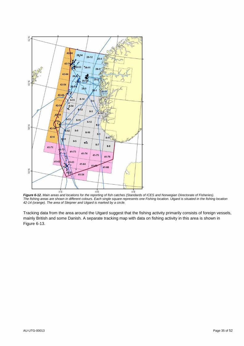
Figure 6-12. Main areas and locations for the reporting of fish catches (Standards of ICES and Norwegian Directorate of Fisheries). The fishing areas are shown in different colours. Each single square represents one Fishing location. Utgard is situated in the fishing location 42-14 (orange). The area of Sleipner and Utgard is marked by a circle.
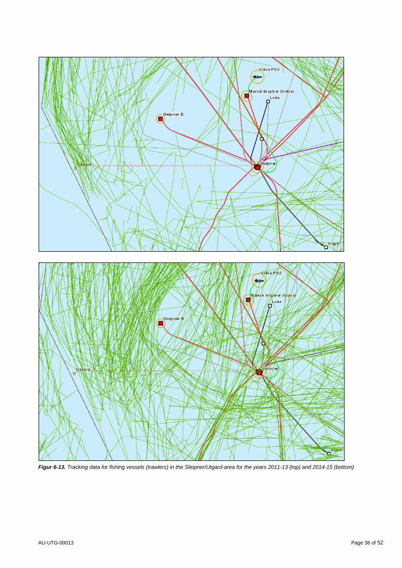
Tracking data from the area around the Utgard suggest that the fishing activity primarily consists of foreign vessels,
mainly British and some Danish. A separate tracking map with data on fishing activity in this area is shown in
Figure 6-13.
AU-UTG-00013 Page 36 of 52
Figur 6-13. Tracking data for fishing vessels (trawlers) in the Sleipner/Utgard-area for the years 2011-13 (top) and 2014-15 (bottom)
AU-UTG-00013 Page 37 of 52
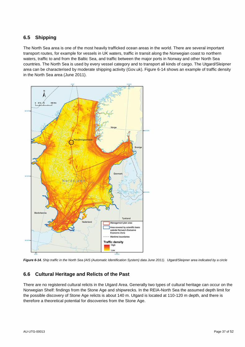
6.5 Shipping
The North Sea area is one of the most heavily trafficked ocean areas in the world. There are several important
transport routes, for example for vessels in UK waters, traffic in transit along the Norwegian coast to northern
waters, traffic to and from the Baltic Sea, and traffic between the major ports in Norway and other North Sea
countries. The North Sea is used by every vessel category and to transport all kinds of cargo. The Utgard/Sleipner
area can be characterised by moderate shipping activity (Gov.uk). Figure 6-14 shows an example of traffic density
in the North Sea area (June 2011).
Figure 6-14. Ship traffic in the North Sea (AIS (Automatic Identification System) data June 2011). Utgard/Sleipner area indicated by a circle
6.6 Cultural Heritage and Relicts of the Past
There are no registered cultural relicts in the Utgard Area. Generally two types of cultural heritage can occur on the
Norwegian Shelf: findings from the Stone Age and shipwrecks. In the REIA-North Sea the assumed depth limit for
the possible discovery of Stone Age relicts is about 140 m. Utgard is located at 110-120 m depth, and there is
therefore a theoretical potential for discoveries from the Stone Age.
AU-UTG-00013 Page 38 of 52
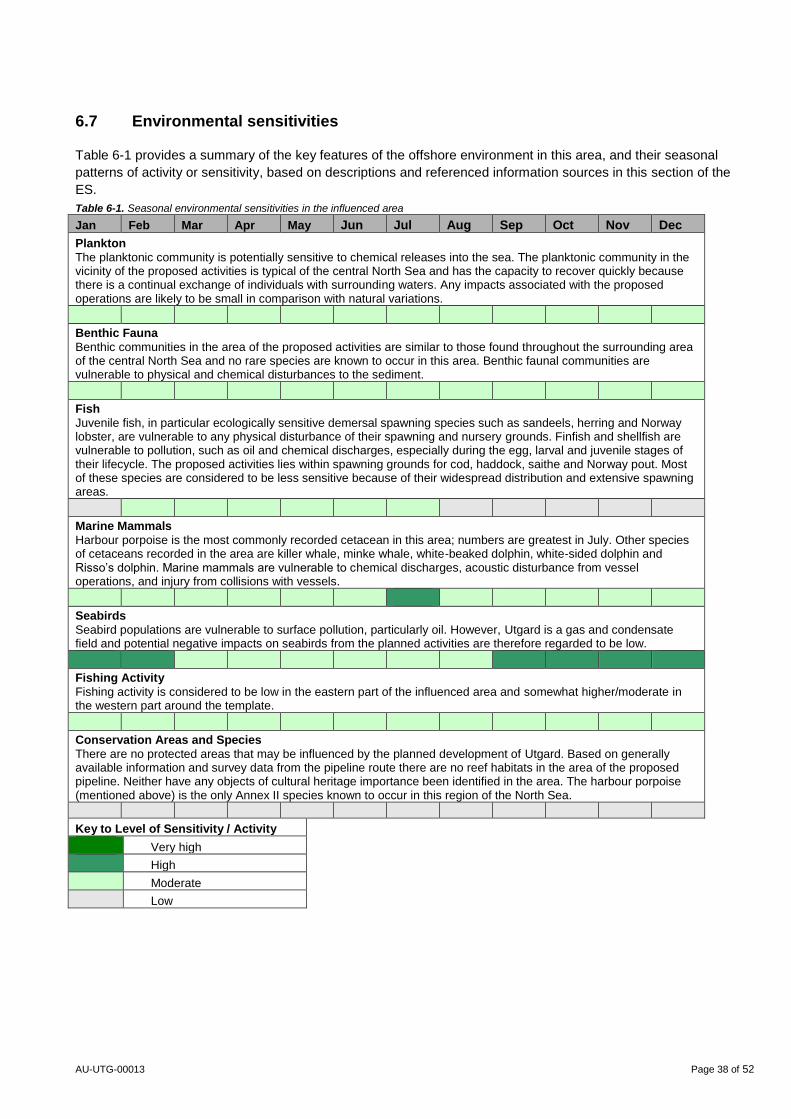
6.7 Environmental sensitivities
Table 6-1 provides a summary of the key features of the offshore environment in this area, and their seasonal
patterns of activity or sensitivity, based on descriptions and referenced information sources in this section of the
ES.
Table 6-1. Seasonal environmental sensitivities in the influenced area
Jan Feb Mar Apr May Jun Jul Aug Sep Oct Nov Dec
Plankton
The planktonic community is potentially sensitive to chemical releases into the sea. The planktonic community in the vicinity of the proposed activities is typical of the central North Sea and has the capacity to recover quickly because there is a continual exchange of individuals with surrounding waters. Any impacts associated with the proposed operations are likely to be small in comparison with natural variations.
Benthic Fauna
Benthic communities in the area of the proposed activities are similar to those found throughout the surrounding area of the central North Sea and no rare species are known to occur in this area. Benthic faunal communities are vulnerable to physical and chemical disturbances to the sediment.
Fish
Juvenile fish, in particular ecologically sensitive demersal spawning species such as sandeels, herring and Norway lobster, are vulnerable to any physical disturbance of their spawning and nursery grounds. Finfish and shellfish are vulnerable to pollution, such as oil and chemical discharges, especially during the egg, larval and juvenile stages of their lifecycle. The proposed activities lies within spawning grounds for cod, haddock, saithe and Norway pout. Most of these species are considered to be less sensitive because of their widespread distribution and extensive spawning areas.
Marine Mammals
Harbour porpoise is the most commonly recorded cetacean in this area; numbers are greatest in July. Other species of cetaceans recorded in the area are killer whale, minke whale, white-beaked dolphin, white-sided dolphin and Risso’s dolphin. Marine mammals are vulnerable to chemical discharges, acoustic disturbance from vessel operations, and injury from collisions with vessels.
Seabirds
Seabird populations are vulnerable to surface pollution, particularly oil. However, Utgard is a gas and condensate field and potential negative impacts on seabirds from the planned activities are therefore regarded to be low.
Fishing Activity
Fishing activity is considered to be low in the eastern part of the influenced area and somewhat higher/moderate in the western part around the template.
Conservation Areas and Species
There are no protected areas that may be influenced by the planned development of Utgard. Based on generally available information and survey data from the pipeline route there are no reef habitats in the area of the proposed pipeline. Neither have any objects of cultural heritage importance been identified in the area. The harbour porpoise (mentioned above) is the only Annex II species known to occur in this region of the North Sea.
Key to Level of Sensitivity / Activity
Very high
High
Moderate
Low

AU-UTG-00013 Page 39 of 52
7 Potential Environmental Impacts
This chapter gives an estimate for emissions to air and discharges to sea from Utgard. It also describes the
physical impacts on the seabed from the planned interventions and installation works and the physical presence of
the subsea infrastructure. The potential environmental impacts are described. Accidental events are thoroughly
considered in cognisance of the Supplementary Guidance issued by DECC to the operators on UKCS following the
Deepwater Horizon accident.
In general the development of Utgard will result in only minor potential environmental impact. During the
construction phase there will be activities from vessels and drilling close to the UK border. During the production
phase all emissions to air will come from the existing Sleipner complex. Produced water from Utgard will be sent for
injection together with the produced water from the Sleipner fields.
7.1 Emissions to Air
Sleipner development production has fallen below plateau levels, and processing of the well stream from Utgard
will use free capacity on the Sleipner complex. This implies that Utgard will not cause any increase of emissions to
air from Sleipner compared with the existing conditions. No new process equipment or power producing equipment
will be needed for production of the Utgard reserves.
The well stream in the Utgard field has high CO2 content and will be routed through the CO2-removal facilities at
SLT in order to reduce the CO2 content. Separated CO2 will be injected into the subsurface Utsira-formation for
permanent disposal - about 1 million tonnes of CO2 from the Sleipner field have been injected every year since
start-up of the Sleipner West field in 1996. After CO2-removal the gas from Utgard will be blended into other gas
volumes at the Sleipner facilities before it is exported to the market.
The following activities will cause emissions to air:
Drilling and well operations
Marine operations (installation of template, pipeline, etc.)
Operation/processing at Sleipner
Injection of CO2 and produced water
Transport of gas and condensate
For drilling and completion, a separate, drilling rig will be used (probably a semi-semisubmersible unit, although a
jack-up unit could be used). Emissions to air will occur from the drilling unit. The drilling unit will produce emissions
of CO2 and NOX, as well as smaller amounts of SO2 from diesel engines. Testing and cleaning of the wells will be
routed to the inlet separator at the SLT platform, and hence, no emissions to air from testing and cleaning will take
place at the drilling rig.
Marine operations in connection with the installation of subsea equipment and pipeline laying and cables will give
emissions of CO2, NOX and SO2 from diesel engines on the transport and construction vessels.
In the operational phase, all emissions to air will occur from the Sleipner installations. The main components that
will be released into the air are CO2, NOx, CH4, nmVOC (non-methane Volatile Organic Compounds), from the
following sources:
Gas turbines
Diesel engines (fire water pumps and emergency generators etc.)
Diffuse emissions from processing
Emissions from flaring
AU-UTG-00013 Page 40 of 52
Processing, injection and transportation require energy, which in turn will lead to emissions. In particular the
compression and pumping of gas and condensate for export requires energy. However, there will be no need for
installation of new power production or process equipment at Sleipner as a result of the development of the Utgard.
There are 11 turbines on the Sleipner Installations. Sleipner A has 3 Dual Fuel (DF) LM2500 generator drivers, of
which one is prepared for low-NOX (DLE). Sleipner A has 5 Single Fuel (SF) LM2500 PE compressor drivers.
Sleipner T has 3 SF LM2500 PE compressor drivers which all are prepared for low- NOX. At present none of the
turbines have low- NOX technology. The Norwegian Environmental Directorate stated in the current Frame
Discharge Permit for Sleipner that they consider the technology used in the energy plants on the Sleipner Field as
satisfactory in relation to Best Available Techniques (BAT).
The development of Utgard will use the existing processing capacity and export capacity at Sleipner, and thus
contribute to the total emissions from the Sleipner installations.
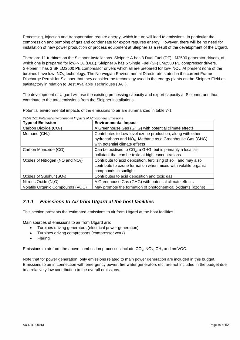
Potential environmental impacts of the emissions to air are summarized in table 7-1. Table 7-1: Potential Environmental Impacts of Atmospheric Emissions
Type of Emission Environmental Impact
Carbon Dioxide (CO2) A Greenhouse Gas (GHG) with potential climate effects
Methane (CH4) Contributes to Low-level ozone production, along with other
hydrocarbons and NOX. Methane as a Greenhouse Gas (GHG)
with potential climate effects
Carbon Monoxide (CO) Can be oxidised to CO2, a GHG, but is primarily a local air
pollutant that can be toxic at high concentrations.
Oxides of Nitrogen (NO and NO2) Contribute to acid deposition, fertilizing of soil, and may also
contribute to ozone formation when mixed with volatile organic
compounds in sunlight.
Oxides of Sulphur (SOX) Contributes to acid deposition and toxic gas.
Nitrous Oxide (N2O) A Greenhouse Gas (GHG) with potential climate effects
Volatile Organic Compounds (VOC) May promote the formation of photochemical oxidants (ozone)
7.1.1 Emissions to Air from Utgard at the host facilities
This section presents the estimated emissions to air from Utgard at the host facilities.
Main sources of emissions to air from Utgard are:
Turbines driving generators (electrical power generation)
Turbines driving compressors (compressor work)
Flaring
Emissions to air from the above combustion processes include CO2, NOX, CH4 and nmVOC.
Note that for power generation, only emissions related to main power generation are included in this budget.
Emissions to air in connection with emergency power, fire water generators etc. are not included in the budget due
to a relatively low contribution to the overall emissions.
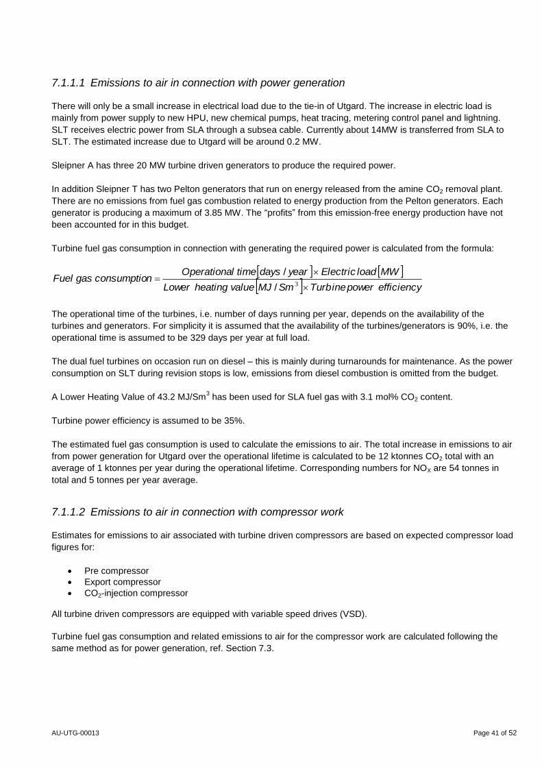
AU-UTG-00013 Page 41 of 52
7.1.1.1 Emissions to air in connection with power generation
There will only be a small increase in electrical load due to the tie-in of Utgard. The increase in electric load is
mainly from power supply to new HPU, new chemical pumps, heat tracing, metering control panel and lightning.
SLT receives electric power from SLA through a subsea cable. Currently about 14MW is transferred from SLA to
SLT. The estimated increase due to Utgard will be around 0.2 MW.
Sleipner A has three 20 MW turbine driven generators to produce the required power.
In addition Sleipner T has two Pelton generators that run on energy released from the amine CO2 removal plant.
There are no emissions from fuel gas combustion related to energy production from the Pelton generators. Each
generator is producing a maximum of 3.85 MW. The “profits” from this emission-free energy production have not
been accounted for in this budget.
Turbine fuel gas consumption in connection with generating the required power is calculated from the formula:
efficiencypowerTurbineSmMJvalueheatingLower
MWloadElectricyeardaystimelOperationanconsumptiogasFuel
3/
/
The operational time of the turbines, i.e. number of days running per year, depends on the availability of the
turbines and generators. For simplicity it is assumed that the availability of the turbines/generators is 90%, i.e. the
operational time is assumed to be 329 days per year at full load.
The dual fuel turbines on occasion run on diesel – this is mainly during turnarounds for maintenance. As the power
consumption on SLT during revision stops is low, emissions from diesel combustion is omitted from the budget.
A Lower Heating Value of 43.2 MJ/Sm3 has been used for SLA fuel gas with 3.1 mol% CO2 content.
Turbine power efficiency is assumed to be 35%.
The estimated fuel gas consumption is used to calculate the emissions to air. The total increase in emissions to air
from power generation for Utgard over the operational lifetime is calculated to be 12 ktonnes CO2 total with an
average of 1 ktonnes per year during the operational lifetime. Corresponding numbers for NOX are 54 tonnes in
total and 5 tonnes per year average.
7.1.1.2 Emissions to air in connection with compressor work
Estimates for emissions to air associated with turbine driven compressors are based on expected compressor load
figures for:
Pre compressor
Export compressor
CO2-injection compressor All turbine driven compressors are equipped with variable speed drives (VSD).
Turbine fuel gas consumption and related emissions to air for the compressor work are calculated following the
same method as for power generation, ref. Section 7.3.
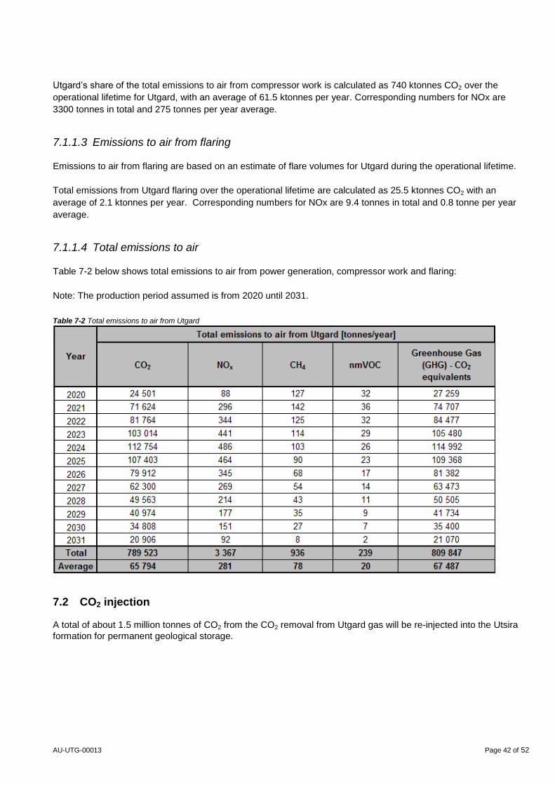
AU-UTG-00013 Page 42 of 52
Utgard’s share of the total emissions to air from compressor work is calculated as 740 ktonnes CO2 over the
operational lifetime for Utgard, with an average of 61.5 ktonnes per year. Corresponding numbers for NOx are
3300 tonnes in total and 275 tonnes per year average.
7.1.1.3 Emissions to air from flaring
Emissions to air from flaring are based on an estimate of flare volumes for Utgard during the operational lifetime.
Total emissions from Utgard flaring over the operational lifetime are calculated as 25.5 ktonnes CO2 with an
average of 2.1 ktonnes per year. Corresponding numbers for NOx are 9.4 tonnes in total and 0.8 tonne per year
average.
7.1.1.4 Total emissions to air
Table 7-2 below shows total emissions to air from power generation, compressor work and flaring:
Note: The production period assumed is from 2020 until 2031.
Table 7-2 Total emissions to air from Utgard
7.2 CO2 injection
A total of about 1.5 million tonnes of CO2 from the CO2 removal from Utgard gas will be re-injected into the Utsira
formation for permanent geological storage.
AU-UTG-00013 Page 43 of 52
7.3 Discharges to Sea
Development and operation of Utgard will cause discharges to sea, normally comprising:
Discharges from drilling and well operations (water based drilling fluid and cuttings)
Discharges of control fluid, from the operations of valves on subsea installations
Discharges from the commissioning of pipelines (RFO – Ready For Operation)
Produced water from Utgard will be re-injected into the Utsira subsurface formation after treatment, and will
normally not be discharged to sea. Note: Re-injection of produced water started at the Sleipner field in 2009, and
the up-time of this system has been above 97%.
There might be a minor increase in other operational discharges from Sleipner T and Sleipner A, caused by
increased processing (e.g. cooling water).
Discharges to sea from the drilling of the two wells at Utgard are documented in Section 3.5.3 of this document,
see table 3-3.
The environmental impact associated with discharges from the drilling will largely be restricted to the direct effect
on benthic animals as a result of the physical coverage of bottom sediments. The main ingredients in water based
drilling fluid are not considered toxic, but the particles may have some physical effect on the planktonic organisms
and the benthic animal society. Such consequences are local. When drilling with oil based mud, cuttings will not be
released to the sea, but shipped to shore for final handling, treatment and disposal.
In connection with the preparation and tie in of pipelines, there will be discharges of water containing chemicals
that have been used to prevent corrosion/fouling, and the dyes used for pressure testing and leakage detection.
The discharges will have local and short term effects only.
The control system at Utgard will be an integrated part of the Sleipner control system. This is an open hydraulic
system with discharge to sea. The hydraulic fluid (Oceanic HW 443 ND) in this system is judged as environmentally
acceptable by Norwegian authorities (yellow environmental category). Based on the experience from a similar
subsea installation a yearly discharge of approximately 1 m3 of control fluid is expected.
In summary, no significant environmental impacts are expected from the planned discharges to sea from the
development of Utgard.
7.3.1 Discharges to Sea from Utgard at the host facilities
This section presents the estimated discharges to sea from Utgard at the host facilities.
Estimated discharges of produced water to sea are given in Section 4.4 of this document, see Table 4-3.
The produced water from Utgard will be separated from gas and condensate in the inlet separator at SLT and will
be sent to the produced water flash drum which includes automatic skimming and removal of the oil phase
separated by flotation. Produced water at Sleipner (including Utgard) will be re-injected into the Utsira formation
after treatment. The produced water injection system up-time has been above 97% for the entire period since re-
injection started in 2009, i.e. less than 3% of the produced water has been discharged overboard during these
years. The very limited produced water discharged to sea related to the Utgard production will contain small
amounts of oil and scale inhibitor.
AU-UTG-00013 Page 44 of 52
The following oil in water and scale inhibitor concentrations, based on historical data from 2010-2014, can be
assumed:
Oil in produced water: 29 mg/l
Scale inhibitor in produced water: 175 mg/l
The discharge permit issued by the Norwegian Environmental Directorate sets a discharge limitation of 1100 kg of
oil to sea per year from the Sleipner installations in total. In 2015 the actual discharge from the Sleipner field with
all its satellites was reported around 650 kg. The concentrations of oil or other components in the produced water
discharge are not specifically regulated by the discharge permit.
7.4 Waste Handling
Since generation of different types of waste in connection with operations and maintenance is unavoidable the
primary aim regarding waste handling during Utgard operations is to minimise the amounts of waste and to
maximize the degree of reprocessing, reuse or recycling.
Utgard is expected to generate a small increase in waste production, which will be handled by the existing waste
segregation system on Sleipner. An environmental station is located in M12 on SLT main deck, where segregation
of the different types of waste is possible, including hazardous waste. On SLA there are several environmental
stations, with the main station for segregation of hazardous waste located on the Weather Deck.
During the installation phase there might be need for extended waste disposal capacity. In this case, skips will be
ordered for waste handling as deemed necessary and located in laydown areas on lower and upper mezzanine
decks or weather deck.
Produced sand shall either be handled as hazardous waste or cleaned and discharged to sea according to
Norwegian regulations. Furthermore, according to the Norwegian regulations, sand shall not be discharged to sea if
the oil content is more than ten grams per kilogram of dry matter. Sand from Utgard will be trapped in Alfa Nord
sand trap and drained to drip tray. The rest of the sand will be sedimented in inlet separator G-20-VA01. There is
no sand jetting system in G-20-VA01, hence trapped sand has to be dug out for disposal during maintenance
turnarounds. Sand production from Utgard is expected to be low.
7.5 Physical Impacts and Presence of Subsea Infrastructure
Physical impacts will be related to installation of template, drilling of two wells and installation of 21 km of pipeline
and umbilical. In the production phase the Utgard template and the 21 km pipeline and umbilical will represent a
physical presence at the seabed.
Marine Protected Areas
No marine protected areas are directly affected by the Utgard development. However, there are protected and
potentially sensitive marine areas in the vicinity of the development both on the UK and the Norwegian side of the
border. The planned activity at Utgard is limited, and no significant impacts in these areas are anticipated.
Fisheries
Field activities connected to drilling, installation of subsea facilities and laying of pipelines, can potentially impact
fishing more than the production phase operations. These activities can create a temporary area of exclusion for
fishing vessels that moves with the ongoing work. However, since these activities take place within a limited time
period, they are not expected to cause any significant loss of catch.
AU-UTG-00013 Page 45 of 52
Exclusion from areas of sea by the presence of rigs or installations could result in effects on commercial fishing, as
could the presence of snagging hazards associated with pipelines or debris. However, the small scale of the Utgard
infrastructures implies that this is unlikely to cause significant economic impacts. In addition, the template and
pipeline will be over-trawlable.
Shipping
The Utgard/Sleipner area is characterised by moderate shipping activity. As discussed above for fisheries, field
activities at Utgard can create a temporary area of exclusion for shipping that moves with the ongoing work.
However, since these activities take place within a limited time period, they are not expected to cause any
significant economic impact.
Corals
Cold water corals are sensitive to physical interference from seabed intervention work. However, no cold water
coral reefs have been found in the open waters of the North Sea. The likelihood of corals being affected by the
planned activities is therefore minimal.
Cultural Heritage and Relicts from the Past
Activities affecting the seabed may cause direct or indirect impact on cultural heritage and relicts from the past.
This relates mainly to activities such as the placement of wells / subsea templates and the laying of pipelines.
Investigations of the locations and corridors for template and pipelines will reveal possible discoveries of cultural
relics. A subsea survey of the Utgard pipeline corridor in 2009 did not reveal any such objects. If cultural relics are
found in the impacted area, the Norwegian cultural heritage authorities will be contacted and further handling of the
discoveries will be clarified.
7.6 Accidental Emissions and Discharges
Accidental emissions and discharges may occur due to accidents in the following categories:
Blow-out from drilling rig or field installations during operation
Accidental emissions from drilling rig
Leaks from pipelines
Leaks from subsea installations
Leaks from processing
The most severe environmental impacts are generally associated with acute accidental discharges of oil and the
subsequent damages of seabirds. For gas/condensate fields like Utgard, the potential impacts from possible acute
discharges are considerably less severe.
The following assessment has given particular attention to the matters raised in the Supplementary Guidance
issued by the Department of Energy and Climate Change (DECC) following the Macondo well incident in the Gulf
of Mexico (Deepwater Horizon).
The main driver, as all infrastructure and activities are on the Norwegian side of the border, is meeting the
Norwegian regulatory requirements for documentation of environmental risk from accidental spills, and the
corresponding design and dimensioning of the oil spill response system.
Utgard is included in the latest update of the Environmental Risk Analysis for the Sleipner Field (DNV 2009). This
analysis was specifically reviewed and re-confirmed in 2014. The analysis is based on the discharge frequency for
AU-UTG-00013 Page 46 of 52
activities on the installations Sleipner A, Sleipner B, Sigyn, Alfa Nord and Utgard. The production at the Sleipner
field is primarily gas and condensate, one single well produces light oil (Sigyn). A typical light oil (density 793
kg/m3) has been assumed for the oil drift modelling throughout the analysis. For Utgard this is a conservative
assumption.
Both surface and subsea blow-outs have been considered. In both cases 5 different blow-out durations and 5
different blow-out rates have been considered. The longest duration is related to the time it would take to drill a
relief well and kill the well, which is estimated to be 98 days. The duration is based on average drilling time for a
well in the Sleipner area, and includes the time needed for mobilisation of the rig.
Specific modelling has been conducted to establish oil-slick thickness when surfacing from a subsea blow-out
case. In the oil spill modelling for oil on the sea surface, oil drift statistics were generated for 3600 randomly
selected simulations (different starting dates) for all duration and rate combinations, throughout the year.
Blowout frequencies are derived from available recognized statistics, e.g. the Scandpower Risk Management-
Blowout and Well Release Frequencies and the SINTEF-Offshore Blowout Database.
Probability distributions for different blow-out rates and durations for a subsea and a surface blow-out scenario are
shown in Table 7-3.
Table 7-3. Probability distribution for different combinations of blow-out rates and durations for blow-out scenarios subsea and at the sea
surface. Input to oil drift modelling for the Sleipner field. (StatoilHydro 2009)
Scenario Rate (Sm3/d)
Duration (days)
2 5 15 35 98
Surface 50 0,342 0,120 0,090 0,030 0,018
Surface 200 0,137 0,048 0,036 0,012 0,007
Surface 450 0,034 0,012 0,009 0,003 0,002
Surface 3300 0.051 0,018 0,014 0,005 0,003
Surface 9500 0,006 0,002 0,002 0,001 0,000
Subsea 50 0,193 0,085 0,089 0,042 0,061
Subsea 275 0,160 0,070 0,074 0,035 0,051
Subsea 830 0,008 0,004 0,004 0,002 0,003
Subsea 3300 0,025 0,011 0,011 0,005 0,008
Subsea 9500 0,025 0,011 0,011 0,005 0,008
The probability distribution data shows that the worst case scenario has a negligible to nil probability of occurrence
compared with other more realistic combinations of rates and duration. A weighted average duration can be
deduced from the data to be around 10 days for the surface blow-out case and 20 days for the subsea blow-out
case. Similarly the weighted average blowout rates would be around 500 Sm3/d for the surface case and 900
Sm3/d subsea.
Oil drift modelling results are shown in Figure 7-1 and Figure 7-2. The results of the oil drift modelling clearly show
that there is a higher probability of sea-surface oiling in an easterly direction rather than in a westerly direction. The
modelling shows that UK waters may be impacted in an accidental oil spill scenario from the Sleipner area,
although at a lower probability than Norwegian waters.
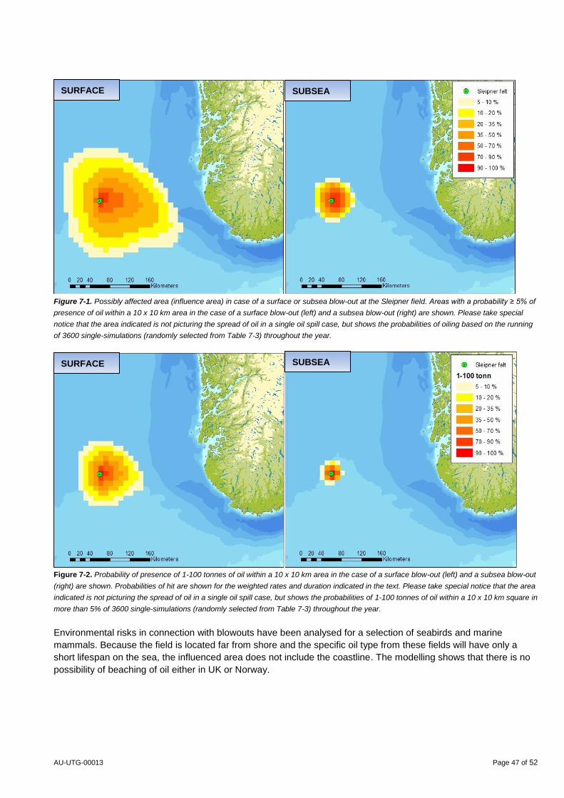
AU-UTG-00013 Page 47 of 52
Figure 7-1. Possibly affected area (influence area) in case of a surface or subsea blow-out at the Sleipner field. Areas with a probability ≥ 5% of
presence of oil within a 10 x 10 km area in the case of a surface blow-out (left) and a subsea blow-out (right) are shown. Please take special
notice that the area indicated is not picturing the spread of oil in a single oil spill case, but shows the probabilities of oiling based on the running
of 3600 single-simulations (randomly selected from Table 7-3) throughout the year.
Figure 7-2. Probability of presence of 1-100 tonnes of oil within a 10 x 10 km area in the case of a surface blow-out (left) and a subsea blow-out
(right) are shown. Probabilities of hit are shown for the weighted rates and duration indicated in the text. Please take special notice that the area
indicated is not picturing the spread of oil in a single oil spill case, but shows the probabilities of 1-100 tonnes of oil within a 10 x 10 km square in
more than 5% of 3600 single-simulations (randomly selected from Table 7-3) throughout the year.
Environmental risks in connection with blowouts have been analysed for a selection of seabirds and marine
mammals. Because the field is located far from shore and the specific oil type from these fields will have only a
short lifespan on the sea, the influenced area does not include the coastline. The modelling shows that there is no
possibility of beaching of oil either in UK or Norway.
SURFACE
SURFACE
SUBSEA
SUBSEA
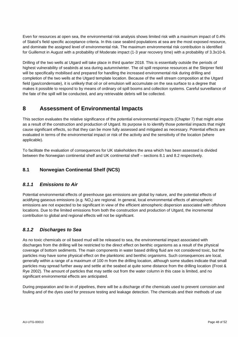
AU-UTG-00013 Page 48 of 52
Even for resources at open sea, the environmental risk analysis shows limited risk with a maximum impact of 0.4%
of Statoil’s field specific acceptance criteria. In this case seabird populations at sea are the most exposed resource,
and dominate the assigned level of environmental risk. The maximum environmental risk contribution is identified
for Guillemot in August with a probability of Moderate impact (1-3 year recovery time) with a probability of 3.3x10⁻⁶.
Drilling of the two wells at Utgard will take place in third quarter 2018. This is essentially outside the periods of
highest vulnerability of seabirds at sea during autumn/winter. The oil spill response resources at the Sleipner field
will be specifically mobilised and prepared for handling the increased environmental risk during drilling and
completion of the two wells at the Utgard template location. Because of the well stream composition at the Utgard
field (gas/condensate), it is unlikely that oil or oil emulsion will accumulate on the sea surface to a degree that
makes it possible to respond to by means of ordinary oil spill booms and collection systems. Careful surveillance of
the fate of the spill will be conducted, and any retrievable debris will be collected.
8 Assessment of Environmental Impacts
This section evaluates the relative significance of the potential environmental impacts (Chapter 7) that might arise
as a result of the construction and production of Utgard. Its purpose is to identify those potential impacts that might
cause significant effects, so that they can be more fully assessed and mitigated as necessary. Potential effects are
evaluated in terms of the environmental impact or risk of the activity and the sensitivity of the location (where
applicable).
To facilitate the evaluation of consequences for UK stakeholders the area which has been assessed is divided
between the Norwegian continental shelf and UK continental shelf – sections 8.1 and 8.2 respectively.
8.1 Norwegian Continental Shelf (NCS)
8.1.1 Emissions to Air
Potential environmental effects of greenhouse gas emissions are global by nature, and the potential effects of
acidifying gaseous emissions (e.g. NOx) are regional. In general, local environmental effects of atmospheric
emissions are not expected to be significant in view of the efficient atmospheric dispersion associated with offshore
locations. Due to the limited emissions from both the construction and production of Utgard, the incremental
contribution to global and regional effects will not be significant.
8.1.2 Discharges to Sea
As no toxic chemicals or oil based mud will be released to sea, the environmental impact associated with
discharges from the drilling will be restricted to the direct effect on benthic organisms as a result of the physical
coverage of bottom sediments. The main components in water based drilling fluid are not considered toxic, but the
particles may have some physical effect on the planktonic and benthic organisms. Such consequences are local,
generally within a range of a maximum of 100 m from the drilling location, although some studies indicate that small
particles may spread further away and settle at the seabed at quite some distance from the drilling location (Frost &
Rye 2002). The amount of particles that may settle out from the water column in this case is limited, and no
significant environmental effects are anticipated.
During preparation and tie-in of pipelines, there will be a discharge of the chemicals used to prevent corrosion and
fouling and of the dyes used for pressure testing and leakage detection. The chemicals and their methods of use
AU-UTG-00013 Page 49 of 52
are selected to reduce discharge volumes and environmental risk, and the discharge is expected to provide only
local impacts within a limited time period. Those organisms that would be at risk include planktonic organisms (i.e.
those drifting in the near-seabed currents); epibenthic organisms (e.g. demersal fish and shellfish) and sediment
dwelling filter feeders.
Produced water at Sleipner (including Utgard produced water) will be re-injected into the Utsira formation after
treatment. The injection regularity (up-time) for the produced water has been above 97% for the period 2009-2015,
i.e. less than 3% of the produced water has been discharged overboard over these years. The discharge permit
limitation for discharge to sea of oil with produced water is set at a maximum of 1100 kg oil/year from the Sleipner
field in total (Norwegian Environmental Directorate). This will include Utgard. No significant impact from discharge
of produced water is anticipated.
During operation there will be a small discharge of control fluid to sea from the template. It is estimated that
approximately 1 m3 of control fluid will be discharged each year. As a consequence of low toxicity and the low
discharge volume, the environmentally impact is regarded as negligible.
8.1.3 Physical Impacts
Installation of the template, drilling of the wells, and laying of the pipeline and umbilical including some rock
dumping will disturb the seabed sediments and benthic organisms living in or on these sediments. The total
footprint from these structures (around 0.5 km2) will, however, be small in relation to the area of undisturbed
benthic habitat, and the overall ecological impact will be very small.
The pipeline, pipeline crossings and rock dump areas will create new habitats for benthic organisms that live on
hard surfaces. Such organisms typically include tubeworms, barnacles, hydroids, tunicates and bryozoans, which
are commonly found on submerged rocky outcrops, boulders and offshore structures. These structures could also
provide habitats for crevice-dwelling fish (e.g. ling) and crustaceans (e.g. squat lobsters and crabs). The overall
ecological benefit would be negligible, however, because these structures cover only a small area.
A very small number of demersal and pelagic fish might be temporarily disturbed by the pipe-laying operations.
Subsea installations, pipelines and cables will be made so as to minimize negative impact on trawling activity. Loss
of area due to the subsea installations are not expected to cause any significant catch reductions. Even though
pipelines and template will be over-trawlable, trawling vessels may want to avoid crossing them, and thus they
could represent some restrictions to fishing activities.
For pelagic fisheries in the area it is assumed that the development of Utgard will have no negative impacts during
the production phase.
8.2 United Kingdom Continental Shelf (UKCS)
The main water movements are influxes of Atlantic water through the Fair Isle Channel (between Orkney and
Shetland) and to the east of Shetland, and a major outflow through the Norwegian Trough. Water circulation in the
North Sea is anticlockwise, with an eddy forming over the Fladen Ground.
Meteorological Office wind data for the Regional Sea 1 area (OESEA) of the North Sea where the Utgard area is
located show the occurrence of winds from all directions, although dominated by winds from south-west and north-
north-east (DECC 2009).
AU-UTG-00013 Page 50 of 52
The prevailing winds and the residual water circulation are more likely to cause discharges to water (including
particulates) and atmospheric emissions to disperse from the UK continental shelf to the Norwegian continental
shelf rather than the other way round.
8.2.1 Emissions to Air
There will be no sources of emissions to air from Utgard on the UK continental shelf. The atmospheric emissions
caused by the construction and production of Utgard are small compared to the current emissions at the Sleipner
complex, and compared to the overall emissions in the North Sea. The contribution to regional and global effects
will not be significant.
8.2.2 Discharges to Sea
All sources of planned discharges and possible accidental spills from Utgard are located on the Norwegian
continental shelf. As low to negligible environmental impacts has been concluded on the Norwegian side, any
impacts on the UK side will be minimal.
Environmental effects caused by discharges from drilling will be limited to the immediate proximity of the wells. As
the wells top-hole locations will be located approximately 450 m from the UK border no significant environmental
impacts are expected on the UK continental shelf.
Flooding and integrity testing are a routine part of pipeline installation, during which permitted discharges of
chemicals to the marine environment will take place. The discharges will take place in Norwegian waters, most
likely close to the template location approximately 450 m from the border line. There might be a local impact in the
immediate vicinity of the discharge points, however, no significant impacts are expected in UK waters.
Small amounts of control fluid will be discharged to sea at the template. As the amounts of fluid discharged will be
limited and the toxicity of the chemicals is low, no significant environmental impacts in UK waters are expected
from these discharges.
The discharge of produced water from the Utgard will be low due to the established re-injection of produced water
at the Sleipner field. The up-time of the re-injection is high (more than 97%). The limited discharges associated
with down-time of the re-injection, would take place on the NCS approximately 20 km from the UK border. No
significant environmental impacts are expected in UK waters.
8.2.3 Physical Impacts
There will be no subsea infrastructure on the UK continental shelf. However, during drilling operations typically
eight anchors will be used to secure the rig and two or three of these anchors may be on the UK side of the border
line.
Depending on the nature of the seabed anchors can create mounds up to 1m high, and anchor chains lying on, and
sweeping over, the sediments can create gouges and scour marks. On a clay seabed, such anchor mounds can
potentially become an obstruction when mobile fishing gear is used. The seabed in the Utgard area is sandy, and
significant anchor mounds are less likely to result from the anchor operations.
Anchor mounds and scours also have the potential to cause disruption to benthic communities. The deployment
and retrieval of anchors would cause some direct impact of invertebrates living on and in the sediments, and some
AU-UTG-00013 Page 51 of 52
physical disturbance of their environment as a result both of the ploughing of sediments and of the covering of
sediments by material. The magnitude of this disturbance will, however, be very low. In all cases, the affected
sediments would be clean, and re-colonisation from adjacent unaffected communities would begin very quickly
after the disturbance has ceased. The area of seabed that could be physically impacted by such operations would
be very small in relation to the adjacent areas of similar seabed. The seabed will be surveyed after the drilling
operations are completed. In the unlikely case of any significant anchor mounds, measures to smooth/flatten these
will be considered.
9 Conclusions
Overall, the proposed activities for the Utgard field development are not expected to lead to environmentally
significant effects.
The Utgard field is located in an area with habitats and marine life typical for the central North Sea, and none of the
environmental receptors is assessed as being particularly sensitive to the type of activities proposed.
The activities associated with the Utgard development will be included in the Statoil Petroleum AS environmental
measurement and monitoring programmes, which track performance against corporate targets for important
emissions and discharges.
This assessment demonstrates that the planned installation of the Utgard template, drilling of the two wells, the
laying of the pipeline and subsequent increased production at the Sleipner facilities will have no significant effects
on environmental resources in the central North Sea. The controls on operations have been designed to ensure
that robust environmental safeguards will be put in place and preventive measures have been designed to
minimise any potential environmental risks. It is concluded that the Utgard activities could be implemented without
significant adverse effects on the environment.
There will be no subsea infrastructure, discharges to sea or emissions to air on the UK side of the border line. The
only direct effects on the UK continental shelf are the potential physical impact from 2 or 3 anchors in connection
with anchoring of the drilling rig. Mounds from anchors may be seen as temporary obstructions for demersal
trawling. However, no significant environmental impacts are expected in relation to this.
Statoil believes that the measures that will be taken to minimise the environmental effects associated with the
Utgard activities represent an appropriate balance between protecting the environment and securing the economic
benefits of the planned production.
AU-UTG-00013 Page 52 of 52
10 References
- Aires, C., Gonz lez-Irusta, J.M., Watret, R 2014. Scottish Marine and Freshwater Science Report Vol 5 No
10. Updating Fisheries Sensitivity Maps for British Waters.
- Coull et al, 1998. Fisheries Sensitivity Maps in British Waters
- DNV 2013. Environmental monitoring and baseline surveys in region II 2012
- DNV 2009. Miljørisikoanalyse for Sleipnerfeltet. Det Norske Veritas. Report number: 2009-0176.
- DECC 2009. UK Offshore Energy Strategic Environmental Assessment (OESEA): Environmental Report,
- DECC 2009. Background Information on Marine Mammals Relevant To SEA2. Technical Report TR_006.
Produced by Sea Mammal Research Unit, August 2001.
- Ellis et al, 2012. Spawning and nursery grounds of selected fish species in UK waters. Cefas, Technical
report no. 147.
- Evans, PR (1973). Avian resources of the North Sea. In Goldberg ED (ed) North Sea Science. NATO North
Sea Science Conference, Aviemore, Scotland 15-20 November 1971, MIT Press.
- Frost, T. K. & Rye, H. 2002. Regulære utslipp til sjø – sprednings- og miljørisikoberegninger. Statoil Report
RIA Norwegian Sea.
- Hovland, M. & Judd, A. G. 1988. Seabed pockmarks and seepages. pp. 293. London:
Graham and Trotman.
- JNCC 2015. Marine Protected Areas, http://jncc.defra.gov.uk/page-4524
- Norwegian Government 2013. Integrated Management of the Marine Environment of the North Sea and
Skagerrak (Management Plan 2013)
- RIA-North Sea 2006. Oppdatering av regional konsekvensutredning for petroleumsvirksomhet i Nordsjøen.
OLF.