Embed Size (px)
Citation preview
CERTIFICATION NOTES
No.2.4
ENVIRONMENTAL TEST SPECIFICATION FOR INSTRUMENTATION AND AUTOMATION EQUIPMENT
MAY 1995
DETNORSKE VERITAS CLASSIFCCATION AS Veritasveicn I, N- 1322 Hovik, Norway Tel.: +47 67 57 99 00 Fax: +47 67 57 99 11
FOREWORD
DET NORSKE VERITAS (DNV) is an autonomous and independent Foundation with the object of safeguarding lifo, property and the environment at sea and ashore.
Dr.-r NORSKE VERITAS CLASSIFICATION AS (DNVC), a fully owned subsid~ary Society of the Fcundation, undertakes classification and certification and ensures the quality of ships, mobile offshore units, fixed offshore structures, facilities and systems, and carries out research in connection with these functions. The Society operates a world-wide network of survey stations and is authorised by more than 120 national administrations to carry out surveys and, in most cases, issue ce11ificates on their behalf.
© Det Norske V critas 1995
Certification Notes are publications which contain principles, acceptance criteria and practical infonnation related to the Society'sconsideration of objects, personnel, organizations, services andoperations, in connection with issuance of certificates or declarations, which are not necessarily related to ciassificat1on.
.An updated list of Certification Notes is available on request. The list is also given in the latest edition of thelntroduction-booklets to the"Rules for Classification of Ships", the"Rules for Classification of Mobile Offshore Units" and the"Rules for Classification of High Speed and Light Craft".
In "Rules for Classification of Fixed Offshorelnstallations", only those Certification Notes which arerelevant for this type of structure have been listed.
Data processed and typeset by Division Ship and Offshore, Det Norske Veritas Classification AS
Printed in Norway by Det Norskc Veritas
5.95.2000
It is agreed thnl save as provided below Oet Norskc Veritas, ilS subsidiaries, bodies, officers, dircctors1 em yees and agents shall ha no liability for any loss, damage or expense allegedly ~used directly or indirectly by their mistake or negligence, brencn of w nty, or ru1y other a , omission or error by them, including gross negligence or wilful misconduct by any such person with the exception of gross 11egligc e or wilf"ul mis niluct b~ the governing bodies or senior executive officers of Del Norske Vcrltos. 'flus applies regardless of wh1:illcr the loss, domage or · pense has ected anyone with whom Oct Norskc Vcritns has a contract or o third_Q_arty who has acted or relied on decisions made or information given b r on b Jr of Oet l'lorske Veritas. • However if any person uses the services or·oet Norske Vcri tas or its subsidiaries or relics on any decision --'· -- · · ·~ . : .... i. .. - - ... i.~h .. i+- n f
them and' in consequence suffers a loss, damage or expense P.roved lo be due to their negligence, omission oi Det /Norske V 't way of com~nsat1on to such person a sum representing Fiis proved loss. • In the cvcnf Oct Norske Ver en as accordance with the sections above, the amount of compensalion shall under no circumstances exceed th< B' . fcarticular service, decision, advice or infonnation. • Under no circumstances whatsoever shall the individual• Jbhoteket r~~~a~,~:i~o~s1~~~~~aften~~li~ ~~l~va~ 'ge t~Ji~;l~~'. that any provision in this section shall be invalid under I llllfll IJll IJlll lllll IJlll ll~l llll llJI
*A~09S'M* I ~
CONTENTS
I. General Conditions .......................................................... 4 3 .S Damp Heat Test ..... .. .. ...... ...... .... ... ........................ ... ...... L 1 1.1 Scope ......................... ....... ................ ............................... 4 3.9 Cold Test ........................... ..... .. ...................................... 12 1 .2 Reference to Rules and Regulations .... .... ........................ 4 3.10 Salt Mist Test ......................................... ............ .......... 13 1.3 Definitions ........................................ .. .......... ....... ........ .... 4 3. 1 I Inclination Test ............................................................ 13 1.4 Procedures for Type Approval. ........... ........................... .4 3. 12 Insulation Resistance Test.. ............................. ............. 13 2. Information on Environmental Testing and Testing 3. 13 High Voltage Test ........................................... ............. 14 arrangement ......................................................................... 4 3. 14 Electromagnetic Compatibility Tests ........................... 14 2. L General .............................. .............................................. 4 3. LS Acceleration Test ......................................................... 17 2.2 Location classes ........................................................ ....... 4 3. 16 Additional Tests ................................................. ....... .. . 17 2.3 Testing Arrangement ....................................................... 6 4. Appendix A. Procedures for type approval. ............. 18 3. Environmental Test Specification ..................... ............. 6 4.1 Scope ...................... .. .. .... .......... ................ ...... ..... ........... 18 3. 1 General ............................................................... ... .......... 6 4 .2 Design Assessment .... ... .. ................. .... ........ .. ................ l 8 3.2 Visual Inspection .......... ..... .... .................... ...................... 6 4 .3 Type Approval Certificate ................... .......................... 18 3.3 Performance Test ..... .......... ....................................... ....... 7 4.4 Register of Type Approved Products ...... ........... ............ 18 3.4 Electrical Power Supply Failure Test .............................. 7 4. 5 Application for Type Approval... ........ ..................... ...... 18 3.5 Power Supply Variation Tests ......................................... 7 4.6 Type Approval Fees ....................................................... 18 3.6 Vibration Tests .... ....... .. ................................................... S 4.7 Design Assessment and Data for Instrumentation and 3.7 Dry Heat Test ................................................................ 10 Automation Equipment .............. .... ...................................... 18
DET NORSKt:: V ERIT AS
4
1. General Conditions
1.1 Scope
I. J. l This test specification apply to all instrumentation and automation equipment (hydraulic, pneumatic, electrical, electromechanical and electronic equipment, including computers and peripherals).
1.1.2 The scope of the tests required for a specific product will be detennined on a case by case basis by DET NORSKE VcRITAS (DNV) depending on the product, its use and the type of application to which it belongs.
1. 1.3 DNV reserves the right, in justifiable cases, to request the performance of additional tests.
1.2 Reference to Rules and Regulations
I .2.1 These requirements are based on
- IBC publication 92-504, "Electrical installations in ships, part 504: Special features, control and instrumentation";
- !ACS Unified Requirements EJO, "Unified environmental test specification for testing procedure for electrical, control and instrumentation equipment, marine computers and peripherals covered by classification".
- DNV Rules for Classification, Part 4 Chapter 5, "Instrumentation and Automation";
J .2.2 As an alternative to the requirements speci fi ed in 1.2.1. , and at the applicant's request, nautical equipment can be tested and approved in accordance with lEC publication 945, "Marine navigational equipment, general requirements -methods of testing and required test results".
1.2.3 Standards other than those specified in 1.2.1. may be recognised, provided that they are equivalent.
1.3 Definitions
For definitions, refer to DNV Rules for Classification, Part 4 Chapter 5, "Instrumentation and Automation", Sec.1 B.
1.4 P roceddres for Type Approval.
The test specification found in this document is part of the type approval procedures. For more information on procedures for type approval, see appendix A.
2. Information on Environmental Testing and Testing arrangement
2.1 General
The environmental testing is to be carried out to an extent which is sufficient to verify compliance with the manufacturer's equipment specification, DNV Rules where applicable, and for satisfactory operation in environments nonnally to be expected on board.
Certification Notes - No.2.4 May l99S
The environmental tests specified in 3 .1 - 3 .11 are general for all instrumentation and automation equipment, while 3.12. - 3. 15. specify test procedures to be followed when such tests are required.
Item 3. 16 lists additional tests which may be required. Test procedure for these tests are to be agreed with DNV on a case by case basis.
2.2 Location classes
2.2.1 Introduction
The influence of the ambient environment on instrumentation and automation equipment, will depend on the field of application on board. Environmental testing therefore implies tests being directly related to intended location on board as additional to general tests being not directly related to location.
The different areas of location, are defined by a temperature class, a vibration class and an enclosure class.
Upon installation on board, it is to be ensured that each of the three location classes stated for the equipment in question, meets the minimum location class required for the actual location.
2.2.2 How to Select Location Classes
2.2.2.1 Instrumentation and automation equipment
Location classes may be selected directly !Tom Table 2.2 below, which specifies minimum required equipment specification and tests related to various locations on board.
However, as a guide to select relevant combinations of the three location classes, Table 2.1 may be used as follows:
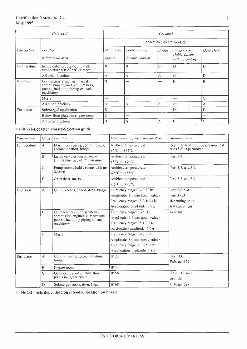
- From column 1 in Table 2.1, select main areas on board which are relevant for the equipment's intended field of application. From column 11, select actual location within rhc main areas selected from column 1. The actual locations are to be selected separately for each of the three parameters temperature, vibration and enclosure.
- Required location class for each of the three parameters, related to location, are then given by a cross reference between column I and TI.
Minimum required equipment specification for the location classes selected, as well as the corresponding tests in Section 3 which are to be carried out, may now be obtained from Table 2. 2.
Note: Tests listed in Table 2. 3 are to be carried out independent of location on board.
DET N ORSKE VERITAS
Certification Notes - No.2.4 May 1995
Columnll Column l
MAIN AREAS ON BOARD
Parameters Luca/ion Machinery Control room, Bridf{e !'ump rnom, Open Deck
within main area spaces Accommodation l!olds, Rooms with no heating
·1 ·emperature Insi<le cuhiclcs, desks, e!c. wi th temperature rise of 5°C or more
B B B D D
All other locations A A A c D
Vibration On machinery such as intt:rnal combustion engines, compressor.>,
ll - - B B
pumps, including piping on ~uch machinery
Ma~l:; - - - - c All other location~ A j\ A A J\
Enclosure Submerged application D - - D !)
Below lloor plates in engine room c - - - -All other locations B J\ J\ B c
Table 2-1-Location classes-Selection guide
Parameters Class l.ocation Minimum equipment specification lvlinimum tests
Temperature A Machinery spaces, control rooms, Ambient temperatures: Test 3.7. Not required if damp heat accommodation, bridge +5"C lo ·I 55°C test (3.8) is performed
13 Inside cuhiclcs, desk:;, etc. with Ambient temperatures: T~t 3.7. temperature rise of 5° C or more +5° C to +7U"C
c Pump rooms, holds, rooms with no Ambient temperatures: Test 3. 7. and 3. 9. hcaling -25°C to +55"C
D Open deck, masts Ambient temperatures: Test 3.7. and 3.9.
-25°C to +70°C
Vibration J\ On hulkhcads, beams, deck, bridge Frequency rnnge: 3-13.2 Hz. Test 3.6.2 or
Amplitude: 1,0 mm (peak value) Test 3.6.3
Prequency range: 13.2-100 1 l;o .. depemling upon
Acceleration amplitude: 0.7 g te~t equipment
H On machinery such as internal Frequency range: 3-25 H:t. availabk combustion engines, compressors. Amplitude: 1,6 mm (peak value) pumps, including piping on such machinery Frequency range: 25-100 111.
accelc.:ration amplitude: 4.0 g
c Mast:; Frequency range: 3-1 J.2 I !z.
Amplitude: 3.0 111111 (peak value)
Fr~qucncy rnngc: 13.2-50 llz.
Acc.:elcration amplitude: 2.1 g
Enclosure A Control rooms. accommodation. 11' 22 Te..~t ll ~C bridge Pub. m). 529
B Engine room 11' 44
c Open deck. masts. below lloor IP 56 T.:st 3.10. anJ plates in engine mom !CS! ll·:C
D ~uhmcrgcd application. bilges IP 68 l'uh. no. 529
Tnble 2-2 Tests depending on intended location on hoard.
Dt.T N ORSKE Vt-:RITAS
5
6
Tests Item
Pcrfomiance Test 3.3
Power Supply Test 3.4, 3.5
Damp heat 'fest 3.8
Inclination Test 3.11
Insulation Resistance Test 3.12
High Vo!tage ~fe!:;t 3.!3
EMC Test 3.14
Acceleration test 3.15
Additional Tests 3.16
Table 2-3 Tests independent on location on board
2.3 Testing Arrangement
2.3.l Where to Test
Environmental testing may be perfonned in:
a) DNV's laboratories at H0vik, Norway. b) Any independent laboratory recognised by DNV,
provided a detailed test programme approved by DNV is followed.
c) Any other recognised laboratory chosen by the manufacturer, provided a detailed test programme approved by DNV is used and the tests are witnessed by a DNV-surveyor.
2.3.2 Test Equipment
Measuring equipment is to be calibrated in accordance with procedures traceable to international or national standards, and is to be documented.
2.3.3 Test Specimen
In the case of series-manufactured products, the equipment under test is to be taken from the current production cycle. The choice of equipment under test is to be agreed with DNY.
If the equipment under test is a prototype, DNV reserves the right to carry out subsequent comparative tests on series-manufactured products.
2.3.4 Test Reports
The manufacturer is to submit the test results in triplicate for evaluation at DNY. The test reports, preferably in English, are to he signed by the responsible test personnel and the surveyor witnessing the tests, confirming that the tests have been carried out in accordance with the relevant test programme.
Evaluation of test results for tests exceeding the minimum required test levels, are to he based on the same approval criteria as for tests carried out in accordance with the minimum requirements.
Certification Notes - No.2.4 May 1995
3. Environmental Test Specification
3.1 General
3.1.l Relevant Test Programme
Prior to testing, a relevant and detailed test programme is to be prepared for each pa11icular test specimen. The test programme should be based on type of equipment, the manufacturer's equipment specification and the environmental tests required for the particular test specimen. The cnvir011mental tests imply tests which are independent of intended locatio11 on board as well as tests dependent on the location classes selected in accordance with 2.2 of this publication.
The relevant test programme is to specify how the performance tests are to be carried out, and specify what measurements/performance checks which are to be catTied out prior to, during, and after the various environmental tests.
All tests are normally to be carried out on the same unit. Dry heat test and vibration test arc to be can-ied out prior to the humidity test.
The relevant test programme is to be approved by DNV prior to commencement of the testing.
3.l.2 Normal Ambient Conditions
Basis: IEC publication 68-1
No1mal ambient conditions are defined as follows:
Temperature: TN= 20" C ± 2° C.Tempcraturcs between I 5°C and 35°C may be accepted provided selected temperature is kept constant within +2°C during all tests, and actual temperature is to be stated in the test report.
Relative humidity: RHN = 25% to 75%
Atmospheric 860-1060 mbar. pressure:
Radiation: Negligible
Vibration: Negligible
Power supply: Nomin_al value
3.2 Visual Ins1lection
The product is to be visually inspected for good workmanship, conformity with the manufacturer's drawings and specifications, an<l DNV Rules for Classification as applicable.
Appendix A. (Procedures for type approval) may be used as a guideline as far as applicable to the equipment under consideration. All relevant parts of the DNV Rules arc to be used as a basis when checking conformity with the DNV Rules.
DETNORSKE VERITAS
Certification Notes - No.2.4 May 1995
3.2.1 Procedure of visual inspections
The product is to be visually inspected ror good workmanship, conformity with the manufacturer's drawings and specifications, and DNV Rules as applicable.
3.2.2 Special Conditions
None
3.2.3 General Instructions for Performance of visual inspect ions
The visual inspection is carried out before commencement of testing and is to be repeated as found necessary after each stage of the test. The inspection is for detecting visible damage to the equipment being tested.
3.3 Performance Test
The functions (switching points, characteristic curves, self-monitoring etc.) are demonstrated.
3.3. 1 Tc.st Procedure
Basis: IEC publicatio11 92-504
Prior to performance testing the test specimen should reach its equilibrium state at nonna1 ambient conditions with no power on.
The orientation of the test specimen with regard to gravity force is to be as in normal service during the test.
The performance tests, sufficiently extensive to verify compliance with the manufacturer's equipment specifications and DNV Rules where applicable, arc to be carried out at normal ambient conditions according to the relevant test programme.
3.3.2 Special Test Conditions
None.
3.3.3 Genera l Instructions for Test Performance
The functions to be tested are to be performed in accordance with the requirements of DNV Rules for Classification and relevant standards, and the characteristic features of the equipment under test.
3.3.4 Test Result
The test is deemed to have been passed if the specified functions are demonstrated, the results fall within the specified tolerance limits and no damage to the equipment under test is detected.
3.4 Electrical Power Supply Failure Test
This test serves to demonstrate that on restoration of the power supply, no damage is caused to the equipment under test and no pe1manent or temporary malfunctions occur.
3.4.1 Test Procedure
Has is: !EC publication 92-504
- 3 interruptions within a 5-minute period; - 30 seconds pause between switching off and switching
back on.
3.4.2 General Instructions for Test Performance
None
3.4.3 Test Result
The test is deemed to have been passed if the specified functions are demonstrated, the results fall within the specified tolerance limits and no damage to the equipment under test is detected.
3.5 Power Supply Variation Tests
This test serves to demonstrate that in the event of power supply variations, no damage is caused to the equipment under test and no permanent or temporary malfunctions occur.
3.5. l Test Procedure
Basis: !EC publication 92-504
Prior to testing, the test specimen is to be supplied by nominal power and is to be in operation under normal load conditions, unless otherwise stated in the relevant test program. Before any power supply variations are applied, the test specimen shall be allowed to reach its equilibrium state.
Relevant stationary deviations are to be applied for the time necessary to establish a new equilibrium state and minimum for 15 minutes.
The relevant transient deviations are to be applied to the nominal voltage and frequency.
3.5.2 Test Levels
In the case of hydraulic/pneumatic components, the rated pressure in accordance with the equipment specification, is the basis for the tests.
D ETNORSKE VERITAS
7
8
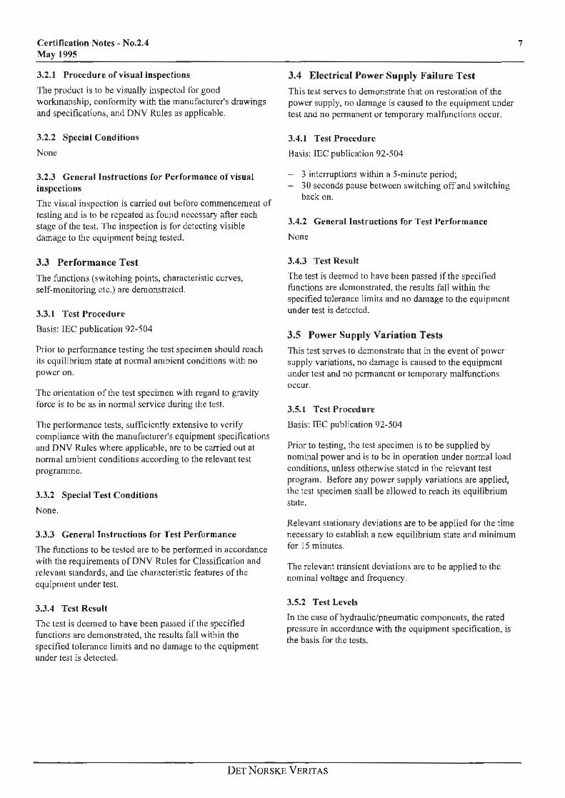
A) :Electrical Supply (alternating voltage)
Combination nn. VoltaRe deviation Frequenc.y deviation
I +10% -t 5 %
2 t-10 % -5 %
3 - 10% -5 %
4 - 10% +5%
5 0 0
6 0 0
B) Battery Power .Supply
No. Voltage deviation
7 +30 %
8 - 25 %
C) Pneumatic I Hydraulic Powl!r Supply
No Control pressure deviation
9 +20%
10 - 20 %
3.5.3 Test Result
The test is deemed to have been passed if the specified functions are demonstrated, the results fall within the specified tolerance limils and no damage to !he equipment under test is detected.
3.6 Vibration Tests
This test serves to demonstrate that under the influence of external initiated vibrations no damage is caused lo !he equipment under test and no pc1manent or temporary malfunctions occur. The Wide Band Random Test may be perfonned as an alternative to the Sweep sine Test for General Vibration Strain, Class A.
3.6.1 Definitions
Sweep sine Test: A v ibration test where the frequency of the sinusoidal excitation signal is varied continuously (swt:pt) ovt:r a frequt:ncy range.
Wide Band A test where the excitation signal is a Random Test: complex \.vave with a f1<it power spectral
dt:nslty versus fi't:quency and a Gaussian amplitude distrihution.
3.6.2 Sweep sine Test
3.6.2. J Test Procedure
Basis: JEC publication 68-2-6, Test Fe
The equipment under test is to be fastened to the test board by means of its own fastening devices. The equipment is to be mounted in its normal position, and in accordance with the manufacturer's instructions.
Certification Notes - No.2.4 May 1995
Voltage transient Frequeru.y transient
(/.5 s duration) (5 s duration)
0 0
0 ()
0 0
0 0
120 %. +10%
-20% -10%
If vibration dampers arc intended to be used during service, these are to be mounted during the test.
The test specimen is to be supplied by power and is to be in operation under normal load condition unless otherwise specified in the relevant test programme.
The orientation of the test specimen with respect to the gravity force , is to be as in nonnal service during the test.
The test specimen is to be vibrated in three mutually perpendicular planes unless otherwise stated in the relevant test programme. These planes arc to be chosen so that faull.s are most likely to be revealed.
The sweeping is to be continuous and logarithmic, and the sweep rate is to be maximum one octave per minute.
Resonance search is to be rnn at the actual test level specified in 3.6.2.4. No mechanical amplification factor greater than 10 will be accepted.
Endurance test is to be carried out for at least 90 minutes at all actual resonance frequencies (and at upper frequency if amplification factor is increasing with increasing frequency) where the amplification factor is greater than 2. Ir the resonance frequency varies during the test, the control equipment is to be adjusted accordingly. The test level is to be as in the sweep test. If no amplification factor higher than 2 is found, the endurance test is to be pcrfonned at the frequency of the highest one. If no resonance frequencies are found, the test is to be carried out at 30 Hz for Class A and H, and at l 0 H.7. for Class C.
3.6.2.2 Tolerances
Velocity or acceleration tolerances at the control point:± 10%, at the attachment point:± 15%.
Distortion of the acceleration wave fonn is not to exceed 25%.
Transverse motion is not to exceed 25% of the specified value.
Measurement of frequency for resonance detennination is to be made with a tolerance of± 0,5 H.7..
Frequency tolerances in other cases are to be ± 1 Hz.
DETNORSKE VERITAS
Certification Notes - No.2.4 May 1995
3.6.2.3 Performance Test
After the test, the test specimen is subjected to final performance test as specified in the relevant test programme.
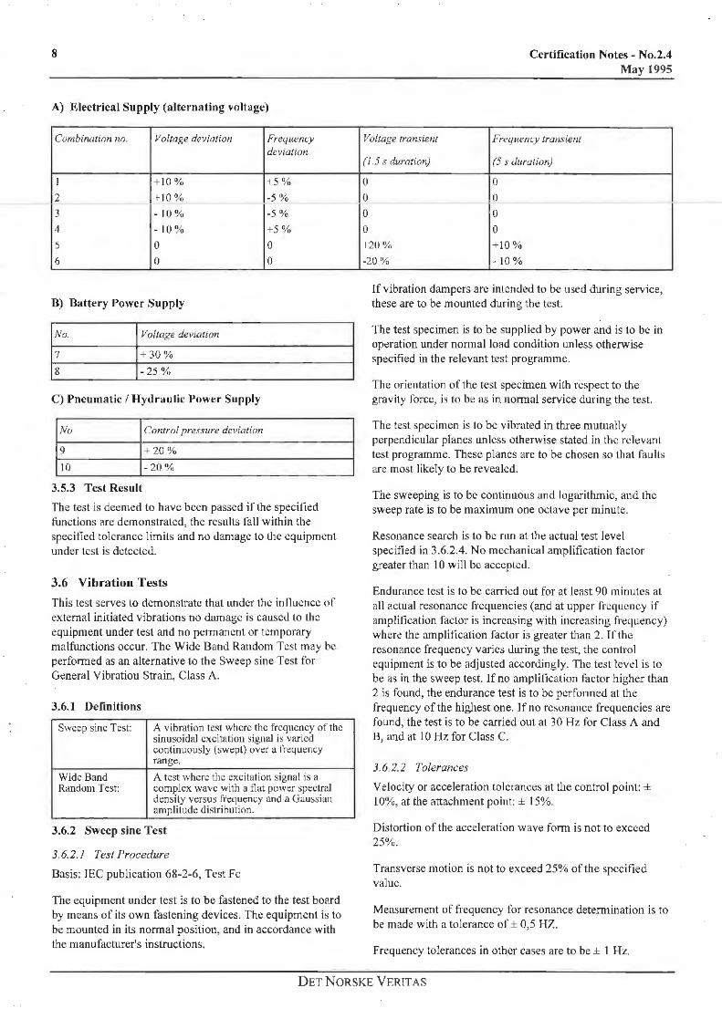
3.6.2.4 Test Levels
The test levels and frequency ranges for the three vibration classes are given in Fig. 3.1 below.
1mpMudom .. • 3.0 mm , Cl1os c (2, 1g)
_.ur I \,c; ,,.,, I ~don- . t,6mm ..... \ I l'T ·r 1·r ... I am11lludemu- • 1 ~omm \ .. Class 8 (4,0~) . . . • I~-' ---- - - - " ' .. --\ -1- ,_ _.._
- - " . - -~. 1- ,_ .
E' .§.
1- . \ \ \
, f-° ... Cl)
~ c. ~ O,t -
00, t t
-------------
~ ---
Clags A(0.7g)
10 Frequence (Hz]
Figure 3-1 Vibration Curves
-
\ . ...
·- "
f-
,__ P.
100 200
The levels are measured at the control point (the vibration table, unless otherwise specified in the relevant test programme). If necessary, a good quality band pass filter is to be used.
A) General Vibration Strain, Class A.
Displacement Acceleration
3 Hz to 13,2 llz 1,0 m111 (peak value) 13,2 llz to 100 Hz 0,7g
Sweep rate max. 1 octave/minute
B) High Vibration Strain, Class B.
Displacement Acceleration
3 Hz to 25 Hz 1,6 mm (peak value) 25 Hz to 100 1 Jz 4,0g
Sweep rate max. I octave/minute
C) Vibration Strain, Class C.
Displacement Acceleration
3 Hz to 13,2 Hz 3,0 mm (peak value)
13,2 Hz to 50 Hz 2,lg
Sweep rate max. 1 octave/minute
3.6.2.5 Test Result
The test is deemed to have been passed if the specified functions are demonstrated, the results fall within the specified tolerance limits and no damage to the equipment under test is detected.
3.6.3 Wide Band Random Test
3.6.3.1 Test Procedure
Basis: IEC publication 68-2-34, Test Fd.
The equipment under test is to be fastened to the test board by means of its own fastening devices. The equipment is to be mounted in its no1mal position, and in accordance with the manufacturer's instructions.
If vibration dampers are intended to be used during service, these are to be mounted during the test.
The test specimen is to be operating under normal load condition unless otherwise specified in the relevant test programme.
The orientation of the test specimen with respect to the gravity force, is to be as in normal service during the test.
The test specimen is to be vibrated in three mutually perpendicular planes unless otherwise stated in the relevant test programme. These planes are to be chosen so that faults are most likely to be revealed.
9
Resonance search is to be run at the actual test level , specified in 3.6 .2.4 for Class A. No mechanical amplificatfon factor greater than 10 will be accepted.
Endurance test is to be can-ied out for at least 2,5 hour in each of the three planes.
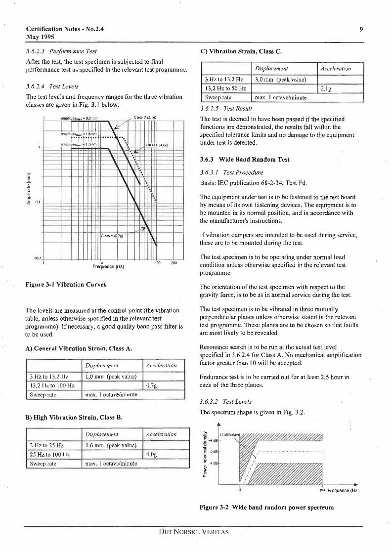
3.6.3.2 Test levels
The spectrum shape is given in Fig. 3.2 .
Z;·;;; :ij .... d8 i::>
Jg Od8 u QI a. "' ·4d8
j ...
100 Frequence (Hz
Figure 3-2 Wide band random power spectrum
DET N ORSKE VERlTAS
10
The total RMS values measured through a good quality band pass filter, are 1,0 g in the frequency range 3- 100 Hz.
The levels are referred to the control point (the vibration table, unless otl1erwise specified in the relevant test programme).
:J. 6. J. J 'J'ulerances
PSD: :.I: 4 dll with bandwidth-time-product of minimum 300 with frequi::ncy resolution of 11250 of maximum fri::qucncy.
RMSg: ± 1,5 dB.
3.6.3.4 Performance Tests
After the test, the test specimen is subjected to final perfo1mance test as specified in the relevant test programme.
3.6.3.5 Test Result
The test is deemed to have been passed if the specified functio11s are demonstrated, the results fall within the specified tolerance limits and no damage to the equipment under test is detected.
3.7 Dry Heat Test
3.7.1 General
This test serves to demonstrate that under the influence of dry heat, no damagt: is caused to the equipment under test and no pennancnt or temporary malfunctions occur.
3. 7.1.1 Chamber Temperature and Humidity Measurement
The chamber is to be so constructed that the specified conditions in the working space, can be maintained within the tolerances g iven. The conditions at any point of the working space, are to be unifonn and as similar as possible to those prevailing in the immediatt: vicinity of temperature and humidity sensing devices installed. These devices are to be located at such a distance from the test specim en, that the effect of dissipation is negligible.
3. 7. 1.2 Air Flow.
Forced convet.1ion in the chamber is to not be used when testing heat gent:rating specimen.
3.7.2 Test Procedure
Basis: !EC publication 68-2-2, Tests Bb and Bd.
3. 7.2. J Preconditioning
Test specimen is to be kept at nomrnl ambient condiLions for initial pcrfo1manct: testing, according to the relevant test programme.
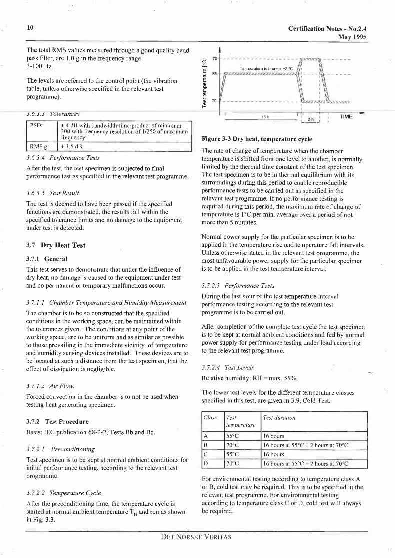
3. 7.2.2 Temperature Cycle
Alter the preconditioning time, the temperature cycle is sta1ted at normal ambient temperature TN and run as shown in Fig. 3.3.
Certification Notes - No.2.4 May 1995
Figure 3-3 Dry heat, temperature cycle
The rate of change of temperature when the chamber temperature is shined from one level to another, is nomially limited by the thermal time constant of the test specimen. The te:-it specimen is to be in thennal equilibrium with its surroundings during this period to enable reproducible performance tt:sts to be carried 011t as specified in the relevant test programme. If no perfonnance testing is required during this period, the maximum rate of change of temperature is I °C per min. average over a period of not more than 5 minutes.
Normal power supply for the particular specimen is Lo be applied in the temperature rise and temperature fall intervals. Unless oLhcrwise stated in the relevant test programme, the most unfavourdble power supply for the particular specimen is to be applied in the test temperature interval.
3. 7.2.3 Performance Tests
During the last hour oftl1c test temperature interval performance testing according to the relevant test programme is to be caffied out.
After completion of" thc complete test cycle the test specimen is to be kept at normal ambit:nt conditions and fed by normal power supply for perfonnance testing under load according to the relevant test programme.
3. 7.2.4 Test Levels
Relative humidity: RH = max. 55%.
The lower test levels for the different temperature classes specified in this test, are given in 3.9, Cold Test.
Class 1'e.~t Te.st duration il:mperature
A 55°C 16 hours
B 70°C 16 hOL1rs at 55°C + 2 hours at 70°C
c 55°C 16 hours
I) 1ouc 16 hours at 55°C + 2 hours at 70°C
For environmental testing according to temperature class A or 13, cold test may be re4uired. This is to be specified in the relevant test programme. For environmental testing according to temperature c lass C or D, cold test will always be required.
DET NORSKE VERITAS
Certification Notes - No.2.4 May 1995
3. 7.2.5 Tolerances
Temperature: ± 2° C.
Relative humidity: ± 10%
3.7.3 Test Result
The test is deemed to have been passed if the specified functions are demonstrated, the reslllts fall within the specified tolerance limits and no damage to the eqtLipment under test is detected.
3.8 Damp Heat Test
3.8.1 General
This test serves to demonstrate that under the influence of damp heat no damage is caused to the equipment under test and no pennanent or temporary malfunctions occur.
3. 8. J. l Cham her Temperature and Humidity Measurement
See 3.7. l.l
3.8.1.2 Air Flow
The air velocity across the humidity sensor is to be 1,5-2,0 mis.
3.8. J.3 Humidifying
Only distilled water or water filtered and passed through an ion-exchanger is to be used for humidifying, and for the wet bulb thennometcr (if used).
3.8.2 Test Procedure
Basis: IEC publication 68-2-30, Test Db
3. 8.2. l Preconditioning
Perfonnance tests are to be carried out at nonnal ambient conditions in accordance with the relevant test programme.
Insulation resistance test, where appropriate, is to be carried out in accordance with 3.12
Prior to exposure to high humidity, the test specimen is to reach its equilibrium state at nonnal ambient conditions with no power on.
3.8.2.2 Temperature and Humidity Cycle
After the preconditioning humidity and temperature cycling is to be carried out in accordance with Fig. 3.4.
11
Wb.2zaZ!23 'f£un.f' 11 ·c
_Gh __
----1 cycle = 24 hours
12~"'-h _ _ _
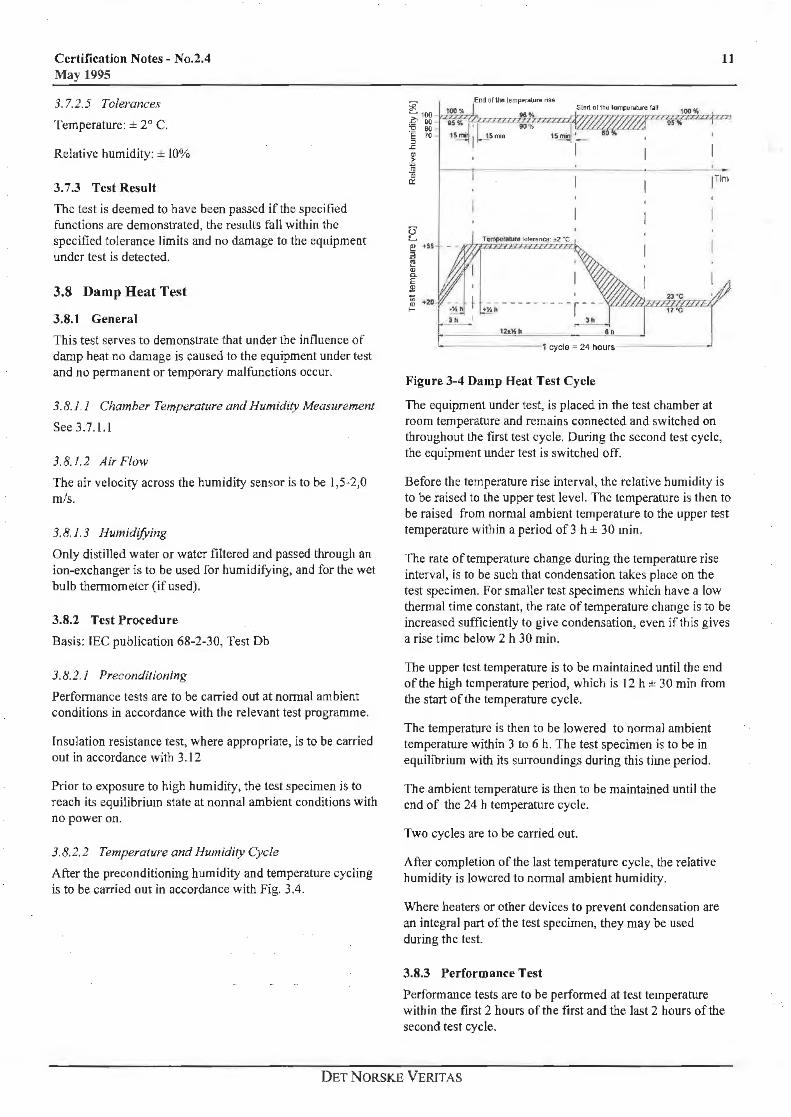
Figure 3-4 Damp Heat Test Cycle
The equipment under test, is placed in the test chamber at room temperature and remains connected and switched on throughout the first test cycle. During the second test cycle, the equipment under test is switched off.
Before the temperature rise interval, the relative humidity is to be raised to the upper test level. The temperature is then to be raised from normal ambient temperature to the upper test temperature within a period of 3 h ± 30 min.
The rate of temperature change during the temperature rise interval, is to be such that condensation takes place on the tes.t specimen. For smaller test specimens which have a low thennal time constant, the rate of temperature change is to be increased sufficiently to give condensation, even if this gives a rise time below 2 h 30 min.
The upper test temperature is to be maintained until the end of the high temperature period, which is 12 h ± 30 min from the start of the temperature cycle.
The temperature is then to be lowered to nonnal ambient temperature within 3 to 6 h. The test specimen is to be in equilibrium with its su1Toundings during this time period.
The ambient temperature is then to be maintained until the end of the 24 h temperature cycle.
Two cycles are to be carried out.
After completion of the last temperature cycle, the relative humidity is lowered to nonnal ambient humidity.
Where heaters or other devices to prevent condensation are an integral part of the test specimen, they may be used during the test.
3.8.3 Performance Test
Performance tests are to be performed at test temperature within the first 2 hours of the first and the last 2 hours of the second test cycle.
DET NORSKE VERIT AS
12
Within one hour at nonnal ambient humidity and temperature, the following tests are to be carried out:
- Perfonnance test in accordance with the relevant test programme.
- Insulation resistance test, where appropriate, according to 3.12.
J.8.4 Test Levels
See fig. 3.8.
3.8.5 Tolerances
Temperature: ± 2° C
Relative humidity: :1:3%
3.8.6 Test Result
The test is deemed to have been passed if the specified functions are demonstrated, results fall within the specified tolerance limits and no damage to the equipment under test is detected.
3.9 Cold Test
3.9.1 General
This test serves to demonstrate that under the influence of cold, no damage is caused to the equipment under test and no permanent or temporary malfunctions occur.
3.9. I. I Chamber Temperature and Humidity Measurement
Sec 3.7.1.J
3.9. l.2 Air Flow
Forced convection in the chamber is to not be used when Lesli11g heat generating specimen.
3.9.2 Test Procedure
Basis: IEC publication 68-2-1, Tests Ab and Ad.
3.9.2. J I'recnnditioninx
The test specimen is to be kept at normal ambient conditions for initial performance testing according to lhc relevant test programme.
Insulation resistance test, where appropriate, is to be carried out in accordance with 3.12.
Certification Notes - No.2.4 May 1995
3.9.2.2 Temperature Cycle
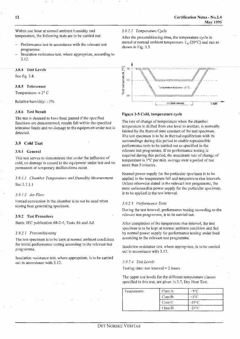
After the preconditioning time, the temperature cycle is started at normal ambient temperature TN (20°C) and run as shown in Fig. 3.5.
I Temperah.re lolerance :t2 ·c
~ " L _--_----.--[_ 2 h (teS1 lnleNal) J TI ME
l<'igure 3-S Cold, temperature cycle
The rate or change of temperature when the chamber temperature is shifted from one level to another, is nomrnlly limited by the thennal time constant of the test specimen. The lest specimen is to be in thermal equilibrium with its surroundings during this period to enable reproducible performance tests to be carried out as specified in the relevant test programme. If no performance testing is required during this period, lhe ma-ximum rate of change of temperature is I °C per min. average over a period of not more than 5 minutes.
Normal power supply for the particular specimen is to be applied in the temperature fall and temperature rise intervals. Unless otherwise stated in the releva.ut test programme, the most unfavourable power supply for the particular specimen, is to be applied in the test interval.
3. 9.2. 3 Performance Te.~ts
During the test interval, performance testing according to the relevant test programme, is to be can-ied out.
Afler completion or the temperature rise interval, the test specimen is to be kept at normal ambient condition and fed by nonnal power supply for performance testing under load according to the relevant test programme.
Insulation resistance test, where appropriate, is to be carried out in accordance with 3.12.
3. 9.2.4 Test Levels
Testing time: test interval= 2 hours
The upper lest levels for the different temperature classes specified in this test, are given in 3.7, Dry Heat Test.
Temperature: Class A: ·15°C
Class B: 15°C
Class C: .2s0 c Class D: -25°C
DET NORSKE VERIT AS
Certification Notes - No.2.4 May 1995
3. 9. 2. 5 T o/erances
Temperature: ± 2° C.
3. 9.3 Test Result
The test is deemed to have been passed if the specified functions are demonstrated, the values of' the insulation resistance measurement foll within the specified tolcrnncc limits and no damage to the equipment under test is detected.
3.10 Salt Mist Test
This test serves to demonstrate that under the influence of a saline atmosphere, no damage (corrosion) is caused to the components of the equipment under test and no functional affections occur.
3.10. I. I Sult Solution
The sail solution is to be made from NaCl analytical reagent quality and distilled water.
The solution is to be kept at the chamber temperature during the test.
The pll of the solution is to be between 6,5 and 7,2.
3.10.2 Test Procedure
Basis: IEC publication 68-2-52, Test Kb
Before commencing the test an insulation resistance measurement is to be taken in accordance with 3 .12 and a functional test is to be performed.
The test consists of 4 sprayings and 7 days storage in the damp chamber after each spraying.
On the 7th day of each storage period, functional tests are to be performed.
On completion of the test, a functional test is lo be perfo1med and an insulation resistance measurement to be taken in accordance with 3 .12. The condition of the equipment under test is to be evaluated (visual inspection) .
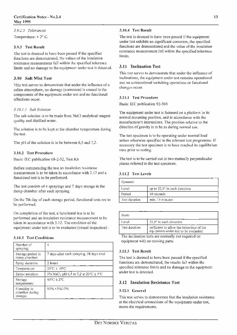
3.10.3 Test Conditions
Number of 4 spraying:
Storage period in 7 days afler each spraying, 28 days total damp chamber:
Spray duration: 2 hours
Temperature: 25°C ± 10°C
Saline solution : 5% NaCl, pH 6,5 to 7,2 at 20"C ± 2"C
Storage 40°C ± 2°C kmperature:
I lurnidity in 93%+3%/-2% chamber <luring storage:
3. J0.4 Test Result
The test is deemed to have been passed if the equipment under test exhibits no significant corrnsion, the specified functions are demonstrated and the value of the insulation resistance measurement fall within the specified tolerance limits.
3.11 Inclination Test
This test serves to demonstrate that under the influence of inclinations, the equipment under test remains operational and no unintentional switching operations or functional changes occur.
3.11.l Test Procedure
Basis: IEC publication 92-504
The equipment under test is fastened on a platform in its normal mounting position, and in accordance with the manufacturer's instructions. The position relative lo the direction of gravity is to be as during normal use.
13
The test specimen is to be operating under normal load unless otherwise specified in the relevant test programme. If necessary the test specimen is to have reached its equilibrium state prior to testing.
The test is to be carried out in two mutually perpendicular planes referred to the test specimen.
3.11.2 Test Levels
Dynamic
l,evel up to 22,5° in ea<.:h direction
Period JO seconds
Test duration min. 15 minutes
Static
l.evt:I 22,5" in each direction
Test duration sufficient to allow tht: behaviour oftht: equipment under test to bt: evaluatt:<l.
The inclination tests are normally not required on equipment with no moving parts.
3.11.3 Test Result
The test is deemed to have been passed if the specified functions arc demonstrated, the results fall within the specified tolerance limits and no damage to the equipment under test is detected.
3.12 Insulation Resistance Test
3.12. t General
This test serves to demonstrate that the insulation resistance at the electrical connections of the equipment under test, meets the requirements.
DETNORSKE VERITAS
14
The insulation resistance test comprises two tests:
- Test A which is an initial test. - Test B which is to be carried out within one hour after the
Damp Heat Test (3.8). Test B is also to be canied out within one hour after Cold Test (3.9), Salt Mist Test (3.10) or High Voltage Test (3.13) when these tests are required according to the relevant test p1og1a111111l:.
Test B is to demonstrate that the insulation resistance remains within the specified tolerance limits.
3.12.2 Test Procedure
Basis: IEC publication 92-504
3.12.2. l I'reconditionin}!,
Any filters installed between circuit and earth to avoid problems with EMJ, may be removed before the test. Prior to insulation test A, the test specimen should reach its equilibrium state at normal ambient condition with no power on.
3. I 2.2.2 Tests
The insulation resistance is to be measured between supply tel1llinals and earth.
Test voltage and minimum insulation resistance are given in table 3.1 below. Test A specifies minimum insulation resistance during initial test. Test B specifics minimum insulation within one hour after a humidity-, cold- or salt mist test.
Rated supply Test voltage /J.C. Minimum insulaliun voltage resistance
Test A Test B
Up to 65 V 2 x supply voltage minimum24V
IOMO. I MO.
Over 65 V 500V lOOMQ IOMO.
Table 3-1 Minimum insulation resistance.
3. 12.3 Test Results
The test is deemed to have been passed if the values arc not lower than those specified in the table.
3.13 High Voltage Test
This test serves to demonstrate that the dielectric characteristics at the electrical connections of the equipment under test, meet the requirements of the test standard.
3.13.1 Test Procedure
Basis: JEC publication 92-504
3. J 3. 1. J Preconditioning
Certification Notes - No.2.4 May 1995
Prior to the high voltage test, the test specimen is allowed to reach its equilibrium state at nomrnl ambient conditions with no power on.
3.13.1.2 Test Levels
Unless higher test voltage is specified by the equipment 1ipe1;iu1;oiliu11 fu1 li1e le~l :.ve1.:im~n. uie high vuiiage lest (where appropriate) is to be carried out at a frequency of 50 or 60 Hz with an A.C. test voltage according to the table 3.2 below.
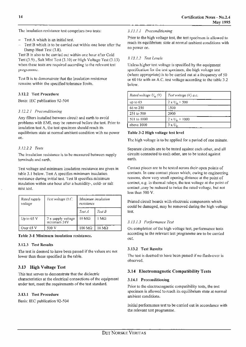
Rated voltage Un (ljl Te.~f voltage (V) a.c.
up lo 65 2 x u0 + soo 66 to 250 1500
251to500 2000
501 (O JO()() 2 x Un+ IOOO
above 1000 3 x Un
Table 3-2 High voltage test level
The high voltage is to be applied for a period of one minute.
Separate circuits are to be tested against each other, and all circuits connected to each other, are to be tested against earth.
Contact pieces are to be tested across their open points of contacts. In case contact pieces which, owing to engineering reasons, show very small opening distance at the point of contact, e.g. in thermal relays, the test voltage at the point of contact ,may be reduced to twice the rated voltage, but not less than 500 V.
Printed circuit boards with electronic components which could be damaged, may be removed during the high voltage test.
3.13.1.3 Performance Test
On completion of the high voltage test, performance tests according to the relevant test programme are to be carried out.
3.13.2 Test Results
The test is deemed to have been passed if no flash-over is observed.
3.14 Electromagnetic Compatibility Tests
3.14.1 Preconditioning
Prior to the electromagnetic compatibility tests, the test specimen is allowed to reach its equilibrium state at nonnal ambient conditions.
Initial performance test to be carried out in accordance with the relevant test programme.
DET NORSKE VERJTAS
Certification Notes - No.2.4 May 1995
3.14.2 Electrical Fast Transient/Burst Test
3.14.2. I Test Procedure
Basis: IEC Publication 1000-4-4
During the electrical fast transient/burst test, the test specimen is to be in operation under nonnal load and power supply, and to be connected to extemal wiring in accordance with the manufacturer's recommended procedure.
A fast transient signal is to be superimposed to each of the power supply lines (AC and DC) in tum, and to signal lines via a capacitive coupling clamp. The fast transient signal is to be in accordance with test levels specified below:
Test Levels
Pulse 5150 ns, 15ms burst in every 300 ms
Amplitude 2 kV, common mode, power lines
I kV, common mode, signal lines
Polarities ±
Duration 2 minutes per polarity
Repetition rate 5 kH:r.at I kV
2,5 kHz at 2 kV
Tolerances
Burst duration and period ±20%
Source impedance ±20%
Amplitude ±10%
3.14.2.2 Performance Test
Performance test is to be cruTied out in accordance with the relevant test programme.
3. 14. 2. 3 Test Results
The test is deemed to have passed if the test specimen is not subject to functional failure or malfunction.
Temporary degradation ofperfonnance which do not unduly affect the function of the test specimen may be accepted.
3.14.3 Electrical Slow Transient/Surge Test
3.14.3. I Test Procedure
Basis: IEC Publication 1000-4-5
During the electrical slow transient/surge test, the test specimen is to be in operation under normal load and power supply, and be connected to external wiring in accordance with the manufacturer's recommended procedure.
A slow transient signal is to be superimposed to each of the power supply lines (AC and DC), both in differential mode and common mode. The slow transient signal to be in accordance with test levels specified below:
Test levels
Pulse 1,2/50 µs voltage surge
8/20 µs current surge
Amplitude I kV, differential mode
2 kV, common mode
Polarities ±
Number of pulses 5 per polarity
Repetition rate I per minute
Tolerances
Amplitude, open/short circuit ±10%
3.14.3.2 Performance Test
Performance test is to be carried out in accordance with the relevant test programme.
3.14. 3. 3 Test Results
15
The test is deemed to have passed if the test specimen is not subject to functional failure or malfunction.
Temporary degradation of performance which do not unduly affect the function of the test specimen may be accepted.
3.14.4 Conducted High Frequency Test
3.14.4. I Test Procedure
Basis: IEC Publication I 000-4-6 (Draft)
Dw'ing the conducted high frequency test, the test specimen is to be in operation under nonnal load and power supply, and be connected to external wiring in accordance with the manufacturer's recommended procedure.
A high frequency signal is to be superimposed to each of the power supply lines (AC and DC) in common mode. The high frequency signal is to be in accordance with test levels specified below:
Test Levels
Frequency range 150 kHz - 80 MHz
Amplitude 3VRMS
Amplitude 80% at I kHz modulation
Max. sweep rate 0,005 octave/s (1,5 x 10·3 decade/s)
Tolerances
Amplitude ±10%
Jf continuous sweep cannot be performed, the test may be carried out at discrete frequencies. The frequency steps are to be maximum l % of the frequency.
3.14.4.2 Performance Test
Performance test is to be carried out in accordance with the relevant test programme.
DET NORSKE VERITAS
16
3.14. 4. 3 Test Results
The test is deemed to have passed ir the 1.cst specimen is not subject to functional failure or malfunction.
3.14.5 Radiated Susceptibility Test
This test serves to demonstrate that under the influence of electromagnetic fields no damage is caused to the test specimen and no permanent or temporary malfunctions occur.
3. 14. 5. I Test Procedure
Basis: lEC publication 1000-4-3
The test specimen is to be placed in a shielded enclosure with its most sensitive side facing the radiating antenna. The distance between the test specimen and the antenna is preferably to be 3 metres (minimum 1 metre). If doubt exists regarding the most sensitive side, all six faces may, if this is considered necessary, be presented to the antenna.
The test specimen is to be insulated to prevent metallic contact between housing and the shielded enclosure. However, grounding or the test specimen's housing or case is to be ca1Tied out in accordance with the manufacturer's installation procedure.
Unless otherwise stated in the relevant test programme, the test specimen is to be in its housing with all covers and access panels in place. ff the test specimen is designed to be mounted in panels, rack or cabinet, equivalent protection may be provided.
During the radiation test, the test specimen is to be in operation under normal load and power supply, and be connected to external wiring in accordance with the manufacturer's recommended procedure.
Tf the manufaclurer does not specify extcmal wiring, unshielded twisted-pair wiring shall be used for a length equal to one metre from the point of connection to the test specimen.
The test specimen is to be exposed to an electromagnetic field in accordance with test levels specified below.
Test Levels
rn:quc::ncy range:: ~O MHz to 1 GHz
Electric field strength 10 Vim
Amplitude 80%al I kllz modulation
Max. ~wec::p rate 0,005 octavc/s (I ,5x 10·3 decade/s)
'/'olerances
Electric field strength -0/+6 dB
If continuous sweep can not be perfonned, the test may be carried out at discrete frequencies. The frequency steps are to be maximum 1% of the frequency.
3.14.5.2 Performance Test
Certification Notes - No.2.4 May 1995
Perfonnance test during the radiation test, is to be carried out in accordance with the relevant test programme.
3.14.5.3 Test Result
The test is deemed to have been passed ifthe test specimen is not subject to functional failure or malfunction.
3.14.6 Electrostatic Discharge Test
3. 14. 6.1 Test Procedure
Basis: TEC publication 1000-4-2
The electrostatic discharge test is to be carried out using an electrostatic discharge generator with typical cl1aracteristics in accordance with test levels specified below.
The test specimen is to be placed on an eruth reference plane made out of a metallic sheet, which shall project beyond the test specimen at least 0, 1 m on all sides. The minimum size of the reference plane is to be 1 m2 and the test specimen is to be isolated from it by an insulating support about 0, 1 m thick. The earth reference plane is to be connected to the protective conductor of the earth system.
The distance belween the test specimen and the walls of the laboratory and any other metallic structure, is to be minimum l m.
The earth cable orthe electrostatic discharge generator, is to be connected to the earth reference plane.
Connection of the test specimen to the earth system is to be in accordance with the manufacturer's specification. No additional earth connections are to be provided.
During the discharge test, the test specimen is to be ICd by normal power supply and is to be in operation as specified in the relevant test programme.
The static electricity discharges shall be applied only to such points and surfaces of the test specimen which are nonnally accessible to the operator. A minimum often spots arc to be selected.
Contact discharges arc to be applied to conductive surfaces and coupling planes. Air discharges are to be applied to insulating surfaces.
Ten discharges shall be applied at each preselected spot.
DF.T NORSKE VERITAS
Certification Notes~ No.2.4 May 1995
'fest Levels
Output voltage Air: 8 kV
Contact: 6 kV
Polarities ±
Tolet·ances
Energy storage capacitor .L 10%
Discharge resistor 1: 10%
Output voltage ±5%
3.14.6.2 Performance test
After the elcclrostatic discharge test, performance test is to be carried out in accordance with the relcvanl test programme.
3. 14.6.3 '/'est Result
The test is <kerned to have been passed if the equipment under test is not subject to functional failure or malfunction.
Temporary degradation ofperfonnanec which do not unduly affect the function of the equipment under test, may be accepted.
3.15 Acceleration Test
3. 15.l Gene1·al
The acceleration is to be as caused by the ship's movements in waves.
3.15.2 Test Procedure
The test specimen is to be mounted on a platfonn through its normal points of attachment, if necessary by means of a fixture. The position relative to the direction of gravity, is to be as during normal use.
The test specimen is to be operating under normal load unless otherwise specified in the relevant test programme . rr necessary, the test specimen is to have reached its equilibrium state prior to testing.
The test is to be carried out in three mutually perpendicular planes referred to the test specimen.
3.15.3 Test Levels
Peak accelerations: L0,6 g for vessels of length exceeding 90 m, ± 1 g for smaller vessels.
Duration: 5-10 sec.
3.J 5.4 Performance Tests
To be specified in the relevant test programme.
3.16 Additional Tests
Additional tests may be specified in the rc!~vant lest programmes. Such tests may comprise:
3.16.l
3.16.2
3.16.3
3.16.4
3.16.5
3.16.6
3.16.7
3.16.8
3.16.9
3.16.10
3.16.11
3.16.12
3.16.13
3.16.14
3.16.15
3.16.16
3.16.17
Flame-retardant test.
lee test.
High temperature test.
Temperature shock test.
Low pressure test.
High pressure test.
Mechanical shock test.
Wind-pressure test.
Sealing test.
Soldering test.
Mould growth test.
Storage test.
Working medium quality test for pneumatic and hydraulic equipment.
Radiation test.
Explosion safety or intrinsic safety test for electrical equipment.
Acoustic noise test.
Air pollution, sensitivity test.
DETNORSKE VERITAS
17
18
4. Appendix A. Procedures for type approval.
4.1 Scope
This appendix gives information on the procedure to be followed to obtain DNV Type Approval for instrumentation and automation equipment.
The following documents describe the type approval system inDNV:
- Certification Notes No. 1.1 "Det Norske Veritas' certification services - General description"; and
- Certification Notes No. 1.2 "Det Norske Veritas conformity certification services Type approval".
Products granted Type Approval on the basis of DNY Rules for Classification, will be accepted for use on board vessels and mobile offshore units classed with DNY, provided they are installed in accordance with the Rules.
Type approval of instrumentation and automation components or systems is nonnally not compulsory, but is an alternative to the case-by-case approval granted for each specific vessel.
4.2 Design Assessment
Type approval of instrumentation and automation equipment implies that the product has been evaluated for conformity with the manufacturer's drawings and specifications, and DNV Rules as applicable.
The assessment includes environmental tcsling to verify Lhc operational parameters stated by the manufacturer.
4.3 Type Approval Certificate
When a product is type approved, DNV will issue a Type Approval Certificate which specifics field of application/special operational limitations of the product in question.
Type Approval Certificate is valid for 2-4 years, depending on type of equipment. Application for renewal is to be made in due course before the expiry date of the certificate. DNV is to be kept informed on changes in design, choice of parts or materials. Such changes, dissatisfactory experience or amendments of applied Rules, Codes, Regulations or Standards may at any time lead to withdrawal of the Type Approval.
4.4 Register of Type Approved Products
Type approved equipment is I isted in «REGISTER Ol' TYPE APPROVF.O PRODUCTS: INSTRUMENTATION /\ND
AUTOMATION No. 7». These publication, which are up-dated at regular intervals, are distributed to all manufacturers listed and are available to operators, yards, designers and other interested parties.
Certification Notes - No.2.4 May 1995
4.5 Application for Type Approval
The manufacturer, or his representative, may apply for type approval of a certain product. The manufacturer is responsible to maintain the quality of a type approved product during the validity time of the type approval certificate. Therefore, application for type approval of a product is nomrnlly to be submitted by the manufacturer. ,Ai.pp!icnticn subm~ttcd by !he munufucturcr's icprc:.;cr;tativc, is to be accompanied by a statement from the manufacturer confirming that the representative may act on behalf of him. The application is to be sent to the local DNV survey station, which will forward the application to DNV office responsible for Type Approval. Application forms and assistance with the application may be obtained at the local DNV survey station. The type approval certificate will be issued in the name of the manufacturer.
When applying for type approval, the manufacturer is to specify type number which completely identifies the product according to drawings/equipment specification. All optional features for which type approval is requested, arc to be listed, either by separate type numbers or by suffixes to the equipment's basic type number.
The manufacturer is also to specify the location classes for which he requests the product type approved. Please see «How to Select Location Classes», Section 2.2.2.
4.6 Type Approval Fees
Type approval fees will be charged according to the current scale of fees. The fees include the costs related to cvalualion of design and administration (issuance of certificates, printing and distribution of lists, keeping of records, etc.)
The costs for laboratory tests, running of computer programmes, witnessing of tests, travelling and subsistence are not included in the scale of fees and will be charged in addition.
4.7 Design Assessment and Data for Instrumentation and Automation Equipment
The information given below, is only given as guidance. for details, see relevant rule requirements.
4.7.l Design Details
To the extent applicable, the equipment under consideration will be checked for the following:
4. 7.1. I Construct ion
. I Materials
• Explosive materials and materials which may develop toxic gases, are generally not to be used.
• Covers, tennination boards, printed circuits card, constructive clements and other parts which may contribute to spreading fire, are to be of flame-retardant material.
DET NORSKE VERIT AS
Certification Notes - No.2.4 May 1995
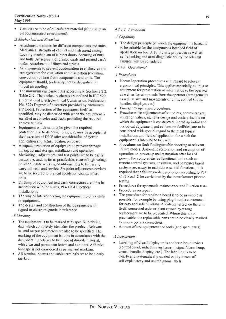
• Gaskets are to be of oil-resistant material (if in use in an oil contaminated environment).
.2 Mechanical and Electricol
• Attachment methods for different components and units. Mechanical strength of cabinet and instrument casing. Locking mechanism of cabinet doors. Securing of nuts and bolts. Attachment of printed cards and printed card's racks. Attachment of filters and strums.
• Arrangements to prevent condensation in enclosures and arrangements for ventilation and dissipation (radiation, convection) of heat from components and units. The equipment should, preferably, not be dependent on forced air cooling.
• The minimum enclosure class according to Section 2.2.2, Table 2. 2. The enclosure classes are defined in !EC 529 (fntemational Electrotechnical Commission, Publication No. 529) Degrees of protection provided by enclosures (fP Code). Protection of the equipment itscu: as specified, may be dispensed with when the equipment is installed in consoles and desks providing the required enclosure class.
• Equipment which can not be given the required protection due to its design principle, may be accepted at the discretion of DNV after consideration of system application and actual location on board.
• Adequate protection of equipment to prevent damage during normal storage, installation and operation.
• Measuring-, adjustment- and test points arc to be easily accessible, and, as far as practicable, clear of high voltage or other unsafe working conditions. It is to be easy to carry out tests and service. Set point adjustments devices are to be secured to prevent accidental change of set point.
• Earthing of equipment and earth connectors are to be in accordance with the Rules, 1,1.4 Ch.4 Electrical Installations.
• The way of interconnecting the equipment to other units or equipment.
• The design and construction of the equipment with regard to electromagnetic interference.
.3 Markinx
• The equipment is to be marked with specific ordering data which completely identifies the product. Relevant in- and output parameters are also to be specified. The marking of the equ ipment is to be in accordance with the data sheet. Labels are to be made of durable material, with clear and permanent letters and numbers. Adhesive foil/tape is not considered as permanent marking.
• All terminal boards and cable terminals arc to be clearly marked.
19
4. 7. 1. 2 Functional
. 1 Capability
• The design principle on which the equipment is based, is to be suitable for the equipment's intended field of application on board. Fnil to safe properties as well as self-checking and auto-diagnostic ability for relevant failures, will be considered.
4. 7. 1.3 Operational
. 1 Procedures
• Nonna! operation procedures with regard to relevant ergonomical principles. This applies especially to units or equipment for presentation of information to the operator as well as for commands from the operator (arrangements as well as size and movements of units, control knobs, handles, displays, etc.).
• Emergency operation procedures. • Procedures for adjustments of set points, control ranges,
limitation values, etc. The design and basic principle on which the equipment is constructed, including initial and periodical adjustment and calibration facilities, are to be considered with special regard to the most typical installations and field of application for which the equipment is intended to be used.
• Procedures on fault finding/trouble shooting at relevant failure modes. Automatic restoration and resumption of operation on power-up and restoration afler loss of power. For comprehensive functional units such as remote control systems, or similar, an<l computer based systems necessary to maintain essential functions, it is required that a failure mode description according to Pt.4 Ch.5 Sec. I C be carried out by the manufacturer prior to testing.
• Procedures for systematic maintenance and function tests. • Procedures on repair. • The procedure for repair on board is to be as simple as
possible, for example by using plug in units constructed for easy and sufc handling. Accidental effect on the unit itself. connected units or plant caused by wrong replacement are to be prevented. Where this is not practicable, the replaceable parts are to be clearly marked to ensure correct connection.
• Amount of test equipment and tools (and spare parts}.
. 2 lnslructions
• Labelling of vi~ual display units and user input devices (control panel, indicating instrument. signal/alarm lamp, control handle. display, etc.). Tile labelling is to be clearly and systematically carried out by means of self-explanatory and unambiguous labels.
DF.:T NORSKE VCRITAS
20
.3 instruction Manuals
The instruction manuals are to include sufficient infonnation on the following:
• Equipment or system description. For complex equipment this description is to also contain a block diagram of the equipment in which all portions arc represented by annotated, interconnected boxes and other agreed simple figures.
• Functional description such as operation modes (normal/emergency), start/restart (with necessary adjustments), signal routing, timing, etc.
• Installation of equipment or system. • Fault symptoms and fault finding/trouble shooting
instmcti on s. • Description of relevant repair procedure. • Description of maintenance and functional test routines. • Spare part list, service network (including address, phone
No., cable address, etc.) of the vendor. • Safety measures regarding mounting/dismantling, power
connections, fault finding, maintenance, handling, etc.
4.7.2 Production
4. 7.2. I Production Control
• During the validity time or the type approval certificate it is the manufacturer's responsibility to ensure that the product is manufactured in accordance with the equipment specification on which the type approval was based.
Certification Notes - No.2.4 May 1995
4.7.3 Documents for Submission
4. 7.3. I General
• Together with the application, lhc manufacturer is to submit drawings, equipment specification and data sheets in accordance with 7.3.2 below. Documentation received by DNV will be treated confidentially, and will not be available to any third parts.
• All documentation is to be marked with either drawing/reference number, date of printing or similar which identifies the documentation as such. Marking of tJ1c documentation by means of the equipment's type number only is not considered as sufficient marking of the documentation.
• The manufacturer is to a lso submit a proposed «Relevant Test Programme» according to section 3.1 of this publication. This test programme is to be approved by DNV prior to commencement of t11c testing.
• All documentation is to be submitted in triplicate, of which one copy will be returned in stamped order.
• Document-.; are to be submitted in accordance with the Certification Notes No. 1.2 "Det Norske Veritas conformity certification services Type approval" 4. l.3. and DNV Rules for Classification, Part 4 Chapter 5, "Instrumentation and Automation" Section 1 C.
• • The lists contained in the above requiremenls are by way
of example. If necessary, further documents may be required.
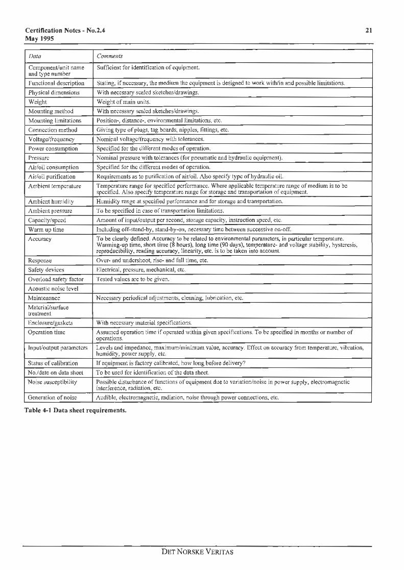
4. 7.3.2 Data Sheet
• The data sheet is to include all technical data which is necessary for a plant designer. The list of data sheet requirements, given in Table A I below, is of general nature, and the manufacturers will have to evaluate which items are applicable to their equipment.
DET NORSKE V ER IT AS
Certification Notes - No.2.4 May 1995
J)ata Comments
Component/unit name and type number
Sufficient for identification of equipment.
functional description Slating, if necessary, the medium the equipment i:; designed to work with/in and possible limitations.
Physical dimensions With necessary scaled sketches/drawings.
Weight Weight of main units.
Mounting method With necessary scaled sketches/drawings.
Mounting limitations Position-, distance-, environmental limitations, etc.
Connection method Giving type of plugs, lag boards, nipples, li11 ings, ere.
Voltage/frequency Nominal voltage/frequency with tolerances.
Power consumption Specified for the different modes of operation.
Pressure Nominal pressure with tolerances (for pneumatic and hydraulic equipment).
Air/oil consumption Specified for the ditkrenl modes of operation.
/\ir/oil purification Requirements as to purification of air/oil. Also specify type of hydraulic oil.
Ambient temperature Temperature range for specified performance. Where applicable temperature range of medium is to be specified. Also specify temperature nmge for storage and transportation of equipment.
Ambient humidity Humidity range at specified performance and for storage and transportation.
Ambient pressure To be specified in case of transportation limitations.
Capacity/speed Amount of input/output per second, storage capacity, instruction speed, etc.
Warm up time Including off-stand-by, stand-by-on, necessary time between successive on-off.
Accuracy To be clearly defined. Accuracy to be related lo environmenta l parameters, in particular temperature. Warming-up time, short ti.me (8 hours), long time (90 days), temperature- and voltage stability, hysteresis, reproducibility, reading accuracy, lineariry, etc. is lo be taken into account.
Response Over- and undershoot, rise- and fall time, etc.
Safety devices nlectrical, pressure, mechanical, etc.
Overload safety factor Tested values are to be given.
Acoustic noise level
Maintenance Necessary periodical adjustments, cleaning, lubrication, etc.
Matcri al/surface treatment
Enclosure/gaskets With necessary material specifications.
Operation time Assumed operation time if operated within given specifications. To be specified in months or number of operations.
Input/output parameters Levels and impedance, maximum/minimum value, accuracy. Effect on accuracy from temperature, vibration, humidity, power supply, etc.
Status of calibration If equipment is factory calibrated, how long before delivery?
No./date on data sheet To be used for identification of the data sheet.
Noise suscept ibility Possible disturbance of functions of equipment due to variat ion/noise in power supply, electromagnetic interference, radiation, etc.
Generation of noise Audible, e lectromagnetic, radii1tion, noise through power connections, etc.
Table 4~1 Data sheet requirements.
DET NORSKE VERITAS
21


•.