Embed Size (px)
Citation preview
Environmentally Assisted Fatigue Cracking in Pressurized Water
Reactors Lindsay O’Brien
12/17/2012
I. Abstract
Fatigue crack growth data for steels in Pressurized Water Reactors environments are
currently prescribed using crack reference data in air from Section XI of the ASME Boiler and
Pressure Vessel code [Ref. 1]. Laboratory studies have discerned that Light Water Reactor
environments can contribute significantly to fatigue crack growth rates, and research has been
undertaken in order to better predict component lifetime. Currently, conservative approximations
are applied to the ASME air curves in order to account for environmental effects on fatigue crack
growth, but this approach lacks understanding as to the enhancement, and in some instances,
retardation, of crack growth rates due to environment, as well as the mechanisms behind the
effects. The coolant (light water, in Pressurized Water Reactors) flow rate and temperature, as
well as the cyclic fatigue load quantities and the specimen material composition, all contribute to
fatigue crack growth rate. Further research into the mechanisms behind the effects of the
aforementioned quantities is needed to accurately predict the lifetime of Pressurized Water
Reactor components.
II. Introduction
The nuclear industrial and naval fleet in the United States, since the introduction of
nuclear reactions for power production, is limited in design almost entirely from material
performance. Parameters such as peak fuel temperature, heat transfer, performance under
transients, and neutron flux, to name a few, are all tied directly to the response of materials in
and out of the core, and material selection has been a growing field within the nuclear power
community in order to design safer systems with economic output. The most recent nuclear
power accident, Fukushima Daiichi, illustrates the wide spectrum of material considerations that
are involved, which includes load bearing effects, radiation damage, and temperature damage.
Although the accident can be assessed through operational contributions of system components,
the most rudimentary issue is the behavior of the material –the perfection of plant materials
would thus result in a avoidance of the accident. In an effort to continuously improve on the
safety of nuclear power, the understanding of material behavior in such an aggressive
environment is essential.
Environmental degradation is a substantial contributing factor in the lifetime of a Light
Water Reactor (LWR). As discussed by Seifert et al. [Ref. 2], in Pressurized Water Reactors
(PWR), the current method for assessing environmental corrosion fatigue cracking in austenitic
stainless steels is to use reference fatigue crack growth curves from Section XI of the ASME
Boiler and Pressure Vessel Code, which are measured in air, and then prescribe conservative
factors to account for crack growth enhancement in elevated temperature water. This method is a
result of a lack of data and knowledge for fatigue crack initiation and growth, and environmental
effects under PWR conditions were thought to be trivial in comparison to Boiling Water Reactor
(BWR) conditions, which are far more oxidizing. In an effort to provide accurate predictions of
fatigue crack growth failure, recent research has revealed an environmental effect on cracking,
even in PWR’s, but retardation of these environmental effects under certain conditions as well
[Ref. 2]. A lack of failure of stainless steel components gives rise to possibility of extending the
lifetime (and therefore reducing the large degree of conservatism) of these parts, but to do so will
require filling in the lack of knowledge for environmentally assisted fatigue crack growth in
stainless steels in PWR environments.
III. Background
PWR Environment:
PWR environments contain several important features that can play a role in fatigue
crack growth, and also differ notably from BWR environments. PWR coolant and moderator
temperature ranges from about 530º F to 600ºF. Plants operate with a hydrogen overpressure, and
O2 is kept at a minimum, and as such, PWR environments are often considered much less
oxidizing than BWR environments. Nomura et al. detailed the inability to use BWR curves that
were prescribed by the Japan Society of Mechanical Engineers in 2003, due to the marked
differences in water chemistry, as well as the lack of consideration for temperature effects in the
reference curves [Ref. 3]. Figure 1 illustrates the oxygen and hydrogen concentrations within a
PWR test environment, and this is indicative of the chemistry used amongst test plans for the
references cited in this paper. Unless otherwise stated, tests were performed at 288 º C [550 º F].
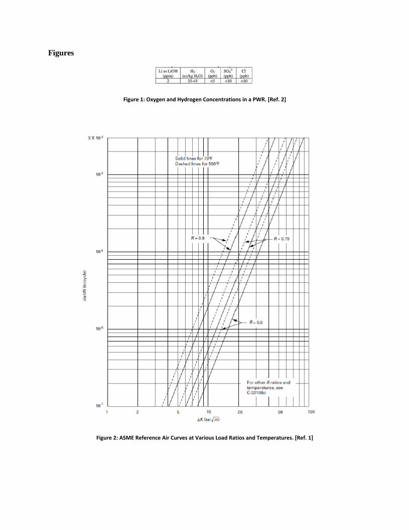
Air Curve Data:
Figure 2, Reference 1 shows the reference fatigue crack growth curves in air for
austenitic stainless steels. Crack growth rate curves are presented for multiple R ratios for room
temperature (70ºF) and a high temperature (550º F) indicative of PWR environments. Crack
growth curves are plotted using crack growth in inches per cycle as a function of the cyclic stress
intensity factor, ΔK.
IV. Environmental Effects on Fatigue Cracking
Relation to Air Curve Data:
In general, there are two notable trends that arise from the evaluation of fatigue crack
growth data in a PWR environment. The first of note is enhancement of crack growth rates above
the air curve, which can demonstrate rates up to 80 times that of the air curve data, especially if
testing is performed under long rise time loading cycles [Ref 4]. Wire, Evans and Mills have
reported acceleration up to 20 times the air rates [Ref 5]. On the contrary, some data has shown a
retardation of enhanced rates to those more indicative of the air curves, which arise from water
flow rate and temperature, as well as material composition of the steel, and these retardation
effects will be detailed in other sections of this report.
Effect of Crack Size:
In the determination of mechanisms that account for the environmental acceleration and
retardation, attention on the crack size of interest is necessary. Due to the reduction of the
effective load on a crack caused from crack closure, short cracks may have larger crack growth
rates than larger cracks. Wire and Mills have detailed the use of controls in air in order to gather
a full range of data without discrimination to crack size [Ref. 6]. Figure 3 shows that for a wide
range of crack sizes, data correlates well, as well as demonstrating that enhancement of
environmental rates over the air curve decreases at higher air rates. The lack of variation in long
and short cracks suggests that chemical enhancement for short cracks is not prevalent.
Effect of Water Flow Rate:
In order for environmentally assisted cracking (EAC) to occur, a critical concentration of
sulfides must be present at the crack tip [Ref. 7]. This sulfur is a product of the dissolution of
MnS stringers in high temperature water that exist in low-alloy steels. These sulfides can be
removed via various types of mass transport, and therefore flow into and out of the crack tip can
contribute to the amount of mitigation of EAC. James et al. investigated the effect of water flow
rate using 78.9 L/min, 27.0 L/min, and 8.69 L/min, with Reynolds numbers of 643000, 221000,
and 72200, respectively, and results are presented in Figure 4. The highest flow rate shows a
complete mitigation of EAC, while the intermediate flow rate also shows a success in mitigating
EAC to well below the EAC line. The lowest flow rate demonstrates a lack of EAC mitigation.
Water flow rate, therefore, may be one of the largest contributors to the presence (or lack
thereof) of EAC, and could explain the general lack of environmentally assisted fatigue cracking
over a reactor’s lifetime, especially if conservative correction factors to account for EAC are
applied. The typical flow rate of coolant water in a PWR is almost 2x10⁴ kg/s, which will benefit
low-alloy steel components in terms of EAC. Loss of flow, though, in a transient such as a loss-
of-flow accident, may contribute to a prevalence of EAC.
James et. al., in a second report, [Ref. 8] also studied the effect of water flow rate on low-
alloy steel that is overlaid with corrosion resistant cladding, in order to study the flow pattern
changes, as well as galvanic effects that could impact transport of sulfides out from the crack tip.
Flow velocities of 1.69 and 4.74 m/s were used, corresponding to the intermediate and high
velocities used in Ref. 7. Unlike previous results, the high flow rate did not mitigate EAC with as
much success as before, and effects of the high flow were not seen until the very end of the test.
Computational Fluid Dynamics (CFD) modeling demonstrated hindrance of flow to the crack tip
region, due to cladding, which further implies that mass transport at the crack tip is successful at
mitigating EAC.
In austenitic stainless steel, Tice et. al [Ref. 9] reported that the effect of flow rate is
similar to that of low-alloy stainless steels, but disagrees that the environmental enhancement is
due to sulfides, and rather some other soluble species. Due to the lower crack growth rates of
annealed stainless steel in oxygenated high temperature water, in which sulfides remain at the
crack tip due to the electrochemical potential gradient, Tice suggests that sulfides are not the
culprit. Furthermore, current research has suggested that a high sulfur content, such as that used
in the low-alloy steel cited in Reference 7, may in fact contribute to retardation of environmental
enhancement, as discussed further discussed in Section V of this report. Data presented in
Reference 8 also suggests that the mechanism that is responsible for a flow temperature threshold
of rise time also generates a flow rate threshold of rise time as well, as it was reported that lower
rise times are needed at high flow, high temperature water than at low flow, high temperature
water.
Effect of Water Temperature:
Wire et al. [Ref. 5] performed fatigue tests at 288º C and 243º C in order to measure the
effects of both rise time and temperature. Figure 5 depicts the results of those tests, shown with
the air curve data. Low rise times, below 50 seconds, show an obvious dependence on
temperature, in such that the lower temperature yields a lower crack growth rate, though it
should be noted that the lower temperature rates are still accelerated above the air data. At higher
rise times, though, the difference in temperatures appears to not contribute to crack growth rate
retardation. Although the lower temperature did not appear to change between 50 and 500
second rise times, the high temperature environment demonstrated retardation at the highest rise
time. This trend suggests that there may be a mechanism, related to the rise time of the test, that
is more prevalent under higher temperatures. Wire et al., in Reference 6, have suggested
hydrogen embrittlement as the cause for accelerated cracking in high temperature environments,
but also acknowledges that stress ratio and rise times are of interest in the low oxygen
environment of the PWR.
In addition to the above research regarding temperature effects, Tice et. al. [Ref. 9]
demonstrated that while environmentally assisted fatigue cracking is retarded for long rise times
at high temperatures (300 º C), lower load ratios, on the order of 0.3, require longer rise times in
order to exhibit the retardation effect. This possible threshold behavior is much like the one
discussed for flow rate in the previous section.
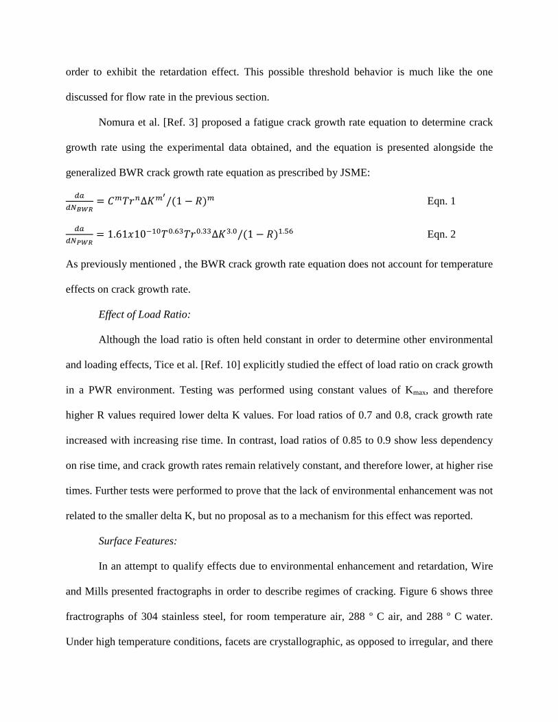
Nomura et al. [Ref. 3] proposed a fatigue crack growth rate equation to determine crack
growth rate using the experimental data obtained, and the equation is presented alongside the
generalized BWR crack growth rate equation as prescribed by JSME:
Eqn. 1
Eqn. 2
As previously mentioned , the BWR crack growth rate equation does not account for temperature
effects on crack growth rate.
Effect of Load Ratio:
Although the load ratio is often held constant in order to determine other environmental
and loading effects, Tice et al. [Ref. 10] explicitly studied the effect of load ratio on crack growth
in a PWR environment. Testing was performed using constant values of Kmax, and therefore
higher R values required lower delta K values. For load ratios of 0.7 and 0.8, crack growth rate
increased with increasing rise time. In contrast, load ratios of 0.85 to 0.9 show less dependency
on rise time, and crack growth rates remain relatively constant, and therefore lower, at higher rise
times. Further tests were performed to prove that the lack of environmental enhancement was not
related to the smaller delta K, but no proposal as to a mechanism for this effect was reported.
Surface Features:
In an attempt to qualify effects due to environmental enhancement and retardation, Wire
and Mills presented fractographs in order to describe regimes of cracking. Figure 6 shows three
fractrographs of 304 stainless steel, for room temperature air, 288 º C air, and 288 º C water.
Under high temperature conditions, facets are crystallographic, as opposed to irregular, and there
are clear river patterns on the specimen face. The river patterns are even more apparent in high
temperature water, and are observed for all crack growth rates. Furthermore, for the high
temperature water conditions, crack paths in specific areas deviate from the overall crack path,
which occurs due to regions of susceptibility, and these regions contribute to the enhanced rates
observed under this environment. Lastly, the appearance of sharp facets mark the effect of the
hydrogen embrittlement mechanism.
V. Further Research
Effect of Sulfur Content:
Recent research in environmentally effected fatigue crack growth behavior, as discussed
by Platts et al. [Ref. 4], has centered around material compositional effects, with emphasis on the
sulfur content of the stainless steel. Data has shown that intermediate sulfur content, above 0.02
weight%, shows retardation when compared to low sulfur heats of less than 0.01 weight%, a
phenomenon that appears in contrast to previously held beliefs. Figure 7 represents an example
of the data that has been presented with regards to high and low sulfur content, where Heat B
contained the high sulfur content. Both heats have the same crack growth behavior in air, but
Heat B, while demonstrating environmental enhancement under low rise times, demonstrated
retardation in rates under a longer rise time of 600s, shown in Stage 3 of the data. The crack
growth rates for this loading pattern, in the high sulfur heat, begin to approach the crack growth
data in air for this material. Further research has shown that retardation will occur under high
temperatures and high flow rates, and suggestions for this retardation have included the
possibility of crack tip blunting, due to the creep, or oxide closure at the crack tip. Research into
the effect of sulfur at the crack tip is currently being performed at MIT.
VI. Conclusion
Although current and past research has acknowledged the need to asses environmental
fatigue cracking in PWR environments, and data has been presented in order to quantify the
environmental effect, there is still a large knowledge gap as the mechanisms behind the data.
In order to take advantage of loading conditions, water flow rates, and material
considerations that can retard crack growth rates, especially within the strict regime of the
nuclear power industry, equipment lifetime predictions must be well documented. The most
promising methods to approach this problem involve the use of advanced
microcharacterization techniques, such as atom probe tomography, to decipher the
environment and behavior of the crack tip. Successful characterization of the mechanisms
that propagate the effects discussed in this paper could lead to the optimization of
components in a nuclear reactor, as well as an increase in time between inspection periods.
Figures
Figure 1: Oxygen and Hydrogen Concentrations in a PWR. [Ref. 2]
Figure 2: ASME Reference Air Curves at Various Load Ratios and Temperatures. [Ref. 1]
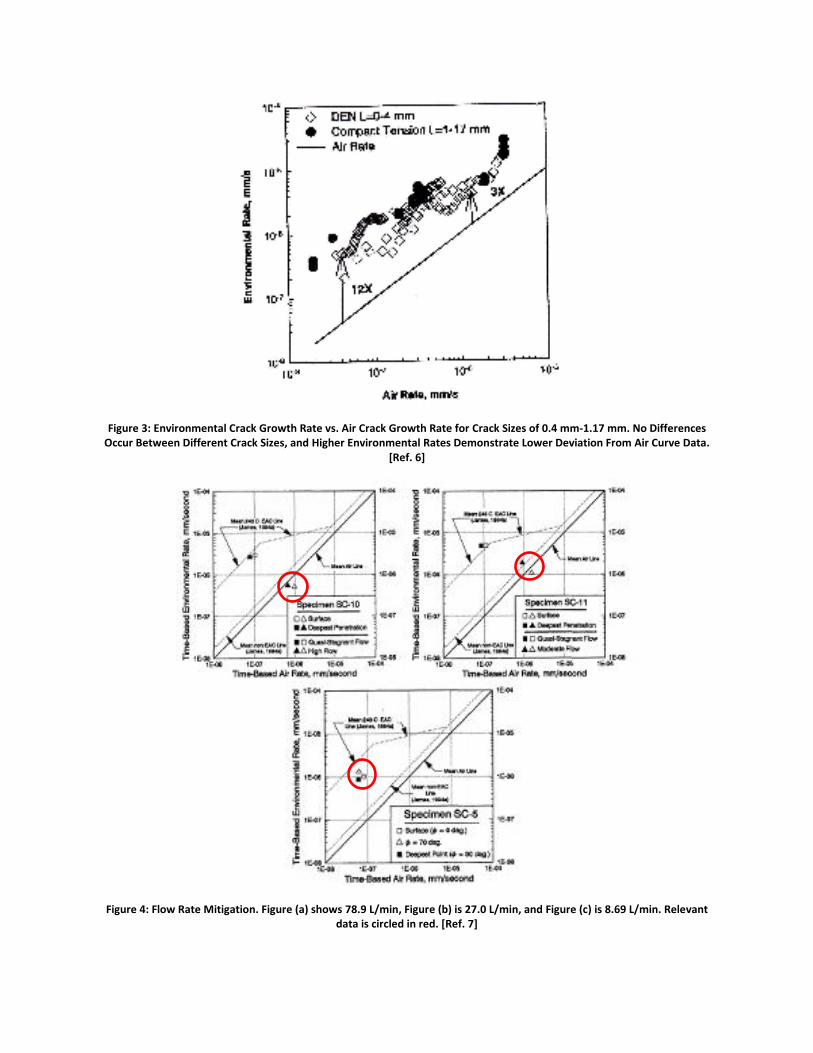
Figure 3: Environmental Crack Growth Rate vs. Air Crack Growth Rate for Crack Sizes of 0.4 mm-1.17 mm. No Differences Occur Between Different Crack Sizes, and Higher Environmental Rates Demonstrate Lower Deviation From Air Curve Data.
[Ref. 6]
Figure 4: Flow Rate Mitigation. Figure (a) shows 78.9 L/min, Figure (b) is 27.0 L/min, and Figure (c) is 8.69 L/min. Relevant data is circled in red. [Ref. 7]
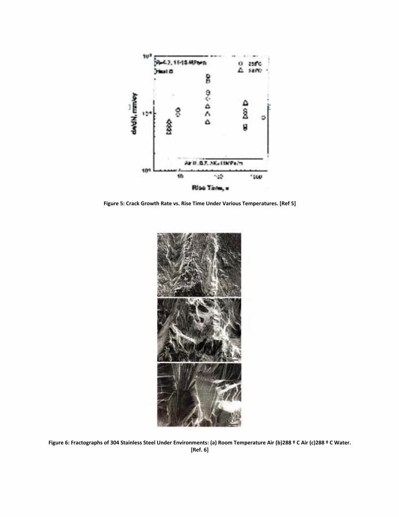
Figure 5: Crack Growth Rate vs. Rise Time Under Various Temperatures. [Ref 5]
Figure 6: Fractographs of 304 Stainless Steel Under Environments: (a) Room Temperature Air (b)288 º C Air (c)288 º C Water. [Ref. 6]
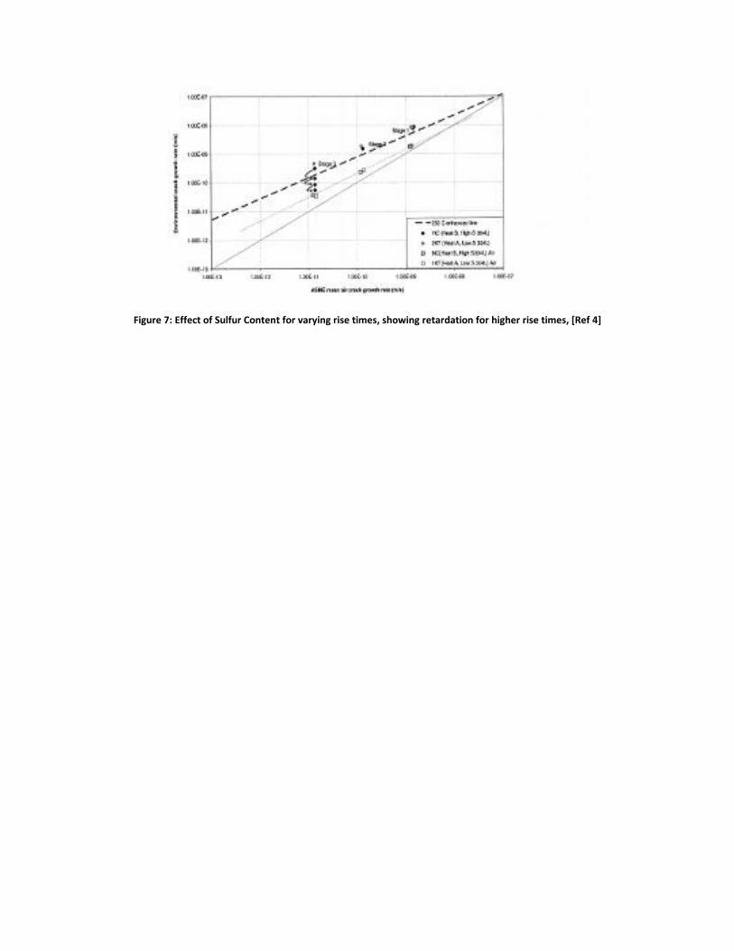
Figure 7: Effect of Sulfur Content for varying rise times, showing retardation for higher rise times, [Ref 4]
VII. References
1. American Society of Mechanical Engineers (2010). Rules for Inservice Inspection of Nuclear
Power Plant Components. Boiler and Pressure Vessel Codes, Section XI.
2. Seifert, H., Ritter, S., & Leber, H. (2012). Corrosion Fatigue Crack Growth Behavior of Austenitic
Stainless Steels Under Light Water Reactor Conditions. Corrosion Science, 61-75.
3. Nomura, Y., Tsutsumi, K., Kanasaki, H., & Chigusa, N. (2004). Fatigue Crack Growth Curve for
Austenitic Stainless Steels in PWR Environment. Pressure Vessel and Piping Codes and
Standards, 63-70.
4. Platts, N., Tice, D., Mottershead, K., McIntyre, L., & Scenini, F. (2012). Effects of Material
Composition on Corrosion Fatigue Crack Growth of Austenitic Stainless Steels in High
Temperature Water. In J. Busby, G. Ilevbare, & P. L. Andresen (Ed.), 15th International
Conference on Environmental Degradation of Materials in Nuclear Power Systems-Water
Reactors. Hoboken, NJ: John Wiley & Sons, Inc.
5. Wire, G., Evans, W. M., & Mills, W. J. (2004). Fatigue Crack Propagation Tests on 304 Stainless
Steel in High Temperature Water-Accelerated Cracking Rates and Transition to Lower Rates.
Pressure Vessel and Piping Codes and Standards, 71-81.
6. Wire, G. L., & Mills, W. J. (2004). Fatigue Crack Propagation Rates for Notched 304 Stainless
Steel Specimens in Elevated Temperature Water. Journal of Pressure Vessels, ASME, 318-326.
7. James, L., Lee, H., & Wire, G. (1997). The Effect of Water Flow Rate Upon the Environmentally
Assisted Cracking Response of a Low-Alloy Steel: Experimental Results Plus Modeling. Pressure
Vessel Technology, 83-90.
8. James, L., Lee, H., Wire, G., Novak, S., & Cullen, W. (1997). Corrosion Fatigue Crack Growth in
Clad Low-Alloy Steels-Part II: Water Flow Rate Effects in High Sulfur Plate Steel. Pressure Vessel
Technology, ASME, 255-263.
9. Tice, D., Platts, N., Rigby, K., & Stairmand, J. (2007). Influence of Temperature and Flow Rate on
the Corrosion Fatigue Crack Growth of Austenitic Stainless Steel in a PWR Primary Coolant
10. Tice, D., Platts, N., Rigby, K., Stairmand, J., & Swan, D. (2005). Influence of PWR Primary Coolant
Environment on Corrosion Fatigue Crack Growth of Austenitic Stainless Steels. Pressure Vessels
and Piping Division Conference (pp. 193-205). Denver, Colorado: ASME.