Embed Size (px)
Citation preview
EP 225 Waves, Optics, and FieldsWebsite: http://physics.usask.ca/~hirose/ep225/contains
• Course outline• Laboratory instruction• Notes• Past exams• Animation
Instructor: Akira Hirose Office Physics [email protected]: 966 6414
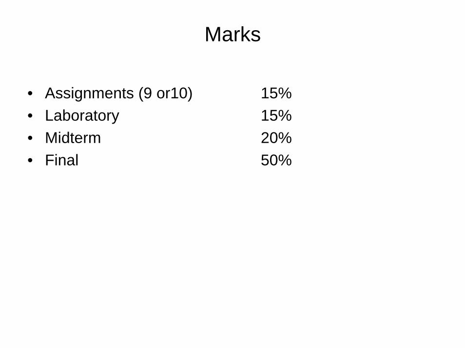
Marks
• Assignments (9 or10) 15%• Laboratory 15%• Midterm 20%• Final 50%

LaboratoryBrian Zulkoskey, Lab Instructor, Room 115 Physics, ph. 6439 [email protected]
LABS — START OF CLASSES
Students should be advised that labs for EP 225 will begin Monday, January 7.For these introductory sessions only, students will meet in the rooms listed below at the indicated times:
MON 7 JAN 1:30 p.m. L2A & B RM 126 PHYSICS WED 9 JAN 1:30 p.m. L4A & B RM 129 PHYSICS
• Students should bring a copy of "A Laboratory Manual for Engineering Physics 225.3, REVISED 1997". These are available at the Book Store.
• If a student misses the lab period for which he/she is scheduled, he/she should see Brian Zulkoskey in Room 115 Physics as soon as possible.
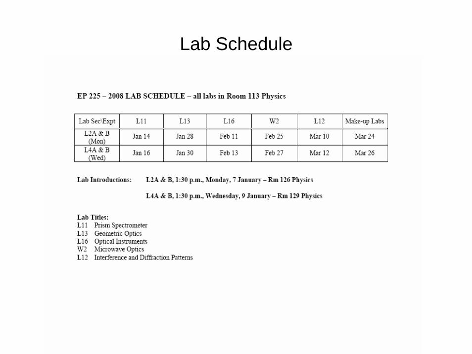
Lab Schedule
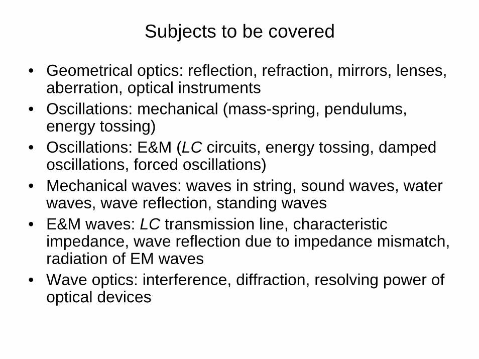
Subjects to be covered
• Geometrical optics: reflection, refraction, mirrors, lenses, aberration, optical instruments
• Oscillations: mechanical (mass-spring, pendulums, energy tossing)
• Oscillations: E&M (LC circuits, energy tossing, damped oscillations, forced oscillations)
• Mechanical waves: waves in string, sound waves, water waves, wave reflection, standing waves
• E&M waves: LC transmission line, characteristic impedance, wave reflection due to impedance mismatch, radiation of EM waves
• Wave optics: interference, diffraction, resolving power of optical devices
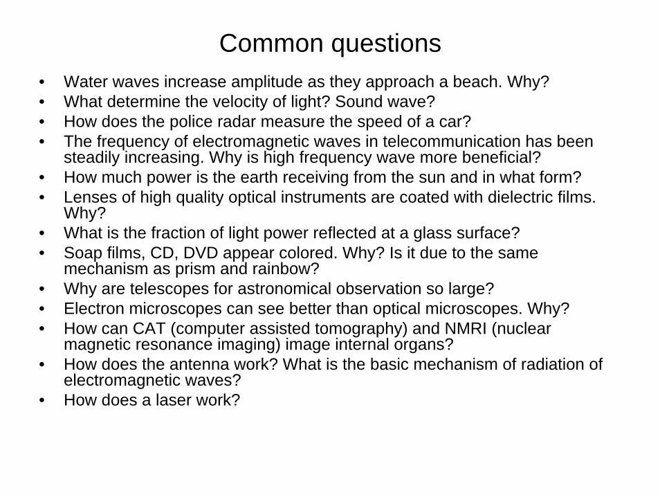
Common questions• Water waves increase amplitude as they approach a beach. Why?• What determine the velocity of light? Sound wave? • How does the police radar measure the speed of a car? • The frequency of electromagnetic waves in telecommunication has been
steadily increasing. Why is high frequency wave more beneficial?• How much power is the earth receiving from the sun and in what form? • Lenses of high quality optical instruments are coated with dielectric films.
Why? • What is the fraction of light power reflected at a glass surface? • Soap films, CD, DVD appear colored. Why? Is it due to the same
mechanism as prism and rainbow? • Why are telescopes for astronomical observation so large?• Electron microscopes can see better than optical microscopes. Why? • How can CAT (computer assisted tomography) and NMRI (nuclear
magnetic resonance imaging) image internal organs? • How does the antenna work? What is the basic mechanism of radiation of
electromagnetic waves? • How does a laser work?
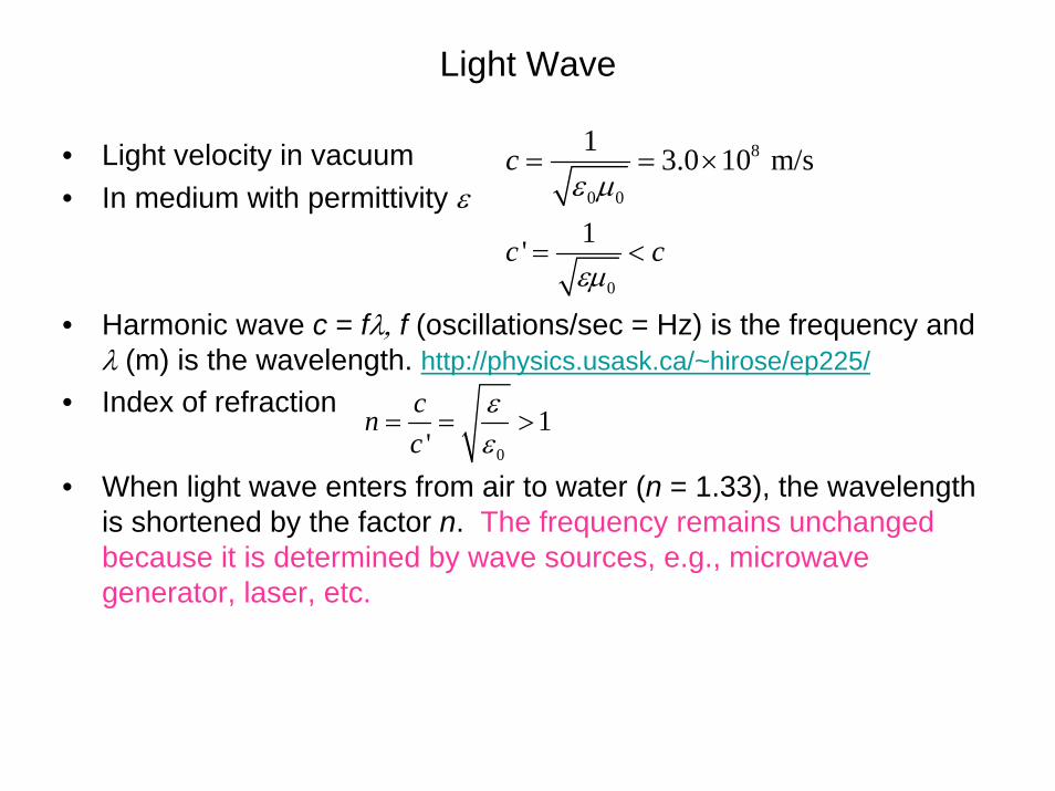
Light Wave
• Light velocity in vacuum• In medium with permittivity ε
• Harmonic wave c = fλ, f (oscillations/sec = Hz) is the frequency and λ (m) is the wavelength. http://physics.usask.ca/~hirose/ep225/
• Index of refraction
• When light wave enters from air to water (n = 1.33), the wavelength is shortened by the factor n. The frequency remains unchanged because it is determined by wave sources, e.g., microwave generator, laser, etc.
8
0 0
1 3.0 10 m/scε μ
= = ×
0
1'c cεμ
= <
0
1'
cnc
εε
= = >
Efforts to find c
• Roemer (Danish astronomer) observed change in the rotation period of the moon Io revolving around Jupiter. Based on Roemer’s data, Huygens deduced
• Bradley (British astronomer) found a fairly accurate estimate of
by aberration effect, shift in the angular location of distant star by
• Fizeau made the first laboratory measurement of the speed of light using rotating toothed wheel.
82.3 10 m/sc ×
82.8 10 m/sc ×
4/ where is the earth velocity 3 10 m/s.v c vθΔ ×
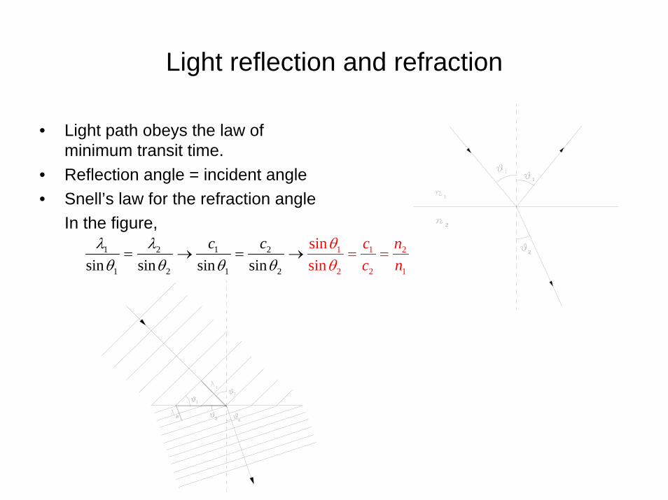
Light reflection and refraction
• Light path obeys the law of minimum transit time.
• Reflection angle = incident angle• Snell’s law for the refraction angle
In the figure, 1 2 1 2
1 2 1 2
1 1 2
2 2 1sin sin sin ssinsinin
c nc
c cn
θθ
λ λθ θ θ θ
= == → = →
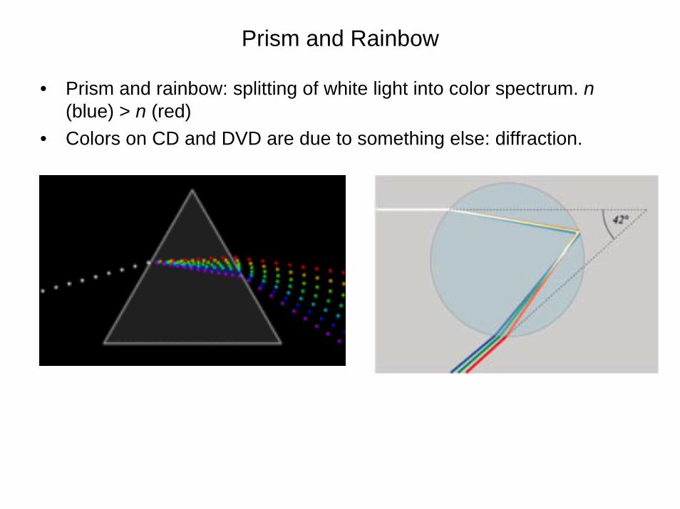
Prism and Rainbow
• Prism and rainbow: splitting of white light into color spectrum. n(blue) > n (red)
• Colors on CD and DVD are due to something else: diffraction.
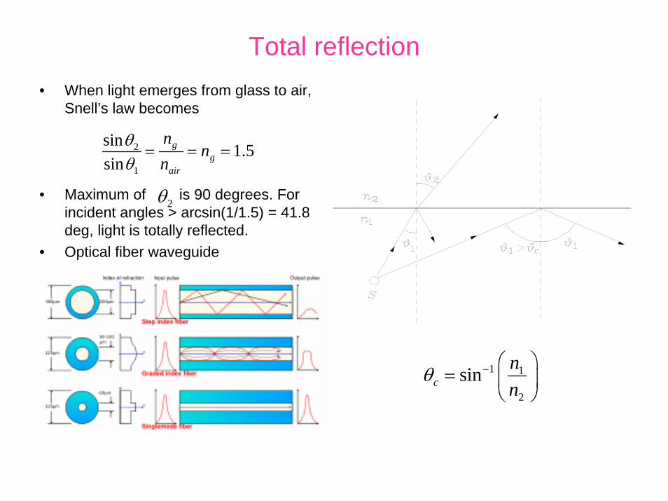
Total reflection• When light emerges from glass to air,
Snell’s law becomes
• Maximum of is 90 degrees. For incident angles > arcsin(1/1.5) = 41.8 deg, light is totally reflected.
• Optical fiber waveguide
2θ
2
1
sin 1.5sin
gg
air
nn
nθθ
= = =
2θ
1 1
2
sincnn
θ − ⎛ ⎞= ⎜ ⎟
⎝ ⎠

Total reflection
Example: Find the range of incident angle for total reflection at the vertical surface.
( )
13 2
11
1sin 50.3 , 90 50.3 39.71.3
sin 1.3sin 39.7 56.1
θ θ
θ
−
−
⎛ ⎞> = = − =⎜ ⎟⎝ ⎠
< =

Spherical Mirrors
• Assume small aperture h << R• Reflection is symmetric about the
radial line • Place an object at axial position o
(not zero) and find the image location i.
Example: Concave mirror with f = 10 cm. Object at 15 cm, real image at 30 cm. Magnification is m=-i/o=-2 (inverted image).
Example: Virtual object distance (negative o)
1 1 2 1 , focal length
, 2 ,2h h h
o i R
fo i R f
α θ γ θ γ β α β γ
+ = = =
+ = + = → + =
+ =
Mirrors (cont)
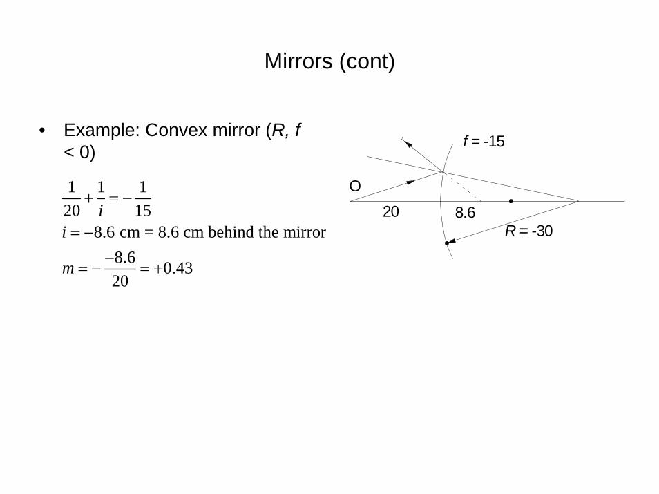
• Example: Convex mirror (R, f< 0)
1 1 120 15
8.6 cm = 8.6 cm behind the mirror8.6 0.4320
ii
m
+ = −
= −−
= − = +
f = -15
R = -30
O20 8.6
Spherical and Parabolic Mirror
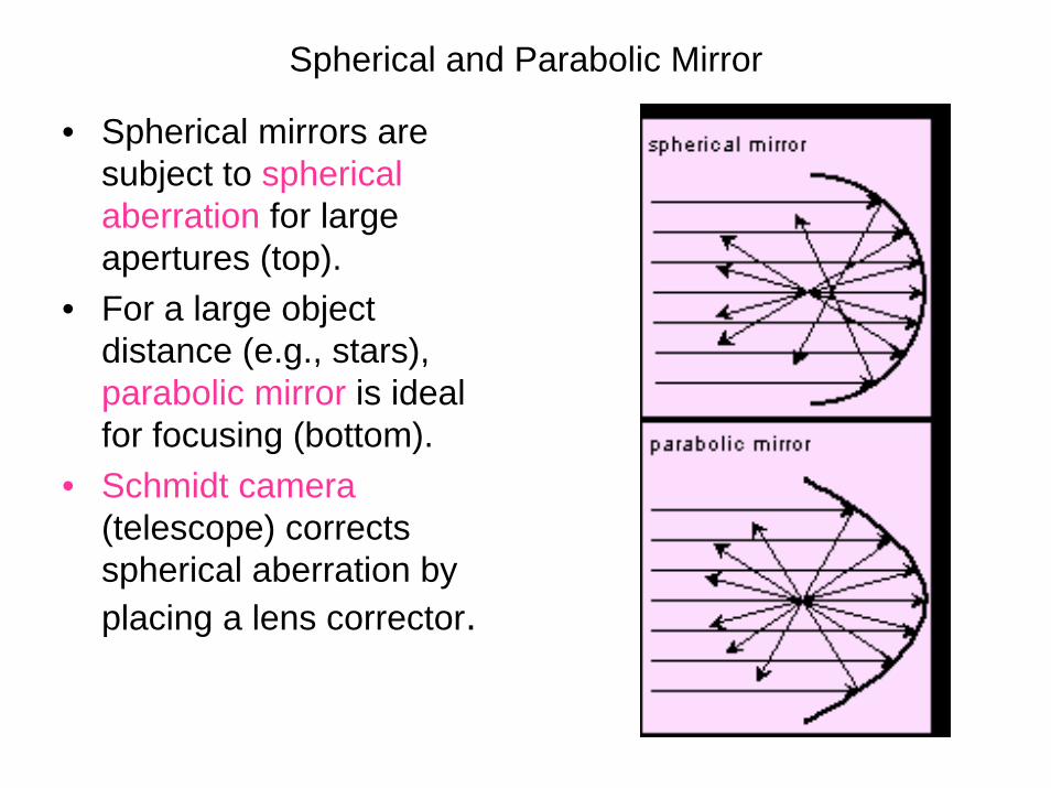
• Spherical mirrors are subject to spherical aberration for large apertures (top).
• For a large object distance (e.g., stars), parabolic mirror is ideal for focusing (bottom).
• Schmidt camera(telescope) corrects spherical aberration by placing a lens corrector.
Sign Convention, Magnification
• Mirrori, o > 0 real object and real image distance in front of the mirroro, i < 0 virtual object and image distance behind the mirrorR > 0, f = R/2 > 0 concave mirrorR < 0, f = R/2 < 0 convex mirror
• Lateral (or angular) magnificationm = -i/o, m > 0 erect image, m < 0 inverted
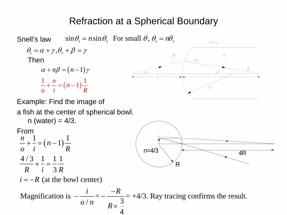
Refraction at a Spherical Boundary
Snell’s law
Then
Example: Find the image of a fish at the center of spherical bowl.
n (water) = 4/3.From
sin sini rnθ θ=
,i rθ α γ θ β γ= + + =
sin sin For small , i r i rn nθ θ θ θ θ= =
( )1n nα β γ+ = −
( )1 11n no i R
+ = −
( )1 11
4 / 3 1 1 13
(at the bowl center)
n no i R
R i Ri R
i R
+ = −
+ =
= −−Magnification is = = +4/3. Ray tracing confirms the result.3/
4o n R
− −×
R
4Rn=4/3
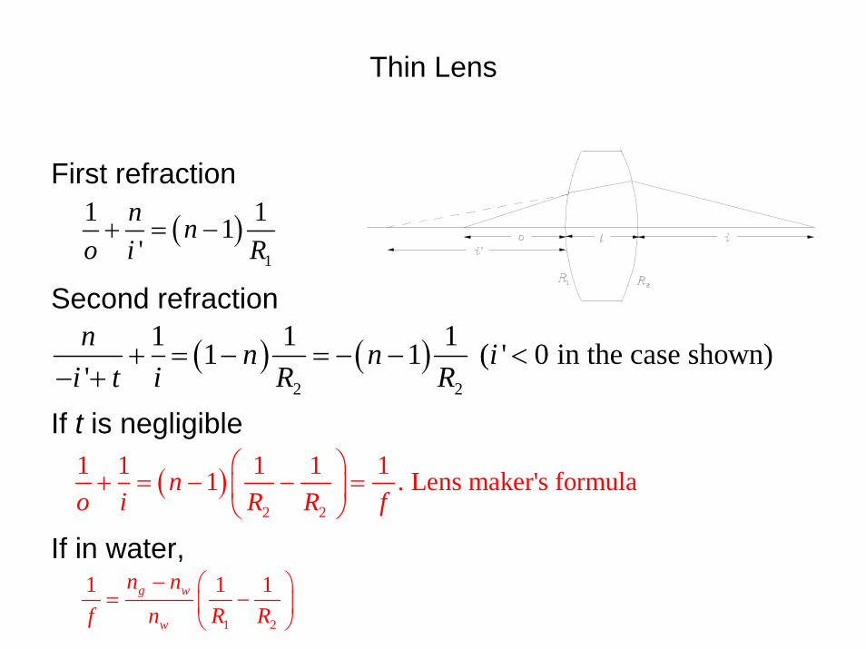
Thin Lens
First refraction
Second refraction
If t is negligible
If in water,
( )2
1 11 , ' 0 in the case shown'n n i
i i t R+ = − <
− +
( )1
1 11'
n no i R
+ = −
( )2 2
1 1 1 1 11 . Lens maker's formulano i R R f
⎛ ⎞+ = − − =⎜ ⎟
⎝ ⎠
1 2
1 1 1g w
w
n nf n R R
− ⎛ ⎞= −⎜ ⎟
⎝ ⎠
( ) ( )2 2
1 1 11 1 ( ' 0 in the case shown)'n n n i
i t i R R+ = − = − − <
− +
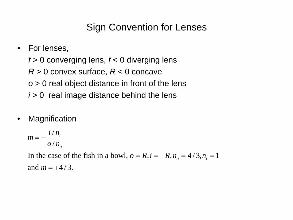
Sign Convention for Lenses
• For lenses, f > 0 converging lens, f < 0 diverging lensR > 0 convex surface, R < 0 concaveo > 0 real object distance in front of the lensi > 0 real image distance behind the lens
• Magnification
/ /
In the case of the fish in a bowl, , , 4 / 3, 1and 4 / 3.
i
o
o i
i nmo n
o R i R n nm
= −
= = − = == +
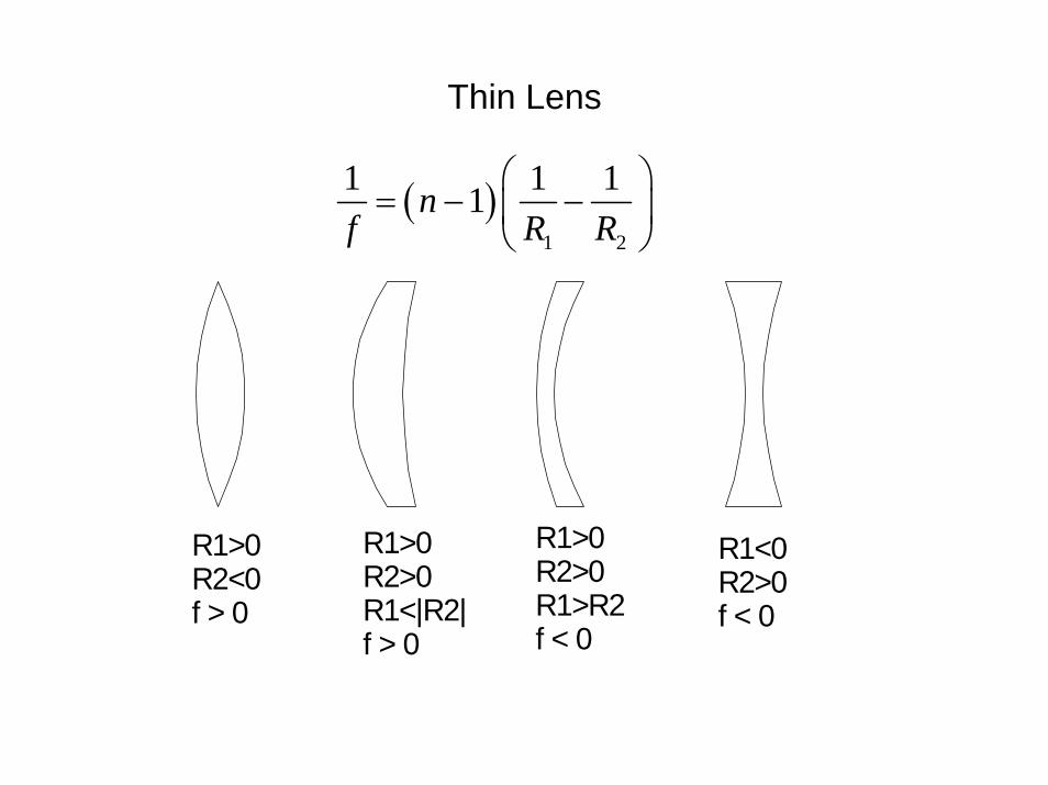
Thin Lens
R1>0R2<0f > 0
R1>0R2>0R1<|R2|f > 0
R1>0R2>0R1>R2f < 0
R1<0R2>0f < 0
( )1 2
1 1 11nf R R
⎛ ⎞= − −⎜ ⎟
⎝ ⎠

ExamplesExample: When a converging lens
of f = +30 cm is immersed in a liquid, it becomes a diverging lens of f = - 130 cm. If n (lens glass) = 1.5, what is n of the liquid?
( )1 2 1 2
1 2
1 1 1 1 1 1 11 ,30 15
In liquid,
1 1 1 1130
Then 1.696.
gair
g liq
liq liq
liq
nf R R R R
n nf n R R
n
⎛ ⎞= − − = − =⎜ ⎟
⎝ ⎠
− ⎛ ⎞= − = −⎜ ⎟
⎝ ⎠=
Example: Design lenses with f = +25 cm and – 25 cm given n(glass) = 1.5.
( )1 2 1 2
1 2
1 2
1 2
1 2
1 2
1 2
1 1 1 1 1 11 0.525
12.5 cm, (plano convex)25 cm (symmetric)
15 cm, 75 cm (meniscus)
1 1 1 10.525
12.5 cm, 25 cm, 8.33 cm, etc.
nf R R R RR RR RR R
f R RR RR R
⎛ ⎞ ⎛ ⎞= − − = − =⎜ ⎟ ⎜ ⎟
⎝ ⎠ ⎝ ⎠= = ∞= − == = −
⎛ ⎞= − = −⎜ ⎟
⎝ ⎠= − = ∞= =
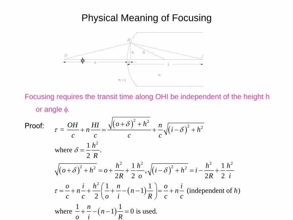
Physical Meaning of Focusing
Focusing requires the transit time along OHI be independent of the height h
or angle φ.
Proof:
φ
( )( )
( ) ( )
( )
( )
2 22 2 =
o hOH HI nn i hδ
τ δ+ +
+ = + − +
2
2 2 2 22 22 2
2
1where . 2
1 1,2 2 2 2
1 11 (independent of )2
1 1where 1 0 is used.
c c c chR
h h h ho h o i h iR o R i
o i h n o in n n hc c o i R c c
n no i R
δ
δ δ
τ
=
+ + = + + − + = − +
⎛ ⎞= + + + − − = +⎜ ⎟⎝ ⎠
+ − − =
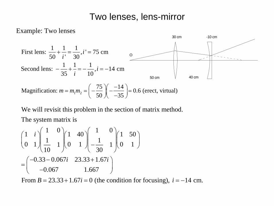
Two lenses, lens-mirrorExample: Two lenses
1 1 1First lens: , ' 75 cm50 ' 30
1 1 1Second lens: , 14 cm35 10
ii
ii
+ = =
− + = − = −
30 cm -10 cm
50 cm 40 cm
O
1 275 14Magnification: 0.6 (erect, virtual)50 35
m m m −⎛ ⎞⎛ ⎞= = − − =⎜ ⎟⎜ ⎟−⎝ ⎠⎝ ⎠
We will revisit this problem in the section of matrix method. The system matrix is
1 0 1 01 1 40 1 501 10 1 0 1 0 11 1
10 300.33 0.067 23.33 1.67
0.067 1.667From 23.33 1.6
i
i i
B
⎛ ⎞ ⎛ ⎞⎛ ⎞ ⎛ ⎞ ⎛ ⎞⎜ ⎟ ⎜ ⎟⎜ ⎟ ⎜ ⎟ ⎜ ⎟⎜ ⎟ ⎜ ⎟−⎝ ⎠ ⎝ ⎠ ⎝ ⎠⎝ ⎠ ⎝ ⎠− − +⎛ ⎞
= ⎜ ⎟−⎝ ⎠= + 7 0 (the condition for focusing), 14 cm.i i= = −
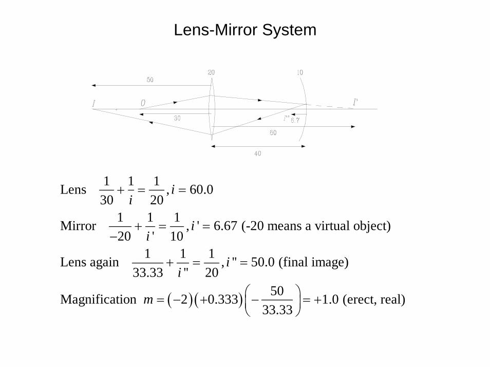
Lens-Mirror System
( ) ( )
1 1 1Lens , 60.030 20
1 1 1Mirror , ' 6.67 (-20 means a virtual object)20 ' 10
1 1 1Lens again , '' 50.0 (final image)33.33 '' 20
50Magnification 2 0.333 1.0 (erect, real)33.33
ii
ii
ii
m
+ = =
+ = =−
+ = =
⎛ ⎞= − + − = +⎜ ⎟⎝ ⎠
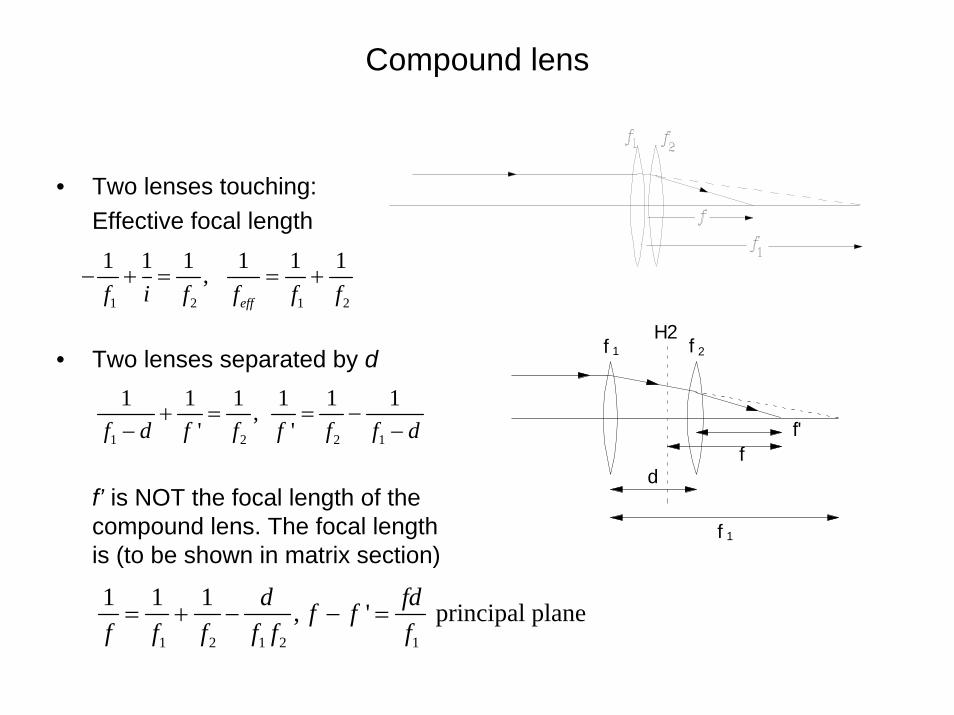
Compound lens
• Two lenses touching: Effective focal length
• Two lenses separated by d
f’ is NOT the focal length of the compound lens. The focal length is (to be shown in matrix section)
1 2 1 2
1 1 1 1 1 1, efff i f f f f
− + = = +
1 2 2 1
1 1 1 1 1 1, ' 'f d f f f f f d
+ = = −− −
1 2 1 2 1
1 1 1 , ' principal planed fdf ff f f f f f
= + − − =
f f1 2
f'
d
f 1
f
H2

Myopia
Myopia correction
d
f = -d
Myopia is caused by too short a focal length of the eye lens.Placing a diverging lens can correct it. If the farpoint of the eye is , the focal length of the correcting lens is . Let the eye lens
df d= − focal length be and the eye lens
retina distance be . Without lens,1 1 1 1 1 1 1. With lens . Then .
e
e
e e e e
fo
f dd o f o f f
+ = + = + = −∞
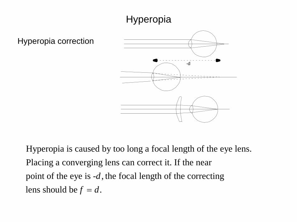
Hyperopia
Hyperopia correction
Hyperopia is caused by too long a focal length of the eye lens.Placing a converging lens can correct it. If the nearpoint of the eye is - , the focal length of the correcting lens should be .
df d=
-d
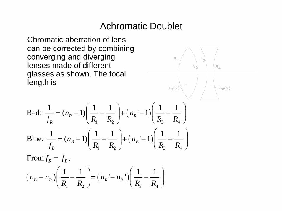
Achromatic DoubletChromatic aberration of lens can be corrected by combining converging and diverging lenses made of different glasses as shown. The focal length is
( )
( )
( ) ( )
1 2 3 4
1 2 3 4
1 2 3 4
1 1 1 1 1Red: ( 1) ' 1
1 1 1 1 1Blue: ( 1) ' 1
From ,
1 1 1 1' '
R RR
B BB
R B
B R R B
n nf R R R R
n nf R R R R
f f
n n n nR R R R
⎛ ⎞⎛ ⎞= − − + − −⎜ ⎟⎜ ⎟
⎝ ⎠ ⎝ ⎠⎛ ⎞⎛ ⎞
= − − + − −⎜ ⎟⎜ ⎟⎝ ⎠ ⎝ ⎠
=
⎛ ⎞⎛ ⎞− − = − −⎜ ⎟⎜ ⎟
⎝ ⎠ ⎝ ⎠
1 2
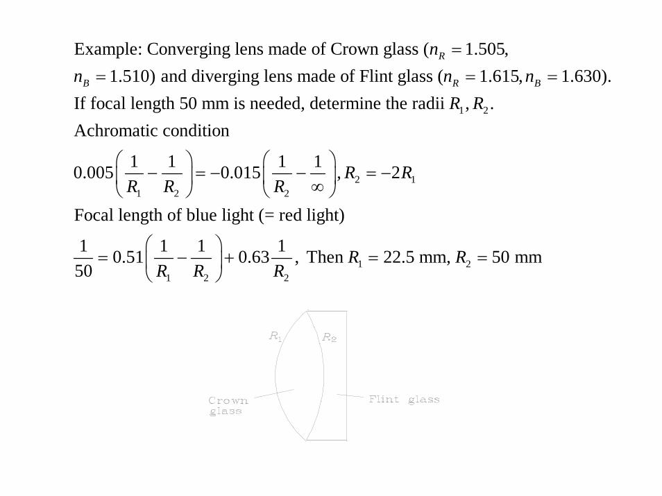
Example: Converging lens made of Crown glass ( 1.505,1.510) and diverging lens made of Flint glass ( 1.615, 1.630).
If focal length 50 mm is needed, determine the radii , .Achromatic condit
R
B R B
nn n n
R R
== = =
2 11 2 2
1 21 2 2
ion
1 1 1 10.005 0.015 , 2
Focal length of blue light (= red light)
1 1 1 10.51 0.63 , Then 22.5 mm, 50 mm50
R RR R R
R RR R R
⎛ ⎞ ⎛ ⎞− = − − = −⎜ ⎟ ⎜ ⎟∞⎝ ⎠ ⎝ ⎠
⎛ ⎞= − + = =⎜ ⎟
⎝ ⎠

Achromatic Compound Lens
( ) ( )
1 2 1 2
2
1 2 3 4 1 2 3 4
1 2
The effective focal length of compound lens is1 1 1=
1 1 1 1 1 1 1 11 - 1
If , the focal length becomes independent of the wavelength.2
(Assignmen
df f f f f
n n dR R R R R R R R
f fd f
+ −
⎛ ⎞ ⎛ ⎞⎛ ⎞= − − + − − − −⎜ ⎟ ⎜ ⎟⎜ ⎟
⎝ ⎠⎝ ⎠ ⎝ ⎠+
=
t Problem)
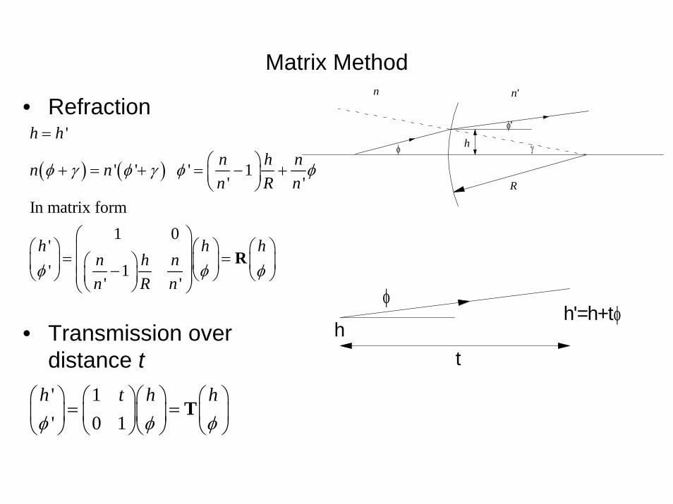
Matrix Method
( ) ( )
'
' ' ' 1' '
In matrix form1 0
'1'
' '
h hn h nn nn R n
h h hn h nn R n
φ γ φ γ φ φ
φ φ φ
=
⎛ ⎞+ = + = − +⎜ ⎟⎝ ⎠
⎛ ⎞⎛ ⎞ ⎛ ⎞ ⎛ ⎞⎜ ⎟= =⎛ ⎞⎜ ⎟ ⎜ ⎟ ⎜ ⎟⎜ ⎟−⎝ ⎠ ⎝ ⎠ ⎝ ⎠⎜ ⎟⎜ ⎟⎝ ⎠⎝ ⎠
R
hh'=h+t
t
φφ
R
φ
φ'
n n'
h γ
• Refraction
• Transmission over distance t' 1' 0 1
h t h hφ φ φ
⎛ ⎞ ⎛ ⎞⎛ ⎞ ⎛ ⎞= =⎜ ⎟ ⎜ ⎟⎜ ⎟ ⎜ ⎟
⎝ ⎠ ⎝ ⎠⎝ ⎠ ⎝ ⎠T

Matrix of Thin Lens
2 1
1
1 2
1 2 1 2 2
1 1 1 1'
1' and '
1 0'
1 1'
Two lenses separated by 1 0 1 0
11 11 10 1
11 1 1 ,
1 1 1 eff
ho i f f
h h hf
h h
fd
d
f f
d df dC
d d f f f ff f f f f
φ φ
φ φ
φ φ
+ = → − =
= − + =
⎛ ⎞⎛ ⎞ ⎛ ⎞⎜ ⎟=⎜ ⎟ ⎜ ⎟⎜ ⎟−⎝ ⎠ ⎝ ⎠⎜ ⎟
⎝ ⎠
⎛ ⎞ ⎛ ⎞⎛ ⎞⎜ ⎟ ⎜ ⎟⎜ ⎟⎜ ⎟ ⎜ ⎟− −⎝ ⎠⎜ ⎟ ⎜ ⎟
⎝ ⎠ ⎝ ⎠⎛ ⎞−⎜ ⎟⎜ ⎟= = − = + −⎜ ⎟− − + −⎜ ⎟⎝ ⎠
1 2
, ' Aff C
= −
φ φ'
oi
fγh
d
f1 f2
f'

Single Thin Lens
If an object is at from the first lens and image at from the second lens, total matrix is
1 01 1
1 10 1 0 1
1 0
11 1
0 determines th
oi
i o
fi oi io if f o
oof if f
B
⎛ ⎞⎛ ⎞ ⎛ ⎞⎜ ⎟⎜ ⎟ ⎜ ⎟⎜ ⎟−⎝ ⎠ ⎝ ⎠⎜ ⎟
⎝ ⎠⎛ ⎞ ⎛ ⎞− + − −⎜ ⎟ ⎜ ⎟⎜ ⎟ ⎜ ⎟= =⎜ ⎟ ⎜ ⎟− −− − ⎜ ⎟⎜ ⎟ ⎝ ⎠⎝ ⎠= e image distance
1 1 1 , lens formula
Magnification = 1
i f oi iAf o
= −
= − = −
f
o i
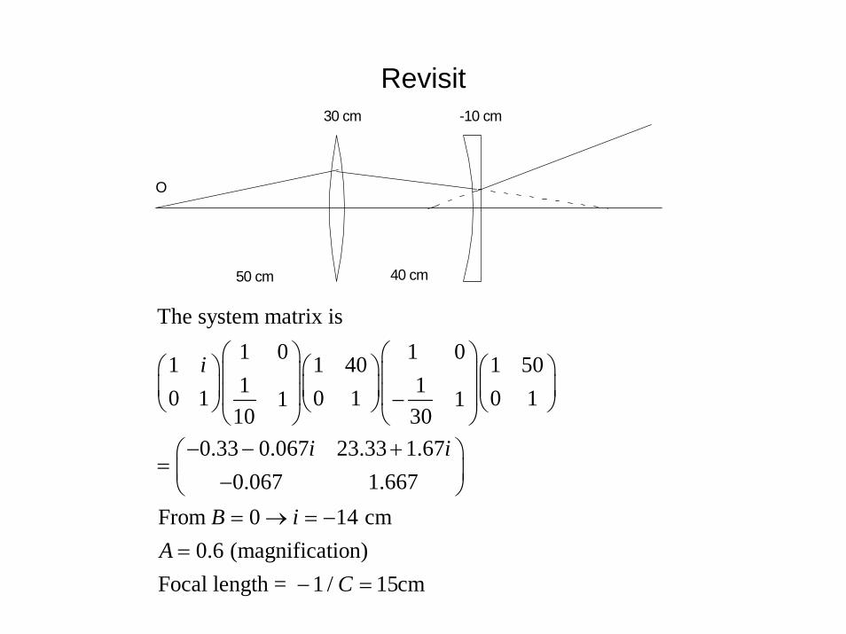
Revisit30 cm -10 cm
50 cm 40 cm
O
The system matrix is1 0 1 01 1 40 1 501 10 1 0 1 0 11 1
10 300.33 0.067 23.33 1.67
0.067 1.667From 0 14 cm
0.6 (magnification)Focal length = 1 / 15cm
i
i i
B iA
C
⎛ ⎞ ⎛ ⎞⎛ ⎞ ⎛ ⎞ ⎛ ⎞⎜ ⎟ ⎜ ⎟⎜ ⎟ ⎜ ⎟ ⎜ ⎟⎜ ⎟ ⎜ ⎟−⎝ ⎠ ⎝ ⎠ ⎝ ⎠⎝ ⎠ ⎝ ⎠− − +⎛ ⎞
= ⎜ ⎟−⎝ ⎠= → = −
=− =
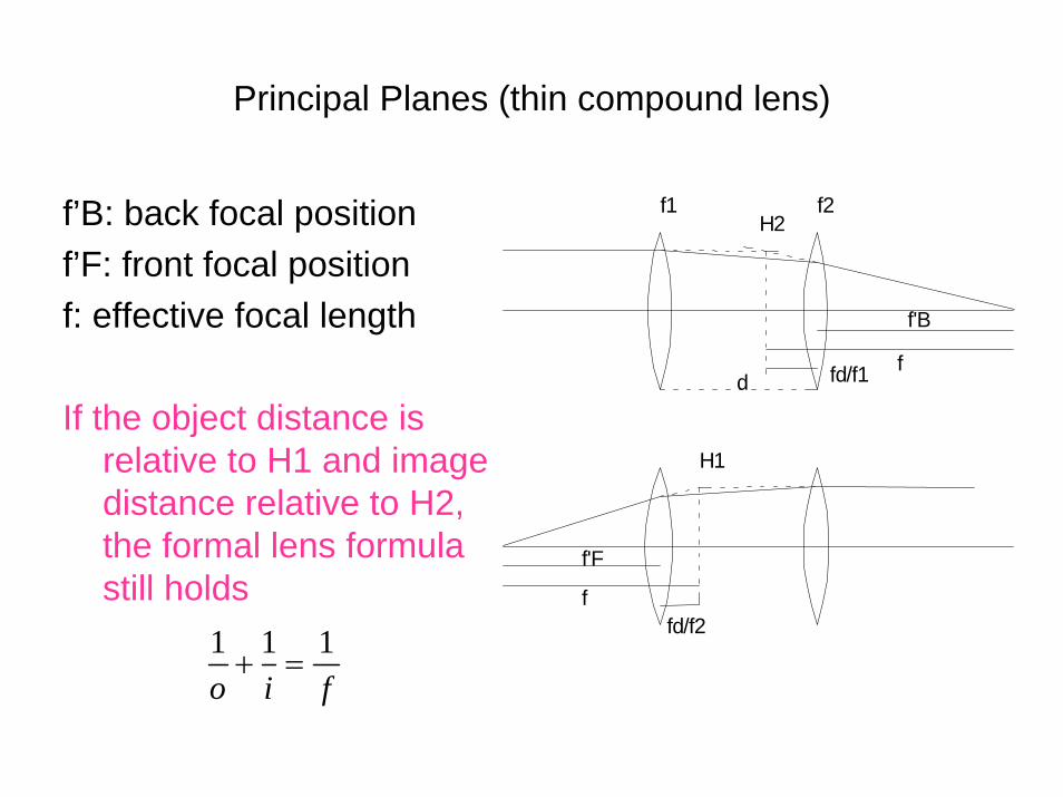
Principal Planes (thin compound lens)
f’B: back focal positionf’F: front focal positionf: effective focal length
If the object distance is relative to H1 and image distance relative to H2, the formal lens formula still holds
f
f'B
d
H2f1 f2
fd/f1
H1
fd/f2f
f'F
1 1 1o i f
+ =

1
2
For the compound lens in the previous example,15 40H2 at 20 cm to the left of lens 2
3015 40H1 at 60 cm to the right of lens 1 = 60 cm
10to the left of lens 1Then the object distance realt
fdffdf
×= =
×= = −
−
ive to H1 is 10 cm.1 1 1From , we find 6 cm to the right of H2 or14 cm to the left of lens 2.10 15
ii
−
+ = =−
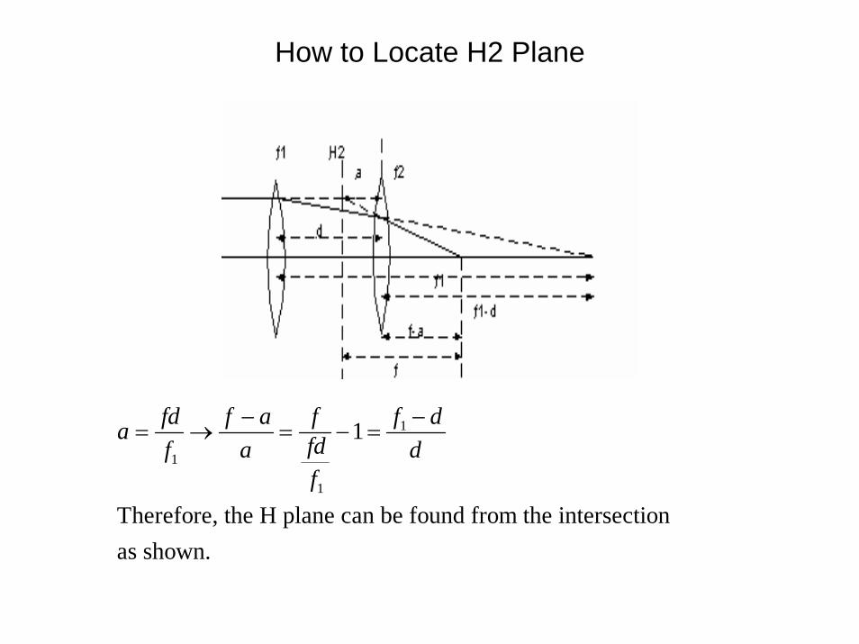
How to Locate H2 Plane
1
1
1
1
Therefore, the H plane can be found from the intersectionas shown.
fd f a f f da fdf a df
− −= → = − =

Thick Lens
Total lens matrix is
( )
( ) ( ) ( )
( ) ( )
2 1
1
2
1 2
2
1 2 1
1 2 2
1 01 01
1 1 1 11 10 1
11 1
11 11 1 1
The effective foca
1
l length s
1
i
11
1 gg
g gg g
g g
gg g
g g
g
tn n
R n R n
t tR n n
n t tn nR R n
n tn
f R
R R R
R n
n
R
⎛ ⎞⎛ ⎞⎜ ⎟⎛ ⎞⎜ ⎟ ⎛ ⎞⎜ ⎟⎜ ⎟⎜ ⎟− −⎜ ⎟⎝ ⎠⎜ ⎟ ⎜ ⎟⎜ ⎟⎝ ⎠ ⎝ ⎠⎝ ⎠
⎛ ⎞⎛ ⎞− −⎜ ⎟⎜ ⎟⎜ ⎟⎜ ⎟⎝ ⎠
= ⎜ ⎟−⎜ ⎟⎛ ⎞
− − − − + −⎜ ⎟⎜ ⎟⎝ ⎠
−⎛ ⎞= − − +⎜ ⎟
⎝ ⎠
⎝ ⎠
1 2 1 2
1
2 1 2 1 2
2
1 1 1cf. (compound lens)
H2 at to the left of second vertex. H1 at to the right of firs
1 1 ,
t vertex.g
g
df f f f f
ft ftf n f n
tR f f n f f
= + − = + −
R R
t
1 2
gnf'
f
H2
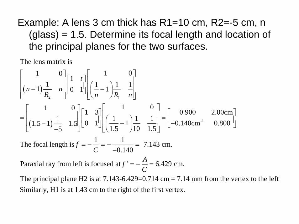
Example: A lens 3 cm thick has R1=10 cm, R2=-5 cm, n (glass) = 1.5. Determine its focal length and location of the principal planes for the two surfaces.
( )
( )
2 1
-1
The lens matrix is1 01 0
11 1 1 11 10 1
1 01 0 1 3 0.900 2.00cm1 1 11 10 1 0.140cm 0.8001.5 1 1.5
1.5 10 1.551 1The focal length is
0
tn n
R n R n
fC
⎡ ⎤⎡ ⎤⎡ ⎤ ⎢ ⎥⎢ ⎥ ⎛ ⎞⎢ ⎥ ⎢ ⎥⎢ ⎥− −⎜ ⎟⎣ ⎦ ⎢ ⎥⎢ ⎥ ⎝ ⎠⎣ ⎦ ⎣ ⎦
⎡ ⎤⎡ ⎤ ⎡ ⎤ ⎡ ⎤⎢ ⎥⎢ ⎥= =⎛ ⎞⎢ ⎥ ⎢ ⎥⎢ ⎥⎢ ⎥ − −− ⎣ ⎦ ⎣ ⎦⎜ ⎟⎢ ⎥−⎣ ⎦ ⎝ ⎠⎣ ⎦
= − = −−
7.143 cm..140
Paraxial ray from left is focused at ' 6.429 cm.
The principal plane H2 is at 7.143-6.429=0.714 cm = 7.14 mm from the vertex to the leftSimilarly, H1 is at 1.43 cm to the right of t
AfC
=
= − =
he first vertex.

( )
-1
For light coming from right, the order of matrices is reversed.1 01 0 1 3
1 1 11 10 11.5 1 1.51.5 5 1.510
0.8 2.00cm0.140cm 0.900
1 1The focal length is 7.143 cm0.140
fC
⎡ ⎤⎡ ⎤ ⎡ ⎤ ⎢ ⎥⎢ ⎥ ⎛ ⎞⎢ ⎥ ⎢ ⎥⎢ ⎥ −− ⎣ ⎦ ⎜ ⎟⎢ ⎥−⎣ ⎦ ⎝ ⎠⎣ ⎦⎡ ⎤
= ⎢ ⎥−⎣ ⎦
= − = − =−
(unchanged)
Paraxial ray from right is focused at ' 5.714 cm.
The principal plane H1 is at 7.143-5.714=0.714 cm = 1.429 cm from the vertex to the right
AfC
= − =
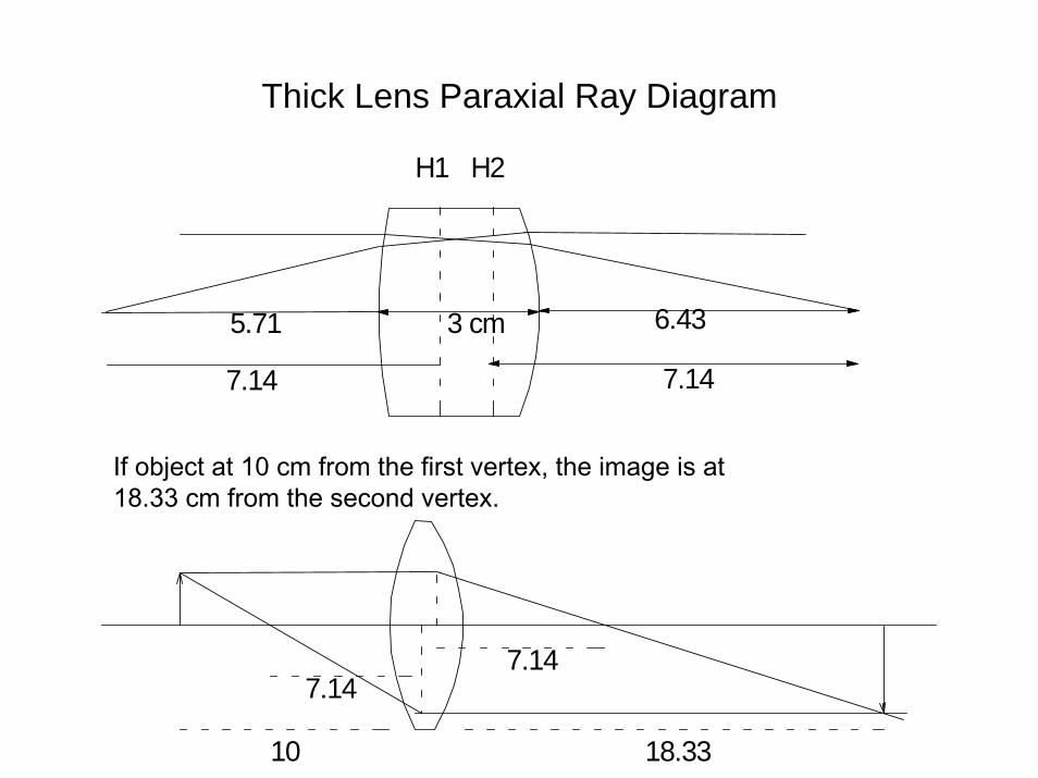
Thick Lens Paraxial Ray Diagram
3 cm 6.43
7.14
H2
5.71
H1
7.14
10 18.33
7.147.14
If object at 10 cm from the first vertex, the image is at 18.33 cm from the second vertex.
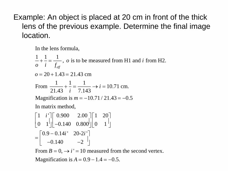
Example: An object is placed at 20 cm in front of the thick lens of the previous example. Determine the final image location.
In the lens formula, 1 1 1 , is to be measured from H1 and from H2.
20 1.43 21.43 cm1 1 1From 10.71 cm.
21.43 7.143Magnification is 10.71 / 21.43 0.5In matrix method,1 ' 0.900 2.00 1
eff
o io i f
o
ii
m
i
+ =
= + =
+ = → =
= − = −
⎡ ⎤⎢ ⎥⎣ ⎦
0 1 200.140 0.800 0 1
0.9 0.14 ' 20-2 '0.140 2
From 0, ' 10 measured from the second vertex.Magnification is 0.9 1.4 0.5.
i i
B iA
⎡ ⎤ ⎡ ⎤⎢ ⎥ ⎢ ⎥−⎣ ⎦ ⎣ ⎦
−⎡ ⎤= ⎢ ⎥− −⎣ ⎦
= → == − = −
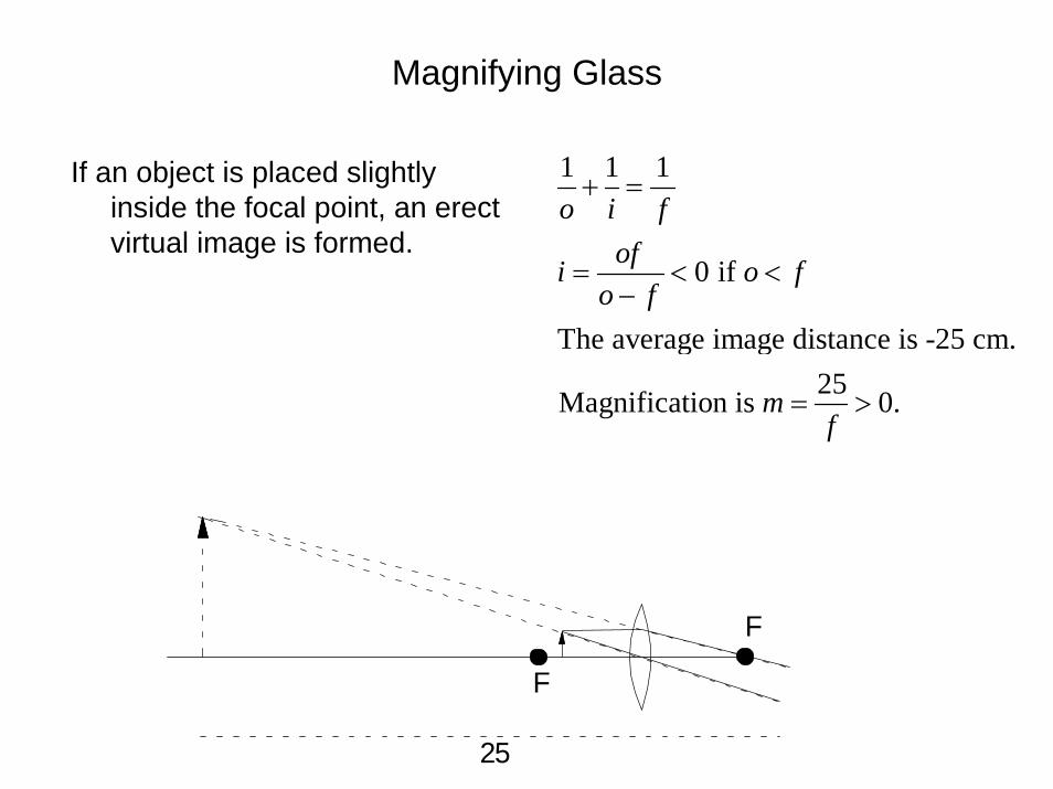
Magnifying Glass
If an object is placed slightly inside the focal point, an erect virtual image is formed.
1 1 1
0 if
The average image distance is -25 cm. 25Magnification is 0.
o i fofi o f
o f
mf
+ =
= < <−
= >
25
F
F
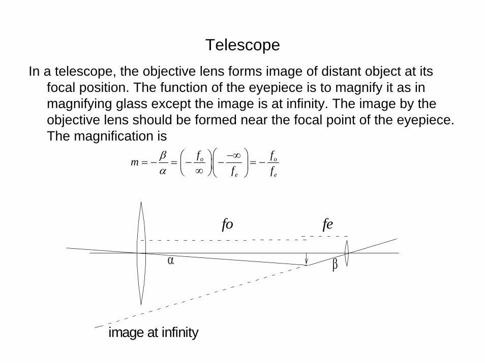
TelescopeIn a telescope, the objective lens forms image of distant object at its
focal position. The function of the eyepiece is to magnify it as in magnifying glass except the image is at infinity. The image by the objective lens should be formed near the focal point of the eyepiece. The magnification is
o o
e e
f fmf f
βα
⎛ ⎞−∞⎛ ⎞= − = − − = −⎜ ⎟⎜ ⎟∞⎝ ⎠ ⎝ ⎠
image at infinity
α β
fo fe
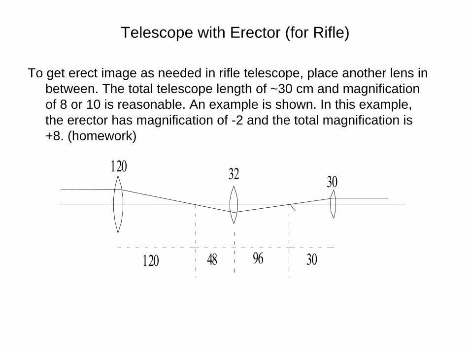
Telescope with Erector (for Rifle)
To get erect image as needed in rifle telescope, place another lens in between. The total telescope length of ~30 cm and magnification of 8 or 10 is reasonable. An example is shown. In this example, the erector has magnification of -2 and the total magnification is +8. (homework)
120 32 30
120 48 96 30
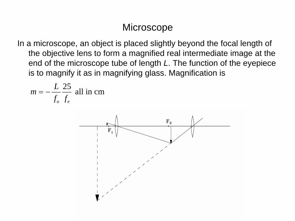
MicroscopeIn a microscope, an object is placed slightly beyond the focal length of
the objective lens to form a magnified real intermediate image at the end of the microscope tube of length L. The function of the eyepiece is to magnify it as in magnifying glass. Magnification is
25 all in cmo e
Lmf f
= −