Embed Size (px)
DESCRIPTION
Honeywell
Citation preview

Experion
Series C I/O User's Guide
EP-DCX474 R301.1
4/07

ii Experion Series C I/O User's Guide R301.1 Honeywell 4/07
Notices and Trademarks
Copyright 2006 by Honeywell International Inc. Release 301.1 November 27, 2006
While this information is presented in good faith and believed to be accurate, Honeywell disclaims the implied warranties of merchantability and fitness for a particular purpose and makes no express warranties except as may be stated in its written agreement with and for its customers.
In no event is Honeywell liable to anyone for any indirect, special or consequential damages. The information and specifications in this document are subject to change without notice.
Honeywell, PlantScape, Experion, and TotalPlant are registered trademarks of Honeywell International Inc.
Other brand or product names are trademarks of their respective owners.
Honeywell International
Process Solutions
2500 West Union Hills
Phoenix, AZ 85027
1-800 343-0228

R301.1 Experion Series C I/O User's Guide iii 4/07 Honeywell
About This Document The procedures in this guide are intended to give you the ability to perform basic tasks with the Series C I/O such as configuring hardware devices, continuous control strategies. Respective forms are shown to illustrate a procedure/concept only.
Release Information
Document Name Document ID Release Number
Publication Date
4/07 Series C I/O User's Guide - cio_g EP-DCX474 301.1
Original release date 11/06
Updates The following list identifies all updates to this document since the R301.1 11/06 release.
Updates
Fiber Optic Extender information added
Series C Anlaog Input 6 inch non-redundant field wiring connection diagram modified
Relay Extension board – added model number
Contacts
World Wide Web The following Honeywell web sites may be of interest to Process Solutions customers.
Honeywell Organization WWW Address (URL)
Corporate http://www.honeywell.com
Honeywell Process Solutions http://hpsweb.honeywell.com

Contacts
iv Experion Series C I/O User's Guide R301.1 Honeywell 4/07
Telephone Contact us by telephone at the numbers listed below.
Location Organization Phone
United States and Canada
Honeywell IAC Solution Support Center
1-800-822-7673
Europe Honeywell TAC-EMEA +32-2-728-2704
Pacific Honeywell Global TAC - Pacific
1300-300-4822 (toll free within Australia) +61-8-9362-9559 (outside Australia)
India Honeywell Global TAC - India
+91-20-2682-2458
Korea Honeywell Global TAC - Korea
+82-2-799-6317
People’s Republic of China
Honeywell Global TAC - China
+86-10-8458-3280 ext. 361
Singapore Honeywell Global TAC - South East Asia
+65-6580-3500
Taiwan Honeywell Global TAC - Taiwan
+886-7-323-5900
Japan Honeywell Global TAC - Japan
+81-3-5440-1303
Elsewhere Call your nearest Honeywell office.

Symbol Definitions
R301.1 Experion Series C I/O User's Guide v 4/07 Honeywell
Symbol Definitions The following table lists those symbols used in this document to denote certain conditions.
Symbol Definition
ATTENTION: Identifies information that requires special consideration.
TIP: Identifies advice or hints for the user, often in terms of performing a task.
REFERENCE -EXTERNAL: Identifies an additional source of information outside of the bookset.
REFERENCE - INTERNAL: Identifies an additional source of information within the bookset.
CAUTION
Indicates a situation which, if not avoided, may result in equipment or work (data) on the system being damaged or lost, or may result in the inability to properly operate the process.
CAUTION: Indicates a potentially hazardous situation which, if not avoided, may result in minor or moderate injury. It may also be used to alert against unsafe practices.
CAUTION symbol on the equipment refers the user to the product manual for additional information. The symbol appears next to required information in the manual.
WARNING: Indicates a potentially hazardous situation, which, if not avoided, could result in serious injury or death.
WARNING symbol on the equipment refers the user to the product manual for additional information. The symbol appears next to required information in the manual.

Symbol Definitions
vi Experion Series C I/O User's Guide R301.1 Honeywell 4/07
Symbol Definition
WARNING, Risk of electrical shock: Potential shock hazard where HAZARDOUS LIVE voltages greater than 30 Vrms, 42.4 Vpeak, or 60 VDC may be accessible.
ESD HAZARD: Danger of an electro-static discharge to which equipment may be sensitive. Observe precautions for handling electrostatic sensitive devices.
Protective Earth (PE) terminal: Provided for connection of the protective earth (green or green/yellow) supply system conductor.
Functional earth terminal: Used for non-safety purposes such as noise immunity improvement. NOTE: This connection shall be bonded to Protective Earth at the source of supply in accordance with national local electrical code requirements.
Earth Ground: Functional earth connection. NOTE: This connection shall be bonded to Protective Earth at the source of supply in accordance with national and local electrical code requirements.
Chassis Ground: Identifies a connection to the chassis or frame of the equipment shall be bonded to Protective Earth at the source of supply in accordance with national and local electrical code requirements.

R301.1 Experion Series C I/O User's Guide vii 4/07 Honeywell
Contents
INTRODUCTION .....................................................................................1 About this guide......................................................................................................... 1
Intended audience..................................................................................................................1 Prerequisite Skills...................................................................................................................1 Online documentation reference ............................................................................................1 Locating related documentation .............................................................................................1 Terms and acronyms .............................................................................................................2
SERIES C I/O PURPOSE........................................................................5 Overview ..................................................................................................................... 5 Comparing Process Manager I/O and Series C I/O................................................. 5 What is I/O? ................................................................................................................ 6
Series C and I/O.....................................................................................................................6
SERIES C I/O PLANNING AND DESIGN ...............................................7 Overview ..................................................................................................................... 7 General Planning References ................................................................................... 7 Series C I/O appearance and features ..................................................................... 7
New look and feel...................................................................................................................7 Series C I/O and C300 topology.............................................................................. 10
Examining the topology rules ...............................................................................................12 Supported Series C I/O modules............................................................................ 13
Available Series C I/O modules............................................................................................13 Identifying supported Series C I/O modules .........................................................................14
Supported Series C I/O options.............................................................................. 15 Available Series C I/O options..............................................................................................15 Inspecting the Series C I/O library........................................................................................15 Inspecting IOM function blocks ............................................................................................16 Inspecting channel function blocks.......................................................................................16 Defining module containment...............................................................................................16
I/O Link performance specifications...................................................................... 18 Reviewing Link Unit utilization..............................................................................................18

Contents Symbol Definitions
viii Experion Series C I/O User's Guide R301.1 Honeywell 4/07
Reducing I/O Link traffic ...................................................................................................... 19 Event collection ................................................................................................................... 19 PV and Back calculation scanning ...................................................................................... 20
SERIES C I/O INSTALLATION AND UPGRADES .............................. 21 Overview....................................................................................................................21 Installation Declarations ..........................................................................................21
Introduction ......................................................................................................................... 22 Cabling ................................................................................................................................ 24
Installing the IOTA onto the carrier ........................................................................26 Prerequisites ....................................................................................................................... 26 Considerations .................................................................................................................... 26 Mounting the IOTA .............................................................................................................. 26
Replacing an I/O IOTA..............................................................................................28 Mounting the I/O module onto the IOTA ................................................................29
Prerequisites ....................................................................................................................... 29 Mounting the module........................................................................................................... 29
Replacing an I/O module..........................................................................................30 Prerequisites ....................................................................................................................... 30 Considerations .................................................................................................................... 30 To replace an I/O module.................................................................................................... 30
Grounding and power considerations - IOTA boards ..........................................31 Attaching the IOTA board.................................................................................................... 31 Testing for power................................................................................................................. 31
Connecting IOMs and field devices via I/O Termination Assemblies .................34 IOTAs wiring diagrams ........................................................................................................ 34
Powering the Series C system ................................................................................38 Supplying power to I/O modules.......................................................................................... 38
Fusing – IOTA boards ..............................................................................................39 Protecting the Series C I/O components ............................................................................. 39
IOTA pinouts .............................................................................................................40 Field wiring .......................................................................................................................... 40 Analog Input IOTA Models CU/CC-TAIX01, CU/CC-TAIX11 .............................................. 40 Analog Input wiring.............................................................................................................. 45 Analog Output IOTA Models CU/CC-TAOX01, CU/CC-TAOX11 ........................................ 56 Low Level Analog Input Mux (LLMUX) IOTA Models CU/CC-TAIM01 ................................ 61 Digital Input High Voltage IOTA Models CU/CC-TDI120, CU/CC-TDI130, CU/CC-TDI240, CU/CC-TDI250 .................................................................................................................... 66 Digital Input 24V IOTA Models CU/CC-TDIL01, CU/CC-TDIL11......................................... 71

About this guide Intended audience
R301.1 Experion Series C I/O User's Guide ix 4/07 Honeywell
Digital Output 24V IOTA Models CU/CC-TDOB01, CU/CC-TDOB11 ..................................81 Digital Output Relay Module IOTA Models CU/CC-TDOR01, CU/CC-TDOR11...................88 Digital Output Relay Extender board Models CC-SDOR01..................................................90
Upgrading firmware in Series C I/O components ................................................. 95
SERIES C I/O CONFIGURATION FORM REFERENCE ......................97 Overview ................................................................................................................... 97 Determining Series C I/O block redundancy......................................................... 97
Main tab checkbox invokes redundancy ..............................................................................97 Switchover and Secondary readiness ................................................................... 98 Failure conditions and switchover......................................................................... 99 Configuration tools................................................................................................ 100
Using Control Builder to create control strategies ..............................................................100 Configuring the Main tab - IOM block .................................................................. 100
Configuring modules - Main tab .........................................................................................100 Configuring the Status Data tab - IOM block ...................................................... 104
Configuring modules - Status Data tab ..............................................................................104 Configuring the Maintenance tab - IOM block .................................................... 107
Configuring modules - Maintenance tab.............................................................................107 Configuring Box Soft Failures tab - IOM block ................................................... 110
Configuring modules - Box Soft Failures tab ......................................................................110 Configuring Channel Soft Failures tab - IOM block............................................ 112
Configuring modules - Channel Soft Failures tab...............................................................112 Configuring Server History tab - IOM block ........................................................ 114
Configuring modules - Server History tab...........................................................................114 Configuring Server Displays tab - IOM block...................................................... 118
Configuring modules - Server Displays tab ........................................................................118 Configuring Control Confirmation tab - IOM block ............................................ 122
Configuring modules - Control Confirmation tab ................................................................122 Configuring Identification tab - IOM block .......................................................... 124
Configuring modules - Identification tab .............................................................................124 Configuring modules - QVCS tab .......................................................................................128
Configuring the Calibration tab - IOM block ....................................................... 130 Configuring modules - Calibration tab ................................................................................130

Contents Symbol Definitions
x Experion Series C I/O User's Guide R301.1 Honeywell 4/07
Configuring HART Status tab - IOM block ...........................................................133 Configuring modules HART - Status tab ........................................................................... 133
Configuring the Configuration tab - Channel block............................................135 Configuring modules - Identification tab ............................................................................ 135
Configuring HART Configuration tab - Channel block .......................................137 Configuring modules – HART Configuration tab................................................................ 137
Configuring HART Device Status tab - Channel block .......................................140 Configuring modules - Identification tab ............................................................................ 140
Configuring HART Identification tab - Channel block ........................................143 Configuring modules - Identification tab ............................................................................ 143
Configuring HART Variables tab - Channel block...............................................146 Configuring modules - Identification tab ............................................................................ 146
Configuring HART Notifications tab - Channel block.........................................149 Configuring modules - Identification tab ............................................................................ 149
Configuring Dependencies tab - Channel block .................................................152 Configuring modules - Dependencies tab ......................................................................... 152
Configuring Template Defining tab - Channel block...........................................154 Configuring modules - Identification tab ............................................................................ 154
SERIES C I/O CONFIGURATION ...................................................... 157 Adding an IOM to Project.......................................................................................157
Using the File menu method ............................................................................................. 157 Using the drag and drop method ....................................................................................... 159
Assigning an IOM to an IOLINK in the Project tab..............................................160 Using the Assignment dialog box ...................................................................................... 160
Adding an IOC block to a Control Module ...........................................................161 Using the Project tab drag and drop.................................................................................. 161 Using the Library tab - drag and drop................................................................................ 163
Assigning an IOC block to an IOM........................................................................166 IOC block assignment ....................................................................................................... 166
Unassigning an IOC block from an IOM...............................................................168 IOC block unassignment ................................................................................................... 168
Defining Channel blocks........................................................................................170 Overview ........................................................................................................................... 170 Common features of I/O channel blocks ........................................................................... 170 Defining Mode and Attribute settings................................................................................. 170 Enabling HART.................................................................................................................. 179

About this guide Intended audience
R301.1 Experion Series C I/O User's Guide xi 4/07 Honeywell
Comparing parameters between Series C and PMIO ........................................................181 Using Block Copy...............................................................................................................181
Defining AI Channel Blocks .................................................................................. 182 Overview ............................................................................................................................182 Determining PV Characterization .......................................................................................183 Determining Linear Conversion..........................................................................................185 Determining Square Root Conversion................................................................................186 Determining Thermal Conversion.......................................................................................187 Comparing parameters between Series C and PMIO that support AI ................................188
Defining AO Channel Blocks ................................................................................ 190 Overview ............................................................................................................................190 Determining Direct/Reverse Output ...................................................................................191 Determining Output Characterization .................................................................................191 Determining Calibration Compensation..............................................................................192 Determining Modes ............................................................................................................192 Determining Output Verification .........................................................................................193 Comparing parameters between Series C and PMIO that support AO ..............................193
Defining DI Channel Blocks .................................................................................. 193 Overview ............................................................................................................................193 Determining Status Digital Input channel ...........................................................................194 Determining Latched Digital Input channel.........................................................................195 Comparing parameters between Series C and PMIO that support DI................................195
Defining DO Channel Blocks ................................................................................ 196 Overview ............................................................................................................................196 Determining Status Output type .........................................................................................197 Determining Pulse Width Modulated (PWM) Output type...................................................198 Determining On-Pulse and Off-Pulse Output type..............................................................199 Determining Initialization Request Flag..............................................................................200 Determining Modes ............................................................................................................200 Determining Output Verification .........................................................................................201 Determining Over-current protection ..................................................................................201 Comparing parameters between Series C and PMIO that support DO ..............................201
SERIES C I/O OPERATIONS..............................................................203 Overview ................................................................................................................. 203 Reviewing the Control Builder icons ................................................................... 203
Series C I/O block icons .....................................................................................................203 IOLink icons .......................................................................................................................205 Block icons .........................................................................................................................206 Channel icons ....................................................................................................................207
Series C I/O LED Descriptions.............................................................................. 208

Contents Symbol Definitions
xii Experion Series C I/O User's Guide R301.1 Honeywell 4/07
Powering up the IOM..............................................................................................210 Activating a control strategy from the Monitoring tab .......................................211
Starting an IOM ................................................................................................................. 211 Activating HART .....................................................................................................212
Assigning a channel to HART – Series C.......................................................................... 212 Enabling HART Alarm and Events – Series C................................................................... 213
IOM configuration values not copied during Block Copy operation.................214
SERIES C I/O LOADING .................................................................... 215 Loading Series C I/O components........................................................................215
Load order guidelines........................................................................................................ 215 Loading an IOLINK .................................................................................................216
IOLINK Load with Contents............................................................................................... 216 Loading the IOM block the first time ....................................................................216
Loading the IOM block present on the IOLINK.................................................................. 216 Loading with the IOM block missing on the IOLINK .......................................................... 220 Reloading the IOM block from Project or Monitoring ......................................................... 221 Reviewing IOM reconfiguration rules................................................................................. 222
Common I/O block load activities.........................................................................223 Uploading the I/O block ..................................................................................................... 223 Update to Project............................................................................................................... 223 Using IOM Checkpoint ...................................................................................................... 223
Loading a CM ..........................................................................................................224 Loading the CM the first time............................................................................................. 224 Reloading the CM from Project or Monitoring.................................................................... 225
Setting Priority IOMs ..............................................................................................227 To set the Priority IOM ...................................................................................................... 227
SERIES C I/O LINK FIBER OPTIC EXTENDERS (FOE) ................... 231 Overview..................................................................................................................231
Fiber Optic Extender assembly ......................................................................................... 231 FOE features..................................................................................................................... 233 Fiber Optic redundancy ..................................................................................................... 234 Hazardous environment .................................................................................................... 234
FOE Installation ......................................................................................................235 Handling components - ESD ............................................................................................. 235 Work practices................................................................................................................... 235 Hazardous areas ............................................................................................................... 235
About this guide Intended audience
R301.1 Experion Series C I/O User's Guide xiii 4/07 Honeywell
Component mounting sequence .......................................................................... 237 Mounting the FOE module onto the IOTA ..........................................................................237 Connecting the FOE module’s power cable to the module ................................................237 Removing the IOTA F1 fuse...............................................................................................238 Mounting the FOE module/IOTA assembly to the carrier ...................................................239 Connecting the IOLINK interface cable to the FOE module ...............................................239 Re-installing the IOTA F1 fuse ...........................................................................................240 Connecting the fiber optic cables to the FOE module ........................................................241 FOE connection rules.........................................................................................................242 LED indicators....................................................................................................................242
Defining the Fiber Optic topology........................................................................ 244 FOE capacity......................................................................................................................245 Required hardware.............................................................................................................245 FOE topologies ..................................................................................................................246 Fiber optic budget considerations ......................................................................................247 I/O link extender cable selection ........................................................................................248
FOE recommended spares ................................................................................... 250 Spare parts.........................................................................................................................250
FOE Maintenance................................................................................................... 251 FOE Repair ........................................................................................................................251 Replacing the IOTA F1 fuse...............................................................................................251 Replacing the FOE module on the IOTA............................................................................252 Removing the FOE assembly from the carrier ...................................................................252 Cable considerations..........................................................................................................253
FOE Troubleshooting ............................................................................................ 256 Loss of power.....................................................................................................................256 Loss of communication ......................................................................................................257
SERIES C I/O MIGRATING FROM PMIO TO SERIES C I/O..............259 Determining Series C I/O vs. PMIO functionality ................................................ 259
Label ..................................................................................................................................259 Migrating channels blocks from PMIO to Series C I/O....................................... 261
SERIES C I/O TROUBLESHOOTING.................................................265 Initial checks........................................................................................................... 265
Checking Control Builder error code reference ..................................................................265 Checking front panel display and LEDs .............................................................................265 Upgrading Firmware in Series C I/O components ..............................................................265
Self-test diagnostics at power-up ........................................................................ 266

Contents Symbol Definitions
xiv Experion Series C I/O User's Guide R301.1 Honeywell 4/07
Powerup diagnostics ......................................................................................................... 266 Communication problems .....................................................................................268
IOLINK - loss of communications ...................................................................................... 268 IOLINK - re-establishing communications ......................................................................... 268
SERIES C I/O MAINTENANCE .......................................................... 269 Series C recommended spares.............................................................................269 IOM removal and installation under power..........................................................276
SERIES C I/O ALARMS AND FAILURES.......................................... 277 Reviewing IOM alarms generated by the C300....................................................277
IOM alarms........................................................................................................................ 277 HART alarms/events ......................................................................................................... 277
Reviewing IOM soft failures...................................................................................279 IOM soft failures ................................................................................................................ 279 00 ...................................................................................................................................... 279 01 STCOVRUN .......................................................................................................... 279 02 REQOFLOW ......................................................................................................... 279 03 BADRESUM .......................................................................................................... 280 04 DIAGTMOT ........................................................................................................... 280 05 DIAGOFLO............................................................................................................ 280 06 FTAMISSG............................................................................................................ 281 07 EECKSMER .......................................................................................................... 281 08 EECNTERR........................................................................................................... 281 09 EEFLAGER ........................................................................................................... 282 19 SCNORUN ............................................................................................................ 282 23 OUTPUTFL ........................................................................................................... 282 24 STCKLIM............................................................................................................... 282 26 DIAGCTFL............................................................................................................. 283 31 FTAMSMCH.......................................................................................................... 283 32 VZERO.................................................................................................................. 283 36 FTA1FAIL .............................................................................................................. 283 37 FTA2FAIL .............................................................................................................. 284 39 BADCALRF ........................................................................................................... 284 41 VREFFAIL ............................................................................................................. 284 42 ADOUTUDF .......................................................................................................... 284 43 ADOUTCAL........................................................................................................... 285 50 F1COM_FL............................................................................................................ 285 51 F2COM_FL............................................................................................................ 285 52 F1_IDERR............................................................................................................. 286 53 F2_IDERR............................................................................................................. 286 54 F1VREFFL ............................................................................................................ 286

About this guide Intended audience
R301.1 Experion Series C I/O User's Guide xv 4/07 Honeywell
55 F2VREFFL .............................................................................................................286 56 F1CAL_FL..............................................................................................................287 57 F2CAL_FL..............................................................................................................287 61 REDNDIAG ............................................................................................................287 161 HMODEM1.............................................................................................................287 162 HMODEM2.............................................................................................................288 163 HMODEM3.............................................................................................................288 164 HMODEM4.............................................................................................................288 167 FTA3FAIL...............................................................................................................288 168 FTA4FAIL...............................................................................................................289 171 F3COMFL ..............................................................................................................289 172 F4COMFL ..............................................................................................................289 173 F3IDERR................................................................................................................289 174 F4IDERR................................................................................................................290 175 F3VREFFL .............................................................................................................290 176 F4VREFFL .............................................................................................................290 177 F3CALFL................................................................................................................290 178 F4CALFL................................................................................................................291 179 OPENWIRE............................................................................................................291 180 DOVRCRNT...........................................................................................................291 181 FTAPOWFL............................................................................................................291 182 DPADIAFAIL ..........................................................................................................292 183 RDBKRGDIAGFL...................................................................................................292 184 WDTDIAGFAIL.......................................................................................................292 185 RLYEXTBDMSSNG ...............................................................................................292
Reviewing IOM hard failures................................................................................. 293 IOM hard failures................................................................................................................293
Getting further assistance .................................................................................... 295 Other troubleshooting sources ...........................................................................................295 Guidelines for requesting support ......................................................................................296
Contents Tables
xvi Experion Series C I/O User's Guide R301.1 Honeywell 4/07
Tables Table 1 Terms and conventions.......................................................................................2 Table 2 Series C features ................................................................................................8 Table 3 Topology rules...................................................................................................12 Table 4 Available I/O modules .......................................................................................13 Table 5 Transmission rate of data on an I/O Link ..........................................................18 Table 6 Link Unit utilization rates ...................................................................................18 Table 7 I/O parameters scanned when the IOM is loaded ............................................20 Table 8 Series C I/O cable types ...................................................................................24 Table 9 IOM types and ancillary hardware ....................................................................34 Table 10 IOMs, IOTAs, and ancillary cards ...................................................................34 Table 11 AI 6 inch, non-redundant – terminal block 1 ...................................................41 Table 12 AI 6 inch, non-redundant – terminal block 2 ...................................................42 Table 13 Jumpers to support Analog Input connections................................................43 Table 14 Custom wiring to support Analog Input ...........................................................47 Table 15 Summary – Analog Input wiring connections..................................................51 Table 16 AO 6 inch, non-redundant – terminal block 1..................................................58 Table 17 LL MUX FTA connections ...............................................................................65 Table 18 LL MUX FTA jumper unit positions .................................................................65 Table 19 DI HV 12 inch, redundant – terminal block 1 ..................................................69 Table 20 DI HV 12 inch, redundant – terminal block 2 ..................................................70 Table 21 DI 9 inch, non-redundant – terminal block 1 ...................................................73 Table 22 DI 9 inch, non-redundant – terminal block 2 ...................................................73 Table 23 DI 9 inch, non-redundant – terminal block 3 ...................................................74 Table 24 24V DO 9 inch, non-redundant – terminal block 1..........................................83 Table 25 24V DO 9 inch, non-redundant – terminal block 2..........................................84 Table 26 24V DO 9 inch, non-redundant – terminal block 3..........................................85 Table 27 DO Relay Extender board– terminal block 1...................................................91 Table 28 DO Relay Extender board– terminal block 2...................................................92 Table 29 Redundancy state and module readiness.......................................................98 Table 30 Failure conditions that result in switchover .....................................................99 Table 31 Main tab parameters .....................................................................................102 Table 32 Server History tab parameters ......................................................................116 Table 33 Server Display tab parameters .....................................................................120 Table 34 Identification tab parameters.........................................................................125 Table 35 HART Configuration tab parameters.............................................................139 Table 36 HART Device Status tab parameters............................................................142 Table 37 HART Identification tab .................................................................................145 Table 38 HART Variables tab parameters ...................................................................148 Table 39 HART Notifications tab parameters ..............................................................151 Table 40 I/O Channel block type..................................................................................170 Table 41 Mode parameter – channel block..................................................................171

About this guide Intended audience
R301.1 Experion Series C I/O User's Guide xvii 4/07 Honeywell
Table 42 Mode Attribute parameter – channel block................................................... 171 Table 43 Channel block fault conditions and results ................................................... 172 Table 44 AO fault handling .......................................................................................... 174 Table 45 DO fault handling.......................................................................................... 174 Table 46 FAULTOPT parameter settings .................................................................... 175 Table 47 IOM hard failure and output state................................................................. 176 Table 48 PV Source settings ....................................................................................... 177 Table 49 PVSRCOPT settings .................................................................................... 177 Table 50 REDTAG settings ......................................................................................... 178 Table 51 HART parameters......................................................................................... 181 Table 52 AI engineering unit conversions ................................................................... 184 Table 53 RTD lead wire characteristics....................................................................... 187 Table 54 Status Output settings .................................................................................. 199 Table 55 Setting DOTYPE to ONPULSE or OFFPULSE............................................ 199 Table 56 DO channel initialization ............................................................................... 200 Table 57 Channel block icons ..................................................................................... 203 Table 58 IOLink icons.................................................................................................. 205 Table 59 Block icons.................................................................................................... 206 Table 60 Channel icons............................................................................................... 207 Table 61 I/O LED descriptions..................................................................................... 209 Table 62 Sequence of activating components – Monitoring tab ................................. 211 Table 63 Sequence of activating components – Project tab ....................................... 215 Table 64 IOM reconfiguration rules ............................................................................. 222 Table 65 FOE module and IOTA summary ................................................................. 232 Table 66 FOE LED descriptions ................................................................................. 242 Table 67 Recommended spare parts .......................................................................... 250 Table 68 Comparing Series C and PM I/O functionality.............................................. 259 Table 69 Comparing Series C and PM I/O parameters............................................... 261 Table 70 Recommended spare parts .......................................................................... 269 Table 71 IOM alarms displayed by the C300 controller .............................................. 277 Table 72 IOM hard failures .......................................................................................... 293

Contents Figures
xviii Experion Series C I/O User's Guide R301.1 Honeywell 4/07
Figures Figure 1 Series C I/O and C300 topology ......................................................................11 Figure 2 Series C I/O library...........................................................................................15 Figure 3 Execution State................................................................................................17 Figure 4 Point Execution State.......................................................................................17 Figure 5 Series C board connections.............................................................................23 Figure 6 Series C cabling...............................................................................................25 Figure 7 Grounding and power connections ..................................................................33 Figure 8 Series C Analog Input 6 inch, non-redundant IOTA ........................................41 Figure 9 Series C Analog Input 6 inch, non-redundant IOTA and field wiring connections
................................................................................................................................54 Figure 10 Series C Analog Input 12 inch, redundant IOTA ...........................................55 Figure 11 Series C Analog Output 6 inch, non-redundant IOTA ...................................57 Figure 12 Series C Analog Output 6 inch, non-redundant IOTA and field wiring
connection...............................................................................................................59 Figure 13 Series C Analog Output 12 inch, redundant IOTA.........................................60 Figure 14 Series C Low Level 6 inch, non-redundant IOTA ..........................................63 Figure 15 Series C Low Level Analog Input IOTA and field wiring connections............64 Figure 16 Series C Digital Input High Voltage 9 inch, non-redundant IOTA..................67 Figure 17 Series C Digital Input High Voltage 12 inch, redundant IOTA.......................68 Figure 18 Series C 24V Digital Input 9 inch, non-redundant IOTA................................72 Figure 19 Series C 24V Digital Input 9 inch, non-redundant IOTA and field wiring
connection...............................................................................................................76 Figure 20 Series C 24V Digital Input 12 inch, redundant IOTA .....................................77 Figure 21 Alarm cable connection to the power supply and 24V DI IOTA.....................80 Figure 22 Series C 24V Digital Output 9 inch, non-redundant IOTA .............................82 Figure 23 Series C 24V Digital Output 9 inch, non-redundant IOTA and field wiring
connections .............................................................................................................86 Figure 24 Series C 24V Digital Output 12 inch, redundant IOTA ..................................87 Figure 25 Series C Digital Output Relay, non-redundant IOTA .....................................88 Figure 26 Series C Digital Output Relay, redundant IOTA ............................................89 Figure 27 Series C Digital Output Relay Extender board ..............................................91 Figure 28 Series C Digital Output Relay Extender board and field wiring connections.93 Figure 29 Series C Digital Output Relay Cover .............................................................95 Figure 30 Defining redundancy from the Main tab.........................................................98 Figure 31 Main tab .......................................................................................................101 Figure 32 Status Data tab ............................................................................................105 Figure 33 Maintenance tab ..........................................................................................108 Figure 34 Box Soft Failures tab....................................................................................111 Figure 35 Channel Soft Failures tab ............................................................................113 Figure 36 Server History tab ........................................................................................115 Figure 37 Server Display tab........................................................................................119

About this guide Intended audience
R301.1 Experion Series C I/O User's Guide xix 4/07 Honeywell
Figure 38 Control Confirmation tab ............................................................................. 123 Figure 39 Identification tab .......................................................................................... 125 Figure 40 QVCS tab .................................................................................................... 129 Figure 41 Calibration tab ............................................................................................. 131 Figure 42 HART Status tab ......................................................................................... 134 Figure 43 Configuration tab ......................................................................................... 136 Figure 44 HART Configuration tab .............................................................................. 138 Figure 45 HART Device Status tab ............................................................................. 141 Figure 46 HART Identification tab ............................................................................... 144 Figure 47 HART Variables tab..................................................................................... 147 Figure 48 HART Notifications tab ................................................................................ 150 Figure 49 Dependencies tab ....................................................................................... 153 Figure 50 Template Defining tab ................................................................................. 155 Figure 51 AO and DO fault state (FAULTST) transitions ............................................ 173 Figure 52 Series C I/O AI or AO - HART tabs ............................................................. 180 Figure 53 Analog Input conversion.............................................................................. 183 Figure 54 Analog Output conversion ........................................................................... 190 Figure 55 Determining fixed endpoint.......................................................................... 192 Figure 56 Digital input conversion ............................................................................... 194 Figure 57 Digital output conversion ............................................................................. 197 Figure 58 Pulse Width Modulated Output.................................................................... 198 Figure 59 Series C I/O LED indicators ........................................................................ 208 Figure 60 Loading the IOM block the first time............................................................ 217 Figure 61 Reloading the IOM block ............................................................................. 221 Figure 62 Loading the CM ........................................................................................... 225 Figure 63 Setting Priority IOM ..................................................................................... 228 Figure 64 Fiber Optic Extender assembly ................................................................... 232 Figure 65 Example of possible FOE usage................................................................. 244 Figure 66 Location of hard failure message ................................................................ 293


Series C I/O Guide 1 R301.1 Honeywell 4/07
Introduction
About this guide Intended audience
This guide is intended for the following users:
• Persons responsible for system planning, initial hardware installation, and control strategy configuration
• Operators who help to maintain control system operations on a day-by-day basis
• Service persons responsible for routine maintenance of control hardware, and who also diagnose and repair faults.
Prerequisite Skills It is assumed that you should have some knowledge of Experion control systems and experience of working in a Microsoft Windows environment.
Online documentation reference Knowledge Builder is the online documentation library for the Experion system. It is provided on a compact disc and can be installed on a suitable personal computer as a standalone reference. If you are using a printed copy of the Experion documentation, we recommend that you install Knowledge Builder to take advantage of its online search and reference capabilities.
Locating related documentation Listed here are Knowledge Builder documents that contain general information for planning and implementing control hardware and network communications in your Experion system:
• Control Hardware Planning Guide - Provides general information to assist you in planning and design of control hardware in an Experion system. Control hardware includes C200 Controllers, Series A Chassis I/O and FIMs, also, all I/O families, (except Series C I/O). It includes some supervisory network considerations for general reference.
• C300 Controller Guide -This guide provides information that will assist you in planning and designing activities, as well as the installation, operation, and troubleshooting of Series C300 Controllers in an Experion system.

Introduction About this guide
2 Series C I/O Guide 4/07 Honeywell R301.1
• Series C Fieldbus Interface Module (FIM) User Guide - Provides planning and implementation guide for the Series C Fieldbus Interface Module.
• Fault Tolerant Ethernet Overview and Implementation Guide - Provides basic installation instructions and configuration requirements for a Fault Tolerant Ethernet (FTE) network and its components.
• Fault Tolerant Ethernet Installation and Service Guide - Contains instructions for installing and configuring a Fault Tolerant Ethernet (FTE) node. The guide includes troubleshooting and service information for an FTE node.
• Fault Tolerant Ethernet Bridge Implementation Guide - Provides information for implementing a Fault Tolerant Ethernet supervisory network through the FTE Bridge module. It includes module installation, configuration, operation and service data.
• Process Manager I/O Troubleshooting and Maintenance Guide - Guide features notification messages (soft fail codes and hard fail codes), service procedures and parts lists for PM I/O control hardware.
Terms and acronyms The following table summarizes the terms and type representation conventions used in this guide.
Table 1 Terms and conventions
Term/conventions Meaning Example
Click Click left mouse button once. (Assumes cursor is positioned on object or selection.)
Click the Browse button.
Double-click Click left mouse button twice in quick succession. (Assumes cursor is positioned on object or selection.)
Double click the Station icon.
Drag Press and hold left mouse button while dragging cursor to new screen location and then release the button. (Assumes cursor is positioned on object or selection to be
Drag the PID function block onto the Control Drawing.

About this guide Terms and acronyms
Series C I/O Guide 3 R301.1 Honeywell 4/07
Term/conventions Meaning Example moved.)
Right-click Click right mouse button once. (Assumes cursor is positioned on object or selection.)
Right-click the AND function block.
<F1> Keys to be pressed are shown in angle brackets.
Press <F1> to view the online Help.
<Ctrl>+<C> Keys to be pressed together are shown with a plus sign.
Press <Ctrl>+<C> to close the window.
File->New Shows menu selection as menu name followed by menu selection
Click File->New to start new drawing.
>D:\setup.exe< Data to be keyed in at prompt or in an entry field.
Key in this path location >D:\setup.exe<.


Series C I/O Guide 5 R301.1 Honeywell 4/07
Series C I/O Purpose
Overview Series C I/O Modules, along with I/O Termination Assemblies (IOTAs), perform input and output scanning and processing on all field I/O data. To allow a more efficient use of Controller resources, I/O processing is performed separately from control processing functions so that:
• I/O sample rates are completely independent of I/O quantity, controller loading, processing, and alarming
• allows more efficient use of advanced Control Processor capability, and
• provides for future I/O expansion.
Comparing Process Manager I/O and Series C I/O The following list compares previous features of the Process Manager I/O and the Series C I/O:
• Non-Volatile Memory:
− In the PM, memory was maintained over a power cycle within the I/O card itself.
− With the Series C I/O, the configuration memory information is restored from the C300 controller at power-up of the I/O Module.
• IOL – The Series C I/O link runs at twice the speed of the PMIO I/O Link. Each C300 I/O Link can be configured to provide Series-C or PMIO link speeds.
• Series C I/O fully supports HART I/O. This includes the use of Secondary HART Variables as control parameters.
• Separation of Primary from Secondary modules:
− In the PM, the Primary and Secondary I/O Electronics modules could be separated, placed in different cabinets, and/or powered by different power systems.
− Series C I/O does not have this capability.
• Series C Permits Zone 2 mounting of the Controller and I/O

Series C I/O Purpose What is I/O?
6 Series C I/O Guide 4/07 Honeywell R301.1
• In PMIO the configuration memory is maintained only if a battery backup is installed.
What is I/O? Series C and I/O
The Experion Series C I/O modules are an expanding family of traditional and special function input/output signal interface devices. They supports local software configuration. These I/O modules share the same form factor as the C300 Controller and reside on the same type of common mounting system as other Series C components.

Series C I/O Guide 7 R301.1 Honeywell 4/07
Series C I/O Planning and Design
Overview This guide is intended to provide general information to assist you in planning and designing the installation of your Experion Series C I/O.
General Planning References Please refer to the following Knowledge Builder publications for planning and design details for the Experion system in general and the Fault Tolerant Ethernet supervisory network. For the sake of brevity, this Guide does not repeat the applicable general guidelines, considerations, and cautions that are covered in these other Guides.
• Control Hardware Planning Guide
• Server and Client Planning Guide
• Fault Tolerant Ethernet Overview and Implementation Guide
TIP
For complete Series C Control System Hardware Configuration planning information, refer to Planning your Series C Control System located in the Control Hardware Planning Guide.
Series C I/O appearance and features New look and feel
The new layout of Series C components supports enhanced heat management and provides a 30% reduction in overall size (space required to mount the hardware) versus the equivalent Process Manger set.
The new features of Series C I/O include:
• New IO Module design – tilted 18 degrees off center:
− provides for better heat distribution
− allows for efficient field wiring
• Combination of I/O Module and Field terminations in the same area. The I/O Module is mounted on the IOTA which reduces cabinet space and eliminates items such as FTA connection cables.
Series C I/O Planning and Design Series C I/O appearance and features
8 Series C I/O Guide 4/07 Honeywell R301.1
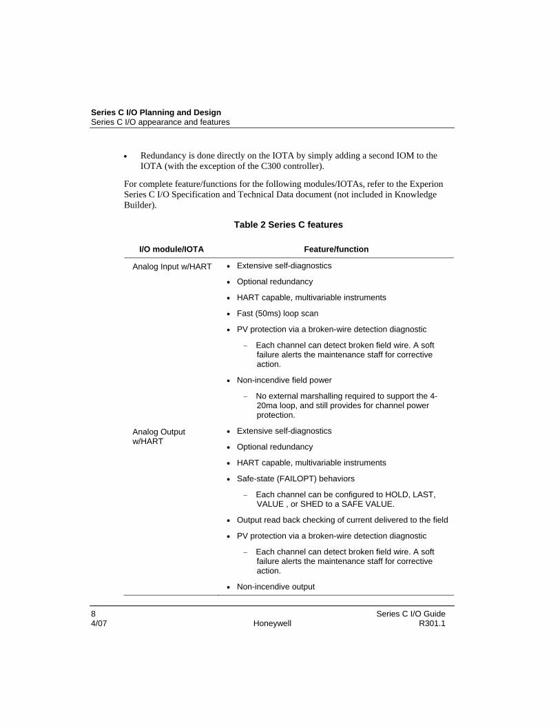
• Redundancy is done directly on the IOTA by simply adding a second IOM to the IOTA (with the exception of the C300 controller).
For complete feature/functions for the following modules/IOTAs, refer to the Experion Series C I/O Specification and Technical Data document (not included in Knowledge Builder).
Table 2 Series C features
I/O module/IOTA Feature/function
Analog Input w/HART • Extensive self-diagnostics
• Optional redundancy
• HART capable, multivariable instruments
• Fast (50ms) loop scan
• PV protection via a broken-wire detection diagnostic
− Each channel can detect broken field wire. A soft failure alerts the maintenance staff for corrective action.
• Non-incendive field power
− No external marshalling required to support the 4-20ma loop, and still provides for channel power protection.
Analog Output w/HART
• Extensive self-diagnostics
• Optional redundancy
• HART capable, multivariable instruments
• Safe-state (FAILOPT) behaviors
− Each channel can be configured to HOLD, LAST, VALUE , or SHED to a SAFE VALUE.
• Output read back checking of current delivered to the field
• PV protection via a broken-wire detection diagnostic
− Each channel can detect broken field wire. A soft failure alerts the maintenance staff for corrective action.
• Non-incendive output

Series C I/O appearance and features New look and feel
Series C I/O Guide 9 R301.1 Honeywell 4/07
I/O module/IOTA Feature/function
− No external marshalling required to support the 4-20ma loop, and still provides for channel power protection.
Digital Input 24VDC • Extensive self-diagnostics
• IOM redundancy
• Input direct/reverse
• Internal or external field power selections
• Galvanic isolation
• PV protection via a broken-wire detection diagnostic
− Each channel can detect broken field wire. A soft failure alerts the maintenance staff for corrective action.
• Non-incendive output
− No external marshalling required to support the 4-20ma loop, and still provides for channel power protection.
Direct Input High Voltage
• Extensive self-diagnostics
• Functional redundancy
• Input direct/reverse
• Galvanic isolation
Direct Output bussed 24Vdc
• Extensive self-diagnostics
• Functional redundancy
• Output direct/reverse
• Safe-state (FAILOPT) behaviors
− Each channel can be configured to HOLD, LAST, VALUE, or SHED to a SAFE VALUE.
• Fuse-less short circuit protection allows a short circuit to exist without blowing any fuses. When a particular channel is shorted, internal circuits detect this and remove power to the field connection. The channel remains de-energized until the short circuit is repaired

Series C I/O Planning and Design Series C I/O and C300 topology
10 Series C I/O Guide 4/07 Honeywell R301.1
I/O module/IOTA Feature/function
• Latched, pulsed or pulse-width modulated output
• Galvanic isolation
• Output read back checking to screw terminal
Digital Output – Relay IOTA
• Galvanic isolation
• Counter EMF snubbing circuit
• Isolated dry contact (Form A or B)
• Output read back checking on system side of driver
Low Level Analog (temperature) Input - LLMUX
• TC and RTD operation
• Remote cold junction capability
• 1 Second PV scanning with OTD protection
• Configurable OTD protection (See below)
• Temperature points can be added in 16 point increments
Series C I/O and C300 topology Series C I/O can be attached to an IOLINK that is being mastered by a C300 controller. It is important to note that:
• IOLink - Serves as data repository for IOM function blocks in Control Builder to provide communications interface with Series C I/O.
• Series C I/O cannot reside on an IOLINK mastered by an IOLIM or xPM.

Series C I/O and C300 topology New look and feel
Series C I/O Guide 11 R301.1 Honeywell 4/07
Figure 1 Series C I/O and C300 topology
Series C I/O Planning and Design Series C I/O and C300 topology
12 Series C I/O Guide 4/07 Honeywell R301.1
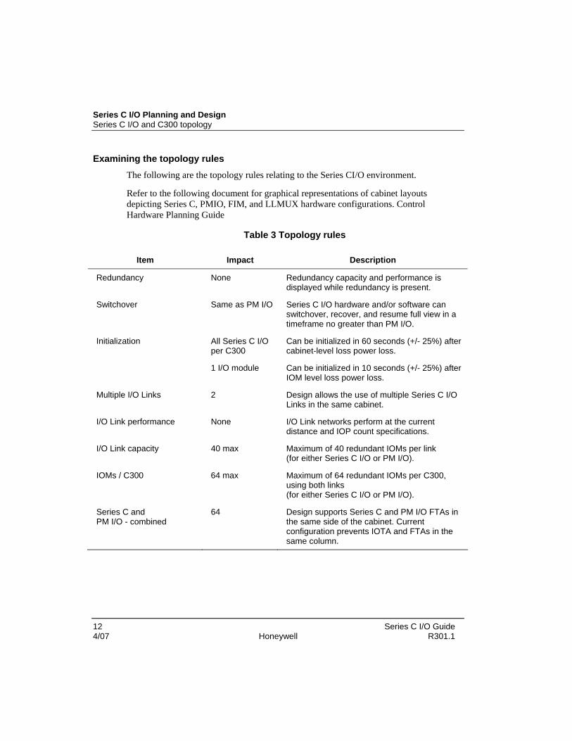
Examining the topology rules The following are the topology rules relating to the Series CI/O environment.
Refer to the following document for graphical representations of cabinet layouts depicting Series C, PMIO, FIM, and LLMUX hardware configurations. Control Hardware Planning Guide
Table 3 Topology rules
Item Impact Description
Redundancy None Redundancy capacity and performance is displayed while redundancy is present.
Switchover Same as PM I/O Series C I/O hardware and/or software can switchover, recover, and resume full view in a timeframe no greater than PM I/O.
Initialization All Series C I/O per C300
Can be initialized in 60 seconds (+/- 25%) after cabinet-level loss power loss.
1 I/O module Can be initialized in 10 seconds (+/- 25%) after IOM level loss power loss.
Multiple I/O Links 2 Design allows the use of multiple Series C I/O Links in the same cabinet.
I/O Link performance None I/O Link networks perform at the current distance and IOP count specifications.
I/O Link capacity 40 max Maximum of 40 redundant IOMs per link (for either Series C I/O or PM I/O).
IOMs / C300 64 max Maximum of 64 redundant IOMs per C300, using both links (for either Series C I/O or PM I/O).
Series C and PM I/O - combined
64 Design supports Series C and PM I/O FTAs in the same side of the cabinet. Current configuration prevents IOTA and FTAs in the same column.

Supported Series C I/O modules Available Series C I/O modules
Series C I/O Guide 13 R301.1 Honeywell 4/07
Supported Series C I/O modules Available Series C I/O modules
The list of I/O modules below can be used on a Series C IOLINK. The IOLINK contains a function that enables programming and reprogramming the executable image (rather than substitution of a removable hardware component). The preferred method of delivery of the image is over the IOLink.
TIP
Series C IOLINK cannot contain any PM I/O IOPs.
C300 IOLINK block parameter IOLINKTYPE is used to determine if the IOLINK supports either Series C I/O or PM I/O.
Table 4 Available I/O modules
IOM model names
IOM block name
Description # of chnls
Similar to PMIO type
IOP model names
CU-PAIH01 CC-PAIH01
AI-HART High Level Analog Input with HART
16 HLAIHART MU-PHAI01 MC-PHAI01
CU-PAIM01 CC-PAIM01
AI-LLMUX see note 1
Low Level Analog Input Mux
64 LLMUX MU-PLAM02 MC-PLAM02
CU-PAOH01 CC-PAOH01
AO-HART Analog Output with HART
16 AO16HART MU-PHAO01 MC-PHAO01
CC-PDIH01 DI-HV see note 2
High Voltage Digital Input (IOM supports both 120 and 240 volts AC)
32 DI MU-PDIX02 MC-PDIX02
CC-PDIL01 DI-24 Low Voltage Digital Input (24 volts DC)
32 DI or DI24V
MU-PDIX02 MC-PDIX02 MU-PDIY22 MC-PDIY22
CC-PDOB01 DO-24B see note 3
Bussed Low Voltage Digital Output (24 volts DC)
32 DO_16 or DO_32
MU-PDOX02 MC-PDOX02 MU-PDOY22 MC-PDOY22

Series C I/O Planning and Design Supported Series C I/O modules
14 Series C I/O Guide 4/07 Honeywell R301.1
Notes: 1. Only available as non-redundant IOM 2. Capable of 125 volts DC, all 32 channels can be used 3. Used with Bussed or Relay IOTAs
Identifying supported Series C I/O modules The Series C I/O model designations follow a “CX-YZZZSNN” format.
Where:
• C is for the Series C (critical I/O) Product Line. The model number for every product begins with a “C” designation for Series C.
• X is either U or C (U = Standard Assembly and C = Corrosion Protected Assembly)
• Y is either P, C, T, G, H, S, F, PW, K, E or M
− P = I/O Module
− C = Control Processor
− T = Termination Assembly
− G = GI/IS Termination Assembly
− H = Hazardous Interface
− S = Custom Interface
− F = FTE
− PW = Power
− K = Cabling
− E = Enclosure
− M = Mechanical
• ZZZ is a particular function or model.
• NN is a series of model and can also can be used as additional model information - NN +10 = Redundant complement to an IOTA.

Supported Series C I/O options Available Series C I/O options
Series C I/O Guide 15 R301.1 Honeywell 4/07
Supported Series C I/O options Available Series C I/O options
The following Series C I/O options are supported in Experion.
• I/O Redundancy
• Power Supply Redundancy
• HART Communications
• Corrosion Protection
Inspecting the Series C I/O library Series C I/O Module function blocks and I/O Channel blocks are housed in the Series C I/O library of Control Builder.
Figure 2 Series C I/O library

Series C I/O Planning and Design Supported Series C I/O options
16 Series C I/O Guide 4/07 Honeywell R301.1
Inspecting IOM function blocks
TIP
Experion can not logically distinguish between coated and uncoated IOMs.
For example: the IOM block name AI-HART is used for the coated and uncoated HART capable analog input IOM.
All IOM function blocks are associated with (children of) an IOLINK function block.
The Series C I/O IOM function blocks are the following:
• AI-HART
• AI-LLMUX
• AO-HART
• DI-24
• DI-HV
• DO-24B Inspecting channel function blocks
The Series C I/O Channel function blocks are the following:
• AICHANNEL
• AOCHANNEL
• DICHANNEL
• DOCHANNEL
Defining module containment An individual channel within a Series C I/O block is often abbreviated as an IOC block. While an IOC block must be “contained in” a Control Module (CM) in Control Builder, the IOC block actually resides within the associated IOM device. This means you change the execution state (EXECSTATE) of a CM independent of the IOC’s point execution state (PTEXECST).

Supported Series C I/O options Defining module containment
Series C I/O Guide 17 R301.1 Honeywell 4/07
Figure 3 Execution State
Figure 4 Point Execution State

Series C I/O Planning and Design I/O Link performance specifications
18 Series C I/O Guide 4/07 Honeywell R301.1
I/O Link performance specifications The concept of a Link Unit (LU) was introduced with PM I/O where a LU was defined as being roughly equivalent to one parameter read (or write) per second.
With the introduction of Series C I/O, the transmission rate of data on an IOLINK configured with Series C I/O is now double that of PM I/O.
Table 5 Transmission rate of data on an I/O Link
I/O type Link rate per second Link Units per second
PM I/O 1 parameter read or write 1000
Series C I/O 1 parameter read or write 2000
TIP
If your configuration exceeds 2000 LUs on a Series C I/O IOLINK, then an I/O Link Access Overrun can occur. This type of overrun occurs when parameter reads and writes are not completed within their cycle time. This indicates too many parameter access requests were attempted through the I/O Link.
The IOLINK function block generates a “439, IOLINK Process Data collection Overrun” alarm when an I/O Link overrun occurs.
Reviewing Link Unit utilization
The Link Unit utilization cycle rate varies depending on the type of block being used. The following table defines the specifications for the various blocks.
Table 6 Link Unit utilization rates
Block names Data processing Link Units per cycle time
Cycle time
Every primary IOM Event Collection 1 500 ms
Every secondary IOM Event Collection 1 500 ms
DI-xxx IOM blocks PV Scanning 1.75 IOM block’s SCANRATE
DO-xxx IOM blocks BACKCALC Scanning 1.25 IOM block’s SCANRATE

I/O Link performance specifications Reducing I/O Link traffic
Series C I/O Guide 19 R301.1 Honeywell 4/07
Block names Data processing Link Units per cycle time
Cycle time
AI-xxx IOM blocks PV Scanning 5 IOM block’s SCANRATE
AO-xxx IOM blocks BACKCALC Scanning 5 IOM block’s SCANRATE
AOCHANNEL OP Store 1 OP connector’s CM Execution Rate
status output for DOCHANNEL
SO Store 1 SO connector’s CM Execution Rate
Pulse width modulation for DOCHANNEL
BACKCALC Scanning 1 IOM block’s SCANRATE
Pulse width modulation for DOCHANNEL
OP Store 1 OP connector’s CM Execution Rate
Reducing I/O Link traffic
If I/O Link overruns persist, you reduce the I/O Link traffic by:
• Increasing the value of the IOM’s Scanning Rate parameter [SCANRATE] (i.e. increasing the time interval between IOM scans)
• Increase the Execution Period of Control Modules containing Output Channel blocks
• Reducing the number of IOMs configured
• Split the IOMs across multiple IOLINKS
TIP
Link IDs are only detected on their corresponding modules.
• Modules with Link ID 1 cannot detect Link ID 2.
• Modules with Link ID 2 cannot detect Link ID 1. Event collection
Under normal conditions, every IOM configured on the I/O Link, whether primary or secondary, uses Link Units for event collection. This activity is periodic and can be accounted for, however; conditions in which numerous events and alarms are generated

Series C I/O Planning and Design I/O Link performance specifications
20 Series C I/O Guide 4/07 Honeywell R301.1
are unpredictable and may cause transient I/O Link overruns and delays in display updates. These transient overruns clear once the rush of events and alarms are collected.
PV and Back calculation scanning The following I/O parameters are automatically scanned by the C300 as soon as the IOM block is loaded.
Table 7 I/O parameters scanned when the IOM is loaded
IOM block Scanned parameters
AI-xxx PV, PVSTS
AO-xxx OP, INITREQ
DI-xxx PVFL, BADPVFL
DO-xxx SO, INITREQ, OP
The number of AI and DI channel blocks contained within CMs or SCMs:
• does not increase LU consumption.
The DO channel blocks contained in CMs and SCMs:
• does also not increase LU consumption for Back Calculation scanning, but LU consumption increases for each OP or SO store.
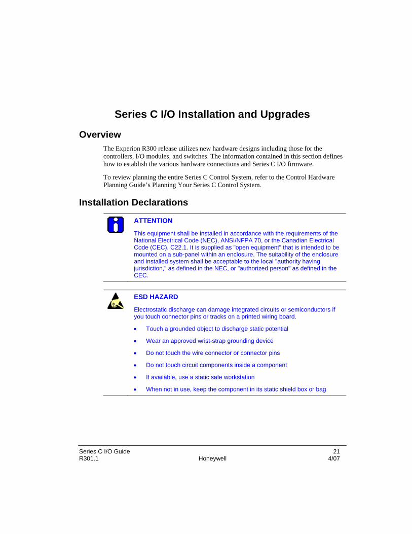
Series C I/O Guide 21 R301.1 Honeywell 4/07
Series C I/O Installation and Upgrades
Overview The Experion R300 release utilizes new hardware designs including those for the controllers, I/O modules, and switches. The information contained in this section defines how to establish the various hardware connections and Series C I/O firmware.
To review planning the entire Series C Control System, refer to the Control Hardware Planning Guide’s Planning Your Series C Control System.
Installation Declarations
ATTENTION
This equipment shall be installed in accordance with the requirements of the National Electrical Code (NEC), ANSI/NFPA 70, or the Canadian Electrical Code (CEC), C22.1. It is supplied as "open equipment" that is intended to be mounted on a sub-panel within an enclosure. The suitability of the enclosure and installed system shall be acceptable to the local "authority having jurisdiction," as defined in the NEC, or "authorized person" as defined in the CEC.
ESD HAZARD
Electrostatic discharge can damage integrated circuits or semiconductors if you touch connector pins or tracks on a printed wiring board.
• Touch a grounded object to discharge static potential
• Wear an approved wrist-strap grounding device
• Do not touch the wire connector or connector pins
• Do not touch circuit components inside a component
• If available, use a static safe workstation
• When not in use, keep the component in its static shield box or bag

Series C I/O Installation and Upgrades Installation Declarations
22 Series C I/O Guide 4/07 Honeywell R301.1
WARNING
Unless the location is known to be non-hazardous, do not:
• Connect or disconnect cables
• Install or remove components
while the control system is powered. Introduction
The following figure represents the main cabling of the Series C300 controller, Control Firewall, and I/O IOTA boards.

Installation Declarations Introduction
Series C I/O Guide 23 R301.1 Honeywell 4/07
Figure 5 Series C board connections

Series C I/O Installation and Upgrades Installation Declarations
24 Series C I/O Guide 4/07 Honeywell R301.1
Cabling The following graphic is an example of possible configuration connections with regards to the Series C I/O cabinet. Your configuration may vary based on the module layout of your cabinet. The following table defines cable type and usage in the graphic below.
Table 8 Series C I/O cable types
Cable Color Purpose
FTE -A Yellow Connect controller to firewall (point-to-point)
FTE - B Green Connect controller to firewall (point-to-point)
FTE - Redundant Orange Private path between primary and secondary controller (point-to-point)
IOL1A Grey/yellow Connect controller to I/O
IOL1B Grey/green Connect controller to I/O
IOL2A Violet/yellow Connect primary controller to secondary controller and then to I/O
IOL2B Violet/green Connect primary controller to secondary controller and then to I/O

Installation Declarations Cabling
Series C I/O Guide 25 R301.1 Honeywell 4/07
Figure 6 Series C cabling

Series C I/O Installation and Upgrades Installing the IOTA onto the carrier
26 Series C I/O Guide 4/07 Honeywell R301.1
Installing the IOTA onto the carrier Prerequisites Carrier for mounting IOTA is installed in a cabinet or desired mounting location.
• Power supply is installed.
• Control firewall is installed.
• All wiring and pre-fabricated cables are available and labeled as applicable.
• Be sure all power is turned off at the installation location.
• You have the mounting hardware supplied with the components.
Considerations You can use a redundant IOTA to support a non-redundant Series C IOM application. Just be sure to install the non-redundant Series C IOM in the primary location on the IOTA.
Be sure the enclosure is connected to a protective earth ground using #8 AWG solid copper wire. There should be metal to metal contact between the grounding bus bar and the enclosure as well as the carrier.
Mounting the IOTA
Step Action
1 Select desired mounting location on carrier and align mounting holes in IOTA with screw-hole locations on the carrier.
6 inch IOTA board 4 mounting screws
12 inch IOTA board 6 mounting screws
When mounting the 12 inch IOTA board, it is recommended to:
• secure the three mounting screws on one side (either left or right) and then secure the other side
• NOTE: Securing the four corner screws and the two middle screws may cause bowing of the board and impact the alignment of the IOTA board to the carrier holes and is not recommended.
2 Be sure component side of IOTA is facing up. Secure IOTA to carrier using screws, washers and spacers provided. Insert spacers and washers between bottom of IOTA and top of carrier.

Installing the IOTA onto the carrier Mounting the IOTA
Series C I/O Guide 27 R301.1 Honeywell 4/07
Step Action
3 This completes the procedure.

Series C I/O Installation and Upgrades Replacing an I/O IOTA
28 Series C I/O Guide 4/07 Honeywell R301.1
Replacing an I/O IOTA
ATTENTION
This procedure can only be performed while off process.
Step Action
1 On the defective IOTA, loosen the screws at each side of the plastic cover that secures the I/O module to the IOTA board. Remove I/O module from the IOTA board and connector.
2 To remove 24 V power to the IOTA board do the following:
• Remove the screw from the left side of the IOTA board that connects to the 24 Vdc bus bar.
• Remove the screw from the right side of the IOTA board that connects to the GND bus bar.
3 Label and disconnect all cables from the IOTA board connectors.
4 Remove the screws that secure the IOTA board to the carrier and remove the IOTA board.
5 Mount new I/O IOTA board on the carrier at the same position as the old IOTA board. Secure with screws.
6 • Reconnect your cables (removing labels if they were utilized) to the IOTA connectors
7 To reconnect power to the IOTA board via the GND and 24 Vdc bus bars, do the following:
• Install screw through right side of IOTA board to tap into the GND bus bar of carrier.
• Install screw through left side of IOTA board to tap into the 24 V bus bar of carrier.
8 Insert the I/O module onto IOTA board making sure that the I/O circuit board mates properly with the IOTA board connector.
Secure the I/O module to the IOTA board with two screws located at each side of the plastic cover.
9 The I/O module will boot-up into IDLE state.

Mounting the I/O module onto the IOTA Prerequisites
Series C I/O Guide 29 R301.1 Honeywell 4/07
Step Action
10 In Control Builder, perform a ‘Load with Contents’.
Mounting the I/O module onto the IOTA Prerequisites
It is recommended to attach the IOTA board to the carrier prior to mounting the module to the IOTA. The following also needs to be established:
• IOTA mounted on the carrier rack
• Power supply is installed.
• Control firewall is installed.
• All wiring and pre-fabricated cables are available and labeled as applicable.
• Be sure all power is turned off at the installation location.
• You have the mounting hardware supplied with the components.
Mounting the module
Step Action
1 Insert the module onto IOTA board making sure that the circuit board mates properly with the IOTA board connector.
2 Secure the module to the:
• IOTA board - with two screws located at each side of the plastic cover.
• Carrier - with the long screw that is inserted into the hole on the face of the module’s plastic cover.
3 This completes the procedure.

Series C I/O Installation and Upgrades Replacing an I/O module
30 Series C I/O Guide 4/07 Honeywell R301.1
Replacing an I/O module
CAUTION
We recommend that you proceed with extreme caution whenever replacing any component in a control system. Be sure the system is offline or in a safe operating mode.
Component replacements may also require corresponding changes in the control strategy configuration through Control Builder, as well as downloading appropriate data to the replaced component.
Prerequisites
You have logged onto Control Builder with sufficient security level to make control strategy changes.
Considerations • You can remove and install the Series C IOM under power.
• Be sure you take ESD hazard precautions when handling the Series C FIM and IOTA.
To replace an I/O module
Step Action
1 Loosen screws at each side of the plastic cover that secures the I/O module to the IOTA board. Remove the I/O module from the IOTA board and connector.
2 Insert the new I/O module onto IOTA board making sure that the I/O circuit board mates properly with the IOTA board connector.
Secure the I/O module to the IOTA board with two screws located at each side of the plastic cover.
3 The new I/O module will boot-up to the IDLE state.
4 Load firmware which is the same version as was running in the old controller.
5 In Control Builder, perform a ‘Load with Contents”.

Grounding and power considerations - IOTA boards Attaching the IOTA board
Series C I/O Guide 31 R301.1 Honeywell 4/07
Grounding and power considerations - IOTA boards Attaching the IOTA board
The Series C cabinet allows mounted carriers that support the attachment of the IOTA boards. By making these connections, power and chassis grounding is provided to the IOTA board.
Testing for power
CAUTION
Extreme care should be taken when testing for power at the Series C bus bars. Improper testing can result in an electrical short which will impact all modules attached to the channel carrier assembly.
Never use a test probe at an unattached IOTA’s 24V screw hole. The probe can potentially touch the back channel assembly causing a short.
The following locations are recommended for testing power:
Preferred location if IOTAs are attached
• Center of the screw that attaches the IOTA to the 24V bus bar.
Preferred location if IOTAs are NOT attached.
• Center of the screw of top connection terminal for power cable.

Series C I/O Installation and Upgrades Grounding and power considerations - IOTA boards
32 Series C I/O Guide 4/07 Honeywell R301.1
Testing for power at IOTA screw
Refer to the Caution above at Testing for power
Step Action
1 Insert the test probe at the center of the screw that attaches the IOTA to the 24V power connection.
2 This concludes this procedure.
Testing for power at 24V bus bar top terminal Refer to Caution above at Testing for power.
Step Action
1 Carefully pull the red cap from the top of the terminal. It remains attached to the power cable.
2 Insert the test probe at the center of the screw to the 24V power terminal.
3 Replace the red cap.
4 This concludes this procedure.

Grounding and power considerations - IOTA boards Testing for power
Series C I/O Guide 33 R301.1 Honeywell 4/07
Figure 7 Grounding and power connections

Series C I/O Installation and Upgrades Connecting IOMs and field devices via I/O Termination Assemblies
34 Series C I/O Guide 4/07 Honeywell R301.1
Connecting IOMs and field devices via I/O Termination Assemblies IOTAs wiring diagrams
All connections between IOMs and field devices are via I/O Termination Assemblies (IOTAs). IOTAs are sometimes connected to ancillary hardware that pre-conditions the signal for use in Experion.
The following table defines the relationship between IOM type and the ancillary hardware.
Table 9 IOM types and ancillary hardware
If IOM type is Then the ancillary hardware
DO Digital Output
takes the output signal and drives a set of relays
AI LLMUX can be one to four Field Termination Assemblies.
These FTA’s pre-condition and package the signals before they are received by the IOTA.
To simplify system hardware selection and to minimize spare parts requirements, IOMs can be used with various types of IOTAs. The following table provides a list of IOMs, their associated IOTAs, and ancillary hardware. All IOM models listed within the same cell can be installed on any of the IOTAs listed in the adjacent cell.
Table 10 IOMs, IOTAs, and ancillary cards IOM block
type IOM model
number IOTA model
number IOTA description IOTA
supported FTAs or
ancillary cards
CU-TAIX01 AI, non-redundant, non-coated
None CU-PAIH01
CU-TAIX11 AI, redundant, non-coated None
CC-TAIX01 AI, non-redundant, coated None
AI-HART
CC-PAIH01
CC-TAIX11 AI, redundant, coated None

Connecting IOMs and field devices via I/O Termination Assemblies IOTAs wiring diagrams
Series C I/O Guide 35 R301.1 Honeywell 4/07
IOM block type
IOM model number
IOTA model number
IOTA description IOTA supported
FTAs or ancillary cards
MU-TAMT04
MU-TAMR04
CU-PAIM01 CU-TAIM01 (note 1)
LLMUX, non-redundant, non-coated
MU-TAMT14
MC-TAMT04
MC-TAMR04
AI-LLMUX
CC-PAIM01 CC-TAIM01 (note 1)
LLMUX, non-redundant, coated
MC-TAMT14
CU-TAOX01 AO, non-redundant, non-coated
None CU-PAOH01
CU-TAOX11 AO, redundant, non-coated None
CC-TAOX01 AO, non-redundant, coated None
AO-HART
CC-PAOH01
CC-TAOX11 AO, redundant, coated None
CC-TDI120 DI, High Voltage, non-coated
None
CC-TDI130 DI, High Voltage, non-coated
None
CC-TDI240 DI, High Voltage, non-coated
None
CC-TDI250 DI, High Voltage, non-coated
None
CC-TDI120 DI, High Voltage, coated None
CC-TDI130 DI, High Voltage, coated None
CC-TDI240 DI, High Voltage, coated None
DI-HV CC-PDIH01
CC-TDI250 DI, High Voltage, coated None
CC-TDIL01 DI-24V, non-redundant, non-coated
None DI-24 CC-PDIL01
CC-TDIL11 DI-24V, redundant, non-coated
None

Series C I/O Installation and Upgrades Connecting IOMs and field devices via I/O Termination Assemblies
36 Series C I/O Guide 4/07 Honeywell R301.1
IOM block type
IOM model number
IOTA model number
IOTA description IOTA supported
FTAs or ancillary cards
CC-TDIL01 DI-24V, non-redundant, coated
None
CC-TDIL11 DI-24V, redundant, coated none
CC-TDOB01 DO-24V, bussed, non-redundant, non-coated
None
CC-TDOB11 DO-24V, bussed, redundant, non-coated
None
CC-TDOR01 DO- High Voltage Relay, non-redundant, non-coated
CC-SD0R01 (note 2)
CC-TDOR11 DO- High Voltage Relay, redundant, non-coated
CC-SD0R01 (note 2)
CC-TDOB01 DO-24V, bussed, non-redundant, coated
None
CC-TDOB11 DO-24V, bussed, redundant, coated
None
CC-TDOR01 DO- High Voltage Relay, non-redundant, coated
CC-SD0R01 (note 3)
DO-24B CC-PDOB01 (note 4)
CC-TDOR11 DO- High Voltage Relay, redundant, coated
CC-SD0R01 (note 3)
NOTES
1. Cx-TAIM01 - This DOES NOT require the MU-TLPA02 Power Adapter and supports in-cabinet configuration or in a suitable enclosure up to 1,000 feet remote from the LLMUX IOTA as shown in Figure 15. There is the restriction that the interconnecting cabling between the IOTA and the FTAs must be routed in a manner consistent with national and local electrical code requirements for the environment (Division 2/Zone 2 hazardous location or nonhazardous location) in which it is routed.
2. One CU-KREBxx uncoated cable is used to connect the IOTA to the relay extension board.
3. One CC-KREBxx coated cable is used to connect the IOTA to the relay extension board.

Connecting IOMs and field devices via I/O Termination Assemblies IOTAs wiring diagrams
Series C I/O Guide 37 R301.1 Honeywell 4/07
4. Bussed IOM (PDOB01) is used for both bussed outputs and relay outputs, however, only relay outputs require the additional card.
The following issues should be noted when considering connections:
• redundant configured IOMs must be installed on a redundant IOTA
• non-redundant IOMs can be installed on non-redundant and redundant IOTAs. However, when installed on a redundant IOTA, non-redundant IOMs must be installed in the upper IOM slot of the redundant IOTA

Series C I/O Installation and Upgrades Powering the Series C system
38 Series C I/O Guide 4/07 Honeywell R301.1
Powering the Series C system Supplying power to I/O modules
Power systems for the Series C control hardware provides:
• optional redundant power supplies with separate mains power feeds
• optional system battery backup is also available, and
• a memory RAM battery is provided to supply memory retention power for the C300 Controller
The capabilities and options available with the Series-C power system are very similar to those available with the Process Manager Power System.
Refer to the Series C Power Supply in the C300 Controller User Guide additional power system information.

Fusing – IOTA boards Protecting the Series C I/O components
Series C I/O Guide 39 R301.1 Honeywell 4/07
Fusing – IOTA boards Protecting the Series C I/O components
Series-C I/O modules are constructed to support normal field failures, wiring errors and conditions such as a shorted wire. All Series-C IOTAs contain at least one fuse that provide protection for catastrophic errors in the IOTA, IOM and other elements of the Series-C system. In normal operation as well as many abnormal operations, the fuse element should not blow.
The following attributes apply to all Series-C I/O modules:
• 24V DC power is protected by a fuse mounted on the IOTA.
• All low power modules allow for a minimum injected voltage of 30V DC.
• For redundant IOTAs, a fuse is provided for each IOM. If one fuse element were to blow, the partner IOM continues to operate.
ATTENTION
In virtually all instances of normal field failure, the I/O module will recover without any maintenance action such as replacing a component or fuse.
To access the parts information for the fuses associated with each board and module, , refer to Fuse information in the Recommended Spare Parts section.

Series C I/O Installation and Upgrades IOTA pinouts
40 Series C I/O Guide 4/07 Honeywell R301.1
IOTA pinouts Field wiring
All I/O field terminations accept up to 14ga stranded wire.
Analog Input IOTA Models CU/CC-TAIX01, CU/CC-TAIX11
The Series C Analog Input IOTA board is represented by the following information and graphic.
To access the parts information for the:
• module
• IOTA
• terminal plug-in assembly, and
• fuses
associated with this board and module, refer to Analog Input in the Recommended Spare Parts section.

IOTA pinouts Analog Input IOTA
Models CU/CC-TAIX01, CU/CC-TAIX11
Series C I/O Guide 41 R301.1 Honeywell 4/07
Series C Analog Input 6 inch, non-redundant IOTA is shown.
Figure 8 Series C Analog Input 6 inch, non-redundant IOTA
To properly wire your module to the Series C Analog Input IOTA board with terminal block 1 (TB1) and terminal block 2 (TB2), use the following tables.
Table 11 AI 6 inch, non-redundant – terminal block 1
Terminal block 1
Channel Return screw Power screw
Channel 1 2 1

Series C I/O Installation and Upgrades IOTA pinouts
42 Series C I/O Guide 4/07 Honeywell R301.1
Terminal block 1
Channel Return screw Power screw
Channel 2 4 3
Channel 3 6 5
Channel 4 8 7
Channel 5 10 9
Channel 6 12 11
Channel 7 14 13
Channel 8 16 15
Channel 9 18 17
Channel 10 20 19
Channel 11 22 21
Channel 12 24 23
Channel 13 26 25
Channel 14 28 27
Channel 15 30 29
Channel 16 32 31
Table 12 AI 6 inch, non-redundant – terminal block 2
Terminal block 2 – Low side of the differential inputs
If this TB2 screw is
used
Then this channel is used
And this jumper
is clipped
1 13 JP17
2 14 JP18
3 15 JP19
4 16 JP20
In the example below, cutting J20 would configure channel 16 for differential operation and pin 4 would be the low side (-) of the input signal.

IOTA pinouts Analog Input IOTA
Models CU/CC-TAIX01, CU/CC-TAIX11
Series C I/O Guide 43 R301.1 Honeywell 4/07
Terminal block 2 – Low side of the differential inputs
If this TB2 screw is
used
Then this channel is used
And this jumper
is clipped
Refer to Custom wiring for additional power connection possibilities.
Jumpers are utilized to support the following conditions:
Table 13 Jumpers to support Analog Input connections
Channels Signal screw

Series C I/O Installation and Upgrades IOTA pinouts
44 Series C I/O Guide 4/07 Honeywell R301.1
Channels Signal screw
For channels 1 through 12
Each channel (1 through 12):
• has a corresponding jumper. Therefore, channel 1’s jumper would be JP1, and so forth.
• the jumper would be cut if connected to voltage transmitters (1-5v. etc.)

IOTA pinouts Analog Input wiring
Series C I/O Guide 45 R301.1 Honeywell 4/07
Channels Signal screw
For channels 13 through 16
Each channel 13 through 16:
• has a corresponding jumper. Therefore, channel 13’s jumper would be JP13, and so forth.
• the jumper would be cut if connected to voltage transmitters (1-5v. etc.)
Jumpers J17 through J20 are used with Terminal Block 2 (TB2) and are used if the device is grounded in the field.
Analog Input wiring
Field wiring and module protection
Individual field wiring is protected by an internal protection circuit permitting:
• Short circuit protection of input for field short circuits. Protection suitable for Division 2 non-incendive / Zone 2 non-arcing.
• Each signal can be shorted in the field with no damage to module or board. Other channels on the same IOM will not be affected

Series C I/O Installation and Upgrades IOTA pinouts
46 Series C I/O Guide 4/07 Honeywell R301.1
Two-wire transmitter wiring
The AI IOM/IOTA is optimized for use with classic two-wire transmitters. All 16 channels can accept inputs from two-wire transmitters without any special wiring or jumpering options.
The standard usage is to:
• reserve the first 12 channels of the AI IOM/IOTA for classic two-wire transmitters, and
• use the last 4 channels of the IOM/IOTA to interface any of the supported input styles (including two-wire transmitters).
Depending on the input style applied to channels 13 through 16, you may need to cut jumpers on the IOTA and apply wiring to the TB2 terminal block on the IOTA. This is discussed in detail in the following sections.
Non two-wire transmitter wiring
The IOTA is pre-engineered (without custom wiring) to accept sources that are not two-wire transmitters, but you must use channels 13 through 16.
When sources other than two-wire transmitters are to be interfaced and you have more than 4 per IOTAs, then:
• the first four must be interfaced to channels 13 through 16, and
• the remainder may be able to interface to channels 1 through 12 (depending on input style) but you must perform some degree of custom wiring.
NOTE: There are some input styles that simply cannot be applied to channels 1 through 12 – if that applies to you then you will likely need to purchase an additional IOM/IOTA.
CAUTION The jumpers on the IOTA are non-repairable – once cut, they stay cut.
Careful planning is a must.
Custom wiring
Custom wiring means:
• using additional wires to TB2 (beyond their intended purpose for channels 13 through 16)
• and/or using wires to another termination area in the cabinet engineered on a project-basis.

IOTA pinouts Analog Input wiring
Series C I/O Guide 47 R301.1 Honeywell 4/07
Some of the styles (other than two-wire transmitter):
• can be applied to channels 1 through 12 with the use of custom wiring.
• Other cannot be applied to channels 1 through 12 at all.
Table 14 Custom wiring to support Analog Input
Custom wiring scenarios
Self-powered transmitter with EPKS system ground
It is recommended to use channels 13 through 16, since these channels have a dedicated Series C ground screw (although it is possible to use channels 1 through 12).
For the following example:
• Channel 13 is used
• No jumpers need to be cut.
• The wire-pair is terminated to TB1-26 and TB2-1
• TB1-25 is not used.
Optional Self Powered XMTR(also supplies loop power)
external power
(system ground)
145Ω+24VDC
4-20 MAR13 = 250Ω
JP13
TB1-25
TB1-26
JP17TB2-1

Series C I/O Installation and Upgrades IOTA pinouts
48 Series C I/O Guide 4/07 Honeywell R301.1
Custom wiring scenarios
Self-powered transmitter with device grounded
This case can only be applied to channels 13 through 16 and the corresponding jumper must be cut.
For the following example:
• Cutting jumper JP-17 permits the transmitter’s ground to be utilized
− (Series C ground is then not used, since it does not fall within the limits of the common mode tolerated by the AI IOM).
− JP17 through JP20 are for channels 13 through 16, respectively.
• The wire-pair is terminated to TB1-26 and TB2-1.
• TB1-25 is not used.
Optional Self Powered XMTR(also supplies loop power)
external power
(device ground)
145Ω+24VDC
4-20 MAR13 = 250Ω
JP13
TB1-25
TB1-26
JP17TB2-1

IOTA pinouts Analog Input wiring
Series C I/O Guide 49 R301.1 Honeywell 4/07
Custom wiring scenarios
Self-powered 3-wire transmitter (system ground)
It is recommended to use channels 13 through 16, since these channels have 3 screws per channel (although it is possible to use channels 1 through 12).
For the following example:
• Channel 13 is used
• No jumpers need to be cut
• The three-wire-pair is terminated to TB1-25, TB1-26 and TB2-1
4-20 MA
Self Powered 3 Wire XMTR
commonexternal power
145Ω+24VDC
R13 = 250Ω
JP13
TB1-25
TB1-26
JP17TB2-1

Series C I/O Installation and Upgrades IOTA pinouts
50 Series C I/O Guide 4/07 Honeywell R301.1
Custom wiring scenarios
Voltage input (system ground)
It is recommended to use channels 13 through 16, since these channels have a dedicated Series C ground screw (although it is possible to use channels 1 through 12).
For the following example:
• Channel 13 is used.
• Jumper JP13 (for the 250 ohm spool) needs to be cut.
• The wire-pair is terminated to TB1-26 and TB2-1.
• TB1-25 is not used.
Votage Output Transducer(system ground)
0-5 VDC
145Ω+24VDC
R13 = 250Ω
JP13
TB1-25
TB1-26
JP17TB2-1
Slidewire
– Series C does not support Slidewire.

IOTA pinouts Analog Input wiring
Series C I/O Guide 51 R301.1 Honeywell 4/07
Custom wiring scenarios
Range spool damage and wire shorting
Jumpers JP1 through JP16 are also used to overcome a damaged range spool (250 ohm dropping resistor).
A range spool can be damaged by being directly connected across a 24V for an extended period, such as, taking an even numbered terminal from TB1 to 24V. It can be removed from the circuit by clipping the corresponding jumper. You can continue to use the channel by providing a discrete (axial lead) 250 ohm resistor.
Example: using channel 5 and overcoming a damaged spool
1. One lead of the resistor connects to the even numbered screw on TB1 associated with that channel. (i.e. screw N = 2 times channel M, so screw 10 is for channel 5).
2. The other lead of the resistor connects to Series C ground which can probably be found on any of the TB2 screw positions (assuming the corresponding jumper JP17-20 is still installed).
If TB2 is already filled with wiring, “doubling up” is permitted as long as the total wire dimension is less than the 14 AWG equivalent dimension.
3. Transmitter power is supplied in a non-incendive fashion via the odd-numbered terminals on TB1. This is done via a 145 ohm resistor inline with a Positive Temperature Coefficient (PTC) device that acts like a fuse (but never needs replacement).
Thus these field terminals can be permanently shorted to ground without damage. This is an improvement over Process Manager due to the inclusion of the PTC device.
Analog Input wiring reference table
The following table summarizes the possible Analog Input wiring connections.
Table 15 Summary – Analog Input wiring connections Input style Connection characteristics
Standard 2-wire transmitter − Can use any of the 16 channels.
− No custom wiring required.
− No jumper cuts required.

Series C I/O Installation and Upgrades IOTA pinouts
52 Series C I/O Guide 4/07 Honeywell R301.1
Input style Connection characteristics
Standard self-powered transmitter − Can use any of the 16 channels.
− No custom wiring required.
− No jumper cuts required.
Self-powered transmitter with loop power(system ground)
− Can use any of the 16 channels.
− Custom wiring is required for channels 1-12: you must find a screw terminal at Series C ground for one leg of the transmitter.
− No jumper cuts required
Self-powered transmitter with loop power (device ground)
− Cannot use channels 1-12.
− Only use channels 13-16.
Self-powered 3-wire transmitter (system ground)
− Can use any of the 16 channels.
− Custom wiring is required for channels 1-12: you must find a screw terminal at Series C ground for one leg of the transmitter.
− No jumper cuts required
Voltage Input (system ground) − Can use any of the 16 channels.
− Custom wiring is required for channels 1-12: you must find a screw terminal at Series C ground for one leg of the transducer.
− You must cut the jumper associated with the range spool.
Voltage Input (device ground) − Cannot use channels 1-12.
− Only use channels 13-16.
Note: If multiple instruments need a ground reference the four positions of TB2 can serve as those ground points (assuming the JP17-JP20) jumpers are intact. If more than four grounding screws are needed then a custom wire from TB2 to a separate terminal block can allow for more grounding screw positions.

IOTA pinouts Analog Input wiring
Series C I/O Guide 53 R301.1 Honeywell 4/07
Allowable field wiring resistance
The maximum allowable field wiring resistance between the transmitter and the IOTA connection terminal is dependent upon the voltage requirement of the transmitter. The formula for calculating the max wiring resistance for the Series C Analog Input is given by the following equation.
Rmax = [(13.0 – Vtx) / (0.022)]
where: Vtx = Voltage required at the transmitter terminal
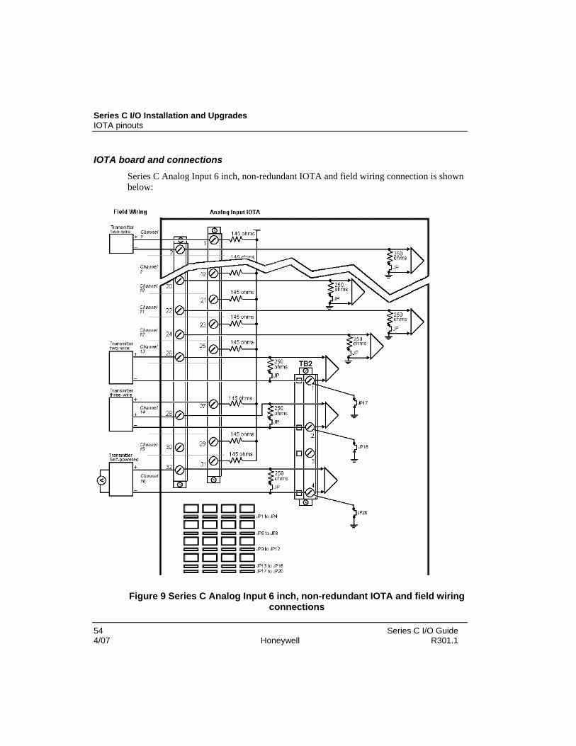
Series C I/O Installation and Upgrades IOTA pinouts
54 Series C I/O Guide 4/07 Honeywell R301.1
IOTA board and connections
Series C Analog Input 6 inch, non-redundant IOTA and field wiring connection is shown below:
Figure 9 Series C Analog Input 6 inch, non-redundant IOTA and field wiring connections

IOTA pinouts Analog Input wiring
Series C I/O Guide 55 R301.1 Honeywell 4/07
Series C Analog Input 12 inch, redundant IOTA is shown:
Figure 10 Series C Analog Input 12 inch, redundant IOTA

Series C I/O Installation and Upgrades IOTA pinouts
56 Series C I/O Guide 4/07 Honeywell R301.1
Analog Output IOTA Models CU/CC-TAOX01, CU/CC-TAOX11
The Series C Analog Output IOTA board is represented by the following information and graphics.
To access the parts information for the:
• module
• IOTA
• terminal plug-in assembly, and
• fuses
associated with this board and module, refer to Analog Output in the Recommended Spare Parts section.
Field wiring and module protection
The Analog Output module provides an output current range of 0ma, and 2.9 ma through 21.1 ma based on the requested Analog Output by the Series-C controller. The output current including the HART modulated signal, does not exceed 22.5mA.
• Short circuit protection of field short circuits. Protection suitable for Division 2 non-incendive / Zone 2 non-arcing..
• Each field wiring pair can be shorted together without damage to the module or IOTA. Other channels in the same module(s) will not be affected.
• A +30 Vdc source can be continuously applied across the OUT+ to OUT- terminals of the IOTA without damage to either module(s) or IOTA (i.e. with the positive lead of the source connected to OUT+ and the negative lead connected to OUT-). To prevent damage to the IOTA surge protection diodes, the current must be limited to 500 mAdc if the source is applied in the reverse polarity (i.e. with the positive lead of the source attached to OUT-, negative lead attached to OUT+). This 500 mAdc restriction does not apply in the positive polarity case.

IOTA pinouts Analog Output IOTA
Models CU/CC-TAOX01, CU/CC-TAOX11
Series C I/O Guide 57 R301.1 Honeywell 4/07
IOTA board and connections Series C Analog Output 6 inch, non-redundant IOTA is shown.
Figure 11 Series C Analog Output 6 inch, non-redundant IOTA

Series C I/O Installation and Upgrades IOTA pinouts
58 Series C I/O Guide 4/07 Honeywell R301.1
To properly wire your module to the Series C Analog Output IOTA board with terminal block 1 (TB1), use the following table.
Table 16 AO 6 inch, non-redundant – terminal block 1
Channel
Return screw (OUT -)
Signal screw (OUT +)
Channel 1 2 1
Channel 2 4 3
Channel 3 6 5
Channel 4 8 7
Channel 5 10 9
Channel 6 12 11
Channel 7 14 13
Channel 8 16 15
Channel 9 18 17
Channel 10 20 19
Channel 11 22 21
Channel 12 24 23
Channel 13 26 25
Channel 14 28 27
Channel 15 30 29
Channel 16 32 31

IOTA pinouts Analog Output IOTA
Models CU/CC-TAOX01, CU/CC-TAOX11
Series C I/O Guide 59 R301.1 Honeywell 4/07
Series C Analog Output 6 inch, non-redundant IOTA and field wiring connection
Figure 12 Series C Analog Output 6 inch, non-redundant IOTA and field wiring connection

Series C I/O Installation and Upgrades IOTA pinouts
60 Series C I/O Guide 4/07 Honeywell R301.1
Series C Analog Output 12 inch, redundant IOTA is shown:
Figure 13 Series C Analog Output 12 inch, redundant IOTA

IOTA pinouts Low Level Analog Input Mux (LLMUX) IOTA
Models CU/CC-TAIM01
Series C I/O Guide 61 R301.1 Honeywell 4/07
Low Level Analog Input Mux (LLMUX) IOTA Models CU/CC-TAIM01
The Series C Low Level Mux IOTA board is represented by the following information and graphics.
To access the parts information for the:
• module
• IOTA
• connector block assembly, and
• fuses
associated with this board and module, refer to Low Level Analog Input in the Recommended Spare Parts section.
Field wiring and module protection
The LLMUX module provides power and communications to up to four Low Level Mux FTAs. Each FTA is protected by a specific fuse. Additionally, a main fuse protects the module’s power path to all FTAs. The following applies to fusing for LLMUX:
Fuse Functionality Description
F1 Power to module electronics
F2 Switched power to all FTAs
FUSE, 1 Amp, 125V, Quick Blo, 5x20mm
F3 Power to FTA 1 only
F4 Power to FTA 2 only
F5 Power to FTA 3 only
F6 Power to FTA 4 only
FUSE, 0.25 Amp, Quick Blo, 5x20mm
Fuses 1 and 2
• The primary purpose of the main electronics fuse (F1), is to protect the module electronics. The primary role of the main FTA fuse (F2) is to isolate the power path from the module electronics and prevent a short circuit in the FTA power path from impacting the entire system.

Series C I/O Installation and Upgrades IOTA pinouts
62 Series C I/O Guide 4/07 Honeywell R301.1
Fuses 3 through 6
• A simultaneous failure of multiple FTAs can blow the common FTA fuse.
• A short circuit on a power cable to an FTA or a short in an FTA will blow the IOTA fuse for that FTA, but not affect any of the other FTAs or their fuses.

IOTA pinouts Low Level Analog Input Mux (LLMUX) IOTA
Models CU/CC-TAIM01
Series C I/O Guide 63 R301.1 Honeywell 4/07
IOTA board and connections Series C Low Level 6 inch, non-redundant IOTA is shown.
Figure 14 Series C Low Level 6 inch, non-redundant IOTA

Series C I/O Installation and Upgrades IOTA pinouts
64 Series C I/O Guide 4/07 Honeywell R301.1
To properly wire your module to the Series C Low Level Analog Input IOTA board with Field Termination Assembly 1 (FTA1) and 2 (FTA 2), use the following graphic and table.
Figure 15 Series C Low Level Analog Input IOTA and field wiring connections

IOTA pinouts Low Level Analog Input Mux (LLMUX) IOTA
Models CU/CC-TAIM01
Series C I/O Guide 65 R301.1 Honeywell 4/07
Table 17 LL MUX FTA connections
Field Termination Assembly (for FTA’s 1, 2, 3, and 4)
Terminal Power screw
1 power negative
2 power positive
3 shield n/a
4 serial negative
5 serial positive
6 shield n/a
Table 18 LL MUX FTA jumper unit positions
Field Termination Assembly - jumper unit position
FTA Unit position
FTA 1 0
FTA 2 1
FTA 3 0
FTA 4 1

Series C I/O Installation and Upgrades IOTA pinouts
66 Series C I/O Guide 4/07 Honeywell R301.1
Digital Input High Voltage IOTA Models CU/CC-TDI120, CU/CC-TDI130, CU/CC-TDI240, CU/CC-TDI250
The Series C Digital Input High Voltage IOTA board is represented by the following information and graphics.
To access the parts information for the:
• module
• IOTA
• terminal plug-in assembly, and
• fuses
associated with this board and module, refer to Digital Input High Voltage in the Recommended Spare Parts section.
Field wiring and module protection Field wiring power is provided externally, therefore, Series C protection is not required.

IOTA pinouts Digital Input High Voltage IOTA
Models CU/CC-TDI120, CU/CC-TDI130, CU/CC-TDI240, CU/CC-TDI250
Series C I/O Guide 67 R301.1 Honeywell 4/07
IOTA board Series C Digital Input High Voltage 9 inch, non-redundant IOTA is shown.
Figure 16 Series C Digital Input High Voltage 9 inch, non-redundant IOTA

Series C I/O Installation and Upgrades IOTA pinouts
68 Series C I/O Guide 4/07 Honeywell R301.1
Series C Digital Input High Voltage 12 inch, redundant IOTA is shown.
Figure 17 Series C Digital Input High Voltage 12 inch, redundant IOTA

IOTA pinouts Digital Input High Voltage IOTA
Models CU/CC-TDI120, CU/CC-TDI130, CU/CC-TDI240, CU/CC-TDI250
Series C I/O Guide 69 R301.1 Honeywell 4/07
Figure 18 Series C Digital Input High Voltage and field wiring connections
To properly wire your module to the Series C Digital Input High Voltage IOTA board with terminal blocks 1 (TB1) and 2 (TB2) use the following table.
Table 19 DI HV 12 inch, redundant – terminal block 1
Terminal block 1
Channel Return screw Power screw
Channel 1 2 1
Channel 2 4 3
Channel 3 6 5
Channel 4 8 7
Channel 5 10 9
Channel 6 12 11
Channel 7 14 13
Channel 8 16 15
Channel 9 18 17
Channel 10 20 19
Channel 11 22 21
Channel 12 24 23

Series C I/O Installation and Upgrades IOTA pinouts
70 Series C I/O Guide 4/07 Honeywell R301.1
Terminal block 1
Channel Return screw Power screw
Channel 13 26 25
Channel 14 28 27
Channel 15 30 29
Channel 16 32 31
Table 20 DI HV 12 inch, redundant – terminal block 2
Terminal block 2
Channel Return screw Power screw
Channel 17 2 1
Channel 18 4 3
Channel 19 6 5
Channel 20 8 7
Channel 21 10 9
Channel 22 12 11
Channel 23 14 13
Channel 24 16 15
Channel 25 18 17
Channel 26 20 19
Channel 27 22 21
Channel 28 24 23
Channel 29 26 25
Channel 30 28 27
Channel 31 30 29
Channel 32 32 31

IOTA pinouts Digital Input 24V IOTA
Models CU/CC-TDIL01, CU/CC-TDIL11
Series C I/O Guide 71 R301.1 Honeywell 4/07
Digital Input 24V IOTA Models CU/CC-TDIL01, CU/CC-TDIL11
The Series C Digital Input 24V IOTA board is represented by the following information and graphics.
To access the parts information for the:
• module
• IOTA
• terminal plug-in assembly, and
• fuses
associated with this board and module, refer to Digital Input 24V in the Recommended Spare Parts section.
Field wiring and module protection
Field wiring is protected by an internal protection circuit which:
• Allows for internal or external DI sense power (field selectable using jumper block TB3)
• Permits short circuit protection of input for field short circuits. Protection suitable for Division 2 non-incendive / Zone 2 non-arcing.
• Allows each signal to be shorted in the field with no damage to module or board. Other channels on the same IOM are not affected.
• Field drive current is limited. Short circuit of input allowed.

Series C I/O Installation and Upgrades IOTA pinouts
72 Series C I/O Guide 4/07 Honeywell R301.1
Series C 24V Digital Input 9 inch, non-redundant IOTA is shown.
Figure 19 Series C 24V Digital Input 9 inch, non-redundant IOTA

IOTA pinouts Digital Input 24V IOTA
Models CU/CC-TDIL01, CU/CC-TDIL11
Series C I/O Guide 73 R301.1 Honeywell 4/07
To properly wire your module to the Series C Digital Input IOTA board with terminal blocks 1 (TB1), 2 (TB2), and 3 (TB3), use the following table.
Table 21 DI 9 inch, non-redundant – terminal block 1
Terminal block 1
Channel Return screw Power screw
Channel 1 2 1
Channel 2 4 3
Channel 3 6 5
Channel 4 8 7
Channel 5 10 9
Channel 6 12 11
Channel 7 14 13
Channel 8 16 15
Channel 9 18 17
Channel 10 20 19
Channel 11 22 21
Channel 12 24 23
Channel 13 26 25
Channel 14 28 27
Channel 15 30 29
Channel 16 32 31
Table 22 DI 9 inch, non-redundant – terminal block 2
Terminal block 2
Channel Return screw Power screw
Channel 17 2 1

Series C I/O Installation and Upgrades IOTA pinouts
74 Series C I/O Guide 4/07 Honeywell R301.1
Terminal block 2
Channel Return screw Power screw
Channel 18 4 3
Channel 19 6 5
Channel 20 8 7
Channel 21 10 9
Channel 22 12 11
Channel 23 14 13
Channel 24 16 15
Channel 25 18 17
Channel 26 20 19
Channel 27 22 21
Channel 28 24 23
Channel 29 26 25
Channel 30 28 27
Channel 31 30 29
Channel 32 32 31
Table 23 DI 9 inch, non-redundant – terminal block 3
Terminal block 3
Internal Used with Honeywell’s 24v power supply
Screw 1 – internal 24V
Screw 2 – internal return
Screw 3 – external 24V
Screw 4 – external return

IOTA pinouts Digital Input 24V IOTA
Models CU/CC-TDIL01, CU/CC-TDIL11
Series C I/O Guide 75 R301.1 Honeywell 4/07
External Used with customer’s 24v power supply
Screw 1 – internal 24V
Screw 2 – internal return
Screw 3 – external 24V
Screw 4 – external return
Series C 24V Digital Input 9 inch, non-redundant IOTA and field wiring connection is shown.
Optional open-wire detection can be instituted by attaching a 22k ohm resistor in the field wiring.
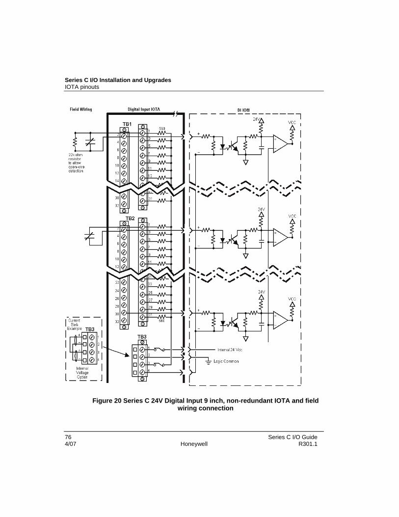
Series C I/O Installation and Upgrades IOTA pinouts
76 Series C I/O Guide 4/07 Honeywell R301.1
Figure 20 Series C 24V Digital Input 9 inch, non-redundant IOTA and field wiring connection

IOTA pinouts Digital Input 24V IOTA
Models CU/CC-TDIL01, CU/CC-TDIL11
Series C I/O Guide 77 R301.1 Honeywell 4/07
Series C 24V Digital Input 12 inch, redundant IOTA is shown.
Figure 21 Series C 24V Digital Input 12 inch, redundant IOTA

Series C I/O Installation and Upgrades IOTA pinouts
78 Series C I/O Guide 4/07 Honeywell R301.1
Using DI channels to report system alarms
Prerequisites
• You have installed and configured Series C 24V digital input I/O modules and associated IOTAs.
• You have alarm cables (51202343) to connect power supply alarm contacts to 24V dc digital inputs on the IOM.
Considerations
You must include digital input channels in the control strategy to generate and report alarms based on their PVs. A typical strategy consists of a Control Module that contains the DI channel blocks where each PV (output) is connected to a PVFL input of a FLAGARRAY block configured for alarming.
The normal condition of the alarm input is ON.
Refer to the Control Building Guide for the following topics
• Creating and saving a control module
• Creating an instance of a basic function block
• Configuring alarms
To connect the alarm cable
Step Action
1 Plug the connection end of the alarm cable into the alarm connection on top of the power supply.
Connect the twisted pair wires to the terminal block 1 on the DI 24V IOTA in the following configuration. The associated alarm pins are also shown.
TERMINAL BLOCK 1
PWR SUPPLY ALARM CONNECTOR
Wire color Channel Screw Description
White 1 1 Power supply 1 alarm + (pin 8)
Black 1 2 Power supply 1 alarm - (pin 3)
Blue 2 3 Power supply 2 alarm + (pin 7)
2
Black 2 4 Power supply 2 alarm - (pin 4)

IOTA pinouts Digital Input 24V IOTA
Models CU/CC-TDIL01, CU/CC-TDIL11
Series C I/O Guide 79 R301.1 Honeywell 4/07
Step Action
Red 3 5 Battery alarm + (pin 2)
Black 3 6 Battery alarm - (pin 1)
Green 4 7 RAM charger alarm + (pin 6)
Black 4 8 RAM charger alarm - (pin 5)
3 Ensure terminal block 3 connections are made in the following configuration
Screw 1 + (internal 24V) to Screw 3 + (external 24V)
Screw 2 - (internal return) to Screw 4 - (external return)

Series C I/O Installation and Upgrades IOTA pinouts
80 Series C I/O Guide 4/07 Honeywell R301.1
Figure 22 Alarm cable connection to the power supply and 24V DI IOTA

IOTA pinouts Digital Output 24V IOTA
Models CU/CC-TDOB01, CU/CC-TDOB11
Series C I/O Guide 81 R301.1 Honeywell 4/07
Digital Output 24V IOTA Models CU/CC-TDOB01, CU/CC-TDOB11
CAUTION
When wiring the Digital Output 24V ensure that the external power is not reversed or the IOM will be damaged.
The Series C Digital Output 24V IOTA board is represented by the following information and graphics.
To access the parts information for the:
• module
• IOTA
• terminal plug-in assembly, and
• fuses
associated with this board and module, refer to Digital Output 24V in the Recommended Spare Parts section.
Field wiring and module protection
The Digital Output 24Volt Module provides a unique and highly functional output power protection method. When a short occurs in the field the following occurs:
• the output circuits sense the over-current condition and shut down the output
• the shut down of the point places the mode of the point into Manual
• an Over-current Soft Failure is generated This failure is maintained until the short circuit condition is repaired and the point is again supplying the proper current.
Only one channel is affected at a time. If multiple channels are affected, they are individually shut down. Any channels that do not have a short circuit condition are unaffected.
• Thermal protection alarm if short in field of > 0.5A.

Series C I/O Installation and Upgrades IOTA pinouts
82 Series C I/O Guide 4/07 Honeywell R301.1
IOTA board and connections
Series C 24V Digital Output 9 inch, non-redundant IOTA is shown.
Figure 23 Series C 24V Digital Output 9 inch, non-redundant IOTA
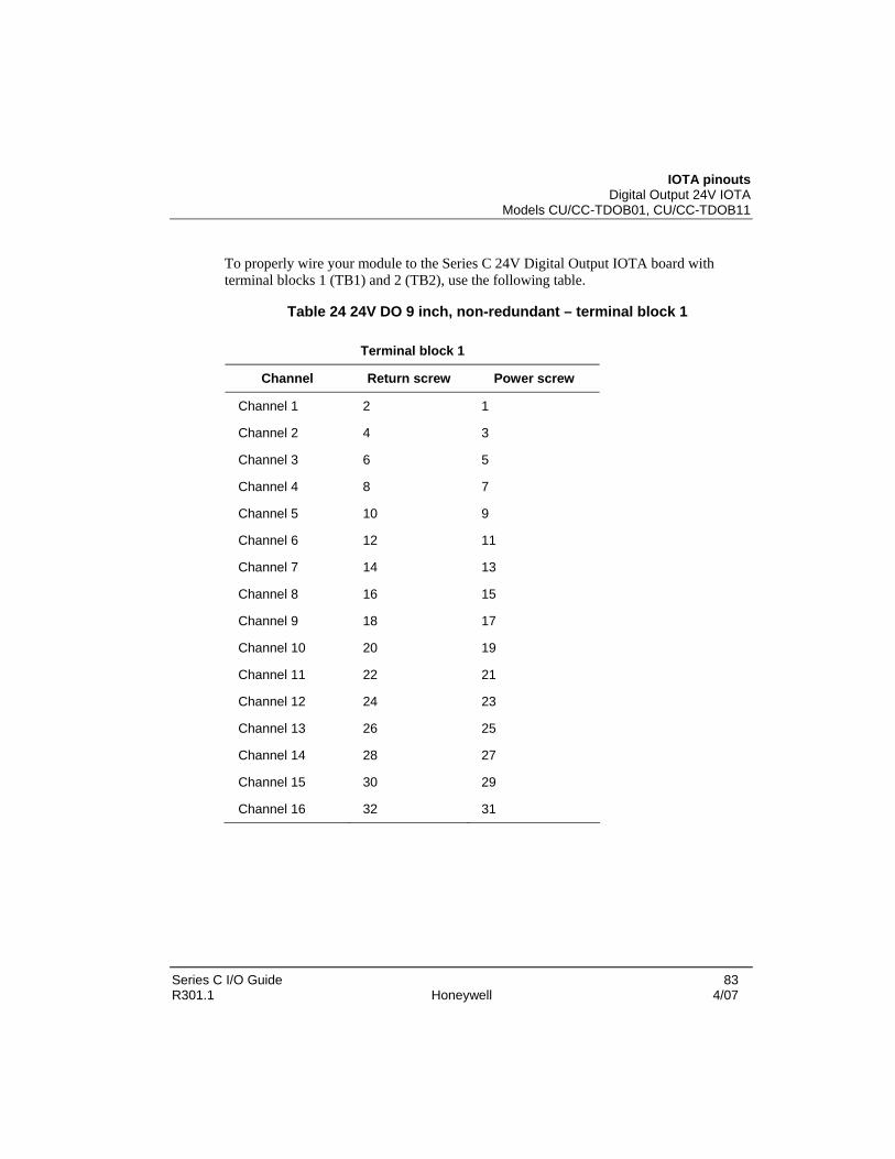
IOTA pinouts Digital Output 24V IOTA
Models CU/CC-TDOB01, CU/CC-TDOB11
Series C I/O Guide 83 R301.1 Honeywell 4/07
To properly wire your module to the Series C 24V Digital Output IOTA board with terminal blocks 1 (TB1) and 2 (TB2), use the following table.
Table 24 24V DO 9 inch, non-redundant – terminal block 1
Terminal block 1
Channel Return screw Power screw
Channel 1 2 1
Channel 2 4 3
Channel 3 6 5
Channel 4 8 7
Channel 5 10 9
Channel 6 12 11
Channel 7 14 13
Channel 8 16 15
Channel 9 18 17
Channel 10 20 19
Channel 11 22 21
Channel 12 24 23
Channel 13 26 25
Channel 14 28 27
Channel 15 30 29
Channel 16 32 31

Series C I/O Installation and Upgrades IOTA pinouts
84 Series C I/O Guide 4/07 Honeywell R301.1
Table 25 24V DO 9 inch, non-redundant – terminal block 2
Terminal block 2
Channel Return screw Power screw
Channel 17 2 1
Channel 18 4 3
Channel 19 6 5
Channel 20 8 7
Channel 21 10 9
Channel 22 12 11
Channel 23 14 13
Channel 24 16 15
Channel 25 18 17
Channel 26 20 19
Channel 27 22 21
Channel 28 24 23
Channel 29 26 25
Channel 30 28 27
Channel 31 29 28
Channel 32 32 31

IOTA pinouts Digital Output 24V IOTA
Models CU/CC-TDOB01, CU/CC-TDOB11
Series C I/O Guide 85 R301.1 Honeywell 4/07
Table 26 24V DO 9 inch, non-redundant – terminal block 3
Terminal block 3
Internal Used with Honeywell’s provided 24v power supply
Screw 1 – internal 24V
Screw 2 – internal return
Screw 3 – external 24V
Screw 4 – external return
External Used with customer’s provided 24v power supply
Screw 1 – internal 24V
Screw 2 – internal return
Screw 3 – external 24V
Screw 4 – external return
CAUTION
When wiring the Digital Output 24V ensure that the external power is not reversed or the IOM will be damaged.

Series C I/O Installation and Upgrades IOTA pinouts
86 Series C I/O Guide 4/07 Honeywell R301.1
Series C 24V Digital Output 9 inch, non-redundant IOTA and field wiring connection is shown
Figure 24 Series C 24V Digital Output 9 inch, non-redundant IOTA and field wiring connections
Series C 24V Digital Output 12 inch, redundant IOTA is shown

IOTA pinouts Digital Output 24V IOTA
Models CU/CC-TDOB01, CU/CC-TDOB11
Series C I/O Guide 87 R301.1 Honeywell 4/07
Figure 25 Series C 24V Digital Output 12 inch, redundant IOTA

Series C I/O Installation and Upgrades IOTA pinouts
88 Series C I/O Guide 4/07 Honeywell R301.1
Digital Output Relay Module IOTA Models CU/CC-TDOR01, CU/CC-TDOR11
The Series C Digital Output IOTA board is represented by the following information and graphics.
To access the parts information for the:
• module
• IOTA
• terminal plug-in assembly, jumper link, slim power relay and
• fuses
associated with this board and module, refer to Digital Output Relay in the Recommended Spare Parts section.
Series C Digital Output Relay non-redundant IOTA is shown.
Figure 26 Series C Digital Output Relay, non-redundant IOTA

IOTA pinouts Digital Output Relay Module IOTA
Models CU/CC-TDOR01, CU/CC-TDOR11
Series C I/O Guide 89 R301.1 Honeywell 4/07
Series C Digital Output Relay redundant IOTA is shown.
Figure 27 Series C Digital Output Relay, redundant IOTA

Series C I/O Installation and Upgrades IOTA pinouts
90 Series C I/O Guide 4/07 Honeywell R301.1
Digital Output Relay Extender board Models CC-SDOR01
Series C Digital Output Relay Extender board is shown below.

IOTA pinouts Digital Output Relay Extender board
Models CC-SDOR01
Series C I/O Guide 91 R301.1 Honeywell 4/07
Figure 28 Series C Digital Output Relay Extender board
To properly wire your module to the Series C Digital Output Relay IOTA board with terminal blocks 1 (TB1) and 2 (TB2), use the following table.
Table 27 DO Relay Extender board– terminal block 1
Terminal block 1
Channel Return screw Power screw
Channel 1 2 1
Channel 2 4 3
Channel 3 6 5
Channel 4 8 7
Channel 5 10 9
Channel 6 12 11
Channel 7 14 13
Channel 8 16 15
Channel 9 18 17
Channel 10 20 19
Channel 11 22 21
Channel 12 24 23
Channel 13 26 25
Channel 14 28 27
Channel 15 30 29
Channel 16 32 31

Series C I/O Installation and Upgrades IOTA pinouts
92 Series C I/O Guide 4/07 Honeywell R301.1
Table 28 DO Relay Extender board– terminal block 2
Terminal block 2
Channel Return screw Power screw
Channel 17 2 1
Channel 18 4 3
Channel 19 6 5
Channel 20 8 7
Channel 21 10 9
Channel 22 12 11
Channel 23 14 13
Channel 24 16 15
Channel 25 18 17
Channel 26 20 19
Channel 27 22 21
Channel 28 24 23
Channel 29 26 25
Channel 30 28 27
Channel 31 29 28
Channel 32 32 31

IOTA pinouts Digital Output Relay Extender board
Models CC-SDOR01
Series C I/O Guide 93 R301.1 Honeywell 4/07
Series C Digital Output Relay Extender board and field wiring connection is shown.
Figure 29 Series C Digital Output Relay Extender board and field wiring connections

Series C I/O Installation and Upgrades IOTA pinouts
94 Series C I/O Guide 4/07 Honeywell R301.1
DO Relay Cover
The DO Relay Extender board being certified as high voltage (with socketed relays and jumpers) is protected by the DO Relay Cover. This complies with the hazardous location agency approvals. The cover has four captured screws; therefore, there are no loose parts.
Mounting the DO Relay Cover
Step Action
1 Align the four captured screws on the cover to the corresponding holes on the DO Relay Extender board.
2 Tighten the four screws securing the cover.
3 This completes this task.
ATTENTION
Before changing any jumper settings, ensure the wires on the terminal block (s) have been removed.

Upgrading firmware in Series C I/O components Digital Output Relay Extender board
Models CC-SDOR01
Series C I/O Guide 95 R301.1 Honeywell 4/07
Figure 30 Series C Digital Output Relay Cover
Upgrading firmware in Series C I/O components
REFERENCE - INTERNAL
Please refer to the Upgrading Firmware in Multiple Series C Devices section in the Control Hardware and I/O Module Firmware Upgrade Guide for information about upgrading firmware in Series C I/O.


Series C I/O Guide 97 R301.1 Honeywell 4/07
Series C I/O Configuration Form Reference
Overview When an IOM block is placed on the Project tab in Control Builder, its associated channel blocks are assigned to the IOM. The following applies to that IOM block:
• You assign each IOM to the IOLINK block (that represents the I/O Link network on which the IOM resides).
• All of the common configuration parameters specific to IOMs are located on the Main Tab of the IOM’s configuration form.
• “Grayed” parameters are either view-only runtime parameters or non-applicable configuration parameters
• The QVCS tab becomes visible when this option is obtained and enabled.
Determining Series C I/O block redundancy Main tab checkbox invokes redundancy
The IOM blocks represent instances of the I/O Module hardware that reside on the I/O Link network. There is a specific IOM block for each I/O Module type supported in Experion.
The IOM block is used to:
• configure the network address (the IOMNUM) of the IOM device.
− If the IOM is configured to be redundant, you enter only one IOMNUM. In either case, only one block is created which handles communication to and from both physical IOMs.
− The hardware design uses a set of push-in IOMNUM identifiers to reduce the chance of duplicate IOMNUMs on the same link.
− Each IOM block generates system events and alarms for soft failures, IOM synchronization, and IOM switchover.

Series C I/O Configuration Form Reference Switchover and Secondary readiness
98 Series C I/O Guide 4/07 Honeywell R301.1
Figure 31 Defining redundancy from the Main tab
Switchover and Secondary readiness A switchover describes the process where a Secondary Series C module assumes the Primary state, and the Primary Series C module assumes the appropriate Secondary state of readiness, depending upon what triggered the switchover. A switchover can be triggered immediately upon the detection of a fault in the Primary or upon the receipt of an operator command.
The ability of a Secondary Series C module to take over the assigned control functions of the Primary depends upon which one of the following readiness states reflects its current state.
Table 29 Redundancy state and module readiness
If Secondary redundancy state is Then, the Secondary module
NotSynced Not synchronized
Cannot assume the Primary state. This is a state of non-readiness. Switchover has not occurred. Ensure redundancy has been selected on the IOMs Main tab.
FoInProg SwapInProg Synchronizing
Cannot assume the Primary State. In this state, the Secondary module is copying database information from the Primary.

Failure conditions and switchover Main tab checkbox invokes redundancy
Series C I/O Guide 99 R301.1 Honeywell 4/07
If Secondary redundancy state is Then, the Secondary module
Syncd Synchronized
Can assume the Primary state upon switchover. In this state, the database in the Secondary is aligned with the database in the Primary. The Secondary closely tracks database changes to maintain its synchronization with the database of the Primary. Otherwise, the Secondary will revert to a Not Synchronized state.
Failure conditions and switchover
ATTENTION
When any failure that results in a switchover occurs in a Secondary module, the Secondary module loses synchronization.
In addition to the failure conditions, this event is reported as diagnostic notification:
• Loss of view of redundant partner on network.
• Loss of private path connection from Primary to Secondary (lonely event).
The following table identifies failure conditions that result in a switchover and those that do not.
Table 30 Failure conditions that result in switchover
Failure conditions that result in a switchover
Failure conditions that do not result in a switchover
Power to Primary module fails. One or all cables fail.
An IOLINK to the Primary Series C module is lost.
One or all network conditioners fail.
Primary Series C module fails. All supplied power to the link fails.

Series C I/O Configuration Form Reference Configuration tools
100 Series C I/O Guide 4/07 Honeywell R301.1
Configuration tools Using Control Builder to create control strategies
The Experion Control Builder application creates control strategies that use Series C I/O data. In developing a valid control strategy, the following activities are required to be supported by Control Builder:
• create hardware blocks,
• associate blocks,
• assign modules,
• assign devices, and
• load components.
Regardless of what tool is used to configure Series C I/O, the IOM must be present during configuration load. If the IOM is not present load errors will occur and a subsequent reload or checkpoint restore will be required.
Refer to the Control Building Guide to create control strategies.
Configuring the Main tab - IOM block Configuring modules - Main tab
The following configuration information pertains to the Main tab for all Series C module types.
Prerequisites • Control Builder is running
• A Series C I/O control module was created
Considerations
• Redundancy is determined by checking the, This IOM is redundant checkbox.
• The QVCS tab becomes visible when this option is obtained and enabled.
• All illustrations used in the procedure are for example purposes only
The following is an example of a DO-24b Block, Configuration form – Main tab.

Configuring the Main tab - IOM block Configuring modules - Main tab
Series C I/O Guide 101 R301.1 Honeywell 4/07
Figure 32 Main tab
To configure the Main tab
Step Action
1 Enter a Tag Name that is more meaningful to you than its default pre-assigned number (ex. Test Strategy DI Module).
2 Item name is based on relationship established in Enterprise Builder

Series C I/O Configuration Form Reference Configuring the Main tab - IOM block
102 Series C I/O Guide 4/07 Honeywell R301.1
Step Action
3 Enter an optional Module Description to explain the I/O Module’s function
4 Enter appropriate values for IOM Number to match the plug-in IOM jumper number. If necessary, press F1 to access on-line help for assistance during this step.
5 If redundancy is required, check the This IOM is redundant checkbox.
6 Proceed to the following procedures to configure parameters on the remaining tabs for the module, or click OK to accept only the changes made so far and return to the Project tree.
Table 31 Main tab parameters
Plain text Parameter name User configurable
Notes
Tag Name TAGNAME Project Only System assigned or user configured unique name. Consisting of up to 16 characters and at lease one character must be a letter (A-Z).
Item Name ITEMNAME Project Only A non-unique name by which an entity is known within the context of the enterprise model.
Module Type IOMTYPE No This non-configurable parameter is a description of the respective I/O module
Description DESC Yes Used to specify descriptive text for the function block. Appears on both detail and group displays.

Configuring the Main tab - IOM block Configuring modules - Main tab
Series C I/O Guide 103 R301.1 Honeywell 4/07
Plain text Parameter name User configurable
Notes
IOM Number IOMNUM Yes This parameter value must be unique on a specific I/O Link, and its range must be between 1 and 40. If IOMNUM=0 and the IOP block is assigned to an I/O Link block, Control Builder automatically defaults the IOMNUM to the next available value on the I/O Link.
Execution State IOMSTATE No Defines execution state
Associated IOLINK IOLINK No Defines associated IOLINK
Database Valid No Defines if database is valid
IOM Location IOPLOCATION Yes Identifies the user-entered location (within the plant) where this IOM can be found.
Number of Channels NUMCHANS No the number of channels available in the IOM
I/O Link Scan Rate SCANRATE Yes Defines scan rate
I/O Link Cable Color IOLINKCOLOR No Defines cable color. See Cabling for color listing.
This IOM is redundant
IOREDOPT Yes Module is part of redundant pair.
Status IOMSTSA No Defines status of IOM: Idle, OK, No Response
Operation IOMOPER No Defines operation status of IOM: Primary, Secondary
Redundancy Status REDDATA No Defines if redundancy is enabled

Series C I/O Configuration Form Reference Configuring the Status Data tab - IOM block
104 Series C I/O Guide 4/07 Honeywell R301.1
Plain text Parameter name User configurable
Notes
Frequency 60/50Hz (AI LLMUX only)
FREQ6050 Yes User-configured power supply determination: 50Hz or 60Hz
Command IOMCOMMAND Yes
Configuring the Status Data tab - IOM block Configuring modules - Status Data tab
The following configuration information pertains to the Status Data tab for the following:
• AI-HART
• AI-LLMUX
• AO-HART
• DI-HV
• DI-24
• DO-24B
Prerequisites
• Control Builder is running
• A Series C I/O control module was created
Considerations • All illustrations used in the procedure are for example purposes only
The following is an example of a DO-24B Block, Configuration form – Status Data tab.

Configuring the Status Data tab - IOM block Configuring modules - Status Data tab
Series C I/O Guide 105 R301.1 Honeywell 4/07
Figure 33 Status Data tab

Series C I/O Configuration Form Reference Configuring the Status Data tab - IOM block
106 Series C I/O Guide 4/07 Honeywell R301.1
To configure the Status Data tab
Step Action
1 Enter the desired values for configuration parameters.
ATTENTION
Configuration parameters vary depending upon the type of module being configured. If necessary, press F1 to access on-line help for assistance during this step.
2 Proceed to the following procedures to configure parameters on the remaining tabs for the module, or click OK to accept only the changes made so far and return to the Project tree.

Configuring the Maintenance tab - IOM block Configuring modules - Maintenance tab
Series C I/O Guide 107 R301.1 Honeywell 4/07
Configuring the Maintenance tab - IOM block Configuring modules - Maintenance tab
The following configuration information pertains to the Maintenance tab for the following module types:
• AI-HART
• AI-LLMUX
• AO-HART
• DI-HV
• DI-24
• DO-24B
Prerequisites
• Control Builder is running
• A Series C I/O control module was created
Considerations Maintenance can only be done from Monitoring.
• All illustrations used in the procedure are for example purposes only
The following is an example of a DO-24B Block, Configuration form – Maintenance tab.

Series C I/O Configuration Form Reference Configuring the Maintenance tab - IOM block
108 Series C I/O Guide 4/07 Honeywell R301.1
Figure 34 Maintenance tab
To Reset Statistics on the Maintenance tab
Step Action
1 From the Statistics Partner frame, monitor the CPU Free Average and CPU Free Minimum settings. To reset statistics to their default values, proceed to

Configuring the Maintenance tab - IOM block Configuring modules - Maintenance tab
Series C I/O Guide 109 R301.1 Honeywell 4/07
Step Action the next step.
2 Click Reset Statistics to reset CPU Free Average and CPU Free Minimum to their default settings.

Series C I/O Configuration Form Reference Configuring Box Soft Failures tab - IOM block
110 Series C I/O Guide 4/07 Honeywell R301.1
Configuring Box Soft Failures tab - IOM block Configuring modules - Box Soft Failures tab
The following configuration information pertains to the Box Soft Failures tab for the following modules:
• AI-HART
• AI-LLMUX
• AO-HART
• DI-HV
• DI-24
• DO-24B
Prerequisites
• Control Builder is running
• A Series C I/O control module was created
Considerations Note: No user-defined configuration setting on the Box Soft Failures tab.
• All illustrations used in the procedure are for example purposes only
The following is an example of a DO-24B Block, Configuration form – Box Soft Failures tab.

Configuring Box Soft Failures tab - IOM block Configuring modules - Box Soft Failures tab
Series C I/O Guide 111 R301.1 Honeywell 4/07
Figure 35 Box Soft Failures tab

Series C I/O Configuration Form Reference Configuring Channel Soft Failures tab - IOM block
112 Series C I/O Guide 4/07 Honeywell R301.1
Configuring Channel Soft Failures tab - IOM block Configuring modules - Channel Soft Failures tab
The following configuration information pertains to the Channel Soft Failures tab for the following modules:
• AI-HART
• AI-LLMUX
• AO-HART
• DI-HV
• DI-24
• DO-24B
Prerequisites
• Control Builder is running
• A Series C I/O control module was created
Considerations Note: No user-defined configuration setting on the Channel Soft Failures tab.
• All illustrations used in the procedure are for example purposes only
The following is an example of a DO-24B Block, Configuration form – Channel Soft Failures tab.

Configuring Channel Soft Failures tab - IOM block Configuring modules - Channel Soft Failures tab
Series C I/O Guide 113 R301.1 Honeywell 4/07
Figure 36 Channel Soft Failures tab

Series C I/O Configuration Form Reference Configuring Server History tab - IOM block
114 Series C I/O Guide 4/07 Honeywell R301.1
Configuring Server History tab - IOM block Configuring modules - Server History tab
The following configuration information pertains to the Server History tab for the following modules:
• AI-HART
• AI-LLMUX
• AO-HART
• DI-HV
• DI-24
• DO-24B
Prerequisites
• Control Builder is running
• A Series C I/O control module was created
Considerations • All illustrations used in the procedure are for example purposes only
The following is an example of a DO-24B Block, Configuration form – Server History tab.

Configuring Server History tab - IOM block Configuring modules - Server History tab
Series C I/O Guide 115 R301.1 Honeywell 4/07
Figure 37 Server History tab

Series C I/O Configuration Form Reference Configuring Server History tab - IOM block
116 Series C I/O Guide 4/07 Honeywell R301.1
To configure the Server History tab.
Step Action
1 Under the Server History tab, enter the appropriate information for Control Level along with values for appropriate parameters related to history collection and archiving. If necessary, press F1 to access on-line help for assistance during this step.
2 Proceed to the following procedures to configure parameters on the remaining tabs for I/O Module, or click OK to accept only the changes made so far and return to the Project tree.
Table 32 Server History tab parameters
Plain text Parameter name User
configurable Notes
Control Level SCANCTRLLVL Yes Indicates Server control level to be associated with this function.
Number of History Parameters
HIST.NUMPARAMS
Yes Defines number of history parameters to be included in History Configuration table.
Parameter Yes Valid parameter name for a parameter associated with the given point that is to be collected and stored as historical data at predetermined intervals.
Description No Provides a brief description of the entered parameter.
FAST Yes Select the Fast type of history collection.
STD Yes Select the Standard type of history collection
EXTD Yes Select the Extended type of history collection
Gating Parameter Yes Optional gating parameter to define conditions under which data for this parameter should be collected.

Configuring Server History tab - IOM block Configuring modules - Server History tab
Series C I/O Guide 117 R301.1 Honeywell 4/07
Plain text Parameter name User configurable
Notes
Gate State Yes Defines gate state for configured gating parameter.
Create New or Edit Existing Server Scripts (Button)
N/A Launch the Server scripting configuration utility.

Series C I/O Configuration Form Reference Configuring Server Displays tab - IOM block
118 Series C I/O Guide 4/07 Honeywell R301.1
Configuring Server Displays tab - IOM block Configuring modules - Server Displays tab
The following configuration information pertains to the Server Displays Failure tab for the following modules:
• AI-HART
• AI-LLMUX
• AO-HART
• DI-HV
• DI-24
• DO-24B
Prerequisites
• Control Builder is running
• A Series C I/O control module was created
Considerations • All illustrations used in the procedure are for example purposes only
The following is an example of a DO-24B Block, Configuration form – Server Displays tab.

Configuring Server Displays tab - IOM block Configuring modules - Server Displays tab
Series C I/O Guide 119 R301.1 Honeywell 4/07
Figure 38 Server Display tab

Series C I/O Configuration Form Reference Configuring Server Displays tab - IOM block
120 Series C I/O Guide 4/07 Honeywell R301.1
To configure the Server Displays tab.
Step Action
1 Under the Server Displays tab, enter the appropriate information to specify related Point Detail Display, Group Detail Display, and Associated Display along with values for appropriate parameters to define Trends and Groups for display. If necessary, press F1 to access on-line help for assistance during this step
2 Click OK on the configuration form to accept all configuration selections made on each configuration tab and to return to the Project tree.
Table 33 Server Display tab parameters
Plain text Parameter name User
configurable Notes
Point Detail Display
SCANPNTDTL Yes By default, a Display template is already entered into Point Detail Display box (for example, sysDtlFTEB.dsp). This template can be used for creating your own display or it can be used as is, provided that your function block name matches name built into detail display that is supplied as a template.
Group Detail Display
SCANGRPDTL Yes By default, a Display template is already entered into the Group Detail Display box (for example, sysGrpFTEB.dsp). This template can be used for creating your own display or it can be used as is, provided that your function block name matches name built into detail display that is supplied as a template
Associated Display
SCANASSOCDSP Yes Name of the Server display to be associated with this function block.
Number of Trends
TREND.NUMPARAMS
Yes Defines the number of trend parameters to be included in the Trends Configuration table.

Configuring Server Displays tab - IOM block Configuring modules - Server Displays tab
Series C I/O Guide 121 R301.1 Honeywell 4/07
Plain text Parameter name User configurable
Notes
Trend # - Yes Defines Trend number to be associated with this trend parameter
Trend Position Yes Defines position of the pen that will be used to trace assigned parameter on Station Trend display.
Trend Parameter - Yes Valid parameter name for a parameter associated with given point that is configured for history collection.
Description - No Provides a brief description of the entered parameter.
Number of Groups
GROUP.NUMPARAMS
Yes Defines the number of group parameters to be included in Groups Configuration table.
Group # - Yes Defines Group number to be associated with this group parameter.
Pos # - Yes Defines number of position configured parameter will occupy in the Station Group display.
Group Parameter - Yes Valid parameter name for a parameter associated with the given point that is configured in the system.
Description - No Provides a brief description of the entered parameter.

Series C I/O Configuration Form Reference Configuring Control Confirmation tab - IOM block
122 Series C I/O Guide 4/07 Honeywell R301.1
Configuring Control Confirmation tab - IOM block Configuring modules - Control Confirmation tab
The Control Confirmation tab is common to all configuration forms for tagged blocks in Control Builder. If you have an optional Electronic Signature license, you can configure electronic signature information for the tagged block through this tab on the block’s configuration form in Control Builder.
The Electronic Signature function aligns with the identical Electronic Signatures function that is initiated through Quick Builder and Station for Server points.
When this block is loaded to a controller,
• its control confirmation configuration (electronic signatures) is also loaded to the Server
• you can view the control confirmation configuration for this tagged object in Station and also make changes to it.
− If you make changes through Station, you must initiate an Upload or Upload with Contents function through the Controller menu in Control Builder for the object in the Monitoring tab to synchronize changes in the Engineering Repository Database (ERDB).
The following configuration information pertains to the Control Confirmation tab for all Series CI/O modules.
Prerequisites
• Control Builder is running
• A Series C I/O control module was created
Considerations Control Confirmation is enabled by checking the Control Confirmation checkbox.
• All illustrations used in the procedure are for example purposes only
The following is an example of a DO-24B Block, Configuration form – Control Confirmation tab.

Configuring Control Confirmation tab - IOM block Configuring modules - Control Confirmation tab
Series C I/O Guide 123 R301.1 Honeywell 4/07
Figure 39 Control Confirmation tab

Series C I/O Configuration Form Reference Configuring Identification tab - IOM block
124 Series C I/O Guide 4/07 Honeywell R301.1
To configure the Control Confirmation tab.
Step Action
1 Under the Control Confirmation tab, check or uncheck the Control Confirmation check box. If necessary, press F1 to access on-line help for assistance during this step.
2 If the Control Confirmation checkbox is checked, the Electronic Signature Type pulldown becomes enabled, with the options to select:
• NONE
• SINGLE
• DOUBLE
2 Proceed to the following procedures to configure parameters on the remaining tabs for I/O Module, or click OK to accept only the changes made so far and return to the Project tree.
Configuring Identification tab - IOM block Configuring modules - Identification tab
The following configuration information pertains to the Identification tab for all Series C I/O modules.
Prerequisites
• Control Builder is running
• A Series C I/O control module was created
Considerations
• All illustrations used in the procedure are for example purposes only
The following is an example of a DO-24B Block, Configuration form – Identification tab.

Configuring Identification tab - IOM block Configuring modules - Identification tab
Series C I/O Guide 125 R301.1 Honeywell 4/07
Figure 40 Identification tab
Table 34 Identification tab parameters
Plain text Parameter name User configurable
Notes

Series C I/O Configuration Form Reference Configuring Identification tab - IOM block
126 Series C I/O Guide 4/07 Honeywell R301.1
Plain text Parameter name User configurable
Notes
Name NAME Yes Unique block name consisting of up to 16 characters to identify the block. At least one character in the name must be a letter (A-Z).
Description DESC Yes Descriptive text appears on detail and group displays to uniquely describe this particular function block
Block Comment 1 Block Comment 2 Block Comment 3 Block Comment 4
BLCKCOMMENT1 BLCKCOMMENT2 BLCKCOMMENT3 BLCKCOMMENT4
Yes Comment to be associated with this block consisting of up to 40 characters.
Library - No Identifies Control Builder Library that is source of template.
System Template - No Identifies System Template that is source for this block.
Base Template - No Identifies Base Template that is used for this block.
Created By CREATEDBY No Identifies user who created block, if operator security is implemented. Otherwise, may just show Default login.
Date Created DATECREATED No Shows date and time template was created. If this block is in Version Control System, shows date and time initial version of template was created.
Last Modified By MODIFIEDBY No Identifies user who made last modifications to block, if operator security is implemented. Otherwise, may just show default login. If this block is in Version Control System, modifications apply to last version of block.

Configuring Identification tab - IOM block Configuring modules - Identification tab
Series C I/O Guide 127 R301.1 Honeywell 4/07
Plain text Parameter name User configurable
Notes
Date Last Modified
VERSIONDATE No Shows date and time last modification was made to block's configuration. If this block is in Version Control System, modification date and time applies to last version of block.

Series C I/O Configuration Form Reference Configuring Identification tab - IOM block
128 Series C I/O Guide 4/07 Honeywell R301.1
Configuring QVCS tab – IOM block Configuring modules - QVCS tab
Qualification and Version Control System (QVCS) provides version management for all tagged objects and a customer defined lifecycle management.
The following configuration information pertains to the QVCS tab for the following modules:
• AI-HART
• AI-LLMUX
• AO-HART
• DI-HV
• DI-24
• DO-24B
Prerequisites • The optional QVCS license has been obtained and enabled
• Control Builder is running
• A Series C I/O control module was created
Considerations
Note: No user-defined configuration setting on the QVCS tab.
• All illustrations used in the procedure are for example purposes only

Configuring Identification tab - IOM block Configuring modules - QVCS tab
Series C I/O Guide 129 R301.1 Honeywell 4/07
The following is an example of a DI-24 Block, Configuration form – QVCS tab.
Figure 41 QVCS tab

Series C I/O Configuration Form Reference Configuring the Calibration tab - IOM block
130 Series C I/O Guide 4/07 Honeywell R301.1
Configuring the Calibration tab - IOM block Configuring modules - Calibration tab
The following configuration information pertains to the Calibration tab for the following modules:
• AI-HART
• AI-LLMUX
• AO-HART
Prerequisites
• Control Builder is running
• A Series C I/O control module was created
Considerations Calibration can only be done from Monitoring.
The Execution State must be set to IDLE before enabling calibration
• All illustrations used in this procedure are for illustration purposes only
The following is an example of an AI-HART Block, Configuration form – Calibration tab.

Configuring the Calibration tab - IOM block Configuring modules - Calibration tab
Series C I/O Guide 131 R301.1 Honeywell 4/07
Figure 42 Calibration tab
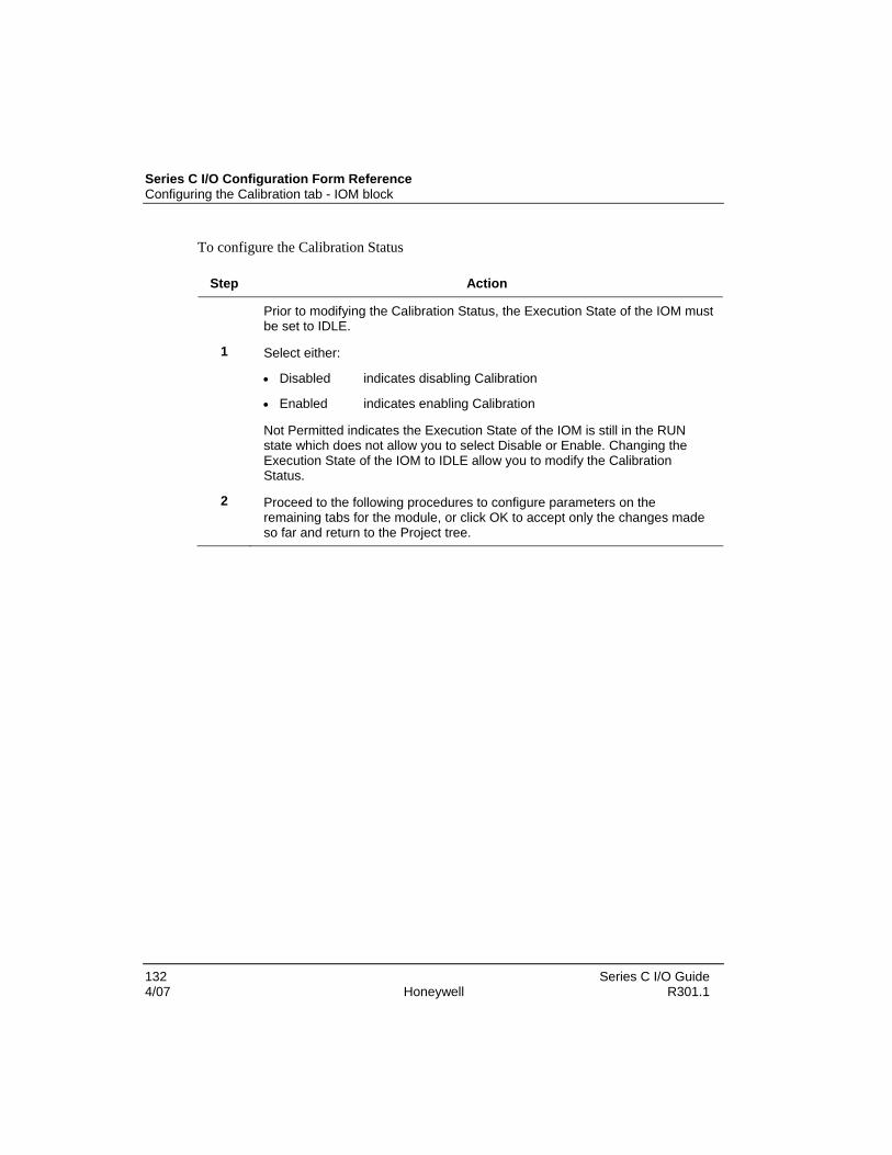
Series C I/O Configuration Form Reference Configuring the Calibration tab - IOM block
132 Series C I/O Guide 4/07 Honeywell R301.1
To configure the Calibration Status
Step Action
Prior to modifying the Calibration Status, the Execution State of the IOM must be set to IDLE.
1 Select either:
• Disabled indicates disabling Calibration
• Enabled indicates enabling Calibration
Not Permitted indicates the Execution State of the IOM is still in the RUN state which does not allow you to select Disable or Enable. Changing the Execution State of the IOM to IDLE allow you to modify the Calibration Status.
2 Proceed to the following procedures to configure parameters on the remaining tabs for the module, or click OK to accept only the changes made so far and return to the Project tree.

Configuring HART Status tab - IOM block Configuring modules HART - Status tab
Series C I/O Guide 133 R301.1 Honeywell 4/07
Configuring HART Status tab - IOM block Configuring modules HART - Status tab
The following configuration information pertains to the HART Status tab for the following:
• AI-HART
• AO-HART
Prerequisites
• Control Builder is running
• A Series C I/O control module was created
Considerations
Note: No user-defined configuration setting on the HART Status tab and there are no configuration items in HART status tab.
• All illustrations used in the procedure are for example purposes only
The following is an example of an AI-HART Block, Configuration form – HART Status tab.

Series C I/O Configuration Form Reference Configuring HART Status tab - IOM block
134 Series C I/O Guide 4/07 Honeywell R301.1
Figure 43 HART Status tab

Configuring the Configuration tab - Channel block Configuring modules - Identification tab
Series C I/O Guide 135 R301.1 Honeywell 4/07
Configuring the Configuration tab - Channel block Configuring modules - Identification tab
The following configuration information pertains to the Configuration tab for Series C I/O Analog Input or Analog Output modules.
Prerequisites
• Control Builder is running
• A Series C I/O control module was created
Considerations
• All illustrations used in the procedure are for example purposes only
The following is an example of an AO Channel Block, Configuration form – Configuration tab.

Series C I/O Configuration Form Reference Configuring the Configuration tab - Channel block
136 Series C I/O Guide 4/07 Honeywell R301.1
Figure 44 Configuration tab

Configuring HART Configuration tab - Channel block Configuring modules – HART Configuration tab
Series C I/O Guide 137 R301.1 Honeywell 4/07
Configuring HART Configuration tab - Channel block Configuring modules – HART Configuration tab
The following configuration information pertains to the Identification tab for all Series C I/O Analog Input and Analog Output modules.
Prerequisites
• Control Builder is running
• A Series C I/O control module was created
Considerations
• All illustrations used in the procedure are for example purposes only
The following is an example of an AI Channel Block, Configuration form – HART Configuration tab.

Series C I/O Configuration Form Reference Configuring HART Configuration tab - Channel block
138 Series C I/O Guide 4/07 Honeywell R301.1
Figure 45 HART Configuration tab

Configuring HART Configuration tab - Channel block Configuring modules – HART Configuration tab
Series C I/O Guide 139 R301.1 Honeywell 4/07
Table 35 HART Configuration tab parameters
Plain text Parameter name User configurable
General configuration
Enable HART HENABLE Yes
Enable HART Alarms and Events Yes
Configured HART Device HCFGDEV Yes
Comm. Error Threshold HCOMTHRS Yes
Command 13, tag descriptor and date
Tag HTAG No
Descriptor HDESC No
Day HDAY No
Month HMONTH No
Year HYEAR No
Command 14, tag descriptor and date
Engineering Units HTDEU No
Upper Transducer Limit HTDURL No
Lower Transducer Limit HTDLRL No
Minimum Span HTDMINSPAN No
Transducer Serial Number HTDSN No

Series C I/O Configuration Form Reference Configuring HART Device Status tab - Channel block
140 Series C I/O Guide 4/07 Honeywell R301.1
Configuring HART Device Status tab - Channel block Configuring modules - Identification tab
The following configuration information pertains to the Identification tab for all Series C I/O modules.
Prerequisites
• Control Builder is running
• A Series C I/O control module was created
Considerations
• All illustrations used in the procedure are for example purposes only
The following is an example of an AI Channel Block, Configuration form – HART Device Status tab.

Configuring HART Device Status tab - Channel block Configuring modules - Identification tab
Series C I/O Guide 141 R301.1 Honeywell 4/07
Figure 46 HART Device Status tab

Series C I/O Configuration Form Reference Configuring HART Device Status tab - Channel block
142 Series C I/O Guide 4/07 Honeywell R301.1
Table 36 HART Device Status tab parameters
Plain text Parameter name User configurable
Communication Status
HART Communication Status HCOMSTS No
Last Communication Failure HCOMFAIL No
Failed Command HCMDFAIL No
Failed Response Code HCMDRESP No
Communication Errors HNCOMERR No

Configuring HART Identification tab - Channel block Configuring modules - Identification tab
Series C I/O Guide 143 R301.1 Honeywell 4/07
Configuring HART Identification tab - Channel block Configuring modules - Identification tab
The following configuration information pertains to the Identification tab for all Series C I/O Analog Input and Analog Output modules.
Prerequisites
• Control Builder is running
• A Series C I/O control module was created
Considerations
• All illustrations used in the procedure are for example purposes only
The following is an example of an AI Channel Block, Configuration form – HART Identification tab.

Series C I/O Configuration Form Reference Configuring HART Identification tab - Channel block
144 Series C I/O Guide 4/07 Honeywell R301.1
Figure 47 HART Identification tab

Configuring HART Identification tab - Channel block Configuring modules - Identification tab
Series C I/O Guide 145 R301.1 Honeywell 4/07
Table 37 HART Identification tab
Plain text Parameter name User configurable
Configured device
Manufacturer HDVMFGCD No
Type HDVTYPCD No
Type (Name) HDVTYPCDNAME No
Revision HDVRREVCD No
Id (Serial number) HDEVIDCD No
Installed device
Manufacturer HDEVMFG No
Type HDEVTYP No
Type (Name) HDEVTYPNAME No
Revision HDEVRREV No
Id (Serial number) HDVID No
Device Type Mismatch HDEVMISM No
Device Revision Mismatch HREVMISM No
Device ID Mismatch HDEVIDFL No
Accept Device ID ACCEPTDEV No
Supported HART Version HARTVERSION No
Universal Command Revision HUCMREV No
Software Revision HSWREV No
Hardware Revision HHWREV No

Series C I/O Configuration Form Reference Configuring HART Variables tab - Channel block
146 Series C I/O Guide 4/07 Honeywell R301.1
Configuring HART Variables tab - Channel block Configuring modules - Identification tab
The following configuration information pertains to the Identification tab for all Series C I/O Analog Input or Analog Output modules.
Prerequisites
• Control Builder is running
• A Series C I/O control module was created
Considerations
• All illustrations used in the procedure are for example purposes only
The following is an example of an AI Channel Block, Configuration form – HART Variables tab.

Configuring HART Variables tab - Channel block Configuring modules - Identification tab
Series C I/O Guide 147 R301.1 Honeywell 4/07
Figure 48 HART Variables tab

Series C I/O Configuration Form Reference Configuring HART Variables tab - Channel block
148 Series C I/O Guide 4/07 Honeywell R301.1
Table 38 HART Variables tab parameters
Plain text Parameter name User configurable
Scan HART Variables HSCANCFG No
Dynamic variables
Name HDYNNAME Yes
Variable Code HDYNDVC Yes
Descriptor HDYNDSC Yes
Value HDYNVAL Yes
Units HDYNEU Yes
Device variables
Name HSLOTNAME Yes
Variable Code HSLOTDVC Yes
Descriptor HSLOTDSC Yes
Value HSLOTVAL Yes
Units HSLOTEU Yes

Configuring HART Notifications tab - Channel block Configuring modules - Identification tab
Series C I/O Guide 149 R301.1 Honeywell 4/07
Configuring HART Notifications tab - Channel block Configuring modules - Identification tab
The following configuration information pertains to the Identification tab for all Series C I/O Analog Input and Analog Output modules.
Prerequisites
• Control Builder is running
• A Series C I/O control module was created
Considerations
• All illustrations used in the procedure are for example purposes only
The following is an example of an AO Channel Block, Configuration form – HART Notifications tab.

Series C I/O Configuration Form Reference Configuring HART Notifications tab - Channel block
150 Series C I/O Guide 4/07 Honeywell R301.1
Figure 49 HART Notifications tab
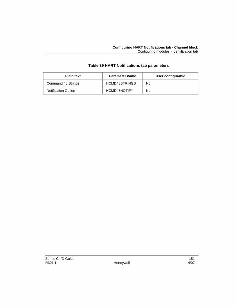
Configuring HART Notifications tab - Channel block Configuring modules - Identification tab
Series C I/O Guide 151 R301.1 Honeywell 4/07
Table 39 HART Notifications tab parameters
Plain text Parameter name User configurable
Command 48 Strings HCMD48STRINGS No
Notification Option HCMD48NOTIFY No

Series C I/O Configuration Form Reference Configuring Dependencies tab - Channel block
152 Series C I/O Guide 4/07 Honeywell R301.1
Configuring Dependencies tab - Channel block Configuring modules - Dependencies tab
The following configuration information pertains to the Identification tab for all Series C I/O Analog Input and Analog Output modules.
Prerequisites
• Control Builder is running
• A Series C I/O control module was created
Considerations
• All illustrations used in the procedure are for example purposes only
The following is an example of an AO Channel block, Configuration form – Dependencies tab.

Configuring Dependencies tab - Channel block Configuring modules - Dependencies tab
Series C I/O Guide 153 R301.1 Honeywell 4/07
Figure 50 Dependencies tab

Series C I/O Configuration Form Reference Configuring Template Defining tab - Channel block
154 Series C I/O Guide 4/07 Honeywell R301.1
Configuring Template Defining tab - Channel block Configuring modules - Identification tab
The following configuration information pertains to the Identification tab for all Series C I/O Analog Input and Analog Output modules.
Prerequisites
• Control Builder is running
• A Series C I/O control module was created
Considerations
• All illustrations used in the procedure are for example purposes only
The following is an example of an AO Channel Block, Configuration form – Template Defining tab.

Configuring Template Defining tab - Channel block Configuring modules - Identification tab
Series C I/O Guide 155 R301.1 Honeywell 4/07
Figure 51 Template Defining tab


Series C I/O Guide 157 R301.1 Honeywell 4/07
Series C I/O Configuration
Adding an IOM to Project The following IOMs are added to the Project tab using the either the File menu method or the Drag and Drop method:
• AI-HART High Analog Input, HART Capable, 16 channels
• AI-LLMUX – Low Level Analog Input Mux, 64 channels
• AO-HART – Analog Output, HART Capable, 16 channels
• DI-24 – Low Voltage (24VDC) Digital Input, 32 channels
• DI-HV – High Voltage Digital Input, 32 channels
• DO-24B – Bussed Low Voltage Digital Output, 32 channels
Using the File menu method To add an IOM to the Project tab by the File menu method:
Step Action
1 Click File -> New -> I/O Modules -> Series C I/O. A list of the available Series C I/O block types is displayed.

Series C I/O Configuration Adding an IOM to Project
158 Series C I/O Guide 4/07 Honeywell R301.1
Step Action
2 Select a block types from the drop down list. A Block Parameters configuration form is displayed
3 Type a new name in the highlighted name field.
4 Click the OK button. A new IOM instance is created in the Project tab.
TIP
IOM names can be up to 16 characters long.

Adding an IOM to Project Using the drag and drop method
Series C I/O Guide 159 R301.1 Honeywell 4/07
Using the drag and drop method To add an IOM to the Project tab by the drag and drop method:
Step Action
1 Drag an IOM icon from the Library tab to an open area on the Project tab. Name New Function Block(s) dialog appears.
2 Accept or type a new tagname in the Destination column.
3 Click the Finish button. The IOM is displayed in the Project tab.
TIP
IOM names can be up to 16 characters long.

Series C I/O Configuration Assigning an IOM to an IOLINK in the Project tab
160 Series C I/O Guide 4/07 Honeywell R301.1
Assigning an IOM to an IOLINK in the Project tab Using the Assignment dialog box
To assign an IOM to an IOLINK function block using the Assignment Dialog Box:
Step Action
1 Click the Assign button in the toolbar. The Execution Environment Assignment dialog appears.
2 Select an IOM module from the Available Modules area.
3 Click the Assign button. The IOM is loaded to the Assign To: area
4 Click the Close button to complete the assignment.
TIP
The IOM is assigned to an IOLINK function block in the manner as CM blocks are assigned to a CEEC300 function block.
You can also drag and drop the IOM from the Project tab to the IOLINK function block.

Adding an IOC block to a Control Module Using the Project tab drag and drop
Series C I/O Guide 161 R301.1 Honeywell 4/07
Adding an IOC block to a Control Module Using the Project tab drag and drop
When an IOM block is created in the Project Tab, all of its associated IOC blocks are also created. Clicking the + (plus sign) for the IOM expands the tree down to the IOC level. You can drag and drop the IOC blocks into Control Modules. The Series C I/O IOC block parameters can then be wired to other blocks in the same manner as existing Experion function blocks.
Prerequisites
• Control Builder is running
• Controller was created, CM was created, IOM was added and assigned to an IOLINK
To add an IOC to a Control; Module by dragging and dropping from the Project tab:
Step Action
1 Click the + (plus sign) to expand the IO in the Project tab.

Series C I/O Configuration Adding an IOC block to a Control Module
162 Series C I/O Guide 4/07 Honeywell R301.1
Step Action
2 Drag an IOC to into the Control Module. The cursor changes to denote an IOC is captured and available for placement in to the CM control window.

Adding an IOC block to a Control Module Using the Library tab - drag and drop
Series C I/O Guide 163 R301.1 Honeywell 4/07
Step Action
3 Collect the appropriate IOC blocks.
Using the Library tab - drag and drop You can integrate IOC blocks into control strategies without assigning them to an IOM. This ability provides hardware independent control building.
Prerequisites
• Control Builder is running
• Controller was created, CM was created, IOM was added and assigned to an IOLINK
Considerations
• IOC blocks cannot be added to Control Modules already assigned to a FIM.
• The Control Module cannot be loaded until all IOC blocks have been assigned to IOM blocks.

Series C I/O Configuration Adding an IOC block to a Control Module
164 Series C I/O Guide 4/07 Honeywell R301.1
To add an IOC to a Control Module by dragging and dropping from the Library tab:
Step Action
1 Drag a Series C I/O channel block icon to an open area in a Control Module. The cursor changes to denote an IOC is captured and available for placement in to the CM control window.

Adding an IOC block to a Control Module Using the Library tab - drag and drop
Series C I/O Guide 165 R301.1 Honeywell 4/07
Step Action
2 The Series C I/O IOC block parameters can then be wired to other blocks in the same manner as existing Experion function blocks.

Series C I/O Configuration Assigning an IOC block to an IOM
166 Series C I/O Guide 4/07 Honeywell R301.1
Assigning an IOC block to an IOM IOC block assignment
The IOC must be assigned to a valid IOM to allow proper configuration.
Prerequisites
• A Control Module cannot be loaded unless all of its IOC blocks have been assigned to IOM blocks.
• IOC blocks cannot be assigned to an available channel on an IOM block if the IOM’s channel currently exists in the Monitoring Tree.
Considerations • All illustrations used in the procedure are for example purposes only.
To assign an IOC to an IOM using the Function Block Assignment Dialog box:
Step Action Result
1 Double-click the given CM icon in the Project tree. Opens CM in control chart area.
2 Right-click an IOC channel block in the control chart area.
Opens shortcut menu.

Assigning an IOC block to an IOM IOC block assignment
Series C I/O Guide 167 R301.1 Honeywell 4/07
Step Action Result
2 Select Function Block Assign Opens Function Block Assignment Dialog that list compatible IOCs associated with the IOM assigned to an IOLINK.
3 Click the check box for desired channel in given IOM.
Selects channel for assignment.
4 Click the Assign button. Selected IOC block is assigned.
5 Click the dialog close button to complete the assignment.
Confirmation dialog appears.
6 Click the Yes button to accept the changes. Function Block Assignment Dialog box closes.

Series C I/O Configuration Unassigning an IOC block from an IOM
168 Series C I/O Guide 4/07 Honeywell R301.1
Unassigning an IOC block from an IOM IOC block unassignment
An IOC function block can be unassigned from an IOM. Unassigned IO channels are available for reassigning only after the CM is saved.
Prerequisites
• IOC blocks cannot be unassigned if the IOC currently exists in the Monitoring Tree.
Considerations
• All illustrations used in the procedure are for example purposes only.
To unassign an IOC from an IOM using the Function Block Assignment Dialog Box:
Step Action Results
1 Double-click given CM in the Project tree. Opens CM in control chart area.
Right-click the IOC channel block.
Opens shortcut menu.
2 Select Function Block Unassign Opens Function Block Assignment Dialog that list compatible IOCs associated with the IOM assigned to an IOLINK
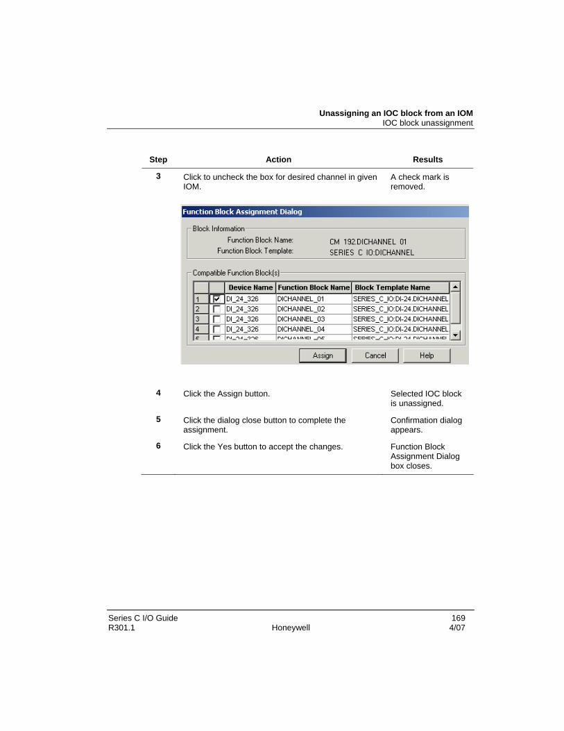
Unassigning an IOC block from an IOM IOC block unassignment
Series C I/O Guide 169 R301.1 Honeywell 4/07
Step Action Results
3 Click to uncheck the box for desired channel in given IOM.
A check mark is removed.
4 Click the Assign button. Selected IOC block is unassigned.
5 Click the dialog close button to complete the assignment.
Confirmation dialog appears.
6 Click the Yes button to accept the changes. Function Block Assignment Dialog box closes.

Series C I/O Configuration Defining Channel blocks
170 Series C I/O Guide 4/07 Honeywell R301.1
Defining Channel blocks Overview
Each Series C I/O channel (IOC) block represents a single I/O point within an I/O module (which can be either input or output). There are certain attributes and parameters that are common to all I/O channel blocks. The Series C IOC block has a point execution state, similar to the PM IOC block. This allows for easy reconfiguration of a single channel without disrupting the operation of the entire IOM.
TIP
In the TPS environment, a channel block is equivalent to one slot in the IO processor.
Each IOC block must have an “assignment” block and “containment” block in order for it to be loadable. The following table describes these blocks.
Table 40 I/O Channel block type
Block name Description
Assignment IOC is associated with a specific slot number on an IOM block
Containment IOC exists in a Control Module Common features of I/O channel blocks
There are certain attributes and parameters that are common to all I/O channel blocks. The following section identifies these common features.
Defining Mode and Attribute settings
The MODE parameter determines the operating mode for the channel block. These modes apply to both DO and AO channel blocks.
Operators are only permitted to change MODE if:
• MODEPERM is set to Permit, and
• REDTAG is set to Off

Defining Channel blocks Defining Mode and Attribute settings
Series C I/O Guide 171 R301.1 Honeywell 4/07
Note: Mode Permissive = Indicates if the operator can change the mode of a function block Red Tag - Allows the user to set the FB as being "out-of-service"; this indicates that the FB or the associated control strategy needs repair, or is being repaired.
The following modes apply to the MODE parameter.
Table 41 Mode parameter – channel block
Operating mode Description
Manual (Man) Provides direct control over the output value of the channel, regardless of any continuous control strategy.
Cascade (Cas) Data point receives its output value from a primary data point.
The MODEATTR (mode attribute) parameter determines who has authority to change certain parameters on the function block.
The following modes apply to the MODEATTR parameter.
Table 42 Mode Attribute parameter – channel block
Operating mode Description
Operator Operator supplies the output value and mode for the channel (operator access level).
Program Program supplies the output value and mode for the channel (program access level).
Defining load attributes
When defining the load attributes, the channel block copies:
• the Normal Mode parameter (NMODE) into the MODE parameter, and
• the Normal Mode attribute (NMODATTR) into the MODEATTR parameter
CONSIDERATIONS:
Possible entries for the NMODE parameter:
• Man

Series C I/O Configuration Defining Channel blocks
172 Series C I/O Guide 4/07 Honeywell R301.1
• Cas
• None
Possible entries for the NMODATTR parameter
• Operator
• Program
• None
To define the channel block and copy the NMODE (normal mode) and NMODATTR attributes:
Step Action Result
1 Press the NORM button on the integrated keyboard (IKB).
OR
Press the Operator Entry Panel (OEP) at the operator station.
The content of the NMODE is copied into the MODE parameter and becomes the mode for the channel block.
The content of the NMODATTR is also copied into the MODEATTR parameter and becomes the mode for the channel block.
Defining Fault State Handling and Fault Option settings
AO and DO channel blocks are configured so, that “if the communication between the controller and the I/O module is disrupted for 8 seconds”, the upstream control strategy is assumed to have failed. The FAULTOPT parameter allows you to specify the behavior of an individual output when a fault condition exists.
Table 43 Channel block fault conditions and results
Fault conditions exist when Result
Loss of communications due to:
• C300 failure
• IOLEE failure
• Dual IOL cable failure
CEE failure, but IOLEE is up and running
All outputs on the IOM, regardless of their PTEXEST value, transition to their respective FAULTOPT states, within 8 seconds.

Defining Channel blocks Defining Mode and Attribute settings
Series C I/O Guide 173 R301.1 Honeywell 4/07
NOTE: REDTAG configuration overrides FAULTOPT configuration. Channels with REDTAG configured to ON holds the output in FAULTED state, regardless of FAULTOPT configuration.
The following figure illustrates where the output is directed to either the normal location or a Fault location.
Figure 52 AO and DO fault state (FAULTST) transitions
Specific fault state handling depends upon the parameter settings for MODE and MODEATTR. Refer to the tables below for AO and DO settings.
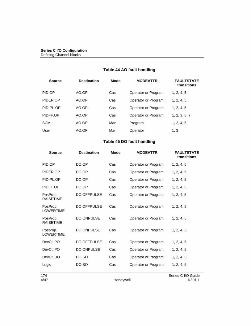
Series C I/O Configuration Defining Channel blocks
174 Series C I/O Guide 4/07 Honeywell R301.1
Table 44 AO fault handling
Source Destination Mode MODEATTR FAULTSTATE transitions
PID.OP AO.OP Cas Operator or Program 1, 2, 4, 5
PIDER.OP AO.OP Cas Operator or Program 1, 2, 4, 5
PID-PL.OP AO.OP Cas Operator or Program 1, 2, 4, 5
PIDFF.OP AO.OP Cas Operator or Program 1, 2, 3, 5, 7
SCM AO.OP Man Program 1, 2, 4, 5
User AO.OP Man Operator 1, 3
Table 45 DO fault handling
Source Destination Mode MODEATTR FAULTSTATE transitions
PID.OP DO.OP Cas Operator or Program 1, 2, 4, 5
PIDER.OP DO.OP Cas Operator or Program 1, 2, 4, 5
PID-PL.OP DO.OP Cas Operator or Program 1, 2, 4, 5
PIDFF.OP DO.OP Cas Operator or Program 1, 2, 4, 5
PosProp. RAISETIME
DO.OFFPULSE Cas Operator or Program 1, 2, 4, 5
PosProp. LOWERTIME
DO.OFFPULSE Cas Operator or Program 1, 2, 4, 5
PosProp. RAISETIME
DO.ONPULSE Cas Operator or Program 1, 2, 4, 5
Posprop. LOWERTIME
DO.ONPULSE Cas Operator or Program 1, 2, 4, 5
DevCtl.PO DO.OFFPULSE Cas Operator or Program 1, 2, 4, 5
DevCtl.PO DO.ONPULSE Cas Operator or Program 1, 2, 4, 5
DevCtl.DO DO.SO Cas Operator or Program 1, 2, 4, 5
Logic DO.SO Cas Operator or Program 1, 2, 4, 5

Defining Channel blocks Defining Mode and Attribute settings
Series C I/O Guide 175 R301.1 Honeywell 4/07
Source Destination Mode MODEATTR FAULTSTATE transitions
SCM DO.OP Man Program 1, 2, 4, 5
SCM DO.OFFPULSE Man Program 1, 2, 4, 5
SCM DO.ONPULSE Man Program 1, 2, 4, 5
SCM DO.SO Man Program 1, 2, 4, 5
User DO.OP Man Operator 1, 3
User DO.SO Man Operator 1, 3
The FAULTOPT parameter determines the behavior of an individual output value when a fault condition exists. The following modes apply to the FAULTOPT parameter:
Table 46 FAULTOPT parameter settings
Operating mode
Description AO channels DO channels
Hold Holds output at last good value
Applicable to all configurations
Applicable to all configurations
Unpower Output goes to an unpowered value
Applicable to all configurations
Applicable to all configurations
Power Output goes to a powered value
Not applicable to AO channels
Not applicable to DO channels for PWM operation.
Use Fault Value
Output goes to the value specified by the FAULTVALUE parameter
Not applicable to DO channels configured for STATUS, ONPULSE or OFFPULSE operation.
The FAULTOPT configuration also defines the state of the output in case of total IOM hard failure also. This feature is mainly applicable to the DO channels configured for STATUS operation.

Series C I/O Configuration Defining Channel blocks
176 Series C I/O Guide 4/07 Honeywell R301.1
FAULTED state and IOM hard failure
Total IOM hard failure means:
• dual IOM failure in the case of redundant setup
• assumes that there is no disruption 24V power to the I/O modules
The following table summarizes the state of the output for all applicable output configurations in the case of transitioning to FAULTED state or on total IOM failure.
Table 47 IOM hard failure and output state
Unpower Power Hold Fault value
AO
Faulted state
0mA Not applicable Hold last good OP value
Hold configured value
Total IOM Failure
0mA Not applicable 0mA 0mA
DO STATUS
Faulted state
Drive LOW Drive HIGH Hold last good SO value
Not applicable
Total IOM Failure
Drive LOW Drive HIGH Hold last good SO value
Not applicable
DO PWM
Faulted state
Drive LOW Not applicable Continues of PWM as per the last good Op value.
Continues of PWM as per the configured value.
Total IOM Failure
Drive LOW Not applicable Terminates the PWM and drive LOW.
Terminates the PWM and drive LOW.
DO ONPULSE/OFFPULSE
Faulted state
Drive LOW Drive HIGH Proceeds to the normal completion of any on-going pulse and hold quiescent state.
Not applicable

Defining Channel blocks Defining Mode and Attribute settings
Series C I/O Guide 177 R301.1 Honeywell 4/07
Total IOM Failure
Drive LOW Drive HIGH Terminates any on-going pulse immediately and hold quiescent state.
Not applicable
Defining PV Source selection settings
The PVSOURCE parameter allows you to determine the source of the PV for the data channel.
Table 48 PV Source settings
If PVSOURCE is
Auto
• AI channel’s Range Checking and Filtering circuit provides PV, or
• DI channel’s PVAUTO parameter provides PV
Man
• PV can be entered manually, or
Sub
• PV can come from a sequence program
Additionally, the PVSRCOPT parameter determines if it is permissible to change the PV source to a source other than Auto.
The following modes apply to the PVSRCOPT parameter.
Table 49 PVSRCOPT settings
Operating mode Description
OnlyAuto allows the PV to be set only Automatically
All allows the manual setting of PV

Series C I/O Configuration Defining Channel blocks
178 Series C I/O Guide 4/07 Honeywell R301.1
Defining the REDTAG settings
The REDTAG parameter allows you to set channel as being “out of service” indicating that this channel or its associated control loops needs repair, or is being repaired. Once a channel is put in the red tag condition, its output is frozen at the last value.
REDTAG can only be set and cleared when:
• MODE = MAN
• MODATTR = Operator
Table 50 REDTAG settings
When channel is placed in REDTAG condition
Result
Channel output is frozen at last value (including MODE and MODATTR)
The value of OP takes precedence over the FAULTOPT settings.
Channels • cannot be deleted
• can be reloaded - the load produces errors because the parameters could not be set on the load.

Defining Channel blocks Enabling HART
Series C I/O Guide 179 R301.1 Honeywell 4/07
Enabling HART
Overview
Series C I/O IOMs do not have an independent HART device block. Instead the HART data is fully contained within an AI or AO block and:
• enabled when HENABLE parameter is set to TRUE (This is done on the AI channel block HART Configuration tab)
• becomes an Experion “tagged” entity and can generate alarms based on its “tagged” name in Station.
When AI and AO channel blocks are enabled, five additional HART tabs become exposed. These tabs are used exclusively for details about the attached HART device and are identical for AI and AO channels. These tabs are:
HART Configuration HART Identification HART Notifications
HART Device Status HART Variables

Series C I/O Configuration Defining Channel blocks
180 Series C I/O Guide 4/07 Honeywell R301.1
Figure 53 Series C I/O AI or AO - HART tabs
AI and AO channel blocks also have two additional tabs that appear on all tagged Experion blocks. They are the Server History and Server Displays tab. These tabs also become exposed when HART is enabled.

Defining Channel blocks Comparing parameters between Series C and PMIO
Series C I/O Guide 181 R301.1 Honeywell 4/07
Parameters exposed after HART is enabled
For the most part, the Series CI/O HART parameters are identical to their PM I/O HART counterparts. The following table displays parameters that are only exposed when HART is enabled – all located on the Configuration tab.
Table 51 HART parameters
Parameter Works the same as PMIO
ACCEPTRNG URL, URV LRV LRL HPVMISM
Yes Yes Yes Yes Yes Yes
NOTE: Only 1-5V sensor type will be supported when HART is enabled.
Comparing parameters between Series C and PMIO
HPVCHAR, which is used in PM I/O, is not used in Series C I/O. PVCHAR is used instead, and only valid enumerations (depending on the settings for HENABLE and IOM TYPE) are shown to you.
Some HART parameters are only valid for HART Protocol Version 6. Series C IOMs support HART 6.0 features such as Extended Device Status, Configuration Change Counter, Variable Status and Classification Codes. The current release of Series C I/O supports these HART 6 parameters:
HART 6 supported parameters for current Series C I/O
HDYNCC HMAXDEVVARS HNSMMINPRE HSLOTST
HDYNST HNCFGCHG HSLOTCC Using Block Copy
Parameter values not copied during Block Copy
IOP and CHANNUM are the only configuration parameter values not copied during a Block Copy operation.

Series C I/O Configuration Defining AI Channel Blocks
182 Series C I/O Guide 4/07 Honeywell R301.1
Defining AI Channel Blocks Overview
The AI channel block represents a single analog input point on either an AI-HART or AI-LLMUX I/O Module. The type of analog input IOM needed is based on the:
• type of field sensor that is providing the input to the channel
• PV characterization options you select (as listed in the table in Determining PV Characterization):
Channels contained within an AI-HART IOM are generally used for control points. Channels located in the AI-LLMUX IOM are generally used for data acquisition points.
The analog input channel converts an analog PV signal received from a field sensor to engineering units for use by other function blocks in the C300, and by the rest of Experion.
To accomplish this function, the analog input channel, as shown in figure below, performs:
• Analog-to digital conversion
• PV characterization
• Range Checking and PV filtering
• PV source selection
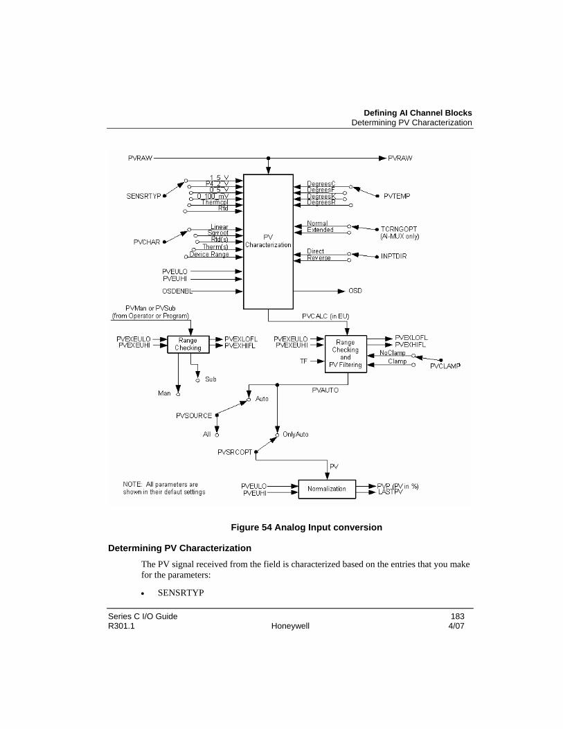
Defining AI Channel Blocks Determining PV Characterization
Series C I/O Guide 183 R301.1 Honeywell 4/07
Figure 54 Analog Input conversion
Determining PV Characterization The PV signal received from the field is characterized based on the entries that you make for the parameters:
• SENSRTYP

Series C I/O Configuration Defining AI Channel Blocks
184 Series C I/O Guide 4/07 Honeywell R301.1
• PVCHAR
• PVTEMP
• INPTDIR, and
• TCRNGOPT
The input PV signal is:
a) Converted to a raw PV signal (PVRAW) whose units can be %, ratio, millivolts, microvolts, or milliohms depending on the entry made for the SENSRTYP parameter
b) then converted to the engineering units
The engineering unit conversions that are performed in the AI-HART and AI-LLMUX points are listed in the table below.
Table 52 AI engineering unit conversions
Sensor type (SENSRTYP)
AI Module type
PVCHAR Options
PVRAW (note 1)
PVCALC(note 2)
Bad PV detection
0-5-V (0 to 5 volts)
AI-HART Linear square rt. percent EU Range check on PVCALC
P4_2_V (0.4 to 2 volts)
AI-HART Linear square rt. percent EU Range check on PVCALC. Checks for open input
1_5_V (1 to 5 volts)
AI-HART Linear square rt. Device Range
percent EU Range check on PVCALC. Checks for open input
0_100_mV (0 to 100 mV)
AI-LLMUX Linear millivolts EU (note 3)
Range check on PVCALC
Thermcpl (Thermocouple)
AI-LLMUX See PVCHAR for complete list
microvolts EU Range check on PVCALC. Open thermocouple detection
RTD AI-LLMUX See PVCHAR for complete list
milliohms EU Range check on PVCALC

Defining AI Channel Blocks Determining Linear Conversion
Series C I/O Guide 185 R301.1 Honeywell 4/07
LEGEND:
EU = Engineering Units AI-HART = HART capable, High Level Analog input AI-LLMUX Low Level Analog Multiplexer PVCALC = Calculated PV PVCHAR = PV Characterization PVRAW = PV received from field and converted to digital form by the A/D converter
Notes:
1. PVRAW is the voltage signal at the IOTA as a percentage of the voltage range for the sensor type. The exceptions are as follows
a. For a thermocouple sensor type, PVRAW is in microvolts, after reference junction compensation. If an open thermocouple is detected, PVRAW is set to NaN.
b. For an RTD sensor type, PVRAW is in milliohms, after lead-wire compensation. If an open RTD is detected, PVRAW is set to NaN.
c. For a 0-100 millivolt sensor type, PVRAW is the IOTA voltage input for the slot.
2. If the diagnostics determine that the A/D converter has failed, PVRAW of the slot is set to NaN.
3. The normal operating range for PVRAW is configured by you (for a thermocouple 0% = PVRAWLO, 100% = PVRAWHI.
Determining Linear Conversion
The PVRAW value is converted to a floating-point number. The output value of the linear conversion is PVCALC, which is calculated based on the raw input span (for 0-100 mV sensor type only), and the engineering unit span.
The state of the input direction parameter (INPTDIR) is taken into consideration during the calculation of PVCALC as follows:

Series C I/O Configuration Defining AI Channel Blocks
186 Series C I/O Guide 4/07 Honeywell R301.1
Determining Square Root Conversion
The square-root calculation is applied to the PVRAW input such that
100% of span = 1.0
The square-rooted value is then converted to engineering units based on the configured PV engineering-unit range values. (For example, square root of 100% = 100%; square root of 50% = 70.71%.)
The output value of the square-root conversion is PVCALC, which is calculated based on the state of the input direction parameter (INPTDIR) as follows

Defining AI Channel Blocks Determining Thermal Conversion
Series C I/O Guide 187 R301.1 Honeywell 4/07
Determining Thermal Conversion
Thermal linearization is performed on thermocouple and RTD input types. All thermocouples (#therm) listed in the PVCHAR parameter definition, are supported by the analog input point. The range of the thermocouple type used with the AI-LLMUX channel can be increased by selecting Extended as the entry for the TCRNGOPT parameter.
The AI-LLMUX channels calculate the reference junction compensation from the measured reference junction output level. This value is stored and then later converted back to microvolts, with respect to 0 degrees C, for each thermocouple that is to be compensated. The cold-junction reference compensation (PVREFJN) parameter is expressed in microvolts for the specified thermocouple and is added to the microvolt value for PVRAW.
All RTDs (*RTD) listed in the PVCHAR parameter definition, are supported by the analog input point:
For an RTD, the AI-LLMUX channels calculate the lead-wire compensation and then subtract the value from PVRAW. The maximum allowable lead-wire resistance and intrinsic safety barrier resistance for the RTDs are listed in the table below.
Table 53 RTD lead wire characteristics

Series C I/O Configuration Defining AI Channel Blocks
188 Series C I/O Guide 4/07 Honeywell R301.1
Maximum allowable lead resistance – Note 1
(units are ohms)
Maximum allowable intrinsic safety barrier resistance
(units are ohms)
RTD type Entire loop Per leg Entire loop Per leg
Pt:100 DIN characterization 20 10 18 18
Pt:100 JIS characterization 20 10 18 18
Ni: 120 Edison type 7 characterization
20 10 18 18
Cu: 10 SEER Standard characterization
20 10 0 0
Note 1: Proper compensation for lead-wire resistance depends on the resistance being equal in each leg of the RTD. This includes resistance due to lead-wire resistance and intrinsic safety barriers. No provision is made to compensate for lead-wire resistance mismatch or intrinsic safety-barrier resistance mismatch. Both the lead resistance and the intrinsic-safety-barrier resistance are allowed simultaneously when connected to an RTD in a Division 1 area.
Comparing parameters between Series C and PMIO that support AI
The following parameters are:
• specific to AI and found on various tabs on the AI channel block, and
• work identically to the same named PM I/O counterparts.
AI supported parameters for current Series C I/O that work identically to the same named PM I/O parameters
SENSRTYP PVCLAMP DECONF PVSRCOPT
PVCHAR LOCUTOFF URL PV
INPTDIR PVTEMP URV PVSOURCE
PVEUHI TF LRV LASTPV
PVEULO PVRAWHI LRL PVCALC
PVEXEUHI PVRAWLO DAMPING PVEXHIFL
PVEXEULO TCRNGOPT CJTACT PVEXLOFL
PVRAW

Defining AI Channel Blocks Comparing parameters between Series C and PMIO that support AI
Series C I/O Guide 189 R301.1 Honeywell 4/07
The following are parameters that support Series C AI and work differently than the same named PM I/O counterparts.
AI supported parameters for current Series C I/O
that work differently than the same named PM I/O parameters
PVCHAR PVSTS

Series C I/O Configuration Defining AO Channel Blocks
190 Series C I/O Guide 4/07 Honeywell R301.1
Defining AO Channel Blocks Overview
The AO channel block represents a single analog output point on the AO-HART Modules. The AO channel block converts the output value (OP) to a 4-20 mA output signal for operating final control elements such as valves and actuators in the field. The OP parameter value can be controlled from an Experion regulatory point, the operator, or an SCM.
To convert the OP value to a 4-20 mA signal, the AO channel performs:
• Direct/Reverse Output Function
• Nonlinear Output Characterization
The following is a functional diagram of the analog output channel block.
Figure 55 Analog Output conversion

Defining AO Channel Blocks Determining Direct/Reverse Output
Series C I/O Guide 191 R301.1 Honeywell 4/07
Determining Direct/Reverse Output The OPTDIR parameter allows you to specify whether the output of the data point is:
• direct acting (where 4 mA = 0%, and 20 mA = 100%), or
• reverse acting (where 4 mA = 100%, and 20 mA = 0%).
The default mode is direct acting.
Determining Output Characterization Output characterization is an optional function that can be implemented by setting parameter OPCHAR to ON. When OPCHAR is set to ON, the analog output point interpolates linearly between the two nearest values. The interpolated value becomes the output value OPFINAL.
Further, output characterization allows you to specify an output transfer function, using configurable X-Y coordinates that provide five linear segments as shown below. The length of each segment is variable according to the coordinates OPOUT0-5 and OPIN0-5. The end points of the curve are fixed at coordinates OPOUT0, OPIN0 (at -6.9%) and OPOUT5, OPIN5 (at 106.9%). These coordinates are fixed at these values to ensure that neither the characterization function nor its inverse can provide output values which are outside the -6.9% to 106.9% range. You enter the values for OPOUT1-4 and OPIN1-4 to achieve the desired curve.

Series C I/O Configuration Defining AO Channel Blocks
192 Series C I/O Guide 4/07 Honeywell R301.1
Figure 56 Determining fixed endpoint
Determining Calibration Compensation The final stage of output processing in the analog output point is calibration compensation. This is accomplished in the data point using internal offset and scale constants. The output value OPFINAL is then routed to the field through the IOTA.
Determining Modes
The MODE parameter determines the operating mode for the channel block. The following operating modes are applicable to the both AO and DO channel blocks:
• Manual (Man) — provides the operator or the program with direct control over the output value of the channel, regardless of any continuous control strategy.
• Cascade (Cas) — data point receives its output value from a primary data point.

Defining DI Channel Blocks Determining Output Verification
Series C I/O Guide 193 R301.1 Honeywell 4/07
Determining Output Verification Outputs are verified by periodically reading back the value on the output screw and comparing the read back value with the database value. This includes an independent A-to-D conversion for the read back value.
Comparing parameters between Series C and PMIO that support AO The following parameters are:
• specific to AO and found on various tabs on the AO channel block, and
• work identically to the same named PM I/O counterparts.
AO supported parameters for current Series C I/O that work identically to the same named PM I/O parameters
OPTDIR INITVAL
OPCHAR OPFINAL
OPOUT1, OPOUT2, OPOUT3, OPOUT4 COMMFAILFL
OPIN1, OPIN2, OPIN3, OPIN4 OPIN0, OPOUT0
OP OPIN5, OPOUT5
Defining DI Channel Blocks Overview
The DI channel block represents a single digital input point on one of the following I/O Modules: DI-24 and DI-HV. This digital input channel converts a digital PVRAW signal received from the field to a PV that can be used by other data points in the Experion system.
Bad PV Flag—Control strategies can test for a bad Digital Input PV. Parameter BADPVFL is set ON when:
• The PV source has been switched to Substituted, and the channel is Inactive or the module is Idle.
• The PV source is Auto and the PV is not being updated, because the channel is Inactive or the module is idle or there is a channel soft failure.
The digital input channel can also be configured as a status input or a latched input.

Series C I/O Configuration Defining DI Channel Blocks
194 Series C I/O Guide 4/07 Honeywell R301.1
The following is a functional diagram of the digital input channel.
Figure 57 Digital input conversion
Determining Status Digital Input channel
For this digital input type, the PVAUTO value represents the state of the raw input signal after the direct/reverse conversion is performed. The status digital input channel is selected by:
• entering Status for the DITYPE parameter and this block can be configured for PV source selection.

Defining DI Channel Blocks Determining Latched Digital Input channel
Series C I/O Guide 195 R301.1 Honeywell 4/07
The current PV state is available as an input to logic blocks and other Experion control functions blocks.
PV Source Selection - The PV source parameter (PVSOURCE) option determines the source of the PV for a status input channel. The source can be:
• the PV input from the field (PVRAW),
• the PV state entered by the operator (PV manual), or
• it can be supplied by a user program (PV substituted).
PVSOURCE has no effect on the latched options of the digital input channel. If PVSOURCE is AUTO, PV tracks PVRAW.
Determining Latched Digital Input channel To capture the occurrence of momentary digital inputs, such as from pushbuttons, the digital input channel is configured as a latched input.
Configuring the channel as latched is accomplished by setting:
• DITYPE to Latched.
When configured as a latched input channel, an input pulse that is on for a minimum of 40 milliseconds is latched true for 1.5 seconds. This ensures that any control function block that needs to monitor this input executes at least once during the time that the signal is latched on.
Comparing parameters between Series C and PMIO that support DI The following parameters are:
• specific to DI and found on various tabs on the DI channel block, and
• work identically to the same named PM I/O counterparts.
DI supported parameters for current Series C I/O that work identically to the same named PM I/O parameters
DITYPE PVRAW
PV BADPVFL
The following are parameters that support Series C DI and work differently than the same named PM I/O counterparts.

Series C I/O Configuration Defining DO Channel Blocks
196 Series C I/O Guide 4/07 Honeywell R301.1
DI supported parameters for current Series C I/O that work differently than the same named PM I/O parameters
PVSTS
Defining DO Channel Blocks Overview
The digital output channel provides a digital output to the field, based on the origin of the input and the configured parameters.
There are four types of digital output points:
• status output (SO) – the default type,
• pulse-width modulated (PWM) output,
• pulse-on output (PULSEON), and
• pulse-off output (OFFPULSE)
The DOTYPE parameter determines the output type. The PWM type is used in combination with RegCtl algorithms to provide true proportional control. The status and pulsing output types are for digital outputs that are connected to device control blocks.
Actual output action can be:
• status,
• latched or
• momentary
It is dependant on the configuration of the device control point.
A functional diagram of the digital output channel is shown below.

Defining DO Channel Blocks Determining Status Output type
Series C I/O Guide 197 R301.1 Honeywell 4/07
Figure 58 Digital output conversion
Determining Status Output type The status output type can be controlled from a:
• device control block output,
• logic block output, or
• RegCtl block (that has been configured for the PosProp algorithm)
as determined by the parameter connection.
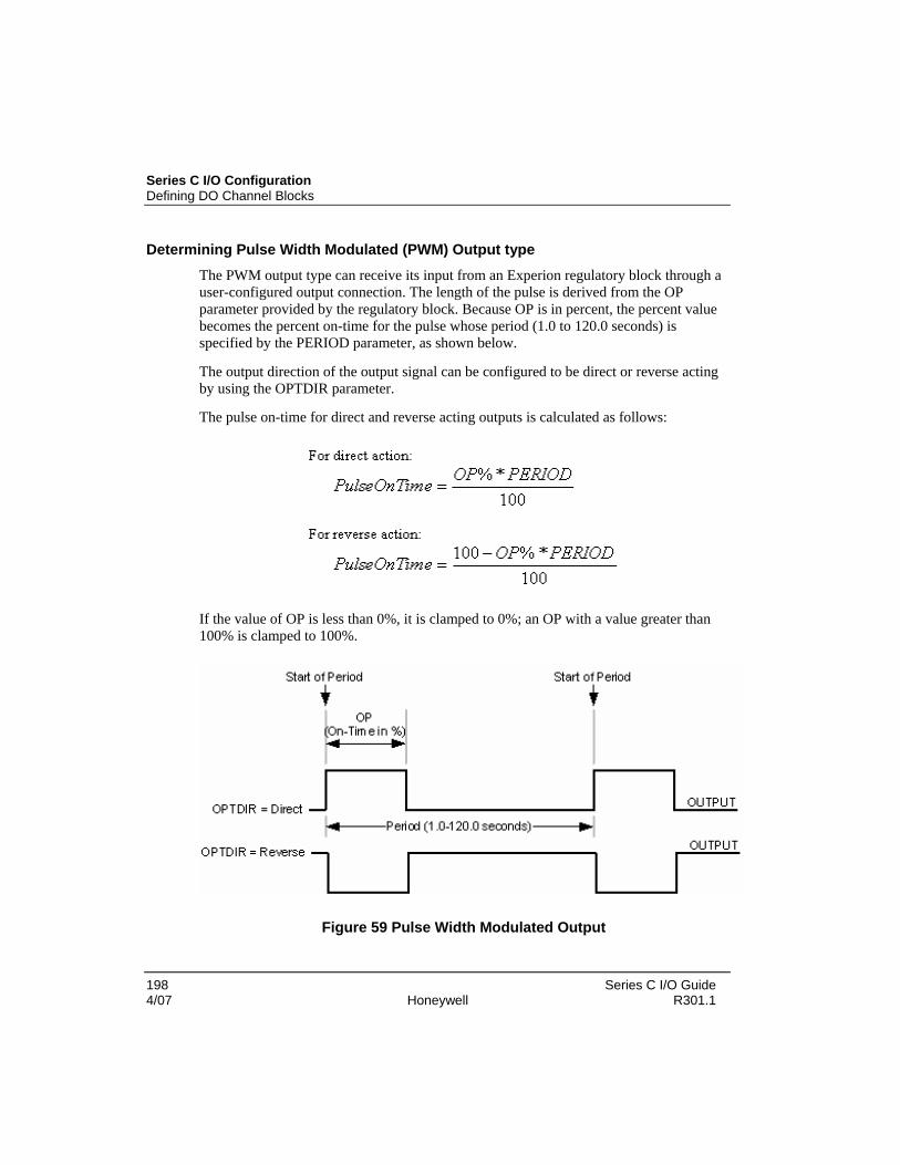
Series C I/O Configuration Defining DO Channel Blocks
198 Series C I/O Guide 4/07 Honeywell R301.1
Determining Pulse Width Modulated (PWM) Output type The PWM output type can receive its input from an Experion regulatory block through a user-configured output connection. The length of the pulse is derived from the OP parameter provided by the regulatory block. Because OP is in percent, the percent value becomes the percent on-time for the pulse whose period (1.0 to 120.0 seconds) is specified by the PERIOD parameter, as shown below.
The output direction of the output signal can be configured to be direct or reverse acting by using the OPTDIR parameter.
The pulse on-time for direct and reverse acting outputs is calculated as follows:
If the value of OP is less than 0%, it is clamped to 0%; an OP with a value greater than 100% is clamped to 100%.
Figure 59 Pulse Width Modulated Output

Defining DO Channel Blocks Determining On-Pulse and Off-Pulse Output type
Series C I/O Guide 199 R301.1 Honeywell 4/07
Determining On-Pulse and Off-Pulse Output type The On-Pulse and Off-Pulse output types can be controlled from:
• a device control block output,
• a logic block output, or
• a RegCtl block (that has been configured for the PosProp algorithm) as determined by the parameter connection.
Pulsed operation (pulse on or pulse-off) can be obtained by linking the output connections to the ONPULSE and OFFPULSE parameters, respectively.
TIP
Standalone DO channels configured for On-Pulse or Off-Pulse are not supported. These blocks must have a parameter connection to an upstream block. SCM writes or other writes using Program access level are not permitted.
The Status Output (SO) setting is impacted by the ONPULSE and OFFPULSE parameters as indicated in the following table.
Table 54 Status Output settings
Parameter Status Output (SO) setting If SO is set to 0.0
ONPULSE On – for specified duration SO is immediately set to OFF
OFFPULSE Off – for specified duration SO is immediately set to ON
To provide consistent and safe behavior, the following occurs when setting DOTYPE to either ONPULSE or OFF PULSE.
Table 55 Setting DOTYPE to ONPULSE or OFFPULSE
If Then
MODE is MAN the ONPULSE and OFFPULSE parameters only accept operator writes. (Program access level writes and all other writes are NOT accepted.)
operator access level writes to SO are accepted and writing SO terminates an active pulse.

Series C I/O Configuration Defining DO Channel Blocks
200 Series C I/O Guide 4/07 Honeywell R301.1
If Then
PTEXECST is ACTIVE changing MODE to CAS sets the output to the quiescent state
Determining Initialization Request Flag
The request to initialize a DO channel is accomplished through the INITREQ or PWMINITREQ parameters.
Table 56 DO channel initialization
The following is set to ON And
INITREQ • Control strategies in Experion cannot manipulate the output.
• Device Control blocks and Position Proportional control algorithms are automatically forced to initialize when outputting to a Digital Output channel.
• When one or more of the following is true
− the module is idle, or
− StandbyMan is Active, or
− MODE is set to MAN, or
− there is a soft failure and the point is not working
PWMINITREQ Control strategies in Experion cannot manipulate the output.
Determining Modes
The MODE parameter determines the operating mode for the channel block. The following operating modes are applicable to the both DO and AO channel blocks:
• Manual (Man) — provides the operator or the program with direct control over the output value of the channel, regardless of any continuous control strategy.
• Cascade (Cas) — data point receives its output value from a primary data point.

Defining DO Channel Blocks Determining Output Verification
Series C I/O Guide 201 R301.1 Honeywell 4/07
TIP
Operators are only permitted to change MODE if MODEPERM is set to Permit and REDTAG is set to off.
Determining Output Verification
Outputs are verified by periodically reading back the value on the output screw and comparing the read back value with the database value. This includes an output wiggle (for the safety system) to prove they are not stuck in any one state.
Determining Over-current protection Digital outputs are protected from inadvertent over-current conditions. If a DO channel draws more current than it should the IOM posts a soft failure and sheds to manual control. Supervisor intervention is required to return the channel to normal operation. Over-current conditions are typically the result of a shorted device or capable.
Comparing parameters between Series C and PMIO that support DO The following parameters are:
• specific to DO and found on various tabs on the DO channel block.
• work identically to the same named PM I/O counterparts.
DO supported parameters for current Series C I/O that work identically to the same named PM I/O parameters
OPTDIR SOINITVAL COMMFAILFL
SO ONPULSE, OFFPULSE PERIOD
SOREADFAIL OP, OPINITVAL


Series C I/O Guide 203 R301.1 Honeywell 4/07
Series C I/O Operations
Overview The following section describes the typical activities that you may be required to perform during normal operations while using Control Builder.
Reviewing the Control Builder icons Series C I/O block icons
After loading the containing CM, the I/O channel block icon appears in the Control Builder monitoring tree. It exists under the containing CM and under the assigned IOM block. In the case of redundancy, a secondary IOM is visible in the monitoring tree.
TIP
The icon’s appearance is based on the ICONSTATE parameter
Table 57 Channel block icons
If icon is . . . Then, it represents . . .
COMM error or CONFIG mismatch error - Primary State
red
Non-redundant
both red
No primary or secondary
front red back yellow
No primary, secondary not synched
RUN - Primary State

Series C I/O Operations Reviewing the Control Builder icons
204 Series C I/O Guide 4/07 Honeywell R301.1
If icon is . . . Then, it represents . . .
green
Non-redundant.
both green
Primary, synchronized
front green back yellow
Primary, secondary not synched
front green back red
Primary, no secondary
IDLE - Primary State
blue
Non-redundant
both blue
Primary, synched
front blue back yellow
Primary, secondary not synched
front blue back red
Primary, no secondary
No Database and IDLE - Primary State

Reviewing the Control Builder icons IOLink icons
Series C I/O Guide 205 R301.1 Honeywell 4/07
If icon is . . . Then, it represents . . .
yellow
Non-redundant
both yellow
Primary, secondary may or may not be synched
front yellow back red
Primary, no secondary
IOLink icons
The following table summarizes the various appearances that an IOLink block icon can assume based on view and current IOLink state. IOLink blocks apply only to the primary or non-redundant IOM block, and do not have matching blocks for secondary IOM.
Table 58 IOLink icons
If Icon is . . . Then, it represents . . .
Project tab
gray
IOLink associated with configured non-redundant or primary IOM.
Monitoring tab
gray/arrow
Control Builder / Control Data Access (CDA) server is currently establishing communication to the IOLink
blue
IOLink is inactive.

Series C I/O Operations Reviewing the Control Builder icons
206 Series C I/O Guide 4/07 Honeywell R301.1
If Icon is . . . Then, it represents . . .
yellow
IOLink is initializing.
green
IOLink is active.
green/asterisks
IOLink is active and uncommissioned devices exist on the H1 network.
red/black exclamation
Communication to the IOLink is unavailable
red/white exclamation
Communication to the IOLink is available, but the IOLink is in a failed state.
Block icons
The following table summarizes the various appearances that a block icon can assume based on view and current block state. The faceplate of the block will vary to reflect the block type.
Table 59 Block icons
If Icon is . . . Then, it represents . . .
Project tab
gray
Block added to Project.
Monitoring tab

Reviewing the Control Builder icons Channel icons
Series C I/O Guide 207 R301.1 Honeywell 4/07
If Icon is . . . Then, it represents . . .
gray/arrow
Control Builder / Control Data Access (CDA) server is currently establishing communication to the block.
green
Block is active
blue
Block is inactive
red/exclamation
Block is offnet. Communications with the block is unavailable.
Channel icons
The following table summarizes the various appearances that a channel icon can assume based on view and current block state.
Table 60 Channel icons
If Icon is . . . Then ICONSTAE parameter value is . . .
yellow Database is invalid
red
Error
blue Block is active

Series C I/O Operations Series C I/O LED Descriptions
208 Series C I/O Guide 4/07 Honeywell R301.1
If Icon is . . . Then ICONSTAE parameter value is . . .
green
Active
yellow/HART Database is invalid and HART is enabled
red/HART Error and HART is enabled
blue/HART Inactive and HART is enabled
green/HART Active and HART is enabled
Series C I/O LED Descriptions The following figure and table identify and describe the LED indicators on the IOM.
Figure 60 Series C I/O LED indicators

Series C I/O LED Descriptions Channel icons
Series C I/O Guide 209 R301.1 Honeywell 4/07
Table 61 I/O LED descriptions
If . . . Is . . . Then, it means that
Power LED Off IOM is not receiving power.
ACTION: Check that module is properly installed or that the IOTA fuse for the module is not blown.
Green IOM is powered.
Status LED Off There is an IOM fault or the LED is bad.
The module is in a hard failure state. In this state the module cannot be used to gather information from or send information to attached field devices.
ACTION: A user must either cycle power to the module or replace the module to correct the failure.
Green IOM operation is Okay.
Primary Run/Idle The module is operating 100% correctly, and the module if commanded to do so; will either gather inputs from the attached field devices or send outputs to the attached field devices. When used in a redundant I/O system, a module with a green LED is often referred to as the primary I/O module.
Green - flashing (toggle once per second)
Primary Run/Idle with Soft Failure The module is operating, but it is operating in a diminished state as one or more soft failures have been identified.
Amber The module is either not configured or operating as a secondary.
Not Configured - The module has not been configured.
Secondary - The module is operating 100% correctly as the secondary module. This does not imply that it is synchronized.

Series C I/O Operations Powering up the IOM
210 Series C I/O Guide 4/07 Honeywell R301.1
If . . . Is . . . Then, it means that
Amber - flashing (toggle once per second)
Secondary with Soft Failure - The module is operating as the secondary module, but it is operating in a diminished state as one or more soft failures have been identified.
Red The device is in a non-standard, transient state and not controlling any part of your plant or process.
Module has just started and power on self test is running.
Red - flashing (toggle once per second)
The device is in a non-standard, transient state and not controlling any part of your plant or process.
Alive, Ready for Firmware Upgrade - The module is ready to receive an update to its internal programming instructions.
Red - fast flashing, (toggle one quarter (1/4) second)
The device is in a non-standard, transient state and not controlling any part of your plant or process.
Alive, Firmware Upgrade in Progress - The module is receiving an update to its internal programming instructions. Do not remove power to the module.
Powering up the IOM Upon power up, the IOM:
• is set to IDLE state with an invalid database (DBVALID = INVALID)
• remains in this state until the IOLINK function block (C300) instructs it to change. This is due to the fact that the C300 contains all of the IOM’s configuration information.
If the IOM was:
• never previously loaded, the IOM:
− remains IDLE with an invalid database.
• previously was loaded, then

Activating a control strategy from the Monitoring tab Starting an IOM
Series C I/O Guide 211 R301.1 Honeywell 4/07
− the C300 reloads the IOM, and restores it to the last state before power down occurred.
Therefore, upon powering up the IOM:
• any previously loaded channel blocks are reloaded and
• the IOM and channel blocks are set to idle, or run as they were previously set before the IOM lost power.
Activating a control strategy from the Monitoring tab Activation of control strategy components from the Monitoring Tab should be performed in the following order to avoid possible load process data alarms.
Table 62 Sequence of activating components – Monitoring tab
Order Component Typical loaded icon in Monitoring tab
1 CEEC300 CEEC300_1
2 IOM AI_HART
3a IOC CM1.AICHANNEL_1
3b HART Enabled IOC HAI_DEVICE_2
4 CM or SCM pidloop
Starting an IOM
Database security is provided to prevent you from starting an IOM that has an invalid database. As part of the IOM load:
• the IOM database is made valid. A checkpoint restore also makes the database valid.

Series C I/O Operations Activating HART
212 Series C I/O Guide 4/07 Honeywell R301.1
• Once the IOM database is valid, you set the IOM Execution State (IOMSTATE) parameter to RUN.
• An IOM cannot be switched from IDLE to RUN unless its database is valid.
Activating HART The Series C I/O’s fundamental AI and AO channel blocks support HART communications protocol, unlike PM I/O. To enable HART, you must assign the channel to a HART IOM, and set HENABLE to TRUE. Other than this difference, the enabled channel is identical to a PM I/O HART enabled channel.
Refer to Enabling HART to review Series C configuration form tabs and parameter availability for HART.
Refer to the HART I/O Implementation Guide for complete HART configuration instructions based on PM I/O.
Assigning a channel to HART – Series C
Prerequisites
• Control Builder is running
• A control module was created
To assign a channel to HART
Step Action
1 Double-click the AI or AO channel block. The channel block configuration form opens.
2 Select the HART Configuration tab from the configuration form.

Activating HART Enabling HART Alarm and Events – Series C
Series C I/O Guide 213 R301.1 Honeywell 4/07
Step Action
3 Select the ENABLE HART (HENABLE parameter).
4 To assign the channel block to a specific device, select a device from the pull-down menu.
5 Click OK to accept changes and close the configuration form. Enabling HART Alarm and Events – Series C
A new selection is added to HART Configuration tab in the channel block, Enable HART Alarm and Events (HALARMENABLE parameter).
Refer to HART Alarms/Events to review the alarms that are available to be displayed on the HART Configuration tab for a channel block.
Disabling HART Alarm and Events
When the parameter HALARMENABLE is disabled (Enable HART Alarm and Events deselected):
• all the existing HART events / alarms from that channel block are disabled
• further generation of the HART alarms / events are terminated
Note: Changing this parameter affects only the HART alarm / event behavior and the LED update of the device status in the HART device status tab happens as usual regardless of the state of HALARMENABLE.
To disable HART Alarm and Events:

Series C I/O Operations IOM configuration values not copied during Block Copy operation
214 Series C I/O Guide 4/07 Honeywell R301.1
Step Action
1 Double-click the AI or AO channel block. The channel block configuration form opens.
2 Select the HART Configuration tab from the configuration form.
3 Deselect the Enable HART Alarm and Events (HALARMENABLE parameter).
IOM configuration values not copied during Block Copy operation
The following subset of the IOM configuration parameter values are not copied during a Block Copy operation.
Uncopied IOM configuration parameters during a Block Copy
IOLINKNAME IOLINKNUM IOMNUM CHNLNAME

Series C I/O Guide 215 R301.1 Honeywell 4/07
Series C I/O Loading
Loading Series C I/O components Experion provides the ability to build control strategies offline, without being connected to the actual controller components. The process of transferring the Control Strategy to the actual working components in the field is called the load operation.
The load operation:
• copies configuration data from the control strategy that is stored in the Engineering Repository Database (ERDB) to the assigned controller component in the system architecture
• assures that the planned system matches the actual one
• confirms that the communication addresses and physical location assignments specified for components through Control Builder configuration match the actual addresses and locations of components in the system
Refer to the Control Building Guide for more information about loading a Control Strategy. See the table below with links to these loading procedures.
Loading strategies
Loading a control strategy
Loading control strategy components
Loading server configuration only Load order guidelines
Load control strategy components from the Project tab in the following order to avoid possible load interaction generated error messages.
Table 63 Sequence of activating components – Project tab
Order Component Typical loaded icon in the Monitoring tab
1 CEEC300
2 C300IOLINK

Series C I/O Loading Loading an IOLINK
216 Series C I/O Guide 4/07 Honeywell R301.1
3 IOM
AI_HART
4 CM or SCM*
Loading an IOLINK IOLINK Load with Contents
The C300 block must be loaded before any assigned IOM blocks. Loading the C300 block automatically loads its associated configured IOLINK function blocks.
Refer to Loading IOLINK in the C300 Controller User Guide for information about loading the C300 block and corresponding IOLINK block.
Upload error conditions
IOLINK problems preventing proper IOLINK loading are found in the Troubleshooting and Maintenance section for:
• IOLINK - loss of communications
• IOLINK - re-establishing communications
Loading the IOM block the first time Loading the IOM block present on the IOLINK
To load the IOM blocks properly:
• The IOM blocks must be loaded prior to loading any Control Modules that contain associated channel blocks. This operation loads all loadable configuration parameters (residing in either the C300 or the IOM device).
• The load returns errors if the C300 or IOM or both are not present.
The figure below shows a simplified graphical representation of what happens during the load operation.

Loading the IOM block the first time Loading the IOM block present on the IOLINK
Series C I/O Guide 217 R301.1 Honeywell 4/07
Figure 61 Loading the IOM block the first time
Loading IOM
Use the following general procedure to load an Input/Output Module (IOM). The load procedure is similar for all I/O signal-handling components.
Prerequisites • Control Builder is running
• This procedure assumes that I/O Modules are installed and capable of communicating with the Server.

Series C I/O Loading Loading the IOM block the first time
218 Series C I/O Guide 4/07 Honeywell R301.1
Considerations
• All illustrations used in the procedure are for example purposes only.
Step Action Result
1 Click desired CEE block icon in Project tab.
Selects and highlights the component.
2 Click Tools->Load with Contents Calls up Load Dialog box

Loading the IOM block the first time Loading the IOM block present on the IOLINK
Series C I/O Guide 219 R301.1 Honeywell 4/07
3 • Be sure load check boxes are checked
for components to be loaded. Click a component to remove/insert a check mark.
• Be sure no Control Module blocks are Checked. Click the OK button.
Initiates the sequential load to the selected components and calls up the load progress dialog.

Series C I/O Loading Loading the IOM block the first time
220 Series C I/O Guide 4/07 Honeywell R301.1
TIP
If errors are detected, they will be displayed in the Load progress dialog and you will be asked if you want to continue the load or cancel, depending on the nature of the error. We suggest that you cancel the load and identify and fix the errors. Each message includes an error code in parentheses. Note the last number in the string. In some cases, more information about the code number may be included in the Control Builder Notifications Reference document in Knowledge Builder.
4 Once the load completes and the dialog box closes, click the Monitoring tab.
IOM icon now appears in Monitoring tab. The default state for a loaded IOM is inactive or color code blue.
5 See the Activating the CEE section in this document to set the IOM to its Run state.
IOM icon turns green when active.
6 Repeat this procedure to install other IOMs.
Loading with the IOM block missing on the IOLINK
IOM blocks can be loaded without the IOM present on the link, but the following occurs:
• Errors are returned on load and the IOM icon appears red in the Monitoring Tab. Refer to Series C I/O block icons to view icon appearance based on current status.
• Since the IOM is responsible for error checking the loaded data, you must either reload the IOM or perform a checkpoint restore when the IOM later appears on the I/O Link.

Loading the IOM block the first time Reloading the IOM block from Project or Monitoring
Series C I/O Guide 221 R301.1 Honeywell 4/07
Reloading the IOM block from Project or Monitoring Reloading an IOM from the Project Tab or the Monitoring Tab behaves in the same manner.
1. the IOM block is loaded first,
2. followed by all channel blocks that have previously been loaded
3. all previously loaded channel blocks appear in the Monitoring Tab of Control Builder
4. Channel blocks that are assigned, but have not been previously loaded, are not loaded.
The figure below shows a simplified graphical representation of what happens during the reload operation.
Figure 62 Reloading the IOM block

Series C I/O Loading Loading the IOM block the first time
222 Series C I/O Guide 4/07 Honeywell R301.1
Reviewing IOM reconfiguration rules
ATTENTION
You are prohibited from altering the IOPTYPE and IOMNUM parameters while the IOM exists on the Monitoring Tab. You can only change them after the IOM is explicitly deleted from the Monitoring Tab.
The following section lists the specific IOM reconfiguration rules.
Table 64 IOM reconfiguration rules
If the IOM is in the RUN state, you:
1. Cannot delete the IOM.
2. Cannot reconfigure non-redundant IOM to redundant IOM.
3. Cannot reconfigure redundant IOM to a non-redundant IOM.
4. Cannot reconfigure the primary IOM to a different location.
5. Cannot reconfigure the secondary IOM to a different location.
6. Cannot change the IOM scan rate.
Note: If you load the IOM and inactivate the IOM as part of the load, you are able to perform items 1 through 6.
If the IOM is NOT in the RUN state, you:
1. Can delete the IOM from the Monitoring Tab (but only if all CMs containing channels of this IOM have been deleted from the Monitoring Tab).
2. Can reconfigure non-redundant IOM to redundant IOM pair.
3. Can reconfigure redundant pair as non-redundant.
4. Can reconfigure the primary IOM to a different location.
5. Can reconfigure the secondary IOM to a different location.
6. Can change the IOM scan rate.

Common I/O block load activities Uploading the I/O block
Series C I/O Guide 223 R301.1 Honeywell 4/07
Common I/O block load activities Uploading the I/O block
Upload of Series C I/O blocks does not differ from the upload of other Experion blocks. All loadable parameter values are read from the IOM and updated in the Monitoring database.
The upload operation uploads data for the selected objects from the controller to the Monitoring Engineering Repository Database (ERDB). Upload of data for the selected objects from the server to the ERDB also can be performed.
Usually, after performing an upload to the database, you should also update the data to Project so that both the Monitoring and the Project databases agree.
Refer to Using Upload command in the Control Building Guide for information about uploading.
Update to Project
Update to Project Series C I/O blocks does not differ from update to Project of other Experion blocks. All loadable parameter values are copied from the Monitoring tab to the Project tab.
Reviewing the Update function
A major part of the hierarchical building, CM/SCM containment allows the user to contain CM(s) or /SCM(s) into another CM.
If a projected CM/SCM is updated to project:
• All its projected parameters are checked to ensure that the projection chain downwards to the origin is valid, which includes the validation of both origin parameters and projected connections.
• Read only connections are not updated to project directly. Only projected connections will be updated.
• And the Update operation fails for any reason, the projected parameter will remain, but the origins of the projected parameter will be emptied.
Using IOM Checkpoint Checkpoint of Series C I/O blocks does not differ from checkpoint of other blocks being checkpointed.

Series C I/O Loading Loading a CM
224 Series C I/O Guide 4/07 Honeywell R301.1
Refer to Checkpoint Replaces Snapshot in the Control Building Guide to review checkpoint information.
Loading a CM Loading the CM the first time
The CM load operation loads the CM block and standard blocks to the assigned CEE function block and load the contained IOC block parameters to the IOM device.
Refer to Loading a CM in the Control Building Guide for information about loading a Control Module and its associated Control Execution Environment (CEE). The load procedure is similar for all control environment related components.
Upload error conditions The following conditions return load errors:
• The C300 is not present.
• The IOM device is not present.
• The IOC’s associated IOM block has not been previously loaded.

Loading a CM Reloading the CM from Project or Monitoring
Series C I/O Guide 225 R301.1 Honeywell 4/07
Figure 63 Loading the CM
Reloading the CM from Project or Monitoring Reloading a CM from the Monitoring Tab or the Project Tab:
• reloads IOC blocks to their associated IOM devices, and
• reloads the standard Experion blocks within the CM to the assigned CEE
Upload error conditions The following conditions return/reload operation errors:
• The C300 is not present.

Series C I/O Loading Loading a CM
226 Series C I/O Guide 4/07 Honeywell R301.1
• The IOM is not present.
• The CM is ACTIVE.
• The IOM’s Execution State is RUN and the IOC block’s Point Execution State is ACTIVE.

Setting Priority IOMs To set the Priority IOM
Series C I/O Guide 227 R301.1 Honeywell 4/07
Setting Priority IOMs To improve control loop latency in Series C I/O Modules, there is an optional selection that supports the IO Link interface and Control Execution Environment (CEE) in the C300 Controller. The Priority IOM option is available for:
• all standard Series C IOMs supported by the C300 Controller and IO Link interface,
• except for the AI-LLMUX
A Priority IOM is designated or configured via the IOM Function Block Form using the modules I/O Link Scan Rate selection. This option applies to all the channels of the IOM. The IOM is added to a list of modules which appear on the associated IOLINK configuration form.
A parameter (NUMPRIORITYIOM – Priority IOMs) on the IOLINK Function Block form (Main Tab) shows the number of configured IOMs with this attribute activated.
To set the Priority IOM
Step Action
1 Double-click the I/O Module in Control Builder treeview. Main tab appears.
2 From I/O Link Scan Rate, select Priority_IOM
3 This completes this task.

Series C I/O Loading Setting Priority IOMs
228 Series C I/O Guide 4/07 Honeywell R301.1
Figure 64 Setting Priority IOM
IOMs designated as Priority_IOM
• consume a relatively larger I/O Link bandwidth than other IOMs
• is given preference within the controller
• Input Process Data from these IOMs is fetched so that it is coordinated with control execution and is triggered at a point that minimizes the latency between data fetch and its use in control algorithms
• Data scanned from an output to a channel on an IOM with thePriority IOM on, is expedited in its passage through the I/O Link interface
The following I/O Link Unit table lists the amount of IO Link bandwidth used for both Priority and normal IOM configuration.
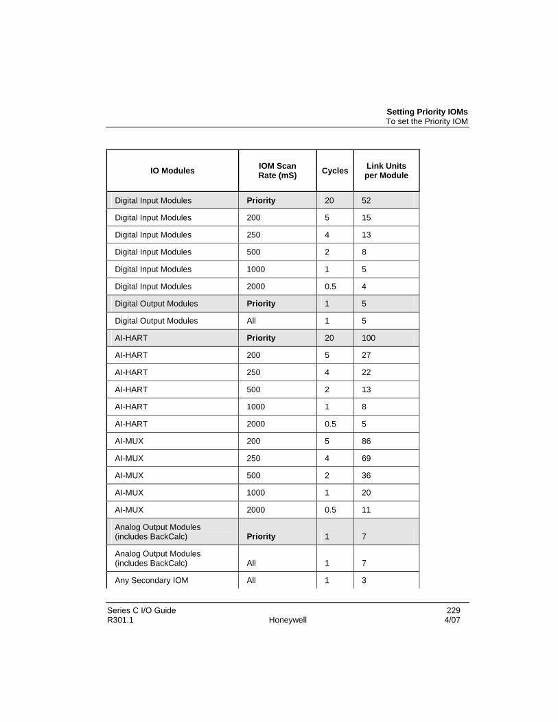
Setting Priority IOMs To set the Priority IOM
Series C I/O Guide 229 R301.1 Honeywell 4/07
IO Modules IOM Scan Rate (mS) Cycles Link Units
per Module
Digital Input Modules Priority 20 52
Digital Input Modules 200 5 15
Digital Input Modules 250 4 13
Digital Input Modules 500 2 8
Digital Input Modules 1000 1 5
Digital Input Modules 2000 0.5 4
Digital Output Modules Priority 1 5
Digital Output Modules All 1 5
AI-HART Priority 20 100
AI-HART 200 5 27
AI-HART 250 4 22
AI-HART 500 2 13
AI-HART 1000 1 8
AI-HART 2000 0.5 5
AI-MUX 200 5 86
AI-MUX 250 4 69
AI-MUX 500 2 36
AI-MUX 1000 1 20
AI-MUX 2000 0.5 11
Analog Output Modules (includes BackCalc) Priority 1 7
Analog Output Modules (includes BackCalc) All 1 7
Any Secondary IOM All 1 3

Series C I/O Loading Setting Priority IOMs
230 Series C I/O Guide 4/07 Honeywell R301.1
SCM Reads per second N/A N/A 0.7
SCM Writes per second N/A N/A 2
AO Connections (Output writes) 50 20 14
AO Connections (Output writes) 100 10 7
AO Connections (Output writes) 200 5 4
AO Connections (Output writes) 500 2 1
AO Connections (Output writes) 1000 1 1
AO Connections (Output writes) 2000 0.5 0
DO SO Connections 50 20 12
DO SO Connections 100 10 6
DO SO Connections 200 5 3
DO SO Connections 500 2 1
DO SO Connections 1000 1 1
DO SO Connections 2000 0.5 0
DO PWM Connections 50 20 30
DO SO Connections 200 5 3
DO SO Connections 500 2 1
DO SO Connections 1000 1 1
DO SO Connections 2000 0.5 0
DO PWM Connections 50 20 30
DO PWM Connections 100 10 15
DO PWM Connections 200 5 8
DO PWM Connections 500 2 3
DO PWM Connections 1000 1 2
DO PWM Connections 2000 0.5 1

Series C I/O Guide 231 R301.1 Honeywell 4/07
Series C I/O Link Fiber Optic Extenders (FOE)
Overview The Fiber Optic module and IOTA board are built exclusively for Honeywell by a third party company. Through the use of a Series C I/O Link Fiber Optic Extender (FOE) module, the ability exists to connect the C300 controller to remote: • Series C I/O and • PM I/O The FOE has the following capabilities: • To connect one local cabinet to two remote I/O sites.
− If more than two remote sites exist, multiple FOE modules may be installed in the local cabinet.
• Has two fiber optic ports sets, FO1 and FO2, − each set having both a receive (Rx) and transmit (Tx) connector.
• An IOLINK connector for connecting to the copper IOL. Note: The same FOE module cannot be used for both types Series C and PM I/O concurrently.
The following FOE connections can be made:
Fiber optic port connections
• Series C: FOE modules to FOE modules
• PM I/O: FOE modules to PM I/O Link Extender
IOLINK (copper) connections
• Series C: FOE modules to copper IOLINK
Fiber Optic Extender assembly
The Fiber Optic Extender assembly consists of components that include the FOE module and the FOE IOTA board, along with the FOE interface cable. This assembly is installed in a control cabinet on vertically mounted carriers, specially designed for Series C control hardware. The following figure shows the features of the FOE and its associated IOTA board.

Series C I/O Link Fiber Optic Extenders (FOE) Overview
232 Series C I/O Guide 4/07 Honeywell R301.1
Figure 65 Fiber Optic Extender assembly
Table 65 FOE module and IOTA summary
Item Description
IOTA board 6-inch
F1 Fuse
24V power Power connection to carrier
Com Ground connection to carrier
FOE Power connector Plug for FOE power cable connection
Fiber Optic Extender module
IOLINK connector IOLINK connector

Overview FOE features
Series C I/O Guide 233 R301.1 Honeywell 4/07
Item Description
Fiber optic ports (2 sets) FO1 – Rx (receive) and Tx (transmit) connectors
FO2 – Rx (receive) and Tx (transmit) connectors
Either set can be used interchangeably.
LED indicators Power and communication indicators for the module FOE features
The following table lists the features available with the Fiber Optic Extender.
Feature Description
Supported family Series C and PM I/O
Topology types Point-to-point A single cable connecting two devices.
Daisy chain Multiple devices connected in a serial manner. Each module acts like “a repeater” allowing greater fiber distances.
Star
Sometimes compared to a “chicken foot”
The electrical ports of two FOE modules are connected to create a “1 in, 3 out” network configuration.
Optical budget 8db min 15db typical
Distance • Between FOEs with standard cables 1.5 km with premium cable 2.0 km
• Daisy chain max 8 km PM I/O 4 km Series C
Module mounting options
• IOTA
• DIN rail (with user supplied power)
Fiber Optic ports 2
Power options • Series C – IOTA
• External power system (DIN rail mounting option)
Power supply options
20 to 30V at 85mA to 74mA max

Series C I/O Link Fiber Optic Extenders (FOE) Overview
234 Series C I/O Guide 4/07 Honeywell R301.1
Feature Description
Ambient temperature
Operating: -20 to +70 degrees C Storage : -20 to +85 degrees C
Corrosives G3 per ISA specification S71.04-1985
Relative humidity 0% to 90% RH
Fiber type Multimode
Fiber core diameter 62.5 mm Fiber cladding diameter 125 mm Connector type ST type
Fiber Optic redundancy
Since both Series C and PM I/O links are redundant, FOE modules are always installed in pairs for possible link A and B connections. Therefore, two independent fiber cables (one for Link A and one for Link B) are required between each local and remote connection.
Hazardous environment This subsection describes the considerations that should be given to the hazardous environment of the FOE assembly and equipment prior to its installation.
FOE assembly certification details The individual elements of the code are explained by reference to the items below. • Class I, Division 2, Groups A, B, C, D • Class I, Zone 2, AEX nA IIC • II 3G EEx nA IIC • ATEX EEx nA IIC T4

FOE Installation Handling components - ESD
Series C I/O Guide 235 R301.1 Honeywell 4/07
FOE Installation The procedures in this guide assume that you have completed all pertinent planning activities as outlined in the Control Hardware Planning Guide.
Handling components - ESD Electrostatic discharge can damage integrated circuits or semiconductors if you touch the connector pins.
ESD HAZARD
Follow these guidelines when you handle a module:
• Touch a grounded object to discharge static potential,
• Wear an approved wrist-strap grounding device,
• Do not touch the connector pins,
• If available, use a static safe workstation Work practices
General Before installation, follow these work practices when performing general tasks: • Ensure that all installation work is to be carried out in accordance with local
standards, codes of practice and site regulations and any other special requirements stated in this manual.
• Check that all module functions are correct for the application • Take care to avoid damaging the pins at all connector interfaces • Ensure that AC mains supplies have been isolated. • It is recommended that some form of mechanical assistance is used for lifting and
supporting the enclosure when installing it.
Hazardous areas This subsection describes the considerations that should be given to Zone 2 and Division 2 hazardous environments of the equipment prior to its installation.
Work activities in a Zone 2 and Division 2 hazardous area are restricted in order to avoid ignition of explosive gas/air mixtures.

Series C I/O Link Fiber Optic Extenders (FOE) FOE Installation
236 Series C I/O Guide 4/07 Honeywell R301.1
Operations
The equipment must only be installed, operated and maintained by trained competent personnel.
Checking and Maintenance
The installation and maintenance must be carried out in accordance with all appropriate international, national and local standard codes of practice and site regulations in accordance with the instructions contained in this manual.
Installation The FOE product: • is an electrical apparatus and must be installed in the hazardous area in accordance
with the requirements of the EC Type Examination Certificate • has no exposed parts of the apparatus that produce excessive surface temperature,
infrared, electromagnetic, ionizing radiation or non-electrical dangers • must not be subjected to mechanical and thermal stresses in excess of those
permitted in the certification documentation, this manual and the product specification
• must not be installed in a position where it may be attacked by aggressive substances and must be protected from excessive dust.

Component mounting sequence Mounting the FOE module onto the IOTA
Series C I/O Guide 237 R301.1 Honeywell 4/07
Component mounting sequence
Proper mounting sequence
It is required that the installation be done in the following sequence: 1. Mount the FOE module onto the IOTA 2. Connect the FOE module’s power cable to the module 3. Remove the IOTA F1 fuse. 4. Mount the FOE module assembly to the carrier 5. Connect the I/O link cable. 6. Re-install the IOTA F1 fuse.
Mounting the FOE module onto the IOTA Prerequisites:
It is required to attach the FOE module to the IOTA prior to its mounting to the carrier. The following also needs to be established:
• All wiring and pre-fabricated cables are available and labeled as applicable.
To mount the module onto the IOTA:
Step Action
1 Align the FOE screws (located on the flange) with the holes on the IOTA.
2 Tighten the four screws that attach the base of the FOE module to the IOTA board (using a Phillips screwdriver).
3 Connect the power cable from the IOTA board to the connector at the bottom of the module.
4 This completes the procedure. Connecting the FOE module’s power cable to the module
Typically, the FOE power cable does not require any adjustment or maintenance. If there is a power issue with the FOE module, a loose or disconnected power cable may be the cause. If the power cable is damaged the IOTA board requires replacing.
Prerequisite:
Before connecting the FOE module’s power cable to the module: • Refer to FOE connection rules.

Series C I/O Link Fiber Optic Extenders (FOE) Component mounting sequence
238 Series C I/O Guide 4/07 Honeywell R301.1
To reconnect the FOE power cable to the module:
Step Action
1 Ensure the power cable connector is properly aligned with the plug on the module.
2 Press the plug firmly into the connector.
3 Using a small slotted screwdriver, fasten the screws on the cable connector to the FOE module.
4 This completes the procedure. Removing the IOTA F1 fuse
ATTENTION
Prior to installing or servicing the FOE assembly (FOE module on the IOTA) to the carrier, the F1 fuse needs to be removed. After mounting the FOE assembly to the carrier and securing the power and ground screws, the F1 fuse can be re-installed.
To remove the IOTA F1 fuse:
Step Action
1 Using a small slotted screwdriver, place the tip into the slot on the fuse cap (The cap is the fuseholder).
2 Rotate the cap counter clockwise, a quarter-turn. Remove the cap that also holds the fuse.
Place the fuse aside in a stable location for reuse.
3 This completes the procedure.

Component mounting sequence Mounting the FOE module/IOTA assembly to the carrier
Series C I/O Guide 239 R301.1 Honeywell 4/07
Mounting the FOE module/IOTA assembly to the carrier Prerequisite:
Before installing the FOE module/IOTA assembly in the cabinet, ensure that:
• All wiring and pre-fabricated cables are available.
ATTENTION
Prior to installing or servicing the FOE assembly (FOE module on the IOTA) to the carrier, the F1 fuse needs to be removed. After mounting the FOE assembly to the carrier and securing the power and ground screws, the F1 fuse can be re-installed.
To mount the FOE module/IOTA assembly to the carrier:
Step Action
1 Ensure the F1 fuse is removed.
2 Select the desired mounting location on the carrier and align the mounting holes in the IOTA with the screw-hole locations on the carrier.
6 inch IOTA board 4 mounting screws
Be sure the component side of the IOTA is facing up.
3 Using a #2 Phillips screw driver, secure the FOE assembly to carrier.
4 Tighten the two power screws, connecting the IOTA board to the vertical bus bars on the channel carrier assembly:
• +24 V power screw
• Com ground screw
5 This completes the procedure. Connecting the IOLINK interface cable to the FOE module
ATTENTION
The lOLINK interface cable should be connected to the FOE module before it is powered up.
Prerequisite:

Series C I/O Link Fiber Optic Extenders (FOE) Component mounting sequence
240 Series C I/O Guide 4/07 Honeywell R301.1
Before connecting the FOE module’s IOL interface cable to the module: • Refer to FOE connection rules.
To connect the IOLINK interface cable to the FOE module:
Step Action
1 Ensure the IOLINK interface cable connector is properly aligned with the connector on the FOE module.
2 Press plug firmly into the connector.
3 Fasten the screws on the cable connector to the FOE module.
4 This completes the procedure. Re-installing the IOTA F1 fuse
ATTENTION
Prior to installing or servicing the FOE assembly (FOE module on the IOTA) to the carrier, the F1 fuse needs to be removed. After mounting the FOE assembly to the carrier and securing the power and ground screws, the F1 fuse can be re-installed.
To re-install the IOTA F1 fuse:
Step Action
1 Place the fuse in the fuseholder and insert it back into the fuse container on the IOTA board.
2 Tighten the fuse cap rotating it clockwise a quarter-turn, using a small slotted screwdriver.
3 This completes the procedure.

Component mounting sequence Connecting the fiber optic cables to the FOE module
Series C I/O Guide 241 R301.1 Honeywell 4/07
Connecting the fiber optic cables to the FOE module
ATTENTION
Unused optical ports should always have protective covers on them to prevent dust and other contaminants from accumulating on the glass fiber optic interfaces.
Fiber-optic ST-type connectors may be removed, or replaced, while active and in a Zone 2 or Division 2 hazardous area.
Prerequisite:
Before connecting the FOE module’s power cable to the module: • Refer to FOE connection rules.
To connect the FOE cables to the FOE module:
Step Action
1 Ensure the terminal caps are removed from the ST optical ports on the FOE module. If the terminal caps are still attached, rotate the cap counter-clockwise to disengage the cap from the locking tab.
2 Insert the ST connector of the fiber optic cable onto the proper FOE port.
Top FO1 – Rx (receive) and Tx (transmit) connectors
Bottom FO2 – Rx (receive) and Tx (transmit) connectors
FOE Cable Guidelines
• FO1 and FO2 ports may be used interchangeably. However, the Rx and Tx connections of a given cable must be terminated on the same port.
• The cable end attaches to Rx on one module and to the Tx on the other module.

Series C I/O Link Fiber Optic Extenders (FOE) Component mounting sequence
242 Series C I/O Guide 4/07 Honeywell R301.1
Step Action
Note: The FO1 and FO2 cable connections to the modules are done in the following manner:
3 This completes the procedure. FOE connection rules
ATTENTION
Prior to installing or servicing the FOE assembly (FOE module on the IOTA) to the carrier, the F1 fuse needs to be removed. After mounting the FOE assembly to the carrier and securing the power and ground screws, the F1 fuse can be re-installed.
The power and cable connections to the FOE are allowable under the following conditions:
Connecting and
discounting Rule
Power Removing the IOTA F1 fuse powers down the FOE.
IOLINK cable under power
The IOLINK cable between the C300 and the FOE module can be removed or replaced while under power only after verifying that the location is a non-hazardous area.
Fiber optic cables under power
Fiber-optic ST-type connectors may be removed, or replaced, while active and in a Zone 2 or Division 2 hazardous area.
LED indicators
The following table defines the LEDs located on the Fiber Optic Extender module.
Table 66 FOE LED descriptions

Component mounting sequence LED indicators
Series C I/O Guide 243 R301.1 Honeywell 4/07
Indicator Color LED off LED on
Green Power fail Power OK
Yellow Communication signal not present
Communication signal present on Rx channel
Yellow Communication signal not present
Communication signal present on Rx channel
Yellow Communication signal not present
Communication signal present on RS485 port.

Series C I/O Link Fiber Optic Extenders (FOE) Defining the Fiber Optic topology
244 Series C I/O Guide 4/07 Honeywell R301.1
Defining the Fiber Optic topology There are three different FOE topologies supported. These topologies are: • Daisy chain • Tree • Star
ATTENTION
The following figure is an example how the FOE can be deployed in a variety of topologies for both the Series C and PM I/O environment. This graphic is not to depict any restrictions with regards to FOE capacity or cable length.
Figure 66 Example of possible FOE usage

Defining the Fiber Optic topology FOE capacity
Series C I/O Guide 245 R301.1 Honeywell 4/07
FOE capacity The FOE can be deployed and combined in a variety of topologies. The following list can be used as a general guideline of supported environments and FOE capacities.
Environment Hardware Capacity
Series C I/O Cable length 4 km max – each FOE counts as .25 km
PM I/O Cable length 8 km max – each FOE counts as .5 km Required hardware
Depending on your topology, the following Series C hardware is required to achieve remote I/O accessibility:
Component • Fiber Optic Extender IOTA • Fiber Optic Extender module • Fiber optic cables FOE interface cables – 0.5M length for both Series C & PM I/O • Gray (pair) for IOL1 • Violet (pair) for IOL2
Fiber Optic Extender interface cable
The Series cable has a different electrical keying than its PM I/O counterpart. Therefore, the specific cable type must be used for each I/O family.
ATTENTION
The proper interface cable must be used for either the Series C or the PM I/O topology. Use of the incorrect cable will result in faulty and/or corrupted IOL communications.
The fiber link is a passive subsystem and is essentially transparent to the system operation. It does not increase or decrease traffic or impact other capabilities of the I/O system. Also the following designations occur for these cables:
Cable Cable color A-link tab color B-link tab color
IOL1 Gray Yellow green
IOL2 violet Yellow green

Series C I/O Link Fiber Optic Extenders (FOE) Defining the Fiber Optic topology
246 Series C I/O Guide 4/07 Honeywell R301.1
Fiber optic cable – length factors
The maximum run of the fiber optic cables is limited by the optical power budget of 8db. Standard cables support 1.5 km while premium cable supports 2 km runs.
FOE topologies
Daisy chain topology
A daisy chain topology allows the remote I/O connection to be extended and can be utilized several times - provided that maximum flight delay times of data passing between the C300 controller and I/O are not exceeded.
When Series C daisy chaining, the electrical port requires no interface cable to be attached. This applies if:
• daisy chaining Series-C link traffic, and
• I/O is not present at the repeating location.
When PM I/O daisy-chaining, an interface cable must always be connected to the electrical port. This is because the cable keys the FOE for the PM mode of operation
A repeater function also extends the remote I/O similar to the daisy chain technique, but relies on the optical ports of two FOE modules to provide the interconnection.
Star topology
This technique uses interconnected FOEs to allow a single incoming fiber cable to star to multiple remote sites. It can also be referred to as a chicken-foot topology.
Maximum flight delay times
The I/O link communication protocol imposes a constraint between the C300 controller and the most distant I/O location, known as maximum flight delay time. This places a limit on the combined number of FOEs, and cumulative fiber cable length permitted in any IOL path. This constraint varies for:
Series C – maximum cable length is 4km
Each FOE (except for the local site) subtracts an additional .25km
PM I/O – maximum cable length is 8km

Defining the Fiber Optic topology Fiber optic budget considerations
Series C I/O Guide 247 R301.1 Honeywell 4/07
Each FOE (except for the local site) subtracts an additional .50km Fiber optic budget considerations
ATTENTION
Fitting terminations to fiber optic cable requires special equipment and techniques. In order to obtain the best results, a trained person should perform this operation in accordance with the manufacturer’s instructions. For these reasons, the following installation instructions do not include detailed procedures for this process.
Testing of the quality (loss) of the terminations should be carried out at each stage.
Standard I/O link extender maximum cable span calculation
The following calculation MUST be used to ensure that the number of planned splices and the cable choice supports the necessary cable span distance.
The maximum cable span calculation (in km) is as follows:
Max Span = (Available Optical Power – Losses in Splices)/(Max Loss per Cable Type)
The calculations or values for each of the above variables are described below.
Available standard I/O link extender optical power The available optical power calculation is as follows:
Transmit Power - Minimum Receiver Sensitivity - Power Loss Over Time =
Available Optical Power
where for a Standard I/O Link Extender:
Transmit Power = - 16.0 dB Minimum Receiver Sensitivity = - 24.0 dB Power Loss Over Time = 2.5 dB
Example calculation for a Standard I/O Link Extender using 62.5 micron cable: (- 16.0 dB) - (- 24.0 dB) - (2.5 dB) = 5.5 dB Available Optical Power
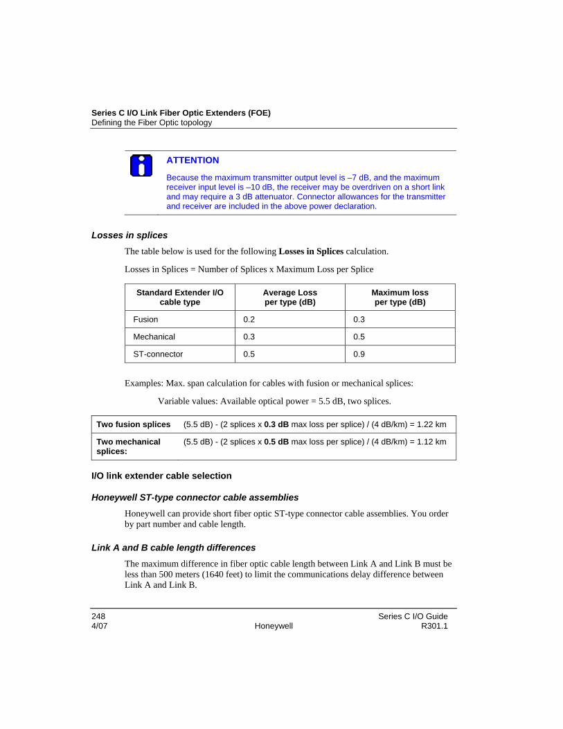
Series C I/O Link Fiber Optic Extenders (FOE) Defining the Fiber Optic topology
248 Series C I/O Guide 4/07 Honeywell R301.1
ATTENTION
Because the maximum transmitter output level is –7 dB, and the maximum receiver input level is –10 dB, the receiver may be overdriven on a short link and may require a 3 dB attenuator. Connector allowances for the transmitter and receiver are included in the above power declaration.
Losses in splices
The table below is used for the following Losses in Splices calculation.
Losses in Splices = Number of Splices x Maximum Loss per Splice
Standard Extender I/O cable type
Average Loss per type (dB)
Maximum loss per type (dB)
Fusion 0.2 0.3
Mechanical 0.3 0.5
ST-connector 0.5 0.9
Examples: Max. span calculation for cables with fusion or mechanical splices:
Variable values: Available optical power = 5.5 dB, two splices.
Two fusion splices (5.5 dB) - (2 splices x 0.3 dB max loss per splice) / (4 dB/km) = 1.22 km
Two mechanical splices:
(5.5 dB) - (2 splices x 0.5 dB max loss per splice) / (4 dB/km) = 1.12 km
I/O link extender cable selection
Honeywell ST-type connector cable assemblies
Honeywell can provide short fiber optic ST-type connector cable assemblies. You order by part number and cable length.
Link A and B cable length differences
The maximum difference in fiber optic cable length between Link A and Link B must be less than 500 meters (1640 feet) to limit the communications delay difference between Link A and Link B.

Defining the Fiber Optic topology I/O link extender cable selection
Series C I/O Guide 249 R301.1 Honeywell 4/07
Allowable standard I/O Link extender cable signal loss
The Standard I/O Link Extender cable: • Must have a total signal loss equal to or less than -5.5 dB at a wavelength of 850
nanometers. • Fiber loss is measured at 22degrees C ±3 degrees and is usually stated as a mean
value. • Individual fiber losses may be as much as 25% greater than the mean.

Series C I/O Link Fiber Optic Extenders (FOE) FOE recommended spares
250 Series C I/O Guide 4/07 Honeywell R301.1
FOE recommended spares Spare parts
The following table provides replacement parts, or parts that you may want to keep on hand for backup.
Table 67 Recommended spare parts
Part name Part number Description
Fiber Optic Extender module
Fiber optic Extender module
8937-HN Fiber Optic Extender module 2km CC-PFE221 – Honeywell model number
Fiber Optic Extender IOTA
Fiber Optic Extender IOTA
8939-HN 6 inch FOE IOTA CC-TFE021 – Honeywell model number
Cables
CC-KFSGR5 0.5M FOE to Series C I/O link interface cable - Gray SC IOL cable
CC-KFSVR5 0.5M FOE to Series C I/O link interface cable - Violet
CC-KFPGR5 0.5M FOE to PM I/O link interface cable - Gray PM IOL cable
CC-KFPVR5 0.5M FOE to PM I/O link interface cable - Violet
Fuses
Description Part number Quantity Reference designator
Function
Fuse Two replacement options.
• 216.250P Littelfuse
• S501-250-R Cooper Bussman
1 F1 Power to module electronics

FOE Maintenance FOE Repair
Series C I/O Guide 251 R301.1 Honeywell 4/07
FOE Maintenance Remote I/O requires a minimum of maintenance. A regular inspection program is advised, but the frequency of inspections depends largely upon the environmental conditions in which the equipment normally operates.
The following should be periodically checked: • all cables and wires attached to the FOE module • evidence of any tampering or unauthorized modifications
FOE Repair The FOE module and IOTA cannot be repaired by the user and must be replaced with an equivalent certified product. Repairs should only be carried out by the manufacturer.
Replacing the IOTA F1 fuse Refer to the FOE recommended spares section in this document for the proper replacement fuse to be used.
ATTENTION
Prior to installing or servicing the FOE assembly (FOE module on the IOTA) to the carrier, the F1 fuse needs to be removed. After mounting the FOE assembly to the carrier and securing the power and ground screws, the F1 fuse can be re-installed.
To replace the IOTA F1 fuse:
Step Action
1 Using a small slotted screwdriver, place the tip into the slot on the fuse cap (The cap is the fuseholder).
2 Rotate the cap counter clockwise, a quarter-turn. Remove cap that also holds the fuse.
3 Replace the fuse in the fuseholder and insert back into the fuse container on the IOTA board.
4 Tighten the fuse cap rotating it clockwise a quarter-turn using the screwdriver.
5 This completes the procedure.

Series C I/O Link Fiber Optic Extenders (FOE) FOE Maintenance
252 Series C I/O Guide 4/07 Honeywell R301.1
Replacing the FOE module on the IOTA If the FOE module needs replacing or requires mounting on the IOTA, do the following.
Prerequisite: • the IOTA has been previously removed or is missing from the IOTA board
ATTENTION
Prior to installing or servicing the FOE assembly (FOE module on the IOTA) to the carrier, the F1 fuse needs to be removed. After mounting the FOE assembly to the carrier and securing the power and ground screws, the F1 fuse can be re-installed.
To replace the FOE module on the IOTA:
Step Action
1 Align the FOE screws (located on the flange) with the holes on the IOTA.
2 Tighten the four screws that attach the base of the FOE module to the IOTA board (using a small Phillips screwdriver).
3 Connect the power cable from the IOTA board to the connector at the bottom of the module.
4 This completes the procedure. Removing the FOE assembly from the carrier
If the FOE assembly needs replacing and therefore, requires removal from the carrier, do the following.
ATTENTION
Prior to installing or servicing the FOE assembly (FOE module on the IOTA) to the carrier, the F1 fuse needs to be removed. After mounting the FOE assembly to the carrier and securing the power and ground screws, the F1 fuse can be re-installed.

FOE Maintenance Cable considerations
Series C I/O Guide 253 R301.1 Honeywell 4/07
To remove the FOE assembly from the carrier:
Step Action
1 Using a #2 Phillips screwdriver, loosen the two power screws, connecting the IOTA board to the vertical bus bars on the channel carrier assembly:
• +24 V power screw
• Com ground screw
2 Disconnect the IOLINK cable from the end that attaches to either the C300 or I/O IOTA.
3 Remove the FOE assembly from the carrier using a #2 Phillips screwdriver.
4 This completes the procedure. Cable considerations
Hazardous Area Cable Requirements
For U.S. installations, section 770-53 (d) of NEC Article 770 states that "Cables installed in hazardous (classified) locations shall be any type indicated in Table 770-53." This table is reproduced below.
Cable type Permitted substitutions
OFNP None
OFCP OFNP
OFNR OFNP
OFCR OFNP, OFCP, OFNR
OFNG, OFN OFNP, OFNR
OFCG, OFC OFNP, OFCP, OFNR, OFNG, OFN
The cable types are described in the following table:
Cable marking
Cable type
Reference (NEC Article 770)
OFNP Nonconductive optical fiber plenum cable 770-51(a) and 770-53(a)

Series C I/O Link Fiber Optic Extenders (FOE) FOE Maintenance
254 Series C I/O Guide 4/07 Honeywell R301.1
Cable marking
Cable type
Reference (NEC Article 770)
OFCP Conductive optical fiber plenum cable 770-51(a) and 770-53(a)
OFNR Nonconductive optical fiber riser cable 770-51(b) and 770-53(b)
OFCR Conductive optical fiber riser cable 770-51(b) and 770-53(b)
OFNG Nonconductive optical fiber general-purpose cable 770-51(c) and 770-53(c)
OFCG Conductive optical fiber general-purpose cable 770-51(c) and 770-53(c)
OFN Nonconductive optical fiber general-purpose cable 770-51(d) and 770-53(c)
OFC Conductive optical fiber general-purpose cable 770-51(d) and 770-53(c)
Nonconductive fiber optic cable is defined as cable containing no metallic members and no other electrically conductive materials.
Conductive fiber optic cable is defined as cable containing non-current-carrying
conductive members such as: metallic strength members, metallic vapor barriers and metallic armor or sheath.
Cable jacket Building Code Requirements
Building code requirements frequently do not allow cables with polyethylene jackets. Jackets of polyvinyl chloride are frequently restricted to conduits, while fluoropolymer or other approved jacked material is required for use in cable trays and air plenums. Cable with suitable jacket material must be selected for the application.
Cable temperature variation considerations
Where ambient temperature variations are 20°C or greater on a daily basis, the life of the fibers can be significantly reduced. In applications where the ambient temperature is not controlled, loose buffered cable must be specified.
Spare fiber cable recommendation
A minimum of two cable fibers is required for each link, one for transmit and one for receive. The following characteristics apply to fiber optic cable spares: • As insurance against future damage, such as fiber breakage, or encountering
excessive loss in any one fiber, the inclusion of spare fibers is recommended. 100% cable replacement is recommended.

FOE Maintenance Cable considerations
Series C I/O Guide 255 R301.1 Honeywell 4/07
• Indoor 62.5 Micron Cable is used for indoor cabling. Indoor cables are available with 2, 4, or 6 fibers.
• Outdoor 62.5 Micron Cable is used for outdoor cabling. Outdoor aerial and direct burial cables are available with 4, 6, or 8 fibers.

Series C I/O Link Fiber Optic Extenders (FOE) FOE Troubleshooting
256 Series C I/O Guide 4/07 Honeywell R301.1
FOE Troubleshooting This section identifies some common problems with the Fiber Optic Extender and describes how you might fix them.
ATTENTION
Prior to installing or servicing the FOE assembly (FOE module on the IOTA) to the carrier, the F1 fuse needs to be removed. After mounting the FOE assembly to the carrier and securing the power and ground screws, the F1 fuse can be re-installed.
The Fiber Optic Extender does not exhibit a large number of errors that are directly attributed to the FOE. Knowledge of your system’s setup is critical in determining the potential source of disruption to communication and process. Failures beyond the point of the FOE may indicate a functionality issue with the FOE.
Loss of power The Fiber Optic Extender module has lost power supply communications to remote I/O has failed.
Diagnostic Check Power to the Fiber Optic Extender module has failed. Communications
to remote I/O has been discontinued.
• System Alarm Summary alarms displayed
• Green LED on FOE module is off.
Cause 1 The FOE power cable from the module to the IOTA has become loose or disconnected.
Solution 1 Check the cable from the FOE module to the FOE IOTA and ensure that it is firmly connected.
Cause 2 Power fuse is blown on the FOE IOTA.
Solution 2 If there is no obvious reason for the failure of the fuse (F1) on the FOE IOTA, then the FOE must be suspected of having a fault and must be replaced and its functionality checked in a non-hazardous area. If the FOE is known not to be the reason for the failure of the fuse, then it is permitted to replace the fuse without isolating the power to the IOTA.
Cause 3 C300 controller has lost power.
Solution 3 Refer to C300 “Loss of power” instructions.

FOE Troubleshooting Loss of communication
Series C I/O Guide 257 R301.1 Honeywell 4/07
Diagnostic Check Power to the Fiber Optic Extender module has failed. Communications to remote I/O has been discontinued.
• System Alarm Summary alarms displayed
• Green LED on FOE module is off.
Cause 4 Main power source has been disconnected or shut down either manually or temporarily by brownout or blackout condition.
Solution 4 Re-connect the main power source or turn it On or wait for temporary brownout or blackout condition to pass.
Cause 5 The 24 Vdc power supply failed or power cable has been disconnected or failed.
Solution 5 Replace the 24 Vdc power supply or re-connect/replace the power cable. Loss of communication
The remote I/O communication is lost or behaving erratically. The Fiber Optic Extender module yellow LEDs are not on/blinking.
Diagnostic Check Remote I/O communications is lost.
• System Alarm Summary alarms displayed
• Green LED on FOE module is on.
• Yellow LED on FOE module is off
• Erratic behavior of I/O connections/communications beyond a specific FOE.
Cause 1 Possible loose cable connection:
Solution 1 Check the following cable connections:
• IOLINK CABLE
− From C300 to FOE module IOLINK connector
• Fiber optic cable
− From FOE module to FOE module
− From FOE module to PM I/O Link Extender card
Cause 2 Power is lost to the FOE module, C300 controller or entire control cabinet.

Series C I/O Link Fiber Optic Extenders (FOE) FOE Troubleshooting
258 Series C I/O Guide 4/07 Honeywell R301.1
Diagnostic Check Remote I/O communications is lost.
• System Alarm Summary alarms displayed
• Green LED on FOE module is on.
• Yellow LED on FOE module is off
• Erratic behavior of I/O connections/communications beyond a specific FOE.
Solution 2 Refer to “Loss of power” troubleshooting information.
Cause 3 FOE module is malfunctioning.
Solution 3 Replace FOE module.

Series C I/O Guide 259 R301.1 Honeywell 4/07
Series C I/O Migrating from PMIO to Series C I/O
Determining Series C I/O vs. PMIO functionality Label
The Series C I/O family is a replacement for Honeywell’s PM I/O family. As such, many PM I/O concepts are directly carried forward into Series C I/O. Some notable concepts that are NOT directly carried forward are included in the table below.
Table 68 Comparing Series C and PM I/O functionality
Topic PM I/O supported
Series C I/O supported
Experion Yes Yes
TPS Yes No
IOLINK connection Yes
Through C200 controller and IOLIM or C300 controller
Yes
C300 controller only
PM I/O and Series C I/O cannot exist on the same IOLINK
PM I/O and Series C I/O cannot exist on the same IOLINK
Nomenclature IOP I/O Processor
IOM I/O Module
Deriving a physical address Uses file and card concept Address derived from IO Number from IOTA
Can be configured as redundant or non-redundant
Yes – most can Yes – most can.
Low Level Analog Input MUX IOM can be configured only as non-redundant.
IOTA slots Any combination allowed Upper – always IOMA
Lower – always IOMB
Non-redundant configurations only IOMA can be used.
Enumeration sorting By ordinal value Alphabetically, unless

Series C I/O Migrating from PMIO to Series C I/O Determining Series C I/O vs. PMIO functionality
260 Series C I/O Guide 4/07 Honeywell R301.1
Topic PM I/O supported
Series C I/O supported
otherwise stated.
Firmware remotely downloaded in Experion
No Yes
HART I/O PMIO supported four separate AI, AO, HAI and HAO channel blocks. AI and AO channel blocks could not be configured for HART operation
In Series C I/O, AI and AO channel blocks can be configured for HART operation. No separate HAI and HAO channel blocks will be supported.
HART 5.0 compliant Yes Yes
HART 6.0 compliant No Yes
Detect/sense open sensor (open wire)
No Yes. High Level Analog, and DI 24V detect open wire. The HART Analog Output IOM detects open wire by virtue of its analog read back check.
FAILOPT or FAULT[*] FAILOPT is a IOP-wide configuration, making it same to all channels in an IOP
In Series C FAILOPT is replaced with the following:
• FAULTOPT, and
• FAULTVALUE
this can be set individually for every output channel.
LLMUX maximum channels 32 64
Supports the concept of PNTFORM (FULL and COMPONENT points)
Yes No The most powerful FULL point features have been incorporated into Series C I/O channel blocks.
Specifications for the availability of HART data, including availability through an IOM switchover are tightened for Series C I/O.

Migrating channels blocks from PMIO to Series C I/O Label
Series C I/O Guide 261 R301.1 Honeywell 4/07
Migrating channels blocks from PMIO to Series C I/O
Parameter mapping PM I/O channels to Series C I/O channels
The high-level user-related configuration and operational differences between PM I/O channels and Series C I/O channels are best seen by examining differences between the parameters for each I/O family.
With the exception of HART based channels, PM I/O uses a single channel block with a multitude of options and tabs to represent channels defined on multiple IOPs. For example:
• PM I/O uses the same AICHANNEL block for channels contained within HLAI, LLAI, LLMUX, RHMUX and STIMV IOPs.
• Series C I/O has the ability to morph an AICHANNEL block for use with many IOMs types. Tabs of the parameter form that are not used for some IOM types are hidden.
Series C I/O HART enabled channels now can be morphed to/from a standard AI or AO channel block. The following also applies:
• On an IOP switchover, HART digital data could take as long as 48 seconds to be refreshed.
• For Series C IOM, HART digital data is refreshed within twice the module’s SCANRATE time.
Table 69 Comparing Series C and PM I/O parameters
PM I/O IOC parameter
Series C I/O IOC parameter
Change from PM I/O channel/comment
SENSRTP SENSRTP
PVCHAR PVCHAR
A list of valid values for the particular AI channel type is always provided. You are NEVER shown or allowed to select an invalid value for any particular AI channel type.
Refer to the Control Builder Parameter Reference guide for parameter specific information.
PNTTYPE
(removed) Parameter is deleted. Some TPS “FULL” point parameters are now part of Series C I/O channel blocks.
SLWSRCRCID (removed) Parameter was deleted. SLIDEWIRE sensor type

Series C I/O Migrating from PMIO to Series C I/O Migrating channels blocks from PMIO to Series C I/O
262 Series C I/O Guide 4/07 Honeywell R301.1
PM I/O IOC parameter
Series C I/O IOC parameter
Change from PM I/O channel/comment
is not supported in Series C I/O. SLIDEWIRE sensor type was not implemented in PM I/O. However, the parameter was defined.
PVRAWHI PVRAWHI
PVRAWLO PVRAWLO
These parameters are valid only for AICHANNELS that exist on AI-LLMUX IOMs.
HPVCHAR PVCHAR The PM I/O functionality provided by setting HPVCHAR to “Device Range” is provided by the setting PVCHAR to “Device Range”.
ACCEPTRNG ACCEPTRNG The text on this push button changed from “Accept Device Ranges” to “Sync. Device and PV Ranges”.
HPVMISM HPVMISM While HPVMISM generated an alarm in PM I/O, it is a simple boolean flag in Series C I/O.
FAILOPT FAULTOPT FAULTVALUE FAULTST
In PM I/O, FAILOPT is a read/write parameter for IOP blocks. Also, the FAILOPT value applies to all channels on that IOP and FAILOPT is a read only parameter for channel blocks. In Series C I/O, each channel has its own fault option and a set of “fault” related parameters.
Additionally, there are a significant number of enhancements related to handling AO and DO channel faults. When migrating from PMIO you are encouraged to obtain a thorough understanding of the AO and DO channels before migrating to Series C I/O.
(not implemented)
HDYNCC HDYNST HMAXDEVVARS HNCFGCHG HNSMMINPRE HSLOTCC HSLOTST
PM I/O does not support HART version 6.0. Series C I/O supports these parameters for HART version 6.0.
PIUOTDCF OWDENBL Made OWDENBL the consistent name for enabling Open Wire Detection Enable. Also OWDENBL is valid for DI channels on DI-24 IOMs and AI channels.
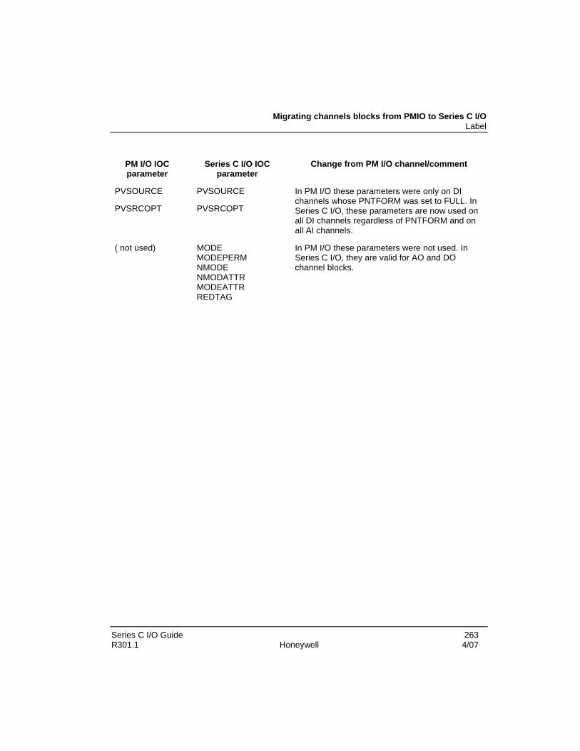
Migrating channels blocks from PMIO to Series C I/O Label
Series C I/O Guide 263 R301.1 Honeywell 4/07
PM I/O IOC parameter
Series C I/O IOC parameter
Change from PM I/O channel/comment
PVSOURCE PVSOURCE
PVSRCOPT PVSRCOPT
In PM I/O these parameters were only on DI channels whose PNTFORM was set to FULL. In Series C I/O, these parameters are now used on all DI channels regardless of PNTFORM and on all AI channels.
( not used) MODE MODEPERM NMODE NMODATTR MODEATTR REDTAG
In PM I/O these parameters were not used. In Series C I/O, they are valid for AO and DO channel blocks.


Series C I/O Guide 265 R301.1 Honeywell 4/07
Series C I/O Troubleshooting
Initial checks This section offers checks that you can make to help isolate a problem. The checks are arranged in no particular order.
Checking Control Builder error code reference An indication of a problem may be in the form of an error dialog that includes an error message and possibly an error code in Control Builder.
The syntax for a typical Control Builder error message is as follows:
Connection to device is not open EPKS_E_CL_NOCONN(6L.101.3326)
In this syntax, the error code is the last four digits in the message or 3326.
Please refer to the Control Builder Error Codes Reference book for applicable error code information.
Checking front panel display and LEDs Check the Series C module character display and Series C IOTA light emitting diodes (LEDs) indications.
Upgrading Firmware in Series C I/O components Upgrading firmware in Series C I/O components in the Control Hardware and I/O Module Firmware Guide.
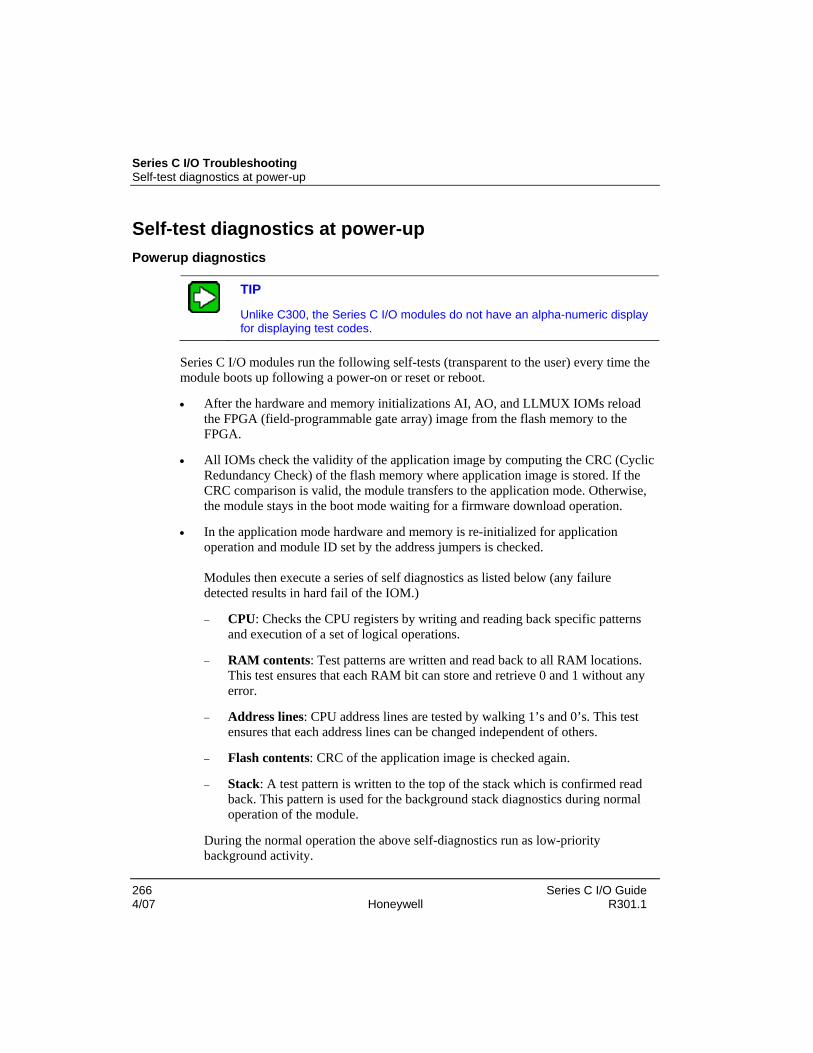
Series C I/O Troubleshooting Self-test diagnostics at power-up
266 Series C I/O Guide 4/07 Honeywell R301.1
Self-test diagnostics at power-up Powerup diagnostics
TIP
Unlike C300, the Series C I/O modules do not have an alpha-numeric display for displaying test codes.
Series C I/O modules run the following self-tests (transparent to the user) every time the module boots up following a power-on or reset or reboot.
• After the hardware and memory initializations AI, AO, and LLMUX IOMs reload the FPGA (field-programmable gate array) image from the flash memory to the FPGA.
• All IOMs check the validity of the application image by computing the CRC (Cyclic Redundancy Check) of the flash memory where application image is stored. If the CRC comparison is valid, the module transfers to the application mode. Otherwise, the module stays in the boot mode waiting for a firmware download operation.
• In the application mode hardware and memory is re-initialized for application operation and module ID set by the address jumpers is checked. Modules then execute a series of self diagnostics as listed below (any failure detected results in hard fail of the IOM.)
− CPU: Checks the CPU registers by writing and reading back specific patterns and execution of a set of logical operations.
− RAM contents: Test patterns are written and read back to all RAM locations. This test ensures that each RAM bit can store and retrieve 0 and 1 without any error.
− Address lines: CPU address lines are tested by walking 1’s and 0’s. This test ensures that each address lines can be changed independent of others.
− Flash contents: CRC of the application image is checked again.
− Stack: A test pattern is written to the top of the stack which is confirmed read back. This pattern is used for the background stack diagnostics during normal operation of the module.
During the normal operation the above self-diagnostics run as low-priority background activity.

Self-test diagnostics at power-up Powerup diagnostics
Series C I/O Guide 267 R301.1 Honeywell 4/07
• Application specific database objects are created and task scheduler is initialized. Watchdog circuitry and IOL are enabled and normal operation of the module begins.
• There are application specific diagnostic routines that run during the normal operation which normally runs at a higher rate and priority. Examples of application specific diagnostics are:
− Checking the integrity of calibration data
− Redundancy diagnostics in redundantly configured modules
− Reference voltage tests in analog modules
− Open wire detection
− Short circuit detection in DO modules
Series C I/O Troubleshooting Communication problems
268 Series C I/O Guide 4/07 Honeywell R301.1
Communication problems IOLINK - loss of communications
IOMs can experience a loss of communication with the IOLINK function block for several reasons. The two most common reasons are:
• the C300 losing power, or
• a fault in the IOLINK cable
Whenever an IOM can no longer communicate with a C300, the channels contained within the IOM use the following:
• FAULT parameters
− FAULTOPT, and
− FAULTVALUE
• and a separate IOM internal fail-safe timeout to ensure that the channel is in the appropriate fail-safe setting.
IOLINK - re-establishing communications
Once communication between a C300 and an IOM is re-established, the C300 determines if the databases between the C300 and IOM are identical. If they are different and the IOM’s DBVALID flag is true, then the C300 uploads the configuration from the IOM.
If the IOM's DBVALID is false and if C300 has a copy of last valid IOM configuration, then the C300 downloads the configuration to the IOM. This warm restore mechanism replaces the warm start mechanism in PM IOPs.

Series C I/O Guide 269 R301.1 Honeywell 4/07
Series C I/O Maintenance
Series C recommended spares The following table provides replacement parts, or parts that you may want to keep on hand for backup.
Table 70 Recommended spare parts
Part name Part number Description
ANALOG INPUT
Series C AI IOM CC- PAIH01 or CU-PAIH01
Series C Analog Input Module
IOTA
Non-Redundant. IOTA
CC- TAIX01 51308363-175
CU-TAIX01 51308363-125
Analog Input, non-redundant, coated
Analog Input, non-redundant, non-coated
Redundant. IOTA CC- TAIX11 51308365-175
CU-TAIX11 51308365-125
Analog Input, redundant, coated
Analog Input, redundant, non-coated
Terminal plug-in assembly
16-terminal block plug-in assembly
51506273-216 2 per IOTA
4-terminal block plug-in assembly
51506269-204 1 per IOTA
Fuses
Description Part number Quantity Reference designator
Function
Fuse 750 mA, 5x20, fast acting
51190582-175 1 per non-red. IOTA
F1 The fuse covers the IOM and the power feeds to the field wiring. A blown fuse interrupts power to

Series C I/O Maintenance Series C recommended spares
270 Series C I/O Guide 4/07 Honeywell R301.1
Part name Part number Description these.
2 per red. IOTA
F1 F2
F1 covers upper IOM F2 covers lower IOM
If one fuse is blown power is interrupted to the IOM, but field wiring continues to receive power from other fuse.
ANALOG OUPUT
Series C AO IOM CC- PAOH01 or CU-PAOH01
Series C Analog Output Module
IOTA
AO Non-Redundant. IOTA
CC-TAOX01 51308351-175
CU-TAOX01 51308351-125
Analog Output, non-redundant, coated
Analog Output, non-redundant, non-coated
AO Redundant. IOTA
CC- TAOX11 51308353-175
CU-TAOX11 51308353-125
Analog Output, redundant, coated
Analog Output, redundant, non-coated
Terminal plug-in assembly
16-pin terminal plug-in assembly
51506273-216 2 per non-redundant IOTA 2 per redundant IOTA
Fuses
Description Part number Quantity Reference designator
Function
1 per non-red. IOTA F2 Fuse 1A Fast acting 5x20mm
51190582-210
1 per red. IOTA F3
Standby Manual connector fuse
1 per non-red. IOTA F1 Fuse 2A Fast acting 5x20mm
51190582-220
2 per red. IOTA F1, F2
Module fuse

Series C recommended spares IOLINK - re-establishing communications
Series C I/O Guide 271 R301.1 Honeywell 4/07
Part name Part number Description
ANALOG INPUT LOW LEVEL
Series C AI Low Level IOM
CC-PAIM01 or CU- PAIM01
Series C Low Level Module
IOTA
AI Low Level IOTA
CC--TAIM01 51305959-175
CU-TAIM01 51305959-125
AI Low Level, non-redundant, coated
AI Low Level, non-redundant, non-coated
Connector block assembly
Connector Block Assembly, 6 Position
51195775-100 4 per IOTA
Fuse
Description Part number Quantity Reference designator
Function
F3 Power to FTA 1 only
F4 Power to FTA 2 only
F5 Power to FTA 3 only
FUSE, 0.25 Amp, Quick Blo, 5x20mm
51190582-125 4 per IOTA
F6 Power to FTA 4 only
F1 Power to module electronics
FUSE, 1 Amp, 125V, Quick Blo, 5x20mm
51190582-210 2 per IOTA
F2 Switched power to all FTAs
DIGITAL INPUT 24V
Series C DI-24 IOM
CC- PDIL01 or CU-PDIL01
Series C 24V Digital Input Module
IOTA
DI-24V Non-Redundant. IOTA
CC- TDIL0 51308371-175
24V Digital Input, non-redundant, coated

Series C I/O Maintenance Series C recommended spares
272 Series C I/O Guide 4/07 Honeywell R301.1
Part name Part number Description
CU-TDIL01 51308371-125
24V Digital Input, non-redundant, non-coated
DI-24V Redundant. IOTA
CC- TDIL1 51308373-175
CU-TDIL11 51308373-125
24V Digital Input, redundant, coated
24V Digital Input, redundant, non-coated
Terminal plug-in assembly
16-terminal plug-in assembly
51506273-216 2 per non-redundant IOTA 2 per redundant IOTA
4-terminal plug-in assembly
51506269-204 1 per non-redundant IOTA 1 per redundant IOTA
Fuses
Description Part number Quantity Reference designator
Function
F1
Fuse for field power if system power is connected via TB3, in series with F3
F2 Top IOM kernel
3 per non-red. IOTA
F3 Fuse for field power if external power is connected via TB3
F1 Top IOM kernel
F2 Fuse for field power if system power is connected via TB3, in series with F4
F3 Bottom IOM kernel
Fuse 0.5A Fast acting 5x20mm
51190582-150
4 per red. IOTA
F4 Fuse for field power if external power is connected via TB3
DIGITAL OUPTUT 24V

Series C recommended spares IOLINK - re-establishing communications
Series C I/O Guide 273 R301.1 Honeywell 4/07
Part name Part number Description
Series C DO IOM CC--PDOB01 or CU-PDOB01
Series C Digital Output Module
IOTA
24V DO Non-Redundant IOTA
CC--TDOB01 51308371-175
CU-TDOB01 51308371-125
24V Digital Output, bussed, non-redundant
24V Digital Output, bussed, non-redundant
24V DO Redundant IOTA
CC--TDOB11 51308373-175
CU-TDOB11 51308373-125
24V Digital Output, bussed, redundant, coated
24V Digital Output, bussed, redundant, non-coated
Terminal plug-in assemblies
16-terminal plug-in assembly
51506273-216 2 per non-redundant IOTA 2 per redundant IOTA
4-terminal plug-in assembly
51506269-204 1 per non-redundant IOTA 1 per redundant IOTA
Fuses
Description Part number Quantity Reference designator
Function
1 per non-red. IOTA F1 Fuse 10A Fast acting 5x20mm
51190582-310
1 per red. IOTA F1
Fuse for field power if system power is connected via TB3
1 per non-red. IOTA F2 Fuse for IOM kernel Fuse 0.5A Fast acting 5x20mm
51190582-150
2 per red. IOTA F2, F3
Top IOM kernel Bottom IOM kernel
DIGITAL INPUT – HIGH VOLTAGE
Series C DI-24 IOM
CC- DIHV01 or CU-DIHV01
Series C Digital Input High Voltage I/O Module
IOTA
120VAC DI Non-Redundant.
CC-TDI110 51308394-175
120VAC Digital Input, non-redundant, coated

Series C I/O Maintenance Series C recommended spares
274 Series C I/O Guide 4/07 Honeywell R301.1
Part name Part number Description IOTA CU-TDI110
51308394-125 120VAC Digital Input, non-redundant, non-coated
120VAC DI Redundant. IOTA
CC-TDI120 51308396-175
CU-TDI120 51308396-125
120VAC Digital Input, redundant, coated
120VAC Digital Input, redundant, non-coated
240VAC DI Non Redundant IOTA
CC-TDI220 51308394-275
CU-TDI220 51308394-225
240VAC Digital Input, non-redundant, coated
240VAC Digital Input, non-redundant, non-coated, Input Output Terminal Assembly
240VAC DI Redundant IOTA
CC-TDI230 51308396-275
CU-TDI230 51308396-225
240VAC Digital Input, non-redundant, coated
240VAC Digital Input, redundant, non-coated, Input Output Terminal Assembly
Terminal plug-in assembly
16-terminal plug-in assembly
51506273-216 2 per non-redundant IOTA 2 per redundant IOTA
Fuse
Description Part number Quantity Reference designator
Function
1 per non-red. IOTA F1 +24vdc power for IOM
F1 +24vdc power for top IOM
Fuse 0.5A Fast acting 5x20mm
51190582-150
2 per red. IOTA
F2 +24vdc power for bottom IOM
DIGITAL OUTPUT HIGH VOLTAGE RELAY
Series C DO IOM CC- PDOB01 or CU-PDOB01
Series C Digital Output Module
DO Relay Extender
51308380 Series C Digital Output Relay Extender

Series C recommended spares IOLINK - re-establishing communications
Series C I/O Guide 275 R301.1 Honeywell 4/07
Part name Part number Description
DO-HV Relay Non-Redundant. IOTA
CC- TDOR01 51308376-175
CU-TDOR01 51308376-125
Digital Output High Voltage, relay, non-redundant, coated
Digital Output High Voltage, relay, non-redundant, non-coated
DO-HV Relay Redundant. IOTA
CC- TDOR11 51308378-175
CU-TDOR11 51308378-125
Digital Output High Voltage, relay, redundant, coated
Digital Output High Voltage, relay, redundant, non-coated
Miscellaneous
Jumper Link 30731551-001 32 per DO Relay Extender
Slim Power Relay 24VDC (Tyco)
51506348-100 32 per DO Relay Extender
16-terminal plug-in assembly
51506273-216 4 per DO Relay Extender
Fuses
Description Part number Quantity Reference designator
Function
1 per non-red. IOTA F2 Fuse 1A Fast acting 5x20mm
51190582-210
1 per red. IOTA F1
When this fuse blows, the 24V to DO IOM (Application Board) stops. It covers energizing current for 32 relay coils.
1 per non-red. IOTA F1 Covers current to kernel board.
F2 Top IOM kernel
Fuse 0.5A Fast acting 5x20mm
51190582-150
2 per red. IOTA
F3 Bottom IOM kernel
GENERAL
Fuseholder 51506443-100

Series C I/O Maintenance IOM removal and installation under power
276 Series C I/O Guide 4/07 Honeywell R301.1
IOM removal and installation under power The IOM has been designed to permit removal and installation under power (RIUP) without damaging the module or interrupting IOTA communications. Notice should be taken on how this may impact the active process.
CAUTION
We recommend that you proceed with extreme caution whenever replacing any component in a control system. Be sure the system is offline or in a safe operating mode.
Component replacements may also require corresponding changes in the control strategy configuration through Control Builder, as well as downloading appropriate data to the replaced component.
Refer to Replacing an I/O module for IOM replacement and cautionary information.

Series C I/O Guide 277 R301.1 Honeywell 4/07
Series C I/O Alarms and Failures
Reviewing IOM alarms generated by the C300 IOM alarms
The IOM block reports diagnostic alarms in the event of an IOM hardware failure or a change in the IOM redundancy state. The IOM alarms that the C300 presents are listed in the notification table below.
Table 71 IOM alarms displayed by the C300 controller
Notification type Auxiliary descriptor text
Diagnostic alarm • Communication error
• Configuration mismatch
• No response
System info event • IOM power on
• IOM not synchronized
• IOM synchronized
• IOM switchover
• IOM swap control HART alarms/events
In addition to the existing PMIO functionality, the following are added to Series C HART IOMs.
Field device status notifications
Field device status notifications has one more extra byte called “extended device status notifications”. This byte is supported only by HART 6.0 devices.

Series C I/O Alarms and Failures Reviewing IOM alarms generated by the C300
278 Series C I/O Guide 4/07 Honeywell R301.1
Currently, only the following two bits of this byte are defined.
Extended device condition/bit Type Definition
Maintenance required / Bit 0 Alarm Device requires maintenance.
Device variable alert / Bit 1 Alarm Any device variable is in alarm or warning state.
HALARMENABLE
A new parameter – HALARMENABLE – is added to HART configuration tab in the channel block. This parameter is by default enabled and can be changed from Monitoring side, irrespective of the channel point execution state of the IOM module state.
When HALARMENABLE is disabled, all the existing HART events / alarms from that channel block are disabled and further generation of the HART alarms / events are terminated.
This parameter affects only the HART alarm / event behavior. The LED update of the device status in the HART device status tab happens regardless of the state of HALARMENABLE.

Series C I/O Alarms and Failures Reviewing IOM soft failures
Series C I/O Guide 279 R301.1 Honeywell 4/07
Reviewing IOM soft failures IOM soft failures
The IOM reports device soft failures to Experion Server and also located on the Control Builder configuration forms under the Soft Failures tab.
The table below lists all IOM soft failures and identifies those that appear within Experion. Since Series C I/O is not slated for use with TPS, soft failures related to TPS are not be provided by Series C I/O modules.
The SOFTFAIL1A, SOFTFAIL1B, SOFTFAIL2A and SOFTFAIL2B parameters are used to view an IOM’s soft failures. For a list of channels in failure, use the CHNLWFAILA and CHNLWFAILB parameters.
00 Null soft failure – not failure
Diagnostic check: Null soft failure – no failure
Cause: Null soft failure – no failure
Solution: No action 01 STCOVRUN
Sample time clock overrun
Diagnostic check: Investigate a possible I/O Link problem
Cause: Sample time clock overrun
Solution: Investigate a possible I/O Link problem or excessive IOL activity. Check C300, IOL cables, IOMs and IOL budgets. Call TAC if the alarm persists or repeatedly occurs.
02 REQOFLOW
IOP task request overflow - excessive IOL activity
Diagnostic check: Check IOL activity
Cause: IOP task request overflow - excessive IOL activity
Solution: Call TAC for assistance.

Series C I/O Alarms and Failures Reviewing IOM soft failures
280 Series C I/O Guide 4/07 Honeywell R301.1
03 BADRESUM
IOP EXEC resumed a non-waiting task
Diagnostic check: None
Cause: IOP EXEC resumed a non-waiting task - software bug indicated
Solution: Call TAC for assistance. 04 DIAGTMOT
Diagnostics not run in at least 5 secs. – indicates a processing overload
Diagnostic check: Investigate control point mix/strategy for an excessive load.
Cause: Diagnostics not run in at least 5 secs. - indicates a processing overload.
Solution: Investigate control point mix/strategy for an excessive load. Otherwise, a possible I/O Link problem exists. Check the C300, the I/O Link cable, and the IOM cards.
05 DIAGOFLO
Entire diagnostic cycle overran the allocated time
Diagnostic check: None - diagnostic cycle overrun.
Cause: Entire diagnostic cycle overran the allocated time in which diagnostics have to run to completion.
Solution: Investigate control point mix/strategy for an excessive load. Otherwise, a possible I/O Link problem exists. Check the C300, the I/O Link cable, and the IOM cards.

Series C I/O Alarms and Failures Reviewing IOM soft failures
Series C I/O Guide 281 R301.1 Honeywell 4/07
06 FTAMISSG LLMUX, power adaptor, or DO Relay IOM config. is missing relay adapter board
Diagnostic check: Check for missing items defined below.
Cause: If LLMUX, power adapter missing or if DO Relay IOM configuration is missing relay adapter board.
Solution: Install the FTA or relay adapter. If an FTA is present, replace the FTA or check the FTA cable. (Note: For the LLMux, this code refers to the Power Adapter assembly. RTD and TC FTAs are diagnosed by error Codes 50 and 51.)
07 EECKSMER
EEPROM checksum error - IOM probably not calibrated
Diagnostic check: EEPROM checksum error - IOM probably not calibrated
Cause: EEPROM (used to hold calibration information in Analog Input and Analog Output IOPs) checksum failure. It usually means an Analog Output IOM is not calibrated properly.
Solution: Calibrate the Analog Input or Analog Output IOM (refer to the "IOM Calibration Procedures" section for the procedure). If the error persists, replace the IOM.
08 EECNTERR
EEPROM counter error-too many writes
Diagnostic check: Check EEPROM counter.
Cause: EEPROM counter error. The number of writes to EEPROM has exceeded the safe number (10,000). This could also indicate the IOM has not been calibrated because a virgin EEPROM will fail this test.
Solution: Calibrate the Analog Input or Analog Output IOM (refer to the "IOM Calibration Procedures" section for the procedure). If the error persists, replace the IOM.

Series C I/O Alarms and Failures Reviewing IOM soft failures
282 Series C I/O Guide 4/07 Honeywell R301.1
09 EEFLAGER EEPROM flag error - incomplete EEPROM write resulting in uncalibrated IOM
Diagnostic check: Check EEPROM.
Cause: EEPROM flag error - incomplete EEPROM write resulting in uncalibrated IOM.
Solution: Calibrate the Analog Input or Analog Output IOM (refer to the "IOM Calibration Procedures" section for the procedure). If the error persists, replace the IOM.
19 SCNORUN
Input module scan overrun , excessive IOL activity to this IOP
Diagnostic check: Input overran its input scan.
Cause: Input module scan overrun, excessive IOL activity to this IOP. Inputs have been lost.
Solution: Check for a "chattering" DI point. Another possible cause would be intermittently bad I/O link hardware.
23 OUTPUTFL
Failure in output circuit / field wiring detected by AO or DO.
Diagnostic check: Check field wiring and the fuses on the IOTA.
Cause: Failure in output circuit / field wiring detected by AO or DO.
Solution: Check field wiring and the fuses on the IOTA. If it is good, try replacing the IOTA and/or the appropriate IOM card.
24 STCKLIM
IOM firmware stack usage is dangerously close to its limit.
Diagnostic check: Stack reaching limit.
Cause: IOM firmware stack usage is dangerously close to its limit.
Solution: Reduce activity on this IOM – inactivate control strategies. Call TAC for assistance.

Series C I/O Alarms and Failures Reviewing IOM soft failures
Series C I/O Guide 283 R301.1 Honeywell 4/07
26 DIAGCTFL
IOM diagnostic circuit failure
Diagnostic check: IOM diagnostic circuit failure.
Cause: IOM diagnostic circuit failure.
Solution: Check for chattering inputs. Reset the IOM. If reset does not clear the error, replace the appropriate IOM.
31 FTAMSMCH
LLMUX FTA type mismatch with channel configuration.
Diagnostic check: Check channel block configuration.
Cause: LLMUX FTA type mismatch with channel configuration.
Solution: Reconfigure the channel block or replace the FTA. 32 VZERO
Zero reference voltage out of range in AI and AO IOMs
Diagnostic check: Zero reference failure.
Cause: Zero reference voltage out of range in AI and AO IOMs
Solution: Replace the IOM. 36 FTA1FAIL
LLMUX :FTA 1 has a soft failure
Diagnostic check: Check LLMUX FTA 1
Cause: LLMUX FTA 1 has a soft failure.
Solution: Check LLMUX FTA 1

Series C I/O Alarms and Failures Reviewing IOM soft failures
284 Series C I/O Guide 4/07 Honeywell R301.1
37 FTA2FAIL LLMUX FTA 2 has a soft failure
Diagnostic check: Check LLMUX FTA 2
Cause: LLMUX FTA 2 has a soft failure.
Solution: Check LLMUX FTA 2 39 BADCALRF
Internal calibration test voltages out of range.
Diagnostic check: None - Internal calibration test voltages out of range.
Cause: Internal calibration test voltages out of range.
Solution: Replace AI or AO IOM. 41 VREFFAIL
Reference voltage out of range
Diagnostic check: Check reference voltage
Cause: Internal 5V reference out of range in AI or internal AA55 reference test failed in the case of DI.
Solution: Replace the AI or DI IOM. 42 ADOUTUDF
Analog to digital conversion on this Analog Input channel is out of range.
Diagnostic check: Check input wiring.
Cause: Analog to digital conversion on this Analog Input channel is out of range.
Solution: Check the input wiring at the IOTA; possible open contact. Otherwise, replace the IOM.

Series C I/O Alarms and Failures Reviewing IOM soft failures
Series C I/O Guide 285 R301.1 Honeywell 4/07
43 ADOUTCAL AI or AO IOM is out of calibration.
Diagnostic check: Check AI or AO IOM calibration
Cause: AI or AO IOM is out of calibration.
Solution: Calibrate or replace the IOM (refer to the "IOP Calibration Procedures" section).
50 F1COM_FL
LLMUX FTA 1 communication failure.
Diagnostic check: LLMUX FTA 1 communication failure.
Cause: LLMUX FTA 1 communication failure.
Solution: Check the connection from the Power Adapter to FTA 1. If the FTA is missing, install the FTA. If the FTA is present, replace the FTA.
51 F2COM_FL
LLMUX FTA 2 communication failure.
Diagnostic check: LLMUX FTA 2 communication failure 2.
Cause: LLMUX FTA 2 communication failure.
Solution: Check the connection from the Power Adapter to FTA 2. If the FTA is missing, install the FTA. If the FTA is present, replace the FTA.

Series C I/O Alarms and Failures Reviewing IOM soft failures
286 Series C I/O Guide 4/07 Honeywell R301.1
52 F1_IDERR LLMUX FTA 1 identification failure.
Diagnostic check: LLMUX FTA 1 identification failure.
Cause: LLMUX FTA 1 identification failure.
Solution: Verify/correct the FTA pinning. 53 F2_IDERR
LLMUX FTA 2 identification failure.
Diagnostic check: LLMUX FTA 2 identification failure.
Cause: FTA 2 identification failure
Solution: Verify/correct the FTA pinning. 54 F1VREFFL
LLMUX FTA 1 reference voltage failure
Diagnostic check: LLMUX FTA 1 reference voltage failure
Cause: LLMUX FTA 1 reference voltage failure
Solution: Replace the FTA. 55 F2VREFFL
LLMUX FTA 2 reference voltage failure
Diagnostic check: LLMUX FTA 2 reference voltage failure
Cause: LLMUX FTA 2 reference voltage failure
Solution: Replace the FTA.

Series C I/O Alarms and Failures Reviewing IOM soft failures
Series C I/O Guide 287 R301.1 Honeywell 4/07
56 F1CAL_FL LLMUX FTA 1 calibration failure.
Diagnostic check: LLMUX FTA 1 calibration failure.
Cause: LLMUX FTA 1 calibration failure.
Solution: Recalibrate the FTA. 57 F2CAL_FL
LLMUX FTA 2 calibration failure.
Diagnostic check: LLMUX FTA 2 calibration failure.
Cause: LLMUX FTA 2 calibration failure.
Solution: Recalibrate the FTA. 61 REDNDIAG
Redundancy hardware diagnostic failure.
Diagnostic check: Redundancy hardware diagnostic failure.
Cause: Redundancy hardware diagnostic failure.
Solution: Replace the IOMs one at a time following database synchronization.
161 HMODEM1
HART hardware error detected against DUART channel 1 or modem 1.
Diagnostic check: None - HART hardware error detected
Cause: HART hardware error detected against DUART channel 1 or modem 1.
Solution: Replace the IOM.

Series C I/O Alarms and Failures Reviewing IOM soft failures
288 Series C I/O Guide 4/07 Honeywell R301.1
162 HMODEM2 HART hardware error detected against DUART channel 2 or modem 2.
Diagnostic check: None - HART hardware error detected
Cause: HART hardware error detected against DUART channel 2 or modem 2.
Solution: Replace the IOM. 163 HMODEM3
HART hardware error detected against DUART channel 3 or modem 3.
Diagnostic check: None - HART hardware error detected
Cause: HART hardware error detected against DUART channel 3 or modem 3.
Solution: Replace the IOM. 164 HMODEM4
HART hardware error detected against DUART channel 4 or modem 4.
Diagnostic check: None - HART hardware error detected
Cause: HART hardware error detected against DUART channel 4 or modem 4.
Solution: Replace the IOM. 167 FTA3FAIL
LLMUX: FTA 3 has a Soft failure.
Diagnostic check: Check FTA 3.
Cause: LLMUX: FTA 3 has a Soft failure.
Solution: Check FTA 3. This soft failure is introduced in Series C.

Series C I/O Alarms and Failures Reviewing IOM soft failures
Series C I/O Guide 289 R301.1 Honeywell 4/07
168 FTA4FAIL LLMUX: FTA 4 has a Soft failure.
Diagnostic check: Check FTA 4.
Cause: LLMUX: FTA 4 has a Soft failure.
Solution: Check FTA 4. This soft failure is introduced in Series C. 171 F3COMFL
LLMUX FTA 3 communication failure.
Diagnostic check: LLMUX FTA 3 communication failure.
Cause: LLMUX FTA 3 communication failure.
Solution: Check the connection from the Power Adapter to FTA 1. If the FTA is missing, install the FTA. If the FTA is present, replace the FTA. This soft failure is introduced in Series C.
172 F4COMFL
LLMUX FTA 4 communication failure.
Diagnostic check: LLMUX FTA 4 communication failure.
Cause: LLMUX FTA 4 communication failure.
Solution: Check the connection from the Power Adapter to FTA 2. If the FTA is missing, install the FTA. If the FTA is present, replace the FTA. This soft failure is introduced in Series C.
173 F3IDERR
LLMUX FTA 3 identification failure.
Diagnostic check: Verify/correct the FTA pinning.
Cause: LLMUX FTA 3 identification failure.
Solution: Verify/correct the FTA pinning. This soft failure is introduced in Series C.

Series C I/O Alarms and Failures Reviewing IOM soft failures
290 Series C I/O Guide 4/07 Honeywell R301.1
174 F4IDERR LLMUX FTA 4 identification failure.
Diagnostic check: Verify/correct the FTA pinning.
Cause: LLMUX FTA 4 identification failure.
Solution: Verify/correct the FTA pinning. This soft failure is introduced in Series C.
175 F3VREFFL
LLMUX FTA 3 reference voltage failure.
Diagnostic check: None
Cause: LLMUX FTA 3 reference voltage failure.
Solution: Replace the FTA. This soft failure is introduced in Series C. 176 F4VREFFL
LLMUX FTA 4 reference voltage failure.
Diagnostic check: None
Cause: LLMUX FTA 4reference voltage failure.
Solution: Replace the FTA. This soft failure is introduced in Series C. 177 F3CALFL
LLMUX FTA 3 calibration failure.
Diagnostic check: Check FTA calibration
Cause: LLMUX FTA 3 calibration failure.
Solution: Recalibrate the FTA. This soft failure is introduced in Series C.

Series C I/O Alarms and Failures Reviewing IOM soft failures
Series C I/O Guide 291 R301.1 Honeywell 4/07
178 F4CALFL LLMUX FTA 4 calibration failure.
Diagnostic check: Check FTA calibration
Cause: LLMUX FTA 4 calibration failure.
Solution: Recalibrate the FTA. This soft failure is introduced in Series C. 179 OPENWIRE
Open wire / sensor detected.
Diagnostic check: Check the field wiring and IOTA connections.
Cause: Open wire / sensor detected.
Solution: Check the field wiring and IOTA connections. 180 DOVRCRNT
DO channel detected a short circuit or over current situation.
Diagnostic check: Check the field wiring and IOTA connections.
Cause: DO channel detected a short circuit or over current situation.
Solution: Check the field wiring and IOTA connections. 181 FTAPOWFL
LLMUX IOM is not able to power the FTAs.
Diagnostic check: LLMUX IOM is not able to power the FTAs.
Cause: LLMUX IOM is not able to power the FTAs.
Solution: Replace the IOM. This soft failure is introduced in Series C.

Series C I/O Alarms and Failures Reviewing IOM soft failures
292 Series C I/O Guide 4/07 Honeywell R301.1
182 DPADIAFAIL IOL Address Diag Failure
Diagnostic check: IOL address diagnostic failure
Cause: IOL address diagnostic failure
Solution: Check IOM number at device index switch. Ensure correct assignment. If not correct, reset to correct device index number. Reset IOM.
183 RDBKRGDIAGFL
Readback Register Diagnostic Failure
Diagnostic check: Readback register diadnostic failure
Cause: Readback register diadnostic failure
Solution: Internal hardware problem. Replace the IOM. 184 WDTDIAGFAIL
Watch Dog Timer Diagnostic Failure
Diagnostic check: Watch Dog Timer diagnostic failure
Cause: Watch Dog Timer diagnostic failure
Solution: Replace the module. 185 RLYEXTBDMSSNG
Relay Extension Board Missing
Diagnostic check: Relay Extension Board missing
Cause: Relay Extension Board missing
Solution: Ensure Relay Board is properly installed.

Series C I/O Alarms and Failures Reviewing IOM hard failures
Series C I/O Guide 293 R301.1 Honeywell 4/07
Reviewing IOM hard failures IOM hard failures
IOM reports device hard failures on the Configuration Form’s Maintenance tab for the IOMLHFSTA / IOMLHFSTB parameters.
Figure 67 Location of hard failure message
To review the FAULTED state of AO and DO failures see, FAULTED state and IOM hard failure
The following codes can appear for the IOMLHFSTA and IOMLHFSTB parameters.
Table 72 IOM hard failures Code Name Cause/description AI AO DI DO LLMUX
00 UNKNOWN Unknown failure. X X X X X
01 POWERDOWN IOM was powered down or a loss of 24v power to the IOM was detected
X X X X X
02 INVPRGEXEC Invalid program execution X X X X X
04 RAMCNTERR RAM contents diagnostics failed
X X X X X
05 RAMADRERR RAM address diagnostics failed
X X X X X
06 DPAERROR IOM was changed while the IOM is powered
X X X X X
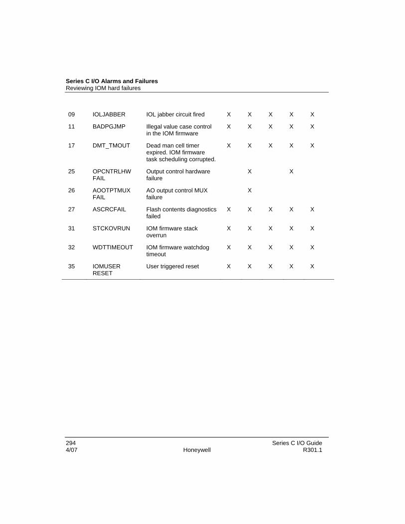
Series C I/O Alarms and Failures Reviewing IOM hard failures
294 Series C I/O Guide 4/07 Honeywell R301.1
09 IOLJABBER IOL jabber circuit fired X X X X X
11 BADPGJMP Illegal value case control in the IOM firmware
X X X X X
17 DMT_TMOUT Dead man cell timer expired. IOM firmware task scheduling corrupted.
X X X X X
25 OPCNTRLHW FAIL
Output control hardware failure
X X
26 AOOTPTMUX FAIL
AO output control MUX failure
X
27 ASCRCFAIL Flash contents diagnostics failed
X X X X X
31 STCKOVRUN IOM firmware stack overrun
X X X X X
32 WDTTIMEOUT IOM firmware watchdog timeout
X X X X X
35 IOMUSER RESET
User triggered reset X X X X X

Series C I/O Alarms and Failures Getting further assistance
Series C I/O Guide 295 R301.1 Honeywell 4/07
Getting further assistance Other troubleshooting sources
The following table lists other documents and sections that contain troubleshooting information for other Experion subsystems.
All of these documents are available from Knowledge Builder. Some documents are also supplied as part of Station Help. For documents that can be accessed directly from this page, click on the link, otherwise look for the document within Knowledge Builder.
Document/Section Comments
Experion R300 > Reference There is a separate interface reference for each type of controller other than the Process Controller; for example, the ASEA Interface Reference.
Most of these references contain an interface-specific troubleshooting section.
Experion R300 > Reference > TPS Integration Guide > Troubleshooting
Troubleshooting an integrated system that uses Experion "TPS Integration" option.
Experion R300 > Reference > Control Builder Error Codes Reference
Describes error codes generated from within Control Builder.
Experion R300 > Troubleshooting and Maintenance > Control Hardware Troubleshooting and Maintenance Guide
The main repository for troubleshooting, maintenance and repair of Process Controllers.
Experion R300 > Configuration > DeviceNet Interface Implementation Guide > Troubleshooting DeviceNet Status Failures
Describes error codes generated from DeviceNet Interface Board.
Experion R300 > Configuration > Fault Tolerant Ethernet Bridge User’s Guide > Service > Troubleshooting
Troubleshooting FTE bridges.
Experion R300 > Installation and Upgrades > Fault Tolerant Ethernet Installation and Service Guide > Troubleshooting FTE Nodes
Troubleshooting FTE nodes.
Experion R300 > Reference > Honeywell TDC 3000 Data Hiway Interface Reference > TDC error codes and Troubleshooting
Troubleshooting TDC 3000 Hiway problems.
Experion R300 > Configuration > Qualification Troubleshooting QVCS.

Series C I/O Alarms and Failures Getting further assistance
296 Series C I/O Guide 4/07 Honeywell R301.1
Document/Section Comments and Version Control System User Guide > QVCS Troubleshooting
Experion R300 > Configuration > SafeView User's Guide > Appendix D - SafeView Error Messages
Describes the meaning of SafeView configuration errors.
Experion R300 > Reference > Server Scripting Reference > Server scripting error messages
Describes the meaning of error messages in the server log specific to server scripting.
Experion R300 > Configuration > System Management Configuration Guide > Troubleshooting System Management
Describes the meaning of System Management Configuration errors.
Experion R300 > Configuration > System Management Configuration Guide > System Event Server > Troubleshooting SES configuration
Describes the meaning of SES Configuration errors.
Experion R300 > Configuration > System Management Configuration Guide > System Performance Server > Troubleshooting SPS configuration
Describes the meaning of SPS Configuration errors.
Experion R300 > Planning and Design > Planning, Installation, and Service for WS360
Troubleshooting workstation nodes used in Experion and TPN.
Guidelines for requesting support
If you cannot resolve a problem by using this guide, you can request support from your Honeywell Solutions Support Center. When requesting support, please supply as many relevant details about the problem by referring to Gathering information for reporting problems to Honeywell to obtain the problem-related information.

Series C I/O Guide 297 R301.1 Honeywell 4/07