Embed Size (px)
Citation preview

THE FINEST RADIO CONTROL MODELS
R
※製品改良のため、予告なく仕様を変更する場合があります。 SPECIFICATIONS ARE SUBJECT TO CHANGE WITHOUT NOTICE.
●キットの他にそろえる物 REQUIRED FOR OPERATION●組立て前の注意 BEFORE YOU BEGIN●本体の組立て ASSEMBLY●調整・飛行練習・メンテナンス SETTINGS ¥ FLIGHT LESSONS ¥ MAINTENANCE●パーツリスト PARTS LIST●分解図 EXPLODED VIEW●取扱いの注意 OPERATING YOUR MODEL SAFELY●スペアパーツ・オプションパーツリスト SPARE & OPTIONAL PARTS
23 ~ 4
5 ~ 1415 ~ 22
2324 ~ 26
2728 ~ 29
目 次 INDEX
EP コンセプト SR
INSTRUCTION MANUAL
※ご使用前にこの説明書を良くお読みになり十分に理解してください。Before commencing assembly, please read these instructions thoroughly.
組立/取扱説明書
RADIO CONTROLLED ELECTRIC POWERED HELICOPTER SERIES
EP CONCEPT TYPE SKY RUNNER
フレーム編
FRAME SECTION
Ni-Cd
・不要になったニカドバッテリーは、貴重な資源を守るために廃棄しないでリサイクル協力店へお持ちください。
・The product you have purchased is powered by a rechargeable battery. The battery is recyclable. At the end of its useful life, under various national / state and local laws, it may be illegal to dispose of this battery into the municipal waste stream. Check with your local solid waste officials for details in your area for recycling options or proper disposal.
安全のための注意事項 SAFETY PRECAUTIONSThis radio control model is not a toy.この無線操縦模型は玩具ではありません!
●この商品は高い性能を発揮するように設計されています。 組立てに不慣れな方は、模型を良く知っている人にアド バイスを受け確実に組立ててください。●小さい部品があるので、組立て作業は、幼児の手がとど かない所で必ず行ってください。●動かして楽しむ場所は万一の事故を考えて、安全を確認 してから責任をもってお楽しみください。●組立てた後も、説明書がいつでも見られるように大切に 保管してください。
●First-time builders should seek the advice of experienced modellers before commencing assembly and if they do not fully understand any part of the construction.●Assemble this kit only in places out of children's reach!●Take enough safety precautions prior to operating this model. You are responsible for this model's assembly and safe operation!●Always keep this instruction manual ready at hand for quick reference, even after completing the assembly.
© 2000 KYOSHO/禁無断転載複製
AA-size Batteries (for transmitter)■単3乾電池(送信機用)
19 ~ 20mm39 ~ 41mm
33 ~ 36mm
2
3
キットの他にそろえる物(1)REQUIRED FOR OPERATION (1)
2
使用できるサーボサイズSUITABLE SERVOS
ニカドバッテリー、充電器Operation & Receiver Ni-Cd Batteryand Charger Unit for Ni-Cd Batteries
■マルチチャージャーIII
MULTI CHARGER III
1 電動ヘリ用無線操縦機(プロポ)と電池EP helicopter radio, and dry batteries
●このキットには電動ヘリ用(4サーボ+1ア
ンプ+ジャイロ)のプロポが必要です。
●プロポの取扱いは、プロポに付属の説明書
を参考にしてください。
■電動ヘリ用プロポRadio for EP helicopters
●This kit requires a radio for EP helicopters with 4 servos, 1 electronic speed controller and 1 gyro.
●For more information about the radio, refer to its explanations.
●ニカドバッテリーは、1個でヘリの飛行と受信機の電源として使います。右のニカドバッテリーが純正品ですのでいずれかを使用してください。
●ニカドバッテリー用充電器には、12Vカーバッテリーからおこなう急速充電器と、家庭のコンセント(100V)からおこなう急速充電器の2タイプがあります。
●A single Ni-Cd battery powers operation and receiver. Ni-Cd batteries listed right are suitable for use in your helicopter.
●Two types of chargers are available. One operates on a 12V car battery. The other operates on a 100V house outlet.
AAAA AAAA
The illustrations showing the radio were taken from the Futaba radio explanations.本説明書のプロポイラストは、Futaba取扱説明書より転載しました。
上空用(ヘリ用)のプロポセットを必ず
使用してください。(上空用以外使用禁止)
CAUTION: Only use a radio for helicop-ters! (Any other radio is prohibited!)注意
組立てに必要な工具Tools required
※使用する工具の取扱いには、十分注意してください。 Handle the tools carefully!
キットに入っている工具TOOLS INCLUDED
■六角レンチ(1.5mm, 2mm) Hex Wrench (1.5mm, 2mm)
■カッターナイフ Sharp Hobby Knife
■+ドライバー(中、小) Ò+Ò Phillips Screwdriver ( M, S )
■ラジオペンチ Needle Nose Pliers
■キリ Awl
■ニッパー Wire Cutters
フルセットには含まれています。それ以外は別購入品。Supplied in full sets.
フルセットには含まれています。それ以外は別購入品。Supplied in full sets.
■8.4V-RC2400mAh ニカドバッテリー
8.4V-RC2400mAh Ni-Cd BATTERY
No.71705
No.72506
■DCクイックチャージャーIII
DC QUICK CHARGER III
No.72501
For 7.2-8.4V600-1100mAh
Ni-Cd BATTERY
WAR
NING
HO
T
START
CHARGE
QUICKDCDCCHARGER
WARNING
HOT
7.5FUSE 7.5A
DELTA PEAK AUTO-CUTOFF
■アペックスインフィニティー
APEX INFINITI
No.56600
OPERATION
MODE
START STOP
USED 16 BIT A TO D CONVERTERS
MULTI FUNCTION COMPUTER LINEAR CHARGER
& DISCHARGER, WITH HIGH FREQUENCY
SWITCHING STEP UP & DOWN POWER SUPPLY,
FOR 1 - 30 CELLS 100mAh - ∞ mAh NICAD OR
NICKEL METAL HYDRIDE BATTERY.
CON.DISPLAY
UP
DOWN DEC
INC
LEFT RIGHT
PAGE AJUST
No.71002
■8.4V-1800mAh スーパーマルチフォースニカドバッテリー
8.4V-1800mAh SUPER MULTI FORCE Ni-Cd BATTERY
8.4V充電式ニカドバッテリー
KYOSHO CORPORATION MADE IN JAPANNo.71705
R
8.4V-1800mAh SCR
8.4V充電式ニカドバッテリー
KYOSHO CORPORATION MADE IN JAPANNo.71702
R
8.4V充電式ニカドバッテリー
KYOSHO CORPORATION MADE IN JAPANNo.71003
No.71003
R
■9.6V-RC2400mAh ニカドバッテリー
9.6V-RC2400mAh Ni-Cd BATTERY
No.71003
9.6V9.6V
1 組立てる前に説明書を良く読んで、おおよその構造を理解してから組立てに入ってください。Read through the manual before you begin, so you will have an overall idea of what to do.
組立て前の注意(1) BEFORE YOU BEGIN (1)
3
キットの内容をお確かめください。万一不良、不足がありましたら、お買い求めの販売店にご相談いただくか、当社「ユーザー相談室」までご連絡ください。Check all parts. If you find any defective or missing parts, contact your local dealer or our Kyosho Distributor.
2
説明書の見かたHow to read the instruction manual:3
キット内の部品の中には、組立済みの部品があります。念のためビス等のゆるみが無いか確認してから、組立ててください。Inside the kit, you will find assemblies, i.e. sections that are pre-assembled and hence consist of more than one part. To make sure these assemblies are safely assembled, check among others their screws for looseness. Only then, build in the assemblies.
5
説明書に使われているマークSymbols used throughout the instruction manual, comprise:4
2セット組立てる(例)。Assemble as many times as specified (here: twice).x2
左右同じように組立てる。Assemble left and right sides the same way.
原寸図True-to-scale diagram.
2mmの穴をあける(例)。Drill holes with the specified diameter (here: 2mm).
注意して組立てる所。Pay close attention here!
フルセットには含まれています。それ以外は別購入品。Supplied in full sets.
使用する袋詰。
Part bags used.
をカットする。Cut off shaded portion.
2mm
〔説明例 Example〕
余分をカットする。Cut off excess.
番号の順に組立てる。Assemble in the specified order.
9 テールTail
HH-2
2
2.6 x 10mm キャップビスCap Screw
1
3 x 3mm セットビスSet Screw
2
2.6mm ナイロンナット
3 x 3mm
テールローターアッセンブリーTail Rotor Assembly
2.6 x 10mm
2.6mm
92
この部分にセットビスをしめる。Tighten the set screw into this groove.
の取付け向きに注意。Note the direction for .
9292
が動く程度にしめる。Tighten both 2.6x10mm cap screws ensuring the tail rotor blades still have a little play in the grips.
92
小物部品の名前、原寸図、使用数。Key Number, Part Name, True-to-scale Diagram, Quantity Used
説明書内では多くのマークが使用されています。マークに注意して組立てを進めてください。This instruction manual uses seve-ral symbols. Please note them during the entire assembly.
キット内の部品は、ビス類を除いてキーNo.が付けられています。スペアパーツを購入する時はキーNo.を参照してください。All parts except screws are identified by key numbers. For purchasing spare parts, find the key no. of the part needed in the spare part list and refer to the left column to look up the corresponding order no.
Nylon Nut
組立て前の注意(2) BEFORE YOU BEGIN (2)
ニカドバッテリーの充電 Ni-Cd BATTERY CHARGING
4
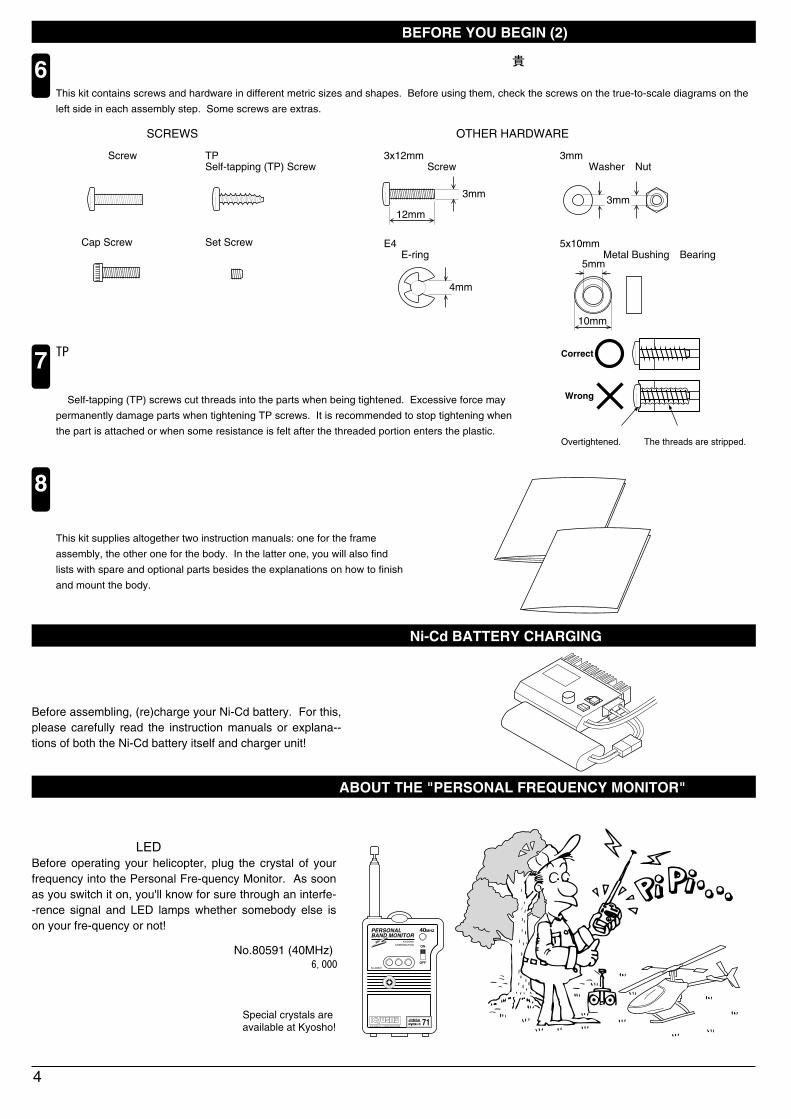
TPビスは、部品にネジを切りながらしめつけるビスです。しめこみが固い場合がありますが、部品が確実に固定されるまでしめこんでください。 ただし、しめすぎるとネジがきかなくなりますので、部品が変形するまでしめないでください。 Self-tapping (TP) screws cut threads into the parts when being tightened. Excessive force may
permanently damage parts when tightening TP screws. It is recommended to stop tightening when
the part is attached or when some resistance is felt after the threaded portion enters the plastic.
7
ビスがきかないThe threads are stripped.
しめすぎOvertightened.
Correct
Wrong
キットには、形や長さが違うビスや小物部品が多く入っています。説明書には原寸図がありますので確認してから組立ててください。また、ビス類は多めに入っているものもありますので、予備としてお使いください。This kit contains screws and hardware in different metric sizes and shapes. Before using them, check the screws on the true-to-scale diagrams on the
left side in each assembly step. Some screws are extras.
6
このキットの説明書は、“フレーム編”+“ボディ編”で構成されています。ボディの組立て、およびスペアパーツリストは、“ボディ編”の説明書に記載されていますので合わせてお読みになり、正しくお使いください。This kit supplies altogether two instruction manuals: one for the frame
assembly, the other one for the body. In the latter one, you will also find
lists with spare and optional parts besides the explanations on how to finish
and mount the body.
8
●ビスの種類 SCREWS
ビス Screw
キャップビスCap Screw
TPビスSelf-tapping (TP) Screw
セットビスSet Screw
●小物部品のサイズ例 OTHER HARDWARE
3x12mm ビス Screw
3mm
12mm
3mm ワッシャー・ナット Washer・Nut
3mm
5x10mm メタル・ベアリング Metal Bushing・Bearing
5mm
10mm
4mm
E4 Eリング E-ring
●6,000
パーソナルバンドモニターについて ABOUT THE "PERSONAL FREQUENCY MONITOR"
愛機の飛行前に、使うバンドのクリスタルをセットしてスイッチオン! 同一バンドの電波をキャッチするとブザー音とLEDの光で警告。Before operating your helicopter, plug the crystal of your frequency into the Personal Fre-quency Monitor. As soon as you switch it on, you'll know for sure through an interfe--rence signal and LED lamps whether somebody else is on your fre-quency or not!
組立前に、ニカドバッテリーの充電をおこないます。ニカドバッテリー、および充電器の取扱説明書をよく読み正しく充電をおこなってください。Before assembling, (re)charge your Ni-Cd battery. For this, please carefully read the instruction manuals or explana--tions of both the Ni-Cd battery itself and charger unit!
PERSONALBAND MONITOR
40MHZ
OFF
ONKYOSHO
CORPORATION
No.80591
JRMSA 71KYOSHO CORPRATION
No.80591 (40MHz)
専用クリスタル別売Special crystals areavailable at Kyosho!
組立説明書
フレーム編
組立説明書
ボディ編

1
2
送信機に単3乾電池を8本入れる。Install 8 AA-size dry batteries intothe transmitter.
電源を入れる。
Turn on the switch.
▲▼同時押し。
Press ▲and▼ buttonsat the same time.
同時押しで通常の画面にもどります。
Press two buttons at the same timeto return regular display.
-(マイナス)を押す。
Press - (minus) button.
-(マイナス)を押す。
Press - (minus) button.
▲を6回押す。(ATVから9回目)
Press ▲ button 6 times.(9 times from ATV)
この表示になりREVの設定は終わりですが、続いてREVOの設定を行います。
When display shows above information,REV setting is completed. Then goesto REVO setting.
この表示になりREVOの設定は終わりです。
When display shows above information,REVO setting is completed.
▲3回押す。
Press ▲ button 3 times.
2回押す。
Press cursor button twice.
この表示になります。
Display shows aboveinformation.
この表示になります。
Display shows aboveinformation.
3回押すと4が点滅します。
When cursor button is pressed3 times, cursor for No. 4 turnson and off.
● ~ は、フルセットに付属のフタバFF6H SUPERプロポセット専用の説明となっています。それ以外のプロポセットを使用される場合は、プロポセット付属の取扱説明書をよくお読みになった上で、下記の作業をおこなってください。
With full sets, explanations in steps ~ are based on the FUTABA FF6H SUPER radio. With other radios, please read their explanations, then do the following settings on your transmitter:
●
送信機のリバーススイッチで、ラダーサーボをリバース(逆転)側にする。レボリューションミキシングをOFFにする。(GY240等の圧電ジャイロ使用時)スロットルスティックが60%の位置で、モーターコントロールアンプがハイになるようにアンプを調整する。
Set the reverse switch for the rudder control to "REVERSE".Switch off the "REVOLUTION MIXING".When piezo gyro, such as GY240, is installed.Set the electronic speed controller so its "high end" function is activated when the throttle control stick is moved up to 60% of its total travel.
●
送信機Transmitter
PUSH
+
-+
- +
-+
- +
-+
- +
-+
-
INH
注意して組立てる所。Pay close attention here!
7 7
5

プロポRadio4
6
3 サーボServo
サーボホーンをはずし、コネクターに番号シールをはる。(7ヶ所)Remove the servo horns. Apply numbered stickers to each of the 7 connectors indicated below.
●
サーボホーンServo Horn
番号シールNumbered Stickers
サーボServo
サーボと同じ形のコネクターSame type of connectoras on servos.
もう一方のコネクターSecond connector.
モーターコントロールアンプElectronic Speed Controller
ジャイロGyro
でコネクターに貼った番号シールと受信機の番号を合わせてさしこむ。送信機の各トリムを中立にする。(4ヶ所)充電してあるニカドバッテリーを、モーターコントロールアンプのバッテリーコネクターにさしこむ。送信機のスイッチを入れてから、受信機のスイッチを入れる。各スティックを動かし、サーボの動作をチェックする。各サーボ、ジャイロが動いたらスイッチはそのままで に進んでください。
Plug the connector with the sticker into terminal No. 3 on the receiver.Center all 4 trims on the transmitter.Plug the charged (!) Ni-Cd battery into the Ni-Cd battery connector on the electronic speed controller.First switch on the transmitter, then the receiver.Move the control sticks and see whether the servo horns move according to your inputs.When all servos move and the gyro functions, proceed to step .
向きに注意Note the direction.
左右どちらでも良いPlug in left or right.
サーボServos
サーボServos
サーボServos
ジャイロGyro
受信機Receiver
受信機スイッチReceiver Switch
モーターコントロールアンプElectronic Speed Controller
バッテリーコネクターNi-Cd Battery Connector
ニカドバッテリーNi-Cd Battery
番号の順に組立てる。Assemble in the specified order.
エレベータートリムElevator Control Trim
スロットルトリムThrottle Control Trim
エルロントリムAileron Control Trim
ラダートリムRudder Control Trim
ラダーRudder Control エルロン
Aileron Control
エレベーターElevator Control
スロットル・ピッチThrottle・Pitch Control
取付け用グロメットは使用しない.Do not use the grommets for servomounting.

6
7 プロポRadio
ジャイロGyro
7
5 モーターコントロールアンプElectronic Speed Controller
スロットルトリムを上まで上げる。送信機のスロットルスティックをスロー(下)にする。 をプロポに付属の調整ドライバーで、時計方向(右)にいっぱいまで回す。この時、 が緑色に点灯している時は、 を反時計方向(左)に回し、 が消灯する所まで回す。又、 が消灯している時は、 を時計方向(右)に回し、 が点灯し始める所より少し戻して消灯させる。
Move the throttle control trim up.Move the throttle control stick on the transmitter down.Rotate entirely clockwise using the adjust-ment driver supplied with every radio. will light on green. Now, rotate counter-clockwise until goes out. Or, rotate clock-wise until starts flashing.
アイドルポイント(スロー)の調整
スロットルスティックを60%位の位置まで上げる。 を反時計方向(左)に回し、 が赤く変化した所で止める。スロットルトリムを下まで下げる。
ハイポイント(ハイ)の調整
Idle point (low end) adjustment
Move the throttle control stick up to the point that would represent 60% of total stick travel.Rotate counterclockwise until lights on red. Move the throttle control trim
High point (high end) adjustment
調整ドライバーAdjustment Driver
100%
60%
75にセットする。Set to 75.
“NOR”側にセットする。Set to "NOR".
“OFF”側にセットする。Set to "OFF".
スロットルスティックは中央にする。エルロン・エレベーター・ラダーのトリムを中央にする。サーボホーンは図の形の物を使用し、また、使用する穴に注意する。
Move the throttle control stick to neutral.Set the aileron, elevator, and rudder trims to neutral.Only use servo horns like the ones shown, and note which hole you hook in the linkage.
●リンケージの準備をします。
90°
●Linkage Setup
中央にする。Center.
サーボホーンServo Horn
使用する穴holes that can be used.
使用しないnot used.
AVCS切替AVCS Switch
ジャイロ方向Gyro Direction
ジャイロ感度Gyro Gain

8
9
10
8
テールTail
ラダーサーボRudder Control Servo
2mm
テールスライドアッセンブリーTail Slide Assembly
HH-2
HH-2
101102
2 x 15mm 106
107
1
2 x 15mm ビスScrew
1
2mm ワッシャーWasher
1
レバーブッシュ(C)Lever Bushing (C)
2
2.6 x 10mm キャップビスCap Screw
1
3 x 3mm セットビスSet Screw
2
2.6mm ナイロンナットNylon Nut
3 x 3mm
テールローターアッセンブリーTail Rotor Assembly
2.6 x 10mm
2.6mm
92
この部分にセットビスをしめる。Tighten the set screw into this groove.
の取付け向きに注意。Note the direction for .
9292
が動く程度にしめる。Tighten both 2.6x10mm cap screws ensuring the tail rotor blades still have a little play in the grips.
92
HH-1, HH-3
2
2.6 x 6mm TPビスScrew
2
2.6 x 8mm TPビスScrew
2.6 x 8mm167
2.6 x 6mm
フルセットには含まれています。それ以外は別購入品。Only supplied in full sets.
(ラダーサーボ)(Rudder Control Servo)
使用する袋詰。
Part bags used.注意して組立てる所。Pay close attention here!
102
の位置Note how is installed.
2.6mm ワッシャーWasher
2
2.6mm2.6mm
ビスの長さに注意する。Note the length for each screw.
106106

ラダーリンケージRudder Linkage11
12
13
エレベーターサーボElevator Control Servo
エレベーターリンケージElevator Linkage
27
2mmの穴をあける(例)。Drill holes with the specified diameter (here: 2mm).
9
HH-2
90°
フルセットには含まれています。それ以外は別購入品。Only supplied in full sets.
2mm
116
1
3 x 3mm セットビスSet screw
115
サーボホーンServo Horn
●
6~8mm
図の位置でセットビスをしめる。Finally, tighten the set screw once the set-up is done.
平行Make parallel.
テールリンケージガイドTail Linkage Guide
Eリング(E1.5)E-ring (E1.5)
1
1
ちがう形状のサーボホーンを使用する場合。With other types of servo horns:
HH-1, HH-3
2
2.6 x 6mm TPビスScrew
1
2.6 x 8mm ビスScrew
1
2.6 x 14mm TPビスScrew
2.6 x 8mm
2.6 x 14mm 164
162
(エレベーターサーボ)
2.6 x 6mm
HH-3 ●ちがう形状のサーボホーンを使用する場合。With other types of servo horns:
原寸図True-to-scale diagram.
168A
1
ボールエンド(L)Ball End (L)
1
エレベーターロッドElevator Rod
27
使用する袋詰。
Part bags used.
90°
水平Make horizontal.
115
2.6mm ワッシャーWasher
2
116
部分をカットする。Cut off shaded portion.
2mm
2mm
3 x 3mm
2.6mm
2.6mm
2mm6~8mm
(Elevator Control Servo)
●エレベーターロッド Elevator Rod
約36.5mmapprox. 36.5mm
スロットルスティックを中立にしておく。Move the throttle control stick to the neutral position.
ラダートリムを中立に。Center the rudder control trim.

14
15
16
10
ピッチリンケージPitch Linkage
エルロンサーボAileron Control Servo
27
HH-1, HH-3
2
2.6 x 6mm TPビスScrew
2
2.6 x 8mm TPビスScrew
166
(ピッチサーボ)
2.6 x 8mm
2.6 x 6mm
1
ボールエンド(L)Ball End (L)
1
ピッチリンケージロッドPitch Linkage Rod
169A
HH-3●ちがう形状のサーボホーンを
使用する場合。With other types of servo horns:
HH-1, HH-3
1
2.6 x 8mm ビスScrew
1
2.6 x 14mm TPビスScrew
160
2.6 x 8mm
2.6 x 14mm
158A
2mmの穴をあける(例)。Drill holes with the specified diameter (here: 2mm).
フルセットには含まれています。それ以外は別購入品。Only supplied in full sets.
原寸図True-to-scale diagram.
使用する袋詰。
Part bags used.
2mm6~8mm
27
2.6mm ワッシャーWasher
2
169A
2.6mm
2.6 x 6mm
2.6mm
2mm をカットする。Cut off shaded portion.
ビスの長さに注意する。Note the length for each screw.
(Pitch Control Servo)
90°
ピッチリンケージロッドPitch Linkage Rod
●
approx. 43mm約43mm
スロットルスティックを中立にしておく。Move the throttle control stick to the neutral position.

エルロンリンケージAileron Linkage17
18 ローターヘッドRotor Head
11
1
ボールエンド(L)Ball End (L)
1
エルロンロッドAileron Rod
HH-1, HH-3
153A 27
●ちがう形状のサーボホーンを使用する場合。With other types of servo horns:
HH-3
4
ボールエンド(L)Ball End (L)
2
ピッチリンケージロッドPitch Linkage Rod
スタビライザーロッドStabilizer Rod
2
原寸図True-to-scale diagram.
使用する袋詰。
Part bags used.2mmの穴をあける(例)。Drill holes with the specified diameter (here: 2mm).2mm
をカットする。Cut off shaded portion.
注意して組立てる所。Pay close attention here!
番号の順に組立てる。Assemble in the specified order.
フルセットには含まれています。それ以外は別購入品。Only supplied in full sets.
ロッドの長さは左右同寸法にする。Ensure both rods are equally long.
ロッドの長さはおおよその目安。P16トラッキング調整で微調整する。
27
153A
2mm6~8mm
236
ヒラーコントロールロッドHiller Control Rod
2
237
235
27
(エルロンサーボ)
2.6mm
2
2.6 x 6mm TPビスScrew
2.6mm ワッシャーWasher
2
2.6 x 6mm
2.6 x 6mm
2.6mm
(Aileron Control Servo)
エルロンロッドAileron Rod
●
2セット組立てる(例)。Assemble as many times as specified (here: twice).x2
約47.5mmapprox. 47.5mm
90°
90°
235
235
236
236 23727
27
●ピッチロッド
Pitch Rod 約34mm
approx. 34mm
●スタビライザーロッド
Stabilizer Rod 約20mm
approx.20mm
237
27
27
27
●ヒラーコントロールロッド
Hiller Control Rod約41.5mm
approx. 41.5mm
x2
x2
x2
で使用する。
The adjusting length of the rods are only approximate values. The length may vary according to the model.Fine adjustment is required in tracking adjustment on page 16.
Pitch Rods are attached in Step 21.
で使用する。
Hiller Control Rods are attached in Step 19.
19
で使用する。
Stabilizer Rods are attached in Step 21.
21
21

ローターヘッドRotor Head19
12
HH-3
HH-1ローターヘッドRotor Head20
ローターヘッドRotor Head21
使用する袋詰。
Part bags used.左右同じように組立てる。Assemble left and right sides the same way.
番号の順に組立てる。Assemble in the specified order.
注意して組立てる所。Pay close attention here!
2×15mm キャップビスCap Screw
2mmナットNut
1
1
21 3
2×8mm
マスト Mast
2mm
2×15mm
2×8mm
ヒラ-コントロールロッドは無理な力が加わらない長さまた2本とも同じ長さにする。無理な力が加わるとスワッシュプレートが破損する原因となる。
It is important that the Hillerr
Control Rods are correctly adjusted to fit your machine.Ensure that both rods are of equal length. Incorrect adjustment can cause damage
ヒラ-コントロールロッドHiller Control Rod
スワッシュプレートSwash Plate
ヒラ-コントロールロッドHiller Control Rod
241
27
ピッチロッドPitch Rod
ピッチロッドPitch Rod
スタビライザーロッドStabilizer Rod
スタビライザーロッドStabilizer Rod
プロポRadio22
23
13
プロポRadio
HH-3
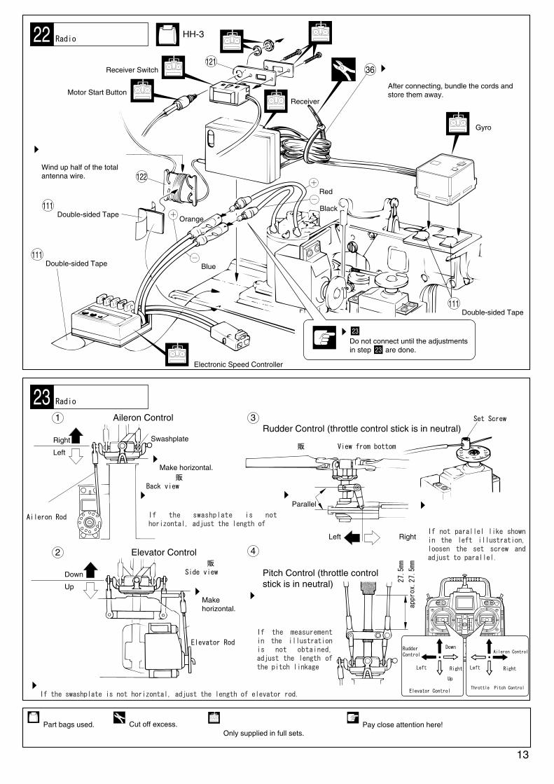
36 コネクター接続後、コードをたばねて固定する。After connecting, bundle the cords and store them away.
121
ジャイロGyro
両面テープDouble-sided Tape
余分をカットする。Cut off excess.
受信機Receiver
アンテナの半分位の長さをまきつける。Wind up half of the total antenna wire. 122
両面テープDouble-sided Tape
モーターコントロールアンプElectronic Speed Controller
両面テープDouble-sided Tape
111
111
111
青Blue
オレンジOrange
黒Black
赤Red
使用する袋詰。
Part bags used.フルセットには含まれています。それ以外は別購入品。Only supplied in full sets.
水平 Make horizontal.
ラダーRudder Control
エルロンAileron Control
エレベーターElevator Control
スロットル・ピッチThrottle・Pitch Control
エルロン Aileron Control1
エレベーター Elevator Control2
右 Right
左 Left
エルロンロッドAileron Rod
スワッシュプレート Swashplate
《後ろから見た図》 《Back view》
スワッシュプレートが水平でない場合、エルロンロッドの長さを調整する。
ダウン Down
アップ Up
《横から見た図》 《Side view》
水平 Make horizontal.
エレベーターロッドElevator Rod
ラダー(スロットルスティックを中立にする)Rudder Control (throttle control stick is in neutral)
3
《下から見た図》 《View from bottom》
平行 Parallel
右 Right左 Left
ピッチ(スロットルスティックを中立にする)Pitch Control (throttle control stick is in neutral)
4
左図のように平行にならない場合、セットビスをゆるめて調整する。
セットビスSet Screw
図の寸法にならない場合、ピッチリンケージロッドの長さを調整する。
約27.5mm
approx.27.5mm
アップ Up
ダウンDown
左Left
右Right
左Left
右Right
モータースタートスイッチMotor Start Button
受信機スイッチReceiver Switch
注意して組立てる所。Pay close attention here!
の調整が終わるまで接続しない。
Do not connect until the adjustmentsin step are done.
23
23
If the swashplate is not horizontal, adjust the length of
スワッシュプレートが水平でない場合、エレベーターロッドの長さを調整する。If the swashplate is not horizontal, adjust the length of elevator rod.
If not parallel like shown in the left illustration, loosen the set screw and adjust to parallel.
If the measurement in the illustration is not obtained, adjust the length of the pitch linkage
24
25
26
メインローターMain Rotor
メインローターMain Rotor
28
2.6mm
注意して組立てる所。Pay close attention here!
14
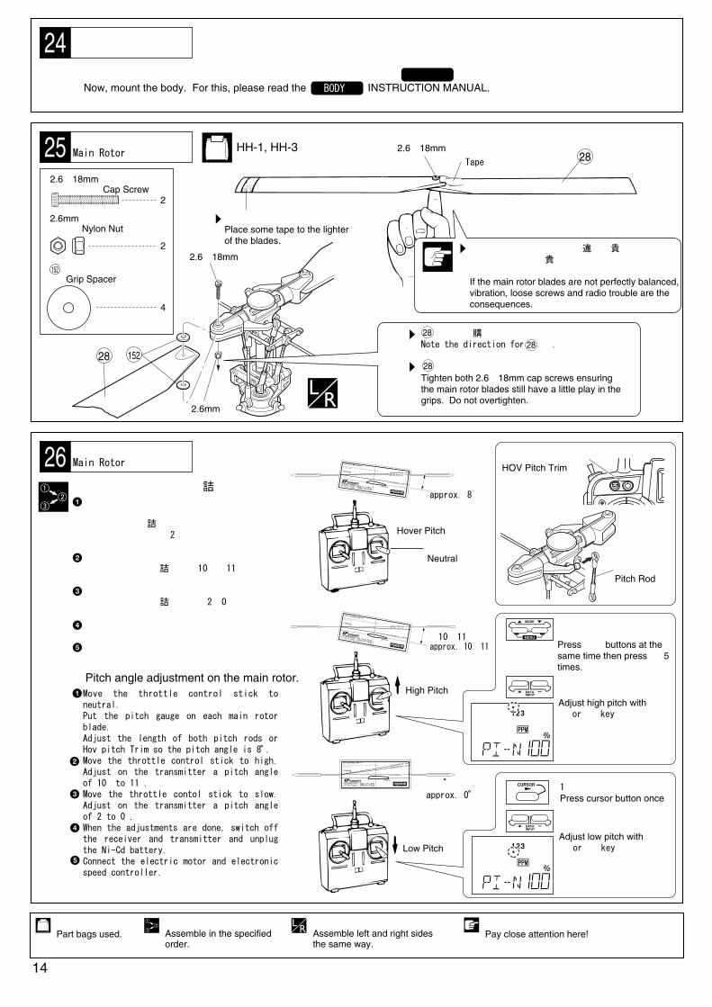
この段階で、ボディを取付けます。ボディの取付けは、組立説明書 をお読みになり、正しく取付けてください。Now, mount the body. For this, please read the INSTRUCTION MANUAL.
●
2
2.6×18mm キャップビスCap Screw
2
2.6mm ナイロンナットNylon Nut
HH-1, HH-3
LOW-PITCH (0°)
ROTOR
HOVER-PITCH (8°)HIGH-PITCH (10°)
ピッチゲージのガイドラインがスタビライザーバーと平行になるまで傾ける。
Only the guideline that is parallel to the stabilizer bar, indicates the pitch angle
on the rotor blades.
GUIDELINE
R
THE FINEST RADIO CONTROL MODELS
約8°
LOW-PITCH (0°)
ROTOR
HOVER-PITCH (8°)HIGH-PITCH (10°)ピッチゲージのガイドラインがスタビライザーバーと平行になるまで傾ける。
Only the guideline that is parallel to the stabilizer bar, indicates the pitch angle
on the rotor blades.
GUIDELINE
R
THE FINEST RADIO CONTROL MODELS 約0
LOW-PITCH (0°)ROTOR
HOVER-PITCH (8°)HIGH-PITCH (10°)
ピッチゲージのガイドラインがスタビライザーバーと平行になるまで傾ける。
Only the guideline that is parallel to the stabilizer bar, indicates the pitch angle
on the rotor blades.
GUIDELINE
R
THE FINEST RADIO CONTROL MODELS
約10~11°
軽い方にデカールをはる。Place some tape to the lighter of the blades.
2.6×18mm テープTape
2.6×18mm
28 152
左右同じように組立てる。Assemble left and right sides the same way.
の取付け向きに注意。Note the direction for .
が動く程度に締め、強く締めすぎないこと。Tighten both 2.6×18mm cap screws ensuring the main rotor blades still have a little play in the grips. Do not overtighten.
2828
28
使用する袋詰。
Part bags used.番号の順に組立てる。Assemble in the specified order.
メインローターピッチ角の調整●
ハイピッチHigh Pitch
ハイピッチ+または-キーで調整するAdjust high pitch with+ or - key
ローピッチ+または-キーで調整するAdjust low pitch with+ or - key
1回押しPress cursor button once
approx. 10~11°
approx. 8°
approx. 0
ホバーピッチHover Pitch
中立位置Neutral
ローピッチLow Pitch
スロットルスティックを中央にする。メインローターにピッチゲージを差し込み、メインローターの角度が約8°になるようにホバーピッチトリム又は、2本のピッチロッドを調整する。スロットルスティックをハイにする。メインローターの角度が約10 ~11°になるように、送信機で調整する。スロットルスティックをスローにする。メインローターの角度が約 2~0°になるように、送信機で調整する。調整が終わったら、受信機、送信機の順番で電源を切り、ニカドバッテリーをはずす。モーターとモーターコントロールアンプのコネクターを接続する。
Move the throttle control stick to neutral.Put the pitch gauge on each main rotor blade.Adjust the length of both pitch rods or Hov pitch Trim so the pitch angle is 8 .Move the throttle control stick to high. Adjust on the transmitter a pitch angle of 10 to 11 .Move the throttle contol stick to slow. Adjust on the transmitter a pitch angle of 2 to 0 .When the adjustments are done, switch off the receiver and transmitter and unplug the Ni-Cd battery.Connect the electric motor and electronic speed controller.
ボディ編
バランス調整が不完全だと振動の原因になり、色々なトラブルの原因になります。安全のため調整は正確に行ってください。If the main rotor blades are not perfectly balanced, vibration, loose screws and radio trouble are the consequences.4
グリップスペーサーGrip Spacer
152
Pitch angle adjustment on the main rotor.●
BODY
ピッチロッドPitch Rod
ホバーピッチトリムHOV Pitch Trim
▲▼同時押し▲5回押すPress ▲▼ buttons at the same time then press ▲ 5 times.

●プロポの操作によるヘリコプターの動きを充分に
理解してから飛行をおこなってください。
Below are listed the reactions of the EP Concept SR according to your inputs.
ヘリコプターの動き HELICOPTER RESPONSE ヘリコプターの動き HELICOPTER RESPONSEプロポの操作
CONTROL STICK POSITION (MODE 1)
15
プロポのスティックの動きとヘリコプターの運動EP CONCEPT SR Control Reactions
ハイHigh
スロットルステッィクThrottle Control Stick
エルロンステッィクAileron Control Stick
エレベーターステッィクElevator Control Stick
ラダーステッィクRudder Control Stick
スローLow
右Right
ダウンDown
アップUp
モーターの回転が上がりメインローターブレードの
ピッチが大きくなり上昇する。
Rpm (electric motor) and pitch (main rotor) increase. As a result, helicopter lifts up.
モーターの回転が下がりメインローターブレードの
ピッチが少なくなり下降する。
Rpm (electric motor) and pitch (main rotor) decrease. As a result, helicopter descends.
左Left
右Right
左Left
2
1
左へ移動。
Moves to the left.
左へかたむく。
Tilts to the left.
2
1
右へ移動。
Moves to the right.
右へかたむく。
Tilts to the right.
1
2
前進または
スピードがあれば降下。
Moves forward. With airspeed, helicopter descends.
1
2
1
2
後進またはブレーキ
スピードがあれば上昇。
Moves backward. With airspeed, helicopter lifts up.
1
2
1
2
2 1
テールローターのピッチを変えることで
機首を左へ振らせる。
By changing pitch on tail rotor, nose moves left.
テールローターのピッチを変えることで
機首を右へ振らせる。
By changing pitch on tail rotor, nose moves right.
調整・飛行させる前にかならずお読みください。 Prior to adjusting & operating, observe the following:
●メインローターが回転しますので、調整・飛行は周りに人がいない屋外でおこなってください。CAUTION: Always operate the helicopter outdoors out of people's reach as the main rotor rotates at high rpm!
●機体の調整中は接触事故等を防ぐため、必ず機体から3m以上離れてください。CAUTION: While adjusting, stand at least 3m apart from the helicopter!
●機体の破損等を防ぐため、スロットルスティックの操作はスローから少しずつ上げてください。CAUTION: For injury prevention, move the throttle control stick only slowly from low to high!
注意
●プロポの電源スイッチを入れる時、または切る時は必ず下記の順番を守ってください。
When switching the radio ON or OFF, always proceed in the following order:
スロットルスティックをいちばん下(スロー)まで下げる。
送信機のスイッチを入れる。
ニカドバッテリーのコネクターをモーターコントロール
アンプと接続する。
受信機のスイッチを入れる。
モータースタートスイッチを押す。
1
2
3
4
5
スイッチを入れる時
受信機のスイッチを切る。
ニカドバッテリーのコネクターをはずす。
送信機のスイッチを切る。
1
2
3
スイッチを切る時
First, move the throttle control stick (transmitter) entirely to slow.Next, after switching on the transmitter, plug the Ni-Cd battery into the electronic speed controller.Then, switch on the receiver.Finally, push the motor start switch (on electronic speed controller).
1
2
3
4
5
When switching ON:
First, switch off the receiver.Next, unplug the Ni-Cd battery from the electronic speed controller.Finally, switch off the transmitter.
1
2
3
When switching OFF:

16
トラッキング調整Tracking Adjustment
飛行前のチェックChecklist before flying
でモーターが止まりピッチ角が少なくなる。
ピッチロッドPitch Rod
角度が増える。Pitch angle increases.
角度が減る。Pitch angle decreases.
With ,the electric motor stopsand the pitch angle decreases.
でメインローターが回転しピッチ角が多くなる。
With ,the main rotor rotates and the pitch angle increases.
でスワッシュプレートが後ろにかたむく。 With ,the swashplate tilts back.
でスワッシュプレートが前にかたむく。 With ,the swashplate tilts fore.
でスワッシュプレートが右にかたむく。 With ,the swashplate tilts right.
でスワッシュプレートが左にかたむく。 With ,the swashplate tilts left.
でスライドリングが左に移動。
With ,the slide ring moves left.
でスライドリングが右に移動。
With ,the slide ring moves right.
機体を固定するために1kg程度の重りをのせる。または、トレーニングスタンドを使用する。
Place a weight of about 1kg on the skids or use Kyosho's training stand to prevent the helicopter from lifting off.
確認後、回転部分のならし運転をします。スロットルスティックを中央ぐらいまで上げて、ニカドバッテリー内の電気がなくなるまでモーターを回してください。
●
After confirming each control stick movement, move the throttlecontrol stick halfway up to run the electric motor. Break in all rotating parts until the Ni-Cd battery runs down.
3~5m
左右のメインローターブレードのピッチ角をそろえることをトラッキング調整といいます。The tracking adjustment consists in making the pitch angle for both main rotor blades equal.
●
スロットルスティックを少しずつ上げ機体を真横から見る。Slowly move the throttle control stick up. Look at the blades directly from the side.
2枚のメインローターが、If both main rotor blades look like in,
のように1枚に見えればOK。
(both blades travel in the same plane), no further adjusting is needed.
のように2枚に見える時は、下記の調整をおこなう。
(both blades track separately), further adjusting is needed.
デカールを貼ったローターを基準にして、もう一方のローターが、Take the blade with the decal as a base.
下に見える時はピッチロッドのボールエンドを右に1/2回転回す。
If the other blade (without decal) tracks lower, rotate the ball end of the pitch rod half a turn right.
上に見える時はピッチロッドのボールエンドを左に1/2回転回す。
If the other blade (without decal) tracks higher, rotate the ball end of the pitch rod half a turn left.
以上の調整を のようになるまでおこなってください。Proceed the same way until both main rotor blades track as in .
重りWeight

17
ホバリング練習(1)Hover-Lesson 1
トリム調整Trim Adjustment
●浮上する時の機体の傾きをトリムレバーで調整します。Correct any yawing, rolling or pitching of the helicopter during take offs with the trims.
● 機体が浮上しようとする時、下図の ~ のように傾く時は、送信機のそれぞれのトリムレバーを ~ の方向に調整します。As the engine speed increases and the helicopter is close to taking off,the following tendencies may be noticed for the helicopter to yaw( or ), to roll ( or ) or to pitch ( or ) instead of lifting straight up. If this happens, adjust the different trims on the transmitterso the helicopter lifts straight up.
●ホバリング練習の前に、次のことを覚えておくと、上達が早くなります。Observe the following before practicing the hover. It will make things a lot easier!
機体は、風にまっすぐ向けること。Direct the helicopter into the wind.
風 Wind
テール部は見ずに、機首を見ること。Do not watch the tail, watch the nose of the helicopter.
着地する時は、前傾姿勢で。
注意して組立てる所。Pay close attention here!
調整や、練習飛行は、無風または微風の時におこなう。Adjust and practice flying only when there is a weak wind or no wind.
横風や、追い風は、操縦が難しくなります。With lateral and tail winds, operation becomes difficult.
後ろから着地すると、メインローターや、テールブームが破損しやすくなります。When landing, the helicopter touches ground first with the front. If touching ground first with the tail, the main rotor or tail boom could be damaged.

18
ホバリング練習(2)Hover-Lesson 2
ホバリング練習(3)Hover-Lesson 3
●ヘリコプターをホバリングさせるには、いつも操縦していることが必要です。操縦している指が、自然に反応するように、根気よく練習してください。Hovering necessitates constant control. Repeat practicing the hover until your fingers get used to operation on the transmitter.
ヘリコプターを風上に向けて置き、その後方に立つ。スロットルスティックを少しずつ上げ、機体が5~10cmぐらい浮上したら、スロットルスティックを少しずつ下げ着陸させる。Direct the helicopter into the wind. Stand behind the helicopter.Raise the throttle control stick little by little and lift up to a height of 5-10 cm. Then decrease engine speed and safely land the helicopter.
この練習を繰り返し、高度を少しずつ上げていく。次に浮上したら、前方に着地するように操縦する。Repeat this exercise and step by step increase the altitude. Next, tryto land the helicopter a little ahead from where you lifted off.
操縦に慣れたら、空中でホバリングできるように練習する。機体が次にどのような動きをするかを考えスティック操作を先へ先へと行うと良い。Once you master these basic controls, you can proceed to the hover.You must constantly anticipate into which direction the helicopter maydrift and move the sticks accordingly beforehand.
前進Forward
左Left
右Right
後退Backward
風Wind
●ホバリングさせることができたら、次に下記の練習をしてください。上空で飛行させる時に必要な練習です。Once you master the hover, proceed to the following exercises,proving indispensable for operating the helicopter at high altitude.
平行移動Lateral Movement
側面ホバリングHover from the side
対面ホバリングHover from the front
19
モーターの交換Electric Motor Replacement
マストの交換Mast Replacement
上空飛行High Altitude Flight
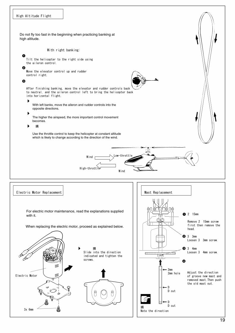
左旋回の場合は、エルロン・ラダーが逆になる。With left banks, move the aileron and rudder controls into theopposite directions.
●上空旋回飛行を練習します。初めのうちは、機速が速くなりすぎないように注意してください。Do not fly too fast in the beginning when practicing banking athigh altitude.
右旋回の場合 With right banking:
エルロンで機体を右にかたむける。Tilt the helicopter to the right side using the aileron control.
エレべーターをアップ、ラダーを右。Move the elevator control up and rudder control right.
旋回が終わったら、エレベーター、ラダーをニュートラルにし、エルロンを左にし機体を水平にする。After finishing banking, move the elevator and rudder controls back to neutral, and the aileron control left to bring the helicopter backinto horizontal flight.
2mmの穴2mm hole
向きに注意Note the direction
DカットD cut
DカットD cut
各舵の大きさは、速度が早くなるほど大きくなる。The higher the airspeed, the more important control movementbecomes.
パワー小Low-throttle
風Wind
パワー大High-throttle 風
Wind
●モーターを交換する時は、下図のように取付けてください。When replacing the electric motor, proceed as explained below.
図の方向によせて取付ける。Slide into the direction indicated and tighten the screws.
モーターElectric Motor
3x 6mm
風向きにより高度が変化するので、スロットルコントロールで高度を一定に保つようにする。Use the throttle control to keep the helicopter at constant altitude which is likely to change according to the direction of the wind.
● モーターのメンテナンスについては、モーターの説明書をお読みください。For electric motor maintenance, read the explanations supplied with it. 2×15mmビスを外しヘッ
ドを外す。Remove 2×15mm screw first then remove the head.
3×3mmビスを緩める。Loosen 3×3mm screw.
3×4mmビスを緩める。Loosen 3×4mm screw.
新品のマストの溝と交換するマストの溝を合せ、そのまま押し出す。Adjust the direction of groove new mast and removed mast.Then push the old mast out.
注意して組立てる所。Pay close attention here!
20
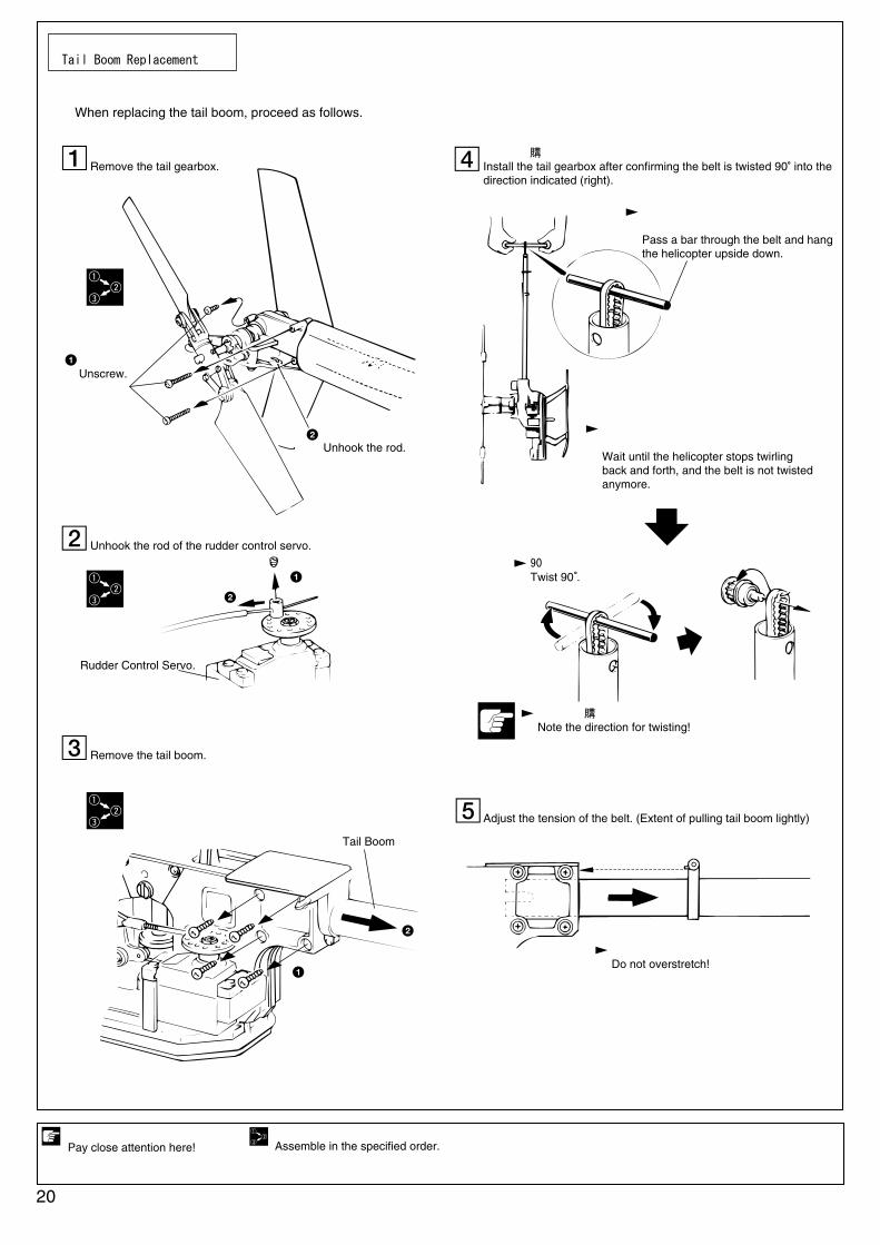
テールブームの交換Tail Boom Replacement
●テールブームを交換する時は、下図のようにおこなってください。When replacing the tail boom, proceed as follows.
テールギヤボックスをはずす。Remove the tail gearbox.
ラダーサーボのロッドをはずす。Unhook the rod of the rudder control servo.
テールブームをはずす。Remove the tail boom.
ベルトの向きを合わせて、テールギヤボックスを取付ける。Install the tail gearbox after confirming the belt is twisted 90 into thedirection indicated (right).
ベルトの張り調整をする。(軽く引く程度)Adjust the tension of the belt. (Extent of pulling tail boom lightly)
ビスをはずす。Unscrew.
ロッドをはずす。Unhook the rod.
ラダーサーボRudder Control Servo.
テールブームTail Boom
ベルトにドライバーや棒などを通し、機体をぶら下げる。Pass a bar through the belt and hang the helicopter upside down.
ねじる方向に注意!Note the direction for twisting!
90度ねじるTwist 90 .
ベルトのねじれがなくなるように、回らなくなるまで待つ。Wait until the helicopter stops twirling back and forth, and the belt is not twisted anymore.
張りすぎないように注意する。Do not overstretch!
番号の順に組立てる。Assemble in the specified order.

21
スタビライザーバーの交換Stabilizer Bar Replacement
番号の順に組立てる。
Assemble in the specified order.
別購入品
Must be purchasedseparately!
ネジロック剤を塗る。
Apply threadlocker(screw cement).
3×3mm
3×3mm
平行
Parallel
A = A' の長さを均等にする。Make A = A' equal.
4
3×3mm セットビス
Set Screw
スピンドルシャフトの交換Spindle Shaft Replacement
2
1
3
A A'

22
故障?と思う前にTroubleshooting
□ホバリングピッチを8°に調整する。
メインローターが回らない。
配線の接続違い。
アンプの調整不良。 □プロポの説明書を読み、再調整する。
充電不足。 □充電器の説明書を読み、再度放電からおこなう。
□モーター・アンプ・ニカドバッテリーの 接続を再確認する。
モーターの回転が悪い。回転しない。
モーター内のコミュテーターの汚れ。
ブラシとコミュテーターの接触が悪い。 □一度外してつけ直す。
ブラシの寿命。 □ブラシを交換する。
モーターの寿命。 □モーターを交換する。
□ブラシを交換する。
トラッキングが合わない。
ピッチ角が合っていない。
スピンドルシャフトの曲がり。 □スピンドルシャフトを交換。
メインローターグリップ部のベアリングの劣化。
□ベアリングを交換。
メインローターバランスが合っていない。
□バランス調整。
□P16 トラッキング調整。
振動が大きい。
メインマストの曲がり。
アウトプットシャフトの曲がり。 □アウトプットシャフトを交換。
メインローターバランスが合っていない。
□バランス調整。
メインローター固定ビスの締め過ぎ。 □ローターが手で動く程度に締めなおす。
□メインマストを交換。
ラダーが効かない。
ベルトがたるんでいる。
テールローターグリップの向きが逆。 □向きを確認する。
テールローターが逆回転している。 □ベルトのねじる向きを逆にする。
ジャイロの動作方向が逆。 □プロポの説明書を読み、確認する。
□フレームのテールブーム固定ビスが 緩んでないか、確認する。
Problem Cause
Does not lift off.Pitch on main rotor too small.
Electric motor running bad. □Read "Electric motor rotates badly".
Remedy
□Set hover pitch to 8û.
Electric motor rotates badly. Or, does not rotate.
Insufficient brush & commutator contact.Worn brushes. □Replace brushes.Motor lifespan over. □Replace motor.
□Remove and reinstall.
Dirty commutator. □Replace brushes.
Main rotor does not rotate.Incorrect radio connection & installation.
Electronic speed controller not set. □Read radio explanations and reset.Ni-Cd battery not charged. □Read charger unit explanations and try charge
again.
□Are electric motor, electronic speed controller and Ni-Cd battery correctly connected?
Main rotor blades track differently.
Pitch on main rotor different.Bent spindle shaft. □Replace spindle shaft.Worn ball bearings in main rotor grips.
□Replace ball bearings.
Unbalanced main rotor. □Balance out (with tracking tape).Main rotor blade installation reverse. □Reinstall blades.
□Make pitch same.
Strong vibrationBent main mast.Bent output shaft. □Replace output shaft.Unbalanced main rotor.
Overtight screws attaching main rotor blades.
□Retighten so blades have a little play in grips.
□Replace main mast.
No rudder control.Slack belt.Tail rotor grip installation reverse. □Check their direction.Tail rotor rotates into opposite direction. □Twist belt into opposite direction.
Reverse gyro operation. □Read radio instruction manual and check.
□Are screws attaching tail boom to frame loose?
P13 22
P14 26
P14 25
メインローターの取付け向きが逆。 □付けなおす。P14 25
P20
P7 5
P8 9
P13 22
P14
P16
26
P14 25
□Balance out (with tracking tape). P14 25
P14 25
P7 5
P8P20
9
キーNo.Key No. 部品名
袋詰No.Bag No.
使用数 Q'tyDESCRIPTION
3
5
16
17A
18
19
20
21
22
23
24
25
27
28
29
30
31
32
33
34A
35
36
39
40
41
42
43
46
47
48
49
50
51
56A
57
58
59
61
62
63
64
88
89
90
91
92
93
94
95
96
97
98
99
100
101
102
104
105
106
107
111
113
114
スタビライザーブレード
スタビライザーバー
4x10x4mmベアリング
ミキシングベース
ミキシングレバー
サイクリックレバー
レバーブッシュ(A)
レバーブッシュ(B)
サイクリックレバーリンク
2x10mmピン
ピッチロッド
スワッシュプレート
ボールエンド(L)
メインローター
7x14x5mmベアリング
7mmストッパー
ピッチスライダー
ピッチスライドリング
10mm止め輪
メインマスト(ロング)
スライドリングワッシャー
ストラップ(小)
エレベーターレバー
エレベーターリンク
2x14mmピン
4.8mmボール(A)
4.8mmボール(B)
プーリーストッパー
ベルトガイド
プーリー(A)
4x8x4mmベアリング
プーリーシャフト
エレベーターレバーシャフト
サブフレーム(B)
ピニオンギヤ(16T)
メインギヤ
アイドルギヤ
アイドルシャフト
7x14x3.5mmベアリング
ワンウェイベアリング
ワンウェイシャフト
テールローターグリップ(A)
テールローターグリップ(B)
テールセンターハブ
3x6x2.5mmベアリング
テールローター
ボールエンド(S)
テールPCプレート
テールピッチリング
6x10x3mmベアリング
テールスライドブッシュ
テールギヤボックス(L)
テールギヤボックス(R)
プーリー(B)
テールピッチレバー
レバーブッシュ(C)
テールブーム
ベルト
PCパイプ
PCロッド
両面テープ
6mm止め輪
アウトプットシャフト
Stabilizer Blade
Stabilizer Bar
4 x 10 x 4mm Ball Bearing
Mixing Base
Mixing Lever
Cyclic Lever
Lever Bushing (A)
Lever Bushing (B)
Cyclic Lever Link
2 x 10mm Pin
Pitch Rod
Swashplate
Ball End (L)
Main Rotor Blade
7 x 14 x 5mm Ball Bearing
7mm Stopper
Pitch Slider
Pitch Slide Ring
10mm Stopper Ring
Main Mast (long type)
Slide Ring Washer
Strap (small)
Elevator Lever
Elevator Link
2 x 14mm Pin
4.8mm Ball (A)
4.8mm Ball (B)
Pulley Stopper
Belt Guide
Pulley (A)
4 x 8 x 4mm Ball Bearing
Pulley Shaft
Elevator Lever Shaft
Sub Frame (B)
Pinion Gear (16T)
Main Gear
Idle Gear
Idle Shaft
7 x 14 x 3.5mm Ball Bearing
Oneway Bearing
Oneway Shaft
Tail Rotor Grip (A)
Tail Rotor Grip (B)
Tail Center Hub
3 x 6 x 2.5mm Ball Bearing
Tail Rotor Blade
Ball End (S)
Tail PC Plate
Tail Pitch Ring
6 x 10 x 3mm Ball Bearing
Tail Slide Bushing
Tail Gear Box (L)
Tail Gear Box (R)
Pulley (B)
Tail Pitch Lever
Lever Bushing (C)
Tail Boom
Belt
PC Pipe
PC Rod
Double-sided Tape
6mm Stopper Ring
Output Shaft
●
●
●
●
●
●
●
●
●
●
●
●
●
●
●
●
●
●
●
●
●
●
●
●
●
●
●
●
●
●
●
●
●
●
●
●
●
●
●
●
●
●
●
●
●
●
●
●
●
●
●
●
●
●
●
2
1
4
1
2
2
2
2
2
2
1
1
15
2
1
1
1
1
1
1
1
4
1
1
2
1
4
2
2
1
6
1
2
1
1
1
1
1
2
1
1
2
2
1
4
2
2
1
1
1
1
1
1
1
1
1
1
1
1
1
1
1
1
キーNo.Key No. 部品名
袋詰No.Bag No.
使用数 Q'tyDESCRIPTION
115
116
117
121
122
151
152
153A
154
155
156
157
158A
160
162
164
166
167
168A
169A
170
172
174
206
228
229
230A
231
234
235
236
237
238
239
240
241
247
251
255
テールリンケージガイド
Eリング(E1.5)
テールローターシャフト
スイッチプレート
アンテナリーディングプレート
メインローターグリップ
グリップスペーサー
エルロンロッド
メインフレーム(L)
メインフレーム(R)
エレベーターリンク(F)
ピッチレバー
サーボマウント(A)
サーボマウント(B)
サーボマウント(C)
サーボマウント(D)
サーボマウント(E)
サーボマウント(F)
エレベーターロッド
ピッチリンケージロッド
サブフレーム(A)
モーターベース
スタビライザーホルダー
モーターピニオン 15T
スピンドルシャフト
Oリング(4φ)
スピンドルシャフトカラー
シーソー
2×3×4mmカラー
ピッチロッド
スタビライザーロッド
ヒラーコントロールロッド
ローターヘッド(シーソータイプ)
ヒラーコントロールレバー
ヒラーコントロールレバーカラー
ヒラーコントロールボール
ドーム
3×6×2.5mmカラー
Sパワーモーター
Tail Linkage Guide
E-ring (E1.5)
Tail Rotor Shaft
Switch Plate
Antenna Leading Plate
Main Rotor Grip
Grip Spacer
Aileron Rod
Main Frame (L)
Main Frame (R)
Elevator Link (F)
Pitch Lever
Servo Mount (A)
Servo Mount (B)
Servo Mount (C)
Servo Mount (D)
Servo Mount (E)
Servo Mount (F)
Elevator Rod
Pitch Linkage Rod
Sub Frame (A)
Motor Base
Stabilizer Holder
Motor Pinion 15T
Spindle Shaft
O-ring(4φ)
Spindle Shaft Collar
Seesaw
2×3×4mm Collar
Pitch Rod
Stabilizer Rod
Hiller Control Rod
Rotor Head (Seesaw)
Hiller Control Lever
Hiller Control Lever Collar
Hiller Control Ball
Dome
3×6×2.5 mm Collar
S Power Motor
2
2
2
3
3
3
3
3
3
3
3
3
3
3
3
3
3
3
●
●
●
●
●
●
●
●
●
●
●
●
●
●
●
●
●
●
●
●
●
●
1
1
2
1
1
2
4
1
1
1
1
1
1
1
1
1
1
1
1
1
1
1
2
1
1
2
2
1
2
2
2
2
1
2
2
2
1
4
1
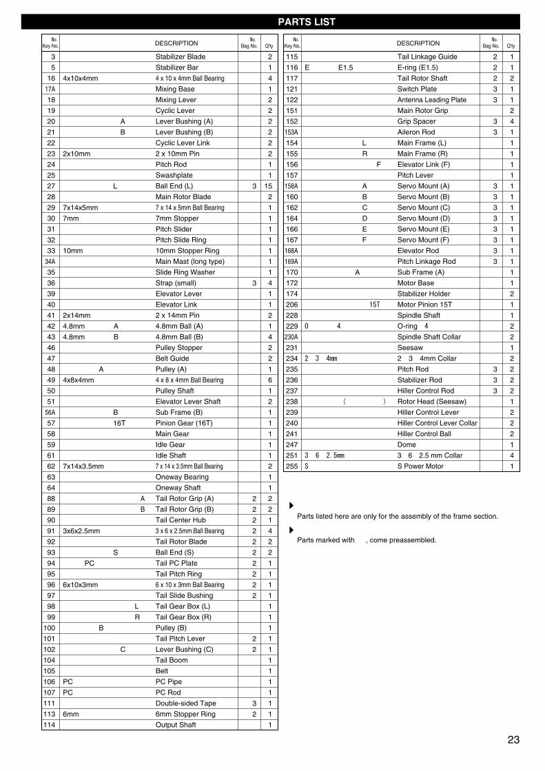
23
パーツリスト PARTS LIST
3
3
2
2
2
2
2
2
2
2
2
2
2
2
3
2
このリストは、フレーム部分のみのリストです。
Parts listed here are only for the assembly of the frame section.
●は、組立済みのパーツです。
Parts marked with ● , come preassembled.

2316
22
EH
-11
EH
-9
28E
H-1
5
2×15
mm
2×6m
m2m
m
2mm
2×6m
m
2.6×
18m
m
2.6×
6mm
2.6m
m
2.6m
m
2×10
mm
3×4m
m
2×8m
m
3×4m
m
2mm
2119
EH
-10A
EH
-10A
2018
17A
Afr
om
EH
-103
A24
EH
-12
25
153A
EH
-103
A
EH
-20
27
24
EH
-23
EH
-34
EH
-20
27
EH
-20
27
EH
-20
27
EH
-20
27
EH
-20
27
EH
-20
27
EH
-20
27EH
-20
27
EH
-20
27
EH
-20
27
EH
-24
43E
H-2
027
EH
-20
27E
H-2
443
236Z
1012
-09
236Z
1012
-09
237Z
1012
-09
237Z
1012
-09
239E
H-1
22
240E
H-1
22 251E
H-1
21
251E
H-1
22
247E
H-1
21
240E
H-1
22 239E
H-1
22
238E
H-1
21
251E
H-1
21
231Z
1012
-06
251E
H-1
22
235Z
1012
-09
235Z
1012
-09
230A Z
1012
-04
229Z
1012
-05
229Z
1012
-05
228Z
1012
-04
241E
H-1
22
234Z
1012
-09
241E
H-1
22234
Z10
12-0
6
230A Z
1012
-04
151E
H-9
4
152E
H-9
4
152E
H-9
4

111
EH-95A
EH-26
51
2.6x 8mm
2.6x 8mm
2.6x 14mm
EH-95A
EH-97
25570975
EH-99
EH115
2.6x 8mm
3x4mm
3x 6mm
EH-33
57
3x 4mm
1903
49
EH-98
EH-95A
3x 12mm
33353231
EH-18
EH-20
27
EH-103A
EH-24
43
EH-24
42
2x 8mm
464847EH-27
3x 3mm
1903
49
EH-29
50
41
EH-96
EH-103A
EH-20
27
2x 8mm
EH-24
43
EH-22
393x 4mm
EH-66A
34A
EH-16
29
EH-17
30
2.6x 10mm(x7)
2.6x 12mm
2.6x 8mm
2.6x 14mm
EH-26
51
EH-95A
EH-95A
EH-95A
2.6x 8mm
2.6x 8mm
EH-34
58
96890
63
EH-39
64
3x 3mm
EH-37
62
EH-35
59
1903
49
EH-36
61
1903
49
EH-32A
56A
2.6x 14mm
H-3072
167
155
168A
162
164
206
172
156
40EH-96
17015
7
169A
158A
160
166
EH-97
154
25

EH-44
2x 8mm
2.6x 10mm
89
EH-41
88
922.6mm
EH-42
117
90
EH-43
91
3x 3mm
EH-45
93
EH-46
94
2x 5mm
EH-47
113
95
96
97
2x 6mm
EH-48
99
EH-64
EH-49
101
102
2mm
2x 15mm
1903
49
47
100
EH-27
3x 3mm
EH-27
461903
49EH-48
98
2mm
105EH-51
EH-54
106
107
104EH-50
EH-54
115
116
3x 3mm
114
26

取扱いの注意 OPERATING YOUR MODEL SAFELY
Always check the dry batteries in the radio!When the dry batteries get weaker, transmission and reception of the radio decrease. You may lose control of your model when operating it under such condition. This may lead to accidents!
Operate the helicopter in spacious areas with no people around! Do NOT operate it:1. in places where children and many people gather!2. in residential districts and parks!3. indoors and in limited space!4. when there is a strong wind or when it is raining!* Non-observance may account for personal injury and property damage!
When the model is behaving strangely . . .!Immediately stop the model and check the reason. As long as the problem is not cleared, do NOT operate it! This may lead to further trouble and unforeseen accidents!
●周囲に人がいなくて、広い安全な場所で! 1. 近くに小さな子供がいたり、人の多い場所では飛行させない。
2. 民家の近くや公園などでは飛行させない。
3. 室内やせまいところでは飛行させない。。
4. 強風時、雨天時には飛行させない。
※人にケガをさせる原因になります。また、物をこわしたり、
他人の迷惑になります。
●飛行前に、ビス等のゆるみをチェックする。
●プロポ関係の電池残量は常にチェックする。 電池が減ってくると電波の送・受信が弱くコントロール ができなくなり、墜落や事故の原因になります。
●近くで無線操縦模型を楽しんでいる人がいる。 同じバンドでの同時飛行はできません。電波が混信して
コントロールができなくなり、墜落や事故の原因になります。
ビス1本のゆるみが事故につながります。
Before flying, check all screws for looseness!May loose screw may account for accidents!
●ニカドバッテリーを充電する時は、ニカドバッテリー および充電器の説明書をよく読んで正しく行なう。 充電中は、ニカドバッテリー、充電器が発熱する。
燃えやすい物の上での充電は、火災等の原因になります。
Before charging, please carefully read the explanations of the Ni-Cd battery and charger unit! While charging, the Ni-Cd battery and charger unit get hot!NEVER charge on top of or near easily inflammable material as this will result in fires!
●ニカドバッテリーには、有害重金属が使用されている。火中に投げ入れると、破裂等の原因になります。
Ni-Cd batteries use heavy metals that are noxious to health!NEVER throw them into fires as they will explode!
●不要になったニカドバッテリーは、捨てずに販売店に 返却する。
ALWAYS return disused Ni-Cd batteries to the shop! Do NOT dispose of them into the usual waste stream!
●ニカドバッテリーをショートさせない。1. 分解、改造は絶対にしない。
2. コードが、回転部分に接触しないようにする。
NEVER short out Ni-Cd batteries!1. Do NOT disassemble or modify Ni-Cd batteries!2. Ensure the cords do NOT trail into rotating and moving parts!
●亀裂や傷のついた部品は、新品と交換する。墜落や事故の原因になります。
Replace parts with defects or having cracks with new parts!Defect parts lead to accidents and crashs!
●飛行直後は、モーターやニカドバッテリーが熱くなっている。冷えるまでは、触らないこと。
After operation, the electric motor and Ni-Cd battery are hot!Do NOT touch them until they cool down!
●回転しているローターには近づかない。接触事故を防ぐために、3m以上機体から離れること。
NEVER get close to the rotor when spinning at high speed!Stand at least 3m away from the rotor to prevent injury!
27
CAUTION: Do NOT operate the helicopter in the following places and situations: (Non-observance may lead to accidents!)
次のような時、場所では飛行させない。思わぬ事故の原因になります。
注意
CAUTION: in order to avoid accidents and personal injury, be sure to observe the following:事故やケガ等の危険防止のため、次のことを必ずお守りください。
注意
Keep in mind that people around you may also operate a radio control model!NEVER share the same frequency with somebody else at the same time! Signals will be mixed and you will lose control of your model.This may lead to accidents!
●へりの動きがおかしい??とき。 すぐに飛行を中止しておかしい原因を調べる、原因不明のまま
飛行させると、思わぬ故障や事故の原因になります。
3m ~

スペアパーツ SPARE PARTS
品番 パーツ名 内容(キーNo.と入数) No. Part Names Quantity
品番 パーツ名 内容(キーNo.と入数) No. Part Names Quantity
EH-54 106 107 115 116 x 1テールリンケージTail Linkage
450
EH-64 114 x 1テールアウトプットシャフトTail Output Shaft
200
EH-66A ロングマストLong Mast 34A x 1 1800
EH-94
151 x 2 152 x 42.6x18mmキャップビス x 2 Cap Screw2.6mmナイロンナット x 2 Nylon Nut
メインローターグリップ(SR)Main Rotor Grip (SR)
550
EH-95A 157 158A 160 162 164 166 167x 1
サーボマウント(SR)Servo Mount (SR)
650
EH-96 40 156 x 1 41 x 2エレベーターリンク(SR)Elevator Link (SR)
400
EH-97 154 155 x 1メインフレームセット(SR)Main Frame Set (SR)
1400
EH-98 170 x 1サブフレーム A(SR)Sub Frame A (SR)
1500
EH-99 172 x 1モーターベース(SR)Motor Base (SR)
450
EH-115 206 x 1モーターピニオン(15T)Motor Pinion (15T)
500
24 153A 168A 169A x 1 27 x 3サーボリンケージセット(SR)Servo Linkage Set (SR)
EH-103A 500
70975 255 x 1SパワーモーターS Power Motor
3000
4x8x2.5mm Oリング4x8x2.5mm O-ring
1903 49 x 24x8x3mmベアリング4x8x3mm Ball Bearing
700
EH-2 3 x 2スタビライザーブレードStabilizer Blade
700
EH-3 4 x 2スタビホルダー(3.5g)Stabilizer Holder (3.5g)
1000
EH-4 5 x 2スタビライザーバーStabilizer Bar
400
EH-9 16 x 24x10x4mmベアリング4x10x4mm Ball Bearing
1000
EH-10A 17A x 1 18 19 20 21 x 2ミキシングレバーMixing Lever
600
EH-11 22 23 x 2サイクリックレバーリンクCyclic Lever Link
400
EH-12 25 x 1スワッシュプレートアッセンブリーSwashplate Assembly
2200
EH-15 28 x 2メインローターMain Rotor
2000
EH-16 29 x 17x14x5mmベアリング7x14x5mm Ball Bearing
550
EH-17 30 x 17mmストッパー7mm Stopper
400
EH-18 31 32 33 35 x 1ピッチスライダーPitch Slider
550
EH-122 239 240 241 251 x 2ヒラーコントロールレバーセット(シーソーヘッド)Hiller Control Lever Set
600
EH-20 27 x 10ロッドエンド(L)Rod End (L)
400
EH-22 39 x 1エレバーターレバーElevator Lever
400
EH-24 42 43 x 24.8mmボール4.8mm Ball
300
EH-26 51 x 2レバーシャフトLever Shaft
600
EH-27 48 100 x 1 46 47 x 2プーリーセットPulley Set
1200
Z1012-06 231 x 1 43 234 x 2シーソーSeesaw
1650
Z1012-09 235 236 237 x 2リンケージセットLinkage Set
500
EH-121 238 247 x 1 251 x 2ローターヘッド(シーソーヘッド)Rotor Head(Seesaw Head)
500
EH-29 50 x 1プーリーシャフトPulley Shaft
350
EH-32A 56A x 1サブフレーム(B)Sub Frame (B)
400
EH-33 57 x 1ピニオンギヤ(16T)Pinion Gear (16T)
450
EH-34 58 x 1メインギヤMain Gear
400
EH-35 59 x 1アイドルギヤIdle Gear
400
EH-36 61 x 1アイドルシャフトIdle Shaft
200
EH-37 62 x 17x14x3.5mmベアリング7x14x3.5mm Ball Bearing
500
28
★ FOR JAPANESE MARKET ONLY.
ボディ関係のスペアパーツは、ボディ編のスペアパーツリストをご覧ください。Body spare parts are listed at the end of each body instruction manual!
EH-39 64 x 1ワンウェイシャフトOneway Shaft
400
EH-41 88 89 x 2テールローターグリップTail Rotor Grip
550
EH-43 91 x 23x6x2.5mmベアリング3x6x2.5mm Ball Bearing
900
EH-44 92 x 2テールローターTail Rotor
400
EH-45 93 x 10ロッドエンド(S)Rod End (S)
450
EH-46 94 x 1テールPCプレートTail PC Plate
450
EH-48 98 99 x 1テールギヤボックスTail Gearbox
550
EH-47 95 96 97 113 x 1テールピッチリングTail Pitch Ring
800
EH-49 101 102 x 1テールピッチレバーTail Pitch Lever
450
EH-50 104 x 1テールブームTail Boom
700
96890 63 x 1ワンウェイベアリングOneway Clutch
800
EH-42 90 x 1 117 x 2テールセンターハブTail Center Hub
500
Z1012-04 228 x 1 230 x 2スピンドルシャフトSpindle Shaft
600
H-3072 111 x 2 両面テープDouble-sided Tape
200
Z1012-05 229 x 2 200
EH-51 105 x 1ベルトBelt
1100
★定価★発送手数料
★定価★発送手数料
200(一律)
200(一律)
70553-7 銀入りレイダウンブラシLay Down Containing Silver 400x 2

29
オプションパーツ OPTIONAL PARTS
★ FOR JAPANESE MARKET ONLY.品番 パーツ名 内容 No. Part Names Description ★定価
★発送手数料
品番 パーツ名 内容 No. Part Names Description
90801スカイヴィクトリー210アンプSky Victory 210 9800
高効率大容量FETアンプHigh efficiency and big capacity FET speed controller
1000Z-8006 振動吸収シートVibration Absorption Sheet
ジャイロ、受信機固定用To attach gyro & RX.
80591 パーソナルバンドモニター(40MHz)Personal Frequency Monitor (40MHz) 6000使用バンド監視用モニター
Checks what frequencies are used.
94402 ロックタイト(中強度)Loctite (medium strength) 900ビスの緩み防止用
Screw thread locking compound
80591-09 40MHz77バンドクリスタル40MHz77 Frequency Crystal 1200
80591-10 40MHz79バンドクリスタル40MHz79 Frequency Crystal 1200
80591-11 40MHz81バンドクリスタル40MHz81 Frequency Crystal 1200
使用するプロポのバンドと同じものが必要Radio & monitor frequencies must be same.
80591-12 40MHz83バンドクリスタル40MHz83 Frequency Crystal 1200
80591-13 40MHz85バンドクリスタル40MHz85 Frequency Crystal 1200
1700KP/KY
蛍光ストラップ(ピンク/イエロー)Fluorescent Strap (pink, yellow) 180 36 と同等
Interchange with 36 .200(一律)
200(一律)
1800EH-73 スペシャルピッチスライダーSpecial Pitch Slider
31 32 33 35 と交換Interchange with 31 32 33 35 .
3800EH-83 メインローターEPハイグレードHigh-grade EP Main Rotor
28 と交換Interchange with 28 .
650EH-104 ミニサーボ用サーボマウントセットServo Mount Set (mini servos)
ミニサーボ搭載時に使用Use with mini servos.
3000EH-92 トレーニングセーフティバーTraining Safety Bar
ホバリング練習に最適When practicing the hover.
EH-120 トレーニングセーフティバー 2Training Safety Bar 2 3000入門者のホバリング練習に最適
When practicing the hover for beginners.
62002162 トレーニングスタンドTraining Stand
ヘリの操縦練習に最適When practicing flights.
500EH-72 ブレードバランサーBlade Balancer
EPコンセプト専用Only for EP Concept.
32002161 ブレードバランサーBlade Balancer
EPからエンジンヘリまで対応For EP & GP helicopters.
500H-3220 カラードトラッキングテープColored Tracking Tape
ローターバランス調整用When balancing main rotor.
600070875 K-スピードヘリスペシャルモーターK-Speed Heli Special Motor
ハイパワーフライト向high-power flights.
800071002 8.4V-RC2400ニカドバッテリー8.4V-RC2400 Ni-Cd Battery
フライト時間の延長にFor longer time flights.
600071705 8.4V-1800スーパーマルチフォースニカドバッテリー8.4V-1800Super Multi Force Nicd Battery
練習フライト向ニカドバッテリーUse when practicing flights.
500EH-114 モーターピニオン(14T)Motor Pinion(14T)
173 と交換Interchange with 173 .
EH-116 モーターピニオン(16T)Motor Pinion(16T) 500206 と交換
Interchange with 206 .
400Z-1004 HPアルミアウトプトシャフトHP Aluminum Output Shaft
2200Z-1006 HPテールドライブプーリーHP Tail Drive Pulley
48 100 と交換Interchange with 48 100 .
Z-1012 Z12HPシーソーヘッドZ12HP Seesaw Head 8800 上空のスタント飛行に最適
700Z-1005 HPアルミプーリー、アイドルシャフトHP Aluminum Pulley・Idil Shaft
50 61と交換Interchange with 50 61.
Best maneuverability during aerobatic flight.
114 と交換Interchange with 114 .
2500056600 アペックス(インフィニティー)Apex (Infinity)
9.6Vバッテリーの充電に最適For charging 9.6V battery.
72501 DCクイックチャージャーIIIDC Quick Charger III 34007.2~8.4V用デジタルピークオートカットオフタイプ
Digital peak auto-cut type for 7.2~8.4V.
72506 マルチチャージャーIIIMulti Charger III 48006~8.4V用デジタルピークオートカットオフタイプ
Digital peak auto-cut type for 6~8.4V.
2900Z-1002 カーボンテールブームCarbon Tail Boom
104 と交換Interchange with 104 .
★定価★発送手数料
96642 4x6mm シムセット4x6mm Sim Set 400
230A と 16 の間に挿入 229 の硬さ調整用Insert between 230A and 16 to adjusttightness of 229 .
71003 9.6V-RC2400ニカドバッテリー9.6V-RC2400 Ni-Cd Battery 9000ハイパワーフライト向ニカドバッテリー
Ni-Cd for high-power flights.
1390 E10.0 6 pcs
R
THE FINEST RADIO CONTROL MODELS
京商株式会社
〒243-0034 神奈川県厚木市船子153
●ユ-ザ-相談室直通TEL.046-229-4115お問い合わせは:月曜~金曜(祝祭日を除く) 10:00~18:00
61920006-5 PRINTED IN JAPAN
1147 2.6x6・2.6x8・2.6x10・2.6x12 5 each1148 3x6・3x8・3x10・3x12・3x14 5 each1149 3x15・3x16・3x18・3x20 5 each1150 4x15・4x20・4x25 5 each
1153 3x6・3x8・3x10 2 each1154 4x8・4x10・4x12 2 each
1157 2x8・2x10 10 each
1160 3x6・3x12・3x14・3x16 3 each1161 3x3・3x4・3x5・3x10 3 each1162 4x4・4x5・4x8・4x12 3 each1163 5x4・5x5・5x6 3 each1164 5x30・5x40 3 each
1171 2mm・2.6mm 10 each1172 3mm・4mm 10 each
1174 3mm 10 pcs1175 4mm 10 pcs
1177 2.6mm 5 pcs1178 3mm 5 pcs1179 4mm 5 pcs
1180 4mm 5 pcs
サラタッピングビスFlat Head Self-Tapping Screw ●200
フランジ付キャップビスFlanged Cap Screw ●200
セットビスSet Screw ●200
フランジ付ナットFlanged Nut ●200
●200
1185 2mm・2.6mm・3mm 10 each1186 4mm・5mm 10 each
1380 E1.5 10 pcs
EリングE-ring ●150
サラ小丸ビスRT/H Screw ●200
ナットNut ●200
ナイロンナットNylon Nut ●200
フランジ付ナイロンナットFlanged Nylon Nut
●200ワッシャーWasher
1381 E2.0 10 pcs1382 E2.5 10 pcs1383 E3.0 10 pcs1384 E4.0 10 pcs1385 E5.0 10 pcs1386 E6.0 10 pcs1387 E7.0 6 pcs
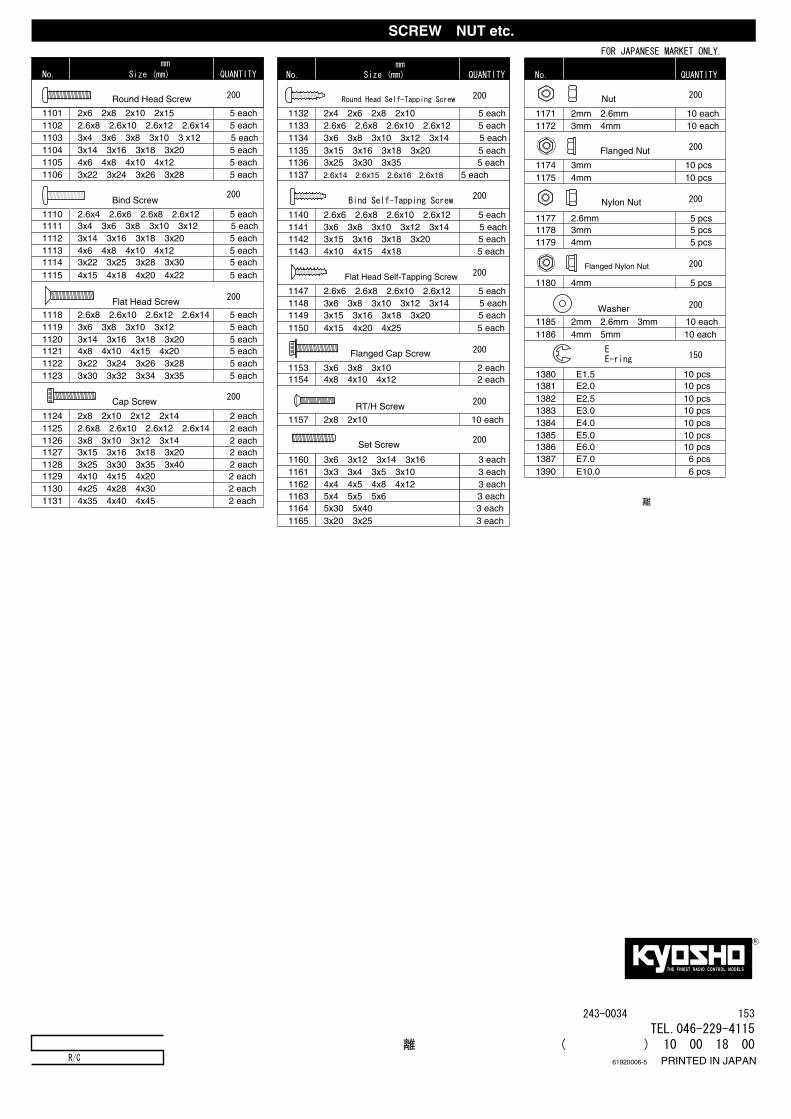
● FOR JAPANESE MARKET ONLY.
※ここに明記された以外のビス、ナット等は『ユーザー相談室』にお問い合わせください。
1101 2x6・2x8・2x10・2x15 5 each1102 2.6x8・2.6x10・2.6x12・2.6x14 5 each1103 3x4・3x6・3x8・3x10・3 x12 5 each1104 3x14・3x16・3x18・3x20 5 each1105 4x6・4x8・4x10・4x12 5 each1106 3x22・3x24・3x26・3x28 5 each
1110 2.6x4・2.6x6・2.6x8・2.6x12 5 each1111 3x4・3x6・3x8・3x10・3x12 5 each1112 3x14・3x16・3x18・3x20 5 each1113 4x6・4x8・4x10・4x12 5 each1114 3x22・3x25・3x28・3x30 5 each1115 4x15・4x18・4x20・4x22 5 each
1118 2.6x8・2.6x10・2.6x12・2.6x14 5 each1119 3x6・3x8・3x10・3x12 5 each1120 3x14・3x16・3x18・3x20 5 each1121 4x8・4x10・4x15・4x20 5 each1122 3x22・3x24・3x26・3x28 5 each1123 3x30・3x32・3x34・3x35 5 each
1124 2x8・2x10・2x12・2x14 2 each1125 2.6x8・2.6x10・2.6x12・2.6x14 2 each1126 3x8・3x10・3x12・3x14 2 each1127 3x15・3x16・3x18・3x20 2 each1128 3x25・3x30・3x35・3x40 2 each1129 4x10・4x15・4x20 2 each1130 4x25・4x28・4x30 2 each1131 4x35・4x40・4x45 2 each
バインドビスBind Screw
●200
サラビスFlat Head Screw ●200
キャップビスCap Screw ●200
ナベビスRound Head Screw ●200
品番 サイズ(mm) 入数(各)No. Size (mm) QUANTITY
1132 2x4・2x6・2x8・2x10 5 each
ナベタッピングビスRound Head Self-Tapping Screw ●200
1133 2.6x6・2.6x8・2.6x10・2.6x12 5 each1134 3x6・3x8・3x10・3x12・3x14 5 each1135 3x15・3x16・3x18・3x20 5 each1136 3x25・3x30・3x35 5 each1137 2.6x14・2.6x15・2.6x16・2.6x18 5 each
バインドタッピングビスBind Self-Tapping Screw
●200
1140 2.6x6・2.6x8・2.6x10・2.6x12 5 each1141 3x6・3x8・3x10・3x12・3x14 5 each1142 3x15・3x16・3x18・3x20 5 each1143 4x10・4x15・4x18 5 each
1165 3x20・3x25 3 each
品番 サイズ(mm) 入数(各)No. Size (mm) QUANTITY
品番 径 入数(各)No. QUANTITY
ビス・ナット類 SCREW・NUT etc.
メーカー指定の純正部品を使用して
安全にR/Cを楽しみましょう。