Embed Size (px)
Citation preview
EPA REGION 6
SURVEILLANCE SECTION
RCRA INSPECTION REPORT
Report Date: January 22, 2010
Inspection Date: May 18, 2009-May 21, 2009 and June 24, 2009-June 26, 2009
Type of Inspection: CEI
Company Name: Clean Harbors El Dorado, LLC
Mailing Address: 309 American Circle, El Dorado, Arkansas 71730
Company Owner: Clean Harbors El Dorado, LLC
Location: El Dorado, Arkansas (Union County)
Type of Industry –
NAICS/SIC 562211/4953
Identification Number: ARD069748192
ADEQ Permit Number: 10H-RN1
Date Put Into ICIS June 29, 2009
Enforcement Officer
________________________________
signature Date
EPA Inspector: David Robertson
________________________________
signature Date
Reviewed by:
________________________________ Signature Date
Clean Harbors
ARD069748192
January 22, 2010 Page 2
INTRODUCTION
On May 18, 2009, I (David Robertson), accompanied by Arkansas Department of
Environmental Quality (ADEQ) Inspectors Penny Wilson and Karen Duke, met with Kathy
Shoemaker of Clean Harbors and explained the nature of the inspection. I presented
credentials to Ms. Shoemaker. I conducted an interim closing conference on May 21, 2009. I,
accompanied by Ms. Wilson, returned to the site on June 24, 2009 and completed the
inspection. I conducted a closing conference on June 26, 2009.
The following is a partial list of people that participated in the inspection:
Table 1
Name Title Telephone Email
David Robertson EPA Inspector 214.665.7363 [email protected]
Penny Wilson ADEQ Inspector 501.682.0868 [email protected]
Karen Duke ADEQ Inspector 870-864-2207 [email protected]
Kathy Shoemaker Senior Compliance
Manager
870.864.3711 [email protected]
Kelly Smith Compliance Specialist 870.864.2282 [email protected]
Dan Roblee Facility Operations
Manager II
870.864.3692 [email protected]
Scot Shoemaker Facility Maintenance
Manager II
870.864.3644 [email protected]
Mildred Boshears Laboratory Manager 870.864.3727 [email protected]
Barry Boshears Facility Operations
Supervisor
870.864.3752 [email protected]
Roosevelt Wilhite Facility Operations
Manger I
840.864.3757 [email protected]
Steve Tollette Facility Operations
Manager II
870.864.3797 [email protected]
Michael Karp Facility Incineration
Manager I
870.864.3685 [email protected]
Scott Kuhn Vice President
Environmental
Compliance
803.691.3426 [email protected]
Kevin Leblanc Contractor EMS USA 337.433.8522 [email protected]
For a complete list see Attachment 26.
I provided Ms. Shoemaker an electronic copy of the U. S. EPA Small Business Resources
Information Sheet. Ms. Kathy Shoemaker, Mr. Scot Shoemaker and I discussed Confidential
Business Information (CBI) procedures. The facility made no CBI claims.
Clean Harbors
ARD069748192
January 22, 2010 Page 3
BACKGROUND
The following background information was pulled from Clean Harbors Part B RCRA
Hazardous Waste Permit application dated October 5, 2007. An electronic version of the
permit application is included as Attachment 38. All future references in this report to the
permit application will reference this copy unless otherwise noted.
This site was formerly owned by Ensco, Inc., and Teris, NA. Clean Harbors purchased Teris in
2006 according to Mr. Scott Kuhn and operates a commercial treatment and storage facility for
hazardous and non-hazardous waste at this site.
The facility employs approximately 248 people at this location and operates 24 hours 7 days
per week according to Ms. Shoemaker. Ms. Shoemaker said Clean Harbors owns
approximately 320 acres but operates on only around 50 acres. Ms. Shoemaker said the facility
can incinerate approximately 40,000-50,000 containers per month, 100 tanker trucks per week
and up to 600,000 pounds per day.
According to the permit application, the facility conducts ten major hazardous waste operations
at this site:
1. A warehouse for receiving and storing containerized wastes.
2. Detached Reactive Storage (DRS) buildings for storage of reactive wastes.
3. Compressed gas storage areas.
4. Tanks for storage of bulk liquid wastes.
5. An incineration complex, including a waste-fired boiler (WFB), two rotary kilns, two
shredders, sludge and bulk solids feeding systems, and treatment recovery processes for
scrubber brines.
6. A Residue Management Building for ash management.
7. Truck and railcar unloading sites.
8. A special waste handling facility for receiving, general repackaging and processing of
lab packs and special wastes.
9. An Aerosol Processing Machine.
10. A brine facility which converts scrubber brine to a high density drilling fluid which is
sold as a commercial product.
The permit application lists residues generated by the facility as: scrubber ash, kiln ash,
refractory debris, secondary combustion chamber (SCC) ash, carbon from water treatment,
empty containers, and debris from spills. The permit application notes that all solid residues
are disposed off site as hazardous waste at the Clean Harbors landfill in Waynoka, Oklahoma.
According to the application, Clean Harbors operates a calcium chloride processing facility to
refine scrubber brines into a saleable product.
As a commercial Treatment, Storage and Disposal Facility (TSD), Clean Harbors receives
wastes from customers including: governments, utilities, industries and individuals. Wastes
Clean Harbors
ARD069748192
January 22, 2010 Page 4
received include: spent solvents, waste oils, chlorinated hydrocarbons, herbicides, insecticides
and various cleanup residues.
Clean Harbors receives liquid hazardous waste in containers, tank trucks and rail cars for
incineration or fuel blending. It also receives solids and sludges in containers for incineration.
Clean Harbors additionally receives aerosol cans and gasses in cylinders for treatment.
Blended fuel is normally burned on-site in the facility’s waste fired boiler.
Clean Harbors manages an on-site wastewater treatment facility to treat groundwater recovered
from on-site recovery wells (exclusive of the high chloride wells discussed in the brine
section), and water collected in their on site retention areas.
Incineration (general information pulled from attached permit application)
The facility operates two rotary kiln incinerators. Kiln #1 began operation at this site in 1977.
The incinerator was converted from a boiler. Kiln #1 was most recently replaced in 1995.
Kiln #2 was installed in 1988 – that unit had been in operation elsewhere prior to
refurbishment and installation in the El Dorado facility. The total incinerator system is a
unique design with no model designation.
The integrated incineration facility receives liquid, solid and sludge in barrels, boxes, pails and
cans, bulk truck, bulk rail, and other containers. The main components of the system include:
preprocessing shredders and feed systems, two rotary kilns, bulk solid feed, direct burn from
containers, an in-line grinder for sludge feed, liquid injection nozzles, ash drops for ash
handling, hot cyclone following each kiln, SCC, waste fired boiler, saturator/condensers, new
scrubber, new demister, ID fan, reheater, baghouse, stack, gas sampling system, brine clarifier
tanks, brine recycling equipment, and gas fired boilers.
The secondary combustion chamber for Kiln #1 was installed as part of a system upgrade in
2001 to assist compliance with the Hazardous Waste Combustion National Emission Standards
for Hazardous Air Pollutions Carbon Monoxide Hydrocarbons (NESHAP CO and HC)
emission standards. Clean Harbors uses fuel oil, used oil, natural gas, or non-hazardous waste
as auxiliary fuel.
Treatment Limitations
The facility cannot treat wastes that are hazardous for metals only, because incineration is not
an approved method for the treatment of metals. The facility does test ash for TCLP metals
annually (Incinerator Ash Profile Attachment 15). According to the facility’s Part B Permit
Application, the Land Disposal Restriction (LDR) notice accompanying residue (ash)
shipments indicate that the LDR has been met for organic constituents but not for inorganic
constituents (Attachment 38; section C-1.e.2). Residue management procedures are outlined in
the facility’s Part B Permit Application (Attachment 38; section C-1.e.2). The facility’s Waste
Analysis Plan (WAP) indicates that wastes resulting from incineration of hazardous wastes
Clean Harbors
ARD069748192
January 22, 2010 Page 5
retain the listings under the “derived from” rule. The “derived from” ash (residue) is sent to
the Clean Harbors landfill in Waynoka, Oklahoma for stabilization as hazardous for all metals.
Brine Generation
The facility uses a calcium chloride brine to "quench" their hot incinerator water (See
Attachments 2, 9, 38 and 48 for process descriptions). The brine comes into direct contact with
listed hazardous waste in the form of incinerator flue gas. The facility incinerates many
wastes, including wastes listed for toxicity (for a list of waste codes associated with incinerated
material see a manifest and LDR notification for the brine filter cake -- Attachment 24).
An excellent process description of the quench and condensing steps generating the brine can
be seen in the facility’s permit application (Attachment 38; section D-5 pages 6-8). After
several quench cycles, the brine becomes too dirty for continued use and it is "spent". The
facility determines the brine is spent by monitoring specific gravity. According to Mr.
Shoemaker, when the specific gravity of the brine is between 0.1 and 0.125 – the brine is
considered spent and hard piped to the brine unit for further processing as described below.
After the brine is spent it goes through a treatment step involving addition of flocculent and
filtering to remove metals, it is concentrated by using steam heated heat exchangers under
vacuum to drive off water. The water is discharged to the atmosphere as steam. Following
concentration by evaporation, the brine is filtered once more to remove sodium chloride.
After reclamation, the brine is sold to oil and gas producers for use as a fracturing agent or
down hole balancing agent (Attachment 9). In both cases the brine is placed into or onto the
land. According to the original documentation received from the facility (later recanted), all
the brine placed into the oil well hole is recovered - as oil and gas exempt fluid - and later
disposed (note: the claim that all brine used down hole is included in the Crowell and Moring
letter dated January 24, 1992, page 4, Attachment 9). Documentation in the form of recent
letters from the brine customers recant the former claim that the brine is recovered (Attachment
49). The letters indicate that a significant portion of the brine is left down hole (Attachment
49). The brine plant operation began in 1990 (Attachment 9). According to a response to an
ADEQ letter, Attachment 9 Tab 2, the main customer for the facility’s brine in 1996 was
Fremont Chemical Company of Riverton, Wyoming. The current main customers for the brine
are Meridian Technologies and Ambar Lone Star Fluid Services. Attachment 49 includes
letters from each of these companies indicating how they use the brine.
Attachment 9 is an important document relating to the brine. Page eight (8) of the first
document gives a list of attachments to Attachment 9 these are summarized as:
- Letters from ADPC&E acknowledging the recycling status of the brine.
- MSDS and product specifications for the brine product.
- Process schematic
- Legal analysis of the recycling program by Crowell and Moring.
- Regulatory analysis by Strategic Environmental Analysis.
Clean Harbors
ARD069748192
January 22, 2010 Page 6
- Approval letter by ADPC&E regarding Ensco’s ferrous metal recovery unit (now
closed) and the scrap metal recycling activities (no longer in use).
- Arkansas Environmental Federation Pollution Prevention/Waste Minimization Award
- Sample from R’s for EPCRA Section 313 release reports.
Following the attachments listed above in Attachment 9 are:
- Correspondence with ADPC&E concerning the brine (Tab 2).
- Analytical Data on the brine (Tab 3).
I encourage anyone reviewing this report to take a close look at Attachment 9.
The facility claims the brine is a commercial chemical product and gets the 261.2 (e)(1)(ii)
exemption; and has a letter from an ADEQ inspector dated 12-20-96 to support that claim
(Attachment 9). The facility also has a letter from Randall Mathis, Director Arkansas
Department of Pollution Control and Ecology, noting that the state recognizes the facility’s
innovative programs to recover useable materials from hazardous waste (the chloride recovery
system is specifically mentioned) (Attachment 9).
Attachment 9 includes a Memorandum from Richard Fortuna, President SEA, Inc., to
Mr. William Ziegler, Vice President of Health, Safety and Environmental Affairs, ENSCO
supporting the facility’s position that the brine is not regulated by RCRA. The letter is dated
April 17, 1998. I have summarized the two main points from the letter and my rebuttal to them
below:
1. 261.2(e) – Facility claims the brine is a substitute for a commercial
chemical product.
My analysis: 261.2(e)(2) – states: The following materials are solid wastes,
even if the recycling involves use, reuse, or return to the original process…
261.2(e)(2)(i) Materials used in a manner constituting disposal or used to
produce products that are placed on the land (note: the brine product is placed
onto or into the land). Furthermore, prior to placement on the land the spent
brine (a spent material for the purpose of Table 1 in 261.2) is reclaimed. Spent
materials listed in Table 1 are solid wastes when reclaimed. Spent materials
are also solid wastes when they are placed on the land.
Furthermore, the preamble to the January 4, 1985 final rule regarding
recycling exemptions notes that secondary materials must be directly used or
reused as substitutes for commercial chemical products and reclamation is not
allowed. The preamble explains that when a component of the material is
recovered as an end product (in this case calcium chloride and water) the
material is being reclaimed not reused (FR Vol 50, No. 3 page 638).
Clean Harbors
ARD069748192
January 22, 2010 Page 7
2. The facility claims that the drilling fluids are eligible for the Bevill
exclusion from the definition of solid waste.
My analysis: 261.4(b)(5) (the regulatory citation listed in the footnote of Mr.
Fortuna’s memorandum) refers to the oil and gas exemption not the Bevill
exclusion as the memorandum’s text notes (for clarification purposes the Bevill
exclusion is 261.4(b)(7)). Recovered drilling fluids from production of oil and
gas are solid wastes but not hazardous wastes. In the case of the brine injected
into oil and gas wells, I do not believe that the material receives the oil and gas
exemption. The brine is a listed hazardous waste by virtue of the derived from
rule 261.3 (c)(2)(i). There is much EPA guidance on the derived from rule. I
believe RCRA Online document 11327 which explains that residues from
treating listed hazardous wastes are listed even if the residue resulting from
treatment contains only very small amounts of listed wastes or hazardous
constituents. Furthermore, 261.3(d)(2) notes that the only way such residues
cease to be hazardous is if the generator petitions them for delisting. RCRA
Online Document 13730 notes that materials derived from the treatment of
listed hazardous wastes retain the listings whether the waste is disposed or
beneficially recycled. Finally, the oil and gas exemption only exempts
recovered fluids it cannot exempt a fluid prior to injection.
The Fortuna Memorandum goes on to address eleven (11) criteria used by EPA
to evaluate legitimate recycling in the Marine Shale Processors case.
The brine is a listed hazardous waste because it is derived from the treatment of listed
hazardous waste; i.e. the derived from rule. The material is applied to the land and not eligible
for the 261.2 exemption. The final disposition of the brine is disposal. The brine is either left
downhole or it is returned to the surface and disposed with other unwanted well fluids (often
by deep well injection).
My concern is that the brine came into direct contact with wastes listed for toxicity. The listing
carries through based on the derived from rule 261.3 (c-d) and (g). Any claims of re-use are
annulled based on the fact that the final product is applied to the land (down hole).
Specifically, 261.3 (d)(2) says a listed waste is always a listed waste unless delisted (see also
FR Vol 50 No 3 page 628). In addition, according to test results (see Table 2 below) the brine
would be a characteristic hazardous waste if disposed.
As noted in the process description (Attachments 2, 9, 38 and 48) reclaiming the brine results
in the generation of a sludge. The sludge is generated at the JWI filter presses and the New
Jersey filter press and then dumped to a “finishing box” (Attachment 48 and Photo 29). The
sludge is a listed hazardous waste carrying over 500 listings. At the time of the inspection that
“finishing box” contained greater than 55-gallons of listed hazardous waste and was not dated
with the initial date of accumulation. The box was dated while I observed. According to
analytical data from 2006 the brine sludge that is accumulated in the “finishing box” contains
some dioxins and furans (see lab report dated July 22, 2006; page 1&4 at the back of
Clean Harbors
ARD069748192
January 22, 2010 Page 8
Attachment 50). The most elevated constituent was OCDF at 1628 ng/kg (Attachment 50). In
addition to being listed, the sludge is also a characteristic hazardous waste for cadmium D006
and mercury D009 (see 2008 analytical Attachment 50). The brine solids from the filter
presses are solidified in the Residue Management Building and transported to Clean Harbors
Lone Mountain Landfill in Waynoka, Oklahoma for disposal.
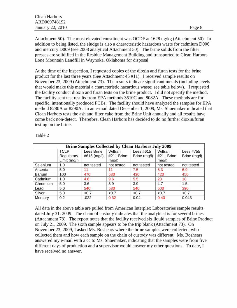
At the time of the inspection, I requested copies of the dioxin and furan tests for the brine
product for the last three years (See Attachment 45 #11). I received sample results on
November 23, 2009 (Attachment 73). The results indicate significant metals (including levels
that would make this material a characteristic hazardous waste; see table below). I requested
the facility conduct dioxin and furan tests on the brine product. I did not specify the method.
The facility sent test results from EPA methods 3510C and 8082A. These methods are for
specific, intentionally produced PCBs. The facility should have analyzed the samples for EPA
method 8280A or 8290A. In an e-mail dated December 1, 2009, Ms. Shoemaker indicated that
Clean Harbors tests the ash and filter cake from the Brine Unit annually and all results have
come back non-detect. Therefore, Clean Harbors has decided to do no further dioxin/furan
testing on the brine.
Table 2
Brine Samples Collected by Clean Harbors July 2009 TCLP
Regulatory Limit (mg/l)
Lees Brine #615 (mg/l)
Wiltran #211 Brine (mg/l)
Lees #615 Brine (mg/l)
Wiltran #211 Brine (mg/l)
Lees #755 Brine (mg/l)
Selenium 1.0 not tested not tested not tested not tested not tested
Arsenic 5.0 11 11 7.5 5.3 6.9
Barium 100 470 530 430 420 450
Cadmium 1.0 4.6 9.6 5.5 23 18
Chromium 5.0 3.6 3.9 3.9 4.7 1.5
Lead 5.0 540 530 540 500 390
Silver 5.0 <0.7 <0.7 <0.7 <0.7 <0.7
Mercury 0.2 .022 0.32 0.04 0.43 0.043
All data in the above table are pulled from American Interplex Laboratories sample results
dated July 31, 2009. The chain of custody indicates that the analytical is for several brines
(Attachment 73). The report notes that the facility received six liquid samples of Brine Product
on July 21, 2009. The sixth sample appears to be the trip blank (Attachment 73). On
November 23, 2009, I asked Ms. Boshears where the brine samples were collected, who
collected them and how each sample on the chain of custody was different. Ms. Boshears
answered my e-mail with a cc to Ms. Shoemaker, indicating that the samples were from five
different days of production and a supervisor would answer my other questions. To date, I
have received no answer.
Clean Harbors
ARD069748192
January 22, 2010 Page 9
Former Brine Process
Prior to the installation of the brine plant, brine was concentrated using waste heat from
incineration. According to Mr. Shoemaker, the waste heat concentration system was scrapped
when the secondary combustion chamber (SCC) was added to comply with the new incinerator
MACT.
Groundwater contamination from former brine process
Between 1982 and 1987, brine from the incinerator was managed in an on-site surface
impoundment (approximately where Tank 576 now sits). That surface impoundment released
brine to groundwater. That brine contaminated groundwater (mixed with hydrocarbon
contaminated groundwater) is being recovered in on-site recovery wells R2 and R2a
(Attachment 47). Between 1988, when groundwater pumping to recover chloride began, and
2008 the facility recovered 208,489,526 gallons of groundwater contaminated with high
chloride contaminants (Attachment 47).
Following groundwater recovery, the brine, water and hydrocarbon mixture are separated in an
oil water separator (Tank 630; Photo 13 center). The hydrocarbon portion is then accumulated
in Tank 629 and the water/brine portion in Tank 628 (Photo 13). At the time of the inspection,
there were two openings in Tank 629. Mr. Kevin LeBlanc of EMS USA (the contractor that
conducts subpart BB monitoring at Clean Harbors) monitored both openings during the
inspection. The opening seen in Photo 11 had an emission concentration of 145,000 ppm
according to Mr. Leblanc. The opening seen in Photo 12 had an emission concentration of 238
ppm according to Mr. Leblanc. The recovered oil is fed to the waste fired boiler or the
secondary combustion chamber of the incinerator as a fuel according to an e-mail from Ms.
Shoemaker. The recovered brine is added back to the brine condenser loop with no further
treatment according to Mr. Shoemaker.
I did not attempt to make a regulatory determination on the recovered high chloride water, but
it may be a listed hazardous waste based on EPA’s contained in policy.
According to an e-mail received from Ms. Shoemaker, the surface impoundments that
discharged brine to groundwater began receiving brine in 1982 and closure began in 1987.
SCC Ash Tray
The Secondary Combustion Chamber (SCC) was described as an “afterburner” by
Mr. Scot Shoemaker. Gasses from both kilns enter the SCC after passing through cyclones
which remove most of the ash generated in the kilns (Attachment 1). Liquid waste and
secondary heating fuel (natural gas) are directly injected into the SCC.
During the inspection, I observed several small leaks from the SCC ash bin. The ash bin is
located at the base of the SCC unit. The ash bin is partially filled with water to keep the SCC
from drawing in ambient air. In addition to the small leaks, the ash bin discharged water
Clean Harbors
ARD069748192
January 22, 2010 Page 10
through a pipe to the loading dock where a roll off container was staged to accumulate the ash
from the ash bin (Photo 19). At the time of the inspection, the roll-off was labeled hazardous
waste, but not dated with the initial date of accumulation (Photo 19). At the time the photo
was taken, the ash bin contained more that 55 gallons of hazardous waste. According to Mr.
Michael Karp, the pipe discharges to the loading dock intermittently when the water level in
the ash bin is high and ash drops into the bin. Waste discharged to the loading dock flows
across the dock to a sump where it will be pumped back to the scrubber loop according to Mr.
Karp (Photos 20-24 and 71-73).
In addition to the overflow across the loading dock, liquids from the ash bin ash collection roll
off are pumped to a sump at the heat exchanger pad (Photos 88, 90). The liquids from the ash
bin will be pumped back to the condenser as part of the brine scrubbing loop according to
Mr. Karp. The ash is a listed hazardous waste carrying over 500 listings (Attachment 15).
General Container Labeling
Residue Management Building
Clean Harbors treats incinerator ash (along with some other wastes generated on-site) by
stabilization with cement kiln dust (CKD) in their Residue Management Building. Following
treatment, the stabilized ash (which is still a hazardous waste) is sent to Clean Harbors Lone
Mountain Landfill in Waynoka, Oklahoma. Stabilization (treatment) occurs in an in ground
tank (Photos 31 and 92). According to the facility’s Permit Module XV Section (F)(1) and
(F)(2). All doors and openings must be closed prior to unloading ash into the tanks in the
Residue Management Building. Additionally, all doors and openings must be closed prior to
treating waste in the Residue Management Building.
During the inspection, I noted that the door to the Residue Management Building was damaged
and could not be closed (Photo 42). The door was damaged on May 4, 2009 according to the
work order for repair (Attachment 27). According to the facility’s operating log loading,
unloading, and treatment of ash continued in the Residue Management Building after the door
was damaged and could not be shut. Attachment 28 shows the operating logs for ash loading
and unloading. According to Attachment 28, the facility treated approximately three million
pounds of listed hazardous waste while the door was broken and unable to close. In addition to
the broken door, I observed other holes in the Residue Management Building. Photos 32 and
43 show separate holes in the Residue Management Building. A repair tag on the hole seen in
Photo 43 notes “tin on east back side of mixing building rotted out. Needs repaired.” The tag
was dated 1/13/09 (Photo 44). It appears that the facility operated the Residue Management
Building for over four months with holes in the building. The facility was aware of the holes
as indicated by the repair tag.
In addition to the holes in the Residue Management Building, it appeared that there may be
some “drag out” of listed waste from the building to the southwest catchment area outside the
Residue Management Building.
Clean Harbors
ARD069748192
January 22, 2010 Page 11
Photo 34 shows potential drag out of ash from the Residue Management Building. Photo 88
shows sediment that may include listed waste from drag out in the southwest catchment area
outside the Residue Management Building. At the time of the inspection, the facility had no
measures in place to prevent drag out of hazardous waste. Furthermore, the facility only
checked accumulated stormwater for compliance with their NPDES requirements prior to
pumping it to one of their retention areas (in this case Retention Area 10). I am concerned that
the facility may be redistributing listed hazardous waste (incinerator ash) throughout the
facility.
Attachments 23 and 23b contain records of stormwater testing and pumping. On Attachments
23 and 23b the area around the Residue Management Building is referred to as the “Box Lot”.
According to Ms. Shoemaker, the facility tests accumulated stormwater against the facility’s
NPDES outfall standards. If the stormwater meets the NPDES outfall requirements, it is
discharged to Retention Area 10. If not, it is captured and burned in the incinerator. NPDES
requirements for the facility are pH 6-9, chlorides less than or equal to 200 ppm and Total
Organic Carbon less than or equal to 200 ppm. None of these tests will show the presence or
absence of listed hazardous waste. Attachment 63 tracks a load of stormwater that was
collected and processed through the system.
According to Mr. Kuhn, the facility has changed their process since the first phase of the
inspection. Facility personnel now use compressed air to blow ash off tires and vehicles prior
to moving them from the Residue Management Building.
According to the facility’s permit, the Residue Management Building contains two hazardous
waste tanks (Tank 566 and Tank 564). The facility removed, partially closed, and paved over
Tank 564 (Photo 93). The closure for the tank began in February 2009 and consisted of
hydrowashing, removal of the inner shield, and sandblasting (Attachment 30). According to
Ms. Shoemaker, the facility did not take samples inside or outside the secondary containment
(see e-mail dated 9-22-09; Attachment 70). Module IV Section H requires closure to be
conducted according the Section I of the facility’s Part B permit application. According to Ms.
Shoemaker, Clean Harbors considers Tank 564 partially closed. At the closure of the facility,
the secondary containment, which has been paved over, will be sampled (see e-mail
Attachment 70).
The facility is using the term “partial closure” to cover incomplete closure of units at the
facility. “Partial Closure” as defined in 40 CFR 260.10 refers to a RCRA closed unit at an
operating facility. The tanks that Clean Harbors has not fully RCRA closed are fully RCRA
regulated.
Tank 566 was not labeled with the words “hazardous waste” during my first visit to the facility
in May (Photos 31 and 32). The tank was labeled on my second visit to the site in June (Photo
94).
Clean Harbors
ARD069748192
January 22, 2010 Page 12
TANKS
RCRA Subparts BB and CC
This commercial facility treats, stores and disposes of hazardous waste that contains at least
10% organics by weight and has a volatile organic content of greater than 500 (parts per
million by weight (ppmw). Therefore, the facility is subject to RCRA Subpart BB and CC.
Section D-2.g.A.2 of the facility’s permit application (Attachment 38) notes that the facility
manages diverse wastes, some of which are not subject to RCRA Subpart BB standards.
However, the facility has determined to manage all wastes and all waste systems coming in
contact with hazardous waste as if it were subject to Subpart BB. Furthermore, in section D-
2.g.B.3 of the permit application the facility states that all valves contacting waste with greater
than 10% organics are considered to be in “light liquid service” under RCRA Subpart BB.
Finally, in section D-2.g.B.4 the facility states that all pumps contacting waste with greater
than 10% organics are considered to be in “light liquid service” under RCRA Subpart BB
(Attachment 38).
Clean Harbors has designated all hazardous waste tanks at the facility “Level 2” tanks (Permit
application section D-2.g.B.2 page 35; Attachment 38). All applicable tank emissions at Clean
Harbors should be controlled by carbon filtration according to the facility’s permit application.
I have concerns about the facility’s carbon monitoring strategy which I discuss below in
relation to Tank 15.
Tanks 8-11
On May 19, 2009, I observed permitted hazardous waste Tanks 8-11 (See facility map
Attachment 66). I noted several potential emission sources from these tanks.
All four tanks (8-11) had open ended lines. The four tanks are manually gauged via 1.5”-2”
piping. In each case, one of the valves on the piping was left open and one was closed (Photos
11-14). At the time of the inspection each of these tanks contained hazardous waste
(Attachment 20). Upon my second visit to this tank farm on June 24, 2009, the open ended
lines were closed as required by Permit Module II (R)(1) – which references 264.1056 (a)(1).
In addition, tanks 8-11 are all vented through “P” traps (Photo 74). Mr. Shoemaker claimed in
an e-mail that the “P” traps were pressure relief devices that are redundant (see e-mail dated
10-2-09). Ms. Shoemaker noted that Clean Harbors planned to remove the P traps but did not
give a date.
In addition to the open ended line, Tank 9 had an opening approximately ¾” in diameter
(Photo 10). According to Mr. Wilhite, the opening resulted from the previous removal of a
level indicator. The opening appeared to penetrate to the interior of the tank. At the time of
the inspection, this tank contained 2,378 gallons of high BTU hazardous waste (Attachment
20). This opening was not routed to a control device as required by Permit Module II (R)(1) –
Clean Harbors
ARD069748192
January 22, 2010 Page 13
which references 264.1084 (g)(1)(ii). During my second visit to this location on June 24, 2009,
the hole was plugged and the level indicator was still visible at the top of the tank (Photo 79).
Return Visit Tank Inspection
On June 24, 2009, I returned to inspect the facility’s tanks. I was accompanied by several
Clean Harbors personnel and Kevin LeBlanc, Regional Operations Manager LDAR and
Analytical Division - EMS USA, (a Clean Harbors contractor for Subpart BB and CC
compliance). Mr. LeBlanc conducted Method 21 Leak Detection and Repair (LDAR)
monitoring in support of my inspection. The calibration log for the monitoring is included as
Attachment 70.
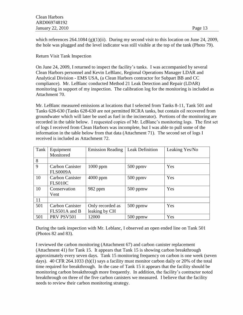
Mr. LeBlanc measured emissions at locations that I selected from Tanks 8-11, Tank 501 and
Tanks 628-630 (Tanks 628-630 are not permitted RCRA tanks, but contain oil recovered from
groundwater which will later be used as fuel in the incinerator). Portions of the monitoring are
recorded in the table below. I requested copies of Mr. LeBlanc’s monitoring logs. The first set
of logs I received from Clean Harbors was incomplete, but I was able to pull some of the
information in the table below from that data (Attachment 71). The second set of logs I
received is included as Attachment 72.
Tank Equipment
Monitored
Emission Reading Leak Definition Leaking Yes/No
8
9 Carbon Canister
FLS0009A
1000 ppm 500 ppmv Yes
10 Carbon Canister
FLS010C
4000 ppm 500 ppmv Yes
10 Conservation
Vent
982 ppm 500 ppmw Yes
11
501 Carbon Canister
FLS501A and B
Only recorded as
leaking by CH
500 ppmw Yes
501 PRV PSV501 12000 500 ppmw Yes
During the tank inspection with Mr. Leblanc, I observed an open ended line on Tank 501
(Photos 82 and 83).
I reviewed the carbon monitoring (Attachment 67) and carbon canister replacement
(Attachment 41) for Tank 15. It appears that Tank 15 is showing carbon breakthrough
approximately every seven days. Tank 15 monitoring frequency on carbon is one week (seven
days). 40 CFR 264.1033 (h)(1) says a facility must monitor carbon daily or 20% of the total
time required for breakthrough. In the case of Tank 15 it appears that the facility should be
monitoring carbon breakthrough more frequently. In addition, the facility’s contractor noted
breakthrough on three of the five carbon canisters we measured. I believe that the facility
needs to review their carbon monitoring strategy.
Clean Harbors
ARD069748192
January 22, 2010 Page 14
The facility uses “P” traps (an upside down “U” filled with water) to prevent emissions on
Tanks 8, 9, 10, 11, 501 and 545 (Photo 74). According to Ms. Shoemaker, the “P” traps are
emergency relief devices (See e-mail dated October 2, 2009), but they are redundant (phone
conversation January 12, 2010). Because the “P” traps on Tanks 8-11 are not needed as
emergency vents. I believe they should be regulated as open ended lines (40 CFR 264.1056
(a)(1)). Open ended lines require two closure devices. Clean Harbors should alter the “P”
traps in order to meet the requirements of 40 CFR 264.1056 (a)(1) or remove them. In an e-
mail dated October 2, 2009 Ms. Shoemaker indicated that the “P” traps on Tanks 8-11would be
removed, but would not give a scheduled date for removal when requested by e-mail and
phone (Phone conversation January 12, 2009).
During my inspection on May 21, 2009, I observed the “P” trap on Tank 545 (Photo 70). At
the time of the inspection, that trap had no water and therefore could allow VOC emissions.
Furthermore, the screw fitting that must be removed to check the water level or add water to
the “P” trap was so rusted that it could not be removed during the inspection. No other “P”
traps were observed during the initial inspection in May, 2009. In my experience, these “P”
traps are an unusual feature for hazardous waste tanks. Facility tank inspection logs
(Attachments 35, 60 and 61 for Tanks 501 and 545; and Attachment 39) do not explicitly
require monitoring of the traps. Instructions for Bulk Handling Personnel (Attachment 74) list
the traps as a required inspection area, but do not list the frequency of the inspections.
The facility has an in line grinder on a hazardous waste line at the facility’s “Day Tanks”. The
grinder was labeled “144 MTR250B” (Photo 41). Grinders are subject to RCRA subpart CC
and for the purpose of RCRA Subpart CC are regulated as Tanks (see RO 14392). According
to Ms. Shoemaker, all in line grinders at the facility have been removed (see e-mail 9/28/09).
Tank 8-11 Secondary Containment
I reviewed secondary containment documentation for Tanks 8-11 during my first week at the
facility. Ms. Shoemaker provided me with a copy of a stamped survey dated 3/18/93
(Attachment 5). I asked if the survey had been recently checked or if any engineering changes
had been made to the containment since 1993. Ms. Shoemaker volunteered to research the
question.
When I returned to the facility on June 24, 2009, I was provided with a new survey of the
secondary containment for tanks 8-11. The copy I have shows a surveyors stamp and is dated
6-23-09 (Attachment 64). This new survey showed the secondary containment to be minimally
large enough to contain the volume of the largest tank and the contents of a 25 year 24 hour
rainfall event. According to the survey the minimum elevation required to meet the
requirement was 232.58 feet and the minimum height of the retaining wall was 233.63 feet.
According to the survey, the HDPE liner on the southeast wall was 0.05 feet above the
minimum required height. At the time of the second inspection, I noted that the survey did not
appear to match the containment I observed. Photo 75 shows what appears to be the low point
of the containment (HDPE against the southeast concrete wall; center left). I estimated the
Clean Harbors
ARD069748192
January 22, 2010 Page 15
liner to be approximately two feet lower than the adjacent wall. However, the survey showed
the lower containment to be only 1.06 feet lower than the adjacent wall (Attachment 64). I
asked Mr. Shoemaker to clarify this. Mr. Shoemaker called the surveyor while in my presence
and verified that the survey was correct.
After leaving the facility I was still concerned about the height of the containment wall and I
sent an e-mail (Attachment 67). On 7-15-09 I received an e-mail from Ms. Shoemaker
(Attachment 68). This e-mail includes a message from Delbert Vanlandingham (I assume the
surveyor). Mr. Vanlandingham’s message notes that a shot of the southeast corner of the
containment was inadvertently missed when the drawing was “cleaned up for use” (see
Attachment 65 for detail of missed shot). Mr. Vanlandingham’s note lists the top of the liner
plate as 232.17 feet. This is 0.41 feet below the required height of 232.58 feet. The note
recommends that the liner be extended to 233.23 feet (Attachment 68).
On 8/18/09, I received an e-mail and photo from Ms. Shoemaker noting that the liner had been
extended (Attachment 69).
Secondary Containment for Used Oil Tanks
Photo 76 shows Tank 4. The tank is situated in a native clay and soil secondary containment.
40 CFR 279.54 (d) requires secondary containment for used oil tanks to include a floor that is
sufficiently impervious to used oil to prevent any used oil released from the tanks from
migrating or an equivalent containment system. During the inspection, Tank 4 contained
126,893 gallons of used oil according to an e-mail from Ms. Shoemaker.
General Secondary Containment Concerns
Hazardous waste storage tanks 1-4, 8-11, 501, and 545 all use HDPE liner systems for
secondary containment. Permit Module IV.C requires the facility to maintain the tank
secondary containment system. The facility’s permit application which is referenced by permit
condition Module IV.C notes that tank secondary containment must be:
Constructed of or lined with materials that are compatible with the wastes(s) to be placed in the tank system and must
have sufficient strength and thickness to prevent failure owing to pressure gradients (including static head and external hydrological forces), physical contact with the waste to which it is exposed, climatic conditions, and the stress of daily
operation (including stresses from nearby vehicular traffic).
The above text is from 264.193 (c)(1).
I noted several holes in the HDPE liners for Tanks 8, 9, 10, 11, and 545. I am concerned that
the HDPE liners are not able to withstand the “stress of daily operation”. For examples of
damaged liners see Photos 66, 67, 68 and 69 (at Tank 545), and Photos 77 and 78 (at Tanks 8-
11). I estimated one hole in the liner for Tank 545 to be approximately three feet long (Photos
66 and 67). In an inspection follow-up e-mail to Ms. Shoemaker, I asked about the holes in the
liner for Tank 8 that were noted in the facility’s tank inspection logs for the period 4/1/09-
5/21/09 (Attachment 39). Ms. Shoemaker responded that the work orders for repairing the
Clean Harbors
ARD069748192
January 22, 2010 Page 16
holes were issued on 3/30 and 5/19. Holes are noted in the liner at Tank 8 for 11 (eleven) days
during the 51 (fifty-one) day period I reviewed 4/1/09-5/21/09 (Attachment 39).
Attachment 57 contains a list of liner repairs from January 2008 to May 2009. In addition,
Attachment 57 contains the facility’s Standard Operating Procedure (SOP) for repairing liners.
Finally, some liner holes may have gone unnoticed. The original tank inspection protocol for
Tanks 501 and 545 required the vacuum truck driver to visit 21 sites, some separated by a
relatively large distance, vacuum any accumulated water and make a checkmark on the
inspection log (Attachment 60). On days when no liquids were vacuumed up the driver
completed his task in approximately one hour (see 1/4/09 in Attachment 60 for an example).
On days where material was removed from containment the task took the driver approximately
2-hours (see 1/1/09 in Attachment 60 for an example). When I visited Tank 545 on 5/20/09 I
noted several holes in the liner (I estimated one hole to be approximately three (3) feet long
(Photo 68). These holes were not noted in the tank inspection logs (Attachment 60). In
addition when I observed the “P” trap on Tank 545, I noted that it contained no water and
therefore was not being operated in a manner to prevent air releases to the environment. In
addition, the cap that must be removed in order to check the water level in the “P” trap or add
water to the “P” trap was so rusted from disuse it could not be removed by maintenance
personnel with tools during the inspection (see Photo 70).
Secondary Containment for Ancillary Equipment
The facility manages hazardous waste in tanks. The waste is transferred between tanks via
single wall piping that is not pressurized and is not equipped with automatic shutoff systems.
Most of the piping is above ground, and according to Ms. Shoemaker, is inspected daily. Some
of the above ground piping is equipped with screwed flanges, joints and valves. Secondary
containment for ancillary equipment is required by 264.193 (f) and Permit Module IV C.
Attachment 33 shows a review of piping produced by Teris as a result of an Agreed Order with
ADEQ relating to a release from abandoned piping at the facility. Attachment 58 shows
diagrams of the hazardous waste lines feeding and emptying Tank 501. Some of these lines
had non exempt fasteners or valves and were not equipped with secondary containment as
described below.
Photo 46 shows a valve on a hazardous waste line used to transfer waste from the rail loading
and unloading rack to Tank 501. The valve is over dirt, rock and uncurbed concrete and had
no secondary containment at the time of the inspection (Photo 47). The valve is identified as a
ball valve on the BB equipment list in Attachment 58. According to the permit, Tank 501 can
manage all hazardous waste codes included in the facility’s Part A application. At the time of
the inspection, Tank 501 contained 45,949 gallons of high BTU waste (Attachment 20).
Photo 49 shows two valves with no secondary containment. The valves are on piping from the
rail rack to Tank 501. One valve is not labeled, the second is listed as 144 VLV 501Z. The
valve is shown on a drawing in Attachment 58, but I could not locate its descriptor
Clean Harbors
ARD069748192
January 22, 2010 Page 17
(Attachment 58). Photo 50 shows that the two valves previously mentioned plus a third seen in
Photo 51 have no secondary containment. These valves are on the hazardous waste line that
transfers waste between the rail rack and Tank 501.
Photo 51 shows an unlabeled valve over secondary containment. This valve is also an open
ended line. The line ends in an open air compressor quick connect.
Photo 52 shows five valves on hazardous waste lines used to transfer waste between the day
tanks and Tank 501. Photo 53 shows that the five valves seen in Photo 52 do not have
secondary containment. Photos 54-57 show close-ups of the five valves.
Photo 59 shows a valve with no secondary containment used to transfer waste from the rail car
unloading and loading area to the “day tanks”.
Photo 60 shows a valve with no secondary containment used to transfer waste from the rail car
unloading and loading area to the “day tanks”.
Photo 61 shows a valve with no secondary containment used to transfer waste from the rail
rack to the “day tanks”.
Photo 63 shows a valve with no secondary containment used to transfer waste from the rail
rack to the “day tanks”.
Photo 64 shows the area under the valves seen in Photos 61-63.
Photo 35 shows four screw fittings on the hazardous waste line used to transfer waste to the
“day tanks”. A drawing of Lines 121 and 124 is included as Attachment 62.
Photo 36 shows a valve on hazardous waste line 124 that is has no secondary containment.
Photo 37 shows a valve on hazardous waste line 124 that is has no secondary containment.
Photo 38 shows a valve on hazardous waste line 124 that is has no secondary containment.
Photo 39 shows a valve on hazardous waste line 106 DWG 014 that is has no secondary
containment.
Photo 40 shows the labels on the hazardous waste lines attached to the valves and screw
fittings seen in Photos 35-38.
In summary, I observed approximately seventeen (17) ancillary equipment valves with no
secondary containment: Photo 46, Photo 49 (two valves), Photo 51, Photo 52 (five valves),
Photo 59, Photo 60, Photo 61, Photo 63, Photo 36, Photo 37, Photo 38, Photo 39 and four
screw fittings with no secondary containment (Photo 35).
Clean Harbors
ARD069748192
January 22, 2010 Page 18
Tank 501
Kevin LeBlanc, Regional Operations Manager LDAR and Analytical Division - EMS USA, (a
contractor for Subpart BB and CC compliance with Clean harbors) measured emissions from
the carbon canisters at this Tank 501 (144 FLS501B) at 9503 ppm, the top conservation vent at
12,000 ppm and the bottom conservation vent at 545 ppm. The leak definition for these pieces
of equipment is 500 ppm.
Open Ended Lines
Tanks 8-11 and 501 and 545 all had open ended lines during the inspection.
PROCESS TOUR
According to the facility’s final permit dated March 21, 2008, Clean Harbors manages
hazardous wastes in the following locations:
Container Storage for Hazardous Waste
Warehouse 204: This unit is a roofed, partially walled structure located west of the incinerator
complex measuring over 447 feet by 195 feet. The unit has reinforced
concrete floors and curbs. The concrete floors are coated (Carboline Phenolene 305 or
equivalent) making the concrete impervious to contain potential leaks or spills until
detected and removed. Warehouse 204 employs a modular steel racking system to allow
individual pallets of drummed waste to be accessed without disturbing other pallets.
This minimizes double handling of pallets once a pallet is retrieved for treatment, thus
improving efficiency and safety. In addition, the steel modular system negates a
pallet from being immediately placed (stacked) on top of other pallets.
Module III (M)(11)(d)(1) of the facility's permit states "Incoming truckloads of containers shall
be single height in “Area D” while awaiting analytical fingerprint verification of contents." I
noted double stacked 30 gallon fiber drums in "Area D" of 204 warehouse (Photo 4).
Containers in this area have not had the fingerprint test that is given to most incoming wastes.
These containers were wrapped during the inspection -- making them "one unit" and in
compliance with their permit.
During the inspection, I noted what appeared to be a crack in containment on the floor of 204
Warehouse (Photos 5 and 6). Module III (M)(4) of the facility's permit states "all flooring
including curbing shall be maintained to prevent cracks and gaps..." In addition, Permit
Module III (A)(1) notes that Warehouse 204 has concrete floors that are "coated (Carboline
Phenolene 305 or equivalent) making the concrete impervious to spills..." It appears that the
coating in this area may be damaged. Ms. Shoemaker indicated that the crack was at the
surface only and the coating was intact. I could not discern this by visual observation.
Clean Harbors
ARD069748192
January 22, 2010 Page 19
During the inspection I noted a cubic yard container labeled Hazardous Waste Trash. The
container contained more than 55-gallons of waste and was not dated (Photos 8 and 9). The
container was located on the ramp between the 204 Warehouse and the fork lift charging area.
No more than 55 gallons of hazardous waste may be accumulated in satellite accumulation
without being dated.
The facility accumulates Lab Retain Samples in 204 Warehouse (Photo 7). Facility internal
protocol requires that these samples be held for 14 days after analysis of the sample. Based on
interviews with lab personnel - the facility puts incompatible wastes in the same container.
Lab personnel take a small sample from a small jar as received, conduct their analysis, place
the jar back in a box and then put the boxes in these containers. They do not segregate the
boxes or jars by hazard class. Permit Module III (K)(1) states that "The Permittee shall not
place incompatible wastes, or incompatible wastes and materials in the same container unless
the procedures in Regulation No. 23 264.17(b) are followed." The facility did not document
compliance with 264.17(b). The facility began segregating this waste during the inspection.
Oxidizer Storage Vaults: The Permittee is allowed to have up to four (4) individual Detached
Reactive Storage (DRS) buildings designated for oxidizer wastes. Each DRS is an engineered
modular steel storage building measuring 64 feet, 11 inches by 11 feet, 6 inches. Floors are
grated with ample secondary containment volume capacity underneath. These four DRS units
are designated as DRS Building A, DRS Building B, DRS Building C, and DRS Building D.
Water Reactive Storage Vaults: The Permittee is allowed to have up to six (6) individual
Detached Reactive Storage (DRS) buildings designated for water reactive wastes. Each
DRS is an engineered modular steel storage building measuring 64 feet, 9 inches by 24 feet, 1
inch. Floors are grated with ample secondary containment volume capacity
underneath. These four DRS units are designated as DRS Building E, DRS Building F, DRS
Building G, DRS Building H, DRS Building I, and DRS Building J.
Compressed Gas Container Storage
Compressed Gas Storage Areas #1 and #2: The Permittee is allowed two (2) individual areas
designated to store compressed gas cylinders. Area #1 is tin roofed, constructed with concrete
floors and curbing measuring 47 feet, 5.5 inches by 16 feet, 3 inches. Area #2 is tin 1 Module
III roofed with a concrete floor, but without curbing, measuring 42 feet by 23 feet. These units
are not equipped with secondary containment since the stored materials are gasses at
atmospheric temperatures and pressures.
Analytical Lab
I toured the analytical lab with Ms. Shoemaker, Ms. Wilson, Ms. Duke, and Ms. Boshears. I
observed two areas of concern. First, the facility was satellite accumulating lab generated
wastes two times. The initial accumulation was under a fume hood (Photo 1) and the second
accumulation was in nearby drums (Photo 2). At the time Photo 2 was taken the drums
contained hazardous waste, but were not dated. I suggested that the facility make the drum
Clean Harbors
ARD069748192
January 22, 2010 Page 20
accumulation less than 90 day storage. Second, I noted one instance where a container holding
hazardous waste was not kept closed (Photo 3).
Baghouse Dust Collection area
During the inspection, I observed the baghouse dust collection area. The baghouse dust drops
from the baghouses into three containers approximately 250 gallons each. At the time of the
inspection, the containers were not labeled with the words “hazardous waste” and were not
dated. Because the containers were in use I could not determine the volume of waste in the
containers at the time of the inspection. According to Mr. Kuhn, Clean Harbors does not
consider this waste to be generated until the containers are removed from the unit.
Brine unit “finishing box” not dated (Photo 29).
Tank 576 is partially closed. This tank formerly managed the listed brine that is now
reclaimed in brine treatment. The facility lists these tanks as “active” in their current permit
(Attachment 38). ADEQ requested that the facility close Tank 576 or repair its secondary
containment in a letter dated March 2, 2007 (Attachment 56). This tank previously handled
listed hazardous waste (spent brine). The tank has not been RCRA closed and therefore any
material (rainwater for example) contacting the tank could be considered listed hazardous
waste based on the “contained in” policy. Because the rainwater may have contacted listed
waste the facility needs to show that the resulting rainwater does not contain listed wastes. The
tank has numerous holes in the floor and appears to be in poor condition (Photos 95-98). In
addition, the side of the tank has been cut (Photo 95). Runoff from the tank may go to several
areas including Retention Area 10 according to Mr. Boshears. Additionally, this tank is listed
as “active” therefore the facility should be doing all monitoring required by the permit
(maintaining an 18 inch freeboard for example). Because of the holes in the tank and the
access way cut out, the facility cannot maintain an 18 inch freeboard as required by Permit
Module IV Section M. Special Condition 1. I suggest that the facility repair or close this tank.
AREAS OF CONCERN
Areas of Concern noted during the inspection
1 Permit Module I (A) and Regulation No. 23 270.1 – Permit Required
During the inspection, I noted that the facility disposes of spent brine by reclamation
followed by sale to end users who place the brine onto or into the land. Spent materials
that are reclaimed are solid wastes. Commercial chemical products are solid waste
when applied to the land.
2 Permit Module XV Section (F)(1) and (F)(2) – Residue Management Building Special
Conditions
Clean Harbors
ARD069748192
January 22, 2010 Page 21
Permit Module 15 special conditions require that all openings and doors must be kept
closed when unloading and treating ash in the Residue Management Building. The
door to the Residue Management building was damaged on 5/4/09. Ash loading,
unloading and treatment continued after that time. In addition, two separate holes were
noted in the building. One of the holes was marked with a need to repair tag dated
January 13, 2009. The holes in the building were repaired prior to my second visit to
the facility and the door was being repaired at that time.
3 Permit Module II (R)(1) and 40 CFR 264. 1056 (a)(1) - Open ended lines
I observed open ended lines in light liquid hazardous waste service in several areas:
a) Tanks 8-11 each had one open ended line at the manual gauging stations during the
initial inspection. The open ended lines were closed on my second visit.
b) Tank 501 had one open ended line at the no longer used gauging station.
c) The hazardous waste line leading to/from Tank 501 had one open ended line at an air
compressor connection port.
I requested that the facility close all open ended lines.
4 Permit Module II (R)(1) and Regulation 23 264. 1087 (c)(3)(i) (references 264.1033 h)
The facility currently monitors the carbon on Tank 15 for breakthrough weekly.
Records indicate that breakthrough for the carbon on this tank is approximately ten
days. 264.1033 (h)(1) says they must monitor daily or 20% of the total time required
for breakthrough i.e. two days. In addition, the facility’s contractor noted breakthrough
on three of the five carbon canisters we measured. I requested that the facility review
their entire carbon monitoring strategy.
5 Permit Module II (R)(1) and Regulation 23 264.1056 (a)(1)
The facility uses “P” traps (an upside down “U” filled with water) to prevent emissions
on Tanks 8-11 (Photo 74) and Tanks 501 and 545. According to Ms. Shoemaker, the P
traps are emergency relief devices (See e-mail dated October 2, 2009). Ms. Shoemaker
also indicated that new conservation vents were added to Tanks 8-11. Because the “P”
traps on Tanks 8-11 are no longer needed as emergency vents. I believe they should be
regulated as open ended lines. Open ended lines require two closure devices. Clean
Harbors should alter the “P” traps in order to meet the requirements of Regulation 23
264.1056 (a)(1) or remove them.
6 Permit Module II (R)(1) and Regulation 23 264.1033 (l)(3) – Standards for Closed Vent
Systems
Clean Harbors
ARD069748192
January 22, 2010 Page 22
On May 19, 2009, I toured the Day Tank area. I noted and Clean Harbors personnel
confirmed a strong VOC odor in the tank farm. The facility did not follow that leak
detection with method 21 monitoring within five days
7 Permit Module Permit Module IV. C. and Regulation No 23 264.193 (c)(1) –
Secondary Containment Systems.
During the inspection, I noted numerous holes in HDPE secondary containment for
Tanks 8, 9, 10, 11, 501 and 545. It appears that the liners may not be of sufficient
strength to withstand the stresses of daily operation at the facility. I requested that the
facility review their liner choices.
8 Permit Module IV. C. and Regulation No 23 264.193 (f) – Secondary Containment for
Ancillary Equipment
During the inspection, I noted non-exempt ancillary equipment with no secondary
containment at approximately twenty-one locations. I requested that the facility review
and update the secondary containment for their tank’s ancillary equipment.
9 Permit Module IV. M. Special Condition 1. – Freeboard for Tank 576
During the inspection, I noted that the side wall of “active” Tank 576 had been cut. It
appeared that the cut extended to approximately 10 inches from the floor. Therefore,
the facility is no longer able to maintain the 18 inch freeboard as required by the permit
special condition. I suggested that the facility RCRA close or repair the tank.
10 Permit Module IV. F. Tank Inspection Schedules
During the inspection, I noted that the facility ceased inspections of Tank 576 and Tank
564 after “partially closing” them. In order to escape RCRA regulations, the tanks
must be fully RCRA closed. I requested that the facility RCRA close Tanks 576 and
564.
AOC issued and Resolved during the Current Inspection
1 40 CFR 262.34 (c)(1) – Satellite Accumulation
During the inspection, I noted that satellite accumulated waste in the analytical lab was
not kept closed. I requested that the facility move the waste in question to a container
that had a closure device. The facility disposed of this container during the inspection
and replaced the container with a new style of container.
2 Regulation 23 262.34 (a)(2) – Accumulation in Containers

Clean Harbors
ARD069748192
January 22, 2010 Page 23
During the inspection, I noted several areas where the facility accumulated more than
55-gallons of hazardous waste in containers without dating those containers.
a) I observed drums containing hazardous waste in the analytical lab. Two drums that
were identified by lab personnel as receiving waste that had been previously satellite
accumulated were observed in the lab. The drums both contained hazardous waste and
were not dated. The drums were dated before the inspection ended.
b) I observed baghouse dust collectors with a capacity of approximately 250 gallons of
baghouse dust. These were not dated at the time of the inspection. According to Ms.
Shoemaker, these containers are now labeled hazardous waste and dated.
c) I noted that the brine unit generates a sludge which is a listed hazardous waste and
which is accumulated in a “finishing box”. At the time of the inspection, the “finishing
box” contained more than 55-gallons of hazardous waste and was not dated. The
container was dated during the inspection.
d) I observed a roll-off receiving ash and contact cooling water (brine) from the SCC
ash tray dragout. The roll-off was not closed because it was receiving waste at this
time. This roll-off was labeled Hazardous Waste but not dated. The container was
dated during the inspection.
e) I noted a cubic yard container labeled “Hazardous Waste Trash” located on the ramp
between the 204 Warehouse and the fork lift charging area. The container contained
more than 55-gallons of waste and was not dated. This area was identified as a less
than 90 day storage area by Ms. Shoemaker.
3 Permit Module III (M)(11)(d)(1) – Storage in Containers
Module III (M)(11)(d)(1) of the facility's permit states "Incoming truckloads of
containers shall be single height in Area D while awaiting analytical fingerprint
verification of contents." I noted double stacked 30 gallon fiber drums in "Area D" of
204 warehouse. Containers in this area have not had the fingerprint test. These
containers were wrapped during the inspection -- making them "one unit" and in
compliance with their permit.
4 Permit Module II (R)(1) and Regulation 23 264.1084 (d) – Emission Standards
During the inspection, I noted a leaking in-line grinder on a hazardous waste line at the
facility’s “Day Tanks”. Grinders are subject to RCRA subpart CC and for the purpose
of RCRA Subpart CC are regulated as Tanks. According to Ms. Shoemaker, all in line
grinders at the facility have been removed.
Clean Harbors
ARD069748192
January 22, 2010 Page 24
5 Permit Module II (R)(1) and Regulation 23 264.1084 (g)(1)(ii)
For tanks subject to RCRA Subpart CC each opening in the tank must be equipped with
a closure device or controlled. Tanks 9, and 545 had openings during the inspection.
During the second visit, I observed Tank 9 to be closed. The facility did maintenance
on this tank and the “P” trap is now filled with water.
6 Permit Module III (K)(1) and Regulation No. 23 264.17(b)
During the inspection, I noted that the facility manages “Lab Retain Samples”. These
samples must be held by the facility for 14 days after analysis of the sample. Based on
interviews with lab personnel, the facility puts incompatible wastes in the same
container. Lab personnel take a small sample from a small jar as received, do their
analytical, place the jar back in a box and then put the boxes in the containers seen in
Photo 14. They do not segregate the boxes or jars by hazard class. Permit Module III
(K)(1) states that "The permittee shall not place incompatible wastes, or incompatible
wastes and materials in the same container unless the procedures in Regulation No. 23
264.17(b) are followed." The facility did not document compliance with 264.17(b).
The facility began segregating this waste during the inspection.
7 Permit Module IV. C. and Regulation No 23 264.193 (e)(1) – Secondary Containment
During the inspection, I noted that secondary containment for Tanks 8, 9, 10, and 11
was inadequate to contain the volume of the largest tank plus a 25 year, 24 hour rainfall
event. The secondary containment was expanded during the inspection.
8 Permit Module IV F. 3. and Regulation No 23 264.195 (b) – Inspection of Secondary
Containment
During the inspection, I noted that the inspection protocol for the secondary
containment for Tanks 501 and 545 was inadequate to detect: holes in the liners or
malfunctioning control devices. I requested that the facility change their inspection
protocol. During the inspection, Mr. Kuhn provided me with a new electronic
inspection log and new protocol for inspecting these tanks.
OTHER AREAS OF CONCERN
1. Apparent crack in containment on floor of 204 Warehouse. Module III (M)(4) of the
facility's permit states "all flooring including curbing shall be maintained to prevent
cracks and gaps..." In addition, Permit Module III (A)(1) notes that Warehouse 204 has
concrete floors that are "coated (Carboline Phenolene 305 or equivalent) making the
concrete impervious to spills..." It appears that the coating in this area is damaged.
2. Potential drag out of listed waste from the Residue Management Building. At the time
of the inspection, the facility had no obvious means to prevent dragging listed waste
Clean Harbors
ARD069748192
January 22, 2010 Page 25
from the Residue Management Building to the containment area outside. From there
the listed waste could potentially be pumped to Retention Area 10 making it a RCRA
regulated surface impoundment. During my second visit to the site, new procedures
were implemented to prevent drag out. Specifically, the facility began using
compressed air to remove ash from truck tires and elsewhere on the trucks prior to
leaving the Residue Management Building.
3. Tank 564 in the Residue Management Building was partially closed and paved over.
No sampling of the secondary containment was done to determine if a release had
occurred from the tank. Module IV section H requires closure to be conducted
according the Section I of the facility’s part B permit application. According to Ms.
Shoemaker, Clean Harbors considers Tank 564 partially closed. When the tank is fully
closed at closure of the facility, the secondary containment, which has been paved over,
will be sampled. I am concerned about paving over potential contamination without
first sampling it.
4 Significant VOC emissions from the brine and recovered oil storage tanks (Tanks 628-
630). The tanks are not permitted RCRA tanks, but contain oil recovered from
groundwater which will later be used as make-up fuel in the incinerator. Two openings
in the tanks were monitored by a Clean Harbors contractor during the inspection. One
opening was emitting 145,000 ppm VOCs according to the monitoring. The second
opening was emitting VOCs at a concentration of 238 ppm. I requested that the facility
close the openings on these tanks.
5. During the inspection, the facility’s contractor measured five conservation vents. He
found leaks at two of those five. I requested that the facility attempt to ensure that their
pollution control equipment is functioning properly.
6. Secondary containment for used oil tanks. Tank 4, a used oil tank is situated in a native
clay and soil secondary containment. 40 CFR 279.54 (d) requires secondary
containment for used oil tanks to include a floor that is sufficiently impervious to used
oil to prevent any used oil released from the tanks from migrating. I requested that the
facility ensure that the clay liner is sufficiently impervious to used oil to prevent any
releases from migrating.
7. Clean Harbors is required to have financial assurance by permit provision Module II Q.
During the inspection I noted that the financial assurance the facility carried had a one
million dollar deductible (Attachment 43). This area of concern was also noted
independently by ADEQ and they took enforcement action.
8. Tank 576 previously contained a listed waste (spent brine). The tank has not been
RCRA closed. In addition, an access door has been cut into the side of the tank.
Runoff from the tank may go to several areas including Retention Area 10. Rainwater
from this tank may “contain” listed hazardous waste. I suggested that the facility
RCRA close or repair this tank.
Clean Harbors
ARD069748192
January 22, 2010 Page 26
ATTACHMENTS
1. Audit book designed for customers including the block flow diagram used by Mr. Scot
Shoemeaker to describe process.
2. P&ID for Incineration and Brine Recovery
3. NPDES Permit Application (electronic)
4. NMP internal sampling and manifest
5. Secondary containment calculations for Tanks 1-11 (This is the first version received
from Clean Harbors for the second version see Attachment 64 and for the third version
see Attachment 65)
6. Manifest from NMP generator
7. Original waste profile for NMP
8. ADEQ water permit with block flow diagram from water permit application
9. ENSCO explanation for why brine is exempt.
10. 2008 Annual report (on CD)
11. SOP for putting sample containers in 30 gallon drums in labs
12. SOP for secondary containment repairs on HDPE liners (See Attachment 57)
13. Volume of partially treated brine stored on-site in Baker Boxes and length of storage
14. WWTP sludge profile showing F listings
15. SCC ash profile
16. Ash profile for ash in residue management prior to treatment
17. SOP for pumping brine off SCC ash rolloff
18. List of all <90 day areas including copies of last 4 weekly inspection logs
19. SOP for secondary containment repairs on concrete
20. Facility description of volume and material in tanks at the time of the inspection.
21. Recent failed water sample from outside Residue Management Building
22. SOP for management of Box Lot wastewater
23. Water analysis for water collected on pad outside Residue Management Building
24. Manifest and LDR for Brine Filter Cake
25. SOP for management of water in SCC Ash Drag (See Attachment 17)
26. Contact list of people I interviewed during the inspection
27. Work order to repair broken door at Residue Management Building (door broken
5/4/09)
28. Operating logs for mixing, loading and unloading in the Residue Management Building
(showing that work occurred while the door was broken).
29. Closure and decontamination documentation for Tank 576 (See Attachment 54).
30. Tank 564 closure information
31. Waste management record for failed Residue Box Lot #2 wastewater (stormwater
collected outside the Residue Management Building; this document shows that the
wastewater was placed into hazardous waste tanks)
32. Environmental Department Org Chart
33. CAO piping report
34. Work order to repair liner on Tank 545 (sphere tank)
35. Daily inspections for Tank 545, 501, and other areas
Clean Harbors
ARD069748192
January 22, 2010 Page 27
36. Vapor pressure of waste in all tanks – the highest was 1.12 PSIA in Day Feed Tank
609; maximum allowed by permit is 1.60 PSIA
37. Specific Gravity for waste in Tanks 501 and 545 (501 is limited by permit to <1.26 and
545 is limited by permit to < 1.19)
38. Electronic version of the facility’s hazardous waste permit and permit application
39. Tank inspections 4-1-09 to 5-21-09
40. Selected subpart BB monitoring data for valves observed without secondary
containment during site tour
41. Work orders for all tanks from January 09 to May 09
42. Interim Closing Conference attendees
43. Financial Assurance (note this policy has a one million dollar deductible)
44. Disposal Records for Guzzler waste noted in Attachment 28 on 5-13-09
45. EPA Follow-up Questions
46. Characterization of WWTP sludge showing F listings
47. Description of high chloride groundwater wells and high chloride water management
48. Brine Recovery Diagram
49. Letters from brine end users
50. Brine sludge test results including dioxin test 2006-2008
51. Brine product analytical results including dioxin test (Clean Harbors has refused to do
this test)
51b. Brine product batch quality control log sheets
52. Most recent annual tank thickness testing
53. Hazardous Waste determination for wastes in Tanks 1-3
54. Analytical showing clean closure in Tank 576 (Tank 576 has not been closed, but has
been ordered to if the facility decides to no longer use it see Attachment 56)
55. North ditch analytical (if chloride < or = to 200 ppm then the water is discharged to
Retention Area 10)
56. Tank 575 closure info
57. Liner repair information (includes SOP)
58. Tank 501 subpart BB information on hazardous waste line
59. Analytical done on sumps prior to pumping to retention areas
60. Tank inspections for Tank 501 and 545
61. New tank inspection log
62. Line 121 and 124 description
63. Tracking guzzler and vacuum truck through system
64. Second Version of Secondary Containment Calculation Tanks 1-11
65. Third Version of Secondary Containment Calculation Tanks 1-11
66. Facility Map
67. e-mail requesting clarification of secondary containment volume
68. Clean Harbors response to e-mail requesting clarification of containment volume
69. Clean Harbors e-mail showing repaired liner
70. Calibration sheet for LDAR contractor
71. First set of LDAR data received from Clean Harbors and e-mail
72. Second set of LDAR data received from Clean Harbors and e-mail
73. Brine Product Sample Results
Clean Harbors
ARD069748192
January 22, 2010 Page 28
74. e-mail containing Subpart CC information from the facility’s permit, a statement that
the initial carbon canister performance test was done, instructions for the P trap
monitoring, and the new electronic checklist instructions.
75. Subpart CC carbon monitoring showing repeated carbon failures.
76. Some e-mail traffic between EPA and Clean Harbors
Note e-mails between Clean Harbors and EPA are stored as “Records”