Embed Size (px)
Citation preview


SIDEPLATE FOR SDS/2 USER GUIDE
PAGE 1© 2018 SIDEPLATE AND SDS/2
Please make sure to read the SIDEPLATE FOR SDS/2 INSTALLATION INSTRUCTIONS first. After following the instructions for installing SDS/2 v2016.25/v2017.16 or newer and the SidePlate for SDS/2 plugins, you are ready to start using the SidePlate plugins.
NOTE: YOU WILL NEED TO CONTACT SIDEPLATE FOR THE PROJECT XML FILE CONTAINING THE SIDEPLATE CONNECTIONS.
SETUPAfter receiving the SidePlate XML file, you will need to save the file in a location accessible to anyone running the SDS/2 project. We suggest creating a new folder inside the job called SidePlate and then placing the SidePlate XML file inside.
Next, you will need to set up your SDS/2 project so it is linked to the SidePlate XML file. To do this:
1. Select Job or Fabricator Options from the SDS/2 Main Menu.2. Under the Job Setup tab, select Component, as shown in Figure 1.3. Select SidePlate from the list and hit OK.4. Once the SidePlate Setup screen appears, select Browse.5. Locate the SidePlate XML file and hit Open. The file path will then appear.6. Select the appropriate bolt, angle, plate grades as specified in the contract documents.7. (Optional) To use TC bolts for the project, check the “Default TC for Bolts” option.6. Hit OK.
By following these instructions, your SDS/2 project is now linked to the SidePlate XML file.
ADDING ICONS TO THE TOOLBARYou will want to add both the SidePlate Markup Tool and SidePlate Import icons to your Modeling toolbar. To do this:
1. While in Modeling, from the Options pull-down menu, select Toolbar Configuration.2. Select Model -- Parametric for the Command Group, as shown in Figure 2.3. Drag and drop the SidePlate Markup Tool icon on to your toolbar.4. Drag and drop the SidePlate Import on to your toolbar.5. Hit OK.6. The Save Configuration File screen will appear, asking you to save the toolbar. By default, the current toolbar name will be listed. You can either hit OK, which will save as the same name, or change the name and hit OK.
a. If you leave the same name, you will need to hit Yes to overwrite the file.b. If you create a new toolbar file, you will need to specify that in User Options, under Configuration Files.
Figure 1: SDS/2 Setup Job or Fabricator Options
Figure 2: Toolbar Configuration
SIDEPLATE FOR SDS/2 USER GUIDE
PAGE 2© 2018 SIDEPLATE AND SDS/2
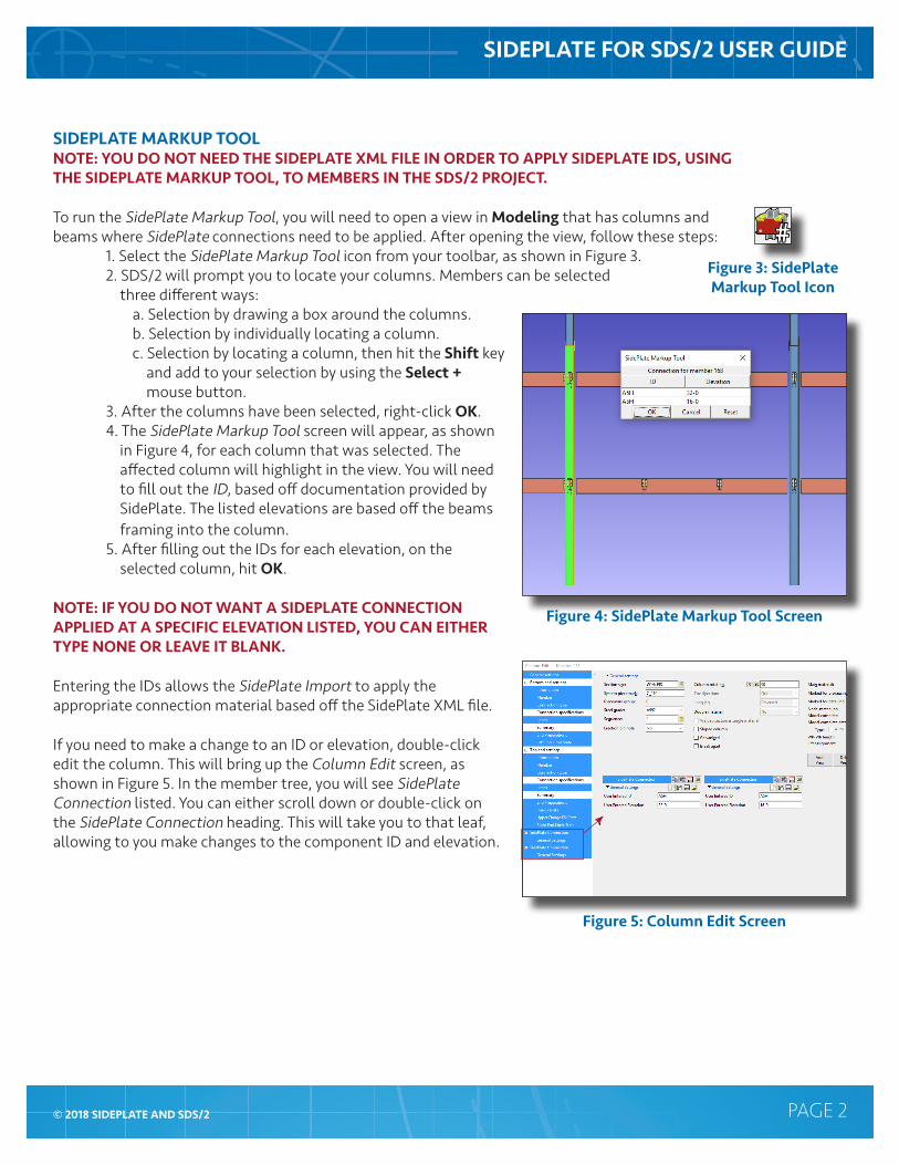
SIDEPLATE MARKUP TOOLNOTE: YOU DO NOT NEED THE SIDEPLATE XML FILE IN ORDER TO APPLY SIDEPLATE IDS, USING THE SIDEPLATE MARKUP TOOL, TO MEMBERS IN THE SDS/2 PROJECT.
To run the SidePlate Markup Tool, you will need to open a view in Modeling that has columns and beams where SidePlate connections need to be applied. After opening the view, follow these steps:
1. Select the SidePlate Markup Tool icon from your toolbar, as shown in Figure 3.2. SDS/2 will prompt you to locate your columns. Members can be selected three different ways:
a. Selection by drawing a box around the columns.b. Selection by individually locating a column.c. Selection by locating a column, then hit the Shift key and add to your selection by using the Select + mouse button.
3. After the columns have been selected, right-click OK.4. The SidePlate Markup Tool screen will appear, as shown in Figure 4, for each column that was selected. The affected column will highlight in the view. You will need to fill out the ID, based off documentation provided by SidePlate. The listed elevations are based off the beams framing into the column. 5. After filling out the IDs for each elevation, on the selected column, hit OK.
NOTE: IF YOU DO NOT WANT A SIDEPLATE CONNECTION APPLIED AT A SPECIFIC ELEVATION LISTED, YOU CAN EITHER TYPE NONE OR LEAVE IT BLANK.
Entering the IDs allows the SidePlate Import to apply the appropriate connection material based off the SidePlate XML file.
If you need to make a change to an ID or elevation, double-click edit the column. This will bring up the Column Edit screen, as shown in Figure 5. In the member tree, you will see SidePlate Connection listed. You can either scroll down or double-click on the SidePlate Connection heading. This will take you to that leaf, allowing to you make changes to the component ID and elevation.
Figure 3: SidePlate Markup Tool Icon
Figure 4: SidePlate Markup Tool Screen
Figure 5: Column Edit Screen

SIDEPLATE FOR SDS/2 USER GUIDE
PAGE 3© 2018 SIDEPLATE AND SDS/2
SIDEPLATE IMPORTTo run the SidePlate Import, select the SidePlate Import icon from your toolbar, as shown in Figure 6. This tool will automatically create the connection material associated to the SidePlate ID you entered while using the SidePlate Markup Tool. An example bolted SidePlate connection is shown in Figure 7. An example welded SidePlate connection is shown in Figure 8.
NOTE: THIS TOOL WILL RUN PROCESS AND CREATE SOLIDS ON YOUR ENTIRE SDS/2 PROJECT AUTOMATICALLY, THEREFORE ALLOWING YOU TO SEE THE CONNECTION MATERIAL.
Figure 6: SidePlate Import Icon
Figure 8: Example Welded SidePlate Connection
Figure 7: Example Bolted SidePlate
Connection

SIDEPLATE FOR SDS/2 USER GUIDE
PAGE 4© 2018 SIDEPLATE AND SDS/2
SIDEPLATE APPROVAL PROCESSUsing the SidePlate for SDS/2 plugins can make the approval process faster and easier. Once SidePlate connections are imported in the model, the user may need to make some small adjustments to the connection in order to accommodate the needs of the Fabricator or Erector.
These changes can be done by editing the component, as shown in Figure 9. By making the modifications through the component, any revised data on the connection is written back to the SidePlate XML file that was used to generate the connection. Therefore the 3D model and the SidePlate XML file are kept in sync. In addition to any revised data, the XML file is also updated to include positional X,Y,Z information on each connection. Both the revised and updated data to the XML file will be very helpful during the approval process.
When the SidePlate project or sequence is ready for approval, send the XML file along with the typical drawing submittal. The XML file can be found inside the job folder called SidePlate, if the steps on Page 1 of this document were followed. SidePlate engineers will then use the updated XML to assist them in the approval process. The XML file may be returned to the detailer if the SidePlate engineer has changes. Reference Page 5 to update your project with a new SidePlate XML file.
Figure 9: SidePlate Component Edit Screen

SIDEPLATE FOR SDS/2 USER GUIDE
PAGE 5© 2018 SIDEPLATE AND SDS/2
To update your project with the new SidePlate XML file:1. Copy the updated SidePlate XML file into your folder inside the job called SidePlate. (This assumes the suggestion, for where the file was placed, on Page 1 was followed.) This new file should replace the existing file, using the same file name. This ensures the project link to the SidePlate XML file, in Setup, is kept.2. Delete the changed SidePlate components. You should be able to get the list of modified connections from SidePlate. By only deleting the modified ones, this avoids having to use the SidePlate Markup Tool on the entire project.
a. Deleting components can be done three different ways:1. In Modeling, with the members turned to solid, select the component(s) which should then highlight, and hit the Delete key on the keyboard. Select Yes to delete the component(s).2. In Modeling, select the Component Selection Tool icon on the toolbar. Select SidePlate from the Available components pull-down list. Hit OK. This should select and highlight all of the SidePlate components in the view. Hit the Delete key on the keyboard, then selecting Yes to delete the component(s).3. In the Model Tree, expand the columns that has the SidePlate component on them as shown in Figure 10. Then select SidePlate component(s) you wish to delete and either right-click Delete or hit the Delete key on the keyboard. Select Yes to delete the component(s).
3. After deleting the old SidePlate components from the SDS/2 project, select the SidePlate Markup Tool icon from your toolbar. Follow steps 2-5 on Page 2 of this document.4. Once the SidePlate IDs have been applied to those members again, select the SidePlate Import icon from your toolbar. Since the SidePlate XML file was updated, using the same name, the link was maintained. Therefore, the updated connections should be applied to those members.
NOTE: IF THE USER MAKES CHANGES TO THE MATERIAL, THE SIDEPLATE COMPONENT WILL BE MARKED AS GRAPHICAL. ANY GRAPHICAL CHANGES WILL ALSO BE NOTED BACK TO THE SIDEPLATE XML FILE.
Figure 10: Model Tree Selection


![Inhalt Theorie Einleitung SDS-PAGE SDS-PAGE Probenvorbereitung Coomassie Gelfärbung Versuchsdurchführung Ergebnisse Literatur [1] 2 SDS-PAGE Meike Flentje](https://img.pdfslide.net/doc/110x75/55204d7549795902118ca7f5/inhalt-theorie-einleitung-sds-page-sds-page-probenvorbereitung-coomassie-gelfaerbung-versuchsdurchfuehrung-ergebnisse-literatur-1-2-sds-page-meike-flentje.jpg)