Embed Size (px)
Citation preview
Ref: KIIDC/Projects/EPC / 2 / 2020-21
EPC Tender Document
for
“KIIFB- KIIDC - Extension of Moolathara
Right Bank Canal from Korayar to
Varattayar” (Civil Works)
Issued by: The Managing Director,
Kerala Irrigation Infrastructure Development Corporation Limited,
PARVATHY, TC 36 /1, NH 66 Service Road,
Eanchakkal Jn, Chakkai P O,
Thiruvananthapuram -696024, Kerala
Email: [email protected] Project Funding by: Kerala Infrastructure Investment Fund Board (KIIFB)
Felicity Square,
Palayam, Thiruvananthapuram.
1
KERALA IRRIGATION INFRASTRUCTURE DEVELOPMENT CORPORATION LIMITED (KIIDC)
KERALA IRRIGATION INFRASTRUCTURE DEVELOPMENT CORPORATION LIMITED (KIIDC)
Ref: KIIDC/Projects/EPC/2/2020-21
EPC TENDER DOCUMENT FOR
KIIDC desires to invite Tender for "KIIFB-KIIDC - Extension of Moolathara Right Bank Canal from
Korayar to Varattayar"(Civil works) The detailed Tender including Bid Security, TOR, Eligibility
criteria etc., can be downloaded from website of http://kiidc.kerala.gov.in
from 10 - 02 – 2021onwards. The last date for submission of bids is 03- 03–2021up to 16.00 hrs. For more details contact: Kerala Irrigation Infrastructure Development Corporation Limited, Thiruvananthapuram Website: http://kiidc.kerala.gov.in E-mail: [email protected]
Managing Director Kerala Irrigation Infrastructure Development Corporation Limited
Thiruvananthapuram
2
KERALA IRRIGATION INFRASTRUCTURE DEVELOPMENT CORPORATION LIMITED (KIIDC)
DISCLAIMER The information contained in this Tender document (the “Tender”) or subsequently provided to Bidder(s), whether verbally or in documentary or any other form by or on behalf of the Employer or any of their employees or advisors, is provided to Bidder(s) on the terms and conditions set out in this Tender and such
other terms and conditions subject to which such information is provided.
This Tender is not an agreement and is neither an offer nor invitation by the Employer
to the prospective Bidders or any other person. The purpose of this Tender is to
provide interested entities with information that may be useful to them in preparing
their bids (the “Bid”) including all the necessary submissions and the financial offers
pursuant to this Tender. This Tender includes statements, which reflect various
assumptions and assessments arrived at by the Employer in relation to the Project.
Such assumptions, assessments and statements do not purport to contain all the
information that each Bidder may require. This Tender may not be appropriate for
all persons, and it is not possible for the Employer, its employeesoradvisors to
consider the investment objectives, financial situation and particular needs of each
party who reads or uses this Tender. The assumptions, assessments, statements
andinformation contained in this Tender may not be complete, accurate,
adequateorcorrect. Each Bidder should, therefore, conduct its own investigations and
analysis and should check the accuracy, adequacy, correctness, reliability and
completeness of the assumptions, assessments; statementsand information contained
in this Tender and obtains independent advice from appropriate sources.
Information provided in this Tender to the Bidder(s) is on a wide range of matters,
some of which depends upon interpretation of law. The information given is not an
exhaustive account of statutory requirements and should not be regarded as a
complete or authoritative statement of law. The Employer accepts no responsibility
for the accuracy or otherwise for any interpretation or opinion on law expressed
herein.
The Employer, its employees and advisors make no representation or warranty and
shall have no liability to any person, including any Bidder under any law, statute,
rules or regulations or tort, principles of restitution or unjust enrichment or otherwise
for any loss, damages, cost or expense which may arise from or be incurred or suffered
on account of anything contained in this Tender or otherwise, including the accuracy,
adequacy, correctness, completeness or reliability of the Tender and any assessment,
assumption, statement or information contained therein or deemed to form part of
this Tender or arising in any way during the Bidding Process.
The Employer also accepts no liability of any nature whether resulting from
negligence or otherwise howsoever caused arising from reliance of any Bidder upon
the statements contained in this Tender. The Employer may in its absolute discretion,
but without being under any obligation to do so, update, amend or supplement the
information, assessment or assumptions contained in this Tender. The issue of this
Tender does not imply that the Employer is bound to select a Bidder or to appoint the
Selected Bidder for the Project and the Employer reserves the right to reject all or
any of the Bidders or Bids without assigning any reason whatsoever. The Bidder shall
3
KERALA IRRIGATION INFRASTRUCTURE DEVELOPMENT CORPORATION LIMITED (KIIDC)
bear all its costs associated with or relating to the preparation and submission of its
Bid including but not limited to preparation, copying, postage, delivery fees,
expenses associated with any demonstrations or presentations which may be required
by the Employer or any other costs incurred in connection with or relating to its Bid.
All such costs and expenses will remain with the Bidder and the Employer shall not
be liable in any manner whatsoever for the same or for any other costs or other
expenses incurred by a Bidder in preparation for submission of the Bid, regardless of
the conduct or outcome of the Bidding Process.

4
KERALA IRRIGATION INFRASTRUCTURE DEVELOPMENT CORPORATION LIMITED (KIIDC)
THIS PAGE HAS BEEN LEFT BLANK
INTENTIONALLY
5
KERALA IRRIGATION INFRASTRUCTURE DEVELOPMENT CORPORATION LIMITED (KIIDC)
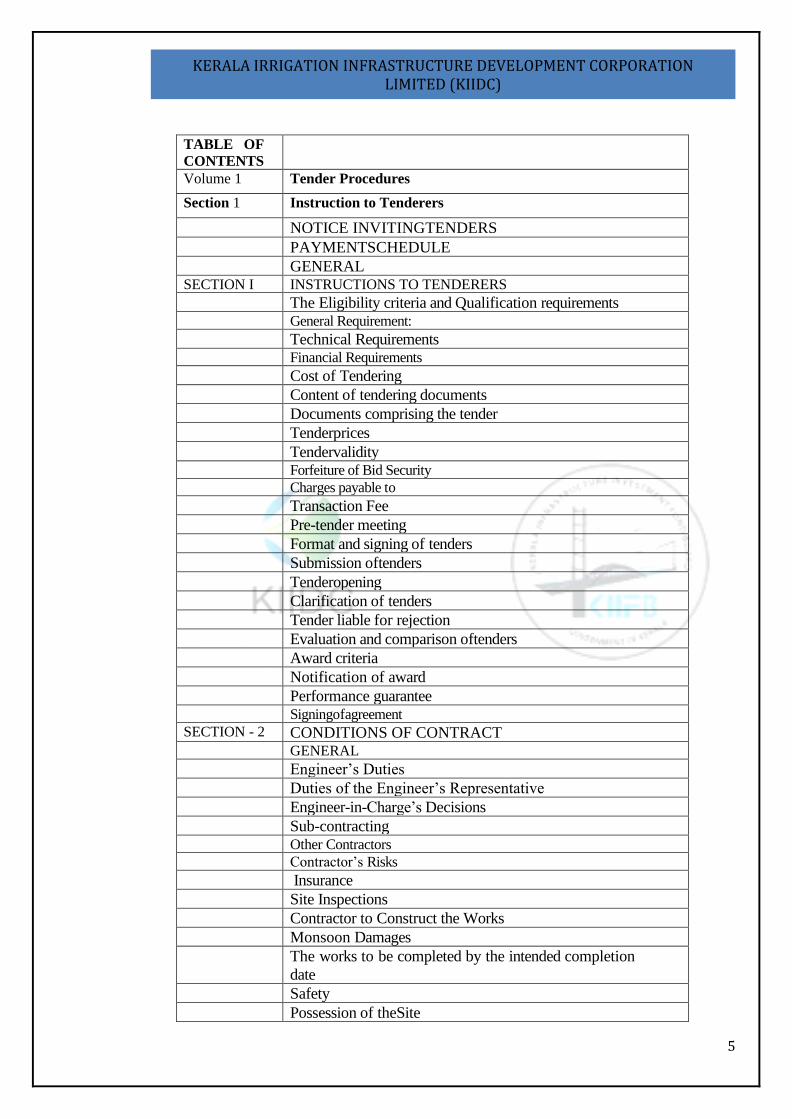
TABLE OF
CONTENTS
Volume 1 Tender Procedures
Section 1 Instruction to Tenderers
NOTICE INVITINGTENDERS
PAYMENTSCHEDULE GENERAL SECTION I INSTRUCTIONS TO TENDERERS
The Eligibility criteria and Qualification requirements General Requirement:
Technical Requirements Financial Requirements
Cost of Tendering Content of tendering documents Documents comprising the tender Tenderprices Tendervalidity Forfeiture of Bid Security
Charges payable to
Transaction Fee Pre-tender meeting Format and signing of tenders Submission oftenders Tenderopening Clarification of tenders Tender liable for rejection Evaluation and comparison oftenders Award criteria Notification of award Performance guarantee Signingofagreement
SECTION - 2 CONDITIONS OF CONTRACT GENERAL
Engineer’s Duties Duties of the Engineer’s Representative Engineer-in-Charge’s Decisions Sub-contracting Other Contractors
Contractor’s Risks
Insurance Site Inspections Contractor to Construct the Works Monsoon Damages The works to be completed by the intended completion
date Safety Possession of theSite
6
KERALA IRRIGATION INFRASTRUCTURE DEVELOPMENT CORPORATION LIMITED (KIIDC)
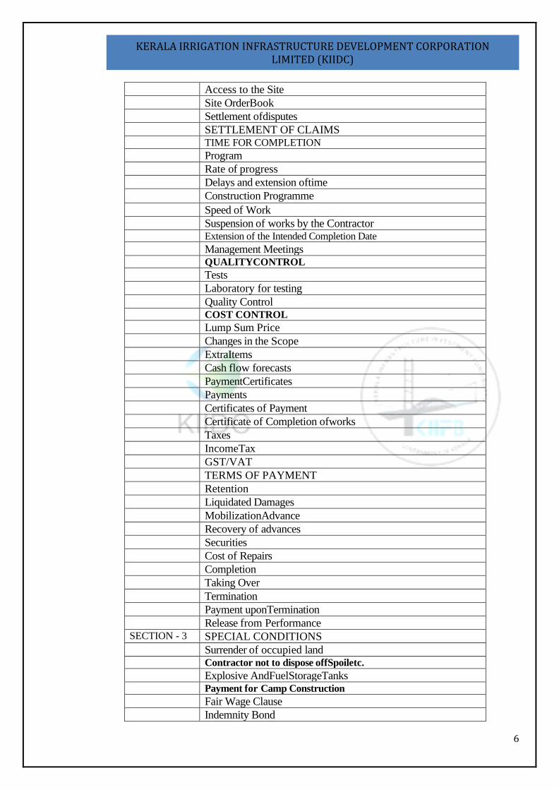
Access to the Site Site OrderBook Settlement ofdisputes SETTLEMENT OF CLAIMS TIME FOR COMPLETION
Program Rate of progress Delays and extension oftime Construction Programme
Speed of Work Suspension of works by the Contractor Extension of the Intended Completion Date
Management Meetings QUALITYCONTROL
Tests Laboratory for testing Quality Control COST CONTROL
Lump Sum Price Changes in the Scope ExtraItems Cash flow forecasts PaymentCertificates Payments Certificates of Payment Certificate of Completion ofworks Taxes IncomeTax GST/VAT TERMS OF PAYMENT Retention Liquidated Damages MobilizationAdvance Recovery of advances Securities Cost of Repairs Completion Taking Over Termination Payment uponTermination Release from Performance SECTION - 3 SPECIAL CONDITIONS Surrender of occupied land Contractor not to dispose offSpoiletc.
Explosive AndFuelStorageTanks Payment for Camp Construction
Fair Wage Clause Indemnity Bond
7
KERALA IRRIGATION INFRASTRUCTURE DEVELOPMENT CORPORATION LIMITED (KIIDC)
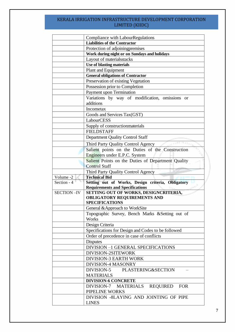
Compliance with LabourRegulations Liabilities of the Contractor
Protection of adjoiningpremises Work during night or on Sundays and holidays
Layout of materialsstacks Use of blasting materials
Plant and Equipment General obligations of Contractor
Preservation of existing Vegetation Possession prior to Completion Payment upon Termination Variations by way of modification, omissions or
additions Incometax Goods and Services Tax(GST) LabourCESS Supply of constructionmaterials FIELDSTAFF Department Quality Control Staff
Third Party Quality Control Agency Salient points on the Duties of the Construction
Engineers under E.P.C. System Salient Points on the Duties of Department Quality
Control Staff Third Party Quality Control Agency Volume -2 Technical Bid
Section - 4 Setting out of Works, Design criteria, Obligatory
Requirements and Specifications
SECTION –IV SETTING OUT OF WORKS, DESIGNCRITERIA,
OBLIGATORY REQUIREMENTS AND
SPECIFICATIONS
General &Approach to WorkSite Topographic Survey, Bench Marks &Setting out of
Works Design Criteria Specifications for Design and Codes to be followed Order of precedence in case of conflicts Disputes DIVISION –1 GENERAL SPECIFICATIONS DIVISION-2SITEWORK DIVISION-3 EARTH WORK DIVISION-4 MASONRY DIVISION-5 PLASTERING&SECTION –
MATERIALS DIVISION-6 CONCRETE
DIVISION-7 MATERIALS REQUIRED FOR
PIPELINE WORKS DIVISION -8LAYING AND JOINTING OF PIPE
LINES
8
KERALA IRRIGATION INFRASTRUCTURE DEVELOPMENT CORPORATION LIMITED (KIIDC)
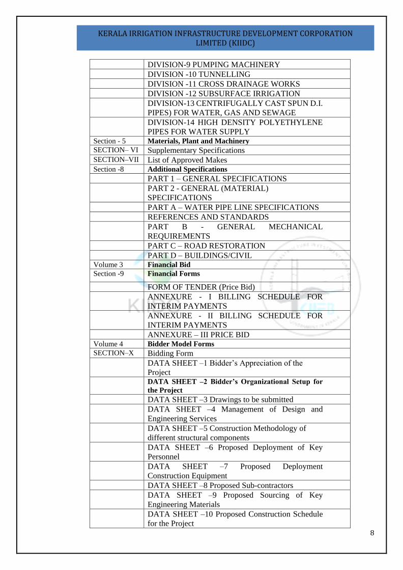
DIVISION-9 PUMPING MACHINERY DIVISION -10 TUNNELLING DIVISION -11 CROSS DRAINAGE WORKS DIVISION -12 SUBSURFACE IRRIGATION DIVISION-13 CENTRIFUGALLY CAST SPUN D.I.
PIPES) FOR WATER, GAS AND SEWAGE DIVISION-14 HIGH DENSITY POLYETHYLENE
PIPES FOR WATER SUPPLY Section - 5 Materials, Plant and Machinery
SECTION– VI Supplementary Specifications SECTION–VII List of Approved Makes Section -8 Additional Specifications
PART 1 – GENERAL SPECIFICATIONS PART 2 - GENERAL (MATERIAL)
SPECIFICATIONS PART A – WATER PIPE LINE SPECIFICATIONS REFERENCES AND STANDARDS PART B - GENERAL MECHANICAL
REQUIREMENTS PART C – ROAD RESTORATION PART D – BUILDINGS/CIVIL Volume 3 Financial Bid
Section -9 Financial Forms
FORM OF TENDER (Price Bid) ANNEXURE - I BILLING SCHEDULE FOR
INTERIM PAYMENTS ANNEXURE - II BILLING SCHEDULE FOR
INTERIM PAYMENTS ANNEXURE – III PRICE BID Volume 4 Bidder Model Forms
SECTION–X Bidding Form DATA SHEET –1 Bidder’s Appreciation of the
Project DATA SHEET –2 Bidder’s Organizational Setup for
the Project
DATA SHEET –3 Drawings to be submitted DATA SHEET –4 Management of Design and
Engineering Services DATA SHEET –5 Construction Methodology of
different structural components DATA SHEET –6 Proposed Deployment of Key
Personnel DATA SHEET –7 Proposed Deployment
Construction Equipment DATA SHEET –8 Proposed Sub-contractors DATA SHEET –9 Proposed Sourcing of Key
Engineering Materials DATA SHEET –10 Proposed Construction Schedule
for the Project
9
KERALA IRRIGATION INFRASTRUCTURE DEVELOPMENT CORPORATION LIMITED (KIIDC)
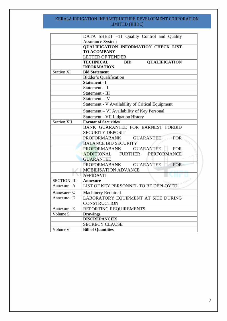
DATA SHEET –11 Quality Control and Quality
Assurance System QUALIFICATION INFORMATION CHECK LIST
TO ACOMPANY
LETTER OF TENDER TECHNICAL BID QUALIFICATION
INFORMATION
Section XI Bid Statement
Bidder’s Qualification Statement - I
Statement - II Statement - III Statement - IV Statement - V Availability of Critical Equipment
Statement – VI Availability of Key Personal
Statement - VII Litigation History Section XII Format of Securities
BANK GUARANTEE FOR EARNEST FORBID
SECURITY DEPOSIT PROFORMABANK GUARANTEE FOR
BALANCE BID SECURITY PROFORMABANK GUARANTEE FOR
ADDITIONAL FURTHER PERFORMANCE
GUARANTEE PROFORMABANK GUARANTEE FOR
MOBILISATION ADVANCE AFFIDAVIT SECTION–III Annexure
Annexure– A LIST OF KEY PERSONNEL TO BE DEPLOYED
Annexure– C Machinery Required Annexure– D LABORATORY EQUIPMENT AT SITE DURING
CONSTRUCTION Annexure– E REPORTING REQUIREMENTS Volume 5 Drawings
DISCREPANCIES
SECRECY CLAUSE Volume 6 Bill of Quantities
10
KERALA IRRIGATION INFRASTRUCTURE DEVELOPMENT CORPORATION LIMITED (KIIDC)
THIS PAGE HAS BEEN LEFT BLANK
INTENTIONALLY
11
KERALA IRRIGATION INFRASTRUCTURE DEVELOPMENT CORPORATION LIMITED (KIIDC)
Volume 1: Tender Procedures
13
KERALA IRRIGATION INFRASTRUCTURE DEVELOPMENT CORPORATION LIMITED (KIIDC)
Section I: Instruction to Tenderers
14
KERALA IRRIGATION INFRASTRUCTURE DEVELOPMENT CORPORATION LIMITED (KIIDC)
NOTICE INVITINGTENDERS OFFICE OF THE MANAGING DIRECTOR,
KERALA IRRIGATION INFRASTRUCTURE DEVELOPMENT CORPORATION LIMITED
‘e’ Procurement Notice Ref. No.: KIIDC / Projects / EPC / 2 / 2020-21, Dated: 10/ 02/2021
Managing Director, Kerala Irrigation Infrastructure Development Corporation Limited invites bids from eligible bidders for the above work under Engineering, Procurement, and Construction (EPC) system.
a) Scope of Work:
The scope of work includes Investigation, Survey, Design, Construction, Testing, Commissioning and Construction of ChittoorMoolathara Right Bank Canal Extension from Korayar to Varattayar(civil works), through the acquired land with a Defect Liability Period [DLP] of 5 years from the date of issue of completion certificate in Kozhinjampara Firka in Palakkad District, Kerala. The EPC contactor is bound to design and Implement the project adopting the latest technologies in Engineering Sector, within the constraint of limited width of acquired land, approved hydraulic particulars of the canal, operation and maintenance of canal etc.
b) Salient components of the Scheme: By keeping the approved hydraulic particulars, convey the water through pipe .conduit or by other means, within the restricted land width of 10m, renovation of 14 numbers of pond with strengthening of the bank, providing necessary man hole,Control valves to regulate the flow, one way valve at 250 to 300m interval for drawing water from the canal for irrigation purpose (providing sluice oulets) , inspection chambers of size 6x6x5m of 10 no:s , strengthening/ protection of river bank at outlet of canal, wherever necessary to the extent required as approved by Engineer in charge , providing lift irrigation scheme from the proposed pipe line to the highest elevated area for an area of 520 ht with an allowance of 10% variation.except in rocky area.The approximate canal length - 6430M consists of open conduit of 2710m, Syphon 210m, aqueduct 3510m, and tunnel of 660m. The EPC agency should conduct detailed investigation, including Soil Investigation, Design and construction, using appropriate technology in an economical manner with the site constraints. (Details are described in Schedule A)
15
KERALA IRRIGATION INFRASTRUCTURE DEVELOPMENT CORPORATION LIMITED (KIIDC)
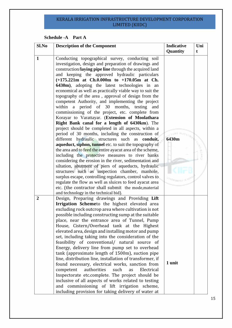
Schedule -A Part A
Sl.No Description of the Component Indicative
Quantity
Uni
t
1 Conducting topographical survey, conducting soil
investigation, design and preparation of drawings and
construction/laying pipe line through the acquired land
and keeping the approved hydraulic particulars
(+175.221m at Ch.0.000m to +170.05m at Ch.
6430m), adopting the latest technologies in an
economical as well as practically viable way to suit the
topography of the area , approval of design from the
competent Authority, and implementing the project
within a period of 30 months, testing and
commissioning of the project, etc. complete from
Korayar to Varattayar. (Extension of Moolathara
Right Bank canal for a length of 6430km). The
project should be completed in all aspects, within a
period of 30 months, including the construction of
different hydraulic structures such as conduit,
aqueduct, siphon, tunnel etc. to suit the topography of
the area and to feed the entire ayacut area of the scheme,
including the protective measures to river banks
considering the erosion in the river, sedimentation and
siltation, abutment of piers of aqueducts, hydraulic
structures such as inspection chamber, manhole,
surplus escape, controlling regulators, control valves to
regulate the flow as well as sluices to feed ayacut area
etc. (the contractor shall submit the mode,material and technology in the technical bid).
6430m
2 Design, Preparing drawings and Providing Lift Irrigation Schemeto the highest elevated area excluding rock outcrop area where cultivation is not possible including constructing sump at the suitable place, near the entrance area of Tunnel, Pump House, Cistern/Overhead tank at the Highest elevated area, design and installing motor and pump set, including taking into the consideration of the feasibility of conventional/ natural source of Energy, delivery line from pump set to overhead tank (approximate length of 1500m), suction pipe line, distribution line, installation of transformer, if found necessary, electrical works, sanction from competent authorities such as Electrical Inspectorate etc.complete. The project should be inclusive of all aspects of works related to testing and commissioning of lift irrigation scheme, including provision for taking delivery of water at
1 unit
16
KERALA IRRIGATION INFRASTRUCTURE DEVELOPMENT CORPORATION LIMITED (KIIDC)
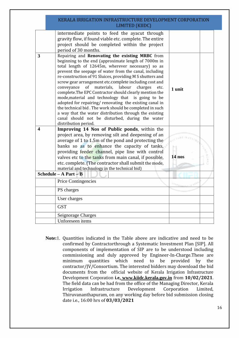
Note:1. Quantities indicated in the Table above are indicative and need to be confirmed by Contractorthrough a Systematic Investment Plan [SIP]. All components of implementation of SIP are to be understood including commissioning and duly approved by Engineer-In-Charge.These are minimum quantities which need to be provided by the contractor/JV/Consortium. The interested bidders may download the bid documents from the official website of Kerala Irrigation Infrastructure
Development Corporation i.e, www.kiidc.kerala.gov.in from 10/02/2021. The field data can be had from the office of the Managing Director, Kerala Irrigation Infrastructure Development Corporation Limited, Thiruvananthapuram, on any working day before bid submission closing date i.e., 16:00 hrs of 03/03/2021
intermediate points to feed the ayacut through gravity flow, if found viable etc. complete. The entire project should be completed within the project period of 30 months.
3 Repairing and Renovating the existing MRBC from beginning to the end (approximate length of 7000m in total length of 12645m, wherever necessary) so as prevent the seepage of water from the canal, including re-construction of 91 Sluices, providing M S shutters and screw gear arrangement etc.complete including cost and conveyance of materials, labour charges etc. complete.The EPC Contractor should clearly mention the mode,material and technology that is going to be adopted for repairing/ renovating the existing canal in the technical bid . The work should be completed in such a way that the water distribution through the existing canal should not be disturbed, during the water distribution period.
1 unit
4 Improving 14 Nos of Public ponds, within the project area, by removing silt and deepening of an average of 1 to 1.5m of the pond and protecting the banks so as to enhance the capacity of tanks, providing feeder channel, pipe line with control valves etc to the tanks from main canal, if possible, etc. complete. (The contractor shall submit the mode, material and technology in the technical bid)
14 nos
Schedule – A Part – B
Price Contingencies
PS charges
User charges
GST
Seignorage Charges
Unforeseen items
19
KERALA IRRIGATION INFRASTRUCTURE DEVELOPMENT CORPORATION LIMITED (KIIDC)
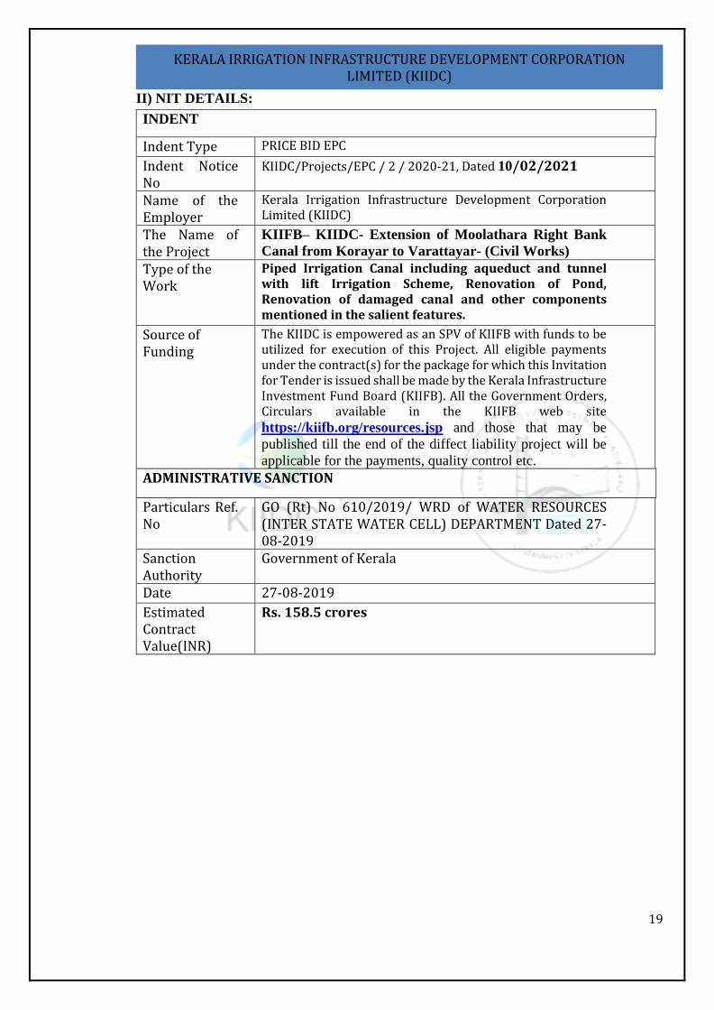
II) NIT DETAILS:
INDENT
Indent Type PRICE BID EPC
Indent Notice No
KIIDC/Projects/EPC / 2 / 2020-21, Dated 10/02/2021
Name of the Employer
Kerala Irrigation Infrastructure Development Corporation Limited (KIIDC)
The Name of the Project
KIIFB– KIIDC- Extension of Moolathara Right Bank
Canal from Korayar to Varattayar- (Civil Works)
Type of the Work
Piped Irrigation Canal including aqueduct and tunnel with lift Irrigation Scheme, Renovation of Pond, Renovation of damaged canal and other components mentioned in the salient features.
Source of Funding
The KIIDC is empowered as an SPV of KIIFB with funds to be utilized for execution of this Project. All eligible payments under the contract(s) for the package for which this Invitation for Tender is issued shall be made by the Kerala Infrastructure Investment Fund Board (KIIFB). All the Government Orders, Circulars available in the KIIFB web site https://kiifb.org/resources.jsp and those that may be
published till the end of the diffect liability project will be
applicable for the payments, quality control etc. ADMINISTRATIVE SANCTION
Particulars Ref. No
GO (Rt) No 610/2019/ WRD of WATER RESOURCES (INTER STATE WATER CELL) DEPARTMENT Dated 27-08-2019
Sanction Authority
Government of Kerala
Date 27-08-2019
Estimated Contract Value(INR)
Rs. 158.5 crores
20
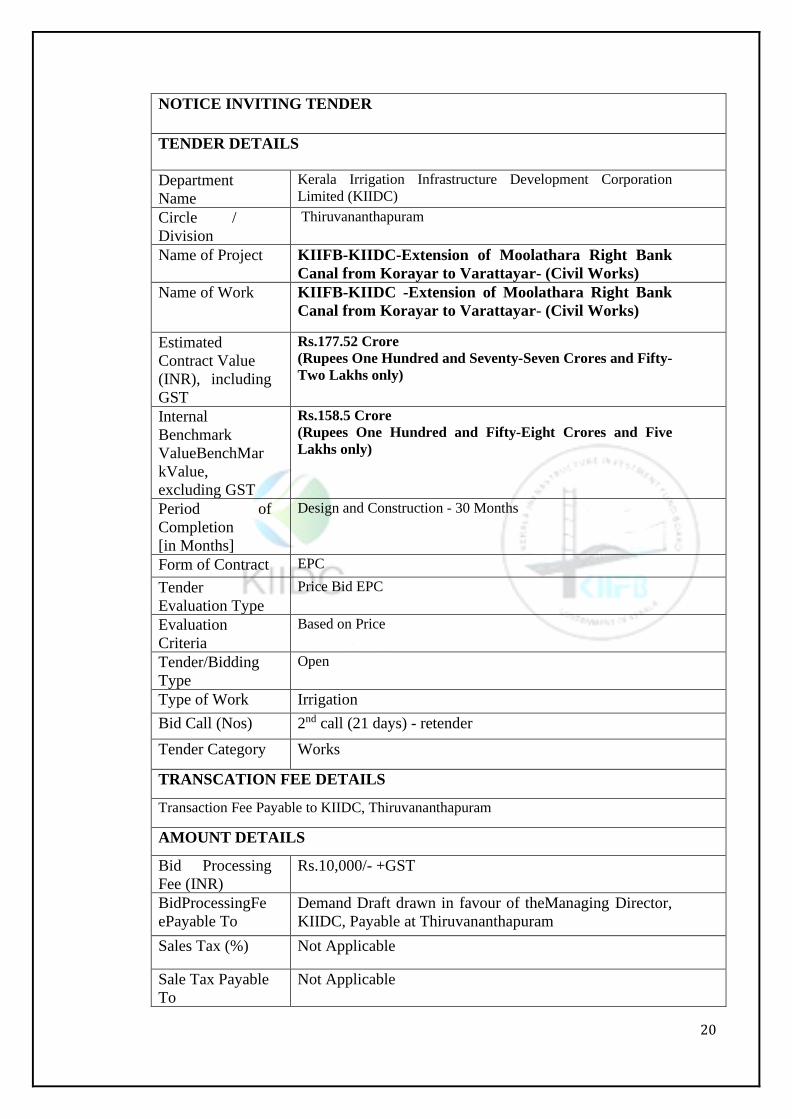
NOTICE INVITING TENDER
TENDER DETAILS
Department
Name
Kerala Irrigation Infrastructure Development Corporation
Limited (KIIDC)
Circle /
Division
Thiruvananthapuram
Name of Project KIIFB-KIIDC-Extension of Moolathara Right Bank
Canal from Korayar to Varattayar- (Civil Works)
Name of Work KIIFB-KIIDC -Extension of Moolathara Right Bank
Canal from Korayar to Varattayar- (Civil Works)
Estimated
Contract Value
(INR), including
GST
Rs.177.52 Crore (Rupees One Hundred and Seventy-Seven Crores and Fifty-
Two Lakhs only)
Internal
Benchmark
ValueBenchMar
kValue,
excluding GST
Rs.158.5 Crore (Rupees One Hundred and Fifty-Eight Crores and Five
Lakhs only)
Period of
Completion
[in Months]
Design and Construction - 30 Months
Form of Contract EPC
Tender
Evaluation Type
Price Bid EPC
Evaluation
Criteria
Based on Price
Tender/Bidding
Type
Open
Type of Work Irrigation
Bid Call (Nos) 2nd call (21 days) - retender
Tender Category Works
TRANSCATION FEE DETAILS
Transaction Fee Payable to KIIDC, Thiruvananthapuram
AMOUNT DETAILS
Bid Processing
Fee (INR)
Rs.10,000/- +GST
BidProcessingFe
ePayable To
Demand Draft drawn in favour of theManaging Director,
KIIDC, Payable at Thiruvananthapuram
Sales Tax (%) Not Applicable
Sale Tax Payable
To
Not Applicable
21
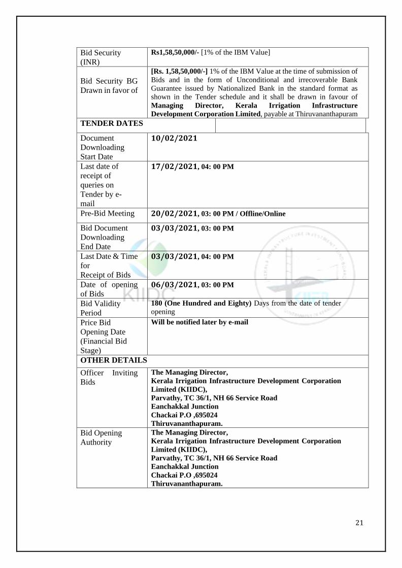
Bid Security
(INR)
Rs1,58,50,000/- [1% of the IBM Value]
Bid Security BG
Drawn in favor of
[Rs. 1,58,50,000/-] 1% of the IBM Value at the time of submission of
Bids and in the form of Unconditional and irrecoverable Bank
Guarantee issued by Nationalized Bank in the standard format as
shown in the Tender schedule and it shall be drawn in favour of
Managing Director, Kerala Irrigation Infrastructure
Development Corporation Limited, payable at Thiruvananthapuram
TENDER DATES
Document
Downloading
Start Date
10/02/2021
Last date of
receipt of
queries on
Tender by e-
17/02/2021, 04: 00 PM
Pre-Bid Meeting 20/02/2021, 03: 00 PM / Offline/Online
Bid Document
Downloading
End Date
03/03/2021, 03: 00 PM
Last Date & Time
for
Receipt of Bids
03/03/2021, 04: 00 PM
Date of opening
of Bids 06/03/2021, 03: 00 PM
Bid Validity
Period
180 (One Hundred and Eighty) Days from the date of tender
opening
Price Bid
Opening Date
(Financial Bid
Stage)
Will be notified later by e-mail
OTHER DETAILS
Officer Inviting
Bids
The Managing Director, Kerala Irrigation Infrastructure Development Corporation
Limited (KIIDC),
Parvathy, TC 36/1, NH 66 Service Road
Eanchakkal Junction
Chackai P.O ,695024
Thiruvananthapuram.
Bid Opening
Authority
The Managing Director, Kerala Irrigation Infrastructure Development Corporation
Limited (KIIDC),
Parvathy, TC 36/1, NH 66 Service Road
Eanchakkal Junction
Chackai P.O ,695024
Thiruvananthapuram.
22
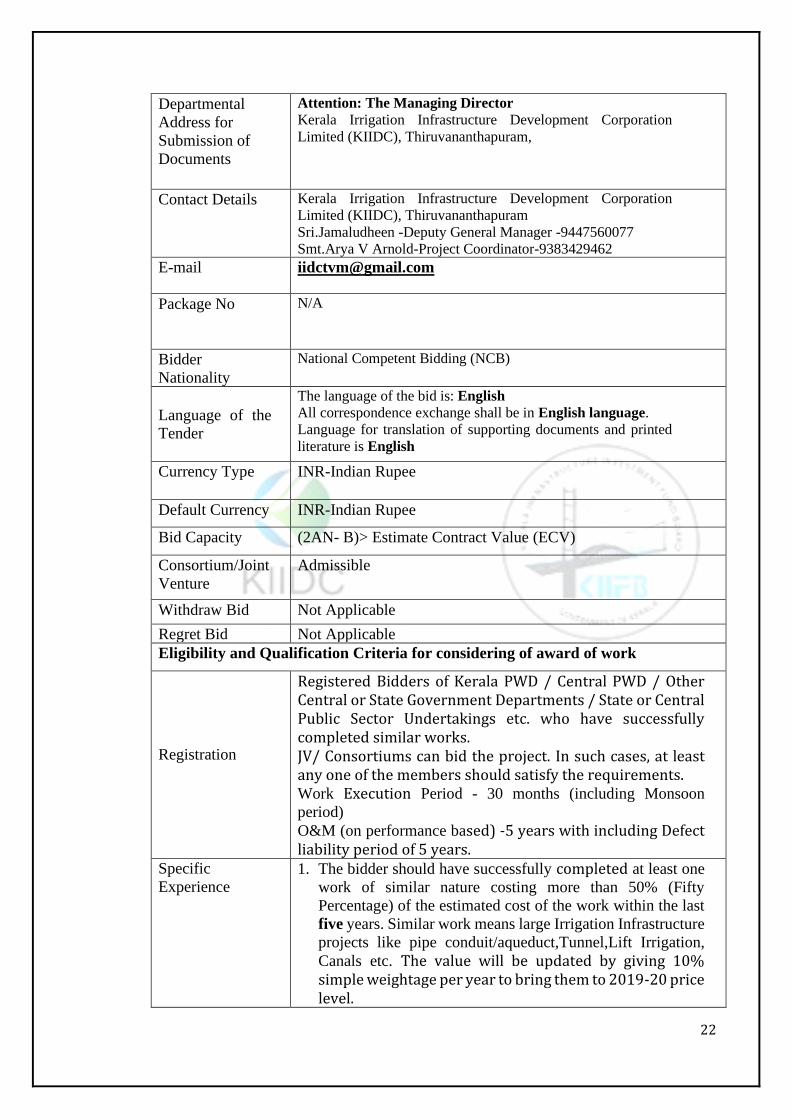
Departmental
Address for
Submission of
Documents
Attention: The Managing Director Kerala Irrigation Infrastructure Development Corporation
Limited (KIIDC), Thiruvananthapuram,
Contact Details Kerala Irrigation Infrastructure Development Corporation
Limited (KIIDC), Thiruvananthapuram
Sri.Jamaludheen -Deputy General Manager -9447560077
Smt.Arya V Arnold-Project Coordinator-9383429462
E-mail [email protected]
Package No N/A
Bidder
Nationality
National Competent Bidding (NCB)
Language of the
Tender
The language of the bid is: English All correspondence exchange shall be in English language. Language for translation of supporting documents and printed
literature is English
Currency Type INR-Indian Rupee
Default Currency INR-Indian Rupee
Bid Capacity (2AN- B)> Estimate Contract Value (ECV)
Consortium/Joint
Venture
Admissible
Withdraw Bid Not Applicable
Regret Bid Not Applicable
Eligibility and Qualification Criteria for considering of award of work
Registration
Registered Bidders of Kerala PWD / Central PWD / Other Central or State Government Departments / State or Central Public Sector Undertakings etc. who have successfully completed similar works. JV/ Consortiums can bid the project. In such cases, at least any one of the members should satisfy the requirements. Work Execution Period - 30 months (including Monsoon
period) O&M (on performance based) -5 years with including Defect liability period of 5 years.
Specific
Experience 1. The bidder should have successfully completed at least one
work of similar nature costing more than 50% (Fifty
Percentage) of the estimated cost of the work within the last
five years. Similar work means large Irrigation Infrastructure
projects like pipe conduit/aqueduct,Tunnel,Lift Irrigation,
Canals etc. The value will be updated by giving 10% simple weightage per year to bring them to 2019-20 price level.

23
2. The bidder’s net worth for the last financial year shall not be less than 10% of the Internal Benchmark value. In this regard certificate issued by Chartered Accountant in the current financial year shall be enclosed by the bidder.
3. The bidder as a prime contractor should have Satisfactorily Completed atleast laying pipeline works of one water supply project/sewerage pipeline network/canal pipeline with mimimum 1 yearwith project cost not less than Rs. 50,00,00,000/- during the last five financial years ending with 2019-20. The value will be updated by giving 10% simple weightage per year to bring them to 2019-20 price level. If done in JV the bidder shall submit proof of completing the whole.
4. The bidder who has applied for/ availed "Corporate Debt Restructuring" (CDR) or "Strategic Debt Restructuring" (SDR) in the last Five (5) financial years is not eligible to participate in the bid. In regards to this clause, a certificate issued by the Chartered Accountant in the current financial year shall be uploaded by the bidder.
5. If the design proposed is with MS pipes, DI pipes, HDPE pipes and CPVC pipes, the bidder has to submit copies of Memorandum of Understanding (MoU) with manufacturers having satisfactory manufacturing experience along with BIS license for a period of not less than five years. The Memorandum of Understanding (MoU) should clearly indicate that the manufacturer shall supply the agreement quantity for this work.
Technical
Requirement 6. The bidder should have successfully completed atleast one
steel/MS pipe /ductile iron pipe, work of minimum 450Ton
in the above contract or in any other contract during the past
five years.
Note: Proportionate Quantities will also be considered at
the time of evaluation for the completed works of similar
nature.
7. The bidder should enclose experience certificates in support
of technical criteria / requirement issued by the Engineer-In-
Chief of the State / Central Government Departments /
Undertakings, not below the rank of Executive Engineer or
Equivalent and countersigned by the next higher authority
not below the rank of Superintending Engineer.
8. The bidders should furnish the particulars of Quality Control
Testing Lab owned or tie up with established quality control
laboratories.
24
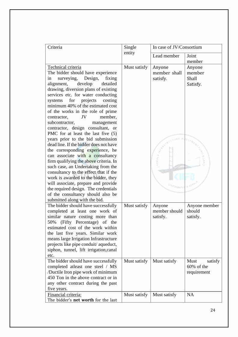
Criteria Single
entity
In case of JV/Consortium
Lead member Joint
member
Technical criteria
The bidder should have experience
in surveying, Design, fixing
alignment, develop detailed
drawing, diversion plans of existing
services etc. for water conducting
systems for projects costing
minimum 40% of the estimated cost
of the works in the role of prime
contractor, JV member,
subcontractor, management
contractor, design consultant, or
PMC for at least the last five (5)
years prior to the bid submission
dead line. If the bidder does not have
the corresponding experience, he
can associate with a consultancy
firm qualifying the above criteria. In
such case, an Undertaking from the
consultancy to the effect that if the
work is awarded to the bidder, they
will associate, prepare and provide
the required design. The credentials
of the consultancy should also be
submitted along with the bid.
Must satisfy Anyone member shall satisfy.
Anyone member Shall Satisfy.
The bidder should have successfully
completed at least one work of
similar nature costing more than
50% (Fifty Percentage) of the
estimated cost of the work within
the last five years. Similar work
means large Irrigation Infrastructure
projects like pipe conduit/ aqueduct,
siphon, tunnel, lift irrigation,canal
etc.
Must satisfy Anyone
member should
satisfy.
Anyone member
should
satisfy.
The bidder should have successfully
completed atleast one steel / MS
/Ductile Iron pipe work of minimum
450 Ton in the above contract or in
any other contract during the past
five years.
Must satisfy Must satisfy Must satisfy
60% of the
requirement
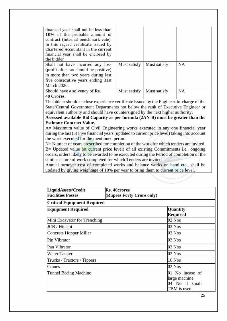
Financial criteria: The bidder’s net worth for the last
Must satisfy Must satisfy NA
25
financial year shall not be less than 10% of the probable amount of contract (internal benchmark vale). In this regard certificate issued by Chartered Accountant in the current financial year shall be enclosed by the bidder
Shall not have incurred any loss
(profit after tax should be positive)
in more than two years during last
five consecutive years ending 31st
March 2020.
Must satisfy Must satisfy NA
Should have a solvency of Rs.
40 Crores.
Must satisfy Must satisfy NA
The bidder should enclose experience certificate issued by the Engineer-in-charge of the
State/Central Government Departments not below the rank of Executive Engineer or
equivalent authority and should have countersigned by the next higher authority.
Assessed available Bid Capacity as per formula (2AN-B) must be greater than the
Estimate Contract Value.
A= Maximum value of Civil Engineering works executed in any one financial year
during the last (5) Five financial years (updated to current price level) taking into account
the work executed for the mentioned period.
N= Number of years prescribed for completion of the work for which tenders are invited.
B= Updated value (at current price level) of all existing Commitments i.e., ongoing
orders, orders likely to be awarded to be executed during the Period of completion of the
similar nature of work completed for which Tenders are invited.
Annual turnover cost of completed works and balance works on hand etc., shall be
updated by giving weightage of 10% per year to bring them to current price level.
LiquidAssets/Credit
Facilities Posses
Rs. 40crores
(Rupees Forty Crore only)
Critical Equipment Required
Equipment Required Quantity
Required
Mini Excavator for Trenching 02 Nos
JCB / Hitachi 03 Nos
Concrete Hopper Miller 03 Nos
Pin Vibrator 03 Nos
Pan Vibrator 03 Nos
Water Tanker 02 Nos
Trucks / Tractors / Tippers 10 Nos
Cranes 02 Nos
Tunnel Boring Machine 01 No incase of
large machine
04 No if small
TBM is used
26
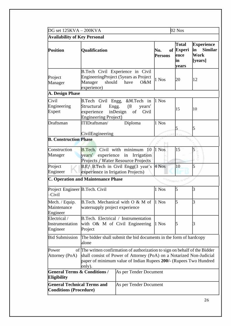
DG set 125KVA – 200KVA 02 Nos
Availability of Key Personal
Position
Qualification
No. of
Persons
Total
Experi
ence
in
years
Experience
in Similar
Work
[years]
Project
Manager
B.Tech Civil Experience in Civil
EngineeringProject (5years as Project
Manager should have O&M
experience)
1 Nos 20 12
A. Design Phase
Civil
Engineering
Expert
B.Tech Civil Engg, &M.Tech in Structural Engg. (8 years’ experience inDesign of Civil Engineering Project)
1 Nos
15 10
Draftsman ITIDraftsman/ Diploma
CivilEngineering
1 Nos
5 5
B. Construction Phase
Construction
Manager B.Tech. Civil with minimum 10 years’ experience in Irrigation Projects / Water Resource Projects
1 Nos 15 5
Project
Engineer B.E/ B.Tech in Civil Engg(3 year’s
experience in Irrigation Projects)
4 Nos 10 5
C. Operation and Maintenance Phase
Project Engineer
–Civil
B.Tech. Civil 1 Nos 5 3
Mech. / Equip.
Maintenance
Engineer
B.Tech. Mechanical with O & M of
watersupply project experience
1 Nos 5 3
Electrical /
Instrumentation
Engineer
B.Tech. Electrical / Instrumentation
with O& M of Civil Engineering
Project
1 Nos
5
3
Bid Submission The bidder shall submit the bid documents in the form of hardcopy
alone
Power of
Attorney (PoA)
The written confirmation of authorization to sign on behalf of the Bidder
shall consist of Power of Attorney (PoA) on a Notarized Non-Judicial
paper of minimum value of Indian Rupees 200/- (Rupees Two Hundred
only).
General Terms & Conditions /
Eligibility
As per Tender Document
General Technical Terms and
Conditions (Procedure)
As per Tender Document

27
Eligible Class of Contractors as
per G.O. M’s No.
As per Tender Document
General Terms and Conditions:
Bids are invited for the above-mentioned work from the eligible registered contractors in any respective Departments of Government of Kerala. The details of Tender conditions and terms can be down loaded from the the official website of Kerala Irrigation Infrastructure Development Corporation, Thiruvananthapurami.e, www.kiidc.kerala.gov.in Internal Benchmark Value is Rs158.5 Crore (Rupees OneHundred and Fifty-Eight Crores and Five lakhs only), excluding GST. The bidder has required to submit the hard copy of the bid along with a non refundablefee in the form of Demand Draft of Rs. 10,000/- + GST, drawn in any Nationalized Bank and in favour of the Managing Director, Kerala Irrigation Infrastructure Development Corporation, Thiruvananthapuram. Bid Security to be paid by way of unconditional and irrevocable Bank Guarantee or issued by any Nationalized Bank in the standard format as shown in the Bid document, drawn in favour of Managing Director, Kerala Irrigation Infrastructure Development Corporation Limited for Rs. 1, 58, 50,000/- (i.e., 1.00% of IBM Value) along with bids. The successful bidder should furnish Performance Guarantee 2.5% of Tender Contract Value at the time of agreement, of which 50% shall be treasury term deposit and the rest as Bank Guarantee. The proportionate value of Performance
Guarantee for CAPEX value will be returned after defect liability period of 5 years and the proportionate value of Performance Guarantee for OPEX value will be returned after completion of 5 years O&M period. The bidders can view/down load the bid documents from the official web site of Kerala Irrigation Infrastructure Development Corporation, Thiruvananthapuram i.e,
www.kiidc.kerala.gov.in
Note: - (i) The date stipulated above is firm and under no circumstances they will be
relaxed unless otherwise extended by an official notification or happen to be Public
Holiday.
(ii)The Bank Guarantee submitted by the success full bidder at the time of tender with
conditional obligations shall not be accepted and retained against Bid Security for
performance at the time of conclusion of contract.
(iii) Unconditional and irrevocable Bank Guarantee shall be obtained towards Bid
security for the entire specified amount at the time of concluding agreement)
The EPC Coctracor should follow the following clauses. The Department will carry out the technical bid evaluation solely based on the submiteed certificates / documents and open the price bids of the responsive bidders. All bidders may furnish hard copies of all documents in the office of the undersigned either personally or through courier or post within the stipulated date and time. If any successful bidder fails to submit the original hard copies and BG within the stipulated time the successful bidder will be suspended from participating in the tender on for a period of 3 (three) years. Besides this, the department shall invoke all processes of law including criminal prosecution of such defaulting bidder as an act of extreme deterrence to avoid delay in the tender process for execution of all development schemes taken up by the Government. Any
28
incorrectness/deviation noticed will be viewed seriously and apart from canceling the work duly forfeiting the Bid security, Criminal Action will be initiated including suspension of business. The bidders shall sign on all the statements, documents, certificates uploaded by him owning responsibility for their correctness/authenticity. The technical bid evaluation of the tenderers will be done on the certificates / documents submitted, towards qualification criteria furnished by them. Copy of Latest valid Income Tax Return along with proof of receipt and copy of PAN Card must be uploaded. Copy of GST Registration Certificate along with GSTIN No. obtained from respective Department and latest Clearance Certificate must be uploaded. GST and other statutory taxes and duties will be adopted time to time as per instructions of Government of Kerala Period of completion: 30 months + warranty as applicable. The date stipulated in the NIT is fixed and under no circumstances they will be relaxed under unless otherwise extended by an official notification or happen to be Public Holiday. Any other condition regarding receipt of tenders in conventional method appearing in the tender documents may please be treated as not applicable. Each bidder should demonstrate the availability of key and critical equipment either owned or leased as shown in the NIT. The bidders should furnish the particulars of Quality Control Testing Lab owned or tie up with established quality control laboratories. The bidder is subjected to be disqualified and liable for blacklisting and forfeiture of Bid
Security, if he is found to have misledor furnished false information in the
formsstatements/ certificates submitted in proof of qualification requirements.
Even while execution of the work, if found that the contractor had produced false / fake
certificates of experience he will be liable for black listing and the contract will be liable
for termination and liable for forfeiture of Bid Security and all the amounts due to him.
Bidders shall submit a declaration without any reservation what so everthat the submitted
eligibility and qualification details, technical and financial bid are without any deviations
and are strictly in conformity with the documents issued by the employer.
Declaration should be given for the credentials submitted by the bidder.
The employer reserves the right to relax the conditions and required foreligibilityofthe
bidders in the public interest. The Bidder(s) shall not have any right to question the
decision taken by the employer in this regard.
29
Special Conditions:
The following details shall be provided by bidder in the Technical Bid
(a) Renovations proposed to be done in the existing canal network consisting of open
canal open flume, cut and cover etc from Moolathara Regulator (CH 0m to CH
15118m) (old)-details of mode and methodology that would be adopted.
(b) The conveyance system consisting of aqueducts, tunnels, syphon etc from (CH
15118 m-old) CH 0m-CH 6260m,(new)
i.) Discharge of 6.40m3/sec shall be ensured with bed level
from 175.221(CH 0m) ) to 170.050(CH 6260m)
ii.) For Aqueduct-Details regarding the material of the
aqueduct barrel and type of substructure supporting the
barrel (whether steel/concrete)
iii.) For tunnel-Methodology of tunnelling
iv.) For Syphon –Material that would be adopted
(c) Lift irrigation system (LIS)-Details regarding methodology of lifting (whether
direct lifting or using storage tank)
The work should be got tested as per relevant IS Codes and Standards approved by the
Department and third-Party Quality Control before the total supplies are delivered at site
or despatched from the factory. KIIDC will not take any liability and the cost of entire
removal of the defective material from the site shall be born by the
contractor/JV/Consortium.
The Bidder has to furnish self-declaration of Latest Present and Permanent Postal
Address along with e-mail id, Telephone Number, Mobile Number for Communication.
Any Changes in the above shall be communicated to the Tender Inviting Authority.
Failure to notify the changes prior to one month from the date of change of address, the
available address and details intimated will be deemed to fit for communication. It is the
responsibility of the bidder for any delay, loss in communication of any Correspondence.
The Managing Director, Kerala Irrigation Infrastructure Development Corporation
Limited reserves the right to reject any tender or drop the proposals for receiving the
tenders without assigning any reason. The details of rules and regulations and other
required information can be had at the above address during the office hours on all
working days.
The successful bidder shall furnish Performance Guarantee at 2.5% of Tender Contract
Value at the time of agreement. The proportionate value of Performance Guarantee for
CAPEX value will be returned after defect liability period of 5 years and the proportionate
value of Performance Guarantee for OPEX value will be returned after completion of
5years O&M period.
Bid Security noted against the work i.e., at 1% of estimate contract value should be paid
in the shape of BG in favor of Managing Director, Kerala Irrigation Infrastructure
Development Corporation Limited. 2.5% of the contract value without GST is the bid
security. The 50% of the bid security in the form of BG and rest in the form of treasury
deposit.Any changes is as per the relevant GO.
The balance Bid Security i.e., @ 1.5% of estimate contract value should be paid by B.G
30
for the amounts till the defect liability period is completed i.e., 5 years from the date of
completion of work to be paid at the time of entering into agreement. The BG's taken
earlier than the Tender Notice will not be valid.
The bidder who has applied for/ availed "Corporate Debt Restructuring" (CDR) or
“Strategic Debt Restructuring" (SDR) in the last Five (5) financial years is not eligible to
participate in the bid. In regards to this clause, a certificate issued by the Chartered
Accountant in the current financial year shall be uploaded by the bidder.
Employer reserves the right to cancel / alter the bid conditions at any time.
Any Tender or all the tenders can be cancelled without assigning any reasons. Conditional
tenders will not be considered.
For particulars, please apply to the Chief Engineer, KIIDC, Thiruvananthapuram and
clarification can be had till one day prior to the the last date of submission of bid.
If the tender is made by an individual, it shall be signed with full name and his address
shall be given if it is made by a firm. It shall be signed with the co-partnership name by
a member of the firm who shall also sign his own name and address of each member of
the firm shall be given. If the tender is made by corporation it shall be signed by the duly
authorized officer who shall produce with his tender satisfactory evidence of his
authorization. Such tendering corporation may be required before the contract executed
to furnish evidence of the corporate existence. In the case of Proprietary or partnership
firm it will be necessary to produce the certificate before mentioned for the proprietor or
proprietors and for each of the partners as the case may be. All documents of the Bid as required shall be typed or written in indelible ink and shall be signed by the Bidder or person duly authorized to sign on behalf of the Bidder. In the event of the tender being submitted by a partnership firm or joint venture/consortium, it must be signed by the lead partner holding a valid power-of attorney authorizing him to do so, such power of attorney to be produced with the tender, and it must disclose that the firm is duly registered under the Indian Partnership Act,1952
Note: - The tenderers particular attention is drawn to the sections and clauses in the
standard preliminary specification dealing with the following:
a) Test inspection and rejection of defective materials of Supplies.
Carriage
Construction works.
Water and Lighting.
Cleaning during progress and for delivery
Accidents
Delays
Particulars of payment.
The tenderer should closely pursue all the specifications Clause which govern the rates
for which is tendering. The Supplier has to fulfill all requirements in tender document.
Procedure for Submission of Bids:
Bidders may contact, Office of the Managing Director, Kerala Irrigation Infrastructure
Development Corporation Limited, for any clarifications, or information on any working
day during office hours.
The bidder has to submit the hard copy of the bid along with a non-refundable fee in the form of Demand Draft of Rs. 10,000/- + GST, drawn in any national Bank and in favour of the Managing Director, Kerala Irrigation Infrastructure Development Corporation, Thiruvananthapuram.
31
Bidders are requested to submit the bid in two stages
Stage – I: Eligibility and Technical Bid Stage
Stage – II: Financial Bid Stage
In the first stage the bidder shall submit cover 1 superscribing the name of work.The
bidder shall submit the document in support of the qualifications, eligibility details and
the technical bid. The bidder shall submit the documents in support of the above.
The bidder shall submit price bid in cover 2 under second stage which may include
proposals for financing to cover the scope of the work as per bid documents before the
bid submission closing date.Both covers to be enclosed in cover 3 and shall be submitted
before the stipulated date and time superscribing the name of work,bidders name and
address and address to the MD,KIIDC, Parvathy 36/1,NH66 Service Road Eanchakkal
Junction ,CHakai P.O Tvm 695024
All covers should be superscribed with name of work, bidders address and employeer
address mentioned above.
Bidders shall submit a declaration without any reservation whatsoever that the submitted
eligibility and qualification details, Techno-Commercial bid and financial bid are without
any deviations and are strictly in conformity with the documents issued by the Employer.
Declaration should begiven by the bidder for the correctness of the credentials submitted
by him.
The Bidders shall sign on all documents; includingand has to submit all documents
including Bid Security and Transaction fee payable through bank draft drawn on
Nationalized Bank, in favourof the Managing Director, Kerala Irrigation Infrastructure Development Corporation, Thiruvananthapuram etc. It is bidder’s responsility,
fortheir correctness/authenticity of documents submitted by them. The documents
without signature of the bidder will be considered as invalid documents and the same will
not be considered in evaluation of the bid.
Submission of original hard copies before opening of the Technical bid is mandatory.
The department / authority will carry out the technical bid evaluation solely based on
certificates / documents, BG towards Bid Security and open the price bids of the
responsive bidders after approval from the competent authority as per rules in force.
The department will not take any responsibility for any delay in receipt/non-receipt of
original BG towards Bid Security, certificates / Documents, from the successful bidder
before the stipulated time. On receipt of the documents, the Department will ensure the
genuinely of the BG towards Bid Security and all other certificates/documents submitted
by the bidder, in support of the qualification criteria before concluding the agreement.
If any successful bidder fails to execute the agreement, stipulating the conditions in the
bid document, the successful bidder will be suspended from participating in the tender
for a period of 3 (three) yearsand, the work shall either be entrusted to the second successful bidder, or rearranged, at the Risk &Cost of the original successful bidder, at the discretion of the tendering authority. Besides this, the department shall invoke
all processes of law including criminal prosecution of such defaulting bidder as an act of
extreme deterrence to avoid delay in the tender process for execution of all development
schemes taken up by the Government.
The successful (L1) bidder shall furnish the original hard copies of all the documents /
certificates / statements before concluding Agreement. Deactivation of Bidders:
The bidder (L1) found defaulting in submission of hard copies of original BG for Bid
Security to the Tender Inviting Authority on or before the tender stipulated time,the
bidder will be suspended / disqualified from participating in tenders for a period of 36
months from date of bid submission besides forfeiture of Bid Security. Other conditions
32
as per tender document are applicable.
Payment of Transaction Fee and Bid Security:
It is mandatory for all the participating bidders to pay the Transaction fee of a non refundable fee in the form of Demand Draft of Rs. 10,000/- + GST, drawn in any national Bank and in favour of the Managing Director, Kerala Irrigation Infrastructure Development Corporation, Thiruvananthapuram. The technical bid evaluation of the tenderers will be done on the certificates / documents,
towards qualification criteria furnished by them.
Required Tender Document Details:
Sl.
No.
Document Name Document
Type
1 Registration Certification Mandatory
2 Bid Security Mandatory
3 Transaction Fee Payable Mandatory
4 PAN CARD and Submission of latest Income Tax Return
alongwith Proof of Receipt
Mandatory
5 GST Registration Copy Mandatory
6 Declaration as per proforma attached in Tender Documents Mandatory
7 Annual Turnover Certificate certified by Chartered
Accountant
Mandatory
8 Similar Work Experience Certificate for the work
completedwithin the Specified period
Mandatory
9 Certificate in support of Existing Commitments Mandatory
10 Experience Certificate in support of quantities executed –
within block period
Mandatory
11 Liquidated Assets /Solvency Certificate from authorized
Bank
Mandatory
12 Scanned copy of declaration on Key Critical Equipment
owned on Non-Judicial stamp paper of Rs. 200
Mandatory
13 Qualification Certificate of Key Personnel Mandatory
14 MoU with manufactures / Suppliers of MS pipes, DI pipes
and CPVC pipes.
Mandatory
15 If any other documents as per Tender Document Optional
Tender Document:
The bidder is requested to download the tender document from KIIDC
website(kiidc.kerala.gov.in)and read all the terms and conditions mentioned in the tender
Document and seek clarification if in doubt from the Tender Inviting Authority. The
bidder has to keep track of any changes by viewing the addendum / Corrigendum's issued
by the Tender Inviting Authority on time-to-time basis in the website. The KIIDC shall
not be responsible for any claims/problems arising out of this.
Bid Submission Acknowledgement:
33
The user should complete all the processes and steps required for bid submission. KIIDC
is not responsible for incomplete bid submission by users. Users may also note that the
incomplete bids will not be processed by the Tender Inviting Authority.
Scope of the Project:
The scope of work includes “Investigation, Survey, Design, Construction, Testing,
Commissioning of Construction of Moolathara Right Bank Canal Extension from Korayar to Varattayar-(Civil Works), through the acquired land and providing providing lift irrigation scheme from the proposed pipe line to the highest elevated area for an area of …….except in rocky area with a Defect Liability Period [DLP] of 5 years from the date of issue of completion certificate in KozhinjamparaFirka in Palakkad District, Kerala”. The EPC contactor is bound to design and Implement the project adopting the latest technologies in Engineering Sector, within the constraint of limited width of acquiredland, approved hydraulic particulars of the canal, operation and maintenance of canal etc.
Appropriate construction procedure & technologies shall be adopted for providing
Irrigation system and various alternatives shall be explored for providing best possible
solutions at every stage of construction of, pipe laying, wherever necessary, approaches,
crossing etc.
Design Features of the Proposed Irrigation System
Flow control valves/Regulators shall be provided in the network to restrict excess flows
in thenetwork.
The Bidder shall conduct Topographic survey and establish Permanent Bench Marksat
regular intervals with reference to GTS/DGPS in order to execute the work. The EPC
Agency shall submit the Designs and Drawings duly taking into account& compatible
with the existing Irrigation system.
Contractor shall undertake design of water distribution work using latest versions of Water
Gemssoftware/EPA/Equvalent,Net Software Contractor shall submit all designs and
drawing with BOQ and estimates for approval by competentauthority.
After approval of the Drawings and Designs by the competent authority, the EPC Agency
shall submit detailed estimate along with BOQ’s based on the approved drawings which
will be approved by the Departmental/KIIDC authorities based on which the execution
shall be done. As per the provisions of EPC system, this shall form the basis of payment
within the overall percentage break up mentioned in the document.
The project shall be executed, completed and commissioned within the period of
completion, and the O&M of the project shall be carried out for a period of 5 years
including 5 years Defects Liability period (DLP) after completion of construction and
commissioning of the project, in compliance with the key Performance Indicators
specified.
It shall be expressly understood by the EPC Agency that the Drawings and details
appended at the time of bidding are only indicative but not exhaustive.
It shall be expressly understood the scope of the project, by the EPC Agency. i.e. by keeping the approved hydraulic particulars, convey the water through pipe conduit or by other means, within the acquired land width of 10m, renovation of 14 numbers of pond with strengthening of the bank, providing necessary man hole, inspection chamber, strengthening/ protection of river banks, Renovation of damaged portion of existing canal including construction of new sluices etc., and and providing providing lift irrigation scheme from the proposed pipe line to the highest elevated area for an area of …….except in rocky area.The approximate canal length - 6430Mconsists of open conduit of 2710m, Syphon 210m, aqueduct 3510m, and tunnel of 660m. The EPC agency should conduct detailed investigation, including
34
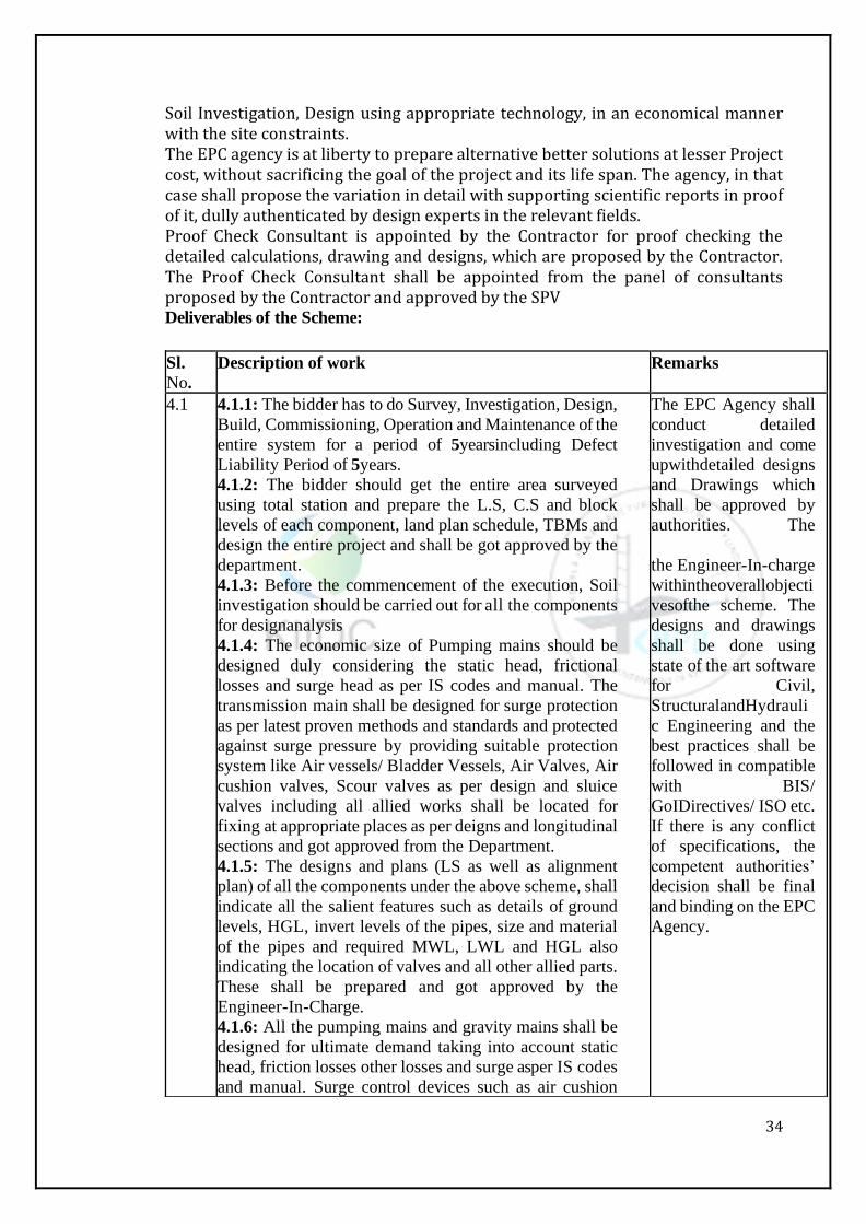
Soil Investigation, Design using appropriate technology, in an economical manner with the site constraints. The EPC agency is at liberty to prepare alternative better solutions at lesser Project cost, without sacrificing the goal of the project and its life span. The agency, in that case shall propose the variation in detail with supporting scientific reports in proof of it, dully authenticated by design experts in the relevant fields. Proof Check Consultant is appointed by the Contractor for proof checking the detailed calculations, drawing and designs, which are proposed by the Contractor. The Proof Check Consultant shall be appointed from the panel of consultants proposed by the Contractor and approved by the SPV
Deliverables of the Scheme:
Sl.
No.
Description of work Remarks
4.1 4.1.1: The bidder has to do Survey, Investigation, Design,
Build, Commissioning, Operation and Maintenance of the
entire system for a period of 5yearsincluding Defect
Liability Period of 5years.
4.1.2: The bidder should get the entire area surveyed
using total station and prepare the L.S, C.S and block
levels of each component, land plan schedule, TBMs and
design the entire project and shall be got approved by the
department.
4.1.3: Before the commencement of the execution, Soil
investigation should be carried out for all the components
for designanalysis
4.1.4: The economic size of Pumping mains should be
designed duly considering the static head, frictional
losses and surge head as per IS codes and manual. The
transmission main shall be designed for surge protection
as per latest proven methods and standards and protected
against surge pressure by providing suitable protection
system like Air vessels/ Bladder Vessels, Air Valves, Air
cushion valves, Scour valves as per design and sluice
valves including all allied works shall be located for
fixing at appropriate places as per deigns and longitudinal
sections and got approved from the Department.
4.1.5: The designs and plans (LS as well as alignment
plan) of all the components under the above scheme, shall
indicate all the salient features such as details of ground
levels, HGL, invert levels of the pipes, size and material
of the pipes and required MWL, LWL and HGL also
indicating the location of valves and all other allied parts.
These shall be prepared and got approved by the
Engineer-In-Charge.
4.1.6: All the pumping mains and gravity mains shall be
designed for ultimate demand taking into account static
head, friction losses other losses and surge asper IS codes
and manual. Surge control devices such as air cushion
The EPC Agency shall
conduct detailed
investigation and come
upwithdetailed designs
and Drawings which
shall be approved by
authorities. The
the Engineer-In-charge
withintheoverallobjecti
vesofthe scheme. The
designs and drawings
shall be done using
state of the art software
for Civil,
StructuralandHydrauli
c Engineering and the
best practices shall be
followed in compatible
with BIS/
GoIDirectives/ ISO etc.
If there is any conflict
of specifications, the
competent authorities’
decision shall be final
and binding on the EPC
Agency.
35
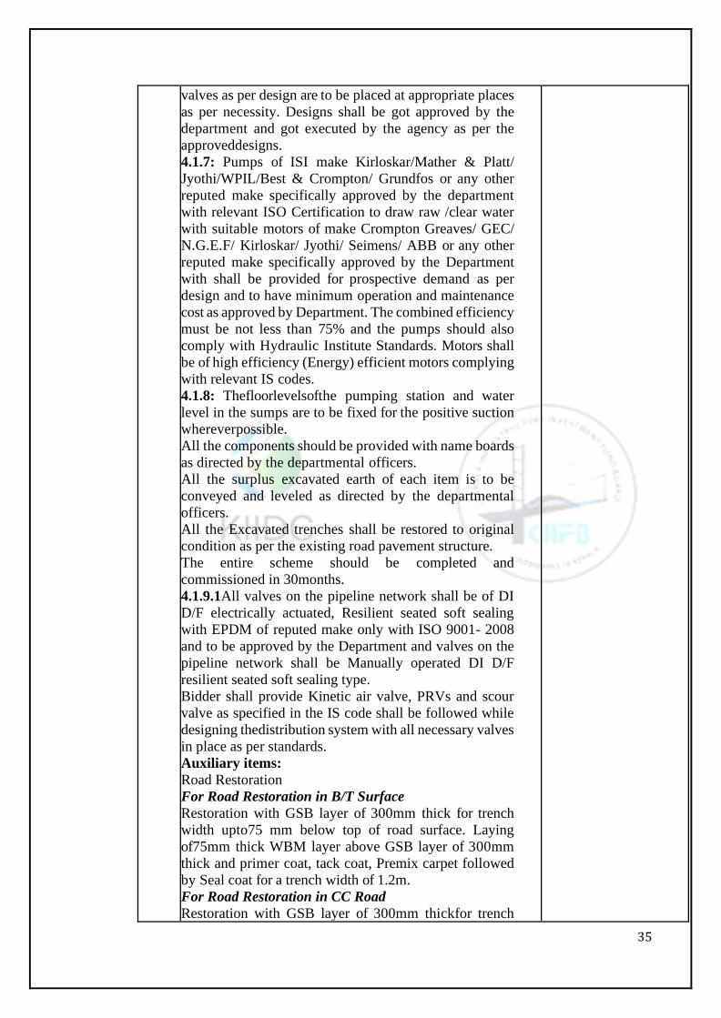
valves as per design are to be placed at appropriate places
as per necessity. Designs shall be got approved by the
department and got executed by the agency as per the
approveddesigns.
4.1.7: Pumps of ISI make Kirloskar/Mather & Platt/
Jyothi/WPIL/Best & Crompton/ Grundfos or any other
reputed make specifically approved by the department
with relevant ISO Certification to draw raw /clear water
with suitable motors of make Crompton Greaves/ GEC/
N.G.E.F/ Kirloskar/ Jyothi/ Seimens/ ABB or any other
reputed make specifically approved by the Department
with shall be provided for prospective demand as per
design and to have minimum operation and maintenance
cost as approved by Department. The combined efficiency
must be not less than 75% and the pumps should also
comply with Hydraulic Institute Standards. Motors shall
be of high efficiency (Energy) efficient motors complying
with relevant IS codes.
4.1.8: Thefloorlevelsofthe pumping station and water
level in the sumps are to be fixed for the positive suction
whereverpossible.
All the components should be provided with name boards
as directed by the departmental officers.
All the surplus excavated earth of each item is to be
conveyed and leveled as directed by the departmental
officers.
All the Excavated trenches shall be restored to original
condition as per the existing road pavement structure.
The entire scheme should be completed and
commissioned in 30months.
4.1.9.1All valves on the pipeline network shall be of DI
D/F electrically actuated, Resilient seated soft sealing
with EPDM of reputed make only with ISO 9001- 2008
and to be approved by the Department and valves on the
pipeline network shall be Manually operated DI D/F
resilient seated soft sealing type.
Bidder shall provide Kinetic air valve, PRVs and scour
valve as specified in the IS code shall be followed while
designing thedistribution system with all necessary valves
in place as per standards.
Auxiliary items:
Road Restoration
For Road Restoration in B/T Surface
Restoration with GSB layer of 300mm thick for trench
width upto75 mm below top of road surface. Laying
of75mm thick WBM layer above GSB layer of 300mm
thick and primer coat, tack coat, Premix carpet followed
by Seal coat for a trench width of 1.2m.
For Road Restoration in CC Road
Restoration with GSB layer of 300mm thickfor trench
36
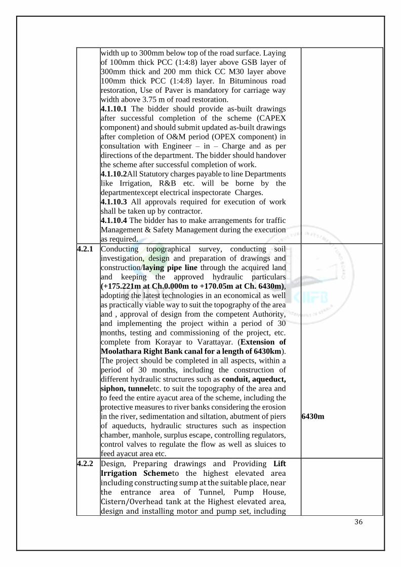
width up to 300mm below top of the road surface. Laying
of 100mm thick PCC (1:4:8) layer above GSB layer of
300mm thick and 200 mm thick CC M30 layer above
100mm thick PCC (1:4:8) layer. In Bituminous road
restoration, Use of Paver is mandatory for carriage way
width above 3.75 m of road restoration.
4.1.10.1 The bidder should provide as-built drawings
after successful completion of the scheme (CAPEX
component) and should submit updated as-built drawings
after completion of O&M period (OPEX component) in
consultation with Engineer – in – Charge and as per
directions of the department. The bidder should handover
the scheme after successful completion of work.
4.1.10.2All Statutory charges payable to line Departments
like Irrigation, R&B etc. will be borne by the
departmentexcept electrical inspectorate Charges.
4.1.10.3 All approvals required for execution of work
shall be taken up by contractor.
4.1.10.4 The bidder has to make arrangements for traffic
Management & Safety Management during the execution
as required.
4.2.1 Conducting topographical survey, conducting soil
investigation, design and preparation of drawings and
construction/laying pipe line through the acquired land
and keeping the approved hydraulic particulars
(+175.221m at Ch.0.000m to +170.05m at Ch. 6430m),
adopting the latest technologies in an economical as well
as practically viable way to suit the topography of the area
and , approval of design from the competent Authority,
and implementing the project within a period of 30
months, testing and commissioning of the project, etc.
complete from Korayar to Varattayar. (Extension of
Moolathara Right Bank canal for a length of 6430km).
The project should be completed in all aspects, within a
period of 30 months, including the construction of
different hydraulic structures such as conduit, aqueduct,
siphon, tunneletc. to suit the topography of the area and
to feed the entire ayacut area of the scheme, including the
protective measures to river banks considering the erosion
in the river, sedimentation and siltation, abutment of piers
of aqueducts, hydraulic structures such as inspection
chamber, manhole, surplus escape, controlling regulators,
control valves to regulate the flow as well as sluices to
feed ayacut area etc.
6430m
4.2.2 Design, Preparing drawings and Providing Lift Irrigation Schemeto the highest elevated area including constructing sump at the suitable place, near the entrance area of Tunnel, Pump House, Cistern/Overhead tank at the Highest elevated area, design and installing motor and pump set, including
37
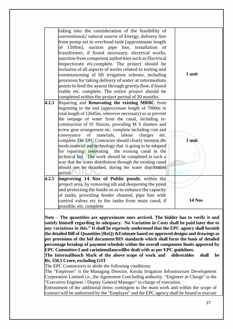
taking into the consideration of the feasibility of conventional/ natural source of Energy, delivery line from pump set to overhead tank (approximate length of 1500m), suction pipe line, installation of transformer, if found necessary, electrical works, sanction from competent authorities such as Electrical Inspectorate etc.complete. The project should be inclusive of all aspects of works related to testing and commissioning of lift irrigation scheme, including provision for taking delivery of water at intermediate points to feed the ayacut through gravity flow, if found viable etc. complete. The entire project should be completed within the project period of 30 months.
1 unit
4.2.3 Repairing and Renovating the existing MRBC from
beginning to the end (approximate length of 7000m in
total length of 12645m, wherever necessary) so as prevent
the seepage of water from the canal, including re-
construction of 91 Sluices, providing M S shutters and
screw gear arrangement etc. complete including cost and
conveyance of materials, labour charges etc.
complete.The EPC Contractor should clearly mention the
mode,material and technology that is going to be adopted
for repairing/ renovating the existing canal in the
technical bid . The work should be completed in such a
way that the water distribution through the existing canal
should not be disturbed, during the water distribution
period.
1 unit
4.2.5 Improving 14 Nos of Public ponds, within the project area, by removing silt and deepening the pond and protecting the banks so as to enhance the capacity of tanks, providing feeder channel, pipe line with control valves etc to the tanks from main canal, if possible, etc. complete
14 Nos
Note – The quantities are approximate ones arrived. The bidder has to verify it and
satisfy himself regarding its adequacy. No Variation in Costs shall be paid later due to
any variations in this.” It shall be expressly understood that the EPC agency shall furnish
the detailed Bill of Quantities (BoQ) &Estimate based on approved designs and drawings as
per provisions of the bid document/BIS standards which shall form the basis of detailed
percentage breakup of payment schedule within the overall component limits approved by
EPC Committee-I and variationsifanywillbe dealt with as per EPC guidelines.
The InternalBench Mark of the above scope of work and deliverables shall be
Rs. 158.5 Crore, excluding GST
The EPC Contractoris to abide the following conditions:
The "Employer" is the Managing Director, Kerala Irrigation Infrastructure Development
Corporation Limited i.e., the Agreement Concluding authority. "Engineer in Charge" is the
"Executive Engineer / Deputy General Manager" in charge of execution.
Entrustment of the additional items contingent to the main work and within the scope of
contract will be authorized by the "Employer" and the EPC agency shall be bound to execute
38
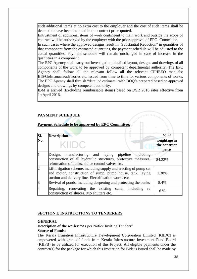
PAYMENT SCHEDULE
Payment Schedule to be approved by EPC Committee:
Sl.
No.
Description % of
weightage in
the contract
price
1 Design, manufacturing and laying pipeline including
construction of all hydraulic structures, protective measures,
reformation of banks, sluice control valves etc.
84.22%
2 Lift irrigation scheme, including supply and erecting of pump set
and motor, construction of sump, pump house, tank, laying
suction and delivery line, Electrification works etc.
1.38%
3 Revival of ponds, including deepening and protecting the banks 8.4%
4 Repairing, renovating the existing canal, including re
construction of sluices, MS shutters etc. 6 %
SECTION I: INSTRUCTIONS TO TENDERERS
GENERAL
Description of the works: “As per Notice Inviting Tenders”
Source of Funds:
The Kerala Irrigation Infrastructure Development Corporation Limited [KIIDC] is
empowered with grant of funds from Kerala Infrastructure Investment Fund Board
(KIIFB) to be utilized for execution of this Project. All eligible payments under the
contract(s) for the package for which this Invitation for Bids is issued shall be made by
such additional items at no extra cost to the employer and the cost of such items shall be
deemed to have been included in the contract price quoted.
Entrustment of additional items of work contingent to main work and outside the scope of
contract will be authorized by the employer with the prior approval of EPC- Committee.
In such cases where the approved designs result in "Substantial Reduction" in quantities of
that component from the estimated quantities, the payment schedule will be adjusted to the
actual quantities. Payment schedule will remain unchanged in case of increase in the
quantities in a component.
The EPC Agency shall carry out investigation, detailed layout, designs and drawings of all
components of the work to be approved by competent departmental authority. The EPC
Agency shall follow all the relevant follow all the relevant CPHEEO manuals/
BIS/GoImanuals/advisories etc. issued from time to time for various components of works.
The EPC Agency shall furnish “detailed estimate” with BOQ’s prepared based on approved
designs and drawings by competent authority.
IBM is arrived (Excluding reimbursable items) based on DSR 2016 rates effective from
1stApril 2016.

39
the KIIFB
The Eligibility criteria and Qualification requirements:
Eligibility Criteria: The proposals of only those bidders who possess the following
technical and financial capability would be technically evaluated and financial bids of
bidders who qualify in technical evaluation shall only be opened and lowest bidder shall
be awarded the work.
Technical Evaluation will be done only based on the documents and any subsequent
G.O.s issued from time to time by the Government.
General Requirement:
Registered Bidders of Kerala PWD / Central PWD / Other Central or State Government
Departments / State or Central Public Sector Undertakings etc. who have successfully
completed similar works.
The bids are limited to those individuals, firms, companies, who meet the following
qualification and the eligibility requirements.
Work Execution Period–30 months (including Monsoon period)
O&M (excluding power charges) period – 5years with including Defect liability period
of 5 years.
The bidder should furnish Bid Security of Rs. 1, 58, 50,000/-or irrevocable bank guarantee
in favouroftheManagingDirector, Kerala Irrigation Infrastructure Development
Corporation Limited (KIIDC) by using the option of Net Banking / RTGS / NEFT from
their registered bank accounts.
The successful bidder should furnish Performance Guarantee at2.5%of Tender Contract
Value at the time of agreement. The proportionate value of Performance Guarantee for
CAPEX value will be returned after defect liability period of 5 years and the proportionate
value of Performance Guarantee for OPEX value will be returned after completion of
5years O&M period
Technical Requirements:
The Bidder should have executed the following minimum Quantities in any one financial
year during the last Five Financial Years ending with 31-03-2020 (i.e. 1-04-2015 to 31-
03- 2020).
Should have completed supply, delivery, laying, jointing and testing of DI / MS Pipe
diameter 150/2800 cm and above for a length of not less than 1500/5770Rmt.
Should have experience in design, construction and commissioning of tunnels of
minimum diameter 300 cm and above for a length of not less than 660 Rmt.
Should have successfully completed atleast one steel /MS pipe /Ductile iron pipe work of
minimum 450Ton.
Note: Proportionate Quantities will also be considered
atthetimeofevaluationforthecompleted works of similar nature.
The bidder should enclose experience certificates in support of technical criteria /
requirement issued by the Engineer-In-Chief of the State / Central Government
departments / Undertakings, not below the rank of Executive Engineer or Equivalent and
countersigned by the next higher authority not below the rank of Superintending Engineer
or equivalent.
The bidders should furnish the particulars of Quality Control Testing Lab owned or tie
up with established quality control laboratories.
Financial Requirements:
a) The bidder should have successfully completed at least one work of similar nature
costing more than 50% (Fifty Percentage) of the estimated cost of the work within the
last five years. Similar work means large Irrigation Infrastructure projects like pipe
40
conduit/ aqueduct, siphon, tunnel, lift irrigation, canal etc. The value will be updated by
giving 10% simple weightage per year to bring them to 2019-20 price level.
b) The bidder should produce Liquid asset / Credit facilities / Solvency certificate from
any Indian Nationalized / Scheduled banks of value shall not be less than Rs. 40,00,00,000
(Rupees Forty Crore only).
The bidder’s net worth for the last financial year shall not be less than 10% of the
probable amount of contract. In this regard certificate issued by Chartered Accountant
in the current financial year shall be enclosed by the bidder (added).
The bidder as a prime contractor should have Satisfactorily Completed at least laying
pipeline works of one water supply/sewerage/canal/penstock pipeline project with
minimum 1 years of O&M with project cost not less than Rs 50,00,00,000/- (Rupees fifty
Crores only). The value will be updated by giving 10% simple weightage per year to
bring them to 2019-2020 price level.
The bidder should have experience in surveying, Design, fixing alignment, develop
detailed drawing, diversion plans of existing services etc. for water conducting systems
for projects costing minimum 50% of the estimated cost of the works in the role of prime
contractor, JV member, subcontractor, management contractor, design consultant, or
PMC for at least the last Five (5) years prior to the bid submission dead line. If the bidder
does not have the corresponding experience, he can associate with a consultancy firm
qualifying the above criteria. In such case, an Undertaking from the consultancy to the
effect that if the work is awarded to the bidder, they will associate, prepare and provide
the required design. The credentials of the consultancy should also be submitted along
with the bid.
The bidder who has applied for/ availed "Corporate Debt Restructuring" (CDR) or
"Strategic Debt Restructuring" (SDR) in the last Five (5) financial years is not eligible to
participate in the bid. In regards to this clause, a certificate issued by the
CharteredAccountantinthecurrentfinancialyearshallbeuploadedbythebidder.
For MS pipes, DI pipes and HDPE pipes and CPVC pipes, the bidder has
tosubmitcopiesof Memorandum of Understanding (MoU) with manufacturers having
satisfactory manufacturing experience along with BIS license for a period of not less than
5 years. The Memorandum of Understanding (MoU) should clearly indicate that the
manufacturer shall supply the agreement quantity for this work.
Assessed available Bid Capacity as per formula (2AN-B)
mustbegreaterthantheEstimateContract Value
A= Maximum value of Civil Engineering works executed in any one financial year during
the last (5) Five financial years (updated to current price level) taking into account the
work executed for the mentioned period.
N= Number of years prescribed for completion of the work for which tenders are invited.
B= Updated value (at current price level) of all existing Commitments i.e., ongoing
orders, orders likely to be awarded to be executed during the Period of completion of the
similar nature of work completed for which Tenders are invited.
Annual turnover cost of completed works and balance works on hand etc., shall be
updated by giving weightage of 10% per year to bring them to current price level.
The bidder should furnish the availability (either owned or leased) of following key and
critical equipment required for the work.
JCB / Hitachi - 3Nos.
MiniExcavatorfortrenching–2Nos.
PinVibrators–3Nos.
Pan Vibrators – 3Nos.
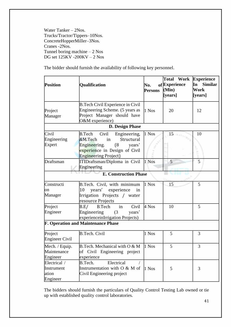
41
Water Tanker – 2Nos.
Trucks/Tractor/Tippers–10Nos.
ConcreteHopperMiller–3Nos.
Cranes -2Nos.
Tunnel boring machine – 2 Nos
DG set 125KV -200KV – 2 Nos
The bidder should furnish the availability of following key personnel.
Position
Qualification
No. of
Persons
Total Work
Experience
(Min)
[years]
Experience
In Similar
Work
[years]
Project
Manager
B.Tech Civil Experience in Civil
Engineering Scheme. (5 years as
Project Manager should have
O&M experience)
1 Nos
20
12
D. Design Phase
Civil
Engineering
Expert
B.Tech Civil Engineering, &M.Tech in Structural Engineering. (8 years’ experience in Design of Civil Engineering Project)
1 Nos 15 10
Draftsman ITIDraftsman/Diploma in Civil
Engineering
1 Nos 5 5
E. Construction Phase
Constructi
on
Manager
B.Tech. Civil, with minimum 10 years’ experience in Irrigation Projects / water resource Projects
1 Nos 15 5
Project
Engineer B.E/ B.Tech in Civil Engineering (3 years’
experienceinIrrigation Projects)
4 Nos 10 5
F. Operation and Maintenance Phase
Project
Engineer Civil
B.Tech. Civil 1 Nos 5 3
Mech. / Equip.
Maintenance
Engineer
B.Tech. Mechanical with O & M
of Civil Engineering project
experience
1 Nos 5 3
Electrical /
Instrument
ation
Engineer
B.Tech. Electrical /
Instrumentation with O & M of
Civil Engineering project
1 Nos
5
3
The bidders should furnish the particulars of Quality Control Testing Lab owned or tie
up with established quality control laboratories.
42
The bidder should furnish the Income Tax PAN and submission of Latest Income Tax
Return along with proof of receipt.
GST and other statutory taxes and duties will be adopted time to time as per the
instructions of Government of Kerala.
The Bidder should furnish the GST Registration Certificate, if not uploaded at the time
of tendering should be furnished at the time of agreement.
NOTE: The Internal Bench Mark [IBM] is arrived based on the probable quantities
indicated in the deliverables.
Cost ofTendering:
The bidder shall bear all cost associated with the preparation and submission of his tender
and the Employer will in no case be responsible or liable for these costs, regardless of the
conduct or outcome of the tendering procedure.
SiteVisit
The bidder is strongly advised to visit and examine the site of work and its surroundings.
He shall acquaint and obtain himself at his own responsibility all relevant information
such as existing utilities including underground services, availability of labour, basic
material, water, electricity etc., that may be necessary for preparation of the tender. A
declaration to this effect will have to be signed by the bidder in his tender.
Content of tendering documents
The tender document issued for the purpose of this tender is in two parts Technical Bid
and Financial Bid. Technical Bid contains Volume-I & Volume-II and Financial Bid is
in Volume-III.
Bidder is expected to examine carefully all instructions, conditions, terms, specifications
and drawings in the standard tender document viz. Technical Bid and Financial Bid,
Technical Bid contains Volume-I & Volume-II and Financial Bid is in Volume-III.
Failure to comply with the requirements of tender stipulations will be at the bidder’s risk.
Pursuant to clause 23 the tenders which are not responsive to the requirements of this
tender will be rejected.
Clarification of tender documents (Not used)
In case any clarification is required by the bidder, he may obtain it personally or in writing
well in advance from the Employer. Clarification for which written request has been
received at least 3 days prior to Pre-Bid meeting only will be answered.
Amendments to tenderdocument
At any time prior to the dead line for submission of tender, the employer may for any
reason whether at his own initiative or in response to a clarification requested by a
prospective bidder modify the tender document by issuance of an addendum. The
addendum will be kept in website www.kiidc.kerala.gov.in one week prior to date of
submission of bid.
Languageofthedocuments
The language of tender shall be English.
Documents comprising thetender
The tender to be prepared by the bidder shall comprise of the form of tender and
appendices thereto, the Bid Security, the information on technical man power to be
available on this work, the contractors alternative technical proposals based on scope of
work as defined in Volume II, design criteria, soil data and other such relevant
information and any other material required to be completed and submitted in accordance
with the instructions to bidders embodied in tender document. The forms and the data
provided in this document shall be used without exception.
The Technical Bid shall comprise of the following:
Scanned copy ofBid Security
43
Scanned copy of Registration
Scanned copy of Proof ofExperience
DataSheet-1– Bidder’s Appreciation of theProject
DataSheet-2– Bidder’s Organizational setup for theProject
DataSheet-3– Project Components along withDrawings
DataSheet-4– Management of Design and EngineeringServices
DataSheet-5– Construction Methodology of different componentsproposed
DataSheet-6– Proposed Deployment of Key Personnel
DataSheet-7– Proposed Deployment of ConstructionEquipment
DataSheet-8– Proposed Sub-Contractors
DataSheet-9– Proposed Source of KeyMaterials
Data Sheet-10 – Proposed Construction Schedule of theProject
Data Sheet-11– Quality Control and AssuranceSystem
Tender prices
11.1 The bidder shall quote his offer on form of tender Volume III as Lump sum at
appropriate place of the tender document to be submitted as per procedure set in clause
17. The Bidder shall quote further breakdown of Lump sum costs in Annexure– I,
Volume III. The bidder shall also quote unit prices in Annexure II, Volume – III.
Negotiations are not permitted at any stage in respect of price bid. The additions &
deductions will be worked out based on the Annexure – II.
11.2 The lump sum price quoted by the bidder shall include all the costs towards survey,
investigations, designing, execution, O&M and completing the works as predefined scope
of work and based on design criteria and Employers Requirement. The lumpsum offer
shall provide for all superintendence, labour, material, plant, equipment and all other
things required for work including all taxes, GST, duties, royalties and such other charges
except for the exceptions provided for in the contract.
In addition to L.S. Price the bidder are also to quote unit prices as an Annexure – I, II
and III which shall be reviewed and approved by the employer.
Tender validity
Validity of the tender will be 180 Days from the date fixed for opening of the tenders
and thereafter until it is withdrawn by notice in writing duly addressed to the authority
opening the tender.
13.1 The bidder shall furnish as a part of his tender Bid Security for Rs. 1, 58, 50,000/-
(Rupees One CroresandFifty Eight lakhs only).
13.2. The Bid Security to be furnished shall be/ Bank Guarantee in favourv of The
Managing Director, Kerala Irrigation Infrastructure Development Corporation
Limited, Thiruvananthapuram.
13.3. Any tender not accompanied by the Bid Security will stand rejected.
13.4. In the event of the tender being accepted subject to provisions of the subclause13.5
below, the said amount of bid Security, if so requested by the bidder be appropriated
towards the amount of performance Security deposit payable by him under the conditions
of contract.
13.5. “Forfeiture of Bid Security”: If after submitting the tender, the bidder withdraws
his offer or modifies the same or if after acceptance of his tender fails or neglects to furnish
the Performance Security, without prejudice to any rights and powers of the Employer
here under or in law, the employer shall be entitled to forfeit the full amount of Bid
Security deposited by the bidder. The employer shall also have right to forfeit the full
amount of Bid Security if the contractor fails to submit the performance guarantee (as per
clause 28.1) within 21 days from the receipt of LOA issued pursuant to clauseNo.27.
13.6. In the event of tender being not accepted the amount of Bid Security deposited by
44
the bidder, shall unless it is prior thereto to forfeit under provisions this contract, be
refunded to him on passing of receipt thereto without any interest.
13.7. Charges payable to:
Transaction Fee: It is mandatory for all the participating bidders to pay the
transaction fee at the time of bid submission.The amount is not
reimbursable.Transaction fee should be in the the form of Demand Draft of Rs. 10,000/- + GST, drawn in any Nationalized Bank and in favour of the Managing Director, Kerala Irrigation Infrastructure Development Corporation, Thiruvananthapuram. 13.8. Any bid not accompanied by both the Bid Security and Transaction fee will be
rejected by the employer as “non-responsive”.
13.9. The EPC contractor should abide to recover 10%of the each running account Bill.
Howeverthe max retention amount withheld is limited to 2.5% of the accepted amount of contract. No Variations in tendering conditions
The bidders are hereby instructed to not to alternate any changes in the bidding
documents. If any changes are made by bidder it shall be treated as tampering of
documents and the bid shall be summarily be rejected.
Pre-tender meeting
15.1. A pre-tender conference open to all prospective bidders will be held in the Office
of the Managing Director, Kerala Irrigation Infrastructure Development Corporation
Limited, Thiruvananthapuram wherein the prospective bidders will have an opportunity
to obtain clarifications regarding the tender conditions and the work. For this, only
questions received in writing 3 days prior to the pre-tender meeting shall be clarified in
writing.
15.2. The prospective bidders are free to ask any additional information or clarification
in writing and reply to the same will be given in writing. Minutes of the meeting including
copies of the questions raised and the replies given will be furnished to all those attending
the meeting (subsequently to all the bidders). Any modifications of tender document
which may become necessary as a result of pre tender conference shall be through
issuance of an addendum pursuant to clause 8&9 of these instructions.
Format and signing oftenders
16.1. The bidder shall prepare only one copy of the documents comprising the bid as
described in this document of these Instructions toBidders.
16.2. The bid shall be typed or written in indelible ink and shall be signed by a person or
persons duly authorized to sign on behalf of the bidder.
16.3 The bid shall contain no alterations, omissions or additions, except those to comply
with instructions issued by the Employer, or as necessary to correct errors made by the
bidder, in which case all such corrections shall be initialed by the person or persons
signing the bid.
16.4. All witnesses and sureties shall be persons of status and probity and their full names,
occupationsandaddressesshallbeprintedbelowtheirsignatures.
Submission oftenders
17.1 Bidders need to contact the General Manager, Kerala Irrigation Infrastructure
Development Corporation Limitedforinformationone-procurement.
17.2. The bidders may note the following
Furnishing of hard copies by the bidders before opening the technical bid is dispensed
with.
The technical bid evaluation of the bidders will be done on the certificates / documents
45
submitted towards qualification criteria furnished by the bidders.
The bidder shall invariably furnish the original BG for BID SECURITY, hard copies of
all documents to the Managing Director, Kerala Irrigation Infrastructure
Development Corporation Limited, before opening the price bids either personally or
through courier or by post and the receipt of the same within the stipulated time shall be
the responsibility of the bidder. Department will not take any responsibility for any delay
or non-receipt.
The bidders shall be required to furnish a declaration thatthe documents submittedby
them are genuine. Any incorrectness/ deviation noticed will be viewed seriously apart
from canceling the work duly forfeiting the BID SECURITY, criminal action will be
initiated including suspension of business.
vi) If any bidder fails to submit the original BG for BID SECURITY, transaction fee in
the prescribed form, hard copies of all documents within the stipulated time, the bidders
will be suspended / disqualified from participating in the tenders for a period of 36 months
from the date of bid submission. The suspension of bidder shall be automatically
enforced.
Tender opening
Tender will be opened manually and the venue will be decided by MD, KIIDC and the
bidders can joint physically or by video conferencing.
Process to be confidential
After opening of the tenders publicly information relating to the examination,
clarification, evaluation and comparison of tenders and recommendations concerning the
award of contract shall not be disclosed to the bidders or other persons not officially
concerned with such process until the award of the contract to successful bidder has been
announced.
Any effort by a bidder to influence the employer in process of examination clarification
evaluation comparison of bids and in decision concerning the award of contract may
result in rejection of tender.
Clarification of tenders
To assist in examination, evaluation of tenders the employer may ask bidders
individually, for clarification of their offer including break down of costs, reasons in case
of very high/very low offer. Such request shall be in writing and the response shall also
be in writing.
Tender liable for rejection
The tender is likely to be rejected if on opening it is found that –
The bidder has not strictly followed the procedure laid down for submission of tender.
The bidder has proposed conditions which are inconsistent with or contrary to the terms
and conditionsspecified.
Additions, correctionsoralteration are made by the bidder on any page of the tender
document.
Any page or pasted slips are missing.
The bidder has not signed the tender.
The bidder has specified any additional condition.
The bidder has not attached the addendum to the main tender form as stated in Para 7.
In case the technical proposal of bidder who has quoted lowest price and who has
satisfied other criteria is not conforming to the stipulations made, the bidder without
revising the cost shall modify the same to conform to the stipulations. If the bidder refuses
to modify thisthen the tender shall be treated as non-responsive and rejected.
The bidder has quoted financial offer any where other than specified in FinancialBid.

46
Correction of errors
If there is any discrepancy between the offer quoted in figures and in words, the rate
quoted in words will be treated as the offer.
Evaluation and comparison of tenders
Managing Director, Kerala Irrigation Infrastructure Development Corporation Limited
will evaluate whether each tenderer is satisfying the eligibility criteria prescribed in the
tender document and declares them as a qualified tenderer.
If the technical bid of a tenderer is not satisfying any of the eligibility criteria it will be
rejected by the Managing Director, Kerala Irrigation Infrastructure Development
Corporation Limited. However, the tender accepting authority detects any error in the
evaluation of tenders by Managing Director, Kerala Irrigation Infrastructure
Development Corporation Limited, the tender accepting authority while returning the
tenders may direct the Managing Director, Kerala Irrigation Infrastructure Development
Corporation Limited or Chief Engineer as the case may be, to re-evaluate the tenders.
If any alteration is made by the tenderer in the tender documents, the conditions of
thecontract, the drawings, specifications or statements / formats or quantities the
tenderwill be rejected.
Award criteria
Subject to clause 23, the employer will award the contract to a bidder whose tender has
been found to satisfy all requirements of tender document and who has offered the lowest
price.
Department’s right to accept any tender and to reject any or all tenders not with standing
the clause 24, the employer reserves the right to accept or reject any tender and to cancel
the tender process and reject all the tenders at any time prior to award of contract without
there by incurring any liability to the affected bidders or any obligation to inform affected
bidder/s of the grounds for employer’s action.
Notification of award.
Prior to the expiration of tender validity period or any such extended period, the employer
will notify the successful bidder in writing by a registered letter that his tender has been
accepted. This letter (herein after and in conditions of contract called letter of acceptance)
shall name the sum which the employer will pay to the Contractor in consideration of the
execution, completion and maintenance of the work by the Contractor as prescribed in
the Contract. This notification of award will constitute formation of contract.
Upon furnishing the performance Security by the successful bidder in accordance with
the clause 27 the order to start work will be given. The work order shall be accompanied
by a true copy of the agreement bearing the number under which it is registered in the
office of the Managing Director, Kerala Irrigation Infrastructure Development
Corporation Limited.
Performance guarantee
2.5%with a total of accepted tender amount / contract value as performance Security.
Fifty percentage (50%) of this amount should be in the form of Treasury Fixed deposit in
the name of Agreement Authority for a period not less than 28 (twenty-eight) days after
the completion of defect liability period and the remaining fifty percentage in the form of
bank guarantee or in any other forms prescribed in the revised PWD manual and shall be
valid till 28 (twenty-eight) days after the completion of defect liability period of the Work,
in any of the following forms. The balance fifty percentage (50%) of the performance
guarantee shall be either in the form of demand draft drawn in favour of the Managing
Director, Kerala Irrigation Infrastructure Development Corporation Limited or in the
form of bank guarantee issued by a Nationalized Banks of India or any scheduled Bank

47
in favour of the Managing Director, Kerala Irrigation Infrastructure Development
Corporation Limited. The Performance Security shall be valid until the Contractor has
fully and satisfactorily completed all of its obligations of the Contract.
Signing of agreement
Upon furnishing the Performance guarantee the contractor will be invited to conclude the
agreement.

48
Section 2: Conditions of Contract

49
SECTION - 2: CONDITIONS OF CONTRACT
A.GENERAL
Definitions:
The Employer is the Kerala Irrigation Infrastructure Development Corporation Limited
represented by the Managing Director.
Address
: Kerala Irrigation Infrastructure Development Corporation Limited (KIIDC],
PARVATHY, TC 36 /1, NH 66 Service Road,
Near EanchakkalJn, Chakkai P O,
Thiruvananthapuram -696024, Kerala
Email: [email protected]
The “Engineer” is Deputy General Manager or any authorized representative appointed
by the KIIDC
The following additional words and expressions shall have the meanings assigned to
them, except where the context otherwise required:
Authority or Department shall mean the successors in office and assigns.
The "Engineer-in-Chief" shall mean the Chief Engineer, KIIDC.
The "Superintending Engineer" shall mean the General Manager, Kerala Irrigation
Infrastructure Development Corporation Limited who is designated as such for the time
being, in whose jurisdiction the works lies.
The "Executive Engineer" shall mean the Deputy General Manager, Kerala Irrigation
Infrastructure Development Corporation Limitedwhois designated as such for the time
being, in whose jurisdiction the works lies.
The “Engineer” shall mean any authorized representative who appointed by the employer
to perform the duties and responsibilities of supervising the contract.
The “Engineer’s representative “means the project manager appointed / nominated by the
Engineer, who is consultant to the department to perform the duties and the
responsibilities of the engineer in supervising the contract.
A "Day" shall mean a day of 24 hours from midnight to midnight irrespective of the
number of hours worked in that day.
A “Week” shall mean 7 consecutive days without regard to the number of hours worked
in any day in that week.
The “Site” shall mean the lands and /or other places, on under, in or through which the
work is to be executed under the Contract including any other lands or places which may
be allotted by the Department or used for the purpose of Contract.
“Urgent Works” shall mean any measures which, in the opinion of Engineer becomes
necessary during the progress of the work to obviate any risk or accident or failure or
which becomes necessary for Securityoftheworkorthe persons working thereon.
Engineer’s Duties
The Engineer shall obtain the specific approval of the Employer in respect of the
following:
Approving sublettingoftheWork
Granting claims totheContractor
Ordering suspension of thework
Determining an extension oftime
Waiving off the penalty and arranging the repayment of compensationfordelay
50
Issuing of VariationOrder
Ordering any work/test beyond the scope of theContract
Determining rates for the extra items /extrawork
Any variations in the contractcondition
Approval to designs and working drawings
Duties of the Engineer’s Representative
The duties of the Engineer's Representative are to watch and supervise the work and to
test and examine any materials to be used or workmanship employed in connection with
theWorks
Interpretation:
In interpreting these Conditions of Contract, singular also means plural, male
alsomeansfemale, and vice-versa. Headings have no significance. Works have their
normal meaning under the language of the contract unless specifically defined. The
Engineers- in-charge will provide instructions clarifying queries about the conditions of
Contract.
The documents forming the Contract shall be interpreted in the following order of
priority:
ContractAgreement
Letter of Acceptance, notice to proceed with theworks
Contractor’s Tender (Technicalbid)
Conditions of contract (IncludingSpecialConditions)
Specifications
Drawings
Bill of quantities (Price-bid)
Any other document listed as forming part of theContract.
Engineer-in-Charge’sDecisions:
Except where otherwise specifically stated, the Engineer-in-charge will decide the
contractual matters between the KIIDCandtheContractor in the role representing the
Department / KIIDC.
Delegation:
3.1. The Engineer-in-charge may delegate any of his duties and responsibilities to other
officers and may cancel any delegation by an official orderissued.
Communications:
4.1. Communications between parties, which are referred to in the conditions, are
effective only when in writing. A notice shall be effective only when it is delivered (in
terms of Indian Contract Act)
Sub-contracting:
5.1. If the prime contractor desires to sub-let a part of the work, he should submit the
same at the time of filing tenders itself or during execution, giving the name of the
proposed Sub-contractor, along with details of his qualification and experience. The
Tender Accepting Authority should verify the experience of the Sub-contractor and if the
Sub- contractor satisfies the qualification criteria in proportion to the value of work
proposed to be sub-let, he may permit the same. The total value of works to be awarded
on sub-letting shall not exceed 50% of contract value. The extent of subletting shall be
added to the experience of the sub-contractor and to that extent deducted from that of the
main contractor. The Agency shall submit the names of their representatives who will be
supervising the work along with their photo ID card to the department within a month
from the date of entering into agreement. Further, in case of change in the personnel the
same shall be intimated tothedepartment, a week in advance. If other is found to be
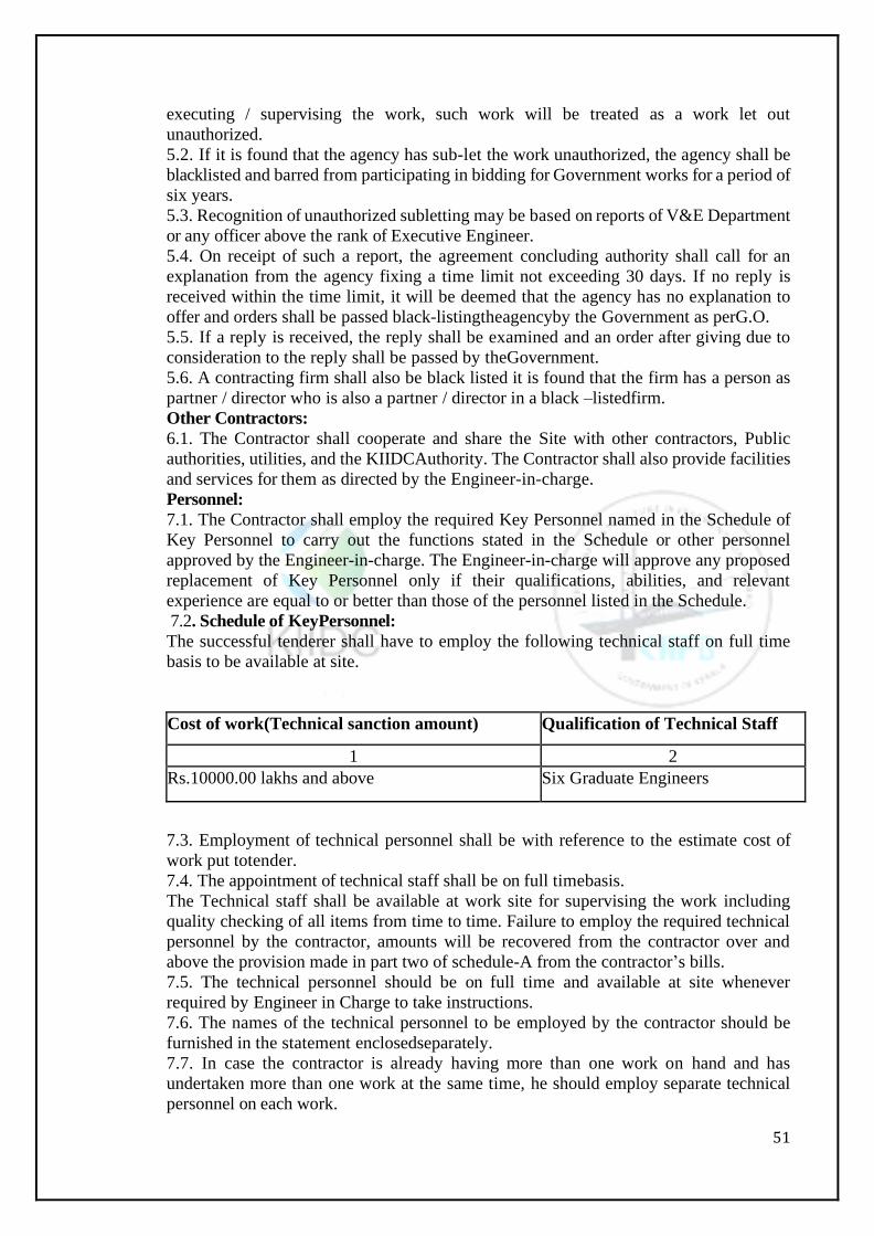
51
executing / supervising the work, such work will be treated as a work let out
unauthorized.
5.2. If it is found that the agency has sub-let the work unauthorized, the agency shall be
blacklisted and barred from participating in bidding for Government works for a period of
six years.
5.3. Recognition of unauthorized subletting may be based on reports of V&E Department
or any officer above the rank of Executive Engineer.
5.4. On receipt of such a report, the agreement concluding authority shall call for an
explanation from the agency fixing a time limit not exceeding 30 days. If no reply is
received within the time limit, it will be deemed that the agency has no explanation to
offer and orders shall be passed black-listingtheagencyby the Government as perG.O.
5.5. If a reply is received, the reply shall be examined and an order after giving due to
consideration to the reply shall be passed by theGovernment.
5.6. A contracting firm shall also be black listed it is found that the firm has a person as
partner / director who is also a partner / director in a black –listedfirm.
Other Contractors:
6.1. The Contractor shall cooperate and share the Site with other contractors, Public
authorities, utilities, and the KIIDCAuthority. The Contractor shall also provide facilities
and services for them as directed by the Engineer-in-charge.
Personnel:
7.1. The Contractor shall employ the required Key Personnel named in the Schedule of
Key Personnel to carry out the functions stated in the Schedule or other personnel
approved by the Engineer-in-charge. The Engineer-in-charge will approve any proposed
replacement of Key Personnel only if their qualifications, abilities, and relevant
experience are equal to or better than those of the personnel listed in the Schedule.
7.2. Schedule of KeyPersonnel:
The successful tenderer shall have to employ the following technical staff on full time
basis to be available at site.
Cost of work(Technical sanction amount) Qualification of Technical Staff
1 2
Rs.10000.00 lakhs and above Six Graduate Engineers
7.3. Employment of technical personnel shall be with reference to the estimate cost of
work put totender.
7.4. The appointment of technical staff shall be on full timebasis.
The Technical staff shall be available at work site for supervising the work including
quality checking of all items from time to time. Failure to employ the required technical
personnel by the contractor, amounts will be recovered from the contractor over and
above the provision made in part two of schedule-A from the contractor’s bills.
7.5. The technical personnel should be on full time and available at site whenever
required by Engineer in Charge to take instructions.
7.6. The names of the technical personnel to be employed by the contractor should be
furnished in the statement enclosedseparately.
7.7. In case the contractor is already having more than one work on hand and has
undertaken more than one work at the same time, he should employ separate technical
personnel on each work.
52
7.8. If the contractor fails to employ technical personnel the work will be suspended or
KIIDC will engage technical personnel and recover the cost thereof from thecontractor.
7.9. If the Engineer-in-charge / Employer / Employer’s Representative asks the
Contractor to remove a person who is a member of Contractor’s staff or his work force
stating the reasons the Contractor shall ensure that the person leaves the site forthwith
and has no further connection with the work in thecontract.
7.10. The Engineer-in-charge is the sole judgeto decide whether qualified technical staff
is actually supervising thework to decide the actual period of absence of such staff which
requires the above recovery to be enforced and his decision is final and binding on
thecontractor.
7.11. The technical agents appointed by the contractor shall have to maintain properly all
the records required by the KIIDCunder safe custody at site, like checklists, calibration
registers/records, Quality Test Registers, Test reports file, site order book, etc. and make
signatures at appropriate places towards proof of verifications, conduction of tests,
compliance to instructions etc.
7.12. Failure to employ the required technical personnel by the contractor the following
amounts will be recovered from the contractor over and above the provision made in
Schedule-B from the contractor’s bills.
7.13. The List of Key Personnel to be deployed on this project is mentioned in Annexure–
A. Contractor’s Risks: All risks of loss of or damage to physical property and of personnel injury and death,
which arise during and in consequence of the performance of the contract, are
theresponsibilityofthe contractor.
The Rate quoted is Final and Lump sum for the fulfillment of the entire project detailed earlier. Escalation or hike in prices of whatever kind will not be allowed later. Insurance:
9.1. Submission of insurance at the time of Concluding Agreement is dispensed forth
with.
9.2. The Contractor shall provide, in the name of the Department / KIIDC, insurance
cover for personal injury or death of persons employed for construction to the Managing
Director at the time of concluding agreement of thework.
9.3. The Contractor shall provide, in the joint names of the KIIDCandthecontractor,
insurance cover from the Start Date to the end of the Defects Liability Period i.e., 60
months after completion for the following events which are due to the Contractor’s risks.
a) Loss of or damage to the Works, Plant and Materials;
b) Loss of or damage to the Equipment;
c) Loss of or damage of property in connection with the Contract; and
d) Personalinjuryordeathofpersons employed for construction.
e) Professional liability Insurance: The Contractor shall affect professional indemnity
insurance, which shall covertheriskofprofessional negligence in the design of the works.
This insurance shall be for a limit of not less than Rs. 20.00 Lakh. The Contractor shall
use his best endeavor to maintain the professional indemnity insurance in full force and
effect until defect liability period. The Contractor undertakes to notify the Employer
promptly of any difficulty in extending, renewingorreinstatingthisinsurance.
9.4. Policies and certificates of insurance shall be delivered by the Contractor to the
Engineer-in-charge / Employer / Employer’s Representative at the time of concluding
Agreement. All such insurance shall provide for compensation to be payable to rectify
the loss or damageincurred.
i) The contractor shall furnish insurance policy in force in accordance with proposal
53
furnished in the Tender and approved by the KIIDCAuthority/ KIIDC for concluding the
agreement.
The contractor shall also pay regularly the subsequent insurance premium and produce
necessary receipt to the Engineer-in-Charge / Employer / Employer’s Representative,
well inadvance.
In case of failure to act in the above said manner the KIIDCAuthority/ KIIDC will pay
the premium and the same will be recovered from the Contractor’s payments.
9.5. Alterations to the terms of insurance shall not be made without the approval of the
Engineer-in-Charge/ Employer / Employer’sRepresentative.
Site Inspections:
10.1. The contractor should inspect the site and also proposed quarries of choice for
materials source of water and quote his percentage including quarrying, conveyance and
all other charges etc.
10.2. The responsibility for arranging the land for borrow area rests with the Contractor
and no separate payment will be made for procurement or otherwise. The contractor’s
quoted percentage will be inclusive of land cost.
Contractor to Constructthe Works:
11.1. The Contractor shall construct and Commission the Work in accordance with the
specifications andDrawings.
Diversion of streams / Vagus/Drains.
The contractor shall at all-time carry out construction of cross drainage works in a manner
creating least interference to the natural flow of water while consistent with the
satisfactory execution of work. A temporary diversion shall be formed by the contractor
at his cost where necessary. No extra payment shall be made for this work.
12.2 No separate payment for bailing out sub-soils, water drainage or locked up rain
waterfordiversion, shoring, foundations, bailing of pumping water either from excavation
of soils from foundations or such other incidental will be paid. The percentage to be
quotedby the contractor is for the finished item of work in situ and including all the
incidental charges. The borrow pits are also to be de-watered by the contractor himself
at his expense, if that should be found necessary.
12.3. The work of diversion arrangements should be carefully planned and prepared by
the contractor and forwarded to the MD, KIIDC, technically substantiating the proposals
and approval of the MD, KIIDC, obtained forexecution.
12.4. The contractor has to arrange for bailing out water, protection to the work in
progress and the portion of works already completed and safety measures for men and
materials and all necessary arrangements to complete thework.
12.5. All the arrangements so required should be carried outand maintained at the cost
of the contractor and no separate or additional payment isadmissible.
12.6. Coffer Dams
Necessary coffer dams and ring bunds have to be constructed at the cost of contractor and
same are to be removed after the completion of the work at the discretion of the
department
Power Supply.
13.1. The contractor shall make his own arrangements for obtaining power from the
Electricity dept., at his own cost. The contractor will pay the bills of Electricity for the
cost of power consumed byhim.
13.2. The contractor shall satisfy all the conditions and rules required as per Indian
Electricity Act 1910 and under Rule-45(I) of the Indian Electricity Rules, 1956 as
amended from time to time and other pertinentrules.
54
The power shall be used for bonafide Departmental/ KIIDC Authority workonly.
Temporary Diversions (Works on Highways / Municipal Roads)
14.1. The contractor shall at all-time carryout work on the highway in a manner creating
least interference to the flow of traffic while consistent with the satisfactory execution of
the same. For all works involving improvements to the existing highway, the contractor
shall in accordance with the directions of the Engineer-in-charge provide and maintain
during the execution of the work a passage for traffic, either along a part of the existing
carriage way under improvement or along a temporary diversion constructed close to the
highway.
14.2. If in the opinion of the Engineer-in-Charge/ Employer / Employer’s Representative,
it is not possible to pass the traffic on part width of the carriageway for any reason, a
temporary diversion close to the highway shall be constructed as directed. It shall be
paved with the materials such as hard morrum, gravel and stone, metal to the specified
thickness as directed by the Engineer-in-Charge / Employer / Employer’s Representative.
In all cases, the alignment, gradients and surface type of the diversion including its
junctions, shall be approved by the Engineer-in-charge/ Employer / Employer’s
Representative before the highway is closed totraffic.
14.3. The contractor shall take all necessary measures for the safety of traffic during
construction and provide erect and maintain such barricades, including signs, markings,
flags lights and information and protection of traffic approaching or passing through the
section of the highway under improvement. Before taking up any construction, an agreed
phased programme for the diversion of traffic on the highway shall be drawn up in
consultation with the Engineer-in-charge/Employer/Employer’sRepresentative.
14.4. The barricades erected on either side of the carriage way portion of the carriage way
closed to traffic, shall be of strong design to resist violation and painted with alternative
black andwhite stripe. Red lanterns or warnings lights of similar type shall be mounted
on the barricades at night and kept lit throughout from sunset tosunrise.
Ramps:
15.1. Ramps required during execution may be formed wherever necessary and same are
to be removed after completion of the work. No separate payment will be made for this
purpose.
Monsoon Damages:
16.1. Damages due to rain or flood either in cutting or in banks shall have to be made
good by the contractor till the work is handed over to the Department / KIIDC. The
responsibility of de-silting and making good the damages due to rain or flood rests with
the contractor. No extra payment is payable for such operations and the contractor shall
therefore, had to take all necessary precautions to protect the work done during the
construction period.
The works to be completed by the intended completion date:
17.1. The contractor may commence execution of the works on the start date and shall
carry out the works in accordance with the programmesubmitted by the contractor, as
updated with the approval of the Engineer-in-Charge / Employer / Employer’s
Representative, and complete the work by the Intended completion date.
Safety:
18.1. The Contractor shall be responsible for the safety of all activities onthesite.
Discoveries:
19.1. Anything of historical or other interest or of significant value unexpectedly
discovered ontheSite is the property of the Government / KIIDC. The Contractor is to
notify the Engineer-in-charge / Employer / Employer’s Representative of such
Representative instructions for dealing with them.
55
19.2. “Of the Applicants ranked as aforesaid, not more than 5 (five) shall be pre-qualified
andshort-listed for financial evaluation in the second stage. However, if the number of
such pre-qualified Applicants is less than two, the Authority may, in its sole discretion,
pre-qualify the Applicant(s) whose technical score is less than 60 (sixty) points even if
such Applicant(s)do(es) not qualify in terms of relevant clause, provided that in such an
event, the total number of pre-qualified and short-listed Applicants shall not exceed two”.
Possession of the Site.
20.1. The KIIDCshall give possession of the site to the Contractor. If discoveries and
carry out the Engineer-in-Charge’s / Employer / Employer’s possession of a part site is
given, the KIIDCwill ensure that the part
20.2. Additional land acquisition, if required, in few isolated stretches is foreseen in this
project. The Contractor shall submit relevant L.A. proposals as required and pursue with
the authorities concerned to acquire the land. The Department will assist the Contractor
in this regard and if any compensation has tobepaid, department will arrange to pay the
same. Site so handed over is amenable to carry out the work at site by the Contractor.
20.3. The Site for the execution of the work will be available as soon as the work is
awarded. In case it is not possible for the department to make entire site available on the
award of the work, due to any unforeseen reasons like court orders etc., the contractor
will have to modify his working programme accordingly. No claim whatsoever for not
giving the entire site in one stretch on award of work, (or) for handing over the site in
phases will be tenable.
Access to the Site:
21.1. The Contractor shall provide the Engineer-in-Charge / Employer / Employer’s
Representative and any person authorized by the Engineer-in-Charge, access to the site
and to any place where work in connection with the Contract is being carried out or is
intended to be carriedout.
Instructions:
22.1. The Contractor shall carry out all instructions of the Engineer-in-charge / Employer
/ Employer’s Representative and complies with all the applicable local laws where the
Site is located.
Site Order Book:
23.1. A site order book shall be maintained on the site and it shall be the property of the
Employer and the Contractor shall promptly sign orders given therein by the Engineer or
his authorized representative and comply with them. The compliance shall be reported by
Contractor to the Engineer in good time so that it can be checked. The blank site order
book with machine numbered pages in quadruplicate with perforated sheet for three
copies to be detached will be provided by the Engineer for this purpose. Whenever any
instructions are written in the site order book, the Contractor will be supplied the first
carbon copy.
Settlement of disputes:
24.1. If any dispute of difference of any kind whatsoever arises between the
KIIDCandtheContractor in connection with, or arising out of the Contract, whether
during the progress oftheworksorafter their completion and whether before or after the
termination, abandonment or breach of the Contract, it shall in the first place, be referred
to and settled by the Engineer-in-charge / Employer / Employer’s Representative who
shall, within a period of 30 (Thirty) days after being requested by the Contractor to do so,
give written notice of his decision to the Contractor. Upon receipt of the written notice of
the decision of the Engineer-in-Charge the Contractor shall promptly proceed without
56
delay to comply with such noticeofdecision.
24.2. If the Engineer-in-Charge / Employer / Employer’s Representative fails to give
notice of his decision in writing within a period of thirty days after being requested or if
the Contractor is dissatisfied with the notice of the decision of the Engineer-in-Charge/
Employer / Employer’s Representative, the Contractor may within thirty days after
receiving the notice of decision appeal to the KIIDCwho shall offer an opportunity to the
contractor to be heard and to offer evidence in support of his appeal, the KIIDCshall give
notice of his decision within a period of thirty days after the Contractor has given the said
evidence in support of his appeal, subject to arbitration, as hereinafter provided. Such
decision of theDepartment/ KIIDC in respect of every matter so referred shall be final and
binding upon the Contractor and shall forthwith be given effect to by the Contractor, who
shall proceed with the execution of the works with all due diligence whether he requires
arbitration as hereinafter provided, or not. If the KIIDChave given written notice of his
decision to the Contractor and no claim to arbitration, has been communicated to him by
the Contractor within a period of thirty days from receipt of such notice the said decision
shall remain final and binding upon the Contractor. If the KIIDCfail to give notice of his
decision, as aforesaid within a period of thirty days after being requested as aforesaid, or
if the Contractor be dissatisfied with any such decision, then and in any such case the
contractor within thirty days after the expiration of the first named period of thirty days
as the case may be, require that the matter or matters in dispute be referred to arbitration
as detailed below:
SETTLEMENT OF CLAIMS:
All claims to be settled by a Civil Court of competent jurisdiction by way of Civil suit
and not by arbitration.
A reference for adjudication under this clause shall be made by the contractor within six
months from the date of intimating the contractor of the preparation of final bill or his
having accepted payment whichever is earlier.
Arbitration shall not be a means of settlement of any dispute or claim out of this contract. All disputes and differences arising out of the contract may be resolved through discussions between the Employer and the Contractor within the purview of the contract agreement. If such discussions are not fruitful, the disputes shall be settled only by the Civil Court in whose jurisdiction the work covered by the contract is situated, or in whose jurisdiction the contract was entered into in case the work extended to the jurisdiction of more than one court. TIME FOR COMPLETION
Program:
25.1. The total period of completion is (as specified in the NIT) inclusive of Monsoon
Period from the date of entering with agreement toproceed including rainy season.
Keeping in view, the schedule for handing over of site given in condition below, the work
should be programmed such as to achieve the milestones as in “Rate of progress
statement” Mile Stones will be drawn by the agency which should be acceptable to the
Department.
25.2. The attention of the bidder is directed to the contract requirement at the time of
beginning of the work, the rate of progress and the dates for the whole work and its several
parts as per mile stone. The following rate of progress and proportionate value of work
done from time to time as will be indicated by the MD, KIIDC’s Certificate for the value
of work done will be required. Date of commencementoftheir programme will be the date
for concluding agreement but not the date of handing over site.
25.3. After signing the agreement, the contractor shall forthwith begin the work,
57
shallregularlyand continuously proceed with them.
25.4. Rate of progress:
Work programme of achieving themilestones (Statement).
The contractor/EPC agency shall be subject to the following Key activities to carry out
its operations as indicated below during design, construction and operation period of 5
years including “Defect Liability Period” (5years).
Sl.
No.
Sectional Milestone
Time from
stipulated date of
contract
start(days)
Event of
start
Activities
1 Mobilization 15 Contract
signing
Irrigation works:
2 Completion of allSurvey,
investigation work.
Submission of Quality
assurance plan
45
Contract
signing
Including all
surveys, QAP
3 Submission of Systematic
investment plan (SIP)
60 Contract
signing
Including Designs,BOQ,
implementation and
phasing program and
methodology
4 Approval of SIP 60 Contract
signing
5 Supply, fabricating and
laying and erecting MS
pipe, lift Irrigation
scheme, renovation of
pond, soil investigation.
730
Contract
signing
Implementation of
the project.
Site schedule of programmeofhanding over site to the contractor site will be handed over
to the contractor in stages according to the progress of work. (Statement)
The contractor shall achieve the financial progress; otherwise, Liquidated Damages shall
be levied as per the conditions ofcontract.
25.5. The contractor shall commence the works on site within the period specified under
condition 24.1 to 24.3 above after the receipt by him of a written order to this effect from
the MD, KIIDC and shall proceed with the same with due expedition and without delay,
except as may be expressly sanctioned or ordered by the Managing Director, Kerala
Irrigation Infrastructure Development Corporation Limited, Thiruvananthapuram, or be
wholly beyond the contractor’s control.
25.6. Save in so far as the contractor may prescribe, the extent of portions of the site of
which the contractor is to be given possession from time to time and the order in which
such portions shall be made available to him and, Subject to any requirement in the
contract as to the order in which the works shall be executed, the Deputy General
Manager will, with the MD, KIIDC ’s written order to commence the works, give to the

58
contractor possession of so much of the site as may be required to enable the contractor
to commence proceed with the execution of the works in accordance with the programme
if any, and otherwise in accordance with such reasonable proposals of the contractor as
he shall by written notice to the Managing Director, Kerala Irrigation Infrastructure
Development Corporation Limited, Thiruvananthapuram, make and will from time to
time as the works proceed, give to the contractor possession of such further portions of
the site as may be required to enable the contractor to proceed with the execution of the
works with due dispatch in accordance with the said programmeorproposals as the case
maybe ; if the contractor suffers delay or incurs cost from failure on the part of the
Managing Director, Kerala Irrigation Infrastructure Development Corporation Limited,
Thiruvananthapuram, to give possession in accordance with the terms of this clause, the
Managing Director, Kerala Irrigation Infrastructure Development Corporation Limited,
Thiruvananthapuram, shall grant an extension of time for the completion of works.
25.7. The contractor shall bear all costs and charges for special or temporary way leases
required by him in connection with access to the site. The contractor shall also provide
at his own cost any additional accommodation outside the site required by him for the
purposes of the work.
25.8. Subject to any requirement in the contract as to completion of any section of the
works before completion of the whole of the works shall be completed in accordance with
provisions of clauses in the Schedule within the time stated in the contract calculated
from the last day of the period named in the statement to the tender as that within which
the works are tobecommencedorsuch extended time as may be allowed.
25.9. Delays and extension oftime:
No claim for compensation on account of delays or hindrances to the work from any
causes whatever shall lie, except as hereafter defined. Reasonable extension of time will
be allowed by the officer competent to sanction the extension, for unavoidable delays,
such as may result from causes, which in the opinion of the Managing Director, Kerala
Irrigation Infrastructure Development Corporation Limited, Thiruvananthapuram, and
are undoubtedly beyond the control of the contract. The Managing Director, Kerala
Irrigation Infrastructure Development Corporation Limited, Thiruvananthapuram shall
assess the period of delay or hindrance caused by any written instructions issued by him,
at twenty five percent in excess or the actual working period solost.
In the event of the Deputy General Manager failing to issue necessary instructions and
thereby causing delay and hindrance to the contractor, the latter shall have the right to
claim an assessment of such delay by the Managing Director, Kerala Irrigation
Infrastructure Development Corporation Limited, Thiruvananthapuram, whose decision
will be final and binding. The contractor shall lodge in writing with the Deputy General
Manager a statement of claim for any delay or hindrance referred to above, within
fourteen days from its commencement, otherwise no extension of time will be allowed.
Whenever authorized alterations or additions made during the progress of the work are of
such a nature in the opinion of the Managing Director, Kerala Irrigation Infrastructure
Development Corporation Limited, Thiruvananthapuram, as to justify an extension of
time in consequence thereof. If there are valid reasons for extending the contract period,
proposals for extension of time should be sent to the authority competent to accord
administrative sanction, sufficiently in advance and in any case at least one month before
the expiry of the contract period.
ConstructionProgramme:
26.1. The Contractor shall furnish within 15 days from the receipt of work order, the work
programme showing the sequence in which he proposed to carry out the work, monthly
progress expected to be achieved, also indicating date of procurement
59
ofmaterialsplantand machinery. The schedule should be such that it is practicable to
achieve completion of the whole work within the time limit fixed and in keeping with the
Mile stone programme specified and shall obtain the approval of the Engineer-in-Charge/
Employer / Employer’s Representative. Further rate of the progress as in the program
shall be kept up to date. In case it is subsequently found necessary to alter this program,
the contractor shall submit sufficiently in advance the revised program incorporating
necessary modifications and get the same approved by the Engineer - in - Charge. No
revised program shall be operative without approval of Engineer-in–Charge.
26.2. The Managing Director, Kerala Irrigation Infrastructure Development Corporation
Limited, Thiruvananthapuram shall have all times the right, without any way violating
this contract, or forming grounds for any claim, to alter the order of progress of the works
or any part thereof and he contractor shall after receiving such directions proceed in the
order directed. The contractor shall also report the progress to the Managing Director,
Kerala Irrigation Infrastructure Development Corporation Limited, Thiruvananthapuram,
within 7 days of the Executive Engineers direction to alter the order of progress ofworks.
26.3. The contractor shall give written notice to the Engineer-in-Charge/ Employer /
Employer’s Representative whenever planning or progress of the works is likely to be
delayed on disrupted unless any further drawings or order including a direction,
instruction or approval is issued by the Engineer-in-Charge/ Employer / Employer’s
Representative within areasonable time. The notice shall include details of the drawing
or order required and of why and by when it is required and of any delay or disruption
likely to be suffered if it islate.
Speed of Work
27.1. The Contractor shall at all timesmaintainthe progress of work to conform to the
latest operative progress schedule approved by the Engineer-in-Charge/
Employer/Employer’s Representative. The contractor should furnish progress report
indicating the programme and progress once in a month. The Engineer-in-Charge/
Employer / Employer’s Representative may at any time in writing direct the contractor
to slow down any part or whole of the work for any reason (which shall not be questioned)
whatsoever, and the contractor shall comply with such orders of the Engineer-in- Charge/
Employer / Employer’s Representative. The compliance of such orders shall not entitle
the contractor to any claim of compensation. Such orders of the Engineer-in- Charge/
Employer / Employer’s Representative for slowing down the work will however be duly
taken into account while granting extension of time if asked by the contractor for which
no extra payment will beentertained.
27.2. Delays in Commencement or progress or neglect of work and forfeiture
ofearnestmoney, Security deposit and withheldamounts:
If, at any time, the Engineer-in-Charge/ Employer / Employer’s Representative shall be
of the opinion that the contractor is delaying commencement of the work or violating any
of the provisions of the contractor is neglecting or delaying the progress of the work as
defined by the tabular statement. “Rate of progress” in the “Articles of Agreement”, he
shall so advise the contractor in writing and at the same time demand compliance in
accordance with conditions of Tender Notice. If the contractor neglects to comply with
such demand within seven days after receipt of notice, it shall then or at any time
thereafter, be lawful for the Engineer-in-Charge/ Employer / Employer’s Representative
to take suitable action in accordance with Provisionsof MDSS
Suspension of works by theContractor.
28.1. If the Contractor shall suspend the works, or sublet the work without sanction of the
Engineer-in-Charge/ Employer / Employer’s Representative, or in the opinion of the
Engineer-in-Charge/ Employer / Employer’s Representative shall neglect or fail to
60
proceed with due diligence in the performance of his part of the Contract as laid down in
the Schedule rate of progress, or if he shall continue to default or repeat such default in
the respects mentioned in Provisions of the MDSS, Engineer - in - Charge shall take action
in accordance with provisions of MDSS..
28.2. If the Contractor stops work for 28 days and the Stoppage has not been authorizedby
the Engineer - in - Charge the Contract will be terminated under Provisions of MDSS
28.3. If the Contractor has delayed the completion of works the Contract will be
terminated under Provisions of MDSS.
29. Extension of the Intended Completion Date:
29.1. The Engineer - in - Charge shall extend or recommend for extension, in accordance
with the Government / KIIDC Authority’s orders in force, the Intended Completion Date
if a Variation is issued which makes it impossible for Completion to be achieved by the
Intended CompletionDate.
29.2. The Engineer-in-Charge/ Employer / Employer’s Representative shall decide
whether and by how much to extend the Intended Completion Date within 21 days of the
Contractor asking the Engineer for a decision upon the effect of a Variation and
submitting full supporting information.If the Contractor has failed to give early warning
of a delay or has failed to cooperate in dealing with a delay, the delay by this failure shall
not be considered in assessing the new Intended CompletionDate.
30. Delays Ordered by the Engineer-in-Charge/ Employer /Employer’s Representative:
30.1. The Engineer-In-Charge / Employer / Employer’s Representative may instruct the
Contractor to delay the start or progress of any activity within theWork.
Early Warning:
31.1. The contractor is to warn the Engineer-In-Charge / Employer / Employer’s
Representative at the earliest opportunity of specific likely future events or circumstances
that may adversely affect the execution ofworks.
31.2. The Contractor shall cooperate with the Engineer-In-Charge / Employer /
Employer’s Representative in making and considering proposals for how the effect of
such an event or circumstance can be avoided or reduced by anyone involved in the work
and in carrying out any resulting instruction of the Engineer-In-Charge/ Employer /
Employer’sRepresentative.
Management Meetings:
32.1. The Engineer-In-Charge / Employer / Employer’s Representative may require the
Contractor to attend a management meeting. The business of a management meeting shall
be to review the programmeforremainingworkand to deal with matters raised in
accordance with the early warning procedure.
QUALITYCONTROL
Identifying Defects:
33.1. The Engineer-in-Charge/ Employer/ Employer’s Representative/ Project
Management Consultant engaged by the client shall check the Contractor’s work and
notify the Contractor of any Defects that are found. Such checking shall not affect the
Contractor’s responsibilities. The Engineer-in-Charge/ Employer / Employer’s
Representative may instruct the Contractor to verify the Defect and to uncover and test
any work that the Engineer considers may be a Defect.
Tests:
34.1. Laboratory fortesting:
The contractor shall for the purpose of testing the material shall establish a field
61
laboratory of 40 sq. meter area. The contractor shall provide all equipment as per list in
Annexure - D.
34.2. If the Engineer-In-Charge/ Employer / Employer’s Representative instructs the
contractor to carry out a test not specified in the specification to check whether any work
has a defect and the contractor shall pay for the test and any samples.
Correction of Defects:
35.1. The Engineer-In-Charge / Employer / Employer’s Representative shall give notice
to the contractor of any defects before the end of the defectsliabilityperiod, which begins
on completion. The defects liability period shall be extended for as long as defects remain
to be corrected by the contractor.
35.2. Every time notice of a defect when given, the contractor shall correct the notified
defect within the length of time specified by the Engineer-In-Charge’s / Employer /
Employer’s Representativenotice.
Uncorrecteddefects
36.1. If the contractor has not corrected the defect within the time specified in the
Engineer- in-Charge/ Employer / Employer’s Representative’s notice, the Engineer-in-
Charge/ Employer / Employer’s Representative will assess the cost of having the defect
corrected and the contractor will pay thisamount.
36.2. The Engineer-In-Charge / Employer / Employer’s Representative shall introduce
O.K cards and prescribed the formats there of. O.K cards shall relate to all major
components of the work. The contractor/his authorized representative shall be required
to initiate and fill in and present the O.K card to the construction staff that would check
the respective items and send to the quality control staff for final check and
clearance/O.K. Any defects pointed out by the construction supervision staff or by the
Quality Control staff shall promptly be attended to by the contractors and the fact of
doing so be duly recorded on the back of O.K Card.
36.3. The Engineer-In-Charge / Employer / Employer’s Representative may also
introduce check lists which shall be kept in Bound registers by the construction
supervision staff. The contractor may be required to fill up these lists in the first instance
and shall be subsequently checked by the Construction / Quality Control Engineers.
Quality Control:
37.1. In addition to the normal inspection by the regular staff in-charge of the construction
of work, the work will also be inspected by the Executive Engineer/Superintending
Engineer /Chief Engineer Quality control Circle or by the State or District level Vigilance
Cell Unit and any other authorized external Agency if any sub-standard work or excess
payments are noticed with reference to measurement books etc., during inspection, action
will be taken based on their observations and these will be effected by the Engineer-in-
Charge/ Employer / Employer’s Representative of the execution of the work.
For all works costing more than Rs.2.00 Crores the Contractor shall submit quality plan
and also show proof of owning quality lab or tie-up with an established quality lab.
COST CONTROL
Lump Sum Price:
38.1. The Contractor is paid for the quantity of the work done on prorate basis against
each item as per Annexure-I, Volume-III.
38.2. Variations in Scope of Work: It shall be generally understood that the price quoted
by the tenderer shall be all inclusive price for completion of scope of work detailed in the
tender document and is for finished work at site in all respects including minor

62
modifications where felt essential.
In an unlikely event, should the exigencies of work so demand that any major
modifications are found essential in any component of the works, the payment for the
corresponding variations shall be regulated as per Annexure II &III of Volume III. The
variations, not covered by Annexure II & III, rates of DSR 2019 will be applied
38.3.The extra items:
38.3.1. In case of contingent items, approval shall be accorded by General Manager,
Kerala Irrigation Infrastructure Development Corporation Limited.
38.3.2. Non-contingent shall be approved by the committee constituted for the purpose.
38.3.3. Contingent but outside the scope of the original contract shall be approved by the
committee constituted for this purpose.
Changes in the Scope:
39.1. The contractor is bound to execute all supplemental works that are found essential,
incidental and inevitable during execution of main work.
Extra Items:
40.1. Extra items of work shall not vitiate the contract. The contractor shall be bound to
execute extra items of work as directed by the Engineer - in – Charge. The rates for extra
items shall be worked out by the Executive Engineer as per the conditions of the Contract
and the same are binding on the Contractor.
40.2. The contractor shall before the 15thday of each month, submit in writing to the
Executive Engineer a statement of extra items if any that they have executed during the
preceding month failing which the contractor shall not be entitled to claim any.
40.3. Entrustment of additional items:
40.3.1. Where ever additional items not contingent on the main work and outside the
scope of original agreement are to be entrusted to the original contractor dispensing with
bids and if the value of such items exceeds the limits up to which the officer is empowered
to entrust works initially to contractor without calling for tenders, approval of next higher
authority shall be obtained. Entrustment of such items on nomination shall be at rates
not exceeding the estimated rates.
40.3.2. Payment for the additional scope of work executed shall be decided based upon
the following:
* Unit rates quoted and duly agreed by the Department.
* DSR 2016
Cash flow forecasts:
41.1. When the program is updated, the contractor is to provide the Engineer-in-Charge/
Employer / Employer’s Representative with an updated cash flow forecast.
41.2. The contractor shall also provide to the Engineer-in-Charge/ Employer /
Employer's Representative with a WBS (Work Brakedown Structure) in Micro Soft
Project MSP which is to be updated periodically.
Payment Certificates:
42.1. The Contractor shall submit to the Engineer-In-Charge / Employer / Employer’s
Representative monthly statements of the estimated value of the work completed less the
cumulative amount certified previously.
42.2. The Engineer-In-Charge / Employer / Employer’s Representative shall check the
Contractor’s monthly statement within 14days.
42.3. The value of work executed shall be determined by the Engineer-In-Charge/
Employer/ Employer’s Representative.
42.4. The Engineer-In-Charge / Employer / Employer’s Representative mayexclude any
item certified in a previous certificate or reduce the proportionof any item previously
63
certified in any certificate in the light of later information.
Payments:
43.1. EPC Contractor’s Application for Payment:
43.1.1.The EPC contractor shall abide the norms and guidlines stipulated by KIIFB, from
time to time for Payment of Bill.
43.1.2 On the fifth Business Day of every month from the date of issue of the Notice to
Proceed the EPC Contractor may serve a notice in writing on the Employer’s
Representative (Request for Payment) requesting payment of the sum which is considers
being due on achievement of milestones as per the Annexure –I, Volume - 03. (Milestone
Payment), less the amount to be deducted as RetentionMoney
Advance payment in proportionate amounts commencing upon the submissions by the
EPC Contractor of the Request for Payment for the fourth monthly period after the date
of issue of the Notice to proceed and ending upon the date of the last Request for payment;
and
(c) Any amounts due and owing from the EPC Contractor to the Employer pursuant to
thisAgreement.
43.1.3. The Request for Payment shall be:
(a)Prepared on forms in the form indicated by the Employer’s representative and at the
expense of the EPC Contractor, the number of copies therefore shall be as the Employer’s
Representative may determine;and
(b)Accompanied by such supporting documentation as the Employer’s Representative
may require to establish the value of the work property designed and Executed as referred
to in the Request for payment and reasonableness of the amounts added in respect of
goods andmaterials.
43.2.Certificates of Payment
43.2.1 Within fourteen (14) Business Days after the receipt of the Request for payment,
the Employer’s Representative shall, subject to the EPC Contractor’s compliance
withArticle43.2inspect the relevant parts of the Works and the relevant goods and
materials in order to satisfy him that the request for payment is correct.
If the Employer’s Representative is so satisfied, he shall issue a Certificate of Payment
certifying what amounts are due to the EPC Contractor pursuant to this Article 43 subject
to the provisions of Article 43.2.2 to 43.2.3 after giving credit to the Employer for any
sums to which the Employer is entitled under this Agreement.
43.2.2. No sum shall be included in the Certificate of Payment in respect of goods and
materials yet to be incorporated into the payment works unless the employers’
Representative is satisfied and has approved in writingthat:
(a) Such goods and materials have been properly acquired and properly and not
prematurely delivered to the ProjectSite;
(b) Such goods plant and materials are properly stored on the project site; and fully
protected against loss, damage ordeterioration;
(c) The EPC Contractor’s records of the requisitions, orders, receipts and use of any goods
and materials are kept in a form approved by the Employer’s Representative, and such
records are available for inspection by the Employer’s Representative;and
(d) The EPC Contractor has submitted a proper statement of the cost of acquiring the
goods and materials together with such documents as may be required for evidencing
suchcost.
43.2.3. In the event that the Employer’s Representative ascertains that the value of the
works properly designed and Executed in the relevant period is less than the Milestone
Payment for the period, he shall include in the Certificate of payment, the value of the
64
works and goods and materials so ascertained by him.
43.2.4. All Certificates of Payment shall specify the amount, which the Employer
proposes to pay to the EPC Contractor and the basis on which that amount was calculated.
Such amount shall become due on the issue of the said Certificate of Payment.
43.2.5. 5% of the interim payment certificate shall bepaid within 7 days & balance shall
be paid within 14 days of receipt from theEngineer.
43.2.6. The final payment certificate (statement at completion) shall be paid within 84
days of receipt from the Engineer.
Certificate of Completion of works:
44.1. Certificate of Completion of works:
44.1.1. When the whole of the work has been completed and has satisfactory passed any
final test that may be prescribed by the Contract, the Contractor may give a notice to that
effect to the Engineer-in-Charge/ Employer / Employer’s Representative accompanied
by an undertaking to carry out any rectification work during the period of maintenance,
such notice and undertaking shall be in writing and shall be deemed to be request by the
Contractor for the Engineer-in-Charge/ Employer / Employer’s Representative to issue a
Certificate of completion in respect of the Works.
The Engineer-in-Charge/ Employer / Employer’s Representative shall, within twenty one
days of the date of delivery of such notice either issue to the Contractor, a certificate of
completion stating the date on which, in his opinion, the works were completed in
accordance with the Contract or give instructions in writing to the Contractor specifying
all the Works which, in the Engineer-in-Charge/ Employer / Employer’s Representative'’
opinion, required to be done by the Contractor before the issue of such Certificate. The
Engineer-in-Charge/ Employer / Employer’s Representative shall also notify the
Contractor of any defects in the Works affecting completion that may appear after such
instructions and before completion of the Works specified there in. The Contractor shall
be entitled to receive such Certificate of the Completion within twenty one days of
completion to the satisfaction of the Engineer-in-Charge/ Employer / Employer’s
Representative of the Works so specified and making good of any defects so notified.
44.1.2. Similarly, the Contractor may requestandthe Engineer-in-Charge/ Employer /
Employer’s Representative shall issue a Certificate of Completion in respect of:
(a) Any section of the permanent works in respect of which a separate time for completion
is provided in the Contract and
(b) Any substantial part of the permanent works which has been both completed to the
satisfaction of the Engineer-in-Charge/ Employer / Employer’s Representative and
occupied or used by the KIIDCAuthority.
44.1.3. If any part of the Permanent Works shall have been completed and shall have
satisfactorily passed any final test that may be prescribed by the Contract, the Engineer-
in-Charge/ Employer / Employer’s Representative may issue such certificate, and the
Contractor shall be deemed to have undertaken to complete any outstanding work in that
part of the Works during the period of Maintenance.
Taxes
45.1. The percentage quoted by the contractor shall be inclusive of Goods and Service
Tax (GST) and other statutory taxes on all materials that the contractor will have to
purchase for performance of this contract.
45.2. All Taxes such as GST, seignorage, royalties, tools, control, etc., in respect of
materials to be consumed on the work and also in the finished item of work etc., must be
borne by the contractors.
45.3Interest on Money due to the Contractor:
45.3.1No omission by the Deputy General Manager or the sub-divisional officer to pay
65
the amount due upon certificates shall vitiate or make void the contract, nor shall the
contractor be entitled to interest upon any guarantee fund or payments in arrears, nor upon
any balance which may, on the final settlement of his accounts, found to be due to him.
45.4. Income Tax:
45.4.1.As per section 194-C of income tax act 1961, deduction at the rate of 2.24% in
respect of individual contractors and 2.30% in respect of firms on the gross amounts of
payments will be made towards income tax. The tax will be recovered at the rates as per
the income tax act during course of execution.
45.4.2. The income tax will be deducted as per rules in force fromthecontractorbills
45.4.3. Income Tax clearance certificate should be furnished before the payment of final
Bill.
45.4.4. The contractor’s staff, personal and labour will be liable to pay personnel income
taxes in respect of their salaries and wages as are chargeable underthe Laws and
regulations for the time being in force and the contractor shall perform such duties in
regard to such deductions there of as may be imposed on him by such laws and
regulations.
Seignorage Charges
45.5.1 Seignoragecharges will be recovered as perrules
45.5.2 The Seignorage charges will be recovered from the contractors bills as per rules
or as per the rates fixed by the Mines & Geology Department from time to time as on
Date of recording measurements in measurement books whichever is higher for the
materials consumed theoretically on the workonly.
45.6. GST/VAT:
45.6.1. GST/VAT on Running Bills will be recovered as per rules
PriceAdjustment:
46.1.1 Price adjustment for steel, cement, bitumen, POL and other pipe materials is applicable
as per Government Orders inforceand issued from time totime.
TERMS OFPAYMENT
The payment will be made to the contractor as per the prevailing norms and rules of
KIIFB. PaymentSchedule to be approved by EPC Committee:
The Payment Terms are given in Volume IV
Note: The EPC agency shall furnish the detailed estimates, BoQs based on approved
drawings as per provisions of the Deliverables. The above payment schedule can be sub
divided into various sub-components with appropriate percentage break up as per the
estimate &BoQs approved by the Departmental authorities but within the overall
percentage break up of each component as approved by EPC Committee-I.
Retention
48.1. The KIIDCshall retain from each payment duetothecontractor@ the rate of 10
%ofbillamount until completion of the whole of theWorks.
48.2. On completion of the whole of the Works half (5%)ofthetotal amount retained
including 2.5% Performance Guaranteeisre-paid to the Contractor and balance half (5%)
when the Defects Liability Period has passed and the Employer/ Employer’s
representative has certified that all the Defects notified by the Employer/ Employer’s
representative to the Contractor before the end of this period have beencorrected.
48.3. On completion of the Defects Liability Period half (5%) of the total amount retained
including 2.5% Performance Guarantee is re-paid to the Contractor and the Employer/
Employer’s representative has certified that all the Defects notified by the Employer/
Employer’s representative to the Contractor before the end of this period have been
corrected. While the balance half (5%) shall be paid on completion of O&Mperiod.
48.4. On completion of the whole works, the Contractor may substitute retention money
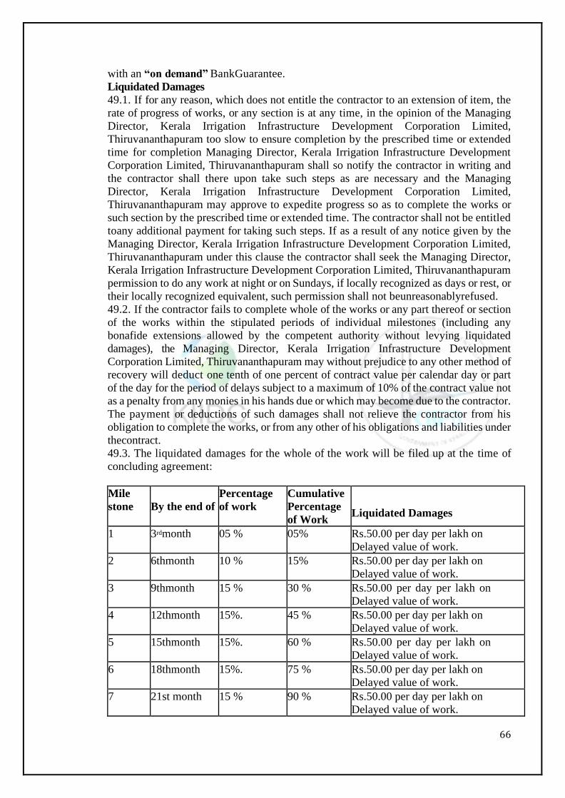
66
with an “on demand” BankGuarantee.
Liquidated Damages
49.1. If for any reason, which does not entitle the contractor to an extension of item, the
rate of progress of works, or any section is at any time, in the opinion of the Managing
Director, Kerala Irrigation Infrastructure Development Corporation Limited,
Thiruvananthapuram too slow to ensure completion by the prescribed time or extended
time for completion Managing Director, Kerala Irrigation Infrastructure Development
Corporation Limited, Thiruvananthapuram shall so notify the contractor in writing and
the contractor shall there upon take such steps as are necessary and the Managing
Director, Kerala Irrigation Infrastructure Development Corporation Limited,
Thiruvananthapuram may approve to expedite progress so as to complete the works or
such section by the prescribed time or extended time. The contractor shall not be entitled
toany additional payment for taking such steps. If as a result of any notice given by the
Managing Director, Kerala Irrigation Infrastructure Development Corporation Limited,
Thiruvananthapuram under this clause the contractor shall seek the Managing Director,
Kerala Irrigation Infrastructure Development Corporation Limited, Thiruvananthapuram
permission to do any work at night or on Sundays, if locally recognized as days or rest, or
their locally recognized equivalent, such permission shall not beunreasonablyrefused.
49.2. If the contractor fails to complete whole of the works or any part thereof or section
of the works within the stipulated periods of individual milestones (including any
bonafide extensions allowed by the competent authority without levying liquidated
damages), the Managing Director, Kerala Irrigation Infrastructure Development
Corporation Limited, Thiruvananthapuram may without prejudice to any other method of
recovery will deduct one tenth of one percent of contract value per calendar day or part
of the day for the period of delays subject to a maximum of 10% of the contract value not
as a penalty from any monies in his hands due or which may become due to the contractor.
The payment or deductions of such damages shall not relieve the contractor from his
obligation to complete the works, or from any other of his obligations and liabilities under
thecontract.
49.3. The liquidated damages for the whole of the work will be filed up at the time of
concluding agreement:
Mile
stone By the end of
Percentage
of work
Cumulative
Percentage
of Work
Liquidated Damages
1 3rdmonth 05 % 05% Rs.50.00 per day per lakh on
Delayed value of work.
2 6thmonth 10 % 15% Rs.50.00 per day per lakh on
Delayed value of work.
3 9thmonth 15 % 30 % Rs.50.00 per day per lakh on
Delayed value of work.
4 12thmonth 15%. 45 % Rs.50.00 per day per lakh on
Delayed value of work.
5 15thmonth 15%. 60 % Rs.50.00 per day per lakh on
Delayed value of work.
6 18thmonth 15%. 75 % Rs.50.00 per day per lakh on
Delayed value of work.
7 21st month 15 % 90 % Rs.50.00 per day per lakh on
Delayed value of work.
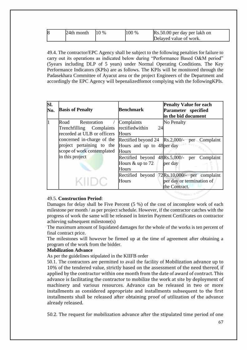
67
8 24th month 10 % 100 % Rs.50.00 per day per lakh on
Delayed value of work.
49.4. The contractor/EPC Agency shall be subject to the following penalties for failure to
carry out its operations as indicated below during “Performance Based O&M period”
(5years including DLP of 5 years) under Normal Operating Conditions. The Key
Performance Indicators (KPIs) are as follows. The KPIs will be monitored through the
Padasekhara Committee of Ayacut area or the project Engineers of the Department and
accordingly the EPC Agency will bepenalizedfornot complying with the followingKPIs.
Sl.
No.
Basis of Penalty
Benchmark Penalty Value for each
Parameter specified
in the bid document
1 Road Restoration /
Trenchfilling Complaints
recorded at ULB or officers
concerned in-charge of the
project pertaining to the
scope of work contemplated
in this project
Complaints
rectifiedwithin 24
Hours
No Penalty
Rectified beyond 24
Hours and up to 48
Hours
Rs.2,000/- per Complaint
per day
Rectified beyond 48
Hours & up to 72
Hours
Rs.5,000/- per Complaint
per day
Rectified beyond 72
Hours
Rs.10,000/- per complaint
per day or termination of
the Contract.
49.5. Construction Period:
Damages for delay shall be Five Percent (5 %) of the cost of incomplete work of each
milestone per month / as per project schedule. However, if the contractor catches with the
progress of work the same will be released in Interim Payment Certificates on contractor
achieving subsequent milestone(s)
The maximum amount of liquidated damages for the whole of the works is ten percent of
final contract price.
The milestones will however be firmed up at the time of agreement after obtaining a
program of the work from the bidder.
Mobilization Advance
As per the guidelines stipulated in the KIIFB order
50.1. The contractors are permitted to avail the facility of Mobilization advance up to 10% of the tendered value, strictly based on the assessment of the need thereof, if applied by the contractor within one month from the date of award of contract. This advance is facilitating the contractor to mobilize the work at site by deployment of machinery and various resources. Advance can be released in two or more installments as considered appropriate and installments subsequent to the first installments shall be released after obtaining proof of utilization of the advance already released. 50.2. The request for mobilization advance after the stipulated time period of one
68
month will be considered on furnishing proper clarification for the delay and by delegating the power of Engineer – in Charge 50.3. Bank guarantees not exceeding 6 numbers from any nationalized/scheduled bank for 110% of the value of advance amount considered for release and valid till recovery of the advance shall be obtained prior to release of each installment of mobilization advance. The available Bank guarantee shall not be less than110% of the outstanding mobilization advance for recovery at any stage. 50.4. The contractor should furnish clarification regarding the renewal of Bank guarantee must be included if the initial guarantee is for full amount 50.5.The interest rate will be the two percentages higher than the prevailing PLR of State Bank of India, as on the date of sanction of the mobilization advanceand levied along with each installment of recovery of the advance. 50.6. A form of Bank Guarantee acceptable to Executive Engineer is indicated at Volume
-4 Format of Securities. The advance mobilization loan shall be used by the contractor
exclusively for Labour and material mobilization expenditures, in connections with the
works.
50.7. Should the contractor misappropriate any portion of the advance loan, it shall
become due to the Employer/ Employer’s representative and payable immediately in one
lump by the contractor and no further loan will be consideredthereafter.
50.8. The interest rate will be the two percentages higher than the prevailing PLR of State Bank of India, as on the date of sanction of the mobilization advance. The
interest on the amounts paid as advance is chargeable from the date the amount is paid.
However, if completion is delayed by circumstances beyond control of the contractor for
which an extension has been granted by the Executive Engineer the interest charges on
such advances shall be waived for the period of extension.
50.9. In case of contractor not maintaining the progress of works as per agreed
programmetheinterestofmobilization advance shall be levied at prevailing SBI PLR+4%
per annum for the period in which the progress is not maintained. In case the progressis
made good as per the programme the rate of interest shall be two percentages higher than the prevailing PLR of State Bank of India, as on the date of sanction of the mobilization advance. 50.10. The value of Bank Guarantee for the advance payment given to the contractor can
be progressively reduced by the amount repaid by the contractor as certified by the
ExecutiveEngineer.
50.7 The clauses 120 to 126 of Vol.1 the Tender Procedures may also be perused for the mobilization advance. 50.8.Recovery of advances:
Recovery of advance shall be made on pro-rata basis to the gross value of work and interest shall be affected from the contractor’s bill after the first 10% of the gross value of work has been executed and paid for. The entire advance to be recovered by the time 80% of the gross value of the contract is executed and paid for
Securities:
51.1 The Bid Security and Performance Guarantee (for discount tender percentage beyond
25%) shall be provided to the KIIDCnotlater than the date specified in the Letter of
Acceptance and shall be issued in an amount and form and by a bank acceptable to the
Department / KIIDC. The Bid Security shall be valid until a date 28 days from the date
of expiry of Defects Liability Period and the additional Security shall be valid until a date
28 days from the date of issue of the certificate of completion.
Cost of Repairs:
69
52.1. Loss or damage to the works or materials to the works between the start date and
the end of the defect correction periods shall be remedied by the contractor at the
contractor’s cost if the loss or damage arises from the contractor’s acts or omissions.
FINISHING THE CONTRACT
Completion:
The Contractor shall request the Engineer-In-Charge/ Employer / Employer’s
Representative to issue a Certificate of completion of the Works and the Engineer-In-
Charge/ Employer / Employer’s Representative will do so upon deciding that the work is
completed.
Taking Over:
54.1. The KIIDC shall takes over the Site and the Works within seven days of the
Engineer-in-Charge/ Employer / Employer’s Representative issuing a certificate of
Completion.
54.2. Except as stated in clause 53 the works shall be taken over by the Employer when
they have been completed in accordance with the Contract (except as described in sub-
paragraph (a) below), have passed the Tests on Completion and a taking-over Certificate
for the works has been issued, or has deemed to have been issued in accordance with this
Sub-Clause. If the works are divided into sections, the Contractor shall be entitled to
applyfora Taking-over certificate for each section. The Contractor may apply by notice
to the Employer’s Representative for a taking-over certificate not earlier than 14 days
before the works or section (as the case may be) will, in the contractor’s opinion, be
complete and ready for taking over. “The request for taking over shall be accompanied
by as built drawings.” The employer’s representative shall, within 28days after the
receipt of the contractor’s application: issue the taking-over certificate to the contractor,
stating the date on which the works or section were completed in accordance with the
contract (except for minor outstanding work that does not affect the use of the works or
section for their intended purpose) including passing the tests on completion: or reject the
application, giving his reasons and specifying the work required to be done by the
contractor to enable the taking-over certificate to be issued: the contractor shall then
complete such work before issuing a further notice under thissub-clause.
If the Employer’s representative fails to issue the taking over certificate or to reject the
Contractors application within the period of 28 days, and if the works or section (as the
case may be) is substantially in accordance with the contract, the taking-over certificate
shall be deemed to have been issued on the last day of that period.
54.3. Use by the Employer
The Employee shall not use any part of the works unless the employer’s representative
has issued a taking-over certificate for such part. If a taking-over certificate has been
issued for any part of the works (other than a section), the liquidated damages for delay
in completion of the reminder of the works (and of the section of which it forms part)
shall, for any period of delay after the date stated in such taking-over certificate, be
reduced in the proportion which the value of the part so certified bears to the value of the
works or section (as the case may be), such values shall be determined by the Employer’s
Representative.. The provisions of this paragraph shall only apply to the rate of liquidated
damages and shall not affect the limit of such damages.
If the Employer does use any part of the works before the taking-over certificate is issued:
the part which is used shall be deemed to have been taken over at the date on which it
issued,
the Employer’s Representative shall, when requested by the Contractor, issue taking-over
70
certificate accordingly, and
the contractor shall cease to be liable for the care of such part from such date, when
responsibility shall pass to theEmployer.
After the Employer’s Representative has issued a taking-over certificate for a part of the
works, the contractor shall be given the earliest opportunity to take such steps as may be
necessary to carry out any outstanding tests on completion, and the contractor shall carry
out such tests on completion, and the contractor shall carry out such tests on completion
as soon as practicable, before the expiry of the contract period.
54.4. Interference with Tests onCompletion
If the contractor is prevented from carrying out the tests on completion by a cause for
which the Employer (or another contractor employed by the Employer) is responsible,
the employer shall be deemed to have taken over the works or section (as the case may
be) on the date when the Tests on Completion would otherwise have been completed.
The Employer’s Representative shall then issuea taking-over certificate accordingly, and
the contractor shall carry out the tests on completion as soon as practicable, before the
expiry of the contract period. The Employer’s Representative shall require the tests on
completion to be carried out by 14 days’ notice and in accordance with the relevant
provisions of the Contract. If the contractor incurs additional cost as a result of this delay
in carrying out the tests on completion, such cost plusreasonable profit shall be
determined by the employer’s Representative and shall be added to the contractprice.
Final Account:
55.1 The Contractor shall supply to the Engineer-in-Charge/ Employer / Employer’s
Representative a detailed account of the total amount that the Contractor considers
payable under the Contract before the end of the Defects Liability Period. The Engineer-
in-Charge/ Employer / Employer’s Representative shall issue a Defects Liability
Certificate and certify any final payment that is due to the Contractor within 56 days of
receiving the Contractor’s account if it is correct and complete. If it is not, the Engineer-
in-Charge/ Employer/ Employer’s Representative shall issue within 56 days a schedule
that states the scope of the corrections or additions that are necessary. If the final Account
is still unsatisfactory after it has been resubmitted, the Engineer-in-Charge/ Employer /
Employer’s Representative shall decide on the amount payable to the Contractor and
issue a payment certificate within 56 days of receiving the Contractor’s revisedaccount.
Termination:
56.1. The KIIDCmayterminatetheContract if the contractor causes a fundamental breach
of theContract.
56.2. Fundamental breaches of Contract include, butshall not be limited to thefollowing.
The Contractor stops work for 28 days when no stoppage of work is shown on the current
program and the stoppage has not been authorized by the Engineer- in-Charge/ Employer
/ Employer’sRepresentative.
The Contractor is made bankrupt or goes into liquidation other than for a reconstruction
or amalgamation.
The Engineer-in-Charge/ Employer / Employer’s Representative gives Notice that failure
to correct a particular Defect is a fundamental breach ofContractandtheContractor fails
to correct it within a reasonable period of time determined by the Engineer-in-Charge/
Employer / Employer’s Representativeand
The Contractor does not maintain a Security which is requiredand
The Contractor has delayed the completion of works by the number of days for
whichthemaximumamountof liquidated damagescanbepaidasdefined.
If the contractor, in the judgment of the KIIDC has engaged in corrupt or fraudulent
71
practices in competing for or in the executing the contract.
For the purpose ofthisparagraph: “corrupt practice” means the offering, giving, receiving
or soliciting of anything of value to influence the action of a public official in the
procurement process or in contract execution. “Fraudulent practice” means a
misrepresentation of facts in order to influence a procurement process or the execution of
a contract to the detriment of the Government and includes collusive practice among
Tenderers (prior to or after Tender submission) designed to establish Tender prices at
artificial non-competitive levels and to deprive the Government of the benefits of free and
opencompetition.
56.3. Notwithstanding the above the KIIDC may terminate the contract for convenience.
56.4. If the Contract is terminated, the Contractor shall stop work immediately, make the
Site safe and secured leave the Site as soon as reasonablypossible.
Payment upon Termination:
57.1. If the Contract is terminated because of a fundamental breach of Contract by the
Contractor, the Engineer-in-Charge/ Employer/ Employer’s Representative shall issue a
certificate for the value of the work done less advance payments received upon the date
of the issue of the certificate, less other recoveries due in terms of the Contract, less taxes
due to be deducted at source as per applicable law and less the percentage
toapplytothework not completed. Additional Liquidated Damages shall not apply. If the
total amount due to the KIIDCexceeds any payment due to the Contractorthedifference
shall be a debt payable to the Department / KIIDC.
Property:
58.1 All materials on the Site, Plant, Equipment, Temporary Works and Works are
deemed to be the property of the KIIDCif the Contract is terminated because of
Contractor’s default.
Release from Performance:
59.1. If the Contract is frustrated by the outbreak of war or by any other event entirely
outside the control of the KIIDCorthe Contractor the Engineer- in-Charge/ Employer /
Employer’s Representative shall certify that the contract has been frustrated. The
Contractor shall make the site safe and stop work as quickly as possible after receiving
this certificate and shall be paid for all works carried out before receiving it and for any
work carried out afterwards to which commitment was made.

72
Section 3: Special Conditions
73
SECTION - 3: SPECIAL CONDITIONS
Water Supply:
The Contractor has to make his own arrangements for water required for the work and to
the colonies and work sites, which are to be established by the Contractor.
Electrical Power:
The Contractors will have to make their own arrangements for drawing electric power
from the nearest power line after obtaining permission from the Kerala State Electricity
Board at his own cost. In case of failure of electricity, the Contractor has to make
alternative arrangements for supply of electricity by Diesel Generator sets of suitable
capacity at place of work. If the supply is arranged by the KIIDCAuthority, necessary
Tariff rates shall have to be paid based on the prevailing rates. The contractor will pay
the bills of Electricity Board for the cost of power consumed by him.
The contractor shall satisfy all the conditions and rules required as per Indian Electricity
Act 1910 and under rule –45(I) of the Indian Electricity Rules, 1956 as amended from
time to time and other pertinent rules.
The power shall be used for bonafide Departmental works only.
61.1Electric Power for Domestic Supply:
(a) The contractor has to make his own arrangements for the supply of electric power for
domestic purposes and the charges for this purpose have to be paid by him at the rates as
fixed by the Kerala State Electricity Board from time to time.
(b) The contractor will have to make his own arrangements to lay and maintain the
necessary distribution lines and wiring for the camp at his own cost. The layout and the
methods of laying the lines and wiring shall have the prior approval of the Engineer-in-
Charge/ Employer / Employer’s Representative. All camp area shall be properly
electrified. All lines, streets, approaches for the camp etc., shall be sufficiently lighted for
the safety of staff and labourofthecontractor, at the cost of the Contractor and it will be
subject to the approval of the Engineer-in-Charge/ Employer / Employer’s
Representative.
62.Land:
62.1 LandforContractor’s use:
The contractor will be permitted to use Government / KIIDC land for execution of work.
The contractor shall have to make his own arrangements for acquiring and clearing the
site, leveling, providing drainage and other facilities for labour staff colonies, site office,
work-shoporstores and for related activities. The Contractor shall apply to the
KIIDCAuthority within a reasonable time after the award of the contract and at least 30
days in advance of its use, the details of land required by him for the work at site and the
land required for his camp and should any private land which has not been acquired, be
required by the contractor for his use. The same may be acquired by the contractor at his
own cost by private negotiations and no claim shall be admissible to him on this account.
74
The Engineer-in-Charge/ Employer / Employer’s Representative reserves the right to
refuse permission for use of any government land for which no claim or compensation
shall be admissible to the contractor. The contractor shall, however, not be required to
pay cost or any rent for the Government land given to him.
62.2 Surrender of occupied land
The Government land as here in before mentioned shall be surrendered to the Engineer-
in-Charge/ Employer / Employer’s Representative within seven days, after issue of
completion certificate. Also no land shall be held by the contractor longer than the
Engineer-in-Charge/ Employer / Employer’s Representative shall deem necessary and the
contractor shall on the receipt of due notice from the Engineer-in-Charge/Employer/
Employer’s Representative, vacate and surrender the land which the Engineer-in- Charge/
Employer / Employer’s Representative may certify as no longer required by the
Contractor for the purpose of the work.
The contractor shall make good to the satisfaction of the Engineer-in-Charge/ Employer/
Employer’s Representative any damage to areas, which he has to return or to other
property or land handed over to him for purpose of this work. Temporary structures may
be erected by the contractor for storage sheds, offices, residences etc., for non-
commercial use, with the permission of the Managing Director, Kerala Irrigation
Infrastructure Development Corporation Limited, Thiruvananthapuram on the land
handed over to him at his own cost. At the completion of the work these structures shall
be dismantled site cleared and handed over to the Managing Director, Kerala Irrigation
Infrastructure Development Corporation Limited, Thiruvananthapuram. The land
required for providing amenities will be given free of cost from Government lands if
available otherwise the contractor shall have to make his own arrangements.
62.3. Contractor not to dispose of Spoil etc.
The contractor shall not dispose of or remove except for the purpose of fulfillment ofthis
contract, sand, stone, clay ballast, earth, trees and shrubs or other materials obtained in
the excavation made or lying on the site of the work, and all such materials and produce
shall remain property of the Government. The Department / KIIDC may upon request
fromthe contractoror if so, stipulated in the conditions of the contract allow the contractor
to use any of the above materials for the works either free of cost or after payment as may
be specifically mentioned or considered necessary during the execution of the work.
63. Roads:
In addition to existing public roads and roads Constructed by Government, if any, in work
area all additional approach roads inside work area and camp required by the Contractor
shall be constructed and maintained by him at his own cost. The layout design,
construction and maintenance etc. of the roads shall be subject to the approval of the
Engineer-in-Charge/ Employer / Employer’s Representative. The contractor shall permit
the use of these roads by the Government free of charge.
It is possible that work at, or in the vicinity of the work site will be performed by the
Government or by other contractors engaged in work for the Government during the
contract period. The contractor shall without charge permit the government and such
other contractor and other workmen to use the access facilities including roads and other
facilities, constructed and acquired by the contractor for use in the performance of the
works.
The contractor’s heavy construction traffic or tracked equipment shall not traverse any
public roads or bridges unless the contractor has made arrangement with the authority
concerned. In case contractor’s heavy construction traffic or tracked equipment is not
allowed to traverse any public roads or bridges and the contractor is required to make
75
some alternative arrangements, no claim on this account shall be entertained. The
contractor is cautioned to take necessary precautions in transportation of construction
materials to avoid accidents.
64. Payment for Camp Construction
No payment will be made to the contractor for construction, operation and maintenance
of camp and other camp facilities and the entire cost of such work shall be deemed to
have been included in the tendered rate for the various items of work in the schedule of
quantities and bids.
65. Explosive and Fuel Storage Tanks
No explosive shall be stored within 1/2 (half) KM of the limit of the camp sites. The
storage of gasoline and other fuel oils or of Butane, Propane and other liquefied petroleum
gases, shall confirm to the regulations of Kerala State Government and Government of
India. The tanks, above ground and having capacity in excess of2000 liters, shall not be
located within the camp area, nor within 200m, of any building.
66. Labour:
The contractor shall, make his own arrangements for the engagement of all staff and
labour, local or other, and for their payment, housing, feeding and transport.
Labour importation and amenities to labour and contractor’s staff shall be to the
contractor’s account. His quoted percentage shall include the expenditure towards
importation of labour amenities to labour and staff;
The contractor shall, if required by the Engineer-in-Charge/ Employer / Employer’s
Representative, deliver to the Engineer-in-Charge/ Employer / Employer’s
Representative a written in detail, is such form and at such intervals as the Engineer-in-
Charge/ Employer / Employer’s Representative may prescribe, showing the staff and the
numbers of the several classes of labour from time to time employed by the contractor
on the Site and such information respecting Contractor’s Equipment as the Engineer-in-
Charge/ Employer / Employer’s Representative may require.
66.1. Transportation ofLabour:
The contractor shall make his own arrangement for the daily transportation of the labour
and staff from labour camps colonies to the work spot and no labourerstaffofthecontractor
shall stay at the work spot. No extra payment will be made to the contractor for the above
transportation of the labourand his quoted percentage to the work shall include the
transportation charges of labour from colonies to work spot and back.
The contractor will at all times duly observe the provisions of employment of children
Act XXVI of 1938 and any enactment or modification of the same and will not employ or
permit any person to do any work for the purpose under the provisions of this agreement
in contravention of said Act. The contractor here by agrees to indemnify the KIIDCfrom
and against all claims, penalties which may be suffered by the KIIDCorany person
employed by the KIIDCbyany default on the part of the contractor in the observance and
performance of the provisions of the employment of children Act. XXVI of 1938 or any
enactment or modification of the same.
The contractor shall obtain the insurance at his own cost to cover the risk on the works to
labour engaged by him during period of execution against fire and other usual risks and
produce the same to the Executive Engineer concerned before commencement of work.
67. Safety Measures:
The contractor shall take necessary precautions for safety of the workers and preserving
their health while working in such jobs, which require special protection and precautions.
The following are some of the measures listed but they are not exhaustive and contractor
shall add to and augment these precautions on his own initiative where necessary and

76
shall comply with directions issued by the Executive Engineer or on his behalf from time
to time and at all times.
Providing protective foot wear to workers situations like mixing and placing of mortar or
concrete sand in quarries and places where the work is done under much wet conditions.
Providing protective head wear to workers at places like underground excavations to
protect them against rock falls.
Providing masks to workers at granulates or at other locations where too much fine dust
is floating about and sprinkling water at frequent intervals by water hoses on all stone
crushing area and storage bins abate to dust.
Getting the workers in such jobs periodically examined for chest trouble due to too much
breathing in to fine dust. Taking such normal precautions like fencing and lightening in
excavation of trenches, not allowing rolls and metal parts of useless timber spread around,
making danger areas for blasting providing whistlesetc.
Supply work men with proper belts, ropes etc., when working in precarious slopes etc.
Avoiding named electrical wire etc., as they would electrocute theworks.
Taking necessary steps towards training the workers concerned on the machinery before
they are allowed tohandle them independently and taking all necessary precautions in
around the areaswheremachines hoists and similar units areworking.
68.Fair Wage Clause:
The contractor shall pay not less than fair wages to labours engaged by him on the work.
“Fair” wages meanswageswhetherfor time of piecework notified by the Government
from time in the area in which the work is situated.
The contractor shall not with-standing the revisions of any contract to the contrary cause
to be paid to the labour, in directly engaged on the work including any labour engaged by
the sub-contractor in connection with the said work, as if the labours had been directly
employed by him.
In respect of labour directly or indirectly employed in the works for the purpose of the
contractor’s part of the agreement the contractor shall comply with the rules and
regulations on the maintenance of suitable records prescribed for this purpose from time
to time by the Government. He shall maintain his accounts and vouchers on the payment
of wages to the labourstothesatisfactionof the Executive Engineer.
The Managing Director, Kerala Irrigation Infrastructure Development Corporation
Limited, Thiruvananthapuram shall have the right to call for such record as required to
satisfy himself on the payment of fair wages to the labours and shall have the right to
deduct from the contract amount a suitable amount for making good the loss suffered by
the worker or workers by reason of the “fair wages” clause to the workers.
The contractor shall be primarily liable for all payments to be made and for the
observance of the regulations framed by the Government from time to time without
prejudice to his right to claim indemnity from his sub-contractors.
As per contract labour (Regulation and abolition) Act. 1970 the contractor has to produce
the license obtained from the licensing officers of the labour Department along with the
tender or at the time of agreement.
Any violation of the conditions above shall be deemed to be a breach of his contract.
Equal wages are to be paid for both men and women if the nature of work is same and
similar.
The contractor shall arrange for the recruitment of skilled and unskilled labour local and
imported to the extent necessary to complete the work within the agreed period as
directed by the Engineer-In-Charge / Employer / Employer’s Representative in writing.
69. Indemnity Bond:
NAME OF WORK: KIIFB– KIIDC- Extension of Moolathara Right Bank Canal from
77
Korayar to Varattayar
I, Contractor S/o. aged--------------------- Resident of…..do hereby bind myself to pay all
the claims may come (a) under Workmen’s Compensation Act. 1933 with any statutory
modification thereof and rules there under or otherwise for or in respect of any damage
or compensation payable in connection with any accident or injury sustained (b) under
Minimum wages Act 1948 (c) under payment of wages Act.1936 (d) under the Contractor
labour (Regulation and Abolition) Act. 1970 by workmen engaged for the performance
of the business relating to the above contract i.e. failing such payment of claims of
workmen engaged in the above work, I abide in accepting for the recovery of such claims,
affected from any of my assets with the Departments.
Signature of the tenderer
70. Compliancewith LabourRegulations:
During continuance of the contract, the contractor and his sub-contractors shall abide at
all times by all existing labour enactments and rules made there under regulations,
notifications and bye laws of the State or Central Government or local authority and any
otherlabour law (including rules), regulations, bye laws that may be passed or
notifications that may be issued under any labour law in future either by the State or the
Central Government or the local authority and also applicable labourregulations, health
and sanitary arrangements for workmen, insurance and other benefits. Salient features of
some of the major labour laws that are applicable to construction industry are given
below. The contractor shall keep the Department indemnified in case any action is taken
against Department by the competent authority on account of contravention of any of the
provisions of any Act or rules made there under, regulations or notifications including
amendments.
If the Department is caused to pay or reimburse, such amounts as may be necessary to
cause or observe, or for non-observance of the provision stipulated in the
notifications/bye laws/Acts/Rules/regulations including amendments, if any, on the part
of the contractor, the Engineer-in-Charge/ Employer / Employer’s Representative/
Department shall have the right to deduct any money due to the contractor including his
amount of performance Security. The Department /Engineer-in-Charge/ Employer /
Employer’s Representative shall also have right to recover from the contractor any sum
required or estimated to be required for making good the loss or damage suffered by the
Department.
The employees of the Contractor and the Sub-contractor in no case shall be treated as the
Department of the Department at any point of time.
Salient features of some major labour laws applicable to establishment engaged in
buildings and other construction work:
Workmen compensation Act 1923: The Act provides for compensation in case if injury
by accident arising out of and during the course of employment.
Payment of Gratuity Act 1972: Gratuity is payable to an employee under the Acton
satisfaction of certain conditions on separation if any employee has completed 5 years’
service or more, or on death, the rate of 15 days wages for every completed year of
service. The Act is applicable to all establishments, employing 10 or more employees.
EmployeesP.F. and Miscellaneous provision Act 1952: The Act provides for monthly
contributions by the Department plus workers @ 10% or 8.33%. The benefits payable
under the Act are:
Pension or family pension on retirement or death, as the case may be.

78
Deposit linked insurance on the death in harness of the worker.
Payment of P.F. accumulation on retirement/ death etc.,
Maternity Benefit Act 1951: The Act provides for leave and some other benefits to
women employees in case of confinements or miscarriageetc.
Contract Labour (Regulation & Abolition) Act1970: The Act provides for certain
welfare measures to be provided by the contractor to contract labour and in case the
Contractor fails to provide, the same are required to be provided by the Principal
Department by Law. The Principal Department is required to take certificate of
Registration and the contractor is required to take license from the designated Officer.
The Act is applicable to the establishments or Contractor of Principal Department if they
employ 20 or more contractlabour.
Minimum wages Act 1948: The Department is supposed to pay not less than the
Minimum wages fixed by appropriate Government as per provisions of the Act if the
employment is a scheduled employment construction of Buildings, Roads, Runways are
scheduledemployments.
Payment of wages Act 1936: It lays down as to by what date the wages are to be paid,
when it will be paid and what deductions can be made from the wages of the workers.
Equal RemunerationAct1979: The Act provides for payment of equal wages for work of
equal nature to Male or Female workers and for not making discrimination against
Female employee in the matters of transfers, training and promotions etc.
Payment of Bonus Act 1965: The Act is applicable to all establishments employing 20
or more employees. The Act provides for payment of annual bonus subject to aminimum
of8.33% of wages and maximum of 20% of wages to employees drawing Rs. 3500/- per
month or less. The bonus to be paid to employees getting Rs.2500/- per months or above
and up to Rs.3500/- per month shall be worked out by taking wages as Rs.2500/- per
monthly only. The Act does not apply to certain establishments. The newly set-up
establishments are exempted for five years in certain circumstances. Some of the State
Governments have reduced the employment size from 20 to 10 for the purpose of
applicability of this Act.
Industrial DisputesAct1947: The Act lays down the machinery and procedure for
resolution of Industrial disputes, in what situations a strike or lock- out becomes illegal
and what are the requirements for laying off or retrenching the employees or closing down
the establishment.
Industrial Employment (Standing Orders) Act 1946: Itis applicable to all
establishments employing 100 or more workmen (employment size reduced by some of
the State and Central Government to 50). The Act provides for laying down rules
governing the conditions of employment by the Department on matters provided in the
Act and getsthe same certified by the designated Authority.
Trade Unions Act 1926: The Act lays down the procedure for registration of trade unions
of workmen and Departments. The Trade Unions registered under the act have been given
certain immunities from civil and criminal liabilities.
Child Labour (Prohibition &Regulation) Act 1986: The Act prohibits employment of
children below 14 years of age in certain occupations and processes and provides for
regulation of employment of children in all other occupations and processes;
EmploymentChildLabourisprohibitedinBuildingandConstructionindustry.
Inter-State Migrant workmen’s (Regulation of Employment & Conditions of
service) Act 1979: The Act applicable to an establishment, which employs 5 or more
inter-state migrant workmenthroughan intermediary (who has recruited workmen in one
state for employment in the establishment situated in another State). The inter State
migrant workmen, in an establishment to which this Act becomes applicable, are required

79
to be provided certain facilities such as housing, medical aid, travelling expenses from
home up to the establishment and back, etc.
The Building and Other Construction workers (regulation of Employment and
Conditionsofservice) Act 1996 and the CessAct of 1996: All the establishments
Whocarryon any building or other construction work and employs 10 or more workers
are covered under this Act. All such establishments are required to pay
cessattheratenotexceeding 2% of the cost of construction as may be modified by the
Government. The Department of the establishment is required to provide safety measures
at the Building or construction work and other welfare measures, such as Canteens, First-
aid facilities, Ambulance, Housing accommodations for workers near thework place etc.
The Department to whom the Act applies has to obtain a registration certificate from the
Registering Officer appointed by theGovernment.
Factories Act 1948: The Act lays down the procedure for approval of plans before setting
up a factory, health and safety provisions, welfare provisions, working hours, annual
earned leave and rendering information regarding accidents or dangerous occurrences to
designated authorities. It is applicable to premises employing 10 person or more with aid
of power or 20 or more persons without the aid of power engaged in manufacturing
process.
Liabilities of the Contractor
AccidentReliefandworkmencompensation:
The contractor should make all necessary arrangements for the safety of workmen on the
occurrence of the accident, which results in the injury or death of any of the workmen
employed by the contractor, the contractor shall within 24 hours of the happenings of the
accident and such accidents should intimate in writing to the concerned Asst. Engineer /
Asst. Executive Engineer of the KIIDC the actof such accident. The contractor shall
indemnify Government/ KIIDC against all loss or damage sustained by the Government
/ KIIDC resulting directly or indirectly from his failure to give intimation in the manner
aforesaid including the penalties or fines if any payable by Govt. as a consequence of
Govt. failure to give notice under workmen’s compensation Act or otherwise conform to
the provisions of the said Act in regard to suchaccident.
b. In the event of an accident in respect of which compensation may become payable
under the workmen’s compensation Act VIII 23 whether by the contractor, by the
Government it shall be lawful for the Executive Engineer to retain such sum of money
which may in the opinion of the Executive Engineer be sufficient to meet such liability.
The opinion of the Executive Engineer shall be final in regard to all matters arising under
this clause.
c. The contractor shall at all times indemnify the Govt. of Kerala, against all claims
which may be made under the workmen’s compensation act or any statutory modification
thereafter or rules there under or otherwise consequent of any damage or compensation
payable in consequent of any accident or injuries sustained or death of any workmen
engaged in the performance of the business relating to the contractor.
d. Contractor’s Staff, Representatives and Labour:
The contractor shall, at all times, maintain on the works, staff of qualified Engineers, and
Supervisors of sufficient experience of similar other jobs to assure that the quality of work
turned out shall be as intended in the specifications. The contractor shall also maintain at
the works, a Work Manager or sufficient status, experience and office and duly authorize
him to deal with all aspects of the day-today work. All communications to any
commitments by the Work Manager shall be considered as binding on the Contractor.
80
The Contractor shall at all times submit details of skilled and unskilled labour and
equipment employed to the Engineer-in-Charge/ Employer / Employer’s Representative
in prescribed proforma as he may require to assess and ensure the proper progress of
work.
If the contractor does not employ the technical person agreed to on the work a fine of
Rs.25, 000/- will be imposed. If he does not employ for 30 days, thereafter it becomes a
fundamental breach of contract.
e. Accommodation and food:
The contractor should arrange accommodation he needs, at his own cost. The contractor
shall make his own arrangements for supply of food grains, fuel and other provision to
his staff and labours including controlled commodities.
72 Relationship:
Contractor shall have to furnish information along with tender, about the relationship he
is having with any officer of the Department, Government of Kerala / KIIDC of the rank
Assistant Engineer and above engaged in the work and any officer of the rank of Assistant
Secretary and above of the Department of Government of Kerala / KIIDC
73 Protection of adjoining premises:
The contractor shall protect adjoining sites against structural, decorative and other
damages that could be caused by the execution of these works and make good at his cost
any such damages.
74 Work during night or on Sundays and holidays:
The works can be allowed to be carried out during night, Sundays or authorized holidays
in order to enable him to meet the schedule targets and the work shall require almost
round the clock working keeping in view:
The provisions of relevant labour laws being adhered to:
Adequate lighting, supervision and safety measures are established to the satisfaction of
the Engineer-in-Charge/ Employer / Employer’s Representative and
The construction programme given by the Contractor and agreed upon by the Engineer-
in-Charge/ Employer / Employer’s Representative envisages such night working or
working during Sundays or authorized holidays.
Layout of materials stacks:
The contractor shall deposit materials for the purpose of the work on such parts only of
the ground as may be approved by the Engineer-in-Charge/ Employer / Employer’s
Representative before starting work. A detailed survey, clearly indicating position and
areas where materials shall be stacked and sheds built is to be conducted by the contractor
at his own cost and only after obtaining necessary approval of the plan for use of sites by
the Engineer-in-Charge/ Employer / Employer’s Representative, the Contractor can use
the sites accordingly.
Use of blasting materials:
Procurement of blasting materials and its storage is the responsibility of the contractor.
The contractor shall engage licensed blaster for blasting operation. The contractor is to
act in accordance with Indian Explosive Act and other rules prevailing, during the
execution of work. It is the responsibility of the contractor to see, that works by other
agencies in the vicinity are not hampered, in such cases if any claim is made by other
agencies that should be borne by the contractor. Carriage of blasting materials, from the
magazine to the work site, is the responsibility of the contractor.
Plant and Equipment:
77.1. The contractor shall have sufficient equipment and labour and shall work such hours
and shifts as may be necessary to maintain the progress on the work as per the approval
progress schedule. The working and shifts hours shall comply with the Govt. Regulations
81
in force.
77.2. It is too expressly and clearly understood that contractor shall make his own
arrangements to equip himself with all machinery and special tools and plant for the
speedy and proper execution of the work and the KIIDCdoes not undertake responsibility
towards their supply.
77.3. The KIIDCshall supply such of the machinery that may be available on hire basis
but their supply cannot be demanded as matter of right and no delay in progress can be
attributed to such non-supply of the plant by the KIIDCandtheKIIDCcannotbe made
liable for any damage to the contractor. The Contractor shall be responsible for safe
custody of the Departmental / KIIDC machinery supplied to him (which will be delivered
to contractor at the machinery yard at site of work) and he has to make good all damages
and losses if any other than fire, wear and tear to bring it to the conditions that existed at
the time of issue to the contractor before handing over the same to the
Department/KIIDC. The hire charges for the machinery handed over to the contractor will
be recovered at the rate prevalent at the time of supply. The contractor will have to
execute supplemental agreement with Executive Engineer at the time of supply of
themachinery.
77.4. The acceptance of Departmental / KIIDC machinery on hire is optional to the
contractor.
Steel/ Plywood forms:
Steel/ Plywood forms should be used for all items involving and use of centering and
shuttering shall be single plane without any dents and undulations.
Inconvenience to public:
The contractor shall not deposit materials at any site, which will cause inconvenience to
public. The Engineer-in-Charge/ Employer / Employer’s Representative may direct the
contractor to remove such materials or may undertake the job at the cost of the contractor.
Conflict of interest:
Any bribe, commission, gift or advantage given, promised or offered by on behalf of
contractor or his partner, agent or servant or any one on his behalf to any officer, servant,
representatives, agents of Engineer-in-Charge/ Employer / Employer’s Representative, or
any persons on their behalf, in relation to the obtaining or to executionofthis, or any other
contract with Engineer-in-Charge/ Employer / Employer’s Representative shallin
addition to any criminal liability, which it may occur, subject to the cancellation of this
or all other contracts and also to payment of any loss or damage resulting from any such
cancellation. Engineer-in-Charge/ Employer / Employer’s Representative shall then be
entitled to deduct the amount, so payable from any money, otherwise due to the contractor
under this or any other contract.
Contract documents and materials to be treated as confidential:
All documents, correspondences, decisions and orders, concerning the contract shall be
considered as confidential and/or restricted in nature by the contractor and he shall not
divulge or allow access to them by any unauthorized person.
General obligations of Contractor:
82.1. The contractor shall, subject to the provision of the contract and with due care and
diligence, execute and maintain theworks in accordance with specifications and
drawings.
82.2The contractor shall promptly inform the KIIDCandtheEngineer-in-Charge/
Employer / Employer’s Representative of any error, omission, fault and such defect in the
design of or specifications for the works which are discovered when reviewing the
contract documents or in the process of execution of the works.
82.3If Contractor believes that a decision taken by the Engineer-in-Charge/ Employer

82
/Employer’s Representative was either outside the authority given to the Engineer-in-
Charge/ Employer / Employer’s Representative by the Contract or that the decision was
wrongly taken, the decision shall be referred to the technical expert within 14 days of the
notification of the Engineer-in-Charge/ Employer / Employer’s Representative’s
decisions.
82.4 Pending finalization of disputes, the contractor shall proceed with execution of work
with all due diligence.
Security measures:
Securityrequirementsforthework shall be in accordance with the Government’s general
requirements including provisions of this clause and the Contractor shall conform to such
requirements and shall be held responsible for the actions of all his staff, employees and
the staff and employees of hissub-contractors.
All contractors’ employees, representatives and sub-contractor’s employees shall wear
identifications badges provided by the contractor. Badges shall identify the contractor,
showing and employee’s number and shall be worn at all times while at the site.
Individual labour will not be required to wear identification badges.
All vehicles used by the contractor shall be clearly marked with contractor’s name.
The contractor shall be responsible for the Securityoftheworksforthe duration of the
contract and shall provide and maintain continuously adequate Security personnel to
fulfill these obligations. The requirements of Security measures shall include, but not
limited to maintenance of order on the site, provision of all lighting, fencing, guard
flagmen and all other measures necessary for the protection of the works within the
colonies, camps and elsewhere on the site, all materials delivered to the site, all persons
employed in connection with the works continuously throughout working and non-
working period including nights, Sundays and holidays for duration of the contract.
Other contractors working on the site concurrently with the contractor will provide
Securityfortheir own plant and materials. However, their Security provisions shall in no
way relieve the contractor of his responsibilities in thisrespect
Separate payment will not be made for provision of Security services.
Firefighting measures:
The contractor shall provide and maintain adequate firefighting equipment and take
adequate fire precaution measures for the safety of all personnel and temporary and
permanent works and shall take action to prevent damage to destruction by fire of trees
shrubs and grasses.
Separate payments will not be made for the provision of fire prevention measures
Sanitation:
The contractor shall implement the sanitary and watch and ward rules and regulations for
all forces employed under this contract and if the Contractor fails to enforce these rules,
the Engineer-in-Charge/ Employer / Employer’s Representative may enforce them at the
expenses of the Contractor.
Training of personnel:
The contractor, shall, if and as directed by the Engineer-in-Charge/ Employer /
Employer’s Representative provide free of any charge adequate facilities, for vocational
training of Government Officers, students, Engineers, supervisors, foremen, skilled
workmen etc. not exceeding six in number at any one time on the contractor’s work. Their
salaries, allowances etc. will be borne by the Government and the training schemes will
be drawn up by the Engineer-in-Charge/ Employer / Employer’s Representative in
consultation with the contractor.
83
Ecological balance:
The contractor shall maintain ecological balance by preventing de-forestation, water
pollution and defacing of natural landscape. The contractor shall so conduct his
construction operation as to prevent any unnecessary destruction, scarring, or defacing of
the natural surroundings in the vicinity of the work. In respect of the ecological balance,
Contractor shall observe the following instructions.
Where unnecessary destruction, scarring, damageordefacingmay occur, as result of the
operation, the same shall be repaired replanted or otherwise corrected at the contractor’s
expense. The contractor shall adopt precautions when using explosives, which will
prevent scattering of rocks or other debris outside the work area. All work area including
borrow areas shall be smoothened and graded in a manner to conform to the natural
appearances of the landscape as directed by the Engineer-in-Charge/ Employer /
Employer’s Representative.
All trees and shrubbery which are not specifically required to be cleared or removed for
construction purposes shall be preserved and shall be protected from any damage that
may be caused by the contractor’s construction operation and equipment. The removal
of trees and shrubs will be permitted only after prior approval by the Engineer-in-Charge/
Employer / Employer’s Representative. Special care shall be exercised where trees or
shrubs are exposed to injuries by construction equipment, blasting, excavating, dumping,
chemical damage or other operation and the contractor shall adequately protect such trees
by use of protective barriers or other methods approval by the Engineer-in-Charge/
Employer / Employer’s Representative. Trees shall not be used for anchorages. The
contractor shall be responsible for injuries to trees andshrubscausedbyhis operations. The
term “injury” shall include, without limitation bruising, scarring, tearing and breaking of
roots, trunks or branches. All injured trees and shrubs are restored as nearly as practicable
without delay to their original condition at the contractor’s expense.
The contractor’s construction activities shall be performed by methods that will present
entrance or accidental spillage of solid matter contaminants, debris and other
objectionable pollutants and wastage into river. Such pollutant and waste include earth
and earth products, garbage, cement concrete, sewage effluent, industrial wastes, radio-
active substances, mercury, oil and other petroleum products, aggregate processing,
mineral salts and thermal pollution. Pollutants and wastes shall be disposed offin a
manner and at sites approved by the Engineer-in-Charge/ Employer / Employer’s
Representative.
In conduct of construction activities and operation of equipmentthecontractor shall utilize
such practicablemethodsand devices as are reasonably available to control, prevent and
otherwise minimize the air pollution. The excessive omission of dust in totheatmosphere
will not be permitted during the manufacture, handling and storage of concrete
aggregates and the contractor shall use such methods and equipment asa necessary for
collection and disposal or prevention of dust during these operations. The contractor’s
methods of storing and handling cement shall also include means of eliminating
atmospheric discharges of dust, equipment and vehicles that give objectionable omission
of exhaust gases shall not be operated. Burning of materials resulting from clearing of
trees, bushes, combustible construction materials and rubbish may be permitted only
when atmospheric conditions for burning are considered favourable.
Separate payment will not be made for complying with the provisions of this clause and
all cost shall be deemed to have been included in the unit rates and prices included in the
contract if any provision is not complied with within a reasonable time even after issue
of a notice in this respect, the necessary operations would be carried out by the Engineer-
in-Charge/ Employer / Employer’s Representative at the cost of the Contractor, Orders
84
of the Engineer-in-Charge/ Employer/ Employer’s Representative in this respect would
be final and binding on the contractor.
Preservation of existing Vegetation:
The contractor will preserve and protect all existing vegetation such as trees, on or
adjacent to the site which do not unreasonably interfere with the construction as may be
determined by the Engineer-in-Charge/ Employer / Employer’s Representative. The
contractor will be held responsible for all unauthorized cutting or damage of trees,
including damage due to careless operation of equipment, stockpiling of materials or
tracking of grass areas by equipment. Care shall be taken by the Contractor in felling trees
authorized for removal to avoid any unnecessary damages to vegetation and tress that are
to remain in place and to structures under construction or in existence and to workmen.
All the produce from such cutting of trees by the contractor shall remain the property of
Government and shall be properly stacked atsite, approved by the Engineer-in-Charge/
Employer / Employer’s Representative. No payment whatsoever shall be madeforsuch
cutting and its stacking by the Contractor. If any produce from such cutting is not handed
over to the Government by the contractor, he shall be charged for the same at the rates
to be decided by the Engineer-in-Charge/ Employer / Employer’s Representative. The
recovery of this amount shall be made in full fromthe intermediate bill thatfollows.
The contractor shall also make arrangementsoffuel deposits for supply of required fuel
for the labourer to be employed for cooking purpose at his own cost in order to prevent
destruction of vegetation growth in the surrounding area of the worksite.
Possession prior to Completion:
The Engineer-in-Charge/ Employer/ Employer’s Representative shall have the right to
take possession of or use any completed part of work or works or any part thereof under
construction either temporarily or permanently. Such possession or use shall not be
deemed as an acceptance of any work either completed or not completed in accordance
with the contract with in the interest of Provisions of MDSS except where expressly
otherwise specified by the Engineer-in-Charge/ Employer / Employer’sRepresentative.
Payment upon Termination:
If the contract is terminated because of a fundamental breach of contract by the contractor,
the Engineer-in-Charge/ Employer / Employer’s Representative shall issue a certificate
for the value of the work done less advance payment received upon the date of the issue
of the certificate and less the percentage to apply to the work not completed as indicated
in the contract data. Additional liquidated damages shall not apply. If the total amount
due to the KIIDC exceeds any payment due to the contractor the difference shall be a debt
payable to the Department/ KIIDC. In case of default for payment within 28 days from
the date of issue of notice to the above effect, the contractor shall be liable to pay interest
at 12% per annum for the period of delay.
91. Access to the contractor’s books:
Whenever it is considered necessary by the Engineer-in-Charge/ Employer / Employer’s
Representative to ascertain the actual cost of execution of any particular extra item of
work or supply of the plant or material on which advance is to be made or of extra items
or claims, he shall direct the contractor to produce the relevant documents such as
payrolls, records of personnel, invoices of materials and any or all data relevant to the
item or necessary to by the Employer/ Employer’s representative and the Engineer-in-
Charge’s representative and by any other persons authorized by the Employer/
Employer’s representative in writing.
Drawing to be kept at site:
One copy of the drawings furnished to the contractor shall be kept by the contractor on
the site and the same shall at all reasonable time be available for inspection and use by

85
the Engineer-in-Charge/ Employer / Employer’s Representative and the Engineer-in-
Charge/ Employer / Employer’s Representative’s representative and by any other persons
authorized by the Engineer-in-Charge/ Employer / Employer’s Representative in writing.
B.I.S. [I.S.I.] books, MoRT&H/ MDSS to be kept at site:
A complete set of Indian Standard specification, MoRT&H Specification (4threvision
referred to in “Technical Specifications” and MDSS shall be kept at site for reference.
Site Order Book:
An order book shall be kept at the site of the work. As far as possible, all orders regarding
the work are to be entered in this book. All entries shall be signed and dated by the
Department Officer / KIIDC in direct charge of the work and by the contractor or by his
representative. In important cases, the Managing Director, Kerala Irrigation
Infrastructure Development Corporation Limited, Thiruvananthapuram will countersign
the entries, which have been made. The order book shall not be removed from the work,
except with the written permission of the Executive Engineer.
Variations by way of modification, omissionsor additions:
For all modifications, omissions from or additions to the drawings and specifications, the
Employer / Employer’s Representative, KIIDC Thiruvananthapuram will issue revised
plans, or written instructions, or both and no modification, omission or addition shall be
made unless so authorized and directed by the Employer / Employer’s Representative in
writing.
The Employer / Employer’s Representative shall have the privilege of ordering
modifications, omission or additions at any time before the completion of the work and
such orders shall not operate to annual those portions of the specifications with which
said changes do not conflict.
Engineer-In-Charge/ Employer / Employer’s Representative’s Decision:
It shall be accepted as in separable part of the contract that in matters regarding materials,
workmanship, removal of improper work, interpretation of the contract drawings and
contract specification, mode of the procedure and the carrying out the work, the decision
of the Engineer-in-Charge/ Employer / Employer’s Representative, which shall be given
in writing, shall be binding on the contractor.
Care and diversion of River/Stream:
The contractor shall submit details regarding the diversion and care of river or stream
during construction of the work along with a separate print-out of the time tableshowing
earliest and latest start and finish dates of various activities. He should submit a detailed
layout plan with drawings for the diversion and care of river during construction of work.
The above arrangements shall be at contractor’s cost.
Incometax;
During the currency of the contract deduction of income tax shall be made from the gross
value of each bill of the contract, the contract value of which is in excess of Rs.10, 000/-
for deduction of tax procedure stipulated under section194-C (4) of Income Tax Act,
1961 and applicable as per the prevailing Government Orders &Circulars on total value
of the contract.
Income Tax will be recovered as per rules in force.
Income Tax clearance certificate should be furnished before the payment of final bill.
The contractor’s staff, personnel and labour will be liable to pay personnel income taxes
in respect of their salaries and wages as are chargeable under the laws and regulations for
the time being in force, and the contractor shall perform such duties in regard to such
deductions thereof as may be imposed on him by such laws and regulations.
Seignorage charges:
86
98.1. Seignorage charges will be recovered as per rules or as per the rates fixed by the
Mines & Geology Department from the work bills of the contract [i.e., time to time as on
Date of recording measurements in measurement books] or based on the theoretical
requirement of materials whichever is higher for the materials consumed theoretically on
the work only.
98.2. The rates are liable to be revised and amended from time to time by the State
Government, by notification in the ‘Kerala Gazette’. If the revised Seignorage fee is more
than the above mentioned, the recovery from the contractor’s bills is as per revisedrates.
98.3. The percentage quoted by the Contractor is exclusive of Seignorage charges on all
materials that the contractor will have to purchase for performanceof this contract.
Goods and Services Tax (GST):
100.1. Tax during thecurrencyof the contract, deduction according to which tax
hastobededucted.
100.2. The tax to be deducted at source as per GST 2017 applicable as per the prevailing
Government Orders & Circulars on total value of the contract. – Any changes made in
the GST structure from time to time shall beconsidered.
100.3. GST component as per applicable of the estimate shall be added in each bill of the
Contractor and recovered
100.4. The Contractor should produce a valid Sales Tax Clearance Certificate before the
payment of the final bill; otherwise payments to the contractor will be withheld
Labour CESS:
As per the Building and other Construction Workers Welfare CESS Act, 1996, Section 3
of CESS Act, read with rule 4(3) of the cases rules and in accordance with S.O.No.2899,
dt.28-03-1996 of Government of India, 1% CESS will be deducted from the bills paid
for works from the contractor.
Supply of construction materials:
The contractor has to make his own arrangements for procurements, supply and use of
construction materials.
[Any other special conditions applicable to the work put to Tender]
In respect of EPC works the conventional Schedule- A giving the quantities against each
item of work is dispensed with. Only project information regarding project features, major
components as available are given in project profile of bid documents. Scope of work and
basic project parameters of the project and deliverables shall be defined in the bid
documents. The bidders shall review the data / information provided in bid documents
and satisfies them. Any doubts shall be got cleared in pre bid meeting. The contractor
shall quote the bid price in lump-sum after careful analysis of cost involved for the
performance work considering all basic parameters, specifications and conditions of
contract. The bid offer shall be for the whole work and not for individual item / part of
work. The bidder shall quote for the entire work on a single source responsibility basis.
The cost of all items of work necessary to achieve the objective as set out in the basic
parameters shall be included in the bid price. The total cost of work shall be mentioned.
Inrespect of EPC works the execution shall be strictly in accordance with bid conditions.
Contractors shall not deviate from basic parameters of the project to reduce his costs.
EPC being a turnkey system extra items / financial claims on the department contingent
to the work other than price adjustments shall not be considered.
In respect of EPC, the Internal Bench Mark (IBM) put to tender value shall be the basis
for comparison of tenders.
The agency shall furnish the detailed estimates prepared based on approved drawings
as per provision of agreement.
Drawings given, listed and indexed in bid documents are indicative. The above drawings

87
show the system, as a whole .The contractor shall carry out investigation to prepare
detailed layout, designs and drawings of all components of the work within the stipulated
time period, to be approved by consultant/ departmental authority. The contractor shall
follow all relevant BIS codes / circulars issued by the department from time to time for
various components of the works. In case of difference of opinion on technical matters
between the contractor and the Engineer-in-charge, the decision of the appellate authority
shall be final and binding on the contractor.
The appellate authority is the Technical Committee constituted for the purpose of
according Technical sanction for the related Project, in respect of designs and drawings
approved by Engineer-in-charge.
The appellate authority is the Technical Committee constituted for the purpose of
according Technical sanction for the related Project, in respect of designs and drawings
approved by General Manager, KIIDC.
In case ofEPCworks, if the prime contract or desires to sub let apart of the
work,heshouldsubmit the same at the time of filing bids (itself) or during execution,
giving the name of the proposed sub-contractor, along with details of his qualification
and experience. The bid accepting authority should verify the experience of the sub-
contractor and if the sub- contractor satisfies the qualification criteria in proportion to the
value of work proposed to be sublet, including his past track record of completion and
quality of work, he may permit the same. The aggregate value of works to be awarded on
subletting shall not exceed 50% of contract value. The extent of subletting shall be added
to the experience of the sub - contractor and to that extent deducted from that of the main
contractor.
The Chief Engineer, KIIDC shall permit grant of extension of time up to six months and
the State level Committee constituted by the Govt. for beyond six months, subject to
levying liquidated damages wherever necessary and the employer conveys the same to
the agency.
Termination of contact shall also be as per condition No.55 of General Conditions of EPC
contract.
Entrustment of additional items of work contingent to main work and outside the scope
of the contract will be authorized by the employer with the prior approval of the
Committee constituted by the Government and the contractor shallbebound to execute
such additional items and shall be compensated at the price decided by the Committee
formulated by the Government.
Whenever additional items not contingent on the main work and outside the scope of
original contract are entrusted to the contractor, entrustment of such items and the price
to be paid shall be referred to the Committee formulated by Government for final
decision.
In respect of open category tenders, technical evaluation shall be done first following the
criteria specified in the bid document and financial bid evaluation shall be done in respect
of those who are qualified in technical bid evaluation.
In addition to the four methods of execution viz., (i) the departmental method (ii) the
piece work contract method (iii) the lump sum contract method and (iv) the schedule
contract method ,(v) fifth method is introduced for execution of EPC works by an
agreement in the form approved by Government for EPC works.
In regard to method (v) the details are set forth clearly in the form of articles of agreement,
tender notice and tender documents approvedbycommittees constituted by Government.
In case of EPC works, measurements shall be recorded by EPC agency in M Books and
L.F. Books issued by the concerned EE duly numbered and certified. The M. Books and
L.F. Books have tobemaintainedby the EPC agency through authorized

88
graduateengineersas per procedure prescribed in Code and finally to be handed over to
the department (Engineer-in-charge).
Wherever Quality Control agencies are in existence, such agency has to record its
findings in M Books/LF Books besides furnishing certificates as prescribed separately.
Contractors are permitted to avail the facility ofMobilization advance up to 10% of the tendered value, strictly based on the assessment of the need thereof, if applied by the contractor within one month from the date of award of contract. This advance is facilitating the contractor to mobilize the work at site by deployment of machinery and various resources. Advance can be released in two or more installments as considered appropriate and installments subsequent to the first installments shall be released after obtaining proof of utilization of the advance already released.
The Mobilization advance of 5% towards Labour Mobilization be paid in two installments
as detailed below
1% after concluding the agreement and submission of QAP and project schedule
4% at the time of commencement of work (After completion of investigation, survey &
designs).
Mobilization advance on Machinery is payable against the production of invoices in proof
of purchase of the machinery by the contractor /firm.
The invoices should be on the name of the contractor / firm only and the machinery should
have been purchased only after the date of conclusion of the agreement for the work on
which the payment of mobilization advance is proposed.
Mobilization advance is payable against copies of bills in respect of new machinery
purchased @ 100% value as prescribed in the agreement. The same is payable in respect
of old machinery at 50% of the value (as prescribed in the agreement) as per the registered
sale deed.
No Mobilization advance is payable on the pre-ownedmachinery prior to conclusion of
the agreement for the work or leased machinery or purchased by the contractor.
Recovery of mobilization advance along with interest shall be made as per provisions of
the contract. The interest rate will be two percent higher than the prevailing PLR of State
Bank of India, as on date of sanction of the mobilization advance.
The estimate shall be prepared based on available preliminary data, the scope of works
and project parameters taking into consideration
General Manager, Kerala Irrigation Infrastructure Development Corporation Limited,
Thiruvananthapuram should prepare project profile and basic project parameters with
project cost under EPC turnkey System. The same shall be approved by the Committee
constituted for the purpose.
If that cost of estimate is found to exceed the Administrative approval, revised
administrative approval must be obtained before according Technical sanction.
In case of EPC works the designs are to be submitted by the executing agency which
shall be approved by the competent authority. The EPC agency responsible for the
technical features of designs.
In addition to the three methods of execution, fourth method is introduced for execution
of EPC works. (iv) By an agreement in the form approved by Government forEPC.
In regard to method (iv), The details are set forth clearly in the form of articles of
agreement, tender notice and bid documents approved by Government.
Contract documents approved by the Committee constituted by Government for EPC
works in terms of Para 153 of “D” Code shall be followed whenever tenders are invited
for EPC works.
In respect of EPC works limited/ open tender system shall be followed.
In respect of EPC works, M. Books and L.F. Books have tobeissued by the Executive

89
Engineer to EPC agency duly certified and numbered for recording measurements and
levels. The M. Books and L.F. Books shall be maintained by EPC Agency and bills are
to be submitted to the Engineer in Charge by the EPC agency along with a true extract of
the entiresetforcheckingandmakingpayment.TheEngineer-in-chargehastokeepthefull set
of true extract with him and return the originals to the agency for further use. The entire
original record shall be finally handled over for record to the Engineer-in-charge by the
EPC Agency.
In respect of EPC works, EPC Agency shall prepare monthly work bills based on
measurements of work done and submit toEngineer-in-charge.
Inrespect of EPC works, payments shall be regulated in accordance with Annexure-II-
Schedule of Payments component wise
The components may be further divided into appropriate subcomponents and stages. The
payment of each stage of sub component shall be expressed as percentage of total cost of
approved bid which shall also be approved by the General Manager and shall form part
of contract. Sum of all such stages of particular component shall be equal to the
percentage of that component shown in Annexure-II of Schedule of Payments.
The percentage fixed for sub component shall be correlated to the main component and
volume of the work.
The eligibility for payment shall be limited to completed portions of works, subject to
other conditions envisaged in the agreement andexecutive instructions from time totime.
Schedule-A indicates only firm lump-sum amount of thecontract.
Bidder shall quote lump sum amount for the work as awhole.
Percentages of components shall be indicated by the department in Annexure-II to
ScheduleA.
The Chief Engineer is empowered to modify the percentage of components; stage wise
based on the detailed investigation, detailed drawings, and detailed estimation done by
the EPC agency keeping the total price bidunaltered.
The General Manager is empowered to modify the sub-components reach- wise/stage-
wise keeping the percentages of componentunaltered.
The Sub Divisional Officer and Engineer-in-charge shall exercise check to see that the
bill submitted by EPC agency is in accordance with agreement conditions and certified
by the departmental Quality Control Authorities (or) 3rd Party Quality Control Agency
(or) by both if both are deployed on thework.
Engineer-in-charge (EE) should check the claim with reference to the measurements
recorded to see that the percentage at which the bill is claimed is clearly traceable into
the documents on which payments are to be made. Payments shall be adjusted for
recovery of advance payments, liquidated damages in terms of agreement conditions,
Security deposit fordue fulfillment of the contract. Recoveries shall be affected towards
Seignoragecharges on the materials used and VAT and other statutory recoveries as per
State and Central Government Rules and Acts.
In relaxation of provisions contained in MDSS, D-code, Financial Code, Accounts code,
the following shall be applicable to the EPC turnkey system:
Definitions:
The employer is The Managing Director, Kerala Irrigation Infrastructure Development
Corporation Limited, Thiruvananthapuram i.e., the agreement concludingauthority.
“Engineer-in-Charge” is the Deputy General Manager in charge ofexecution.
In respect of EPC works the conventional Schedule- A giving the quantities against each
item of work is dispensed with. Only project information regarding project features, major
components as available are given in project profile of bid documents. Scope of work and
basic project parameters of the project and deliverables shall be defined in the bid

90
documents. The bidders shall review the data / information provided in bid documents
and satisfiesthem. Any doubts shall be got cleared in pre bid meeting. The contractor shall
quote the bid price in lump-sum after careful analysis of cost involved for the
performance work considering all basic parameters, specifications and conditions of
contract. The bid offer shall be for the whole work and not for individual item / part of
work. The bidder shall quote for the entire work on a single source responsibility basis.
The cost of all items of work necessary to achieve the objective as set out in the basic
parameters shall be included in the bid price. The total cost of work shall be mentioned.
The execution shall be strictly in accordance with bid conditions. Contractors shall not
deviate from basic parameters of the project to reduce his costs. EPC being a turnkey
system extra items / financial claims on the department contingent to the work other than
price adjustments shall not be considered.
In respect of EPC works drawings given, listed and indexed in bid documents are
indicative. The above drawings show the system as a whole .The contractor shall carry
out investigation to prepare detailed layout, designs and drawings of all components of
the work within the stipulated time period, to be approved by consultant/ departmental
authority. The contractor shall follow all relevant BIS codes / circulars issued by the
department from time to time for various components of the works. In case of difference
of opinion on technical matters between the contractor and the Engineer-in-charge, the
decisionoftheappellateauthorityshallbefinalandbindingonthecontractor.
NOTE ON ROLES AND RESPONSIBILITES OF CONSTRUCTION STAFF,
QUALITY CONTROL WING AND THIRD-PARTY QUALITY CONTROL
AGENCY IN EXECUTION OF PROJECT TAKEN UP UNDER EPC TURNKEY
SYSTEM.
As the projects are to sustain for number of decades, Quality Control assumes an
important role. Maintenance of Quality of Projects is a continuous process and has to be
ensured and assured by the executing agency under EPC System, construction staff,
Department Quality Control and the third-party Quality Control agencies wherever
appointed.
The following guidelines are drafted with reference to the roles and responsibilities of
fieldstaff, quality control staff and 3rdparty quality control agencies, procedure for
recording of work executed in M Books for making payments to the contractors for the
work executed every month including maintenance of records and certification of quality
of work executed and the same may be followed to have a uniform procedure in
maintaining the quality controls / assurance in the project taken up under EPC turnkey
system
A) The roles and responsibilitiesoffield staff, Quality Control Staff and 3rdParty Quality
Control Agencies.
FIELDSTAFF
The field staff (construction staff) has to associate with the EPC agency while conducting
the tests. In case of necessity they may conduct tests independently whenever required.
Under EPC system the field staff plays a vital role in quality assurance of theworks.
The field staff shall invariably check and produce all the following Records and OK cards
maintained by EPC Agency at the site to the InspectingOfficers.
A) Registers
i) SiteOrder
Register of BenchMarks

91
Material OK Register
Register of Foundations
Register of placement for concrete, Embankment, reinforcement and other test reports.
Register of laying pipelines, testing.
Register of test reports of comprehensive strength of concrete specimens
Cement Day Book
In case of Earthwork excavation embankment, the field staff has to check and record the
pre levels 25% of the pre levels taken by the EPC agency. In case of cut-off and
foundations the field staffs have to check and record 100%levels.
Department Quality Control Staff
The Department Quality Control staff shall verify the records maintained at site by EPC
agency and the third party quality control agency. The field quality control staff has to
check 25% of works such as pipes, laying, jointing, and testing including pumping
machinery and recordindependently.
Regarding the tests and frequency of tests, the field quality control staffs have to conduct
/ associate with construction staff as mentioned in Annexure – D. In case of ambiguity,
they shall conduct tests in KERI/ independent laboratory approved by employer.
Wherever the Third Partyqualitycontrol agency is not appointed, the Department Quality
Control staffs have to issue the quality certificates for releasing payment to the EPC
agency during construction and othercompletion.
III Third Party Quality Control Agency
The Third Party Quality Control agency should possess all the testing facilities as per
agreement and conduct independent testing to assure the quality of work. They should
also verify 10% of the tests being done by the EPC agency independently.
The third party quality control agency has to submit the reports and records to the
Engineer-in-Charge vide appendixE.
B Recordingof measurements and certifying payments to the EPCAgency.
Measurements are to be recorded by the EPC Agency in the Measurement Book and
LFBooks.
The measurement book and LF book are to be issued by the concerned Executive
Engineer duly certified andnumbered.
Field Engineer (AE/AEEs) has to check and record 25% of pre levels and 100% for
finallevels.
Field Engineer (AE/AEEs) has to check measure 20% of finalmeasurement.
Field Dy. EEs have to check the measure 25% of the levels and measurements spread
over the entirework
Field EE/SEs has to check measure as per Codal provisions and rules invogue.
The measurement books and LF books have to be maintained by the EPC agency and
finally to be handed over the Department (Engineer-in-Charge)
The Department QC Staff have to check 25% of the work such as pipes, laying, jointing,
testing, concrete work, etc.
Measurement will be recorded by the EPC agency for the finished work dulycertifying
that all tests are conducted and work done by the agency in accordance with specifications
and contracts conditions by using the material specified in the contract.
The EPC Agency shall prepare monthly work bills based on the recorded measurement
ofwork done and submit to the Engineer-in-charge duly signed by them or his authorized
signature forarranging
The Engineer-in-Charge shallrecommendforreleaseof payment duly ensuring quality
certificate by the third partyquality control agency / Department quality control staff (in
absence of third party quality control).
92
NOTE: The above guidelines have to be followed duly inter relating with the relevant
conditions / clauses of the respective Agreements concluded.
Reporting procedure for adverse remarks of 3rdparty Quality Control Agency and
Departmental Quality Control Staff.
Reporting procedure shall be followed as per Appendix E.
The third party quality control agency shall submit reports in four sets for specific cases
of deficiencies for corrective action to the Engineer-in-charge soon after verification. The
sub-standard material shall be rejected and got them removed from the site. In case
necessity, Engineer-in-Charge shall arrange to stop the work till the deficiencies are
rectified to the satisfaction of the 3 rdparty Quality control Agency / departmental
qualitystaff.
The Engineer-in-Charge shall communicate the above remarks of 3rdparty quality control
agency to the EPC agency for compliance of correctiveaction.
The EPC agency shall furnish compliance report to the Engineer-in-Charge, who in turn
forwardsthesame to the third party quality control agency / department quality control
as the case may be forverification.
Soon after receipt of report on the compliance to the remarks of the third party quality
control agency by the EPC agency, evidence of compliance of corrective action has to be
furnished to the Engineer-in-Charge to proceed with further work.
In addition to the above, the observations made by the third party quality control and the
Department quality control staff have to be invariably completed with before the next bill
is present for payment and certificate to that effect has to be recorded in bills presented
by the EPC agency duly countersigned by their field construction staff before
makingpayments.
On completion of the works, the third partycontrol agency and Department Quality
Control staff have to certify that the work has been executed as per design and
specifications satisfying intended scope of project as indicated in the agreement before
making final payments to the EPC Agency.
All Quality Control Units inclusive of 3rdparty agency shall be under the Technical
Control of Chief Engineer, KIIDC
Salient points on the Duties of the Construction Engineers under EPC System:
Under E.P.C. System, the field Engineers are primarily responsibleforQuality Assurance
oftheworkexecutedbythemandconductallfieldtestsbeforeallowingfurtherwork.
Shall check and produce to inspecting officers the following Records and O.K. Cards
maintained by the EPC Agency.
Registers:-
Siteorder.
Register of BenchMarks.
Material O.K. Register.
Register of pipes, laying, jointing, andtesting.
Register offoundations.
Register of placement of concrete, Embankment, Reinforcement and other test reports.
Register of test reports of compressive strength of concrete specimens. E.
Es/S.Eshastocheckmeasureas per Codal provisions and rules in vogue.
The Measurement records have tobemaintainedby E.P.C. Agency and finally handed over
to theEngineer-in-Charge.
The observations made by Third party Quality Control; Departmental Quality Control
Staff have to be invariably complied with before the next bill for payment is presented.
To that effect certificate has toberecordedby E.P.C. Agency and countersigned by the
field Engineers.

93
Under E.P.C. System of contract, fortnightly Management Meetings with E.P.C. Agency
by the Superintending Engineer shall invariably discuss the Quality Assistance Aspects
and records in the Minutes of Meeting regularly.
Salient Points on the Duties of Departmental Quality Control Staff.
Shall verify the records maintained @ site by the E.P.C. agency and the Third Party
Quality Control agency.
Shall check 25% of the pipe laying, testing, final levels/ measurements of Earth work,
revetment, leveling, concrete, linear dimensions of important structures, etc.
Shall conduct/Associate with construction staff with regard to Test &Frequency of Tests
as stipulated in the Annexure ‘D’ of Committee on Q.C. Recommendations.
In case ofAmbiguity of Test Results, they shall conduct tests in KERI independently.
Shall issue quality certificates for releasing payment in absence of Third-Party Quality
Control to the E.P.C. Agency during construction and aftercompletion.
Shall certify that the work has been executed as per designs &Specifications,
(Agreement) before final payment to E.P.C. Agency.
Third Party Quality Control Agency
The Third Party Quality Control Agency should possess all the testing facilities as per
Agreement and conduct independent testing to assure the Quality of Work.
Shall verify 10% of the tests done by the EPCAgency.
Shall submit the Reports and Records to Engineer-in-Charge as per agreement with the
Department.
Shall give Quality Control Certificate for each work bill executed by the EPC Agency.
On completion of the work, the Third Party Quality Control Agency shall certify that the
work has been executed as per Design and specifications indicated in theagreement
satisfying intended scope project before marking final payment to the EPCAgency.

94
Volume 2: Technical Bid
95
Section - 4: Setting out of Works, Design criteria,
Obligatory Requirements and Specifications
96
SECTION – IV SETTING OUT OF WORKS, DESIGNCRITERIA, OBLIGATORY REQUIREMENTS AND
SPECIFICATIONS
4.01General &Approach to Work Site
The general site particulars are shown in the Drawings enclosed in the Tender
Document. The scope of topographic survey for the contractor consist of establishing
bench mark stations, carrying out traverses, topographic survey for provision of Water
Supply Pipe lines.
4.02 Topographic Survey, Bench Marks&Settingout of Works
The contents of the topographic survey drawing covering topographic details, bench
marks and coordinates is for reference. The Department does not take responsibility
about the correctness of the details in thedrawing.
Contractor shall carry out detailed topographic survey by carrying out horizontal and
vertical traverse followed by capturing of topographic survey details. Contractor shall
establish one Permanent Control Point at the project site connected with at least three
inter-visible points. Contractor shall alsoestablish at least two Bench mark stations in
all the arms of the junctions, with the distance between two bench mark stations not
exceeding 400m. Control Point and Bench mark station shall be in precast RCC Pillar
with a minimum dimensions with length and width of 150mm and total depth of 600mm
with 400mm standing height above the top of existing road / ground level.
Contractor shall conduct horizontal traverse for the project using Total Station of 1 sec
least count connecting stations in the form of loop and the traverse closure shall be better
than 1 in 20000 accuracy and the disclosure error shall be distributed. In case, the
traverse closure is above 1 in 20000, the contractor shall re-conduct the traverse until
the closure is within the permissible value of 1 in 20000 or better. Vertical traverse shall
be conducted using Auto Level from Survey of India benchmark which shall be
transferred to the permanent control point of the project. Vertical data recordings shall
be based on double tertiary measurements of the three cross hair readings of the
instrument. The closure error shall be checked for the permissible limits of 12 x sqrt (K)
in millimeters, where K is the distance in Km. The error shall be distributed within to
all the bench marks in the loop. In case, the error is more than the permissible limits,
then the survey shall be reconducted.
Contractor shall be solely responsible for the correctness of the traverses data. The
reduced levels shall be painted on all the bench marks.
The Contractor shall be responsible for the true and proper setting out of the works and
for the correctness of the positions, levels and dimensions and alignments of all parts of
the works and for the provision of all necessary instruments, appliances and labour in
connection therewith. Setting out of piers/ abutments / RE wall edges and other
obligatory points / locations as desired by Employer / Employer’s representative shall
be secured at ground with nails and painted the point with circle along with
identification. The Contractor shall give at least 24 hours’ notice to the Employer /
Employer’s Representative of his intention to set out or give levels.
If at any time during the progress of the work, any error may appear or arise in the
positions, levels, dimensions of alignments of any part of the work, the Contractor shall
at his own expenses, rectify such errors to the satisfaction of the Employer / Employer’s
Representative at no additional cost and time.
All duties concerning establishment of a set of bench marks, permanent stations for
97
setting up total stations, center line pillars, etc. for performing all the functions necessary
at the commencement and during the progress of work till the physical completion of
all the items of the work in his scope, shall be carried out by the Contractor at his own
cost.
The center line and edges of Major Bridge / Road, and the foundations shall be
established by total station and the center line marks shall be engraved on smoothly
finished masonry or concrete pillars of such dimensions and constructed at such
intervals and places as may be directed by the Employer / Employer’s Representative
and shall be maintained in proper manner throughout the period of construction. The
Contractor shall submit a drawing showing the Major Bridge / Road alignment and wall
locations within 15 (fifteen) days from the date of signing of agreement.
The contractor shall also keep proper record of such permanent Bench marks established
denoting therein their correct levels.
The work of establishment of all such Bench Marks shall be carried out by only
experienced staff of the Contractor with the help of precise instruments suitable for this
type of work. The instruments used shall be checked for their accuracy and for
permanent adjustments before the commencement of the work and also at frequent
intervals during the progress of the work.
All such Bench marks established by the Contractor shall be subjected to check and
approval of the Employer / Employer’s Representative or his representative as and when
required, and any variations noticed in the work as a result of improper establishment
and maintenance of such Bench Marks shall be rectified at the Contractor’s risk and
expense.
4.03 Design Criteria
4.03.01 SubmissionofDesignandDrawings
The design should be submitted in sufficient details and as lucidly as possible so as
toenablequick proof checking by the Consultants. The designs and drawings will be
proof checked and commented generally within 15 days of submission. All the design
calculations after incorporating the comments of the proof checking consultants along
with corresponding construction drawings marked “Good for Construction” shall be
submitted, got approved by the proof consultants for use at site within 7 days thereafter.
If the designs and drawings are not submitted within the time frame, then a penalty at the
rate of Rs. 5,000/- (Rupees FiveThousandOnly) per day shall be charged for every day of
delay.
Any other component which required redesigning on account of exigencies of the site
like redesigning the foundations for utilities, etc., during the duration of the works shall
be approved as expeditiously as possible. Such designs should be submitted within
10days of taking a decision to redesign the component.
Analysis and design as far as possible shall be done using computer with recognized
software. The contractor shall submit with design, the detailed description of method of
analysis with explanatory notes and submit sample manual calculations for adequate
number of typical cases. The Computer Programme as submitted will be further tested
by comparison with solutions of worked examples.
Drawings and designs shall be in metric units. Calculations shall be neat and clear,
preferably typed and printed and supplemented by full explanatory notes and sketches
wherever required. All construction drawings of initial submissions and final approval
shall be in AutoCAD only.
If during the scrutiny of detailed design calculations and working drawings, any changes
therein which are found necessary in the opinion of the Employer / Employer’s
Representative, the same shall be incorporated without altering the lump sum
98
quotations. It is entirely the responsibility of the contractor to submit properly prepared
and completed designs in good time to enable the Employer / Employer’s
Representative to approve them in time.
Bar bending schedule of reinforcement, shop drawings of pre-stressing tendons and
other elements and average quantity of reinforcement per Cum. of concrete quantity
(and also percentage with respect to gross cross sectional area of the component) should
also be shown on the relevant drawings.
Eight sets of prints of approved working drawings including one set on reproduction
tracing, floppy diskette of the AutoCAD/Felixcad drawing and 4 sets of approved design
calculations shall then be supplied by the contractor which will be formally
authenticated by the Employer / Employer’s Representative (one set of design
calculations and working drawings shall be returned to the contractor after verifying
and the remaining shall be retained by the Employer / Employer’s Representative). The
design calculations and drawings shall be submitted in plastic files and plastic folders
free of cost.
After completion of each stage of work, 3 sets of record plans and one set of final design
calculations based on the work as actually executed on site shall be supplied by the
Contractor in bound volumes, to the Employer / Employer’s Representative.
Approval to drawings and designs and design calculations by the Employer /
Employer’s Representative shall not in any way relieve the Contractor of his
responsibility for the correctness, soundness and structural stability and safety of the
structure.
The approved drawings and the design calculations of all Structures and all components of the Projectshallbe the property of the Department.
The Contractor’s designer or consultant shall attend all the review meetings conducted
by Employer / Employer’s Representative from time to time without any extra cost and
shall also remain present as and when required during the checking of designs for
clarifications if required.
Documentation, instrumentation, etc.
All drawings shall be made in latest version of AutoCAD and the soft copies on CDs
and six copies of prints of all approved drawings and “as built” drawings
shallbesuppliedbytheContractorfreeofcostaspertheagreedprogramme.
Floppy diskettes CDs and six copies of all design calculation shall be submitted as per
agreed programme.
“Maintenance Manual” describing access arrangements, important obligatory
precautions from the point of view of structural safety, and procedure for minor and
major repairs of each component of the Major Bridge, renewals of finishes and
treatments periodically shall be supplied bytheContractor free of cost.
A “Quality Assurance Manual” covering designs and drawings, mix-designs, materials,
testing, soil and rock properties, statistical quality control, etc. shall be prepared by the
Contractor free of cost well before starting the work.
A “Construction manual” covering various aspects of construction methods, difficulties
faced and how they are overcome during execution etc. shall be supplied by the
contractor free of cost at the time of finalization of work.
The Contractor shall install fixtures and fastenings provided by the Department for
housing any instrumentation that may be useful for the Department at his cost.
Fixing arrangement for internal and external lighting shall be got approved from
Employer / Employer’s Representative and executed.
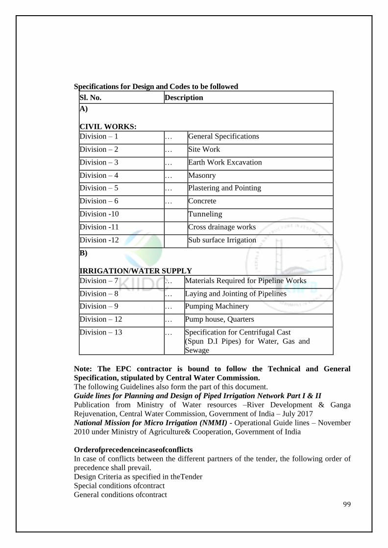
99
Specifications for Design and Codes to be followed
Sl. No. Description
A)
CIVIL WORKS:
Division – 1 … General Specifications
Division – 2 … Site Work
Division – 3 … Earth Work Excavation
Division – 4 … Masonry
Division – 5 … Plastering and Pointing
Division – 6 … Concrete
Division -10 Tunneling
Division -11 Cross drainage works
Division -12 Sub surface Irrigation
B)
IRRIGATION/WATER SUPPLY
Division – 7 … Materials Required for Pipeline Works
Division – 8 … Laying and Jointing of Pipelines
Division – 9 … Pumping Machinery
Division – 12 … Pump house, Quarters
Division – 13 … Specification for Centrifugal Cast
(Spun D.I Pipes) for Water, Gas and
Sewage
Note: The EPC contractor is bound to follow the Technical and General
Specification, stipulated by Central Water Commission.
The following Guidelines also form the part of this document.
Guide lines for Planning and Design of Piped Irrigation Network Part I & II
Publication from Ministry of Water resources –River Development & Ganga
Rejuvenation, Central Water Commission, Government of India – July 2017
National Mission for Micro Irrigation (NMMI) - Operational Guide lines – November
2010 under Ministry of Agriculture& Cooperation, Government of India
Orderofprecedenceincaseofconflicts
In case of conflicts between the different partners of the tender, the following order of
precedence shall prevail.
Design Criteria as specified in theTender
Special conditions ofcontract
General conditions ofcontract
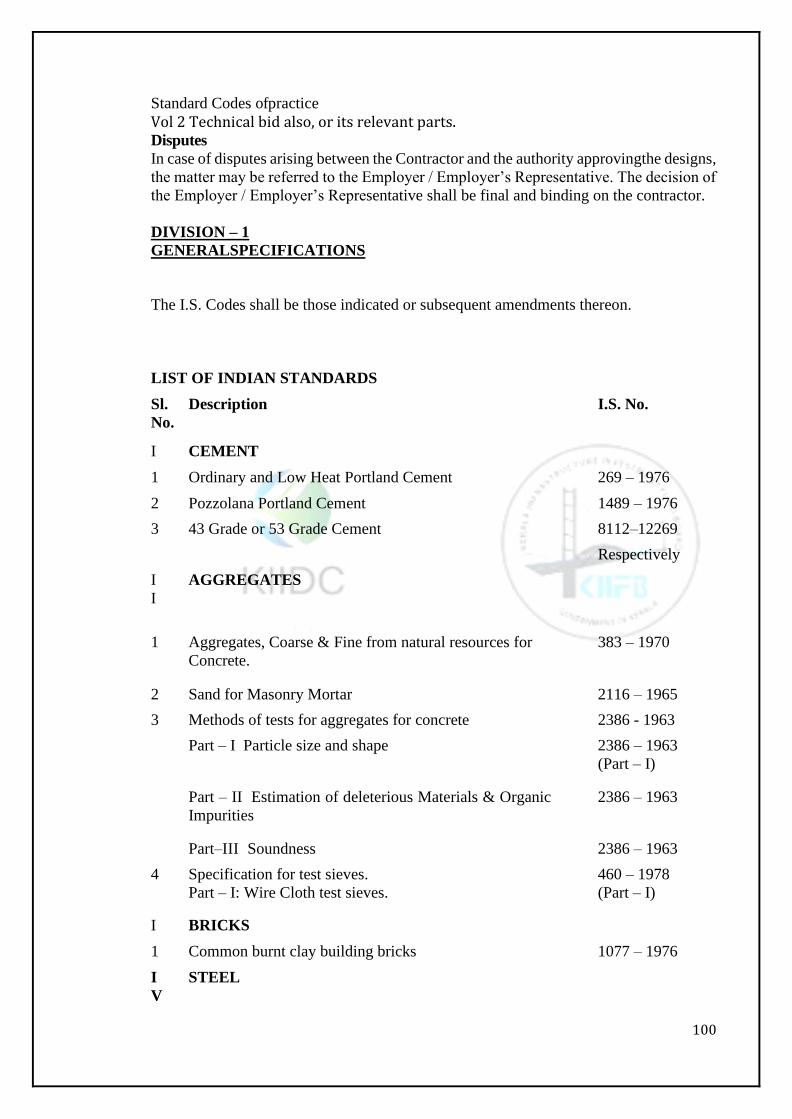
100
Standard Codes ofpractice
Vol 2 Technical bid also, or its relevant parts. Disputes
In case of disputes arising between the Contractor and the authority approvingthe designs,
the matter may be referred to the Employer / Employer’s Representative. The decision of
the Employer / Employer’s Representative shall be final and binding on the contractor.
DIVISION – 1
GENERALSPECIFICATIONS
The I.S. Codes shall be those indicated or subsequent amendments thereon.
LIST OF INDIAN STANDARDS
Sl.
No.
Description I.S. No.
I CEMENT
1 Ordinary and Low Heat Portland Cement 269 – 1976
2 Pozzolana Portland Cement 1489 – 1976
3 43 Grade or 53 Grade Cement 8112–12269
Respectively
I
I
AGGREGATES
1 Aggregates, Coarse & Fine from natural resources for
Concrete.
383 – 1970
2 Sand for Masonry Mortar 2116 – 1965
3 Methods of tests for aggregates for concrete 2386 - 1963
Part – I Particle size and shape 2386 – 1963
(Part – I)
Part – II Estimation of deleterious Materials & Organic
Impurities
2386 – 1963
Part–III Soundness 2386 – 1963
4 Specification for test sieves.
Part – I: Wire Cloth test sieves.
460 – 1978
(Part – I)
I BRICKS
1 Common burnt clay building bricks 1077 – 1976
I
V
STEEL
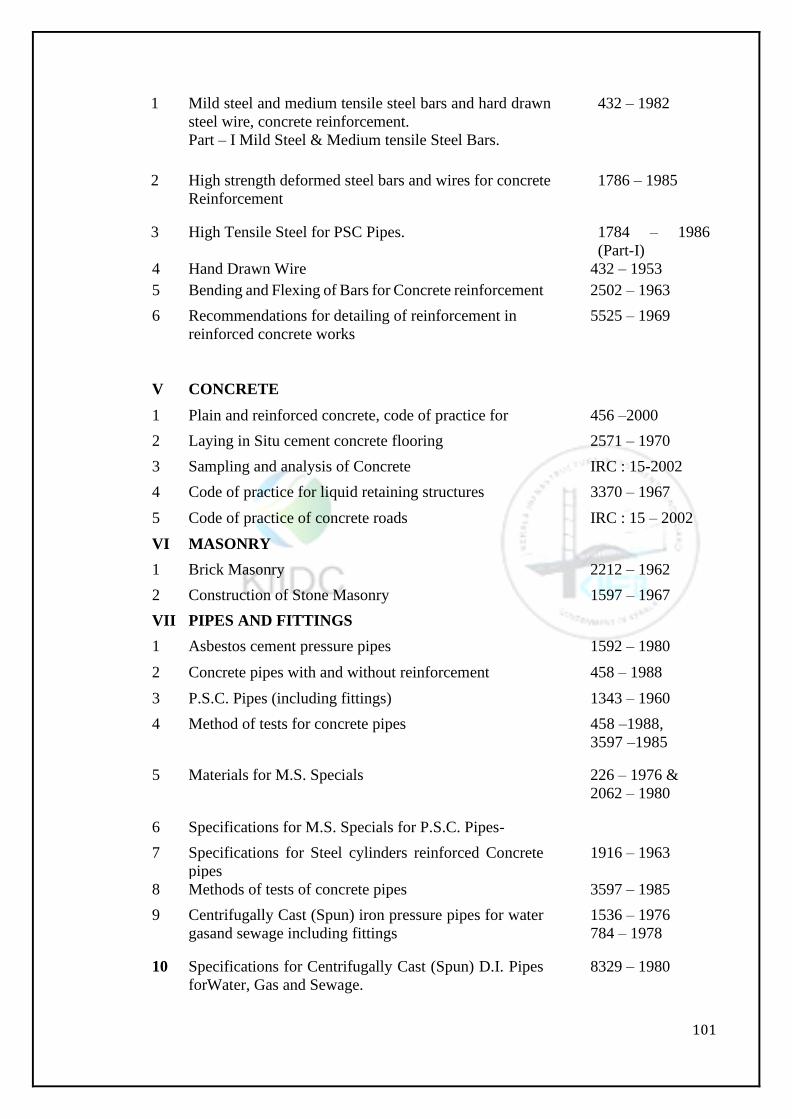
101
1 Mild steel and medium tensile steel bars and hard drawn
steel wire, concrete reinforcement.
Part – I Mild Steel & Medium tensile Steel Bars.
432 – 1982
2 High strength deformed steel bars and wires for concrete
Reinforcement
1786 – 1985
3 High Tensile Steel for PSC Pipes. 1784 – 1986
(Part-I)
4 Hand Drawn Wire 432 – 1953
5 Bending and Flexing of Bars for Concrete reinforcement 2502 – 1963
6 Recommendations for detailing of reinforcement in
reinforced concrete works
5525 – 1969
V CONCRETE
1 Plain and reinforced concrete, code of practice for 456 –2000
2 Laying in Situ cement concrete flooring 2571 – 1970
3 Sampling and analysis of Concrete IRC : 15-2002
4 Code of practice for liquid retaining structures 3370 – 1967
5 Code of practice of concrete roads IRC : 15 – 2002
VI MASONRY
1 Brick Masonry 2212 – 1962
2 Construction of Stone Masonry 1597 – 1967
VII PIPES AND FITTINGS
1 Asbestos cement pressure pipes 1592 – 1980
2 Concrete pipes with and without reinforcement 458 – 1988
3 P.S.C. Pipes (including fittings) 1343 – 1960
4 Method of tests for concrete pipes 458 –1988,
3597 –1985
5 Materials for M.S. Specials 226 – 1976 &
2062 – 1980
6 Specifications for M.S. Specials for P.S.C. Pipes-
7 Specifications for Steel cylinders reinforced Concrete
pipes
1916 – 1963
8 Methods of tests of concrete pipes 3597 – 1985
9 Centrifugally Cast (Spun) iron pressure pipes for water
gasand sewage including fittings
1536 – 1976
784 – 1978
10 Specifications for Centrifugally Cast (Spun) D.I. Pipes
forWater, Gas and Sewage.
8329 – 1980
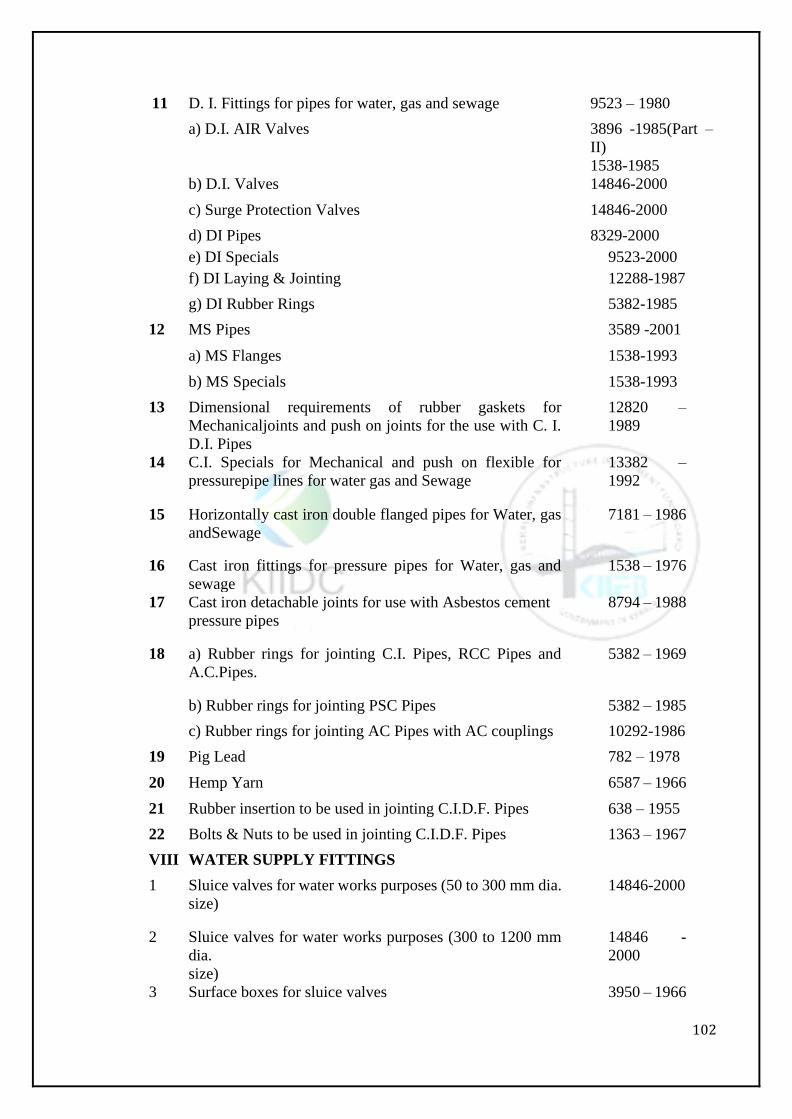
102
11 D. I. Fittings for pipes for water, gas and sewage 9523 – 1980
a) D.I. AIR Valves 3896 -1985(Part –
II)
1538-1985
b) D.I. Valves 14846-2000
c) Surge Protection Valves 14846-2000
d) DI Pipes 8329-2000
e) DI Specials 9523-2000
f) DI Laying & Jointing 12288-1987
g) DI Rubber Rings 5382-1985
12 MS Pipes 3589 -2001
a) MS Flanges 1538-1993
b) MS Specials 1538-1993
13 Dimensional requirements of rubber gaskets for
Mechanicaljoints and push on joints for the use with C. I.
D.I. Pipes
12820 –
1989
14 C.I. Specials for Mechanical and push on flexible for
pressurepipe lines for water gas and Sewage
13382 –
1992
15 Horizontally cast iron double flanged pipes for Water, gas
andSewage
7181 – 1986
16 Cast iron fittings for pressure pipes for Water, gas and
sewage
1538 – 1976
17 Cast iron detachable joints for use with Asbestos cement
pressure pipes
8794 – 1988
18 a) Rubber rings for jointing C.I. Pipes, RCC Pipes and
A.C.Pipes.
5382 – 1969
b) Rubber rings for jointing PSC Pipes 5382 – 1985
c) Rubber rings for jointing AC Pipes with AC couplings 10292-1986
19 Pig Lead 782 – 1978
20 Hemp Yarn 6587 – 1966
21 Rubber insertion to be used in jointing C.I.D.F. Pipes 638 – 1955
22 Bolts & Nuts to be used in jointing C.I.D.F. Pipes 1363 – 1967
VIII WATER SUPPLY FITTINGS
1 Sluice valves for water works purposes (50 to 300 mm dia.
size)
14846-2000
2 Sluice valves for water works purposes (300 to 1200 mm
dia.
size)
14846 -
2000
3 Surface boxes for sluice valves 3950 – 1966
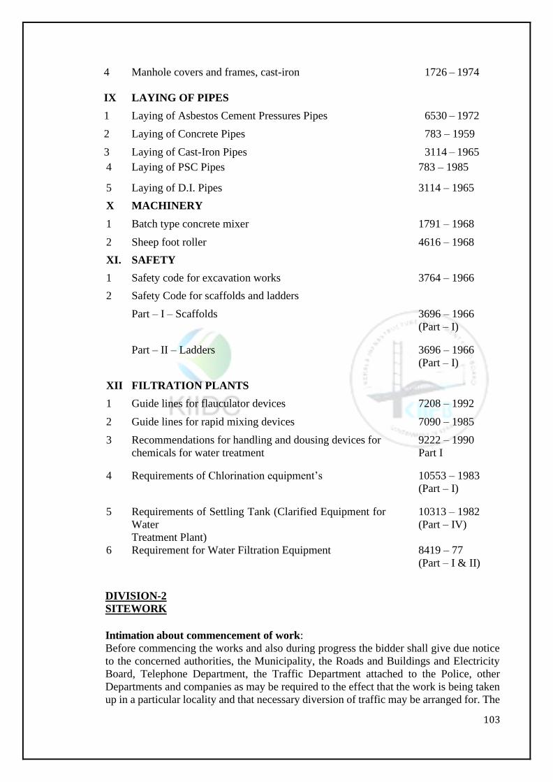
103
4 Manhole covers and frames, cast-iron 1726 – 1974
IX LAYING OF PIPES
1 Laying of Asbestos Cement Pressures Pipes 6530 – 1972
2 Laying of Concrete Pipes 783 – 1959
3 Laying of Cast-Iron Pipes 3114 – 1965
4 Laying of PSC Pipes 783 – 1985
5 Laying of D.I. Pipes 3114 – 1965
X MACHINERY
1 Batch type concrete mixer 1791 – 1968
2 Sheep foot roller 4616 – 1968
XI. SAFETY
1 Safety code for excavation works 3764 – 1966
2 Safety Code for scaffolds and ladders
Part – I – Scaffolds 3696 – 1966
(Part – I)
Part – II – Ladders 3696 – 1966
(Part – I)
XII FILTRATION PLANTS
1 Guide lines for flauculator devices 7208 – 1992
2 Guide lines for rapid mixing devices 7090 – 1985
3 Recommendations for handling and dousing devices for
chemicals for water treatment
9222 – 1990
Part I
4 Requirements of Chlorination equipment’s 10553 – 1983
(Part – I)
5 Requirements of Settling Tank (Clarified Equipment for
Water
Treatment Plant)
10313 – 1982
(Part – IV)
6 Requirement for Water Filtration Equipment 8419 – 77
(Part – I & II)
DIVISION-2
SITEWORK
Intimation about commencement of work:
Before commencing the works and also during progress the bidder shall give due notice
to the concerned authorities, the Municipality, the Roads and Buildings and Electricity
Board, Telephone Department, the Traffic Department attached to the Police, other
Departments and companies as may be required to the effect that the work is being taken
up in a particular locality and that necessary diversion of traffic may be arranged for. The
104
bidder shall cooperate with the Departments concerned and provide for necessary
barricading of roads, protections to existing underground mains, cables etc.
2.2 Cross Drainage:
The bidder shall handle all flows from natural drainage channels intercepted by the work
under these specifications, perform any additional excavation and grading for drainage as
directed and maintain any temporary construction required to bypass or otherwise cause
the flows to be harmless to the work and property. When the temporary construction is
no longer needed and prior to acceptance of the work, the bidder shall remove the
temporary construction and restore the site to its original condition as approved by the
Engineer-in-Charge. The cost of all work and materials required by this paragraph shall
be included by the bidder in the unit prices quoted in the section 6 of Vol. III (bill of
quantities) and no separate payment will be made for the same.
2.3 Stacking of Excavated Material:
Where the location of the work is such and does not permit the deposition of excavated
earth while digging trenches for laying pipes, the excavated earth should be conveyed to
a convenient place and deposited there temporarily, as directed by the Engineer-in-
Charge. Such deposited earth shall be reconveyed to the site of work for the purpose of
refilling of trenches, if such deposited soil is suitable for refilling. The unit rate for trench
work of excavation and refilling shall include the cost of such operations.
2.4 Disposal of Surplus Earth:
The rate for excavation of trench work, shall include charges of shoring, strutting, any of
these contingent works. While bailing out water care should be taken to see that the bailed
out water is properly channelized to flow away without stagnation or inundating the
adjoining road surfaces and properties.
2.5. Shoring, Strutting and Bailing out Water:
The rate for excavation of trench work shall include charges of shoring, strutting, bailing
out water wherever necessary and no extra payment will be made for any of these
contingent works. While bailing out water care should be taken to see that the bailed out
water is properly channelized to flow away without stagnation or inundating the adjoining
road surfaces and properties.
DIVISION-3
EARTH WORK
EARTH WORK -GENERAL:
3.1.1. Earth work diagrams and Data:
To the extent that they exist plans and earth work data prepared for the Government’s
(that is Government of Kerala) studies of earth work for construction of the related works
will be available for Inspection by the bidders in the Office of the concerned Engineer-
in-Charge.
Such information is made available solely for the convenience of bidders. The
Government does not represent that this information is accurate or complete. Bidders are
cautioned that this information is subject to revision and that the Government disclaims
responsibility for any interpretations, deductions or conclusions which may be made there
from. It is not intended that this earth work information will limit or prescribe the
excavation and handling procedure of the contractor, and the Government reserves the
right to utilize and distribute earth work materials during the progress of work as best
serves the interest of the Government.
105
3.1.2 Compacting Earth Materials:
Where compacting of earth materials is required, the materials shall be deposited in
horizontal layers and compacted as specified in this paragraph. The excavation, placing,
moistening and compacting operations shall be such that the materials will be uniformly
compacted throughout the required section and will be homogeneous, free from lenses,
pockets, streaks, voids, lamination or other imperfections. The compaction shall be
carried out in accordance with the relevant clauses of I.S 4701 – 1982.
3.2EXCAVATION:
Classification of Excavation:
Except, as other-wise provided in these specifications, material excavated will be
measured in excavation to the lines shown on the drawings or as provided in these
specifications, and all materials so required to be excavated will be paid for at the
applicable prices bid in the schedule for excavation. No additional allowance above the
price bid in the schedule will be made on account of any of the material being wet. Bidders
and the contractors must assume all responsibility for deducting and concluding as to the
nature of the materials to be excavated and the difficulties of making and maintaining the
required excavation. The Government does not represent that the excavation can be
performed or maintained at the pay lines described in these specifications or shown on
the drawings.
Excavation for removal of debris and deposited earth on berms while forming roads is to
be carried out as specified in relevant clauses of IS: 4701-1982 as compared before lying
of berms with the same setting of roads.
Excavation for Structures:
General:
Excavation for the foundation of structures shall be to the elevation shown on the
drawings or as directed by the Engineer-in-Charge. In so far as practicable, the material
removed in excavation for structures shall be used for back fill and embankments.
Otherwise it shall be disposed off as specified in paragraph 2.4.
Foundations for Structures:
The Contractor shall prepare the foundations at structure/sites by methods which will
provide firm foundation for the structures. The bottom and side slopes of common
excavation upon or against which the structure is to be placed shall be finished to the
prescribed dimensions and the surfaces so prepared shall be moistened and tamped with
suitable tools to form firm foundation upon or against which to place the structure. The
Contractor shall prepare the foundation for the structures as shown on respective
drawings. The natural foundation material beneath, the required excavation shall be
moistened if required and compacted in place.
Separate payment will not be made to the contractor for Moistening and compacting the
foundation of structures. The contractor shall include cost thereof in the price bid per
cubic meter of the item of the Bill of quantities for preparation of foundations.
Whenever unsuitable material is encountered in the foundation for a structure the
Engineer-in-Charge will direct additional excavation to remove the unsuitable material.
The cost of such additional excavation shall be paid at the unit price bid in the Bill of
quantities for earth. The additional excavation shall be refilled by selected bedding
material and compacted.
Over Excavation:
If at any point in common excavation the foundation material is excavated beyond the
lines required to receive the structure, or if at any point in common excavation the natural
foundation material is disturbed or loosened during the excavation process, it shall be
106
compacted in place or where directed, it shall be removed and replaced as follows. In
excavation soils, the over excavation shall be filled in by selected bedding material and
compacted. In excavation in rock it shall be filled with M5 grade cement concrete. Any
and all excess excavation or over excavation performed by the Contractor for any purpose
or reason except for additional excavation as may be prescribed by the Engineer-in-
Charge and whether or not due to the fault of the contractor shall be at the expense of the
contractor. Filling for such excess excavation or over excavation shall be at the expense
of the contractor.
Measurement for payment:
Excavation for structures will be measured for payment, for box cutting with vertical
sides of foundation dimensions. The contractor will have to make his own arrangement
for shoring, strutting, provision of adequate slopes for the sides to prevent slips etc., and
no separate charge will be paid for any incidental charges arising either during excavation
of foundation or construction of the structure.
Payment:
Payment for excavation for structures will be made at the unit price per cubic meter bid
there for in the Bill of quantities for excavation for structures. The unit price bid in the
bill of quantities for excavation for structures shall include the cost of all labour and
materials for coffer dam and other temporary construction, of all pumping and
dewatering, of all other work necessary to maintain the excavation in good order during
construction, of removing such temporary construction where required and shall include
the cost of disposal of the excavated material.
3.3 BACKFILL:
Back fill around structures
General:
The item of the schedule for backfill around structures including pipe portions of
structures includes all backfill required to be placed under these specifications.
Materials:
The type of material used for backfill, the amount thereof, and the manner of depositing
the material shall be subject to approval of Engineer-in-Charge. In so far as practicable
backfill material shall be obtained from material removed in required excavations for
structures. But when sufficient suitable material is not available from this source,
additional material shall be obtained from approved borrow-areas. The borrow pit
excavation shall be in accordance with clause-9.1 to 9.3 of IS: 4701-1982.
Backfill material shall contain no stones larger than 80 millimeters in diameter. If the
excavation for the foundation of the structure is in swelling soils, a layer of cohesive non-
swelling soil conforming to I.S.9451-1980 should be interposed between the swelling soil
of the structure and compacted to at least 95% standard proctor’s density.
Placing Backfill:
Backfill shall be placed to the lines and grades shown on the drawings as prescribed in
this paragraph or as directed by the Engineer-in-Charge. All backfill shall be placed
carefully and spread in uniform layers not exceeding 150 mm, so that all spaces about
rocks and clods will be filled. Each layer shall be watered and well compacted before the
succeeding layer is laid, care being taken not to disturb the constructed structure. Backfill
shall be brought up as uniformly as practicable on both sides of walls and all sides of
structure to prevent unequal loading. Backfill shall be placed to about the same elevation
on both sides of the pipe positions of the structures to prevent unequal loading and
displacement of the pipe.
Measurement and Payment:
Excavation refill required to be placed about structures that is within the pay line limits
107
for excavation for the structures, will be measured in place for payment as backfill about
structure provided that where the contractor elects not to excavate material which is
outside the limits of the actual structure or pipe, but within the pay line limits of
excavation, all such material will be included in the measurement for payment of backfill.
The unit price bid therefore in the Bill of quantities for excavation of foundation of
structure shall include cost of backfilling above the structure up to ground level. No
separate payment will be made for backfill of foundation.
Refill of excavation performed outside the established pay lines for excavation for
structures shall be placed in the same manner as specified for the adjacent backfill and
such refill shall be placed at the expense of the contractor.
DIVISION-4
MASONRY
MATERIALS:
Stone for Masonry:
General:
The stones used for stone masonry shall conform to the relevant specifications of Clause
10 of IS: 1597 (Part-I) 1967 code of practice for construction of stone Masonry Part-I
Rubble Stonemasonry.
The stone of the required quality shall be obtained from the quarries specified in the lead
chart appended to the Schedule. The common types of natural stones which are generally
used are Granite and other ingenious rocks, and shall be free from defects like decay,
cavities, cracks, flaws, sand, holes, soft seams, veins, and patches of soft or loose
materials or any other deleterious materials like iron oxide Organic Impurities etc. They
shall be free from rounded, worn or weathered surfaces or skin or coating which prevents
the adherence of mortar. All stones used shall be clean of uniform color and texture,
strong, hard and durable.
The percent of water absorption shall not exceed 5% by weight as determined in
accordance with IS: 1124-1974.
The approval of the quarries by the Engineer-in-Charge shall not be constructed as
constituting approval of all or any of the stones collected from the deposits; and the bidder
will be held responsible for suitability of the stones used in the work.
Cost:
The cost of collecting the stones for masonry will not be paid for separately and their cost
including the cost of quarrying, transporting, stacking, royalty Seignorage charges shall
be included in the unit price per cubic meter bid there for in the relevant item in the bill
of quantities.
4.1.2 Brick for Masonry
(a) General:
Bricks used for brick masonry shall conform to the relevant specifications of I.S. 1077-
1986 common burnt clay building bricks.
Bricks shall be hand or machine moulded. They shall be sound, hard, and homogeneous
in texture well burnt and shall give a clear ringing sound when struck. They shall be
clean, free from warping, distortion, cracks, chips, flaws, stones and nodules of free lime.
Unless otherwise specified the sizes of the bricks shall be 190 x 90 x 90 mm. The
compressive strength shall not be less than 40 Kg/Cm2. The percentage of water
absorption shall not be more than 20 per cent by weight after 24 hours immersion in cold
108
water.
(b) Cost:
The cost of collecting the bricks for masonry will not be paid for separately and their cost
including the cost of transporting, stacking, royalty Seignoragecharges shall be included
in the unit price per cubic meter bid therefore in the relevant item in the bill of quantities.
4.1.3 Sand forMasonry:
(a) General:
Sand shall generally conform to specifications given in paragraph 6.2.5 except that the
sand for mortar shall conform to the grading of sand given in clause 4 of I.S.2116 -1189
as detailed below in Table 4(b).
(b)Grading of Sand for use in Masonry Mortars:
Table 4 :
I.S Sieve Designation
Percentage passing by Mass
4.75 mm 100
2.36 mm 90 to 100
1.18 mm 70 to 100
600 Micron 40 to 100
300 Micron 5 to 70
150 Micron 0 to 15
A sand whose grading falls out-side the specified limits due to excess or deficiency of
coarse or fine particles may be processed to comply with the standard by screening
through a suitably sized sieve and/or blending with required quantities of suitable size
and particles.
The procurement of sand for masonry shall confirm to the specifications given in
paragraph 6.2.5.
Cost:
The cost of sand for masonry will not be measured and paid separately and the cost of
sand including the cost of stripping, transporting and storing and royalty charges shall be
included in the unit price per cubic meter bid there for in the relevant item of work in the
bill of quantities for which this and is required.
4.1.4 Cement:
General:
As per clause 4 of I.S. 456-1978 for the purposes of these specifications, cement used
shall be any of the following with the prior approval of the Engineer-in-Charge Ordinary
Portland (OPC) – GRADES 43 & 53 Conforming to BIS : 811 : 12269 respectively (or)
Portland Pozzolanacement conforming to I.S. 1489 relevant amendments up to date. The
provisions of this paragraph apply to cement for use in cast-in-place concrete required
under these specifications. Portland cement required for items such as concrete pipes,
precast concrete structural members and other precast concrete products, for grout and
mortar and for other item is provided for in the applicable paragraphs of these
specifications covering the items for which such Portland cement is required.
4.1.5Water
The water used in making and curing of concrete, mortar and grout shall be free from
109
objectionable quantities of silt, organic matter, injurious amounts of oils, acids, salts, and
other impuritiesetc., as per I.S. specification No.456-1978. The Engineer-in-Charge will
determine whether or not such quantities of impurities are objectionable.
Such determination will usually be made by comparison of compressive strength, water
requirement, time of set and other properties of concrete made with distilled or very clean
water and concrete made with the water proposed for use. Permissible limits for solids
when tested in accordance with IS: 3025-1964 shall be as tabulated below.
Permissible limit for Solids:
Maximum permissible limit
If any water to be used in concrete, mortar or grout is suspected by the Engineer-in-
Charge of exceeding the permissible limits of solids, samples of water will be obtained
and tested by the Engineer-in-Charge in accordance with I.S. 3025-1964.
4.2MORTAR
4.2.1Preparation of Mortar:
Unless otherwise specified, the cement mortar used in Masonry works shall be cement
mortar mix MM5 (1:5) grade using minimum 288 Kgs. of cement per cubic meter of
mortar.
Mixing shall be done thoroughly preferably in a mechanical mixer. In such cases, the
cement and sand in the specified proportions shall be mixed dry thoroughly in the mixer
operated manually or by power.
Water shall be added gradually and wet mixing continued at least for 3 minutes. Water
should not be more than that required for bringing the mortar to the required working
consistency of 90 to 130 millimeters as required in clause 9.11 of I.S. 2250-1981. The
mix shall be clean and free from injurious kind of soil, acid, alkali, organic matter or
deleterious substances.
4.2.2 Time of use of Cement Mortar:
Cement mortar shall be used as soon as possible after mixing and before it has begun to
set, within 30 minutes after the water is added to the dry mixture.
Mortar unused for more than 30 minutes should not be used and shall be removed from
the site of work. The cost of such wasted mortar shall be borne by the bidder. The use of
retempered mortar will not be permitted to be used for the masonry.
4.2.3 Tests of Mortar:
Mortar Test cubes shall be cast for the mortar used on the work and shall be tested in
1.
Organic
200 Mg/liter
2.
Inorganic
3000 mg/liter
3.
Sulphates(asSO4)
500 mg/liter
4.
Chlorides (asCL)
2000 mg/liter for plain concrete
work and
1000 mg/liter for R.C.C. work
5.
Suspended matter
2000 mg/liter
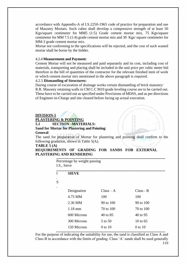
110
accordance with Appendix-A of I.S.2250-1965 code of practice for preparation and use
of Masonry Mortars. Such cubes shall develop a compressive strength of at least 50
Kgs/square centimeter for MM5 (1:5) Grade cement mortar mix, 75 Kgs/square
centimeter for MM 7.5 (1:4) grade cement mortar mix and 30 Kgs/ square centimeter for
MM-3 grade cement mortar mix.
Mortar not conforming to the specifications will be rejected, and the cost of such wasted
mortar shall be borne by the bidder.
4.2.4 Measurement and Payment:
Cement Mortar will not be measured and paid separately and its cost, including cost of
materials, transporting and placing shall be included in the unit price per cubic meter bid
therefore in the bill of quantities of the contractor for the relevant finished item of work
or which cement mortar mix mentioned in the above paragraph is required.
4.2.5 Dismantling of Structures:
During course of excavation of drainage works certain dismantling of brick masonry/
R.R. Masonry retaining walls in CM C.C M10 grade leveling course are to be carried out.
These have to be carried out as specified under Provisions of MDSS, and as per directions
of Engineer-in-Charge and site cleared before facing up actual execution.
DIVISION-5
PLASTERING & POINTING
5.1 SECTION –MATERIALS:
Sand for Mortar for Plastering and Pointing:
General:
The sand for preparation of Mortar for plastering and pointing shall confirm to the
following gradation, shown in Table 5(A).
TABLE 5 (A)
REQUIREMENTS OF GRADING FOR SANDS FOR EXTERNAL
PLASTERING AND RENDERING
Percentage by weight passing
I.S., Sieve
I
.
S
.
SIEVE
Designation Class – A Class - B
4.75 MM 100 100
2.36 MM 90 to 100 90 to 100
1.18 mm 70 to 100 70 to 100
600 Microns 40 to 85 40 to 95
300 Microns 5 to 50 10 to 65
150 Microns 0 to 10 0 to 10
For the purpose of indicating the suitability for use, the sand is classified as Class A and
Class B in accordance with the limits of grading. Class ‘A’ sands shall be used generally

111
for plastering and pointing, and when they are not available, Class ‘B’ sands may be used
with the approval of Engineer-in-Charge.
The procurement of sand for Mortar for plastering and pointing shall conform to the
specifications given in paragraph 6.2.5.
Cost:
The cost of sand for mortar for plastering and pointing will not be measured and paid
separately, and the cost of sand including the cost of stripping, transporting and storing
and royalty charges shall be included in the unit price per Cubic meter bid there for in the
relevant item of work in the Schedule ‘A’ for which this sand is required.
5.1.3Cement:
The specifications and conditions specified for supply for cement in paragraph 4.1.4 shall
be applicable here also.
Portland pozzolana cement conforming to I.S. 1489-1976 shall be used for preparation
of mortar for plastering and pointing work. Ordinary Portland cement – Grades 43 & 53
may also be used in the event of non-availability of P.P.C.
5.1.4Water:
The specifications and conditions specified for procurement of water in paragraph 4.1.5
shall be applicable here also.
5.2 SECTION –MORTAR:
Preparation of Mortar for Plastering work:
Unless otherwise specified, the cement mortar used in plastering work shall be in cement
mortar mix of MM. 7.5 (1:4) grade, using minimum 360 Kgs. of cement per cubic meter
of mortar.
The other specifications and conditions enunciated in paragraph 4.2.1 shall apply for this
mortar for plastering work also.
5.2.2 Preparation of Mortar for Pointing:
The cement mortar used in pointing work shall be cement mortar mix of M.M 7.5 grade,
using 480 Kgs. of cement per cubic meter of mortar.
The other specifications and conditions enunciated in paragraph 4.2.1 shall apply for this
mortar for pointing work also.
5.3 SECTION – PLASTERING WITH CEMENT MORTAR MIX. MM 7.5
GRADE 20 MM THICK:
5.3.1Preparation ofSurface:
The roughening of the background improves the bond of plaster. All joints shall be
thoroughly raked. After roughening the surface, care shall be taken to moisten the surface
sufficiently before plastering as otherwise rashly exposed surface may tend to absorb
considerable amount of water from the plaster. The surface shall be wetted evenly before
applying the plaster. Care shall be taken to see that the surface is not too dry as this may
cause lack of adhesion or excessive suction of water from the plaster. A fog spray may
be used for this work. As far as possible, the plaster work shall be doneunder shade.
5.3.2Laying of Plastering with Cement Mortar Mix MM.7.5 grade 20 mm thick:
The mortar used for plastering shall be stiff enough to cling and hold when laid. To ensure
even thickness and true surface, plaster shall be applied in patches of 150 mm x150 mm
of neither the required 20 mm thickness at nor more than 2 meters intervals horizontally
and vertically over the entire surface to serve as guides. The surface of these guides shall
be truly in the plane of the furnished plaster surface and truly plumb. The mortar shall
then be applied to the surface to be plastered between the guides with a trowel. Each
trowel full of mortar shall overlap and sufficient pressure shall be used to force it into
thorough contact with the surface. On relatively smooth surfaces, the mortar shall be
dashed on with the trowel to ensure adequate bond. The mortar shall be applied to a
112
thickness slightly more than that specified, using a string, stretched out between the
guides. This shall then be brought to a true surface by working with a long wooden float
with small sawing motion. The surface shall be periodically checked with a string
stretched across it. Finally the surface shall be rendered smooth with a small wooden
float, over working shall be avoided. All corners, arises, and junctions shall be brought
truly to a line with any necessary rounding or chamfering.
If it is necessary to suspend the work at the end of the day, it shall be left in a clean
horizontal or vertical line not nearer than 150 millimeters for any corner or arises or on
parapet tops or on copings etc. When recommending the work, the edges of the old work
shall be scraped clean and treated with cement slurry before the new plaster is laid
adjacent to it. After the first coat is done, it shall be kept undisturbed for the next 24 hours
and thereafter kept moist and not permitted to dry until the final rendering is applied.
After the plaster has sufficiently hardened cement slurry with cream like consistency shall
be applied as thinly and evenly and rubbed to a fine condition.
The finished surface shall be cured with water for a period of 10 days.
5.4 SECTION – POINTING TO STONE MASONRY WITH CEMENT MORTAR
MIX MM.75 GRADE
The joints in the masonry shall be raked out to a depth not less than the width of the joint
or as directed when the mortar is green. Joints are to be brushed clean of dust and loose
particles with a stiff brush. The area shall then be washed and the joints thoroughly wetted
before pointing is commenced.
5.4.2 Flush Pointing with Cement Mortar Mix MM. 7.5 Grade for Rubble Masonry:
The pointing to be done shall be flush pointing with cement mortar mix MM. 7.5 grade.
The mortar shall be pressed into the raked-out joints according to the types of pointing
required. The mortar shall not be spread over the corners, edges or surface of the masonry.
The pointing shall then be finished as detailed below. The mortar shall be finished off
flush and level with the edges of the stones, so as to give a smooth appearance. The edges
shall be neatly trimmed with a trowel and a straight edge.
The pointing shall be cured for seven days.
5.5 SECTION – MEASUREMENT AND PAYMENT:
Plastering:
The measurement of plastering will be in units of square meters, and it shall be paid at
the relevant unit price bid per ten square meters of Plastering in the schedule Bill of
Quantities which unit price shall include the cost of materials, their conveyance, charges
for preparation of mortar including mixing charges and charges for performing the
plastering work as illustrated in this division, including curing.
Pointing:
The measurement for pointing will be in units of square meters, and it shall be paid at the
relevant unit prices per ten square meters bid in the schedule Bill of quantities which unit
price shall include the cost of materials, their conveyance, charges for preparation of
mortar including mixing charges and charges for performing the pointing work as
illustrated in this division, including curing.
113
DIVISION-6
CONCRETE
6.1CONCRETESTRUCTURES:
6.1.1 Concrete Structures:
(a) Concrete in structures shall conform to the requirements of Paragraph6.2
(b) Measurement and payment for concrete in structures will be made as prescribed in
paragraphs 6.3 &6.4.
6.1.2 Construction of Structures:
Cast-in-place concrete for the structures shall conform to the requirements of section. The
structures shall be built to the lines, grades and dimensions shown on the drawings. The
dimensions of each structure as shown on the drawings will be subject to such
modifications as may be found necessary by the Engineer-in-Charge to adopt the structure
to the conditions disclosed by the excavation or to meet other conditions. Where the
thickness of any portion of a concrete structure is variable, it shall vary uniformly between
the dimensions shown.
Where necessary, as determined by the Engineer-in-Charge, the Contractor will be
furnished additional detailed drawings of the structures to be constructed. The bidder will
not be entitled to any additional allowances above the prices bid in the schedule by reason
of the dimensions fixed by the Engineer-in-Charge or by reasons of any modifications or
extensions of a minor character to adopt a structure to a structure at site, as determined
by the Engineer-in-Charge.
The cost of furnishing all materials and performing all work for installing timber, metal
and other accessories for which specific prices are not provided in the schedule, shall be
included in the applicable prices bid in the schedule for the work to which such items are
appurtenant.
6.2 GENERAL CONCRETEREQUIREMENTS:
6.2.1Composition:
(a) General:
Concrete shall be composed of cement, sand, coarse aggregate, water and admixtures (if
any) as specified, all well mixed and brought to the proper consistency.
(b)Nominal maximum size of Aggregates:
In coarse aggregates to be used in concrete shall be as large as practicable, consistent with
required strength, spacing of reinforcement and embedded items, and placement
thickness. The size of the coarse aggregate to be used will be determined by the Engineer-
in-Charge and may vary incrementally according to the conditions encountered in each
concrete placement. Nominal maximum size of aggregate for concrete in structures shall
be as indicated in the relevant drawings appended to the contract documents. Smaller
coarse aggregate than specified shall be used where in the opinion of the Engineer-in-
Charge that proper placement of concrete is impracticable with the size of the aggregate
specified in the drawings.
Mix Proportions:
The proportions of various ingredients to be used in the concrete for different parts of the
work will be established by proper mix design by the Engineer-in-Charge during the
progress of the work. In proportioning concrete, the quantity of both cement and
aggregate should be determined by mass as per clause 9.2 of I.S. 456 -1978, water shall
be either measured by volume in calibrated tanks or weighted. All measuring equipment
shall be maintained in a clean serviceable condition and their accuracy periodically
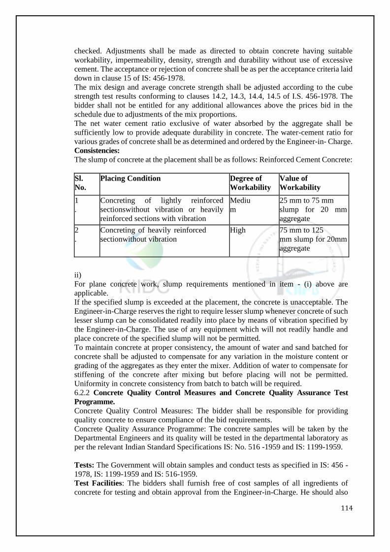
114
checked. Adjustments shall be made as directed to obtain concrete having suitable
workability, impermeability, density, strength and durability without use of excessive
cement. The acceptance or rejection of concrete shall be as per the acceptance criteria laid
down in clause 15 of IS: 456-1978.
The mix design and average concrete strength shall be adjusted according to the cube
strength test results conforming to clauses 14.2, 14.3, 14.4, 14.5 of I.S. 456-1978. The
bidder shall not be entitled for any additional allowances above the prices bid in the
schedule due to adjustments of the mix proportions.
The net water cement ratio exclusive of water absorbed by the aggregate shall be
sufficiently low to provide adequate durability in concrete. The water-cement ratio for
various grades of concrete shall be as determined and ordered by the Engineer-in- Charge.
Consistencies:
The slump of concrete at the placement shall be as follows: Reinforced Cement Concrete:
Sl.
No.
Placing Condition Degree of
Workability
Value of
Workability
1
.
Concreting of lightly reinforced
sectionswithout vibration or heavily
reinforced sections with vibration
Mediu
m
25 mm to 75 mm
slump for 20 mm
aggregate
2
.
Concreting of heavily reinforced
sectionwithout vibration
High 75 mm to 125
mm slump for 20mm
aggregate
ii)
For plane concrete work, slump requirements mentioned in item - (i) above are
applicable.
If the specified slump is exceeded at the placement, the concrete is unacceptable. The
Engineer-in-Charge reserves the right to require lesser slump whenever concrete of such
lesser slump can be consolidated readily into place by means of vibration specified by
the Engineer-in-Charge. The use of any equipment which will not readily handle and
place concrete of the specified slump will not be permitted.
To maintain concrete at proper consistency, the amount of water and sand batched for
concrete shall be adjusted to compensate for any variation in the moisture content or
grading of the aggregates as they enter the mixer. Addition of water to compensate for
stiffening of the concrete after mixing but before placing will not be permitted.
Uniformity in concrete consistency from batch to batch will be required.
6.2.2 Concrete Quality Control Measures and Concrete Quality Assurance Test
Programme.
Concrete Quality Control Measures: The bidder shall be responsible for providing
quality concrete to ensure compliance of the bid requirements.
Concrete Quality Assurance Programme: The concrete samples will be taken by the
Departmental Engineers and its quality will be tested in the departmental laboratory as
per the relevant Indian Standard Specifications IS: No. 516 -1959 and IS: 1199-1959.
Tests: The Government will obtain samples and conduct tests as specified in IS: 456 -
1978, IS: 1199-1959 and IS: 516-1959.
Test Facilities: The bidders shall furnish free of cost samples of all ingredients of
concrete for testing and obtain approval from the Engineer-in-Charge. He should also
115
supply free of cost, the samples of all the ingredients of concrete for conducting the
required tests.
6.2.3 Cement:
General: Shall conform to paragraph 4.1.4.
6.2.4Water: Shall conform to paragraph4.1.5
6.2.5Sand (Fine Aggregate):
General:
The term sand is used to designate aggregate most of which passes 4.75 millimeter
I.S. Sieve and contains only so much coarser material as permitted inClause4.3 of
IS:383-1970. Sand shallbepredominantly natural sand which may be supplemented
with crushed sand to make up deficiencies in the natural sand grading. All sand shall be
furnished by the bidder from any source approved by Engineer-in- Charge.
Sand as delivered shall have uniform and stable moisture content. Determination of
moisture content shall be made as frequently as possible, the frequency for a given job
being determined by the Engineer-in-Charge according to weather conditions (IS: 456-
1978).
Quality:
The sand shall consist of clean, dense, durable, un-coated rock fragments, as per IS:
383- 1970. Sand may be rejected if it fails to meet any of the following quality
requirements. Organic impurities in Sand: Color no darker than the specified standard
in clause 6.2.2 of
IS: 2386 (Part-II) 1963. (Indian Standard method of test for aggregates for clearance
Part-II estimation of deleterious materials and organic impurities).
Sodium Sulphate Test for Soundness: The sand to be used shall pass a Sodium of
Magnesium Sulphateaccelerated test as specified in I.S. 2386 (Part-V) 1963 for limiting
loss of weight.
SpecificGravity: 2.6minimum
Deleterious Substances:
The amounts of deleterious substances in sand shall not exceed the maximum
permissible limits prescribed in Table I Clause 3.2.1 of IS: 383 -1970 (Indian Standard
specification for coarse and fine aggregate from natural sources for concrete when tested
in accordance with IS: 2386-1963.
Grading:
The sand as batched shall be well graded and when tested by means of standards sieves
shall conform to the limits given in Table-4 of I.S. 383-1970, and shall be described as
fine aggregates, grading zones-I, II, III and IV. Sand complying with the requirements
of any of the four grading zones is suitable for concrete. But, sand conforming to the
requirements of grading Zone-IV shall not be used for reinforced cement concrete work.
6.2.6Coarse Aggregate:
General:
For the purposes of these specifications, the term “Coarse Aggregate” designates clean
well grade aggregate most of which is retained on 4.75 mm I.S. Sieve containing only
so much finer material as permitted for various types described under clause 2.2 of I.S
383-1970. Coarse aggregate for concrete shall consist of uncrushed, crushed and
partially crushedstone.
Coarse Aggregate for concrete shall be furnished by the Contractor from the sources
approved by the Engineer-in-Charge.
Coarse Aggregate as delivered shall generally have uniform and stable moisture content.
In case of variations, clause 9.2.3 of IS: 456-1978 shall govern during batching.
Quality:
116
The Coarse aggregate shall consist of natural occurring (crushed or uncrushed) stones,
and shall be hard, strong, durable, clear and free from veins and adherent coating, and
free from injurious amounts of disintegrated pieces, alkali, vegetable matter and other
deleterious materials.
Coarse aggregate for concrete shall be separated into various nominal maximum sizes
specified in the relevant drawings. Separation of the coarse aggregate into the specified
sizes shall conform to the grading requirements specified in Table-2 of IS: 383-1970,
when tested in accordance with IS: 2386-(Part-I) 1963 (Method of test for aggregates
for concrete Part-I Particle size and shape).
Coarse aggregate for mass concrete may be separated as previously herein specified.
Separation of the coarse aggregate into the various sizes shall be such that when tested
in accordance with IS: 2386 (Part-I) 1963 shall conform to the requirements specified
in Table-3 of IS: 383-1970.
Sieves used in grading tests will be standard mesh sieves conforming to IS: 460 (Part-
I)– 1978 (Specification for test sieves Part-I wire cloth test sieves).
6.2.7 Mixing:
General:
The concrete ingredients shall be thoroughly mixed in mechanical mixers designed to
positively insure uniform distribution of all the component materials throughout the
concrete at the end of the mixing period. Mixing shall be done as per clause 9.3 of IS:
456-1978. The mixer should comply with IS: 1971-1968 (I.S. Specifications for batch
type concrete mixers).
The concrete as discharged from the mixer, shall be uniform in composition and
consistency from batch to batch. Workability shall be checked at frequent intervals as
per IS: 1199-1969. Mixers will be examined regularly by the Engineer-in-Charge for
changes in conditions due to accumulation of hardened concrete or mortar or to wear of
blades. The mixing shall be continued until there is a uniform distribution of the
materials so that the mass is uniform in color and consistency and to the satisfaction of
the Engineer-in-Charge. If there is segregation after unloading, the concrete should be
remixed.
Any mixer that at any time produces unsatisfactory mix, shall not be used until repaired.
If repair attempts are unsuccessful, a defective mixer shall be replaced. Batch size shall
beat least 10% of, but not in excess of the rate capacity of the mixer unless otherwise
authorized by the Engineer-in-Charge.
Concrete Mixers:
Water shall be admitted prior to and during charging of mixer with all other concrete
ingredients. After all materials are in the mixer, each batch shall be mixed for not less
than the time specified by the Engineer-in-Charge. The minimum mixing time shall be
2 minutes. The minimum mixing time specified is based on average mixer performance.
The Engineer-in-Charge will adjust the minimum mixing time as required by the
observations of the mix delivered from mixer. Excessive over mixing which require
addition of water to maintain the required concrete consistency will not be permitted.
6.2.8 Forms:
General:
Forms shall be used wherever necessary, to confine the concrete and shape it to the
required lines. The bidder shall set and maintain concrete forms so as to insure
completed work is within the applicable to clearance limits prescribed in clause 10 of
I.S 456-1978. If a type of form does not consistently perform in an acceptable manner,
117
as determined by the Engineer-in-Charge, the type of form shall be changed and method
of erection shall be modified by the bidder subject to approval by the Engineer-in-
Charge. Plumb and string lines shall be installed before, and maintained during concrete
placement. Such lines shall be used by the bidder’s personnel and by the Engineer-in-
Charge and shall be in sufficient number and properly installed as determined by the
Engineer-in-Charge. During concrete placement, the bidder shall continuously monitor
plumb, and string line, form positions and immediately correct deficiencies.
Forms shall have sufficient strength to with standthepressureresulting from placement
and vibration of the concrete and shall be maintained rigidly in position. Where form
vibrators are to be used, forms shall be sufficiently rigid to effectively transmit, energy,
form the form vibrators to the concrete, while not damaging or altering the positions of
forms. Forms shall be sufficiently tight to prevent loss of mortar from the concrete.
Chamfer strips shall be placed in the corners of forms and at the top of walls placements
to produce leveled edges on permanently exposed concrete surfaces. Interior angle of
intersecting concrete surface and edges of construction joints shall not be leveled except
where indicated on thedrawings.
Suitable struts or stiffeners or ties shall be used for the form work wherever necessary.
All supports shall be braced and cross braced in two directions. All splices and braces
shall be secured by bolting unless specially intended otherwise. All struts shall be firmly
supported against settlement and slipping by suitable means as directed. All supports
shall be cut square at both ends and firmly supported against settlement and slipping.
When the form work is supported on soils, planks, sleepers etc., shall be used to properly
disperse the loads. In case, the supports rest on already completed beam or slab, suitable
props shall be provided under thelatter.
The form work shall be of well-seasoned timber or steel. When timber forms are used,
they shall be lined with M.S sheet or other suitable smooth faced non-absorbent material
as specified. Supports may be of timber or steel. Suitable wedges in pairs to facilitate
adjustment and subsequent releasing of forms shall be provided preferably at the upper
end of the supports. The details of the proposed form work and supports shall be
submitted to the Engineer-in-Charge and got approved before erection.
In case of columns, retaining walls or deep vertical component, the height of the column
shall facilitate any placement and compaction of concrete and suitable arrangement may
be made for securing the form to the already poured concrete for placing the subsequent
lifts. No steel ties or wires used for securing this form work shall be left exposed on the
face of the finished work.
Suitable inserts for block outs for electrical and other service fixtures where necessary
shall be provided in the required locations as specified.
Cleaning and Oiling of Forms:
At the time the concrete is placed informs, the surfaces of the forms shall be free from
encrustation of mortar, grout or other foreign materials. Before concrete is placed, the
surface of the forms shall be oiled with commercial forms of oil.
Removal of Forms:
The stripping of form work shall be conforming to clause 10.3 of I.S. 456 -1978. The
bidder shall be liable for damage and injury caused by removing forms before the
concrete has gained sufficient strength. Forms on upper sloping faces of concrete such
as forms on the water sides of warped transitions, shall be removed as soon as the
concrete has attained sufficient to prevent sagging. Any needed repairs or treatment
required on such sloping surfaces shall be performed at once and be followed
immediately by the specified curing.
To avoid excessive stresses in concrete that might result from swelling of forms, wood
118
forms for wall openings shall be loosened as soon as the loosening can be accomplished
without damaged to the concrete. Forms shall be removed with careso as to avoid injury
to the concrete, and any concrete so damaged shall be repaired in accordance with
paragraph 6.2.16.
Cost:
The cost of furnishing all materials and performing all work for constructing forms,
including any necessary treatment or coating of forms shall be included in the applicable
prices bid in the schedule for the items of concrete for which the forms are used.
6.2.9 Concrete SurfaceIrregularities:
Surface Irregularities:
General:
Bulges, depressions and offsets are defined as concrete surface irregularities. Concrete
surface irregularities are classified as “abrupt” or “gradual” and are measured relative
to the actual concrete surface.
Abrupt Surface Irregularities:
Abrupt surface irregularities are defined herein as offsets such as those caused by
misplaced or loose forms, loose knots in form Lumber, or other similar forming faults.
Abrupt surface irregularities are measured using a straight edge held firmly against the
concrete surface over the irregularity and the magnitude of the offset is determined by
direct measurement.
Gradual Surface Irregularities:
Gradual surface irregularities are defined here in as bulges and depressions resulting in
gradual changes on the concrete surface. Gradual surface irregularities are measured
using a suitable template conforming to the design profile of the concrete surface being
examined. The magnitude of the gradual surface irregularities is defined herein as a
measure of the rate of change in slopes of the concrete surface.
The surface irregularities shall not exceed 6 mm for bottom slab and12 mm for side
slopes when tested with a straight edge of 1.5 meters in length. The magnitude of
gradual surface irregularities on concrete shall be checked by the bidder to insurethat
the surfaces are within the specified to tolerances. The Engineer-in-Charge will also
make such checks to hardened concrete surfaces as determined necessary to ensure
compliance with thesespecifications.
Repair of Hardened Concrete not within specified tolerance:
Hardened concrete which is not within specified tolerances shall be repaired to bring it
within those tolerances. Such repair shall be in accordance with paragraph 6.2.16 and
shall be accomplished in a manner approved by the Engineer-in-Charge. Concrete repair
to bring concrete within the tolerances shall be done only after consultation with a
representative of Engineer-in-Charge regarding the method of repair. The Government
shall be notified as to the time when repair will be performed.
Concrete which will be exposed to public view shall be repaired in a manner which will
result in a concrete surface with a uniform appearance. Grinding of concrete surface
exposed to view shall be limited in depth such that no aggregate particles are exposed
to view shall be limited in a depth such that no aggregate particles are exposed more
than1.5 millimeters at the finished surface. Where grinding causes exposure of
aggregate particles greater than 1.5 millimeters at the finished surface, Concrete shall
be repaired by excavating and replacing the concrete.
Prevention of Repeated failure to meet tolerances:
When concrete placements result in hardened concrete that does not meet the specified
tolerances, the bidder shall submit to the Government an outline of all preventive actions
such as modification to forms, modified procedure for setting screeds, and different
119
finishing techniques to be implemented by the bidder to avoid repeated failures.
The Government reserves the right to delay concrete placement until the bidder
implements such preventive actions which are approved by the Engineer-in-Charge.
6.2.10Reinforcing Bars:
General:
Reinforcing bars shall be placed in the concrete as shown in the drawings or as directed.
Materials:
Unless shown otherwise on the drawings, the reinforcement to be used shall be or High
Yield strength deformed (H.Y.S.D) bars of grade Fe-415 conforming to IS: 1786-1979
(IS. Specifications for High Yield strength deformed steel bars and wires for concrete
reinforcement).
Placing:
Reinforcement shall be bent and fixed in accordance with the procedure specified in I.S.
2502-1963 (code of practice for bending and fixing of bars for concrete reinforcement).
All reinforcement shall be placed and maintained in the position shown in the drawings;
splices shall be located where shown on the drawings provided that the location of the
splices may be altered subject to the written approval of the Engineer-in-Charge.
Subject to the written approval of the Engineer-in-Charge, the bidder may for his
convenience, splice bars at additional locations other than those shown on the drawings.
All additional splices allowed shall be at the expense of the bidder. In order to me et
design and space limitation. On splicing, some bent bars may exceed usual clearance
cutting and bending of such bars from stock lengths may be required at the site.
Unless otherwise prescribed, placement dimensions shall be to the center lines of the
bars. Reinforcement will be inspected for compliance with requirements as to size,
shape, length, splicing, position, and amount after it has been placed, but before being
covered with concrete.
Before reinforcement is embedded in concrete, the surfaces of the bars and the surfaces
of any supports shall be cleaned of heavy flaky rust, loose mill scale, dirt, grease or other
foreign substances which in the opinion of the Engineer-in-Charge, are objectionable.
Heavy flaky rust that can be removed by firm rubbing with burlap, or equivalent
treatment is considered objectionable.
As specified in Clause 11.3 of IS: 456-1978 unless otherwise specified by the Engineer-
in-Charge, reinforcement shall be placed within the following tolerances:
For effective depth 200 mm or less-+ 10mm
For effective depth more than299m-+ 15mm
The cover in no case be reduced by more than one third of specified over or 5 mm
whichever is less.
Reinforcement shall be securely held in position so that it will not be displaced during
the placing of the concrete and special care shall be exercised to prevent any disturbance
of the reinforcement in concrete that has already been placed. Welding of bars shall be
done as directed by the Engineer-in-Charge and in conformity with the requirements of
clause 11.4 of IS: 456-1978. Chairs, hangers, spacers and other supports for
reinforcement shall be of concrete, metal or other approved material. Concrete over
shall be as shown on thedrawings.
Reinforcement Drawings:
The Government will supply drawings of reinforcement details and bar bending
schedules for adoption.
Measurement and Payment:
Measurement for payment of reinforcement bars will be based on the weight of the bars
placed in the concrete in accordance with the drawings supplied by the Government
120
when conformance with these specifications drawings has been determined at the time
of embedment. Except as otherwise provided below, payment for furnishing and placing
reinforcing bars will be made at the unit price per one kilogram bid in the bill of
quantities for furnishing and placing reinforcing bars which unit price shall include the
cost of reinforcing bars, attaching wire ties or other approved supports and of cutting,
bending, cleaning, securing and maintaining in position reinforcing bars as shown on
the drawings.
6.2.1 1 Preparation for Placing:
General:
No concrete shall be placed until all form work, installation of items to be embedded,
and preparation of surface involved in the placement have been approved.
All surfaces of forms embedded materials shall be free from curing compound, dried
mortar from previous placement, and other foreign substances before the adjacent or
surroundings concrete placement is begun.
Prior to beginning concrete placement, the bidder shall make ready, a sufficient number
ofproperly operating vibrators and operators, and shall have readily available additional
vibrators to replace defective ones during theprogressoftheplacement. The Engineer’s
representative at the placement may require that the bidder delay the start of the
concrete placement until the number of working vibrators available isacceptable.
Foundation Surface:
All surfaces upon or against which concrete is to be placed shall be free from frost, ice,
water, mud anddebris.
Rock surfaces shall be free from oil, objectionable coatings, and loose, semidetached
and unsound fragments. Immediately prior to placement of concrete, surfaces of rock
shall be washed with an air water jet and shall be brought to a uniform surface dry
condition.
Earth foundation surfaces shall be wet to a depth of 15 cm. or to impermeable material
whichever is lessbefore concrete is placed.
Construction Joint:
Construction joints are defined as concrete surface upon or against which concrete is to
be placed and to which new concrete is to adhere but which have become so rigid that
the new concrete cannot be incorporated integrally which that previously placed. The
provision of construction joints shall conform to clauses 12.4.1 and 12 .4.2 of I.S. 456-
1978.
When the work has to be resumed on a surface which has hardened such surface shall
be roughened. It shall be swept clean and thoroughly wetted. For vertical joints neat
cement slurry shall be applied on the surface before it is dry. For horizontal joints the
surface shall be covered with a layer of mortar about 10 to 15 mm thick composed of
cement and sand in the same ratio as the cement and sand in concrete mix. This layer of
cement slurry or mortar shall be freshly mixed and applied immediately before placing
of the concrete.
Where the concrete has not fully hardened all balance shall be removed by scrubbing the
wet surface with wire or bristle brushes, care being taken to avoid dislodgment of particles
of aggregate. The surface shall be thoroughly wetted and all free water removed. The
surface shall then be coated with neat cement slurry. On this surface, a layer of concrete
not exceeding 150 mm in thickness shall first be placed and shall be well rammed against
old work, particular attention being paid to corners and close spots, and work thereafter
shall proceed in the normal way.
6.2.12Placing:
121
General:
The Bidder shall notify the Engineer-in-Charge before batching begins for placement of
concrete. Placing shall be performed only in the presence of an authorized Engineer’s
representative. Placement shall not begin until after all preparations are complete to the
satisfaction of the Engineer-in-Charge.
All surfaces upon or against which concrete is to be placed shall be prepared in
accordance with paragraph 6.2.11.
Retamperingof concrete will not be permitted. Any concrete which has becomes so stiff
that proper placing cannot be assured shall be wasted.
Concretes shall not be placed in standing water except with written permission of the
Engineer-in-Charge and the method of placing shall be subject to approval. Concrete shall
not be placed in running water and shall not be subjected to running water until after the
concrete has hardened.
Concrete shall be deposited as nearly as practical in its final position and shall not be
allowed to flow in such a manner that the lateral movement will cause segregation of the
coarse aggregate from the concrete mass. Methods and equipment employed in depositing
concrete informs shall minimize clusters of coarse aggregate. Clusters that occur shall be
scattered before the concrete is vibrated.
Forms shall be constantly monitored and their position adjusted as necessary during
concrete placement in accordance with paragraph 6.2.8.
All concrete shall be placed in approximately horizontal layers. The depth of layers shall
not exceed 25 cm. The Engineer-in-Charge reserves the right to require lesser depths of
layers where concrete cannot otherwise be placed and consolidated in accordance with
the requirements of these specifications. All construction joints which intersect exposed
concrete surface shall be made straight and level to plumb as shown otherwise on the
drawings.
The placing of concrete shall be in accordance with clause 12.2 of I.S.456-1978.
If concrete is placed monolithically around openings havingvertical dimensions greater
than 60 cm. or if concrete in decks, floor slabs or other similar parts of structures is placed
monolithically with supporting concrete, the following requirements shall be strictly
observed.
Concrete shall be placed up to the top of the formed openings at which point further
placement will be delayed to accommodate settlement of fresh concrete. If levels are
specified beneath nearly horizontal structural members such as decks, floor slabs, beams
and girders, such bevels being between the nearly horizontal members and the vertical
supporting concrete below, concrete shall be placed to the bottom of the levels before
delay of placement.
The last 60 cm or more of concrete placed below horizontal members of levels shall be
placed with a 50 mm or less slump and shall be thoroughly consolidated.
In placing concrete on unformed slopes so steep as to make internal vibration of the
concrete impractical without forming, the concrete shall be placed ahead of non- vibrating
slip form screed extending approximately 0.75 meters back from its leading edge.
Concrete ahead of the slip form screed shall be consolidated by internal vibrators so as to
insure complete filling under the slip form.
A cold joint is an unplanned joint resulting when a concrete surface hardens before the
next batch is placed against it. Cold joints will be allowed only in the event of equipment
breakdown or other unavoidable prolonged interruption of continuous placing. If such
unavoidable delays in placing occur which make it appear that unconsolidated concrete
may harden to the extent that alter vibration will not fully consolidate it, the Bidder shall
immediately consolidate such concrete to a stable and uniform slope. If delay of
122
placement is then short enough to permit penetration of the underlying concrete,
placement shall resume with particular care being taken to thoroughly penetrate and
reverberate the concrete surface placed before the delay. If concrete cannot be penetrated
with vibrator, the cold joint shall be then treated as a construction joint.
Care shall be taken to prevent cold joints when placing concrete in any part of the work.
The concrete placing rate shall insure concrete is placed while the previously placed
adjacent concrete is plastic so that the concrete can be made monolithic by normal use
ofvibrators.
Concrete shall not be placed in rain sufficiently heavy or prolonged to wash mortar from
concrete. A cold joint may neccessary result from prolonged heavy rainfall.
The bidder shall not be entitled to any additional payment, over the unit prices
bidinthescheduleforconcrete, by reason of any limitation in the placing of concrete
required undertheprovisionsof thisparagraph.
Transportation:
The transportation of concrete shall confirm to clause 12.1 of I.S.456-1978.
Consolidation:
The consolidation of concrete shall conform to clause 12.3 of I.S. 456 -1978
Concrete shall be consolidated by vibrators. The vibration shall be sufficient to remove
the undesirable air voids from the concrete, including the air voids trapped against the
forms. After consolidation, the concrete shall be free of rock pockets and honey bomb
areas and shall be closed snugly against all surfaces of forms and embedded materials.
All concrete shall be properly consolidated before it hardens.
Except as hereinafter provided, consolidation of all concrete shall be by immersion type
vibrators. Immersion type vibratorsshall be operated in nearly vertical position and the
vibrating head shall penetrate and reverberate the concrete in the upper portion of the
underlying layer. Care shall be exercised to avoid contact of the vibrating head with
embedded items and with formed surfaces which will later be exposed to view. Concrete
shall not be placed upon either plastic concrete until the previously placed concrete has
been thoroughly consolidated.
6.2.13FinishedandFinishing:
The requirements for finishing of concrete surface shall be as specified in this paragraph,
paragraph 6.2.9 or as otherwise indicated on the drawings. The bidder shall notify the
Engineer-in-Charge before finishing concrete. Unless inspection is waived, in each
specific case, finishing of concrete shall be performed only when an Engineer’s
representative is present. Finished concrete which is not within the specified tolerances
shall be repaired in accordance with paragraph6.2.16.
Interior surface shall be sloped for drainage where shown on the drawings or as directed.
Surfaces which will be exposed to the weather, and which would normally be level, shall
be sloped for drainage.
Floating may be performed by use of hand or power driver equipment. Floating
shall be started as soon as the screeded surface has stiffened sufficiently and shall
be the minimum necessary to produce a surface that is free from screed marks and
is uniform in texture. Joints and edge shall be tooled where shown on the drawings
or as directed.
6.2.14 Protection:
The bidder shall protect all concrete against damage until final acceptance by the
Engineer-in-Charge.
The Bidder shall provide protection to prevent erosion to fresh concrete whenever
precipitation either periodic or sustaining is imminent or occurring.
When precipitation appears imminent, the bidder shall immediately make ready at
123
the placement site all materials, which may be required for protection of fresh
concrete. The Engineer-in-Charge may delay placement of concrete until adequate
provisions for protection against weather are made.
All fresh concrete surfaces shall be protected from contamination and from foot traffic
until the concrete has hardened. Hardened concrete surfaces which have to receive finish
shall be protected against damage from foot traffic and other construction activity by
covering with protective mats, ply-wood, or by other effective means. Methods of
protection shall be subject to approval by the Engineer-in-Charge.
Concrete curing membranes shall be kept intact and other curing materials and process
shall be maintained as necessary to assure continuous curing for a minimum specified
curing time. Protection of curing membranes and other curing methods shall be as
described in paragraph 6.2.15.
Curing:
General:
The Bidder shall furnish all materials and perform all work required for curing concrete.
The curing of concrete shall conform to clause 12.5 to I.S. 456 -1978 and clause 5.8 to
IS: 3873 –1978.
Concrete shall be cured by water curing.
The unformed top surfaces of bridges or culvert decks shall be cured for 28 days with
damp sand cover or curing mat cover. The sand or curing mats shall not be kept so wet as
to allow water to drain from them and stain other concrete. The sand or curing mats shall
be removed after the expiry of the curing period.
All concrete surfaces shall be treated as specified to prevent loss of moisture from the
concrete until the required curing period elapsed or until immediately prior to placement
of other concrete or back fill against those surfaces. Only sufficient time to prepare
construction joint surfaces and to bring them to a surface dry condition shall be allowed
between discontinuance of curing and placement of adjacent concrete.
Forms shall be removed within 24 hours after the concrete has hardened sufficiently
conforming to clause 10.3 of I.S. 456-1978, to prevent structural collapse or other damage
by careful from removal. Where required, repair of all minor surface imperfections shall
be made immediately after form removal and prior to curing. Minor surface repair shall
be completed within 2 hours after from removal and shall be immediately followed by
the initiation of curing by the applicable method specified herein. Concrete surfaces shall
be kept continuously moist after from removal until initiation of curing.
Materials:
Concrete cured with water shall be kept wet for at least 28 days from the time the concrete
has obtained sufficient set to prevent detrimentaleffects to the concrete surfaces. The
concrete surfaces to be cured shall be kept wet by covering them with water-saturated
material by using a system of perforated pipes, mechanical sprinklers or porous-hose, or
by other methods which will keep all surfaces continuously (not periodically) wet. All
curing methods are subjected to approval of Engineer-in-Charge.
Cost:
The cost of furnishing all materials and performing all work for curing concrete shall be
included in the price bid in bill of quantities for the concrete on which the particular curing
methods are required.
Repair of Concrete:
General:
Concrete shall be repaired in accordance with clause 5.7 to IS: 3873 -1978. Imperfections
and irregularities on concrete surface shall be corrected in accordance with paragraph
6.2.9 and clause 5.7of IS: 3873 -1978.
124
Types of Repair:
All repairs shall be made with concrete. Repairs to concrete surfaces and addition were
required shall be made by cutting regular opening into the concrete and placing fresh
concrete to the required lines. The chipped openings shall be sharp and shall not be less
than 70mm in depth. The fresh concrete shall be reinforced and chipped and trawled to
the surface to the surface of the openings. The mortar shall be placed in layers not more
than 20 mm in thickness after being compacted and each layer shall be compacted
thoroughly. All exposed concrete surfaces shall be cleaned of impurities, lumps of mortar
or grout and unsightly stains.
Cost:
The cost of furnishing all materials and performing all work required in the repair of
concrete shall be borne by the Bidder.
6.3 Measurement of Concrete:
Measurement for payment of concrete required to be placed directly upon or against
surfaces of excavation will be made to the lines for which payment for excavation is
made.
Measurement for payment of all concrete will be made to the neat lines of the structures,
unless otherwise specifically shown on the drawings prescribed in these specifications.
The unit of measurement will be cubic meter. In measuring concrete for payment, the
volume of all openings, embedded pipes and metal work, each of which is larger than 0.1
square meter in cross section will be deducted.
6.4 Payment for Concrete:
Payment for concrete in the various parts of the work will be made at the applicable, unit
prices bid therefore in the schedule, which unit price shall include the cost of furnishing
all materials and performing allworksrequiredforthe concrete construction, except that
payment for furnishing and placing reinforcing bars will be made at the respective unit
prices bid therefore in theschedule.
DIVISION-7
MATERIALS REQUIRED FOR PIPELINE WORKS
7.1 Pipes:
The Pipes required to be supplied for the works shall conform to the following I.S.
specifications depending upon the nature of material for pipe specified in the bid
document.
IS: 1592 of 1980 for A.C. Pressure Pipes.
IS: 458 of 1988 for R.C.C. Spun Pipes.
IS: 1536 of 1976 for C.I. Spun Pipes.
IS: 7181 of 1986 for C.I. double flanged pipes.
IS: 8329 – 2000 for D.I K9/K7 pipes.
IS: 4984 – 1995 for HDPE pipes.
IS: 3589-2001 for M.S. pipes.
The pipes supplied shall be subjected to all the tests specified in the relevant I.S.
specifications before delivering at site and the manufacturer’s test certificate to this effect
shall accompany each consignment delivered at site. In addition, the pipes shall be got
tested by the Inspectorate of Director General of Supplies and Disposals at the
manufacturer’s factory site and the relevant test certificate shall also be produced along
with each consignment. The charges for conducting the tests shall be borne by the bidder
only and these charges are not reimbursable by the employer. For PSC pipes the test
indicated in clause of IS: 784-59, 458-88 and 3597-85 are to be followed.
125
A list of firms that are on the approved list of suppliers to the Department will be supplied
on request. The bidder is at liberty to procure the pipes from any of the firms in the
approved list of suppliers but the responsibility for the pipes conforming to the relevant
IS. Specifications shall solely rest with the bidder only.
The bidder’s rates for relevant items shall include not only the cost of pipes and taxes
thereon and testing charges but also the charges for transportation to site and all
subsequent handling and other incidental charges.
7.2 Cast-Iron-Specials:
7.2.1 The C.I. specials to be supplied for use on the work shall conform to I.S.
1538 of 1976.
7.2.2 The M.S. special required for use on P.S.C. pipes are to be manufactured as per
IS: 1916 – 63the material for manufacture of M.S. specials should continue to IS: 226-
75, 2062-80.
7.2.3 The caste-iron specials required onthejob are indicated in the relevant plans
contained in Vol-IV of bid documents. While sufficient care is taken by the Employer to
furnish as accurately as possible the specials required, the bidder is advised to inspect the
alignments and satisfy himself about the sufficiency or otherwise of the special indicated,
before quoting for the work. Any additional specials required on the work not arising out
of any changes made by the employer in terms of Section 2, CI. 28.1 of Vol.1 shall be
provided by the bidder at no extra cost.
7.2.4 A list of firms which are on the approved list of suppliers to the Department will be
issued on request. The bidder is at liberty to procure the specials from any of the firms in
the approved list of suppliers but the responsibility for the specials conforming to the
relevant I.S. specifications shall solely rest with the bidder only. The other conditions
contained in paragraphs 7.1 above shall be applicable to the C.I.specials also.
7.3 SluiceValves:
The C.I. sluice valves to be supplied for use on the work shall conform to I.S. 780 of 1969
and I.S. 2906 of 1969 and contain the I.S. certification mark. The valves shall be of non-
rising inside screw type; provided with C.I. cap or wheel as the case may be and valve
key rod.
The other conditions contained in paragraphs above shall be applicable to the sluice
valves also.
7.4 AirValves:
7.4.1.The air valves to be supplied for use on the work shall conform to the description
of air valves maintained in Section B of Glenfied and Kennedy catalogue for water works
purposes unless otherwise specified; only double air valves shall be supplied and installed
on the pipe lines.
The size of valve to be used shall be related to the diameters of pipelines as indicated
below:
Diameter of Pipe (in mm) Size of A.V. to be use (in
mm)
Up to 100 40
125 to 200 50
225 to 350 80
400 to 500 100
600 to 900 150
1000 to 1200 200
126
7.4.2 The other conditions contained in paragraphs 7.1.4. shall beapplicable to
the air valves also.
7.5 C.I. DetachableJoints:
The C.I. detachable joins to be supplied for jointing A.C. – pressure pipes shall
conform to IS: 8794 of 1988.
A list of firms which are on the approved list of suppliers to the department is given in
Appendix ‘C’. The bidder is at liberty to procure the C.I. detachable joints from any of
the firms in the approved list of suppliers, but the responsibility for their conformity to
the I.S. Specifications and giving a water tight joint shall solely rest with the bidder only.
The other conditions contained in paragraphs 7.1 shall be applicable to the C.I. detachable
joints also.
7.6 RubberRings:
The rubber rings to be used for the jointing of various types of pipes shall conform to the
following I.S. Specifications.
IS: 5382of1969:For C.I. Pipes, R.C.C. Pies, and A.C. Pipes withC.I.D. joints.
IS: 10292of 1986:For A.C. pipe with A.C. Couplings.
IS: 5382of2000:For D I. Pipes.
IS: 5382of1969:For P.S.C Pipes
7.7 PigLead:
The Pig Lead to be used for jointing the C.I. Spun Pipes shall conform to I.S. 782 of 1978.
7.8 Hemp Yarn:
The Hemp Yarn to be used in jointing of various types of pipes shall conform to I.S. 6587 of
1966.
7.9 RubberInsertion:
The Rubber Insertion to be used for jointing Cast - Iron double flanged pipes shall conform to
I.S. 638 of 1955.
7.10 Boltsand Nuts:
The Bolts and Nuts to be used for jointing the C.I. double flanged pipes shall conform to I.S.
1363-1967.
7.11C.I. Surface Boxes:
The C.I. Surface boxes to be used shall conform to I.S. 3950 -1966.
7.12C.I. Manhole Frames andCovers:
The C.I. Manhole frames and coves to be used shall conform to I.S. 1726 of 1974.
DIVISION -8
LAYING AND JOINTING OF PIPE LINES
8.1 Pipes
The contract envisages civil works namely excavation of earth, laying, jointing and testing of
pipelines and construction of masonry pits including fixing of valves such as sluice valves,
scour valves, double air valves and surface boxes and auxiliary specials required for different
types of pipe viz., A.C. pressure pipes, concrete pipes with socket and spigot ends and C.I.
spun pipes with socket and spigot ends of flanged ends of different dia.
8.2 Materials:
The materials used shall conform to the relevant specifications mentioned in Division-7. The
surplus materials if any, left over due to additional purchase against possible breakages etc.
will not be takeover by the department and payment will be restricted to the materials actually
used on work.
8.3 Trench Work:
The trenches shall be so dug that the pipes may be laid to the required alignment gradient and
127
depth. The width of trench above pipeline level shall be as small as possible but provide
sufficient space necessary for jointing pipes. The walls of trenches shall be cut according to
the slopes mentioned in relevant I.S. specifications. The trenches shall be kept free from water
while laying and jointing the pipes and specials.
The relevant clauses that govern the trench work and preparation of base for laying of various
types of pipes are as detailed below:
A.C. Pressure pipe-Clause 4 of IS: 6530of1972.
R.C.C. pipes-Clause 9 of IS: 783of1959.
C.P. pipes and D.I. Pipes. P.S.C. pipes– Clause 3 of IS:783-85
8.4 Handling and LayingofPipes:
Reasonable care shall be exercised in Loading, Transporting and Unloading of pipes and
specials. The pipes shall be lowered into the trench carefully and shall be laid true to
alignment and gradient as specified and as per instructions of the Engineer-in-Charge. The
sections of the pipe shall be jointed together in such a manner that there shall be as little
unevenness as possible a long inside of the pipes. Necessary precautions shall be taken while
laying as per the relevant I.S. specifications for the type of pipes used, as mentioned below:
A.C.PressurePipes– Clause 5 of IS 6530 of1972.
R.C.C. Pipes– Clause 9 of IS 783 of1959.
C.I. Pipes & D.I. Pipes – Clause 3 of IS 3114 of 1965.
PSC Pipes- Clause 9 of IS 783 of 85
MS Pipes- IS 5822 of1994
8.5 Jointing:
Before commencing jointing, the pipes shall be cleaned; the joints and the ends of the
pipes shall be cleaned, preferably with a hard wire brash to remove loose particles. Where
jointing is done using rubber ring, care should be taken to see that the rubber ring does
not get twisted or deformed while pushing the ring into position. The jointing for various
types of pipes shall conform to the requirements of the relevant I.S. specifications as
detailed below:
1. A.C.PressurePipesClause 6 of I.S. 6530 of1972.
2. R.C.C.PipesClause 10 of I.S. 783 of1959
3. C.I.pipes&D.I.PipesClause 5 of I.S. 3114 of1965.
4. PSCPipesClause 10 of I.S. of 1985.
5. I.S. 12709 – 1994 for G.R.P. pipes.
6. I.S. 4984 – 1995 for HDPE pipes.
7. I.S. 5822 – 1994 for MSpipes.
8.6 Anchor and Thrust Blocks:
Thrust blocks, suitably designed shall be provided wherever necessary to transmit
hydraulic pressure as laid down in the relevant I.S. specification. Where the hydraulic
thrust is in an upward direction, anchor blocks of sufficient weight shall be provided, to
which the pipes shall be secured with steel strips.
8.7 Testing:
After the pipes are laid and jointed as mentioned in 8.3nd 8.4above, the pipe lines are to
be subjected to hydrostatic pressure test. The procedure for conducting the hydrostatic
pressure test is detailed in the relevant I.S. specifications for various types of pipes, as
indicated below:
1A.C.PressurePipesClause 11 of I.S. 5530 of1972.
2. R.C.C.PipesClause 11 of I.S. 783 of1959
3. C.I. pipes &D.I. pipes Clause 6 of I.S. 3114 of1965.
128
4. PSCPipesClause 11 of I.S. 783 of 1985.
5. HDPE Pipes I.S.4984-1995
6. MSPipes I.S.5822-1994
In portions of the pipelines, where the pipes have developed cracks or sweating, such
pipes shall be removed and re-laid with new pipes and the pipelines re-tested to the entire
satisfaction of the Engineer-in-Charge. No extra payment will be made on this account.
The bidder has to make his own arrangement for procurement of the required testing
apparatus. The pressure gauge used with the testing apparatus shall be subjected to such
test as the Engineer-in-Charge deems fit to ensure the accuracy of the gauge.
8.8 Appurtenant Works:
All the valves should be checked before fixing in position to verify whether they are
closing and opening freely or not. Masonry pits for enclosing the sluice valves, scour
valve, and double air valves are to be constructed after fixing the valves in position at the
locations shown in the drawings contained in Volume-IV of bid documents. The earth
work excavation, layingofplain cement concrete, construction of brick masonry and
plastering, laying R.C.C. cover slabs shall conform to the relevant specifications
contained in this volume. Fixing of valves and the specials shall conform to I.S. 3114 of
1965 and as specified in the drawings appended. The pits should be cleaned and
surroundings leveled with excavated earth and the bid price shall include cost of all these
operations.
8.9 Refilling:
After the pipelines are laid, jointed and tested in conformity to the relevant I.S.
specifications and to the satisfaction of Engineer-in-Charge the pipeline trenches should
be refilled with excavated earth in layers of 6 inches. The colds should be broken,
sufficiently watered and consolidated. The surface should be brought to the original
condition by using the excavated material to the extent possible and using additional
quantities of gravel and metal as the case may be. The extra earth after bringing back to
the original condition should be disposed off as stipulated in paragraph 2.4.
DIVISION-9
PUMPING MACHINERY
The pumping machinery of the prescribed type and capacity should be supplied erected
and commissioned including maintenance for a period of 30 days working @ 8 hours per
day at optimum conditions so as to perform the required characteristics. The scope
includes getting approval to the lay out drawings etc. by Chief Electrical Inspector and
incoming and outgoing power connections.
9.1.1. CENTRIFUGAL PUMPS:
The centrifugal pumps should be of reputed make preferably Kirloskar /Mather& Platt
/Jyothi / Best & Crompton / WPIL (or) any other reputed make specifically approved by
Department conforming to relevant I.S. Specifications (1520-198) & ISO 9000
Certification.
The motor should be of reputed make, preferably Crompton Greaves / G.E.C. / N.G.E.F.
/ Kiroloskar Jyothi /Jyothi / ABB / Siemens (or) any other reputed make specifically
approved by Department confirming to IS 12615-2011.
Vacuum gauge on the suction side and pressure gauge on the deliver side of suitable range
shall be fixed.
Suitable Valves: - Air Valve / Gate Valves / Surge Valves of Make VAG / Sigma Flow /
ARI / AVK / Durga any other reputed make specifically approved by Department
Pumping Machinery:-ISO 9001 Certification Essential.
ACCESSORIES:
129
The pumps should be supplied with all the necessary accessories duly mounted and inter
connected on a suitable sized control panel made out of M.S. angle irons and M.S. sheets
as given below. The accessories should be of reputed make and best quality and preferably
as given below:
D.O.L / Star Delta / Auto transformer Starter of L & T / BCH / Siemens / Kirloskar Make
(or) any other reputed make approved by Department.
Ammeter of MICO / AE make Voltmeter of MICO / AE make.
Power factor meter of best quality.
Indicator Lamps.
H.R.C. Fuses.
Incoming and outgoing switches.
Dry running preventer Vaibhav / Minilec / Safe guard.
Capacitor of B.E.L. make.
Single phase preventer Vaibhav / Minilec / Safe guard
Water level guard.
PVC/Submersible cables of Finolex / ICC / HC make for incoming, outgoing connections.
Required spares for motors, pumps, starters and switches for continuous operation for a
period of three years shall be supplied.
Operating tools as detailed below for routine maintenance of the pumps and motors shall
be supplied. The tools shall be mounted on T.W. board and shall be provided with a door
with weld mesh and lock and key arrangement.
Tools are:
Ring spanner 3/16 “to 1” set double ended spanners.
3/16 “to 1” – set.
pipe wrenches 18” long –1
pipe Wrenches 24” long-1”,
Insulated cutting plier (8”,10”) – 2 Nos,
2 Kg hammer – 1 Kg. 1 No,
nose plier 8”-1,
flat rough file with handle 10”-1,
half round smooth file with handle 10”-1,
Round rough file with handle 10”-1,
Adjustable spanner 6”-1,
Adjustable spanner 10”-1.
9.3 ERECTION:
9.3.1 In the case of centrifugal pumps the pump set should be fixed on to the standard
base plate fixed over concrete bed as per drawing and specified in division 6. The pumps
should be erected on a perfect horizontal plane without any tilt. The pipes, specials, valves
required for suction and delivery connections shall conform to I.S. specifications, as
specified in Division 7. The suction and delivery pipes should be fixed without any
eccentricity duly cleaned. All the joints should be water tight without any loss of pressure.
The submersible pump (if required) should be erected to perfect plumb and safely
clamped on the top. A non-return valve should be fixed on the delivery main along with
a pressure gauge.
9.4 EARTHING:
All electrical fixtures shall be suitably earthed in accordance with I.E. Act, 1910 and
Rules there under as amended from time to time.
9.5 TESTING ANDCOMMISSIONING:
9.5.1 After completion of erection thepipe connections shall be cleaned and painted with
two coats of anti-corrosive paint.
130
The pump after erection should be commissioned and tested working for 8 hours/day for
a continuous period of 30 days so as to perform the designed characteristics. It should
deliver the required discharge at the designed delivery head only and the pressure head
should not be higher than that which will detrimental to the pumping mains.
9.6 PIPECONNECTIONS:
Velocity of flow in suction and delivery pipes shall be limited to 1.5 to 2.0.
DIVISION 10
TUNNELING
10.1Route Studies
Often, a tunnel is proposed as a sustainable alternative to a bridge or a surface
road. In a tunnel route study, the following issues should be considered:
Subsurface, geological, and geo-hydraulic conditions
Constructability
Long-term environmental impact
Seismicity
Land use restrictions
Potential air right developments
Life expectancy
Economic benefits and life cycle cost
Operation and maintenance
Security
Sustainability
10.2Financial Studies
The financial viability of a tunnel depends on its life cycle cost analysis.
Traditionally, tunnels are designed for a life of 100 to 125 years. However,
existing old tunnels (over 100 years old) still operate successfully throughout the
world. Recent trends have been to design tunnels for 150 years life. To facilitate
comparison with a surface facility or a bridge, all costs should be expressed in
terms of life-cycle costs. In evaluating the life cycle cost of a tunnel, costs should
include construction, operation and maintenance, and financing (if any) using Net
Present Value. In addition, a cost-benefit analysis should be performed with
considerations given to intangibles such as environmental benefits, aesthetics,
noise and vibration, air quality, right of way, real estate, potential air right
developments, etc.
10.3Geotechnical Investigations
Geotechnical investigations are critical for proper planning of a tunnel. Selection
of the alignment, cross section, and construction methods is influenced by the
geological and geotechnical conditions, as well as the site constraints. Good
knowledge of the expected geological conditions is essential. The type of the
ground encountered along the alignment would affect the selection of the tunnel
type and its method of construction. The selection of the tunnel profile must
therefore take into account potential ground movements and avoid locations where
such movements or settlements could cause surface problems to existing utilities
or surface facilities and mitigation measures should be provided.
Risk assessment is an important factor in selecting a tunnel alignment.
Construction risks include risks related the construction of the tunnel itself, or
related to the impact of the tunnel construction on existing facilities. Some
131
methods of tunneling are inherently more risky than others or may cause excessive
ground movements. Sensitive existing structures may make use of such
construction methods in their vicinity undesirable. Similarly, hard spots (rock, for
example) beneath parts of a tunnel can also cause undesirable effects and
alignment changes may obviate that. Therefore, it is important to conduct risk
analysis as early as possible to identify potential risks due to the tunnel alignment
and to identify measures to reduce or manage such risks.
10.4Environmental and Community Issues
In planning for a tunnel, the construction impact on the community and the
environment is important and must be addressed. Issues such as impact on traffic,
businesses, institutional facilities, sensitive installations, hospitals, utilities, and
residences should be addressed. Construction noise, dust, vibration, water quality,
aesthetic, and traffic congestion are important issues to be addressed and any
potentially adverse impact should be mitigated. For example, a cut-and -cover
tunnel requires surface excavation impacting traffic, utilities, and potentially
nearby facilities. When completed, it leaves a swath of disturbed surface-level
ground that may need landscaping and restoration. In urban situations or close to
properties, cut-and -cover tunnels can be disruptive and may cut off access and
utilities temporarily. Alternative access and utilities to existing facilities may need
to be provided during construction or, alternatively, staged construction to allow
access and to maintain the utilities would be required. Sometimes, top-down
construction rather than bottom-up construction can help to ameliorate the
disruption and reduce its duration. Rigid excavation support systems and ground
improvement techniques may be required to minimize potential settlements and
lateral ground deformations, and their impact on adjacent structures. When
excavation and dewatering are near contaminated ground, special measures may
be required to prevent migration of the groundwater contaminated plume into the
excavation or adjacent basements. Dust suppression and wheel washing facilities
for vehicles leaving the construction site are often used, especially in urban areas.
10.5Operational Issues
In planning a tunnel, provisions should be made to address the operational and
maintenance aspects of the tunnel and its facilities.
10.6Sustainability
Tunnels by definition are sustainable features. They typically have longer life
expectancy than a surface facility (125 versus 75 years). Tunnels also provide
opportunities for land development for residential, commercial, or recreational
facilities. They enhance the area and potentially increase property values.
10.7
TUNNEL TYPE
10.7.1General Description of Various Tunnel Types
The principal types and methods of tunnel construction that are in use are:
Cut-and-cover tunnels are built by excavating a trench, constructing the concrete
structure in the trench, and covering it with soil. The tunnels may be constructed
in place or by using precast sections.
Bored or mined tunnels, built without excavating the ground surface. These
tunnels are usually labeled according to the type of material being excavated.
Sometimes a tunnel passes through the boundary between different types of
132
material; this often results in a difficult construction known as mixed face
Rock tunnels are excavated through the rock by drilled and blasting, by
mechanized excavators in softer rock, or by using rock tunnel boring machines
(TBM). In certain conditions, Sequential Excavation Method (SEM) is used.
Soft ground tunnels are excavated in soil using a shield or pressurized face TBM
(principally earth pressure balance or slurry types), or by mining methods, known
as either the sequential excavation method (SEM).
Immersed tunnels are made from very large precast concrete or concrete-filled
steel elements that are fabricated in the dry, floated to the site, placed in a prepared
trench below water, and connected to the previous elements, and then covered up
with backfill.
Jacked box tunnels are prefabricated box structures jacked horizontally through
the soil using methods to reduce surface friction; jacked tunnels are often used
where they are very shallow but the surface must not be disturbed, for example
beneath runways or railroads embankments
10.8Design Process
The basic process used in the design of a road tunnel is:
a. Define the functional requirements, including design life and durability
requirements;
b. Carry out the necessary investigations and analyses of the geologic,
geotechnical and geo-hydrological data
c. Conduct environmental, cultural, and institutional studies to assess how they
impact the design and construction of the tunnel;
d. Perform tunnel type studies to determine the most appropriate method of
tunneling.
e. Establish design criteria and perform the design of the various tunnel elements.
f. Appropriate initial and final ground support and lining systems are critical for
the tunnel design, considering both ground conditions and the proposed method
of construction. Perform the design in Preliminary and Final design phases.
Interim reviews should be made if indicated by ongoing design issues.
g. Establish tunnel alignment, profile and cross-section
h. Determine potential modes of failure, including construction events,
unsatisfactory long-term performance, and failure to meet environmental
requirements. Obtain any necessary data and analyze these modes of failure;
i. Perform risk analysis and identify mitigation measures and implement those
measures in the design
j. Prepare project documents including construction plans, specifications,
schedules, estimates, and geotechnical baseline report (GBR).
10.9Groundwater Control
Building a dry tunnel is a primary concern of the owner, user, and operator alike.
A dry tunnel provides a safer and friendlier environment and significantly reduces
operation and maintenance costs. Advancements in tunneling technology in the
last few decades in general and in the waterproofing field in particular have
facilitated the implementation of strict water infiltration criteria and the ability to
build dry tunnels.
Allowable Infiltration
Tunnels 0.002 gal/sq. ft/day
Underground public space 0.001 gal/sq. ft/day
In addition, no dripping or visible leakage from a single location shall be
133
permitted.
10.9.1There are two basic types of waterproofing systems: drained (open) and
undrained (closed). Various waterproofing materials are available for these
systems. Open waterproofing systems allow groundwater inflow into a tunnel
drainage system. The open system is commonly used in rock tunnels where water
infiltration rates are low. This system is commonly installed between an initial
tunnel support (initial lining) and the secondary or final support (permanent
lining). The open waterproofing system generally allows for a more economical
secondary lining and invert design as the hydrostatic load is greatly reduced or
eliminated.
Closed waterproofing systems (closed system), often referred to as tanked
systems, extend around the entire tunnel perimeter and aim at excluding the
groundwater from flowing into the tunnel drainage system completely. Thus, no
groundwater drainage is provided. The secondary linings therefore have to be
designed for full hydrostatic water pressures. These systems are often applied in
permeable soils where groundwater discharge into the tunnels would be
significant and would otherwise cause a lowering of the groundwater table and
possibly cause surface settlements.
For precast segmental lining, the segments are usually equipped with gaskets to
seal the joints between segments and thus provide a watertight tunnel. For cut and
cover tunnels under the groundwater table and for immersed tunnels,
waterproofing membranes encapsulating the structures are recommended.
The waterproofing system should be addressed as early as possible and design
criteria for water infiltration should be established during the process.
10.10Tunnel Portals
Portals and ventilation shafts should be located such that they satisfy
environmental and air quality requirements as well as the geometrical
configuration of the tunnel. The portal should be located at a point where the depth
of the tunnel is suitably covered. This depends on the type of construction, the
crossing configuration, and the geometry of the tunnel. For example, in a cut and
cover tunnel, the portal can be as close to the surface as the roof of the tunnel can
be placed with sufficient clearance for traffic. On the other hand, in TBM mined
tunnels, the portal will be placed at a location where there is sufficient ground
cover to start the TBM. In mountain tunnels the portal can be as close to the face
of the mountain as practically constructible.
10.11 Emergency Egress
Emergency egress for persons using the tunnel to a place of refuge should be
provided at regular intervals. Throughout the tunnel, functional, clearly-marked
escape routes should be provided for use in an emergency. Exits should be clearly
marked, and the spacing of exits into escape routes should not exceed 1000 feet
(300 m). Emergency exits should be provided to safe, secure locations
10.12 Emergency Ventilation, Lighting and Communication
An emergency ventilation system should be provided to control smoke and to
provide fresh air for the evacuation of passengers and for support to the emergency
responders. The emergency ventilation system is often the normal ventilation
system operated at higher speeds. Emergency ventilation scenarios should be
developed and the operation of the fans would be based on the location of the fire
and the direction of the tunnel evacuation.
10.13 RISK ANALYSIS AND MANAGEMENT
Risk analysis and management is essential for any underground project. A risk
134
register should be established as early as possible in the project development. The
risk register would identify potential risks, their probability of occurrence and
their consequences. A risk management plan should be established to deal with
the various risks either by eliminating them or reducing their consequences by
planning, design, or by operational provisions. For risks that cannot be mitigated,
provisions must be made to reduce their consequences and to manage them. An
integrated risk management plan should be regularly updated to identify all risks
associated with the design, execution and completion of the tunnel.
The plan should include all reasonable risks associated with design, procurement
and construction. It should also include risks related to health and safety, the
public and to the environment.
Major risk categories include construction failures, public impact, schedule delay,
environmental commitments, failure of the intended operation and maintenance,
technological challenges, unforeseen geotechnical conditions, and cost escalation. Operation and maintenance
10.14.1 General
Operation and maintenance should ensure that the level of safety in the tunnel is
up- held by maintaining the assumed functional requirements and functional
safety.
Important elements in this connection are:
Resource use based on needs is constantly checked, changed and adapted to the
actual needs
The necessary level of qualifications and skill are found at all levels in the
organization.
As far as possible, operations and maintenance should be carried out
systematically and at appropriate intervals. The life-cycle considerations of both
construction and technical equipment shall be taken into account when
determining maintenance routines. Optimized maintenance frequency will reduce
the probability for costly replacements
10.14.2
Methods of maintenance
10.14.2.1General
All operational and maintenance tasks carried out, both planned and unforeseen,
shall be documented with the aid of an appropriate registration programmefor
management, operation and maintenance. This should be able to verify the
standard noted and any deviation from required standards. The documentation
may also beusedtoverifytheneedforinternalcontrol. If, exceptionally, a manual
control system is used, a signature should be obtained to confirm that the task has
been duly carried out.
The systematic use of an administrative computer-based programme will enable
experience to be registered such that at any given time the tunnel operator/owner
will be able to initiate measures for more efficient maintenance.
10.14.2.2Calendar-based maintenance
Calendar-based maintenance involves standardized working instructions to be
carried out periodically. This may be weekly, monthly, every second month, etc.
The periods are determined by what is normal for the individual routines.
10.14.2.3 Operational-base maintenance.
Generally, operational-based maintenance is based upon the same principles as
135
calendar-based routines, although the time interval will vary according to the time
that equipment is used.
The working instructions are based upon the components having automatic
registration systems in the form of time counters. Based on estimations of the time
when the specified control has to be carried out, working instructions are issued
describing the tasks that are to be done.
10.14.2.4 Situation-based maintenance based on visual inspection
Situation-based maintenance is based on the registration of specific conditions and
that maintenance is planned based on the results. Some installations will have
regular routines for maintenance ensuring that unnecessary wear-and-tear is
avoided. This requires a routine for regular inspection,serviceand maintenance
etc., becarried out according to need rather than at fixed intervals.
Maintenance may be carried out as the result of an inspection. The results are
registered and evaluated and the decision made whether maintenance shall be
carriedout immediately oralternativelypostponed until the nextinspection.
10.14.2.5 Situation-based maintenance based on registration
This is similar to the above situation but instead of inspection, measurements are
made of the condition of the various components. The results of the measurements
are used similarly to the results of inspections in order to determine when
maintenance operations shall be carried out.
10.14.2.6 Maintenance manual
In order to ensure that maintenance is carried out systematically, a maintenance
manual should be prepared such that the same routines are followed by everybody
involved in operations and maintenance of the tunnel. Recommended procedures
made by the suppliers shall be included in the basis for the manual. Information
from suppliers should be available electronically.
10.15 Standard Specifications
PART1GeneralSubmission
Submit following
Shop drawings for tunnel linings showing sizes, shapes, methods of attachment,
and connection details including location and details of groutholes.
Shop drawings of hold-down assemblies for carrierpipe.
Shop drawings of bulkheads when indicated onDrawings.
Shop drawings of access manholes indicated onDrawings.
Design mixes for concrete, grout, and flowablefill.
Tunnel Method of Construction: Tunnel Boring Machine (TBM) or hand
excavation.
Working Drawings and written procedure describing in detail proposed tunnel
method and entire operation for information only, toinclude:
Tunnel shafts and support.
Dewatering.
Ground stabilization if proposed.
Excavationprocedures.
Support of excavated tunnel and tunnelface.
Grouting procedures.
Detection of surfacemovement.
Procedure for installingpipe.
Supports and anchors.
Placement of material between pipe and tunnel liner whenrequired.
136
Temporary bulkhead details used duringconstruction.
Procedures for maintaining line andgrade.
If modifications to methods are required during construction, submit working
drawings delineating modifications, including reasons forthem.
Submit following before delivery of materials.
Certified TestReports:
Tunnel liner plate segments for tunnellining.
Tunnel liner plateconnectors.
Delivery, Storage and Handling
Unload and handle materials with equipment of adequate capacity, equipped with
slings to protect materials fromdamage.
Store materials on site in reasonably level, well-drained area free frombrush.
Store individual pieces and bundles with safe walking space between to allow full
view for inspection purposes.
Project Conditions
Construct tunnel so as not to interfere with, interrupt, or endanger surface and
activity thereon.
Minimize subsidence of surface, structures, and utilities above and in vicinity of
tunnel.
Support ground continuously to prevent loss of ground and keep perimeters and
face of tunnel, passages, and shaftsstable.
Be responsible for settlement resulting from tunneloperations.
Repair and restore damaged property to its original condition before being
disturbed at no cost to theCommission.
Follow applicable ordinances, codes, statutes, rules, and regulations of State of
Kerala, “Safety Requirements for Tunnels, Shafts, and Caissons.”
Additional Criteria for work under rail roads
Do not schedule tunnel construction within and adjacent to Railroad property until
Engineer and Rail road approve submittals, including proper Rail roadinsurance.
Approval does not relieve Contractor of responsibility for adequacy and safety of
procedure.
Give Rail road advance written notice as described in permit and copied to
Engineer before entering and working on Railroad property.
Place in effect, before work proceeds, safety, precautionary and protective devices
and services required byRail/road.
PART2Products
Material
LinerPlates.
Tolerances:
Variation in thickness of liner plates: Maximum, plus or minus 0.01inch.
Fabricate similar segments to be interchangeable in individual rings in similar
segments of otherrings.
Space holes accurately so 2 rings may be bolted in any relative position with same
size bolts in every bolthole.
Tolerance of diameter to bolt holes: Plus or minus 0.02 inch from specified
diameter.
Replace segments not complying with tolerancesindicated.
Steel Liner Skin:
Use liner plate steel with minimum mechanical properties of flat plate before
137
coldforming:
Tensile strength: 42,000psi.
Yield strength: 28,000 psi.
Elongation, 2 inches: 30percent.
Minimum liner plate thickness shown onDrawings.
If tunnel method of construction includes procedure to use installed liner plate for
jacking purposes, increase liner plate thickness to withstand jacking pressure to
beimposed.
Coatings.
Liner plate coatings are not required on tunnels where annular space between liner
plates and carrier pipe is filled with grout, concrete, or flowable fill. When annular
space is not filled, coat linerplate:
Liner Plate: Hot dipped galvanized
Bolts and Nuts: Galvanized
Liner plate shop-applied bituminous coal: fully bituminous coated; and use prime
coat to assure compatibility with galvanizedsurface.
Protect coatings from damage during storage and transportation to Contract site.
Bolts and Nuts: Grade A, with rolled threads onbolts.
Grout Holes for Each Ring of Liner Plate: Unless otherwise indicated on
Drawings, use 2minimum.
Other Type Tunnel LinerMaterials.
Steel Pipe: Smooth walled steel pipe with minimum yield strength of 35,000psi.
Minimum wall thickness: 3/8 inch or as indicated onDrawings.
Joints: Fully welded around circumference ofpipe.
Weld of sufficient strength to withstand forces at pipe joints without distortion
ofpipes.
Minimum welds: Follow WSSC StandardDetail.
Coating: None.
Reinforced Concrete Pipe (RCP): minimum Class IV, with concrete joint and
smooth exterior without jointbulge.
Use resilient material for placement in joint to prevent concrete damage when
jacking forces areapplied.
Grout.
Voids between Tunnel Liner and Existing Ground: Minimum compressive
strength of 100 psi, attained within 24 hours, and sufficiently fluid to inject
through lining and fill voids, with prompt setting to control groutflow.
For Carrier Pipe Bedding and Filling Annular Space between Tunnel Liner and
Carrier Pipe: 3 parts sand, to 1part cement.
Concrete: For Cradle and Filling Void Between Tunnel Liner and Carrier Pipe:
Dielectric Material.
Thermoplastic: Minimum strength of 400 volts for each mil, and water absorption
less than 0.02 percent (24-hourperiod).
Access Manhole: When required on Drawings and following StandardDetails.
Bulkhead: Follow Drawings or StandardDetails.
PART3Execution
General
Review and interpret available geotechnical reports and investigate work site soil
conditions before bidding.
Encountering rock or water will not entitle Contractor to additionalcompensation.
Dewatering: When water is encountered, develop and maintain dewatering
138
system of sufficient capacity to remove water continuously, keeping excavations
free of water until backfill operation is in progress.
Keep removal of soils particles to minimum.
Dewater into sediment trap following
Observe settlement or displacement of surface facilities due todewatering.
Should settlement or displacement be detected, notify Engineer immediately and
act to maintain safe conditions and preventdamage.
Preparation
Excavate shafts following Working Drawings.
Perform preliminary work, including constructing backstop (when used), placing
guide timbers, and placing tunnelequipment.
Shaft Construction
Design, construct, maintain, and remove shaft, including damage attributed to
shaft construction. Meet requirements of MOSH for tunnel shafts and ingress and
egress to tunnel.
Construct shafts following working drawings.
Excavate, backfill, and grade following Section 02315 and to requirements
specified herein.
Tunnel Equipment
Operate power machinery and tools within tunnel by electricity, compressed air,
diesel with approved scrubber, or other approvedpower.
Ground electrical tools and equipment following latest requirements of NEC.
Use temporary electric lights to properly and safely illuminate tunnel construction
area, including special illumination at workingface.
Thoroughly insulate and separate lighting circuits from power circuits, and
enclose lights in wirecages.
Secure electrical permits required for successful completion of thiswork.
Ventilation and Air quality
For duration of tunnel project, operate and maintain installed ventilation system
to meet safety and requirements.
Tunnel Operation
Control tunnel face using spaced support procedures such as breast plates, poling
plates, face jacks, sliding tables, either singly or in combination.
When using liner plates, advance excavation in increments sufficient for
placement of 1 ring of liners and install liner plates immediately after each
increment ofexcavation.
Excavate so voids behind liner plates areminimized.
Completely fill voids with grout followed immediately by grout placed under
pressure specified below underGROUTING.
Whenever tunnel operation is suspended, support tunnel face by positive means
and keep dewatering systemoperating.
Monitor conditions daily that might threaten tunnel stability by qualified
personnel.
Installation of Tunnel Liner Plates
Install liner plates to avoid damage to liner plates orcoating.
Replace damaged liner plates and repair damaged coating to Engineer’s
acceptance.
Clean foreign matter from surfaces of flanges, which will be in contact with each
other, avoiding damage to coating in cleaningprocess.
139
Keep surfaces free from material that could interfere with proper bearing and
water tightness.
Bolt liner plates following liner plate manufacturer'srecommendations.
Grouting
Fill voids between earth and tunnel liner withgrout.
Grout with pump and injection system that will deliver grout in smooth even flow
without surge.
Develop uniform pressure at grout hole connection sufficient to fill voids without
disturbing liner plates, adjacent utilities, structures, orroadways.
Use hoses having minimum inside diameter of 1-1/2-inches and minimum
capacity of 1/2 cubic yards.
Grouting Procedure.
Grout between liner plates and excavation as soon as practicable, but at no time
leave more than 2 liner plate ringsungrouted.
Leave no rings ungrouted when work is interrupted or at end of workshift.
Grout each adjacent set of holes progressively.
Install bulkheads or similar devices in order to grout ringscomplete.
Proceed from lowest grout hole of each ring, grouting progressivelyupward.
When going from lower to higher grout holes, do not make connection to higher
holes until grout has completely filled spacebelow.
Continue grouting until grout appears in next set of grout holes, which shall be
kept open during grouting to permit escape of air andwater.
Detection of Movement
Surface Settlement Markers.
Unless otherwise specified, shown on Drawings or directed by Engineer, locate
surface settlement markers according to a grid, spaced 10 feet by 10 feet and
extending as shown on Drawings, but not less than 20 feet either side of the tunnel
centerline.
Establish elevation of settlement markers to bench marks unaffected by tunnel
operations.
Take readings and permanentlyrecord:
Before start of dewatering operations and/or shaft excavation.
After steel casing has been advanced beyond pavement limits of each roadway.
Take elevation measurements to nearest 0.01 foot, and furnish reports to Engineer.
In event of settlement or heave on anymarker:
Immediately cease work and take immediate action to prevent further settlement
or heave and concurrently report settlement or movement to Engineer
Restore surface elevations to that existing before start of tunnel operations at no
cost to theCommission.
Subsurface Indicators.
When shown on Drawings, install subsurface settlement indicators following
Standard Details before start of dewatering ortunneling.
Monitor movements of indicators to accuracy of 0.01 foot following approved
schedule.
Whenever tunneling occurs within 50 feet of indicator, monitor movements of
indicator before and after each advance of tunnel face within 50 feet ofindicator.
Report settlement or movement immediately to Engineer and take immediate
remedial action, at no cost to the Commission, except when from dewatering
operations.
Field Quality Control
140
Tunnel Liner Plates.
Inside dimensions of ring measured along diameter at anylocation.
Do not vary more than 3 percent of liner platediameter.
Construct tunnel to line and grade following Drawings to allow minimum concrete
cradle thickness of 4 inches measured from face of flange to outside of carrierpipe.
Installation of Carrier Pipe: Follow Standard Details, and Drawings.
Use thermoplastic or other dielectric material (except wood) between carrier pipe
and tunnel liner plate or steel sleeve to prevent metal-to-metal contact and damage
to pipe and coating duringplacement.
Hold Down Method in Tunnel.
Water mains, force mains, and pressure sewer mains: Concrete invert and hold
down assembly following Standard Details andDrawings.
Gravity sewer: Fill annular space between pipe and tunnel lining with concrete,
grout, or flowable fill following Standard Details andDrawings.
Bulkhead: FollowDrawings.
Access Manhole: Install at each end of tunnel liner when required on Drawings
and following Standard Details.
PART4MeasurementsandPayment
Tunnel Liners
Measurement: By linear metrefollowingDrawings.
Payment: At unit price for each linear foot listed in BidSchedule.
Payment includes excavation, backfill, access shafts, disposal of excess excavated
material, providing tunnel liner, grout, concrete invert with anchors, subsurface
settlement indicators, settlement markers, bulkheads, and filling annular space
where indicated.
Carrier pipe installed inside tunnel liner is measured and paid for as described
elsewhere inSpecifications.
Access Manhole
Measurement: By vertical meter measured from top of base slab to bottom of
frame of various types and sizes installed complete, in place, including installation
of Commission furnished frame andcover.
Payment: At unit price for each vertical metre as listed in BidSchedule.
Payment includes excavation, bedding and backfill, and provision of manhole
complete.
The following Indian Standards may be referred to:-
47561978 Safety Code for Tunneling work (first revision)
(Reaffirmed2007)
4880 Code of practice for design of tunnels conveying water-
4880 (Pt.I)-1987 General design(Reaffirmed1999)
4880 (Pt. II)-1976 Geometric design (first revision) (Reaffirmed2000)
4880 (Pt. III)-1976 Hydraulic design (first revision) (Reaffirmed2000)
4880 (Pt. IV)-1971
Structural design of concrete lining in rock
(Reaffirmed2000)
4880 (Pt. V)-1972 Structural design of concrete lining in soft strata and Soils
(Reaffirmed2000).
141
4880 (Pt. VI)-1971 Tunnel supports(Reaffirmed2000)
4880 (Pt. VII)-1975 Structural design of steel lining(Reaffirmed2000)
5878 Code of practice for construction of tunnels-
5878 (Pt. I)-1971 Precision survey and setting out(Reaffirmed2000)
5878 (Pt. II/Sec1)-
1970
Underground excavation in rock, section 1-Drilling and
blasting(Reaffirmed2000)
5878 (Pt. II/Sec2)-1971 Underground excavation in rock, section 2-Ventilation,
lighting Mucking and dewatering(Reaffirmed2000)
5878 (Pt. II/Sec 3)-
1971
Underground excavation in rock, section 3- Tunneling
Method for steeply inclined tunnels, shafts and
underground
power houses. (Reaffirmed2000)
5878 (Pt. III)-1972 Underground excavation in soft strata(Reaffirmed2000)
5878 (Pt. IV)-1971 Tunnel supports(Reaffirmed2000)
5878 (Pt. V)-1976 Concrete lining (first revision) (Reaffirmed2000)
5878 (Pt. VI)-1975 Steel lining(Reaffirmed2000)
5878 (Pt. VII)-1972 Grouting(Reaffirmed2000)
64331972 Guniting equipment (Reaffirmed2005)
150262002 Tunneling Methods in Rock Masses –Guidelines
DIVISION 11
CROSS DRAINAGE WORKS
11.1 Introduction
A canal conveying water from the headworks has to run for large distances
and has to maintain the water levels appropriately, as designed along its
length. It has to run through terrains which generally would have a different slope
small than the canal. The surrounding areas would invariably have it’s own
drainage system ranging from small streams to large rivers.The canal has to
carry the water across these water bodies as well as a cross artificial obstacles
like railway line or roads.
The main structures of a canal system for conveyance of canal flow and control
of water levels are as follows.
1. Pipe conduits, culverts and inverted syphons to carry flow under
railways and highways.
2. Aqueducts, syphon aqueducts, super-passage, canal siphon or level crossings
across natural drainage courses or other depressions.
3. Transitions at changes in cross sections.
142
11.2 Structures for crossing canals across roads and rail way lines
These are structural elements to convey canal water under roads or railway
lines. For small roads, carrying relatively less traffic, the pipe conduit is
sufficient. For canals crossing under major highways and railway tracks,
reinforced concrete culverts are more commonly adopted. These roads or railway
crossings are usually having a straight profile along its length. The water level in
the canal for this type of crossing is lower than the level of the obstruction it
crosses and the flow through the pipe may be free or under mild pressure.
Pipe road crossings are relatively economical, easily designed and built, and have
proven are liable means of conveying water under a roadway. Pipe installations
are normally installed by cut and cover method below minor roads but for
important roads, where traffic cannot be interrupted, it may be accomplished by
jacking the pipe through the road way foundation.
The inverted syphons are structures for canal water conveyance below roads,
railway lines and other structures. The longitudinal profileisnot exactly ina
straight line and the central portion is seen to sag beneath the object to be
crossed. The inverted syphon, therefore, is provided where the water level in the
canal is about the same as the level of the obstruction.
The inverted syphon isa closed conduit designed to run full and under pressure.If
made of pressure pipes, they should be able to withstand the load of cover and
wheel from outside and the hydrostatic head from inside. Transitions for changes
in cross sections are nearly always used at inlet and outlet of a siphon to reduce
head losses and prevent erosion in unlined canals caused by the velocity changes
between the canal and the pipe.
11.3 Structures for crossing canals across natural streams (cross
drainage works)
These structural elements are required for conveying the canals across natural
drainage. When a canal layout is planned, itis usually seen to cross a number of
channels draining the area, varying from small and shallow depressions to
large rivers. It is not generally possible to construct cross-drainage structures for
each of the small streams. Some of the small drainage courses are, therefore,
diverted into one big channel and allowed to cross the canal. However, for larger
streams and river, where the cost of diversion becomes costlier than providing
a separate cross-drainage work, individual structures to cross the canal across the
stream is provided.
There could bea variety of combinations of the relative position of the canal with
respect the natural channel that is to be crossed. The notations used in the figures
are as follows:
143
(a) CBL: Canal Bed Level;
(b) SBL: Stream Bed Level;
(c) FSL: Canal Full Supply Level; and
(d) HFL: Stream High Flood Level
11.4 Structures to carry canal water over a natural stream
Conveying a canal over a natural water course may be accomplished in two ways:
(a) Normal canal section is reduced to a rectangular section and carried
across the natural stream in the form of a bridge resting on piers and
foundations. This type of structure is called atrough type aqueduct.
(b) Normal canal section is continued across the natural streambut the stream
section is flumed to pass through ‘barrels’ or rectangular passages. This type is
called abarrel type aqueduct.
For the aqueducts, the HFL of the natural stream is lower than the bottom of the
trough (or the roof of the barrel). Inthis case, the flow isnot under pressure,
that is, it has a free surface exposed to atmospheric pressure.
Incase the HFL of the natural stream goes above the trough bottom level
(TBL) or the barrel roof level (BRL), then the flow in the natural water course
would be pressured and the sections are modified to form which is known as
syphon aqueducts
It may be observed that the trough type aqueduct or syphon aqueduct would be
suitable for the canal crossing a larger stream or river, where as the barrel type is
suitable if the natural stream is rather small. The relative economics of the two
types has to beestablished on case to case basis.
Further, the following points may be noted for the two types of aqueducts
or siphon aqueducts:
a. Trough type: The canal is flumed to not less than 75 percent of the bed width
keeping in view the permissible head loss in the canal. Transitions 3:1 on the
upstream and 5:1 on the downstream side are provided to join the flumed section
to the normal canal section. For the trough-type syphon aqueduct the designer
must consider the upward thrust also that might act during high floods in the
natural stream when the stream water flows under pressure below the trough
base and for worst condition, the canal may be assumed to be dry at that time.
The dead weight of the trough may be made more than that of the up ward
thrust or it may be suitably anchored to the piers in order to may be counteract the
uplift condition mentioned.
b. Barrel type:The barrel may be made up of RCC, which could be single
or multi-cell,circular or rectangular in cross section. Many of the earlier
structures were made of masonry walls and arch roofing. Precast RCC pipes
may be economical for small discharges. For barrel-type syphon aqueducts, the
barrel is horizontal in the central portion but slopes upwards on the upstream
and downstream side at about an inclination of 3H:1V and 4H:1V respectively. A
self-cleaning velocity of 6m/s and3m/s is considered while designing RCC and
masonry barrels respectively.
11.5 Structures to carry canal water below a natural stream
144
A canal can be conveyed below a natural stream with the help of structures like a
super- passage or a siphon. These are exactly opposite in function to that of the
aqueducts and siphon aqueducts, which are used to carry the canal water above
the natural stream. The natural stream is flumed and made to pass ina trough above
the canal. If the canal water flows with a free surface, that is, without touching the
bottom of the trough, itis called a super-passage. Else, when the canal passes
below the trough as a pressure flow, then itis termed as asyphonor acanal syphon.
Instead of a trough, the canal flow may be conveyed below the natural stream
using small pre-cast RCC pipes (for small discharges) and rectangular or
circular barrels, either in single or multiple cells, may be used (for large
discharges).
11.6 Structures to carry canal water at the same level as a natural stream
A structure in which the water of the stream is allowed to flow into the canal from
one side and allowed to leave from the other, known as alevel crossing, falls
into this category. This type of structure is provided when a canal approaches
a large sized drainage with high flood discharges at almost the same level.
The flow control is usually provided on either side of the canal and on the
outlet side of the drain. As such, this type of arrangement is very similar
to canal head-works with a barrage. Advantage may be taken of the flow of the
natural drainage to augment the flow of the outgoing canal. The barrage type
regulatoris kept closed during low flows to head up the water and allows
the lean season drainage flow to enter the outgoing canal. During flood seasons,
the barrage gates may be opened to allow much of the silt-laden drainage
discharge to flow down.
Another structure, called an inlet, is sometimes provided which allows the entry
of the stream water into the canal through an opening in the canal bank, suitably
protected by pitching the bed and sides for a certain distance upstream and
downstream of the inlet. If the natural stream water isnot utilized in the canal then
an outlet, which is an opening ontheopposite bank of the canal is provided. The
canal bed and sides suitably pitched for protection.
11.7 Transitions at changes in canal cross-sections
A canal cross section may change gradually, in which case suitable flaring of the
walls may be made to match the two sections
For more abrupt changes, like a normal canal section being changed to a vertical
walled aqueduct, suitable transitions have been designed which would avoid
formation of any hydraulic with consequent loss of energy.
11.8 Selection of a Suitable Type of Cross-Drainage Work
The relative bed levels, water levels, and discharge of the canal and the drainage
are the primary factors which govern and dictate the type of cross drainage work
that may prove to be most suitable at a particular place. For example, if the bed
level of the canal is sufficiently above the HFL of the drain, an aqueduct is the
145
first and obvious choice. But, if the bed level of the drain is sufficiently above
the canal FSL, a super passage may be constructed. Similarly, when a canal
carries a small discharge compared to the drain, the canal may be taken below
the drain by constructing a syphon, as against a siphon aqueduct which is
adopted when the drain with smaller discharge can be taken below a large canal.
However, in actual field, such ideal conditions may not be available and the choice
would then depend upon many other factors, such as:
(i) Suitable canal alignment.
(ii) Nature of available foundation.
(iii) Position of water table and availability of dewatering equipment. (iv)
Suitability of soil for embankment.
(v)Permissible head loss in canal.
(vi) Availability of funds.
The relative bed levels of the canal and the drainage may be changed and
manipulated by suitably changing the canal alignment, so that the point of crossing
is shifted upstream or downstream of the drainage. For example, if the canal
alignment is such that sufficient Headway is not available between HFL of drain
and bed of the canal, (although canal bed is higher) a syphon aqueduct has
to be normally adopted. But, however, if other conditions are not favourable
for the construction of a syphon-aqueduct, the canal alignment may be
changed so that the crossing is shifted to the down stream where drainage be dislow
and thus sufficient head wa ybecomes available for constructing an aqueduct in
place of siphon aqueduct.
Compared to an aqueduct, a super passage is inferior and should be avoided when-
ever possible. Similarly, a syphon-aqueduct (unless large drop in drainage bed is
required) is superior to a syphon. A level crossing may become inevitable in
certain cases. For example, when a large canal crosses a large torrent at
almost equal bed levels, a level crossing may remain to be the only answer. An
inlet may be adopted when a small drain crosses the canal with its bed level equal
to canal FSL or slightly higher than it (i.e. bed conditions similar to those
favouring the choice of a siphon or a super passage). Inlets, though cheaper,
are not preferred these days because their performance has not been very
satisfactory.
11.9 Design Considerations for Cross Drainage Works
The following steps may be involved in the design of an aqueduct or a syphon-
aqueduct. The design of a super passage and a syphon is done on the same lines
as to aqueducts and siphon aqueducts, respectively, since hydraulically there is
not much difference between hem, except that the canal and the drainage are
interchanged by each other
11.9.1 Determination of Maximum Flood Discharge. The high flood
discharge for smaller drains may be worked out by using empirical formulas; and
for large drains, other reliable methods such as Hydrograph analysis, Rational
formula, etc. may be used.
11.9.2 Fixing the Waterway Requirements for Aqueducts and
Syphon- Aqueducts. An approximate value of required waterway for the
drain may be obtained by using the Lacey’s equation.
11.9.3 Size of theBarrels.After having fixed the waterway width & number
of compartments (bays) the height of the drain barrels has to be fixed. In
146
case of an aqueduct, the canal trough is carried clear above the drain HFL, and
drain bed is not to be depressed. Hence, the height of bay openings is automatically
fixed in aqueducts, as equal to the difference between HFL and DBL of drain.
However, in syphon-aqueducts, the required area of the drainage waterway
can be obtained by dividing the drainage discharge by the permissible
velocity through the barrels. This velocity through the barrels is generally
limited to 2 to 3 m/sec. The waterway area is then divided by the decided
waterway width of the drain openings to compute the height of the openings,
and the extent of depressed floor.
Due to the reduction in the width of the drainage, afflux is produced near the work
site. The afflux will increase more and more, if the waterway is reduced more and
more. The value of afflux is limited, so that there is no flooding of the country-
side. The afflux maybe calculated by using Unwin’s formula.
11.9.5 Afflux and Head Loss through Syphon Barrels. It was stated earlier
that the velocity through siphon barrels is limited to a scouring value of
about 2 to 3m/sec. A higher velocity may cause quick abrasion of the barrel
surfaces by rolling particles, etc. and shall definitely result in higher amount of
afflux on the upstream side of the syphon or syphon- aqueduct, and thus, requiring
higher and longer marginal banks.
11.10Fluming of the Canal. The contraction in the waterway of the canal
(i.e. fluming of the canal) will reduce the length of barrels or the width of
the aqueduct. This is likely to produce economy in many cases. The fluming of
the canal is generally not done when the canal section is in earthen bank. The
maximum fluming is generally governed by the extent that the velocity in the
trough should remain subcritical (of the order of 3 m/sec). Because, if supercritical
velocities are generated, then the transition back to the normal section on the
downstream side of the work may involve the possibility of the formation of
a hydraulic jump. This hydraulic jump, where not specifically required and
designed for, would lead to undue loss of head and large stresses on the work. The
extent of fluming is further governed by the economy and permissible loss of head.
The greater is the fluming, the greater is the length of transition wings
upstream as well as downstream. This extra cost of transition wings is balanced
by the saving obtained due to the reduction in the width of the aqueduct. Hence,
an economic balance has to be worked out for any proposed design.
11.10 Provision of Joints and Water Bars in R.C.C. Ducts of Aqueducts and
Super Passages
R.C.C. box troughs (or ducts) carry water in aqueducts and super-passages, as
explained in the previous articles. The box trough will span across the drain
or the canal, rested at suitable intervals (spans) on piers or abutments. The
construction of such R.C.C. troughs will involve various types of joints, such as
construction joints, expansion joints, etc. Water will leak through these joints,
unless proper arrangements are made to prevent such leakages. Water bars or
water-stops are provided to stop such leakages through the joints. The water bars
may be made of metals like copper sheets or galvanized iron sheets, or of rubbers
(natural as well as synthetic), or of P.V.C., etc.
147
11.11 Types of Joints in R.C.C. Constructions. The various types of joints
that may be involved in R.C.C. constructions can be divided into the following
types:
(1)Movement joints including the:
Contraction joints, (ii) Expansion joints, and (iii) Sliding joints, and
(2) Construction joints.
These joints are discussed below:
1(i) Contraction joints. It is a movement joint with a deliberate discontinuity but
no initial gap between the concrete on either side of the joint, the joint
being intended to accommodate contraction of concrete.
1(ii) Expansion joints, A movement joint with complete discontinuity
in both reinforcement and concrete and intended to accommodate either
expansion or contraction of the structure
1(iii) Sliding joints. A movement joint with complete discontinuity in both
reinforcement and concrete at which special provision is made to facilitate relative
movement in place of the joint is known as a sliding joint
2) Construction joints. A joint in the concrete introduced for convenience in
construction at which special measures are taken to achieve subsequent
continuity without provision for further relative movement
11.12 Spacing of Joints in R.C.C. Structures. Unless alternative effective
means are taken to avoid cracks by allowing for the additional stresses that may
be induced by temperatureor shrinkage changes or by unequal settlement,
movement joints should be provided at the following spacing’s:
a. In reinforced concrete floors, movement joints should be spaced at not more
than 7.5 m apart in two directions at right angles. The wall and floor joint should
be in line, except were sliding joints occur at the base of the wall, in which case
correspondence is not so important.
b. For floors with only nominal percentage of reinforcement (smaller than the
minimum
c. floor should be cast in panels with sides not mere than 4.5m.
d. In concrete walls, the vertical movement joints should normally be placed
at a maximum spacing of 7.5m in reinforced walls and 6m in unreinforced
walls. The maximum length desirable between vertical movement joints will depend
upon the tensile strength of the walls, and may be increased by suitable
reinforcement. Thus when a sliding layer is placed at the foundation of a wall, the
length of wall that can be kept free of cracks depends upon the capacity of wall
section to resist the friction induced at the plane of sliding. Approximately, the
wall has to stand the effect of a force at the plane of sliding equal to weight or half
the length of wall multiplied by the coefficient of friction.
E Among the movement joints in floors and walls as mentione dabove, expansion
joints should normally be provided at a spacing of not more than 30 m between
successive expansion joints or between the end of the structure and the next
expansion joint, all other joints being of the contraction type.
148
f.When, however, the temperature changes to be accommodated are abnormal or
occur more frequently than usual as in the case of storage of warm liquids or in
uninsulated roof slabs, a smaller spacing than 30 m should be adopted,
(that is a greater proportion of the movement joints should be of the expansion
type). When the range of temperature is small, for example, in certain covered
structures, or where restraint is small, for example, in certain elevated
structures, none of the movement joints provided in small structures up to 45
m length need be of the expansion type. Where sliding joints are provided between
the walls and either the floor or roof, the provision of movement joints in each
element can be considered independently.
11.13 Width of Gap in Expansion Joint. An expansion joint requires the
provision of as initialgap between the concrete faces on the two sides of the joint.
The initial width of this gap should be sufficient to accommodate freely the
maximum expansion of the structure.
In determining this initial width, consideration should be given to the requirements
of the jointing materials. These will normally require the maintenance of certain
minimum width of gap during maximum expansion of the structure. The joint
should also be suitably treated as to maintain water tightness during movement of
the joint.
11.14 Jointing Materials. Jointing materials may be classified as follows:
{i)jointfillers;
(ii) Water bars and joint cover plates, and
(iii)Joint sealing compounds
(i) Joint fillers. Joint fillers are usually compressible sheet or strip materials
used as spacers. They are fixed to the face of the first placed concrete and against
which the second placed concrete is cast. With an initial gap of about 30 mm, the
maximum expansion or contraction that the filler materials may allow may be of
the order of 10Joint fillers, as at present available, cannot by themselves
function as watertightexpansion joints. They may be used as support
for an effective joint sealing compound
infloorandfloorjoints.Buttheycanonlyberelieduponasspacersto
providethegapinanexpansionjoint,thegapbeingbridgedbywaterbar
[ii) Waterbars.Waterbarsorwaterstopsarethepreformedstripsofimpermeable
materialswhichareembeddedinconcreteduring construction, so astospan
acrossthejoint,astoprovideapermanent watertight seal duringthewhole
rangeofjointmovement.
The water bars are usually made of metalsheets like copper,galvanizediron
etc.;ormaybemadeofrubber(naturalorsynthetic);orofplasticslikeP.V.C.
(Polyvinylchloride):Metalbarscanbeusedinwaterconveyancestructuresor
dams,wherethefoundationsarenotexpectedtoyieldappreciably;otherwisetheywil
lsnap.Annealedcopperisthemostcommonmetalusedforwaterstops,
inthicknessnotlessthan1.5mm;butitislikelytobecomebrittleincourseof
timeandmaythencrack.Monelmetalisconsideredmoredurablethough
sometimes20gaugegalvanized ironorsteelstripsarealsoused.
The most usual shape of metal bars is in the form of strips with central longitudinal
corrugation, to obtain a V, U or M shape. The total width of the water bar may
range from 150 mm to 300 mm. For box aqueducts etc., 180 to 225 mm wide water
bar may suffice; while for dams, 300 mm wide bars may be preferred. Rubber
149
water bars are, however, preferred to metal bars for their economy, and
suitability to somewhat yielding foundations. Metal and rubber water bars
are invariably used in ducts of aqueducts and super-passages- in expansion
joints; PVC water bars, on the other hand, are, usually adopted in contraction
and construction joints.
MostCommonlyuseddimensions&shapesofmetalwaterstops(Z-shapeandV-
shape),rubberwaterstop(dumbwellwithcentralbulbtypeshape)forexpansion
joints;andofPVCwaterstopforconstructionjointsofaqueductsandsuper-
passages.
With all water bars, it is 'important to ensure proper compaction of the concrete.
The “bar should have such shape and width that the water path through
the concrete rounds the bar should not be unduly short.
Theholessometimesprovidedonthewingsofcopperwaterbarstoincreasebond,shor
tenthewaterpathandmaybedisadvantageous.Thewaterbarshould either be
placed centrally in the thickness of the wall,orits distance from either
faceofthewallshouldnotbelessthanhalfthewidthofthebar.Thefullconcrete
covertoallreinforcementshouldbemaintained.
The strip water bars at present available in the newer materials need to be passed
through the end shutter of the first-placed concrete. It can be appreciated, however,
that the use of the newer materials makes possible a variety of shapes or
sections. Some of these designs, those with several projections would not need to
be passed through the end shutter and by occupying a bigger proportion of the
thickness of the joint, would also lengthen the shortest alternative water path
through the concrete.
(iib)JointCoverPlates.Jointcoverplatesaresometimesusedinexpansionjointsto
avoidtheriskofafault-in-embeddedwaterbar.Thecoverplatemaybeofcopper
orsheetlead.Ifcoppercoverplateisused,itshouldbeclampedtotheconcrete
faceoneachsideofthejointusingsuitablegasketstoensurewatertightness.If
sheetleadisused,theedgesmayreturnintogroovesformedintheconcreteand be
made completely watertightbyleadcaulking.Facesoftheconcretetowhichsheet
lead istobefixedshouldbepaintedwith bituminous or other
suitablecomposition,andtheleadsheetshouldbesimilarlycoatedbeforefixing.
(iii)JointSealingCompounds.Jointsealingcompoundsareimpermeableductile
materialswhicharerequiredtoprovideawatertightsealbyadhesiontothe concrete
throughout the range of joint movement. The commonly used materials are based
on asphalt, bitumen, or coal tar pitch with or without fillers, such a slime stone or
slate dust, asbestos fibre, chopped hemp, rubber or other suitable material. These
are usually applied after construction or just before the reservoir are put into
service by pouring in the hot or cold state, by trowelling or gunning or as
performed strips ironed into position. They may also be applied during
construction, such as by packing round the corrugation of a water bar. A
primer is often used to assist adhesion and some local drying of the concrete
surface with the help of a blow lamp is advisable. The length of the shortest
water path through the concrete should be extended by suitably painting the
surface of the concrete on either side of the joint.
The main difficulties experienced with this class of material are in
obtaining permanent adhesion to the concrete during movement of the joint, whilst
at the same time ensuring that the material does not slump or is not extruded from
the joint.
In floor joints, the sealing compound is usually applied in a chase formed
150
in the surface of the concrete along the line of the joint. The actual minimum
width will depend on the known characteristics of the material. In the case
of an expansion joint, the lower part of the joint is occupied by joint filler.
This type of joint is generally quite successful, since retention of the material is
assisted by gravity and, in many cases, sealing can be delayed until just before the
reservoir is put into service so that the amount of joint opening subsequently to be
accommodated is quite small. The chase should not be too narrow or too deep to
hinder complete filling and the length of the shortest water path through the
concrete should be extended by suitably painting the surface of the concrete on
either side of the joint. Here again a wider joint demand a smaller percentage
distortion in the material.
An arrangement incorporating a cover slabmay be advantageous in reducing
dependence on the adhesion of the sealing compound in direct tension.
Use of sealing compounds for vertical joints is not very successful. A
stepped-joint instead of a straight through-joint with a water bar incorporatedin
the joint and sealing
compoundpackedroundthecorrugationofthewaterbarwouldbemuchmore
successful
11.15 Design of Bank Connections. Two set of wings are required in
aqueducts and syphon aqueducts. These are:
Canal Wings or LandWings.
Drainage Wings or WaterWings.
(i) Canal wings or Land wings. These wings provide a strong connection
between the masonry or concrete sides of a canal trough and earthen canal banks.
These wings are generally warped in plan so as to change the canal section
from trapezoidal to rectangular. They should be extended up to the end of splay.
These wings may be designed as retaining walls for maximum differential earth
pressure likely to come on them with no water in the canal. The foundations of
these wings should not be left on filled earth. They should be taking deep enough
to give safe creep length.
(ii)Drainage wings or Water wings or River wings. These wing walls retain and
protect the earthen slopes of the canal, guide the drainage water entering and
leaving the work, and join it to guide banks and also provide a vertical cut-off for
the water seeping from thecanal into the drainage bed. The foundations of these
wing walls should be taken below the deepest anticipated scour in the river. The
sections of these wing walls should be capableofwithstandingthe maximum
differential earth pressure likely to come on them.
The layouts of these sets of wings depend on the extent of contraction of
canal and drainage waterways, and the general arrangement of the work.
11.16 Provision of Joints and Water Bars in R.C.C. Ducts of Aqueducts and
SuperPassages
The box trough will span across the drain or the canal, rested at suitable intervals
(spans) on piers or abutments. The construction of such R.C.C. troughs will
involve various types of joints, such as construction joints, expansion joints, etc.
Water will leak through these joints, unless proper arrangements are made to
prevent such leakages. Water bars or water-stops are provided to stop such
151
leakages through the joints. The water bars may be made of metals like
copper sheets or galvanized iron sheets, or of rubbers (natural as well as
synthetic), or of P.V.C., etc.
11.17 IS Standards
1IS:7784 “Code of practice for design of cross drainage works”
(a)Part1-1975 General features (Reaffirmed 1987)
(b)Part2-1983 Specific requirements (Reaffirmed1992) Section1Aqueducts
(c)Part2-1980 Specific requirements (Reaffirmed1992) Section2 .Super passage
(d)Part2-1981Specific requirements (Reaffirmed1992) Section3.Canal-syphons
(e)Part2-1980 Specific requirements (Reaffirmed1992) Section4.Level-crossings
(f)Part2-1980 Specific requirements (Reaffirmed1992)
Section5.Syphonaqueducts
2.IS:11385-1985 “Code of practice for subsurface exploration for canals and
crossdrainageworks” (Reaffirmed1990)
IS:9913- 1981 “Code of practice for construction of cross drainage works”
(Reaffirmed1992)
DIVISION 12
SUB SURFACE IRRIGATION
12.1 General
As suggested by the name, the application of water to fields in this type of
irrigation system is below the ground surface so that it is supplied directly to the
root zone of the plants. The main advantages of these types of irrigation is
reduction of evaporation losses and less hindrance to cultivation works which
takes place on the surface.
There may be two ways by which irrigation water may be applied below ground
and these are termed as:
• Natural sub-surface irrigation method
• Artificial sub-surface irrigation method
Natural Sub-surface irrigation method
Under favorable conditions of topography and soil conditions, the water table may
be close enough to the root zone of the field of crops which gets its moisture due
to the upward capillary movement of water from the water table. The natural
presence of the water table may not be able to supply the requisite water
throughout the crop growing season. However, it may be done artificially by
constructing deep channels in the field which may be filled with water at all times
to ensure the presence of water table at a desired elevation below the root zone
depth. Though this method of irrigation is excellent from both water distribution
and labour saving points of view, it is favorable mostly for the following
• The soil in the root zone should be quite permeable
• There should be an impermeable substratum below the water table to prevent
deep percolation of water.
• There must be abundant supply of quality water that is one which is salt free;
152
otherwise there are chances of upward movement of these salts along with the
moisture likely to lead the conditions of salt incrustation on the surface.
12.2 Artificial subsurface irrigation method
The concept of maintaining a suitable water table just below the root zone is
obtained by providing perforated pipes laid in a network pattern below the soil
surface at a desired depth. This method of irrigation will function only if the soil
in the root zone has high horizontal permeability to permit free lateral movement
of water and low vertical permeability to prevent deep percolation of water. For
uniform distribution of water percolating into the soil, the pipes are required to be
very closely spaced, say at about 0.5m. Further, in order to avoid interference with
cultivation the pipes have to be buried not less than about 0.4m below the ground
surface. This method of irrigation is not very popular because of the high expenses
involved, unsuitable distribution of subsurface moisture in many cases, and
possibility of clogging of the perforation of the pipes.
12.3 Sprinkler Irrigation System
Sprinkler irrigation is a method of applying water which is similar to natural
rainfall but spread uniformly over the land surface just when needed and at a rate
less than the infiltration rate of the soil so as to avoid surface runoff from
irrigation. This is achieved by distributing water through a system of pipes usually
by pumping which is then sprayed into the air through sprinklers so that it breaks
up into small water drops which fall to the ground. The system of irrigation is
suitable for undulating lands, with poor water availability, sandy or shallow soils,
or where uniform application of water is desired. No land leveling is required as
with the surface irrigation methods. Sprinklers are, however, not suitable for soils
which easily form a crust. The water that is pumped through the pump pipe
sprinkler system must be free of suspended sediments. As otherwise there would
be chances of blockage of the sprinkler nozzles.
A typical sprinkler irrigation system consists of the following components:
• Pump unit
• Mainline and sometimes sub mainlines
• Laterals
• Sprinklers
The pump unit is usually a centrifugal pump which takes water from a source and
provides adequate pressure for delivery into the pipe system.
The mainline and sub mainlines are pipes which deliver water from the pump to
the laterals. In some cases, these pipelines are permanent and are laid on the soil
surface or buried below ground. In other cases, they are temporary, and can be
moved from field to field. The main pipe materials include asbestos cement,
plastic or aluminum alloy.
The laterals deliver water from the mainlines or sub mainlines to the sprinklers.
They can be permanent but more often they are portable and made of aluminum
alloy or plastic so that they can be moved easily.
12.3.1The most common types of sprinklers that are used are:
• Perforated pipe system: This consists of holes perforated in the lateral irrigation
pipes in specially designed pattern to distribute water fairly uniformly. The sprays
emanating from the perforations are directed in both sided of the pipe and can
cover a strip of land 6 m to 15m wide.
Rotating head system: Here small sized nozzles are placed on riser pipes fixed
at uniform intervals along the length of the lateral pipe. The lateral pipes are
usually laid on the ground surface. The nozzle of the sprinkler rotates due to a
153
small mechanical arrangement which utilizes the thrust of the issuing water.
As such, sprinkler irrigation is suited for most rows, field as tree crops and water
can be sprayed over or under the crop canopy. However, large sprinklers are not
recommended for irrigation of delicate crops such as lettuce because the large
water drops produced by the sprinklers may damage the crop.
Sprinkler irrigation has high efficiency. It however, varies according to climatic
conditions; 60% in warm climate; 70% in moderate climate and 80% in humid or
cool climate.
The average growth rate of sprinkler irrigated area in India is about 25 percent.
The cost of installation of sprinkler irrigation depends on a number of factors such
as type of crop, the distance from water source.
12.4 Bureau of Indian standards
Polythene pipe for irrigation – Laterals and Amendment Number -5 IS 12786-
1989 (reaffirmed 1998)
Emitters IS 13487: 1992
Emitting pipe System IS 13488: 2008
Strainer type filters IS 12785: 1994
Irrigation Equipment rotating Sprinkler Part II, Test method for uniformity of
distribution (1st revision) (amendment 1) (including Rain gun) IS 12232: (part II)
1995
Polythene micro tubes for DRIP Irrigation System IS 14482:1997
Fertilizer and Chemicals Injection System Part I Venturi Injector IS 14483: (Part
1) 1997
Micro sprayers IS 14605: 1998
Media Filters IS 14606: 1998
Hydro Cyclone Separators IS 14743: 1999
PVC Pipe for Water supply IS 4985: 1999
Irrigation equipment Sprinkler pipes specifications (Part I) Polythene pipes
IS 14151: (Part II) 1999
Irrigation equipment Sprinkler pipes specifications (Part II) Quick couples
Polythene pipes IS 14151: (Part II) 1999
Quality of Irrigation Water IS 11624: 1986
HDPE pipe IS 4984: 1995
Moulded PVC Fittings IS 7834: 1987
CI and MS Fittings IS 1879: 1987
GM valves IS 778: 1984
CI non return valves IS 778: 1984
Fabricated PVC Fittings IS 10124: 1928
GI pipes IS 1879: 1987
Sluice valves IS 780: 1984
PE Fabricated Fittings IS 8360: 1977
PE Moulded Fittings IS 808: 2003
PVC Foot Valves and NRC IS 10805: 1986
Irrigation equipment rotating Sprinkler Part I Design and Operational requirement
IS 12232: (Part II) 1996
Design Installation and Field evaluation of MIS IS 10799: 1999
Prevention and treatment of Blockage problems in Drip Irrigation Systems IS
14791: 2000
DIVISION-13
154
CENTRIFUGALLY CAST (SPUN D.I. PIPES) FOR WATER, GAS AND
SEWAGE
13.1 Pipes:
13.1.1 The pipes required to be supplied for the works shall confirm totheI.S.
8329:1994.
13.1.2 The pipes supplied shall be subjected to all the tests specified in Section 9
and 10 of IS 8329:1994before delivery at site and the manufacturer’s tests
certificate to this effect shall accompany each consignment delivered at site. In
additionthepipes shall be got tested by the Inspectorate of D.G.S & D at the
manufacturer’s factory site and the relevant test certificate shall also be produced
along with each consignment. The charges for conducting the test shall be borne
by the bidder only and these charges are not reimbursable by theemployer.
Joints:
The type of joints shall be flexible push on Tyton joint with elastomeric gasket
and it should confirm to Sec. 5 of IS No. 8329:1994.
13.1.4 The size and mass of the pipes shall confirm strictly to clause 11of I.S.
8329:1994.
13.1.5 The standard working length of the pipe shall confirm to clause 12 of IS
8329:1994.
13.1.6 A list of firms which are on the approved list of suppliers to the department
is given in Section ‘7’. The bidder is at liberty to procure the pipes from any of
the firm in the approved list of suppliers but the responsibility for the pipes
confirming to the relevant is specifications shall solely rest with the bidder only.
13.1.7 Thebidder’srateforrelevantitemsshall include not only the cost of pipes and
Texas thereon and testing charges but also the charges for transportation to site
and all subsequent handling and other incidental charges.
13.2 Specials:
13.2.1 The D.I. /C.I. specials to be supplied for use on the work shall confirm to
IS 9523:1980 and 1538:1986respectively
13.2.2 The D.I. /C.I. specials required onthejob are indicated in the relevant plans
contained in Vol4 of bid documents while sufficient care is taken by the employer
to furnish and accurately as possible the specials required, the bidder is advised
to inspect the alignment and satisfy himself about the sufficiency or other wise of
the specials indicated before quoting for the work. Any additional specials
required on the work not arising out of any changes made by the employer in
terms of Sec.2. Clause 28.1 of Vol.1 shall be provided by the bidder at no extra
cost.
13.2.3A list of firms which are on the approved list of suppliers to the department
is given in Section ‘7’. The bidder is at liberty to procure the specials from any of
the firms in the approved list of suppliers but the responsibility for the specials
confirmation to the relevant I.S. specifications shall solely rest with the bidder
only. The other conditions contained in Para 7.1.4 above shall be applicable to C.I.
special also.
13.3 Sluice Valves:
The specification of sluice valves and other conditions for supply shall confirm to
clause7.3. Division Vol.2.
13.4 Air Valves:
The specification for air valves and other conditions for supply shall confirm to
clause 7.4., Division 4 of Vol2.
13.5 Surface Boxes:
155
The specifications for surface boxes and supply shall confirm to clause 7.11,
Division 7 of Vol 2.
13.6C.I. Manhole frames and covers:
The specification for C.I. manhole frames and covers and their supply shall
confirm to clause 7.12, Division 7.
DIVISION-14
HIGH DENSITY POLYETHYLENE PIPES FOR WATER SUPPLY
14 .1 Pipes:
14.1.1 The pipes required to be supplied for the works shall confirm to the I.S.
4984:1995.
14.1.2 The pipes supplied shall be subjected to all the tests specified in IS
4985:1995 before delivery at site and the manufacturer’s tests certificate to this
effect shall accompany each consignment delivered at site. In additionthepipes
shall be got tested by the Inspectorate of D.G.S & D at the manufacturer’s factory
site and the relevant test certificate shall also be produced along with each
consignment. The charges for conducting the test shall be borne by the bidder only
and these charges are not reimbursable by the employer.
Joints:
The type of joints shall be done by Electro Fusion/Butt Fusion Welding
confirming to ISO 12176-1:1998 and ISO12176-2:2000
14.1.4 The size and mass of the pipes shall confirm strictly to I.S.4984:1995.
14.1.5 The standard working length of the pipe shall confirm to IS4984:1995.
14.1.6 A list of firms which are on the approved list of suppliers to the department
is given in Section ‘7’. The bidder is at liberty to procure the pipes from any of
the firm in the approved list of suppliers but the responsibility for the pipes
confirming to the relevant is specifications shall solely rest with the bidder only.
14.1.7 Thebidder’sratefor relevant items shall include not only the cost of pipes
and Texas thereon and testing charges but also the charges for transportation to
site and all subsequent handling and other incidental charges.
14.2 Specials:
14.2.1 The HDPE specials to be supplied for use on the work shall confirm to IS
8001 (Part I to IX)
14.2.2 The HDPE specials required on the job are indicated in the relevant plans
contained in Vol4 of bid documents while sufficient care is taken by the employer
to furnish and accurately as possible the specials required, the bidder is advised
to inspect the alignment and satisfy himself about the sufficiency or other wise of
the specials indicated before quoting for the work. Any additional specials
required on the work not arising out of any changes made by the employer in
terms of Sec.2. Clause 28.1 of Vol.1 shall be provided by the bidder at no extra
cost.
14.2.3 A list of firms which are on the approved list of suppliers to the department
is given in Section ‘7’. The bidder is at liberty to procure the specials from any of
the firms in the approved list of suppliers but the responsibility for the specials
confirmation to the relevant I.S. specifications shall solely rest with the bidder
only.

156
157
Section - 5: Materials, Plant and Machinery
SECTION V
MATERIALS, PLANT & MACHINERY 5.1 MATERIAL
a. General
All materials to be provided by the Contractors shall be in conformity with the
specifications, laid down in the contract and the Contractor shall if required by the
Employer / Employer’s Representative furnish proof about their suitability and fitness to
the entire satisfaction of the Employer / Employer’s Representative.
b. Storage of Materials
i. All materials brought and kept at site of work by the Contractor or by his orders for
the purpose of forming part of the works are to be considered to be the property of the
Department and the same shall not to be removed or taken away by the Contractor or any
other person without the written permission of the Employer / Employer’s
Representative, but the Employer / Employer’s Representative shall not to be responsible
for any loss or damage which may occur to or in respect of any such work or materials
either by the same being lost or stolen or damaged by weather or otherwise including
158
natural calamities (flood, earthquake, rains, riots, fire etc.).
ii. Materials required for the works shall be stored by the Contractor only at places, in
standard profiles and in the manner as approved by the Employer / Employer’s
Representative. Storage and safe custody of all materials shall be the sole responsibility
of the Contractor. Special care should be taken as per relevant specification for storage of
bitumen etc.
iii. Steel reinforcement shall be stored in such a way as to avoid distortion and to prevent
deterioration by corrosion where directed by the Employer / Employer’s Representative
in charge, the reinforcing bars shall be given cement wash before stacking to prevent scale
and rust at the expense of the Contractor and nothing extra shall be paid by the department
for these accounts.
iv. The Contractor shall construct suitable go down at the site of work for storing the
material safe against damage due to sun, rain, dampness, fire, theft etc. He shall also
employ necessary watch and ward for the purpose and no extra claim whatsoever shall be
entertained on this account.
v. Cement in bags shall be stored in separate go down with pucca floor and water proof
roofs etc. The cement bags shall be stacked and stored in accordance with standard codes
of practice.
vi. From commencement till completion, all materials and works shall be under the safe
custody of Contractor. The Contractor is solely responsible for and to make good all
injuries, damages and repairs accrued to or rendered necessary to the same by fire, storm,
rain, traffic or other causes and to hold the Employer / Employer’s Representative
indemnified from any claim for injuries to person or for structural damage to property
occurring from any neglect, default, want of proper care or misconduct on the part of
Contractor.
vii. The Contractor shall be required to produce samples of all materials to be procured
by him sufficiently in advance to obtain approval of the Employer / Employer’s
Representative. Subsequently the materials to be used in the actual execution of the work
shall strictly conform to the quality of samples approved. In case of variation in quality,
such materials shall be liable for rejection. The rejected material shall be immediately
removed from the site of work by the Contractor at his own cost. If the Contractor fails
to remove the rejected material from the site within 48 hours of their rejection, the
Employer / Employer’s Representative shall be authorized to remove the same at the risk
and cost of the Contractor.
c. Quality control and Testing of Material
i. The Contractor at his own expense shall establish field laboratory with necessary
equipment to carry out tests such as grading of aggregate, fineness modulus of sand,
bulking of sand, silt content in sand, tests on cement and concrete etc. at the Site of work.
The Contractor shall be required to provide appliances at site, such as weighing scale,
graduated cylinder, standard sieves, thermometers etc. in order to enable the Employer /
Employer’s Representative to conduct field tests, whenever required by him to ensure
that the quality is consistent with the prescribed specification. Similarly, well-equipped
laboratory for testing of bitumen and asphaltic work including earth work shall be
provided by the Contractor at site of work.
ii. The materials such as water, sand, cement, aggregates, etc., to be used in the works
like concrete, masonry, etc. shall comply with the requirements of the Employer /
Employer’s Representative and shall pass all the tests and analysis required by him or as
per particular specifications as applicable or such recognized specifications as acceptable
to the Employer / Employer’s Representative.
iii. All the necessary tests/the number of tests shall be conducted in the laboratory
159
establishedat site by the Contractor or in any recognized laboratory approved by the
Employer / Employer’s Representative. The samples shall be taken for carrying out all or
any of the tests stipulated in the particular specifications or as directed by the Employer /
Employer’s Representative or his authorized representative. The Contractor shall at his
risk and cost make all arrangements and shall provide all such facilities as the Employer
/ Employer’s Representative may require for collecting, preparing, forwarding the
required number of samples for tests and for analysis as per the frequency of test
stipulated in the contract specifications or as considered necessary by the Employer /
Employer’s Representative, at such time and to such places, as directed by the Employer
/ Employer’s Representative.
iv. The decision of the Employer / Employer’s Representative regarding type of tests,
their frequency, and suitability of any of the materials to be used in the work shall be final
and binding on the Contractor notwithstanding any other provision elsewhere in the
tender documents.
The Contractor or his authorized representative shall associate in collection, preparation,
forwarding and testing of such samples. Even if he or his authorized representative is not
present or does not associate him, the result of such tests and consequences thereon shall
be binding on the Contractor. The Contractor or his authorized representative shall remain
in contact with the Employer / Employer’s Representative or his authorized representative
for associating for all such operations.
vi. The Contractor shall give not less than 7 days’ notice of all tests in order that the
Employer / Employer’s Representative may be present. Two copies of all test certificates
shall be supplied by the Contractor to the Employer / Employer’s Representative for
approval, immediately after the completion of the tests. Test certificates shall invariably
be supplied to the Employer / Employer’s Representative before the materials or
components are used in the works, unless the Employer / Employer’s Representative
directs otherwise.
vii. All materials which are specified to be tested at the place of manufacture shall
satisfactorily pass the tests before being used in the works.
viii. The contractor shall have all the minimum equipment’s/apparatus in the field
laboratory but not limited to the following:
• Set of sieves as per IS for sieving sand and aggregate
• Aggregate crushing strength apparatus
• Graduated cylinder
• Weighing scale
• Cube moulds
• Compression testing machine
• Vibrators
• Humidity Chamber
• Lechattlier apparatus
• Tension tester
• Slump cone with tamping rod
• Proctor compaction moulds, hammer, etc.
• Rapid moisture meter
• Weighing scale 0.1 gmaccuracy
• Weighing scale 10kg
• Core cutter, sand replacement units
• Hot air oven
• Pycnometer bottle and conical brass cap and washer
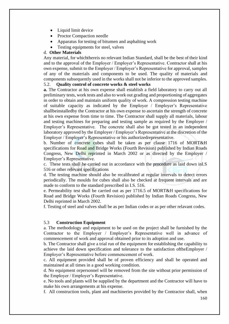
160
• Liquid limit device
• Proctor Compaction needle
• Apparatus for testing of bitumen and asphalting work
• Testing equipments for steel, valves
d. Other Materials
Any material, for whichthereis no relevant Indian Standard, shall be the best of their kind
and to the approval of the Employer / Employer’s Representative. Contractor shall at his
own expense, submit to the Employer / Employer’s Representative for approval, samples
of any of the materials and components to be used. The quality of materials and
components subsequently used in the works shall not be inferior to the approved samples.
5.2. Quality control of concrete works & steel works
a. The Contractor at his own expense shall establish a field laboratory to carry out all
preliminary tests, work tests and also to work out grading and proportioning of aggregates
in order to obtain and maintain uniform quality of work. A compression testing machine
of suitable capacity as indicated by the Employer / Employer’s Representative
shallbeinstalledby the Contractor at his own expense to ascertain the strength of concrete
at his own expense from time to time. The Contractor shall supply all materials, labour
and testing machines for preparing and testing sample as required by the Employer /
Employer’s Representative. The concrete shall also be got tested in an independent
laboratory approved by the Employer / Employer’s Representative at the discretion of the
Employer / Employer’s Representative or his authorizedrepresentative.
b. Number of concrete cubes shall be taken as per clause 1716 of MORT&H
specifications for Road and Bridge Works (Fourth Revision) published by Indian Roads
Congress, New Delhi reprinted in March 2002 or as directed by the Employer /
Employer’s Representative.
c. These tests shall be carried out in accordance with the procedure as laid down inI.S
516 or other relevant specifications
d. The testing machine should also be recalibrated at regular intervals to detect errors
periodically. The moulds for cubes shall also be checked at frequent intervals and are
made to conform to the standard prescribed in I.S. 516.
e. Permeability test shall be carried out as per 1716.5 of MORT&H specifications for
Road and Bridge Works (Fourth Revision) published by Indian Roads Congress, New
Delhi reprinted in March 2002.
f. Testing of steel and valves shall be as per Indian codes or as per other relavant codes.
5.3 Construction Equipment
a. The methodology and equipment to be used on the project shall be furnished by the
Contractor to the Employer / Employer’s Representative well in advance of
commencement of work and approval obtained prior to its adoption and use.
b. The Contractor shall give a trial run of the equipment for establishing the capability to
achieve the laid down specification and tolerance to the satisfaction oftheEmployer /
Employer’s Representative before commencement of work.
c. All equipment provided shall be of proven efficiency and shall be operated and
maintained at all times in a good working condition.
d. No equipment orpersonnel will be removed from the site without prior permission of
the Employer / Employer’s Representative.
e. No tools and plants will be supplied by the department and the Contractor will have to
make his own arrangements at his expense.
f. All construction tools, plant and machineries provided by the Contractor shall, when

161
brought to the site, be deemed to be exclusively intended for the construction and
completion of this work and the Contractor shall not remove the same or any part thereof
(save for the purpose of moving it from one part of the site to another) without the written
permission of the Employer / Employer’s Representative.
g. Incase concrete is procured from Ready Mixed Concrete (RMC) plants, the
contractorhasto obtain prior approval of the Employer / Employer’s Representative.
Quality controlling at Batching Plant has tobecarriedout by the Contractor at his own
cost.
162
Section - 6: Supplementary Specifications
163
SECTION – VI
Supplementary Specifications Preamble
This section contains the specifications for proposed work and shall be read in
conjunction with the various other sections forming the contract namely Notification
Inviting Applications, Instructions to Tenderers, General Conditions, Special Conditions,
Drawings and other related documents mentioned in this Tender Document together with
any Addendum issued thereto.
General Specifications: As mentioned in Section-IV of Volume-II
Supplementary Specifications: As mentioned in Section-IVof Volume- II

164
Section - 7: List of Approved Makes
165
SECTION – VII
List of Approved Makes
Sl
.
N
o.
Item/Equip
ment
Specified Makes
Pipes
1 DI Pipes Jindal Saw/TATA Metaliks/Kubota/Electro steel
2 DI Fitting/ Specials Jindal /Bharat Industrial Corporation/Oriental
Castings/Electro steel Castings/TISCO/Kejriwal Casting
3 HDPE/MDPE Pipes Jain Irrigation /Kimplas/Timeplast/Duraline
4 HDPE Fittings Kimplas /George Fischer/Aviva/Presto
5 MS Pipes Essar Steel/ Surya Global steel tubes Pvt. Ltd./ Jindal/ Tata
or as per Finance Dept,Kerala State
6 PVC Pipes Supreme/Prince/Finolex
7 Dismantling Joints Bharat Industrial Corporation/Oriental Castings/Electro
Steel Castings/TISCO/Kejriwal Castings
Pumps, Motors
8 Centrifugal Water
Pump Sets
Kirloskar/Jyoti/M&P(WILO)/FBM(Pentair)/Aqua/WPIL/
KSB/Flow More
9 Motors Kirloskar/ Seimens/ABB
10 Switch fuses and
MCCB’s
L&T/English Electric/Siemens/Control and switch gear/
BhartiaCuttler& hammer/Crompton Greaves
11 Lighting Fixtures Philips/Bajaj/Crompton/Wipro
Valves and Gates
12 DI Resilient Soft
Seated Sluice Valve
FOURESS/IVC/KIRLOSKAR/VAG/TALIS/Durga/AVK
13 Butterfly Valve FOURESS/IVC/KIRLOSKAR/VAG/TALIS/Durga/AVK/
ADVANCE
14 Air Valve FOURESS/IVC/KIRLOSKAR/VAG/TALIS/Durga/AVK/
ADVANCE
15 Swing type non
return valves
IVC/ Glenfield/ VAG/ KBL
16 Ball Valves Jainson Industries/ L&T
Cranes
17 HOT Crane Brady & Morris Engineering Co./Hercules hoists
Ltd./Sharp Engineering Pvt. Ltd.
18 EOT Crane Eddy Cranes/Electromech/Consolidated Hoist/Brady &
Morris Engineering Co./Hercules Hoist Ltd./JAPS Project
19 Chain pulley block Safex/Brady & Morris Engineering Co./Hercules hoists
Ltd/Reva Engineering/Indef Engineering
Steel
20 Reinforcement
Steel/IS Joist
SAIL/VIZAG STEEL/TATA
21 Cement ACC/AMBUJA/ULTRATECH/LAFARGE/MALA
BAR or as per Finance Dept, Kerala State
166
l
Section - 8: Additional Specifications
167
SECTION – VIII
Additional Specifications
TABLE OF CONTENT
PART1 –GENERALSPECIFICATIONS
PART 2 – GENERAL (MATERIAL) SPECIFICATIONS
PART A – WATER PIPE LINESPECIFICATIONS
PART B –GENERALMECHANICALREQUIREMENTS
PART C –ROADRESTORATION
PART D–BUILDINGS/CIVIL
168
PART 1 – GENERAL SPECIFICATIONS
GENERAL
1.1Reference mentioned herein shall be applicable to all sections to the extent the context
permits and are intended to supplement the provisions in the particular section. In case
of any discrepancy/deviation, the provisions in the particular section shall take
precedence.
INTERPRETATIONS
2.1 The Employer/Engineer-in-charge shall be the sole deciding authority as to the
meaning, interpretation and implications for various provisions of the specifications. His
decision in writing shall be final.
2.2 Wherever any reference is made to any Indian Standard, it shall be taken as
reference to the latest edition with all amendments issued thereto. In the event of any
variation between the Kerala Detailed Standard Specifications, CPWD specifications and
the Indian Standard, the former shall take precedence over the latter.
2.3 In case the specification of an item is not available in this document or documents
specified in Clause no 2.2, Contractor shall be permitted to use following alternative
specification subject to the following conditions:
a. He shall demonstrate that the proposed specification conforms to any of the following
international Standards, Codes of Practice, Specifications, Guidelines, etc.
b. it shall delivering an equal or better product and shall fulfill the intentoftheproduct.
1. International standard organization (ISO)
2. British Standards
3. American Society for Testing of Materials (ASTM)
4. German Standards
5. Euro Codes
DEFINITIONS
The following terms and expressions in the specifications shall have the meaning or
implication hereby assigned to them unless otherwise specified elsewhere.
Contractor: The Contractor shall mean the individual or firm or company whether
incorporated or not undertaking the works and shall include the legal personal
representatives of such individual or the persons composing such firm or company, or the
successors of such individual or firm or company and the permitted assignees of such
individual or firm of company.
Engineer-in-Charge: The ‘Engineer-in-Charge’ means the Engineer officer who shall
supervise and be in-charge of the work and who shall sign the contract on behalf of the
President.
Site: The ‘site’ shall mean the land/ or other places on, in, into or through which the work
is to be executed under the contract or any adjacent land, path or street through which the
work is to be executed under the contract, or any adjacent land, path or street which may
be allotted or used for the purpose of carrying out the contract.
Store: The ‘store’ shall mean the place of issue of materials.
IS: The standards, specification and code of practices issued by the Bureau of Indian
Standards.
Best: The word ‘best’ when used shall mean that in the opinion of the Engineer-in-
Charge, there is no superior material/ article and workmanship obtainable in the market
and trade respectively. As far as possible the standard required shall be specified in
preference to the word ‘best’.
Department: ‘Department’ shall be KIIDC
169
Floor 1 is the lowest floor above the ground level in the building unless otherwise
specified in a particular case. The floors above floor 1 shall be numbered in sequence as
floor 2, floor 3 and so on. The number shall increase upwards.
Floor level: For floor 1, top level of finished floor shall be the floor level and for all other
floors above floor 1, top level of the structural slabs shall be the floor level.
Plinth level: Floor 1 level or 1.2 m above the ground level whichever is lower shall be the
plinth level.
3.1 Special Structures
For structures like retaining walls, wing walls, chimneys, overhead reservoirs/ tanks and
other elevated structures, where elevations/ heights above a defined datum level have not
been specified and identification of floors cannot be done as in case of building. Level, at
1.2 m above the ground level shall be the floor 1 level as well as plinth level. Level at a
height of 3.5 m above floor 1 level will be reckoned as floor 2 level and level at a height
of 3.5 m above the floor 2 level will be floor 3 level and so on, where the total height
above floor 1 level is not a whole number multiple of 3.5 metre. Top most floor level
shall be the next in sequence to the floor level below even if the difference in height
between the two upper most floor levels is less than 3.5 metres
FOUNDATION AND PLINTH
The work in foundation and plinth shall include:
For buildings: All works up to1.2 metreabove ground level or up to floor1 level whichever
is lower:
For abutments, piers and well steining: all works up to1.2 m above the bed level:
For retaining wall, wing walls, compound walls, chimneys, overhead reservoirs/ tanks
and other elevated structures: All works upto1.2 metreabovethe ground level:
For reservoirs/ tanks (other than overhead reservoirs/ tanks): All works up to 1.2
metreabove the ground level:
For basements: All works upto1.2 m above ground level or up tofloor1 level whichever
is lower.
Note: Specific provision shall be made in the estimate for such situations where the
foundation level is more than 3 (three) metre depth from the plinth for all types of
structures mentioned above.
MEASUREMENTS
5.1 In booking dimensions, the order shall be consistent and in the sequence of length,
width and height or depth or thickness.
5.2 Rounding off: Rounding off where required shall bedone in accordance with IS: 2-
1960. The number of significant places rounded in the rounded off value should be as
specified.
MATERIALS
6.1 Samples of all materials to be used on the work shall be got approved by the
contractor from the Engineer-in-Charge well in time. The approved samples duly
authenticated and sealed shall be kept in the custody of the Engineer-in-Charge till the
completion of the work. All materials to be provided by the contractor shall be brand new
and as per the samples approved by the Engineer-in-Charge.
6.2 Materials obtained by the contractor from the sources approved by the Department
shall be subjected to the Mandatory tests. Where such materials do not conform to the
relevant specifications, the matter shall be taken up by the Engineer-in-Charge for
appropriate action against the defaulters. In all such cases, necessary documents in
original and proof of payment relating to the procurement of materials shall
bemadeavailableby the contractor to the Engineer-in-Charge.
6.3All the Materials incorporated in the Works shall be the most suitable for the duty
170
concerned and shall be new and of first class commercial quality, free from imperfections
and selected for long life and minimum maintenance. These may be tested according to
relevant Indian Standards (IS) or International Standards Organization (ISO) standards
in qualified labs and certificates produced to the satisfaction of the Employer’s
Representative.
6.4 The objectives of the specifications given are to specify the details pertaining to the
designs, drawings, and selection of equipment or product. The equipment or product
supplied shall be of high standard of quality and best engineering practices and shall
comply with all currently applicable standards, regulationsand codes.
6.5 All necessary safety measures and precautions (including those laid down in the
various relevant Indian Standards) shall be taken as also of the work itself.
6.6 Thematerials, supplied by the client shall be deemed to be complying with the
specifications.
6.7 Contractor shall submit sample of the material and get written approval of the
Employer/Engineer – charge before placing the order. Any work executed without
approval of sample shall be deemed rejected.
6.8 All work shall be executed as per approved drawing only
6.9 Approval to any of the executed items for the work does not in any way relieve the
Contractor of his responsibility for the correctness, soundness and strength of the
structure as per the drawings and specifications.
6.10All works shall be carried out strictly as per detailed technical specification provided
in the tender. If not specified, the work shall be executed according to relevant applicable
IS codes and standard engineering practice. In such case decision of the Engineer-in-
charge shall be final and binding to the Contractor and in no case the Contractor will
claim any extra for the same.
6.11 If the specifications for a particular item are not given by the Employer, the Standard
Specifications of Kerala/CPWD specification/Indian standard shall be followed. In all the
conditions, direction of Engineer in charge shall be final binding upon the contractor.
6.12 Materials stored at site, depending upon the individual characteristics, shall be
protected from atmospheric effects due to rain, sun, wind and moisture to avoid
deterioration.
6.13 Materials like timber, paints etc. shall be stored in such a way that there may not be
any possibility of fire hazards. Inflammable materials and explosives shall be stored in
accordance with the relevant rules and regulations or as approved by Engineer-in-Charge
in writing so as to ensure desired safety during storage.
6.14 The unit weight of materials unless otherwise specified shallbereckoned as given in
IS: 1911-1967.
SAMPLES AND TESTS OF MATERIALS
All tests as required, both at the factory i.e. Factory Acceptance Test (FAT) before
dispatch, and at site after installation i.e. Site Acceptance Tests (SAT), shall be carried
out. Detailed Test reports and certificates shall be submitted.
The Contractor shall submit samples of such materials as may be required by Engineer in
charge and shall carry out the specified tests directed by KIIDC/ Engineer in charge at
the Site, at the supplier's premises or at a laboratory approved by KIIDC/ Engineer in
charge. All other incidental expenditure to be incurred for testing of samples e.g.
packaging, sealing transportation, loading, unloading etc. testing charges shall be borne
by the contractor.
Employer may appoint separate third party inspection for the material testing to ensure
the quality of the work. The Contractor shall replace the defective material as an outcome
of these tests.
171
Samples shall be submitted and tests carried out sufficiently early to enable further
samples to be submitted and tested if required by KIIDC/ Engineer in charge. The
Contractor shall give seven days' notice in writing of the date on which any of the
materials will be ready for testing or inspection at the supplier's premises or at a laboratory
approved by Employer. Representative of Employer shall attend the test at the appointed
place within seven days of the said date on which the materials are expected to be ready
for testing or inspection according to the Contractor, failing which the test may proceed
in his absence unless instructed by Employer to carry out such a test on a mutually agreed
date in his presence. Prior to testing, all relevant documentation and sufficient briefing
about the tests shall be given to Employer’s Representatives who would witness the
testing. The Contractor shall in any case submit to KIIDC/ Engineer in charge within
seven days of every test such number of certified copies (minimum six) of the test results
as KIIDC/ Engineer in charge may require. Approval by KIIDC/ Engineer in charge as to
the placing of orders for materials or as to samples or tests shall not prejudice any powers
under the Contract. The provisions of this clause shall also apply fully to materials
supplied under any nominated sub‐contract.
SAFETY IN CONSTRUCTION
8.1 The contractor shall employ only such methods of construction, tools and plant as
are appropriate for the type of work or as approved by Engineer-in-Charge in writing.
8.2 The contractor shall take all precautions and measures to ensure safety of works and
workman and shall be fully responsible for the same. Safety pertaining to construction
works such as excavation, centering andshuttering, trenching, blasting, demolition,
electric connections, scaffolds, ladders, working platforms, gangway, mixing of
bituminous materials, electric and gas welding, use of hoisting and construction
machinery shall be governed by CPWD safety code, relevant safety codes and the
direction of Engineer-in- Charge.
ABBREVIATIONS
The following abbreviations wherever theyappear in the specifications shall have the
meaning or implication hereby assigned to them:
Mm- Millimetre
Cm - Centimetre
M - Metre
Km - Kilometre
Mm2/sqmm - Square Milimetre
Cm2/sqcm - Square centimetre
Dm2/sqdm - Square decimetre
M2/sqm - Square metre
Cm3/cubic cm - Cubic centimetre
Dm3/cubic dm- Cubic decimetre
M3/cum - Cubic metre
Ml - Milli litre
Kl - Kilo litre
Gm - Gram
Kg - Kilogram
Q - Quintal
T - Tonne
FPSsystem - Foot pound second system
°C - Degree Celsius temperature
Fig - Figure
Re/Rs - Rupee/Rupees
172
No - Number
Dia - Diameter
AC - Asbestos cement
CI - Cast Iron
GC - Galvanized corrugated
GP - Galvanized plain
GI- Galvanized Iron
PVC - Polyvinylchloride
RCC - Reinforced cement concrete
SWG - Standard wire Gauge
CAPEX Capital Expenditure
OPEX Operating Expenditure
KPI Key Performance Indicator
BHN Brinell Hardness number
HDPE High Density Poly Ethylene
LTHS Long Term Hydrostatic Strength
MFR Melt Flow Rate
OD Outer Diameter
RT Radiography Test
EPDM Ethylene Propylene Diene Monomer (A synthetic Rubber)
SBR Styrene Butadine Rubber
DI Ductile Iron
PE Poly Ethylene
ISO International Organization for Standardization
AWWA American Water Works Association
NPSH Net positive Suction Head
WMM Wet Mix Macadam
PIU Project Implementation Unit
IBM International Business Machines
EN European Norms
NBR Nitrile Butadine Number
VFD Variable Frequency Drive
173
PART 2 - GENERAL (MATERIAL) SPECIFICATIONS
1.1 GENERAL
Materials to be used in the work shall conform to the specifications mentioned on the
drawings, the requirements laid down in this section and specifications for relevant items
of work covered under these specifications.
If any material, not covered in these specifications, is required to be used in the work, it
shall conform to relevant Indian Standards, if there are any, or to the requirements
specified by the Engineer.
1.2 SOURCES OF MATERIAL
The Contractor shall notify the Engineer of his proposed sources of materials prior to
delivery. If it is found after trial that sources of supply previously approved do not
produce uniform and satisfactory products, or if the product from any other source proves
unacceptable at any time, the Contractor shall furnish acceptable material from other
sources at his own expense.
BRICKS
The bricks shall be modular type class designation – 25, kiln-burnt bricks of regular and
uniform size, shape and colour, well burnt throughout. They shall be free from cracks or
other flaws viz. lumps of lime, laminations, soluble salts causing efflorescence, air-holes
which may in any way impair their strength durability, appearance etc. They shall give a
clear metallic ringing sound when struck together.
After absorbing water the bricks shall not exceed 20% of their dry weight as per IS: 1077
- 1992. According to IS: 1077 - 1992 crushing load shall not be less than 25 Kg. /Sq. Cm.
Samples of bricks shall also be subjected to the following tests:
Dimensional tolerance.
Water absorption.
Efflorescence.
Compressive strength.
STONES
Stones shall be of the type specified. It shall be hard, sound, and free from cracks, decay
and weathering and shall be freshly quarried from an approved quarry. Stone with round
surface shall not be used.
The stones, when immersed in water for 24 hours, shall not absorb water by more than 5
per cent of their dry weight when tested in accordance with IS: 1124 -1972.
The length of stones shall not exceed 3 times its height nor shall they be less than twice
its height plus one joint. No stone shall be less in width than the height and width on the
base shall not be greater than three-fourth of the thickness of the wall nor less than 150
mm.
CAST IRON
Cast iron shall conform to IS: 210-2009. The grade number of the material shall not be
less than 14.
CEMENT
Cement to be used in the works shall be any of the following types with the prior approval
of the Engineer:
Ordinary Portland cement, 43 Grade, conforming to IS: 8112-1989.
Rapid Hardening Portland Cement, conforming to IS: 8041-1990.
SulphateResistant Portland cement, conforming to IS: 12330-1988.
Cement conforming to IS: 8112-1989 and IS: 12269-1987 may be used provided the
minimum cement content mentioned elsewhere from durability considerations is not

174
reduced. From strength considerations, these cements shall be used with a certain caution
as high early strengths of cement in the 1 to 28–day range can be achieved by finer
grinding and higher constituent ratio of C3S/C2S, where C3S is Tricalcium Silicate and
C2S is Di calcium Silicate. In such cements, the further growth of strength beyond say 4
weeks may be much lower than that traditionally expected. Therefore, further strength
tests shall be carried out for 56 and 90 days to fine tune the mix design from strength
considerations.
Cement conforming to IS: 12330-1988 shall be used when sodium sulphateand
magnesium sulphateare present in large enough concentration to be aggressive to
concrete. The recommended threshold values as per IS: 456-2000 are sulphate
concentration in excess of0.2 per cent in soil sub-strata or300 ppm (0.03 per cent) in
ground water. Tests to confirm actual values of sulphateconcentration are essential
whenthestructure is located near the sea coast, chemical factories, and agricultural land
using chemical fertilizers and sites where there are effluent discharges or where soluble
sulphate bearing ground water level is high. Cement conforming to IS: 12330-1988 shall
be carefully selected from strength considerations to ensure that the minimum required
design strength can be achieved without exceeding the maximum permissible cement
content of 540 kg/cu.mofconcrete.
Cement conforming to IS: 8041-1990 shall be used only for precast concrete products
after specific approval of the Engineer.
Total chloride content in cement shall in no case exceed 0.05 per cent by mass of cement.
Also, total sulphur content calculated as sulphuric anhydride (SO3) shall in no case
exceed 2.5 per cent and 3.0 per cent when tri-calcium aluminate percent by mass is up to
5 or greater than 5 respectively.
COARSE AGGREGATES
For plain and reinforced cement concrete (PCC and RCC) works, coarse aggregate shall
consist of clean, hard, strong, dense, non-porous and durable pieces of crushed stone,
crushed gravel, natural gravel or a suitable combination thereof or other approved inert
material. They shall not contain pieces of disintegrated stones, soft, flaky, elongated
particles, salt, alkali, vegetable matter or other deleterious materials in such quantities as
to reduce the strength and durability of the concrete, or to attack the steel reinforcement.
Coarse aggregate having positive alkali-silica reaction shall not be used. All coarse
aggregates shall conform to IS: 383 - 1970 and tests for conformity shall be carried out
as per IS: 2386 -1963, Parts I to VIII.
The contractor shall submit for the approval of the Engineer, the entire information
indicated in Appendix A ofIS: 383-1970.
The maximum value for flakiness index for coarse aggregate shall not exceed 35 per cent.
The coarse aggregate shall satisfy the following requirements of grading:
REQUIREMENTS OF COARSE AGGREGATE
IS
Sieve
Size
Per cent Weight Passing the Sieve
40 mm 20 mm 12.5 mm
63 mm 100 - -
40 mm 95-100 100 -
20 mm 30-70 95-100 100
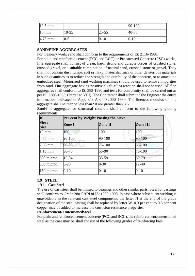
175
12.5 mm - - 90-100
10 mm 10-35 25-55 40-85
4.75 mm 0-5 0-10 0-10
SAND/FINE AGGREGATES
For masonry work, sand shall conform to the requirements of IS: 2116-1980.
For plain and reinforced cement (PCC and RCC) or Pre-stressed Concrete (PSC) works,
fine aggregate shall consist of clean, hard, strong and durable pieces of crushed stone,
crushed gravel, or a suitable combination of natural sand, crushed stone or gravel. They
shall not contain dust, lumps, soft or flaky, materials, mica or other deleterious materials
in such quantities as to reduce the strength and durability of the concrete, or to attack the
embedded steel. Motorized sand washing machines should be used to remove impurities
from sand. Fine aggregate having positive alkali-silica reaction shall not be used. All fine
aggregates shall conform to IS: 383-1980 and tests for conformity shall be carried out as
per IS: 2386-1963, (Parts I to VIII). The Contractor shall submit to the Engineer the entire
information indicated in Appendix A of IS: 383-1980. The fineness modulus of fine
aggregate shall neither be less than2.0 nor greater than 3.5.
Sand/fine aggregate for structural concrete shall conform to the following grading
requirements:
IS
Sieve
Size
Per cent by Weight Passing the Sieve
Zone I Zone II Zone III
10 mm 100 100 100
4.75 mm 90-100 90-100 90-100
2.36 mm 60-95 75-100 85-100
1.18 mm 30-70 55-90 75-100
600 micron 15-34 35-59 60-79
300 micron 5-20 8-30 12-40
150 micron 0-10 0-10 0-10
1.9 STEEL
1.9.1 Cast Steel
The use of cast steel shall be limited to bearings and other similar parts. Steel for castings
shall conform to Grade 280-520N of IS: 1030-1998. In case where subsequent welding is
unavoidable in the relevant cast steel components, the letter N at the end of the grade
designation of the steel casting shall be replaced by letter W. 0.3 per cent to 0.5 per cent
copper may be added to increase the corrosion resistance properties.
Reinforcement/ UntensionedSteel
For plain and reinforced cement concrete (PCC and RCC), the reinforcement/untensioned
steel as the case may be shall consist of the following grades of reinforcing bars.
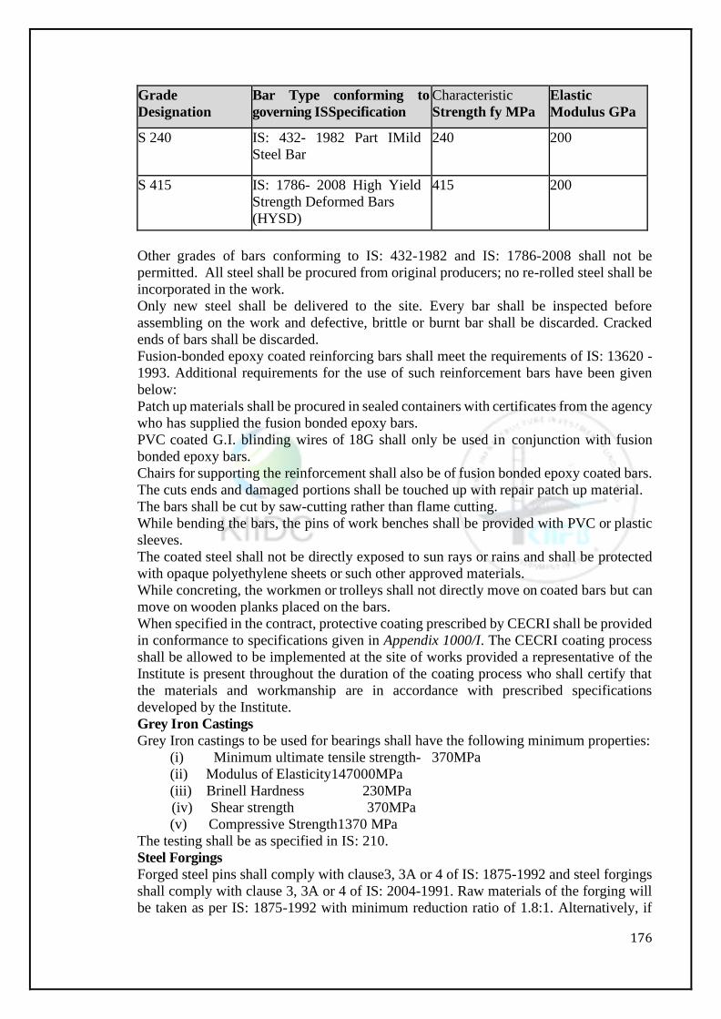
176
Grade
Designation
Bar Type conforming to
governing ISSpecification
Characteristic
Strength fy MPa
Elastic
Modulus GPa
S 240 IS: 432- 1982 Part IMild
Steel Bar
240 200
S 415 IS: 1786- 2008 High Yield
Strength Deformed Bars
(HYSD)
415 200
Other grades of bars conforming to IS: 432-1982 and IS: 1786-2008 shall not be
permitted. All steel shall be procured from original producers; no re-rolled steel shall be
incorporated in the work.
Only new steel shall be delivered to the site. Every bar shall be inspected before
assembling on the work and defective, brittle or burnt bar shall be discarded. Cracked
ends of bars shall be discarded.
Fusion-bonded epoxy coated reinforcing bars shall meet the requirements of IS: 13620 -
1993. Additional requirements for the use of such reinforcement bars have been given
below:
Patch up materials shall be procured in sealed containers with certificates from the agency
who has supplied the fusion bonded epoxy bars.
PVC coated G.I. blinding wires of 18G shall only be used in conjunction with fusion
bonded epoxy bars.
Chairs for supporting the reinforcement shall also be of fusion bonded epoxy coated bars.
The cuts ends and damaged portions shall be touched up with repair patch up material.
The bars shall be cut by saw-cutting rather than flame cutting.
While bending the bars, the pins of work benches shall be provided with PVC or plastic
sleeves.
The coated steel shall not be directly exposed to sun rays or rains and shall be protected
with opaque polyethylene sheets or such other approved materials.
While concreting, the workmen or trolleys shall not directly move on coated bars but can
move on wooden planks placed on the bars.
When specified in the contract, protective coating prescribed by CECRI shall be provided
in conformance to specifications given in Appendix 1000/I. The CECRI coating process
shall be allowed to be implemented at the site of works provided a representative of the
Institute is present throughout the duration of the coating process who shall certify that
the materials and workmanship are in accordance with prescribed specifications
developed by the Institute.
Grey Iron Castings
Grey Iron castings to be used for bearings shall have the following minimum properties:
(i) Minimum ultimate tensile strength- 370MPa
(ii) Modulus of Elasticity147000MPa
(iii) Brinell Hardness 230MPa
(iv) Shear strength 370MPa
(v) Compressive Strength1370 MPa
The testing shall be as specified in IS: 210.
Steel Forgings
Forged steel pins shall comply with clause3, 3A or 4 of IS: 1875-1992 and steel forgings
shall comply with clause 3, 3A or 4 of IS: 2004-1991. Raw materials of the forging will
be taken as per IS: 1875-1992 with minimum reduction ratio of 1.8:1. Alternatively, if
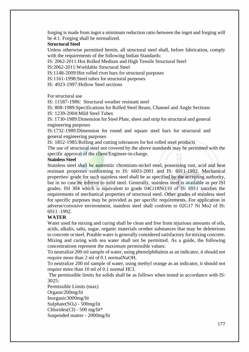
177
forging is made from ingot a minimum reduction ratio between the ingot and forging will
be 4:1. Forging shall be normalized.
Structural Steel
Unless otherwise permitted herein, all structural steel shall, before fabrication, comply
with the requirements of the following Indian Standards:
IS: 2062-2011:Hot Rolled Medium and High Tensile Structural Steel
IS:2062-2011:Wieldable Structural Steel
IS:1148-2009:Hot rolled rivet bars for structural purposes
IS:1161-1998:Steel tubes for structural purposes
IS: 4923-1997:Hollow Steel sections
For structural use
IS: 11587-1986: Structural weather resistant steel
IS: 808-1989:Specifications for Rolled Steel Beam, Channel and Angle Sections
IS: 1239-2004:Mild Steel Tubes
IS: 1730-1989:Dimension for Steel Plate, sheet and strip for structural and general
engineering purposes
IS:1732-1989:Dimension for round and square steel bars for structural and
general engineering purposes
IS: 1852-1985:Rolling and cutting tolerances for hot rolled steel products
The use of structural steel not covered by the above standards may be permitted with the
specific approval of the client/Engineer-in-charge.
Stainless Steel
Stainless steel shall be austenitic chromium-nickel steel, possessing rust, acid and heat
resistant properties conforming to IS: 6603-2001 and IS: 6911-1992. Mechanical
properties/ grade for such stainless steel shall be as specified by the accepting authority,
but in no case be inferior to mild steel. Generally, stainless steel is available as per ISI
grades. ISI 304 which is equivalent to grade 04Cr18Ni110 of IS: 6911 satisfies the
requirements of mechanical properties of structural steel. Other grades of stainless steel
for specific purposes may be provided as per specific requirements. For application in
adverse/corrosive environment, stainless steel shall conform to 02G17 Ni Mo2 of IS:
6911 -1992.
WATER
Water used for mixing and curing shall be clean and free from injurious amounts of oils,
acids, alkalis, salts, sugar, organic materials orother substances that may be deleterious
to concrete or steel. Potable water is generally considered satisfactory for mixing concrete.
Mixing and curing with sea water shall not be permitted. As a guide, the following
concentrations represent the maximum permissible values:
To neutralize 200 ml sample of water, using phenolphthalein as an indicator, it should not
require more than 2 ml of 0.1 normalNaOH.
To neutralize 200 ml sample of water, using methyl orange as an indicator, it should not
require more than 10 ml of 0.1 normal HCI.
The permissible limits for solids shall be as follows when tested in accordance with IS:
3025:
Permissible Limits (max)
Organic200mg/lit
Inorganic3000mg/lit
Sulphate(SO4) - 500mg/lit Chlorides(CI) - 500 mg/lit*
Suspended matter - 2000mg/lit
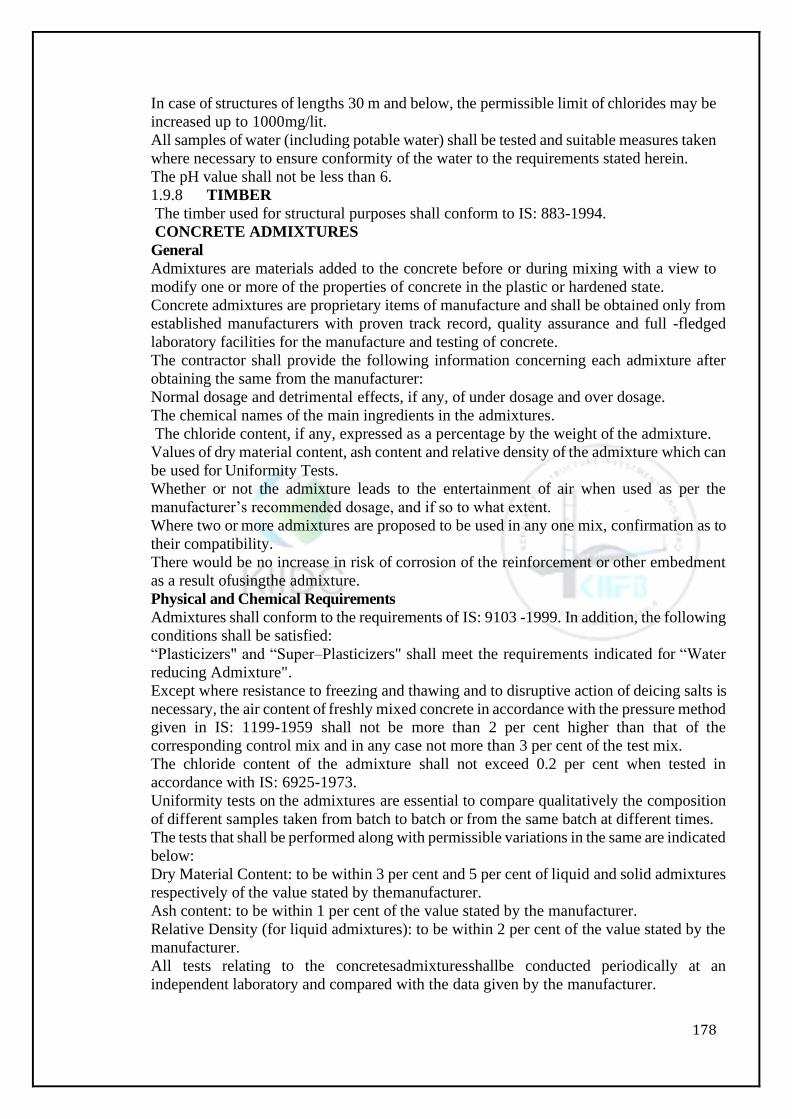
178
In case of structures of lengths 30 m and below, the permissible limit of chlorides may be
increased up to 1000mg/lit.
All samples of water (including potable water) shall be tested and suitable measures taken
where necessary to ensure conformity of the water to the requirements stated herein.
The pH value shall not be less than 6.
1.9.8 TIMBER
The timber used for structural purposes shall conform to IS: 883-1994.
CONCRETE ADMIXTURES
General
Admixtures are materials added to the concrete before or during mixing with a view to
modify one or more of the properties of concrete in the plastic or hardened state.
Concrete admixtures are proprietary items of manufacture and shall be obtained only from
established manufacturers with proven track record, quality assurance and full -fledged
laboratory facilities for the manufacture and testing of concrete.
The contractor shall provide the following information concerning each admixture after
obtaining the same from the manufacturer:
Normal dosage and detrimental effects, if any, of under dosage and over dosage.
The chemical names of the main ingredients in the admixtures.
The chloride content, if any, expressed as a percentage by the weight of the admixture.
Values of dry material content, ash content and relative density of the admixture which can
be used for Uniformity Tests.
Whether or not the admixture leads to the entertainment of air when used as per the
manufacturer’s recommended dosage, and if so to what extent.
Where two or more admixtures are proposed to be used in any one mix, confirmation as to
their compatibility.
There would be no increase in risk of corrosion of the reinforcement or other embedment
as a result ofusingthe admixture.
Physical and Chemical Requirements
Admixtures shall conform to the requirements of IS: 9103 -1999. In addition, the following
conditions shall be satisfied:
“Plasticizers" and “Super–Plasticizers" shall meet the requirements indicated for “Water
reducing Admixture".
Except where resistance to freezing and thawing and to disruptive action of deicing salts is
necessary, the air content of freshly mixed concrete in accordance with the pressure method
given in IS: 1199-1959 shall not be more than 2 per cent higher than that of the
corresponding control mix and in any case not more than 3 per cent of the test mix.
The chloride content of the admixture shall not exceed 0.2 per cent when tested in
accordance with IS: 6925-1973.
Uniformity tests on the admixtures are essential to compare qualitatively the composition
of different samples taken from batch to batch or from the same batch at different times.
The tests that shall be performed along with permissible variations in the same are indicated
below:
Dry Material Content: to be within 3 per cent and 5 per cent of liquid and solid admixtures
respectively of the value stated by themanufacturer.
Ash content: to be within 1 per cent of the value stated by the manufacturer.
Relative Density (for liquid admixtures): to be within 2 per cent of the value stated by the
manufacturer.
All tests relating to the concretesadmixturesshallbe conducted periodically at an
independent laboratory and compared with the data given by the manufacturer.
179
STORAGE OFMATERIALS
General
All materials may be stored at proper places so as to prevent their deterioration or intrusion
by foreign matter and to ensure their satisfactory quality and fitness for the work. The
storage space must also permit easy inspection, removal and restorageofthe materials. All
such materials even though stored in approved godowns/places, must be subjected to
acceptance test prior to their immediate use.
1.10.2 Brick
Bricks shall not be dumped at site. They shall be stacked in regular tiers as they are
unloaded, to minimize breakage and defacement. The supply of bricks shall be available at
site at any time. Bricks selected for use in different situations shall be stacked separately.
Aggregates
Aggregate stockpiles may be made on ground that is denuded of vegetation, is hard and
well drained. If necessary, the ground shall be covered with 50 mm plank.
Coarse aggregates, unless otherwise agreed bytheEngineer in writing shall be delivered to
the site in separate sizes (2 sizes when nominal size is 25 mm or less and 3 sizes when the
nominal size is 32 mm or more). Aggregates placed directly on the ground shall not be
removed from the stockpile within 30 cm of the ground until the final cleaning up of the
work, and then only the clean aggregate will be permitted to be used.
In the case of line aggregates, these shall be deposited at the mixing site not less than 8
hours before use and shall have been tested and approved by the Engineer.
Cement
Cement shall be transported, handled and stored on the site in such a manner as to avoid
deterioration or contamination. Cement shall be stored above ground level in perfectly dry
and water–tight sheds and shall be stacked not more than eight bags high. Wherever bulk
storage containers are used their capacity should be sufficient to cater to the requirement
at site and should be cleaned at least once every 3 to 4 months.
Each consignment shall be stored separately so that it may be readily identified and
inspected and cement shall be used in the sequence in which it is delivered at site. Any
consignment or part of a consignment of cement which had deteriorated in any way, during
storage, shall not be used in the works and shall be removed from the site by the Contractor
without charge to the Employer.
The Contractor shall prepare and maintain proper records on site in respect of delivery,
handling, storage and use of cement and these records shall be available for inspection by
the Engineer at all times.
The Contractor shall make a monthly return to the Engineer on the date corresponding to
the interim certificate date, showing the quantities of cement received and issued during
the month and in stock at the end of the month.
Reinforcement/UntensionedSteel
The reinforcement bars, when delivered on the job, shall be stored above the surface of the
ground upon platforms, skids, or other supports, and shall be protected from mechanical
injury and from deterioration by exposure.
Pre-stressing Materials
All pre-stressing steel, sheathing, anchorages and sleeves or coupling must be protected
during transportation, handling and storage. The pre-stressing steel, sheathing and other
accessories must be stored under cover from rain or damp ground and protected from the
ambient atmosphere if it is likely to be aggressive. Storage at site must be kept to the
absolute minimum.
Tendon:
Wire, strand and bar from which tendons are to be fabricated shall be stored about 300 mm
180
above the ground in a suitably covered and closed space so as to avoid direct climatic
influences and to protect them from splashes from any other materials and from the cutting
operation of an oxy–acetylene torch or arc welding process in the vicinity. Under no
circumstances, tendon material shall be subjected to any welding operation or on site heat
treatment or metallic coating such as galvanizing. Storage facilities and the procedures for
transporting material into or out of store shall be such that the material does not become
kinked or notched. Wire or strand shall be stored in large diameter coils which enable the
tendons to be laid out straight. As a guide, for wires above 5 mm dia, coils of about 2 m dia
without breaks or joints shall be obtained from manufacturer andstored. Protective
wrapping for tendons shall be chemically neutral. All pre-stressing steel must be provided
withtemporaryprotection during storage.
Anchorage Components:
The handling and storing procedures shall maintain the anchorage components in a
condition in which they can subsequently perform their function to an adequate degree.
Components shall be handled and stored so that mechanical damage and detrimental
corrosion are prevented. The corrosion of the gripping and securing system shall be
prevented. The use of correctly formulated oils and greases or of other corrosion preventing
material is recommended where prolonged storage is required. Such protective material
shall be guaranteed by the producer to be non–aggressive and non–degrading.
Pre-stressing steel shall be stored in a closed store having single door with double locking
arrangements and no windows. Also, the air inside the store shall be kept dry as far as
possible by using various means to the satisfaction of the Engineer. Also, instrument
measuring the air humidity shall be installed inside the store. This is with a view to
eliminating the possibility of initial rusting of pre-stressing steel during storage. The pre-
stressing steel shall be coated with water solvable grease. The pre-stressing steel should
beabsolutely clean and without any signs of rust.
All pre-stressing steel shall be stored at least 30 cm above ground level and it shall be
invariably wrapped by protective cover of tar paper or polythene or any other approved
material. The Contractor should see that pre-stressing steel shall be used within 3 months
of its manufacture. He should chalk out his programmein this respect precisely, so as to
avoid initial corrosion before placing in position.
Water
Water shall be stored in containers/tanks covered at top and cleaned at regular intervals in
order to prevent intrusion by foreign matter or growth of organic matter. Water from
shallow, muddy or marshy surface shall not be permitted. The intake pipe shall be enclosed
to exclude silt, mud, grass and other solid materials and there shall be a minimum depth of
0.60 m of water below the intake at all times.
TESTS AND STANDARD OF ACCEPTANCE
All materials, even though stored in an approved manner shall be subjected to an
acceptance test prior to their immediate use.
Independent testing of cement for every consignment shall be done by the Contractor at
site in the laboratory approved by the Engineer before use. Any cement with lower quality
than those shown in manufacturer’s certificate shall be debarred from use. In case of
imported cement, the same series of tests shall be carried out before acceptance.
Testing and Approval of Material
The Contractor shall furnish test certificates from the manufacturer/supplier of materials
along with each batch of material(s) delivered to site.
The Contractor shall set up a field laboratory with necessary equipment for testing of all
materials, finished products used in the construction as per requirements of conditions of
contract and the relevant specifications. The testing of all the materials shall be carried out
181
by the Engineer or his representative for whom the Contractor shall make all the necessary
arrangements and bear the entire cost.
Tests which cannot be carried out in the field laboratory have to be got done at the
Contractor’s cost at any recognized laboratory/testing establishments approvedby the
Engineer.
Sampling of Materials
Samples provided to the Engineer or his representatives for their retention are to be in
labeled boxes suitable for storage.
Samples required for approval and testing must be supplied well in advance by at least 48
hours or minimum period required for carrying out relevant tests to allow for testing and
approval. Delay to works arising from the late submission of samples will not be acceptable
as a reason for delay in the completion of the works.
If materials are brought from abroad, the cost of sampling/testing whether in India or
abroad shall be borne by the Contractor.
Rejection of Materials not conforming to the Specifications
Any stack or batch of material(s) of which sample(s) does not conform to the prescribed
tests and quality shall be rejected by the engineer or his representative and such materials
shall be removed from site by the contractor at his own cost. Such rejected materials shall
not be made acceptable by any modifications.
Testing and Approval of Plant and Equipment
All plants and equipment used for preparing, testing and production of materials for
incorporation into the permanent works shall be in accordance with manufacturer’s
specifications and shall be got approved by the Engineer before use.
STEEL REINFORCEMENT
Description
This work shall consist of furnishing and placing coated or uncoated mild steel or high
strength deformed reinforcement bars (untensioned) of the shape and dimensions shown
on the drawings and conforming to these Specifications or as approved by the Engineer.
General
Steel for reinforcement shall meet with the requirements of Section 1000 under road work
specification. Reinforcements may be either mild steel/medium tensile steel or high
strength deformed bars. They may be uncoated or coated with epoxy or with approved
protective coatings.
Protection of Reinforcement
Uncoated reinforcing steel shall be protected from rusting or chloride contamination.
Reinforcements shall be free from rust, mortar, loose mill scale, grease, oilorpaints. This
may be ensured either by using reinforcement fresh from the factory or thoroughly cleaning
all reinforcement to remove rust using any suitable method such as sand blasting,
mechanical wire brushing, etc., as directed by the Engineer. Reinforcements shall be stored
on block, racksorplatforms and above the ground in a clean and dry condition and shall be
suitably marked to facilitate inspection and identification.
Portions of uncoated reinforcing steel and dowels projecting from concrete shall be
protected within one week after initial placing of concrete with a brush coat of neat cement
mixed with water to a consistency of thick paint. This coating shall be removed by lightly
tapping with a hammer or other tool not more than one week before placing of the adjacent
pour of concrete. Coated reinforcing steel shall be protected against damage to the coating.
If the coating on the bars is damaged duringtransportation or handling and cannot be
repaired, the same shall be rejected.
Bending of Reinforcement
Bar bending schedule shall be furnished by the Contractor and got approved by the
182
Engineer before start of work. Reinforcing steel shall conform to the dimensions and shapes
given in the approved Bar Bending Schedules. Bars shall be bent cold to the specified shape
and dimensions or as directed by the Engineer using a proper bar bender, operated by hand
or power to obtain the correct radii of bends and shape. Bars shall not be bent or
straightened in a manner that will damage the parent material or the coating. Bars bent
during transport or handling shall be straightened before being used on work and shall not
be heated to facilitate straightening.
Placing of Reinforcement
The reinforcement cage should generally be fabricated in the yard at ground level and then
shifted and placed in position. The reinforcement shall be placed strictly in accordance with
the drawings and shall be assembled in position only when the structure is otherwise ready
for placing of concrete. Prolonged time gap between assembling of reinforcements and
casting of concrete, which may result in rust formation on the surface, shall not be
permitted.
Reinforcement bars shall be placed accurately in position as shown on the drawings. The
bars, crossing one another shall be tied together at every intersection with binding wire
(annealed), conforming to IS: 280-2006 to make the skeleton of the reinforcement rigid
such that the reinforcement does not get displaced during placing of concrete, or any other
operation. The diameter of binding wire shall not be less than 1mm.
Bars shall be kept in position usually by the following methods:
(i) In case of beam and slab construction, industrially produced polymer cover blocks of
thickness equal to the specified cover shall be placed between the bars and formwork
subject to satisfactory evidence that the polymer composition is not harmful to concrete
and reinforcement. Cover blocks made of concrete may be permitted by the Engineer,
provided they have the same strength and specification as those of the member.
(ii) In case of dowels for columns and walls, the vertical reinforcement shall be kept in
position by means of timber templates with slots cut in them accurately, or with cover
blocks tied to the reinforcement. Timber templates shall be removed after the concreting
has progressed up to a level just below their location.
(iii) Layers of reinforcements shall be separated by spacer bars at approximately one metre
intervals. The minimum diameter of spacer bars shall be 12 mm or equal to maximum size
of main reinforcement or maximum size of coarse aggregate, whichever is greater.
Horizontal reinforcement shall not be allowed to sag between supports.
(iv) Necessary stays, blocks, metal chairs, spacers, metal hangers, supporting wires etc., or
other subsidiary reinforcement shall be provided tofixthereinforcements firmly in its
correct position.
(v) Use of pebbles, broken stone, metal pipe, brick, mortar orwooden blocks etc., as
devices for positioning reinforcement shall not be permitted.
(d) Bars coated with epoxy or any other approved protective coating shall be placed on
supports that do not damage the coating. Supports shall be installed in a manner such that
planes of weakness are not created in hardened concrete. The coated reinforcing steel shall
be held in place by use of plastic or plastic-coated binding wires especially manufactured
for the purpose. Reference shall be made to Section 1000 for other requirements.
(e) Placing and fixing of reinforcement shall be inspected and approved by the Engineer
before concrete is deposited.
BAR SPLICES
Lapping
All reinforcement shall be furnished in full lengths as indicated on the drawing. No
splicing of bars, except where shown on the drawing, will be permitted without approval
183
of the Engineer. The lengths of the splice shall be as indicated on drawing or as approved
by the Engineer. Where practicable, overlapping bars shall not touch each other, and shall
be kept apart by 25 mm or1.25times the maximum size of coarse aggregate, whichever
is greater.Ifthis is not feasibleoverlappingbarsshallbebound with annealedsteel binding
wire, not less than 1 mm diameter and twisted tight in such a manner as to maintain
minimum clear cover to the reinforcement from the concrete surface. Lapped splices shall
be staggered or located at points, along the span where stresses are low.
Welding
Splicing by welding of reinforcement will be permitted only if detailed on the drawing or
approved by the Engineer. Weld shall develop an ultimate strength equal to or great than
that of the bars connected.
While welding may be permitted for mild steel reinforcing bars conforming to IS: 432 -
1982, welding of deformed bars conforming to IS: 1786-2008 shall in general be
prohibited. Welding may be permitted in case of bars other than S 240 grade including
special welding grade of S 415 grade bars conforming to IS: 1786-2008, for which
necessary chemical analysis has been secured and the carbon equivalent (CE) calculated
from the chemical composition using the formula:
CE = C + (Mn/6) + (Cr+Mg+V)/5 + (Ni + Cu)/15 is 0.4 or less.
The method of welding shall conform to IS: 2751-1979 and IS: 9417-1989 and to any
supplemental specifications to the satisfaction of the Engineer.
Welding may be carried out by metal arc welding process. Oxyacetylene welding shall
not be permissible. Any other process may be used subject to the Engineer and necessary
additional requirements to ensure satisfactory joint performance. Precautions on
overheating, choice of electrode, selection of correct current in arc welding etc., should
be strictly observed.
All bars shall be butt welded except for smaller diameter bars (diameter of less than 20
mm) which may be lap welded. Single-V or Double-V butt joints may generally be used.
For vertical bars single bevel or double bevel joints may be used. Welded joints shall be
located well away from bends and not less than twice the bar diameter away from a bend.
Generally, shop welding in controlled conditions is to be preferred, where feasible. Site
welding where necessary shall, however, be permitted when the facilities, equipment,
process, consumables, operators, welding procedure are adequate to produce and
maintain uniform quality at par with that attainable in shop welding to the satisfaction of
the Engineer.
Joint welding procedures which are to be employed shall invariably be established by a
procedure specification. All welders and welding operators to be employed shall have to
be qualified by tests prescribed in IS: 2751-1979. Inspection of welds shall conform to
IS: 822- 1970 and destructive or non-destructive testingmay be undertaken when deemed
necessary. Joints with weld defects detected by visual inspection or dimensional check
inspection shall not be accepted.
Suitable means shall be provided for holding the bars securely in position during welding.
It must be ensured that no voids are left in welding. When welding is done in 2 or 3 stages,
previous surface shall be cleaned properly. Bars shall be cleaned of all loose scale, rust,
grease, paint and other foreign matter before carrying out welding. Only competent and
experienced welders shall be employed on the work with the approval of the Engineer.
No welding shall be done on coated bars. M.S. electrodes used for welding shall conform
to IS: 814 -2004.
Welded joints shall preferably be located at points where steel will not be subject to more
than 75 per cent of the maximum permissible stresses and welds so staggered that at any
one section, not more than 20 per cent of the bars are welded.
184
Welded pieces of reinforcement shall be tested. Specimens shall be taken from the site
and the number and frequency of tests shall be as directed by the Engineer.
Mechanical Coupling of Bars
Bars may be jointed with approved patented mechanical devices as indicated on the
drawing or as approved by the Engineer e.g. by special grade steel sleeves swaged on to
bars in end to end contact or by screwed couplers. In case such devices are permitted by
the Engineer, they shall develop at least 125 per cent of the characteristic strength of the
reinforcement bar.
TESTING AND ACCEPTANCE
The material shall be tested in accordance with relevant IS specifications and necessary
test certificates shall be furnished. Additional tests, if required, will be got carried out by
the Contractor at his own cost.
The fabrication, furnishing and placing of reinforcement shall be in accordance with these
specifications and shall be checked and accepted by the Engineer.
MEASUREMENTS FOR PAYMENT
Reinforcement shall be measured in length including hooks, if any, separately for
different diameters as actually used in work, excluding overlaps. From the length so
measured, the weight of reinforcement shall be calculated in tones on the basis ofIS:
1732-1989. Wastage, overlaps, couplings, welded joints, spacer bars, chairs, stays,
hangers and annealed steel wire or other methods for binding and placing shall not be
measured and cost of these items shall be deemed to be included in the rates for
reinforcement.
RATE
The contract unit rate for coated/uncoated reinforcement shall cover the cost of material,
fabricating, transporting, storing, bending, placing, binding and fixing in position as
shown on the drawings as per these specifications and as directed by the Engineer,
including all labour, equipment, supplies, incidentals, sampling, testing and supervision.
The unit rate for coated reinforcement shall be deemed to also include cost of all material,
labour, tools and plant, royalty, transportation and expertise required to carry out the
work. The rate shall also cover sampling, testing and supervision required for the work.
PART A – WATER PIPE LINE SPECIFICATIONS
The contractor shall Design and construct the lift Irrigation system on continuous running
basis, along with installation of valves, scour valves, air release valves, thrust blocks etc.
as required. The Contractor shall furnish all required tools, plant, instruments, materials
including water, electricity, labor, consumables, etc., and everything necessary for
construction of the works, whether or not such items are specifically stated elsewhere in
this bid.Allvalves shall be electrically actuated at inlet and outlet of the pipeline network.
In general, this work shall include designing, providing, laying, jointing and testing of all
PE-100 HDPE/ DI pipes and specials/ fittings, interconnections, Valves, pump sets, house
connections, etc.
1.1 REFERENCES AND STANDARDS
1.1.1 Except where otherwise specified the works under this project shall comply with
the requirements of relevant Indian Standards (IS), CPWD specifications and
manufacturer’s instruction manual. If required reference is not available, for any of the
work(s) mentioned in the specifications and tender, in IS code(s) then relevant clauses of
either British Standards (BS) or ISO Standards shall be followed. The following standards
and the amendments made thereto till date and any other IS code provisions found to be
applicable to this work shall be binding on the bidders (bidding and executing the work).
185
All standards are subject to revision and parties to agreements based on this standard are
encouraged to investigate the possibility of applying the most recent editions and
amendments of the standards.
The bidders are therefore advised to refer and follow all relevant IS codes and
amendments along with relevant ISO codes till date regarding supplying, testing,
commissioning of DI/HDPE pipes and fittings, their testing, dimensions and
measurement, composition of raw material, physical properties, mechanical
characteristics, laying, jointing and their performance requirements, sampling and
conformity criteria, marking and certification, etc.
1.12 If there are varying or conflicting provisions made in any one document forming
part of the contract, the Accepting Authority shall be the deciding authority with regard
to the intention of the document and his decision shall be final and binding on the
contractor.
1.13 Action where no Specifications are specified
1.1.4 In the case of any class of work for which there is no such specification, such
work shall be carried out in accordance with the Bureau of Indian Standards
Specifications. In case there is no such specification in Bureau of India Standards, the
work shall be carried out as per manufacturer's specifications. In case there are no such
specifications as required above, the work shall be carried out in all respects in accordance
with the instructions and requirements of the Employers Engineer.
1.1.5 All materials and workmanship not fully specified herein or not covered by an
approved relevant standard shall be of such kind as is used in first class work and suitable
to the climate in the project area.
1.2 DUCTILE IRON (DI) PIPES
1.2.1. Manufacture of pipe
DI pipes and fittings (Class K7 and K9) shall be in accordance with IS: 8329 and IS:
9523. The pressure rating of the pipes shall be governed by the design but in no case pipes
of rating less than K-7 and K-9 shall be provided. Pipes and fittings shall be procured
from reputed manufacturers with Employer’s Engineer's approval. The Employer’s
Engineer shall at all reasonable times have free access to the place where the Pipes and
fittings are manufactured for the purpose of examining and testing the pipes and fittings
and for witnessing the test and manufacturing.
All tests specified either in this specification or in the relevant Indian Standards specified
above shall be performed by the Manufacturer/ Operator at his own cost and in presence
of Employer’s Engineer if desired. For this, sufficient notice before testing of the pipes
and fittings shall be given to Employer’s Engineer If the test is found unsatisfactory,
Employer’s Engineer may reject any or all pipes and fittings of that lot. The decision of
Employer’s Engineer in this matter shall be final and binding on the Operator and not
subject to any arbitration or appeal. The pipes and fittings shall be striped, with all
precautions necessary to avoid warping or shrinking defects. The pipes and fittings shall
be free from defects. Any defect in pipes and fittings in the opinion of Employer’s
Engineer shall be rejected and shall be replaced by new one.
In the case of spigot and socket pipes and fittings, the socket shall be without the Centre
ring. In the case of flanged pipes, the flanges shall be at the right angles to the axis of the
pipe and machined on face. The bolt holes shall be drilled and located symmetrically of
the Centre line. The bolt hole shall be concentric with the bore and bolt
holesequallyspaced. The flanges shall be integrally cast with the pipes and fittings and
the two flanges of the pipe shall be correctly aligned.
1.2.2 Reference and standards
IS 8329–2000- Centrifugally Cast (spun) Ductile Iron Pressure Pipes for
186
water, gas and sewerage – Specification
IS 9523:1980- Ductile Iron fittings for pressure pipes for water,sewerage and gas
IS 11606:1986- Methods of sampling of cast iron pipes and fittings
IS 13382:1992 - Cast iron specials for mechanical and push-on-flexibleJointsfor
pressure pipe linesfor water, gas and sewerage
ISO 2531:1998- Ductile iron pipes, fittings and accessories and their
joints for water or gas application
Materials
The materials used in the manufacture of pipes and fittings shall comply with
requirements specified in IS: 8329 and IS: 9523.
Dimensions and Tolerances
The internal diameter, thickness and length of barrel, dimensions of pipes and fittings
shall be as per relevant tables of IS: 8329/IS: 9523 for different class of pipes and fittings.
Each pipe shall be of uniform thickness throughout its length.
The tolerances for pipes and fittings regarding dimensions, mass, ovality and deviations
from straight line in case of pipes shall be as per IS: 8329/IS: 9523.
Coatings
Unless otherwise specified, DI pipes and fittings shall be coated with Bitumen in
accordance with relevant IS Specifications. Coating shall not be applied to pipe and
fittings unless its surface is clean, dry and free from rust. Pipe coatings shall be inspected
at site and any damage or defective areas shall be made good to the satisfaction of the
Employer’s Engineer.
Bitumen coating shall be of normal thickness of 75 microns unless otherwise specified.
It shall be cold applied compound complying with the requirements of relevant Indian
standards, suitable for tropical climates, factory applied in accordance with the
manufacturer's instructions. Damaged areas ofcoating shall be repainted on site after
removing any remaining loose coating and wire brushing any rusted areas of pipe.
Polythene Sleeving:
Wherepolythenesleeving is specified to be applied in addition to bitumen coating; it shall
comply with ISO 8180. Site applied sleeving shall be stored under cover out of direct
sunlight and its exposure to sunlight shall be kept to a minimum. Pipes having a factory
applied sleeving must be stored in the same conditions. Joints in the sleeving shall be
properly overlapped and taped in accordance with manufacturer's instructions to provide
continuous sleeving.
Cement mortar lining:
All pipes and fittings shall be internally lined with cement mortar in accordance with
relevant IS. The cement used shall be Sulphate Resisting Cement confirming to IS: 12330.
No admixtures in the mortar shall be used without the approval of the Employer’s
Engineer.
Pipe linings shall be inspected on site and any damage or defective areas shall be made
good to the satisfaction of the Employer’s Engineer. Lining shall be uniform in thickness
all along the pipe. The minimum thickness of factory applied cement mortar lining shall
be as per IS: 11906.
Testing of pipes at manufacturing unit
During manufacture, tests on pipes shall be carried out in accordance with these technical
specifications by the Third party inspecting agency.
Marking
Marking shall be done as per IS: 8329 and IS: 9523 or any other relevant IS codes
approved by the Employer’s Engineer. The following information shall be clearly marked
187
on each pipe,
Internal diameter of pipe.
Class of pipe.
Date of manufacture and
Name of manufacture or his registered trade-markorboth.
Carting & Handling
Carting and handling of D.I. pipes and fittings shall be in accordance with the
specifications in this section.
Trenching
Trenching includes all excavation which shall be carried out either by hand or by machine
and shall be carried out in accordance with all requirements of -Earth work excavations
clause. Wherever a socket or collar of pipe or fitting / special occurs, a grip is to be cut in
the bottom of the trench or concrete bed to a depth of at least 75 mm below the bed of the
pipe so that the pipe may have a fair bearing on its shaft and does not rest upon its socket.
Such grip shall be of sufficient size in every respect to admit the hand all-round the socket
in order to make the joint and the grip shall be maintained clear, until the joint has been
approved by Employer’s Engineer.
Wherever D.I. pipes are laid over pillar supports for nala crossings etc. the pipes shall be
placed as per the construction drawings and as directed by the Employer’s Engineer.
Bedding
The type of bedding (granular, concrete cradle, concrete arch etc.) shall be as per
approved construction drawings and specifications in this section.
Laying of the pipe
LayingofDIpipes shall conform to the Code of practice of IS: 12288. Pipes shall be laid
as per the requirement in the drawing and as directed by the Employer’s Engineer.
Layingofpipes shall be as per IS specified in Bill of Quantities and approved construction
drawings. All pipes, fittings and material shall be tested andapprovedby the Employer’s
Engineer beforebeingl aid. Anypipes, fittings or material placed before they are tested
and approved shall be removed and replaced with tested and approved material. Before
laying the pipe, necessary bedding shall be provided wherever required. Polyethylene
sleeves wounded pipes shall be used for water logged areas as per specification and as
directed by the Employer’s Engineer.
Jointing of pipes
Jointing of DI pipes and fittings shall be done as per IS: 12288 and manufacturer's
recommendations. After jointing, extraneous material, if any, shall be removed from the
inside of the pipe. Rubber sealing rings/gaskets used for jointing shall conform to IS: 638,
IS: 12820 and IS: 5382.
Spigot and Socket joints:
These shall have sockets, which are integral with the pipe and incorporate an
electrometric rubber ring gasket conforming to IS: 12820.The gaskets/sealant used for
joints shall be suitable for water conveyance. In jointing DI pipes and fittings, the
Operator shall take into account the manufacturer's recommendations as to the methods
and equipment to be used in assembling the joints. In particular the Operator shall ensure
that the spigot end of the pipe to be jointed is smooth and has been properly chamfered,
so that the rubber ring as per IS: 12820 and IS: 5382 is correctly positioned in line, before
the joint is made. The rubber rings and any recommended lubricant shall be obtained only
through the approved supplier and as directed by the Employer’s Engineer.
Gaskets for Flanges
All gaskets used between flanges of pipes shall be of natural rubber conforming to IS:
638 of thickness 3 mm suitable for potable water conveyance and as specified by

188
manufacturer. While conveying potable water, the gaskets should not deteriorate the
quality of water and should not impart any taste or foul odour.
Flanged joints
These shall be of minimum PN 1.0 rating and shall comply with dimensions and drilling
details as specified in IS: 8329. These shall have isolation gaskets between the flanges,
isolation sleeves around all bolts and isolation washers under all bolt heads and nuts. All
material shall be supplied by a reputed manufacturer and shall be approved by the
Employer’s Engineer.
Each bolt should be tightened a little at a time taking care to tighten diametrically opposite
bolts alternatively. The recommended bolting torque to be followed for assembling
flanges shall be as specified in manufacturer's instructions. The practice of fully
tightening the bolts one after another is highly undesirable. The bolts shall be of mild steel
unless otherwise specified.
HIGH DENSITY POLYETHYLENE PIPES (HDPE)Pipes
GENERAL:
This specification covers the requirements for successfully designing, manufacturing,
supplying, laying, jointing and testing at works and site of High Density Polyethylene
Pipes used for water supply.
APPLICABLE CODES
The manufacturing, testing, supplying, laying, jointing and testing at work sites of HDPE
pipes shall comply with all currently applicable statutes, regulations, standards and
Codes. In Particular, thefollowing standards, unless otherwise specified herein, shall be
referred. In all cases the latest revision of the Codes shall be referred to. If requirements
of this Specification conflict with the requirements of the standards / Codes, this
Specification shall govern. Others Codes not specifically mentioned here but pertaining
to the use of HDPE pipes form part of these Specifications.
IS: 4984High Density Polyethylene Pipes for Water Supply
IS: 2530Methods of test for polyethylene mouldingmaterialsandpolyethylene compounds
IS: 5382Rubber sealing rings for gas mains, water mains and sewers. Methods for random
sampling
IS: 7328High density polyethylene materials for moulding and extrusion
IS: 7634Laying & Jointing of Polyethylene (HDPE) Pipes
IS: 9845Method of analysis for the determination of specific and/or overall migration of
constituents of plastics material and articles intended to come into contact with foodstuffs
IS:10141Positive lists of constituents of polyethylene in contact with food stuffs,
pharmaceuticals and drinking water.
IS:10146Polyethylene for its safe use in contact with foodstuff, Pharmaceuticals and
drinking water.
IS4905:1968Methods for random sampling
IS 8360 (part-I):1977“Specification for Fabricated High Density Polyethylene Fittings
for Potable water supplies - General Requirements”
IS 8360 (part-II):1977“Specification for Fabricated High
DensityPolyethyleneFittingsforPotable water supplies-Specific Requirements for 90 Deg
Tee”
IS 8360 (part-III):1977“Specification for Fabricated High Density Polyethylene Fittings
for Potable water suppliesSpecific Requirements for 90 Deg. Bends”
IS 8008 (part-I):2003“Injection Moulded / Machine High Density Poly ethylene (HDPE)
FittingsforPotable Water Supplies–Specification– General Requirements for fittings”
DESIGNATION
Pipes shall be designated as per IS 4984, according to the grade of material, followed by
189
pressure rating and nominal diameter, for example, PE-100 PN 6 DN 200 indicates a pipe
pertaining to material grade 100 having a pressure rating 0.6 MPa and outside nominal
diameter 200mm.
All HDPE Pipes of the same size, same pressure rating and same grade and also
manufacture essentially under similar conditions of manufacture, shall constitute a lot
Materials
The material used for the manufacturer of pipes should not constitute toxicity hazard,
should not support microbial growth, should not give rise to unpleasant taste or odour,
cloudiness or discoloration of water. Pipe manufacturers shall obtain a certificate to this
effect from the manufacturers of raw material by any internationally reputed organization
as per the satisfaction of the Employer’s Engineer in charge.
RAW MATERIAL
Raw material used to manufacture the HDPE pipes shall be 100% virgin PE compound
or Natural black PE resin confirming to IS: 4984, IS: 7328 and ISO: 4427 for this a
certification has to be given by the resin manufacturer as per clause 3.2.3 of IS: 4984. The
resin proposed to be used for manufacturing of the pipes should also comply with the
following norms as per ISO 9080
The resin should have been certified by an independent laboratory of international repute
for having passed 10,000 hour long term hydrostatic strength (LTHS) test extrapolated to
50 years to show that the resin has a minimum MRS of over 10MPa. Internal certificate
of any resin manufacturer will not be acceptable.
Certificate for having passed the full scale rapid crack propagation test as per ISO 13478.
High density Polyethylene (HDPE) used for the manufacture of pipes shall conform to
designation PEEWA-45-T-006 of IS 7328. HDPE conforming to designation PEEWA-
45- T-012 of IS 7328 may also be used with the exception that melt flow rate (MFR) shall
not exceed 1.10 g/10 min. In addition the material shall also conform to clause 5.6.2 of
IS 7328.
The specified base density shall be between 941.0kg/m³ and 946.0kg/m³ (both inclusive)
when determined at 27°C according to procedure prescribed in IS7328 The value of the
density shall also not differ from the nominal value by more than 3 kg/ m³ as per 5.2.1.1
of IS 7328. The MFR of the material shall be between 0.41 and 1.10 (both inclusive)
when tested at 190°C with nominal load of 5 kgf as determinedby method prescribed in
IS 2530. The MFR of the material shall also be within ± 20 percent of the value declared
by the manufacturer.
The resin shall be compounded with carbon black. The carbon black content in the
material shall be within 2.5 ±0.5% and the dispersion of carbon black shall be satisfactory
when tested as per IS 2530.
ANTI-OXIDANT
The percentage of anti-oxidant used shall not be more than 0.3 percent by mass of finished
resin. The anti-oxidant used shall be physiologically harmless and shall be selected from
the list given in IS: 10141
REWORKED MATERIAL
No addition of Reworked/ Recycled Material from the manufacturer’s own rework
material resulting from the manufacture of pipes is permissible and the vendor is required
to use only 100% virgin resin compound.
EFFECT OF NATURE OF SOIL ON PIPE PERFORMANCE
The bidder shall provide certified information, as per IS code of practice about the
performance of HDPE pipes, if laid in corrosive soils, below water table or under
saturated conditions or rocky strata, etc. The necessary precautions, as per IS code of
190
practice, to be taken like painting or bitumen coating or providing special bedding or
crossing any feature under hanging, etc. to encounter such conditions shall be mentioned
and accounted for in the bid cost by thebidder.
MAXIMUM OVALITY OF PIPE
The outside diameter of pipes, tolerance on the same and ovalityofpipe shall be as given
in table 2 of IS 4984. Ovality shall be measured as the difference between maximum
outside diameter and minimum outside diameter measured at the same cross section of
the pipe, at 300 mm away from the cut end. For pipes to be coiled the ovality shall be
measured prior to coiling. For coiled pipes, however, re-rounding of pipes shall be carried
out prior to the measurement of ovality.
WALL THICKNESS
The minimum &maximum wall thickness of pipe for the three grades of materials,
namely PE63, PE80, and PE100 shall be as given in table 3, 4, & 5 respectively in
IS:4984.
LENGTH OF STRAIGHT PIPE
The length of straight pipe used shall be more than 6 m or as agreed by Employer’s
Engineer in charge. Short lengths of 3 meter (minimum) up to a maximum of 10% of the
total supply may be permitted.
COILING
The pipes supplied in coils shall be coiled on drums of minimum diameter of 25 times the
nominal diameter of the pipe ensuring that kinking of pipe is prevented. Pipe beyond
110mm dia shall be supplied in straight length not less than 6m.
WORKMANSHIP /APPEARANCE
Pipes shall be free from all defect including indentations, delaminating, bubbles, pinholes,
cracks, pits, blisters, foreign inclusions that due to their nature degree or extent
detrimentally affect the strength and serviceability of the pipe. The pipe shall be as
uniform as commercially practicable in colour opacity, density and other physical
properties as per relevant IS Code or equivalent International Code. The inside surface of
each pipe shall be free of scouring, cavities, bulges, dents, ridges and other defects that
result in a variation of inside diameter from that obtained on adjacent unaffected portions
of the surface. The pipe ends shall be cut clearly and square to the axis of the pipe.
1.3.13 PHYSICAL, MECHANICAL, THERMAL AND OTHER PROPERTIES
OF HDPE PIPES
The bidder shall provide the certified information (as per BIS) about the properties of
PE-100 material as stated in the document for manufacturing the pipes for this project.
Density, flexural strength, compressive strength, modulus of elasticity, short term and
long term yield value, allowable circumferential stress in pipes intended for 40 -50 years
of service at normal temperature, volume resistivity, thermal conductivity, specific heat,
linear coefficient of expansion, ignition by flame, burning rate, maximum operating
temperature (under pressure) and any other properties which may affect the serviceability
of pipe at project site.
MARKING OF PIPES
The internal and outer diameter, length, wall thickness, tolerances and other dimensions
of pipes shall be as per relevant clauses of IS 4984:1995 (including all amendments) and
any amendments made to till date. Each straight length of pipe shall be clearly marked
and should cover the following:
The manufacturers name and trademark,
Outside diameter,
IS classification,
191
Stiffness class
Lot number / Batch number
HANDLING, TRANSPORTATION, STORAGE AND LOWERING OF PIPES
During handling, transportation, storage and lowering, all sections shall be handled by
such means and in such a manner that no distortion or damages done to the section or
tothepipes as a whole. The following procedures should be followed so as to eliminate
potential damage to pipes and fittings and to maintain maximum safety during unloading,
lifting and lowering.
1.3.15.1 Handling
Rollers shall be used to move, drag the pipes across any surface.
Only polyester webbing slings should be used to lift heavy PE (>315mm) pipes by crane.
Under no circumstances, chains, wire ropes and hooks are used on PE pipes.
Pipes shall not be dropped to avoid impact or bump. If any time during handling or during
installation, any damage, such as gouge, crack or fracture occurs, the pipe shall be
repaired if so permitted by the competent authority before installation.
Whenever pipes have been transported one inside another, the inner pipes should always
be removed first and stacked separately.
Scores or scratches to a depth of greater than10% or more of wall thickness are not
permissible; any pipes having such defects should be strictly rejected.
13.15.2 Transportation
Vehicles for transporting HDPE pipes should have a clean flat bed, free from nails and
other projections which might cause damage. When rigid bundles of pipes are being
transported, in that case the overall height of the bundles should not exceed 2.5m.
Side supports should not be lessthan1.5m apart; they should be flat and have no sharp or
rough edges.
When transporting a mixed load of pipes, it is important that the larger, generally thicker-
walled, and thus heavier, pipes are placed at the bottom. Pipes should not be allowed to
overhang the vehicle.
The truck used for transportation of the PE pipes shall be exclusively used of PE pipes
only with no other material loaded – especially no metallic, glass and wooden items.
13.15.3 Storage
Pipes may be stored in loose stacks up to a maximum height to 2m.
Pipes must not be stored or transported where they are exposed to heat sources likely to
exceed600C.
When pipes are stored outside in climates having high ambient temperatures (greater than
23 0C), the following is recommended:
The height of the stacks should not exceed 1m;
All stacks should be shielded from continuous and direct sunlight and shall be arranged
to allow the free passage of air around thepipes;
Specials & fittings should always be stored in boxes or sacks manufactured so as topermit
the free passage of air.
When pipes are stacked in theformof rigid bundles, a maximumofthreebundleshavinga
height of 1 m each should be stacked on top of each other.
Pipes shall be stored such that they are not in contact with direct sunlight, lubricating or
hydraulic oils, petrol, solvents and other aggressive materials.
Damages during transit, handling, storage will be to the Contractor’s account and
replacement for such pipes has tobemadeby the Contractor without any extra cost as
directed by the Employer’s Engineer.
LOWERING, LAYING OF PIPES
Each pipe shall be thoroughly checked for any damages before laying and only the pipes
192
which are approved by the Employer’s Engineer shall be laid. While installing the pipes
in trenches, the bed of the trench should be level and free from sharp edged stones. In
most cases, the bedding is not required, as long as the sharp and protruding stones are
removed, by sieving the dug earth, before using the same a backfill material. While laying
in rocky areas suitable bed of sand or gravel should be provided. The fill to about 10 to
15 cm above the pipe should be fine sand or screened excavated material. Where hard
rock is met with, bed concrete M15, 15 cm or 20cm thick sand bed as approved by the
Employer’s Engineer may be provided
As PE pipes are flexible, long lengths of fusion-jointed pipes having joints made above
ground can be rolled or snaked into narrow trenches. Such trenches can be excavated by
narrow buckets. During the pipe layingofcontinuous fusion jointed systems, due care and
allowance should be made for the movements likely to occur due to the thermal
expansion/contraction of the material. This effect is most pronounced at end connections
to fixed positions (such as valves etc.) and at branch connections.
Care should be taken in fixing by finishing the connections at a time the length of the pipe
is minimal (lower temperature times of the day.) For summer time installations with two
fixed connection points, a slightly longer length of PE pipe may be required to
compensate for contraction of the pipe in the cooler trench bottom. The final tie-in
connections should be deferred until the thermal stability of the pipeline is achieved. The
flexibility of polyethylene pipes allows the pipe to be cold bend. The fusion jointed PE
pipe is also flexible as the plain Pipe. Thus, the total system enables directional changes
within the trench without recourse to the provision of special bends or anchor blocks.
However, the pipe should not be cold bend to a radius less than 25 times the OD of the
pipe.
The Installation of flanged fittings such as connections to sluice/air/gate valves and
hydrant tees etc., requires the use of stub ends (collars/flange adaptors complete with
backingrings and gaskets. Care should be taken when tightening theseflanges to provide
even and balance torque. Provision should be made at all heavy fittings installation points
for supports (such as anchoring of the flange in the soil) for the flange joint to avoid the
transfer of valve wheel turning torque onto the PE flange joint. PE pipe is lighter than
water. Hence care should be taken for normal installations where there could be a
possibility of flooding of the trench thus the trench shall be kept free of water till the
jointing has been properly done When flooded, some soils may lose cohesiveness, which
may allow the PE pipe to float out of the ground. Several design checks are necessary to
see if groundwater flotation may be a concern. Obviously, if the pipeline typically runs
full or nearly full of liquid, or if groundwater is always below the pipe, flotation may not
be a significant concern.
However, weights by way of concrete blocks (anchors) are to be provided so that the PE
pipe does not float when suddenly the trench is flooded and the soil surrounding the pipe
is washed away. Thus, site conditions study is necessary to ensure the avoidance of
flotation. Pipe embedment backfill shall be stone-free excavated material placed and
compacted to the 95% maximum dry density.
JOINTING OF PIPES
The pipe shall have a jointing system that shall provide for fluid tightness for the intended
service conditions. Appropriate jointing for HDPE pipe as per IS 4984 shall be selected
considering site and working condition, pressure and flow of liquids
(i) All joints shall be made as per relevant IS code, in practice, and manufacturer’s
installation manual or instructions. All joints shall betestedfortheir performance as per
provisions made in relevant IS codes. Joints thatshowleakage will not be accepted. After
193
backfilling and inspection, if groundwater infiltration is observed through joints into the
laid water line, then such joints shall be sealed by the bidder at no extra cost to the owner.
(ii) Pipe surfaces to be joined must be free of dust, dirt, oil, moisture and other foreign
material. If required, use of chemical such as dichloride-methane, methyl ethyl-ketone
or mechanical cleaner may be carried out.
(iii) Jointing of pipes and fittings shall be done by Electro fusion/ Butt fusion welding to
joint two ends of HDPE pipes. ISO 12176-1:1998Plastics pipes and fittings - Equipment
for fusion jointing polyethylene systems - Part 1: Butt fusion and ISO12176-2:2000
Plastics pipes and fittings - Equipment for fusion jointing polyethylene systems - Part 2:
Electro fusion shall be followed for the same.
However to join HDPE with other pipe/valves flanges/ mechanical joint compression
fittings shall be used confirming to ISO 14236:2000 Plastics pipes and fittings -
Mechanical-joint compression fittings for use with polyethylene pressure pipes in water
supply systems.
BEDDING, BACKFILLING ANDCOMPACTION
1.3.18.1 BEDDING
In case of sandy strata, no separate bedding is required. Howeverthebottom face/ trench
bed where pipe shall be placed shall be compacted to provide a minimum compaction
corresponding to 95% of maximum dry density. The pipe bedding should beplacedso as
to give complete contact between the bottom of the trench and the pipe.
1.3 18.2 BACKFILLING
Backfilling should be placed in layers not exceeding 15cm thickness per layer, and should
be compacted to a minimum of 95% maximum dry density. The refilling should be done
on both sides of pipe together & height difference in earth fill on each side should not be
more to cause lateral movement of pipe. Most coarse-grained soil is acceptable. This may
comprise of gravel or sand. However silty sand, clayey sand, silty and clayey gravel shall
not be used unless proposed to be used in conjunction with gravel or clean sand.
It is very important that the pipe zone backfill material does not wash away or migrate in
to the native soil. Likewise, potential migration of the native soil in to the pipe zone
backfill must also be prevented. Heavy earth moving equipment used for backfilling
should not be brought until the minimum cover over the pipe is 90 cm in the case of wide
tracked bulldozers or 120 cm in the case of wheeled roaders or roller compactors.
1.3 18.3 COMPACTION
Vibratory methods should be used for compaction. Compaction within distances of 15
cm to 45 cm from the pipe should be usually done with hand tempers. The backfill
material should be compacted not less than 95% of maximum dry density.
FITTINGS & SPECIALS
Injection moulded HDPE fittings shall be as per IS: 8008 (Part I to IX). All
fittings/specials shall be injection moulded at factory only. General requirement of
Injection moulded HDPE fittings conforming to IS: 8008 Part I.
1.3.19.1 BENDS
HDPE bends shall be conforming to IS: 8008 Part II Specifications.
1.3.19.2 TEES
HDPE Tees shall be conforming to IS: 8008 Part III Specifications.
1.3.19.3 REDUCERS
HDPE Reducers shall be conforming to IS: 8008 Part IV Specifications.
1.3.19.4 FLANGED HDPE PIPE ENDS
HDPE Stub ends shall be square ended conforming to IS: 8008 Part I & VI Specifications.
Stub ends will be welded on the pipe. Flange will be of slip on flange type as described
below:
194
1.3.19.5 SLIP-ON FLANGES
Slip-on flanges shall be metallic flanges covered by epoxy coating or plastic powder
coating. Slip-on-flanges shall be conforming to standard mating relevant flange of valves,
pipes etc. Nominal pressure ratings of flanges will be PN10.
WELDING PROCEDURE
Jointing between HDPE pipes and specials shall be done as per the latest IS: 7634 part II.
Method of jointing between the pipes to pipes and pipes to specials shall be with fusion
welding using automatic or semi-automatic, hydraulically operated, superior quality
fusion machines which will ensure good quality fusion welding of HDPE pipes. If
approved by the concerned Employer’s Engineer, jointing with PP compression fittings
may be carried out for smaller diameters of PE pipes (up to 110mm).
TESTS TO ESTABLISH POTABILITY OF WATER
Pipe specimen shall be subjected to tests specified below in order to establish the
suitability of these pipes for use in carrying potable water:
Smell of the extract
Clarity of the colouroftheextract
Acidity and alkalinity
Global migration UV absorbing material Heavy metals
Un-reacted monomers (styrene) and Biological tests
HYDRAULIC TESTING
Pipes shall be given different hydraulic tests for ensuring quality of manufacture as per
clause IS code. Hydro pressure testing shall be done on the completed pipe length for a
minimum pressure of 1.5 times the designed pressure for retaining period of 4 hours, and
as mentioned in IS 4984 –1995 including its latest amendments. The acceptance criteria
for hydrostatic test are no permanent deformation of any part of the pipeline fitting or
equipment’s and there shall not be any leakage through any of the joints. The hydro
testing shall be done in the presence of Employers Engineer and a report shall be made
by the contractor and the same shall be signed by the contractor’s representative and
Employers Engineer and submit the same to Employer after the successful completion of
the hydro test.
All the necessary consumables, equipment, tools & tackles required for the testing &
inspection shall be arranged by the contractor and no extra cost shall be paid for the same.
Hydro pressure testing has to be done for all the valves as per IS 13095 – 1991 including
its latest, at the manufacturer’s end and a report has to be submitted to Employer Engineer.
MEASUREMENT
The net length of pipes as laid or fixed shall be measured in running meters correct to a
cm. Specials shall be excluded and measured and paid separately under the relevant item.
The portion of the pipe at the joints (inside the joints) shall not be included in the length
of pipe work. Excavation, refilling, masonry and concrete work wherever required shall
be measured and paid for separately under relevant items of work.
Payment shall be made as per relevant items in Payment Schedule
RATE
The rate shall include the cost of materials and labour involved in all the operations
described above except for the items measured/enumerated separately under clause
Measurements, which shall be paid for separately.
JOINTING MATERIAL: DETACHABLE JOINTS
1.3.25.1 PUSH ON JOINTS
For Push-on joints the rubber ring will be inserted through the chamfered spigot end of
the pipe. The two pipes shall be aligned properly in the trench and the spigot end shall be
195
pushed axially into the socket either manually or with a suitable tool specially designed
for the assembly of pipes and as recommended by the manufacturer. The spigot is to be
inserted up to the insertion mark on the pipe spigot. After insertion, the correct position
of the socket has tobetested with a feeler blade. A penetration gauge shall be used to check
each joint after assembly, to ensure that the rubber ring is properly seated. When it is
desired to deflect push-on joint pipe in order to form a long-radius curve, the amount of
deflection shall be as per the instructions of the manufacturer and approved by the
Employer’s Engineer. It is important that in making the joint the pipes are maintained in
a straight line and the deflection introduced after the joint has been assembled. However,
it is preferable that such deflection will not exceed 75% of the permissible deflection at a
single joint as stipulated by the manufacturer of the pipe.
1.3.25.2 MECHANICAL JOINTS
Bolts shall be tightened alternately on opposite ends of joint diameter and in rotation
around the pipe. When properly assembled the gland shall be equidistant from the socket
face at all joints. Under no conditions shall extension wrenches or pipe-over-handle or
ordinary ratchet wrenches be used to secure greater leverage.
FLANGED JOINTS
Flanged joint pipes and fittings shall be firmly and fully bolted with machine bolts
provided by the manufacturer. Standard flange drilling of flanged pipes and fittings shall
be in accordance with IS: 1538. The nuts and bolts to be used for jointing shall be made
of MS for size up to 27 x 120 mm and high tensile steel of approved make for higher sizes.
Gaskets used between flanges of pipes shall be compressed fibre board or
natural/synthetic rubber of thickness between 2.5 mm to 3 mm in conformity with
IS:3114. The fibre board shall be impregnated with chemically neutral mineral oil and
shall have a smooth and hard surface. Its weight per sqm shall not be less than 12
gram/mm thickness. Slip-on flanges shall be double welded to the pipe with a strength
weld jointing the flange hub to the pipe and seal fillet weld inside the flanges at the pipe
end. All flanges of the same diameter shall be compatible.
MS Pipelines, Appurtenances, Specials etc.
SCOPE
This specification covers the general requirements for supply, fabrication, delivery at site
laying, jointing, testing and commissioning of all welded M.S pipeline, appurtenances,
specials etc. above/below ground, including Civil works required for the same.
APPLICABLE CODES & SPECIFICATIONS
The following specifications, standards and codes are made a part of the specification.
All standards, tentative specifications, specifications, codes of practice referred to herein
shall be the latest editions including all applicable official amendments and revisions.
In case of discrepancy between this specification and those referred to herein, this
specification shall govern.
Sl. No. Code
Number
Description
1 IS: 2062 Steel for general structural purposes.
2 IS : 808 Dimensions for hot rolled steel beam, column, channel and
angle sections.
3 IS : 814 Covered Electrodes for manual Metal Arc Welding of carbon
and C- Mn steel.
4 IS : 3613 Acceptance Tests for Wire Flux combinations for Submerged
– Arc Welding.
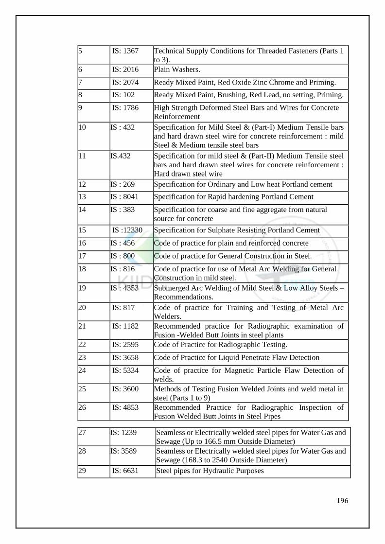
196
5 IS: 1367 Technical Supply Conditions for Threaded Fasteners (Parts 1
to 3).
6 IS: 2016 Plain Washers.
7 IS: 2074 Ready Mixed Paint, Red Oxide Zinc Chrome and Priming.
8 IS: 102 Ready Mixed Paint, Brushing, Red Lead, no setting, Priming.
9 IS: 1786 High Strength Deformed Steel Bars and Wires for Concrete
Reinforcement
10 IS : 432 Specification for Mild Steel & (Part-I) Medium Tensile bars
and hard drawn steel wire for concrete reinforcement : mild
Steel & Medium tensile steel bars
11 IS.432 Specification for mild steel & (Part-II) Medium Tensile steel
bars and hard drawn steel wires for concrete reinforcement :
Hard drawn steel wire
12 IS : 269 Specification for Ordinary and Low heat Portland cement
13 IS : 8041 Specification for Rapid hardening Portland Cement
14 IS : 383 Specification for coarse and fine aggregate from natural
source for concrete
15 IS :12330 Specification for Sulphate Resisting Portland Cement
16 IS : 456 Code of practice for plain and reinforced concrete
17 IS : 800 Code of practice for General Construction in Steel.
18 IS : 816 Code of practice for use of Metal Arc Welding for General
Construction in mild steel.
19 IS : 4353 Submerged Arc Welding of Mild Steel & Low Alloy Steels –
Recommendations.
20 IS: 817 Code of practice for Training and Testing of Metal Arc
Welders.
21 IS: 1182 Recommended practice for Radiographic examination of
Fusion -Welded Butt Joints in steel plants
22 IS: 2595 Code of Practice for Radiographic Testing.
23 IS: 3658 Code of Practice for Liquid Penetrate Flaw Detection
24 IS: 5334 Code of practice for Magnetic Particle Flaw Detection of
welds.
25 IS: 3600 Methods of Testing Fusion Welded Joints and weld metal in
steel (Parts 1 to 9)
26 IS: 4853 Recommended Practice for Radiographic Inspection of
Fusion Welded Butt Joints in Steel Pipes
27 IS: 1239 Seamless or Electrically welded steel pipes for Water Gas and
Sewage (Up to 166.5 mm Outside Diameter)
28 IS: 3589 Seamless or Electrically welded steel pipes for Water Gas and
Sewage (168.3 to 2540 Outside Diameter)
29 IS: 6631 Steel pipes for Hydraulic Purposes

197
30 IS: 7343 Code of practice for ultrasonic Testing of Ferrous Welded
Pipes and Tubular Products
31 IS: 2598 Safety Code for Industrial Radiographic Practice
32 IS: 5822 Code of Practice for Laying of Electrically Welded steel pipes
for water supply
33 IS: 1608 Mechanical testing of Metals.
34 IS: 9595 Metal Arc welding of Carbon and Carbon-Manganese Steels.
35 IS: 2825 Code of unfired Pressure Vessels
36 IS: 5504 Code for Spiral Welded PIPES(457mm to 3250mm Outside
Diameter)
37 IS: 10748 Requirements for Weld able Hot Rolled Carbon Steel Strip in
Coils.
38 IS: 10234 Recommendation for radiography for general pipeline
welding.
39 API-1104 Welding of pipeline & related facilities
40 ASTME 94 Guide for Radiographic Testing
41 ASTME709 Guides for Magnetic Particle Examination.
42 ASTM E
165
Test Method for Liquid Penetrate Examination.
43 AWS:A-5.1 Specification for Mild Steel Covered Arc Welding
Electrodes.
44 AWS: A-
5.17
Specification for Bare Mild Steel Electrodes and Fluxes for
Submerged Arc Welding
45 BS EN 499 Welding Consumables. Covered Electrodes for Manual Metal
Arc Welding of Non Alloy and Fine Grain Steel.
Classification
MATERIALS
Steel Coils - The steel Coils for pipes, fittings, specials and stiffeners shall be of mild
steel conforming to IS: 10748 grade III and shall bear ISI mark
Welding Consumables - such as electrodes, filler rods and wires shall conform to IS: 814,
IS: 3613, IS: 6419 and IS: 7280 and shall be of KIIDC approved make (If any).
Before fabrication of pipes and specials/fittings is commenced, the copies of the mill
sheets and the MANUFACTURER's test certificates for Coils and other materials
required for the fabrication shall be submitted by the Contractor to the Engineer for his
approval.
When requested by the Engineer, the Contractor shall supply free of charge to the
Employer, for testing suitable samples of the materials to be used/used in the Works. The
cost of such tests shall be borne by the Contractor and shall be included in his item rates.
INSPECTION
All works and material under specification will be rigidly inspected during all phases of
manufacture and testing and such inspection shall not relieve the Contractor of his
responsibility to furnish materials and performed work in accordance with this
specification. The Contractor shall notify the Engineer, in advance of the production of
materials and fabrication thereof, in order that the Employer may arrange for mill and
198
shop inspection.
The Engineer may reject any or all materials or works that do not meet with any of the
requirements of this specification. The Contractor shall rectify or replace such rejected
material/performed work at his own cost, to the satisfaction of the Engineer.
The Engineer shall have free access to those parts of all plants or any other premises and
sites that are concerned with the furnishing of materials or the performance of work under
this specification.
The Contractor shall furnish to the Employer's inspector reasonable facilities and space
without charge for inspection, testing and obtaining of any information he desires in
respect of the character of material used and the progress and manner of the work.
The Contractor shall supply free of cost required specimen of materials for testing by the
Owner at any time during the progress of work and shall bear the cost of all such tests or
retests to the satisfaction of Engineer.
The Contractor shall provide 2 (two) sets of accurate `Go' and `No Go' ring gauges to
measure the diameter of pipes specials and fitting for the use of the Engineer at no extra
cost.
FABRICATION OFPIPE
1.4.5.1 General
All Pipes (ISI Marked) and specials shall be manufactured as per IS: 1239 part 1/ IS: 3589
and IS: 5504 out of new mild steel HR Coils (IS: 10748 grade-III) which shall be free
from any cracks, surface flaws, laminations, excessive fittings or any other defects. The
pipes shall be truly cylindrical, and straight in axis. The ends shall be accurately cut and
prepared for field welding. The external circumference of the pipe pieces which are to be
fixed adjacent to flange adapter with fixed outer diameter shall not deviate from
theoretical one by more than 1 mm. To obtain this accuracy the pipe shall be rolled several
times, if necessary, as pipe pieces should be truly cylindrical. The external longitudinal
welding of this pipe shall be ground smooth flush with surface to the satisfaction of the
Engineer, for a length of 200 mm. No extra cost shall be charged by the Contractor for
this grinding work. However, the pipe shall be manufactured as per tender specification.
Minor repair by welding or otherwise shall be permitted at the discretion of the Engineer,
but such repairs shall be done only after obtaining the previous permission of the
Engineer. Any pipe or part thereof which develops injurious defects during shop welding
or other operations shall be rejected.
1.4.5.2 Permissible Stress
The permissible stress in the pipe shell shall be related to yield stress (fy) of pipe material
making due allowance for weld efficiency of the joint.
Working stress for combined bending and direct tensile stress shall not exceed 60% of
yield stress ofthe material making due allowance for efficiency of welded joint (as per
IWWA M- 1).
Working stress for combined bending and direct compressive stress shall notexceed 50%
of yield stress making due allowance for weld efficiency.
It is also necessary to check the shell thickness for adequate factor of safety against failure
by buckling. For field welded joint, efficiency factor of 80% is generally adopted, while for shop
welding joint 90% efficiency is allowed (as per IS 5822).
1.4.6 FABRICATION
The Contractor shall get the fabrication work done in a duly valid licensed factory of his
own or that of an approved nominated sub-contractor. This factory meant for fabrication
of pipes, specials etc. shall also be involved with testing etc., machining as well as
199
painting. For completing the work under the present contract within the contract period,
the factory shall be equipped with adequate number of various equipment and plant such
as:
Plate bending machines for rolling of pipe drums
Automatic welding machines (suitable for circumferential welding)
Hydraulic Testing Machines
Travelling gantry or crane of capacity 10 Tones or above.
Mobile cranes for loading/unloading of Coils, pipes etc. 15 tones capacity each
Lathe for machining of the flanges, rings, Coils etc.
Equipment for sand blasting and applying paint by spray gun.
Equipment for cold pressing of Coils up to 25 mm thick to the required curvature
(specials, plug Coils etc.)
Bending machine of adequate capacity for manufacturing ring girders and other
necessary equipment.
The factory shall have adequate area, and shall also have stacking yard for the stacking
of Coils, structural, fabricated pipes etc. and the scrap.
The Bidder may establish pipe fabrication factory within the project site for minimizing
the transportation of pipes after fabrication to bring the pipes to the trench where pipes
are to be laid. Contractor shall furnish with his bid the details of the factory where he
intends to get the fabrication done, such as its location within the project site and the
equipment, plant and other facilities available in the factory for the manufacture of M.S.
Pipes and special required under this contract. This shall be as per the MOU executed
with the pipe MANUFACTURER.
CUTTING OF COILS OR FROM COIL ROLLED AS PER REQUIRED SIZES
The Coils shall be indented in such length as to have minimum wastage and so as to make
the pipe as far as possible.
Before cutting, all the edges of the Coils shall be cleaned by brushing/grinding on both
the sides. After the Coils are cut, the edges shall be made smooth and even by polishing
with an electrical or pneumatic grinder toremove all inequalities. Care shall be taken to
see that the cut edges of the plate are perfectly straight. Jigs to be used for this purpose
shall depend upon the types of cutting machine used. The Coils cut to the required shape
shall be checked for correctness before they are rolled into pipe drums. If any corrections
are required, the Contractor shall do the same by re-cutting, if necessary.
ROLLING OF COILS
The Coils prepared as mentioned above are cut to the exact size shall be put into a rolling
machine to form a pipe of the required diameter as under:
The Contractor shall adjust the rolling machine so as to give a uniform curvature to the
pipe throughout its circumference.
The curvature obtained shall be checked by the Contractor's foreman during the process
of rolling and if proper curvature is not obtained at any place including the ends, the
rolling operation shall be repeated at this stage
Heating of Coils to obtain the desired curvature shall not be permitted.
WELDING
All components of a standard shell, either straight or bent etc. shall be welded, wherever
possible by use of automatic arc welding machine by Submerged Arc Welding Process
with alternating current. Generally, hand welding shall not be permitted except specific
cases, where it is absolutely necessary. This should be done in consent with client’s
representative. Hand welding shall also not be permitted except for sealing runs and such
other minor works at the discretion of the Engineer-in-charge. The strength of the joint
shall be at least equal to that of the parent material.
200
The Contractor shall use electrodes of approved make and size, the size depending on the
thickness of coil and the type of joint. It shall also be used with standard current and arc
voltage required for the machine in use with such modifications as may be found
necessary after experimental welding. For this purpose, samples of welded joints shall be
prepared and tested in the presence of the Engineer. The values once determined
shallbemaintainedthroughoutthework and if any modifications are to be made, a written
permission of the Engineer shall be obtained. In the case of thin sheets, electric arc
welding may not give satisfactory results and gas welding shall be resorted to. Gas
welding shall be subject tothesame specifications and tests as thoseforelectric welds.
Welding should be carried out inside as well as outside.
All the shop and field joints shall be welded, all welding shall conform to the requirements
of IS 9595 and IS 4353.
All circumferential joints shall be double welded butt joints. Field joints shall be from
outside, with a sealing weld from inside. End preparation for such welding shall conform
to IS: 2825.
All circumferential welds involving Coils of unequal thickness shall be so kept that the
inside surfaces of Coils match to provide stream lined joints without alteration in the
internal diameter. As far as practicable, welding of dissimilar thickness of shells shall be
carried out in the shops.
The welding shall be of the best workmanship free from flaws, burns, etc. and the
Contractor shall provide for his own electrodes and equipment, ovens to keep the
electrodes at the desired temperatures and dry. In order to maintain a good standard in
welding, welders shall be tested by the Contractor with prior intimation to the client
before they are entrusted with the job. Qualification standard for welding procedures,
welders and welding operation shall conform to the requirements of IS: 7307 and IS: 7310
(latest). Periodical tests as regards their efficiency shall also be taken at intervals of about
6 months and those found inefficient shall be removed from the job. Only those who pass
the test shall be posted on the job. If an incompetent welder has already welded some
pipes, all welding done by him previously shall be fully checked by X- ray in addition to
the regular X-ray inspections. The defects if any shall be set right to the satisfaction of
the Engineer. All such check tests and rectification of defects shall be entirely at the cost
of the Contractor. No pipes or steel sections shall be erected unless the work of the welder
concerned has been proved to be satisfactory. Specially selected welders shall do site
welds.
A record shall be maintained showing the names of welders and operators who have
worked on each individual joint. Hand-welding shall preferably be carried out by a pair
of welders (parallel welding putting two welders at a time both will be working in
diametrically opposite side of the curvature. Welding shall be divided into 4 quadrants
shall be welded simultaneously, so that by observing proper sequence, distortion can be
avoided. A joint entrusted to a particular individual or a pair shall be as far as possible,
completed by them in all respects, including sealing run. No helper or other unauthorized
person shall be permitted to do any welding whatsoever. In case of infringement of above,
the persons shall be punished as directed by the Engineer.
The welded joint after welding should not become brittle or sensitive to blows and there
should be no loss of toughness due to welding or heat treatment. The material after
welding and heat treatment is to be tougher than the base metal and is to retain its original
ductility. No allowance will be made for thinning of weld and the weld should in no point
be less than the nominal thickness of plate.
Upon receipt of the order and prior to the start of fabrication, the Contractor shall submit
to the Engineer for his approval the ``welding procedure'' he intends to use in the shop
201
work. Similarly, prior to the start of the field welding, procedure for the field welding
must be submitted to the Engineer for his approval. Manual welding shall be adopted
only when machine welding is not possible.
ULTRASONIC & RADIOGRAPHIC TEST OF WELDEDJOINTS
1.4.10.1 Manufactured in Site Factory/Workshop
For the mild steel pipes manufactured in site factory/workshop, fabricated from mild steel
Coils, 100 % of weld length of each pipe shall be subjected to Ultrasonic Test either on-
line or off-line. For the mild steel pipes manufactured in site Factory/Workshop
fabricated from mild steel coils, 15% of weld length of each pipe shall be subjected to
Radiography Test by Digital Image/ X-Ray Film Method. (IS: 10234)
FIELD WELDED JOINTS
For Field welded joints, 100% of each welded joint shall be examined by Ultrasonic Test
either online or offline and 15% weld length of each welded joint shall be examined by
Radiography Test.
In case of failure of any of the joint during RT, the contractor is to carry out radiography
of thrice the number of field joints which includes 1 Repair and 2 Penalty shots.
Subsequent to RT of thrice the number of field joints, if anyone of the joint fails the
Contractor has to carry out RT of all field welded joints i.e. 100 % basis. All these testings
shall be carried out by the contractor at his own risk and cost.
The weld ripples or weld surface irregularities, on both inside and outside shall be
removed by any suitable mechanical process to a degree such that resulting radiographic
contact due to any remaining irregularities cannot mark or be confused with that of
objectionable defect. The radiograph shall be made in strict accordance with the latest
requirements and as per the latest and most efficient technique either with X-ray or
gamma ray equipment.
The photographs are to be marked in such a way that the corresponding portion of the
welded seam can be readily identified. All radiographs will be reviewed by the Engineer
to identify the defect and determine those which must be removed. Defects that are not
acceptable shall be removed by chipping, machiningorflame gouging to sound metal and
the resulting cavities shall be welded. After rectification, the joint is to be radio graphed
again to prove the quality of the repair. The Engineer based on the latest standards
prescribed by Indian Standard specification will judge the radiographs as acceptable or
unacceptable.
All X-ray shall be made with equipment and by personnel furnished by the Contractor.
Films shall be developed within 24 hours of exposure and be readily accessible at all
times for inspection by the Engineer. The Contractor shall provide for the use of the
Engineer suitable X- ray viewing equipment. X-ray films shall be properly maintained by
the Contractor and shall be handed over to the department on completion of the Contract.
All films shall be identified by the No. and chart prepared indicating location of the joint
each X-ray photo represents. In the event of additional radiographic inspections required
of any work associated with the pipe erection, the Radiographer at the discretion of the
Engineer shall perform such inspection.
RADIOGRAPHIC INSPECTION
1.4.12.1 General
The Engineer shall assure himself that the welding procedure employed in the
construction of pipes has been qualified. The Contractor shall submit evidence to the
Engineer that the requirements have been met. The Contractor shall certify that the
welding of pipes has been done only by qualified welders and welding operators and the
Engineer shall ensure himself that only qualified welders and welding operators have
202
been used.
The Contractor shall make available to the Engineer a certified copy of the records of the
qualification tests of each welder and welding operator. The Engineer shall have the right
at anytimeto call for and witness tests of welding procedure or of the ability of any welder
and welding operator.
Radiographic Inspection of welded joints
All welded joints to be radio graphed shall be examined in accordance with codes as
specified below:
Sl. No. Code
Number
Description
1 IS : 2595 Code of Practice for Radiographic Testing
2 IS : 4853 Recommended Practice for Radiographic Inspection of
Fusion Welded Butt joints in Steel Pipes.
3 IS :1182 Recommended Practice for Radiographic Examination of
Fusion Welded Butt-Joints in steel Coils.
The reinforcement on each side of all butt welded joints shall not exceed 1.5 mm. A
complete set of radiographs and records as described in IS: 2595 for each job shall be
retained by the Contractor and kept on file for a period of at least five years.
Radiographers performing radiograph shall be qualified in accordance with SNT-TC-1A.
Supplements and Appendices ``Recommended Practice for Non-destructive Testing
Personnel Qualification and Certification'' published by the American Society for Non-
destructive Testing as applicable for the technique and methods used.
Final acceptance of radiographs shall be based on the ability to see the prescribed
pentameter image and the specified hole.
The acceptance criteria for radiography of the joint shall be as per IS-10234
1.4.13 THERMAL STRESS RELEIVING
Not applicable
TOLERANCE
The shell in the completed work shall be substantially round. The difference between
maximum and minimum inside diameters at any cross section shall not exceed 1% of the
nominal diameter of the cross section under consideration subject to a maximum of 10
mm.
Machined parts shall be within the limits specified by IS 3589.
Straight pipes shall have their faces perpendicular to the axis of the section with a
maximum deviation of 2 mm on either side of the plane. Pipe ends shall be beveled as per
IS: 3589. The pipes shall be supplied in length of 10.5 m to 12.5 m.
For the shell thickness, no negative tolerances are acceptable.
SHOP TESTING
After fabrication, but before application of protective coatings all pipes and specials shall
be subjected to a shop hydraulic test (100%). Standard lengths ofpipes shall be directly
subjected to test and non-standard pipe and elbows can be tested as standard pipe before
being cut to size.
1.4.16 FIELD HYDRAULIC TESTING
The Pipeline after lying at site shall be subjected to 100% Hydro testing. The test pressure
shall be 1.5 times working pressure or 6 kg/cm2 whichever is higher. The pressure shall
be maintained for a period of 24 hours. The length of pipe for hydro testing shall be
generally 5 km as directed by Engineer-In-Charge.
203
Each pipe shall be filled with water and the pressure slowly and uniformly increased until
the required test pressure is reached.
The pipe to be tested shall be given a serial no. which shall be painted on its inside
together with details such as pipe No. Shell thickness, diameter, length etc. as directed. It
shall be entered in the register to be maintained by the Contractor.
Prior to testing, the pipe shall be inspected thoroughly and all the apparent defects in
welding such as jumps, porosity etc. shall be repaired by gouge and re-welding.
The hydraulic test shall be carried out under cover at the fabrication shop, in the presence
of and to the satisfaction of the Engineer or the inspection agency appointed by the
Employer.
For indicating the pressure inside the pipe an accurate pressure gauge of approved make
duly tested and calibrated for the accuracy of readings shall be mounted on one of the
closures which close the pipe ends.
The pressures shall be applied gradually by approved means and shall be maintained for
a period of 24 hours. The pipe shall be hammered throughout its length with sharp blows,
by means of a 1 kg. hand hammer.
The pipe shall withstand the test without showing any sign of weakness, leakage, oozing
or sweating. If any leak or sweating is observed in the welded joints, the same shall be
repaired by gouging and re-welding after dewatering the pipe. The repaired pipe shall be
re-tested to conform to the specified pressure.
If any leak or sweating is observed in pipe shell the pipe under test shall be rejected
temporarily. The Contractor shall stack such rejected pipesseparately in his yard.
TheEngineershall inspect the same and after taking cuts if necessary, shall determine the
nature of repairs to be carried out thereon and shall then decide as to how and where they
shall be used. No payment shall be made for handling or carrying out repairs, but,
payment for the fabrication and hydraulic testing of the pipe shall be released only after
acceptance of the pipe with necessary repairs and subsequent testing etc. are carried out
by the Contractor to the satisfaction of the Engineer. The Engineer shall be supplied with
two copies of the results of all the tests carried out.
The Mechanical Tests for Pipe material at Manufacturers work shall be carried as per
approved Quality Assurance Plan(QAP) and tests shall be as per IS:1239/
IS:3589/IS:5504.
1.4.16.1 Testing of Site Welded Joints
The welded joints at site shall be tested for Tensile test, Bend test &Tre-panned plug in
accordance with procedure laid down in as per the latest edition of IS No. 3600 “code of
procedure for testing of fusion welded joints and weld metals in steel”.
Test pieces shall be taken by the contractors from the welded joints at the position on
fabricated pipes pointed out by the Engineer in-charge.
The sample so taken shall then be cut to the exact shape and dimensions and machined as
described below and handed over to the Engineer-in-charge for testing. All the work up
to and including machining and arranging for test shall be done by the contractors.
SUBMISSION OF DAILY PROGRESS REPORT
The Contractor shall submit to the Engineer a daily progress report in the proforma
approved by the Engineer, wherein all the details of the work carried out in the factory
shall be fully recorded. Similarly, works done in the various units in the factory shall be
separately mentioned. The Contractor shall maintain a register of all the finished materials
giving dates of carrying out important operations such as testing, transport, etc. The
registershallbepresentedat least once a week to the Engineer who shall initial the entries
after verification.
204
TRANSPORTING OF PIPES, SPECIALS etc.
All pipes and specials fabricated in the site factory / workshop and temporarily stacked
in the Contractor's yard shall be transported to the site of laying after cleaning them
internally, etc. The loading in the factory shall be carried out by means of either a crane,
gantry or shear legs, so as not to cause any damage to the finished material. Similarly,
while unloading and stacking, great care shall be taken to ensure that the material is not
damaged or dented. The contrivances to be used for unloading will be different in
different situations and in each case the one approved by the Engineer shall be adopted.
The material stacked at site shall be jointly inspected by the Engineer and the Contractor
and defect or damage noticed shall be repaired to the satisfaction of the Engineer before
payment is admitted.
Props of approved designs for maintaining circularity having M.S. Angle/Pipe at both
ends to avoid metal to metal contact shall be fixed to the pipes during transit to avoid
undue sagging and consequent distortion. After the pipes are carefully stacked, props
should be retained till pipes are joined in trenches and then props are re-used for
subsequent similar operations. The stacking ground, both in the Contractor's yard and at
the site of laying shallbeselected in such a way as not to get waterlogged during monsoon.
If this cannot be done, the pipes shall be supported on sleepers to avoid contact with wet
earth and subsequent rusting. In order to prevent sagging during transit, savings of steel
Coils can be utilized by cutting to the required length and tacking the same to the pipe
ends, in placeofprops, if approved by the Engineer.
As explained in earlier paragraphs, materials such as pipes, tapers, etc. may be transported
to the site of laying as soon as the material is finished in all respects with the permission
of the Engineer to avoid congestion in the Contractor's yard. However, materials such as
expansion joints, composite bends, `T' branches and other complicated materials shall be
stacked in the Contractor's yard until they are required for laying in the field. In view of
this, the work of fabrication of such materials shall be properly synchronized as far as
possible with the laying operations.
Fabricated materials such as specials, appurtenances, bolts, nuts, distance pipes, flanges,
saddles, collars bypass arrangements etc. shall be transported to the site of laying from
the fabrication shop according to the needs of the laying operations only. In regards access
roads, the Contractor shall note that access road may lead up to some points on the
alignment the Contractor shall have to make his own arrangement for connecting
approaches to transport the pipes cross country to the actual site of laying at his own cost.
Whatever may be the mode of transport he uses it shall be incumbent on the Contractor
to carry and stack the pipes and specials along the alignment as close as possible to the
site of laying.
PROCEDURE FOR RECEIVING STEEL PIPES
1.4.19.1 General
To ensure that the work of erecting pipes is not held up at any stage and place, the Contract
or shall maintain an adequate stock of standard specials, flange rings, plug Coils, manhole
covers, etc. and short length of smaller diameter pipelines, etc. at site in his field stores,
in consultation with the Engineer. Wherever possible, the Contractor shall arrange one
full month's requirement of pipes, specials, etc. stacked along the alignment.
1.4.19.2 Stacking of Pipes, etc. and Inspection
The Contractor shall keep in each section a responsible representative to take delivery of
the pipes, specials and appurtenances, etc. transported from the fabricating stockyard or
received from any other work site to the site of laying and to stack along the route on
timber skids. Padding shall be provided between coated pipes and timber skids to avoid
damage to the coating. Suitable gaps in the pipes stacked shall be left at intervals to
205
permit access from one side to the other. The pipes, specials, appurtenances so received
on site shall be jointly inspected and defects recorded, if any, such as protrusions,
grooves, dents, notches, damage to the internal coating etc. shall be pointed out
immediately to the Engineer at the site and in the acknowledgement challans. Such
defects shall be rectified or repaired to the satisfaction of the Engineer entirely at the
Contractor's risk and cost.
1.4.19.3 Handling ofPipes, Special Appurtenances etc.
It is essential to avoid damage to the pipes, fittings and specials, etc. or their coatings at
all stages during handling. The pipes and specials shall be handled in such a manner as
not to distort their circularity or cause any damage to their surface treatment. Pipes shall
not be thrown down from the trucks nor shall they be dragged or rolled along hard
surfaces. Slings of canvas or equally non-abrasive materials of suitable width of special
attachment shaped to fit the pipe ends shall be used to lift and lower coated pipes to
prevent damage to the coating.
Great care shall be taken in handling the pipe right from the first operation of manufacture
until they are laid and jointed. The Contractor will provide temporary props as described
earlier in order to prevent any sagging of the pipes while they are stacked in their yard
and while transporting to the site of delivery, i.e. laying. The props shall be retained until
the pipes are laid and welded. If at any time these props are found to be dislodged or
disturbed, the Contractor shall immediately reinstate them in such a way that the true
shape of the pipe shell or specials is maintained to the satisfaction of the Engineer. No
defective or damaged pipe or special shall be allowed to be used in the work without
rectification to the satisfaction of the Engineer. Any damage to the coating shall be
repaired by the Contractor at his own cost to the satisfaction of the Engineer.
1.4.19.4 Dents
Whenever any dent, i.e. a significant alteration of the curvature of the pipe shell is noticed,
the depth of the dent shall be measured between the lowest point of the dent and the pipe
shell curvature line. All dents exceeding 2 percent of the outer diameter of the pipe shall
be removed by cutting out a cylindrical portion of the pipe and replacing the same by an
undamaged piece of the pipe. The Engineer may permit insert patching if the diameter of
the patch is less than 25 percent of the nominal diameter of the pipe. Repairs by
hammering with or without heating shall not be permitted. Any damage to the coating
shall also be carefully examined and rectified.
1.4.19.5 Marking
The component parts of the pipes shall be carefully marked for identification in the field.
The marking shall be on the side which will be the inside of the pipe after bending.
The marking operation shall be conducted with full size rulers. Only blunt nose punches
should be used.
The Coils used for fabrication of pipes shall be laid out in such a way that when the shells
are completed one set of original identification markings for the material will be plainly
visible. In case these markings are unavoidably cut out, they shall be accurately
transferred by the Contractor to a location where these markings will be visible on the
completed work.
After the hydraulic tests on the specials and other items, the number of the shell in the
line as it will be erected and the direction of flow shall be stamped in a prominent manner
on each piece.
A register shall be maintained in suitable Performa giving the following information for
each shell tested:
Serial No.
Shell No.
206
Date of test
Thickness and specification of steel Weight of shell tested
Maximum test pressure
Details of test performance Details of radiographic examination of welds
Name of Engineer's representative witnessing tests
A copy of these details shall be furnished to the owner free of cost.
No separate payment will be made for these markings and the rates for the items
concerned shall be deemed to include the cost of such markings.
LAYING OF PIPELINE
1.4.20.1 General
Unless specified otherwise, the pipeline shall be buried with minimum cover at top, as
shown on drawings. No material shall be erected unless it has been previously passed by
the Engineer. Pipe shall be protected from outside with rock shield mesh/soft
murrum/Sand wherever required/as directed by Engineer-In-Charge. In such cases, the
depth of soft murrum/sand shall be 300mm above top of pipe. The mesh shall be
manufactured from HDPE material with weight per metre not less than 750 grams. The
size of mesh shall be as per requirement of Engineer-in- Charge. The mesh shall be of
such strength to protect the external coating from impact of rock during back filling. The
height of falling of rock shall range from 3 to 5 m over top of pipe. The mesh shall be
spirally wrapped over pipe with suitable overlap and properly tied with non - metallic
ties. The mesh shall be spirally wrapped over pipe with suitable overlap. After field joints
and at all specials also shall be wrapped by rock shield protection mesh
Erection of fabricated shells shall be carried out by the Contractor who shall equip
himself, at his cost, with all necessary tools, machinery, labour, etc. required for the
purpose.
1.4.20.2 Welding
Except for routine welding of joints, no other work shall be done in the absence of
Contractor's engineer, either during the day time or at night. Chipping shall not be kept
in arrears for more than 15 joints.
1.4.20.3 Temperature
The components of the pipeline such as base Coils, top Coils and pedestals have been so
designed that the centres of the Coils and pedestals shall coincide at the Mean
Temperature (30°).
For this reason, all works such as fixing flanges, base plate etc. in true alignment and in
correct position and tack welding pipes shall be done at the mean temperature.
For ascertaining the temperature, the Contractor shall provide mercury cups and fix them
to the pipe shell from outside and shall also provide thermometers of the required type
and range. No extra payment shall be made for this.
1.4.20.4 Saddle supports
Unless, otherwise, specified, pipeline shall be underground. However at unavoidable
reaches it shall be on R.C.C. saddles spaced at about 6 m centre to centre. The material
and construction of R.C.C./Steel structures such as saddles, anchor blocks, crossings etc.
associated with the work of pipe line shall conform to the relevant IS codes, good
engineering practice and as directed by the Engineer. The pipes to be laid on saddle
supports shall be erected at mean temperature. Saddle supports shall either be sliding type
or fixed type. For both the types of supports a 10mm thick double plate shall be welded
to the part circumference of the pipeline that will make contact with the saddle and
another similar plate shall also be embedded in the concrete saddle with necessary
arrangement to facilitate welding it to the double plate welded to the pipe, in case of fixed
support. In case of sliding support, the pipe shall be allowed to slide freely over the plate
207
embedded in the saddle. Alternatively to achieve fixity, the pipe shall be anchored by
providing suitable anchor block. The rate for laying the pipe on saddle support shall
include for laying, aligning, tack welding, provision of rigging screws with screw eyes
etc., complete.
In addition to above, the pipe shall be held in position on saddles with two numbers 50mm
x 8mm thick holding down traps fixed to the saddles with holding down bolts and nuts.
1.4.20.5 Erection ofShells
The erection shall be true to position, lines and grade of the trench prepared or as modified
by the Engineer. The Contractor shall provide at his cost necessary saddles, pads, spider
etc., all necessary instruments and other materials and labour required for proper erection
of shells in position and for the Engineer in checking the correctness of the erection.
Alignment of sections at edges to be butt welded shall be such that the maximum offset
is not greater than the values given below:
Thickness
‘t’ (mm)
Offset in Longitudinal
joints (mm)
Offset in Girth joints
(mm)
Up to 12 0.25 t 0.25 t
12 to 20 3 mm 0.25 t
20 to 40 3 mm 5 mm
40 to 50 3 mm 1/8 t
Over 50 Lesser of 0.0625 t or 10mm Lesser of 0.125 t or 20mm
The best of welders as selected from their work in the Contractor's workshop shall be
selected for in-situ welding of the shells. The relevant provision under welding such as
qualification standard for welding procedures, tests on welder's work and removal of
defects etc., shall also apply to in-situ welding.
General Sequence of Operations
Before commencing the work of pipe laying, the Contractor shall study the L -section of
the pipeline for the section concerned. He shall also study the details of laying i.e.
underground or aboveground. The underground pipeline shall be laid on sand cushioning/
bedding as shown on the drawing. The difference in depth due to uneven excavations
shall be made up by sand cushioning.
Pipe laying shall generally start from the fixity points on either side, the expansion joints
if required for pipeline aboveground being provided last. Fixing points are at all anchor
blocks. Where such blocks are not required for long lengths, fixity shall be achieved by
fixing the pipeline to the special type of R.C.C. or steel saddles as specified. The distance
between successive fixity points shall not exceed 300 m.
Thrust and Anchor blocks shall be constructed before commencing the pipe laying work
in any section. The construction of the blocks shall be carried out in 3 stages: in the first
stage the lower part up to 150 mm below the invert of the pipeline including concrete
chairs to support it shall be constructed; in the second stage the pipeline on this part of
the block shall be laid; and lastly, the remaining block around and over the pipeline shall
be constructed.
The fixity saddles and ordinary saddles if the pipeline is aboveground shall be cast-at least
3 weeks before the pipeline is laid on them. After all saddles between successive fixity
points have been cast, a line plan showing the actual position thereof shall be prepared,
after taking levels and measuring distances. In case of any errors in casting the pedestals,
corrections shall be applied. The pipe laying work shall then start from the fixity points
and shall proceed towards the expansion joints. The method of jointing the pipes and
erecting them on previously cast
208
R.C.C. saddles shall be determined by the Contractor depending upon the type of plant
equipment and personnel available with them.
The pipe strakes shall be assembled in position on the saddles either by the cranes,
portable gantries, shear legs or any other equipment approved by the Engineer. Normally,
not more than two pipes shall be aligned, tacked and kept in position on temporary
supports. The Contractor shall not proceed with further work, until the circumferential
joints of these pipes are fully welded. During assembly, the pipeline shall be supported
on wooden sleepers and wedges, with the free end of the pipeline held in position by
slings to avoid deflection due to temperature variations during the day. In general, the
assembly of pipe strakes and one run of welding shall be done during the day time while
full welding including the external gouging and sealing runs shall be done after 5 p.m. or
so. The Contractor shall maintain the continuity of the work by adding two more pipes
on the second day in a similar manner, after full welding of the previous joints is
completed during the night. While this new work is being done, the Contractor shall
proceed with the work of providing permanent supports for the pipeline assembled and
welded previously.
Fixing Expansion Joint
The work of laying pipeline at above the ground, laying starts from the fixed points and
proceeds towards the expansion joints. It shall be continued until the gap between the
pipe ends is less than the lengths of the expansion joint plus pipe strake length. At this
stage, the exact gap between the pipe ends shall be measured at mean temperature of that
locality. Let it be `X'. Similarly, the exact length of the pipe strake and the expansion
joint bought at site shall be measured at the same temperature let these be `Y' and `Z'
respectively. Normally, the length of the expansion joint (`Z') is standard.
1.4.22.1 Case when`Y' plus `Z' is more than `X' or equal to `X' (i.e. fixing of expansion
joint without strip)
At mean temperature the exact gap between pipes shall be measured. Free ends of pipes
shall be brought in a correct line and level; lateral movement, if any, shall be corrected.
Then the gap between the free ends shall be made equal to the exact length of the
expansion joint by cutting one of the pipe ends. Choice of the end to be cut must be made
from the point of view of bringing the expansion joint to a central position.
The expansion joints are normally supplied without packing. The normal length of the
expansion joint shall be reduced by about 100 mm by cutting the inside locks and
inserting the inner strake by means of turn buckles. At mean temperature this expansion
joint shall be inserted inside the gap (care being taken to keep the tapered portion on the
down-stream side), and both ends shall be tack welded to the pipe ends, after pulling the
expansion joint. (Tacks of these two joints shall be of longer length, approximately 100
mm long).
Welding of these two joints of the expansion joints shall be started only after it is
ascertained by taking observations that the expansion joint is functioning properly. The
procedure to be followed for taking observations as specified.
1.4.22.2 Casewhen ̀ Y' plus ̀ Z' is less than ̀ X' (i.e. fixing of expansion joints with strap)
The expansion joint shall be laid in locked position. Before laying the pipes adjacent to
the expansion joint, the exact gap between the pipes shall be calculated by taking
measurements of the first pipe (upstream of the expansion joint), and the second pipe
(downstream of the expansion joint) at Mean Temperature.
If the gap is less than 100 mm, the second pipe shall be cut to make the desired gap of at
least 100 mm. If the gap is more than 200 mm, suitable distance piece of not less than
600 mm shall be inserted after cutting necessary length of the first pipe.
The second pipe shall then be laid in position. Then a strap of length equal to three times
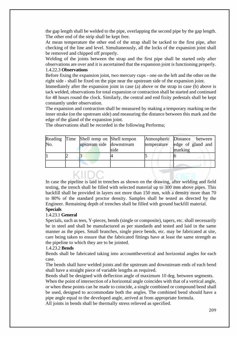
209
the gap length shall be welded to the pipe, overlapping the second pipe by the gap length.
The other end of the strip shall be kept free.
At mean temperature the other end of the strap shall be tacked to the first pipe, after
checking of the line and level. Simultaneously, all the locks of the expansion joint shall
be removed and chipped off properly.
Welding of the joints between the strap and the first pipe shall be started only after
observations are over and it is ascertained that the expansion joint is functioning properly.
1.4.22.3 Observations
Before fixing the expansion joint, two mercury cups - one on the left and the other on the
right side - shall be fixed on the pipe near the upstream side of the expansion joint.
Immediately after the expansion joint in case (a) above or the strap in case (b) above is
tack welded, observations for total expansion or contraction shall be started and continued
for 48 hours round the clock. Similarly, the central and end fixity pedestals shall be kept
constantly under observation.
The expansion and contraction shall be measured by making a temporary marking on the
inner strake (on the upstream side) and measuring the distance between this mark and the
edge of the gland of the expansion joint.
The observations shall be recorded in the following Performa;
Reading
No.
Time Shell temp on
upstream side
Shell tempon
downstream
side
Atmospheric
temperature
Distance between
edge of gland and
marking
1 2 3 4 5 6
In case the pipeline is laid in trenches as shown on the drawing, after welding and field
testing, the trench shall be filled with selected material up to 300 mm above pipes. This
backfill shall be provided in layers not more than 150 mm, with a density more than 70
to 80% of the standard proctor density. Samples shall be tested as directed by the
Engineer. Remaining depth of trenches shall be filled with ground backfill material.
Specials
1.4.23.1 General
Specials, such as tees, Y-pieces, bends (single or composite), tapers, etc. shall necessarily
be in steel and shall be manufactured as per standards and tested and laid in the same
manner as the pipes. Small branches, single piece bends, etc. may be fabricated at site,
care being taken to ensure that the fabricated fittings have at least the same strength as
the pipeline to which they are to be jointed.
1.4.23.2 Bends
Bends shall be fabricated taking into accountthevertical and horizontal angles for each
case.
The bends shall have welded joints and the upstream and downstream ends of each bend
shall have a straight piece of variable lengths as required.
Bends shall be designed with deflection angle of maximum 10 deg. between segments.
When the point of intersection of a horizontal angle coincides with that of a vertical angle,
or when these points can be made to coincide, a single combined or compound bend shall
be used, designed to accommodate both the angles. The combined bend should have a
pipe angle equal to the developed angle, arrived at from appropriate formula.
All joints in bends shall be thermally stress relieved as specified.
210
Details of thrust collars anchor bolts, holding down straps, saddle Coils should be
furnished together with full specifications in Contractor's fabrication drawing.
1.4.23.3 Manholes
Manholes of 750-mm dia. shall be provided at both the sides of butterfly valves and as
directed by Engineer-In-Charge. Manholes in the pipeline shall be placed in suitable
position in the top quadrant. The Contractor shall fabricate different parts of manhole in
conformity with relevant IS Specification, well-established practices and as directed by
the Engineer.
1.4.23.4 Closing orMakeup sections
Closing or make up sections shall be furnished at appropriate locations on the line to
permit field adjustments in pipeline length to compensate for shrinkage in field welded
joints, differences between actual and theoretical lengths and discrepancies in
measurements.
1.4.23.5 Heads
Test heads may be ellipsoidal, standard dished as per ASME code or hemispherical heads.
They shall be welded in the shop and removed after the test. Allowance should be made
in the length of the pipe section receiving the test head for the welding and removal of
the head and preparation of the plate edges for the final weld after testing.
No separate payment will be made for such test heads. The rate quoted for the hydraulic
test shall be deemed to cover the cost of such installations.
1.4.23.6 Walkways, Stairs, Ladders, Hand Rails etc.
Walkways, stairs, rungs, ladders, hand rails, etc. shall be provided as shown in the
drawings and/or as directed by the Engineer. They shall conform to well established
design and construction for each accessory concerned.
1.4.23.7 Flanges
Flanges shall be provided at the end of pipes or special where sluice valves, blank flanges,
tapers, etc. have to be introduced. The flanges received from the MANUFACTURERs
will have necessary bolt holes drilled. The Contractor shall assemble the flanges in the
exact position by marginal cutting, if necessary, so as to get the desired position of the
sluice valves, etc. either vertical or horizontal and shall then fully weld the flanges from
both sides in such a way that no part of the welding protrudes beyond the face of the
flanges. In case the welding protrudes beyond the flanges and if the Engineer orders that
such protrusions shall be removed, the Contractor shall file or chip them off. If required
and when ordered by the Engineer, the Contractor shall provide and weld gusset
stiffeners, as directed on site. The drilling pattern shall be matching with the drilling
pattern of flanges of valves.
1.4.23.8 Blank Flanges
Blank flanges shall be provided at all ends left unattended for the temporary closure of
work and alsoforcommissioning a section of the pipeline or for testing the pipeline laid.
For temporary closures, non-pressure blank flanges consisting of mild steel Coils, tack
welded at the pipe ends may be used. For pipes subjected to pressures, the blank flanges
or domes suitably designed as per Engineer's requirements shall be provided.
1.4.23.9 Stiffener Rings
The Contractor shall provide stiffener rings wherever required by design. The Contractor
shall weld the same to the pipes with one circumferential run on each side.
All fillet welds shall have a throat thickness of not less than 0.7 times the width of
welding.
Field Hydraulic Test
After erection at site and after the concrete Thrust/anchor blocks have been constructed,
the pipeline shall be subjected toa 100% hydraulic test. The pressure test shall be
211
conducted in as per IS-5822.
During the test, the pipe shall be struck sharp blows with 1 Kg hammer. Water shall not
spout, oozeorsweat either through joints-welded or bolted or the body of the pipe. If any
leakage noticed shall be repaired by the Contractor, which shall include coating and
repairing of the damaged portion. Repairs and replacements and further testing including
the cost of the Coils and other raw materials shall be carried out by the Contractor at his
own cost. If any leakages are observed during the defectsliabilityperiod due to defective
workmanship or material supplied by the Contractor, he shall repair the same to the entire
satisfaction of the Employer, at his own cost.
KIIDC shall assist the contractor in identifying the source & in obtaining permission for
drawl of water for field-testing of pipe. The contractor shall pay for the water and carry
the water to the test location at his cost. The cost of hydraulic testing of the installation
by providing necessary testing equipment, pumping the water, creating and maintaining
pressure, and the necessary bulk heads and their fixtures, and their subsequent removal
and restoring the installation to working trim shall be included in the rate for laying and
testing of the pipe. KIIDC may also provide water for testing and civil construction work
from its adjacent pipeline at a rate of Rs. 4/- per Kiloliter, if feasible. Contractor shall
seek prior permission of department in writing and shall water meter at his own expense.
Progress in Laying
The TENDERER shall submit along with the tender his detailed bar chart for
manufacturing and laying of the pipeline. While preparing his bar chart, the Tenderer
shall plan his activities such that the laying of pipes shall closely follow the manufacturing
schedule and no pipes shall remain stacked in factory or at site for a period more than two
months.
It is mandatory that he shall submit an approach note on how he will carry out this Work
within the contractual period and on the compatible resources in terms of construction
equipment and other facilities that he shall utilize to complete the tendered Work.
Field Destruction Test
Contractor shall perform destruction test of any section of MS Pipeline which Engineer
selects at every 5 KM pipeline laid and shall submit its result to him. The testing shall be
done in the NABL approved laboratory in the presence of representative of the employer.
1.5 PROPERTY CONNECTION
Connection to the building shall be throughan Electro fusion PP saddle and no direct
connection shall be made on the MDPE pipe. This is necessary to prevent leakages and
any contamination in the potable water network.
1.6 PIPE LINE GENERAL
1.6.1 Disinfection of Water Mains
The mains intended for potable water supplies should be disinfected before
commissioning them for use. Special care should be taken to ensure disinfection of new
mains. Among possible sources of contamination are sewer drainage, contaminated soil
in the trench, contamination from workmen or their equipment of both and unavoidable
foreign material present in the trench during construction.
Education of crew members as to the need for avoiding contamination of the main during
construction is fundamental. Contractors and workmen should be thoroughly familiar
with all pertinent state and local requirements governing installation of mains. All sewers,
water mains and other underground conduits should belocated prior to construction,
relocated if necessary, to prevent contamination during construction. Pipe should be
strung on high ground. At all times when construction is not actually in progress,
watertight plugs should be installed in all pipe openings. Gunny sack and rags are not
adequate. Provision should be made to pump any other water that might collect in the
212
trench. Special care should be taken to avoid contamination of valves, fittings, and pipe
interiors, both before and during construction each of them should be inspected and, if
necessary, cleaned before installation.
After pressure testing the main, it should be flushed with clean water at sufficient velocity
to remove all dirt and other foreign materials in the constructed pipeline. When this
process has been completed, disinfection (using, sodium hypochlorite) should proceed by
one of the recommended methods as described in the following-
Continuous Feed
In this method, water from the distribution system or other approved source and the
chlorine is fed at constant rate into the new main at a concentration of at least 20 mg/1. A
properlyadjustedhypochlorite solution injected intothemain with a hypo-chlorinator,
chlorinator and if required, booster pump may be used. The chlorine residual should be
checked at intervals to ensure that the proper level is maintained. Chlorine application
should continue until the entire main is filled. All valves, hydrants, etc., along the main
should be operated to ensure their proper disinfection. The water should remain in the
main for a minimum of 24 hours. Following the 24 hours period no less than 10 mg/1
chlorine residual should remain in the main. The Contractor is requested to provide photo
and take a record of the value of chlorine residual at starting point and after 24 hours before
completion of work. The Employers Engineer shall jointly check the test at sites. If the
value is insufficient, the disinfections work shall be repeated until satisfactory results are
achieved. Waste chlorine residual water must be neutralized before it is discharged to any
drainage, as per approval of Employers Engineer.
Slug Method
In this method a continuous flow of water is fed with a constant dose of chlorine (as in
the previous method) but with rates proportioned to give a chlorine concentration of at
least 300 mg/1. The chlorine is applied continuously for a period of time to provide a
column of chlorinated water that contacts all interior surfaces of the main for a period of
at least 3 hours. As the slug passes tees, crosses, etc., proper valves shall be operated to
ensure their disinfection. This method is used principally for large diameter mains where
continuous feed is impractical. Regardless of the method used, it is necessary to make
certain that backflow of the strong chlorine solution into the supplying line does not occur.
Following the prescribed contact period, the chlorinated water should be flushed to waste
until the remaining water has a chlorine residual approximating that throughout the rest
of the system. Bacteriological tests as prescribed by the authorities should be taken, and
if the results fail to meet minimum standards, the disinfecting procedure should be
repeated and the results again tested before placing the main in service.
If continuous feed method is difficult to apply, Retention Method shall be considered as
alternative way.
The area or pipe line to be disinfected shall be fed with chlorine solution from upstream
under flowing water condition, and then the area shall be blocked after make sure to
reaching more than 20 mg/l. The chlorine solution fed in the pipeline needs to wait for 1
day before starting measurement of residual chlorine. After 3 days later, the chlorine
residual value shall be tested at sampling points at up-stream and at downstream near to
end to check whether the value is in range or not.
The Contractor shall provide photo and take a record of the value of chlorine residual at
starting point and after 24 hours before completion of work. The Employers Engineer
shall jointly check the test at sites. If the value is insufficient, the disinfection work shall
be repeated until satisfactory results are achieved. Waste chlorine residual water must be
neutralized before it is discharged to any drainage, as approved by Employers Engineer.
213
1.6.2 Thrust Blocks
Thrust Blocks shall be provided, to counteract hydraulic thrust, at places wherever
necessary by design as well as additional as directed by the Employer’ Engineer. The
Contractor shall indicate on his detailed drawings where thrust blocks are required to
anchor pipe work supplied by him. Particular care shall be taken to ensure that pipe work
thrusts are, as far as possible, not transmitted to machinery or other associated apparatus.
Puddle flanges shall be fitted to pipes where the structure through which they pass is
required to take thrust resulting from the pipe. Puddle flangesshall also be fitted where a
water barrier is required. All puddle flanges shall be clearly shown on the drawings and
theresultantthrust clearly indicated. Puddle flanges shall only be fitted with the prior
approval of the Employers Engineer.
1.6.3 Flanges
Flanges shall be provided at the end of pipes or special where valves, blank flanges,
tapers/reducer, etc. have tobeintroduced. The flanges received from the manufacturers
shall have necessary bolt holes drilled. The Contractor shall assemble the flanges in the
exact position by marginal cutting if necessary, so as to get the desired position of the
valves, etc. either vertical or horizontal and shall then fully weld the flanges from both
sides in such a way that no part of the welding protrudes beyond the face of the flanges.
In case the welding protrudes beyond the flanges and if the Employer’s Engineer orders
that such protrusions shall be removed, the Contractor shall file or chip them off. If
required and when directed by the Employer’s Engineer, the Contractor shall provide
and weld gusset stiffeners, as directed on site.
1.6.4 Blank Flanges
Blank flanges shall be provided at all ends left unattended for the temporary closure of
work and alsoforcommissioning a section of the pipeline or for testing the pipeline laid.
For temporary closure, non-pressure blank flanges consisting of mild steel plates, tack
welded at the pipe ends may be used. For pipes subjected to pressures, the blank flanges
or domes suitably designed as per Employer’s Engineer‘s requirements shall be provided.
1.6.5 Flanged Pipes
The gaskets used between flanges of pipes shall be EPDM of min 5 mm thick. Each bolt
should be tightened a little at a time taking care to tighten diametrically opposite bolts
alternately. The practice of fully tightening the bolts one after another is highly
undesirable. The bolts shall be of mild steel unless otherwise specified.
1.6.7 Special Foundation in Poor Soil
Where the bottom of the trench and sub grade is found to consist of material which is
unstable to such a degree that in the opinion of the Engineer, it cannot be removed and
replaced with an approved material thoroughly compacted in place to support the pipe
properly, a suitable foundation for the pipes, consisting of piling, timbers or other
materials, in accordance with relevant drawings to be prepared by the Contractor and as
instructed by the Employers Engineer shall be constructed.
1.7 Valves: General
Valves shall be suitable for use with the fluid being conveyed at the temperatures and
pressures required for the application. Generally, pressure designation shall not be less
than PN 16. Valves shall have integral flanges drilled as specified in BS 4504 where
applicable. Flanges to other standards shall be used only if approved and provided that
any differences do not affect mating dimensions. Back faces of flanges shall be machined.
Sluice valves and butterfly valves shall be suitable for flow in either direction.
Sluice valves shall comply with IS 14846 or BS 5150 or 5163 as appropriate Butterfly
valves shall comply with IS 13095 or BS 5155 / AWWA-C-504/1980
Valves shall be suitable for frequent operation and for infrequent operation after long
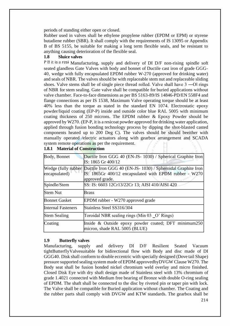
214
periods of standing either open or closed.
Rubber used in valves shall be ethylene propylene rubber (EPDM or EPM) or styrene
butadiene rubber (SBR). It shall comply with the requirements of IS 13095 or Appendix
B of BS 5155, be suitable for making a long term flexible seals, and be resistant to
anything causing deterioration of the flexible seal.
1.8 Sluice valves
Manufacturing, supply and delivery of DI D/F non-rising spindle soft
seated glandless Gate Valves with body and bonnet of Ductile cast iron of grade GGG-
40, wedge with fully encapsulated EPDM rubber W-270 (approved for drinking water)
and seals of NBR. The valves should be with replaceable stem nut and replaceable sliding
shoes. Valve stems shall be of single piece thread rolled. Valve shall have 3 ―O‖ rings
of NBR for stem sealing. Gate valve shall be compatible for buried applications without
valve chamber. Face-to-face dimensions as per BS 5163-89/IS 14846-PD/EN 558F4 and
flange connections as per IS 1538, Maximum Valve operating torque should be at least
40% less than the torque as stated in the standard EN 1074. Electrostatic epoxy
powder/liquid coating (EP-P) inside and outside color blue RAL 5005 with minimum
coating thickness of 250 microns. The EPDM rubber & Epoxy Powder should be
approved by W270. (EP-P, it is a resicoat powder approved for drinking water application,
applied through fusion bonding technology process by dipping the shot-blasted casted
components heated up to 200 Deg C). The valves should be should beeither with
manually operated /electric actuators along with gearbox arrangement and SCADA
system remote operations as per the requirement.
1.8.1 Material of Construction
Body, Bonnet Ductile Iron GGG 40 (EN-JS- 1030) / Spherical Graphite Iron
IS: 1865 Gr 400/12
Wedge (fully rubber
encapsulated)
Ductile Iron GGG 40 (EN-JS- 1030) / Spheroidal Graphite Iron
IS: 1865Gr 400/12 encapsulated with EPDM rubber - W270
approved grade.
Spindle/Stem SS: IS: 6603 12Cr13/22Cr 13; AISI 410/AISI 420
Stem Nut Brass
Bonnet Gasket EPDM rubber - W270 approved grade
Internal Fasteners Stainless Steel SS316/304
Stem Sealing Toroidal NBR sealing rings (Min 03 ‗O’ Rings)
Coating Inside & Outside epoxy powder coated; DFT minimum250
micron, shade RAL 5005 (BLUE)
1.9 Butterfly valves
Manufacturing, supply and delivery DI D/F Resilient Seated Vacuum
tightButterflyValvesuitable for bidirectional flow with Body and disc made of DI
GGG40. Disk shall conform to double eccentric with specially designed (Dove tail Shape)
pressure supported sealing system made of EPDM approvedbyDVGW Clause W270. The
Body seat shall be fusion bonded nickel chromium weld overlay and micro finished.
Closed Disk Eye with dry shaft design made of Stainless steel with 13% chromium of
grade 1.4021 connected with Medium free bearing of Bronze with double O-ring sealing
of EPDM. The shaft shall be connected to the disc by riveted pin or taper pin with lock.
The Valve shall be compatible for Buried application without chamber. The Coating and
the rubber parts shall comply with DVGW and KTW standards. The gearbox shall be
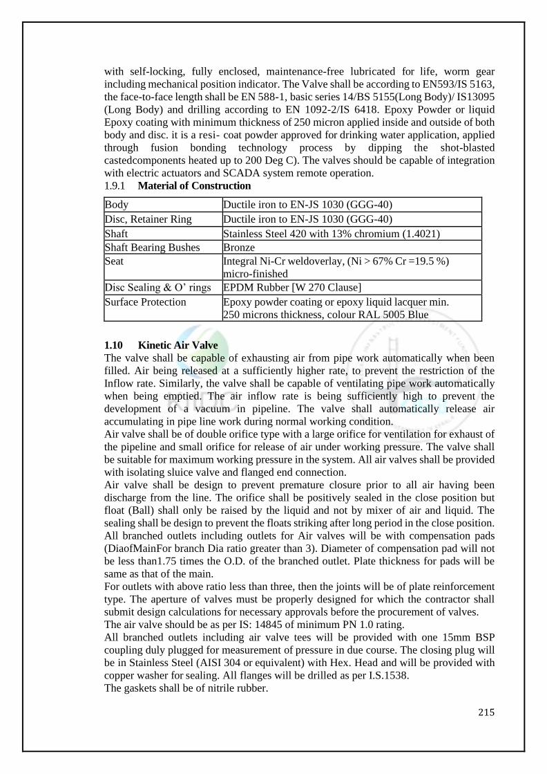
215
with self-locking, fully enclosed, maintenance-free lubricated for life, worm gear
including mechanical position indicator. The Valve shall be according to EN593/IS 5163,
the face-to-face length shall be EN 588-1, basic series 14/BS 5155(Long Body)/ IS13095
(Long Body) and drilling according to EN 1092-2/IS 6418. Epoxy Powder or liquid
Epoxy coating with minimum thickness of 250 micron applied inside and outside of both
body and disc. it is a resi- coat powder approved for drinking water application, applied
through fusion bonding technology process by dipping the shot-blasted
castedcomponents heated up to 200 Deg C). The valves should be capable of integration
with electric actuators and SCADA system remote operation.
1.9.1 Material of Construction
Body Ductile iron to EN-JS 1030 (GGG-40)
Disc, Retainer Ring Ductile iron to EN-JS 1030 (GGG-40)
Shaft Stainless Steel 420 with 13% chromium (1.4021)
Shaft Bearing Bushes Bronze
Seat Integral Ni-Cr weldoverlay, (Ni > 67% Cr =19.5 %)
micro-finished
Disc Sealing & O’ rings EPDM Rubber [W 270 Clause]
Surface Protection Epoxy powder coating or epoxy liquid lacquer min.
250 microns thickness, colour RAL 5005 Blue
1.10 Kinetic Air Valve
The valve shall be capable of exhausting air from pipe work automatically when been
filled. Air being released at a sufficiently higher rate, to prevent the restriction of the
Inflow rate. Similarly, the valve shall be capable of ventilating pipe work automatically
when being emptied. The air inflow rate is being sufficiently high to prevent the
development of a vacuum in pipeline. The valve shall automatically release air
accumulating in pipe line work during normal working condition.
Air valve shall be of double orifice type with a large orifice for ventilation for exhaust of
the pipeline and small orifice for release of air under working pressure. The valve shall
be suitable for maximum working pressure in the system. All air valves shall be provided
with isolating sluice valve and flanged end connection.
Air valve shall be design to prevent premature closure prior to all air having been
discharge from the line. The orifice shall be positively sealed in the close position but
float (Ball) shall only be raised by the liquid and not by mixer of air and liquid. The
sealing shall be design to prevent the floats striking after long period in the close position.
All branched outlets including outlets for Air valves will be with compensation pads
(DiaofMainFor branch Dia ratio greater than 3). Diameter of compensation pad will not
be less than1.75 times the O.D. of the branched outlet. Plate thickness for pads will be
same as that of the main.
For outlets with above ratio less than three, then the joints will be of plate reinforcement
type. The aperture of valves must be properly designed for which the contractor shall
submit design calculations for necessary approvals before the procurement of valves.
The air valve should be as per IS: 14845 of minimum PN 1.0 rating.
All branched outlets including air valve tees will be provided with one 15mm BSP
coupling duly plugged for measurement of pressure in due course. The closing plug will
be in Stainless Steel (AISI 304 or equivalent) with Hex. Head and will be provided with
copper washer for sealing. All flanges will be drilled as per I.S.1538.
The gaskets shall be of nitrile rubber.
216
1.11 Dismantling Joints
DI Double flanged Dismantling joints shall be installed in such a manner that valves can
be dismantled without stress to the joints. Dismantling joints shall be suitable for
installation with all valves of different diameters.
The dismantling joint shall be designed for a hydrostatic pressure of 10 kg/sq.cm. The
sliding flange shall be machined smooth and shall slide at least 30 mm to disengage fully
mating flange. All the fasteners for the dismantling joint shall be of SS 304. These shall
be completely leak proof with proper gasket arrangement. Flange dimensions shall
conform to latest relevant IS code. Flanged specials shall be supplied with required nuts,
bolts and rubber gaskets. The dismantling joint shall be internally and externally coated
with hot applied (dip) bituminous paint.
1.12 Ball Valves
Ball valves shall conform where applicable to IS 9890-2003 or BS5159.
Multi-piece bodies shall be used where work on the ball and seats when installed may be
needed. If valves need removal for servicing, one-piece bodies may be used.
Seat materials shall be chosen for long life, with erosion and corrosion resistance.
Ball supports shall be of the floating ball or trunnion type. If line pressure is too low to
ensure a positive leak-free seal, built-in seat loading devices, or specially shapedseating
shall be used to ensure sealing
1.13 PRESSURE REDUCING VALVES
The Pressure Reducing Valve should be capable of reducing higher pressure to lower pre
-set downstream pressure irrespective of flow or varying upstream pressure fluctuations.
The valve shall be globe/inline or angular pattern design. The body shall have a
replaceable, raised, stainless steel seat ring. The valve shall have an unobstructed flow
path with no stem guides, bearings, or supporting ribs. The body and cover shall be ductile
iron. All external bolts, nuts, and studs shall be Duplex coated. All valve components
shall be accessible andserviceable without removing the valve from the pipeline. The
main valve body internals shall consist of only three parts i.e. body, diaphragm and top
cover thus minimizing maintenance. The diaphragm shall provide uniform pressure
distribution around the sealing area and prevents deformation to diaphragm to ensure
longer maintenance free operation.
The valves should be of single/double chamber, self-actuating automatic valves and no
other external means either electrical/pneumatic should be required to operate the valve.
The entire actuator assembly (seal disk to top cover) shall be removable from the valve
as an integral unit. The internal valve component shall be accessible, removable and
repairable without removing the valve body from the pipeline. The stainless steel valve
shaft shall be center guided by a bearing in the separating partition. The valves should be
pilot operated, 2-way adjustable, capable of being preset at a constant outlet pressure from
a higher upstream pressure and they shall be drop-tight under no-flow conditions.
A pressure gauge shall be provided toindicate downstream pressure over the operating
range of the valve. Valve operation shall be controlled by the interaction of the inlet
pressure, outlet pressure and an intermediate pressure produced by a pilot valve or relay
system acting on the upper side of the main valve. Valves shall be flanged and drilled to
BS 4504 for the operating pressure required. The valve manufacturer shall be certified
according to the ISO 9001 Quality Assurance Standard. The valve should be of proven
design and should have been successfully installed and running in similar projects,
credentials should be submitted to prove the same, subject to approval of the owner.
Valves shall be flanged and drilled to BS 4504 for the operating pressure required.
1.13.1 Material of Construction
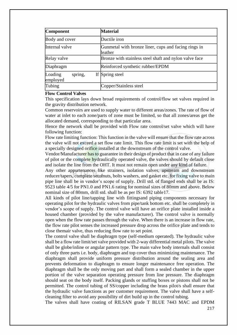
217
Component Material
Body and cover Ductile iron
Internal valve Gunmetal with bronze liner, cups and facing rings in
leather
Relay valve Bronze with stainless steel shaft and nylon valve face
Diaphragm Reinforced synthetic rubber/EPDM
Loading spring, If
employed
Spring steel
Tubing Copper/Stainless steel
Flow Control Valves
This specification lays down broad requirements of control/flow set valves required in
the gravity distribution network.
Common reservoirs are used to supply water to different areas/zones. The rate of flow of
water at inlet to each zone/parts of zone must be limited, so that all zones/areas get the
allocated demand, corresponding to that particular area.
Hence the network shall be provided with Flow rate control/set valve which will have
following function:
Flow rate limiting function: This function in the valve will ensure that the flow rate across
the valve will not exceed a set flow rate limit. This flow rate limit is set with the help of
a specially designed orifice installed at the downstream of the control valve.
Vendor/Manufacturer has to guarantee in their design of product that in case of any failure
of pilot or the complete hydraulically operated valve, the valves should by default close
and isolate the line from the OHT. It must not remain open under any kind of failure.
Any other appurtenances like strainers, isolation valves, upstream and downstream
reducer/tapers, complete setofnuts, bolts washers, and gasket etc. for fixing valve to main
pipe line shall be in vendor’s scope of supply. Drill std. of flanged ends shall be as IS:
9523 table 4/5 for PN1.0 and PN1.6 rating for nominal sizes of 80mm and above. Below
nominal size of 80mm, drill std. shall be as per IS: 6392 table17.
All kinds of pilot line/tapping line with fittingsand piping components necessary for
operating pilot for the hydraulic valves from pipe/tank bottom etc. shall be completely in
vendor’s scope of supply. The control valve will have an orifice plate installed inside a
housed chamber (provided by the valve manufacturer). The control valve is normally
open when the flow rate passes through the valve. When there is an increase in flow rate,
the flow rate pilot senses the increased pressure drop across the orifice plate and tends to
close themair valve, thus reducing flow rate to set point.
The control valve shall be diaphragm type (self-medium operated). The hydraulic valve
shall be a flow rate limit/set valve provided with 2-way differential metal pilots. The valve
shall be globe/inline or angular pattern type. The main valve body internals shall consist
of only three parts i.e. body, diaphragm and top cover thus minimizing maintenance. The
diaphragm shall provide uniform pressure distribution around the sealing area and
prevents deformation to diaphragm to ensure longer maintenance free operation. The
diaphragm shall be the only moving part and shall form a sealed chamber in the upper
portion of the valve separation operating pressure from line pressure. The diaphragm
should seat on the body itself. Packing glands or stuffing boxes or pistons shall not be
permitted. The control tubing of SS/copper including the brass pilot/s shall ensure that
the hydraulic valve functions as per customer requirement. The valve shall have a self-
cleaning filter to avoid any possibility of dirt build up in the control tubing.
The valves shall have coating of RILSAN grade T BLUE 7443 MAC and EPDM
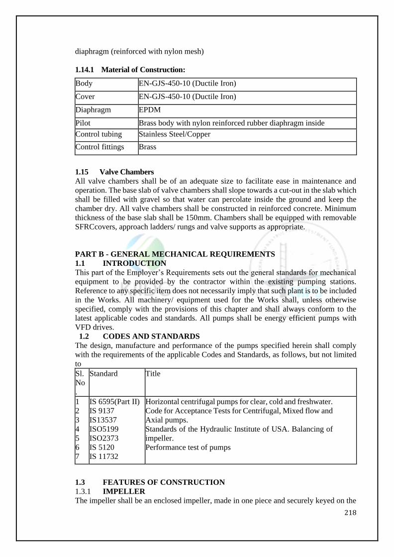
218
diaphragm (reinforced with nylon mesh)
1.14.1 Material of Construction:
Body EN-GJS-450-10 (Ductile Iron)
Cover EN-GJS-450-10 (Ductile Iron)
Diaphragm EPDM
Pilot Brass body with nylon reinforced rubber diaphragm inside
Control tubing Stainless Steel/Copper
Control fittings Brass
1.15 Valve Chambers
All valve chambers shall be of an adequate size to facilitate ease in maintenance and
operation. The base slab of valve chambers shall slope towards a cut-out in the slab which
shall be filled with gravel so that water can percolate inside the ground and keep the
chamber dry. All valve chambers shall be constructed in reinforced concrete. Minimum
thickness of the base slab shall be 150mm. Chambers shall be equipped with removable
SFRCcovers, approach ladders/ rungs and valve supports as appropriate.
PART B - GENERAL MECHANICAL REQUIREMENTS
1.1 INTRODUCTION
This part of the Employer’s Requirements sets out the general standards for mechanical
equipment to be provided by the contractor within the existing pumping stations.
Reference to any specific item does not necessarily imply that such plant is to be included
in the Works. All machinery/ equipment used for the Works shall, unless otherwise
specified, comply with the provisions of this chapter and shall always conform to the
latest applicable codes and standards. All pumps shall be energy efficient pumps with
VFD drives.
1.2 CODES AND STANDARDS
The design, manufacture and performance of the pumps specified herein shall comply
with the requirements of the applicable Codes and Standards, as follows, but not limited
to
Sl.
No
.
Standard Title
1
2
3
4
5
6
7
IS 6595(Part II)
IS 9137
IS13537
ISO5199
ISO2373
IS 5120
IS 11732
Horizontal centrifugal pumps for clear, cold and freshwater.
Code for Acceptance Tests for Centrifugal, Mixed flow and
Axial pumps.
Standards of the Hydraulic Institute of USA. Balancing of
impeller.
Performance test of pumps
1.3 FEATURES OF CONSTRUCTION
1.3.1 IMPELLER
The impeller shall be an enclosed impeller, made in one piece and securely keyed on the
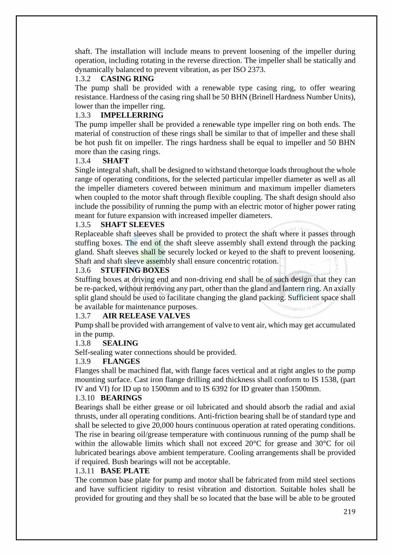
219
shaft. The installation will include means to prevent loosening of the impeller during
operation, including rotating in the reverse direction. The impeller shall be statically and
dynamically balanced to prevent vibration, as per ISO 2373.
1.3.2 CASING RING
The pump shall be provided with a renewable type casing ring, to offer wearing
resistance. Hardness of the casing ring shall be 50 BHN (Brinell Hardness Number Units),
lower than the impeller ring.
1.3.3 IMPELLERRING
The pump impeller shall be provided a renewable type impeller ring on both ends. The
material of construction of these rings shall be similar to that of impeller and these shall
be hot push fit on impeller. The rings hardness shall be equal to impeller and 50 BHN
more than the casing rings.
1.3.4 SHAFT
Single integral shaft, shall be designed to withstand thetorque loads throughout the whole
range of operating conditions, for the selected particular impeller diameter as well as all
the impeller diameters covered between minimum and maximum impeller diameters
when coupled to the motor shaft through flexible coupling. The shaft design should also
include the possibility of running the pump with an electric motor of higher power rating
meant for future expansion with increased impeller diameters.
1.3.5 SHAFT SLEEVES
Replaceable shaft sleeves shall be provided to protect the shaft where it passes through
stuffing boxes. The end of the shaft sleeve assembly shall extend through the packing
gland. Shaft sleeves shall be securely locked or keyed to the shaft to prevent loosening.
Shaft and shaft sleeve assembly shall ensure concentric rotation.
1.3.6 STUFFING BOXES
Stuffing boxes at driving end and non-driving end shall be of such design that they can
be re-packed, without removing any part, other than the gland and lantern ring. An axially
split gland should be used to facilitate changing the gland packing. Sufficient space shall
be available for maintenance purposes.
1.3.7 AIR RELEASE VALVES
Pump shall be provided with arrangement of valve to vent air, which may get accumulated
in the pump.
1.3.8 SEALING
Self-sealing water connections should be provided.
1.3.9 FLANGES
Flanges shall be machined flat, with flange faces vertical and at right angles to the pump
mounting surface. Cast iron flange drilling and thickness shall conform to IS 1538, (part
IV and VI) for ID up to 1500mm and to IS 6392 for ID greater than 1500mm.
1.3.10 BEARINGS
Bearings shall be either grease or oil lubricated and should absorb the radial and axial
thrusts, under all operating conditions. Anti-friction bearing shall be of standard type and
shall be selected to give 20,000 hours continuous operation at rated operating conditions.
The rise in bearing oil/grease temperature with continuous running of the pump shall be
within the allowable limits which shall not exceed 20°C for grease and 30°C for oil
lubricated bearings above ambient temperature. Cooling arrangements shall be provided
if required. Bush bearings will not be acceptable.
1.3.11 BASE PLATE
The common base plate for pump and motor shall be fabricated from mild steel sections
and have sufficient rigidity to resist vibration and distortion. Suitable holes shall be
provided for grouting and they shall be so located that the base will be able to be grouted
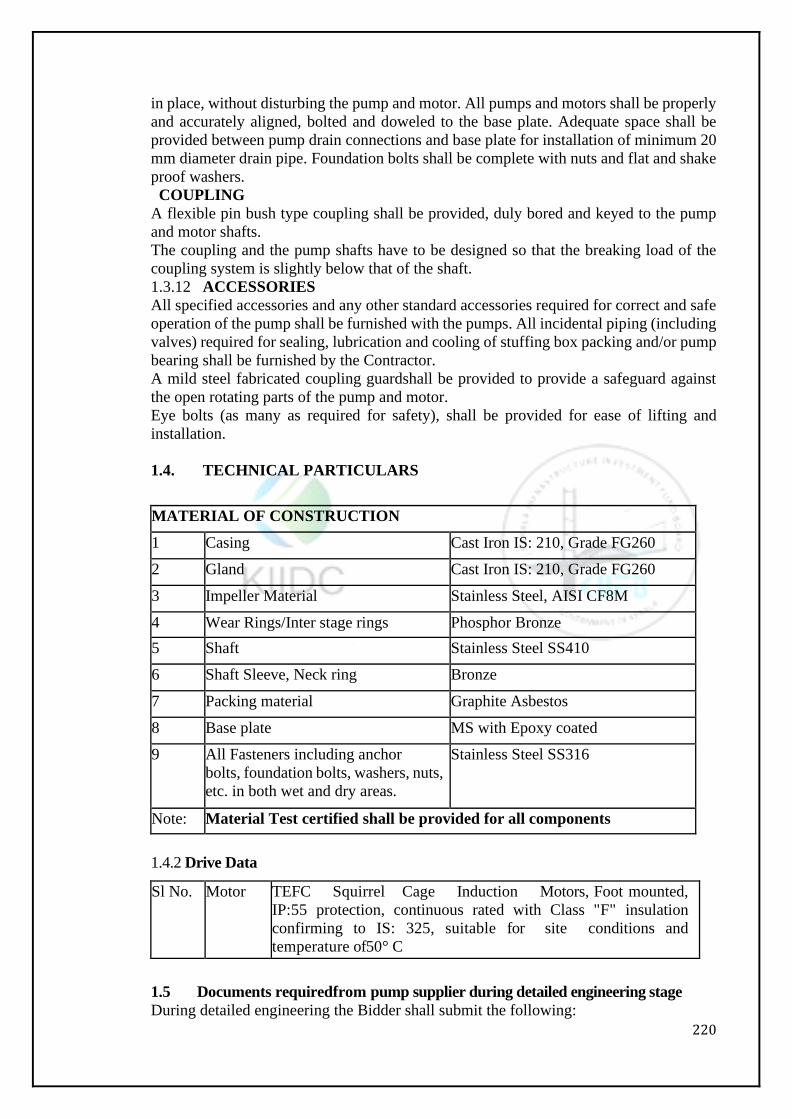
220
in place, without disturbing the pump and motor. All pumps and motors shall be properly
and accurately aligned, bolted and doweled to the base plate. Adequate space shall be
provided between pump drain connections and base plate for installation of minimum 20
mm diameter drain pipe. Foundation bolts shall be complete with nuts and flat and shake
proof washers.
COUPLING
A flexible pin bush type coupling shall be provided, duly bored and keyed to the pump
and motor shafts.
The coupling and the pump shafts have to be designed so that the breaking load of the
coupling system is slightly below that of the shaft.
1.3.12 ACCESSORIES
All specified accessories and any other standard accessories required for correct and safe
operation of the pump shall be furnished with the pumps. All incidental piping (including
valves) required for sealing, lubrication and cooling of stuffing box packing and/or pump
bearing shall be furnished by the Contractor.
A mild steel fabricated coupling guardshall be provided to provide a safeguard against
the open rotating parts of the pump and motor.
Eye bolts (as many as required for safety), shall be provided for ease of lifting and
installation.
1.4. TECHNICAL PARTICULARS
MATERIAL OF CONSTRUCTION
1 Casing Cast Iron IS: 210, Grade FG260
2 Gland Cast Iron IS: 210, Grade FG260
3 Impeller Material Stainless Steel, AISI CF8M
4 Wear Rings/Inter stage rings Phosphor Bronze
5 Shaft Stainless Steel SS410
6 Shaft Sleeve, Neck ring Bronze
7 Packing material Graphite Asbestos
8 Base plate MS with Epoxy coated
9 All Fasteners including anchor
bolts, foundation bolts, washers, nuts,
etc. in both wet and dry areas.
Stainless Steel SS316
Note: Material Test certified shall be provided for all components
1.4.2 Drive Data
Sl No. Motor TEFC Squirrel Cage Induction Motors, Foot mounted,
IP:55 protection, continuous rated with Class "F" insulation
confirming to IS: 325, suitable for site conditions and
temperature of50° C
1.5 Documents requiredfrom pump supplier during detailed engineering stage
During detailed engineering the Bidder shall submit the following:
221
CompletefilledupTechnicalDatasheetofPumpandmotorsprovidedwithPR.
Performance curves of individual pumps @ 50Hz frequency superimposed on system
curve at rated rpm.
Performance curves of individual pumps @ 53Hz frequency superimposed on system
curve at rated rpm
Pumps General arrangement drawing
Foundation Detail arrangement
Pump Cross section drawing
Motor technical datasheet
Motorperformance curves
Motor General arrangement drawing
Motor cross section drawing
DRIVER TORQUE VS SPEED SUPERIMPOSED ON LOAD TORQUE VS
SPEEDCURVE
SPEED VSCURRENT
WITHSTAND TIME VS MOTOR CURRENT
EFFCIENCY VS % OF LOAD
POWER FACTOR VS % OF LOAD
TERMINAL BOX GA
RESISTANCE VS TEMPARATURE
1.6 Accessories and scope of supply
The supply of pumps and accessories shall include the following but not limited to
Pumps complete with casing and volute assembly and impeller, Motor, shafts, Shaft
sleeves, Gland packing, Bearingassembly, Coupling, Coupling guard, Base plate,
Foundation bolts, fittings, Fasteners, Inserts, Name plates, Companion flanges etc.
complete for successful commissioning of pumps.
Consumables, Commissioning spares, lubricants, Mandatory spares, surface preparation,
painting, shop testing, site testing, shop testing facilities
Compound and Pressure Gauge: 150/200 mm Dia. of suitable range with stainless steel
connecting pipes, gooseneck, cocks etc. complete.
Priming Cock.
Suitable piping for collection and leading off gland leaks etc. up to discharge point.
Priming Cock.
At least one working and one standby unit of vacuum pump + motor of suitable capacity
and rating for priming arrangements of main pumps complete with all piping accessories
and connection and potable water tank.
1.7 Pump Performance Guarantees
The pump performance guarantee shall relate to the flow rate, the total head and the
efficiency of the pump when tested at the manufacturer's work and shall obtain approval
of Engineer.
The pump shall operate at its design point within acceptance tolerances for flow rate and
total head laid down in BS EN ISO 9906:2000.
Each pump shall be tested at the manufacturer's factory in accordance with BS EN ISO
9906:2000 or other relevant standards in conjunction with one of the contract motors.
This test shall be carried out on at least one pump set using the flexible coupling and
contract drive shaft arrangement to establish that the drive arrangement with supports and
couplings operates satisfactorily under all operating conditions.
Where similar drive shaft arrangements have been installed by the Contractor and have
been proven satisfactory in service this requirement may be withdrawn subject to the
approval of the Engineer.
222
A test shall be carried out of the performance from closed valve to the maximum quantity
that can be delivered under abnormally low discharge heads.
Sufficient readings shall be taken at each test to produce accurate curves of the heads,
flow, pump speed and power required at pump coupling throughout the operating range
of the pump. Vibration and noise dB (A) levels shall be measured and shown to be
acceptable and shall have Engineer’s approval. The Contractor shall have Engineer
approval and provide acceptable test certificates, showing the NPSH requirement for the
pump is at least 2 m less than the NPSH available under all working conditions.
In the absence of the approved test certificates the supplier shall carry out a test on one
pump of each type to verify the NPSH requirement based upon the 3% output drop
criterion and shall take approval of Employers Engineer.
Test Certificates in duplicate shall be submitted to the Engineer immediately following
each of the tests mentioned above. Performance curves shall also be incorporated in the
Operation and Maintenance Manual.
Single PumpOperation
Head/quantity curve
Motor kW input/quantity curve
Overall efficiency/quantity curve
NPSH required/quantity curve
Vibration and Noise dB (A)levels
Parallel PumpOperation
Head/quantity curves
Motor kW input/quantity curve
Overall efficiency/quantity curve
NPSH required/quantity curve
Vibration and noise dB(A) levels
may be made from pressed sheet steel with roller type guarding. Gears shall be cut from
solid cast or forged steel blanks or shall be stress – relieved welded steel construction.
Pinions shall be of forged carbon or heat treatedalloy steel. Strength, Quality of Steel,
heat treatment, face, pitch of teeth and design shall confirm to BS-436, BS-545 and BS-
721. Spur and helical gears must comply with B.S. 436 and worm with B.S. 721. Bearing
must be ball and roller type conforming to I.S. 2513/B.S.2525-32:1954. Proper
lubricating arrangements are to be provided for bearings and pinions. The brake for the
lifting gear shall be automatic and always inaction. The proof testing of each chain pulley
block is to be carried out as per latest applicable standards. The safe working load is to
be marked in such way that is clearly visible from the operating level.
PART C – ROAD RESTORATION
Road restoration is a critical activity which requires special attention of the contractor.
Following guidelines should be followed:
The contractor shall have to restore the road up to WMM stage including refilling trench
in layers, watering, rolling and compacting to within 10days after trenching is completed
in a particular street/reach. The contractor shall ensure that uncovered WBM length in
total does not exceed 5.0KM at any stage of work and will complete the bituminous work
regularly.
Contractor shall erect informatory board at his own cost showing type of work,
inconvenience expected & timeline for various construction activities going to take place
in a particular streetoraparticular reach of road as per direction of Engineer in charge.
Contractor shall deploy a community outreach team headed by a qualified social expert
223
(post graduate in sociology) having minimum 3 years’ experience of social activity work
with government recognized NGO or other government institutes to make strong relation
with public prior to start of work in a particular ward/area.
The contractor shall have to do the sequencing of activities as per direction of engineer in
charge to synchronize pipe line work to minimize the road excavation and restoration in
the street which will have pipelines.
The cutting of existing C.C. pavement shall be done by using mechanical cutter to ensure
cutting in regular line and the laying of C.C pavement shall be done below 30
degreeambient temperature.
All Work shall be as per MoRTHspecifications.
Provisions of road restoration:
(i) For laying water supply pipe on B/T Surface
For road width up to 4 m, restoration up to WMM stage in trench width and bituminous
work (wearing surface) in full width of the Existing Road.
For road width 4 m to7 m, restoration up to WMM stage in trench width and bituminous
work (wearing surface) in entire road width up to 7 m.
For road width more than 7 m, restoration limited to 7 m (2 lanes) to cover the trenches
(may be one lane over each trench).
(ii) For laying water supply pipe on CC Road:-
For road width less than 4.0m, restoration up to PCC stage (lean concrete) will be in
trench width & CC pavement of M-30 grade in full width.
For road width more than 4.0m, restoration by lean concrete and pavement in M-30grade
in trench width only.
In Bituminous road restoration, Use of Paver is mandatory for carriage way width above
3.75m of road restoration
Notwithstanding all which has been laid down on road restoration, Employer’s
representative with reasons recorded and prior permission of PIU in charge will be
authorized to come up with the site specific solution based on prevailing ground situation.
PART D – BUILDINGS/CIVIL
The work should be carried out as per the approved design, drawings and specifications.
The contractor should follow Kerala Detailed Standard Specifications and Central Public
Works Department (CPWD) Specifications.
All relevant provisions of IS codes should be strictly adhered.

224
Volume 3: Financial Bid

230
Section - 9: Financial Forms
231
SECTION – IX
Financial Forms
FORM OF TENDER (Price Bid)
(To be quoted by the Bidder)
Name of Contract "KIIFB – KIIDC – Extension of Moolathara Right Bank Canal
from Korayar to Varattayar."(Civil Works)
To,
The Managing Director, Kerala Irrigation Infrastructure Development Corporation Limited (KIIDC), PARVATHY, TC 36 /1, NH 66 Service Road, Eanchakkal, Chakkai P O, Thiruvananthapuram -696024, Kerala Email: [email protected]
Having examined the Conditions of Contract, Specifications, Drawings and Addenda for the execution of the above named Works, we, the undersigned, offer to survey, design, execute and complete such Works and remedy any defects therein in conformity with the Conditions of Contract, Specifications, Drawings, Design Criteria, Scope of Work and Addenda for the sum of Rs. ………………………………. (In words: Rupees …………..)or such other sum as may be ascertained in accordance with the said Conditions. We acknowledge that the Volume I, Volume II, Volume III and Volume – IV form part of Tender. We undertake, if our Tender is accepted, to commence the Works as soon as is reasonably possible after the receipt of the Engineer’s notice to commence, and to complete the whole of the Works comprised in the contract within 30months as stipulated in the Tender. We agree to abide by this Tender for the period of 180 days from the date fixed for receiving the same and it shall remain binding upon us and may be accepted at any time before the expiration of thatperiod. The contract is not complete and binding between us unless and until a formal Agreement is prepared and executed for this Tender, together with your written acceptancethereof. We understand that you are not bound to accept the lowest or any tender you may receive. Dated this……………………day of 2020 Signature ……………………………in the capacity of …………………………… Duly authorized to sign tenders for and on behalf of ………………………… Address….………………………………………………………………………… Occupation. …………………………………………..
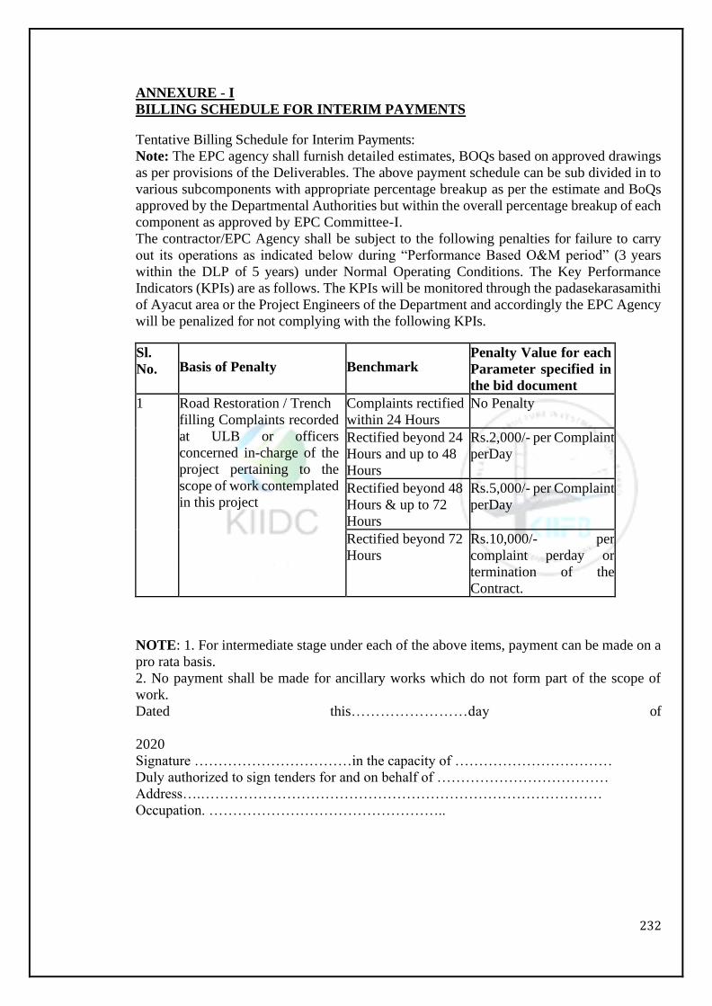
232
ANNEXURE - I
BILLING SCHEDULE FOR INTERIM PAYMENTS
Tentative Billing Schedule for Interim Payments:
Note: The EPC agency shall furnish detailed estimates, BOQs based on approved drawings
as per provisions of the Deliverables. The above payment schedule can be sub divided in to
various subcomponents with appropriate percentage breakup as per the estimate and BoQs
approved by the Departmental Authorities but within the overall percentage breakup of each
component as approved by EPC Committee-I.
The contractor/EPC Agency shall be subject to the following penalties for failure to carry
out its operations as indicated below during “Performance Based O&M period” (3 years
within the DLP of 5 years) under Normal Operating Conditions. The Key Performance
Indicators (KPIs) are as follows. The KPIs will be monitored through the padasekarasamithi
of Ayacut area or the Project Engineers of the Department and accordingly the EPC Agency
will be penalized for not complying with the following KPIs.
Sl.
No.
Basis of Penalty
Benchmark Penalty Value for each
Parameter specified in
the bid document
1 Road Restoration / Trench
filling Complaints recorded
at ULB or officers
concerned in-charge of the
project pertaining to the
scope of work contemplated
in this project
Complaints rectified
within 24 Hours
No Penalty
Rectified beyond 24
Hours and up to 48
Hours
Rs.2,000/- per Complaint
perDay
Rectified beyond 48
Hours & up to 72
Hours
Rs.5,000/- per Complaint
perDay
Rectified beyond 72
Hours
Rs.10,000/- per
complaint perday or
termination of the
Contract.
NOTE: 1. For intermediate stage under each of the above items, payment can be made on a
pro rata basis.
2. No payment shall be made for ancillary works which do not form part of the scope of
work.
Dated this……………………day of
2020
Signature ……………………………in the capacity of ……………………………
Duly authorized to sign tenders for and on behalf of ………………………………
Address….…………………………………………………………………………
Occupation. …………………………………………..
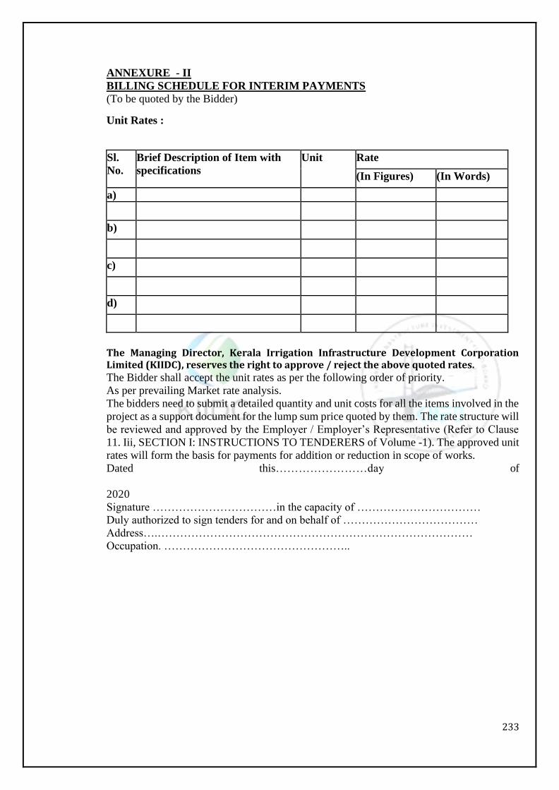
233
ANNEXURE - II
BILLING SCHEDULE FOR INTERIM PAYMENTS
(To be quoted by the Bidder)
Unit Rates :
Sl.
No.
Brief Description of Item with
specifications
Unit Rate
(In Figures) (In Words)
a)
b)
c)
d)
The Managing Director, Kerala Irrigation Infrastructure Development Corporation Limited (KIIDC), reserves the right to approve / reject the above quoted rates. The Bidder shall accept the unit rates as per the following order of priority.
As per prevailing Market rate analysis.
The bidders need to submit a detailed quantity and unit costs for all the items involved in the
project as a support document for the lump sum price quoted by them. The rate structure will
be reviewed and approved by the Employer / Employer’s Representative (Refer to Clause
11. Iii, SECTION I: INSTRUCTIONS TO TENDERERS of Volume -1). The approved unit
rates will form the basis for payments for addition or reduction in scope of works.
Dated this……………………day of
2020
Signature ……………………………in the capacity of ……………………………
Duly authorized to sign tenders for and on behalf of ………………………………
Address….…………………………………………………………………………
Occupation. …………………………………………..
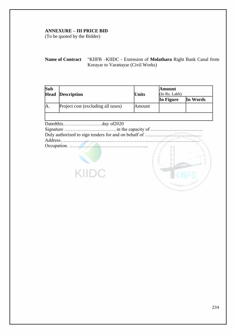
234
ANNEXURE – III PRICE BID
(To be quoted by the Bidder)
Name of Contract "KIIFB –KIIDC - Extension of Molathara Right Bank Canal from
Korayar to Varattayar (Civil Works)
Sub
Head
Description
Units
Amount (In Rs. Lakh)
In Figure In Words
A. Project cost (excluding all taxes) Amount
Datedthis……………………day of2020
Signature ……………………………in the capacity of ……………………………
Duly authorized to sign tenders for and on behalf of ………………………………
Address….…………………………………………………………………………
Occupation. …………………………………………..

235
THIS PAGE HAS BEEN LEFT BLANK
INTENTIONALLY
236
Volume 4: Bidder Model Forms

237
In model forms data to be filled by the Bidder.
If need be additional sheets can be added.
238
Section - 10: Bidding Forms
239
SECTION – X
Bidding Forms
240
DATA SHEET –1
Bidder’s Appreciation of the Project
This should also consist of a report on the Bidder’s appreciation of the project, which should
include a section on the site inspection carried out prior to bidding, and demonstrate
awareness and understanding of all the principle technical and logistic aspects related to
project construction.
241
DATA SHEET –2
Bidder’s Organizational Setup for the Project
The bidder should provide the following information
A. Preliminary organization chart
for Overall project management
Surveys and detailed
investigation Design and
engineering services
Execution of Civil works, water supply pipe lines and road works.
Quality assurance system
Testing and commissioning
B. Narrative description of organization chart
C. Description of relationship between Head office and site management.
242
DATA SHEET –3
Drawings to be submitted
The bidder shall submit, descriptions of proposed project components, adhering to the basic
parameters indicated in the bid document along with relevant drawings. The information
should be submitted in sufficient details to allow an assessment of the general adequacy of
the Bidder’s proposals, Sketches, drawings and diagrams along with salient design details,
where necessary should be included.
243
DATA SHEET –4
Management of Design and Engineering Services
The bidder shall submit descriptions of proposed management of Surveys, Detailed
investigation, Design and Engineering services and sequences to be used for the same. Key
surveys, detailed investigation and soil exploration activities, key design and engineering
activities, Key experts for the same and their deployment schedule should be identified and
described. This information shall be given separately for water supply, sewerage and road
works.
244
DATA SHEET –5
Construction Methodology of different structural components
The bidder shall submit in brief descriptions of proposed methods, sequences, facilities
and layouts to be used for execution of water supply, sewerage and road works. This
should cover the following.
Working facilities
Infrastructure works Civil
works
Water supply
Road work
The information submitted should be such as to allow an assessment of the general
adequacy of the Bidder’s proposal. The information shall include number and
classification of manpower, equipment and materials proposed to be deployed for each of
the branch activities.
245
DATA SHEET –6
Proposed Deployment of Key Personnel
For specific positions essential to contract implementation, the bidder should provide the
proposed deployment of key personnel (for Surveys, Detailed Investigation, Soil
Exploration, Design and Engineering, Civil construction, Hydro-mechanical works, E & M
works). Bio-Data of each of the personnel proposed to be deployed for various activities
shall be included in separate sheets for each candidate.
Name of Tenderer
Sl.
No.
Name of
Person
Designation/ Post
Held/ Status
Academic Qualifications
and Experiences in
Similar Works.
Remarks
Signature of Tenderer
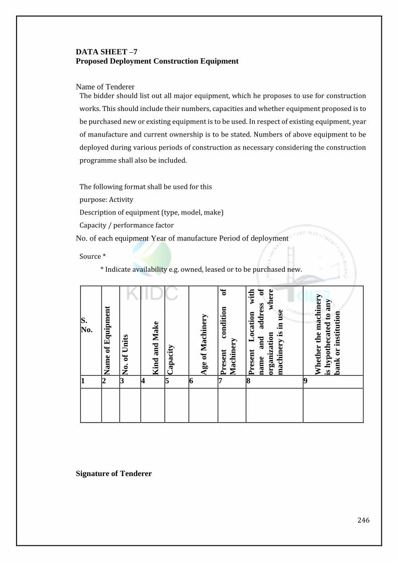
246
DATA SHEET –7
Proposed Deployment Construction Equipment
Name of Tenderer The bidder should list out all major equipment, which he proposes to use for construction
works. This should include their numbers, capacities and whether equipment proposed is to
be purchased new or existing equipment is to be used. In respect of existing equipment, year
of manufacture and current ownership is to be stated. Numbers of above equipment to be
deployed during various periods of construction as necessary considering the construction
programme shall also be included.
The following format shall be used for this
purpose: Activity
Description of equipment (type, model, make)
Capacity / performance factor
No. of each equipment Year of manufacture Period of deployment
Source *
* Indicate availability e.g. owned, leased or to be purchased new.
S.
No.
Nam
e of
Eq
uip
men
t
No. of
Un
its
Kin
d a
nd
Mak
e
Cap
aci
ty
Age
of
Ma
chin
ery
Pre
sen
t co
nd
itio
n
of
Mach
iner
y
Pre
sen
t L
oca
tion
w
ith
nam
e an
d
ad
dre
ss
of
org
an
izati
on
w
her
e
mach
iner
y i
s in
use
Wh
eth
er t
he
ma
chin
ery
is h
yp
oth
ecate
d t
o a
ny
ban
k o
r in
stit
uti
on
1 2 3 4 5 6 7 8 9
Signature of Tenderer
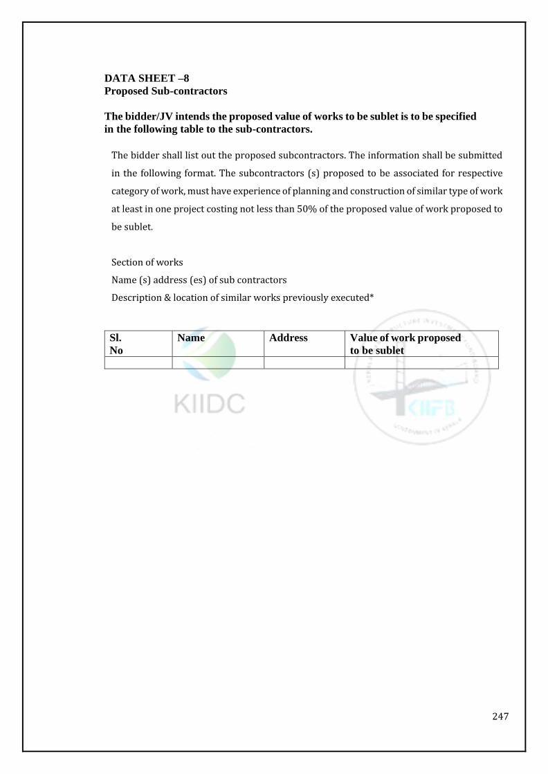
247
DATA SHEET –8
Proposed Sub-contractors
The bidder/JV intends the proposed value of works to be sublet is to be specified
in the following table to the sub-contractors.
The bidder shall list out the proposed subcontractors. The information shall be submitted
in the following format. The subcontractors (s) proposed to be associated for respective
category of work, must have experience of planning and construction of similar type of work
at least in one project costing not less than 50% of the proposed value of work proposed to
be sublet.
Section of works
Name (s) address (es) of sub contractors
Description & location of similar works previously executed*
Sl.
No
Name Address Value of work proposed
to be sublet
248
DATA SHEET –9
Proposed Sourcing of Key Engineering Materials
The bidder shall submit, in outline, descriptions of proposed sourcing of key materials.
249
DATA SHEET –10
Proposed Construction Schedule for the Project
The bidder shall submit a construction program in bar chart from – together with
corresponding critical path network, which starts at the date of commencement and shows
in details all the key activities.

250
DATA SHEET –11
Quality Control and Quality Assurance System
The bidder shall submit, in outline, description of proposed quality control and quality
assurance system for the implementation of the project. This shall also include the proposed
testing laboratories with the testing equipment, key personnel for filed quality control and
inspection and laboratory work.
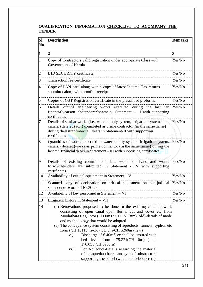
251
QUALIFICATION INFORMATION CHECKLIST TO ACOMPANY THE
TENDER
Sl.
No
Description Remarks
1 2 3
1 Copy of Contractors valid registration under appropriate Class with
Government of Kerala
Yes/No
2 BID SECURITY certificate Yes/No
3 Transaction fee certificate Yes/No
4 Copy of PAN card along with a copy of latest Income Tax returns
submittedalong with proof of receipt
Yes/No
5 Copies of GST Registration certificate in the prescribed proforma Yes/No
6 Details ofcivil engineering works executed during the last ten
financialyearson thetenderer’snamein Statement - I with supporting
certificates
Yes/No
7 Details of similar works (i.e., water supply system, irrigation system,
canals, (deleted) etc.) completed as prime contractor (in the same name)
during thelasttenfinanciall years in Statement-II with supporting
certificates
Yes/No
8 Quantities of works executed in water supply system, irrigation system,
canals, (deleted)works as prime contractor (in the same name) during the
last ten financial years in Statement - III with supporting certificates
Yes/No
9 Details of existing commitments i.e., works on hand and works
forwhichtenders are submitted in Statement - IV with supporting
certificates
Yes/No
10 Availability of critical equipment in Statement – V Yes/No
11 Scanned copy of declaration on critical equipment on non-judicial
stamppaper worth of Rs.200/-
Yes/No
12 Availability of key personnel in Statement – VI Yes/No
13 Litigation history in Statement – VII Yes/No
14 (d) Renovations proposed to be done in the existing canal network
consisting of open canal open flume, cut and cover etc from
Moolathara Regulator (CH 0m to CH 15118m) (old)-details of mode
and methodology that would be adopted.
(e) The conveyance system consisting of aqueducts, tunnels, syphon etc
from (CH 15118 m-old) CH 0m-CH 6260m,(new)
v.) Discharge of 6.40m3/sec shall be ensured with
bed level from 175.221(CH 0m) ) to
170.050(CH 6260m)
vi.) For Aqueduct-Details regarding the material
of the aqueduct barrel and type of substructure
supporting the barrel (whether steel/concrete)
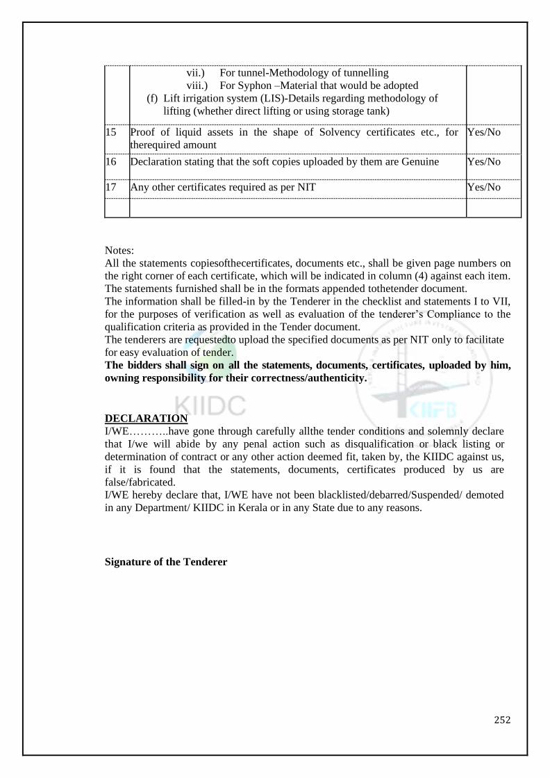
252
vii.) For tunnel-Methodology of tunnelling
viii.) For Syphon –Material that would be adopted
(f) Lift irrigation system (LIS)-Details regarding methodology of
lifting (whether direct lifting or using storage tank)
15 Proof of liquid assets in the shape of Solvency certificates etc., for
therequired amount
Yes/No
16 Declaration stating that the soft copies uploaded by them are Genuine Yes/No
17 Any other certificates required as per NIT Yes/No
Notes:
All the statements copiesofthecertificates, documents etc., shall be given page numbers on
the right corner of each certificate, which will be indicated in column (4) against each item.
The statements furnished shall be in the formats appended tothetender document.
The information shall be filled-in by the Tenderer in the checklist and statements I to VII,
for the purposes of verification as well as evaluation of the tenderer’s Compliance to the
qualification criteria as provided in the Tender document.
The tenderers are requestedto upload the specified documents as per NIT only to facilitate
for easy evaluation of tender.
The bidders shall sign on all the statements, documents, certificates, uploaded by him,
owning responsibility for their correctness/authenticity.
DECLARATION
I/WE………..have gone through carefully allthe tender conditions and solemnly declare
that I/we will abide by any penal action such as disqualification or black listing or
determination of contract or any other action deemed fit, taken by, the KIIDC against us,
if it is found that the statements, documents, certificates produced by us are
false/fabricated.
I/WE hereby declare that, I/WE have not been blacklisted/debarred/Suspended/ demoted
in any Department/ KIIDC in Kerala or in any State due to any reasons.
Signature of the Tenderer
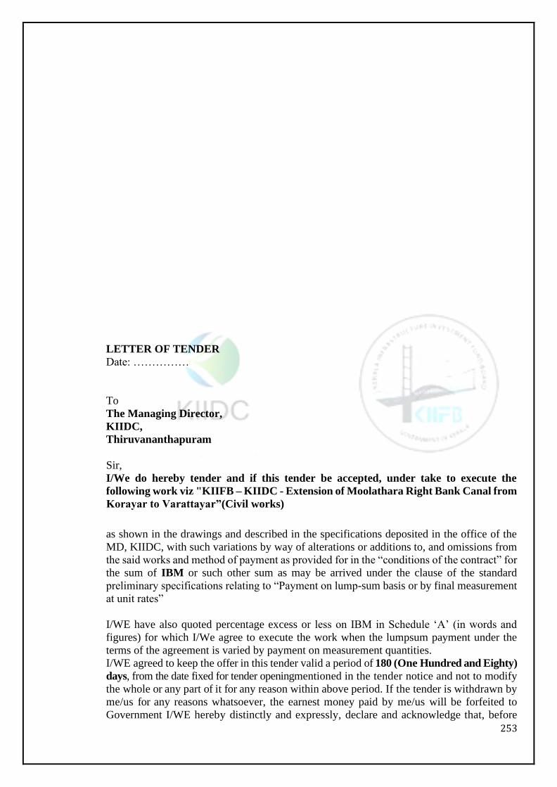
253
LETTER OF TENDER
Date: ……………
To
The Managing Director,
KIIDC,
Thiruvananthapuram
Sir,
I/We do hereby tender and if this tender be accepted, under take to execute the
following work viz "KIIFB – KIIDC - Extension of Moolathara Right Bank Canal from
Korayar to Varattayar”(Civil works)
as shown in the drawings and described in the specifications deposited in the office of the
MD, KIIDC, with such variations by way of alterations or additions to, and omissions from
the said works and method of payment as provided for in the “conditions of the contract” for
the sum of IBM or such other sum as may be arrived under the clause of the standard
preliminary specifications relating to “Payment on lump-sum basis or by final measurement
at unit rates”
I/WE have also quoted percentage excess or less on IBM in Schedule ‘A’ (in words and
figures) for which I/We agree to execute the work when the lumpsum payment under the
terms of the agreement is varied by payment on measurement quantities.
I/WE agreed to keep the offer in this tender valid a period of 180 (One Hundred and Eighty)
days, from the date fixed for tender openingmentioned in the tender notice and not to modify
the whole or any part of it for any reason within above period. If the tender is withdrawn by
me/us for any reasons whatsoever, the earnest money paid by me/us will be forfeited to
Government I/WE hereby distinctly and expressly, declare and acknowledge that, before
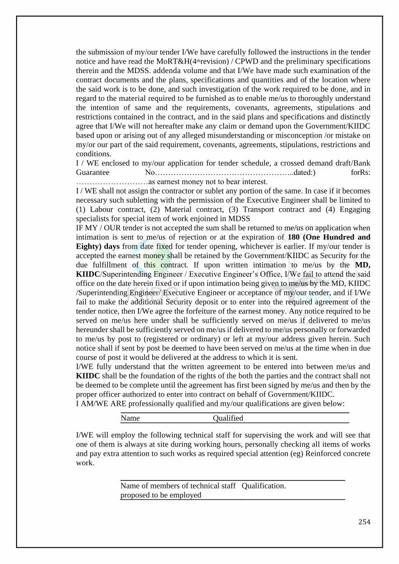
254
the submission of my/our tender I/We have carefully followed the instructions in the tender
notice and have read the MoRT&H(4threvision) / CPWD and the preliminary specifications
therein and the MDSS. addenda volume and that I/We have made such examination of the
contract documents and the plans, specifications and quantities and of the location where
the said work is to be done, and such investigation of the work required to be done, and in
regard to the material required to be furnished as to enable me/us to thoroughly understand
the intention of same and the requirements, covenants, agreements, stipulations and
restrictions contained in the contract, and in the said plans and specifications and distinctly
agree that I/We will not hereafter make any claim or demand upon the Government/KIIDC
based upon or arising out of any alleged misunderstanding or misconception /or mistake on
my/or our part of the said requirement, covenants, agreements, stipulations, restrictions and
conditions.
I / WE enclosed to my/our application for tender schedule, a crossed demand draft/Bank
Guarantee No……………………………………………..dated:) forRs:
………………………as earnest money not to bear interest.
I / WE shall not assign the contractor or sublet any portion of the same. In case if it becomes
necessary such subletting with the permission of the Executive Engineer shall be limited to
(1) Labour contract, (2) Material contract, (3) Transport contract and (4) Engaging
specialists for special item of work enjoined in MDSS
IF MY / OUR tender is not accepted the sum shall be returned to me/us on application when
intimation is sent to me/us of rejection or at the expiration of 180 (One Hundred and
Eighty) days from date fixed for tender opening, whichever is earlier. If my/our tender is
accepted the earnest money shall be retained by the Government/KIIDC as Security for the
due fulfillment of this contract. If upon written intimation to me/us by the MD,
KIIDC/Superintending Engineer / Executive Engineer’s Office, I/We fail to attend the said
office on the date herein fixed or if upon intimation being given to me/us by the MD, KIIDC
/Superintending Engineer/ Executive Engineer or acceptance of my/our tender, and if I/We
fail to make the additional Security deposit or to enter into the required agreement of the
tender notice, then I/We agree the forfeiture of the earnest money. Any notice required to be
served on me/us here under shall be sufficiently served on me/us if delivered to me/us
hereunder shall be sufficiently served on me/us if delivered to me/us personally or forwarded
to me/us by post to (registered or ordinary) or left at my/our address given herein. Such
notice shall if sent by post be deemed to have been served on me/us at the time when in due
course of post it would be delivered at the address to which it is sent.
I/WE fully understand that the written agreement to be entered into between me/us and
KIIDC shall be the foundation of the rights of the both the parties and the contract shall not
be deemed to be complete until the agreement has first been signed by me/us and then by the
proper officer authorized to enter into contract on behalf of Government/KIIDC.
I AM/WE ARE professionally qualified and my/our qualifications are given below:
Name Qualified
I/WE will employ the following technical staff for supervising the work and will see that
one of them is always at site during working hours, personally checking all items of works
and pay extra attention to such works as required special attention (eg) Reinforced concrete
work.
Name of members of technical staff
proposed to be employed
Qualification.
255
I/WE declare that I/WE agree to recover the salaries of the technical staff actually engaged
on the work by the Department / KIIDC, from the work bills, if I/We fail to employ technical
staff as per the tender condition.
TENDERERS / CONTRACTOR’S CERTIFICATE
I/WE hereby declare that I/We have perused in detail and examined closely the MoRT&H
(4thRevision) and Madrass Standard Specifications, all clauses of the preliminary
specifications with all amendments and have either examined all the standards specifications
or will examine all the standard specifications for items for which I/We tender, before I/We
submit such tender and agree to be bound and comply with all such specifications for this
agreement which I/We execute.
I/WE certify that I/We have inspected the site of the work before quoting my Percentage
excess or less on ECV, I /We have satisfied about the quality, availability and transport
facilities for coarse aggregate, sand and other materials.
I / WE am/are prepared tofurnishdetaileddatain support of all my quoted rates, if and when
called upon to do so without any reservations.
I / WE hereby declare that I / We will pay an Additional Security Deposit (ASD) in terms
of condition 3.6 of instructions to tenderers.
I / WE hereby declare that I am / we are accepting to reject my tender in terms of condition
3.7 of instructions to tenderers.
I / WE hereby declare that I / We will not claim any price escalation.
I / WE hereby declare that I am / We are accepting for the defect liability period as 30
months.
I / WE declare that I/WE will procure the required construction materials including earth
and use for the work after approval of the Engineer-in-Charge. The responsibility for
arranging and obtaining the land for borrowing or exploitation in any other way shall rest
with me/us for the materials for construction, I/WE shall ensure smooth and un-interrupted
supply of materials.
I / WE declare that the responsibility for arranging and obtaining the land for
disposalofspoil/soilnotusefulforconstructionpurposesshallrestwithme/us.
I / WE declare that I / WE shall not claim any compensation or any payment for the land so
arranged for disposal of soil and the land for borrow area. My/our quoted percentage excess
or less ECV are inclusive of the land so arranged and I/We will hand over the land so
arranged for disposal of soil to the KIIDCAuthority after completion of work.
I / WE declare that I / WE will not claim any extra amount towards any material used for
the work other than the quoted works for respective schedule ‘A’ items.
I / WE declare that I / WE will execute the work as per the mile stone programme, and if I /
WE fail to complete the work as per the mile stone programme I abide by the condition to
recover liquidated damages as per the tender conditions.
I / WE declare that I / WE will abide for settlement of disputes as per the tender conditions.
DECLARATION OF THE TENDERER
I/WE have not been black listed in any KIIDCinKerala due to any reasons.
I/WE have not been demoted to the next lower category for not filing the tenders after buying
the tender schedules in a whole year and my/our registration has not been cancelled for a
similar default in two consecutive years.
I/WE agree to disqualify me/us for any wrong declaration in respect of the above and to
summarily reject my/our tender.
I/WE have gone through carefully all the tender conditions and solemnly declare that I/WE
will abide by any penal action such as disqualification or black listing or determination of
contract or any other action deemed fit, taken by, the Department against us, if it is found
that the statements, documents, certificates produced by us are false/fabricated.
256
I/WE hereby declare that, I/WE have not been blacklisted/ debarred/ Suspended/ demoted
in any Department in Kerala ordinary State due to any reasons.
Address of the Tenderer: Signature of the tenderer
Phone No.:
Fax No.:
TECHNICAL BID
QUALIFICATION INFORMATION
The information shall be filled in by the Tenderer in the check slip and statements I to VI
and enclosed to the Technical bid/Tender schedules which will be sued for the purposes of
verification of adequacy of information as well as evaluating the tenderer’s Compliance to
the qualification criteria as provided in the Tender in the Tender Schedule. All the Statement
and check-slip shall be submitted by the tenderer in scaled cover ‘A’.
STATUS OF BIDDER
Individual/Partnership Firm
:
Place of Registration:
Principal Place of Business:
Registration particulars withGovernmentof Kerala:
Authorized signatory to sign theTender document in case the firm is:
the Tenderer (enclose copy of such authorization)
Check-slip duly filled in:Enclosed / Not enclosed

257
Signature of the Tenderer.
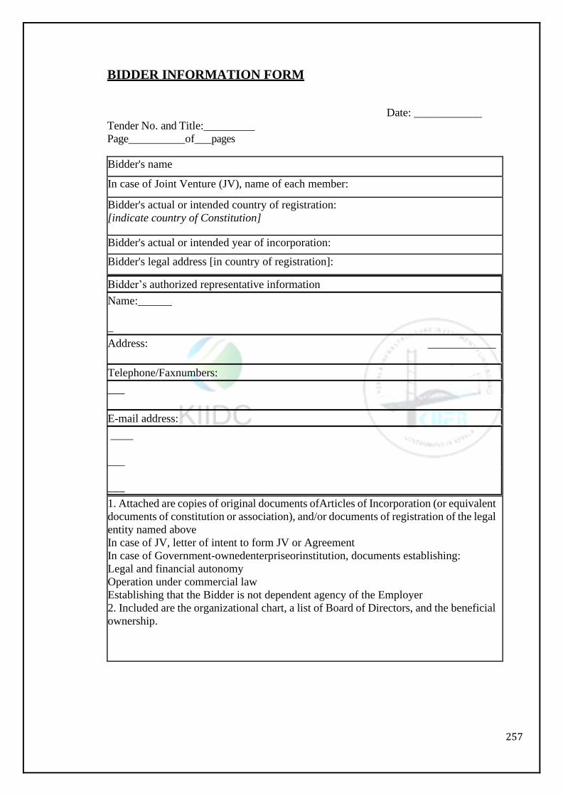
257
BIDDER INFORMATION FORM
Date: ____________
Tender No. and Title:_________
Page__________of___pages
Bidder's name
In case of Joint Venture (JV), name of each member:
Bidder's actual or intended country of registration:
[indicate country of Constitution]
Bidder's actual or intended year of incorporation:
Bidder's legal address [in country of registration]:
Bidder’s authorized representative information
Name:______
_
Address: ____________
Telephone/Faxnumbers:
___
E-mail address:
____
___
___
1. Attached are copies of original documents ofArticles of Incorporation (or equivalent
documents of constitution or association), and/or documents of registration of the legal
entity named above
In case of JV, letter of intent to form JV or Agreement
In case of Government-ownedenterpriseorinstitution, documents establishing:
Legal and financial autonomy
Operation under commercial law
Establishing that the Bidder is not dependent agency of the Employer
2. Included are the organizational chart, a list of Board of Directors, and the beneficial
ownership.
258
Form of Bid-Securing Declaration Date: [insert date (as day, month and year)]
Bid No.: [insert number of bidding process]
Alternative No.: [insert identification No if this is a Bid for an alternative]
To: [insert complete name of Employer]
We, the undersigned, declare that:
We understand that, according to your conditions, bids must be supported by a Bid-Securing
Declaration.
We accept that we will automatically be suspended from being eligible for bidding in any
contract with the entity that invited Bids for the period of time of [insert number of months
or years] starting on [insert date], if we are in breach of our obligation(s) under the bid
conditions, because we:
Have withdrawn our Bid during the period of bid validity specified in the LetterofBid; or
having been notified of the acceptance of our Bid by the Employer during the period of bid
validity, (i) fail or refuse to execute the Contract, if required, or (ii) fail or refuse to furnish
the Performance Security, in accordance with the Instructions to Tenderers.
We understand this Bid-Securing Declaration shall expire if we are not the successful Bidder,
upon the earlier of (i) our receipt of your notification to us of the name of the successful
Bidder; or (ii) twenty-eight days after the expiration of our Bid.
Name of the Bidder*
[insert complete name of person signing the Bid]
Name of the person duly authorized to sign the Bid on behalf of the Bidder ** [insert
complete name of person duly authorized to sign the Bid]
Title of the person signing the Bid [insert complete title of the person signing the
Bid]
Signature of the person named above
[insert signature of person whose name and capacity are shown above]
Date signed [insert date of signing] day of [insert month], [insert year]
*: In the case of the Bid submitted by joint venture specify the name of the Joint
Venture as Bidder
**: Person signing the Bid shall have the power of attorney given by the Bidder to
be attached with the Bid [Note: In case of a Joint Venture, the Bid-Securing
Declaration must be in the name of all members to the Joint Venture that submits the
bid.]

259
Section XI: Bid Statement
260
SECTION – XI
Bid Statement
Table of Forms
Bidder’s Qualification
Statement I: Details of Civil Engineering Works executed during the Last Five (5)
Financial Years onthe Tenderer’s Name
Statement II: Details of Similar Works (i.e. pipe conduit/ aqueduct, siphon, tunnel,
lift irrigation, canal etc).Completed as Prime Contractor (In the Same Name)
DuringtheLast Five (5) FinancialYears
Signature of theTenderer
Statement III
Quantities of works executed in Statement II: Details of Similar Works (i.e. pipe
conduit/ aqueduct, siphon, tunnel, lift irrigation, canal etc). etcasprimecontractor (in
the same name)duringthelast five financial years
Statement IV
Details of Existing Commitments i.e., Works on hand and works for which tenders are
submitted
Statement -V
Availability of Critical Equipment
Statement-VI
Availability of Key Personnel
Statement-VII
Litigation History
261
Bidder’s Qualification To establish its qualifications to perform the contract, the Bidder shall provide the information requested in
the corresponding Information Sheets included hereunder

262
Statement I: Details of Civil Engineering Works Executed during the Last Five (5) Financial
Years on the Tenderer’s Name
Bidder’s Name:
Date:________ JointVentureMember’sName:_
Tender No. and Title:__
Page____of__pages
Starting
Year
Ending
Year
Contract Identification Role of
Bidder
Contract name: ____________________
Brief Description of the Works performed by
theBidder:_____________________________ Amount of contract:__
Name of Employer: ______
Address: ______
___
Contract name: ____________________
Brief Description of the Works performed by
theBidder:_____________________________ Amount of contract:__
Name of Employer: ______
Address: ______
Maximum value of Civil Engineering works executed in any one year during the last
(5) Financial years by the Tenderer.
Sl. No. Financial Year Value in Rs. Update to the Price level 2018-
19
1.
2.
Attach certificate(s) issued by the Executive Engineer concerned and counter signed by
Superintending Engineer showing work wise / year wise value of work done in respect of all
the works executed by the Tenderer during last ten years OR
Certificate from Chartered Accountant supported with Annual Balance Sheet tallying with
I.T. Clearance certificate.
Signature of the Tenderer
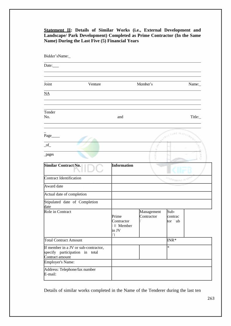
263
Statement II: Details of Similar Works (i.e., External Development and
Landscape/ Park Development) Completed as Prime Contractor (In the Same
Name) During the Last Five (5) Financial Years
Bidder’sName:_
Date:___
Joint Venture Member’s Name:_
NA
Tender
No. and Title:_
_ Page____
_of_
_pages
Similar Contract No. Information
Contract Identification
Award date
Actual date of completion
Stipulated date of Completion
date
Role in Contract
Prime
Contractor
Member
in JV
Management
Contractor
Sub-
contrac
tor ub
Total Contract Amount INR*
If member in a JV or sub-contractor,
specify participation in total
Contract amount
*
Employer's Name:
Address: Telephone/fax number
E-mail:
Details of similar works completed in the Name of the Tenderer during the last ten

264
financial years.
Sl. No Name of the
work
Address of Agt.
Concluding Authority
Agreement No.
& dated.
Value of
Contract
1 2 3 4 5
Stipulated
period of
completion
Actual
date of
completi
on
Value of work had done year wise during the
last ‘Five’ years.
Total value of
work done.
1st
Year
2nd
Year
3rd
Year
4th
Year
5thYear
6
7
9
10
11
12
13
14
Attach certificates issued by the Executive Engineer concerned and countersigned by the
Superintending Engineer showing work wise / year wise value of work done and date of
completion.
Signature of the Tenderer
Details ofSimilarWorks(i.e., External Development and Landscape/ Park
Development) Completed as Prime Contractor (In the Same Name) During the Last
Five (5) Financial Years (cont’d)
Similar Contract No. Information
Description of the similarity
1. Amount
2.Physicalsizeofrequiredworksitems
3. Complexity
4. Methods/Technology
5. Construction rate for key activities
6. Other Characteristics
Signature of the Tenderer
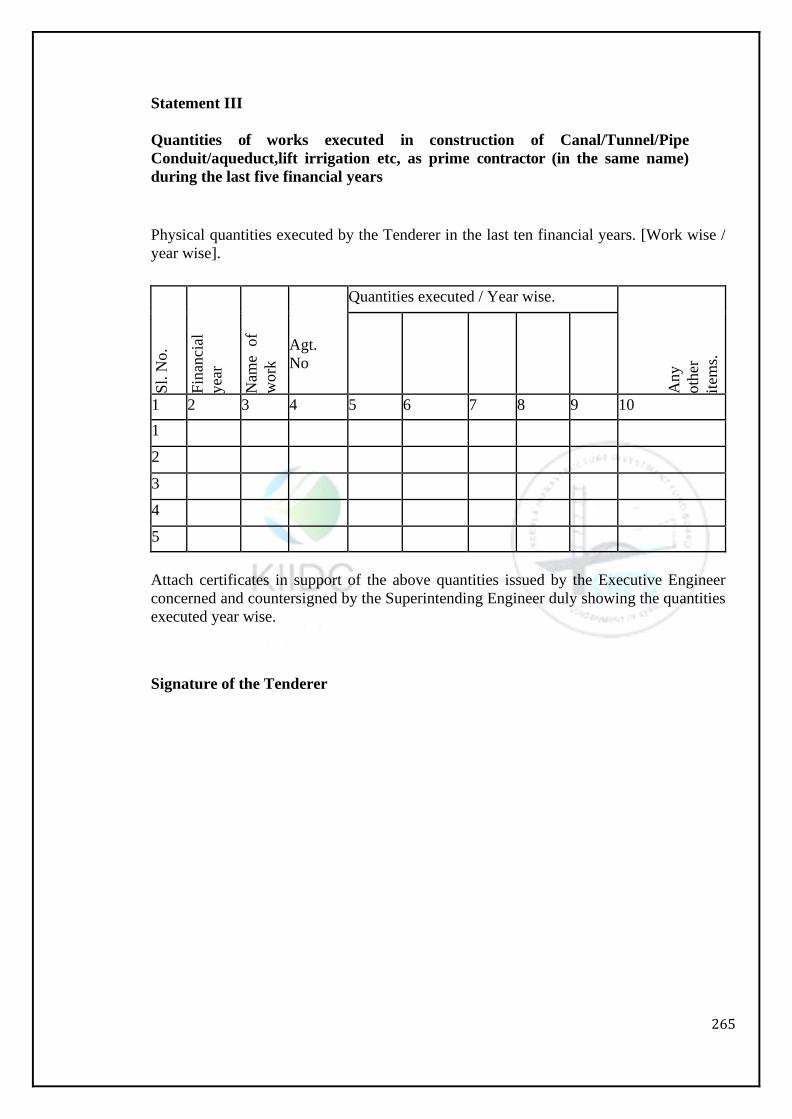
265
Statement III
Quantities of works executed in construction of Canal/Tunnel/Pipe
Conduit/aqueduct,lift irrigation etc, as prime contractor (in the same name)
during the last five financial years
Physical quantities executed by the Tenderer in the last ten financial years. [Work wise /
year wise].
Sl.
No.
Fin
anci
al
yea
r
Nam
e of
work
Agt.
No
Quantities executed / Year wise.
Any
oth
er
item
s.
1 2 3 4 5 6 7 8 9 10
1
2
3
4
5
Attach certificates in support of the above quantities issued by the Executive Engineer
concerned and countersigned by the Superintending Engineer duly showing the quantities
executed year wise.
Signature of the Tenderer
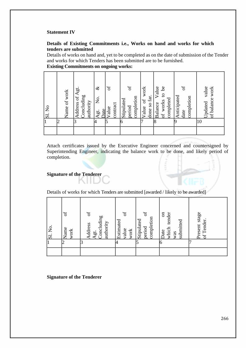
266
Statement IV
Details of Existing Commitments i.e., Works on hand and works for which
tenders are submitted
Details of works on hand and, yet to be completed as on the date of submission of the Tender
and works for which Tenders has been submitted are to be furnished.
Existing Commitments on ongoing works:
Sl.
No
Nam
e of
wo
rk
Addre
ss o
f A
gt.
Concl
udin
g
auth
ori
ty
Agt.
N
o.
&
Dat
e V
alue
of
contr
act
Sti
pula
ted
per
iod
of
com
ple
tion
Val
ue
of
work
done
so f
ar.
Bal
ance
V
alue
of
work
s to
be
com
ple
ted
Anti
cipat
ed
dat
e of
com
ple
tion
Updat
ed
val
ue
of
bal
ance
work
1 2 3 4 5 6 7 8 9 10
Attach certificates issued by the Executive Engineer concerned and countersigned by
Superintending Engineer, indicating the balance work to be done, and likely period of
completion.
Signature of the Tenderer
Details of works for which Tenders are submitted [awarded / likely to be awarded]
Sl.
No.
Nam
e of
work
Addre
ss
of
Agt.
Concl
udin
g
auth
ori
ty
Est
imat
ed
val
ue
of
work
Sti
pula
ted
per
iod
of
com
ple
tion
Dat
e on
whic
h te
nder
was
subm
itte
d
Pre
sent
stag
e
of
Ten
der
.
1 2 3 4 5 6 7
Signature of the Tenderer
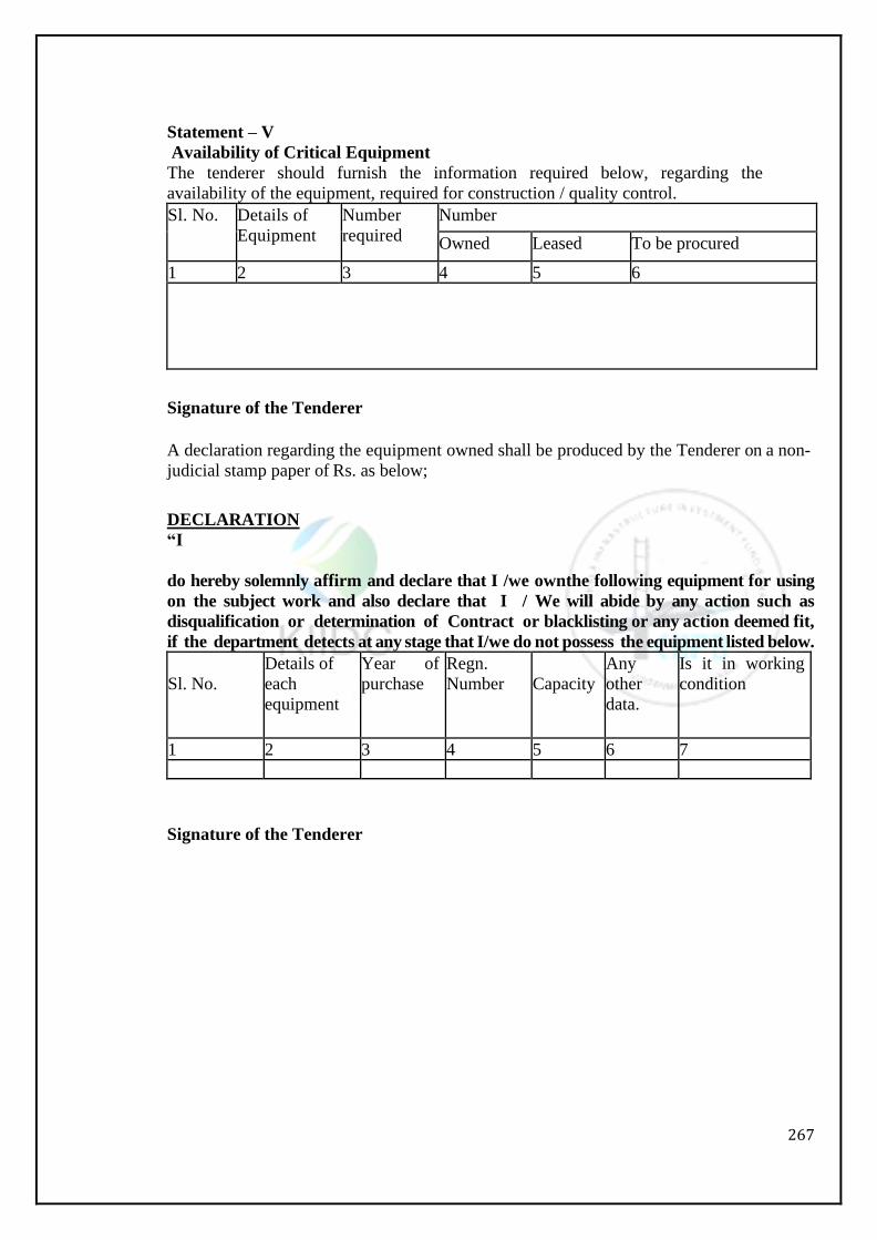
267
Statement – V
Availability of Critical Equipment The tenderer should furnish the information required below, regarding the
availability of the equipment, required for construction / quality control.
Sl. No. Details of
Equipment
Number
required
Number
Owned Leased To be procured
1 2 3 4 5 6
Signature of the Tenderer
A declaration regarding the equipment owned shall be produced by the Tenderer on a non-
judicial stamp paper of Rs. as below;
DECLARATION
“I
do hereby solemnly affirm and declare that I /we ownthe following equipment for using
on the subject work and also declare that I / We will abide by any action such as
disqualification or determination of Contract or blacklisting or any action deemed fit,
if the department detects at any stage that I/we do not possess the equipment listed below.
Sl. No.
Details of
each
equipment
Year of
purchase
Regn.
Number
Capacity
Any
other
data.
Is it in working
condition
1 2 3 4 5 6 7
Signature of the Tenderer

268
Statement - VI
Availability of Key Personnel
Qualification and experience of Key Personnel proposed to be deployed for execution of the
Contract.
Sl. No Name Designation Qualification Total
Experience
Working with the
Tenderer since.
1 2 3 4 5 6
Signature of the Tenderer
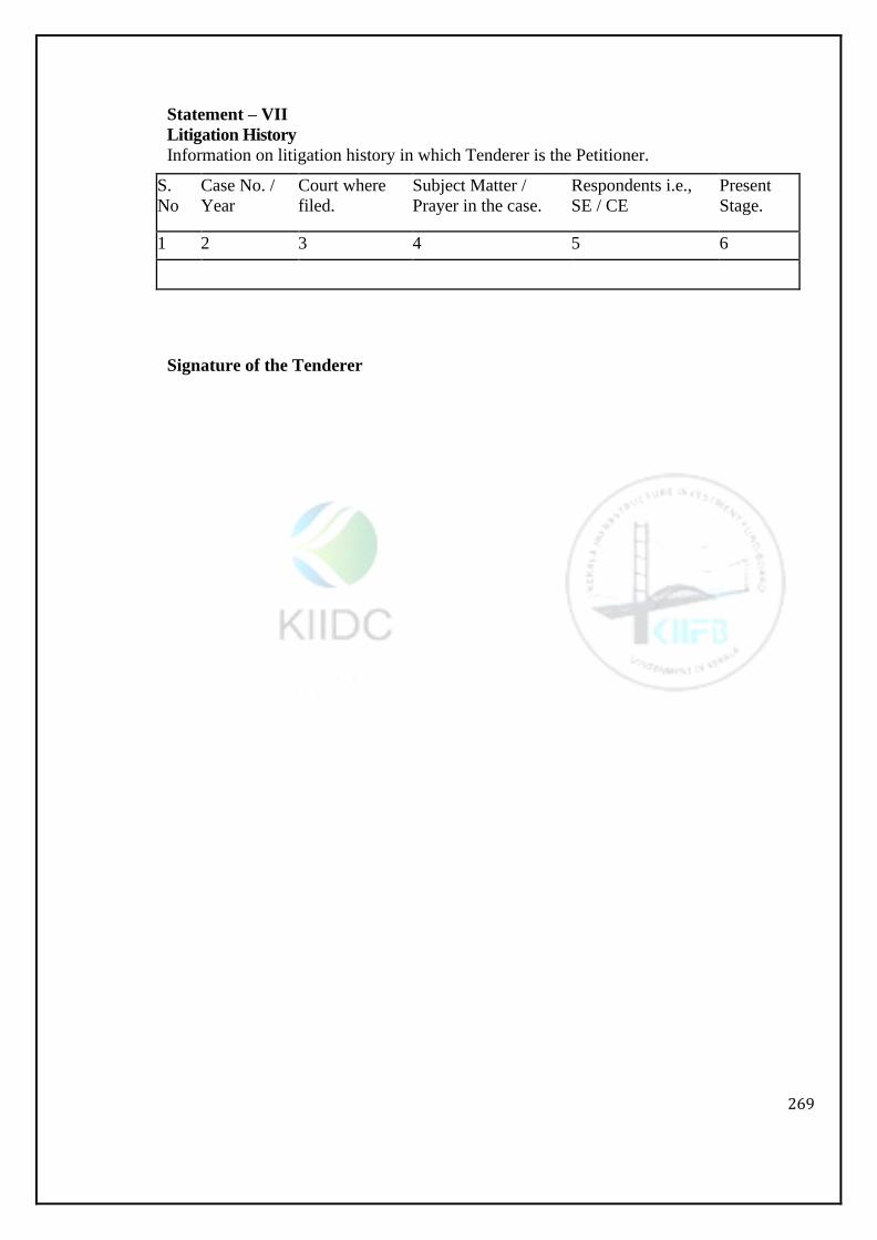
269
Statement – VII
Litigation History
Information on litigation history in which Tenderer is the Petitioner.
S.
No
Case No. /
Year
Court where
filed.
Subject Matter /
Prayer in the case.
Respondents i.e.,
SE / CE
Present
Stage.
1 2 3 4 5 6
Signature of the Tenderer

270
Section XII: Format of Securities

271
SECTION – XII
Format of Securities
PROFORMA
BANK GUARANTEE FORBID SECURITY DEPOSIT
In accordance with the provisions and conditions of Bid Notice for the work of “
”, Sri.
(Name &Address of the Contractor) shall deposit with the Managing Director, Kerala
Irrigation Infrastructure Development Corporation Limited, (a bank guarantee to guarantee
his proper and faithful Performance under the said contract an amount of (Amount of
Guarantee) (in words)
We, the
(Bank or Financial Institution) as requested by the contractor, agree unconditionally and
irrevocably to guarantee as primary obligatory and as surety merely, the payment to the
Managing Director, Kerala Irrigation Infrastructure Development Corporation Limited, on
his demand without what so ever right of objection on our part and without his first claim to
the Executive Engineer,……….Division, for recovery of the whole or part of the Bid
Security from the contractor under the contract.
We further agree to change add to or other modifications of the forms of the contract or of
works to be performed there under or of any of the contract document which may be made
between the Managing Director, Kerala Irrigation Infrastructure Development Corporation
Limited, and the contractor shall in any way release us from any liability under this guarantee
and we here by waive notice of any such change, addition or modification.
THE CONDITIONS of this obligation are: -
If after Bid opening the tenderer withdraws or modifies his Bid during the period of bid
validity specified in the Form of Tender.
If the Tenderer having been notified of the acceptance of his bid by the Department during
the period of validity.
Fails or refuses to execute the Form of Agreement in accordance with the Instructions to
Tenderers, if required; or
Fails or refuses to furnish the balance Bid Security and additional performance Security in
accordance with the instructions of Tenderers.
We undertake to pay to the Department up to the above amount upon receipt of his first
written demand, without the Department having to substantiate his demand, provided that
in his demand the Department will note the amount claimed by him is due to him owning
to the occurrence of one or both of the two conditions, specifying the occurred condition or
conditions.
This Guarantee will remain in force up to and including the date**
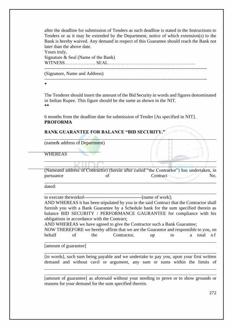
272
after the deadline for submission of Tenders as such deadline is stated in the Instructions to
Tenders or as it may be extended by the Department, notice of which extension(s) to the
Bank is hereby waived. Any demand in respect of this Guarantee should reach the Bank not
later than the above date.
Yours truly,
Signature & Seal (Name of the Bank)
WITNESS……………….. SEAL………………………………………………..
--------------------------------------------------------------------------------------------------------
(Signature, Name and Address)
--------------------------------------------------------------------------------------------------------
*
The Tenderer should insert the amount of the Bid Security in words and figures denominated
in Indian Rupee. This figure should be the same as shown in the NIT.
**
6 months from the deadline date for submission of Tender [As specified in NIT].
PROFORMA
BANK GUARANTEE FOR BALANCE “BID SECURITY.”
(name& address of Department)
WHEREAS
(Nameand address of Contractor) (herein after called “the Contractor”) has undertaken, in
pursuance of Contract No.
dated:
to execute theworkof---------------------------------------[name of work];
AND WHEREAS it has been stipulated by you in the said Contract that the Contractor shall
furnish you with a Bank Guarantee by a Schedule bank for the sum specified therein as
balance BID SECURITY / PERFORMANCE GAURANTEE for compliance with his
obligations in accordance with the Contract;
AND WHEREAS we have agreed to give the Contractor such a Bank Guarantee;
NOW THEREFORE we hereby affirm that we are the Guarantor and responsible to you, on
behalf of the Contractor, up to a total o f
[amount of guarantee]
[in words], such sum being payable and we undertake to pay you, upon your first written
demand and without cavil or argument, any sum or sums within the limits of
[amount of guarantee] as aforesaid without your needing to prove or to show grounds or
reasons for your demand for the sum specified therein.
273
We hereby waive the necessity of your demanding the said debt from the Contractor before
presenting us with the demand.
We further agree that no change or addition to or other modification of the terms of the
Contract or of the Works to be performed there under or of any of the contract documents
which may be made between you and the Contractor shall in anyway release us from any
liability under this guarantee, and we hereby waive notice of any such change, addition or
modification. This guarantee shall be valid up to
i.e., until 28 days from the date of
expiry of the Defects Liability period.
Signature & seal of the Guarantor
Name of Bank
Address
Date
274
PROFORMA
BANK GUARANTEE FOR ADDITIONAL FURTHER PERFORMANCE
GAURANTEE
(Name and address ofDepartment)
WHEREAS
(name and address of Contractor) (hereinafter called “the Contractor”) has undertaken, in
pursuanceofContract No.
dated:
toexecute
[ name of Contract and brief description of works] (herein after called “the Contractor”);
AND WHEREAS it has been stipulated by you in the said Contract that the Contractor shall
furnish you with a Bank Guarantee by a Schedule bank for the sum specified therein as
Additional further Security bank guarantee for compliance with his obligations in
accordance with the Contract;
AND WHEREAS we have agreed to give the Contractor such a Bank Guarantee;
NOW THEREFORE we hereby affirm that we are the Guarantor and responsible to you, on
behalf of the Contractor, up to a total of Rs.
[Amount of guarantee]
[in words], such sum being payable and we undertake to pay you, upon your first written
demand and without cavil or argument, any sum or sums within the limits of
[amount of guarantee] as aforesaid without your needing to prove or to show grounds or
reasons for your demand for the sum specified therein.
We hereby waive the necessity of your demanding the said debt from the Contractor before
presenting us with the demand.
We further agree that no change or addition to or other modification of the terms of the
Contract or of the Works to be performed there under or of any of the contract documents
which may be made between you and the Contractor shall in any way release us from any
liability under this guarantee, and we hereby waive notice of any such change, addition or
modification.
This guarantee shall be valid up to and until 28 days from the date completion.
Signature & seal of the Guarantor
Name of Bank
275
Address
Date
PROFORMA
BANK GUARANTEE FOR MOBILISATION ADVANCE
(name & Address of Agreement Authority)
Sub:-
(name of the work)
Gentlemen:
In accordance with the provisions of the Conditions of Contract, Mobilization advance for
the above-mentioned Contract,
[Name and address of Contractor]
(herein after called “the Contractor”) shall deposit with -----------------------[name
ofDepartment] a bank guarantee to guaranteehisproper and faithful performance under the
said Contract for an amount of Rs. ------------------------[Amount of guarantee]1
(In words).
We, the
[bank], as instructed by the Contractor, agree unconditionally and irrevocably toguaranteeas
primary obligator and not as Surety merely, the payment to
[name of Department] on his first demand without whatsoever right of objection on our part
and without his first claim to the Contractor, for the amount not exceeding (amount of
guarantee)3 __________________________(In words).
We further agree that no change or addition to or other modification of the terms of the
Contract or of works to be performed there under or of any of the Contractor documents
which may bemadebetween
[name of Department] and the Contractor, shall in any way release us from any liability
under this guarantee, and we hereby waive notice of any such change, addition or
modification.
This guarantee shall remain valid andin full effect from the date of the advance payment
under the Contract until

276
[name of Department] receives full repayment of the same amount from the Contractor.
Yours truly,
Signature and seal:
Name of Bank/Financial Institution:
Address:
Date:
1 An amount shall be inserted by the bank representing the amount of the Advance Payment
and denominated in Indian Rupees.
277
AFFIDAVIT
I/We have submitted a bank guarantee for the work
(Name of work)
Agreement
No…………………………………………………………………………………dated……
…………………………………………
………. from
(Name of the Bank with full address).
To the General Manager, KIIDC, -------------
(Name of Division)
with a view seek exemption from payment of Security deposit/performance guarantee in
cash. This bank guarantee expires on…………………………………………………
I/We undertake to keep the validity of the bank guarantee intact by getting it extended for
time to time at my/our own initiative up to a period of
months after the recorded date of completion of the work or as directed by the Employer.
I/We also indemnify the Government against any losses arising out of non-encashment of
back guarantee, if any.
Deponent
Signature of Contractor
Note: The affidavit is to be given by the Executant before a first class Magistrate.
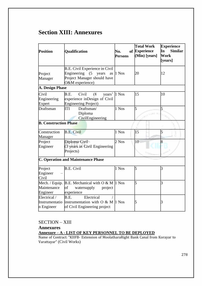
278
Section XIII: Annexures
Position
Qualification
No. of
Persons
Total Work
Experience
(Min) [years]
Experience
In Similar
Work
[years]
Project
Manager
B.E. Civil Experience in Civil
Engineering (5 years as
Project Manager should have
O&M experience)
1 Nos
20
12
A. Design Phase
Civil
Engineering
Expert
B.E. Civil (8 years’
experience inDesign of Civil
Engineering Project)
1 Nos 15 10
Draftsman ITI Draftsman/
Diploma
CivilEngineering
1 Nos 5 5
B. Construction Phase
Construction
Manager
B.E. Civil 1 Nos 15 5
Project
Engineer
Diploma Civil
(3 years in Civil Engineering
Projects)
2 Nos 10 8
C. Operation and Maintenance Phase
Project
Engineer –
Civil
B.E. Civil 1 Nos 5 3
Mech. / Equip.
Maintenance
Engineer
B.E. Mechanical with O & M
of watersupply project
experience
1 Nos 5 3
Electrical /
Instrumentatio
n Engineer
B.E. Electrical /
instrumentation with O & M
of Civil Engineering project
1 Nos
5
3
SECTION – XIII
Annexures Annexure – A - LIST OF KEY PERSONNEL TO BE DEPLOYED Name of Contract: “KIIFB- Extension of MoolatharaRight Bank Canal from Korayar to Varattayar” (Civil Works)
279
Annexure – B - Soil Investigation
Name of Contract “KIIFB- KIIDC - Extension of Moolathara Right Bank Canal
from Korayar to Varattayar” (Civil Works)
Annexure – C – Machinery Required
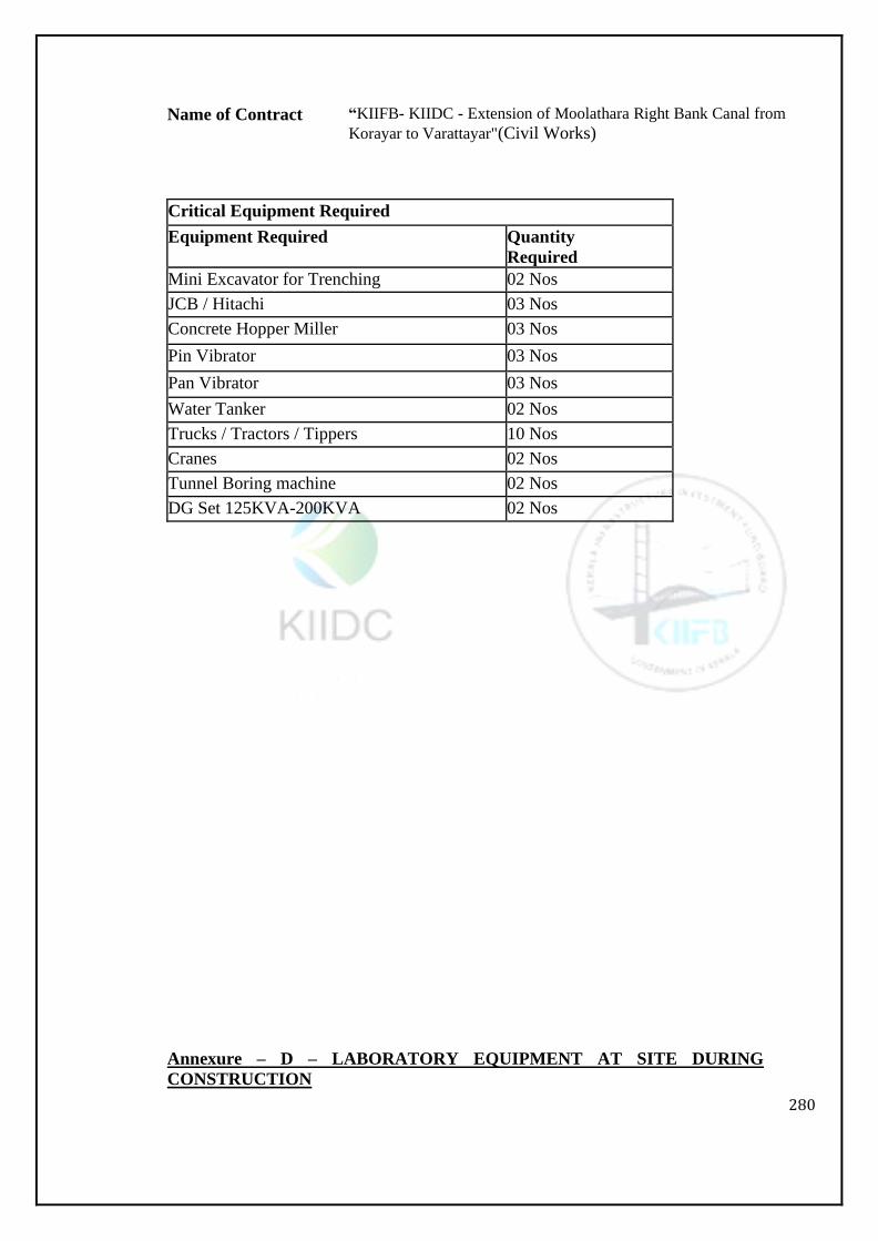
280
Name of Contract “KIIFB- KIIDC - Extension of Moolathara Right Bank Canal from
Korayar to Varattayar"(Civil Works)
Critical Equipment Required
Equipment Required Quantity
Required
Mini Excavator for Trenching 02 Nos
JCB / Hitachi 03 Nos
Concrete Hopper Miller 03 Nos
Pin Vibrator 03 Nos
Pan Vibrator 03 Nos
Water Tanker 02 Nos
Trucks / Tractors / Tippers 10 Nos
Cranes 02 Nos
Tunnel Boring machine 02 Nos
DG Set 125KVA-200KVA 02 Nos
Annexure – D – LABORATORY EQUIPMENT AT SITE DURING
CONSTRUCTION
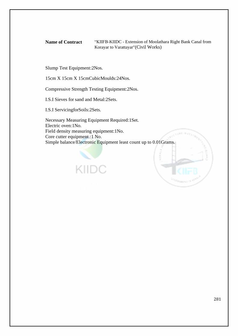
281
Name of Contract “KIIFB-KIIDC - Extension of Moolathara Right Bank Canal from
Korayar to Varattayar"(Civil Works)
Slump Test Equipment:2Nos.
15cm X 15cm X 15cmCubicMoulds:24Nos.
Compressive Strength Testing Equipment:2Nos.
I.S.I Sieves for sand and Metal:2Sets.
I.S.I ServicingforSoils:2Sets.
Necessary Measuring Equipment Required:1Set.
Electric oven:1No.
Field density measuring equipment:1No.
Core cutter equipment.:1 No.
Simple balance/Electronic Equipment least count up to 0.01Grams.
286
Annexure – E – REPORTING REQUIREMENTS
Name of Contract “KIIFB-KIIDC - Extension of Moolathara Right Bank
Canal from Korayar to Varattayar"(Civil Works)
Reports and Records in four sets are to submitted to the Engineer-in-Charge by the EPC
Agency.
(The Reports and Records shall have to be decided according to the nature of the Project and
will be approved by the IBM State Level)

287
Volume 5: Drawings
288
DRAWINGS
DRAWINGS:
The plans enclosed with the tender are liable to the altered during execution of work
as per necessity of site conditions. The premium quoted by the contractor for various
items shall hold good for execution of work even with altered plans.
One set of drawings, on the basis of which actual execution of the work is to proceed
shall be furnished free of cost to the contractor by the Executive Engineer
progressively according to the work program submitted by the contractor and
accepted by the Executive Engineer. Drawings for any particular activity shall be
issued to the contractor at least 30 days in advance of the scheduled date of the start
of the activity. However, no extra claims by the contractor toward any delay in issue
of drawing or issue of any revision / change to the drawings issued earlier shall be
admissible. The Chief Engineer shall intimate the contractor 7 days in advance
regarding any delay to issue of drawings, for any particular stageofworks. If work
gets affected due to delay to issueofdrawings, for any particular stage of work the
contractor shall be granted extension of time in terms of condition of tender notice.
Signed drawings above shall not be deemed to be an order for work unless they
entered in the agreement or schedule of drawings under proper alterations of the
contractor and Executive Engineer or unless they have been sent of the contractor by
the Executive Engineer with a covering letter confirming that the drawing in and
authority for work in contract.
1.0DISCREPANCIES:
In case of discrepancies between documents the following order of procedure shall
apply:-
Between the written description of written dimensions in the drawings and the
corresponding one in the specifications, the latter shall apply.
Figured dimensions shall supersede scaled dimensions. The drawings on a larger
scale shall take precedence over those on a smaller scale.
Drawings issued as construction drawings from time to time shall supersede tender
drawings and alsothecorrespondence drawings previously issued
Note: The contractor should not execute any component of work without
obtaining the working drawings. Any work done without drawings shall be at
the contractor’s responsibility only. Acceptance for such work will be at the
discretion of the Executive Engineer
2.0SECRECY CLAUSE
The drawings and specifications made available to the tenderer shall exclusively be
used on the work and they are retained from passing on each plan to any unauthorized
hand either in parts or in full under the provisions of Section-3 and 5 of the official
secrets Act 1923. Any violation in this regard will entail suitable action under
appropriate clause or official secret Act 1923.
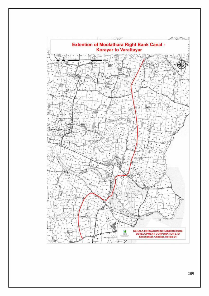
289

290
Volume 6: Bill of Quantities

291
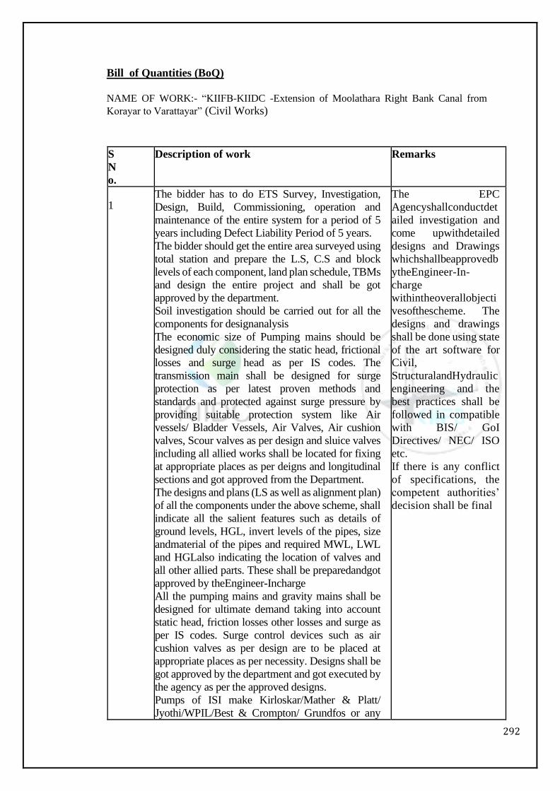
292
Bill of Quantities (BoQ)
NAME OF WORK:- “KIIFB-KIIDC -Extension of Moolathara Right Bank Canal from
Korayar to Varattayar” (Civil Works)
S
N
o.
Description of work Remarks
1 The bidder has to do ETS Survey, Investigation,
Design, Build, Commissioning, operation and
maintenance of the entire system for a period of 5
years including Defect Liability Period of 5 years.
The bidder should get the entire area surveyed using
total station and prepare the L.S, C.S and block
levels of each component, land plan schedule, TBMs
and design the entire project and shall be got
approved by the department.
Soil investigation should be carried out for all the
components for designanalysis
The economic size of Pumping mains should be
designed duly considering the static head, frictional
losses and surge head as per IS codes. The
transmission main shall be designed for surge
protection as per latest proven methods and
standards and protected against surge pressure by
providing suitable protection system like Air
vessels/ Bladder Vessels, Air Valves, Air cushion
valves, Scour valves as per design and sluice valves
including all allied works shall be located for fixing
at appropriate places as per deigns and longitudinal
sections and got approved from the Department.
The designs and plans (LS as well as alignment plan)
of all the components under the above scheme, shall
indicate all the salient features such as details of
ground levels, HGL, invert levels of the pipes, size
andmaterial of the pipes and required MWL, LWL
and HGLalso indicating the location of valves and
all other allied parts. These shall be preparedandgot
approved by theEngineer-Incharge
All the pumping mains and gravity mains shall be
designed for ultimate demand taking into account
static head, friction losses other losses and surge as
per IS codes. Surge control devices such as air
cushion valves as per design are to be placed at
appropriate places as per necessity. Designs shall be
got approved by the department and got executed by
the agency as per the approved designs.
Pumps of ISI make Kirloskar/Mather & Platt/
Jyothi/WPIL/Best & Crompton/ Grundfos or any
The EPC
Agencyshallconductdet
ailed investigation and
come upwithdetailed
designs and Drawings
whichshallbeapprovedb
ytheEngineer-In-
charge
withintheoverallobjecti
vesofthescheme. The
designs and drawings
shall be done using state
of the art software for
Civil,
StructuralandHydraulic
engineering and the
best practices shall be
followed in compatible
with BIS/ GoI
Directives/ NEC/ ISO
etc.
If there is any conflict
of specifications, the
competent authorities’
decision shall be final
293
other reputed make specifically approved by the
department with relevant ISO Certification to draw
raw /clear water with suitable motors of make
Crompton Greaves/
GEC/N.G.E.F/Kirloskar/Jyothi/Seimens/ ABB or
any other reputed make specifically approved by the
Department with shall be provided for prospective
demand as per design and to have minimum
operation and maintenance cost as approved by
Department. The combined efficiency must be not
less than 75% and the pumps should also comply
with Hydraulic Institute Standards. Motors shall be
of high efficiency (Energy) efficient motors
complying with relevant IS codes.
The floor levels of the pumping station and water
level in the sumps are to be fixed for the positive
suction where everpossible.
All the components should be provided with name
boards as directed by the departmental officers.
All the surplus excavated earth of each item is to be
conveyed and leveled as directed by the
departmental officers.
All the Excavated trenches shall be restored to
original condition as per the existing road pavement
structure.
The entire scheme should be completed and
commissioned in 30 months.
The bidder should provide as-built drawings after
successful completion of the scheme (CAPEX
component) and should submit updated as-built
drawings after completion of O&M period (OPEX
component) in consultation with Engineer – in –
Charge and as per directions of the department. The
bidder should handover the scheme after successful
completion ofwork.
All Statutory charges payable to line Departments
like Irrigation, R&B etc. will be borne by the
department except electrical inspectorate Charges.
All approvals required for execution of work shall be
taken up bycontractor.
1.13.4 The bidder has to make arrangements for
traffic Management & Safety Management during
the execution asrequired.
294
Conducting topographical survey, conducting soil
investigation, design and preparation of drawings
and construction/laying pipe line through the
acquired land and keeping the approved hydraulic
particulars (+175.221m at Ch.0.000m to
+170.05m at Ch. 6430m), adopting the latest
technologies in an economical as well as
practically viable way to suit the topography of the
area and , approval of design from the competent
Authority, and implementing the project within a
period of 30 months, testing and commissioning of
the project, etc. complete from Korayar to
Varattayar. (Extension of Moolathara Right
Bank canal for a length of 6430km). The project
should be completed in all aspects, within a period
of 30 months, including the construction of
different hydraulic structures such as conduit,
aqueduct, siphon, tunneletc. to suit the
topography of the area and to feed the entire
ayacut area of the scheme, including the protective
measures to river banks considering the erosion in
the river, sedimentation and siltation abutment of
piers of aqueducts, hydraulic structures such as
inspection chamber, manhole, surplus escape,
controlling regulators, control valves to regulate
the flow as well as sluices to feed ayacut area etc.
6430m Design, Preparing drawings and Providing Lift
Irrigation Schemeto the highest elevated area excluding rock area for an ayacut area of 520 ha with an allowance of 10% in cultivable land including constructing sump at the suitable place, near the entrance area of Tunnel, Pump House, Cistern/Overhead tank at the Highest elevated area, design and installing motor and pump set, including taking into the consideration of the feasibility of conventional/ natural source of Energy, delivery line from pump set to overhead tank (approximate length of 1500m), suction pipe line, distribution pipe, installation of transformer, if found necessary, electrical works, sanction from competent authorities such as Electrical Inspectorate etc.complete. The project should be inclusive of all aspects of works related to testing and commissioning of lift irrigation scheme, including provision for taking delivery of water at intermediate points to feed the ayacut through gravity flow, if found viable etc. complete. The entire project should be completed within the project period of 30
1 unit
295
months.
Repairing and Renovating the existing MRBC from beginning to the end (approximate length of 7000m in total length of 12645m, wherever necessary) so as prevent the seepage of water from the canal, including re-construction of 91 Sluices, providing M S shutters and screw gear arrangement etc.complete including cost and conveyance of materials, labour charges etc. complete.The EPC Contractor should clearly mention the mode and technology that is going to be adopted for repairing/ renovating the existing canal in the bid . The work should be completed in such a way that the water distribution through the existing canal should not be disturbed, during the water distribution period.
1 unit
Improving 14 Nos of Public ponds, within the project area, by removing silt and deepening of 1 to 1.5 m pond and protecting the banks so as to enhance the capacity of tanks, providing feeder channel, pipe line with control valves etc to the tanks from main canal, if possible, etc. complete
14 Nos

296

297