Embed Size (px)
Citation preview
E P I C F i n a l R e p o r t
Program Electric Program Investment Charge (EPIC)
Administrator San Diego Gas & Electric Company
Project Number EPIC-2, Project 1
Project Name
Modernization of Distribution System and Integration of Distributed Generation and Storage
Date December 31, 2017

Attribution
This comprehensive final report documents the work done in Electric Program Investment Charge (EPIC)
2, Project 1. The project team that contributed to the project definition, execution, and reporting included
the following individuals, listed alphabetically by last name:
San Diego Gas & Electric (SDG&E)
Hamid Daneshjoo
Frank Goodman
Molham Kayali
Zoltan Kertay
Iman Mazhari
Alfonso Orozco
Kirsten Petersen
Prajwal Raval
Marvin Zavala-Iraheta
POWER Engineers, Inc.
Matt Cabral
Jason Clack
Chris Dyer
Jared Eby
Aaron Findley
Jake Groat
Ian Higginson
John Kumm
Rick Liposchak
Chin Mou
Matt Phillips
Phil Ricker
Saurabh Shah
Samantha Strasser
Joe White
COMPREHENSIVE FINAL REPORT
i
EXECUTIVE SUMMARY This EPIC project was entitled Modernization of Distribution System and Integration of Distributed
Generation and Storage and is identified as EPIC-2, Project 1 in SDG&E’s EPIC-2 application
approved by the California Public Utilities Commission (CPUC). The objective of the project was to
demonstrate distribution system infrastructure modernization solutions, including advances in
distribution system design to enable use of new technologies, such as power electronic components,
new protection systems, and distributed generation and storage technologies.
The chosen priority for focus of this project was to perform a pre-commercial demonstration in a
laboratory of the International Electrotechnical Commission (IEC) 61850 standard, with specific
emphasis on generic object-oriented substation event (GOOSE) and sampled value (SV) messages.
The demonstration work compared the results to current protective relay practice and performance.
This project also examined the pros and cons of IEC 61850, investigated vendor interoperability
issues, and recommendations on commercial adoption.
Summary of Key Findings and Conclusions
When compared to legacy relay systems, the test system’s protective trip times were improved with
IEC 61850. No degradation in fault identification performance or signal fidelity was noted with the
use of SVs, and all relays were correctly restrained for out-of-zone faults. No failure to trip was
noted during fault simulations when the relays properly subscribed to SV signals from the various
merging units (MUs). The results demonstrated that an IEC 61850 process bus protection and control
(P&C) scheme should be at least as reliable and secure, if not more so, than the existing hardwired
P&C scheme. Although the initial costs of this P&C scheme may be higher, it is anticipated that the
on-going costs will be reduced over a hardwired implementation, and access to corporate and other
enterprise-level data will be improved.
The use of IEC 61850 SV did not impact relay performance, as compared to a direct hardwired
solution, as long as the process bus networks were correctly designed and utilized managed switches
for media access control (MAC) to address filtering as necessary. All use cases were able to be
implemented with the IEC 61850 process bus. The technology is now at a point where it could be
applied to utility protection applications, assuming careful attention to equipment selection for
compatibility.
The project was focused on interoperability and protection system performance. The interoperability
determination was positive. Although interoperability was not achieved with all of the devices,
enough interoperability was achieved to allow for performing all of the protection test cases
identified. Performance of the protection relays using an IEC 61850 P&C scheme was verified to
equal or exceed the performance benchmarks set by the project team.
IEC 61850 process bus technology has progressed to the point where it may be implemented by using
equipment from different manufacturers, but the user can initially expect to spend a significant
amount of time configuring an application when several different manufacturers’ equipment are
included, mainly to get them all to communicate (subscribe) correctly. After completion of this task,
relay protection settings were straightforward. The design of a fully IEC 61850 compliant substation
will differ greatly from the current hardwired state of the art, which will impact design standards that
may currently be in place. To ensure success, issues such as maintenance, testing, and training must
COMPREHENSIVE FINAL REPORT
ii
also be addressed before embarking on commercial adoption and implementation of an IEC 61850
project.
Overall, the results from this project were very promising. Compared to just a couple years ago,
implementing GOOSE and manufacturing message specification (MMS) messaging was found to be
much easier between relays, and between relays and MUs. SV based P&C was found to be
equivalent or better than legacy solutions for the identified use cases. In addition, only a small
number of SV interoperability problems were identified. It was anticipated that interoperability will
greatly improve in the near term as the IEC 61850 standards, P&C equipment, and software tools
mature. Interoperability will be crucial for system maintainability, ensuring that failed components
may be replaced with newer equipment without comprising system operation.
Recommendations and Next Steps
The project team recommends that SDG&E continue to explore commercial adoption of IEC 61850
applications within its substations. The project findings and conclusions show that, although care is
required in the selection of products, the currently available merging units and relays are sufficiently
mature to support interoperability between vendors. In addition, the protection performance of the
test system is equivalent to hardwired legacy P&C systems.
The project team further recommends that an SDG&E communications laboratory be developed to
support future work and training. This laboratory would include the capability to mock-up future
substation communications infrastructure to validate their performance before actual deployment in
substations. Although this laboratory would have a focus on IEC 61850, it would also support testing
of other communications technologies and standards.
With the completion of the future work items, the project team recommends that pilot projects be
initiated to gain experience with IEC 61850. Potential pilot projects could include a GOOSE based
12 kilovolt (kV) capacitor control scheme using existing installed hardware, or a three breaker 69 kV
P&C scheme. These pilot projects could be precursors towards development of a larger project to test
the technology in an actual substation. A pilot project will serve as the basis for developing new
standards for station drawings, relay settings, supervisory control and data acquisition (SCADA) and
communication configurations. A substation located in close proximity to a maintenance center
would be an ideal candidate for this type of pilot project because of the training opportunities it
provides.
An IEC 61850 design implementation will differ greatly from current hardwired state of the art, and
issues such as maintenance, testing and training, must be addressed while embarking on the first
implementation of this technology.
SDG&E should make the results of this EPIC project available to the various standards bodies
associated with IEC 61850 – especially IEC Technical Committee 57, Working Group 10.
The project did not explore networking architecture solutions as they were applied to substations.
Network architecture, redundancy and security are essential factors in substation communications
which should be considered when designing an IEC 61850 implementation. For an actual substation
implementation, considerable thought should be given to network design and optimization.
COMPREHENSIVE FINAL REPORT
iii
TABLE OF CONTENTS
EXECUTIVE SUMMARY .................................................................................................................. I
SUMMARY OF KEY FINDINGS AND CONCLUSIONS .............................................................................. I RECOMMENDATIONS AND NEXT STEPS .............................................................................................. II
1. GLOSSARY .................................................................................................................................. 1
2. INTRODUCTION ........................................................................................................................ 4
3. IEC 61850 OVERVIEW AND ISSUES ...................................................................................... 6
FOCUS ................................................................................................................................................. 6 IEC 61850 ........................................................................................................................................... 6 ADVANTAGES OF IEC 61850 .............................................................................................................. 6 UNITED STATES ADOPTION OF IEC 61850 ......................................................................................... 7 MAJOR THRUSTS OF PROJECT WORK ................................................................................................. 8 KNOWLEDGE APPLICATION ................................................................................................................ 8
4. OVERVIEW OF APPROACH ................................................................................................... 9
PRE-COMMERCIAL DEMONSTRATION ................................................................................................ 9 ADDITIONAL DEMONSTRATION AT INTEGRATED TEST FACILITY (ITF) .......................................... 10 TECHNOLOGY TRANSFER ACTIVITIES DURING THE PROJECT .......................................................... 10
Classroom Training ...................................................................................................................... 10 Software Training ......................................................................................................................... 10 Pre-commercial Demonstration Training ..................................................................................... 10 Hands-On Training with Vendors ................................................................................................ 10
5. BASELINE ASSESSMENT ...................................................................................................... 11
6. TEST CASES .............................................................................................................................. 13
TEST CASE #1 – BREAKER FAILURE PROTECTION (50BF) ............................................................... 13 TEST CASE #2 – LINE DIFFERENTIAL PROTECTION (87L) ................................................................ 14 TEST CASE #3 – LINE DISTANCE AND DIRECTIONAL OVERCURRENT PROTECTION (21 & 50/51) ... 14 TEST CASE #4 – HIGH VOLTAGE (HV) BUS OVERCURRENT DIFFERENTIAL PROTECTION (87B-
50/51)................................................................................................................................................ 15 TEST CASE #5 – HV BUS RESTRAINED CURRENT DIFFERENTIAL PROTECTION (87B) .................... 15 TEST CASE #6 – HV BUS HIGH IMPEDANCE (HIZ) DIFFERENTIAL PROTECTION (87B-HIZ) ........... 16 TEST CASE #7 – TRANSFORMER RESTRAINED CURRENT DIFFERENTIAL PROTECTION (87T) .......... 16 TEST CASE #8 – TRANSFORMER OVERCURRENT PROTECTION (50/51T) ......................................... 17 TEST CASE #9 – 12KV BUS PARTIAL OVERCURRENT DIFFERENTIAL PROTECTION (87B-51P/G) ... 17 TEST CASE #10 – 12KV BUS RESTRAINED CURRENT DIFFERENTIAL PROTECTION (87B) ............... 18 TEST CASE #11 – CAPACITOR AND REACTOR FEEDER OVERCURRENT PROTECTION (50/51) ......... 18 TEST CASE #12 – CAPACITOR BANK UNBALANCE PROTECTION (59N) ........................................... 19 TEST CASE #13 – REACTOR UNBALANCE PROTECTION (51Q) ......................................................... 19 TEST CASE #14 – REACTOR AND CAPACITOR BANK VAR CONTROL AUTOMATION ...................... 20 TEST CASE #15 – LINE FREQUENCY AND VOLTAGE (81, 27, AND 59) ............................................. 20
7. CONCEPT OF OPERATIONS ................................................................................................. 22
PROTECTION AND CONTROL ARCHITECTURE................................................................................... 22 Process Bus ................................................................................................................................... 22
COMPREHENSIVE FINAL REPORT
iv
Station Bus ................................................................................................................................... 23 Time Synchronization .................................................................................................................. 23 Engineering and Maintenance Access .......................................................................................... 23 Information Exchanges ................................................................................................................. 23
CONTROLLABLE DEVICES AND FUNCTIONAL SPECIFICATIONS ....................................................... 23 Capacitor and Reactor Bank Automation ..................................................................................... 23 High Side and Low Side Lockout Relays ..................................................................................... 24 Minimum Local Area Network (LAN) Communication Requirements ....................................... 24 Minimum Wide Area Network (WAN) Communication Requirements ...................................... 25 Cybersecurity Considerations for Switched Networks ................................................................. 25
OPERATIONAL REQUIREMENTS ........................................................................................................ 26
8. TEST SYSTEM SPECIFICATION .......................................................................................... 28
RACK LIMITATIONS .......................................................................................................................... 28 ELECTRICAL ...................................................................................................................................... 28
Voltages ........................................................................................................................................ 28 NETWORKING ................................................................................................................................... 28
Fiber.............................................................................................................................................. 29 Copper .......................................................................................................................................... 29 Network Capabilities .................................................................................................................... 31 Network Security .......................................................................................................................... 31 Test Set Interface .......................................................................................................................... 31 Network Tools .............................................................................................................................. 31 Station Bus ................................................................................................................................... 31 Process Bus ................................................................................................................................... 31 Process Bus #2 .............................................................................................................................. 32
TEST SYSTEM TIME SYNCHRONIZATION .......................................................................................... 32 IEEE 1588 Precision Time Protocol (PTP) .................................................................................. 32 Inter-Range Instrumentation Group (IRIG-B) .............................................................................. 33 1 Pulse per Second (1PPS) ........................................................................................................... 33 Simple Network Time Protocol (SNTP) ...................................................................................... 33
IEC 61850 INFORMATION TRANSFER PROTOCOLS ........................................................................... 33 Manufacturing Message Specification (MMS) ............................................................................ 33 Generic Object Oriented Substation Events (GOOSE) ................................................................ 33 Sampled Value (SV) ..................................................................................................................... 33 GOOSE and SV Data Flow Spreadsheet ...................................................................................... 33 Process Bus Data Flow Diagram .................................................................................................. 34 Station Bus Data Flow Diagram ................................................................................................... 34 Capacitor and Reactor Bank Automation ..................................................................................... 35 High Side (HS) and Low Side (LS) Lockout Relays .................................................................... 35
INTERFACES ...................................................................................................................................... 35 Test Switches ................................................................................................................................ 35
DEVICE REQUIREMENTS ................................................................................................................... 35 Relays ........................................................................................................................................... 35 Process Bus Merging Units (MUs) ............................................................................................... 35 Software ........................................................................................................................................ 36 Ethernet Switch Features .............................................................................................................. 36 Time Clock ................................................................................................................................... 36
COMPREHENSIVE FINAL REPORT
v
Breaker Simulators ....................................................................................................................... 36 RTDS AND COMTRADE ................................................................................................................. 36
RTDS ............................................................................................................................................ 37 RTDS Model ................................................................................................................................ 38 COMTRADE FILES .................................................................................................................... 39 Wetting voltage ............................................................................................................................ 40
INTEGRATED TEST FACILITY (ITF) EVALUATION ............................................................................ 40
9. TEST SYSTEM DESIGN .......................................................................................................... 41
DESIGN PROCESS .............................................................................................................................. 42 MATERIAL IDENTIFICATION AND PROCUREMENT ............................................................................ 44 PRELIMINARY DESIGN PROCESS ....................................................................................................... 45 TEST SYSTEM NETWORK .................................................................................................................. 49 TEST SYSTEM TIME SYNCHRONIZATION .......................................................................................... 50
IEEE 1588 PTP ............................................................................................................................ 51 IRIG-B .......................................................................................................................................... 51 1PPS ............................................................................................................................................. 52 SNTP ............................................................................................................................................ 52
PROCESS BUS MUS ........................................................................................................................... 52 IEC 61850 EDITIONS ........................................................................................................................ 52 DATA FLOWS .................................................................................................................................... 64
GOOSE and Sampled Value Data Flow Spreadsheet .................................................................. 64 PROCESS BUS DATA FLOW DIAGRAM .............................................................................................. 71 STATION BUS DATA FLOW DIAGRAM .............................................................................................. 74 PHASE ONE INITIAL SYSTEM INTEGRATION AND CONFIGURATION ................................................. 76
Vendor V2 Equipment .................................................................................................................. 76 Vendor V3 Equipment .................................................................................................................. 78 Vendor V6 Equipment .................................................................................................................. 78 Vendor V7 Equipment .................................................................................................................. 79 Test Equipment ............................................................................................................................. 80 Network Equipment...................................................................................................................... 80
PHASE TWO SYSTEM INTEGRATION AND TESTING RESULTS ........................................................... 80 Vendor V3 Equipment .................................................................................................................. 80 Vendor V7 Equipment .................................................................................................................. 81 Vendor V6 Equipment .................................................................................................................. 81 Capacitor and Reactor Bank Control System ............................................................................... 81 Vendor V1 Equipment .................................................................................................................. 81 Vendor V2 Equipment .................................................................................................................. 82
PHASE THREE SYSTEM INTEGRATION AND TESTING RESULTS .......................................................... 82 V1M5 PDU Length Problem ........................................................................................................ 84 File Import Problem into V1M8 Tool .......................................................................................... 87 Time Synchronization to the V1M5 ............................................................................................. 91 Neutral Current and Voltage Calculation Problem ....................................................................... 91
PHASE FOUR SYSTEM INTEGRATION AND TESTING RESULTS .......................................................... 91 Denial of Service to V2M1, V2M2, V2M3, V2M4 ..................................................................... 91 V7M2 Analog Data Set Error ....................................................................................................... 92 V2M1, V2M2, V2M3, and V2M4 “Fast GOOSE” and Unsubscribing ....................................... 92 V2M1 Internal Blocking ............................................................................................................... 93
COMPREHENSIVE FINAL REPORT
vi
Miscellaneous Items ..................................................................................................................... 93 Distance Protection Trips ............................................................................................................. 93
PHASE FIVE SYSTEM INTEGRATION AND TESTING RESULTS ........................................................... 94 DEVELOPED ALGORITHMS ............................................................................................................... 95
Capacitor and Reactor Bank ......................................................................................................... 95 Bus and Transformer “Virtual” Lockout Relays .......................................................................... 96
INTEROPERABILITY ........................................................................................................................... 98
10. TEST PROCEDURES ......................................................................................................... 100
TEST CASE #1 – BREAKER FAILURE PROTECTION (50BF) ............................................................. 100 Relay Test Setup Conditions and Requirements ........................................................................ 100 Test Case Voltage and Current Injection from Relay Test Sets ................................................. 101
TEST CASE #2 – LINE DIFFERENTIAL PROTECTION (87L) .............................................................. 101 Relay Test Setup Conditions and Requirements ........................................................................ 101 Test case voltage and current injection from relay test sets ....................................................... 102
TEST CASE #3 – LINE DISTANCE AND DIRECTIONAL OVERCURRENT PROTECTION (21 AND 50/51)
........................................................................................................................................................ 104 Relay Test Setup Conditions and Requirements ........................................................................ 104 Test Case Voltage and Current Injection from Relay Test Sets ................................................. 104
TEST CASE #4 – HIGH VOLTAGE (HV) BUS OVERCURRENT DIFFERENTIAL PROTECTION (87B-
50/51).............................................................................................................................................. 107 Relay Test Setup Conditions and Requirements ........................................................................ 107 Test Case Voltage and Current Injection from Relay Test Sets ................................................. 108
TEST CASE #5 – HV BUS RESTRAINED CURRENT DIFFERENTIAL PROTECTION (87B) .................. 109 Relay Test Setup Conditions and Requirements ........................................................................ 109 Test Case Voltage and Current Injection from Relay Test Sets ................................................. 110
TEST CASE #6 – HV BUS HIGH IMPEDANCE DIFFERENTIAL PROTECTION (87B-HIZ) ................... 111 Relay Test Setup Conditions and Requirements ........................................................................ 111 Test Case Voltage and Current Injection from Relay Test Sets ................................................. 111
TEST CASE #7 – TRANSFORMER RESTRAINED CURRENT DIFFERENTIAL PROTECTION (87T) ....... 112 Relay Test Setup Conditions and Requirements ........................................................................ 112 Test Case Voltage and Current Injection from Relay Test Sets ................................................. 112
TEST CASE #8 – TRANSFORMER OVERCURRENT PROTECTION (50/51T) ....................................... 114 Relay Test Setup Conditions and Requirements ........................................................................ 114 Test Case Voltage and Current Injection from Relay Test Sets ................................................. 115
TEST CASE #9 – 12 KV BUS PARTIAL OVERCURRENT DIFFERENTIAL PROTECTION (87B-51P/G) 117 Relay Test Setup Conditions and Requirements ........................................................................ 117 Test Case Voltage and Current Injection from Relay Test Sets ................................................. 117
TEST CASE #10 – 12 KV BUS RESTRAINED CURRENT DIFFERENTIAL PROTECTION (87B) ............ 119 Relay Test Setup Conditions and Requirements ........................................................................ 119 Test Case Voltage and Current Injection from Relay Test Sets ................................................. 119
TEST CASE #11 – CAPACITOR AND REACTOR FEEDER OVERCURRENT PROTECTION (50/51) ....... 120 Relay Test Setup Conditions and Requirements ........................................................................ 120 Test Case Voltage and Current Injection from Relay Test Sets ................................................. 121
TEST CASE #12 – CAPACITOR BANK UNBALANCE PROTECTION (59N) ......................................... 122 Relay Test Setup Conditions and Requirements ........................................................................ 122 Test Case Voltage and Current Injection from Relay Test Sets ................................................. 122
TEST CASE #13 – REACTOR UNBALANCE PROTECTION (51Q) ....................................................... 123
COMPREHENSIVE FINAL REPORT
vii
Relay Test Setup Conditions and Requirements ........................................................................ 123 Test Case Voltage and Current Injection from Relay Test Sets ................................................. 123 Test Case Performance Tests ...................................................................................................... 123
TEST CASE #14 – REACTOR AND CAPACITOR BANK VAR CONTROL AUTOMATION .................... 123 Relay Test Setup Conditions and Requirements ........................................................................ 123 Test Case Voltage and Current Injection from Relay Test Sets ................................................. 124
TEST CASE #15 – LINE FREQUENCY AND VOLTAGE (81, 27, AND 59) ........................................... 126 Relay Test Setup Conditions and Requirements ........................................................................ 126 Test Case Voltage and Current Injection from Relay Test Sets ................................................. 126
11. TEST RESULTS AND DATA ANALYSIS........................................................................ 129
MEASUREMENT AND VERIFICATION .............................................................................................. 129 IMPACTS ON EXISTING SUBSTATION AND TRANSMISSION PROTECTION ....................................... 129
Reliability – Protection ............................................................................................................... 129 Reliability – Communications .................................................................................................... 129 Speed of Operations ................................................................................................................... 131
IMPACTS ON EXISTING SUBSTATION SYSTEMS AND EQUIPMENT .................................................. 131 IMPACTS ON SYSTEM OPERATIONS ................................................................................................ 132 MAINTENANCE IMPACTS ................................................................................................................ 132 COSTS ............................................................................................................................................. 132
Estimate Assumptions ................................................................................................................ 132 PROS AND CONS ............................................................................................................................. 135
Pros ............................................................................................................................................. 135 Cons ............................................................................................................................................ 137
MIGRATION PROCESS ..................................................................................................................... 137
12. KEY FINDINGS ................................................................................................................... 139
IEC 61850 IMPLEMENTATION CHALLENGES .................................................................................. 140
13. CONCLUSIONS ................................................................................................................... 142
14. RECOMMENDATIONS ..................................................................................................... 143
FUTURE WORK ................................................................................................................................ 143 Network Optimization ................................................................................................................ 143 Remote Access ........................................................................................................................... 143 Redundancy ................................................................................................................................ 144 SCADA ...................................................................................................................................... 144 SV Implementations ................................................................................................................... 144
15. POST-PROJECT TECHNOLOGY TRANSFER ............................................................. 145
16. METRICS AND VALUE PROPOSITION:
Metrics:
METRICS AND VALUE PROPOSITION:
Metrics:
Value proposition:
REFERENCES ................................................................................................................................. 148
COMPREHENSIVE FINAL REPORT
viii
BIBLIOGRAPHY ............................................................................................................................ 149

COMPREHENSIVE FINAL REPORT
ix
APPENDICES Appendix A - Test Case Data Flow Diagrams ................................................................................... A-1
Appendix B - RTDS Model Diagram ................................................................................................. B-1
Appendix C - Network Layout Diagram ............................................................................................ C-1
Appendix D - 61850 Matrix ............................................................................................................... D-1
Appendix E - Network IP and 61850 Dataflow Spreadsheet ............................................................. E-1
Appendix F - COMTRADE Graphical Analysis ................................................................................ F-1
Appendix G - Operating Times Spreadsheet ...................................................................................... G-1
Appendix H - Observations ................................................................................................................ H-1
COMPREHENSIVE FINAL REPORT
ix
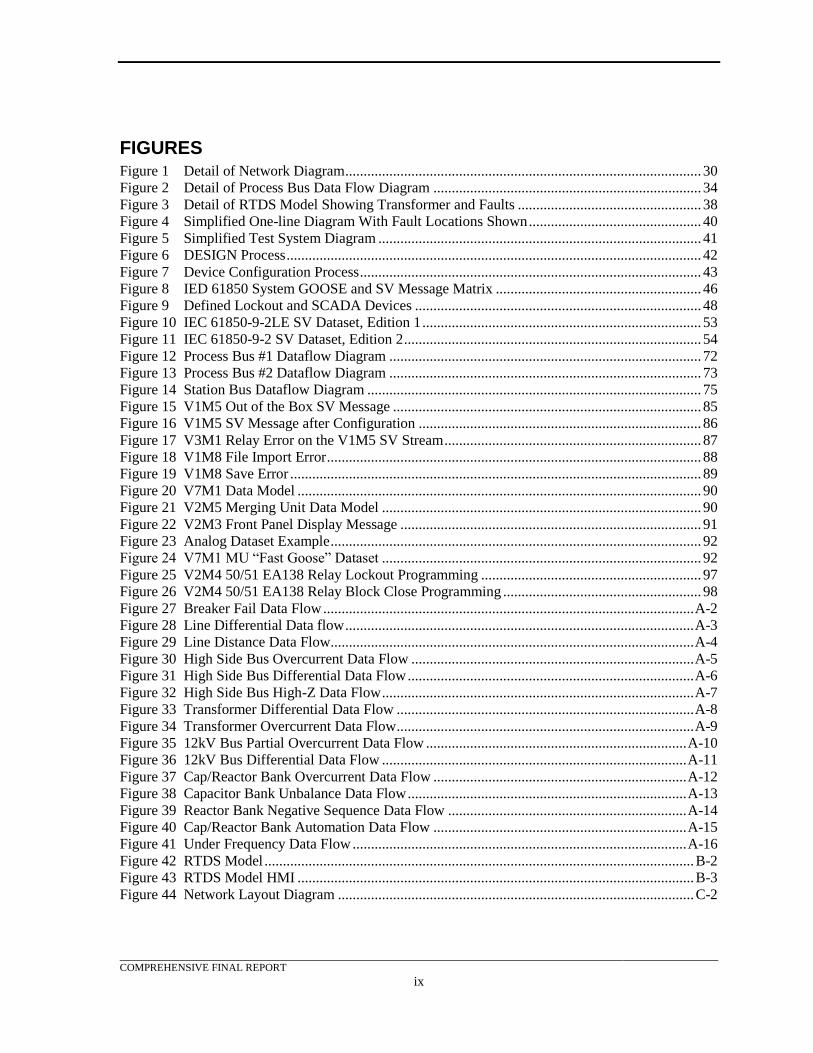
FIGURES Figure 1 Detail of Network Diagram ................................................................................................. 30
Figure 2 Detail of Process Bus Data Flow Diagram ......................................................................... 34
Figure 3 Detail of RTDS Model Showing Transformer and Faults .................................................. 38
Figure 4 Simplified One-line Diagram With Fault Locations Shown ............................................... 40
Figure 5 Simplified Test System Diagram ........................................................................................ 41
Figure 6 DESIGN Process ................................................................................................................. 42
Figure 7 Device Configuration Process ............................................................................................. 43
Figure 8 IED 61850 System GOOSE and SV Message Matrix ........................................................ 46
Figure 9 Defined Lockout and SCADA Devices .............................................................................. 48
Figure 10 IEC 61850-9-2LE SV Dataset, Edition 1 ............................................................................ 53
Figure 11 IEC 61850-9-2 SV Dataset, Edition 2 ................................................................................. 54
Figure 12 Process Bus #1 Dataflow Diagram ..................................................................................... 72
Figure 13 Process Bus #2 Dataflow Diagram ..................................................................................... 73
Figure 14 Station Bus Dataflow Diagram ........................................................................................... 75
Figure 15 V1M5 Out of the Box SV Message .................................................................................... 85
Figure 16 V1M5 SV Message after Configuration ............................................................................. 86
Figure 17 V3M1 Relay Error on the V1M5 SV Stream ...................................................................... 87
Figure 18 V1M8 File Import Error ...................................................................................................... 88
Figure 19 V1M8 Save Error ................................................................................................................ 89
Figure 20 V7M1 Data Model .............................................................................................................. 90
Figure 21 V2M5 Merging Unit Data Model ....................................................................................... 90
Figure 22 V2M3 Front Panel Display Message .................................................................................. 91
Figure 23 Analog Dataset Example ..................................................................................................... 92
Figure 24 V7M1 MU “Fast Goose” Dataset ....................................................................................... 92
Figure 25 V2M4 50/51 EA138 Relay Lockout Programming ............................................................ 97
Figure 26 V2M4 50/51 EA138 Relay Block Close Programming ...................................................... 98
Figure 27 Breaker Fail Data Flow ..................................................................................................... A-2
Figure 28 Line Differential Data flow ............................................................................................... A-3
Figure 29 Line Distance Data Flow ................................................................................................... A-4
Figure 30 High Side Bus Overcurrent Data Flow ............................................................................. A-5
Figure 31 High Side Bus Differential Data Flow .............................................................................. A-6
Figure 32 High Side Bus High-Z Data Flow ..................................................................................... A-7
Figure 33 Transformer Differential Data Flow ................................................................................. A-8
Figure 34 Transformer Overcurrent Data Flow ................................................................................. A-9
Figure 35 12kV Bus Partial Overcurrent Data Flow ....................................................................... A-10
Figure 36 12kV Bus Differential Data Flow ................................................................................... A-11
Figure 37 Cap/Reactor Bank Overcurrent Data Flow ..................................................................... A-12
Figure 38 Capacitor Bank Unbalance Data Flow ............................................................................ A-13
Figure 39 Reactor Bank Negative Sequence Data Flow ................................................................. A-14
Figure 40 Cap/Reactor Bank Automation Data Flow ..................................................................... A-15
Figure 41 Under Frequency Data Flow ........................................................................................... A-16
Figure 42 RTDS Model ..................................................................................................................... B-2
Figure 43 RTDS Model HMI ............................................................................................................ B-3
Figure 44 Network Layout Diagram ................................................................................................. C-2
COMPREHENSIVE FINAL REPORT
1
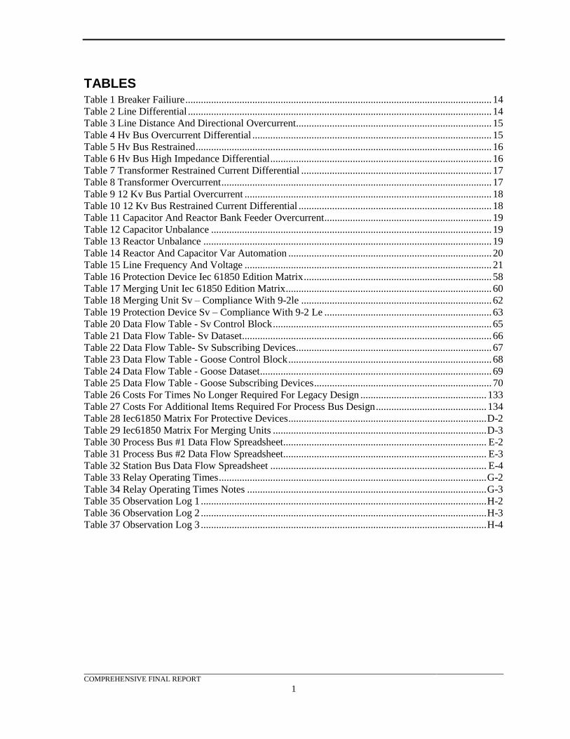
TABLES Table 1 Breaker Failiure ....................................................................................................................... 14
Table 2 Line Differential ...................................................................................................................... 14
Table 3 Line Distance And Directional Overcurrent ............................................................................ 15
Table 4 Hv Bus Overcurrent Differential ............................................................................................. 15
Table 5 Hv Bus Restrained ................................................................................................................... 16
Table 6 Hv Bus High Impedance Differential ...................................................................................... 16
Table 7 Transformer Restrained Current Differential .......................................................................... 17
Table 8 Transformer Overcurrent ......................................................................................................... 17
Table 9 12 Kv Bus Partial Overcurrent ................................................................................................ 18
Table 10 12 Kv Bus Restrained Current Differential ........................................................................... 18
Table 11 Capacitor And Reactor Bank Feeder Overcurrent ................................................................. 19
Table 12 Capacitor Unbalance ............................................................................................................. 19
Table 13 Reactor Unbalance ................................................................................................................ 19
Table 14 Reactor And Capacitor Var Automation ............................................................................... 20
Table 15 Line Frequency And Voltage ................................................................................................ 21
Table 16 Protection Device Iec 61850 Edition Matrix ......................................................................... 58
Table 17 Merging Unit Iec 61850 Edition Matrix ................................................................................ 60
Table 18 Merging Unit Sv – Compliance With 9-2le .......................................................................... 62
Table 19 Protection Device Sv – Compliance With 9-2 Le ................................................................. 63
Table 20 Data Flow Table - Sv Control Block ..................................................................................... 65
Table 21 Data Flow Table- Sv Dataset ................................................................................................. 66
Table 22 Data Flow Table- Sv Subscribing Devices ............................................................................ 67
Table 23 Data Flow Table - Goose Control Block ............................................................................... 68
Table 24 Data Flow Table - Goose Dataset .......................................................................................... 69
Table 25 Data Flow Table - Goose Subscribing Devices ..................................................................... 70
Table 26 Costs For Times No Longer Required For Legacy Design ................................................. 133
Table 27 Costs For Additional Items Required For Process Bus Design ........................................... 134
Table 28 Iec61850 Matrix For Protective Devices ............................................................................. D-2
Table 29 Iec61850 Matrix For Merging Units ................................................................................... D-3
Table 30 Process Bus #1 Data Flow Spreadsheet............................................................................... E-2
Table 31 Process Bus #2 Data Flow Spreadsheet............................................................................... E-3
Table 32 Station Bus Data Flow Spreadsheet .................................................................................... E-4
Table 33 Relay Operating Times ........................................................................................................ G-2
Table 34 Relay Operating Times Notes ............................................................................................. G-3
Table 35 Observation Log 1 ............................................................................................................... H-2
Table 36 Observation Log 2 ............................................................................................................... H-3
Table 37 Observation Log 3 ............................................................................................................... H-4
COMPREHENSIVE FINAL REPORT
1
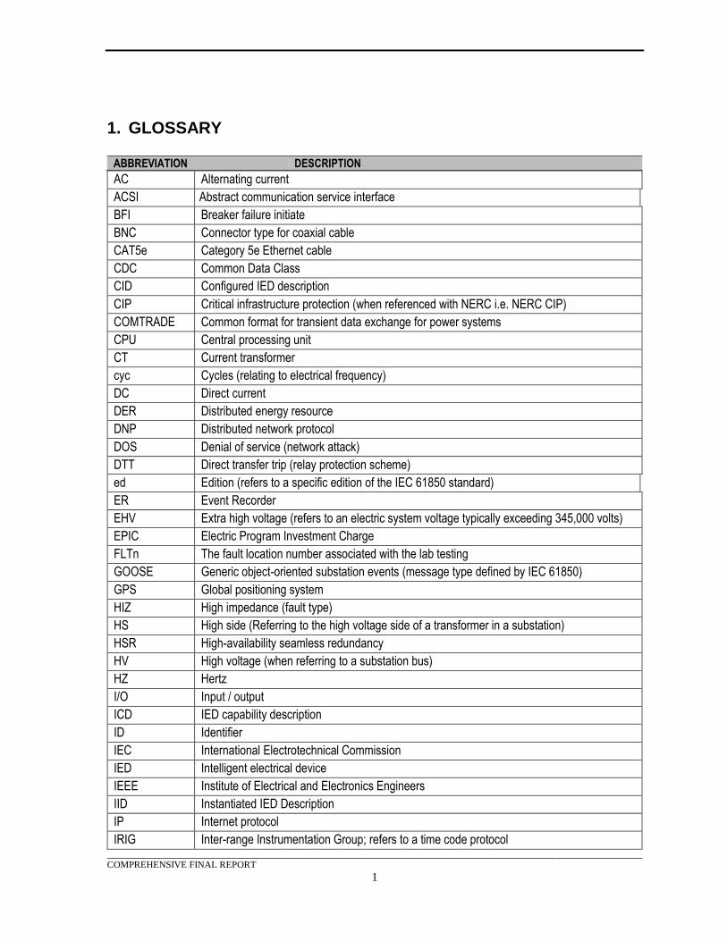
1. GLOSSARY
ABBREVIATION DESCRIPTION
AC Alternating current
ACSI Abstract communication service interface
BFI Breaker failure initiate
BNC Connector type for coaxial cable
CAT5e Category 5e Ethernet cable
CDC Common Data Class
CID Configured IED description
CIP Critical infrastructure protection (when referenced with NERC i.e. NERC CIP)
COMTRADE Common format for transient data exchange for power systems
CPU Central processing unit
CT Current transformer
cyc Cycles (relating to electrical frequency)
DC Direct current
DER Distributed energy resource
DNP Distributed network protocol
DOS Denial of service (network attack)
DTT Direct transfer trip (relay protection scheme)
ed Edition (refers to a specific edition of the IEC 61850 standard)
ER Event Recorder
EHV Extra high voltage (refers to an electric system voltage typically exceeding 345,000 volts)
EPIC Electric Program Investment Charge
FLTn The fault location number associated with the lab testing
GOOSE Generic object-oriented substation events (message type defined by IEC 61850)
GPS Global positioning system
HIZ High impedance (fault type)
HS High side (Referring to the high voltage side of a transformer in a substation)
HSR High-availability seamless redundancy
HV High voltage (when referring to a substation bus)
HZ Hertz
I/O Input / output
ICD IED capability description
ID Identifier
IEC International Electrotechnical Commission
IED Intelligent electrical device
IEEE Institute of Electrical and Electronics Engineers
IID Instantiated IED Description
IP Internet protocol
IRIG Inter-range Instrumentation Group; refers to a time code protocol
COMPREHENSIVE FINAL REPORT
2
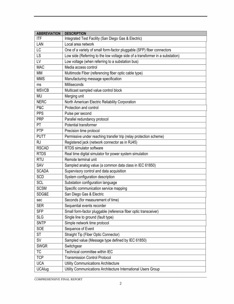
ABBREVIATION DESCRIPTION
ITF Integrated Test Facility (San Diego Gas & Electric)
LAN Local area network
LC One of a variety of small form-factor pluggable (SFP) fiber connectors
LS Low side (Referring to the low voltage side of a transformer in a substation)
LV Low voltage (when referring to a substation bus)
MAC Media access control
MM Multimode Fiber (referencing fiber optic cable type)
MMS Manufacturing message specification
ms Milliseconds
MSVCB Multicast sampled value control block
MU Merging unit
NERC North American Electric Reliability Corporation
P&C Protection and control
PPS Pulse per second
PRP Parallel redundancy protocol
PT Potential transformer
PTP Precision time protocol
PUTT Permissive under reaching transfer trip (relay protection scheme)
RJ Registered jack (network connector as in RJ45)
RSCAD RTDS simulator software
RTDS Real time digital simulator for power system simulation
RTU Remote terminal unit
SAV Sampled analog value (a common data class in IEC 61850)
SCADA Supervisory control and data acquisition
SCD System configuration description
SCL Substation configuration language
SCSM Specific communication service mapping
SDG&E San Diego Gas & Electric
sec Seconds (for measurement of time)
SER Sequential events recorder
SFP Small form-factor pluggable (reference fiber optic transceiver)
SLG Single line to ground (fault type)
SNTP Simple network time protocol
SOE Sequence of Event
ST Straight Tip (Fiber Optic Connector)
SV Sampled value (Message type defined by IEC 61850)
SWGR Switchgear
TC Technical committee within IEC
TCP Transmission Control Protocol
UCA Utility Communications Architecture
UCAIug Utility Communications Architecture International Users Group
COMPREHENSIVE FINAL REPORT
3
ABBREVIATION DESCRIPTION
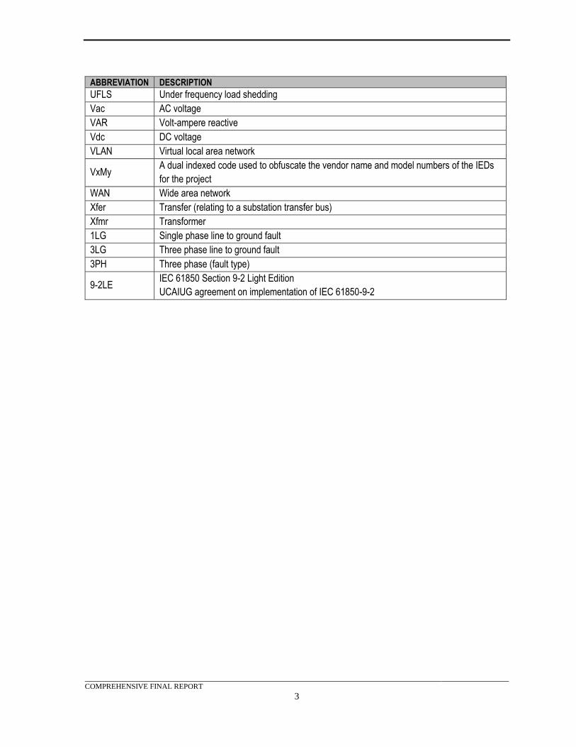
UFLS Under frequency load shedding
Vac AC voltage
VAR Volt-ampere reactive
Vdc DC voltage
VLAN Virtual local area network
VxMy A dual indexed code used to obfuscate the vendor name and model numbers of the IEDs
for the project
WAN Wide area network
Xfer Transfer (relating to a substation transfer bus)
Xfmr Transformer
1LG Single phase line to ground fault
3LG Three phase line to ground fault
3PH Three phase (fault type)
9-2LE IEC 61850 Section 9-2 Light Edition
UCAIUG agreement on implementation of IEC 61850-9-2
COMPREHENSIVE FINAL REPORT
4
2. INTRODUCTION This project was one of three SDG&E Electric Program Investment Charge (EPIC) projects on pre-
commercial demonstration of communications architecture standards for power system operations.
The three projects were:
• Smart Grid Architecture Demonstrations (EPIC-1, Project 1)
o Focus: Communications standards for integration of feeder equipment and
distributed energy resources (DER) into networked automation
• Monitoring, Communication, and Control Infrastructure for Power System Modernization
(EPIC-2, Project 3)
o Focus: Open Field Message Bus
• Modernization of Distribution System and Integration of Distributed Generation and Storage
(EPIC-2, Project 1)
o Focus: IEC 61850 in Substation Network
The principal standard of interest in these three demonstrations was International Electrotechnical
Commission (IEC) 61850, which is an open standard developed by industry stakeholders and
promulgated through the IEC. The intent of these EPIC demonstrations was to increase the body of
knowledge available to aid users in making decisions regarding their future power system
communications architecture. The final reports for all three of these projects were posted on the San
Diego Gas & Electric (SDG&E) EPIC website at www.sdge.com/epic. This body of work was
limited in scope by funding availability in the SDG&E EPIC program, and it is acknowledged that a
much larger body of work in this area is needed.
This report is the comprehensive final report for the third project listed above. The objective of the
project, as stated in SDG&E’s approved EPIC-2 application, was to demonstrate distribution system
infrastructure modernization solutions, including advances in distribution system design to enable use
of new technologies, such as power electronic components, new protection systems, distributed
generation and storage technologies.
The chosen priority for focus of this project was to perform a pre-commercial demonstration in a
laboratory of the International Electrotechnical Commission (IEC) 61850 standard, with specific
emphasis on generic object-oriented substation event (GOOSE) and sampled value (SV) messages.
The demonstration work compared the results to current protective relay practice and performance.
This project also examined the pros and cons of IEC 61850, vendor interoperability issues, and
recommendations on commercial adoption.
The test system for the demonstration facilitated the application of IEC 61850 to a predefined set of
use cases normally found in distribution substations. Protection system performance and
manufacturer interoperability observations were included.
The test system was designed to support a multi-vendor test environment. This enabled the project
team to not only evaluate the protection impacts of a GOOSE and SV based P&C system, but also to
evaluate the state of the industry in integrating IEC 61850 intelligent electronic devices (IEDs). The
primary goals were to demonstrate a multi-vendor IEC 61850 system and determine the impact of
IEC 61850 GOOSE and SV P&C messages on the identified protection use cases. Results from the
demonstration were used to draw conclusions to support the recommendations.

COMPREHENSIVE FINAL REPORT
5
This report includes documentation of the objective, scope, approach, test case descriptions, concept
of operations, specification and design of the test system, laboratory demonstration activities, testing
results, analysis, findings, conclusions, and recommendations.
COMPREHENSIVE FINAL REPORT
6
3. IEC 61850 OVERVIEW AND ISSUES
Focus
The project’s focus was a pre-commercial demonstration of the IEC 61850 standard as applied to a
substation P&C mockup in a laboratory including:
• Specific emphasis on GOOSE and SV messages
• Study of the pros and cons of using this standard with a predefined set of use cases
• Study of vendor interoperability for some of the available IEC 61850 products
• Development of recommendations regarding commercial adoption
This project focused on IEC 61850 implementation, interoperability, control, and protection for
specified use cases. Device configuration and manufacturer interpretation of the standard were key
challenges in the project. The performance of the protection devices was also evaluated in order to
gauge successful implementation of the standard by equipment manufacturers.
IEC 61850
IEC 61850 is an international standard. It is part of the IEC Technical Committee (TC) 57
architecture that provides an open-standard communication architecture for electric power systems.
IEC 61850 is more than just a protocol; it contains methods for digitizing information and for its
transfer within a substation or within the larger power system. IEC 61850 and the related TC-57
standards currently include other domains such as (but not limited to) wind power, hydroelectric
plants, distribution automation, electrical mobility, electrical storage, and distributed energy resources
(DER).
IEC 61850 provides a semantic model of the power system in that the model describes the meaning of
its instances. This standardized model also provides organizational structure for information
exchanges using various types of messaging. The main data exchange methods are MMS, GOOSE,
and SV.
IEC 61850 is a large standard that contains ten parts. This standard includes, among other things, a
defined set of file structures that describes device and system communications, a list of standard data
objects and abstract communications services, standardized object models, a method of mapping
messaging to communication methods, and a testing section to aid in verifying conformance with the
standard.
Advantages of IEC 61850
A complete and comprehensive description of all of the advantages of an IEC 61850 system is
beyond the scope of this section. The bibliography to this report identifies some sources of
background reading material. Some of the more significant items are described below:
IEC 61850 provides standard methods of exchanging data between intelligent electronic devices
(IEDs). By defining a semantic model, multi-manufacturer interoperability is possible. Not only
should this ease configuration effort, but it should greatly reduce the risk that devices from different
manufacturers’ will not communicate.
By standardizing the communication methods and protocols, manufacturers should be able to reduce
development time and costs, thus bringing lower cost products to market sooner. The standardized
COMPREHENSIVE FINAL REPORT
7
file transfer method provides a structured method of exchanging configuration data between devices.
This can reduce end user engineering development time and costs. It also allows for standardized end
user templates that can be reused in each implementation.
One of the big advantages of IEC 61850 P&C schemes is the reduction in control wiring. Control
wiring is expensive to design, install, document and modify. IEC 61850 replaces the majority of the
control wiring with Ethernet cabling that allows multiple communication sessions to be supported
over a single physical media. When fiber optic cabling is employed, additional advantages accrue
due to its noise resistance and isolation from ground potential rise (GPR) inherent in high voltage
substations.
The communications cabling employed with IEC 61850 is essentially self-monitoring due to the
repetitive nature of the messages. Loss of path can be rapidly identified due to message loss. Alarms
can then be initiated to resolve failures before a critical failure occurs. This facilitates continuous
automatic testing and reduces effort to comply with North American Electric Reliability Corporation
(NERC) PRC-005 requirements.
The IEC 61850 semantic model provides for self-descriptive capabilities. Users can browse devices
prior to purchase to identify their capabilities. It simplifies design and configuration as the device
capabilities are standardized, insuring consistency from manufacturer to manufacturer.
United States Adoption of IEC 61850
Adoption of IEC 61850 in the United States has been slow. There are many proposed explanations
for this slow adoption. No single explanation would likely cover all the reasons. The internet
provides a multitude of potential explanations for the slow adoption in the United States and the rest
of North America. Some examples are:
• There is a major investment in older legacy architectures, and migration to a new architecture
will be costly. A business justification is needed.
• The use of some sections of the standard is still new. While MMS and GOOSE are fairly
mature, but SV is still evolving and extensive effort is required to ensure interoperability.
• The changes required to implement an IEC 61850 substation are substantial and not every
end user is willing to undertake the challenge.
• IEC 61850 provides for a very different P&C scheme, which is unfamiliar to many end users
and requires careful change management to succeed.
• Implementing IEC 61850 introduces Ethernet into substations. Potential NERC compliance
exposure is a concern with many end users.
• Testing and maintenance will be different with a P&C scheme based on IEC 61850.
Development of industry accepted processes and methodologies are still evolving.
• Introduction of the new methods and processes will take time and effort.
From the above, it appears that knowledge and familiarity with the IEC 61850 standard contribute to
its limited adoption in the United States. Providing additional information on the application and
implementation of the IEC 61850 standard should provide a means to improve the adoption of this
technology in the United States. Interest has been growing and adoption in the United States now
appears to be accelerating.
COMPREHENSIVE FINAL REPORT
8
Major Thrusts of Project Work
This demonstration project had two major work thrusts. The first was to develop additional
information on the interoperability of IEC 61850 GOOSE and SV products between manufacturers.
The second was to demonstrate the adequacy of an IEC 61850 P&C scheme when compared to the
traditional hardwired scheme.
Knowledge Application
This project demonstrated that the use of IEC 61850 enhances interoperability of multiple
manufacturers’ products. It also demonstrated that SV and GOOSE could provide protection system
performance that was equal to or better than the tradition hardwired solution. This report provides
support for these assertions and should aid prospective adopters of IEC 61850 by providing assurance
that the IEC 61850 P&C scheme will not degrade protection capabilities of substations.
COMPREHENSIVE FINAL REPORT
9
4. OVERVIEW OF APPROACH Power system automation and communication technologies are improving and becoming more robust.
After studying different options and based on discussion with internal stakeholders, the project team
chose pre-commercial demonstration of IEC 61850 for substation protection, control, and automation
as the project focus.
The project and pre-commercial demonstration were anticipated to help determine whether the
utilization of IEC 61850 based systems could replace existing substation automation and protection
functions without compromising characteristics such as selectivity, speed, security and reliability of
present substation P&C systems. In this project, existing standards for substation protection,
automation and control architecture were used as a starting point. These existing standards were
mapped to the new IEC 61850 standard. Bridges between the missing links of the technology were
created to provide a transition to an IEC 61850 based protection system. This project implemented
test cases in the test system that tested the application of IEC 61850 GOOSE and SV to the identified
use cases (breaker failure protection, line protection, bus protection, transformer protection,
capacitor/reactor feeder protection, capacitor and reactor protection, and frequency deviation
protection).
The use cases were then refined into test cases. Test cases provided additional details so that the
performance of the test system could be evaluated for various protection scenarios. These scenarios
included in-zone and out-of-zone faults for individual protection elements. In addition, test cases
included various control scenarios for capacitor and reactor banks.
The test system equipment was initially installed in racks in the contractor’s IEC 61850 lab. All
equipment was mounted in 19” racks and connected to power sources. Communication cabling was
connected to each device in accordance with Appendix C. IEDs settings were then installed and
published data sets were assigned in accordance with the tables in Appendix D. IED subscriptions
were also assigned per the tables in Appendix C.
Test scenarios were developed using the Real-Time Digital Simulator (RTDS) and saved as
COMTRADE (common format for transient data exchange for power systems) files. These files were
then re-played by the relay test sets. The relay test sets injected currents and voltages into the
appropriate MUs for processing by the relays. This process enhanced repeatability of the test
parameters and reduced testing times. These files were also used as inputs for the RTDS testing that
was performed at the end of the project. These tests files utilized actual SDG&E simulations as
developed with the RTDS.
For this project, interoperability was considered to have been achieved if the MUs and relays could
accurately publish, subscribe, and respond to IEC 61850 messages within the operational time limits
of the protection devices.
Pre-Commercial Demonstration
The pre-commercial demonstration was conducted while the test system was located in the
contractor’s IEC 61850 lab. This provided team members with the opportunity to observe the
functional tests performed on each test case and verify results. Additional time was provided to
explain each test case and review COMTRADE plots to verify that the team members agreed with the
relay operation and timing results.
COMPREHENSIVE FINAL REPORT
10
Additional Demonstration at Integrated Test Facility (ITF)
Additional tests of selected use cases were performed at SDG&E’s ITF using direct signals from the
RTDS simulations, as described above. This repeat of selected use case tests allowed additional
stakeholders to witness testing and have a chance to discuss the results.
Technology Transfer Activities During the Project
This project investigated a multi-vendor IEC 61850 test system that utilized GOOSE, SV, and MMS.
It was predominantly a technology demonstration project. Technology transfer activities were
performed throughout the project. These included on-site meetings, conference calls, web based
presentations, and direct face-to-face meetings. Various workshops and training classes were held as
part of the pre-commercial demonstration phase of the project. System architecture, RTDS, test
setup, configuring software and relay settings were examples of activities and topics which were
covered during the training.
Hands-on training was provided at various times throughout the project for the project team’s
engineers. This training included IEC 61850 configuration and one-on-one time with relay
manufacturers’ technical experts while they performed troubleshooting on the test system, when it
was located in the contractor’s IEC 61850 lab. Additional hands-on training was provided for the
project team’s members who attended the pre-commercial demonstration held at the contractor’s IEC
61850 lab.
Classroom Training
A four day IEC 61850 training class was provided to the project team that covered the basics of IEC
61850 (i.e. operations, theory, standard, hands-on configuration, etc.).
Software Training
All of the manufacturers’ configuration software and associated licenses were provided to the project
team. Training was held to review each software package and how to configure the associated
manufacturer’s IEC 61850 IEDs. Additionally, the review of the specific project files was done and
delivered to the project team (setting files, configurations, SCL files, etc.) for future reference.
Pre-commercial Demonstration Training
Additional time was devoted to training during the pre-commercial demonstration. This allowed
additional stakeholders to obtain background on the design and development of the test system.
During the pre-commercial demonstration, the protection engineers provided additional explanations
and background to allow stakeholders to improve their understanding of the test cases.
Hands-On Training with Vendors
Two of the main suppliers were at the lab during the configuration effort. Stakeholders were invited
to participate. Stakeholders were on-site for configuration and trouble shooting. This provided an
opportunity for the stakeholders to gain additional insight into the configuration of the IEDs in the
test system.
COMPREHENSIVE FINAL REPORT
11
5. BASELINE ASSESSMENT A thorough investigation into SDG&E’s current standards and selected existing distribution
(138/12 kV or 69/12 kV) substations was conducted to provide a baseline on the SDG&E’s
philosophies and practices. This provided a reference point to which the conceptual IEC 61850
substation and the IEC 61850 lab demonstrations could be compared. Creating this reference point
was important for future identification of the impacts of IEC 61850 substation design and
implementation as well as the performance and functionality of the substation.
Several aspects of the existing substations including standard distribution substation electrical
drawing package, typical protection system architecture and preferred schemes, protection use cases,
communications, time synchronization, and the local operator interfaces were examined. These were
included due to the anticipated changes associated with moving toward an IEC 61850 substation.
The baseline was created from a combination of standard drawings, as-built drawings from existing
sites, relay settings from existing schemes, as well as discussions with the project team.
A list of anticipated differences for a complete IEC 61850 distribution substation was compiled.
Because it was not possible to foresee all potential changes, this list was intended as a starting point
and was subject to change as this project progressed. During the project, the list was expanded and
can be referenced below:
• Device Changes
o Within the scope of the project, relays and other IEDs will be changed to IEC 61850
compliant devices with SV and GOOSE protocols
o Merging units will be added in the substation yard with SV and GOOSE protocols
o Additional network switches will be added to provide for separate process buses and
the station bus
o Substation battery banks may need to be enlarged to accommodate the additional
direct current (DC) load associated with the MUs and network switches
o Panel meters, annunciators, and RTUs can be selected to take advantage of the new
substation communications network
• Wiring Changes
o Current transformer (CT) and potential transformer (PT) wiring of substation yard
devices will not go back to the control shelter. This wiring will be run to MUs and
kept as close to the associated CT and PT as reasonably possible
o Test switches will be relocated from the control shelter to the substation yard with the
MUs
o When practical, substation yard device status and alarm contacts that were wired
back to the control shelter will be wired into MUs for transmission by GOOSE or
MMS
o Wiring to panel meters, annunciators, and RTUS can be reduced when these items
communicate over the new substation communications network
• Fiber Optics Cables
o Fiber optic cables will be run from the control shelter to each of the MUs in the
substation yard
o Fiber optic patch panels on both the MU side and the control shelter side will be
necessary to facilitate testing and troubleshooting
o Fiber optic patch cables will be required for connections between patch panels and
IEDs
COMPREHENSIVE FINAL REPORT
12
• Communications Changes
o The station will be broken up into independent local area networks (LANs) for each
station bus and process bus
o Protection relays will require multiple Ethernet connections to the station bus and the
applicable process bus
• Documentation Changes
o Updates to existing standards and drawings will be required
COMPREHENSIVE FINAL REPORT
13
6. TEST CASES This project implemented test cases in the test system that tested the application of IEC 61850
GOOSE and SV to the identified use cases. These use cases were defined by the project team at the
start of the project. Use cases identified were:
• Breaker failure protection
• Line protection
• Bus protection
• Transformer protection
• Capacitor/reactor feeder protection
• Capacitor and reactor protection
• Frequency deviation protection
Use cases were further refined into test cases as the project proceeded. The test cases were used to
compare performance of the test system to the existing protection equipment. Drawings for each test
case were included in this report as Appendix A.
• For each test case, these drawings show the general substation equipment arrangement and
the applicable bus (process bus #1, process bus #2, or station bus) with the case specific IEDs
highlighted
• MUs were connected to simulated instrument transformers (test set/RTDS simulation inputs)
with blue solid lines that indicate the location of the simulated instrument transformers. The
SV streams were shown with blue dotted lines. From the identified MUs, these lines could be
traced to highlighted subscribing relays. The relays’ published GOOSE messages were
shown with thin black lines, which could be traced to brown “virtual buses” at each
highlighted MU. The subscribing MUs’ connection to the “virtual buses” was then indicated
with a brown arrow
• The MUs breaker control and indication was indicated with a purple arrow. Once the MU
received the applicable indication a thin black line could be traced back to another brown
“virtual bus”, at the subscribing relays. Another brown arrow showed the communication
from the relay “virtual bus to the subscribing relay
• Red lines showed the transfer trip connection between the local and remote relays used for
line protection.
Each test case is described below:
Test Case #1 – Breaker Failure Protection (50BF)
The breaker failure protection test case was intended to simulate a typical breaker failure relay
application for a 69 or 138 kV breaker. The test was run with one relay set consisting of the relay
receiving breaker current signals from the instrument transformers via MU and IEC 61850-9-2
process bus SV. The breaker failure relay received breaker-failure initiate (BFI) notification by
GOOSE from the line protection relays, and tripped all the bus breakers if the line breaker failed to
trip. Trip and indication signals were published via GOOSE messages.
COMPREHENSIVE FINAL REPORT
14
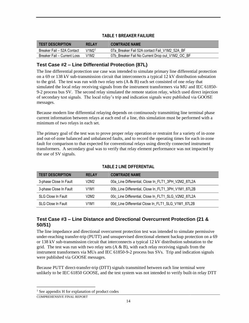
TABLE 1 BREAKER FAILIURE
TEST DESCRIPTION RELAY COMTRADE NAME
Breaker Fail – 52A Contact V1M21 07a_Breaker Fail 52A contact Fail_V1M2_52A_BF
Breaker Fail – Current Loss V1M2 07b_Breaker Fail No Current Drop out_V1M2_OC_BF
Test Case #2 – Line Differential Protection (87L)
The line differential protection use case was intended to simulate primary line differential protection
on a 69 or 138 kV sub-transmission circuit that interconnects a typical 12 kV distribution substation
to the grid. The test was run with two relay sets (A & B) each set consisted of one relay that
simulated the local relay receiving signals from the instrument transformers via MU and IEC 61850-
9-2 process bus SV. The second relay simulated the remote station relay, which used direct injection
of secondary test signals. The local relay’s trip and indication signals were published via GOOSE
messages.
Because modern line differential relaying depends on continuously transmitting line terminal phase
current information between relays at each end of a line, this simulation must be performed with a
minimum of two relays in each set.
The primary goal of the test was to prove proper relay operation or restraint for a variety of in-zone
and out-of-zone balanced and unbalanced faults, and to record the operating times for each in-zone
fault for comparison to that expected for conventional relays using directly connected instrument
transformers. A secondary goal was to verify that relay element performance was not impacted by
the use of SV signals.
TABLE 2 LINE DIFFERENTIAL
TEST DESCRIPTION RELAY COMTRADE NAME
3-phase Close In Fault V2M2 00a_Line Differential, Close In_FLT1_3PH_V2M2_87L2A
3-phase Close In Fault V1M1 00b_Line Differential, Close In_FLT1_3PH_V1M1_87L2B
SLG Close In Fault V2M2 00c_Line Differential, Close In_FLT1_SLG_V2M2_87L2A
SLG Close In Fault V1M1 00d_Line Differential Close In_FLT1_SLG_V1M1_87L2B
Test Case #3 – Line Distance and Directional Overcurrent Protection (21 & 50/51)
The line impedance and directional overcurrent protection test was intended to simulate permissive
under-reaching transfer-trip (PUTT) and unsupervised directional element backup protection on a 69
or 138 kV sub-transmission circuit that interconnects a typical 12 kV distribution substation to the
grid. The test was run with two relay sets (A & B), with each relay receiving signals from the
instrument transformers via MUs and IEC 61850-9-2 process bus SVs. Trip and indication signals
were published via GOOSE messages.
Because PUTT direct-transfer-trip (DTT) signals transmitted between each line terminal were
unlikely to be IEC 61850 GOOSE, and the test system was not intended to verify built-in relay DTT
1 See appendix H for explanation of product codes
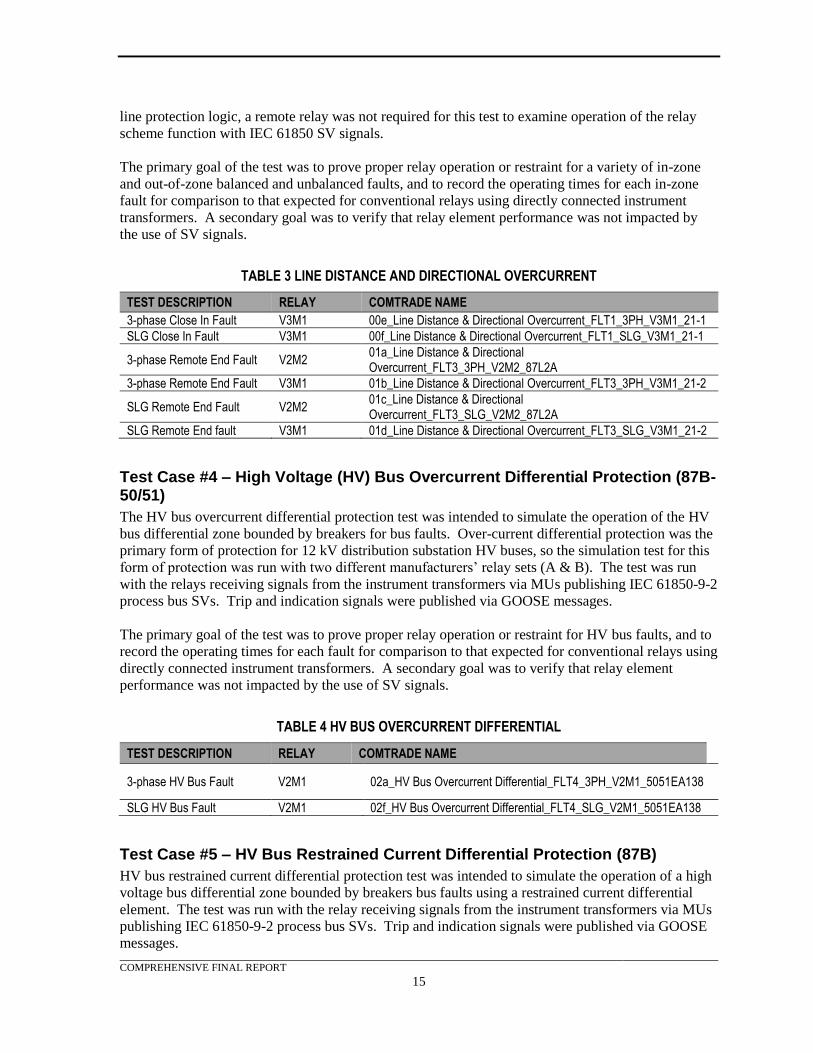
COMPREHENSIVE FINAL REPORT
15
line protection logic, a remote relay was not required for this test to examine operation of the relay
scheme function with IEC 61850 SV signals.
The primary goal of the test was to prove proper relay operation or restraint for a variety of in-zone
and out-of-zone balanced and unbalanced faults, and to record the operating times for each in-zone
fault for comparison to that expected for conventional relays using directly connected instrument
transformers. A secondary goal was to verify that relay element performance was not impacted by
the use of SV signals.
TABLE 3 LINE DISTANCE AND DIRECTIONAL OVERCURRENT
TEST DESCRIPTION RELAY COMTRADE NAME
3-phase Close In Fault V3M1 00e_Line Distance & Directional Overcurrent_FLT1_3PH_V3M1_21-1
SLG Close In Fault V3M1 00f_Line Distance & Directional Overcurrent_FLT1_SLG_V3M1_21-1
3-phase Remote End Fault V2M2 01a_Line Distance & Directional Overcurrent_FLT3_3PH_V2M2_87L2A
3-phase Remote End Fault V3M1 01b_Line Distance & Directional Overcurrent_FLT3_3PH_V3M1_21-2
SLG Remote End Fault V2M2 01c_Line Distance & Directional Overcurrent_FLT3_SLG_V2M2_87L2A
SLG Remote End fault V3M1 01d_Line Distance & Directional Overcurrent_FLT3_SLG_V3M1_21-2
Test Case #4 – High Voltage (HV) Bus Overcurrent Differential Protection (87B-50/51)
The HV bus overcurrent differential protection test was intended to simulate the operation of the HV
bus differential zone bounded by breakers for bus faults. Over-current differential protection was the
primary form of protection for 12 kV distribution substation HV buses, so the simulation test for this
form of protection was run with two different manufacturers’ relay sets (A & B). The test was run
with the relays receiving signals from the instrument transformers via MUs publishing IEC 61850-9-2
process bus SVs. Trip and indication signals were published via GOOSE messages.
The primary goal of the test was to prove proper relay operation or restraint for HV bus faults, and to
record the operating times for each fault for comparison to that expected for conventional relays using
directly connected instrument transformers. A secondary goal was to verify that relay element
performance was not impacted by the use of SV signals.
TABLE 4 HV BUS OVERCURRENT DIFFERENTIAL
TEST DESCRIPTION RELAY COMTRADE NAME
3-phase HV Bus Fault V2M1 02a_HV Bus Overcurrent Differential_FLT4_3PH_V2M1_5051EA138
SLG HV Bus Fault V2M1 02f_HV Bus Overcurrent Differential_FLT4_SLG_V2M1_5051EA138
Test Case #5 – HV Bus Restrained Current Differential Protection (87B)
HV bus restrained current differential protection test was intended to simulate the operation of a high
voltage bus differential zone bounded by breakers bus faults using a restrained current differential
element. The test was run with the relay receiving signals from the instrument transformers via MUs
publishing IEC 61850-9-2 process bus SVs. Trip and indication signals were published via GOOSE
messages.
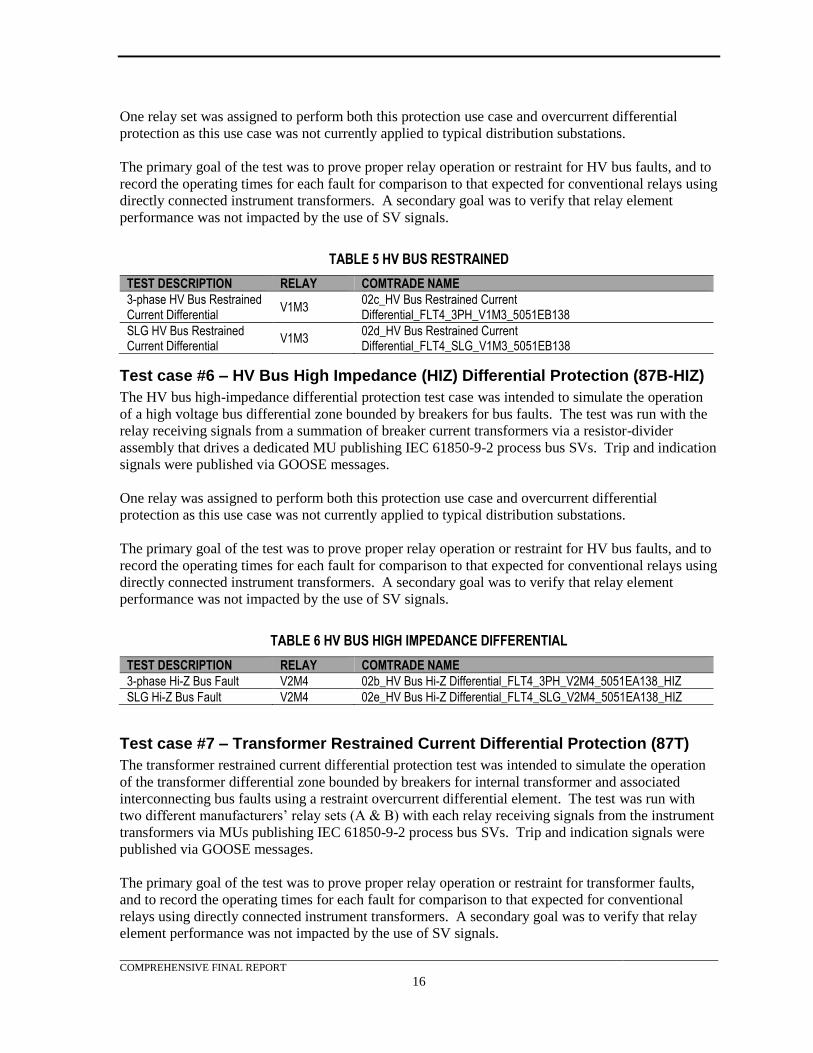
COMPREHENSIVE FINAL REPORT
16
One relay set was assigned to perform both this protection use case and overcurrent differential
protection as this use case was not currently applied to typical distribution substations.
The primary goal of the test was to prove proper relay operation or restraint for HV bus faults, and to
record the operating times for each fault for comparison to that expected for conventional relays using
directly connected instrument transformers. A secondary goal was to verify that relay element
performance was not impacted by the use of SV signals.
TABLE 5 HV BUS RESTRAINED
TEST DESCRIPTION RELAY COMTRADE NAME
3-phase HV Bus Restrained Current Differential
V1M3 02c_HV Bus Restrained Current Differential_FLT4_3PH_V1M3_5051EB138
SLG HV Bus Restrained Current Differential
V1M3 02d_HV Bus Restrained Current Differential_FLT4_SLG_V1M3_5051EB138
Test case #6 – HV Bus High Impedance (HIZ) Differential Protection (87B-HIZ)
The HV bus high-impedance differential protection test case was intended to simulate the operation
of a high voltage bus differential zone bounded by breakers for bus faults. The test was run with the
relay receiving signals from a summation of breaker current transformers via a resistor-divider
assembly that drives a dedicated MU publishing IEC 61850-9-2 process bus SVs. Trip and indication
signals were published via GOOSE messages.
One relay was assigned to perform both this protection use case and overcurrent differential
protection as this use case was not currently applied to typical distribution substations.
The primary goal of the test was to prove proper relay operation or restraint for HV bus faults, and to
record the operating times for each fault for comparison to that expected for conventional relays using
directly connected instrument transformers. A secondary goal was to verify that relay element
performance was not impacted by the use of SV signals.
TABLE 6 HV BUS HIGH IMPEDANCE DIFFERENTIAL
TEST DESCRIPTION RELAY COMTRADE NAME
3-phase Hi-Z Bus Fault V2M4 02b_HV Bus Hi-Z Differential_FLT4_3PH_V2M4_5051EA138_HIZ
SLG Hi-Z Bus Fault V2M4 02e_HV Bus Hi-Z Differential_FLT4_SLG_V2M4_5051EA138_HIZ
Test case #7 – Transformer Restrained Current Differential Protection (87T)
The transformer restrained current differential protection test was intended to simulate the operation
of the transformer differential zone bounded by breakers for internal transformer and associated
interconnecting bus faults using a restraint overcurrent differential element. The test was run with
two different manufacturers’ relay sets (A & B) with each relay receiving signals from the instrument
transformers via MUs publishing IEC 61850-9-2 process bus SVs. Trip and indication signals were
published via GOOSE messages.
The primary goal of the test was to prove proper relay operation or restraint for transformer faults,
and to record the operating times for each fault for comparison to that expected for conventional
relays using directly connected instrument transformers. A secondary goal was to verify that relay
element performance was not impacted by the use of SV signals.
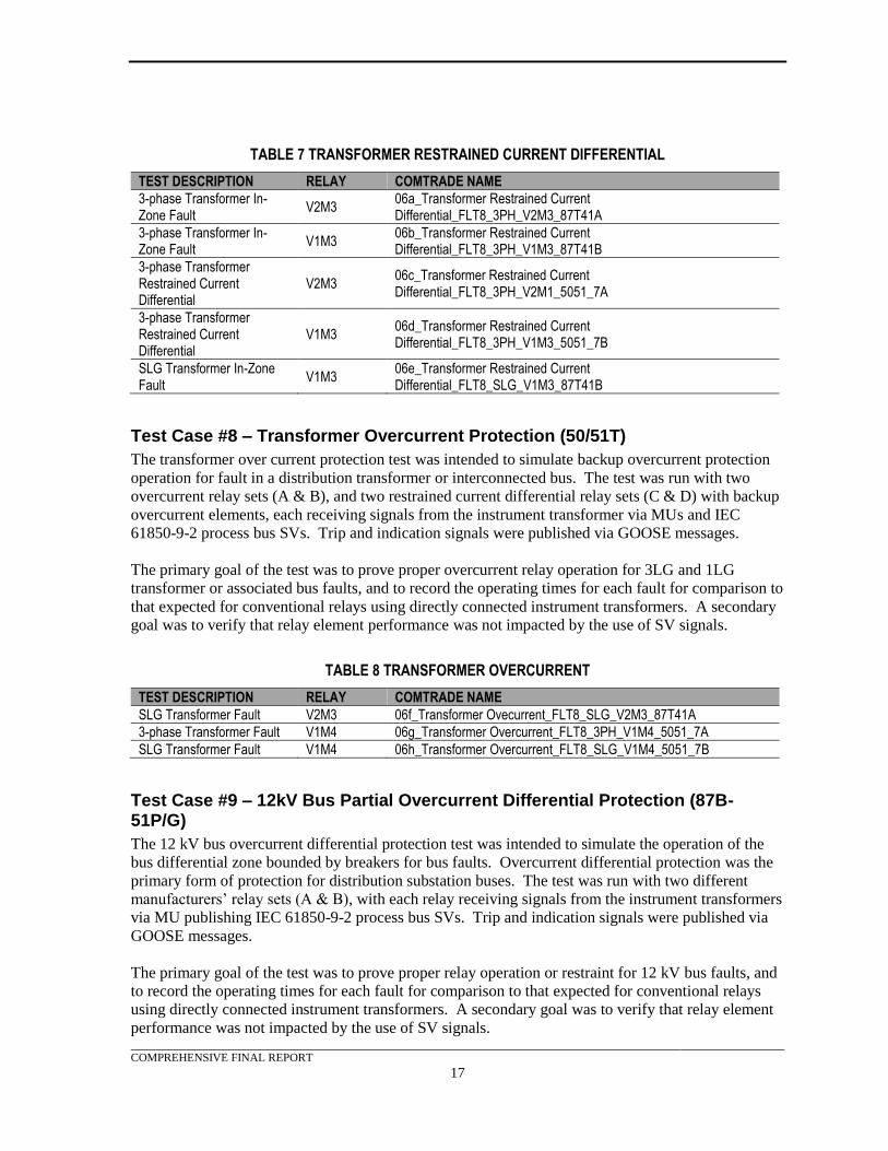
COMPREHENSIVE FINAL REPORT
17
TABLE 7 TRANSFORMER RESTRAINED CURRENT DIFFERENTIAL
TEST DESCRIPTION RELAY COMTRADE NAME
3-phase Transformer In-Zone Fault
V2M3 06a_Transformer Restrained Current Differential_FLT8_3PH_V2M3_87T41A
3-phase Transformer In-Zone Fault
V1M3 06b_Transformer Restrained Current Differential_FLT8_3PH_V1M3_87T41B
3-phase Transformer Restrained Current Differential
V2M3 06c_Transformer Restrained Current Differential_FLT8_3PH_V2M1_5051_7A
3-phase Transformer Restrained Current Differential
V1M3 06d_Transformer Restrained Current Differential_FLT8_3PH_V1M3_5051_7B
SLG Transformer In-Zone Fault
V1M3 06e_Transformer Restrained Current Differential_FLT8_SLG_V1M3_87T41B
Test Case #8 – Transformer Overcurrent Protection (50/51T)
The transformer over current protection test was intended to simulate backup overcurrent protection
operation for fault in a distribution transformer or interconnected bus. The test was run with two
overcurrent relay sets (A & B), and two restrained current differential relay sets (C & D) with backup
overcurrent elements, each receiving signals from the instrument transformer via MUs and IEC
61850-9-2 process bus SVs. Trip and indication signals were published via GOOSE messages.
The primary goal of the test was to prove proper overcurrent relay operation for 3LG and 1LG
transformer or associated bus faults, and to record the operating times for each fault for comparison to
that expected for conventional relays using directly connected instrument transformers. A secondary
goal was to verify that relay element performance was not impacted by the use of SV signals.
TABLE 8 TRANSFORMER OVERCURRENT
TEST DESCRIPTION RELAY COMTRADE NAME
SLG Transformer Fault V2M3 06f_Transformer Ovecurrent_FLT8_SLG_V2M3_87T41A
3-phase Transformer Fault V1M4 06g_Transformer Overcurrent_FLT8_3PH_V1M4_5051_7A
SLG Transformer Fault V1M4 06h_Transformer Overcurrent_FLT8_SLG_V1M4_5051_7B
Test Case #9 – 12kV Bus Partial Overcurrent Differential Protection (87B-51P/G)
The 12 kV bus overcurrent differential protection test was intended to simulate the operation of the
bus differential zone bounded by breakers for bus faults. Overcurrent differential protection was the
primary form of protection for distribution substation buses. The test was run with two different
manufacturers’ relay sets (A & B), with each relay receiving signals from the instrument transformers
via MU publishing IEC 61850-9-2 process bus SVs. Trip and indication signals were published via
GOOSE messages.
The primary goal of the test was to prove proper relay operation or restraint for 12 kV bus faults, and
to record the operating times for each fault for comparison to that expected for conventional relays
using directly connected instrument transformers. A secondary goal was to verify that relay element
performance was not impacted by the use of SV signals.
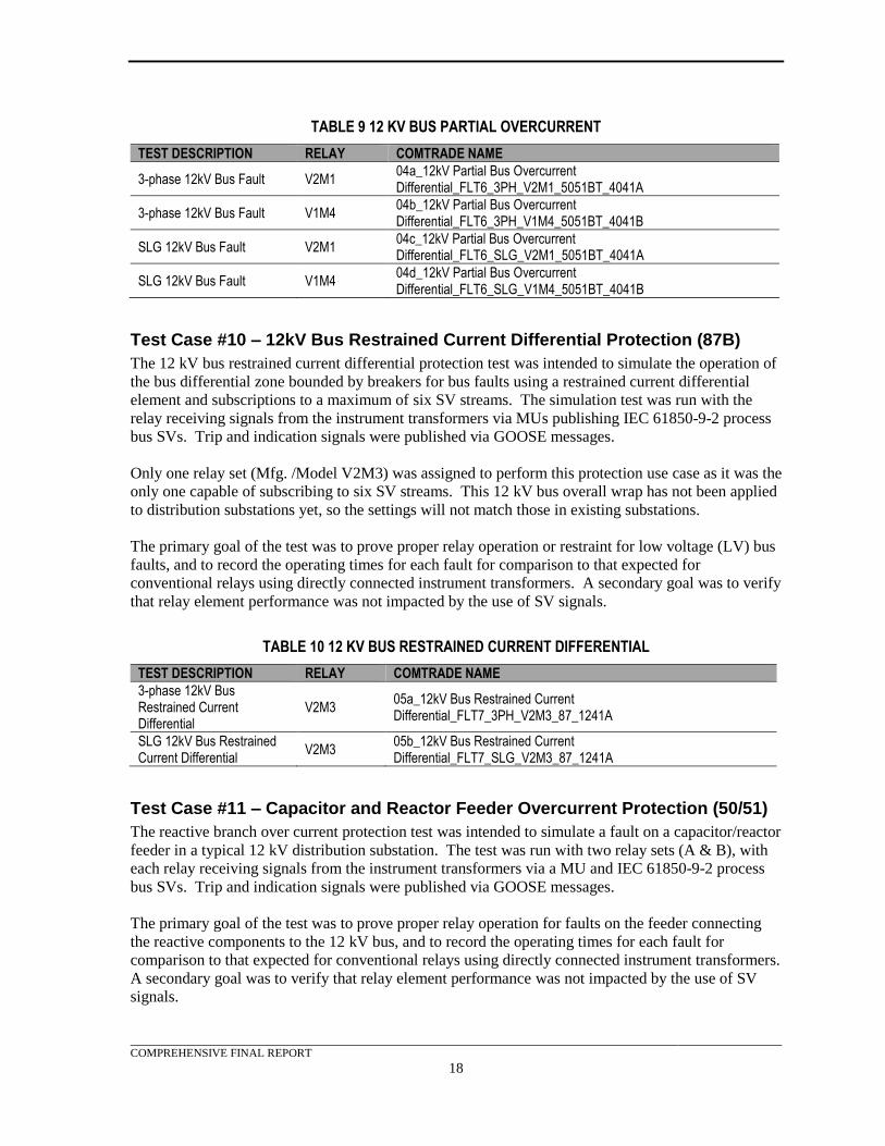
COMPREHENSIVE FINAL REPORT
18
TABLE 9 12 KV BUS PARTIAL OVERCURRENT
TEST DESCRIPTION RELAY COMTRADE NAME
3-phase 12kV Bus Fault V2M1 04a_12kV Partial Bus Overcurrent Differential_FLT6_3PH_V2M1_5051BT_4041A
3-phase 12kV Bus Fault V1M4 04b_12kV Partial Bus Overcurrent Differential_FLT6_3PH_V1M4_5051BT_4041B
SLG 12kV Bus Fault V2M1 04c_12kV Partial Bus Overcurrent Differential_FLT6_SLG_V2M1_5051BT_4041A
SLG 12kV Bus Fault V1M4 04d_12kV Partial Bus Overcurrent Differential_FLT6_SLG_V1M4_5051BT_4041B
Test Case #10 – 12kV Bus Restrained Current Differential Protection (87B)
The 12 kV bus restrained current differential protection test was intended to simulate the operation of
the bus differential zone bounded by breakers for bus faults using a restrained current differential
element and subscriptions to a maximum of six SV streams. The simulation test was run with the
relay receiving signals from the instrument transformers via MUs publishing IEC 61850-9-2 process
bus SVs. Trip and indication signals were published via GOOSE messages.
Only one relay set (Mfg. /Model V2M3) was assigned to perform this protection use case as it was the
only one capable of subscribing to six SV streams. This 12 kV bus overall wrap has not been applied
to distribution substations yet, so the settings will not match those in existing substations.
The primary goal of the test was to prove proper relay operation or restraint for low voltage (LV) bus
faults, and to record the operating times for each fault for comparison to that expected for
conventional relays using directly connected instrument transformers. A secondary goal was to verify
that relay element performance was not impacted by the use of SV signals.
TABLE 10 12 KV BUS RESTRAINED CURRENT DIFFERENTIAL
TEST DESCRIPTION RELAY COMTRADE NAME
3-phase 12kV Bus Restrained Current Differential
V2M3 05a_12kV Bus Restrained Current Differential_FLT7_3PH_V2M3_87_1241A
SLG 12kV Bus Restrained Current Differential
V2M3 05b_12kV Bus Restrained Current Differential_FLT7_SLG_V2M3_87_1241A
Test Case #11 – Capacitor and Reactor Feeder Overcurrent Protection (50/51)
The reactive branch over current protection test was intended to simulate a fault on a capacitor/reactor
feeder in a typical 12 kV distribution substation. The test was run with two relay sets (A & B), with
each relay receiving signals from the instrument transformers via a MU and IEC 61850-9-2 process
bus SVs. Trip and indication signals were published via GOOSE messages.
The primary goal of the test was to prove proper relay operation for faults on the feeder connecting
the reactive components to the 12 kV bus, and to record the operating times for each fault for
comparison to that expected for conventional relays using directly connected instrument transformers.
A secondary goal was to verify that relay element performance was not impacted by the use of SV
signals.
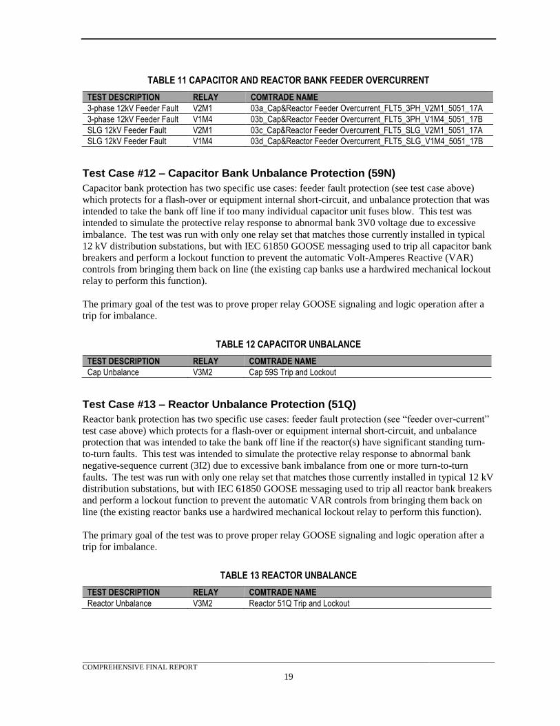
COMPREHENSIVE FINAL REPORT
19
TABLE 11 CAPACITOR AND REACTOR BANK FEEDER OVERCURRENT
TEST DESCRIPTION RELAY COMTRADE NAME
3-phase 12kV Feeder Fault V2M1 03a_Cap&Reactor Feeder Overcurrent_FLT5_3PH_V2M1_5051_17A
3-phase 12kV Feeder Fault V1M4 03b_Cap&Reactor Feeder Overcurrent_FLT5_3PH_V1M4_5051_17B
SLG 12kV Feeder Fault V2M1 03c_Cap&Reactor Feeder Overcurrent_FLT5_SLG_V2M1_5051_17A
SLG 12kV Feeder Fault V1M4 03d_Cap&Reactor Feeder Overcurrent_FLT5_SLG_V1M4_5051_17B
Test Case #12 – Capacitor Bank Unbalance Protection (59N)
Capacitor bank protection has two specific use cases: feeder fault protection (see test case above)
which protects for a flash-over or equipment internal short-circuit, and unbalance protection that was
intended to take the bank off line if too many individual capacitor unit fuses blow. This test was
intended to simulate the protective relay response to abnormal bank 3V0 voltage due to excessive
imbalance. The test was run with only one relay set that matches those currently installed in typical
12 kV distribution substations, but with IEC 61850 GOOSE messaging used to trip all capacitor bank
breakers and perform a lockout function to prevent the automatic Volt-Amperes Reactive (VAR)
controls from bringing them back on line (the existing cap banks use a hardwired mechanical lockout
relay to perform this function).
The primary goal of the test was to prove proper relay GOOSE signaling and logic operation after a
trip for imbalance.
TABLE 12 CAPACITOR UNBALANCE
TEST DESCRIPTION RELAY COMTRADE NAME
Cap Unbalance V3M2 Cap 59S Trip and Lockout
Test Case #13 – Reactor Unbalance Protection (51Q)
Reactor bank protection has two specific use cases: feeder fault protection (see “feeder over-current”
test case above) which protects for a flash-over or equipment internal short-circuit, and unbalance
protection that was intended to take the bank off line if the reactor(s) have significant standing turn-
to-turn faults. This test was intended to simulate the protective relay response to abnormal bank
negative-sequence current (3I2) due to excessive bank imbalance from one or more turn-to-turn
faults. The test was run with only one relay set that matches those currently installed in typical 12 kV
distribution substations, but with IEC 61850 GOOSE messaging used to trip all reactor bank breakers
and perform a lockout function to prevent the automatic VAR controls from bringing them back on
line (the existing reactor banks use a hardwired mechanical lockout relay to perform this function).
The primary goal of the test was to prove proper relay GOOSE signaling and logic operation after a
trip for imbalance.
TABLE 13 REACTOR UNBALANCE
TEST DESCRIPTION RELAY COMTRADE NAME
Reactor Unbalance V3M2 Reactor 51Q Trip and Lockout
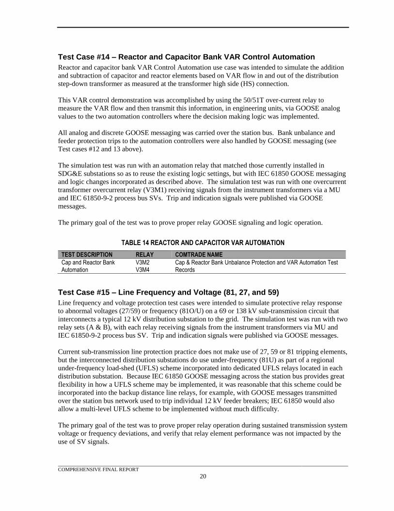
COMPREHENSIVE FINAL REPORT
20
Test Case #14 – Reactor and Capacitor Bank VAR Control Automation
Reactor and capacitor bank VAR Control Automation use case was intended to simulate the addition
and subtraction of capacitor and reactor elements based on VAR flow in and out of the distribution
step-down transformer as measured at the transformer high side (HS) connection.
This VAR control demonstration was accomplished by using the 50/51T over-current relay to
measure the VAR flow and then transmit this information, in engineering units, via GOOSE analog
values to the two automation controllers where the decision making logic was implemented.
All analog and discrete GOOSE messaging was carried over the station bus. Bank unbalance and
feeder protection trips to the automation controllers were also handled by GOOSE messaging (see
Test cases #12 and 13 above).
The simulation test was run with an automation relay that matched those currently installed in
SDG&E substations so as to reuse the existing logic settings, but with IEC 61850 GOOSE messaging
and logic changes incorporated as described above. The simulation test was run with one overcurrent
transformer overcurrent relay (V3M1) receiving signals from the instrument transformers via a MU
and IEC 61850-9-2 process bus SVs. Trip and indication signals were published via GOOSE
messages.
The primary goal of the test was to prove proper relay GOOSE signaling and logic operation.
TABLE 14 REACTOR AND CAPACITOR VAR AUTOMATION
TEST DESCRIPTION RELAY COMTRADE NAME
Cap and Reactor Bank Automation
V3M2 V3M4
Cap & Reactor Bank Unbalance Protection and VAR Automation Test Records
Test Case #15 – Line Frequency and Voltage (81, 27, and 59)
Line frequency and voltage protection test cases were intended to simulate protective relay response
to abnormal voltages (27/59) or frequency (81O/U) on a 69 or 138 kV sub-transmission circuit that
interconnects a typical 12 kV distribution substation to the grid. The simulation test was run with two
relay sets (A & B), with each relay receiving signals from the instrument transformers via MU and
IEC 61850-9-2 process bus SV. Trip and indication signals were published via GOOSE messages.
Current sub-transmission line protection practice does not make use of 27, 59 or 81 tripping elements,
but the interconnected distribution substations do use under-frequency (81U) as part of a regional
under-frequency load-shed (UFLS) scheme incorporated into dedicated UFLS relays located in each
distribution substation. Because IEC 61850 GOOSE messaging across the station bus provides great
flexibility in how a UFLS scheme may be implemented, it was reasonable that this scheme could be
incorporated into the backup distance line relays, for example, with GOOSE messages transmitted
over the station bus network used to trip individual 12 kV feeder breakers; IEC 61850 would also
allow a multi-level UFLS scheme to be implemented without much difficulty.
The primary goal of the test was to prove proper relay operation during sustained transmission system
voltage or frequency deviations, and verify that relay element performance was not impacted by the
use of SV signals.
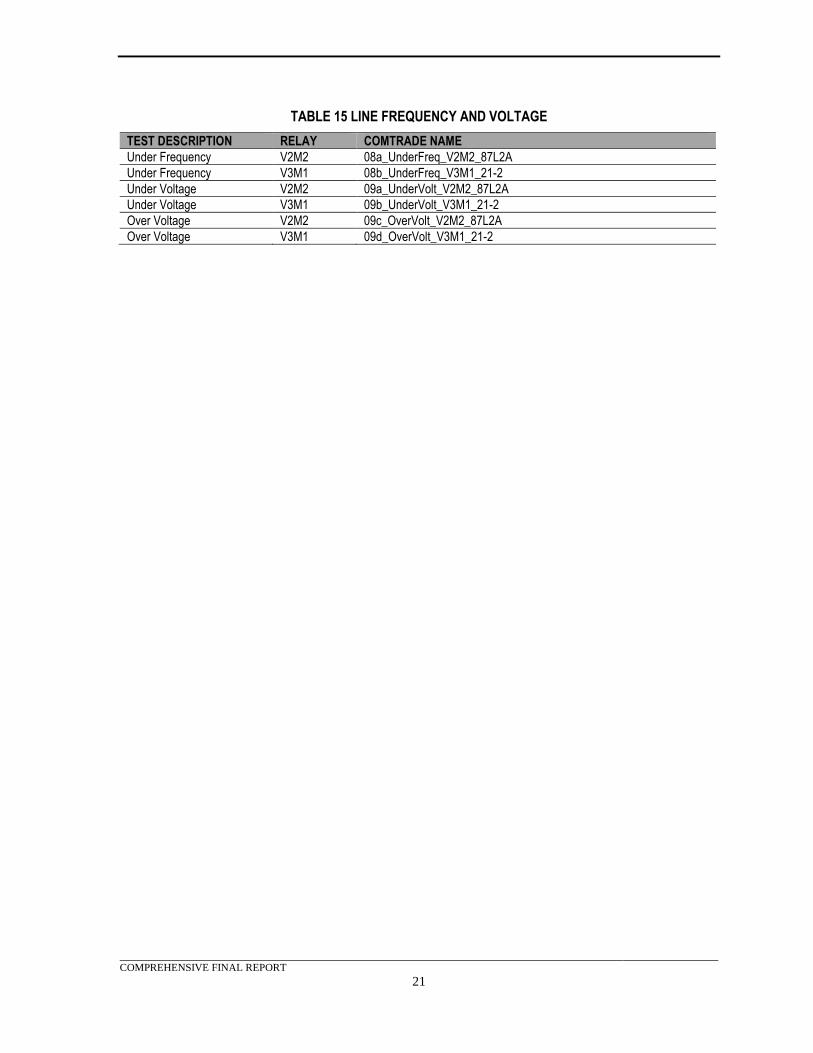
COMPREHENSIVE FINAL REPORT
21
TABLE 15 LINE FREQUENCY AND VOLTAGE
TEST DESCRIPTION RELAY COMTRADE NAME
Under Frequency V2M2 08a_UnderFreq_V2M2_87L2A
Under Frequency V3M1 08b_UnderFreq_V3M1_21-2
Under Voltage V2M2 09a_UnderVolt_V2M2_87L2A
Under Voltage V3M1 09b_UnderVolt_V3M1_21-2
Over Voltage V2M2 09c_OverVolt_V2M2_87L2A
Over Voltage V3M1 09d_OverVolt_V3M1_21-2
COMPREHENSIVE FINAL REPORT
22
7. CONCEPT OF OPERATIONS The operation of an IEC 61850 substation requires a shift from conventional substation design
methods in how the protective relays acquire analog instrument transformer current and voltage
signals necessary to detect faults, and the control circuits to breakers, auxiliary relays, alarm
annunciators and SCADA. Typically conventional substations performed all this with copper wires
that were routed from the substation yard, or within the control shelter, where they connect directly to
the various P&C equipment.
The IEC 61850 substation with process bus digitally delivers these digitized current and voltage
signals (“Sampled Values” or SV) via digital communications cabling. It delivers these digital
signals by wiring the substation yard instrument transformers to MUs located in the high voltage
equipment control cabinets in the substation yard. The MUs broadcast the continuous SV signals
onto an IEC 61850 communication network called a process bus. The control shelter protection
relays subscribe to the appropriate process bus signals and perform their protective functions based on
the SV signals. The relays substitute the remotely generated measurements for signals that were
previously locally generated analog measurements. These measurements are represented in
instrument transformer primary units of volts and amps (engineering units) which facilitate easy use
by a multitude of P&C equipment without special programming or decoding.
An IEC 61850 protection system operates much differently than in a conventional substation.
Besides the MUs, networking equipment must also be leveraged to create at least one process bus and
a station bus. These communication buses allow SV and GOOSE messages to be transmitted to and
from the merging units and relays. High accuracy time synchronization also becomes critical so that
the devices using these digitized analog signals can verify that the messages are valid, and properly
align them with other SV signals before performing protection calculations.
With these changes to the operation of the substation, aspects of the protection system become more
flexible and can be re-programmed as needed without the need to modify existing wiring and
infrastructure. Lockout relay functions can be implemented in logic within the relays. Transfer trips,
breaker fail initiates, and interlocks can be shared between devices over the network without any
physical wires, and at far higher speed.
With these advances, substation networking sub-systems become critical to the operation of the
protective system. Accurate synchronized time distribution becomes a very crucial consideration.
Without it, devices cannot be sure that the data has reached them within an appropriate timeframe.
Thus communication becomes critical because the transmission and reception of messages relies upon
the communication cables, Ethernet switches, and time sources. Battery banks likewise may also
become larger due to the increased number of IEDs and data switches in the substation.
Protection and Control Architecture
The proposed architecture for a typical 69/12 kV substation with a process bus using SV to transmit
ampere and voltage measurements from MUs to relays was examined here. This section also
described the use of GOOSE to transmit status, control, and analog values from MUs to relays, from
relays to MUs, and from relays to programmable automation controllers.
Process Bus
The process bus was used to transmit SV data from the MUs that digitize the analog signals and
publish the data to relays that subscribe to the signals. The process bus also transmitted GOOSE
COMPREHENSIVE FINAL REPORT
23
messages containing status, control, and analog data from MUs to relays, from relays to MUs, and
from relays to programmable automation controllers.
Multiple process buses were recommended to manage traffic and minimize disruption in the event of
a network failure or compromise. The design of this project includes three process bus switches. Due
to the required number of ports, process bus #1 had two switches in a single bus and provided
message transport on the 138 kV side of the transformer. Process bus #2 had one switch and provided
message transport for the 12 kV side of the transformer. They were arranged so that a failure of one
process bus will not compromise the overlapping protection of the high side or low-side bus.
Due to vendor implementation variations, several relay models required two connections to the
process bus. These manufacturers may change this in future models so that only one connection to
the process bus would be needed.
Station Bus
The station bus was the main substation network that provided the information connectivity between
substation systems and other remotely located systems. For this test system, the station bus used IEC
61850, GOOSE and various configuration and diagnostic protocols. The station bus also provided
engineering access to the various protection equipment and test sets for monitoring, control, and
configuration.
Due to the required number of ports, the station bus contained two switches in a single bus. This
arrangement minimized network hardware, but did not provide for system redundancy. A thorough
review of the redundancy requirements should be made before an actual substation deployment is
designed.
Time Synchronization
The design included a global positioning system (GPS) clock. In an actual substation two clocks
would be necessary and arranged so that the overlapping protection of the HS or Low Side (LS) bus
would not be comprised in the event of a single time source failure.
Engineering and Maintenance Access
The project did not explore remote access for engineering and maintenance. Internal policies and
NERC’s Critical Infrastructure Protection (CIP) requirements would need to be reviewed in order to
determine the level of protection required and the preferred method of achieving this capability.
Information Exchanges
Information exchanges and data flows would be similar to those used in the test system.
Controllable Devices and Functional Specifications
This section covers the controllable devices and algorithms developed to realize the automation logic.
Capacitor and Reactor Bank Automation
Capacitor and reactor bank VAR Control Automation utilized GOOSE analog and digital messaging.
This allowed for the addition and subtraction of capacitor and/or reactor elements based on VAR flow
in/out of the distribution step-down transformer, as measured on the transformer high side connection.
This was accomplished by using the 50/51T relay to measure the VAR flow and then transmit this
information via GOOSE to the two automation controllers where the decision-making logic was
installed. To prevent adding capacitors when reactors are on line and vice versa, interlocking was
COMPREHENSIVE FINAL REPORT
24
performed between the standalone reactor and capacitor bank automation controllers by GOOSE
messages. The imbalance relays were used to perform a lockout function when appropriate.
High Side and Low Side Lockout Relays
The lockout relays reproduced the functions of a traditional hardwired lockout relay scheme. To
emulate lockout relay functions, a virtual lockout-relaying scheme was developed using latching
variables and close blocking logic within the protection relays.
Minimum Local Area Network (LAN) Communication Requirements
The minimum LAN communication requirements for a substation deployment would be dependent
upon the size and criticality of the substation. Larger substations would contain many more devices
and thus require a higher bandwidth LAN and possibly higher reliability requirements. Network
segregation is one way to manage traffic and improve reliability.
Additional requirements for an IEC 61850 process bus substation include:
• At a minimum, substation LANs should support 10/100/1000Base-TX, 100Base-FX
multimode fiber (MM), and 1000Base-SX MM. This enabled Ethernet links to end devices at
100Base-FX or 100Base-TX. It also supported 1000Base-SX between Ethernet switches.
Providing 10/100/1000Base-TX ports simplified local engineering and technician access to
the network. The availability of gigabit switches is especially important for process bus
implementation, due to the high bandwidth requirements with SV.
• A high port density on Ethernet switches reduces the number of switches in a substation and
lowers costs.
• Managed switches supported virtual local area networks (VLANs) and media access control
(MAC) filtering, and provided on-board monitoring of the network.
• Network devices that supported port level VLANs and priority configuration are required.
Both GOOSE and SV used VLAN and priority in their message headers. Support for these
features increased design flexibility.
• A wide range of media support is required. Typically, most network connections in an IEC
61850 system would use fiber and the connection types will be ether straight tip (ST) or LC.
Engineering access or station bus devices required Registered Jack (RJ) 45 copper
connections, so the switch needed a number of options available to adapt to project
requirements.
• The network must contain devices that are Institute of Electrical and Electronics Engineers
(IEEE) 1588 compliant. Devices may need to assume a boundary or transparent clock role to
successfully deliver IEEE 1588 Precision Time Protocol (PTP) Power Profile messages to
end devices or other switches.
• Network devices should have a wide range of power supply options. This reduces inventory
and minimizes confusion with multiple power supply voltages.
o At a minimum, switches should support DC supply voltages. The network will be
part of the P&C scheme; therefore, DC supplies will increase reliability.
o Network devices with redundant power supplies provide another option for
increasing the reliability of the network. Network devices with one alternating
current (AC) and one DC supply are available and can provide additional redundancy
in the event of an AC outage or DC failure.
COMPREHENSIVE FINAL REPORT
25
Minimum Wide Area Network (WAN) Communication Requirements
The minimum WAN communications requirements for an IEC 61850 substation using GOOSE and
SV are unchanged from that of a typical substation. IEC 61850 process bus traffic does not typically
extend beyond the substation itself. This allows the existing WAN communication infrastructure to
remain in place until other requirements mandate a change.
Cybersecurity Considerations for Switched Networks
The following items apply to Ethernet networks in general and are not specific to IEC 61850
implementations. The following discussion provides recommended practices.
Good design practice includes cybersecurity that starts at the design phase of any communications
network. The following elements associated with the Ethernet switch configuration and operation,
follow National Institute of Standards and Technology (NIST) SP 800-82r2 guidance for designing a
communications network with cybersecurity as a major component of the design and architecture.
Compliance with these recommendations should be the bare minimum requirements in a substation
deployment.
Network Segmentation and Segregation
Logical segmentation of communication networks provides effective risk management by
establishing domains of authority, trust, or function. Managing data flow between domains allows
more effective control of overall network traffic and provides points of isolation in the case of an
incident. Segregating a substation control network in multiple process bus and station bus segments
provides this isolation.
The implementation of IEEE 802.1Q VLANs provides the ability to logically segregate traffic
between predefined ports on switches. This reduces the traffic on any segment so only required
traffic is present. Although VLANs are an effective method to segregate traffic, they should not be
used for security.
Disabling unused ports is a simple way to reduce the attack surface in a network. NERC CIP-007-6
R1 has requirements for high and medium impact bulk electric systems (BES) Cyber Systems that can
be deployed on most networks. Once a port is disabled, traffic cannot pass. This is a low cost option
to enhance security.
MAC Address Security
In general, Ethernet switches have the option to provide MAC address security, or port security, for
each physical Ethernet interface. The MAC address for the connected device is entered into the
switch configuration and prevents different devices from using the Ethernet ports on the switch. This
option helps maintain a consistent configuration management baseline and reduces the chances of a
malicious device being connected to the network. There are ways to “spoof” MAC addresses, so the
protection is not assured, but the risk reduction associated with malicious devices and the benefits to
configuration management are attractive.
For substation deployment, using port security on those ports dedicated to permanent devices and
leaving the laptop ports open from MAC address security, but authenticated using IEEE 802.1X
authentication is one way to enhance security.
Device Passwords
All device passwords, including special passwords for field service technicians, are recommended to
be changed from the factory default passwords. These default passwords are well known and easily
COMPREHENSIVE FINAL REPORT
26
obtained by hackers. Replacement passwords should use a minimum of the criteria as defined in
NERC CIP-007-6 R5.5 (listed below) or the maximum supported by the device.
• 5.5.1. Password length that is, at least, the lesser of eight characters or the maximum length
supported by the Cyber Asset; and
• 5.5.2. Minimum password complexity that is the lesser of three or more different types of
characters (e.g., uppercase alphabetic, lowercase alphabetic, numeric, non-alphanumeric) or
the maximum complexity supported by the Cyber Asset.
The passwords are recommended to be changed on a periodic cycle, such as every 15 calendar
months.
Devices with multi-level passwords provide increased resistance to password attacks and require
sequential access before the configuration level is reached. This provides an additional recommended
level of security.
Monitoring and Logging
Monitoring and logging activities are imperative to understanding the current state of the
communications network, validating that the system is operating as intended, and ensuring that no
policy violations or cybersecurity incidents have hindered the operation of the system. Network
security monitoring is valuable to characterize the normal state of the substation communications
network and can provide indications of compromised systems when signature-based technologies fail.
For substation deployment, it is recommended to use on-board logging and monitoring for project
troubleshooting that can be easily configured to send logs and events to a centralized logging and
monitoring server once in production.
Operational Requirements
In conclusion, an IEC 61850 substation will have additional operational requirements compared to
current, conventional SDG&E substations. These additional requirements were critical to the proper
functionality of the substation protection system, and thus were critical to system safety and
reliability. These requirements reach into many areas of the substation and affect all protection use
cases. This includes virtual lockouts since the functionality for these virtual devices resides in the
protection relays themselves. LAN topology and operation was affected in order to support the
protection functions of the system. The communication system was not greatly affected; however, in
areas of the WAN and engineering access, the necessary studies will be required.
The changes in how the IEC 61850 substation is expected to operate include:
• Time synchronization
• Communications
• Battery sizing
Time synchronization is critical to protective functions since the validity of data streams is dependent
upon the merging units being synchronized to the time source. Without synchronization, the relays
will not properly receive the SV streams and GOOSE messages to which they subscribe.
Communication networks are critical and entail many different aspects. Without the proper
communication networks, relays cannot receive the data they need to detect faults or to send trip
COMPREHENSIVE FINAL REPORT
27
commands. The communication system includes Ethernet cables, fiber optic cables, and networking
equipment, all of which must be operational and designed with the specific tasks in mind in order to
maintain good communications.
An IEC 61850 substation will likely require a larger battery/DC system than a traditional substation.
This is due to the addition of MUs and other IEDs)which must be powered at all times so that they
can send and receive SV and GOOSE messages as required for protective functions.
As a final note, this design places potential Cyber Assets in the substation yard and therefore, they
may be subject to operational requirements of NERC critical infrastructure protection (CIP)
regulations.
COMPREHENSIVE FINAL REPORT
28
8. TEST SYSTEM SPECIFICATION The system specification summarized each use case and defined the architecture, layout, and interface
requirements for the test system. The testing phase of the project was split into two separate phases.
For the first phase, the equipment was tested in the contractor’s lab using both conventional and IEC
61850 enabled test sets. The first phase also included the pre-commercial demonstration, which was
performed while the equipment was in the contractor’s lab. After a successful pre-commercial
demonstration of each test case, the equipment was shipped to the ITF where it was interfaced with
the RTDS. Select test cases were then tested a second time using the RTDS to drive the merging
units.
Rack Limitations
Excluding the test sets, all of the project’s equipment was to be mounted in equipment racks. The test
system was designed to limit the number of equipment racks as much as possible. The test system
was initially mounted at the contractor’s lab in four-post racks. This mounting arrangement required
six racks to hold all of the equipment.
In order to accommodate relocation of the test system to the ITF, the space to be occupied by the
equipment had to comply with the available rack space. The ITF’s Power Systems/RTDS Lab had
only three racks available for project demonstrations. The additional racks would need to be located
in the ITF’s DER Lab.
With the above limitations in mind, the test system was constructed with three racks of protective
devices and networking equipment that would ultimately located in the DER Lab. The remaining
three racks would be would be located in the Power Systems/RTDS Lab and contain MUs, test
switches, and breaker simulators.
Electrical
Testing was performed in a lab environment so electrical power limits, available bus voltages, and
voltage drop constraints were observed. Each rack was equipped with two AC power outlet strips.
The AC load for any rack was limited to 10 amperes. The DC load available was limited by the size
of the DC power supplies. The DC power supplies were sized to provide a maximum of 1,000 watts
to be shared between three racks in the ITF Lab.
Voltages
As much as possible, the test system strived to duplicate the equipment voltages in a typical utility
substation. To this end, the DC voltage level was constrained to 125 Vdc (DC Voltage) when
practical. 120 Vac (AC Voltage) was available in both the ITF and the contractor’s lab. Supplemental
sources were available to provide additional voltage levels when needed. Since the test system was
installed in adjacent racks, wiring runs were inherently short and line currents were small. For this
reason, voltage drop calculations were not performed.
Networking
The equipment and design for the test system network and time synchronization provided a flexible
infrastructure to support functions for an IEC 61850 environment. The design provided various
network medium connection options and different methods for time synchronization that were
referenced in the IEC 61850 standard to support the various equipment used in this test system. The
test system infrastructure also demonstrated fiber solutions, which were required between equipment
located in a substation yard and in a substation control shelter via the process bus or station bus.
COMPREHENSIVE FINAL REPORT
29
Figure 1 shows a portion of the test system network and time synchronization connection diagram.
The intent of this diagram was to show various equipment capabilities and provide a means for
documenting the different use case scenario configurations. The full diagram can be viewed in
Appendix C.
Fiber
To emulate a substation to the greatest extent possible, multi-mode fiber cables were used. These
typically would extend from the control shelter to substation yard equipment.
Copper
The station bus, monitoring and configuration cabling installed for the protection relays, was
primarily copper category 5 Ethernet (CAT5e) cable.
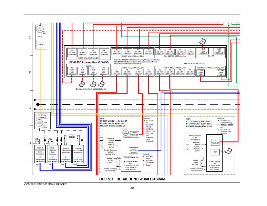
COMPREHENSIVE FINAL REPORT
30
FIGURE 1 DETAIL OF NETWORK DIAGRAM
COMPREHENSIVE FINAL REPORT
31
Network Capabilities
The network was designed to provide 100 megabit fast Ethernet to each end device. Communications
between switches supported Ethernet at a speed of one gigabit. Due to the traffic volume associated
with an IEC 61850 implementation, the network supported MAC address filtering, priority
configuration, and port level VLANs. Each of these items was enabled and configured as required to
ensure timely packet delivery.
Network Security
The test system’s three networks were isolated, having no remote connectivity to other networks. The
network equipment selected for this project was supplied with security features that can be enabled if
necessary.
Test Set Interface
Manufacturers’ test sets had their Ethernet configuration ports connected to the station bus for
engineering programming access. The Ethernet port, on the test set with SV capability, was
temporarily connected to one of the two process bus networks depending on the use case test scenario
testing with SV messages. The station bus interface was used for configuration and monitoring of the
test sets. All test sets were assigned a connection point into the system networks.
Network Tools
The following network tools were used as applicable to monitor the test system environment:
• Freeware network protocol analyzer
• Network monitor using IEC 61850 MMS
• Various manufacturer configuration and event viewing software
• Manufacturer built-in web clients
Station Bus
The station bus was the main substation network that provided the information connectivity between
different process buses, substation systems, and other corporate/enterprise-level systems. For this test
system, the station bus used IEC 61850, GOOSE, and various configuration and diagnostic protocols.
It also provided engineering access to the various protection equipment and test sets for monitoring,
control, and configuration. In addition, this network was connected to an IEEE 1588 PTP master
clock to provide time synchronization to supporting devices.
Process Bus
The process bus networks were isolated from the station bus. The primary purpose of this network
was to transfer information between the equipment MUs and devices requiring the information.
Process Bus #1
Process bus #1 used two managed switches, configured in a star architecture. It supported IEEE 1588
PTP Power Profile, using an isolated connection to the global positioning system (GPS) clock. This
process bus integrated all of the equipment required to demonstrate the use cases for the HS of the
transformer and transformer protection. The HS test cases were:
• Test Case #1 – Breaker Failure Protection (50BF)
• Test Case #2 – Line Differential Protection (87L)
• Test Case #3 – Line Distance and Directional Overcurrent Protection (21 & 50/51)
COMPREHENSIVE FINAL REPORT
32
• Test Case #4 – High Voltage (HV) Bus Overcurrent Differential Protection (87B-50/51)
• Test Case #5 – HV Bus Restrained Current Differential Protection (87B)
• Test Case #6 – HV Bus High Impedance Differential Protection (87B-HIZ)
• Test Case #7 – Transformer Restrained Current Differential Protection (87T)
• Test Case #8 – Transformer Overcurrent Protection (50/51T)
• Test Case #15 – Line Frequency and Voltage (81, 27, and 59)
Process Bus #2
Process bus #2 uses a single managed switch. It supported IEEE 1588 PTP Power Profile, using an
isolated connection to the GPS clock. This process bus integrated all of the equipment required to
demonstrate the use cases for the LS of the transformer. The LS test cases were:
• Test Case #9 – 12kV Bus Partial Overcurrent Differential Protection (87B-51P/G)
• Test Case #10 – 12kV Bus Restrained Current Differential Protection (87B)
• Test Case #11 – Capacitor and Reactor Feeder Overcurrent Protection (50/51)
• Test Case #12 – Capacitor Bank Unbalance Protection (59N)
• Test Case #13 – Reactor Unbalance Protection (51Q)
• Test Case #14 – Reactor and Capacitor Bank VAR Control Automation
Test System Time Synchronization
The synchronization of all devices to a single clock was important in determining performance using
time stamps and the use of SV. For the MUs and their subscribers, synchronized time was a critical
component for publishing and subscribing SV messages. Each end required the same time
synchronization in order to interpret the SV within the same time reference. This test system was
designed to provide a number of time synchronization options that meet the IEC 61850 requirements.
There were four different methods for time synchronization represented in the IEC 61850 standard
that were implemented in this test system: IEEE 1588 PTP; inter-range instrumentation group (IRIG)-
B; simple network time protocol (SNTP); and 1 pulse per second (1PPS). The selected PTP GPS
clock was anticipated to perform all test system time synchronization. This clock provided four
independent network connections that provided PTP and SNTP while leaving the various networks
isolated from each other. It also provided eight programmable 1PPS and IRIG-B outputs. These
different time source options provided support for the varied manufacturer offerings for time
synchronization.
Some devices required fiber optic inputs or it might have been desired that other devices utilize a
fiber link from the GPS clock (to better model a substation with fiber connected devices in the yard).
This test system used two different manufacturer’s solutions to perform this conversion. The first
solution covered equipment that had hardwired inputs on both ends, but required a fiber optic
interface. This interface was used to time synchronize the reactor and capacitor bank P&C devices.
The second interface converted coax to fiber for devices with fiber optic time input from the clock,
which has a hardwired BNC connection.
IEEE 1588 Precision Time Protocol (PTP)
The selected clock provided master PTP clock interfaces for all of its network interfaces. The clock
also supported an IEEE 1588 PC37.238/D16. IEEE Draft Standard Profile for Use of IEEE 1588
Precision Time Protocol in Power System Applications mode of operation. The connections between
the clock and the network switches, that support PTP delivery to the end device, were shown in the
Test Bed Network and Time Synch Diagram included in Appendix C. This test system used the IEEE
COMPREHENSIVE FINAL REPORT
33
PC37.238 power profile for PTP. The selected switches also needed to be IEEE 1588 compliant. A
boundary or transparent clock role was assumed by the switch to successfully deliver IEEE 1588 PTP
Power Profile messages to end devices or other switches.
Inter-Range Instrumentation Group (IRIG-B)
Not all devices supported PTP, but they supported IRIG-B. The test system had an IRIG-B un-
modulated (DC level shift) bus to provide a time source to these units. The test sets were specified
with the IRIG-B input modules to synchronize events and provide time synchronization for SV
messages. The test system utilized IRIGB-004, which has the year information encoded in the
message.
1 Pulse per Second (1PPS)
Some MUs required 1PPS. The IEC 61850 user group’s implementation standard for IEC 61850-9-2
Edition 1, known as IEC 61850-9-2LE, Utility Communications Architecture (UCA) International
Users Group Implementation Guideline for Digital Interface to Instrument Transformers Using IEC
61850-9-2, specifies using 1PPS for MU time synchronization. The test system included fiber optic
transmission equipment for this signal to provide a fiber interface to the MUs. Using this fiber optic
interface mimicked field implementation requirements that place MUs in the substation yard.
Simple Network Time Protocol (SNTP)
There would be two uses for the SNTP method of time synchronization. The first was to time
synchronize the V2M6 MU. This device only has the option to use SNTP for time synchronization.
The second use was for relays V2M1, V2M2, V2M3, and V2M4. These relays required 1PPS inputs
for SV messages. In order to maintain a synchronized time, the station bus interface was connected to
the clocks SNTP server.
IEC 61850 Information Transfer Protocols
One of the main goals of the project was the reduction in substation P&C wiring. To accomplish this,
IEC 61850 protocols were utilized whenever possible.
Manufacturing Message Specification (MMS)
The test system utilized MMS for non-time sensitive communications between individual relays and
between relays and other IEDs, such as programmable automation controllers.
Generic Object Oriented Substation Events (GOOSE)
The test system utilized GOOSE messages for time sensitive communications from MUs to relays,
between relays. This included messages to operate the breaker simulators and provide status changes
to the appropriate relays.
In addition, the test system utilized GOOSE messages to provide volt-ampere reactive (VAR) data
from the simulated HS bus to the reactive automation controllers.
Sampled Value (SV)
The test system utilized SV for ampere and voltage measurement communications between merging
units and relays.
GOOSE and SV Data Flow Spreadsheet
A spreadsheet was developed to identify the message requirements with publishers and subscribers
for both SV and GOOSE messages. Control block parameters were developed during this stage. Both
GOOSE and SV messages require the identification of data sets. Each GOOSE message services a
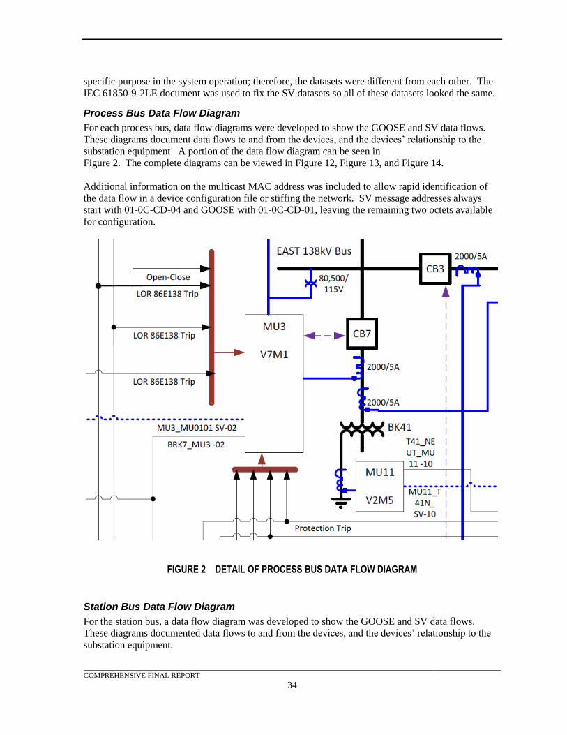
COMPREHENSIVE FINAL REPORT
34
specific purpose in the system operation; therefore, the datasets were different from each other. The
IEC 61850-9-2LE document was used to fix the SV datasets so all of these datasets looked the same.
Process Bus Data Flow Diagram
For each process bus, data flow diagrams were developed to show the GOOSE and SV data flows.
These diagrams document data flows to and from the devices, and the devices’ relationship to the
substation equipment. A portion of the data flow diagram can be seen in
Figure 2. The complete diagrams can be viewed in Figure 12, Figure 13, and Figure 14.
Additional information on the multicast MAC address was included to allow rapid identification of
the data flow in a device configuration file or stiffing the network. SV message addresses always
start with 01-0C-CD-04 and GOOSE with 01-0C-CD-01, leaving the remaining two octets available
for configuration.
FIGURE 2 DETAIL OF PROCESS BUS DATA FLOW DIAGRAM
Station Bus Data Flow Diagram
For the station bus, a data flow diagram was developed to show the GOOSE and SV data flows.
These diagrams documented data flows to and from the devices, and the devices’ relationship to the
substation equipment.
COMPREHENSIVE FINAL REPORT
35
The only function used for the station bus was reactor and capacitor bank control. With the additional
flexibility of GOOSE messaging, the same equipment and control philosophy that was currently used
in the typical reactive control systems was used. A HS relay published the required analog
measurement data to the controllers using GOOSE messaging. GOOSE messaging was also used to
exchange information between the reactive bank protection equipment controllers.
Capacitor and Reactor Bank Automation
Reactor and capacitor bank VAR Control Automation utilized GOOSE analog and digital messaging.
This allowed addition and subtraction of capacitor and/or reactor elements based on VAR flow in/out
of the distribution step-down transformer as measured on the transformer HS connection. This was
accomplished by using the 50/51T relay to measure the VAR flow and then transmit this information
via GOOSE to the two automation controllers where the decision-making logic was configured. To
prevent adding capacitors when reactors were on line and vice versa, interlocking was performed
between the standalone reactor and capacitor bank automation controllers by GOOSE messages. The
imbalance relays were then used to perform a lockout function when appropriate.
High Side (HS) and Low Side (LS) Lockout Relays
The lockout relays reproduced the functions of a traditional hardwired lockout relay scheme. To
emulate lockout relay functions, a virtual lockout-relaying scheme was be developed using latching
variables and close blocking logic within the protection relays. A detailed description of the lockout
relay logic can be found in the Test System Design section.
Interfaces
Test Switches
Each MU was provided with a test switch to enable efficient connection from the test set to the MU.
Test switches accommodated in-service test plugs to minimize re-wiring of the test set leads. Test
switches also limited personnel exposure to energized parts. Test blocks at each MU simulated a real
field installation and provide simplified test set connectivity to the MUs secondary current and
voltage inputs.
IEDs were supplied with fiber ports whenever possible. When available, IEDs were supplied with at
least one copper port. This simplified connection to laptops and other test/monitoring devices.
Device requirements
Relays
The protection equipment had at least one connection to the process bus and at least one connection to
the station bus. All information to and from the substation equipment such as a CT, PT, circuit
breaker, etc., came through the process bus interface. The station bus interface was used for GOOSE
information exchange between process bus bays, SCADA MMS communication, and other uses. The
test system used protection relays from three different manufacturers.
Process Bus Merging Units (MUs)
MUs were connected to the process bus and served as the interface to the substation equipment such
as a CTs, PTs, circuit breaker, etc. These MUs provided the hardwired connection for the CT, PT,
inputs, and output signaling that was digitized over the process bus using IEC 61850 SV and GOOSE.
IEDs that subscribed to this information through their process bus connection also had an independent
Ethernet connection to the station bus in order to move the required data between bays, substation
level systems or corporate/enterprise level systems. These IEDs also published GOOSE messages,
COMPREHENSIVE FINAL REPORT
36
which were subscribed to by the MUs to issue trip, close or other control operations to the equipment.
The test system used merging units from five different manufacturers.
Software
Each IED was supplied with all of the software needed to configure and trouble shoot its
performance.
Ethernet Switch Features
The Ethernet network switches supported the following features:
• Given the expectation for advanced networking features, all switches were managed.
Managed switches allowed for other applications such as security features, MAC filtering,
monitoring, etc.
• Support for port level VLANs, multi-cast filtering, and priority configuration was required.
Both GOOSE and SV uses VLAN and priority in their message headers.
• The switches supported a wide range of media and provide a high port density.
• Most of the network connections used fiber and the connection types were either straight tip
(ST) or LC. There were requirements for engineering access or station bus devices that also
required RJ45 connections so the switch must have a number of options available to adapt to
the project requirements.
• Gigabit switches were important, especially for the process buses, due to the high bandwidth
requirements for SV.
• Each switch was IEEE 1588 compliant and was able to assume a boundary or transparent
clock role to successfully deliver IEEE 1588 PTP Power Profile messages to end devices or
other switches.
Time Clock
There were a wide range of options for receiving time synchronization information. A GPS clock that
can provide all four time synchronization methods listed in the IEC 61850 standard; PTP, Inter-range
Instrumentation Group, 1PPS and SNTP was required. Due to limitations of the manufacturers’
equipment all four methods were ultimately implemented. This clock also maintained network
isolation between each of the process buses and the station bus.
Breaker Simulators
The test system had a means of simulating the circuit breaker operation control and feedback interface
with the MUs. Dual coil latching relays (“ice cube” relays) fulfilled this requirement. The dual coils
allowed for both a trip and close control connection and one of two Form C contacts provided the
position feedback to both the MU and RTDS. Another advantage of these relays was that the contact
operation and release time was approximately 25 milliseconds, which was fairly close to the operating
times for most circuit breakers.
RTDS and COMTRADE
The necessary RTDS model was developed to allow the RTDS to be utilized during testing. An
RTDS was used to develop COMTRADE files that could be used for all testing.
COMPREHENSIVE FINAL REPORT
37
RTDS
The RTDS allowed real-time modeling of power system apparatus including generators, transformers,
transmission lines and power system controls. The RTDS was a combination of specially designed
parallel processing hardware and customized software with detailed, efficient algorithms for
representing power system apparatus.
Closed looped testing of protection systems was achieved by interfacing the analog outputs
representing real-time currents and voltages from the power system to the analog inputs on the
protection system. The outputs from the protection system were connected to the RTDS to provide
control, such as circuit breaker tripping and closing, and to monitor the internal elements in the
protection system. In addition, digital statuses, such as circuit breaker position were routed back to
the protection system digital inputs. Through these connections, the RTDS and the protection system
operated as if connected to an actual power system with all of the dynamics and control actions that
typically occur.
The power system components were configured in a graphical user interface program. The detailed
apparatus models, controls, and input / output (I/O) configuration tools were all included in the
interface program. A detailed model was created that included transmission lines, ideal sources,
series capacitors, generators, transformers, circuit breakers, and instrument transformers. The
apparatus models were very detailed and provide an accurate representation of the power system
response. Figure 3 shows a portion of the model.
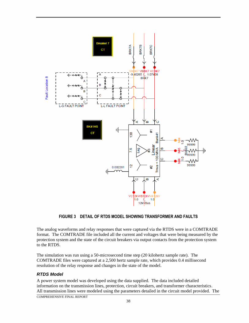
COMPREHENSIVE FINAL REPORT
38
FIGURE 3 DETAIL OF RTDS MODEL SHOWING TRANSFORMER AND FAULTS
The analog waveforms and relay responses that were captured via the RTDS were in a COMTRADE
format. The COMTRADE file included all the current and voltages that were being measured by the
protection system and the state of the circuit breakers via output contacts from the protection system
to the RTDS.
The simulation was run using a 50-microsecond time step (20 kilohertz sample rate). The
COMTRADE files were captured at a 2,500 hertz sample rate, which provides 0.4 millisecond
resolution of the relay response and changes in the state of the model.
RTDS Model
A power system model was developed using the data supplied. The data included detailed
information on the transmission lines, protection, circuit breakers, and transformer characteristics.
All transmission lines were modeled using the parameters detailed in the circuit model provided. The
COMPREHENSIVE FINAL REPORT
39
system model was loosely based on an existing substation and included one 138 kV bus, one
transmission line, one transformer bank, a 12 kV bus, a 12 kV capacitor bank, and a 12 kV reactor
bank.
Equivalent source impedances were calculated at each bus using the Network Boundary Equivalent
function in the protection database provided. An additional transmission line was included to
represent the equivalent transfer impedance between the two substations due to the interconnected
nature of the surrounding system. The sources at each bus were modeled as ideal sources. This
baseline model allowed modifications, during testing, to accommodate frequency deviation test,
voltage deviation tests, and simulation of alternate source impedances.
COMTRADE FILES
The RTDS system produces low-level analog signals that can be output to an external device under
test. In order to get true secondary currents and voltages (5 A or 120 V) an amplifier was required.
For testing at the contractor’s lab, the results of each RTDS simulation was saved in the
COMTRADE format and downloaded into a relay test set, then output to the merging units at
secondary current and voltage levels.
Balanced and unbalanced faults were simulated at eight different fault locations (FLTn). For each
fault location the current through all 138 kV and 12 kV breakers in the simulation, as well as the
138 kV and 12 kV potentials were saved in COMTRADE format. This arrangement allowed the test
sets to output any current, voltage, or combination of the two to all merging units that were under test.
A detail of the RTDS model showing the transformer and faults can be seen in Figure 4. The full
diagram depicting the complete system and the specific location of each fault (FLT1, FLT2, etc.) is in
Appendix B.
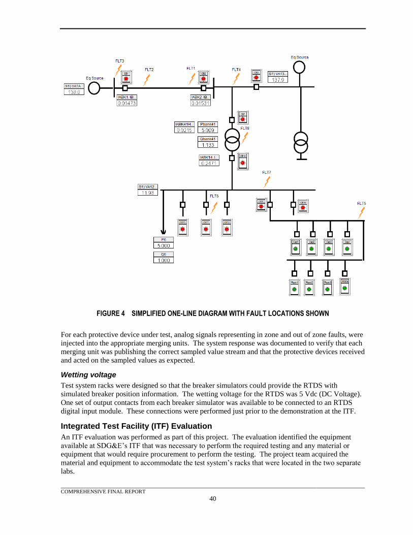
COMPREHENSIVE FINAL REPORT
40
FIGURE 4 SIMPLIFIED ONE-LINE DIAGRAM WITH FAULT LOCATIONS SHOWN
For each protective device under test, analog signals representing in zone and out of zone faults, were
injected into the appropriate merging units. The system response was documented to verify that each
merging unit was publishing the correct sampled value stream and that the protective devices received
and acted on the sampled values as expected.
Wetting voltage
Test system racks were designed so that the breaker simulators could provide the RTDS with
simulated breaker position information. The wetting voltage for the RTDS was 5 Vdc (DC Voltage).
One set of output contacts from each breaker simulator was available to be connected to an RTDS
digital input module. These connections were performed just prior to the demonstration at the ITF.
Integrated Test Facility (ITF) Evaluation
An ITF evaluation was performed as part of this project. The evaluation identified the equipment
available at SDG&E’s ITF that was necessary to perform the required testing and any material or
equipment that would require procurement to perform the testing. The project team acquired the
material and equipment to accommodate the test system’s racks that were located in the two separate
labs.
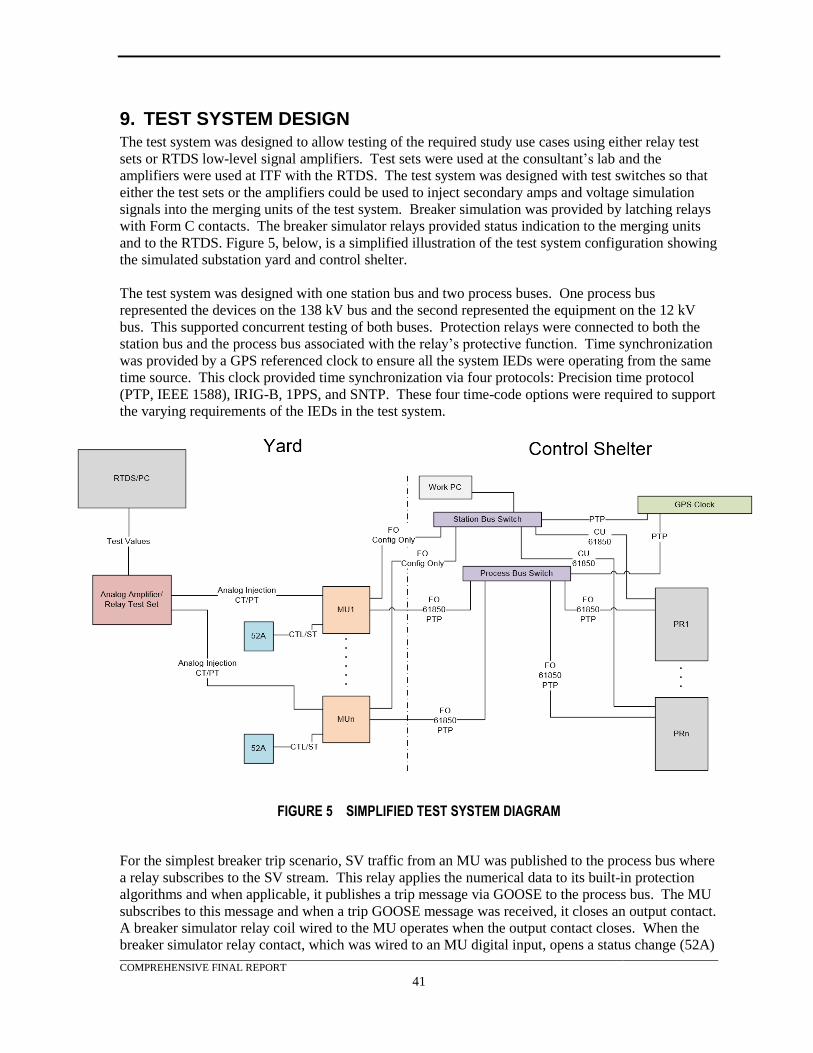
COMPREHENSIVE FINAL REPORT
41
9. TEST SYSTEM DESIGN The test system was designed to allow testing of the required study use cases using either relay test
sets or RTDS low-level signal amplifiers. Test sets were used at the consultant’s lab and the
amplifiers were used at ITF with the RTDS. The test system was designed with test switches so that
either the test sets or the amplifiers could be used to inject secondary amps and voltage simulation
signals into the merging units of the test system. Breaker simulation was provided by latching relays
with Form C contacts. The breaker simulator relays provided status indication to the merging units
and to the RTDS. Figure 5, below, is a simplified illustration of the test system configuration showing
the simulated substation yard and control shelter.
The test system was designed with one station bus and two process buses. One process bus
represented the devices on the 138 kV bus and the second represented the equipment on the 12 kV
bus. This supported concurrent testing of both buses. Protection relays were connected to both the
station bus and the process bus associated with the relay’s protective function. Time synchronization
was provided by a GPS referenced clock to ensure all the system IEDs were operating from the same
time source. This clock provided time synchronization via four protocols: Precision time protocol
(PTP, IEEE 1588), IRIG-B, 1PPS, and SNTP. These four time-code options were required to support
the varying requirements of the IEDs in the test system.
FIGURE 5 SIMPLIFIED TEST SYSTEM DIAGRAM
For the simplest breaker trip scenario, SV traffic from an MU was published to the process bus where
a relay subscribes to the SV stream. This relay applies the numerical data to its built-in protection
algorithms and when applicable, it publishes a trip message via GOOSE to the process bus. The MU
subscribes to this message and when a trip GOOSE message was received, it closes an output contact.
A breaker simulator relay coil wired to the MU operates when the output contact closes. When the
breaker simulator relay contact, which was wired to an MU digital input, opens a status change (52A)
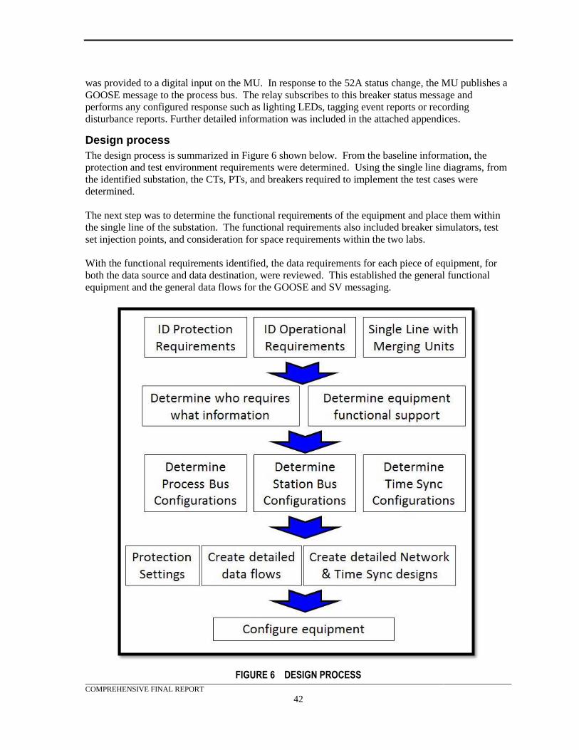
COMPREHENSIVE FINAL REPORT
42
was provided to a digital input on the MU. In response to the 52A status change, the MU publishes a
GOOSE message to the process bus. The relay subscribes to this breaker status message and
performs any configured response such as lighting LEDs, tagging event reports or recording
disturbance reports. Further detailed information was included in the attached appendices.
Design process
The design process is summarized in Figure 6 shown below. From the baseline information, the
protection and test environment requirements were determined. Using the single line diagrams, from
the identified substation, the CTs, PTs, and breakers required to implement the test cases were
determined.
The next step was to determine the functional requirements of the equipment and place them within
the single line of the substation. The functional requirements also included breaker simulators, test
set injection points, and consideration for space requirements within the two labs.
With the functional requirements identified, the data requirements for each piece of equipment, for
both the data source and data destination, were reviewed. This established the general functional
equipment and the general data flows for the GOOSE and SV messaging.
FIGURE 6 DESIGN PROCESS
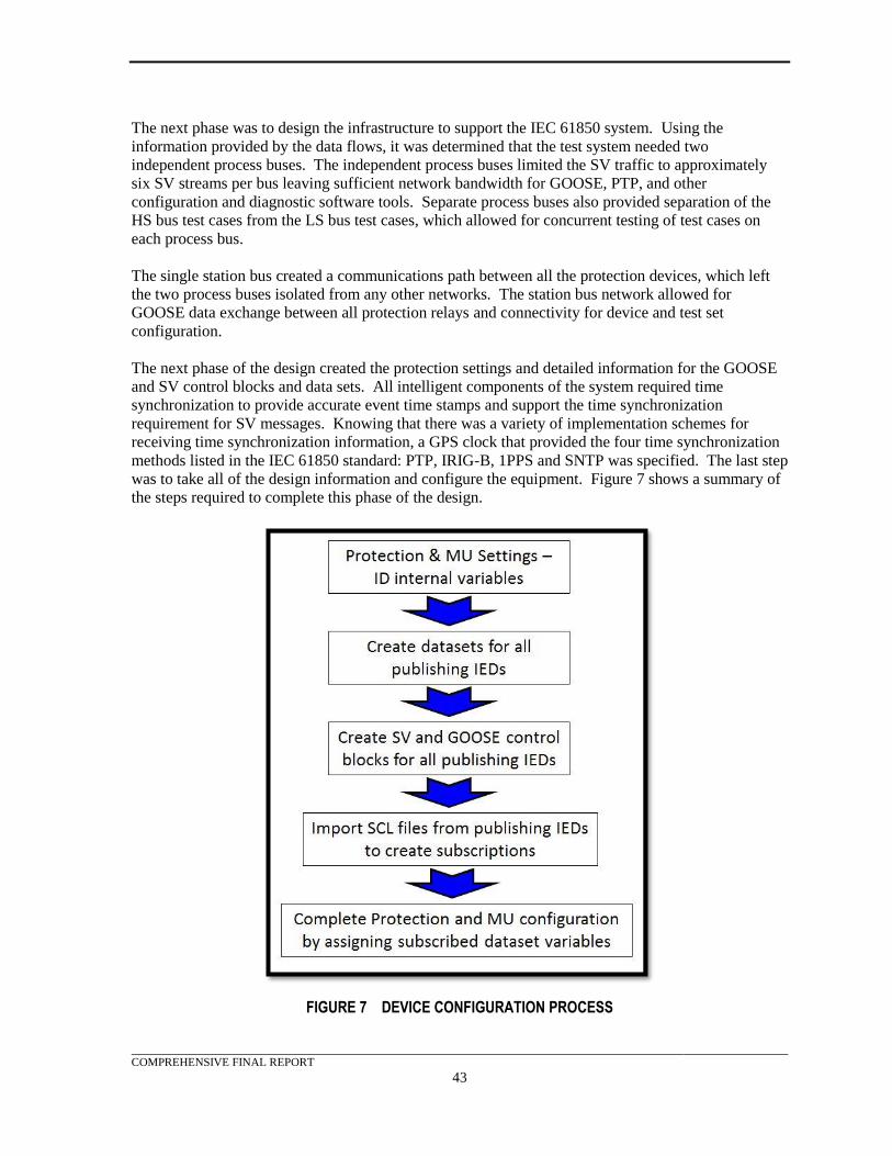
COMPREHENSIVE FINAL REPORT
43
The next phase was to design the infrastructure to support the IEC 61850 system. Using the
information provided by the data flows, it was determined that the test system needed two
independent process buses. The independent process buses limited the SV traffic to approximately
six SV streams per bus leaving sufficient network bandwidth for GOOSE, PTP, and other
configuration and diagnostic software tools. Separate process buses also provided separation of the
HS bus test cases from the LS bus test cases, which allowed for concurrent testing of test cases on
each process bus.
The single station bus created a communications path between all the protection devices, which left
the two process buses isolated from any other networks. The station bus network allowed for
GOOSE data exchange between all protection relays and connectivity for device and test set
configuration.
The next phase of the design created the protection settings and detailed information for the GOOSE
and SV control blocks and data sets. All intelligent components of the system required time
synchronization to provide accurate event time stamps and support the time synchronization
requirement for SV messages. Knowing that there was a variety of implementation schemes for
receiving time synchronization information, a GPS clock that provided the four time synchronization
methods listed in the IEC 61850 standard: PTP, IRIG-B, 1PPS and SNTP was specified. The last step
was to take all of the design information and configure the equipment. Figure 7 shows a summary of
the steps required to complete this phase of the design.
FIGURE 7 DEVICE CONFIGURATION PROCESS
COMPREHENSIVE FINAL REPORT
44
The first step in this process was to determine which internal device data points were used for each
functional data exchange. For each of these internal data points, there was an IEC 61850 substation
configuration language (SCL), logical node data attribute was assigned for transporting GOOSE
messages. For SV messages, all of the manufacturers claimed to support the IEC 61850-9-2LE
implementation which, if true, would fix the SV data set. This information was then entered into the
detailed data flow tables which were used for configuring the data sets in the test system equipment.
After the data sets were created, the detailed data flow tables were used to create the GOOSE and SV
control blocks. Within these control blocks the multicast MAC address, AppID and GOOSE - SV
identification (ID) were assigned. At this stage, all published GOOSE and SV messages could be
configured.
The next step was to configure all of the required subscriptions. To do this each manufacturer’s
configuration software tool outputted a device IEC 61850 IED (intelligent electrical device)
capability description (ICD), instantiated IED description (IID), configured IED description (CID), or
system configuration description (SCD) file. These files contained all the available data set GOOSE
and SV information for a device to subscribe to them. The files were then imported into the
manufacturer configuration software tool where the subscribing device and specific data points within
the message data set were linked to the devices internal points. Once this was done all of the “virtual
wires”, published messages, and subscription messages, were completed. Information exchanges
were then linked from merging units to protection relays and from protection relay to protection relay.
The last step was to configure the devices using this information to fulfill its primary role as defined
in the test cases. The following sections explain in greater detail for each of the major phases of the
design process.
Material Identification and Procurement
Running in parallel to the design process, and using key information from it, was the equipment
vendor selection process. Due to the project’s aggressive schedule, manufacturers with significant
presence in the United Sates were investigated. In addition, compliance with the following guidelines
was required:
• All potential products were required to use a non-proprietary implementation of IEC 61850
MMS, GOOSE, and SV.
• Interoperability, with other manufacturers’ products, was a requirement.
• All potential products were required to be commercially available during the project.
The project team identified four relay and merging unit manufacturers. A third party MU
manufacturer was also identified. Requests for Information were then developed and in-person
interviews with the four identified relay manufacturers were conducted. The interviews included a
manufacturer presentation and time for questions and answers. The project team worked with the
manufacturers to identify the necessary products and develop the required part numbers.
In order to investigate interoperability, the project required a minimum of two manufacturers for each
use case whenever possible. Discussions with the manufacturers were required to identify the
necessary relays, merging units, GPS clock, switches and ancillary equipment/materials. The
information obtained from these efforts was used to guide the part number development.
COMPREHENSIVE FINAL REPORT
45
Before relay test set procurement could begin, the project team determined the capabilities at the ITF
and the available features from the manufacturers. Since the tests would inject currents and voltages
from a traditional relay test set and the ITF testing would utilize an RTDS, a single SV test set was
determined to be sufficient. At the end of the process, the use of rental test sets was identified to
minimize costs. The total number of test sets was determined to allow concurrent testing of several of
the use cases described above.
Procurement of the materials and test sets was a joint effort between the project team parties. All
purchased materials and equipment were shipped to the contractor’s office.
Preliminary Design Process
The preliminary design focused on the requirements to perform the test cases listed in the Test Cases
section of this document. Using the single line prints for the identified substation specific protection
devices, CTs, PTs and circuits were selected for the tests. The identified substation did not deploy
backup protection schemes, but for the purpose of including multiple manufacturers in the testing,
backup schemes were deployed. A means of simulating circuit breaker operation control and
feedback interface with the MU was also required. Dual coil latching relays (“ice cube” relays)
fulfilled this requirement. The dual coils allowed for both a trip and close control connection and the
two form C contacts provided position feedback to both the MU and RTDS. The contact operation
and release time of 25 milliseconds (ms) was fairly close to the operating times for most circuit
breakers. Test blocks at each MU to both simulate a real field installation and provide easy test set
connectivity to the MUs secondary current and voltage inputs were included.
From the baseline, methods for implementing the use cases and their protection requirements were
known. The goal was to implement test cases using IEC 61850 and some of its supporting standards.
To do this every CT and PT required a MU to replace the traditional CT and PT wiring with
published IEC 61850 SV messages. Each circuit breaker required supervision from a MU. From the
baseline study the data requirements for each of the protection relays and which breakers they would
trip during a protection event were known.
In order to provide a clearer picture of all the publication and subscription requirements between
devices and MUs the spreadsheet in Appendix D was created. Figure 8 shows the structure of the
matrix. The left hand side lists the protection relays at the top followed by the merging units at the
bottom. Along the top were the CT and PT equipment followed by the circuit breakers required to
provide the protection relays with the information and controls needed to perform their operations.
The matrix identified which MU was connected to which CT and PT. It also identified which MU
provided the trip/close controls and position feedback for each of the various circuit breakers. Finally
for each of the protection relays the matrix identified what CT and PT information they required and
which circuit breakers they needed to control.
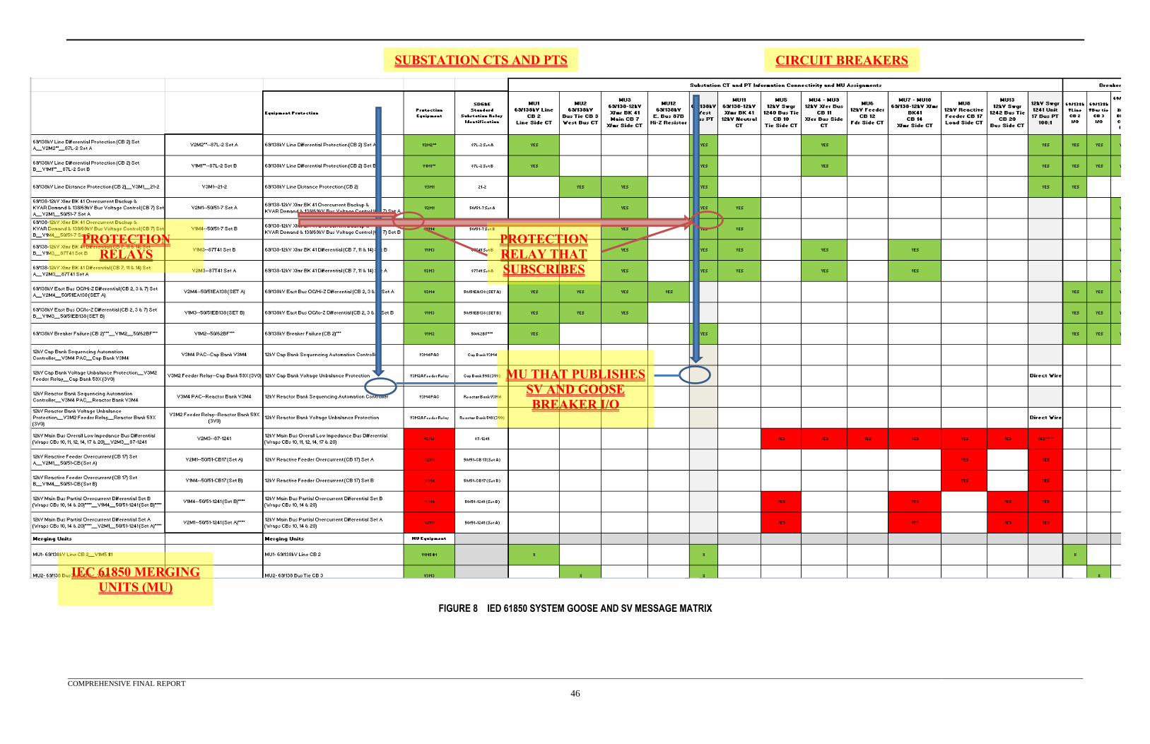
COMPREHENSIVE FINAL REPORT
46
FIGURE 8 IED 61850 SYSTEM GOOSE AND SV MESSAGE MATRIX
SUBSTATION CTS AND PTS CIRCUIT BREAKERS
PROTECTION
RELAYS
IEC 61850 MERGING
UNITS (MU)
MU THAT PUBLISHES
SV AND GOOSE
BREAKER I/O
PROTECTION
RELAY THAT
SUBSCRIBES
COMPREHENSIVE FINAL REPORT
47
Once the matrix was completed, the subscriptions for each protection relay from each of the MUs for
published SV and GOOSE messages were available. These data flows provided the protection relays
with the secondary current and voltage samples needed to perform their protection functions and
status indication of the circuit breakers’ position. Working in reverse this matrix also defined which
MUs needed to subscribe to the published GOOSE messages from the protection relays, which
execute the trip actions. Additionally the matrix provided a clear overview of the data flow
segregation between devices such that the network traffic could be isolated into separate process
buses. Two process buses were identified and color coded in the matrix using GREEN for process
bus #1 and RED for process bus #2.
One of the testing goals was to digitize the test case implementation including lock out relays. With
the matrix completed, identification of which protection relays initiate the lock out and which of the
protection relays house the digital lock out logic could be determined. Once the lock out logic within
this relay was set, the only means to reset it was through a physical interface with the relay’s front
panel pushbuttons.
The use cases did not include any SCADA operations, but in order to demonstrate the lock out
operation one protection relay, that would be the SCADA control interface for the circuit breakers
within a process bus, was selected. This logic required additional data flows (published data and
subscriptions) for initiating lock outs and blocking circuit breaker close commands.
Figure 9 shows the lock out and SCADA supervisory device information added to the matrix. Using
the base line information, identified substation single line, and the data flows developed from the MU
matrix, there was enough information to develop a preliminary design. This design included a
network diagram, data flow tables and protection criteria.
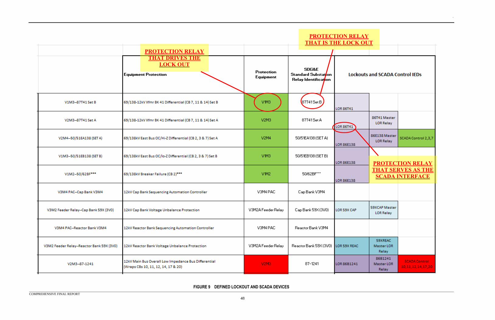
.
COMPREHENSIVE FINAL REPORT
48
FIGURE 9 DEFINED LOCKOUT AND SCADA DEVICES
PROTECTION RELAY
THAT DRIVES THE
LOCK OUT
PROTECTION RELAY
THAT IS THE LOCK OUT
PROTECTION RELAY
THAT SERVES AS THE
SCADA INTERFACE
.
COMPREHENSIVE FINAL REPORT
49
Test System Network
The equipment and design for the test system network and time synchronization provided a flexible
infrastructure to support functions for an IEC 61850 environment. The design provided various
network medium connection options and different methods for time synchronization per the IEC
61850 standard to support the various equipment used in this test system. Specifically, the test
system infrastructure must demonstrate fiber solutions, which will be required between equipment
located in the substation yard and substation control shelter via the process bus.
There were many different manufacturers that could provide equipment and fulfill the requirements
for this test system. Manufacturer selection included previous experience with the product,
discussion with product manufacturers, providing a multi-vendor test environment, and the products’
specifications to meet the requirements for the test system.
The diagram shown in Appendix C was the test system network and time synchronization connection
diagram. The intent of this diagram was to show the various equipment capabilities and provide a
means for documenting the different use case scenario configurations.
Each network port used in this test system was assigned an IP address that was associated with the
network to which it was connected. Some of these ports were required for testing and some were
required for point to point connection for access. In some cases the network connection ports did not
support transmission control protocol (TCP) /IP. These ports only provided a, non-routable, layer 2
MAC interface for GOOSE and SV messaging.
There were some devices that did not support both GOOSE and SV messages on the same port.
These devices had two separate network connections to the process bus.
Station Bus
The station bus was the main substation network that provided the information connectivity between
different process buses, substation systems and enterprise systems. For this test system the station
bus used IEC 61850, GOOSE and various configuration and diagnostic protocols. It also provided
engineering access to the various protection equipment and test sets for monitoring, control and
configuration. In addition, this network was connected to an IEEE 1588 PTP master clock to provide
time synchronization to supporting devices.
The station bus was the communications conduit for device-to-device GOOSE messages allowing for
the transfer of information between isolated process bus networks. IEC 61850 MMS was used to
access SCADA, configuration and health information from the various devices. It was also used to
test the system supervisory control close blocking by the digital lockouts.
Managed switches made up the station bus. These switches had a mixture of copper RJ45 and
multimode fiber connections to accommodate the different manufacturer connectivity options. All
network traffic used virtual local area network #1.
Process Bus
Each process bus was designed as a separate network that was isolated from the station bus and the
other process bus network. The primary purpose of this network was to transfer information between
the equipment MUs and devices requiring the information. MUs typically had only a single process
bus interface vs. protection relays that had independent process bus and station bus interfaces. Some
manufacturers’ protection relays provided independent process bus interfaces, with one only
.
COMPREHENSIVE FINAL REPORT
50
supporting SV messages and the other only supporting GOOSE. Other manufacturers’ MUs provided
independent station bus interfaces.
The test system used both IEC 61850 SV and IEC 61850 GOOSE protocols. The process buses were
also connected to an IEEE 1588 PTP master clock to provide time synchronization to supporting
devices. The test system equipment had fiber optic options to emulate real world solutions that would
be deployed in the field. The network diagram indicated the demarcation between the substation yard
equipment and the substation control shelter equipment with a dashed line. All communications paths
crossing this line used fiber optics, which would be the communications medium of choice for
process bus connectivity.
There were two independent process bus networks designed into the test system to accommodate
different test case scenarios divided between the high side and low side of the transformer. Each
process bus had at least four engineering access ports to be used for monitoring and device
configuration. The network and its equipment were designed to allow concurrent test case testing on
both process bus #1 and #2. All network traffic used virtual local area network #1.
Process Bus #1
Process bus #1 used two managed switches. It was configured in a star design without using high-
availability seamless redundancy (HSR) or parallel redundancy protocol (PRP). This process bus
integrated all of the equipment required to demonstrate the test cases for the high side of the
transformer and transformer protection. It supported IEEE 1588 PTP Power Profile, using an isolated
connection to the GPS clock.
Some of the devices connected to the network did not manage all the SV and GOOSE traffic. When
some devices dropped packets due to a central processing unit (CPU) overload condition, static MAC
filtering on some of the ports was deployed. This solved problems and relieved the affected device of
the additional burden on parsing all the messages.
Process Bus #2
Process bus #2 was a single managed switch. It was configured in a star design without using HSR or
PRP. It supported IEEE 1588 PTP Power Profile, with an isolated connection to the GPS clock. This
process bus integrated all of the equipment required to demonstrate the test cases for the low side of
the transformer.
To prevent the same dropped packet problem, seen on process bus #1, static MAC filtering, as used
on process bus #1, was deployed.
Test Set Interface
Each test set was connected via Ethernet to the station bus for engineering programming access. The
SV capable test set’s Ethernet port was temporarily connected to one of the two process bus networks,
depending on the SV message needs of the test case scenario. The station bus interface was used for
configuration and monitoring of the test sets. All test sets were assigned a connection point into the
system networks.
Test System Time Synchronization
All devices were time synchronized to a single clock to allow verification of performance using time
stamps and the use of SV. For the MUs and their subscribers, synchronized time was a critical
component for publishing and subscribing SV messages. Each end required the same time
synchronization in order to interpret the SV within the same time reference. This test system was
designed to provide a number of time synchronization options that met the IEC 61850 requirements.
.
COMPREHENSIVE FINAL REPORT
51
The selected clock supported four independent network connections to provide PTP and SNTP while
leaving the various networks isolated from each other. It also provided eight programmable 1PPS
and IRIG-B outputs. These different time source options provided support for the varied
manufacturer offerings for time synchronization.
In order to maintain the test system’s scheme for fiber optic cabling between the MU racks and
switch/relay racks, fiber was required. Some devices, however only provided support for copper time
signals. When a device required a fiber optic input, or the device required a fiber link directly from
the GPS Clock, the test system used two different manufacturer solutions to perform this conversion.
The first solution covered equipment on both ends that had hardwired inputs but required fiber optic
cabling between the clock and the end device. V8M1 and V8M2 were used to support the copper
inputs and provide a fiber channel between the two sets of racks. This interface was used to time
synchronize the reactor and capacitor bank P&C devices. The second interface covered devices that
required fiber optic time input from the clock’s copper output. A V8M1 fiber convertor was used for
this interface.
IEEE 1588 PTP
The PTP connections included the connections between the clock and the network switches to support
PTP delivery to the end device. This test system used the IEEE PC37.238 power profile for PTP.
The following PTP configuration parameters were used:
V3M5 Clock:
• The clock identification was 10
• Power Profile (Layer 2)
• 1 step
• Station bus domain 0, process bus #1 domain 1 and process bus #2 domain 2
Ethernet Switches:
• Power Profile (Layer 2)
• 1 step
• Domain as the network requires
• Transparent Clock
• All ports enabled
• MAC filtering enabled as required per port
The following equipment was configured to use PTP:
• V3M1 and V3M3
• V7M1
• V6M1
• V1M1, V1M2, V1M3, V1M4
• V2M5
• All network Ethernet switches
IRIG-B
For the devices that did not support PTP but supported IRIG-B, the test system used an IRIG-B
unmodulated (DC level shift) signal to provide a time source. In addition, the relay test sets were
specified with the IRIG-B input modules to synchronize events and provide time synchronization for
the V10M1’s SV messages. IRIG-B-004 was used to include the year information in the message.
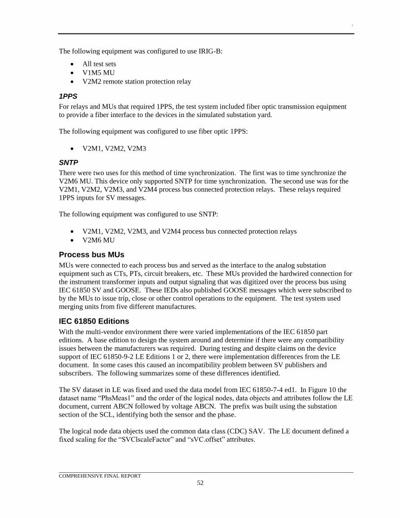
.
COMPREHENSIVE FINAL REPORT
52
The following equipment was configured to use IRIG-B:
• All test sets
• V1M5 MU
• V2M2 remote station protection relay
1PPS
For relays and MUs that required 1PPS, the test system included fiber optic transmission equipment
to provide a fiber interface to the devices in the simulated substation yard.
The following equipment was configured to use fiber optic 1PPS:
• V2M1, V2M2, V2M3
SNTP
There were two uses for this method of time synchronization. The first was to time synchronize the
V2M6 MU. This device only supported SNTP for time synchronization. The second use was for the
V2M1, V2M2, V2M3, and V2M4 process bus connected protection relays. These relays required
1PPS inputs for SV messages.
The following equipment was configured to use SNTP:
• V2M1, V2M2, V2M3, and V2M4 process bus connected protection relays
• V2M6 MU
Process bus MUs
MUs were connected to each process bus and served as the interface to the analog substation
equipment such as CTs, PTs, circuit breakers, etc. These MUs provided the hardwired connection for
the instrument transformer inputs and output signaling that was digitized over the process bus using
IEC 61850 SV and GOOSE. These IEDs also published GOOSE messages which were subscribed to
by the MUs to issue trip, close or other control operations to the equipment. The test system used
merging units from five different manufactures.
IEC 61850 Editions
With the multi-vendor environment there were varied implementations of the IEC 61850 part
editions. A base edition to design the system around and determine if there were any compatibility
issues between the manufacturers was required. During testing and despite claims on the device
support of IEC 61850-9-2 LE Editions 1 or 2, there were implementation differences from the LE
document. In some cases this caused an incompatibility problem between SV publishers and
subscribers. The following summarizes some of these differences identified.
The SV dataset in LE was fixed and used the data model from IEC 61850-7-4 ed1. In Figure 10 the
dataset name “PhsMeas1” and the order of the logical nodes, data objects and attributes follow the LE
document, current ABCN followed by voltage ABCN. The prefix was built using the substation
section of the SCL, identifying both the sensor and the phase.
The logical node data objects used the common data class (CDC) SAV. The LE document defined a
fixed scaling for the “SVClscaleFactor” and “sVC.offset” attributes.
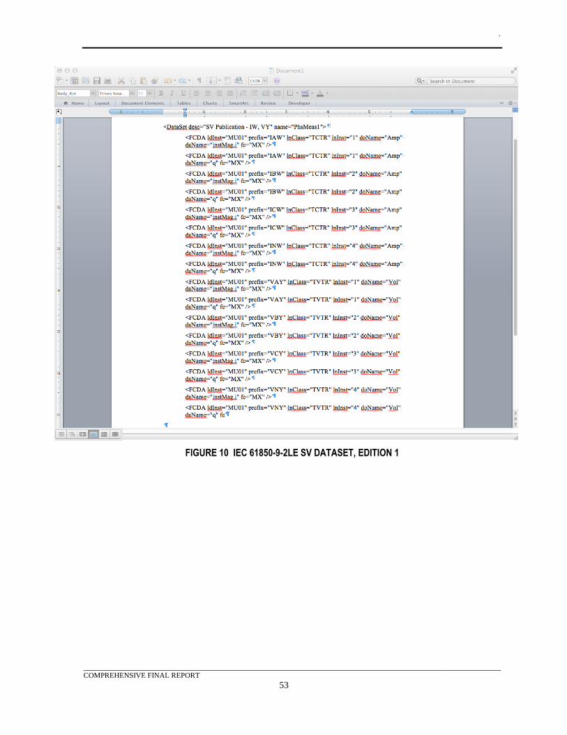
.
COMPREHENSIVE FINAL REPORT
53
FIGURE 10 IEC 61850-9-2LE SV DATASET, EDITION 1
.
COMPREHENSIVE FINAL REPORT
54
In edition 2, the “doName” was changed for the logical nodes as follows
• “TVTR” was changed to “TCTR”
• ”Amp” was changed to “AmpSv”
• “Vol” was changed to “VolSv”
Figure 11 shows the model for a different LE merging unit, which has the order and dataset naming
correct but has implemented the edition 2 changes to the model.
FIGURE 11 IEC 61850-9-2 SV DATASET, EDITION 2
Some of the merging units which were set to publish the LE streams sent the edition 2 model vs. the
edition 1 model. Examples of this included:
• Clock source in LE was to be 1PPS but most devices did not accept 1PPS taking in its place
either or both were IRIG-B or IEEE 1588. There were a number of LE publishers and
subscribers which only used IRIG-B or IEEE 1588 for time synchronization.
.
COMPREHENSIVE FINAL REPORT
55
• The SV control block in all cases matched the edition 1 requirements for LE. Some
manufacturers allowed the users to select and de-select control block options to provide
additional support for edition 2 SV streams. The multicast sampled value control block
(MSVCB) for edition 1 had the following structure (taken from IEC 61850-7-4 Edition 1
2004-04):
MsvCBNam ObjectName
MsvCBRef ObjectReference
SvEna Boolean
MsvID Visible-string
DatSet ObjectReference
ConfRev Integer
SmpRate Integer
OptFlds
refresh-time Boolean
sample synchronized Boolean
sample-rate Boolean
The LE document fixed the value for some of these fields. For the protection profile which was used
in testing, the SmpRate should be 80; OptFlds: refresh-time could be true or false; sample-
synchronized should be true; and sample-rate should be false. The svID and dataset naming
conventions were defined.
The SV message buffer was also defined in the LE document but some differences in implementation
were identified. The edition 1 message buffer format, minus the header format, was structured as
follows (taken from IEC 61850-7-4 Edition 1 2004-04):
• MsvID or UsvID - Should be a system-wide unique identification.
• DatSet- ObjectReference datset OPTIONAL. The value was from the MSVCB.
• SmpCnt- Will be incremented each time a new sampling value was taken. The counter shall
be set to zero if the sampling was synchronized by clock signal (SmpSynch = TRUE) and the
synchronizing signal occurs. When sync pulses were used to synchronize merging units, the
counter shall be set to zero with every sync pulse. The value 0 shall be given to the data set
where the sampling of the primary current coincides with the sync pulse.
• ConfRev- The value was from the MSVCB.
• RefrTm contains the refresh time of the SV buffer. OPTIONAL
• SmpSynch- BOOLEAN value, TRUE = SV are synchronized by a clock signal. FALSE = SV
are not synchronized.
• SmpRate- The value was from the MSVCB.
• Sample [1..n] Type depends on the common data class defined in IEC 61850-7-3.
The LE document also defined the message buffer format as having the svID, smpCnt, confRev,
smpSynch and the data (samples). The OPTIONAL DatSet and RefrTm were not included. The LE
stated that as long as the merging unit was time synchronized the “SmpSynch” should be set to TRUE
(Boolean). The SmpCnt should behave as specified in IEC 61850-7-2 Edition 1.
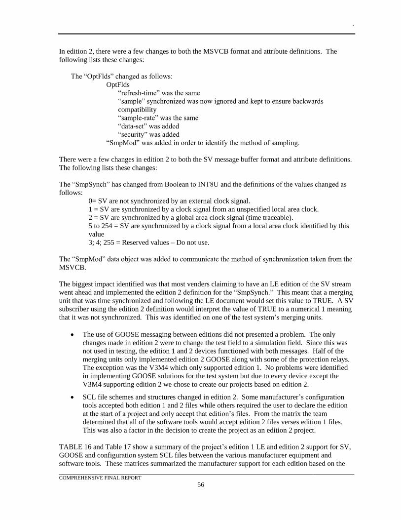
.
COMPREHENSIVE FINAL REPORT
56
In edition 2, there were a few changes to both the MSVCB format and attribute definitions. The
following lists these changes:
The “OptFlds” changed as follows:
OptFlds
“refresh-time” was the same
“sample” synchronized was now ignored and kept to ensure backwards
compatibility
“sample-rate” was the same
“data-set” was added
“security” was added
“SmpMod” was added in order to identify the method of sampling.
There were a few changes in edition 2 to both the SV message buffer format and attribute definitions.
The following lists these changes:
The “SmpSynch” has changed from Boolean to INT8U and the definitions of the values changed as
follows:
0= SV are not synchronized by an external clock signal.
1 = SV are synchronized by a clock signal from an unspecified local area clock.
2 = SV are synchronized by a global area clock signal (time traceable).
5 to 254 = SV are synchronized by a clock signal from a local area clock identified by this
value
3; 4; 255 = Reserved values – Do not use.
The “SmpMod” data object was added to communicate the method of synchronization taken from the
MSVCB.
The biggest impact identified was that most venders claiming to have an LE edition of the SV stream
went ahead and implemented the edition 2 definition for the “SmpSynch.” This meant that a merging
unit that was time synchronized and following the LE document would set this value to TRUE. A SV
subscriber using the edition 2 definition would interpret the value of TRUE to a numerical 1 meaning
that it was not synchronized. This was identified on one of the test system’s merging units.
• The use of GOOSE messaging between editions did not presented a problem. The only
changes made in edition 2 were to change the test field to a simulation field. Since this was
not used in testing, the edition 1 and 2 devices functioned with both messages. Half of the
merging units only implemented edition 2 GOOSE along with some of the protection relays.
The exception was the V3M4 which only supported edition 1. No problems were identified
in implementing GOOSE solutions for the test system but due to every device except the
V3M4 supporting edition 2 we chose to create our projects based on edition 2.
• SCL file schemes and structures changed in edition 2. Some manufacturer’s configuration
tools accepted both edition 1 and 2 files while others required the user to declare the edition
at the start of a project and only accept that edition’s files. From the matrix the team
determined that all of the software tools would accept edition 2 files verses edition 1 files.
This was also a factor in the decision to create the project as an edition 2 project.
TABLE 16 and Table 17 show a summary of the project’s edition 1 LE and edition 2 support for SV,
GOOSE and configuration system SCL files between the various manufacturer equipment and
software tools. These matrices summarized the manufacturer support for each edition based on the
.
COMPREHENSIVE FINAL REPORT
57
option codes selected at the time of purchase. Options may be available to revise the assessments, in
these figures, but the listed results were specific to the products selected for this project. In many
cases the manufacturers support exceeded the requirements of the specific edition even when strict
compliance was not identified.
.
COMPREHENSIVE FINAL REPORT
58
TABLE 16 PROTECTION DEVICE IEC 61850 EDITION MATRIX
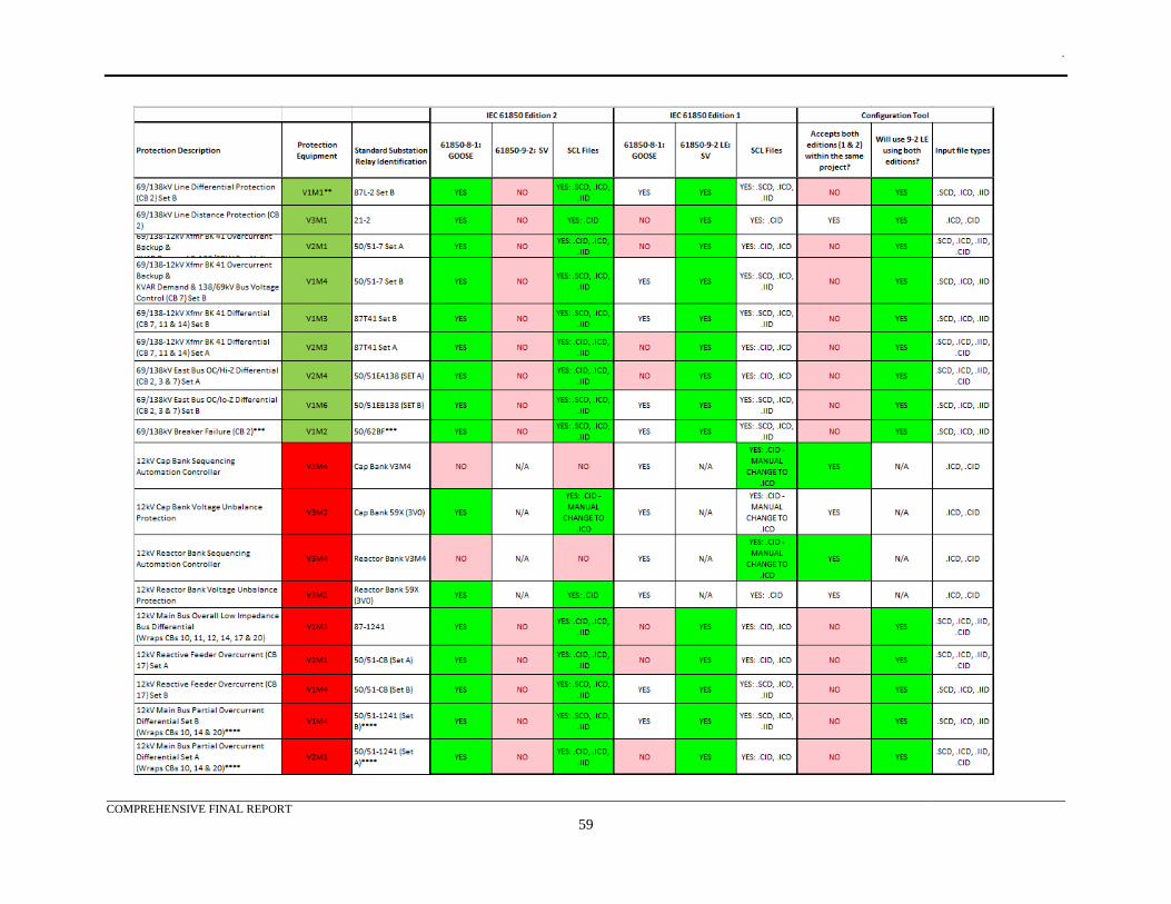
.
COMPREHENSIVE FINAL REPORT
59
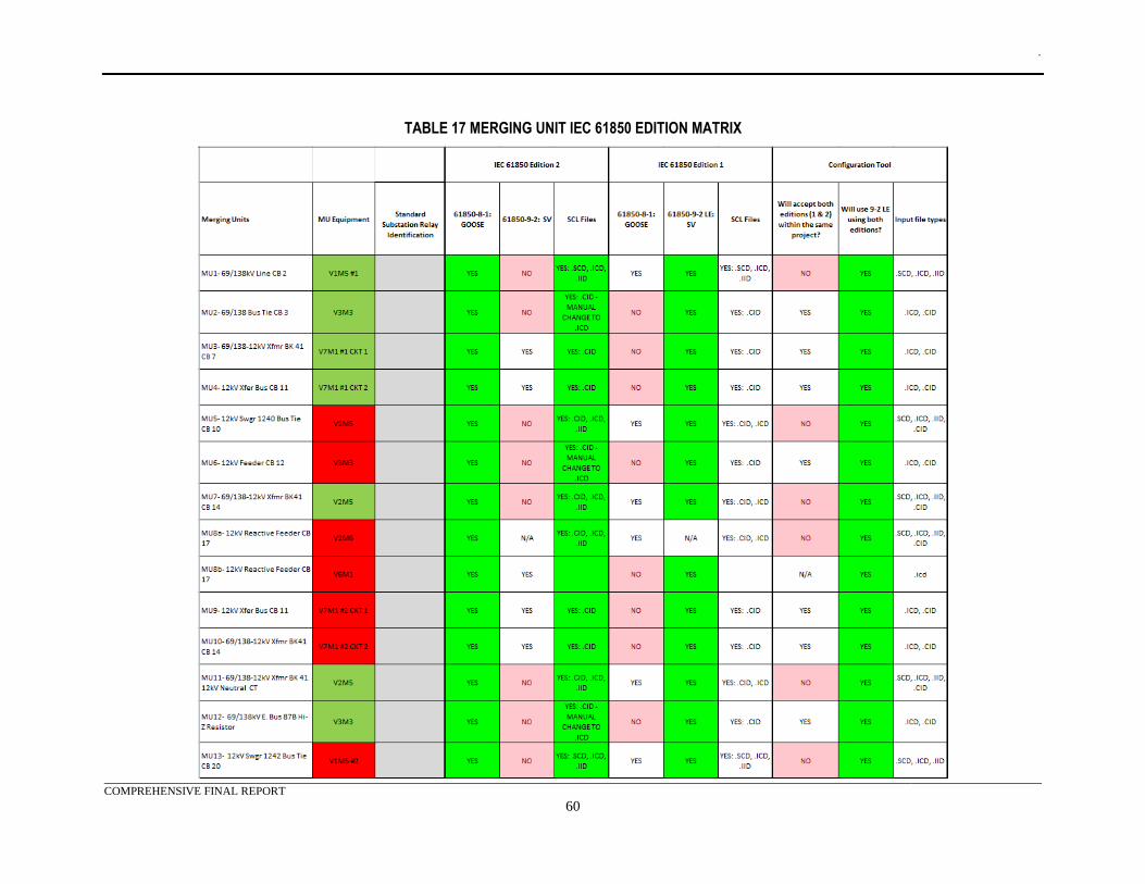
.
COMPREHENSIVE FINAL REPORT
60
TABLE 17 MERGING UNIT IEC 61850 EDITION MATRIX
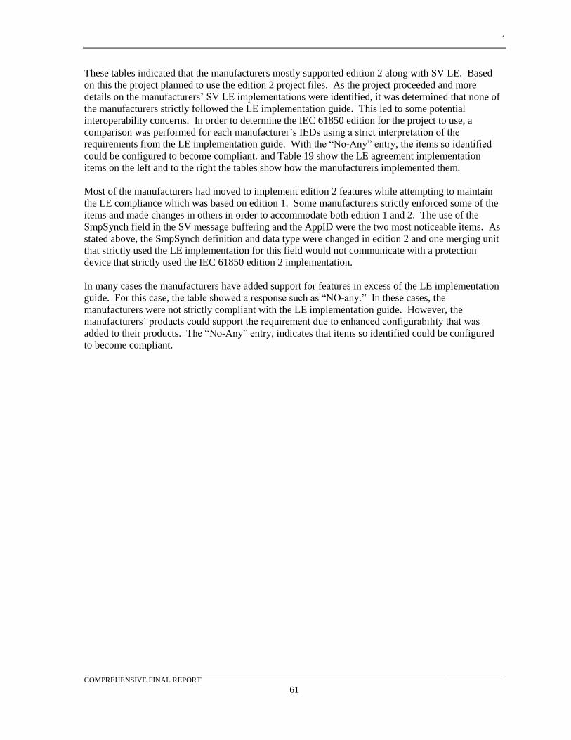
.
COMPREHENSIVE FINAL REPORT
61
These tables indicated that the manufacturers mostly supported edition 2 along with SV LE. Based
on this the project planned to use the edition 2 project files. As the project proceeded and more
details on the manufacturers’ SV LE implementations were identified, it was determined that none of
the manufacturers strictly followed the LE implementation guide. This led to some potential
interoperability concerns. In order to determine the IEC 61850 edition for the project to use, a
comparison was performed for each manufacturer’s IEDs using a strict interpretation of the
requirements from the LE implementation guide. With the “No-Any” entry, the items so identified
could be configured to become compliant. and Table 19 show the LE agreement implementation
items on the left and to the right the tables show how the manufacturers implemented them.
Most of the manufacturers had moved to implement edition 2 features while attempting to maintain
the LE compliance which was based on edition 1. Some manufacturers strictly enforced some of the
items and made changes in others in order to accommodate both edition 1 and 2. The use of the
SmpSynch field in the SV message buffering and the AppID were the two most noticeable items. As
stated above, the SmpSynch definition and data type were changed in edition 2 and one merging unit
that strictly used the LE implementation for this field would not communicate with a protection
device that strictly used the IEC 61850 edition 2 implementation.
In many cases the manufacturers have added support for features in excess of the LE implementation
guide. For this case, the table showed a response such as “NO-any.” In these cases, the
manufacturers were not strictly compliant with the LE implementation guide. However, the
manufacturers’ products could support the requirement due to enhanced configurability that was
added to their products. The “No-Any” entry, indicates that items so identified could be configured
to become compliant.
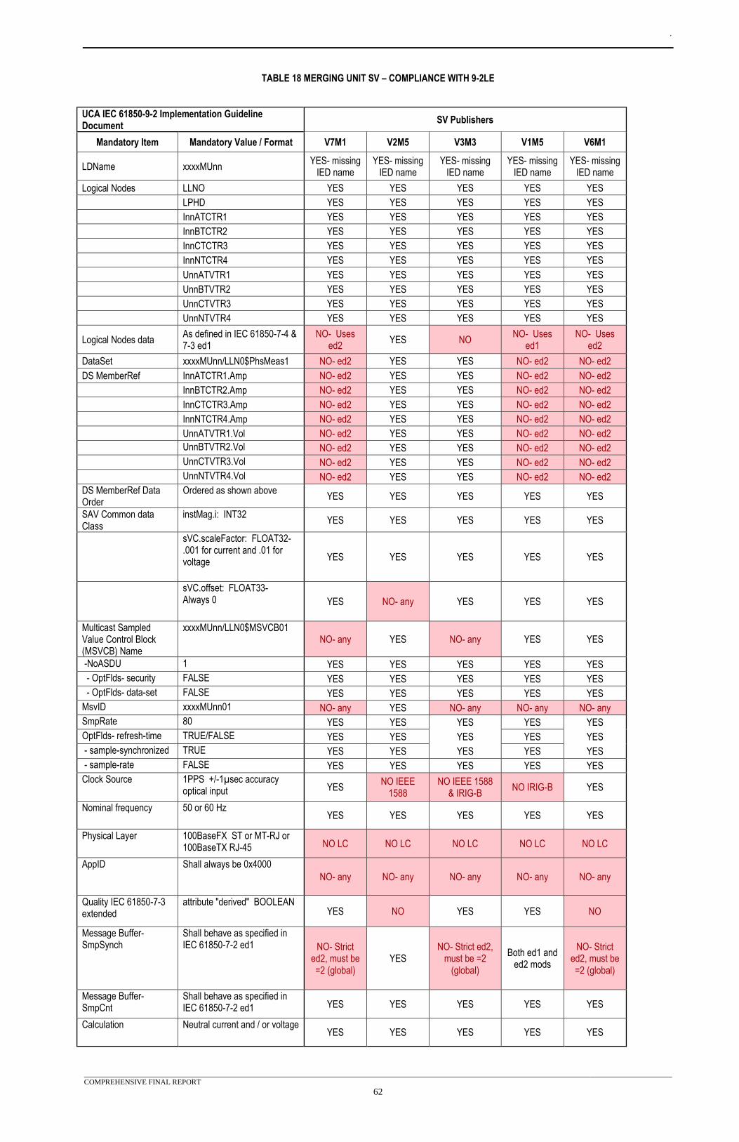
.
COMPREHENSIVE FINAL REPORT
62
TABLE 18 MERGING UNIT SV – COMPLIANCE WITH 9-2LE
UCA IEC 61850-9-2 Implementation Guideline Document
SV Publishers
Mandatory Item Mandatory Value / Format V7M1 V2M5 V3M3 V1M5 V6M1
LDName xxxxMUnn YES- missing
IED name YES- missing
IED name YES- missing
IED name YES- missing
IED name YES- missing
IED name
Logical Nodes LLNO YES YES YES YES YES
LPHD YES YES YES YES YES
InnATCTR1 YES YES YES YES YES
InnBTCTR2 YES YES YES YES YES
InnCTCTR3 YES YES YES YES YES
InnNTCTR4 YES YES YES YES YES
UnnATVTR1 YES YES YES YES YES
UnnBTVTR2 YES YES YES YES YES
UnnCTVTR3 YES YES YES YES YES
UnnNTVTR4 YES YES YES YES YES
Logical Nodes data As defined in IEC 61850-7-4 & 7-3 ed1
NO- Uses ed2
YES NO NO- Uses
ed1 NO- Uses
ed2
DataSet xxxxMUnn/LLN0$PhsMeas1 NO- ed2 YES YES NO- ed2 NO- ed2
DS MemberRef InnATCTR1.Amp NO- ed2 YES YES NO- ed2 NO- ed2
InnBTCTR2.Amp NO- ed2 YES YES NO- ed2 NO- ed2
InnCTCTR3.Amp NO- ed2 YES YES NO- ed2 NO- ed2
InnNTCTR4.Amp NO- ed2 YES YES NO- ed2 NO- ed2
UnnATVTR1.Vol NO- ed2 YES YES NO- ed2 NO- ed2
UnnBTVTR2.Vol NO- ed2 YES YES NO- ed2 NO- ed2
UnnCTVTR3.Vol NO- ed2 YES YES NO- ed2 NO- ed2
UnnNTVTR4.Vol NO- ed2 YES YES NO- ed2 NO- ed2
DS MemberRef Data Order
Ordered as shown above YES YES YES YES YES
SAV Common data Class
instMag.i: INT32 YES YES YES YES YES
sVC.scaleFactor: FLOAT32- .001 for current and .01 for voltage
YES YES YES YES YES
sVC.offset: FLOAT33- Always 0 YES NO- any YES YES YES
Multicast Sampled Value Control Block (MSVCB) Name
xxxxMUnn/LLN0$MSVCB01 NO- any YES NO- any YES YES
-NoASDU 1 YES YES YES YES YES
- OptFlds- security FALSE YES YES YES YES YES
- OptFlds- data-set FALSE YES YES YES YES YES
MsvID xxxxMUnn01 NO- any YES NO- any NO- any NO- any
SmpRate 80 YES YES YES YES YES
OptFlds- refresh-time TRUE/FALSE YES YES YES YES YES
- sample-synchronized TRUE YES YES YES YES YES
- sample-rate FALSE YES YES YES YES YES
Clock Source 1PPS +/-1µsec accuracy optical input YES
NO IEEE 1588
NO IEEE 1588 & IRIG-B
NO IRIG-B YES
Nominal frequency 50 or 60 Hz YES YES YES YES YES
Physical Layer 100BaseFX ST or MT-RJ or 100BaseTX RJ-45 NO LC NO LC NO LC NO LC NO LC
AppID Shall always be 0x4000
NO- any NO- any NO- any NO- any NO- any
Quality IEC 61850-7-3 extended
attribute "derived" BOOLEAN YES NO YES YES NO
Message Buffer- SmpSynch
Shall behave as specified in IEC 61850-7-2 ed1 NO- Strict
ed2, must be =2 (global)
YES NO- Strict ed2,
must be =2 (global)
Both ed1 and ed2 mods
NO- Strict ed2, must be =2 (global)
Message Buffer- SmpCnt
Shall behave as specified in IEC 61850-7-2 ed1 YES YES YES YES YES
Calculation Neutral current and / or voltage YES YES YES YES YES
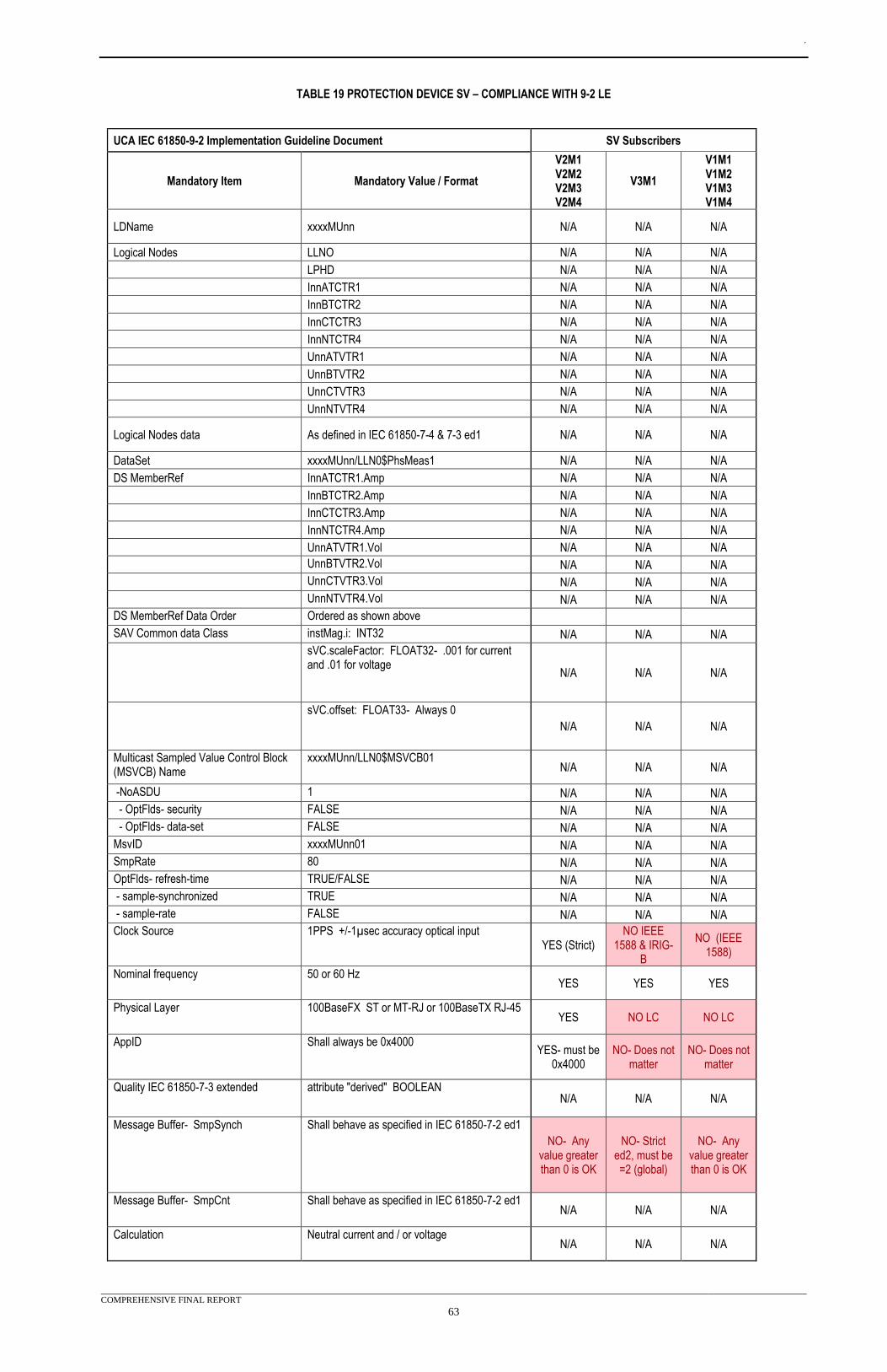
.
COMPREHENSIVE FINAL REPORT
63
TABLE 19 PROTECTION DEVICE SV – COMPLIANCE WITH 9-2 LE
UCA IEC 61850-9-2 Implementation Guideline Document SV Subscribers
Mandatory Item Mandatory Value / Format
V2M1 V2M2 V2M3 V2M4
V3M1
V1M1 V1M2 V1M3 V1M4
LDName xxxxMUnn N/A N/A N/A
Logical Nodes LLNO N/A N/A N/A
LPHD N/A N/A N/A
InnATCTR1 N/A N/A N/A
InnBTCTR2 N/A N/A N/A
InnCTCTR3 N/A N/A N/A
InnNTCTR4 N/A N/A N/A
UnnATVTR1 N/A N/A N/A
UnnBTVTR2 N/A N/A N/A
UnnCTVTR3 N/A N/A N/A
UnnNTVTR4 N/A N/A N/A
Logical Nodes data As defined in IEC 61850-7-4 & 7-3 ed1 N/A N/A N/A
DataSet xxxxMUnn/LLN0$PhsMeas1 N/A N/A N/A
DS MemberRef InnATCTR1.Amp N/A N/A N/A
InnBTCTR2.Amp N/A N/A N/A
InnCTCTR3.Amp N/A N/A N/A
InnNTCTR4.Amp N/A N/A N/A
UnnATVTR1.Vol N/A N/A N/A
UnnBTVTR2.Vol N/A N/A N/A
UnnCTVTR3.Vol N/A N/A N/A
UnnNTVTR4.Vol N/A N/A N/A
DS MemberRef Data Order Ordered as shown above
SAV Common data Class instMag.i: INT32 N/A N/A N/A
sVC.scaleFactor: FLOAT32- .001 for current and .01 for voltage
N/A N/A N/A
sVC.offset: FLOAT33- Always 0
N/A N/A N/A
Multicast Sampled Value Control Block (MSVCB) Name
xxxxMUnn/LLN0$MSVCB01 N/A N/A N/A
-NoASDU 1 N/A N/A N/A
- OptFlds- security FALSE N/A N/A N/A
- OptFlds- data-set FALSE N/A N/A N/A
MsvID xxxxMUnn01 N/A N/A N/A
SmpRate 80 N/A N/A N/A
OptFlds- refresh-time TRUE/FALSE N/A N/A N/A
- sample-synchronized TRUE N/A N/A N/A
- sample-rate FALSE N/A N/A N/A
Clock Source 1PPS +/-1µsec accuracy optical input YES (Strict)
NO IEEE 1588 & IRIG-
B
NO (IEEE 1588)
Nominal frequency 50 or 60 Hz YES YES YES
Physical Layer 100BaseFX ST or MT-RJ or 100BaseTX RJ-45 YES NO LC NO LC
AppID Shall always be 0x4000 YES- must be
0x4000 NO- Does not
matter NO- Does not
matter
Quality IEC 61850-7-3 extended attribute "derived" BOOLEAN N/A N/A N/A
Message Buffer- SmpSynch Shall behave as specified in IEC 61850-7-2 ed1
NO- Any value greater than 0 is OK
NO- Strict ed2, must be =2 (global)
NO- Any value greater than 0 is OK
Message Buffer- SmpCnt Shall behave as specified in IEC 61850-7-2 ed1 N/A N/A N/A
Calculation Neutral current and / or voltage N/A N/A N/A
.
COMPREHENSIVE FINAL REPORT
64
Data Flows
GOOSE and Sampled Value Data Flow Spreadsheet
The documents shown in Appendix E contain the data flow information for process bus #1, process
bus #2, and the station bus. Each SV and GOOSE message required a multicast MAC addresses,
AppIDs, and message IDs. This spreadsheet was created to identify the message requirements and to
establish the publishers and subscribers.
The following figures (Table 20, Table 21, Table 22, Table 23, Table 24, and Table 25) provide a sample
of the information contained in this appendix. The purpose of these figures was to orientate the
reader on their use and structure. The reader should reference the attached appendices for up to date
information on the data flows.
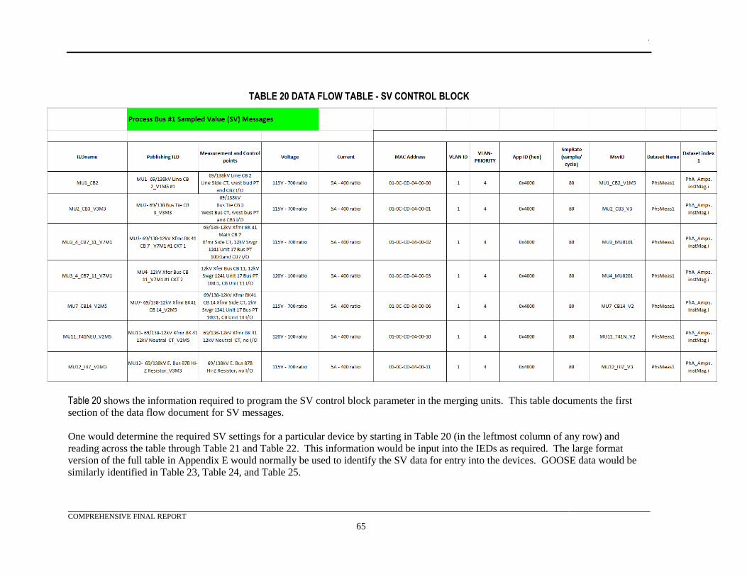
.
COMPREHENSIVE FINAL REPORT
65
TABLE 20 DATA FLOW TABLE - SV CONTROL BLOCK
Table 20 shows the information required to program the SV control block parameter in the merging units. This table documents the first
section of the data flow document for SV messages.
One would determine the required SV settings for a particular device by starting in Table 20 (in the leftmost column of any row) and
reading across the table through Table 21 and Table 22. This information would be input into the IEDs as required. The large format
version of the full table in Appendix E would normally be used to identify the SV data for entry into the devices. GOOSE data would be
similarly identified in Table 23, Table 24, and Table 25.
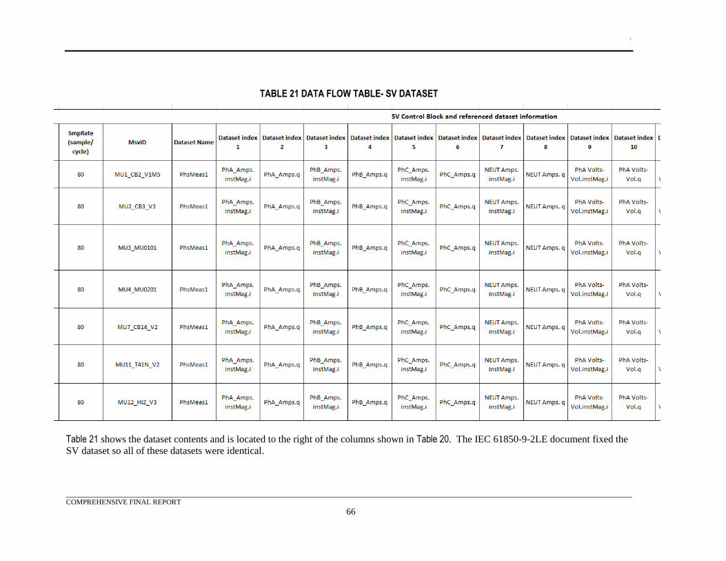
.
COMPREHENSIVE FINAL REPORT
66
TABLE 21 DATA FLOW TABLE- SV DATASET
Table 21 shows the dataset contents and is located to the right of the columns shown in Table 20. The IEC 61850-9-2LE document fixed the
SV dataset so all of these datasets were identical.
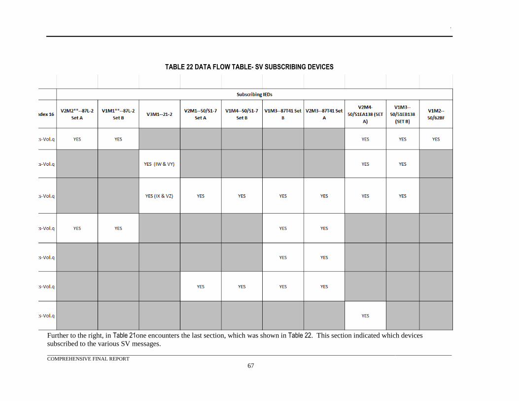
.
COMPREHENSIVE FINAL REPORT
67
TABLE 22 DATA FLOW TABLE- SV SUBSCRIBING DEVICES
Further to the right, in Table 21one encounters the last section, which was shown in Table 22. This section indicated which devices
subscribed to the various SV messages.
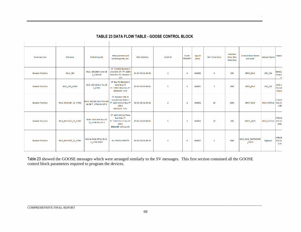
.
COMPREHENSIVE FINAL REPORT
68
TABLE 23 DATA FLOW TABLE - GOOSE CONTROL BLOCK
Table 23 showed the GOOSE messages which were arranged similarly to the SV messages. This first section contained all the GOOSE
control block parameters required to program the devices.
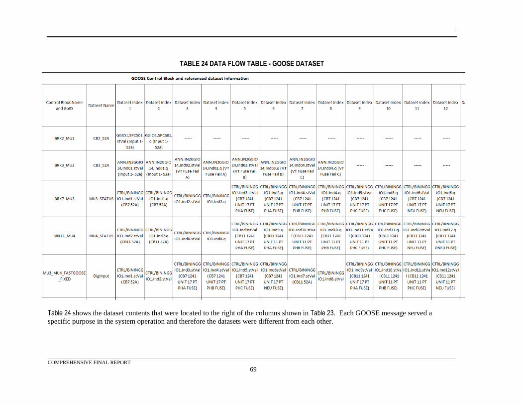
.
COMPREHENSIVE FINAL REPORT
69
TABLE 24 DATA FLOW TABLE - GOOSE DATASET
Table 24 shows the dataset contents that were located to the right of the columns shown in Table 23. Each GOOSE message served a
specific purpose in the system operation and therefore the datasets were different from each other.
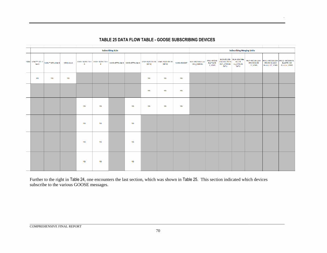
.
COMPREHENSIVE FINAL REPORT
70
TABLE 25 DATA FLOW TABLE - GOOSE SUBSCRIBING DEVICES
Further to the right in Table 24, one encounters the last section, which was shown in Table 25. This section indicated which devices
subscribe to the various GOOSE messages.
.
COMPREHENSIVE FINAL REPORT
71
Process Bus Data Flow Diagram
Figure 12 and Figure 13 show the data flow diagrams for process bus #1 and process bus #2,
respectively. The data flow diagrams provide a graphic representation of the data flow tables
presented in the previous section. The diagrams show all the GOOSE and SV data flows for each
process bus to and from each device connected to the process bus and the device’s relationship to the
substation equipment. The diagram was intended to provide an understanding of the purpose of the
data flow and provides information to link it to the data flow spreadsheet.
Additional information on the multicast MAC address was useful for quickly identifying the data
flow in a device configuration file or to analyze captured traffic on the network. SV message
addresses always start with 01-0C-CD-04 and GOOSE with 01-0C-CD-01 leaving the remaining two
octets available for configuration. For this project, the fifth octet was not used and set to 00, so, for
simplicity; the diagram only displays the value for the last octet. The octets used hex numbers but in
order to make the messages easier to identify, the MAC address were sequentially increased so as to
appear to be using base 10 numbers. As an example, the addresses jumped from 01-0C-CD-01-09 to
01-0C-CD-01-10 without using A, B, C, D, E or F in the last hex space.
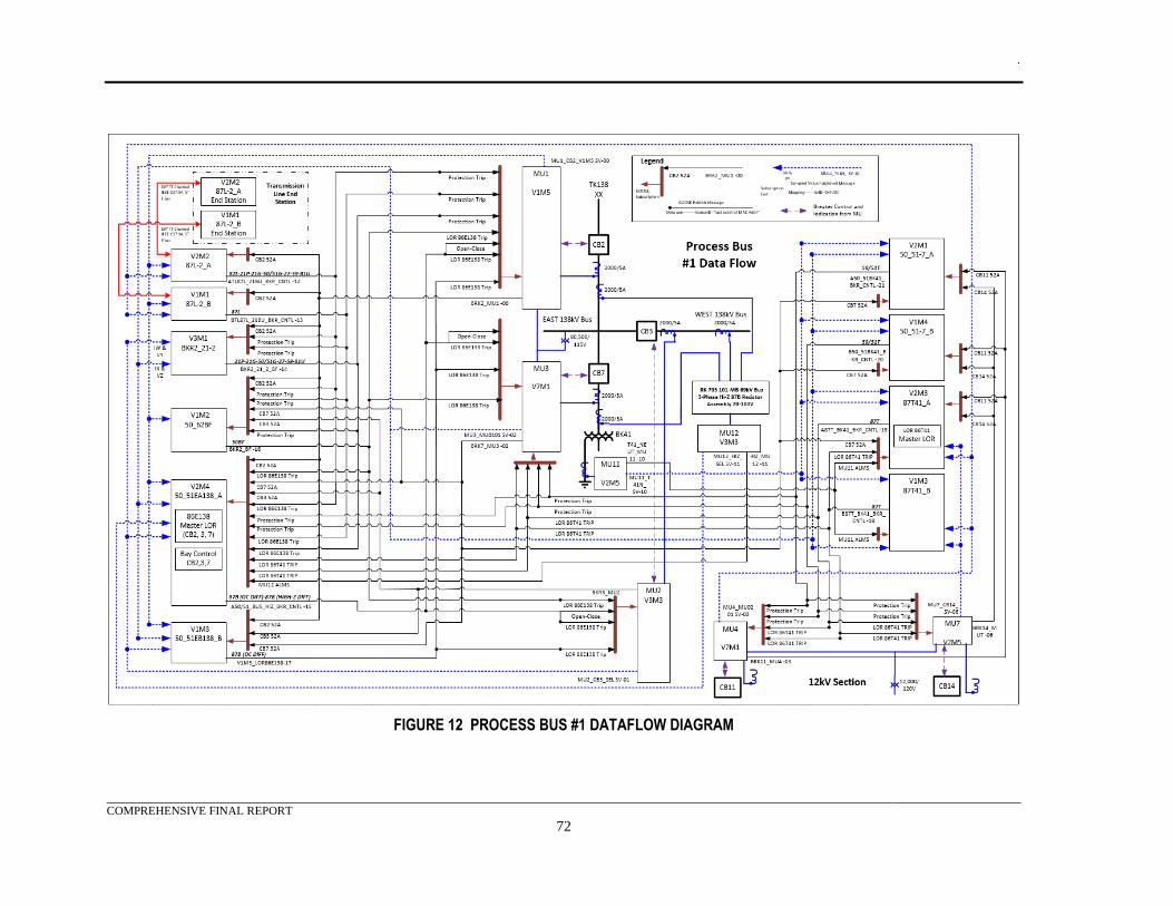
.
COMPREHENSIVE FINAL REPORT
72
FIGURE 12 PROCESS BUS #1 DATAFLOW DIAGRAM
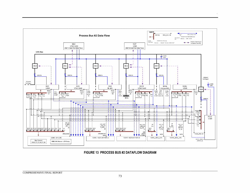
.
COMPREHENSIVE FINAL REPORT
73
FIGURE 13 PROCESS BUS #2 DATAFLOW DIAGRAM
.
COMPREHENSIVE FINAL REPORT
74
Station Bus Data Flow Diagram
Figure 14 shows the data flow diagram for the station bus. This data flow diagram provided a graphic
representation of the data flow tables presented in the previous section. The diagram showed all the
GOOSE data flows for the station bus to and from the devices and the device’s relationship to the
substation equipment. The diagram was intended to provide an understanding of the purpose of the
data flow and provided information to link it to the data flow spreadsheet.
The only function using the station bus was the reactor and capacitor bank control. This was the same
equipment and control philosophy as was currently used in the project team’s systems with the added
flexibility of GOOSE messaging. The V3M1 published the required analog measurement data to the
V3M4 controllers using GOOSE messaging. GOOSE messaging was also used to exchange
information for the bank protection equipment which included the V3M2 protection relays and the
V3M4 controllers.
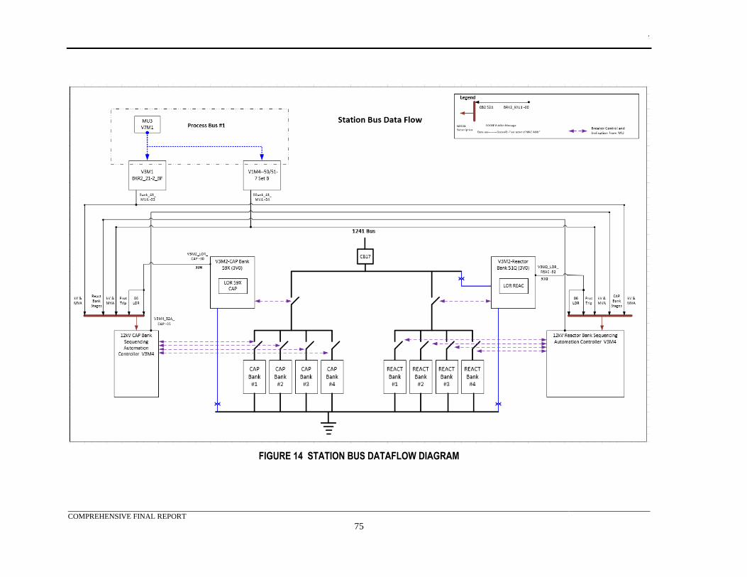
.
COMPREHENSIVE FINAL REPORT
75
FIGURE 14 STATION BUS DATAFLOW DIAGRAM
.
COMPREHENSIVE FINAL REPORT
76
Phase One Initial System Integration and Configuration
Throughout this project, a product code was assigned to each product. These codes were used to
obfuscate the manufacturer identity and model numbers of the products utilized in the test system.
This code was described in Appendix H.
This section covers the integration of the test system components. At this point in the process,
Vendor V1’s equipment had just arrived and was not included in the initial system check out. The
goal of the first phase of the testing was to determine if the equipment would support the critical
GOOSE and SV operations.
Vendor V2 Equipment
Vendor V2 sent two engineers to provide support during the three day testing exercise. In summary,
the vendor’s representatives were not able to get their protection relays to subscribe to any of the four
vendor merging units: Vendors V1, V3, V6, or V7. The following summarizes the integration and
results with the V2M1 relay:
• This protection relay successfully published and subscribed to the V2M6 I/O merging unit
MU8B_CB17_V2M6. The breaker simulator was successfully tripped and closed.
• This protection relay successfully published and subscribed to the V2M5 merging unit
MU5_CB10_V2M5. The breaker simulator was successfully tripped and closed.
• This manufacturer’s equipment attempted to subscribe to a SV stream using their
V2M1 protection relay from their V2M5 merging unit’s SV stream, but was not
successful. Many different configuration changes and system reconfigurations were
done in order to attempt to solve the problem. The following summarizes these
attempts:
o Validate that the V2M5 was synchronized to the PTP GPS Clock, which was
confirmed. Change the IRIG-B time input into the V2M1 protection relay from IEEE
1588 PTP to a direct 1PPS signal and validate it was time synchronized. This did not
make a difference.
o The vendor used their SV sniffing tool to determine that the V2M5 was publishing a
validate stream. No problems were detected.
o The vendor suggested that the AB and CD network connections could not be on the
same subnet IP address. Both were required to be connected to the process bus
because this vendor only supports SV from one port and GOOSE from the other.
This configuration was changed without resolution.
o The network sniffing tool was using to determine that the correct SV control block
parameters were being transmitted. The correct control block was being sent but the
time sync indication from the V2M5 indicated it was in local time, not using an
external source.
o This vendor made many configuration changes to include multicast MAC addresses,
AppIDs, datasets, etc. This did not make a difference.
o This vendor checked to verify that the license on the device supported the IEC 61850
functions. They found the licenses were correct.
.
COMPREHENSIVE FINAL REPORT
77
o This vendor requested a direct fiber point to point connection with their V2M5
merging unit to eliminate the existing process bus network. This was done with no
change noted.
• The V3M1 could not subscribe to the V2M5 merging unit either. The error on the V3M1 was
a time sync error. All other merging units presented a value of 2, meaning global time
traceable synchronization in the “smpSynch” field but the V2M5 had a value of 1, meaning
local time. A subscriber will not use the stream if it has lost global time but it was confirmed
that the V2M5 was synchronized to the PTP clock. The problem may be in IEC 61850
edition implementation. IEC 61850-9-2 Edition 1 specified the “smpSynch” as a Boolean
value with “0” meaning no time sync and “1” meaning good time sync. IEC 61850-9-2
Edition 2 specified the “smpSynch” as:
o 0= SV are not synchronized by an external clock signal.
o 1= SV are synchronized by a clock signal from an unspecified local area clock.
o 2= SV are synchronized by a global area clock signal (time traceable).
o 5 to 254= SV are synchronized by a clock signal from a local area clock identified by
this value.
o 3;4;255= Reserved values – Do not use.
• The IEC 61850-9-2LE document was based on edition 1 but most vendors have mixed
edition implementations focusing only on the dataset, sample rate, and naming conventions
from the LE document. The network sniffing tool SV decoder was using the edition 2
definitions of the “smpSynch” but it was postulated that the V2M5 may be using the edition 1
definition. This was thought to be why the V3M1 would not use the V2M5 SV stream, if it
used the edition 2 definition (that the time synchronization was bad when in reality it was
good).
o The vendor attempted to subscribe using their V2M1 protection relay to the other
vendor merging unit streams but each failed like the V2M5.
• The V6M1 CID file would import into the this vendor’s configuration software but when the
IEC 61850 component of the software was opened and then closed, it wrote over the MAC
address, AppIDs for both the GOOSE and SV control blocks. The software reset the values
to the first allowable values. This vendor agreed to investigate this behavior.
• This vendor’s merging units MU5 and MU11 were configured and tested for proper SV
publishing. Both had the local time sync indication in the stream.
This vendor had a system working at their corporate office, which they were using to compare
settings and system configuration to the project’s test system setup. It was based on this working
system that this vendor requested the various changes to the project’s test system in an attempt to get
their equipment to work with the V2M5 SV stream. None of the changes worked, nor did the
vendor’s equipment work on the other vendor’s merging units that were working in the system.
The plan was to ship the V2M5 and V2M1 IEDs back to the factory so that the vendor could work on
them at their factory. Their current working system was being used for another customer and could
not be shipped at the time. This vendor’s field engineers planned to return to implement their
findings.
.
COMPREHENSIVE FINAL REPORT
78
Vendor V3 Equipment
The team tested the V3M3 merging units and the V3M1 protection relay. The following summarizes
the results of the integration.
• The team configured the V3M3 MU12_HIZ_V3M3 merging unit and determined that it was
publishing the proper GOOSE and SV messages.
• This relay was able to successfully subscribe to the SV stream using the V3M1 relay’s WY
metering points. Preliminary checks using the test set software, V3M3 and V3M1 metering
functions showed that the streams were being transmitted and received correctly with no
errors.
• These devices controlled and received feedback using GOOSE to and from the V3M3
MU12_HIZ_V3M3 merging unit and V3M3 with a test bit. (The MU12_HIZ_V3M3 merging
unit did not have a connected breaker simulator in the test system).
• A second SV stream in the V3M3 using the XZ metering points from the V2M5 MU5
merging unit was configured. This first produced a configuration revision mismatch error
which was corrected and then produced a time sync error which was covered in the Vendor
V2 section.
• Configuration of the MU8A_CB17_V6M1 merging unit was attempted, but a CID file
schema error in the V3M6 software appeared when attempts to load the new CID file, into the
relay, were made. The V6M1 file loaded correctly in the V3M6 software and allowed the
data object to map into the V3M3 but the file would not load into the device. The
investigation was covered in the Vendor V6 section, and a successful download was
achieved.
• Configuration of the V7M1 MU9_10_CB11_14_V7M1 merging unit SV stream into the XZ
metering points was attempted but it was unsuccessful.
• The V3M3 MU12_HIZ_V3M3 merging unit stream was then removed from the WY
metering points and mapped only the V7M1 MU9_10_CB11_14_V7M1 merging unit SV
stream. This worked with no problems.
• The V7M1 MU9_10_CB11_14_V7M1 merging unit stream was then removed from the WY
metering points and mapped only the MU8A_CB17_V7M1 merging unit SV stream. This
change worked with no problems and avoided the V7M1 CID file problem with the V3M6
software by using the V3M7 software. The V3M7 SV setting overrode the V3M6 settings
and did not require the import of an IEC 61850 information exchange file.
• An attempt to add a second stream using the V3M3 MU12_HIZ_V3M3 merging unit to the
XZ metering points was made but this did not work.
• Vendor V3 merging units MU12, MU6 and MU2 were configured and tested for proper SV
and GOOSE publishing.
This problem was reported to the vendor.
Vendor V6 Equipment
There was only one V6M1 merging unit in the test system. The V6M1 did not have any control and
was only used as a SV merging unit. The following observations were from the integration of the
V6M1:
.
COMPREHENSIVE FINAL REPORT
79
• The V6M1 was configured and it was determined that the correct GOOSE and SV published
messages were being sent out onto the process bus.
• The V6M2 configuration software did not export an IEC 61850 ICD or CID file. The
manufacturer provided a XML template, which required manual input of the proper
information from the configuration files into a XML file. Problems arose with both the
V2M8 and V3M6 software when using this file. These problems prevented testing of the
GOOSE and SV message subscriptions. After a number of attempts to correct the file it was
determined that the template provided had too many problems to fix. The V7M1’s working
CID file was then modified to match the V6M1. This effort succeeded and the file was
successful with other third party device configuration tools.
• The V3M1 successfully subscribed to the 8A_CB17_V6M1 merging unit by using the V3M7
vs. the V3M6 software which removed the CID file problem.
• The V6M1 time source was changed to PTP from the IRIG-B connection. This change freed
up the fiber connected IRIG-B that provided time to the V3M2 capacitor and reactor bank
relays. The fiber converter was determined to be unable to drive all five units.
• After the time source change MU8A_CB_V6M1 was once again subscribed to the V3M3
relay to make sure there was still good time sync for the stream. Everything worked fine.
Vendor V7 Equipment
The V7M1 merging units were received just as the testing started but they were still installed and
prepared in time for this integration effort. The following were observations from the effort:
• The first unit that was powered-up would not publish any GOOSE or SV messages. It was
then configured as the MU3_4_CB7_11_V7M1 merging unit. The equipment successfully
took the configuration and all diagnostics and logs showed no errors but the unit was still not
publishing any messages. It was determined that the unit did have the latest firmware. The
manufacturer was contacted, they sent the same firmware, and suggested that the unit be re-
flashed. The manufacturer’s suggestions were deployed but the results were unchanged,
leaving the equipment in the same state.
• The second unit was then powered-up. This unit did publish GOOSE and SV streams. It was
then reconfigured to match the MU9_10_CB11_14_V7M1 settings in steps, checking after
each download that the unit was still publishing. Eventually the unit was fully configured
with the exception of the Ethernet ports IP addresses. These addresses were left at the default
values.
• It was determined that the SV stream was correct and the V3M1 protection relay was able to
subscribe to it.
• Given that the MU9_10_CB11_14_V7M1 unit worked using the default IP addresses the
configuration of the MU3_4_CB7_11_V7M1 merging unit was changed back to the default
IP addresses. The unit then successfully published GOOSE and SV messages.
• If the SVid name was put in as per the project documents, but the stream could not be read
without errors. Once the name was shorten by four characters, the streams worked properly
with the subscribers. All four V7M1 unit SVid names were changed.
• All four of Vendor V7 merging units MU3, MU4, MU9 and MU10 were configured and
tested successfully for proper SV publishing.
.
COMPREHENSIVE FINAL REPORT
80
Test Equipment
The team was able to configure the relay test sets to use the IRIG-B interface in order to run time
synchronized tests. The team was able to run a COMTRADE file play back through the relay test sets
and capture the secondary injection results. When compared, these results matched the expected
results and it was determined that the test system was working properly.
Network Equipment
The test system network equipment and configuration performance exceeded the requirements for this
test system. During the initial testing, up to nine SV streams ran over a single process bus along with
IEEE-1588 PTP, 10 active GOOSE messages, and configuration access. There were no performance
issues noted and no delay in configuration and monitoring access over the network.
Phase Two System Integration and Testing Results
This section covered the second phase integration and initial testing. The phase one testing identified
problems with V2M1, V2M2, V3M3, and V2M4 relays when subscribing to any merging unit
including the V2M5. It was also determined that the V2M5 SV stream could not be subscribed to by
the V3M1 even though it could subscribe to the remaining three models of merging units. In order to
perform this testing a number of devices were removed from their specified network interface. For
this testing these devices were returned back to their assigned networks.
There was also a problem with the V3M3 not subscribing to a second SV stream.
Vendor V3 Equipment
The following observations on this vendor’s equipment:
• Concerning the problem with the second V3M1 stream not working, all the files and
configurations were gathered and sent to the manufacturer. The manufacturer followed-up by
telephone and the situation was discussed. The manufacturer did not see any reason for the
lack of errors and the relay still indicated that it was subscribed to the stream. The following
was determined:
o The V3M1 was configured for both PTP and IRIG-B to allow for consideration of
redundancy options. It was assumed that the PTP would be the dominant source over
IRIG-B but what the V3M1 always defaults to the IRIG-B source. The manufacturer
suggested that the IRIG-B was disconnected and the relay was reconfigured to use
PTP. Upon completion, the second SV stream started working. The manufacturer
later informed the team that there was an additional IRIG-B setting to configure.
Under the global settings, time and date management, there was an IRIG-B setting.
When this was set to “none” the V3M1, for the purposes of the SV timing,
considered itself to be under “local” time even though it had an IRIG-B input.
Setting this to the “C37.118” setting changed its use of the IRIG-B signal to global
time (C37.118 is the standard for Synchro phasor Measurements for Power Systems).
The manufacturer used this to tie into the SV subscriptions for time synchronization.
Verification showed that the V3M1 time source switched to IRIG-B. The status of
the metering values for the first and second SV streams was then confirmed. Once
changed to “C37.118” and re-connected to the IRIG-B signal, both SV subscriptions
performed successfully with two streams using both PTP and IRIG-B.
o It was identified that V3M1 did not have error indication when a stream was dropped.
Only the “COM SV” command showed the status of the streams, but it required
manual checking.
.
COMPREHENSIVE FINAL REPORT
81
o This unit had a time differential field which was unused if locally synced but if global
sync was in place it indicated a time value. Global sync was required when using
more than one SV stream.
• The V3M1 sent both 3-phase voltage and MVA metering values to both V3M4s. It required
both the voltage from MU1 and the current from MU3 in order to calculate these metering
values. Since MU1 was not operating yet, to test this GOOSE interface MU3’s voltage was
temporarily directed to VY and it’s current to IX. MU3 would normally be mapped to VZ and
IX.
• Using the test set injection into MU3 and the metering calculation in the V3M1 it was
determined that the M3V4s were receiving the correct voltage and MVA values via GOOSE.
• Because of Vendor V2’s strict requirement to have the AppID set to 4000 for all SV
messages, V3M1 subscriptions were re-tested and no problems were identified.
Vendor V7 Equipment
The following changes were made to the V7M1 units:
• MU9_MU10 was temporarily placed on process bus #1 for testing. This relocation required a
change to the PTP domain to one from two. The PTP setting was then changed back to two
and the fiber connection moved to process bus #2. Checks were then performed to make sure
the PTP was synced up properly.
Vendor V6 Equipment
The following changes were made to the V6M1:
• V6M1 was temporarily placed on process bus #1 for testing, which required a change to the
PTP domain to one from two. The PTP setting was then changed back to two and the fiber
connection moved to process bus #2. Checks were then performed to make sure the PTP was
synced up properly.
Capacitor and Reactor Bank Control System
The capacitor and reactor bank control system were each consisted of a V3M2 protection relay and a
V3M4 automation controller. The concept was for the V3M2 to provide protection and the V3M4 to
provide the logic that controls the insertion and removal of the capacitor or reactor bank stages. The
V3M4 received the bus voltage and MVA metering data from both the V3M1-21-2 and V1M4-50/51-
7 Set B protection relays. During this phase of the testing Vendor V1 relays were not available but
V3M1 was running with two streams. The V3M3 units were fully configured and tested in the lab
using one of the data streams from the V3M1. The test used both the secondary injection test sets to
inject current and voltage into the merging units subscribed to by the V3M1. These values, through
logic calculations, were then passed to the V3M4 using GOOSE messaging.
The team found and corrected a number of problems with the logic, and in the end was able to
demonstrate that changes made at the test set correctly controlled the proper number of capacitor and
reactor banks.
Vendor V1 Equipment
The remaining Vendor V1 equipment arrived and the team worked on assembly and installation into
the racks. This work was in preparation for Vendor V1’s scheduled site visit.
.
COMPREHENSIVE FINAL REPORT
82
• The installation for the V1M5s was completed. While working on the Vendor V2 solution it
was identified that V1M5 was also streaming on process bus #1. Its AppID was 4000 and
MAC address was 00 which was the proper configuration for MU1. A fifth stream was added
to the V2M3 87T41 but it would not subscribe to the stream. Using the manufacturer’s SV
browser it was determined that the stream was set for 50 hertz which caused the stream to be
dropped.
• The SymSync field indicated a value of 1 “local” with an IRIG-B signal on the time signal
fiber input. The unit would not accept a 1PPS signal without the unit configuration tools on-
site. This would be accomplished with Vendor V1’s engineers.
Vendor V2 Equipment
This manufacturer found a working solution and returned the shipped equipment back to the lab. The
manufacturer also sent an engineering team to report on the problems found from their team’s
investigation and what needed to be changed in order to get their equipment running in the test
system. The following summarizes the meeting and re-test results:
• The manufacturer found two problems, the first was that the V2M1, V2M2, V2M3, and
V2M4 protection relays strictly adhered to the LE document stating that only an AppID of
4000 could be used. The device rejected any SV stream that did not have an AppID of 4000.
This was the only setting that was not changed during the manufacturer’s first three day on-
site testing.
• The V2M1, V2M2, V2M3, and V2M4 relays will accept both IRIG-B (hardwired input) and
1PPS (fiber input). The device however, required 1PPS when SV stream synchronization
was required per the LE document. This was attempted during the manufacturer’s first visit
but since the AppID was not set to 4000, the SV subscriptions did not work.
• Once the AppID for the V2M5 MU11 merging units and both of the V7M1 MU3 and MU4
were changed to 4000, SV subscriptions were successful. To confirm a different relay,
V2M3 87T41 Set A, was used to perform the tests. This relay successfully subscribed to all
three streams with no errors. Injection of currents and voltages into all three merging units
and showed that the metering functions on the V2M3 87T41 Set A were accurately indicating
the correct metering values.
Phase three system integration and testing results
The primary purpose for this testing session was to work with the Vendor V1 engineer to get the
Vendor V1 equipment and software working within the test system. The following summarized the
findings:
• MU1 V1M5 was configured per the data flow diagram. The following items were identified:
o The V1M5 did not support 1PPS on the time source fiber input, only IRIG-B. It did
not support IEEE 1588 either, so the IRIG-B fiber signal was used.
o No configuration parameter was available to tell the MU to calculate the In and Vn
values when there was no connection available. The LE document states this and
adds a “derived” bit to the quality for the value. This parameter existed on all the
other merging units and they all reported “derived” on the In and Vn. The V1M5 did
not.
o With the unit’s web page interface, it was seen that the unit was successfully time
syncing to the IRIG-B signal.
.
COMPREHENSIVE FINAL REPORT
83
o These next two points indicate that the unit had fully switched from publishing an SV
LE message to an edition 2 SV message.
▪ The network sniffer could not parse out the SV message using the LE
decoder. It was suspected that when the unit was configured for edition 2, it
used an edition 2 message buffer not an edition 1 based LE message buffer.
This put additional fields in the message that the network sniffer could not
decode.
▪ The “SymSync” field was no longer BOOLEAN as the fault published
message indicated. It published an edition 2 value of “2” global.
o Attempts to subscribe to the MU1 stream from the V3M1 relay were unsuccessful.
The PDU length error indicated by the V3M1 was the same error type shown in the
network traffic capture, which indicated that the SV message had the addition edition
2 fields. The additional edition 2 fields could not be processed by the V3M1 relay.
• The V2M2 87L set A relay was then subscribed to the MU1 stream and had no problems. The
SV stream values and synchronization were successful.
The V1M5 merging unit, unlike all the others, completely changed its mode of operation when the
unit was configured as edition 1 or edition 2. For full SV LE compatibility one must configure the
unit as edition 1. As configured in edition 2 the MU published edition 2 message buffer with the
additional fields that were non-LE. It also changed how it published the SymSync field from the
BOOLEAN edition 1 definition to the INT edition 2 definitions. The current overwhelming system
support was for edition 2 having vendors offer edition 2 GOOSE and files while still using SV LE
based on edition 1. Having the V1M5 being one or the other presented a problem when integrating it
into the system. The following captures some of the high level problems:
• If one left the V1M5 at edition 2:
o The V3M1 would not subscribe to the V1M5 SV stream. This was due to the way
that V3M1 examined the SV message and finding an additional field that it cannot
understand. The V3M1 dropped the stream at this point.
o The V2M1, V2M2, V2M3, and V2M4 relays would subscribe to the V1M5 SV
stream. They reacted differently by not analyzing the entire message and accepting it
even though it had an additional field.
o The Vendor V1 relays would subscribe to the V1M5.
o All IEC 61850 files were in edition 2 format and transferred between the various
vendor tools. Both V2M8 and V1M9 tools only accepted the edition files for eth
project edition in use at the time, which was edition 2.
• If one changed the V1M5 MU back to edition 1:
o The IEC 61850 file format for the V1M5 MU would need to be modified to look like
an edition 2 file in order to use it in both the V2M8 and V1M9 configuration tools.
o The V3M1 would still not be able to subscribe to the SV stream. By changing the
MU configuration to edition 1 the SymSync field would change to BOOLEAN which
would publish a true “1” value for good time synchronization per the edition 1 and
LE documents. The V3M1 only interpreted this field as edition 2, which meant that
the V3M1 thought that the MU was only locally time synchronized with no global
synchronization. With this indication it would not synchronize with multiple SV
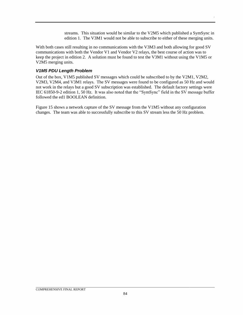
.
COMPREHENSIVE FINAL REPORT
84
streams. This situation would be similar to the V2M5 which published a SymSync in
edition 1. The V3M1 would not be able to subscribe to either of these merging units.
With both cases still resulting in no communications with the V3M3 and both allowing for good SV
communications with both the Vendor V1 and Vendor V2 relays, the best course of action was to
keep the project in edition 2. A solution must be found to test the V3M1 without using the V1M5 or
V2M5 merging units.
V1M5 PDU Length Problem
Out of the box, V1M5 published SV messages which could be subscribed to by the V2M1, V2M2,
V2M3, V2M4, and V3M1 relays. The SV messages were found to be configured as 50 Hz and would
not work in the relays but a good SV subscription was established. The default factory settings were
IEC 61850-9-2 edition 1, 50 Hz. It was also noted that the “SymSync” field in the SV message buffer
followed the ed1 BOOLEAN definition.
Figure 15 shows a network capture of the SV message from the V1M5 without any configuration
changes. The team was able to successfully subscribe to this SV stream less the 50 Hz problem.
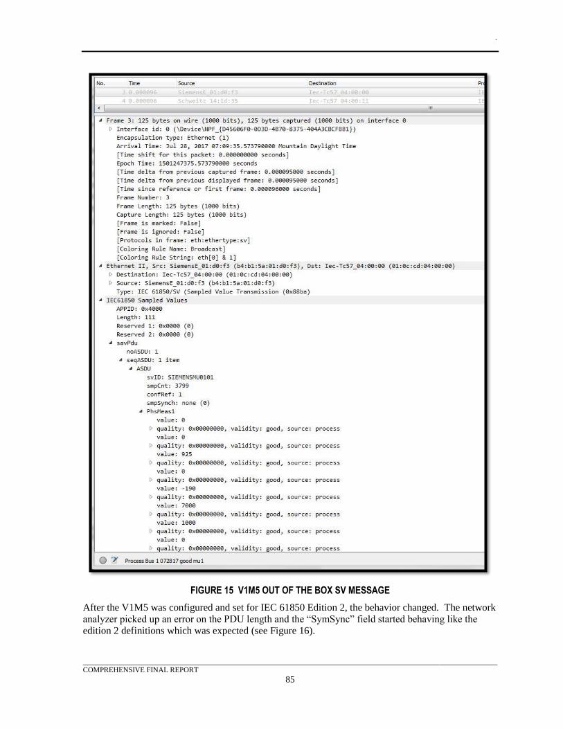
.
COMPREHENSIVE FINAL REPORT
85
FIGURE 15 V1M5 OUT OF THE BOX SV MESSAGE
After the V1M5 was configured and set for IEC 61850 Edition 2, the behavior changed. The network
analyzer picked up an error on the PDU length and the “SymSync” field started behaving like the
edition 2 definitions which was expected (see Figure 16).
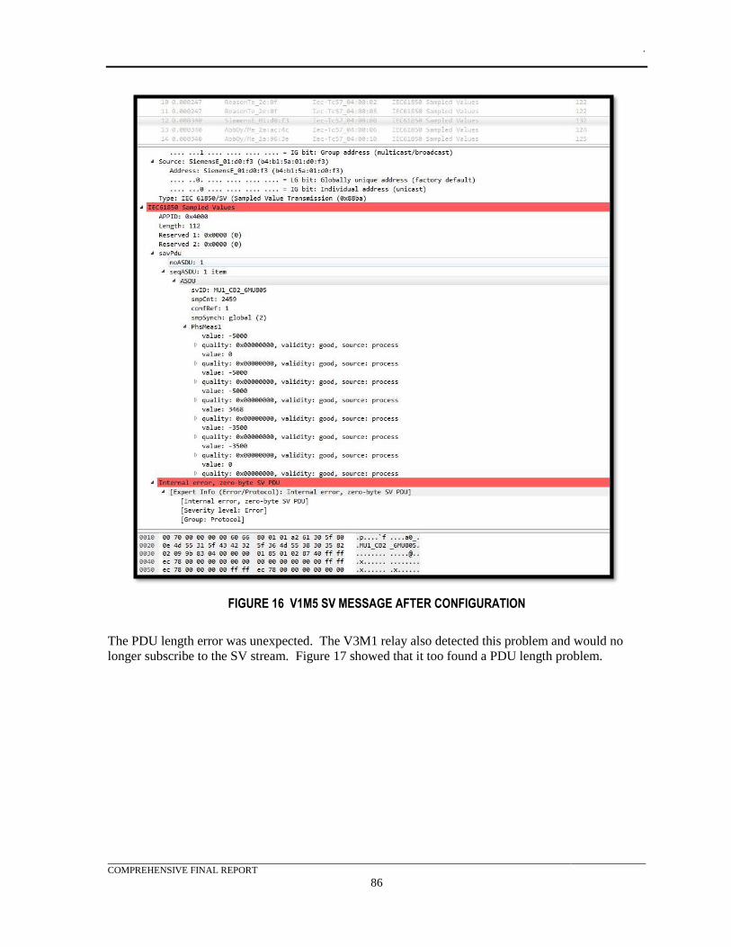
.
COMPREHENSIVE FINAL REPORT
86
FIGURE 16 V1M5 SV MESSAGE AFTER CONFIGURATION
The PDU length error was unexpected. The V3M1 relay also detected this problem and would no
longer subscribe to the SV stream. Figure 17 showed that it too found a PDU length problem.
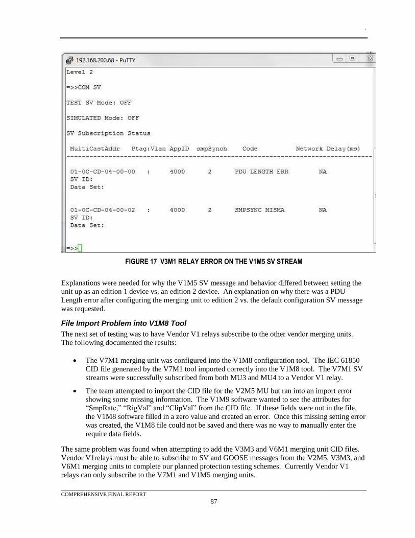
.
COMPREHENSIVE FINAL REPORT
87
FIGURE 17 V3M1 RELAY ERROR ON THE V1M5 SV STREAM
Explanations were needed for why the V1M5 SV message and behavior differed between setting the
unit up as an edition 1 device vs. an edition 2 device. An explanation on why there was a PDU
Length error after configuring the merging unit to edition 2 vs. the default configuration SV message
was requested.
File Import Problem into V1M8 Tool
The next set of testing was to have Vendor V1 relays subscribe to the other vendor merging units.
The following documented the results:
• The V7M1 merging unit was configured into the V1M8 configuration tool. The IEC 61850
CID file generated by the V7M1 tool imported correctly into the V1M8 tool. The V7M1 SV
streams were successfully subscribed from both MU3 and MU4 to a Vendor V1 relay.
• The team attempted to import the CID file for the V2M5 MU but ran into an import error
showing some missing information. The V1M9 software wanted to see the attributes for
“SmpRate,” “RigVal” and “ClipVal” from the CID file. If these fields were not in the file,
the V1M8 software filled in a zero value and created an error. Once this missing setting error
was created, the V1M8 file could not be saved and there was no way to manually enter the
require data fields.
The same problem was found when attempting to add the V3M3 and V6M1 merging unit CID files.
Vendor V1relays must be able to subscribe to SV and GOOSE messages from the V2M5, V3M3, and
V6M1 merging units to complete our planned protection testing schemes. Currently Vendor V1
relays can only subscribe to the V7M1 and V1M5 merging units.
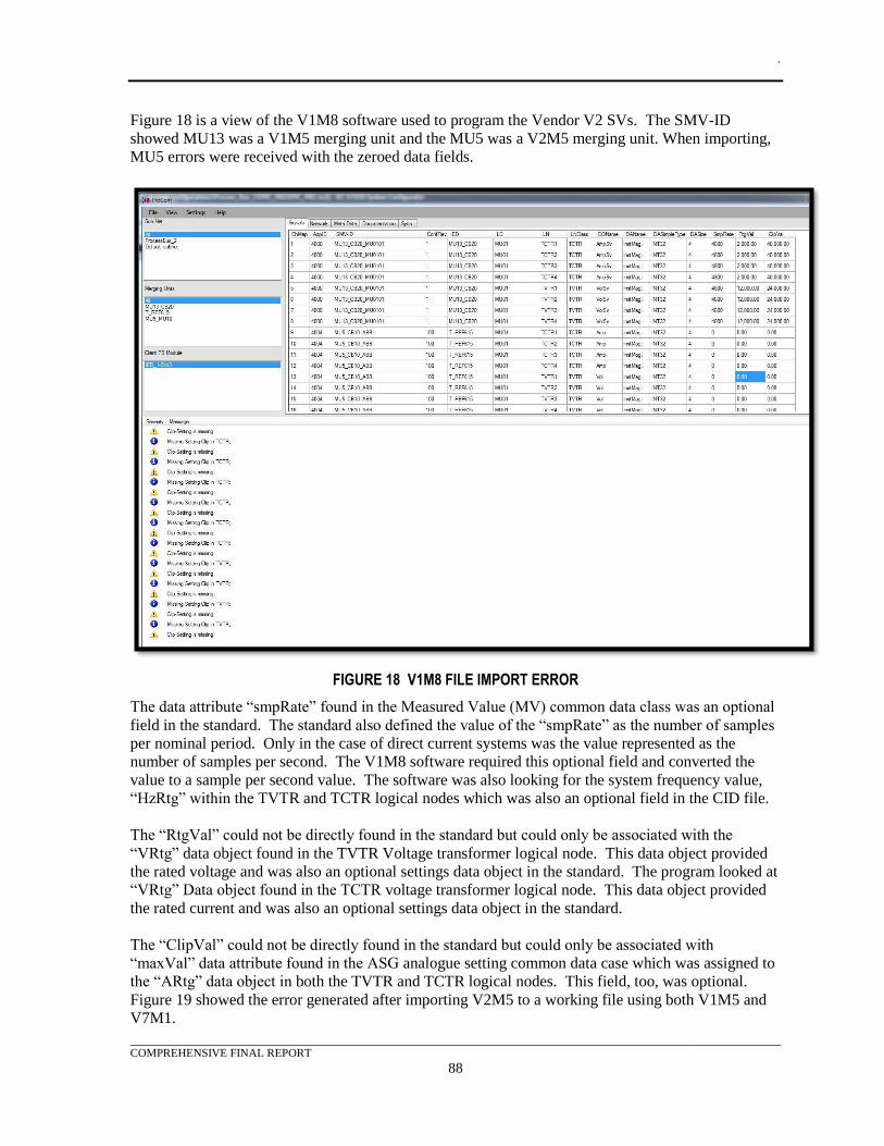
.
COMPREHENSIVE FINAL REPORT
88
Figure 18 is a view of the V1M8 software used to program the Vendor V2 SVs. The SMV-ID
showed MU13 was a V1M5 merging unit and the MU5 was a V2M5 merging unit. When importing,
MU5 errors were received with the zeroed data fields.
FIGURE 18 V1M8 FILE IMPORT ERROR
The data attribute “smpRate” found in the Measured Value (MV) common data class was an optional
field in the standard. The standard also defined the value of the “smpRate” as the number of samples
per nominal period. Only in the case of direct current systems was the value represented as the
number of samples per second. The V1M8 software required this optional field and converted the
value to a sample per second value. The software was also looking for the system frequency value,
“HzRtg” within the TVTR and TCTR logical nodes which was also an optional field in the CID file.
The “RtgVal” could not be directly found in the standard but could only be associated with the
“VRtg” data object found in the TVTR Voltage transformer logical node. This data object provided
the rated voltage and was also an optional settings data object in the standard. The program looked at
“VRtg” Data object found in the TCTR voltage transformer logical node. This data object provided
the rated current and was also an optional settings data object in the standard.
The “ClipVal” could not be directly found in the standard but could only be associated with
“maxVal” data attribute found in the ASG analogue setting common data case which was assigned to
the “ARtg” data object in both the TVTR and TCTR logical nodes. This field, too, was optional.
Figure 19 showed the error generated after importing V2M5 to a working file using both V1M5 and
V7M1.
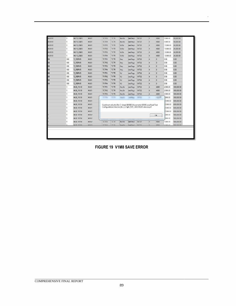
.
COMPREHENSIVE FINAL REPORT
89
FIGURE 19 V1M8 SAVE ERROR
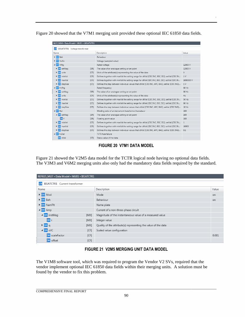
.
COMPREHENSIVE FINAL REPORT
90
Figure 20 showed that the V7M1 merging unit provided these optional IEC 61850 data fields.
FIGURE 20 V7M1 DATA MODEL
Figure 21 showed the V2M5 data model for the TCTR logical node having no optional data fields.
The V3M3 and V6M2 merging units also only had the mandatory data fields required by the standard.
FIGURE 21 V2M5 MERGING UNIT DATA MODEL
The V1M8 software tool, which was required to program the Vendor V2 SVs, required that the
vendor implement optional IEC 61850 data fields within their merging units. A solution must be
found by the vendor to fix this problem.
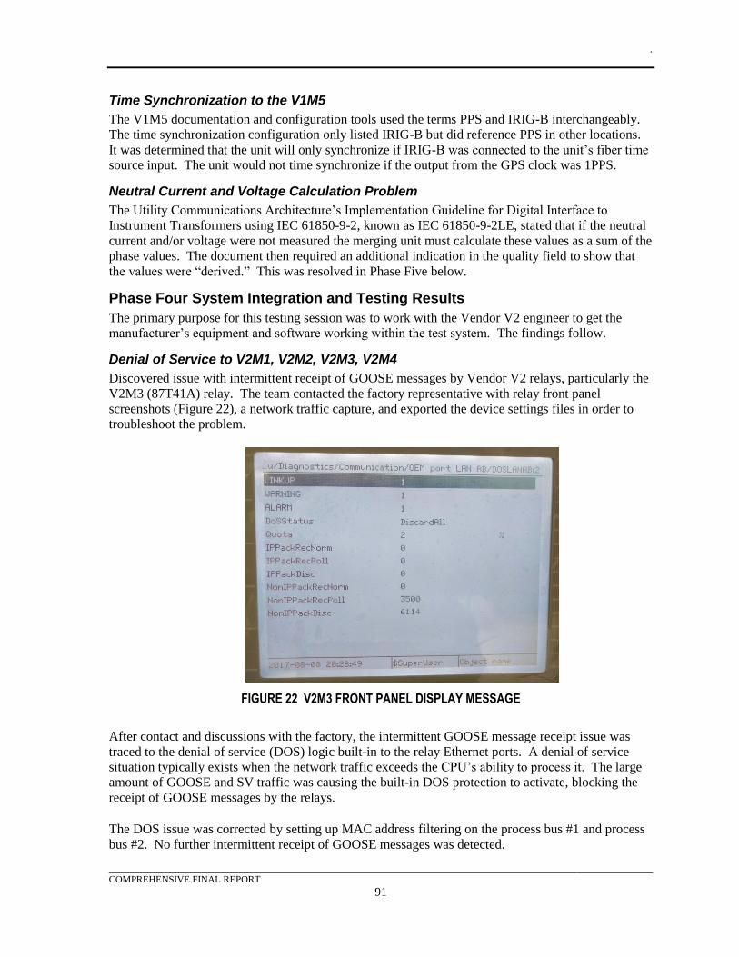
.
COMPREHENSIVE FINAL REPORT
91
Time Synchronization to the V1M5
The V1M5 documentation and configuration tools used the terms PPS and IRIG-B interchangeably.
The time synchronization configuration only listed IRIG-B but did reference PPS in other locations.
It was determined that the unit will only synchronize if IRIG-B was connected to the unit’s fiber time
source input. The unit would not time synchronize if the output from the GPS clock was 1PPS.
Neutral Current and Voltage Calculation Problem
The Utility Communications Architecture’s Implementation Guideline for Digital Interface to
Instrument Transformers using IEC 61850-9-2, known as IEC 61850-9-2LE, stated that if the neutral
current and/or voltage were not measured the merging unit must calculate these values as a sum of the
phase values. The document then required an additional indication in the quality field to show that
the values were “derived.” This was resolved in Phase Five below.
Phase Four System Integration and Testing Results
The primary purpose for this testing session was to work with the Vendor V2 engineer to get the
manufacturer’s equipment and software working within the test system. The findings follow.
Denial of Service to V2M1, V2M2, V2M3, V2M4
Discovered issue with intermittent receipt of GOOSE messages by Vendor V2 relays, particularly the
V2M3 (87T41A) relay. The team contacted the factory representative with relay front panel
screenshots (Figure 22), a network traffic capture, and exported the device settings files in order to
troubleshoot the problem.
FIGURE 22 V2M3 FRONT PANEL DISPLAY MESSAGE
After contact and discussions with the factory, the intermittent GOOSE message receipt issue was
traced to the denial of service (DOS) logic built-in to the relay Ethernet ports. A denial of service
situation typically exists when the network traffic exceeds the CPU’s ability to process it. The large
amount of GOOSE and SV traffic was causing the built-in DOS protection to activate, blocking the
receipt of GOOSE messages by the relays.
The DOS issue was corrected by setting up MAC address filtering on the process bus #1 and process
bus #2. No further intermittent receipt of GOOSE messages was detected.
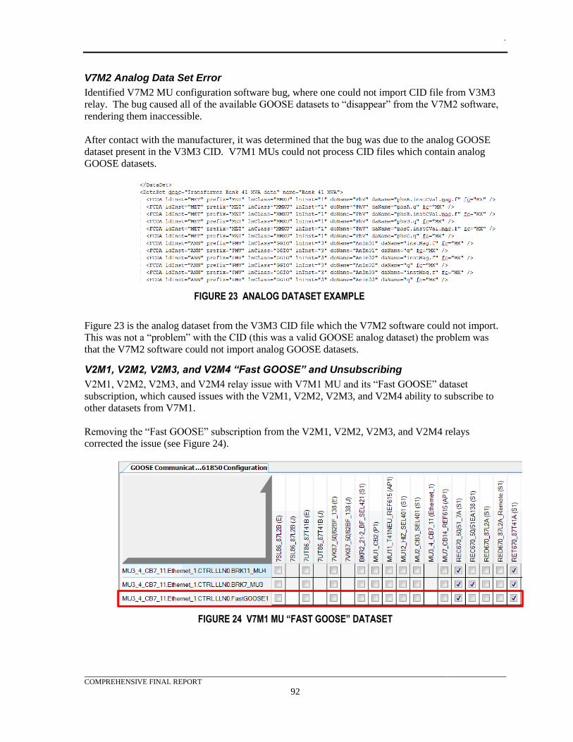
.
COMPREHENSIVE FINAL REPORT
92
V7M2 Analog Data Set Error
Identified V7M2 MU configuration software bug, where one could not import CID file from V3M3
relay. The bug caused all of the available GOOSE datasets to “disappear” from the V7M2 software,
rendering them inaccessible.
After contact with the manufacturer, it was determined that the bug was due to the analog GOOSE
dataset present in the V3M3 CID. V7M1 MUs could not process CID files which contain analog
GOOSE datasets.
FIGURE 23 ANALOG DATASET EXAMPLE
Figure 23 is the analog dataset from the V3M3 CID file which the V7M2 software could not import.
This was not a “problem” with the CID (this was a valid GOOSE analog dataset) the problem was
that the V7M2 software could not import analog GOOSE datasets.
V2M1, V2M2, V2M3, and V2M4 “Fast GOOSE” and Unsubscribing
V2M1, V2M2, V2M3, and V2M4 relay issue with V7M1 MU and its “Fast GOOSE” dataset
subscription, which caused issues with the V2M1, V2M2, V2M3, and V2M4 ability to subscribe to
other datasets from V7M1.
Removing the “Fast GOOSE” subscription from the V2M1, V2M2, V2M3, and V2M4 relays
corrected the issue (see Figure 24).
FIGURE 24 V7M1 MU “FAST GOOSE” DATASET
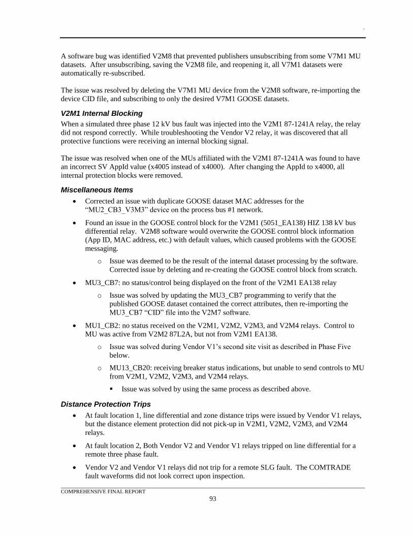
.
COMPREHENSIVE FINAL REPORT
93
A software bug was identified V2M8 that prevented publishers unsubscribing from some V7M1 MU
datasets. After unsubscribing, saving the V2M8 file, and reopening it, all V7M1 datasets were
automatically re-subscribed.
The issue was resolved by deleting the V7M1 MU device from the V2M8 software, re-importing the
device CID file, and subscribing to only the desired V7M1 GOOSE datasets.
V2M1 Internal Blocking
When a simulated three phase 12 kV bus fault was injected into the V2M1 87-1241A relay, the relay
did not respond correctly. While troubleshooting the Vendor V2 relay, it was discovered that all
protective functions were receiving an internal blocking signal.
The issue was resolved when one of the MUs affiliated with the V2M1 87-1241A was found to have
an incorrect SV AppId value (x4005 instead of x4000). After changing the AppId to x4000, all
internal protection blocks were removed.
Miscellaneous Items
• Corrected an issue with duplicate GOOSE dataset MAC addresses for the
“MU2_CB3_V3M3” device on the process bus #1 network.
• Found an issue in the GOOSE control block for the V2M1 (5051_EA138) HIZ 138 kV bus
differential relay. V2M8 software would overwrite the GOOSE control block information
(App ID, MAC address, etc.) with default values, which caused problems with the GOOSE
messaging.
o Issue was deemed to be the result of the internal dataset processing by the software.
Corrected issue by deleting and re-creating the GOOSE control block from scratch.
• MU3_CB7: no status/control being displayed on the front of the V2M1 EA138 relay
o Issue was solved by updating the MU3_CB7 programming to verify that the
published GOOSE dataset contained the correct attributes, then re-importing the
MU3_CB7 “CID” file into the V2M7 software.
• MU1_CB2: no status received on the V2M1, V2M2, V2M3, and V2M4 relays. Control to
MU was active from V2M2 87L2A, but not from V2M1 EA138.
o Issue was solved during Vendor V1’s second site visit as described in Phase Five
below.
o MU13_CB20: receiving breaker status indications, but unable to send controls to MU
from V2M1, V2M2, V2M3, and V2M4 relays.
▪ Issue was solved by using the same process as described above.
Distance Protection Trips
• At fault location 1, line differential and zone distance trips were issued by Vendor V1 relays,
but the distance element protection did not pick-up in V2M1, V2M2, V2M3, and V2M4
relays.
• At fault location 2, Both Vendor V2 and Vendor V1 relays tripped on line differential for a
remote three phase fault.
• Vendor V2 and Vendor V1 relays did not trip for a remote SLG fault. The COMTRADE
fault waveforms did not look correct upon inspection.
.
COMPREHENSIVE FINAL REPORT
94
• Both Vendor V2 and Vendor V1 relays tripped on line differential for remote line-line fault.
• V2M2 87L protection for fault locations 1 through 3. Noted that V2M2 distance protection
would pick-up for close-in faults, but not remote faults.
o Distance elements were having issues detecting both phase and ground faults using
the simulated COMTRADE files.
o Issue partially resolved by increasing the local source strength in the RTDS model.
o Issue with phase distance elements was resolved by adjusting the pickups to values of
secondary ohms (the manufacturer had previously indicated that the values should be
in primary ohms).
o Issue with ground distance elements was resolved by disconnecting the neutral
current “IN” portion SV DataStream, received from the MU1_CB2_V1M5, from the
internal programming in the V2M1, V2M2, V2M3, and V2M4 relays. The V1M5
MU was not transmitting a neutral/residual current value to the V2M1, V2M2,
V2M3, and V2M4 relays, hence the neutral/residual current channel was being
continuously written to a value of “0.” Disconnecting the neutral current “IN” data
stream, in the project file and reapplying it to the relays, allowed the V2M1, V2M2,
V2M3, and V2M4 relays to internally calculate residual ground currents from the
measured phase currents, resulting in correct distance element operation.
• V1M5 MUs were still unable to receive single point controls issued by the various Vendor
V2 relays. Contacted both manufacturers, but still waiting on feedback. V1M5 MUs appear
to only be controllable by the “SMPPTRC” tripping block (present in the V2M1 87L2A
relay, which was the only device configured to control the V1M5 MU).
Phase Five System Integration and Testing Results
The primary purpose for this testing session was to work with the Vendor V1 engineer to resolve the
outstanding configuration issues and get this manufacturer’s equipment and software working within
the test system. The following summarized the findings:
• Single-point TRIP/CLOSE commands sent to V1M5 MUs from the V2M1, V2M2, V3M3,
and V2M4 relays were non-functional. Vendor V1 began by troubleshooting the issue with
V1M5 MUs not receiving single-point commands correctly. The factory representative spent
several hours troubleshooting the V1M5 MUs using a network traffic analyzer and the MUs
online diagnostic tools. No errors were found in the relay or MU configurations, the V1M5
MUs simply could not interpret the published datasets
o Final resolution: issue was related to problems in the headers of the “.ICD” files
exported from the V2M8 software. Corrected the issue by manually modifying the
“.CID” files exported from the V2M8 software into “.ICD” files, which were
imported into the V1M9 software. Previously, “.ICD” files created directly from the
V2M8 software had been used to attempt to set up the GOOSE subscriptions.
• The 138 kV breaker failure protection (V1M2 relay) was non-functional.
Troubleshooting the 138 kV breaker failure protection (V1M2) involved verification that the
breaker failure initiated and the breaker status were being received correctly via GOOSE. No
issues were found in the existing programming.
o Final resolution: The factory representative adjusted some of the breaker failure set
points and the breaker failure protection was tested and found to work correctly.
.
COMPREHENSIVE FINAL REPORT
95
Developed Algorithms
Two algorithms were developed during the test design phase. They were the reactive bank automation
and the bus lockout function. These algorithms did not previously exist and were developed
specifically for this project. These functions were essential to certain protection schemes and while
legacy devices may have these functions included, they were easily configured in the test devices due
to the versatile nature of IEC 61850 GOOSE messaging.
Capacitor and Reactor Bank
Capacitor and reactor bank VAR control automation was a specific use case that demonstrated the
power of GOOSE analog and digital messaging and can eliminate the point-to-point digital signaling
currently used in existing distribution substation applications.
This use case included two VAR automation controllers, a transformer overcurrent relay (50/51T),
and two reactive bank imbalance protection relays. It was important to note that the automation
controllers’ options were anticipated to be the same as the current standard part number with the
addition of the IEC 61850 GOOSE option. This similarity allowed the majority of the existing logic
settings to be reused.
The 50/51T relay provided both of the automation controllers with analog GOOSE messages
representing the transformer VAR demand measured at the high side of the terminal. This facilitated
addition and subtraction of capacitor/reactor elements to minimize transformer VAR demand, and in
turn regulate bus voltage. This scheme was designed to allow up to two 50/51T relays to transmit the
GOOSE analog VAR values to the automation controllers. Automatic throw-over logic was included
to switch between the sources to prevent relay failure or maintenance from disturbing the automatic
reactance control scheme.
One automation controller was dedicated to controlling the capacitor bank stages, while the second
was dedicated to the reactor bank. The logic to evaluate VARs outside the threshold was located in
the automation controllers.
To maintain the interlock functionality, both automation controllers exchanged their respective stage
statuses with each other using station bus GOOSE messages. Thus the capacitor bank automation
controller possessed information on the transformer high side VARs as well as the reactor stage
statuses. Likewise, the reactor bank automation controller possessed information on the transformer
HS VARs as well as the capacitor stage statuses. Both automation controllers utilized this
information to decide when to open and close stages while ensuring that the two banks would not
“fight each other”. This simple scheme inhibited the capacitor bank logic until all of the reactor bank
“step” switches were open, and did the same for the reactor bank logic.
Remote monitoring and control of the banks by SCADA could be done utilizing the same station bus
connection, eliminating the existing discrete status and control wiring to the SCADA RTU. GOOSE
messaging also provided bank unbalance and feeder protection trips to the automation controllers so
as to trip all step-switches open and lockout operation for maintenance troubleshooting.
A numerical relay, with GOOSE messaging, was included which replaced the existing capacitor bank
electromechanical voltage unbalance relay. This relay implemented a software lockout scheme as
opposed to the electromechanical lockout in the standard design. A second numerical relay
performed the equivalent unbalance protection function for the reactor bank using a negative
sequence overcurrent element. When either relay detected an imbalance condition, it latched a
lockout in the relay. This condition was continuously sent by GOOSE to the associated bank
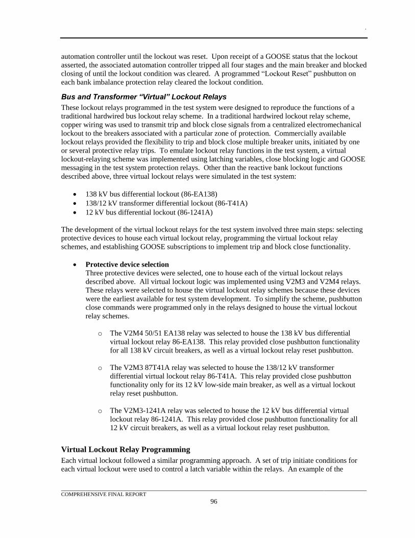
.
COMPREHENSIVE FINAL REPORT
96
automation controller until the lockout was reset. Upon receipt of a GOOSE status that the lockout
asserted, the associated automation controller tripped all four stages and the main breaker and blocked
closing of until the lockout condition was cleared. A programmed “Lockout Reset” pushbutton on
each bank imbalance protection relay cleared the lockout condition.
Bus and Transformer “Virtual” Lockout Relays
These lockout relays programmed in the test system were designed to reproduce the functions of a
traditional hardwired bus lockout relay scheme. In a traditional hardwired lockout relay scheme,
copper wiring was used to transmit trip and block close signals from a centralized electromechanical
lockout to the breakers associated with a particular zone of protection. Commercially available
lockout relays provided the flexibility to trip and block close multiple breaker units, initiated by one
or several protective relay trips. To emulate lockout relay functions in the test system, a virtual
lockout-relaying scheme was implemented using latching variables, close blocking logic and GOOSE
messaging in the test system protection relays. Other than the reactive bank lockout functions
described above, three virtual lockout relays were simulated in the test system:
• 138 kV bus differential lockout (86-EA138)
• 138/12 kV transformer differential lockout (86-T41A)
• 12 kV bus differential lockout (86-1241A)
The development of the virtual lockout relays for the test system involved three main steps: selecting
protective devices to house each virtual lockout relay, programming the virtual lockout relay
schemes, and establishing GOOSE subscriptions to implement trip and block close functionality.
• Protective device selection
Three protective devices were selected, one to house each of the virtual lockout relays
described above. All virtual lockout logic was implemented using V2M3 and V2M4 relays.
These relays were selected to house the virtual lockout relay schemes because these devices
were the earliest available for test system development. To simplify the scheme, pushbutton
close commands were programmed only in the relays designed to house the virtual lockout
relay schemes.
o The V2M4 50/51 EA138 relay was selected to house the 138 kV bus differential
virtual lockout relay 86-EA138. This relay provided close pushbutton functionality
for all 138 kV circuit breakers, as well as a virtual lockout relay reset pushbutton.
o The V2M3 87T41A relay was selected to house the 138/12 kV transformer
differential virtual lockout relay 86-T41A. This relay provided close pushbutton
functionality only for its 12 kV low-side main breaker, as well as a virtual lockout
relay reset pushbutton.
o The V2M3-1241A relay was selected to house the 12 kV bus differential virtual
lockout relay 86-1241A. This relay provided close pushbutton functionality for all
12 kV circuit breakers, as well as a virtual lockout relay reset pushbutton.
Virtual Lockout Relay Programming
Each virtual lockout followed a similar programming approach. A set of trip initiate conditions for
each virtual lockout were used to control a latch variable within the relays. An example of the
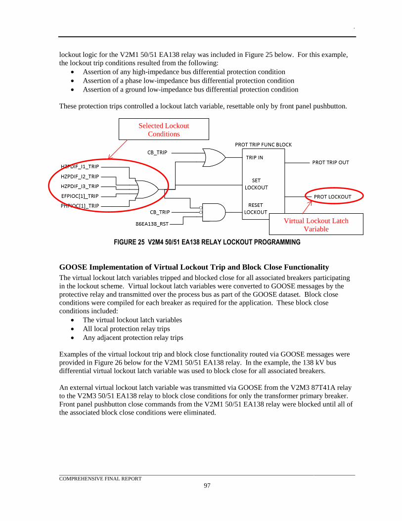
.
COMPREHENSIVE FINAL REPORT
97
lockout logic for the V2M1 50/51 EA138 relay was included in Figure 25 below. For this example,
the lockout trip conditions resulted from the following:
• Assertion of any high-impedance bus differential protection condition
• Assertion of a phase low-impedance bus differential protection condition
• Assertion of a ground low-impedance bus differential protection condition
These protection trips controlled a lockout latch variable, resettable only by front panel pushbutton.
FIGURE 25 V2M4 50/51 EA138 RELAY LOCKOUT PROGRAMMING
GOOSE Implementation of Virtual Lockout Trip and Block Close Functionality
The virtual lockout latch variables tripped and blocked close for all associated breakers participating
in the lockout scheme. Virtual lockout latch variables were converted to GOOSE messages by the
protective relay and transmitted over the process bus as part of the GOOSE dataset. Block close
conditions were compiled for each breaker as required for the application. These block close
conditions included:
• The virtual lockout latch variables
• All local protection relay trips
• Any adjacent protection relay trips
Examples of the virtual lockout trip and block close functionality routed via GOOSE messages were
provided in Figure 26 below for the V2M1 50/51 EA138 relay. In the example, the 138 kV bus
differential virtual lockout latch variable was used to block close for all associated breakers.
An external virtual lockout latch variable was transmitted via GOOSE from the V2M3 87T41A relay
to the V2M3 50/51 EA138 relay to block close conditions for only the transformer primary breaker.
Front panel pushbutton close commands from the V2M1 50/51 EA138 relay were blocked until all of
the associated block close conditions were eliminated.
Selected Lockout
Conditions
Virtual Lockout Latch
Variable
.
COMPREHENSIVE FINAL REPORT
98
FIGURE 26 V2M4 50/51 EA138 RELAY BLOCK CLOSE PROGRAMMING
Interoperability
Investigation into interoperability was the most challenging experience when designing the test
system. Although the Utility Communications Architecture International Users Group (UCAIug)
issued an implementation guide in 2006, the recent advent of edition 2 created interoperability issues
as the manufacturers migrated to the revised standard.
It was noted that even though manufacturers claimed support for IEC 61850-9-2LE (Light Edition) in
both edition 1 or 2, there were differences from the LE document. It appeared that manufacturers
picked what they determined were the important aspects of the LE document and only implemented
those in their edition 2 products. In some cases this caused an incompatibility problem between SV
publishers and subscribers.
Most of the manufacturers moved to implement edition 2 features while attempting to maintain the
LE compliance with edition 1. Some manufacturers strictly enforced some of the items and made
changes in others in order to accommodate both edition 1 and 2. The use of the SmpSynch field in
the SV message buffering and the SV AppID were the two most noticeable items. The SmpSynch
definition and data type was changed in edition 2. One merging unit strictly used the LE
implementation for this field and it did not work with a protection device that strictly used the IEC
61850 Edition 2 implementation.
The use of GOOSE messaging between editions did not present a problem, and the ease in setting up
relay logic for these signals with the current manufacturer software was greatly improved over
experiences from just a few years ago. Configuration software included function blocks, directly tied
to the IEC 61850 configurations, which could be re-used to quickly build relay logic functions. The
only modification made in edition 2 was to change the “test field” to a “simulation field”. This field
was not utilized in the test system. For the test system, edition 1 and 2 devices could function with
both message types. It was determined that half the merging units had only implemented edition 2
GOOSE along with some of the protection relays. The exception was the capacitor and reactor
automation controllers which only supported edition 1 GOOSE. There were no problems in
implementing GOOSE solutions for the test system but since every other device supported edition 2,
the projects was based on edition 2.
Block Close from
Transformer Virtual Lockout
86-T41A
Block Close for Adjacent
Protection Trips
.
COMPREHENSIVE FINAL REPORT
99
SCL file schemes and structures changed in edition 2. Some manufacturers’ configuration tools
accepted both edition 1 and 2 files while others required that the edition be declared at the start of a
project and would then only accepts files from the declared edition. From the matrices, in TABLE 16
and Table 17, it was determined that all of the software tools would accept edition 2 files versus
edition 1 files, which greatly impacted the decision to create the project as an edition 2 project.
.
COMPREHENSIVE FINAL REPORT
100
10. TEST PROCEDURES The demonstration plan was developed to ensure that each test case and its associated tests were
performed and documented. Test case plan development was based on traditional relay testing plans.
For each test case, a description of the case was included to describe the test configuration and
success criteria. Test set-up conditions described the relays under test and the protection functions to
be evaluated.
The source of the relay settings is then described and the relevant portion of the RTDS model is
indicated. This section 10 also describes how the trip and close signals were transmitted. Finally, the
test case performance tests are described with individual actions for each step. Captured wave forms,
digital point statuses and contact operations are illustrated using COMTRADE plots and a graphical
event analyzer. These files illustrate the raw data that was used to populate the results within the
plan. Also included is a summary of all the operating times for each fault simulation.
Each test case was carefully designed to emulate real world scenarios. Here the configuration and
setup of individual test cases were examined in detail. Relay protection settings and system voltage
and current characteristics were explained. Finally, the raw performance data resulting from the
simulation by the test set, which was extracted from the protection relays, was analyzed. These files
were included in Appendix F.
Performance tests demonstrate proper operation of the test bed setup and relay settings, and record
performance result data for the test cases. Tripping of circuit breakers was simulated by latching
relays connected to MU digital outputs. Critical timing and observed element operation was recorded
and included in Appendix G.
Test Case #1 – Breaker Failure Protection (50BF)
Relay Test Setup Conditions and Requirements
1. The test was performed on one manufacturer’s high-performance breaker-failure numerical
relay.
a. The selected relay evaluated was:
i. Mfg./Model V1M2 breaker failure/control relay
2. Backup line distance (21) and directional overcurrent protection (50/51) element performance
was evaluated in a separate test case test from breaker failure so as to produce distinct results
for the protection test case analysis.
3. Distance and directional overcurrent element settings matched those installed in the identified
substation relays as much as possible.
4. For pre-commercial demonstration, an RTDS model of the identified substation, using
equivalents to represent the system beyond the remote substation buses, was used to generate
COMTRADE data files for each line node for playback by relay test sets. The secondary
current and voltage playback signals were connected to the appropriate MUs and relay analog
inputs. COMTRADE results for this test are included in Appendix F with the file names
described in Section 6.
5. Trip and close signals to the breakers were via GOOSE messages to the appropriate MUs,
and the breakers were simulated by latching relays. Programmable pushbuttons on the
protective relays were configured to simulate manual trip and close logic to represent panel
mounted control switches.
.
COMPREHENSIVE FINAL REPORT
101
Test Case Voltage and Current Injection from Relay Test Sets
1. MU1 (69/138 kV line CB 2)
a. Mfg./Model V1M5
b. CTR= 400T
c. PTR= 700T (W. bus)
50BF Performance Tests (Mfg./Model V1M2)
1. Simulate a 3LG fault close-in to the breaker by COMTRADE playback injection with CB 2
breaker current not dropping out and record the following:
a. Download event record from each relay
b. Fault Initiation Time: 6:10:7.110 PM**
c. 50BF Relay Fault Recorder Initiation Time: 6:10:7.116 PM
d. 50BF GOOSE BFI Received Time: 6:10:7.116 PM (50BF element pickup)
e. Relay 50BF Trip Time: 6:10:7.496 PM
f. CB 2 52a Open Detected Time: 6:10:7.561 PM
g. CB 7 52a Open Detected Time: 6:10:7.550 PM
h. CB 3 52a Open Detected Time: 6:10:7.547 PM
i. Comments: 62BF set @ 0.417s (25 cycles)
2. Simulate a 3LG fault close-in to the breaker by COMTRADE playback injection with CB 2
breaker 52a status contact not dropping out and record the following:
a. Download event record from each relay
b. Fault Initiation Time: 6:19:01.110 PM
c. 50BF Relay Fault Initiation Time: 6:19:01.116 PM
d. 50BF GOOSE BFI Received Time: 6:19:01.116 PM (50BF element pickup)
e. Relay 50BF Trip Initiation Time: 6:19:01.496 PM
f. CB 2 52a Open Detected Time: 6:19:01.561 PM
g. CB 7 52a Open Detected Time: 6:19:01.550 PM
h. CB 3 52a Open Detected Time: 6:19:01.547 PM
i. Comments: 62BF set @ 0.417s (25 cycles)
**Note: All times listed in the report were in GMT, which was the master simulations test-system
setting.
Test Case #2 – Line Differential Protection (87L)
Relay Test Setup Conditions and Requirements
1. The tests were performed on two different manufacturers’ high-performance numerical line
differential relays that also incorporated backup impedance and directional overcurrent
tripping elements. The selected relays to be evaluated were:
a. Set A – Mfg./Model V2M2
b. Set B – Mfg./Model V1M1
2. Backup line distance (21) and directional overcurrent protection (50/51) element performance
was evaluated in a separate test case test from line differential (87L) so as to produce distinct
results for protection test case analysis.
3. Differential protection communications was via an industry standard IEEE C37.94, 64 kB
channel that connected the local and remote simulation relays via a multi-mode (MM) fiber-
optic jumper. As the communications channel effect on relaying performance was not under
.
COMPREHENSIVE FINAL REPORT
102
study, a direct fiber-optic connection without multiplex or transmission delay was assumed
for the test.
4. Differential element settings matched those installed in the identified substation relays as
much as possible.
5. For pre-commercial demonstration, an RTDS model of the identified substation, using
equivalents to represent the system beyond the remote substation buses, was used to generate
COMTRADE data files for each line node for playback by relay test sets. The secondary
current and voltage playback signals were connected to the appropriate MUs and relay analog
inputs. COMTRADE results for this test are included in Appendix F with the file names
described in Section 6.
6. Trip and close signals to the breakers were via GOOSE messages to the appropriate MUs,
and the breakers were simulated by latching relays. Programmable pushbuttons on the
protective relays were configured to simulate manual trip and close logic to represent panel
mounted control switches.
Test case voltage and current injection from relay test sets
1. MU1 69/138 kV Line CB 2) for local relays
a. Mfg./Model V1M5
b. CTR= 400T
c. PTR= 700T (W. bus)
2. Direct connection to Set A and B remote relays
Set A 87L Performance Tests (Mfg./Model V2M2)
1. Simulate a 3LG fault behind the local 87L Set A by COMTRADE playback injection and
record the following:
a. Local Relay 87L Element Restrained? (Yes/No): Yes
b. Local Relay 87L Element Restrained? (Yes/No): Yes
c. Comments: None – proper operation, no event records triggered in local relay
2. Simulate a 1LG fault behind the local 87L Set A by COMTRADE playback injection and
record the following:
a. Local Relay 87L Element Restrained? (Yes/No): Yes
b. Local Relay 87L Element Restrained? (Yes/No): Yes
c. Comments: None – proper operation, no event records triggered in local relay
3. Simulate a 3LG fault close-in to the local 87L Set A by COMTRADE playback injection and
record the following:
a. Download event records from the relays at each line end
b. Fault Initiation Time: 9:52:00.532 PM
c. Local Relay 87L Trip Initiation Time: 9:52:00.543 PM
d. Remote Relay 87L Trip Initiation Time: 9:52:00.543 PM
e. Local Relay 52a Open Detected Time: 9:52:00.565 PM
f. Comments: True sub-cycle relay operation
4. Simulate a 1LG fault close-in to the local 87L Set A by COMTRADE playback injection and
record the following:
a. Download event records from the relays at each line end
.
COMPREHENSIVE FINAL REPORT
103
b. Fault Initiation Time: 10:14:30.534 PM
c. Local Relay 87L Trip Initiation Time: 10:14:30.549 PM
d. Remote Relay 87L Trip Initiation Time: 10:14:30.545 PM
e. Local Relay 52a Open Detected Time: 10:14:30.565 PM
f. Comments: True sub-cycle relay operation
5. Simulate a 3LG fault behind the remote 87L Set A by COMTRADE playback injection and
record the following:
a. Local Relay 87L Element Restrained? (Yes/No): Yes
b. Local Relay 87L Element Restrained? (Yes/No): Yes
c. Comments: None – proper operation, event triggered by overreaching distance
protection
6. Simulate a 1LG fault behind the remote 87L Set A by COMTRADE playback injection and
record the following:
a. Local Relay 87L Element Restrained? (Yes/No): Yes
b. Local Relay 87L Element Restrained? (Yes/No): Yes
c. Comments: None – proper operation, event triggered by overreaching distance
protection
Set B 87L Performance Tests (Mfg./Model V1M1)
1. Simulate a 3LG fault behind the local 87L Set A by COMTRADE playback injection and
record the following:
a. Local Relay 87L Element Restrained? (Yes/No): Yes
b. Local Relay 87L Element Restrained? (Yes/No): Yes
c. Comments: None – proper operation, no event records triggered in local relay
2. Simulate a 1LG fault behind the local 87L Set A by COMTRADE playback injection and
record the following:
a. Local Relay 87L Element Restrained? (Yes/No): Yes
b. Local Relay 87L Element Restrained? (Yes/No): Yes
c. Comments: None – proper operation, no event records triggered in local relay
3. Simulate a 3LG fault close-in to the local 87L Set A by COMTRADE playback injection and
record the following:
a. Download event records from the relays at each line end
b. Fault Initiation Time: 7:05:00.492 PM
c. Local Relay 87L Trip Initiation Time: 7:05:00.517 PM
d. Remote Relay 87L Trip Initiation Time: 7:05:00.519 PM
e. Local Relay 52a Open Detected Time: 7:05:00.567 PM
f. Comments: 1.4 cycle relay operation – this was slow for a high-end 87L relay
4. Simulate a 1LG fault close-in to the local 87L Set A by COMTRADE playback injection and
record the following:
a. Download event records from the relays at each line end
b. Fault Initiation Time: 6:55:30.492 PM
c. Local Relay 87L Trip Initiation Time: 6:55:30.515 PM
d. Remote Relay 87L Trip Initiation Time: 6:55:30.523 PM
e. Local Relay 52a Open Detected Time: 6:55:30.569 PM
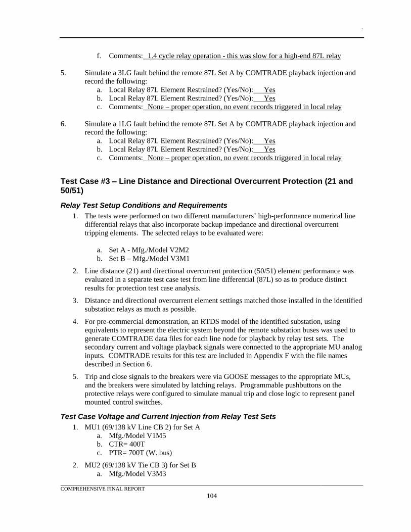
.
COMPREHENSIVE FINAL REPORT
104
f. Comments: 1.4 cycle relay operation - this was slow for a high-end 87L relay
5. Simulate a 3LG fault behind the remote 87L Set A by COMTRADE playback injection and
record the following:
a. Local Relay 87L Element Restrained? (Yes/No): Yes
b. Local Relay 87L Element Restrained? (Yes/No): Yes
c. Comments: None – proper operation, no event records triggered in local relay
6. Simulate a 1LG fault behind the remote 87L Set A by COMTRADE playback injection and
record the following:
a. Local Relay 87L Element Restrained? (Yes/No): Yes
b. Local Relay 87L Element Restrained? (Yes/No): Yes
c. Comments: None – proper operation, no event records triggered in local relay
Test Case #3 – Line Distance and Directional Overcurrent Protection (21 and 50/51)
Relay Test Setup Conditions and Requirements
1. The tests were performed on two different manufacturers’ high-performance numerical line
differential relays that also incorporate backup impedance and directional overcurrent
tripping elements. The selected relays to be evaluated were:
a. Set A - Mfg./Model V2M2
b. Set B – Mfg./Model V3M1
2. Line distance (21) and directional overcurrent protection (50/51) element performance was
evaluated in a separate test case test from line differential (87L) so as to produce distinct
results for protection test case analysis.
3. Distance and directional overcurrent element settings matched those installed in the identified
substation relays as much as possible.
4. For pre-commercial demonstration, an RTDS model of the identified substation, using
equivalents to represent the electric system beyond the remote substation buses was used to
generate COMTRADE data files for each line node for playback by relay test sets. The
secondary current and voltage playback signals were connected to the appropriate MU analog
inputs. COMTRADE results for this test are included in Appendix F with the file names
described in Section 6.
5. Trip and close signals to the breakers were via GOOSE messages to the appropriate MUs,
and the breakers were simulated by latching relays. Programmable pushbuttons on the
protective relays were configured to simulate manual trip and close logic to represent panel
mounted control switches.
Test Case Voltage and Current Injection from Relay Test Sets
1. MU1 (69/138 kV Line CB 2) for Set A
a. Mfg./Model V1M5
b. CTR= 400T
c. PTR= 700T (W. bus)
2. MU2 (69/138 kV Tie CB 3) for Set B
a. Mfg./Model V3M3
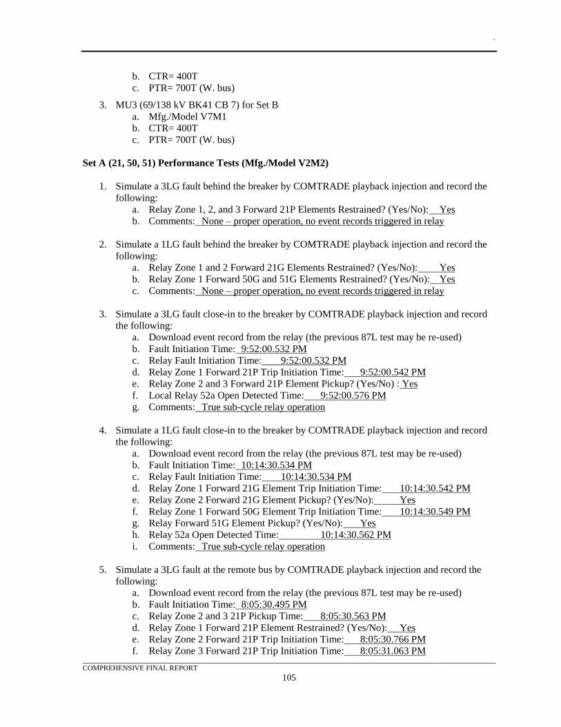
.
COMPREHENSIVE FINAL REPORT
105
b. CTR= 400T
c. PTR= 700T (W. bus)
3. MU3 (69/138 kV BK41 CB 7) for Set B
a. Mfg./Model V7M1
b. CTR= 400T
c. PTR= 700T (W. bus)
Set A (21, 50, 51) Performance Tests (Mfg./Model V2M2)
1. Simulate a 3LG fault behind the breaker by COMTRADE playback injection and record the
following:
a. Relay Zone 1, 2, and 3 Forward 21P Elements Restrained? (Yes/No): Yes
b. Comments: None – proper operation, no event records triggered in relay
2. Simulate a 1LG fault behind the breaker by COMTRADE playback injection and record the
following:
a. Relay Zone 1 and 2 Forward 21G Elements Restrained? (Yes/No): Yes
b. Relay Zone 1 Forward 50G and 51G Elements Restrained? (Yes/No): Yes
c. Comments: None – proper operation, no event records triggered in relay
3. Simulate a 3LG fault close-in to the breaker by COMTRADE playback injection and record
the following:
a. Download event record from the relay (the previous 87L test may be re-used)
b. Fault Initiation Time: 9:52:00.532 PM
c. Relay Fault Initiation Time: 9:52:00.532 PM
d. Relay Zone 1 Forward 21P Trip Initiation Time: 9:52:00.542 PM
e. Relay Zone 2 and 3 Forward 21P Element Pickup? (Yes/No) : Yes
f. Local Relay 52a Open Detected Time: 9:52:00.576 PM
g. Comments: True sub-cycle relay operation
4. Simulate a 1LG fault close-in to the breaker by COMTRADE playback injection and record
the following:
a. Download event record from the relay (the previous 87L test may be re-used)
b. Fault Initiation Time: 10:14:30.534 PM
c. Relay Fault Initiation Time: 10:14:30.534 PM
d. Relay Zone 1 Forward 21G Element Trip Initiation Time: 10:14:30.542 PM
e. Relay Zone 2 Forward 21G Element Pickup? (Yes/No): Yes
f. Relay Zone 1 Forward 50G Element Trip Initiation Time: 10:14:30.549 PM
g. Relay Forward 51G Element Pickup? (Yes/No): Yes
h. Relay 52a Open Detected Time: 10:14:30.562 PM
i. Comments: True sub-cycle relay operation
5. Simulate a 3LG fault at the remote bus by COMTRADE playback injection and record the
following:
a. Download event record from the relay (the previous 87L test may be re-used)
b. Fault Initiation Time: 8:05:30.495 PM
c. Relay Zone 2 and 3 21P Pickup Time: 8:05:30.563 PM
d. Relay Zone 1 Forward 21P Element Restrained? (Yes/No): Yes
e. Relay Zone 2 Forward 21P Trip Initiation Time: 8:05:30.766 PM
f. Relay Zone 3 Forward 21P Trip Initiation Time: 8:05:31.063 PM
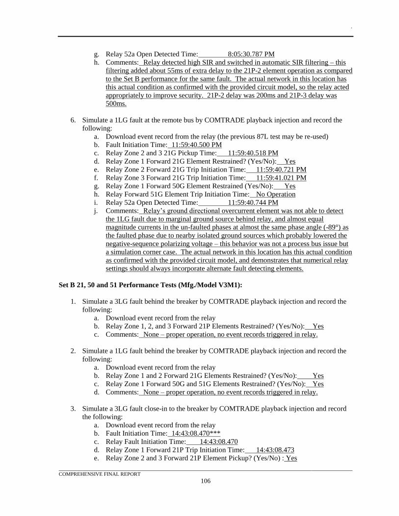
.
COMPREHENSIVE FINAL REPORT
106
g. Relay 52a Open Detected Time: 8:05:30.787 PM
h. Comments: Relay detected high SIR and switched in automatic SIR filtering – this
filtering added about 55ms of extra delay to the 21P-2 element operation as compared
to the Set B performance for the same fault. The actual network in this location has
this actual condition as confirmed with the provided circuit model, so the relay acted
appropriately to improve security. 21P-2 delay was 200ms and 21P-3 delay was
500ms.
6. Simulate a 1LG fault at the remote bus by COMTRADE playback injection and record the
following:
a. Download event record from the relay (the previous 87L test may be re-used)
b. Fault Initiation Time: 11:59:40.500 PM
c. Relay Zone 2 and 3 21G Pickup Time: 11:59:40.518 PM
d. Relay Zone 1 Forward 21G Element Restrained? (Yes/No): Yes
e. Relay Zone 2 Forward 21G Trip Initiation Time: 11:59:40.721 PM
f. Relay Zone 3 Forward 21G Trip Initiation Time: 11:59:41.021 PM
g. Relay Zone 1 Forward 50G Element Restrained (Yes/No): Yes
h. Relay Forward 51G Element Trip Initiation Time: No Operation
i. Relay 52a Open Detected Time: 11:59:40.744 PM
j. Comments: Relay’s ground directional overcurrent element was not able to detect
the 1LG fault due to marginal ground source behind relay, and almost equal
magnitude currents in the un-faulted phases at almost the same phase angle (-89°) as
the faulted phase due to nearby isolated ground sources which probably lowered the
negative-sequence polarizing voltage – this behavior was not a process bus issue but
a simulation corner case. The actual network in this location has this actual condition
as confirmed with the provided circuit model, and demonstrates that numerical relay
settings should always incorporate alternate fault detecting elements.
Set B 21, 50 and 51 Performance Tests (Mfg./Model V3M1):
1. Simulate a 3LG fault behind the breaker by COMTRADE playback injection and record the
following:
a. Download event record from the relay
b. Relay Zone 1, 2, and 3 Forward 21P Elements Restrained? (Yes/No): Yes
c. Comments: None – proper operation, no event records triggered in relay.
2. Simulate a 1LG fault behind the breaker by COMTRADE playback injection and record the
following:
a. Download event record from the relay
b. Relay Zone 1 and 2 Forward 21G Elements Restrained? (Yes/No): Yes
c. Relay Zone 1 Forward 50G and 51G Elements Restrained? (Yes/No): Yes
d. Comments: None – proper operation, no event records triggered in relay.
3. Simulate a 3LG fault close-in to the breaker by COMTRADE playback injection and record
the following:
a. Download event record from the relay
b. Fault Initiation Time: 14:43:08.470***
c. Relay Fault Initiation Time: 14:43:08.470
d. Relay Zone 1 Forward 21P Trip Initiation Time: 14:43:08.473
e. Relay Zone 2 and 3 Forward 21P Element Pickup? (Yes/No) : Yes
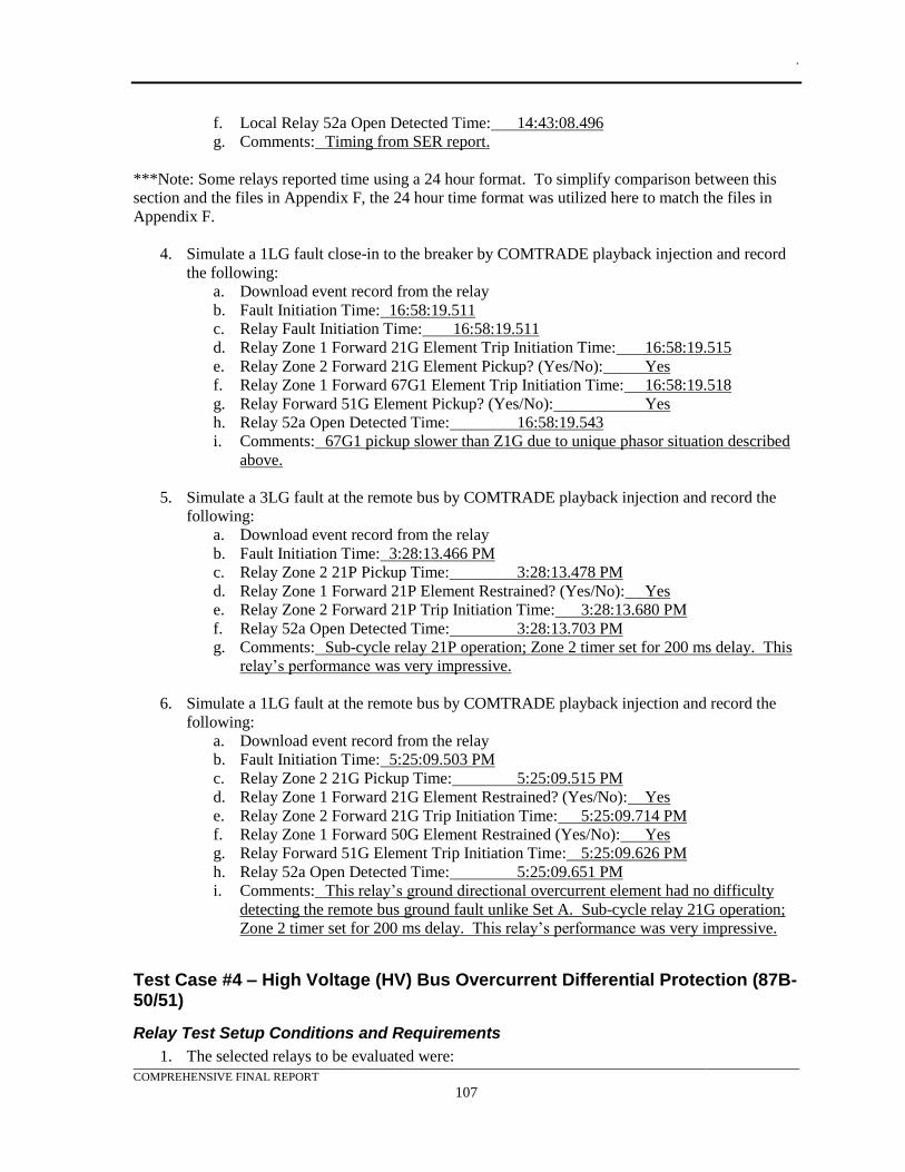
.
COMPREHENSIVE FINAL REPORT
107
f. Local Relay 52a Open Detected Time: 14:43:08.496
g. Comments: Timing from SER report.
***Note: Some relays reported time using a 24 hour format. To simplify comparison between this
section and the files in Appendix F, the 24 hour time format was utilized here to match the files in
Appendix F.
4. Simulate a 1LG fault close-in to the breaker by COMTRADE playback injection and record
the following:
a. Download event record from the relay
b. Fault Initiation Time: 16:58:19.511
c. Relay Fault Initiation Time: 16:58:19.511
d. Relay Zone 1 Forward 21G Element Trip Initiation Time: 16:58:19.515
e. Relay Zone 2 Forward 21G Element Pickup? (Yes/No): Yes
f. Relay Zone 1 Forward 67G1 Element Trip Initiation Time: 16:58:19.518
g. Relay Forward 51G Element Pickup? (Yes/No): Yes
h. Relay 52a Open Detected Time: 16:58:19.543
i. Comments: 67G1 pickup slower than Z1G due to unique phasor situation described
above.
5. Simulate a 3LG fault at the remote bus by COMTRADE playback injection and record the
following:
a. Download event record from the relay
b. Fault Initiation Time: 3:28:13.466 PM
c. Relay Zone 2 21P Pickup Time: 3:28:13.478 PM
d. Relay Zone 1 Forward 21P Element Restrained? (Yes/No): Yes
e. Relay Zone 2 Forward 21P Trip Initiation Time: 3:28:13.680 PM
f. Relay 52a Open Detected Time: 3:28:13.703 PM
g. Comments: Sub-cycle relay 21P operation; Zone 2 timer set for 200 ms delay. This
relay’s performance was very impressive.
6. Simulate a 1LG fault at the remote bus by COMTRADE playback injection and record the
following:
a. Download event record from the relay
b. Fault Initiation Time: 5:25:09.503 PM
c. Relay Zone 2 21G Pickup Time: 5:25:09.515 PM
d. Relay Zone 1 Forward 21G Element Restrained? (Yes/No): Yes
e. Relay Zone 2 Forward 21G Trip Initiation Time: 5:25:09.714 PM
f. Relay Zone 1 Forward 50G Element Restrained (Yes/No): Yes
g. Relay Forward 51G Element Trip Initiation Time: 5:25:09.626 PM
h. Relay 52a Open Detected Time: 5:25:09.651 PM
i. Comments: This relay’s ground directional overcurrent element had no difficulty
detecting the remote bus ground fault unlike Set A. Sub-cycle relay 21G operation;
Zone 2 timer set for 200 ms delay. This relay’s performance was very impressive.
Test Case #4 – High Voltage (HV) Bus Overcurrent Differential Protection (87B-50/51)
Relay Test Setup Conditions and Requirements
1. The selected relays to be evaluated were:
.
COMPREHENSIVE FINAL REPORT
108
a. Set A - Mfg./Model V2M1
b. Set B - Mfg./Model V1M3
2. Overcurrent differential element settings matched those installed in the identified substation
relays as much as possible.
3. For pre-commercial demonstration, an RTDS model of the identified substation, using
equivalents to represent the electric system beyond the remote substation buses was used to
generate COMTRADE data files for each line node for playback by relay test sets. The
secondary current and voltage playback signals were connected to the appropriate MU analog
inputs. COMTRADE results for this test are included in Appendix F with the file names
described in Section 6.
4. Trip and close signals to the breakers were via GOOSE messages to the appropriate MUs,
and the breakers were simulated by latching relays. Programmable pushbuttons on the
protective relays were configured to simulate manual trip and close logic to represent panel
mounted control switches.
Test Case Voltage and Current Injection from Relay Test Sets
1. MU1 (69/138 kV Line CB 2)
a. Mfg./Model V1M5
b. CTR= 400T
c. PTR= 700T (W. bus)
2. MU2 (69/138 kV Tie CB 3)
a. Mfg./Model V3M3
b. CTR= 400T
c. PTR= 700T (W. bus)
3. MU3 (69/138 kV BK41 CB 7)
a. Mfg./Model V7M1
b. CTR= 400T
c. PTR= 700T (W. bus)
Set A 87B-50/51 Overcurrent Differential Performance Tests (Mfg./Model V2M1)
1. Simulate a close-in 3LG fault on the transmission line by COMTRADE playback injection
and record the following:
a. Relay 87B-50/51 Restrained? (Yes/No): Yes
b. Comments: None – proper relay operation
2. Simulate a close-in 1LG fault on the transmission line by COMTRADE playback injection
and record the following:
a. Relay 87B-50/51 Restrained? (Yes/No): Yes
b. Comments: None – proper relay operation
3. Simulate a 3LG fault on the HV bus by COMTRADE playback injection and record the
following:
a. Download event record from the relay
b. Fault Initiation Time: 2:55:00.495 PM
c. Relay Fault Initiation Time: 2:55:00.500 PM
.
COMPREHENSIVE FINAL REPORT
109
d. Relay 87B-50P Trip Initiation Time: 2:55:00.500 PM
e. Relay Longest 52a Open Detected Time: 2:55:00.528 PM
f. Comments: Excellent sub-cycle operation.
4. Simulate a 1LG fault on the HV bus by COMTRADE playback injection and record the
following:
a. Download event record from the relay
b. Fault Initiation Time: 3:34:11.504 PM
c. Relay Fault Initiation Time: 3:34:11.509 PM
d. Relay 87B-50/51Trip Initiation Time: 3:34:11.509 PM
e. Relay Longest 52a Open Detected Time: 3:34:11.535 PM
f. Comments: Excellent sub-cycle operation.
Set B 87B-50/51 Overcurrent Differential Performance Tests (Mfg./Model V1M3)
1. Simulate a 3LG fault on the transmission line by COMTRADE playback injection and record
the following:
a. Relay 87B-50/51 Restrained? (Yes/No): Yes
b. Comments: None – proper relay operation.
2. Simulate an SLG fault on the transmission line by COMTRADE playback injection and
record the following:
a. Relay Differential Overcurrent Restrained? (Yes/No): Yes
b. Comments: None – proper relay operation.
3. Simulate a 3LG fault on the HV bus by COMTRADE playback injection and record the
following:
a. Download event record from the relay
b. Fault Initiation Time: 3:55:00.500 PM
c. Relay Fault Initiation Time: 3:55:00.504 PM
d. Relay 87B-50P Trip Initiation Time: 3:55:00.504 PM
e. Relay 52a Open Detected Time: 3:55:00.534 PM
f. Comments: Excellent sub-cycle operation.
4. Simulate an SLG fault on the HV bus by COMTRADE playback injection and record the
following:
a. Download event record from the relay
b. Fault Initiation Time: 4:10:00.495 PM
c. Relay Fault Initiation Time: 4:10:00.503 PM
d. Relay 87B-50G Trip Initiation Time: 4:10:00.503 PM
e. Relay 52a Open Detected Time: 4:10:00.533 PM
f. Comments: Excellent sub-cycle operation.
Test Case #5 – HV Bus Restrained Current Differential Protection (87B)
Relay Test Setup Conditions and Requirements
1. The selected relay to be evaluated were:
a. Mfg./Model V1M3
.
COMPREHENSIVE FINAL REPORT
110
2. Existing distribution substations and standards did not use overcurrent differential protection
for this application, so settings did not match those installed in the identified substation
relays; typical industry standard settings were applied.
3. For pre-commercial demonstration, an RTDS model of the identified substation using,
equivalents to represent the electric system beyond the remote substation buses was used to
generate COMTRADE data files for each line node for playback by relay test sets. The
secondary current and voltage playback signals were connected to the appropriate MU analog
inputs. COMTRADE results for this test are included in Appendix F with the file names
described in Section 6.
4. Trip and close signals to the breakers were via GOOSE messages to the appropriate MUs,
and the breakers were simulated by latching relays. Programmable pushbuttons on the
protective relays were configured to simulate manual trip and close logic to represent panel
mounted control switches.
Test Case Voltage and Current Injection from Relay Test Sets
1. MU1 (69/138 kV Line CB 2)
a. Mfg./Model V1M5
b. CTR= 400T
c. PTR= 700T (W. bus)
2. MU2 (69/138 kV Tie CB 3)
a. Mfg./Model V3M3
b. CTR= 400T
c. PTR= 700T (W. bus)
3. MU3 (69/138 kV BK41 CB 7)
a. Mfg./Model V7M1
b. CTR= 400T
c. PTR= 700T (W. bus)
87B Restrained Current Differential Performance Tests (Mfg./Model V1M3)
1. Simulate a close-in 3LG fault on the transmission line by COMTRADE playback injection
and record the following:
a. Relay Differential Overcurrent Restrained? (Yes/No): Yes
b. Comments: None – proper relay operation.
2. Simulate a close-in 1LG fault on the transmission line by COMTRADE playback injection
and record the following:
a. Relay Differential Overcurrent Restrained? (Yes/No): Yes
b. Comments: None – proper relay operation.
3. Simulate a 3LG fault on the HV bus by COMTRADE playback injection and record the
following:
a. Download event record from the relay
b. Fault Initiation Time: 3:55:00.500 PM
c. Relay Fault Initiation Time: 3:55:00.504 PM
d. Relay 87B Trip Initiation Time: 3:55:00.504 PM
.
COMPREHENSIVE FINAL REPORT
111
e. Relay 52a Open Detected Time: 3:55:00.534 PM
f. Comments: Excellent sub-cycle operation.
4. Simulate a 1LG fault on the HV bus by COMTRADE playback injection and record the
following:
a. Download event record from the relay
b. Fault Initiation Time: 4:10:00.495 PM
c. Relay Fault Initiation Time: 4:10:00.503 PM
d. Relay Trip Initiation Time: 4:10:00.503 PM
e. Relay 52a Open Detected Time: 4:10:00.533 PM
f. Comments: Excellent sub-cycle operation.
Test Case #6 – HV Bus High Impedance Differential Protection (87B-HIZ)
Relay Test Setup Conditions and Requirements
1. The selected relay to be evaluated was:
a. Mfg./Model V2M4
2. Existing distribution substations and standards did not use high-impedance differential
protection for this application, so settings do not match those installed in the identified
substation relays; typical industry standard settings were applied.
3. For pre-commercial demonstration, an RTDS model of the identified substation, using
equivalents to represent the system beyond the remote substation buses was used to generate
COMTRADE data files for each line node for playback by relay test sets. The secondary
current signals from the breakers bounding the differential zone were summed together in the
model and the output of this summation was connected to the MU analog input.
COMTRADE results for this test are included in Appendix F with the file names described in
Section 6.
4. Trip and close signals to the breakers were via GOOSE messages to the appropriate MUs,
and the breakers were simulated by latching relays. Programmable pushbuttons on the
protective relays were configured to simulate manual trip and close logic to represent panel
mounted control switches.
Test Case Voltage and Current Injection from Relay Test Sets
1. MU12 (69/138 kV Line CB 2, CB3, CB7 summed externally in a High Impedance (HIZ)
resistor assembly made by Mfg. V2)
a. Mfg./Model V3M3
b. CTR= Special Setting based on chosen resistor setting – see relay settings
documentation
c. PTR= 700T (W. bus)
87B-HIZ High Impedance Bus Differential Performance Tests (Mfg./Model V2M4)
1. Simulate a 3LG fault on the transmission line by COMTRADE playback injection and record
the following:
a. Relay 87B-HIZ Restrained? (Yes/No): Yes
b. Comments: Test simulated by direct MU current injection from F6150e as resistor
assembly was not available.
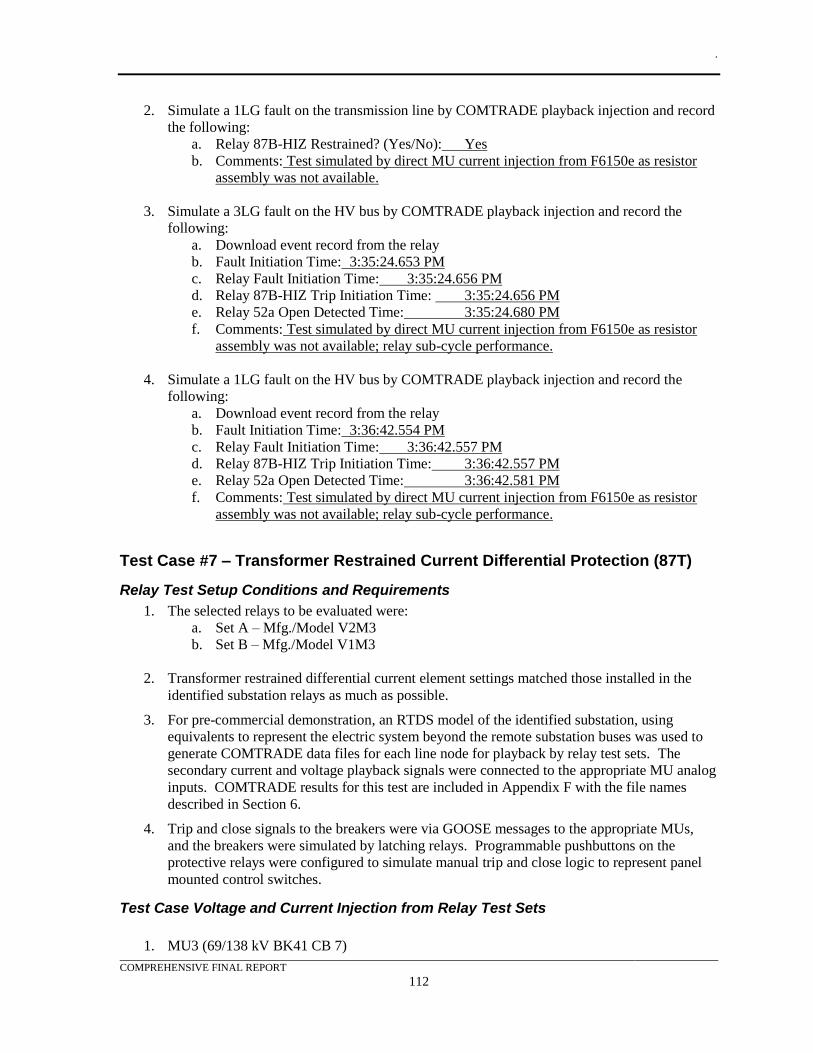
.
COMPREHENSIVE FINAL REPORT
112
2. Simulate a 1LG fault on the transmission line by COMTRADE playback injection and record
the following:
a. Relay 87B-HIZ Restrained? (Yes/No): Yes
b. Comments: Test simulated by direct MU current injection from F6150e as resistor
assembly was not available.
3. Simulate a 3LG fault on the HV bus by COMTRADE playback injection and record the
following:
a. Download event record from the relay
b. Fault Initiation Time: 3:35:24.653 PM
c. Relay Fault Initiation Time: 3:35:24.656 PM
d. Relay 87B-HIZ Trip Initiation Time: 3:35:24.656 PM
e. Relay 52a Open Detected Time: 3:35:24.680 PM
f. Comments: Test simulated by direct MU current injection from F6150e as resistor
assembly was not available; relay sub-cycle performance.
4. Simulate a 1LG fault on the HV bus by COMTRADE playback injection and record the
following:
a. Download event record from the relay
b. Fault Initiation Time: 3:36:42.554 PM
c. Relay Fault Initiation Time: 3:36:42.557 PM
d. Relay 87B-HIZ Trip Initiation Time: 3:36:42.557 PM
e. Relay 52a Open Detected Time: 3:36:42.581 PM
f. Comments: Test simulated by direct MU current injection from F6150e as resistor
assembly was not available; relay sub-cycle performance.
Test Case #7 – Transformer Restrained Current Differential Protection (87T)
Relay Test Setup Conditions and Requirements
1. The selected relays to be evaluated were:
a. Set A – Mfg./Model V2M3
b. Set B – Mfg./Model V1M3
2. Transformer restrained differential current element settings matched those installed in the
identified substation relays as much as possible.
3. For pre-commercial demonstration, an RTDS model of the identified substation, using
equivalents to represent the electric system beyond the remote substation buses was used to
generate COMTRADE data files for each line node for playback by relay test sets. The
secondary current and voltage playback signals were connected to the appropriate MU analog
inputs. COMTRADE results for this test are included in Appendix F with the file names
described in Section 6.
4. Trip and close signals to the breakers were via GOOSE messages to the appropriate MUs,
and the breakers were simulated by latching relays. Programmable pushbuttons on the
protective relays were configured to simulate manual trip and close logic to represent panel
mounted control switches.
Test Case Voltage and Current Injection from Relay Test Sets
1. MU3 (69/138 kV BK41 CB 7)
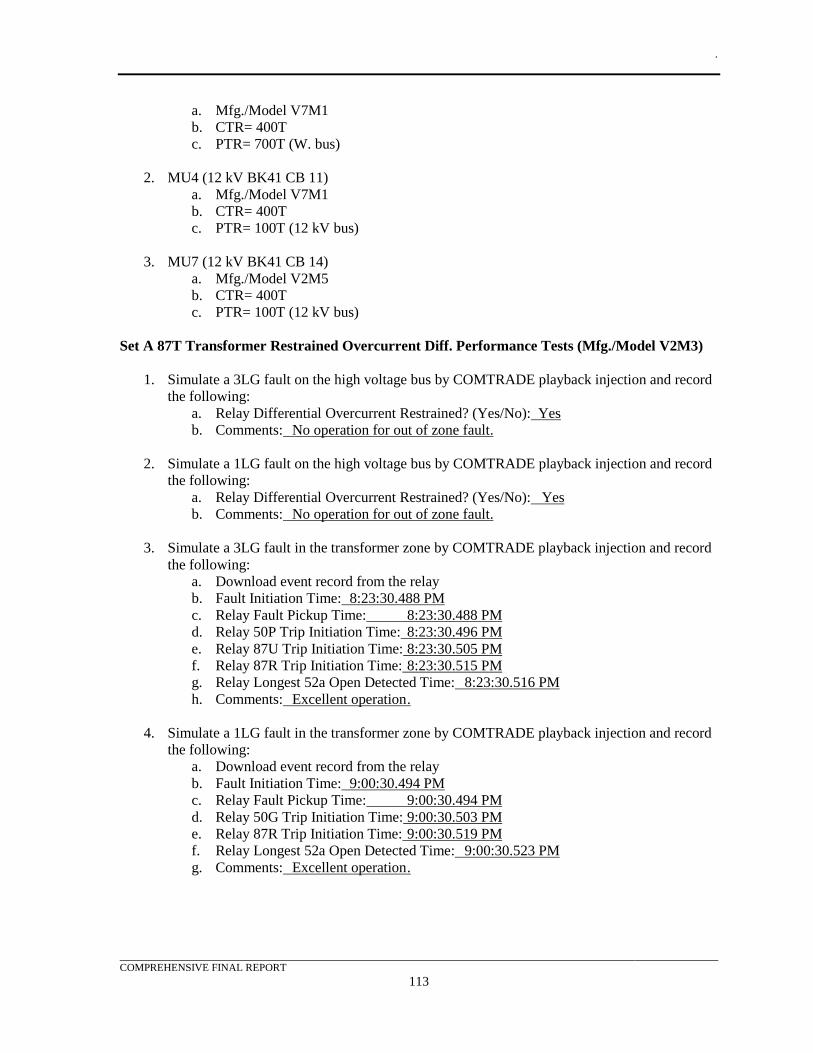
.
COMPREHENSIVE FINAL REPORT
113
a. Mfg./Model V7M1
b. CTR= 400T
c. PTR= 700T (W. bus)
2. MU4 (12 kV BK41 CB 11)
a. Mfg./Model V7M1
b. CTR= 400T
c. PTR= 100T (12 kV bus)
3. MU7 (12 kV BK41 CB 14)
a. Mfg./Model V2M5
b. CTR= 400T
c. PTR= 100T (12 kV bus)
Set A 87T Transformer Restrained Overcurrent Diff. Performance Tests (Mfg./Model V2M3)
1. Simulate a 3LG fault on the high voltage bus by COMTRADE playback injection and record
the following:
a. Relay Differential Overcurrent Restrained? (Yes/No): Yes
b. Comments: No operation for out of zone fault.
2. Simulate a 1LG fault on the high voltage bus by COMTRADE playback injection and record
the following:
a. Relay Differential Overcurrent Restrained? (Yes/No): Yes
b. Comments: No operation for out of zone fault.
3. Simulate a 3LG fault in the transformer zone by COMTRADE playback injection and record
the following:
a. Download event record from the relay
b. Fault Initiation Time: 8:23:30.488 PM
c. Relay Fault Pickup Time: 8:23:30.488 PM
d. Relay 50P Trip Initiation Time: 8:23:30.496 PM
e. Relay 87U Trip Initiation Time: 8:23:30.505 PM
f. Relay 87R Trip Initiation Time: 8:23:30.515 PM
g. Relay Longest 52a Open Detected Time: 8:23:30.516 PM
h. Comments: Excellent operation .
4. Simulate a 1LG fault in the transformer zone by COMTRADE playback injection and record
the following:
a. Download event record from the relay
b. Fault Initiation Time: 9:00:30.494 PM
c. Relay Fault Pickup Time: 9:00:30.494 PM
d. Relay 50G Trip Initiation Time: 9:00:30.503 PM
e. Relay 87R Trip Initiation Time: 9:00:30.519 PM
f. Relay Longest 52a Open Detected Time: 9:00:30.523 PM
g. Comments: Excellent operation .
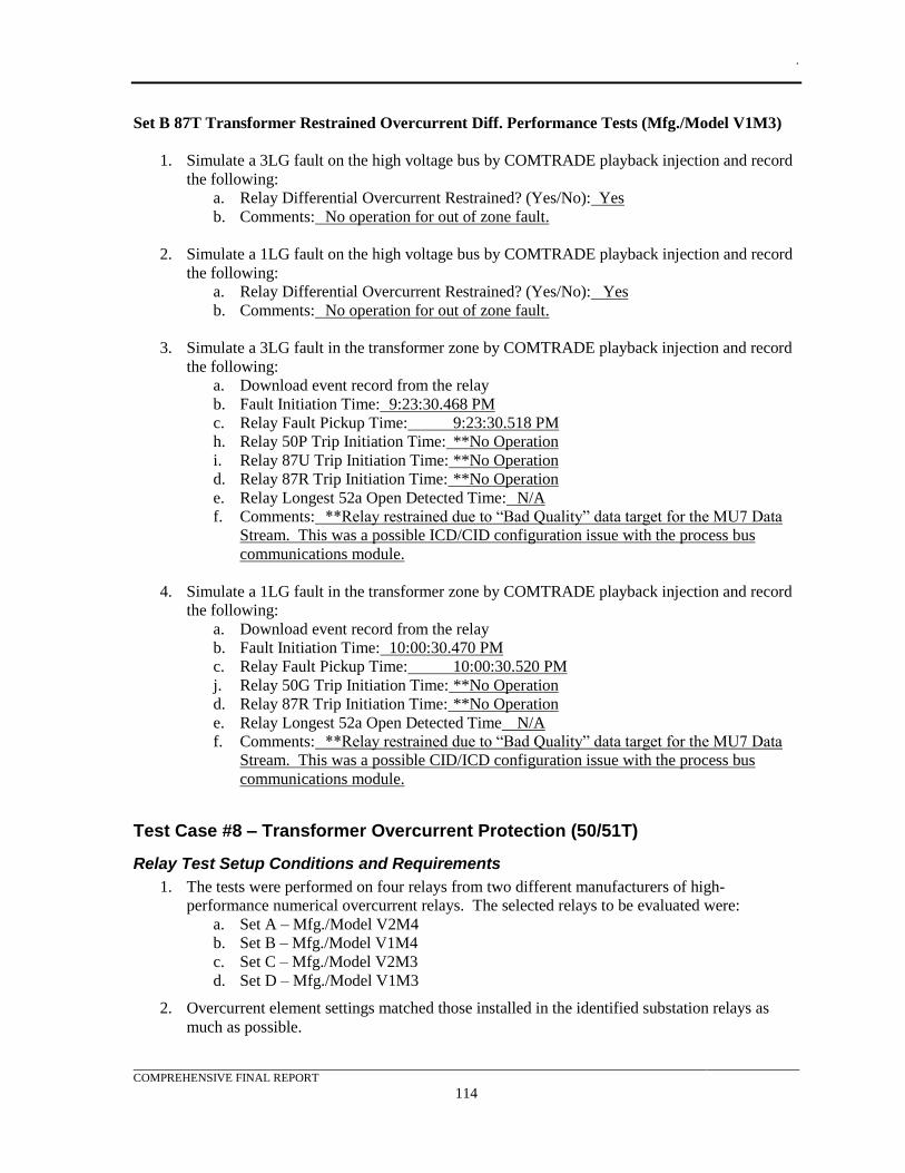
.
COMPREHENSIVE FINAL REPORT
114
Set B 87T Transformer Restrained Overcurrent Diff. Performance Tests (Mfg./Model V1M3)
1. Simulate a 3LG fault on the high voltage bus by COMTRADE playback injection and record
the following:
a. Relay Differential Overcurrent Restrained? (Yes/No): Yes
b. Comments: No operation for out of zone fault.
2. Simulate a 1LG fault on the high voltage bus by COMTRADE playback injection and record
the following:
a. Relay Differential Overcurrent Restrained? (Yes/No): Yes
b. Comments: No operation for out of zone fault.
3. Simulate a 3LG fault in the transformer zone by COMTRADE playback injection and record
the following:
a. Download event record from the relay
b. Fault Initiation Time: 9:23:30.468 PM
c. Relay Fault Pickup Time: 9:23:30.518 PM
h. Relay 50P Trip Initiation Time: **No Operation
i. Relay 87U Trip Initiation Time: **No Operation
d. Relay 87R Trip Initiation Time: **No Operation
e. Relay Longest 52a Open Detected Time: N/A
f. Comments: **Relay restrained due to “Bad Quality” data target for the MU7 Data
Stream. This was a possible ICD/CID configuration issue with the process bus
communications module.
4. Simulate a 1LG fault in the transformer zone by COMTRADE playback injection and record
the following:
a. Download event record from the relay
b. Fault Initiation Time: 10:00:30.470 PM
c. Relay Fault Pickup Time: 10:00:30.520 PM
j. Relay 50G Trip Initiation Time: **No Operation
d. Relay 87R Trip Initiation Time: **No Operation
e. Relay Longest 52a Open Detected Time N/A
f. Comments: **Relay restrained due to “Bad Quality” data target for the MU7 Data
Stream. This was a possible CID/ICD configuration issue with the process bus
communications module.
Test Case #8 – Transformer Overcurrent Protection (50/51T)
Relay Test Setup Conditions and Requirements
1. The tests were performed on four relays from two different manufacturers of high-
performance numerical overcurrent relays. The selected relays to be evaluated were:
a. Set A – Mfg./Model V2M4
b. Set B – Mfg./Model V1M4
c. Set C – Mfg./Model V2M3
d. Set D – Mfg./Model V1M3
2. Overcurrent element settings matched those installed in the identified substation relays as
much as possible.
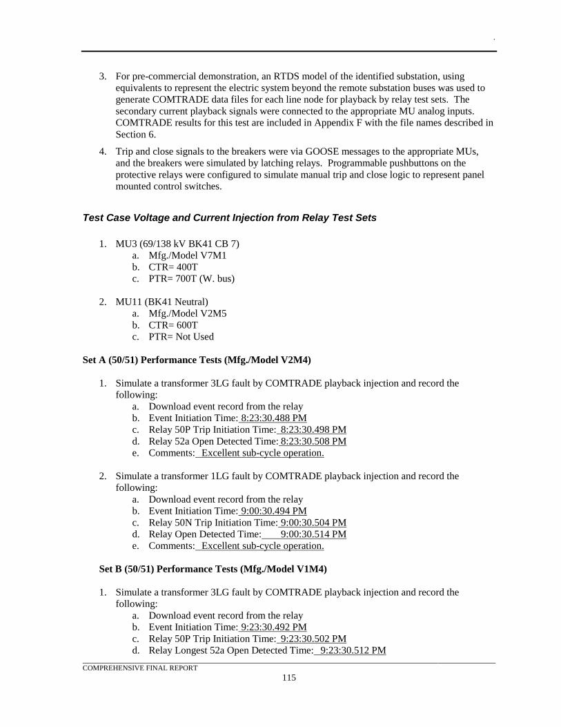
.
COMPREHENSIVE FINAL REPORT
115
3. For pre-commercial demonstration, an RTDS model of the identified substation, using
equivalents to represent the electric system beyond the remote substation buses was used to
generate COMTRADE data files for each line node for playback by relay test sets. The
secondary current playback signals were connected to the appropriate MU analog inputs.
COMTRADE results for this test are included in Appendix F with the file names described in
Section 6.
4. Trip and close signals to the breakers were via GOOSE messages to the appropriate MUs,
and the breakers were simulated by latching relays. Programmable pushbuttons on the
protective relays were configured to simulate manual trip and close logic to represent panel
mounted control switches.
Test Case Voltage and Current Injection from Relay Test Sets
1. MU3 (69/138 kV BK41 CB 7)
a. Mfg./Model V7M1
b. CTR= 400T
c. PTR= 700T (W. bus)
2. MU11 (BK41 Neutral)
a. Mfg./Model V2M5
b. CTR= 600T
c. PTR= Not Used
Set A (50/51) Performance Tests (Mfg./Model V2M4)
1. Simulate a transformer 3LG fault by COMTRADE playback injection and record the
following:
a. Download event record from the relay
b. Event Initiation Time: 8:23:30.488 PM
c. Relay 50P Trip Initiation Time: 8:23:30.498 PM
d. Relay 52a Open Detected Time: 8:23:30.508 PM
e. Comments: Excellent sub-cycle operation.
2. Simulate a transformer 1LG fault by COMTRADE playback injection and record the
following:
a. Download event record from the relay
b. Event Initiation Time: 9:00:30.494 PM
c. Relay 50N Trip Initiation Time: 9:00:30.504 PM
d. Relay Open Detected Time: 9:00:30.514 PM
e. Comments: Excellent sub-cycle operation.
Set B (50/51) Performance Tests (Mfg./Model V1M4)
1. Simulate a transformer 3LG fault by COMTRADE playback injection and record the
following:
a. Download event record from the relay
b. Event Initiation Time: 9:23:30.492 PM
c. Relay 50P Trip Initiation Time: 9:23:30.502 PM
d. Relay Longest 52a Open Detected Time: 9:23:30.512 PM
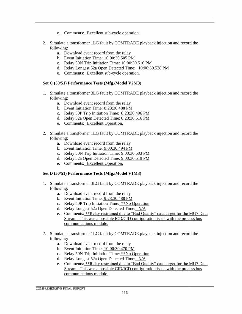
.
COMPREHENSIVE FINAL REPORT
116
e. Comments: Excellent sub-cycle operation.
2. Simulate a transformer 1LG fault by COMTRADE playback injection and record the
following:
a. Download event record from the relay
b. Event Initiation Time: 10:00:30.505 PM
c. Relay 50N Trip Initiation Time: 10:00:30.516 PM
d. Relay Longest 52a Open Detected Time: 10:00:30.528 PM
e. Comments: Excellent sub-cycle operation.
Set C (50/51) Performance Tests (Mfg./Model V2M3)
1. Simulate a transformer 3LG fault by COMTRADE playback injection and record the
following:
a. Download event record from the relay
b. Event Initiation Time: 8:23:30.488 PM
c. Relay 50P Trip Initiation Time: 8:23:30.496 PM
d. Relay 52a Open Detected Time: 8:23:30.516 PM
e. Comments: Excellent Operation.
2. Simulate a transformer 1LG fault by COMTRADE playback injection and record the
following:
a. Download event record from the relay
b. Event Initiation Time: 9:00:30.494 PM
c. Relay 50N Trip Initiation Time: 9:00:30.503 PM
d. Relay 52a Open Detected Time: 9:00:30.519 PM
e. Comments: Excellent Operation.
Set D (50/51) Performance Tests (Mfg./Model V1M3)
1. Simulate a transformer 3LG fault by COMTRADE playback injection and record the
following:
a. Download event record from the relay
b. Event Initiation Time: 9:23:30.488 PM
c. Relay 50P Trip Initiation Time: **No Operation
d. Relay Longest 52a Open Detected Time: N/A
e. Comments: **Relay restrained due to “Bad Quality” data target for the MU7 Data
Stream. This was a possible ICD/CID configuration issue with the process bus
communications module.
2. Simulate a transformer 1LG fault by COMTRADE playback injection and record the
following:
a. Download event record from the relay
b. Event Initiation Time: 10:00:30.470 PM
c. Relay 50N Trip Initiation Time: **No Operation
d. Relay Longest 52a Open Detected Time: N/A
e. Comments: **Relay restrained due to “Bad Quality” data target for the MU7 Data
Stream. This was a possible CID/ICD configuration issue with the process bus
communications module.
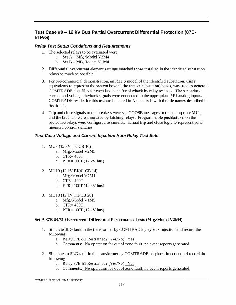
.
COMPREHENSIVE FINAL REPORT
117
Test Case #9 – 12 kV Bus Partial Overcurrent Differential Protection (87B-51P/G)
Relay Test Setup Conditions and Requirements
1. The selected relays to be evaluated were:
a. Set A – Mfg./Model V2M4
b. Set B – Mfg./Model V1M4
2. Differential overcurrent element settings matched those installed in the identified substation
relays as much as possible.
3. For pre-commercial demonstration, an RTDS model of the identified substation, using
equivalents to represent the system beyond the remote substation) buses, was used to generate
COMTRADE data files for each line node for playback by relay test sets. The secondary
current and voltage playback signals were connected to the appropriate MU analog inputs.
COMTRADE results for this test are included in Appendix F with the file names described in
Section 6.
4. Trip and close signals to the breakers were via GOOSE messages to the appropriate MUs,
and the breakers were simulated by latching relays. Programmable pushbuttons on the
protective relays were configured to simulate manual trip and close logic to represent panel
mounted control switches.
Test Case Voltage and Current Injection from Relay Test Sets
1. MU5 (12 kV Tie CB 10)
a. Mfg./Model V2M5
b. CTR= 400T
c. PTR= 100T (12 kV bus)
2. MU10 (12 kV BK41 CB 14)
a. Mfg./Model V7M1
b. CTR= 400T
c. PTR= 100T (12 kV bus)
3. MU13 (12 kV Tie CB 20)
a. Mfg./Model V1M5
b. CTR= 400T
c. PTR= 100T (12 kV bus)
Set A 87B-50/51 Overcurrent Differential Performance Tests (Mfg./Model V2M4)
1. Simulate 3LG fault in the transformer by COMTRADE playback injection and record the
following:
a. Relay 87B-51 Restrained? (Yes/No): Yes
b. Comments: No operation for out of zone fault, no event reports generated.
2. Simulate an SLG fault in the transformer by COMTRADE playback injection and record the
following:
a. Relay 87B-51 Restrained? (Yes/No): Yes
b. Comments: No operation for out of zone fault, no event reports generated.
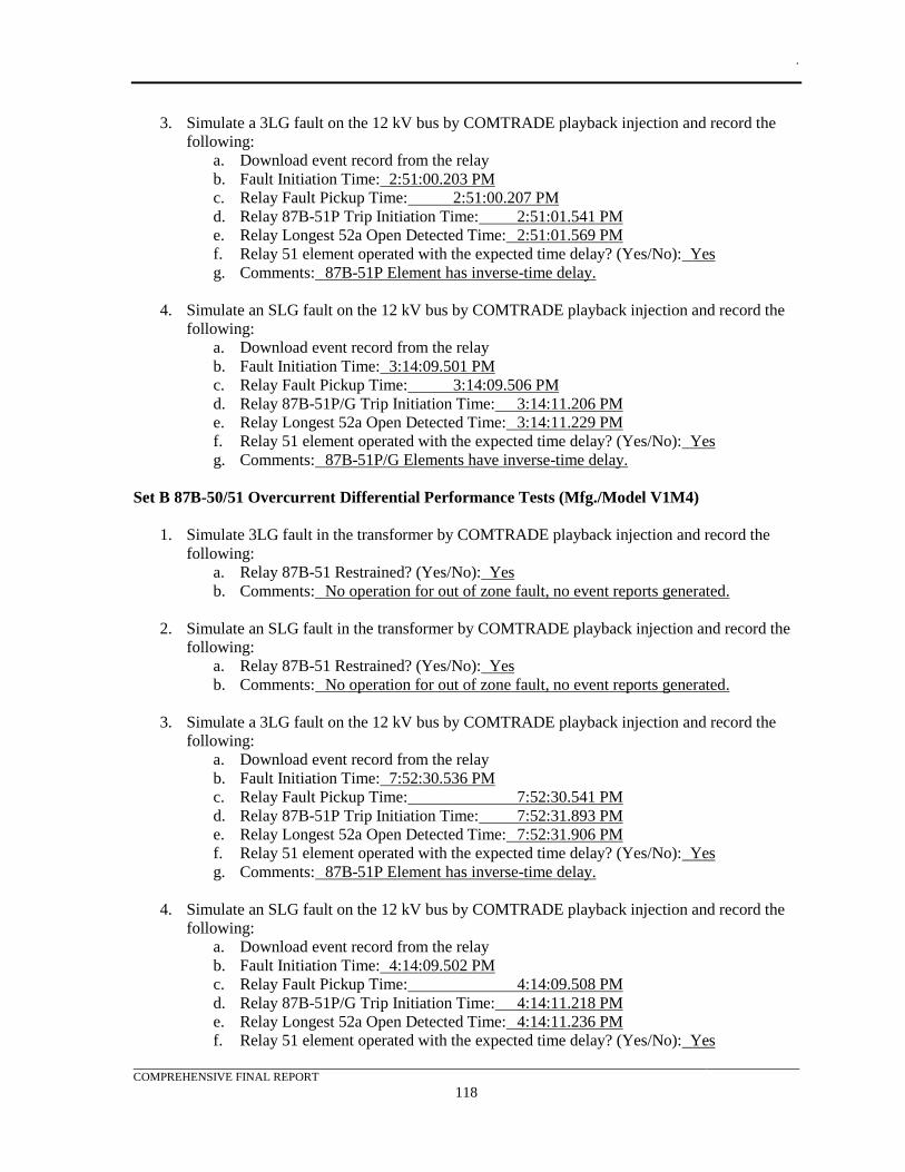
.
COMPREHENSIVE FINAL REPORT
118
3. Simulate a 3LG fault on the 12 kV bus by COMTRADE playback injection and record the
following:
a. Download event record from the relay
b. Fault Initiation Time: 2:51:00.203 PM
c. Relay Fault Pickup Time: 2:51:00.207 PM
d. Relay 87B-51P Trip Initiation Time: 2:51:01.541 PM
e. Relay Longest 52a Open Detected Time: 2:51:01.569 PM
f. Relay 51 element operated with the expected time delay? (Yes/No): Yes
g. Comments: 87B-51P Element has inverse-time delay.
4. Simulate an SLG fault on the 12 kV bus by COMTRADE playback injection and record the
following:
a. Download event record from the relay
b. Fault Initiation Time: 3:14:09.501 PM
c. Relay Fault Pickup Time: 3:14:09.506 PM
d. Relay 87B-51P/G Trip Initiation Time: 3:14:11.206 PM
e. Relay Longest 52a Open Detected Time: 3:14:11.229 PM
f. Relay 51 element operated with the expected time delay? (Yes/No): Yes
g. Comments: 87B-51P/G Elements have inverse-time delay.
Set B 87B-50/51 Overcurrent Differential Performance Tests (Mfg./Model V1M4)
1. Simulate 3LG fault in the transformer by COMTRADE playback injection and record the
following:
a. Relay 87B-51 Restrained? (Yes/No): Yes
b. Comments: No operation for out of zone fault, no event reports generated.
2. Simulate an SLG fault in the transformer by COMTRADE playback injection and record the
following:
a. Relay 87B-51 Restrained? (Yes/No): Yes
b. Comments: No operation for out of zone fault, no event reports generated.
3. Simulate a 3LG fault on the 12 kV bus by COMTRADE playback injection and record the
following:
a. Download event record from the relay
b. Fault Initiation Time: 7:52:30.536 PM
c. Relay Fault Pickup Time: 7:52:30.541 PM
d. Relay 87B-51P Trip Initiation Time: 7:52:31.893 PM
e. Relay Longest 52a Open Detected Time: 7:52:31.906 PM
f. Relay 51 element operated with the expected time delay? (Yes/No): Yes
g. Comments: 87B-51P Element has inverse-time delay.
4. Simulate an SLG fault on the 12 kV bus by COMTRADE playback injection and record the
following:
a. Download event record from the relay
b. Fault Initiation Time: 4:14:09.502 PM
c. Relay Fault Pickup Time: 4:14:09.508 PM
d. Relay 87B-51P/G Trip Initiation Time: 4:14:11.218 PM
e. Relay Longest 52a Open Detected Time: 4:14:11.236 PM
f. Relay 51 element operated with the expected time delay? (Yes/No): Yes
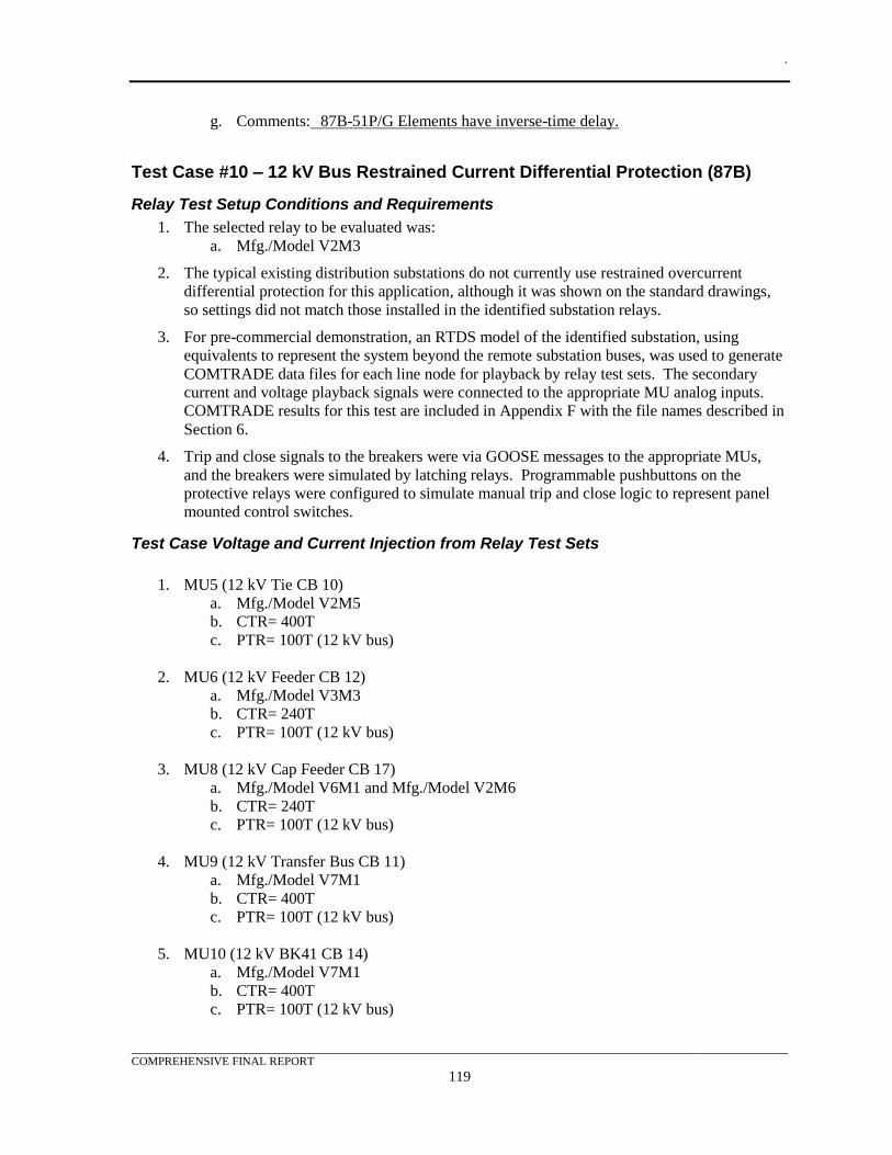
.
COMPREHENSIVE FINAL REPORT
119
g. Comments: 87B-51P/G Elements have inverse-time delay.
Test Case #10 – 12 kV Bus Restrained Current Differential Protection (87B)
Relay Test Setup Conditions and Requirements
1. The selected relay to be evaluated was:
a. Mfg./Model V2M3
2. The typical existing distribution substations do not currently use restrained overcurrent
differential protection for this application, although it was shown on the standard drawings,
so settings did not match those installed in the identified substation relays.
3. For pre-commercial demonstration, an RTDS model of the identified substation, using
equivalents to represent the system beyond the remote substation buses, was used to generate
COMTRADE data files for each line node for playback by relay test sets. The secondary
current and voltage playback signals were connected to the appropriate MU analog inputs.
COMTRADE results for this test are included in Appendix F with the file names described in
Section 6.
4. Trip and close signals to the breakers were via GOOSE messages to the appropriate MUs,
and the breakers were simulated by latching relays. Programmable pushbuttons on the
protective relays were configured to simulate manual trip and close logic to represent panel
mounted control switches.
Test Case Voltage and Current Injection from Relay Test Sets
1. MU5 (12 kV Tie CB 10)
a. Mfg./Model V2M5
b. CTR= 400T
c. PTR= 100T (12 kV bus)
2. MU6 (12 kV Feeder CB 12)
a. Mfg./Model V3M3
b. CTR= 240T
c. PTR= 100T (12 kV bus)
3. MU8 (12 kV Cap Feeder CB 17)
a. Mfg./Model V6M1 and Mfg./Model V2M6
b. CTR= 240T
c. PTR= 100T (12 kV bus)
4. MU9 (12 kV Transfer Bus CB 11)
a. Mfg./Model V7M1
b. CTR= 400T
c. PTR= 100T (12 kV bus)
5. MU10 (12 kV BK41 CB 14)
a. Mfg./Model V7M1
b. CTR= 400T
c. PTR= 100T (12 kV bus)
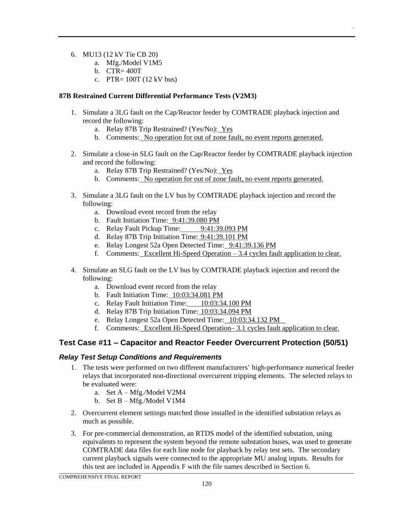
.
COMPREHENSIVE FINAL REPORT
120
6. MU13 (12 kV Tie CB 20)
a. Mfg./Model V1M5
b. CTR= 400T
c. PTR= 100T (12 kV bus)
87B Restrained Current Differential Performance Tests (V2M3)
1. Simulate a 3LG fault on the Cap/Reactor feeder by COMTRADE playback injection and
record the following:
a. Relay 87B Trip Restrained? (Yes/No): Yes
b. Comments: No operation for out of zone fault, no event reports generated.
2. Simulate a close-in SLG fault on the Cap/Reactor feeder by COMTRADE playback injection
and record the following:
a. Relay 87B Trip Restrained? (Yes/No): Yes
b. Comments: No operation for out of zone fault, no event reports generated.
3. Simulate a 3LG fault on the LV bus by COMTRADE playback injection and record the
following:
a. Download event record from the relay
b. Fault Initiation Time: 9:41:39.080 PM
c. Relay Fault Pickup Time: 9:41:39.093 PM
d. Relay 87B Trip Initiation Time: 9:41:39.101 PM
e. Relay Longest 52a Open Detected Time: 9:41:39.136 PM
f. Comments: Excellent Hi-Speed Operation – 3.4 cycles fault application to clear.
4. Simulate an SLG fault on the LV bus by COMTRADE playback injection and record the
following:
a. Download event record from the relay
b. Fault Initiation Time: 10:03:34.081 PM
c. Relay Fault Initiation Time: 10:03:34.100 PM
d. Relay 87B Trip Initiation Time: 10:03:34.094 PM
e. Relay Longest 52a Open Detected Time: 10:03:34.132 PM
f. Comments: Excellent Hi-Speed Operation– 3.1 cycles fault application to clear.
Test Case #11 – Capacitor and Reactor Feeder Overcurrent Protection (50/51)
Relay Test Setup Conditions and Requirements
1. The tests were performed on two different manufacturers’ high-performance numerical feeder
relays that incorporated non-directional overcurrent tripping elements. The selected relays to
be evaluated were:
a. Set A – Mfg./Model V2M4
b. Set B – Mfg./Model V1M4
2. Overcurrent element settings matched those installed in the identified substation relays as
much as possible.
3. For pre-commercial demonstration, an RTDS model of the identified substation, using
equivalents to represent the system beyond the remote substation buses, was used to generate
COMTRADE data files for each line node for playback by relay test sets. The secondary
current playback signals were connected to the appropriate MU analog inputs. Results for
this test are included in Appendix F with the file names described in Section 6.
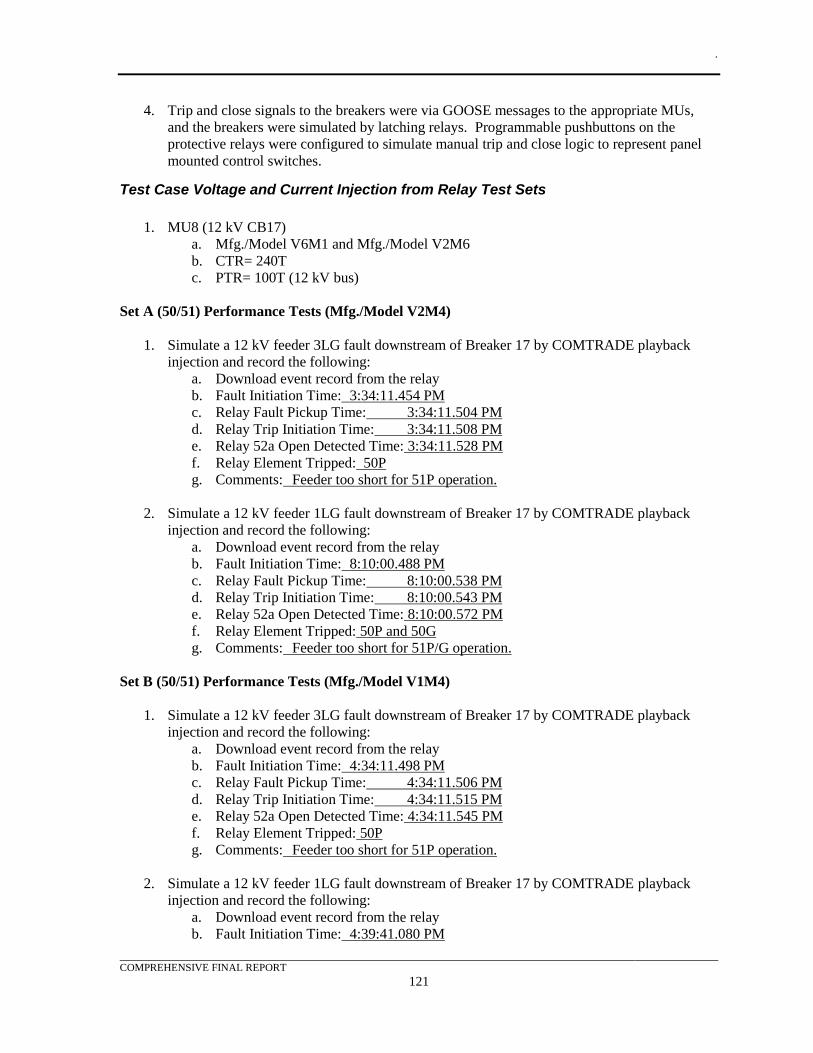
.
COMPREHENSIVE FINAL REPORT
121
4. Trip and close signals to the breakers were via GOOSE messages to the appropriate MUs,
and the breakers were simulated by latching relays. Programmable pushbuttons on the
protective relays were configured to simulate manual trip and close logic to represent panel
mounted control switches.
Test Case Voltage and Current Injection from Relay Test Sets
1. MU8 (12 kV CB17)
a. Mfg./Model V6M1 and Mfg./Model V2M6
b. CTR= 240T
c. PTR= 100T (12 kV bus)
Set A (50/51) Performance Tests (Mfg./Model V2M4)
1. Simulate a 12 kV feeder 3LG fault downstream of Breaker 17 by COMTRADE playback
injection and record the following:
a. Download event record from the relay
b. Fault Initiation Time: 3:34:11.454 PM
c. Relay Fault Pickup Time: 3:34:11.504 PM
d. Relay Trip Initiation Time: 3:34:11.508 PM
e. Relay 52a Open Detected Time: 3:34:11.528 PM
f. Relay Element Tripped: 50P
g. Comments: Feeder too short for 51P operation.
2. Simulate a 12 kV feeder 1LG fault downstream of Breaker 17 by COMTRADE playback
injection and record the following:
a. Download event record from the relay
b. Fault Initiation Time: 8:10:00.488 PM
c. Relay Fault Pickup Time: 8:10:00.538 PM
d. Relay Trip Initiation Time: 8:10:00.543 PM
e. Relay 52a Open Detected Time: 8:10:00.572 PM
f. Relay Element Tripped: 50P and 50G
g. Comments: Feeder too short for 51P/G operation.
Set B (50/51) Performance Tests (Mfg./Model V1M4)
1. Simulate a 12 kV feeder 3LG fault downstream of Breaker 17 by COMTRADE playback
injection and record the following:
a. Download event record from the relay
b. Fault Initiation Time: 4:34:11.498 PM
c. Relay Fault Pickup Time: 4:34:11.506 PM
d. Relay Trip Initiation Time: 4:34:11.515 PM
e. Relay 52a Open Detected Time: 4:34:11.545 PM
f. Relay Element Tripped: 50P
g. Comments: Feeder too short for 51P operation.
2. Simulate a 12 kV feeder 1LG fault downstream of Breaker 17 by COMTRADE playback
injection and record the following:
a. Download event record from the relay
b. Fault Initiation Time: 4:39:41.080 PM
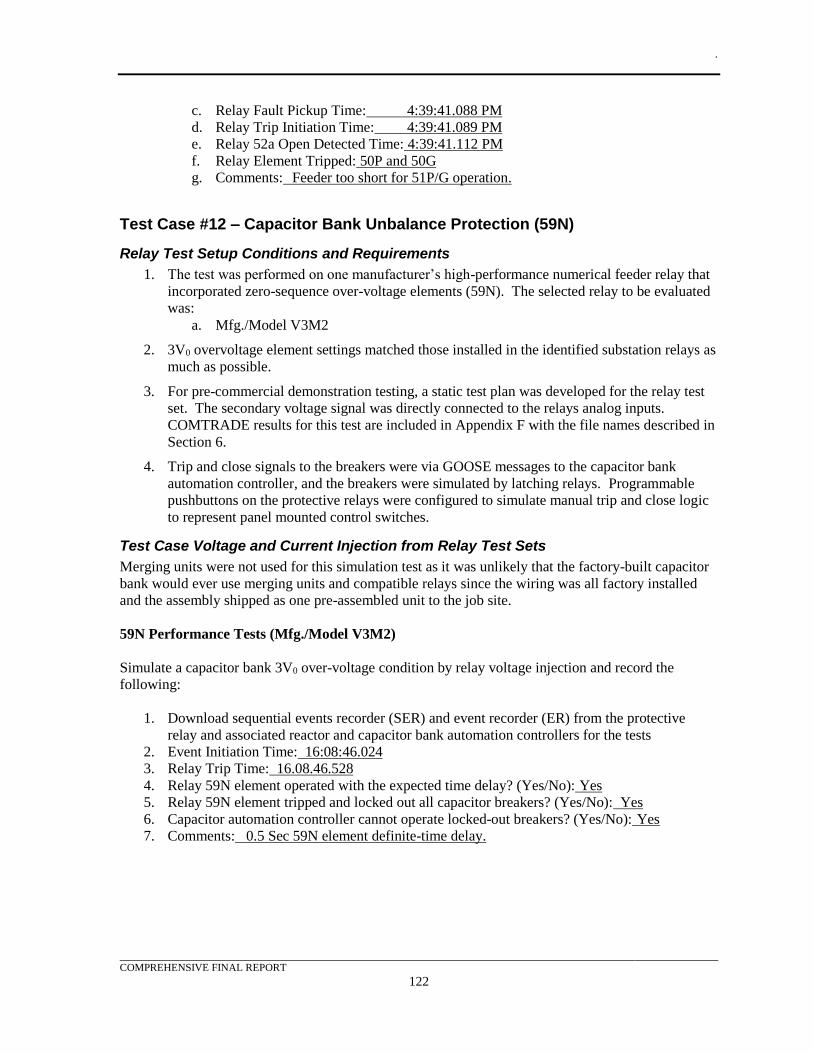
.
COMPREHENSIVE FINAL REPORT
122
c. Relay Fault Pickup Time: 4:39:41.088 PM
d. Relay Trip Initiation Time: 4:39:41.089 PM
e. Relay 52a Open Detected Time: 4:39:41.112 PM
f. Relay Element Tripped: 50P and 50G
g. Comments: Feeder too short for 51P/G operation.
Test Case #12 – Capacitor Bank Unbalance Protection (59N)
Relay Test Setup Conditions and Requirements
1. The test was performed on one manufacturer’s high-performance numerical feeder relay that
incorporated zero-sequence over-voltage elements (59N). The selected relay to be evaluated
was:
a. Mfg./Model V3M2
2. 3V0 overvoltage element settings matched those installed in the identified substation relays as
much as possible.
3. For pre-commercial demonstration testing, a static test plan was developed for the relay test
set. The secondary voltage signal was directly connected to the relays analog inputs.
COMTRADE results for this test are included in Appendix F with the file names described in
Section 6.
4. Trip and close signals to the breakers were via GOOSE messages to the capacitor bank
automation controller, and the breakers were simulated by latching relays. Programmable
pushbuttons on the protective relays were configured to simulate manual trip and close logic
to represent panel mounted control switches.
Test Case Voltage and Current Injection from Relay Test Sets
Merging units were not used for this simulation test as it was unlikely that the factory-built capacitor
bank would ever use merging units and compatible relays since the wiring was all factory installed
and the assembly shipped as one pre-assembled unit to the job site.
59N Performance Tests (Mfg./Model V3M2)
Simulate a capacitor bank 3V0 over-voltage condition by relay voltage injection and record the
following:
1. Download sequential events recorder (SER) and event recorder (ER) from the protective
relay and associated reactor and capacitor bank automation controllers for the tests
2. Event Initiation Time: 16:08:46.024
3. Relay Trip Time: 16.08.46.528
4. Relay 59N element operated with the expected time delay? (Yes/No): Yes
5. Relay 59N element tripped and locked out all capacitor breakers? (Yes/No): Yes
6. Capacitor automation controller cannot operate locked-out breakers? (Yes/No): Yes
7. Comments: 0.5 Sec 59N element definite-time delay.
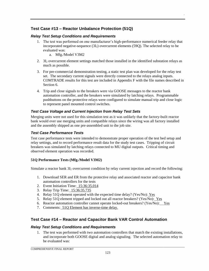
.
COMPREHENSIVE FINAL REPORT
123
Test Case #13 – Reactor Unbalance Protection (51Q)
Relay Test Setup Conditions and Requirements
1. The test was performed on one manufacturer’s high-performance numerical feeder relay that
incorporated negative-sequence (3I2) overcurrent elements (59Q). The selected relay to be
evaluated was:
a. Mfg./Model V3M2
2. 3I2 overcurrent element settings matched those installed in the identified substation relays as
much as possible.
3. For pre-commercial demonstration testing, a static test plan was developed for the relay test
set. The secondary current signals were directly connected to the relays analog inputs.
COMTRADE results for this test are included in Appendix F with the file names described in
Section 6.
4. Trip and close signals to the breakers were via GOOSE messages to the reactor bank
automation controller, and the breakers were simulated by latching relays. Programmable
pushbuttons on the protective relays were configured to simulate manual trip and close logic
to represent panel mounted control switches.
Test Case Voltage and Current Injection from Relay Test Sets
Merging units were not used for this simulation test as it was unlikely that the factory-built reactor
bank would ever use merging units and compatible relays since the wiring was all factory installed
and the assembly shipped as one pre-assembled unit to the job site.
Test Case Performance Tests
Test case performance tests were intended to demonstrate proper operation of the test bed setup and
relay settings, and to record performance result data for the study test cases. Tripping of circuit
breakers was simulated by latching relays connected to MU digital outputs. Critical timing and
observed element operation was recorded.
51Q Performance Tests (Mfg./Model V3M2)
Simulate a reactor bank 3I2 overcurrent condition by relay current injection and record the following:
1. Download SER and ER from the protective relay and associated reactor and capacitor bank
automation controllers for the tests
2. Event Initiation Time: 15:36:35.014
3. Relay Trip Time: 15:36:35.735
4. Relay 51Q element operated with the expected time delay? (Yes/No): Yes
5. Relay 51Q element tripped and locked out all reactor breakers? (Yes/No): Yes
6. Reactor automation controller cannot operate locked-out breakers? (Yes/No): Yes
7. Comments: 51Q Element has inverse-time delay.
Test Case #14 – Reactor and Capacitor Bank VAR Control Automation
Relay Test Setup Conditions and Requirements
1. The test was performed with two automation controllers that match the existing installations,
and incorporate both GOOSE digital and analog signaling. The selected automation relay to
be evaluated was:
.
COMPREHENSIVE FINAL REPORT
124
a. Mfg./Model V3M4
2. The test was performed using one manufacturer’s high-performance numerical overcurrent
relay to measure and signal VAR flow data via GOOSE analogs. This relay was used to line
impedance and overcurrent protection (see Line Distance and Directional Overcurrent Test
Case above), but was mapped to MU3 which was transformer primary breaker CB7. The
selected relay to be used was:
a. Mfg./Model V3M1
3. Automation controller logic settings matched those installed in the most recent capacitor and
reactor bank installations as much as possible.
4. For pre-commercial demonstration testing, a static test plan was developed for the relay test
set because RTDS simulation files would be too large for the relay test sets for what was a
slow operating control function (switching in/out reactors and capacitors would never be
performed quickly in regulatory control applications to avoid voltage instability and excess
wear on the breakers). The secondary current and voltage simulation signals from the test set
were connected to the appropriate MU analog inputs. SER results for this test are included in
Appendix F with the file names described in Section 6.
5. Trip and close signals to the breakers were via GOOSE messages to the reactor bank
automation controller, and the breakers were simulated by latching relays. Programmable
pushbuttons and targets on the protective relays and automation controllers were configured
to simulate manual trip and close logic to represent panel mounted control switches and panel
status lamps for the breakers.
Test Case Voltage and Current Injection from Relay Test Sets
1. MU3 (69/138 kV BK41 CB 7)
a. Mfg./Model V7M1
b. CTR= 400T
c. PTR= 700T (W. bus)
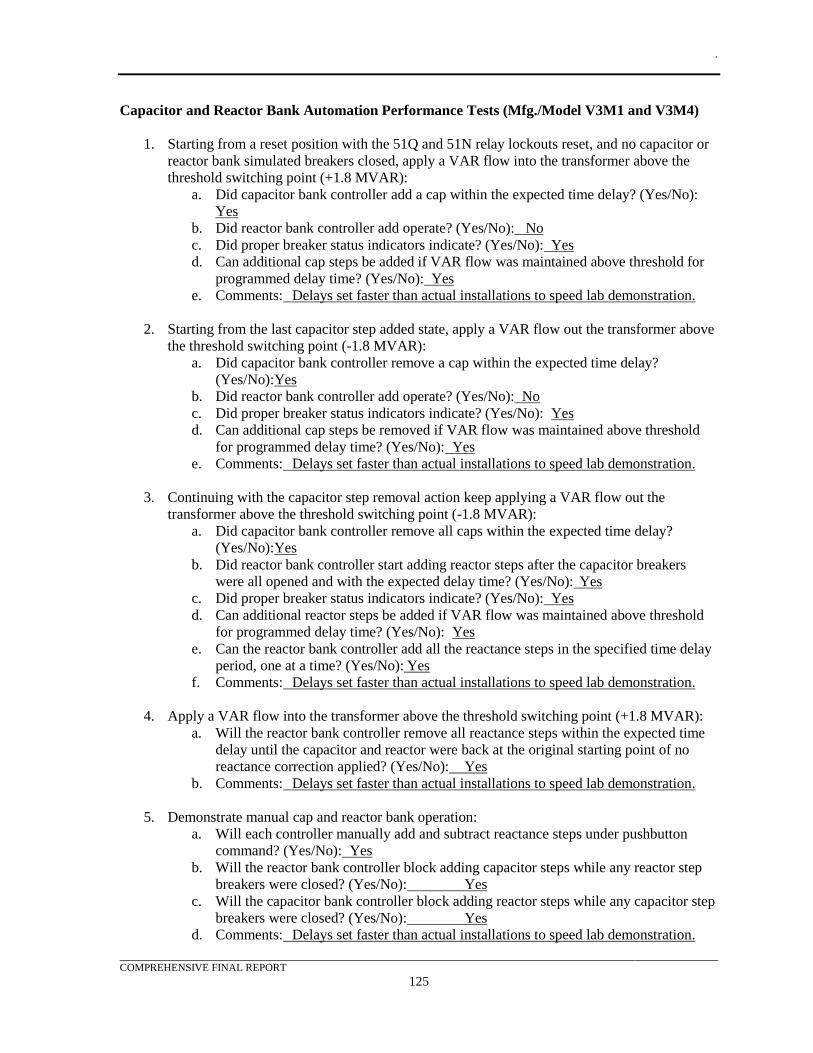
.
COMPREHENSIVE FINAL REPORT
125
Capacitor and Reactor Bank Automation Performance Tests (Mfg./Model V3M1 and V3M4)
1. Starting from a reset position with the 51Q and 51N relay lockouts reset, and no capacitor or
reactor bank simulated breakers closed, apply a VAR flow into the transformer above the
threshold switching point (+1.8 MVAR):
a. Did capacitor bank controller add a cap within the expected time delay? (Yes/No):
Yes
b. Did reactor bank controller add operate? (Yes/No): No
c. Did proper breaker status indicators indicate? (Yes/No): Yes
d. Can additional cap steps be added if VAR flow was maintained above threshold for
programmed delay time? (Yes/No): Yes
e. Comments: Delays set faster than actual installations to speed lab demonstration.
2. Starting from the last capacitor step added state, apply a VAR flow out the transformer above
the threshold switching point (-1.8 MVAR):
a. Did capacitor bank controller remove a cap within the expected time delay?
(Yes/No):Yes
b. Did reactor bank controller add operate? (Yes/No): No
c. Did proper breaker status indicators indicate? (Yes/No): Yes
d. Can additional cap steps be removed if VAR flow was maintained above threshold
for programmed delay time? (Yes/No): Yes
e. Comments: Delays set faster than actual installations to speed lab demonstration.
3. Continuing with the capacitor step removal action keep applying a VAR flow out the
transformer above the threshold switching point (-1.8 MVAR):
a. Did capacitor bank controller remove all caps within the expected time delay?
(Yes/No):Yes
b. Did reactor bank controller start adding reactor steps after the capacitor breakers
were all opened and with the expected delay time? (Yes/No): Yes
c. Did proper breaker status indicators indicate? (Yes/No): Yes
d. Can additional reactor steps be added if VAR flow was maintained above threshold
for programmed delay time? (Yes/No): Yes
e. Can the reactor bank controller add all the reactance steps in the specified time delay
period, one at a time? (Yes/No): Yes
f. Comments: Delays set faster than actual installations to speed lab demonstration.
4. Apply a VAR flow into the transformer above the threshold switching point (+1.8 MVAR):
a. Will the reactor bank controller remove all reactance steps within the expected time
delay until the capacitor and reactor were back at the original starting point of no
reactance correction applied? (Yes/No): Yes
b. Comments: Delays set faster than actual installations to speed lab demonstration.
5. Demonstrate manual cap and reactor bank operation:
a. Will each controller manually add and subtract reactance steps under pushbutton
command? (Yes/No): Yes
b. Will the reactor bank controller block adding capacitor steps while any reactor step
breakers were closed? (Yes/No): Yes
c. Will the capacitor bank controller block adding reactor steps while any capacitor step
breakers were closed? (Yes/No): Yes
d. Comments: Delays set faster than actual installations to speed lab demonstration.
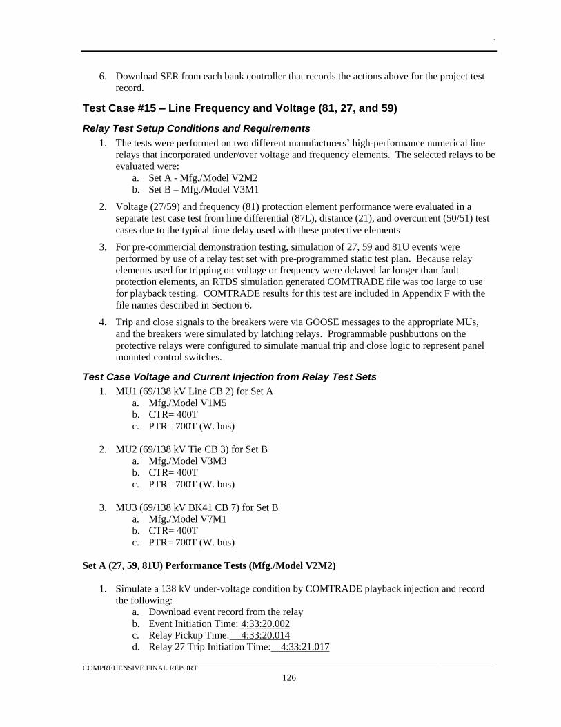
.
COMPREHENSIVE FINAL REPORT
126
6. Download SER from each bank controller that records the actions above for the project test
record.
Test Case #15 – Line Frequency and Voltage (81, 27, and 59)
Relay Test Setup Conditions and Requirements
1. The tests were performed on two different manufacturers’ high-performance numerical line
relays that incorporated under/over voltage and frequency elements. The selected relays to be
evaluated were:
a. Set A - Mfg./Model V2M2
b. Set B – Mfg./Model V3M1
2. Voltage (27/59) and frequency (81) protection element performance were evaluated in a
separate test case test from line differential (87L), distance (21), and overcurrent (50/51) test
cases due to the typical time delay used with these protective elements
3. For pre-commercial demonstration testing, simulation of 27, 59 and 81U events were
performed by use of a relay test set with pre-programmed static test plan. Because relay
elements used for tripping on voltage or frequency were delayed far longer than fault
protection elements, an RTDS simulation generated COMTRADE file was too large to use
for playback testing. COMTRADE results for this test are included in Appendix F with the
file names described in Section 6.
4. Trip and close signals to the breakers were via GOOSE messages to the appropriate MUs,
and the breakers were simulated by latching relays. Programmable pushbuttons on the
protective relays were configured to simulate manual trip and close logic to represent panel
mounted control switches.
Test Case Voltage and Current Injection from Relay Test Sets
1. MU1 (69/138 kV Line CB 2) for Set A
a. Mfg./Model V1M5
b. CTR= 400T
c. PTR= 700T (W. bus)
2. MU2 (69/138 kV Tie CB 3) for Set B
a. Mfg./Model V3M3
b. CTR= 400T
c. PTR= 700T (W. bus)
3. MU3 (69/138 kV BK41 CB 7) for Set B
a. Mfg./Model V7M1
b. CTR= 400T
c. PTR= 700T (W. bus)
Set A (27, 59, 81U) Performance Tests (Mfg./Model V2M2)
1. Simulate a 138 kV under-voltage condition by COMTRADE playback injection and record
the following:
a. Download event record from the relay
b. Event Initiation Time: 4:33:20.002
c. Relay Pickup Time: 4:33:20.014
d. Relay 27 Trip Initiation Time: 4:33:21.017
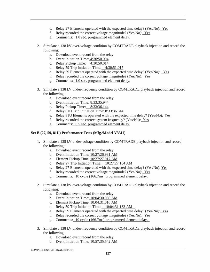
.
COMPREHENSIVE FINAL REPORT
127
e. Relay 27 Elements operated with the expected time delay? (Yes/No): Yes
f. Relay recorded the correct voltage magnitude? (Yes/No): Yes
g. Comments: 1.0 sec. programmed element delay.
2. Simulate a 138 kV over-voltage condition by COMTRADE playback injection and record the
following:
a. Download event record from the relay
b. Event Initiation Time: 4:30:50.994
c. Relay Pickup Time: 4:30:50.014
d. Relay 59 Trip Initiation Time: 4:30:51.017
e. Relay 59 Elements operated with the expected time delay? (Yes/No): Yes
f. Relay recorded the correct voltage magnitude? (Yes/No): Yes
g. Comments: 1.0 sec. programmed element delay.
3. Simulate a 138 kV under-frequency condition by COMTRADE playback injection and record
the following:
a. Download event record from the relay
b. Event Initiation Time: 8:33:35.944
c. Relay Pickup Time: 8:33:36.144
d. Relay 81U Trip Initiation Time: 8:33:36.644
e. Relay 81U Elements operated with the expected time delay? (Yes/No): Yes
f. Relay recorded the correct system frequency? (Yes/No): Yes
g. Comments: 0.5 sec. programmed element delay.
Set B (27, 59, 81U) Performance Tests (Mfg./Model V3M1)
1. Simulate a 138 kV under-voltage condition by COMTRADE playback injection and record
the following:
a. Download event record from the relay
b. Event Initiation Time: 10:27:26.981 AM
c. Element Pickup Time: 10:27:27.017 AM
d. Relay 27 Trip Initiation Time: 10:27:27.184 AM
e. Relay 27 Elements operated with the expected time delay? (Yes/No): Yes
f. Relay recorded the correct voltage magnitude? (Yes/No): Yes
g. Comments: 10 cycle (166.7ms) programmed element delay.
2. Simulate a 138 kV over-voltage condition by COMTRADE playback injection and record the
following:
a. Download event record from the relay
b. Event Initiation Time: 10:04:30.980 AM
c. Element Pickup Time: 10:04:31.016 AM
d. Relay 59 Trip Initiation Time: 10:04:31.183 AM
e. Relay 59 Elements operated with the expected time delay? (Yes/No): Yes
f. Relay recorded the correct voltage magnitude? (Yes/No): Yes
g. Comments: 10 cycle (166.7ms) programmed element delay.
3. Simulate a 138 kV under-frequency condition by COMTRADE playback injection and record
the following:
a. Download event record from the relay
b. Event Initiation Time: 10:57:35.542 AM
.
COMPREHENSIVE FINAL REPORT
128
c. Element Pickup Time: 10:57:35.559 AM
d. Relay 81U Trip Initiation Time: 10:57:36.059 AM
e. Relay 81U Elements operated with the expected time delay? (Yes/No): Yes
f. Relay recorded the correct system frequency? (Yes/No): Yes
g. Comments: 0.5 sec. programmed element delay.
.
COMPREHENSIVE FINAL REPORT
129
11. TEST RESULTS AND DATA ANALYSIS The analysis of test results and data and the methodology for the development of findings are
discussed below. After the testing was completed, each of the items identified in the test plan were
reviewed and assigned to an engineer for analysis.
Measurement and Verification
The project team provided metrics for the performance of their traditional hardwired protective relay
system. The primary measurement of interest was the protection system operation time. This time
was measured from the initiation of the fault condition until the relay received status that the breaker
simulator had operated. These values were used to compare the performance of the IEC 61850
protection and control schemes, identified in the use cases, to the traditional P&C schemes. This
information was readily obtained from the relay event recorders and COMTRADE waveform capture
capabilities in the relays. See Appendix F for COMTRADE graphical analysis.
Interoperability was more subjective. In general, the interoperability requirements were met if any
two devices could communicate via GOOSE and SV. The fact that the test system was able to
simulate all the use cases was evidence that interoperability was achieved.
Impacts on Existing Substation and Transmission Protection
The main protection concerns that were identified in this project were speed and reliability. The
following items address these concerns.
Reliability – Protection
Protection with IEC 61850 SV performs no differently than a hardwired instrument transformer
application of protection relays. The real differences were in how the instrument transformer signals
reached the relays and were mapped to the protective elements within the relays themselves.
As far as performance under faulted conditions, simulations performed as part of the study showed
that there was little if any impact by going to fully digital CT and PT analog data streams supplied by
MUs. Modern numerical relay manufacturers already perform analog to digital conversion at
sampling rates equal to those used in MUs. Whether the relay operates with locally produced
digitized analog data, or from a remote MU, makes little difference to the protection performance.
The potential for a slight additional delay in transmission and reception of remote SV signals does
exist, but it could be minimized with good process bus design methodology to avoid any possibility
of excessive data latency due to packet collisions.
In this study, relay performance observed during testing far exceeded any requirements that would be
expected for application in a distribution substation interconnected to a sub-transmission system.
This finding was in line with expectations of replacing existing devices with new devices that have
the same or better functionality.
Reliability – Communications
This section considers the reliability of the baseline system vs. the SV and GOOSE implementation
for the transportation of CT/PT measurements and binary interlock signals. Reviewing how analog
CT/PT and binary signals currently get to the protection relays using the base case system design, one
finds the following major components:
• Substation equipment providing the signal source:
o CT and PT measurement apparatus
o Breaker and disconnect switch auxiliary (AUX) position contacts
.
COMPREHENSIVE FINAL REPORT
130
o Breaker and disconnect switch trip and close coils inputs
• Signal transport:
o Hardwired point-to-point signal cables
o Terminal blocks at various locations in the signal path
o At least one test switch for test signal injection and trip circuit blocking at each
protective relay
• Protection relays:
o CT and PT inputs and signal conditioning circuits
o Binary inputs and signal conditioning circuits
Using IEC 61850 changes some of the major components and adds additional ones as follows:
• Substation equipment providing the signal source:
o CT and PT measurement apparatus
o Breaker and disconnect switch AUX position contacts
o Breaker and disconnect switch trip and close coils inputs
o IEC 61850 source merging unit with:
▪ CT and PT inputs and signal conditioning circuits
▪ Binary inputs and signal conditioning circuits
▪ Network Interface Controller
▪ At least one test switch for test signal injection and trip circuit blocking
• Signal transport:
o Fiber optic cable
o Process bus Ethernet network switch(es)
▪ NOTE: Using a process bus HSR network eliminates the network switch(es)
• Protection relays:
o Network Interface Controller
• IEC 61850 adds an additional IED at the signal source while moving the inputs and signal
conditioning circuits from the protection relay to the field installed merging unit. Given that
fully tested hardwired installations are generally very reliable, reliability might be reduced by
having a single merging unit provide the information to multiple protection relays. However,
IEC 61850 does not eliminate the standard practice for overlapping zones of protection for
backup failure, and with its additional features, it provides continuous on-line monitoring and
alarming for signal failures that a typical hardwired P&C system does not. The IEC 61850
method may add a single point of failure with the merging unit, but with proper design, the
potential loss of reliability could be mitigated.
• The multiple copper wires handling individual signals were replaced by a single fiber optic
cable, which interfaced at the merging unit, process bus Ethernet network switch, and the
protection relay with a single network interface controller on each end of the fiber optic
cables that comprise this path. However, including signal path redundancy to an IEC 61850
system was very easy and fairly cost effective, and all equipment used in this study all had
this capability.
• The base system did not depend on an accurate GPS sourced time synchronization that an
IEC 61850 solution requires.
• Having a test switch at each merging unit could have an increased possibility of test contacts
being left open or placed in the wrong position due to its location in the field equipment.
This problem also existed with the base system, but the base system did not have the
.
COMPREHENSIVE FINAL REPORT
131
capability to monitor and alarm failure of these signals continuously like an IEC 61850
system.
The IEC 61850 method can be just as reliable, if not more reliable, than a hardwired protection
system, but it does introduce additional single points of failure, which need to be mitigated. The IEC
61850 solution provides many built-in redundancy options such as dual merging units, network
redundancy using PRP and/or HSR and the flexibility of adding additional protection relays to
improve reliability.
Speed of Operations
One interesting finding of protection performance identified during this study, which was not caused
by the application of IEC 61850 SV, was a 1-5 ms penalty in protection element operating times that
were observed when test results from application specific and software-defined relays were
compared. Software defined or “universal” relays were marginally slower to operate when presented
with the same fault simulation as the application specific relays and when the same protection
elements were compared. Because software defined relays could be configured in a multitude of
ways with a large set of potential protection elements to choose from, the task of optimizing
protection operating times was made more difficult for the relay design engineer.
For most protection applications, other than at extra high voltage (EHV) or where grid stability would
be a concern, the observed difference in operating times would make little if any practical difference
and the flexibility of a software defined relay may be of great advantage. Software defined relays do
impose a greater time requirement upon the protection engineer to configure and set them, which
should be considered before deciding to apply them; better configuration software tools going
forward will alleviate this issue.
Impacts on Existing Substation Systems and Equipment
The main substation and equipment impacts associated with an IEC 61850 implementation were the
need for IEC 61850 capable protective relays, requirements for additional equipment to be installed in
the field, and impacts to control building equipment.
The protective relays that SDG&E currently uses do not have IEC 61850 capabilities or if they do, the
capabilities are limited to GOOSE and MMS. Based on currently available IEC 61850 compatible
devices, SDG&E would need to adopt different manufacturers and relay types into their substation
standards to implement IEC 61850 with process bus functionality.
Additional equipment would need to be installed in the substation yard for an IEC 61850 application
that utilizes sampled values. Merging units need to be installed in the yard equipment cabinets which
will also require CT/PT test switches, a fiber optic patch panel, DC power, and an AC source for test
equipment. Additionally, breaker control switches, local/remote switches, and other types of control
switches may need to be moved from the control shelter to the equipment cabinets or duplicated in the
equipment control cabinets for use when testing. Either the yard equipment control enclosures need
to be sized to accommodate this additional equipment or separate stand-alone enclosures would be
required to house the new equipment.
For the control shelter, additional communication equipment such as Ethernet switches must be
installed for the IEC 61850 system. Depending on how equipment was located within the racks, this
may require additional rack space. Typically additional rack space could be made available when
moving from a hardwired solution to an IEC 61850 solution, so this available space would be utilized
.
COMPREHENSIVE FINAL REPORT
132
for the additional Ethernet switches. A larger battery system in the control shelter was also
anticipated due to the additional DC load from Ethernet switches and merging units.
Impacts on System Operations
If the IEC 61850 system was limited to within the substation and if properly integrated with the
SCADA equipment, there should be little apparent change from a system operations perspective. The
main impact to system operations would be any changes made to the location of control switches
within the substation. Operational procedures may need to be updated if control switches were
moved from the control shelter to the equipment cabinets. Even with an IEC 61850 implementation,
there should still be breaker control capability in the control shelter whether it is physical control
switches or programmable push buttons on the protective relays.
Maintenance Impacts
The biggest impact from a maintenance perspective will be protective relay testing. If merging units
were installed in the substation yard, relay technicians would need to set up test equipment at that
location. Test switches for these MUs would be in the equipment cabinets as well.
If additional test switches were desired in the control shelter, for isolation of protective relays from
trip circuits and close circuits, they would need to be added. During testing relay technicians would
need to put the protective relays in a “test mode” which will communicate to other protective relays to
not take action based on received GOOSE messages for trip and close commands.
Costs
The project team performed a cost comparison between the traditional P&C scheme and one using
IEC 61850 GOOSE and SV. This estimate calculated the installed costs of the items that would no
longer be required with the process bus design and compared that to the costs for the additional
equipment with one possible process bus design.
Estimate Assumptions
• This estimate only included the installation costs for the difference between the legacy design
and the process bus design
• The estimate assumed that MUs were located in the substation yard high-voltage equipment
control enclosures, with relays in the control shelter
• The estimate assumed that 12 kV relays and MUs were located in factory constructed metal-
clad breaker assemblies
• Wiring between MUs/relays and equipment terminal blocks remains so these costs were
excluded from the estimate
• Test switches will be required in the field equipment but these were already a part of the
legacy design so there was no additional material included for these
• Each field wiring run was assumed to start at the field equipment and was run to the Control
Shelter and terminated. An additional run of cable was required to connect from the
marshalling cabinets/incoming terminal blocks to the panels in the control shelter
• Labor and control cable costs were obtained from the project team
• Current quotes were obtained for legacy IEDs
• Prices on other miscellaneous items were obtained from previous projects
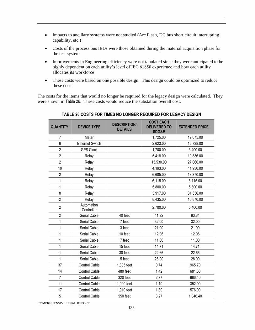
.
COMPREHENSIVE FINAL REPORT
133
• Impacts to ancillary systems were not studied (Arc Flash, DC bus short circuit interrupting
capability, etc.)
• Costs of the process bus IEDs were those obtained during the material acquisition phase for
the test system
• Improvements in Engineering efficiency were not tabulated since they were anticipated to be
highly dependent on each utility’s level of IEC 61850 experience and how each utility
allocates its workforce
• These costs were based on one possible design. This design could be optimized to reduce
these costs
The costs for the items that would no longer be required for the legacy design were calculated. They
were shown in Table 26. These costs would reduce the substation overall cost.
TABLE 26 COSTS FOR TIMES NO LONGER REQUIRED FOR LEGACY DESIGN
QUANTITY DEVICE TYPE DESCRIPTION/
DETAILS
COST EACH DELIVERED TO
SDG&E EXTENDED PRICE
7 Meter 1,725.00 12,075.00
6 Ethernet Switch 2,623.00 15,738.00
2 GPS Clock 1,700.00 3,400.00
2 Relay 5,418.00 10,836.00
2 Relay 13,530.00 27,060.00
10 Relay 4,193.00 41,930.00
2 Relay 6,685.00 13,370.00
1 Relay 6,115.00 6,115.00
1 Relay 5,800.00 5,800.00
8 Relay 3,917.00 31,336.00
2 Relay 8,435.00 16,870.00
2 Automation Controller
2,700.00 5,400.00
2 Serial Cable 40 feet 41.92 83.84
1 Serial Cable 7 feet 32.00 32.00
1 Serial Cable 3 feet 21.00 21.00
1 Serial Cable 10 feet 12.06 12.06
1 Serial Cable 7 feet 11.00 11.00
1 Serial Cable 15 feet 14.71 14.71
1 Serial Cable 30 feet 22.66 22.66
1 Serial Cable 5 feet 28.00 28.00
37 Control Cable 1,305 feet 0.74 965.70
14 Control Cable 480 feet 1.42 681.60
7 Control Cable 320 feet 2.77 886.40
11 Control Cable 1,090 feet 1.10 352.00
17 Control Cable 1,910 feet 1.80 576.00
5 Control Cable 550 feet 3.27 1,046.40
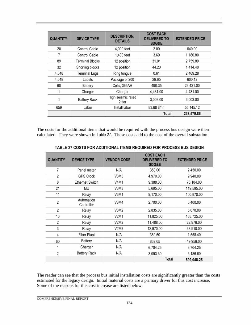
.
COMPREHENSIVE FINAL REPORT
134
QUANTITY DEVICE TYPE DESCRIPTION/
DETAILS
COST EACH DELIVERED TO
SDG&E EXTENDED PRICE
20 Control Cable 4,000 feet 2.00 640.00
7 Control Cable 1,400 feet 3.69 1,180.80
89 Terminal Blocks 12 position 31.01 2,759.89
32 Shorting blocks 12 position 44.20 1,414.40
4,048 Terminal Lugs Ring tongue 0.61 2,469.28
4,048 Labels Package of 200 29.65 600.12
60 Battery Cells, 365AH 490.35 29,421.00
1 Charger Charger 4,431.00 4,431.00
1 Battery Rack High seismic rated
2 tier 3,003.00 3,003.00
659 Labor Install labor 83.68 $/hr. 55,145.12 Total 237,579.86
The costs for the additional items that would be required with the process bus design were then
calculated. They were shown in Table 27. These costs add to the cost of the overall substation.
TABLE 27 COSTS FOR ADDITIONAL ITEMS REQUIRED FOR PROCESS BUS DESIGN
QUANTITY DEVICE TYPE VENDOR CODE COST EACH
DELIVERED TO SDG&E
EXTENDED PRICE
7 Panel meter N/A 350.00 2,450.00
2 GPS Clock V3M5 4,970.00 9,940.00
8 Ethernet Switch V4M1 9,388.00 75,104.00
21 MU V3M3 5,695.00 119,595.00
11 Relay V3M1 9,170.00 100,870.00
2 Automation Controller
V3M4 2,700.00 5,400.00
2 Relay V3M2 2,835.00 5,670.00
13 Relay V2M1 11,825.00 153,725.00
2 Relay V2M2 11,488.00 22,976.00
3 Relay V2M3 12,970.00 38,910.00
4 Fiber Plant N/A 389.60 1,558.40
60 Battery N/A 832.65 49,959.00
1 Charger N/A 6,704.25 6,704.25
2 Battery Rack N/A 3,093.30 6,186.60
Total 599,048.25
The reader can see that the process bus initial installation costs are significantly greater than the costs
estimated for the legacy design. Initial material costs are a primary driver for this cost increase.
Some of the reasons for this cost increase are listed below:
.
COMPREHENSIVE FINAL REPORT
135
• All SV relay and merging units are early generation equipment. The manufacturers are
currently charging a premium for these relays as the technology is implemented in their most
capable numerical relays
• The addition of IEC 61850 protocols to relays currently increases cost
• SV requires MUs to be installed in all the equipment, in the substation yard, that is associated
with the process bus
• Process bus adds a significant amount of DC load to the amount allocated for P&C. This is
due to the additional Ethernet equipment and MUs. In this estimate the P&C load increased
by approximately 170%. This increase in load required a larger DC plant to supply the load.
Despite the increase in initial material costs, it was anticipated that process bus material costs will
reduce as adoption rates increase and the equipment becomes more common. But even with a
significant decrease in material costs, IEC 61850 requires additional P&C infrastructure to support
the equipment for a process bus implementation. This will likely remain a cost increase when
compared to the legacy design.
The labor costs associated with the process bus implementation were reduced significantly. This was
primarily due to the reduction in wiring. However, this cost reduction was not as significant as the
increase in material costs.
Future savings were anticipated to offset these costs as the engineering effort was reduced by
leveraging utility specific standards and templates which were less complex. Substation apparatus
could be specified to include factory installation of MUs, further driving down costs. Current
industry estimates suggest that IEC 61850 with process bus can reduce engineering time by as much
as 75%. In addition, future substation additions and changes will require significantly less effort and
cost as much of the new work would be implemented in software.
Finally, IEC 61850 prepares the utility for a digital future that will support features and applications
that are only starting to become available. These could include additional diagnostic features and
self-test capabilities.
Taking the long view, it would be conceivable that relays will only be available from manufacturers
with IEC 61850 features and no hardwired connections in the next 15-20 years, much like what has
occurred with the transition to numerical relays from electromechanical and static models. This
technology transition was driven not only by improved features and capabilities, but the
semiconductor manufacturing industry’s tendency to continue to shorten the production lifespan of
critical components.
Pros and Cons
Like any new endeavor, migrating to an IEC 61850 process bus P&C scheme includes benefits and
drawbacks. This section identifies some of these items.
Pros
Wiring
A very significant advantage to IEC 61850 was reduction in hard wired control circuits and its
attendant complexity. All of this complexity gets moved to configuring the protective relays and IEC
61850 communications between devices. Obviously, this saves on wiring, terminating, labeling, and
reduces the chances of wiring errors. It also reduces fabrication time and expense for protection
.
COMPREHENSIVE FINAL REPORT
136
panels and reduces construction and testing time at the substation. With the reduction in field wiring,
the required time in the field for installation and testing of protection panels could be reduced from
weeks to days.
CT Performance
One big advantage with SV protection was that current and potential signals were transmitted across
the process bus network in primary engineering units, allowing maximum CT and PT ratios to be
used without compromising accuracy or impacting signal fidelity and internal protective relay setting
limitations. This has an obvious advantage with impedance relaying, where protection settings
developed in secondary units were dependent on the instrument transformer connected ratios, where
CTs were frequently tapped down to bring the maximum secondary impedance within the relay’s
fixed setting range. Because of a multi-ratio CT’s poorer electromagnetic performance (saturation) at
lower ratios, avoiding reduced taps was a great advantage. With the move towards SV, future relays
could be set in primary units, eliminating a major issue in existing protection methodology.
Semantic Model
IEC 61850 provides a semantic model for standardized structured data exchanges between devices.
This allows for standard object model names. Thus the data becomes visible without configuration,
which enables self-description of the IEDs. An IEC 61850 protocol browser can be used to view the
capabilities of an IEC 61850 device even before the device was placed in service at the substation.
The schema also allows the configuration files to be standardized into IEC 61850 file types. These
file types can be used to support configuration and engineering efforts.
GOOSE
By its nature high speed GOOSE messages were ideal for relay to relay and relay to MU message
transfer. It allowed for supervision of the link due to its periodic retransmission properties. Studies
of GOOSE timing have identified that it typically performs far faster than hardwired I/O, which was
limited by the time to close electromechanical contacts. Within the industry, GOOSE was currently
fairly mature and a GOOSE application would be an ideal candidate for an early implementations.
Currently, the IEC 61850 standard development teams were working on an implementation of
GOOSE for substation to substation control communication.
Sampled Values
SV messages separate the sampling of analog values from their calculation and metering. They allow
analog values to be measured one time and shared among applications. Not only does this reduce
wiring effort and time, it also allows for consistent high quality data with a minimum of infrastructure
and the time to verify calibration during routine maintenance.
Engineering Effort
Engineers will be able to test protective system development in a basic lab environment while
developing settings before they were deployed in an actual substation. This will reduce schedule
pressure and errors. It will also allow P&C schemes to be developed as standard templates which will
significantly reduce future deployment time and improve quality.
Interoperability
One of the most significant goals of the IEC 61850 Standard was interoperability. If consistently
implemented, it would allow IEDs from different manufacturers to communicate, exchange data, and
make use of the information. It would simplify the design, construction, implementation,
commissioning, testing, and maintenance of P&C systems in substations. Allowing users to select
any manufacturer’s device, apply it with any other manufacturer’s device, and be assured that the
devices would interoperate would be an enormous benefit to the industry and all users.
.
COMPREHENSIVE FINAL REPORT
137
Lockout relays
At the request of the project team, lockout relay functionality was implemented within certain relays.
This allowed the project team to better visualize the way that a “digital” lockout scheme would
perform. While this was not a unique benefit associated with an IEC 61850 P&C scheme, it does
demonstrate the capability of advanced numerical relays. The adoption of this type of lockout
relaying would eliminate traditional hardwired lockout relays, cumbersome wiring and simplify the
NERC PRC-005 testing.
Cons
Limited Interoperability at this Time
The drawbacks to IEC 61850 for the project team included limitations of the current industry
technology across manufacturers, the need for modifications to current standards and practices, and
the required training of personnel for the large technology shift. The results of this study showed that
not all relay manufacturers support sampled values in a completely interoperable manner. Some
manufacturers’ relays were also much easier to learn and configure than others – an important
consideration during the selectin process. Furthermore, interoperability across relay manufacturers
was inconsistent. This study found that IEC 61850 SV technologies were still developing in the
industry and further development was needed for consistent interoperability between relay
manufacturers.
Migration Process
This EPIC-2, Project 1 served as a technology demonstration and feasibility study. In this case,
adopting IEC 61850 process bus appears feasible. The next step in the process would be to determine
a precise list of the exact functions and features of IEC 61850 that SDG&E would like to adopt. This
list should include those functions and features that were beyond the scope of this project.
SDG&E now has the opportunity to evaluate their current standards and determine how they can be
modified to accommodate future technologies like IEC 61850. This could include:
• Provisioning future rack/panel space to accommodate the additional communication
equipment that will be required in the control shelter
• Increasing the size of control cabinets in transformer, breakers, and other equipment so that
the addition of merging units and associated equipment may be easily installed
• Verification that a standard control shelter size can accommodate the larger battery system
required for an IEC 61850 application
• Development of a training program around IEC 61850 to cover the technology itself, testing,
and operations
• Identification and implementation of small pilot applications, to develop experience with IEC
61850. Implementation of the capacitor/reactor automation logic would be a very achievable
project that would allow SDG&E to gain valuable experience in a low risk manner
• Development of a larger pilot project to test the technology in full substation implementation.
This pilot project should serve as the basis for developing new standards for station drawings,
relay settings, SCADA, and communication configurations. A small substation located in
close proximity to a maintenance center would be an ideal candidate for this type of pilot
project
.
COMPREHENSIVE FINAL REPORT
138
• The relays in SDG&E’s standards do not currently have IEC 61850 process bus capabilities.
This means that new standard drawing packages, relay configurations, and define new
equipment standards for IEC 61850 applications will need to be created. The project team
may even have to switch to different protection philosophies and suppliers when
implementing IEC 61850. An example was the high-impedance bus differential relay applied
on some transmission buses. This application would still require a significant amount of CT
wiring, in the field to a central summing point, for conversion of the analog signals into an
MU readable signal
• Currently IEC 61850 is not used extensively in SDG&E’s substations. Adoption of IEC
61850 will mean new technology for the protection and substation design engineers to learn
and develop expertise around. Furthermore, field support personnel, such as operators and
relay technicians, will also experience the technology change. For operations, testing,
procedures will have to be modified to fit the new technology. As an example, when MUs
were installed in field devices for SV and GOOSE, some testing will need to be performed at
the breakers and transformers located in the substation yard, instead of in the air-conditioned
control shelter.
.
COMPREHENSIVE FINAL REPORT
139
12. KEY FINDINGS Based on a review of the pre-commercial demonstration test results and execution of the test system
design and relay settings/IEC 61850 configurations, the following key findings were developed:
• Multi-vendor interoperability is not universal for the products tested in this project. Because
these initial integration efforts were significant, future implementations should benefit from
these experiences.
• Use of IEC 61850 SV did not impact relay performance, as compared to a direct hardwired
solution, as long as the process bus network was correctly designed and utilizes managed
switches for MAC address filtering as necessary.
o Other than the obvious wiring and data communications advantages that IEC 61850
GOOSE and SV have over conventional hardwired relay installations, protection
settings and schemes did not change with an IEC 61850 process bus installation, as
basic protection concepts did not change.
• All SV based test cases evaluated were able to be implemented with IEC 61850 process bus.
The technology evaluated was at a point where it could be applied to utility protection
applications, assuming careful attention to equipment selection for compatibility.
• GOOSE messages successfully replaced traditional hard wire status and control wiring in the
project. Analog values that were embedded within GOOSE data sets, successfully controlled
a reactive automation application.
• IEC 61850 process bus compatible relays and merging units were still so new that the
manufacturers’ technical sales representatives were only generally familiar with application
and configuration. One should expect to initially spend a considerable amount of engineering
time on resolving IEC 61850 process bus configuration issues and locating manufacturer staff
that will be able to provide the required engineering support.
• Manufacturers have not coalesced around fully interoperable SV options; IEC 61850-9LE
still has a large potential for differences that allows manufacturers’ equipment to meet the
standard, yet not work with each other without a large amount of end-user effort.
• IEC 61850 GOOSE/MMS messaging was stable with good interoperability between different
manufacturers’ equipment. Configuration tools were fairly easy to learn and use.
• Relay manufacturers’ documentation, as far as implementing an SV application, was lacking
and many critical items can be expected to be discovered only by extensive communication
with the manufacturers to learn unpublished information and facts.
• SV compatible relays require the capability to subscribe to at least six SV channels, with the
ability to internally map the various voltage and amperage signals to the proper protection
elements without limitations, if the technology was to maximize its potential to replace
hardwired equipment. The overcurrent bus differential use case proved this fact.
• MUs should support, at a minimum, a built-in SER for GOOSE I/O troubleshooting. Built-in
capability to implement basic Boolean logic and an ER would be very desirable features too.
Some of the test system MUs supported Boolean logic, an ER, and a time stamped SER.
• MUs should integrate analog inputs with digital inputs and outputs into a small panel
mounted enclosure for easy field installation in yard apparatus such as transformers and
circuit breakers. Only two manufacturers’ MUs evaluated in this study were close to meeting
this requirement.
.
COMPREHENSIVE FINAL REPORT
140
• Only one manufacturer’s MU used in the study was easily interfaced with all three
manufacturers relays evaluated in the study. MUs generally worked very well with relays
built by the same manufacturer.
• Manufacturers’ relay and MU configuration software packages were still a “work in
progress.” One major relay manufacture’s software evaluated was found to be very difficult
to work with, with multiple non-integrated applications, which required direct assistance by
the manufacturer’s staff to complete the configuration tasks. This level of complexity would
not be acceptable in an implementation environment. Other relay manufacturers’ software
packages were fairly user friendly and intuitive. The majority of the issues encountered
during configuration were eventually resolved with assistance from the manufacturers’
support staff.
• Ethernet switches necessary to integrate all the parts of an IEC 61850 SV substation have a
power demand significantly higher than the relays and MUs themselves, which could impact
station battery sizing and should not be ignored.
• The network and time synchronization system proposed for the test system provided a broad
range of support to cover the various vendors’ networking and time synchronization
interfaces. It also provided the quantities and types of equipment to simulate the required
process bus architectures and fiber implementation that would occur in a real substation
installation.
• The initial material costs of a substation designed with IEC 61850 GOOSE and SV P&C was
calculated to be greater than the initial material costs of a traditional P&C substation.
• Some manufacturers’ relays require different ports for SV and GOOSE signals intended for
the same process bus connection. This was a disadvantage that must be rectified in future
models because it impacts the ability to connect the relays to both the station and process
buses, provide a port for dedicated maintenance access.
• The results support this project’s EPIC value proposition in that the P&C scheme evaluated
was anticipated to be at least as reliable, if not more so, than the existing legacy P&C scheme.
Although the initial costs of a P&C scheme as described in this project may be higher, it was
anticipated that the on-going costs will be reduced.
• The project’s goals to investigate interoperability and determine protection system
performance were achieved:
o The interoperability determination was successful. Although interoperability was not
universally achieved for all of the devices, enough interoperability was achieved to
allow for testing of all of the protection use cases identified in the project scope.
o Performance of the protection relays using an IEC 61850 P&C scheme were verified
to equal or exceed the performance requirements set by the project team.
IEC 61850 Implementation Challenges
Transitioning protection design philosophy from using direct CT/PT and I/O connections to each
protection relay to using IEC 61850 GOOSE and SV still presents many challenges.
The first challenge would be to design the infrastructure that would serve as the signal transport
medium, replacing the hardwired copper cable. Process bus design and equipment assignment was an
important first step which drove parts of the network equipment specification. The manufacturers had
different limitations on how the equipment could interface with the process bus which introduced
network complexity and interoperability issues. Another important component required by IEC
.
COMPREHENSIVE FINAL REPORT
141
61850 SV was time synchronization. A mix of time synchronization requirements was identified
from the various manufacturers included in this project, which covered the entire list of methods
called out in the standard. The test system design team found a GPS clock source that could support
all of these time source types and provide network isolation between the various networks.
With the release of edition 2, for many of the IEC 61850 parts, new challenges arose in determining
which edition to use for the project. In a single manufacturer solution this would generally not be a
problem but with a multi-manufacturer project, it was vital that all of the manufacturers function
together under the same SCL model, SV and GOOSE edition. A further challenge in choosing the
edition was that most manufacturers were still only providing SV using the UCA International Users
Group (UCAIug), “IMPLEMENTATION GUIDELINE FOR DIGITAL INTERFACE TO
INSTRUMENT TRANSFORMERS USING IEC 61850-9-2” (LE) which is based on IEC 61850-9-2
Edition 1. A mix of implementations with both edition 1 and edition 2 functions were identified and
that added an additional degree of difficulty for the test system implementation.
Another challenge was providing the correct SCL file type and edition necessary to import into other
manufacturers’ configuration tools. The manufacturers had limitations in their configuration tools for
exporting the SCL file type, edition, and providing optional information that was required by other
manufacturer configuration tools. In some cases, manual modifications to the SCL files, to allow
proper information exchanges, was required. There were numerous character length limitations for
the various GOOSE and SV parameter settings which, when exceeded did not produce any errors
within the configuration tool. These problems could only be found with the identification of an
unrelated problem and working backwards to determine the cause, including application of a network
analysis tool. The lack of built-in error checking in the configuration tools required significant
additional testing to determine the root cause of problems. Some confusion was identified with one
manufacturer’s tools, where separate software packages were used for each type of configuration task.
In some cases it was not clear how to link the information between the software packages. Appendix
H contains a list of observations identified during configuration and testing. This list was anticipated
to provide assistance to the engineers responsible for device configuration in future projects.
Protection and merging unit electrical and protection settings were very similar to what was required
for the base systems. Some of the protection relays still had some setting requirements around CT
and PT ratios, which seemed redundant given that the merging units provided primary values for the
samples. This and other settings such as the reference SV stream were different from what the
protection engineers were used to but once done, the settings were the same as they have done before.
Testing was another challenge. The development of new procedures to ensure the infrastructure was
working correctly was followed by the execution of the protection scheme testing. Good
documentation was the key to success and much effort was expended to develop proper dataflow
tables and diagrams to communicate all the virtual wiring, GOOSE, and SV used in the system
between the various members of the system configuration team. These documents along with the
networking and time synchronization diagrams provided the base information to create the testing
procedures, and will be crucial when performing actual implementations.
All IEC 61850 implementations challenges were easily solved during the initial equipment selection
process and design. Like the traditional design methods, determine the equipment to use, identify
which IEC 61850 functions to implement, and determine how the user can work out solutions. Once
complete the challenges associated with the first project will be minimized.
.
COMPREHENSIVE FINAL REPORT
142
13. CONCLUSIONS Upon review of the demonstration findings, the following conclusions are made:
• The results of this project were very encouraging. SV based P&C were found to be
equivalent or better than the legacy hardwired solutions for the use cases identified. IEC
61850 did not degrade and in some cases improved protection, control and automation
schemes.
• SV messages were more flexible than the existing traditional hardwired P&C system.
• GOOSE messages were more flexible and faster than the existing traditional hardwired P&C
system.
• IEC 61850 SV and GOOSE increased P&C system flexibility and provided opportunities for
new P&C schemes due to digitization of the system.
• Although not yet universal, substantial SV interoperability was identified. It was anticipated
that interoperability will only improve with time.
• The interoperability results of this project should be of interest to all potential users of SV.
The project findings should assist manufacturers with their SV implementations so as to
improve interoperability. These results should also assist adopters of IEC 61850 with the
selection and evaluation of future manufacturer product offerings.
• Once the team was sufficiently experienced with the products’ configuration details
configuration time decreased. Configuration templates would be especially valuable in this
regard.
• The project provided opportunities to learn more about IEC 61850’s limitations, capabilities
and vendors’ interoperability.
.
COMPREHENSIVE FINAL REPORT
143
14. RECOMMENDATIONS The project team recommends that SDG&E continue to explore commercial adoption of IEC 61850
applications within its substations. The project findings and conclusions show that, although care is
required in the selection of products, the currently available merging units and relays are sufficiently
mature to support interoperability between vendors. In addition, the protection performance of the
test system is equivalent to hardwired legacy P&C systems.
The project team further recommends that an SDG&E communications laboratory be developed to
support future work and training. This laboratory would include a capability to mock-up future
substation communications infrastructure to validate their performance before actual deployment in
substations. Although this laboratory would have a focus on IEC 61850, it would also support testing
of other communications technologies and standards.
With the completion of the future work items, discussed in the next section, the project team
recommends that pilot projects be initiated to gain experience with IEC 61850. Potential pilot
projects could include a GOOSE based 12 kilovolt (kV) capacitor control scheme using existing
installed hardware, or a three breaker 69 kV P&C scheme. These pilot projects could be precursors
towards development of a larger project to test the technology in an actual substation. A pilot project
will serve as the basis for developing new standards for station drawings, relay settings, SCADA and
communication configurations. A substation located in close proximity to a maintenance center
would be an ideal candidate for this type of pilot project because of the training opportunities it
provides.
An IEC 61850 design implementation will differ greatly from current hardwired state of the art, and
issues such as maintenance, testing and training, must be addressed while embarking on the first
implementation of this technology.
SDG&E should make the results of this EPIC project available to the various standards bodies
associated with IEC 61850 – especially IEC Technical Committee 57, Working Group 10.
Future work
The following future work items represent valuable next-step options in the adoption of a full IEC
61850 substation. These items would allow the user to gain valuable experience with the IEC 61850
standard. Each item was sized such that a small team of two to three subject matter experts could be
identified and assembled to research and develop the necessary components in a relatively short
period of time.
Network Optimization
In accordance with the project team’s direction, the test system network design was the minimal
necessary to complete the testing. Although basic multi-cast filtering was configured, configuration
items did not include advanced networking features or optimization. For an actual substation
implementation consideration should be given to additional network design and optimization.
Suggested items of particular interest may include VLANs, priorities, and multi-cast filtering.
Remote Access
In accordance with the project team’s direction, remote access was not explored. It was understood
that the project team was investigating this capability as part of a separate project. Internal policies
and NERC CIP requirements would need to be investigated in order to determine the level of
protection required and the preferred method of achieving this capability.
.
COMPREHENSIVE FINAL REPORT
144
Redundancy
Redundancy was a broad topic that covers many disciplines. It can include protection design, local
network design, and WAN design. Currently the project team has a protection philosophy that
provides a degree of redundancy. This philosophy could be combined with local networking to
achieve the degree of redundancy necessary to meet the project team’s requirements. Combining the
protection redundancy requirements with network redundancy could yield synergies and provide
significant benefits.
SCADA
The project’s scope did not include exploration of metering, data acquisition, or local annunciation.
Each of these items presents an opportunity to combine with the IEC 61850 P&C developed in this
project to enhance the current design and lower costs.
• Individual panel meters were a standard of the current substation design. The relays included
in this project included large LCD screens, which could be used to display local metering.
Another option could include stand-alone displays that were connected to serial ports on the
relays. Other options could be explored to balance features and costs.
• A station data concentrator, RTU, or gateway that supports GOOSE messages and/or MMS
would enable the project team to further reduce station wiring. Multiple products were
currently available that support this solution. An engineering study and lab test of these
products would enable the project team to identify an acceptable product.
• Similarly, the current use of panel annunciators could be modified to eliminate the serial
communications driven annunciators. GOOSE messaging was a potential opportunity to
further reduce wiring within the substation.
SV Implementations
This project utilized IEC 61850-9-2, Edition 2 for SV. Many interoperability issues arose from
inconsistent design choices between manufacturers concerning the edition 2 implementations. IEC
published standard 61869-9 in 2016. This standard provides guidance on the digital interface for
instrument transformers. It would be worthwhile to investigate products that have implemented this
standard to determine if interoperability would be improved.
.
COMPREHENSIVE FINAL REPORT
145
15. POST-PROJECT TECHNOLOGY TRANSFER The project team will submit presentations and papers to major conferences and/or journals. These
submissions include, but are not limited to, the annual EPIC Symposium.
The availability of this report on the SDG&E EPIC website https://www.sdge.com/epic will be
widely announced.
A PowerPoint presentation will be developed and used to aid in engaging the stakeholder groups
within SDG&E. This presentation will also aid in coordination with external stakeholders in IEC
61850.
.
COMPREHENSIVE FINAL REPORT
146
16. METRICS AND VALUE PROPOSITION:
Metrics:
The following metrics were identified for this project. Given the proof of concept nature of this EPIC
project, these metrics are forward looking to prospective adoption of IEC 61850 standards.
The main protection concerns that were identified in this project were speed and reliability. The
following items address these concerns.
Potential energy and cost savings
Due to saving on the engineering efforts of the design process using IEC 61850 equipment, which can
be reflected to the price of energy for ratepayer.
The main saving comes from the integrated engineering tools that makes it easier to design the
substation and test the equipment before deployment, which is hard to achieve now and its is time
consuming using the current legacy systems.
Economic benefits
Maintain/Reduce operations and maintenance costs
IEC 61850 digital equipment allows easier maintenance and debugging of the equipment
using advanced embedded software tools.
The labor costs associated with the process bus implementation were reduced significantly.
This was primarily due to the reduction in wiring.
Improvements in system operation efficiencies and adding automation features
Operation efficiency can be improved using IEC 61850 equipment especially with the new
peer-to-peer communication feature, which allows major improvements of operations, and
more equipment can be monitored and operated to reduce the cause of outages and improve
the efficiency. This also allow more automation in the substation and things like triggering
CAP banks and Voltage regulators can be improved.
Value proposition:
The purpose of EPIC funding is to support investments in R&D projects that benefit the electricity
customers of SDG&E, PG&E, and SCE. The primary principles of EPIC are to invest in technologies
and approaches that provide benefits to electric ratepayers by promoting greater reliability, lower
costs, and increased safety. As discussed and summarized below, this project met all three of the
EPIC primary principles: reliability, lower cost, and safety, and two of the EPIC secondary principles
were applied.
Primary principles
• Reliability:
The new equipment performed all the protection schemes in current substations with a
faster initiation time and more operation capabilities.
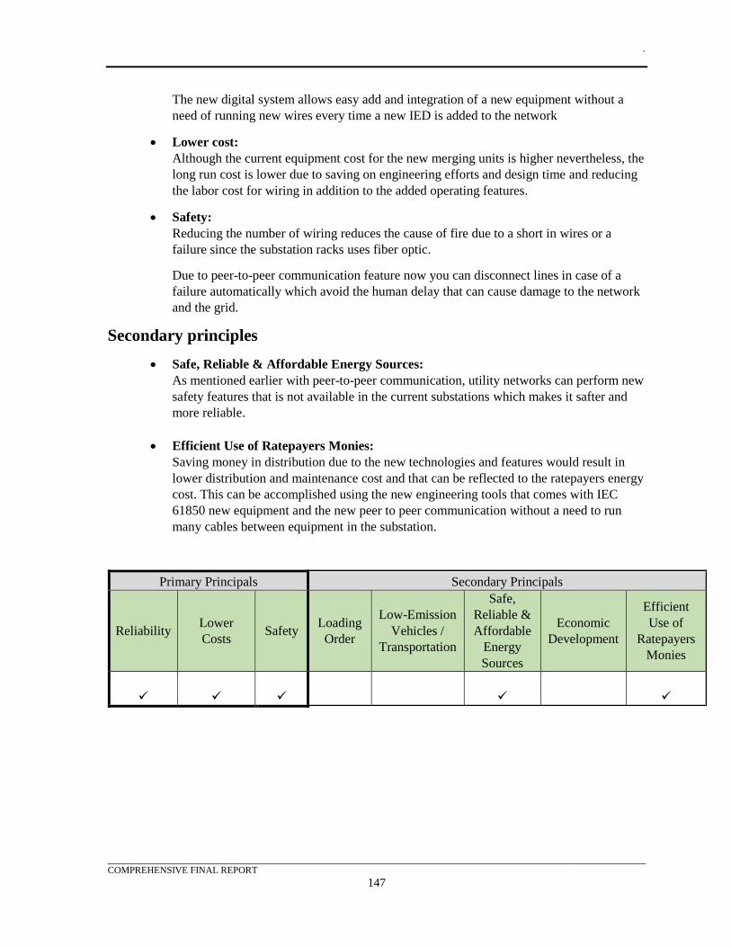
.
COMPREHENSIVE FINAL REPORT
147
The new digital system allows easy add and integration of a new equipment without a
need of running new wires every time a new IED is added to the network
• Lower cost:
Although the current equipment cost for the new merging units is higher nevertheless, the
long run cost is lower due to saving on engineering efforts and design time and reducing
the labor cost for wiring in addition to the added operating features.
• Safety:
Reducing the number of wiring reduces the cause of fire due to a short in wires or a
failure since the substation racks uses fiber optic.
Due to peer-to-peer communication feature now you can disconnect lines in case of a
failure automatically which avoid the human delay that can cause damage to the network
and the grid.
Secondary principles
• Safe, Reliable & Affordable Energy Sources:
As mentioned earlier with peer-to-peer communication, utility networks can perform new
safety features that is not available in the current substations which makes it safter and
more reliable.
• Efficient Use of Ratepayers Monies:
Saving money in distribution due to the new technologies and features would result in
lower distribution and maintenance cost and that can be reflected to the ratepayers energy
cost. This can be accomplished using the new engineering tools that comes with IEC
61850 new equipment and the new peer to peer communication without a need to run
many cables between equipment in the substation.
Primary Principals Secondary Principals
Reliability Lower
Costs Safety
Loading
Order
Low-Emission
Vehicles /
Transportation
Safe,
Reliable &
Affordable
Energy
Sources
Economic
Development
Efficient
Use of
Ratepayers
Monies
✓ ✓ ✓ ✓ ✓
.
COMPREHENSIVE FINAL REPORT
148
REFERENCES
[1] IEC. (2016, 04). IEC 61869-9 ed 1. Instrument transformers –Part 9: Digital interface for
instrument transformers. IEC.

.
COMPREHENSIVE FINAL REPORT
149
BIBLIOGRAPHY Group, R. C.-T. (2004). IRIG Standard 200-04. IRIG SERIAL TIME CODE FORMATS. Range
Commanders Council-Telecommunications and Timing Group.
IEC. (2003, 08). IEC/TS 61850-2 ed 1. Communication networks and systems- Part 2: Glossary.
IEC. (2009, 12). IEC 61850-6 ed 2. Communication networks and systems for power utility
automation – Part 6:Configuration description language for communication in electrical
substations related to IEDs. IEC.
IEC. (2010, 08). IEC 61850-7-2 ed 2. Communication networks and systems for power utility
automation –Part 7-2: Basic information and communication structure – Abstract
communication service interface (ACSI), 2. IEC.
IEC. (2010, 12). IEC 61850-7-3 ed 2. Communication networks and systems for power utility
automation –Part 7-3: Basic communication structure – Common data classes, 2. IEC.
IEC. (2010, 03). IEC 61850-7-4 ed 2. Communication networks and systems for power utility
automation –Part 7-4: Basic communication structure – Compatible logical node classes and
data object classes, 2. IEC.
IEC. (2010, 03). IEC/TR 61850-90-1 ed 1. Communication networks and systems for power utility
automation –Part 90-1: Use of IEC 61850 for the communication between substations. IEC.
IEC. (2011, 04). IEC 61850-4 ed 2. Communication networks and systems for power utility
automation –Part 4: System and project management. IEC.
IEC. (2011, 07). IEC 61850-7-1 ed 2. Communication networks and systems for power utility
automation –Part 7-1: Basic communication structure – Principles and models. IEC.
IEC. (2011, 06). IEC 61850-8-1 ed 2. Communication networks and systems for power utility
automation –Part 8-1: Specific communication service mapping (SCSM) – Mappings to MMS
(ISO 9506-1 and ISO 9506-2) and to ISO/IEC 8802-3, 2. IEC.
IEC. (2011, 09). IEC 61850-9-2 ed 2. Communication networks and systems for power utility
automation –Part 9-2: Specific communication service mapping (SCSM) – Sampled values
over ISO/IEC 8802-3. IEC.
IEC. (2012, 12). IEC 61850-10 ed 2. Communication networks and systems for power utility
automation – Part 10: Conformance testing(Edition 2). IEC.
IEC. (2012, 05). IEC/TR 61850-90-5 ed 1. Communication networks and systems for power utility
automation –Part 90-5: Use of IEC 61850 to transmit synchrophasor information according
to IEEE C37.118. IEC.
IEC. (2013). IEC 61131-3. Programmable controllers - Part 3: Programming languages . IEC.
IEC. (2013, 12). IEC 61850-3 ed 2.0. Communication networks and systems for power utility
automation –Part 3: General requirements. IEC.
IEC. (2013, 01). IEC 61850-5 ed 2. Communication networks and systems for power utility
automation –Part 5: Communication requirements for functions and device models. IEC.
IEC. (2013, 03). IEC/TR 61850-1 ed 2. Communication networks and systems for power utility
automation –Part 1: Introduction and overview. IEC.
IEC. (2013, 08). IEC/TR 61850-90-4 ed 1. Communication networks and systems for power utility
automation –Part 90-4: Network engineering guidelines. IEC.
.
COMPREHENSIVE FINAL REPORT
150
IEC. (2015, 03). IEC 62271-3 ed 2. High-voltage switchgear and controlgear –Part 3: Digital
interfaces based on IEC 61850. IEC.
IEC. (2015, 06). IEC PAS 61850-9-3 ed 1. Communication networks and systems for power utility
automation –Part 9-3: Precision time protocol profile for power utility automation. IEC.
IEC. (2016, 04). IEC 61869-9 ed 1. Instrument transformers –Part 9: Digital interface for instrument
transformers. IEC.
IEC. (2016, 02). IEC TR 61850-90-2 ed 1. Communication networks and systems for power utility
automation –Part 90-2: Using IEC 61850 for communication between substations and
control centres. IEC.
IEC. (2016, 05). IEC TR 61850-90-3 ed 1. Communication networks and systems for power utility
automation –Part 90-3: Using IEC 61850 for condition monitoring diagnosis and analysis.
IEC.
IEC. 61869-9: Instrument transformers - Part 9: Digital interface for instrument transformers
IEC. 62439-3: Clause 4 Parallel Redundancy Protocol (PRP) and Clause 6 High-availability Seamless
Redundancy (HSR) Protocol.
IEEE. (2006). IEEE 1613. Approved Draft IEEE Standard Environmental and Testing Requirements
for Communications Networking Devices in Electric Power Substations. IEEE.
IEEE. (2007). IEEE 1686-2007. IEEE Standard for Intelligent Electronic Devices Cyber Security
Capabilities. IEEE.
IEEE. (2011). IEEE C37.118. Standard for Synchrophasor Measurements for Power Systems. IEEE.
IEEE. (2012). IEEE Std 1815-2012. IEEE Standard for Electric Power Systems Communications-
Distributed Network Protocol (DNP3) . IEEE.
IEEE. (2013). IEEE 1686-2013. IEEE Standard for Intelligent Electronic Devices Cyber Security
Capabilities. IEEE.
IEEE. (2013, 01). IEEE Std C37.94 - IEC 62843. Standard for N times 64 kilobit per second optical
fiber interfaces between. IEEE.
IEEE. (2015). IEEE 1588 PC37.238/D16. IEEE Draft Standard Profile for Use of IEEE 1588
Precision Time Protocol in Power System Applications. IEEE.
IEEE. (2015). IEEE 1815.1-2015. IEEE Approved Draft Standard for Exchanging Information
between Networks Implementing IEC 61850 and IEEE Std 1815(TM) (Distributed Network
Protocol - DNP3) - Corrigendum 1 . IEEE.
IEEE. (2016, 08). IEEE PC37.238. IEEE Draft Standard Profile for Use of IEEE 1588 Precision
Time Protocol in Power System Applications. IEEE.
IEEE. 802.1Q IEEE Standard for Local and metropolitan area networks—Bridges and Bridged
Networks
NERC. “NERC CIP-007-6 R5.5”
NIST. “NIST SP 800-82r2, Guide to Industrial Control Systems (ICS) Security”, File Name:
NIST.SP.800-82r2, last modified May 2015.
Organization, M. (2012, 04). Modbus. MODBUS APPLICATION PROTOCOL SPECIFICATION
V1.1b3. Modbus Organization.
.
COMPREHENSIVE FINAL REPORT
151
UCA International Users Group. “IMPLEMENTATION GUIDELINE FOR DIGITAL INTERFACE
TO INSTRUMENT TRANSFORMERS USING IEC 61850-9-2”, File Name:
DigIF_spec_9-2LE_R2-1_040707-CB, Modification Index: R2-1, 2004-07-07, Last
Modified 2011-03-14.
.
APPENDIX A
A-1
APPENDIX A - TEST CASE DATA FLOW DIAGRAMS The test case data flow diagrams contained in this appendix illustrate the flow of information and
which relays and merging units are associated with the case. Use cases that deal with particular
conditions, such as the phases of a fault, are not illustrated. Even though the diagram shows all
merging units and relays, only the merging units and protection relays which were included in the test
are shaded with a blue background and gray cross-hatches. IEC 61850 SV messages are indicated
with dotted blue lines. GOOSE messages are indicated with solid black lines. SV and GOOSE
message names are indicated near the transmitting device. Arrows on SV and GOOSE messages
indicate a device was subscribing to that message.
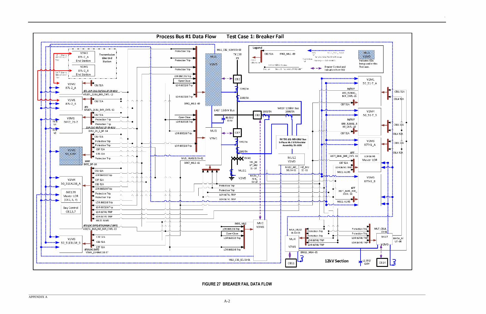
.
APPENDIX A
A-2
FIGURE 27 BREAKER FAIL DATA FLOW
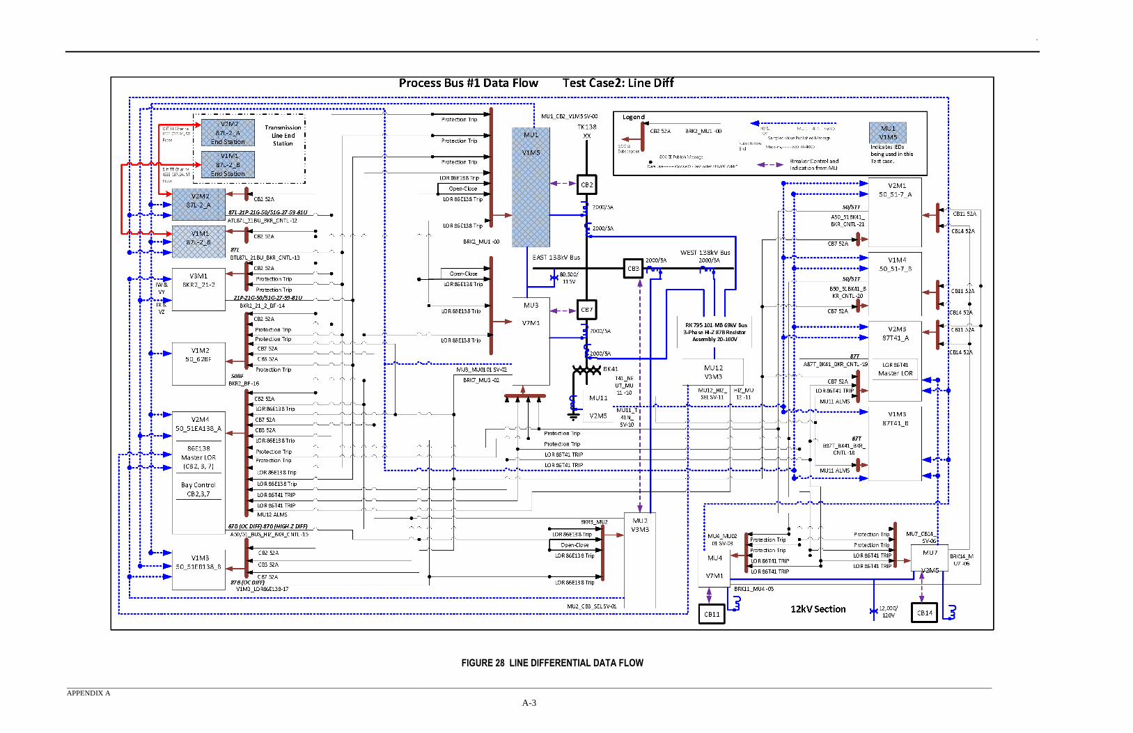
.
APPENDIX A
A-3
FIGURE 28 LINE DIFFERENTIAL DATA FLOW
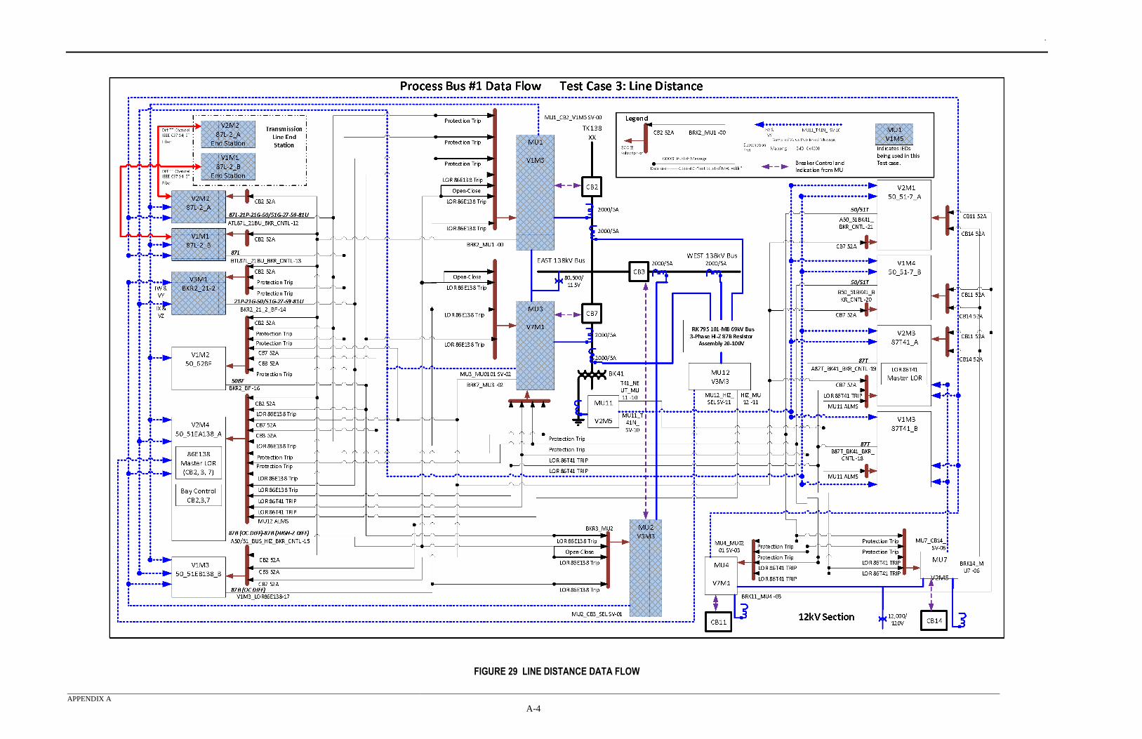
.
APPENDIX A
A-4
FIGURE 29 LINE DISTANCE DATA FLOW
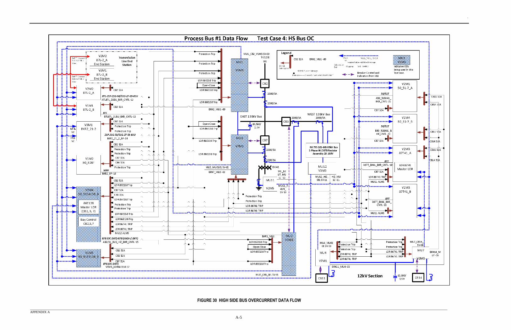
.
APPENDIX A
A-5
FIGURE 30 HIGH SIDE BUS OVERCURRENT DATA FLOW
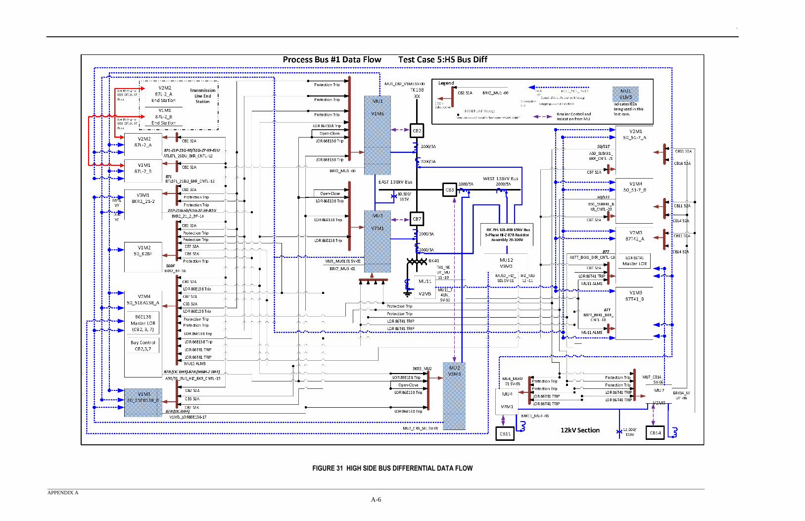
.
APPENDIX A
A-6
FIGURE 31 HIGH SIDE BUS DIFFERENTIAL DATA FLOW
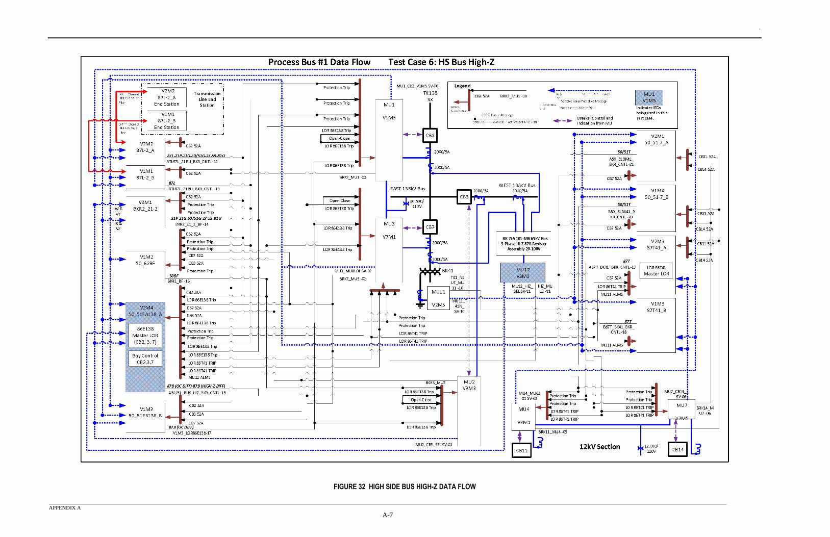
.
APPENDIX A
A-7
FIGURE 32 HIGH SIDE BUS HIGH-Z DATA FLOW
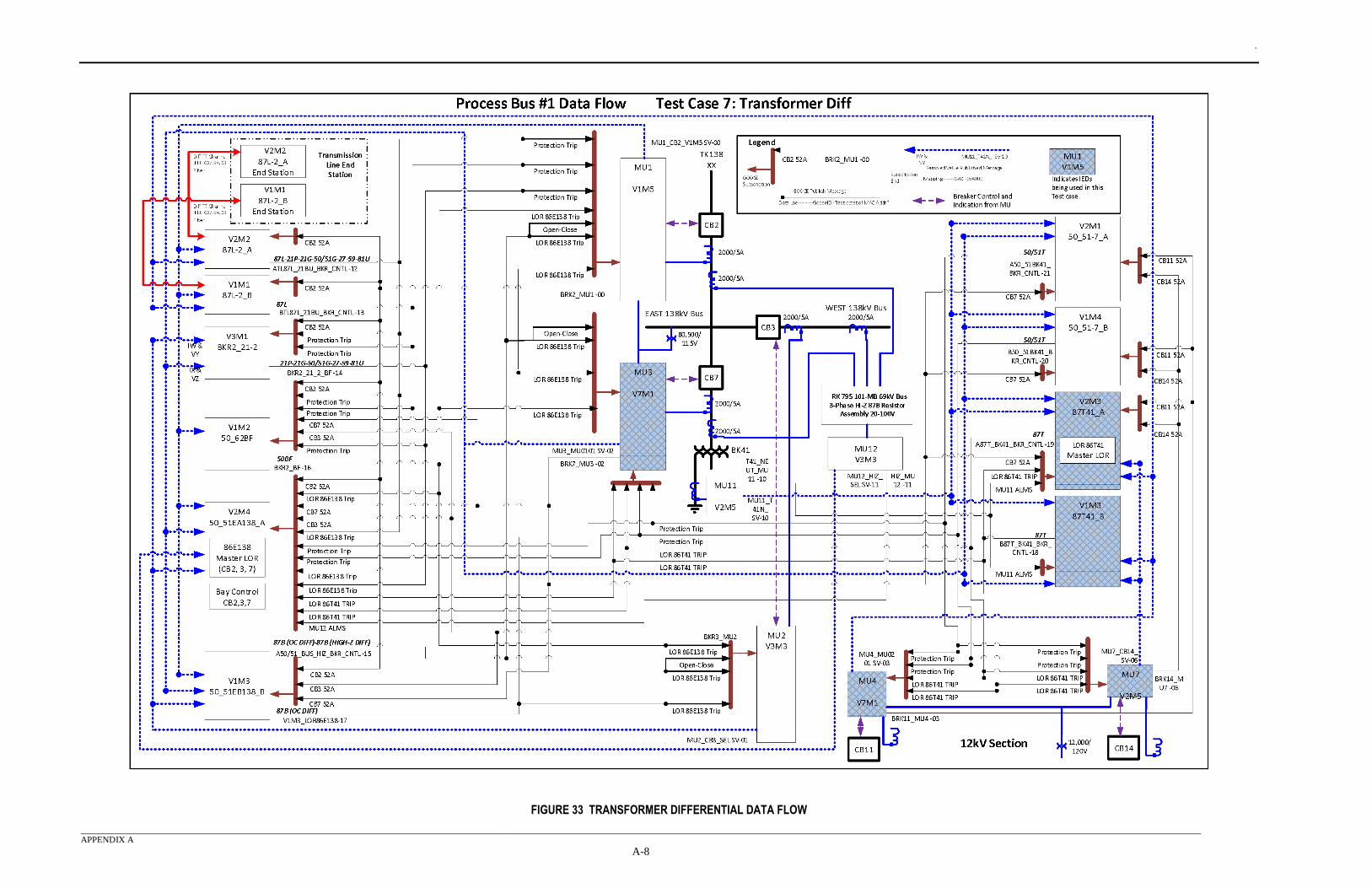
.
APPENDIX A
A-8
FIGURE 33 TRANSFORMER DIFFERENTIAL DATA FLOW
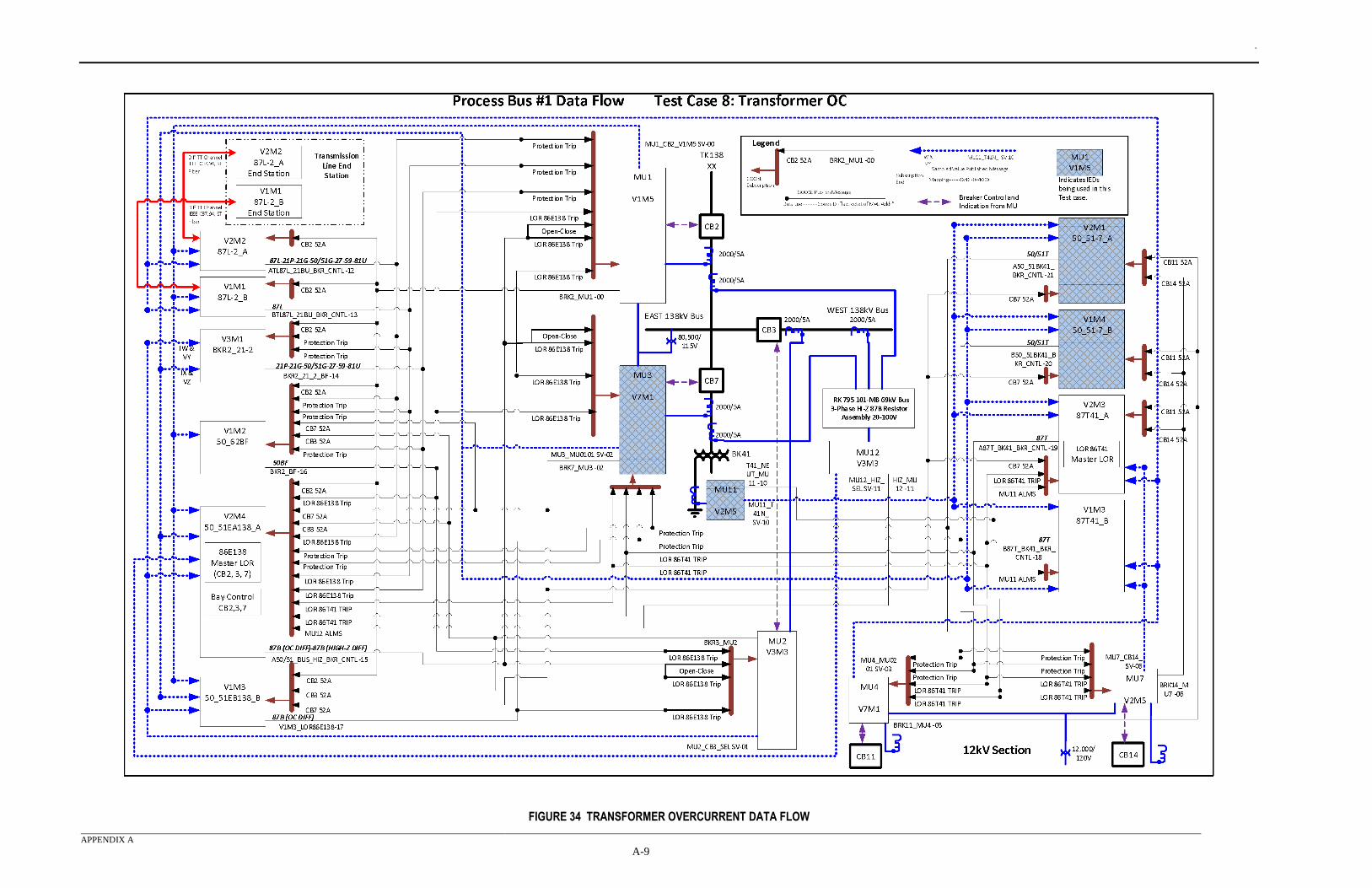
.
APPENDIX A
A-9
FIGURE 34 TRANSFORMER OVERCURRENT DATA FLOW
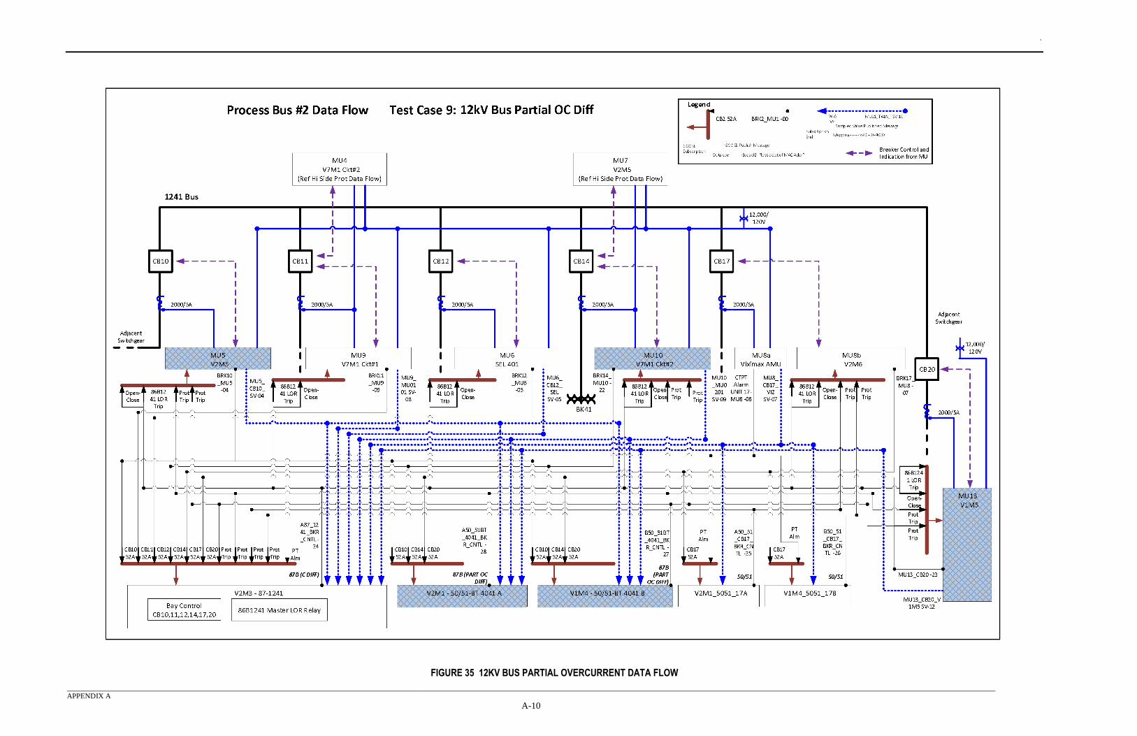
.
APPENDIX A
A-10
FIGURE 35 12KV BUS PARTIAL OVERCURRENT DATA FLOW
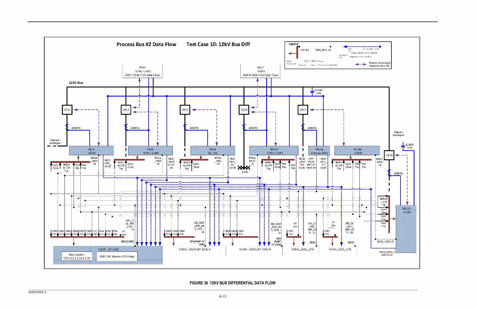
.
APPENDIX A
A-11
FIGURE 36 12KV BUS DIFFERENTIAL DATA FLOW
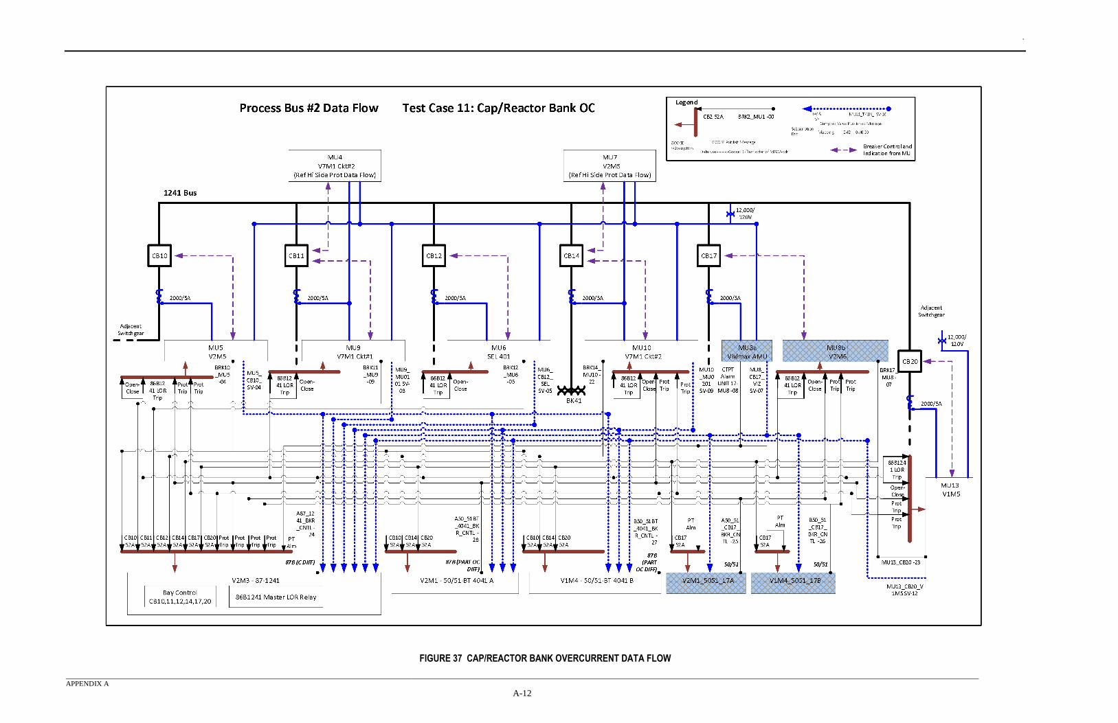
.
APPENDIX A
A-12
FIGURE 37 CAP/REACTOR BANK OVERCURRENT DATA FLOW
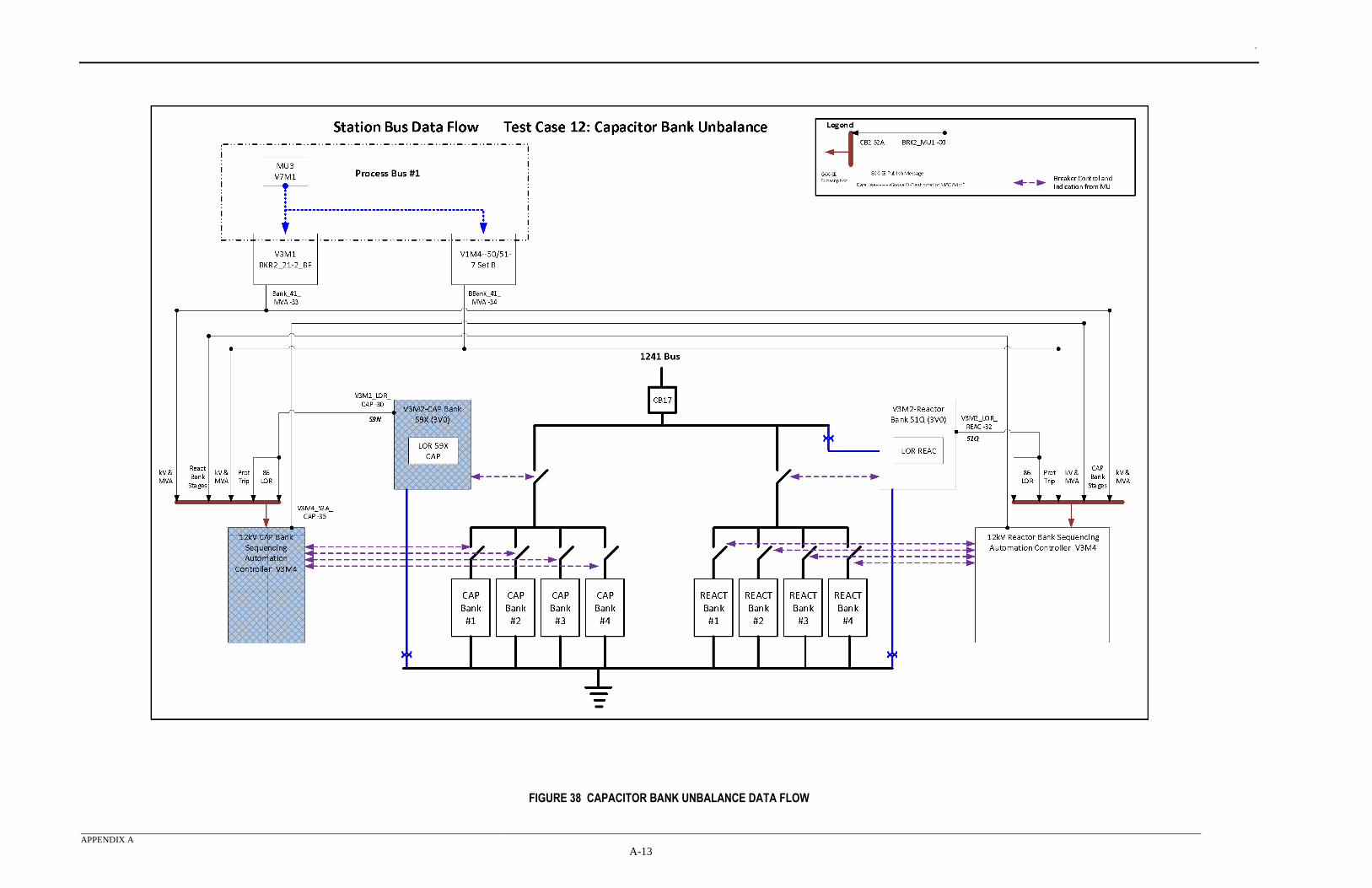
.
APPENDIX A
A-13
FIGURE 38 CAPACITOR BANK UNBALANCE DATA FLOW
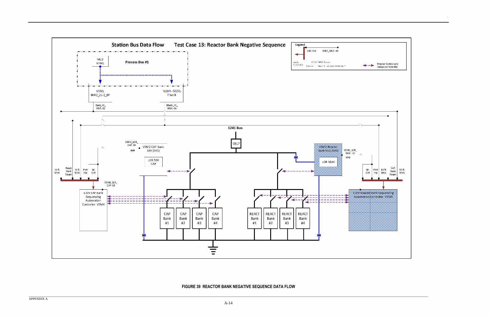
.
APPENDIX A
A-14
FIGURE 39 REACTOR BANK NEGATIVE SEQUENCE DATA FLOW
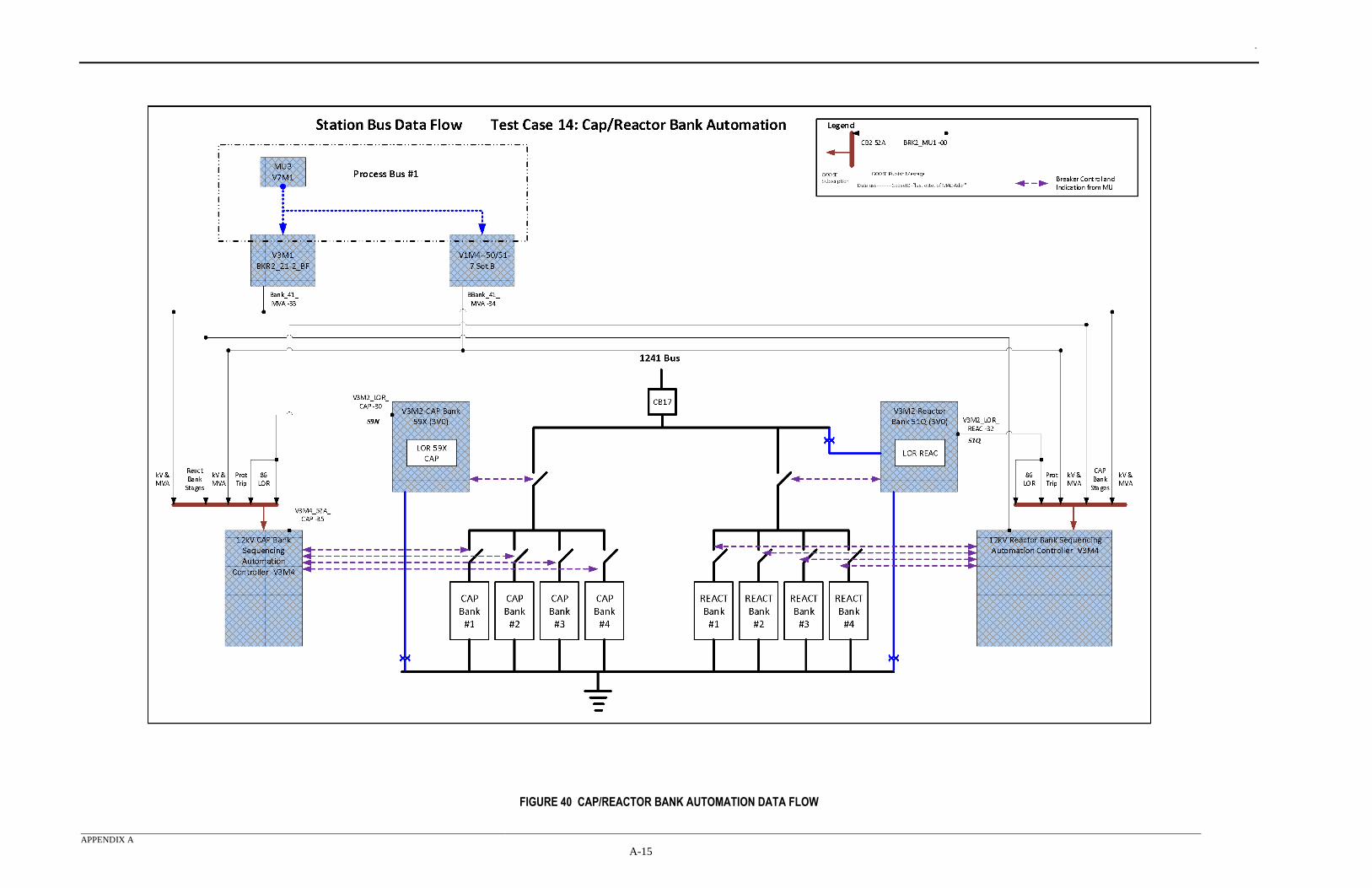
.
APPENDIX A
A-15
FIGURE 40 CAP/REACTOR BANK AUTOMATION DATA FLOW
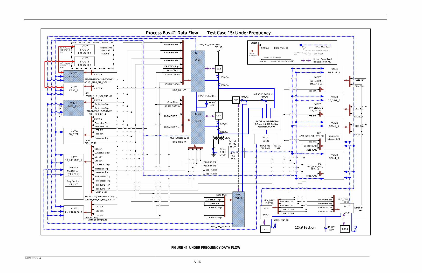
.
APPENDIX A
A-16
FIGURE 41 UNDER FREQUENCY DATA FLOW
.
APPENDIX B
B-1
APPENDIX B - RTDS MODEL DIAGRAM This Appendix B shows the full system model which was used in the RTDS to develop the test
parameters and characteristics for each use case. The model in Figure 42 includes all the breakers,
capacitors, reactors, transformers and transmission lines in the test system. This diagram also shows
the locations of each fault.
Figure 43 shows the RTDS interface. It allowed the display of the controls for each fault as well as
breaker status and test results.
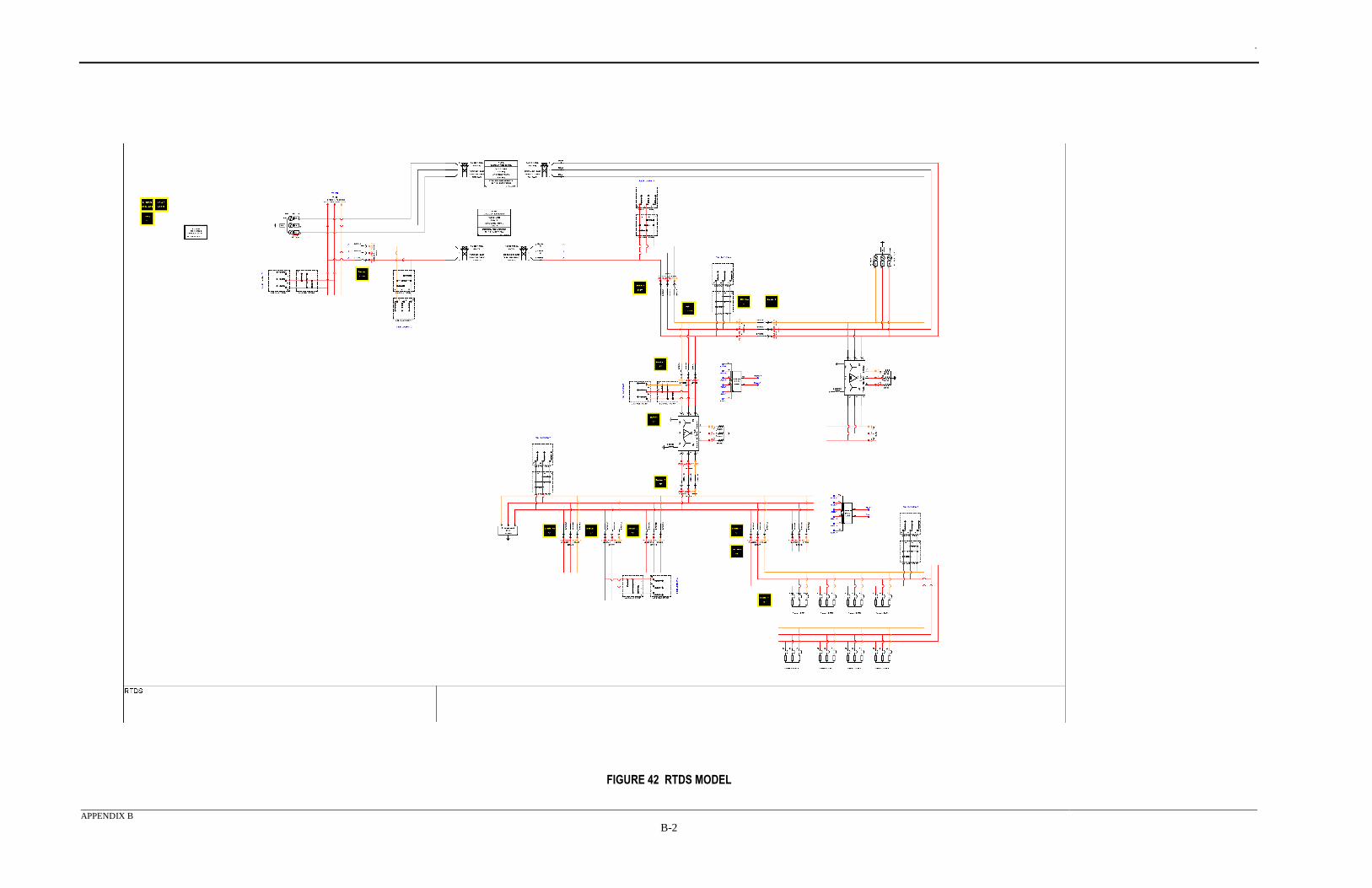
.
APPENDIX B
B-2
FIGURE 42 RTDS MODEL
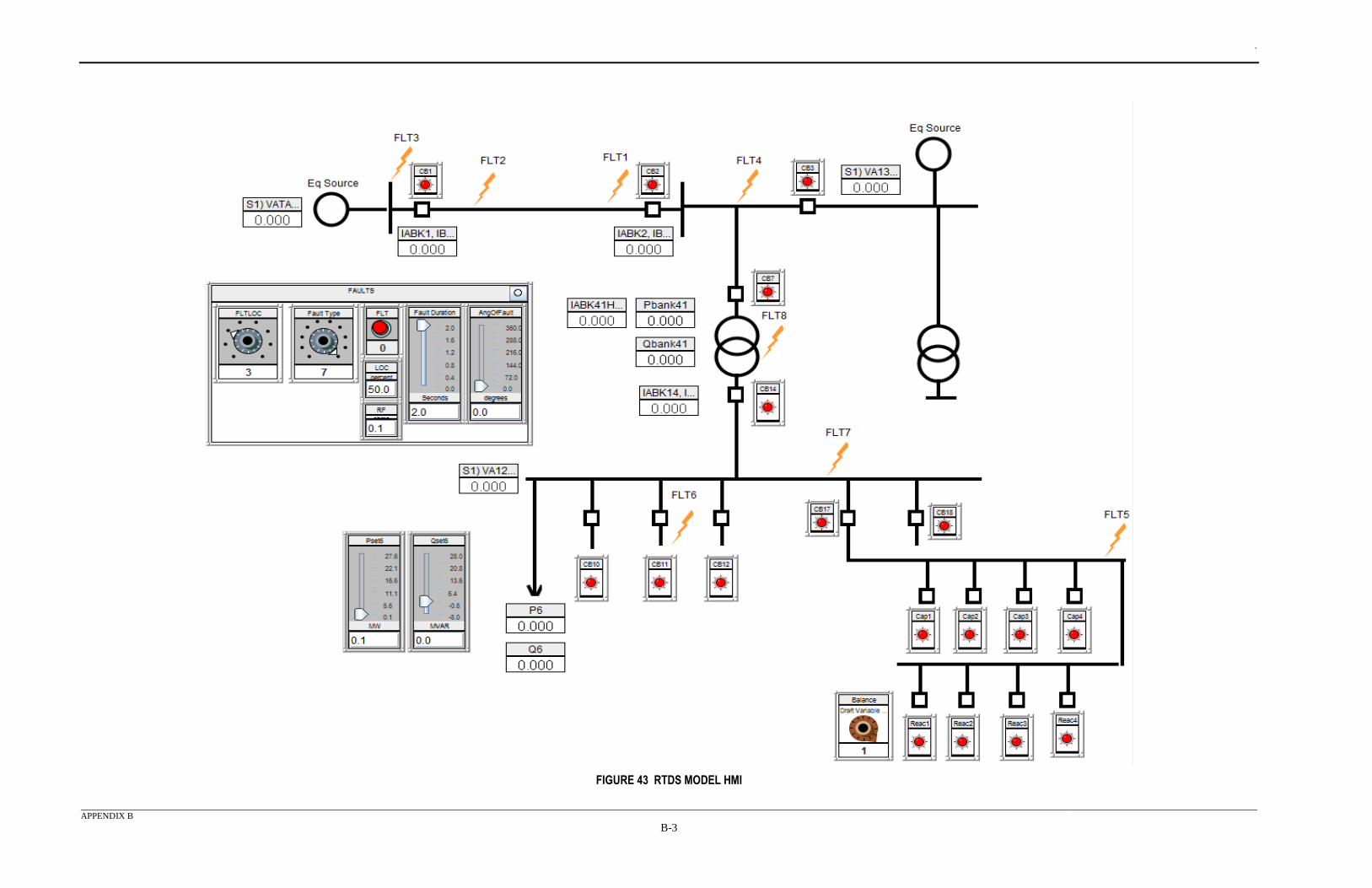
.
APPENDIX B
B-3
FIGURE 43 RTDS MODEL HMI
.
APPENDIX C
C-1
APPENDIX C - NETWORK LAYOUT DIAGRAM The network layout diagram identifies the network connections for each device included in the test
system. The diagram includes protection relays, merging units, Ethernet switches and the GPS time
clock. In this diagram, the isolated process bus and station bus connections are laid out. These
connections are indicated with colored lines to easily and quickly distinguish the networks. Blue
lines indicate station bus connections, green lines are bus #1 and red is for process bus #2. The
diagram indicates GPS time signals with yellow lines. Also shown in this diagram are the CT/PT
sensors and breakers associated with particular merging units. The diagram indicates the physical
separation of the substation control shelter and the substation yard with a thick dashed line near the
middle of the image.
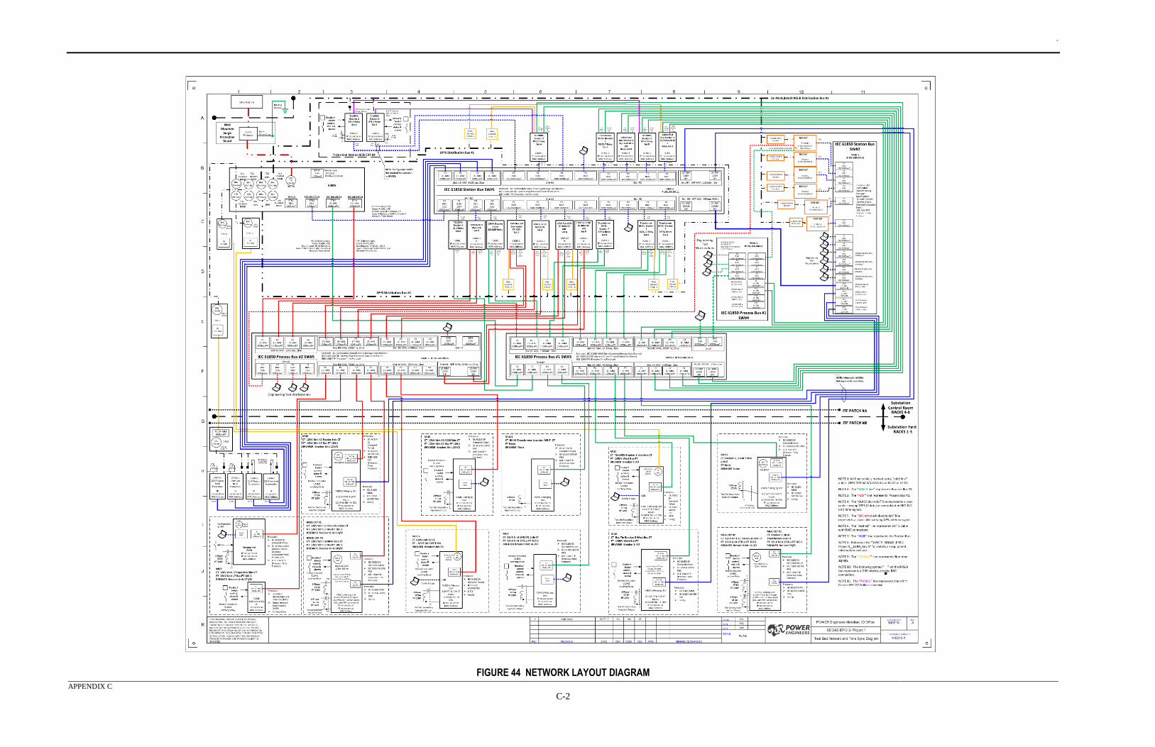
.
APPENDIX C
C-2
FIGURE 44 NETWORK LAYOUT DIAGRAM
.
APPENDIX D
D-1
APPENDIX D - IEC61850 MATRIX This appendix contains the IEC 61850 matrices. The matrix in Table 28 describes the IEDs which were
used in the HS and LS use cases. HS cases are indicated with red shading and LS with green shading.
This matrix was also used to explain the protection function nomenclature for each protection relay and
shows the relay identifiers. In any given row, the control and lock out functions are associated with the
relays in that row.
In Table 29, merging units are described with their functional position in the test system. HS cases are
indicated with red shading and LS with green shading.
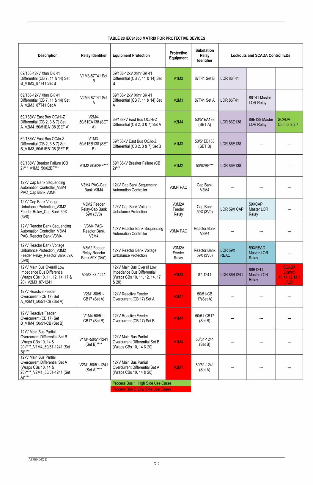
.
APPENDIX D
D-2
TABLE 28 IEC61850 MATRIX FOR PROTECTIVE DEVICES
Description Relay Identifier Equipment Protection Protective Equipment
Substation Relay
Identifier Lockouts and SCADA Control IEDs
69/138-12kV Xfmr BK 41 Differential (CB 7, 11 & 14) Set B_V1M3_87T41 Set B
V1M3-87T41 Set B
69/138-12kV Xfmr BK 41 Differential (CB 7, 11 & 14) Set B
V1M3 87T41 Set B LOR 86T41
69/138-12kV Xfmr BK 41 Differential (CB 7, 11 & 14) Set A_V2M3_87T41 Set A
V2M3-87T41 Set A
69/138-12kV Xfmr BK 41 Differential (CB 7, 11 & 14) Set A
V2M3 87T41 Set A LOR 86T41 86T41 Master LOR Relay
69/138kV East Bus OC/Hi-Z Differential (CB 2, 3 & 7) Set A_V2M4_50/51EA138 (SET A)
V2M4-50/51EA138 (SET
A)
69/138kV East Bus OC/Hi-Z Differential (CB 2, 3 & 7) Set A
V2M4 50/51EA138
(SET A) LOR 86E138
86E138 Master LOR Relay
SCADA Control 2,3,7
69/138kV East Bus OC/lo-Z Differential (CB 2, 3 & 7) Set B_V1M3_50/51EB138 (SET B)
V1M3-50/51EB138 (SET
B)
69/138kV East Bus OC/lo-Z Differential (CB 2, 3 & 7) Set B
V1M3 50/51EB138
(SET B) LOR 86E138 --- ---
69/138kV Breaker Failure (CB 2)***_V1M2_50/62BF***
V1M2-50/62BF*** 69/138kV Breaker Failure (CB 2)***
V1M2 50/62BF*** LOR 86E138 --- ---
12kV Cap Bank Sequencing Automation Controller_V3M4 PAC_Cap Bank V3M4
V3M4 PAC-Cap Bank V3M4
12kV Cap Bank Sequencing Automation Controller
V3M4 PAC Cap Bank
V3M4 --- --- ---
12kV Cap Bank Voltage Unbalance Protection_V3M2 Feeder Relay_Cap Bank 59X (3V0)
V3M2 Feeder Relay-Cap Bank
59X (3V0)
12kV Cap Bank Voltage Unbalance Protection
V3M2A Feeder Relay
Cap Bank 59X (3V0)
LOR 59X CAP 59XCAP Master LOR Relay
---
12kV Reactor Bank Sequencing Automation Controller_V3M4 PAC_Reactor Bank V3M4
V3M4 PAC-Reactor Bank
V3M4
12kV Reactor Bank Sequencing Automation Controller
V3M4 PAC Reactor Bank
V3M4 --- --- ---
12kV Reactor Bank Voltage Unbalance Protection_V3M2 Feeder Relay_Reactor Bank 59X (3V0)
V3M2 Feeder Relay-Reactor
Bank 59X (3V0)
12kV Reactor Bank Voltage Unbalance Protection
V3M2A Feeder Relay
Reactor Bank 59X (3V0)
LOR 59X REAC
59XREAC Master LOR Relay
---
12kV Main Bus Overall Low Impedance Bus Differential (Wraps CBs 10, 11, 12, 14, 17 & 20)_V2M3_87-1241
V2M3-87-1241
12kV Main Bus Overall Low Impedance Bus Differential (Wraps CBs 10, 11, 12, 14, 17 & 20)
V2M3 87-1241 LOR 86B1241 86B1241 Master LOR Relay
SCADA Control
10,11,12,14,17,20
12kV Reactive Feeder Overcurrent (CB 17) Set A_V2M1_50/51-CB (Set A)
V2M1-50/51-CB17 (Set A)
12kV Reactive Feeder Overcurrent (CB 17) Set A
V2M1 50/51-CB 17(Set A)
--- --- ---
12kV Reactive Feeder Overcurrent (CB 17) Set B_V1M4_50/51-CB (Set B)
V1M4-50/51-CB17 (Set B)
12kV Reactive Feeder Overcurrent (CB 17) Set B
V1M4 50/51-CB17
(Set B) --- --- ---
12kV Main Bus Partial Overcurrent Differential Set B (Wraps CBs 10, 14 & 20)****_V1M4_50/51-1241 (Set B)****
V1M4-50/51-1241 (Set B)****
12kV Main Bus Partial Overcurrent Differential Set B (Wraps CBs 10, 14 & 20)
V1M4 50/51-1241
(Set B) --- --- ---
12kV Main Bus Partial Overcurrent Differential Set A (Wraps CBs 10, 14 & 20)****_V2M1_50/51-1241 (Set A)****
V2M1-50/51-1241 (Set A)****
12kV Main Bus Partial Overcurrent Differential Set A (Wraps CBs 10, 14 & 20)
V2M1 50/51-1241
(Set A) --- --- ---
Process Bus 1 High Side Use Cases
Process Bus 2 Low Side Use Cases
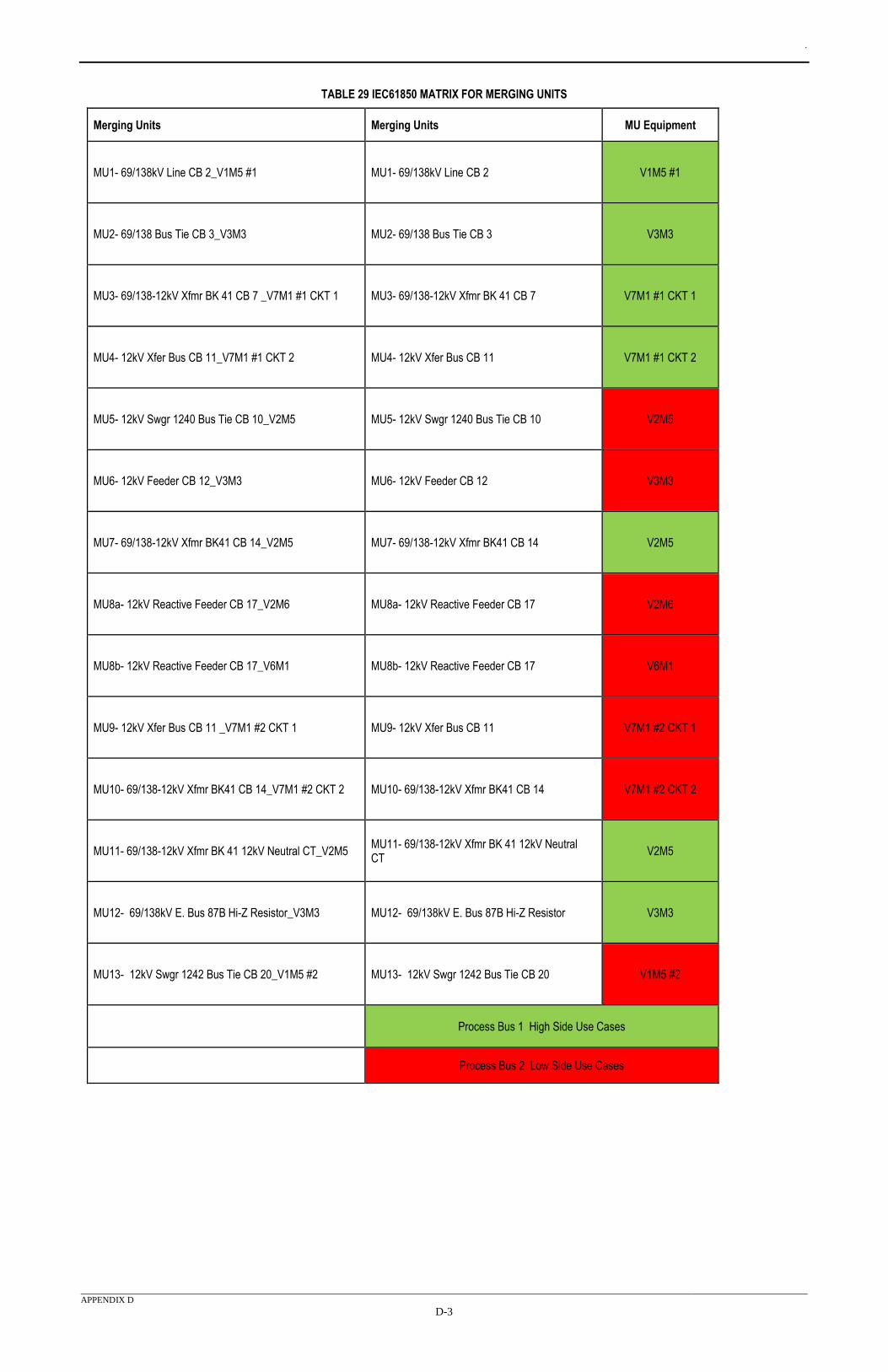
.
APPENDIX D
D-3
TABLE 29 IEC61850 MATRIX FOR MERGING UNITS
Merging Units Merging Units MU Equipment
MU1- 69/138kV Line CB 2_V1M5 #1 MU1- 69/138kV Line CB 2 V1M5 #1
MU2- 69/138 Bus Tie CB 3_V3M3 MU2- 69/138 Bus Tie CB 3 V3M3
MU3- 69/138-12kV Xfmr BK 41 CB 7 _V7M1 #1 CKT 1 MU3- 69/138-12kV Xfmr BK 41 CB 7 V7M1 #1 CKT 1
MU4- 12kV Xfer Bus CB 11_V7M1 #1 CKT 2 MU4- 12kV Xfer Bus CB 11 V7M1 #1 CKT 2
MU5- 12kV Swgr 1240 Bus Tie CB 10_V2M5 MU5- 12kV Swgr 1240 Bus Tie CB 10 V2M5
MU6- 12kV Feeder CB 12_V3M3 MU6- 12kV Feeder CB 12 V3M3
MU7- 69/138-12kV Xfmr BK41 CB 14_V2M5 MU7- 69/138-12kV Xfmr BK41 CB 14 V2M5
MU8a- 12kV Reactive Feeder CB 17_V2M6 MU8a- 12kV Reactive Feeder CB 17 V2M6
MU8b- 12kV Reactive Feeder CB 17_V6M1 MU8b- 12kV Reactive Feeder CB 17 V6M1
MU9- 12kV Xfer Bus CB 11 _V7M1 #2 CKT 1 MU9- 12kV Xfer Bus CB 11 V7M1 #2 CKT 1
MU10- 69/138-12kV Xfmr BK41 CB 14_V7M1 #2 CKT 2 MU10- 69/138-12kV Xfmr BK41 CB 14 V7M1 #2 CKT 2
MU11- 69/138-12kV Xfmr BK 41 12kV Neutral CT_V2M5 MU11- 69/138-12kV Xfmr BK 41 12kV Neutral CT
V2M5
MU12- 69/138kV E. Bus 87B Hi-Z Resistor_V3M3 MU12- 69/138kV E. Bus 87B Hi-Z Resistor V3M3
MU13- 12kV Swgr 1242 Bus Tie CB 20_V1M5 #2 MU13- 12kV Swgr 1242 Bus Tie CB 20 V1M5 #2
Process Bus 1 High Side Use Cases
Process Bus 2 Low Side Use Cases
.
APPENDIX E
E-1
APPENDIX E - IEC61850 DATA FLOW SPREADSHEETS Appendix E contains the IEC61850 dataflow spreadsheets. Analogous to a wiring schematic, this
spreadsheet details each message being used in the test system. Because the messages could become
numerous and unwieldy, the spreadsheet is necessarily large. For each network bus, the spreadsheet
is divided into two sections; one for SV messages and one for GOOSE messages. Publishing IEDs
are listed along the far left column, and subscribing IEDs are listed along the top. Details of each
message are listed in the middle.
This spreadsheet provides details about each IED, such as system functional position, CT/PT ratios,
measurement and control points. SV and GOOSE control blocks are detailed with the broadcast
MAC address, VLAN ID, VLAN priority, Application ID (APP ID) and message ID. Each index of
the message is then detailed moving across the spreadsheet from left to right. The IEC 61850
standard defines sampled values message structure, and as such, these messages were identical.
GOOSE messages were configured specifically for their individual purpose. Logic nodes, logical
devices, data objects and data attributes are all defined in this spreadsheet. In the subscribing IEDs
section of the spreadsheet, to the far right, subscribers to certain messages are indicated by a ‘Yes’ in
the cell. If a device is not subscribing to a message, that cell was grayed out. The data flow tables are
further described in Section 9.
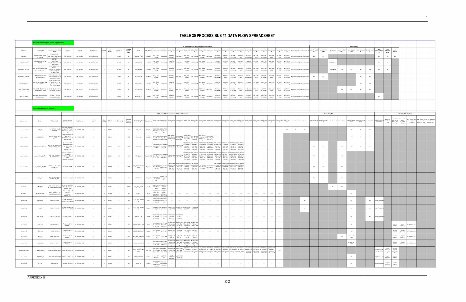
.
APPENDIX E
E-2
TABLE 30 PROCESS BUS #1 DATA FLOW SPREADSHEET
IEDname Publishing IEDMeasurement and Control
pointsVoltage Current MAC Address VLAN ID
VLAN-
PRIORITYApp ID (hex)
SmpRate
(sample/
cycle)
MsvID Dataset NameDataset index
1
Dataset index
2
Dataset index
3
Dataset index
4
Dataset index
5
Dataset index
6
Dataset index
7
Dataset index
8
Dataset index
9
Dataset index
10
Dataset index
11
Dataset index
12
Dataset index
13
Dataset index
14
Dataset index
15
Dataset index
16
Dataset index
14
Dataset index
15Dataset index 16 Dataset index 16
V2M2**--87L-2
Set A
V1M1**--87L-2
Set BV3M1--21-2
V2M1--50/51-7
Set A
V1M4--50/51-7
Set B
V1M3--87T41 Set
B
V2M3--87T41 Set
A
V2M4-
50/51EA138 (SET
A)
V1M3--
50/51EB138
(SET B)
V1M2--
50/62BF
MU1_CB2MU1- 69/138kV Line CB
2_V1M5 #1
69/138kV Line CB 2
Line Side CT, west bud PT
and CB2 I/O
115V - 700 ratio 5A - 400 ratio 01-0C-CD-04-00-00 1 4 0x4000 80 MU1_CB2_V1M5 PhsMeas1PhA_Amps.
instMag.i PhA_Amps.q
PhB_Amps.
instMag.i PhB_Amps.q
PhC_Amps.
instMag.i PhC_Amps.q
NEUT Amps.
instMag.i NEUT Amps. q
PhA Volts-
Vol.instMag.i
PhA Volts-
Vol.q
PhB Volts-
Vol.instMag.i
PhB Volts-
Vol.q
PhC Volts-
Vol.instMag.i
PhC Volts-
Vol.q
NEUT Volts-
Vol.instMag.i
NEUT Volts-
Vol.q
PhC Volts-
Vol.q
NEUT Volts-
Vol.instMag.iNEUT Volts-Vol.q NEUT Volts-Vol.q YES YES YES YES YES
MU2_CB3_V3M3MU2- 69/138 Bus Tie CB
3_V3M3
69/138kV
Bus Tie CB 3
West Bus CT, west bus PT
and CB3 I/O
115V - 700 ratio 5A - 400 ratio 01-0C-CD-04-00-01 1 4 0x4000 80 MU2_CB3_V3 PhsMeas1PhA_Amps.
instMag.i PhA_Amps.q
PhB_Amps.
instMag.i PhB_Amps.q
PhC_Amps.
instMag.i PhC_Amps.q
NEUT Amps.
instMag.i NEUT Amps. q
PhA Volts-
Vol.instMag.i
PhA Volts-
Vol.q
PhB Volts-
Vol.instMag.i
PhB Volts-
Vol.q
PhC Volts-
Vol.instMag.i
PhC Volts-
Vol.q
NEUT Volts-
Vol.instMag.i
NEUT Volts-
Vol.q
PhC Volts-
Vol.q
NEUT Volts-
Vol.instMag.iNEUT Volts-Vol.q NEUT Volts-Vol.q YES (IW & VY) YES YES
MU3_4_CB7_11_V7M1MU3- 69/138-12kV Xfmr BK 41
CB 7 _V7M1 #1 CKT 1
69/138-12kV Xfmr BK 41
Main CB 7
Xfmr Side CT, 12kV Swgr
1241 Unit 17 Bus PT
100:1and CB7 I/O
115V - 700 ratio 5A - 400 ratio 01-0C-CD-04-00-02 1 4 0x4000 80 MU3_MU0101 PhsMeas1PhA_Amps.
instMag.i PhA_Amps.q
PhB_Amps.
instMag.i PhB_Amps.q
PhC_Amps.
instMag.i PhC_Amps.q
NEUT Amps.
instMag.i NEUT Amps. q
PhA Volts-
Vol.instMag.i
PhA Volts-
Vol.q
PhB Volts-
Vol.instMag.i
PhB Volts-
Vol.q
PhC Volts-
Vol.instMag.i
PhC Volts-
Vol.q
NEUT Volts-
Vol.instMag.i
NEUT Volts-
Vol.q
PhC Volts-
Vol.q
NEUT Volts-
Vol.instMag.iNEUT Volts-Vol.q NEUT Volts-Vol.q YES (IX & VZ) YES YES YES YES YES YES
MU3_4_CB7_11_V7M1MU4- 12kV Xfer Bus CB
11_V7M1 #1 CKT 2
12kV Xfer Bus CB 11, 12kV
Swgr 1241 Unit 17 Bus PT
100:1, CB Unit 11 I/O
120V - 100 ratio 5A - 400 ratio 01-0C-CD-04-00-03 1 4 0x4000 80 MU4_MU0201 PhsMeas1PhA_Amps.
instMag.i PhA_Amps.q
PhB_Amps.
instMag.i PhB_Amps.q
PhC_Amps.
instMag.i PhC_Amps.q
NEUT Amps.
instMag.i NEUT Amps. q
PhA Volts-
Vol.instMag.i
PhA Volts-
Vol.q
PhB Volts-
Vol.instMag.i
PhB Volts-
Vol.q
PhC Volts-
Vol.instMag.i
PhC Volts-
Vol.q
NEUT Volts-
Vol.instMag.i
NEUT Volts-
Vol.q
PhC Volts-
Vol.q
NEUT Volts-
Vol.instMag.iNEUT Volts-Vol.q NEUT Volts-Vol.q YES YES YES YES
MU7_CB14_V2M5MU7- 69/138-12kV Xfmr BK41
CB 14_V2M5
69/138-12kV Xfmr BK41
CB 14 Xfmr Side CT, 2kV
Swgr 1241 Unit 17 Bus PT
100:1, CB Unit 14 I/O
115V - 700 ratio 5A - 400 ratio 01-0C-CD-04-00-06 1 4 0x4000 80 MU7_CB14_V2 PhsMeas1PhA_Amps.
instMag.i PhA_Amps.q
PhB_Amps.
instMag.i PhB_Amps.q
PhC_Amps.
instMag.i PhC_Amps.q
NEUT Amps.
instMag.i NEUT Amps. q
PhA Volts-
Vol.instMag.i
PhA Volts-
Vol.q
PhB Volts-
Vol.instMag.i
PhB Volts-
Vol.q
PhC Volts-
Vol.instMag.i
PhC Volts-
Vol.q
NEUT Volts-
Vol.instMag.i
NEUT Volts-
Vol.q
PhC Volts-
Vol.q
NEUT Volts-
Vol.instMag.iNEUT Volts-Vol.q NEUT Volts-Vol.q YES YES
MU11_T41NEU_V2M5MU11- 69/138-12kV Xfmr BK 41
12kV Neutral CT_V2M5
69/138-12kV Xfmr BK 41
12kV Neutral CT, no I/O120V - 100 ratio 5A - 400 ratio 01-0C-CD-04-00-10 1 4 0x4000 80 MU11_T41N_V2 PhsMeas1
PhA_Amps.
instMag.i PhA_Amps.q
PhB_Amps.
instMag.i PhB_Amps.q
PhC_Amps.
instMag.i PhC_Amps.q
NEUT Amps.
instMag.i NEUT Amps. q
PhA Volts-
Vol.instMag.i
PhA Volts-
Vol.q
PhB Volts-
Vol.instMag.i
PhB Volts-
Vol.q
PhC Volts-
Vol.instMag.i
PhC Volts-
Vol.q
NEUT Volts-
Vol.instMag.i
NEUT Volts-
Vol.q
PhC Volts-
Vol.q
NEUT Volts-
Vol.instMag.iNEUT Volts-Vol.q NEUT Volts-Vol.q YES YES YES YES
MU12_HIZ_V3M3MU12- 69/138kV E. Bus 87B Hi-
Z Resistor_V3M3
69/138kV E. Bus 87B
Hi-Z Resistor, no I/O115V - 700 ratio 5A - 400 ratio 01-0C-CD-04-00-11 1 4 0x4000 80 MU12_HIZ_V3 PhsMeas1
PhA_Amps.
instMag.i PhA_Amps.q
PhB_Amps.
instMag.i PhB_Amps.q
PhC_Amps.
instMag.i PhC_Amps.q
NEUT Amps.
instMag.i NEUT Amps. q
PhA Volts-
Vol.instMag.i
PhA Volts-
Vol.q
PhB Volts-
Vol.instMag.i
PhB Volts-
Vol.q
PhC Volts-
Vol.instMag.i
PhC Volts-
Vol.q
NEUT Volts-
Vol.instMag.i
NEUT Volts-
Vol.q
PhC Volts-
Vol.q
NEUT Volts-
Vol.instMag.iNEUT Volts-Vol.q NEUT Volts-Vol.q YES
Summary Use IEDname Publishing IEDMeasurement and
Control points, etc.MAC Address VLAN ID
VLAN-
PRIORITY
App ID
(hex)Min Trime (ms)
Heatbeat
Rate, Max
time (ms)
Control Block Name
and GoIDDataset Name
Dataset index
1
Dataset index
2
Dataset index
3
Dataset index
4
Dataset index
5
Dataset index
6
Dataset index
7
Dataset index
8
Dataset index
9
Dataset index
10
Dataset index
11
Dataset index
12
Dataset index
13
Dataset index
14
Dataset index
15
Dataset index
16
Dataset index
17
V2M2**--87L-2
Set AV1M1**--87L-2 Set B V3M1--21-2
V2M1--50/51-7 Set
A
V1M4--50/51-7 Set
BV1M3--87T41 Set B V2M3--87T41 Set A
V2M4-50/51EA138
(SET A)
V1M3--50/51EB138
(SET B)V1M2--50/62BF
MU1- 69/138kV Line
CB 2_V1M5 #1
MU2- 69/138
Bus Tie CB
3_V3M3
MU3- 69/138-
12kV Xfmr BK
41 CB 7 _V7M1
#1 CKT 1
MU4- 12kV Xfer
Bus CB
11_V7M1 #1
CKT 2
MU7- 69/138-12kV
Xfmr BK41 CB
14_V2M5
MU11- 69/138-12kV
Xfmr BK 41 12kV
Neutral CT_ V2M5
MU12- 69/138kV E.
Bus 87B Hi-Z
Resistor_V3M3
Breaker Position MU1_CB2MU1- 69/138kV Line CB
2_V1M5 #1
CT TL138XX Breaker 2
Line Side CT; PT 138kV
West Bus PT; Breaker 2
I/O
01-0C-CD-01-00-00 1 4 0x0000 4 500 BRK2_MU1 CB2_52A
GGIO1.SPCS01.
stVal (Input 1-
52a)
GGIO1.SPCS01.
q (Input 1-
52a)
----- ----- ----- ----- ----- ----- ----- ----- ----- ----- ----- ----- ----- ----- ----- YES YES YES YES YES YES
Breaker Position MU2_CB3_V3M3MU2- 69/138 Bus Tie CB
3_V3M3
CT Bus Tie Breaker 3
West Bus CT
PT 138kV West Bus PT
BREAKER 3 I/O
01-0C-CD-01-00-01 1 4 0x0001 4 1000 BRK3_MU2 CB3_52A
ANN.IN2GGIO
14,Ind01.stVal
(Input 1- 52a)
ANN.IN2GGIO
14,Ind01.q
(Input 1- 52a)
ANN.IN2GGIO
14,Ind02.stVal
(VT Fuse Fail
A)
ANN.IN2GGIO
14,Ind02.q (VT
Fuse Fail A)
ANN.IN2GGIO
14,Ind03.stVal
(VT Fuse Fail
B)
ANN.IN2GGIO
14,Ind03.q (VT
Fuse Fail B)
ANN.IN2GGIO
14,Ind04.stVal
(VT Fuse Fail
C)
ANN.IN2GGIO
14,Ind04.q (VT
Fuse Fail C)
----- ----- ----- ----- ----- ----- ----- ----- ----- YES YES YES
Breaker Position MU3_MU4 CB7_11_V7M1MU3- 69/138-12kV Xfmr BK
41 CB 7 _V7M1 #1 CKT 1
CT Breaker 7 BK 41
Transformer Side CT
PT 12kV Unit 17 Bus PT
100:1
BREAKER 7 I/O
01-0C-CD-01-00-02 1 4 0x0002 20 1000 BRK7_MU3 MU3_STATUS
CTRL/BININGG
IO1.Ind1.stVal
(CB7 52A)
CTRL/BININGG
IO1.Ind1.q
(CB7 52A)
CTRL/BININGG
IO1.Ind2.stVal
CTRL/BININGG
IO1.Ind2.q
CTRL/BININGG
IO1.Ind3.stVal
(CB7 1241
UNIT 17 PT
PHA FUSE)
CTRL/BININGG
IO1.Ind3.q
(CB7 1241
UNIT 17 PT
PHA FUSE)
CTRL/BININGG
IO1.Ind4.stVal
(CB7 1241
UNIT 17 PT
PHB FUSE)
CTRL/BININGG
IO1.Ind4.q
(CB7 1241
UNIT 17 PT
PHB FUSE)
CTRL/BININGG
IO1.Ind5.stVal
(CB7 1241
UNIT 17 PT
PHC FUSE)
CTRL/BININGG
IO1.Ind5.q
(CB7 1241
UNIT 17 PT
PHC FUSE)
CTRL/BININGG
IO1.Ind6stVal
(CB7 1241
UNIT 17 PT
NEU FUSE)
CTRL/BININGG
IO1.Ind6.q
(CB7 1241
UNIT 17 PT
NEU FUSE)
----- ----- ----- ----- ----- YES YES YES YES YES YES
Breaker Position MU3_MU4 CB7_11_V7M1MU4- 12kV Xfer Bus CB
11_V7M1 #1 CKT 2
CT 12kV Unit 11 Trans
Bus Side CT
PT 12kV Unit 17 Bus PT
100:1
BREAKER Unit 11 I/O
01-0C-CD-01-00-03 1 4 0x0003 20 500 BRK11_MU4 MU4_STATUS
CTRL/BININGG
IO1.Ind7.stVal
(CB11 52A)
CTRL/BININGG
IO1.Ind7.q
(CB11 52A)
CTRL/BININGG
IO1.Ind8.stVal
CTRL/BININGG
IO1.Ind8.q
CTRL/BININGG
IO1.Ind9stVal
(CB11 1241
UNIT 17 PT
PHA FUSE)
CTRL/BININGG
IO1.Ind9.q
(CB11 1241
UNIT 11 PT
PHA FUSE)
CTRL/BININGG
IO1.Ind10.stVa
l (CB11 1241
UNIT 11 PT
PHB FUSE)
CTRL/BININGG
IO1.Ind10.q
(CB11 1241
UNIT 11 PT
PHB FUSE)
CTRL/BININGG
IO1.Ind11.stVa
l (CB11 1241
UNIT 11 PT
PHC FUSE)
CTRL/BININGG
IO1.Ind11.q
(CB11 1241
UNIT 11 PT
PHC FUSE)
CTRL/BININGG
IO1.Ind12stVal
(CB11 1241
UNIT 11 PT
NEU FUSE)
CTRL/BININGG
IO1.Ind12.q
(CB11 1241
UNIT 11 PT
PNEU FUSE)
----- ----- ----- ----- ----- YES YES YES
Breaker Position MU3_MU4 CB7_11_V7M1MU3 & MU4 CB7 & CB 11-
1_V7M1 #1&2 ALL STATUS INPUTS 01-0C-CD-01-00-39 1 4 0x0027 1 1000
MU3_MU4_FASTGOOSE
_FIXEDDigInput
CTRL/BININGG
IO1.Ind1.stVal
(CB7 52A)
CTRL/BININGG
IO1.Ind2.stVal
CTRL/BININGG
IO1.Ind3.stVal
(CB7 1241
UNIT 17 PT
PHA FUSE)
CTRL/BININGG
IO1.Ind4.stVal
(CB7 1241
UNIT 17 PT
PHB FUSE)
CTRL/BININGG
IO1.Ind5.stVal
(CB7 1241
UNIT 17 PT
PHC FUSE)
CTRL/BININGG
IO1.Ind6stVal
(CB7 1241
UNIT 17 PT
NEU FUSE)
CTRL/BININGG
IO1.Ind7.stVal
(CB11 52A)
CTRL/BININGG
IO1.Ind8.stVal
CTRL/BININGG
IO1.Ind9stVal
(CB11 1241
UNIT 17 PT
PHA FUSE)
CTRL/BININGG
IO1.Ind10.stVa
l (CB11 1241
UNIT 11 PT
PHB FUSE)
CTRL/BININGG
IO1.Ind11.stVa
l (CB11 1241
UNIT 11 PT
PHC FUSE)
CTRL/BININGG
IO1.Ind12stVal
(CB11 1241
UNIT 11 PT
NEU FUSE)
----- ----- ----- ----- ----- YES YES YES
Breaker Position V2M5_MU7MU7- 69/138-12kV Xfmr
BK41 CB 14_V2M5BREAKER Unit 14 I/O 01-0C-CD-01-00-06 1 4 0x0006 4 500 BRK14_MU7 CB14_52A
MVGAPC1.Ind
1.stVal (CB 14
52A)
MVGAPC1.Ind
1.q (CB 14
52A)
----- ----- ----- ----- ----- ----- ----- ----- ----- ----- ----- ----- ----- ----- ----- YES YES YES
MU Alarms V2M5_MU11MU11- 69/138-12kV Xfmr
41 12kV Neutral CT_V2M5
CT BK 41 Transformer
Low side NEUT CT
BREAKER None
01-0C-CD-01-00-10 1 4 0x000A 4 10000 T41_NEUT_MU11 ALARM
LLN0.Health.st
Val (internal
alarm)
LLN0.Health.q
(internal
alarm)
----- ----- ----- ----- ----- ----- ----- ----- ----- ----- ----- ----- ----- ----- ----- YES YES
MU Alarms MU12_HIZ_V3M3MU12- 69/138kV E. Bus
87B Hi-Z Resistor_V3M3
CT Breaker 2, 3 and 7
into a Hi-Z
PT None
BREAKER None
01-0C-CD-01-00-11 1 4 0x000B 4 500 HIZ_MU12 HIZ_AL
ANN.PLTGGIO
2.Ind01.stVal
(alarm point,
PB1 toggles)
ANN.PLTGGIO
2.Ind01.q
(Alarm point,
PB1 toggles)
----- ----- ----- ----- ----- ----- ----- ----- ----- ----- ----- ----- ----- ----- ----- YES
Breaker Trip V2M1_87L2A V2M2-87L-2 Set ATL138XX- Breaker 2 (2
each with line end IEDs)01-0C-CD-01-00-12 1 4 0x000C 4 500
ATL87L_21BU_BKR_CNT
LTRIP
CTRL/SMPPTR
C1.Op.general
(Trip CB 2)
CTRL/SMPPTR
C1.Op.q (Trip
CB 2)
----- ----- ----- ----- ----- ----- ----- ----- ----- ----- ----- ----- ----- ----- ----- YES YES YES YES (TRIP Output #1)
Breaker Trip 87L2B V1M1-87L-2 Set BTL138XX- Breaker 2 (2
each with line end IEDs)01-0C-CD-01-00-13 1 4 0x000D 4 500
BTL87L_21BU_BKR_CNT
LDataSet
LPHD0.SPS1.st
Val (Trip CB 2)
LPHD0.SPS1.q
(Trip CB 2)
LPHD0.SPS2.st
Val (FUTURE)
LPHD0.SPS2.q
(FUTURE)
LPHD0.SPS.stV
al (FUTURE)
LPHD0.SPS.q
(FUTURE) ----- ----- ----- ----- ----- ----- ----- ----- ----- ----- ----- YES YES YES YES (TRIP Output #1)
Breaker Trip BKR2_21-2_BF V3M1--21-2 &BF CB2 TL138XX- Breaker 2 01-0C-CD-01-00-14 1 4 0x000E 4 500 BKR2_21_2_BF TRIP_BF
PRO.TRIPPTRC
1.Tr.general
(21 Trip CB 2)
PRO.TRIPPTRC
1.Tr.q (21 Trip
CB 2)
PRO.BFR1RBRF
1.OpIn.q
(FUTURE)
PRO.BFR1RBRF
1.OpIn.t
(FUTURE)
----- ----- ----- ----- ----- ----- ----- ----- ----- ----- ----- ----- ----- YES YES YES (TRIP Output #1)
Breaker Trip 50_51-7_A V2M1-50/51-7 Set ATransformer BK 41-
Breaker 701-0C-CD-01-00-21 1 4 0x0015 4 500 A50_51BK41_BKR_CNTL TRIP
MON/SP16GA
PC1.Ind1.stVal
(Trip CB 7)
MON/SP16GA
PC1.Ind1.q
(Trip CB 7)
MON/SP16GA
PC1.Ind2.stVal
(Trip CB Unit
11)
MON/SP16GA
PC1.Ind2.q
(Trip CB Unit
11)
MON/SP16GA
PC1.Ind3.stVal
(Trip CB Unit
14)
MON/SP16GA
PC1.Ind3.q
(Trip CB Unit
14)
----- ----- ----- ----- ----- ----- ----- ----- ----- ----- ----- YESYES (TRIP
Output #1)
YES (TRIP
Output #1)YES (TRIP Output #1)
Breaker Trip 50_51-7_B V1M4-50/51-7 Set BTransformer BK 41-
Breaker 701-0C-CD-01-00-20 1 4 0x0014 4 500 B50_51BK41_BKR_CNTL DataSet
.stVal (Trip CB
7).q (Trip CB 7)
.stVal (Trip CB
Unit 11)
.q (Trip CB
Unit 11)
.stVal (Trip CB
Unit 14)
.q (Trip CB
Unit 14) ----- ----- ----- ----- ----- ----- ----- ----- ----- ----- ----- YES
YES (TRIP
Output #1)
YES (TRIP
Output #1)YES (TRIP Output #1)
Breaker Trip 87T41_B V1M3-87T41 Set BTransformer BK 41-
Breaker 701-0C-CD-01-00-18 1 4 0x0012 4 500 B87T_BK41_BKR_CNTL DataSet
.stVal (Trip CB
7).q (Trip CB 7)
.stVal (Trip CB
Unit 11)
.q (Trip CB
Unit 11)
.stVal (Trip CB
Unit 14)
.q (Trip CB
Unit 14) ----- ----- ----- ----- ----- ----- ----- ----- ----- ----- ----- YES
YES (Block CB7
Close)
YES (TRIP
Output #1)
YES (TRIP
Output #1)YES (TRIP Output #1)
Breaker Trip V2M3_87T41A V2M3-87T41 Set ATransformer BK 41-
Breaker 701-0C-CD-01-00-19 1 4 0x0013 4 500 A87T_BK41_BKR_CNTL TRIP
MON/SP16GA
PC1.Ind1.stVal
(Trip CB 7)
MON/SP16GA
PC1.Ind1.q
(Trip CB 7)
MON/SP16GA
PC1.Ind2.stVal
(Trip CB Unit
11)
MON/SP16GA
PC1.Ind2.q
(Trip CB Unit
11)
MON/SP16GA
PC1.Ind3.stVal
(Trip CB Unit
14)
MON/SP16GA
PC1.Ind3.q
(Trip CB Unit
14)
----- ----- ----- ----- ----- ----- ----- ----- ----- ----- -----YES (Block CB7
Close)
YES (TRIP
Output #1)
YES (TRIP
Output #1)YES (TRIP Output #1)
Breaker Trip - Close V2M4_5051EA138 V2M4-50/51EA138 (SET A) 138/69 Bus OC/Hi-Z Diff 01-0C-CD-01-00-15 1 4 0x000F 4 500A50/51_BUS_HIZ_BKR_
CNTLTRIP_CLS
MON/SP16GA
PC1.Ind1.stVal
(Open CB 2)
MON/SP16GA
PC1.Ind1.q
(Open CB 2)
MON/SP16GA
PC1.Ind2.stVal
(Close CB 2)
MON/SP16GA
PC1.Ind2.q
(Close CB 2)
MON/SP16GA
PC1.Ind3.stVal
(Open CB Unit
7)
MON/SP16GA
PC1.Ind3.q
(Open CB Unit
7)
MON/SP16GA
PC1.Ind4.stVal
(Close CB Unit
7)
MON/SP16GA
PC1.Ind4.q
(Close CB Unit
7)
MON/SP16GA
PC1.Ind5.stVal
(Open CB Unit
3)
MON/SP16GA
PC1.Ind5.q
(Open CB Unit
3)
MON/SP16GA
PC1.Ind6.stVal
(Close CB Unit
3)
MON/SP16GA
PC1.Ind6.q
(Close CB Unit
3)
MON/SP16GA
PC1.Ind7.stVal
(LOR86E138
Trip 2,3,7)
MON/SP16GA
PC1.Ind7.q
(LOR86E138
Trip 2,3,7)
MON/SP16GA
PC1.Ind8.stVal
(LOR86E138
Trip 2,3,7)#2
MON/SP16GA
PC1.Ind8.q
(LOR86E138
Trip 2,3,7) #2
-----YES (TRIP Output #1,
Close Output #2)
YES (TRIP
Output #1,
Close Output
#2)
YES (TRIP
Output #1,
Close Output
#2)
Breaker Trip 50_51EB138_B V1M3--50/51EB138 (SET B) 138/69 Bus OC/lo-Z Diff 01-0C-CD-01-00-17 1 4 0x0011 4 500 V1M3_LOR86E138 DataSet.stVal (CB3
Pro Trip)
.q ((CB3 Pro
Trip)
.stVal
(LOR86E138
Trip 2,3,7)
.q (LOR86E138
Trip 2,3,7) ----- ----- ----- ----- ----- ----- ----- ----- ----- ----- ----- ----- ----- YES YES (TRIP Output #1)
YES (TRIP
Output #1)
YES (TRIP
Output #1)
Breaker Trip 50_62BF V1M2-50/62BF TL138XX- Breaker 2 01-0C-CD-01-00-16 1 4 0x0010 4 500 BKR2__BF DataSet
RBRF1.OpEx.g
eneral
(LOR86E138 BF
Trip 2,3,7)
RBRF1.OpEx.q
(LOR86E138 BF
Trip 2,3,7)
---- ---- ---- ---- ---- ---- ---- ---- ---- ---- ---- ---- ---- ---- ---- YES YES (TRIP Output #1)YES (TRIP
Output #1)
YES (TRIP
Output #1)
Subscribing IEDs Subscribing Merging Units
Subscribing IEDs
Process Bus #1 Sampled Value (SV) Messages
Process Bus #1 GOOSE Messages
SV Control Block and referenced dataset information
GOOSE Control Block and referenced dataset information
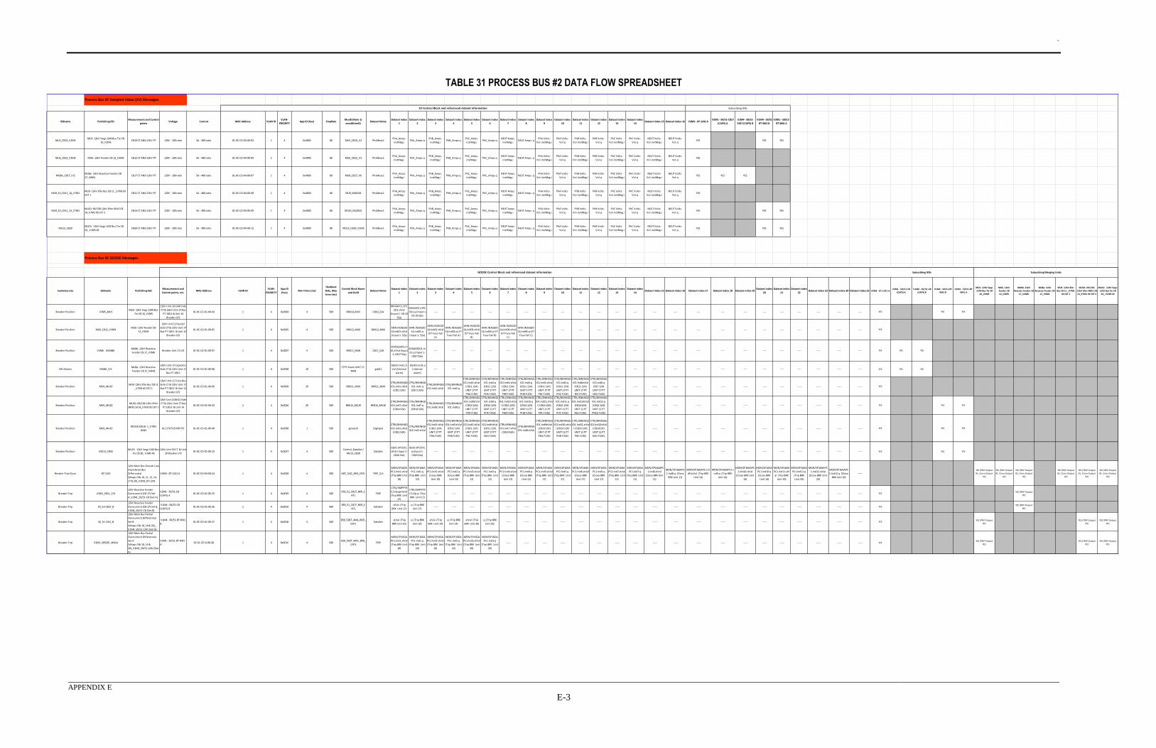
.
APPENDIX E
E-3
TABLE 31 PROCESS BUS #2 DATA FLOW SPREADSHEET
IEDname Publishing IEDMeasurement and Control
pointsVoltage Current MAC Address VLAN ID
VLAN-
PRIORITYApp ID (hex) SmpRate
MsvID (Note 1)
xxxxMUnn01Dataset Name
Dataset index
1
Dataset index
2
Dataset index
3
Dataset index
4
Dataset index
5
Dataset index
6
Dataset index
7
Dataset index
8
Dataset index
9
Dataset index
10
Dataset index
11
Dataset index
12
Dataset index
13
Dataset index
14Dataset index 15 Dataset index 16 V2M3 - 87-1241 A
V2M1 - 50/51-CB17
(CAPS) A
V1M4 - 50/51-
CB17 (CAPS) B
V1M4 - 50/51-
BT 4041 B
V2M1 - 50/51-
BT 4041 A
MU5_CB10_V2M5MU5- 12kV Swgr 1240 Bus Tie CB
10_V2M5 CB10 CT AND 12KV PT 120V - 100 ratio 5A - 400 ratio 01-0C-CD-04-00-04 1 4 0x4000 80 MU5_CB10_V2 PhsMeas1
PhA_Amps.
instMag.i PhA_Amps.q
PhB_Amps.
instMag.i PhB_Amps.q
PhC_Amps.
instMag.i PhC_Amps.q
NEUT Amps.
instMag.i NEUT Amps. q
PhA Volts-
Vol.instMag.i
PhA Volts-
Vol.q
PhB Volts-
Vol.instMag.i
PhB Volts-
Vol.q
PhC Volts-
Vol.instMag.i
PhC Volts-
Vol.q
NEUT Volts-
Vol.instMag.i
NEUT Volts-
Vol.qYES YES YES
MU6_CB12_V3M3 MU6- 12kV Feeder CB 12_V3M3 CB12 CT AND 12KV PT 120V - 100 ratio 5A - 400 ratio 01-0C-CD-04-00-05 1 4 0x4000 80 MU6_CB12_V3 PhsMeas1PhA_Amps.
instMag.i PhA_Amps.q
PhB_Amps.
instMag.i PhB_Amps.q
PhC_Amps.
instMag.i PhC_Amps.q
NEUT Amps.
instMag.i NEUT Amps. q
PhA Volts-
Vol.instMag.i
PhA Volts-
Vol.q
PhB Volts-
Vol.instMag.i
PhB Volts-
Vol.q
PhC Volts-
Vol.instMag.i
PhC Volts-
Vol.q
NEUT Volts-
Vol.instMag.i
NEUT Volts-
Vol.qYES
MU8A_CB17_VIZMU8a- 12kV Reactive Feeder CB
17_V6M1 CB17 CT AND 12KV PT 120V - 100 ratio 5A - 400 ratio 01-0C-CD-04-00-07 1 4 0x4000 80 MU8_CB17_V6 PhsMeas1
PhA_Amps.
instMag.i PhA_Amps.q
PhB_Amps.
instMag.i PhB_Amps.q
PhC_Amps.
instMag.i PhC_Amps.q
NEUT Amps.
instMag.i NEUT Amps. q
PhA Volts-
Vol.instMag.i
PhA Volts-
Vol.q
PhB Volts-
Vol.instMag.i
PhB Volts-
Vol.q
PhC Volts-
Vol.instMag.i
PhC Volts-
Vol.q
NEUT Volts-
Vol.instMag.i
NEUT Volts-
Vol.qYES YES YES
MU9_10_CB11_14_V7M1MU9- 12kV Xfer Bus CB 11 _V7M1 #2
CKT 1 CB11 CT AND 12KV PT 120V - 100 ratio 5A - 400 ratio 01-0C-CD-04-00-08 1 4 0x4000 80 MU9_MU0101 PhsMeas1
PhA_Amps.
instMag.i PhA_Amps.q
PhB_Amps.
instMag.i PhB_Amps.q
PhC_Amps.
instMag.i PhC_Amps.q
NEUT Amps.
instMag.i NEUT Amps. q
PhA Volts-
Vol.instMag.i
PhA Volts-
Vol.q
PhB Volts-
Vol.instMag.i
PhB Volts-
Vol.q
PhC Volts-
Vol.instMag.i
PhC Volts-
Vol.q
NEUT Volts-
Vol.instMag.i
NEUT Volts-
Vol.qYES
MU9_10_CB11_14_V7M1MU10- 69/138-12kV Xfmr BK41 CB
14_V7M1 #2 CKT 2 CB14 CT AND 12KV PT 120V - 100 ratio 5A - 400 ratio 01-0C-CD-04-00-09 1 4 0x4000 80 MU10_MU0201 PhsMeas1
PhA_Amps.
instMag.i PhA_Amps.q
PhB_Amps.
instMag.i PhB_Amps.q
PhC_Amps.
instMag.i PhC_Amps.q
NEUT Amps.
instMag.i NEUT Amps. q
PhA Volts-
Vol.instMag.i
PhA Volts-
Vol.q
PhB Volts-
Vol.instMag.i
PhB Volts-
Vol.q
PhC Volts-
Vol.instMag.i
PhC Volts-
Vol.q
NEUT Volts-
Vol.instMag.i
NEUT Volts-
Vol.qYES YES YES
MU13_CB20MU13- 12kV Swgr 1242 Bus Tie CB
20_ V1M5 #2 CB20 CT AND 12KV PT 120V - 100 ratio 5A - 400 ratio 01-0C-CD-04-00-12 1 4 0x4000 80 MU13_CB20_V1M5 PhsMeas1
PhA_Amps.
instMag.i PhA_Amps.q
PhB_Amps.
instMag.i PhB_Amps.q
PhC_Amps.
instMag.i PhC_Amps.q
NEUT Amps.
instMag.i NEUT Amps. q
PhA Volts-
Vol.instMag.i
PhA Volts-
Vol.q
PhB Volts-
Vol.instMag.i
PhB Volts-
Vol.q
PhC Volts-
Vol.instMag.i
PhC Volts-
Vol.q
NEUT Volts-
Vol.instMag.i
NEUT Volts-
Vol.qYES YES YES
Summary Use IEDname Publishing IEDMeasurement and
Control points, etc.MAC Address VLAN ID
VLAN-
PRIORITY
App ID
(hex)Min Trime (ms)
Heatbeat
Rate, Max
time (ms)
Control Block Name
and GoIDDataset Name
Dataset index
1
Dataset index
2
Dataset index
3
Dataset index
4
Dataset index
5
Dataset index
6
Dataset index
7
Dataset index
8
Dataset index
9
Dataset index
10
Dataset index
11
Dataset index
12
Dataset index
13
Dataset index
14Dataset index 15 Dataset index 16 Dataset index 17 Dataset index 18 Dataset index 19
Dataset index
20
Dataset index
21
Dataset index
22Dataset index 23 Dataset index 24 Dataset index 25 V2M3 - 87-1241 A
V2M1 - 50/51-CB
(CAPS) A
V1M4 - 50/51-CB
(CAPS) B
V1M4 - 50/51-BT
4041 B
V2M1 - 50/51-BT
4041 A
MU5- 12kV Swgr
1240 Bus Tie CB
10_V2M5
MU6- 12kV
Feeder CB
12_V3M3
MU8b- 12kV
Reactive Feeder CB
17_V2M6
MU8a- 12kV
Reactive Feeder CB
17_V6M1
MU9- 12kV Xfer
Bus CB 11 _V7M1
#2 CKT 1
MU10- 69/138-
12kV Xfmr BK41 CB
14_V7M1 #2 CKT 2
MU13- 12kV Swgr
1242 Bus Tie CB
20_ V1M5 #2
Breaker Position V2M5_MU5MU5- 12kV Swgr 1240 Bus
Tie CB 10_V2M5
12kV Unit 10 1240 Side
CT & 12kV Unit 17 Bus
PT 100:1 & Unit 10
Breaker I/O
01-0C-CD-01-00-04 1 4 0x0004 4 500 BRK10_MU5 CB10_52A
MVGAPC1.SPC
SO1.stVal
(Input 1- CB 10
52a)
MVGAPC1.SPC
SO1.q (Input 1-
CB 10 52a)
---- ---- ---- ---- ---- ---- ---- ---- ---- ---- ---- ---- ---- ---- ---- ---- ---- ---- ---- ---- ---- ---- ---- YES YES YES
Breaker Position MU6_CB12_V3M3MU6- 12kV Feeder CB
12_V3M3
12kV Unit 12 Feeder
Side CT & 12kV Unit 17
Bus PT 100:1 & Unit 12
Breaker I/O
01-0C-CD-01-00-05 1 4 0x0005 4 500 BRK12_MU6 BKR12_MU6
ANN.IN2GGIO
14,Ind01.stVal
(Input 1- 52a)
ANN.IN2GGIO
14,Ind01.q
(Input 1- 52a)
ANN.IN2GGIO
14,Ind02.stVal
(VT Fuse Fail
A)
ANN.IN2GGIO
14,Ind02.q (VT
Fuse Fail A)
ANN.IN2GGIO
14,Ind03.stVal
(VT Fuse Fail
B)
ANN.IN2GGIO
14,Ind03.q (VT
Fuse Fail B)
ANN.IN2GGIO
14,Ind04.stVal
(VT Fuse Fail
C)
ANN.IN2GGIO
14,Ind04.q (VT
Fuse Fail C)
---- ---- ---- ---- ---- ---- ---- ---- ---- ---- ---- ---- ---- ---- ---- ---- ---- YES
Breaker Position V2M6 (MU8B)MU8b- 12kV Reactive
Feeder CB 17_V2M6Breaker Unit 17 I/O 01-0C-CD-01-00-07 1 4 0x0007 4 500 BRK17_MU8 CB17_52A
SCMLGGIO1.In
d1.stVal (Input
1- CB17 52a)
SCMLGGIO1.In
d1.q (Input 1-
CB17 52a)
---- ---- ---- ---- ---- ---- ---- ---- ---- ---- ---- ---- ---- ---- ---- ---- ---- ---- ---- ---- ---- ---- ---- YES YES YES
MU Alarms MU8A_VIZMU8a- 12kV Reactive
Feeder CB 17_V6M1
12kV Unit 17 Capacitor
Side CT & 12kV Unit 17
Bus PT 100:1
01-0C-CD-01-00-08 1 4 0x0008 10 500CTPT Alarm UNIT 17-
MU8gcb01
GGIO1.Ind1.st
Val (internal
alarm)
GGIO1.Ind1.q
(internal
alarm)
---- ---- ---- ---- ---- ---- ---- ---- ---- ---- ---- ---- ---- ---- ---- ---- ---- ---- ---- ---- ---- ---- ---- YES YES YES
Breaker Position MU9_MU10MU9- 12kV Xfer Bus CB 11
_V7M1 #2 CKT 1
12kV Unit 11 Trans Bus
Side CT & 12kV Unit 17
Bus PT 100:2 & Unit 11
Breaker I/O
01-0C-CD-01-00-09 1 4 0x0009 20 500 BRK11_MU9 BKR11_MU9
CTRL/BININGG
IO1.Ind1.stVal
(CB11 52A)
CTRL/BININGG
IO1.Ind1.q
(CB11 52A)
CTRL/BININGG
IO1.Ind2.stVal
CTRL/BININGG
IO1.Ind2.q
CTRL/BININGG
IO1.Ind3.stVal
(CB11 1241
UNIT 17 PT
PHA FUSE)
CTRL/BININGG
IO1.Ind3.q
(CB11 1241
UNIT 17 PT
PHA FUSE)
CTRL/BININGG
IO1.Ind4.stVal
(CB11 1241
UNIT 17 PT
PHB FUSE)
CTRL/BININGG
IO1.Ind4.q
(CB11 1241
UNIT 17 PT
PHB FUSE)
CTRL/BININGG
IO1.Ind5.stVal
(CB11 1241
UNIT 17 PT
PHC FUSE)
CTRL/BININGG
IO1.Ind5.q
(CB11 1241
UNIT 17 PT
PHC FUSE)
CTRL/BININGG
IO1.Ind6stVal
(CB11 1241
UNIT 17 PT
NEU FUSE)
CTRL/BININGG
IO1.Ind6.q
(CB7 1241
UNIT 17 PT
NEU FUSE)
----- ----- ----- ----- ----- ----- ----- ----- ----- ----- ----- ----- ----- YES
Breaker Position MU9_MU10MU10- 69/138-12kV Xfmr
BK41 CB 14_V7M1 #2 CKT 2
12kV Unit 14 BK41 Side
CT & 12kV Unit 17 Bus
PT 100:3 & Unit 14
Breaker I/O
01-0C-CD-01-00-22 1 4 0x0016 20 500 BRK14_MU10 BKR14_MU10
CTRL/BININGG
IO1.Ind7.stVal
(CB14 52A)
CTRL/BININGG
IO1.Ind7.q
(CB14 52A)
CTRL/BININGG
IO1.Ind8.stVal
CTRL/BININGG
IO1.Ind8.q
CTRL/BININGG
IO1.Ind9stVal
(CB14 1241
UNIT 17 PT
PHA FUSE)
CTRL/BININGG
IO1.Ind9.q
(CB14 1241
UNIT 11 PT
PHA FUSE)
CTRL/BININGG
IO1.Ind10.stVa
l (CB14 1241
UNIT 11 PT
PHB FUSE)
CTRL/BININGG
IO1.Ind10.q
(CB14 1241
UNIT 11 PT
PHB FUSE)
CTRL/BININGG
IO1.Ind11.stVa
l (CB14 1241
UNIT 11 PT
PHC FUSE)
CTRL/BININGG
IO1.Ind11.q
(CB14 1241
UNIT 11 PT
PHC FUSE)
CTRL/BININGG
IO1.Ind12stVal
(CB141241
UNIT 11 PT
NEU FUSE)
CTRL/BININGG
IO1.Ind12.q
(CB14 1241
UNIT 11 PT
PNEU FUSE)
----- ----- ----- ----- ----- ----- ----- ----- ----- ----- ----- ----- ----- YES YES YES
Breaker Position MU9_MU10MU9 & MU10- 1_V7M1
#1&2 ALL STATUS INPUTS 01-0C-CD-01-00-40 1 4 0x0028 1 500 gooseID DigInput
CTRL/BININGG
IO1.Ind1.stVal
(CB11 52A)
CTRL/BININGG
IO1.Ind2.stVal
CTRL/BININGG
IO1.Ind3.stVal
(CB11 1241
UNIT 17 PT
PHA FUSE)
CTRL/BININGG
IO1.Ind4.stVal
(CB11 1241
UNIT 17 PT
PHB FUSE)
CTRL/BININGG
IO1.Ind5.stVal
(CB11 1241
UNIT 17 PT
PHC FUSE)
CTRL/BININGG
IO1.Ind6stVal
(CB11 1241
UNIT 17 PT
NEU FUSE)
CTRL/BININGG
IO1.Ind7.stVal
(CB14 52A)
CTRL/BININGG
IO1.Ind8.stVal
CTRL/BININGG
IO1.Ind9stVal
(CB14 1241
UNIT 17 PT
PHA FUSE)
CTRL/BININGG
IO1.Ind10.stVa
l (CB14 1241
UNIT 11 PT
PHB FUSE)
CTRL/BININGG
IO1.Ind11.stVa
l (CB14 1241
UNIT 11 PT
PHC FUSE)
CTRL/BININGG
IO1.Ind12stVal
(CB141241
UNIT 11 PT
NEU FUSE)
----- ----- ----- ----- ----- ----- ----- ----- ----- ----- ----- ----- ----- YES YES YES
Breaker Position MU13_CB20MU13- 12kV Swgr 1242 Bus
Tie CB 20_ V1M5 #2
12kV Unit 20 CT & Unit
20 Breaker I/O01-0C-CD-01-00-23 1 4 0x0017 4 500
Control_DataSet /
MU13_CB20DataSet
GGIO.SPCSO1.
stVal (Input 1-
CB20 52a)
GGIO.SPCSO1.
q (Input 1-
CB20 52a)
----- ----- ----- ----- ----- ----- ----- ----- ----- ----- ----- ----- ----- ----- ----- ----- ----- ----- ----- ----- ----- ----- ----- YES YES YES
Breaker Trip-Close 87-1241
12kV Main Bus Overall Low
Impedance Bus
Differential
(Wraps CBs 10, 11, 12, 14,
17 & 20)_V2M3_87-1241
V2M3 - 87-1241 A 01-0C-CD-04-00-24 1 4 0x0018 4 500 A87_1241_BKR_CNTL TRIP_CLS
MON/SP16GA
PC1.Ind1.stVal
(Trip BRK Unit
10)
MON/SP16GA
PC1.Ind1.q
(Trip BRK Unit
10)
MON/SP16GA
PC1.Ind2.stVal
(Close BRK
Unit 10)
MON/SP16GA
PC1.Ind2.q
(Close BRK
Unit 10)
MON/SP16GA
PC1.Ind3.stVal
(Trip BRK Unit
12)
MON/SP16GA
PC1.Ind3.q
(Trip BRK Unit
12)
MON/SP16GA
PC1.Ind4.stVal
(Close BRK
Unit 12)
MON/SP16GA
PC1.Ind4.q
(Close BRK
Unit 12)
MON/SP16GA
PC1.Ind5.stVal
(Trip BRK Unit
17)
MON/SP16GA
PC1.Ind5.q
(Trip BRK Unit
17)
MON/SP16GA
PC1.Ind6.stVal
(Close BRK
Unit 17)
MON/SP16GA
PC1.Ind6.q
(Close BRK
Unit 17)
MON/SP16GA
PC1.Ind7.stVal
(Trip BRK Unit
11)
MON/SP16GA
PC1.Ind7.q
(Trip BRK Unit
11)
MON/SP16GAPC
1.Ind8.stVal
(Close BRK Unit
11)
MON/SP16GAPC
1.Ind8.q (Close
BRK Unit 11)
MON/SP16GAPC1.In
d9.stVal (Trip BRK
Unit 14)
MON/SP16GAPC1.I
nd9.q (Trip BRK
Unit 14)
MON/SP16GAPC
1.Ind10.stVal
(Close BRK Unit
14)
MON/SP16GA
PC1.Ind10.q
(Close BRK
Unit 14)
MON/SP16GA
PC1.Ind11.stV
al (Trip BRK
Unit 20)
MON/SP16GA
PC1.Ind11.q
(Trip BRK
Unit 20)
MON/SP16GAPC
1.Ind12.stVal
(Close BRK Unit
20)
MON/SP16GAPC
1.Ind12.q (Close
BRK Unit 20)
-----YES (TRIP Output
#1, Close Output
#2)
YES (TRIP Output
#1, Close Output
#2)
YES (TRIP Output
#1, Close Output
#2)
YES (TRIP Output
#1, Close Output
#2)
YES (TRIP Output
#1, Close Output
#2)
YES (TRIP Output
#1, Close Output
#2)
Breaker Trip V2M1_5051_17A
12kV Reactive Feeder
Overcurrent (CB 17) Set
A_V2M1_50/51-CB (Set A)
V2M1 - 50/51-CB
(CAPS) A01-0C-CD-01-00-25 1 4 0x0019 4 500
A50_51_CB17_BKR_C
NTLTRIP
CTRL/SMPPTR
C1.Op.general
(Trip BRK Unit
17)
CTRL/SMPPTR
C1.Op.q (Trip
BRK Unit 17)
----- ----- ----- ----- ----- ----- ----- ----- ----- ----- ----- ----- ----- ----- ----- ----- ----- ----- ----- ----- ----- ----- ----- YESYES (TRIP Output
#1)
Breaker Trip 50_51-CB17_B
12kV Reactive Feeder
Overcurrent (CB 17) Set B_
V1M4_50/51-CB (Set B)
V1M4 - 50/51-CB
(CAPS) B01-0C-CD-01-00-26 1 4 0x001A 4 500
B50_51_CB17_BKR_C
NTLDataSet
.stVal (Trip
BRK Unit 17)
.q (Trip BRK
Unit 17) ----- ----- ----- ----- ----- ----- ----- ----- ----- ----- ----- ----- ----- ----- ----- ----- ----- ----- ----- ----- ----- ----- ----- YES
YES (TRIP Output
#1)
Breaker Trip 50_51-1241_B
12kV Main Bus Partial
Overcurrent Differential
Set B
(Wraps CBs 10, 14 & 20)_
V1M4_50/51-1241 (Set B)
V1M4 - 50/51-BT 4041
B01-0C-CD-01-00-27 1 4 0x001B 4 500
B50_51BT_4041_BKR_
CNTLDataSet
.stVal (Trip
BRK Unit 10)
.q (Trip BRK
Unit 10)
.stVal (Trip
BRK Unit 14)
.q (Trip BRK
Unit 14)
.stVal (Trip
BRK Unit 20)
.q (Trip BRK
Unit 20) ----- ----- ----- ----- ----- ----- ----- ----- ----- ----- ----- ----- ----- ----- ----- ----- ----- ----- ----- YES
YES (TRIP Output
#1)
YES (TRIP Output
#1)
YES (TRIP Output
#1)
Breaker Trip V2M1_5051BT_4041A
12kV Main Bus Partial
Overcurrent Differential
Set A
(Wraps CBs 10, 14 &
20)_V2M1_50/51-1241 (Set
A)
V2M1 - 50/51-BT 4041
A01-0C-CD-0-00-28 1 4 0x001C 4 500
A50_51BT_4041_BKR_
CNTLTRIP
MON/SP16GA
PC1.Ind1.stVal
(Trip BRK Unit
10)
MON/SP16GA
PC1.Ind1.q
(Trip BRK Unit
10)
MON/SP16GA
PC1.Ind2.stVal
(Trip BRK Unit
14)
MON/SP16GA
PC1.Ind2.q
(Trip BRK Unit
14)
MON/SP16GA
PC1.Ind3.stVal
(Trip BRK Unit
20)
MON/SP16GA
PC1.Ind3.q
(Trip BRK Unit
20)
----- ----- ----- ----- ----- ----- ----- ----- ----- ----- ----- ----- ----- ----- ----- ----- ----- ----- ----- YESYES (TRIP Output
#1)
YES (TRIP Output
#1)
YES (TRIP Output
#1)
Subscribing Merging Units
Process Bus #2 Sampled Value (SV) Messages
SV Control Block and referenced dataset information Subscribing IEDs
Process Bus #2 GOOSE Messages
Subscribing IEDsGOOSE Control Block and referenced dataset information
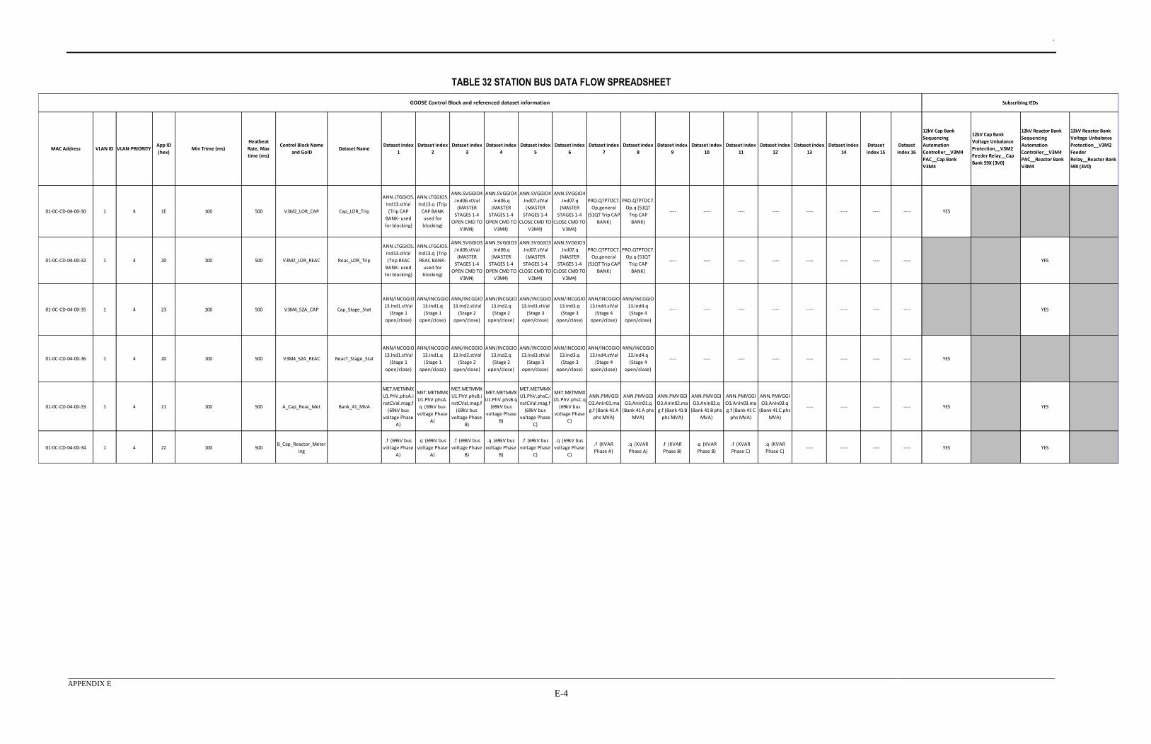
.
APPENDIX E
E-4
TABLE 32 STATION BUS DATA FLOW SPREADSHEET
MAC Address VLAN ID VLAN-PRIORITYApp ID
(hex)Min Trime (ms)
Heatbeat
Rate, Max
time (ms)
Control Block Name
and GoIDDataset Name
Dataset index
1
Dataset index
2
Dataset index
3
Dataset index
4
Dataset index
5
Dataset index
6
Dataset index
7
Dataset index
8
Dataset index
9
Dataset index
10
Dataset index
11
Dataset index
12
Dataset index
13
Dataset index
14
Dataset
index 15
Dataset
index 16
12kV Cap Bank
Sequencing
Automation
Controller__V3M4
PAC__Cap Bank
V3M4
12kV Cap Bank
Voltage Unbalance
Protection__V3M2
Feeder Relay__Cap
Bank 59X (3V0)
12kV Reactor Bank
Sequencing
Automation
Controller__V3M4
PAC__Reactor Bank
V3M4
12kV Reactor Bank
Voltage Unbalance
Protection__V3M2
Feeder
Relay__Reactor Bank
59X (3V0)
01-0C-CD-04-00-30 1 4 1E 100 500 V3M2_LOR_CAP Cap_LOR_Trip
ANN.LTGGIO5.
Ind13.stVal
(Trip CAP
BANK- used
for blocking)
ANN.LTGGIO5.
Ind13.q (Trip
CAP BANK
used for
blocking)
ANN.SVGGIO4
.Ind06.stVal
(MASTER
STAGES 1-4
OPEN CMD TO
V3M4)
ANN.SVGGIO4
.Ind06.q
(MASTER
STAGES 1-4
OPEN CMD TO
V3M4)
ANN.SVGGIO4
.Ind07.stVal
(MASTER
STAGES 1-4
CLOSE CMD TO
V3M4)
ANN.SVGGIO4
.Ind07.q
(MASTER
STAGES 1-4
CLOSE CMD TO
V3M4)
PRO.QTPTOC7.
Op.general
(51QT Trip CAP
BANK)
PRO.QTPTOC7.
Op.q (51QT
Trip CAP
BANK)
---- ---- ---- ---- ---- ---- ---- ---- YES
01-0C-CD-04-00-32 1 4 20 100 500 V3M2_LOR_REAC Reac_LOR_Trip
ANN.LTGGIO5.
Ind13.stVal
(Trip REAC
BANK- used
for blocking)
ANN.LTGGIO5.
Ind13.q (Trip
REAC BANK-
used for
blocking)
ANN.SVGGIO3
.Ind06.stVal
(MASTER
STAGES 1-4
OPEN CMD TO
V3M4)
ANN.SVGGIO3
.Ind06.q
(MASTER
STAGES 1-4
OPEN CMD TO
V3M4)
ANN.SVGGIO3
.Ind07.stVal
(MASTER
STAGES 1-4
CLOSE CMD TO
V3M4)
ANN.SVGGIO3
.Ind07.q
(MASTER
STAGES 1-4
CLOSE CMD TO
V3M4)
PRO.QTPTOC7.
Op.general
(51QT Trip CAP
BANK)
PRO.QTPTOC7.
Op.q (51QT
Trip CAP
BANK)
---- ---- ---- ---- ---- ---- ---- ---- YES
01-0C-CD-04-00-35 1 4 23 100 500 V3M4_52A_CAP Cap_Stage_Stat
ANN/INCGGIO
13.Ind1.stVal
(Stage 1
open/close)
ANN/INCGGIO
13.Ind1.q
(Stage 1
open/close)
ANN/INCGGIO
13.Ind2.stVal
(Stage 2
open/close)
ANN/INCGGIO
13.Ind2.q
(Stage 2
open/close)
ANN/INCGGIO
13.Ind3.stVal
(Stage 3
open/close)
ANN/INCGGIO
13.Ind3.q
(Stage 3
open/close)
ANN/INCGGIO
13.Ind4.stVal
(Stage 4
open/close)
ANN/INCGGIO
13.Ind4.q
(Stage 4
open/close)
---- ---- ---- ---- ---- ---- ---- ---- YES
01-0C-CD-04-00-36 1 4 20 100 500 V3M4_52A_REAC ReacT_Stage_Stat
ANN/INCGGIO
13.Ind1.stVal
(Stage 1
open/close)
ANN/INCGGIO
13.Ind1.q
(Stage 1
open/close)
ANN/INCGGIO
13.Ind2.stVal
(Stage 2
open/close)
ANN/INCGGIO
13.Ind2.q
(Stage 2
open/close)
ANN/INCGGIO
13.Ind3.stVal
(Stage 3
open/close)
ANN/INCGGIO
13.Ind3.q
(Stage 3
open/close)
ANN/INCGGIO
13.Ind4.stVal
(Stage 4
open/close)
ANN/INCGGIO
13.Ind4.q
(Stage 4
open/close)
---- ---- ---- ---- ---- ---- ---- ---- YES
01-0C-CD-04-00-33 1 4 21 100 500 A_Cap_Reac_Met Bank_41_MVA
MET.METMMX
U1.PhV.phsA.i
nstCVal.mag.f
(69kV bus
voltage Phase
A)
MET.METMMX
U1.PhV.phsA.
q (69kV bus
voltage Phase
A)
MET.METMMX
U1.PhV.phsB.i
nstCVal.mag.f
(69kV bus
voltage Phase
B)
MET.METMMX
U1.PhV.phsB.q
(69kV bus
voltage Phase
B)
MET.METMMX
U1.PhV.phsC.i
nstCVal.mag.f
(69kV bus
voltage Phase
C)
MET.METMMX
U1.PhV.phsC.q
(69kV bus
voltage Phase
C)
ANN.PMVGGI
O3.AnIn01.ma
g.f (Bank 41 A
phs MVA)
ANN.PMVGGI
O3.AnIn01.q
(Bank 41 A phs
MVA)
ANN.PMVGGI
O3.AnIn02.ma
g.f (Bank 41 B
phs MVA)
ANN.PMVGGI
O3.AnIn02.q
(Bank 41 B phs
MVA)
ANN.PMVGGI
O3.AnIn03.ma
g.f (Bank 41 C
phs MVA)
ANN.PMVGGI
O3.AnIn03.q
(Bank 41 C phs
MVA)
---- ---- ---- ---- YES YES
01-0C-CD-04-00-34 1 4 22 100 500B_Cap_Reactor_Meter
ing
.f (69kV bus
voltage Phase
A)
.q (69kV bus
voltage Phase
A)
.f (69kV bus
voltage Phase
B)
.q (69kV bus
voltage Phase
B)
.f (69kV bus
voltage Phase
C)
.q (69kV bus
voltage Phase
C)
.f (KVAR
Phase A)
.q (KVAR
Phase A)
.f (KVAR
Phase B)
.q (KVAR
Phase B)
.f (KVAR
Phase C)
.q (KVAR
Phase C) ---- ---- ---- ---- YES YES
GOOSE Control Block and referenced dataset information Subscribing IEDs
.
APPENDIX F
F-1
APPENDIX F - COMTRADE GRAPHICAL ANALYSIS Appendix F contains the raw COMTRADE file data for each of the fault cases analyzed. Information
is divided into analog signals (voltage, current, frequency, etc.) and digital signals (protection element
pickup/operate, 52A breaker statuses, etc.) for each relay. Analog signals utilized custom naming
where appropriate to identify the channels, whereas digital signals utilized the naming assigned by a
given protective relay.
For each case, the fault inception point is marked with a vertical orange line. A vertical blue line
denotes the operate time of a protection element or a corresponding 52A dropout time, as appropriate
for the fault analyzed. Appendix G contains timing data and additional analysis of the COMTRADE
data presented.
Note: some relays produce more digital signals than in use for the given application, or reported no
activity on particular digital signal channels. Blank digital element plots were left in the dataset to
demonstrate non-operation of protective elements for a given fault scenario.
Note to Reader: Due to its size and format of the graphics, the content of Appendix F is provided
in a separate PDF file and is not included in this MS Word document.
.
APPENDIX G
G-1
APPENDIX G - OPERATING TIMES SPREADSHEET Appendix G contains the timing information extracted from the raw COMTRADE file data presented
in Appendix F. The tables list each fault location analyzed, the fault type, and operate times related to
the protective elements under investigation (pickup, trip, and 52A dropout). All timings reported
were based on normalizing the fault initiation to a time of zero milli-seconds. Total operate times and
the round-trip 52A dropout time conveyed through the network are presented in milli-seconds and
cycles (cyc). Relays associated with several circuit breakers (e.g., the 12 kV bus differential relay)
have multiple 52A dropout times listed, with corresponding notes that indicate which simulated
circuit breaker corresponds to the 52A dropout time reported.
For each fault location, notes are included to discuss the test performed and results obtained. These
notes correlate to the faults listed in the table, as well as documented in the raw COMTRADE plots in
Appendix F.
Note: results related to the capacitor/reactor automation testing were reported in Appendix F.
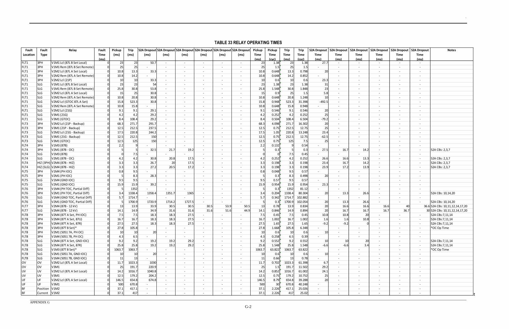
.
APPENDIX G
G-2
TABLE 33 RELAY OPERATING TIMES
t
Fault
Location
Fault
Type
Relay Fault
Time
(ms)
Pickup
(ms)
Trip
(ms)
52A Dropout
(ms)
52A Dropout
(ms)
52A Dropout
(ms)
52A Dropout
(ms)
52A Dropout
(ms)
52A Dropout
(ms)
Pickup
Time
(ms)
Pickup
Time
(cyc)
Trip
Time
(ms)
Trip
Time
(cyc)
52A Dropout
Time
(ms)
52A Dropout
Time
(ms)
52A Dropout
Time
(ms)
52A Dropout
Time
(ms)
52A Dropout
Time
(ms)
52A Dropout
Time
(ms)
Notes
FLT1 3PH V1M1 Lcl (87L B Set Local) 0 23 23 50.7 - - - - - 23 1.38 23 1.38 27.7 - - - - -
FLT1 3PH V1M1 Rem (87L B Set Remote) 0 25 25 - - - - - - 25 1.5 25 1.5 - - - - - -
FLT1 3PH V2M2 Lcl (87L A Set Local) 0 10.8 13.3 33.3 - - - - - 10.8 0.648 13.3 0.798 20 - - - - -
FLT1 3PH V2M2 Rem (87L A Set Remote) 0 10.8 14.2 - - - - - - 10.8 0.648 14.2 0.852 - - - - - -
FLT1 3PH V2M2 Lcl (21P) 0 10 10 33.3 - - - - - 10 0.6 10 0.6 23.3 - - - - -
FLT1 SLG V1M1 Lcl (87L B Set Local) 0 23 23 54 - - - - - 23 1.38 23 1.38 31 - - - - -
FLT1 SLG V1M1 Rem (87L B Set Remote) 0 25.8 30.8 53.8 - - - - - 25.8 1.548 30.8 1.848 23 - - - - -
FLT1 SLG V2M2 Lcl (87L A Set Local) 0 15 25 30.8 - - - - - 15 0.9 25 1.5 5.8 - - - - -
FLT1 SLG V2M2 Rem (87L A Set Remote) 0 10.8 20.8 30.8 - - - - - 10.8 0.648 20.8 1.248 10 - - - - -
FLT1 SLG V2M2 Lcl (GTOC 87L A Set) 0 15.8 523.3 30.8 - - - - - 15.8 0.948 523.3 31.398 -492.5 - - - - -
FLT1 SLG V2M2 Rem (87L A Set Remote) 0 10.8 15.8 - - - - - - 10.8 0.648 15.8 0.948 - - - - - -
FLT1 SLG V2M2 Lcl (21G) 0 9.1 9.1 29.1 - - - - - 9.1 0.546 9.1 0.546 20 - - - - -
FLT1 SLG V3M1 (21G) 0 4.2 4.2 29.2 - - - - - 4.2 0.252 4.2 0.252 25 - - - - -
FLT1 SLG V3M1 (GTOC) 0 8.4 108.4 29.2 - - - - - 8.4 0.504 108.4 6.504 -79.2 - - - - -
FLT3 3PH V2M2 Lcl (21P - Backup) 0 68.3 271.7 291.7 - - - - - 68.3 4.098 271.7 16.302 20 - - - - -
FLT3 3PH V3M1 (21P - Backup) 0 12.5 212.5 237.5 - - - - - 12.5 0.75 212.5 12.75 25 - - - - -
FLT3 SLG V2M2 Lcl (21G - Backup) 0 17.5 220.8 244.2 - - - - - 17.5 1.05 220.8 13.248 23.4 - - - - -
FLT3 SLG V3M1 (21G - Backup) 0 12.5 212.5 150 - - - - - 12.5 0.75 212.5 12.75 -62.5 - - - - -
FLT3 SLG V3M1 (GTOC) 0 12.5 125 150 - - - - - 12.5 0.75 125 7.5 25 - - - - -
FLT4 3PH V1M3 (87B) 0 2.2 9 - - - - - - 2.2 0.132 9 0.54 - - - - - -
FLT4 3PH V2M1 (87B - OC) 0 5 5 32.5 21.7 19.2 - - - 5 0.3 5 0.3 27.5 16.7 14.2 - - - 52A CBs: 2,3,7
FLT4 SLG V1M3 (87B) 0 0 7.5 - - - - - - 0 0 7.5 0.45 - - - - - -
FLT4 SLG V2M1 (87B - OC) 0 4.2 4.2 30.8 20.8 17.5 - - - 4.2 0.252 4.2 0.252 26.6 16.6 13.3 - - - 52A CBs: 2,3,7
FLT4 HIZ (3PH) V2M4 (87B - HIZ) 0 3.3 3.3 26.7 20 17.5 - - - 3.3 0.198 3.3 0.198 23.4 16.7 14.2 - - - 52A CBs: 2,3,7
FLT4 HIZ (SLG) V2M4 (87B - HIZ) 0 3.3 3.3 27.2 20.5 17.2 - - - 3.3 0.198 3.3 0.198 23.9 17.2 13.9 - - - 52A CBs: 2,3,7
FLT5 3PH V1M4 (PH IOC) 0 0.8 9.5 - - - - - - 0.8 0.048 9.5 0.57 - - - - - -
FLT5 3PH V2M1 (PH IOC) 0 5 8.3 28.3 - - - - - 5 0.3 8.3 0.498 20 - - - - -
FLT5 SLG V1M4 (GND IOC) 0 9.5 9.5 - - - - - - 9.5 0.57 9.5 0.57 - - - - - -
FLT5 SLG V2M1 (GND IOC) 0 15.9 15.9 39.2 - - - - - 15.9 0.954 15.9 0.954 23.3 - - - - -
FLT6 3PH V1M4 (PH TOC, Partial Diff) 0 5 1352 - - - - - - 5 0.3 1352 81.12 - - - - - -
FLT6 3PH V2M1 (PH TOC, Partial Diff) 0 3.4 1338.4 1358.4 1351.7 1365 - - - 3.4 0.204 1338.4 80.304 20 13.3 26.6 - - - 52A CBs: 10,14,20
FLT6 SLG V1M4 (GND TOC, Partial Diff) 0 5.7 1714.7 - - - - - - 5.7 0.342 1714.7 102.882 - - - - - -
FLT6 SLG V2M1 (GND TOC, Partial Diff) 0 5 1700.9 1720.9 1714.2 1727.5 - - - 5 0.3 1700.9 102.054 20 13.3 26.6 - - - 52A CBs: 10,14,20
FLT7 3PH V2M4 (87B - 12 kV) 0 13 13.9 33.9 30.5 30.5 30.5 53.9 50.5 13 0.78 13.9 0.834 20 16.6 16.6 16.6 40 36.6 52A CBs: 10,11,12,14,17,20
FLT7 SLG V2M4 (87B - 12 kV) 0 14.1 14.9 34.9 31.6 31.6 31.6 51.6 44.9 14.1 0.846 14.9 0.894 20 16.7 16.7 16.7 36.7 30 52A CBs: 10,11,12,14,17,20
FLT8 3PH V2M4 (87T A Set, PH IOC) 0 7.5 7.5 18.3 18.3 27.5 - - - 7.5 0.45 7.5 0.45 10.8 10.8 20 - - - 52A CBs:7,11,14
FLT8 3PH V2M4 (87T A Set, 87U) 0 16.7 16.7 18.3 18.3 27.5 - - - 16.7 1.002 16.7 1.002 1.6 1.6 10.8 - - - 52A CBs:7,11,14
FLT8 3PH V2M4 (87T A Set, 87R) 0 27.5 27.5 18.3 18.3 27.5 - - - 27.5 1.65 27.5 1.65 -9.2 -9.2 0 - - - 52A CBs:7,11,14
FLT8 3PH V1M3 (87T B Set)* 0 27.8 105.8 - - - - - - 27.8 1.668 105.8 6.348 - - - - - - *OC Op Time
FLT8 3PH V2M1 (5051 7A, PH OC) 0 10 10 20 - - - - - 10 0.6 10 0.6 10 - - - - -
FLT8 3PH V1M4 (5051 7B, PH OC) 0 4.3 6.5 - - - - - - 4.3 0.258 6.5 0.39 - - - - - -
FLT8 SLG V2M4 (87T A Set, GND IOC) 0 9.2 9.2 19.2 19.2 29.2 - - - 9.2 0.552 9.2 0.552 10 10 20 - - - 52A CBs:7,11,14
FLT8 SLG V2M4 (87T A Set, 87R) 0 25.8 25.8 19.2 19.2 29.2 - - - 25.8 1.548 25.8 1.548 -6.6 -6.6 3.4 - - - 52A CBs:7,11,14
FLT8 SLG V1M3 (87T B Set)* 0 1063.7 1063.7 - - - - - - 1063.7 63.822 1063.7 63.822 - - - - - - *OC Op Time
FLT8 SLG V2M1 (5051 7A, GND IOC) 0 10 10 20 - - - - - 10 0.6 10 0.6 10 - - - - -
FLT8 SLG V1M4 (5051 7B, GND IOC) 0 11 13 - - - - - - 11 0.66 13 0.78 - - - - - -
OV OV V2M2 Lcl (87L A Set Local) 0 11.7 1023.3 1030 - - - - - 11.7 0.702 1023.3 61.398 6.7 - - - - -
OV OV V3M1 0 25 191.7 220.9 - - - - - 25 1.5 191.7 11.502 29.2 - - - - -
UV UV V2M2 Lcl (87L A Set Local) 0 14.2 1016.7 1040.8 - - - - - 14.2 0.852 1016.7 61.002 24.1 - - - - -
UV UV V3M1 0 12.5 179.2 204.2 - - - - - 12.5 0.75 179.2 10.752 25 - - - - -
UF UF V2M2 Lcl (87L A Set Local) 0 146.5 654.8 674.8 - - - - - 146.5 8.79 654.8 39.288 20 - - - - -
UF UF V3M1 0 500 670.8 - - - - - - 500 30 670.8 40.248 - - - - - -
BF Position V1M2 0 37.1 417.1 - - - - - - 37.1 2.226 417.1 25.026 - - - - - -
BF Current V1M2 0 37.1 417 - - - - - - 37.1 2.226 417 25.02 - - - - - -
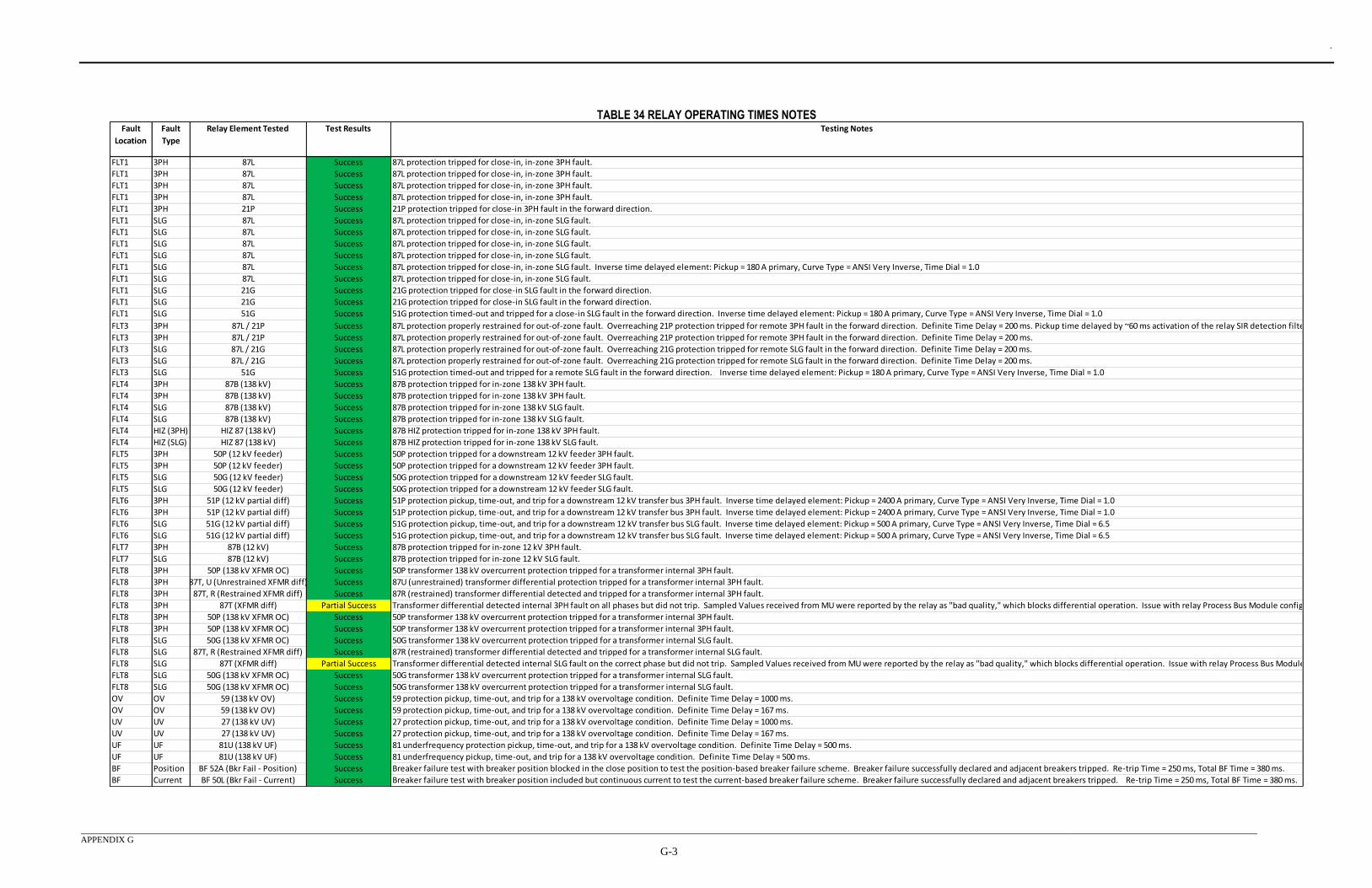
.
APPENDIX G
G-3
TABLE 34 RELAY OPERATING TIMES NOTESFault
Location
Fault
Type
Relay Element Tested Test Results
FLT1 3PH 87L Success
FLT1 3PH 87L Success
FLT1 3PH 87L Success
FLT1 3PH 87L Success
FLT1 3PH 21P Success
FLT1 SLG 87L Success
FLT1 SLG 87L Success
FLT1 SLG 87L Success
FLT1 SLG 87L Success
FLT1 SLG 87L Success
FLT1 SLG 87L Success
FLT1 SLG 21G Success
FLT1 SLG 21G Success
FLT1 SLG 51G Success
FLT3 3PH 87L / 21P Success
FLT3 3PH 87L / 21P Success
FLT3 SLG 87L / 21G Success
FLT3 SLG 87L / 21G Success
FLT3 SLG 51G Success
FLT4 3PH 87B (138 kV) Success
FLT4 3PH 87B (138 kV) Success
FLT4 SLG 87B (138 kV) Success
FLT4 SLG 87B (138 kV) Success
FLT4 HIZ (3PH) HIZ 87 (138 kV) Success
FLT4 HIZ (SLG) HIZ 87 (138 kV) Success
FLT5 3PH 50P (12 kV feeder) Success
FLT5 3PH 50P (12 kV feeder) Success
FLT5 SLG 50G (12 kV feeder) Success
FLT5 SLG 50G (12 kV feeder) Success
FLT6 3PH 51P (12 kV partial diff) Success
FLT6 3PH 51P (12 kV partial diff) Success
FLT6 SLG 51G (12 kV partial diff) Success
FLT6 SLG 51G (12 kV partial diff) Success
FLT7 3PH 87B (12 kV) Success
FLT7 SLG 87B (12 kV) Success
FLT8 3PH 50P (138 kV XFMR OC) Success
FLT8 3PH 87T, U (Unrestrained XFMR diff) Success
FLT8 3PH 87T, R (Restrained XFMR diff) Success
FLT8 3PH 87T (XFMR diff) Partial Success
FLT8 3PH 50P (138 kV XFMR OC) Success
FLT8 3PH 50P (138 kV XFMR OC) Success
FLT8 SLG 50G (138 kV XFMR OC) Success
FLT8 SLG 87T, R (Restrained XFMR diff) Success
FLT8 SLG 87T (XFMR diff) Partial Success
FLT8 SLG 50G (138 kV XFMR OC) Success
FLT8 SLG 50G (138 kV XFMR OC) Success
OV OV 59 (138 kV OV) Success
OV OV 59 (138 kV OV) Success
UV UV 27 (138 kV UV) Success
UV UV 27 (138 kV UV) Success
UF UF 81U (138 kV UF) Success
UF UF 81U (138 kV UF) Success
BF Position BF 52A (Bkr Fail - Position) Success
BF Current BF 50L (Bkr Fail - Current) Success
21P protection tripped for close-in 3PH fault in the forward direction.
Testing Notes
87L protection tripped for close-in, in-zone 3PH fault.
87L protection tripped for close-in, in-zone 3PH fault.
87L protection tripped for close-in, in-zone 3PH fault.
87L protection tripped for close-in, in-zone 3PH fault.
87L protection tripped for close-in, in-zone SLG fault.
87L protection tripped for close-in, in-zone SLG fault.
87L protection tripped for close-in, in-zone SLG fault.
87L protection tripped for close-in, in-zone SLG fault.
21G protection tripped for close-in SLG fault in the forward direction.
87L protection tripped for close-in, in-zone SLG fault.
87L protection tripped for close-in, in-zone SLG fault. Inverse time delayed element: Pickup = 180 A primary, Curve Type = ANSI Very Inverse, Time Dial = 1.0
51G protection timed-out and tripped for a remote SLG fault in the forward direction. Inverse time delayed element: Pickup = 180 A primary, Curve Type = ANSI Very Inverse, Time Dial = 1.0
87B protection tripped for in-zone 138 kV 3PH fault.
87B protection tripped for in-zone 138 kV SLG fault.
87B HIZ protection tripped for in-zone 138 kV SLG fault.
50G protection tripped for a downstream 12 kV feeder SLG fault.
87B HIZ protection tripped for in-zone 138 kV 3PH fault.
87B protection tripped for in-zone 138 kV SLG fault.
87B protection tripped for in-zone 138 kV 3PH fault.
50P protection tripped for a downstream 12 kV feeder 3PH fault.
50P transformer 138 kV overcurrent protection tripped for a transformer internal 3PH fault.
59 protection pickup, time-out, and trip for a 138 kV overvoltage condition. Definite Time Delay = 1000 ms.
81 underfrequency protection pickup, time-out, and trip for a 138 kV overvoltage condition. Definite Time Delay = 500 ms.
87R (restrained) transformer differential detected and tripped for a transformer internal SLG fault.
50G transformer 138 kV overcurrent protection tripped for a transformer internal SLG fault.
59 protection pickup, time-out, and trip for a 138 kV overvoltage condition. Definite Time Delay = 167 ms.
27 protection pickup, time-out, and trip for a 138 kV overvoltage condition. Definite Time Delay = 1000 ms.
27 protection pickup, time-out, and trip for a 138 kV overvoltage condition. Definite Time Delay = 167 ms.
Breaker failure test with breaker position blocked in the close position to test the position-based breaker failure scheme. Breaker failure successfully declared and adjacent breakers tripped. Re-trip Time = 250 ms, Total BF Time = 380 ms.
Breaker failure test with breaker position included but continuous current to test the current-based breaker failure scheme. Breaker failure successfully declared and adjacent breakers tripped. Re-trip Time = 250 ms, Total BF Time = 380 ms.
Transformer differential detected internal SLG fault on the correct phase but did not trip. Sampled Values received from MU were reported by the relay as "bad quality," which blocks differential operation. Issue with relay Process Bus Module configuration.
50G transformer 138 kV overcurrent protection tripped for a transformer internal SLG fault.
50G transformer 138 kV overcurrent protection tripped for a transformer internal SLG fault.
81 underfrequency pickup, time-out, and trip for a 138 kV overvoltage condition. Definite Time Delay = 500 ms.
50P transformer 138 kV overcurrent protection tripped for a transformer internal 3PH fault.
Transformer differential detected internal 3PH fault on all phases but did not trip. Sampled Values received from MU were reported by the relay as "bad quality," which blocks differential operation. Issue with relay Process Bus Module configuration.
87R (restrained) transformer differential detected and tripped for a transformer internal 3PH fault.
87B protection tripped for in-zone 12 kV 3PH fault.
50P protection tripped for a downstream 12 kV feeder 3PH fault.
51P protection pickup, time-out, and trip for a downstream 12 kV transfer bus 3PH fault. Inverse time delayed element: Pickup = 2400 A primary, Curve Type = ANSI Very Inverse, Time Dial = 1.0
51G protection pickup, time-out, and trip for a downstream 12 kV transfer bus SLG fault. Inverse time delayed element: Pickup = 500 A primary, Curve Type = ANSI Very Inverse, Time Dial = 6.5
50G protection tripped for a downstream 12 kV feeder SLG fault.
51P protection pickup, time-out, and trip for a downstream 12 kV transfer bus 3PH fault. Inverse time delayed element: Pickup = 2400 A primary, Curve Type = ANSI Very Inverse, Time Dial = 1.0
51G protection pickup, time-out, and trip for a downstream 12 kV transfer bus SLG fault. Inverse time delayed element: Pickup = 500 A primary, Curve Type = ANSI Very Inverse, Time Dial = 6.5
87B protection tripped for in-zone 12 kV SLG fault.
50P transformer 138 kV overcurrent protection tripped for a transformer internal 3PH fault.
87U (unrestrained) transformer differential protection tripped for a transformer internal 3PH fault.
87L protection properly restrained for out-of-zone fault. Overreaching 21G protection tripped for remote SLG fault in the forward direction. Definite Time Delay = 200 ms.
87L protection properly restrained for out-of-zone fault. Overreaching 21P protection tripped for remote 3PH fault in the forward direction. Definite Time Delay = 200 ms.
87L protection properly restrained for out-of-zone fault. Overreaching 21G protection tripped for remote SLG fault in the forward direction. Definite Time Delay = 200 ms.
51G protection timed-out and tripped for a close-in SLG fault in the forward direction. Inverse time delayed element: Pickup = 180 A primary, Curve Type = ANSI Very Inverse, Time Dial = 1.0
21G protection tripped for close-in SLG fault in the forward direction.
87L protection properly restrained for out-of-zone fault. Overreaching 21P protection tripped for remote 3PH fault in the forward direction. Definite Time Delay = 200 ms. Pickup time delayed by ~60 ms activation of the relay SIR detection filter algorithm.
.
APPENDIX H
H-1
APPENDIX H – OBSERVATION LOG Appendix H contains a log of observations regarding specific equipment which were gathered during
the process of the project. These observations recorded issues encountered by the project team that
required resolution during the course of the project. Observations included physical limitations such
time sync connections as well as software and firmware issues that had to be addressed for proper
operation. The figures show the date that each observation was made and a detailed description of the
observation. Due to the number of entries, the data was divided into three tables.
To remain impartial, it was necessary to avoid disclosing vendor and model information. A product
code was developed to obfuscate the vendor name and model numbers of the IEDs for the project.
The first character was the letter “V”, which indicated that the next character would reference a
vendor. The second character was a numerical index that represented a specific vendor. The third
character was the letter “M”, which indicated that the next character would reference a product
model. The fourth character was another numerical index that represented a specific vendor’s product
model.
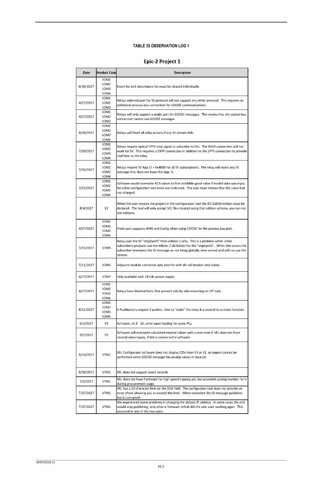
.
APPENDIX H
H-2
TABLE 35 OBSERVATION LOG 1
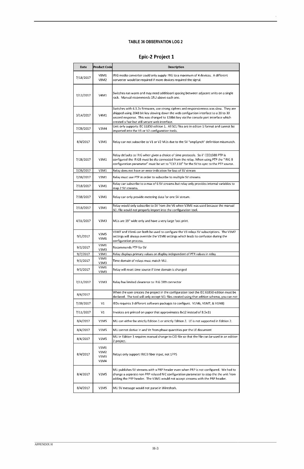
.
APPENDIX H
H-3
TABLE 36 OBSERVATION LOG 2
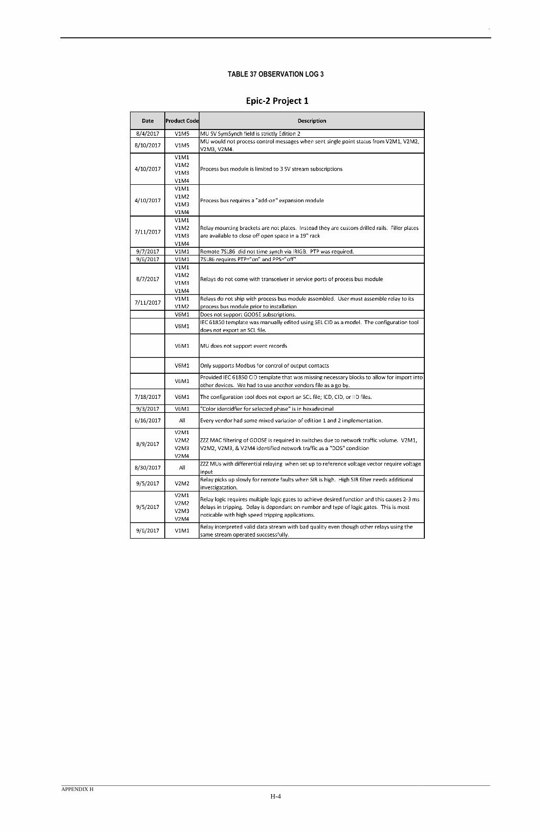
.
APPENDIX H
H-4
TABLE 37 OBSERVATION LOG 3