Embed Size (px)
Citation preview
LET’S DESIGN AN ANTENNAVK3PY
Episode 1A 40m Vertical
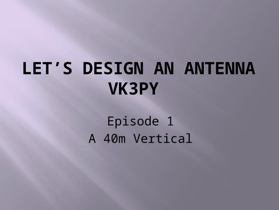
The design brief:
High efficiency (i.e. low losses) Suitable for working DX Covers the entire 40m band, preferably
without an ATU Suitable for a permanent home
installation or portable operation Fully self-contained, i.e. does not rely on
existing supports (trees etc.) Can be erected by one person Minimal space requirements
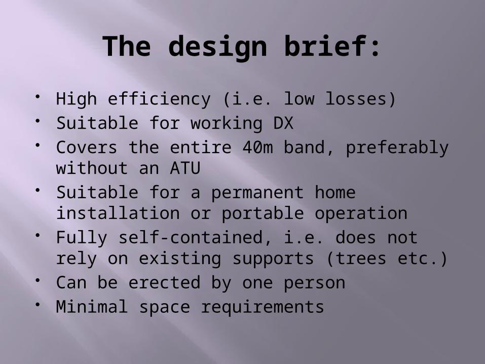
Some options:
Half-wave dipole Inverted “L” Random wire Vertical of some sort
Of these, only the vertical appears to fit all the requirements of the design brief.
Any horizontal wire antenna will require at least two supports. More significantly, at 40m a horizontal wire will have a very high angle of radiation unless it is at least half a wavelength above ground (impractical in our case).
This contravenes our design requirement of working DX
Dipole Radiation Pattern
What about a vertical then?
A full-sized quarter-wave would be about 10.5 m high.
Almost practical with a squid pole support (mine is 9.6 m high). A loading coil would be required.
Has the desired radiation pattern
Needs an extensive earth radial system (not really practical)
40m Ground mounted vertical
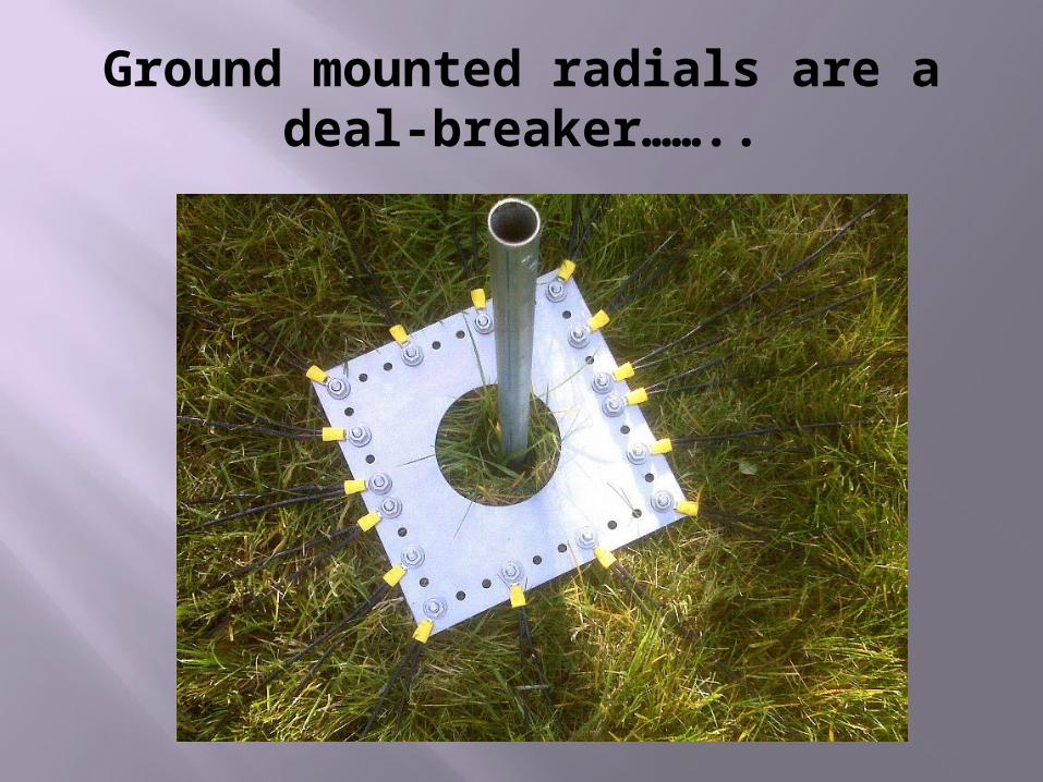
Ground mounted radials are a deal-breaker……..
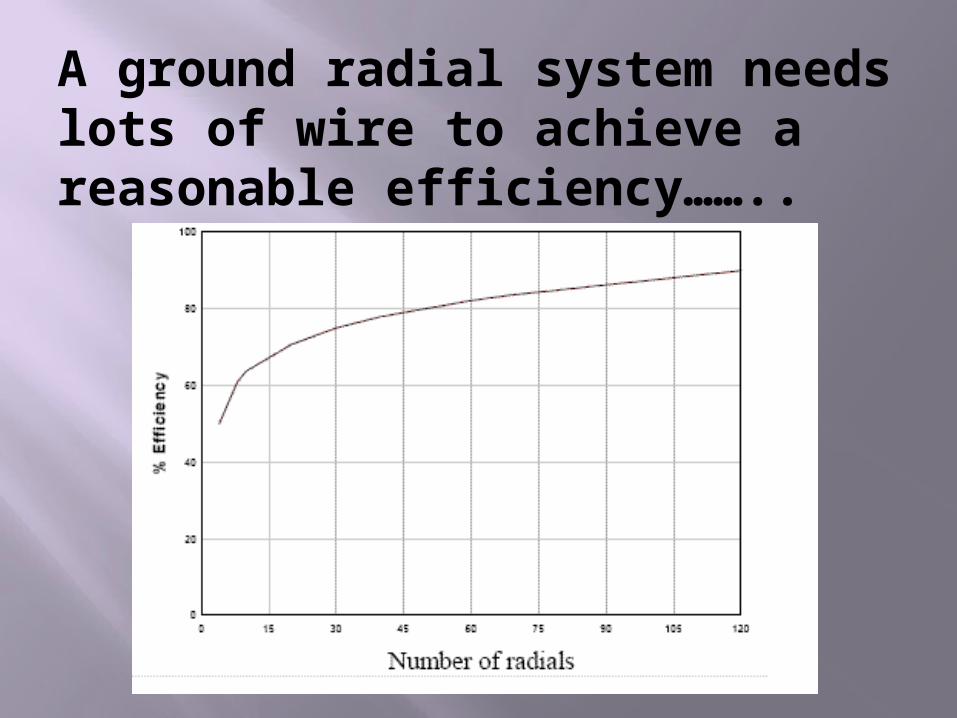
A ground radial system needs lots of wire to achieve a reasonable efficiency……..
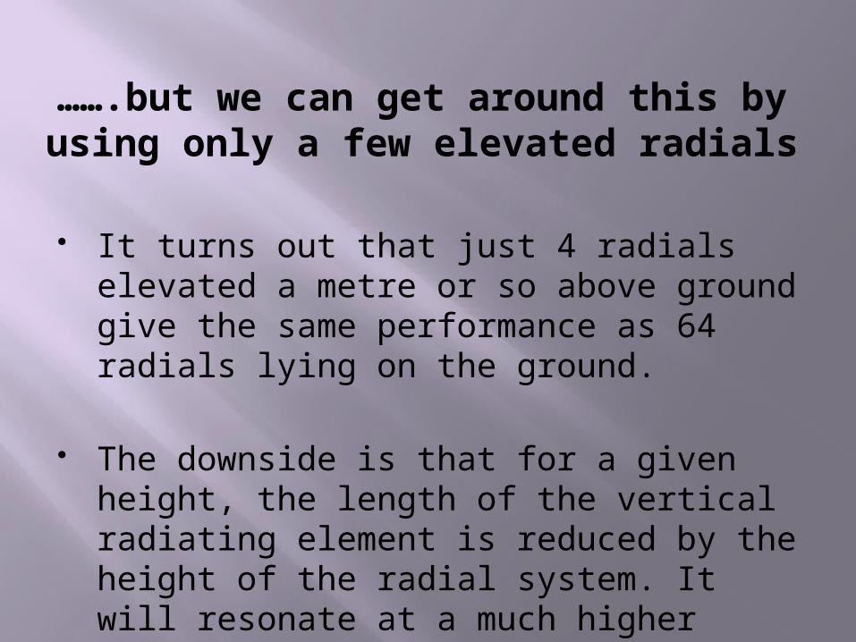
…….but we can get around this by using only a few elevated radials
It turns out that just 4 radials elevated a metre or so above ground give the same performance as 64 radials lying on the ground.
The downside is that for a given height, the length of the vertical radiating element is reduced by the height of the radial system. It will resonate at a much higher frequency.
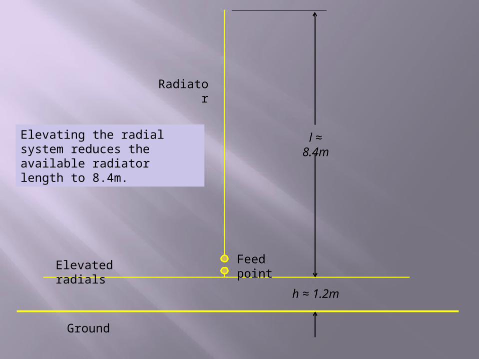
h ≈ 1.2m
l ≈ 8.4m
Elevated radials
Ground
Radiator
Feed point
Elevating the radial system reduces the available radiator length to 8.4m.
Ground
Radiator
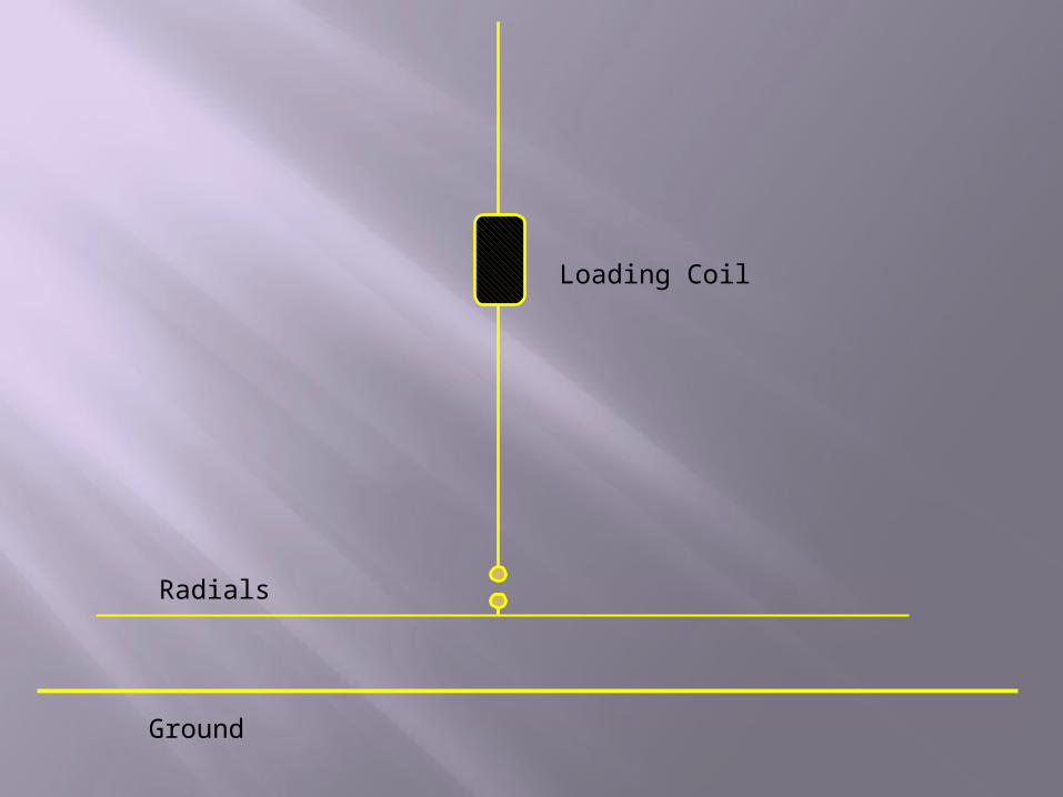
Loading Coil
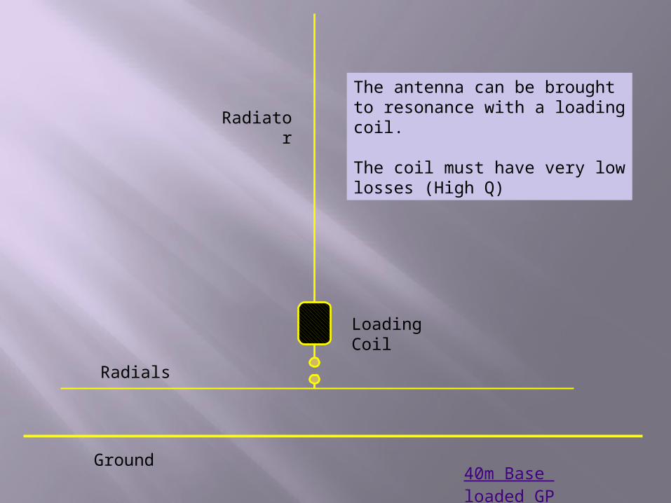
The antenna can be brought to resonance with a loading coil.
The coil must have very low losses (High Q)
40m Base loaded GP
Radials
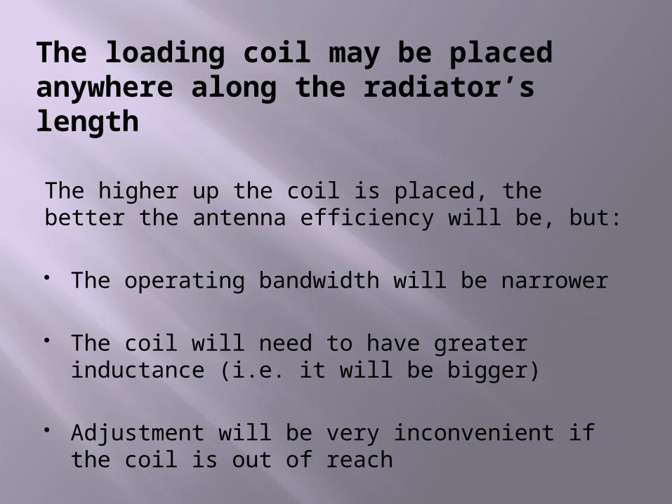
The loading coil may be placed anywhere along the radiator’s length
The higher up the coil is placed, the better the antenna efficiency will be, but:
The operating bandwidth will be narrower
The coil will need to have greater inductance (i.e. it will be bigger)
Adjustment will be very inconvenient if the coil is out of reach
Ground
Loading Coil
Radials
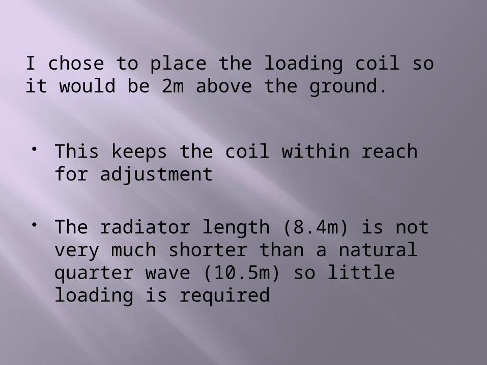
I chose to place the loading coil so it would be 2m above the ground.
This keeps the coil within reach for adjustment
The radiator length (8.4m) is not very much shorter than a natural quarter wave (10.5m) so little loading is required
But what about those radials?
Each radial is also of a resonant length (1/4 wavelength, or 10.5m)
At least four radials are required, and more would be desirable
That’s a lot of wire to put up. The radial system alone would occupy a circular area of over 21m in diameter!
Could the radials be shortened?
Indeed they can. But they would then not be resonant.
Each radial would need its own loading coil. DON’T GO THERE!
Is there another way?
But of course………
Shortening the radials has the effect of raising the antenna’s resonant frequency
Since we already need a loading coil, we can include some additional inductance to bring the entire antenna system to resonance
However, the feed point will be RF “hot”. Some means of isolating or de-coupling the transmission line will be required
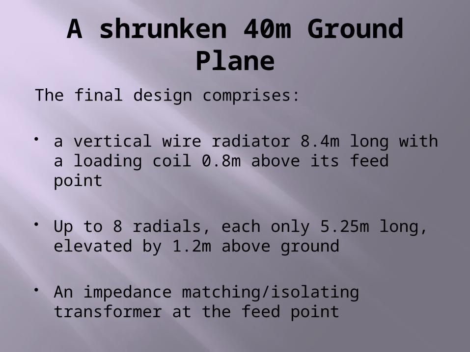
A shrunken 40m Ground Plane
The final design comprises:
a vertical wire radiator 8.4m long with a loading coil 0.8m above its feed point
Up to 8 radials, each only 5.25m long, elevated by 1.2m above ground
An impedance matching/isolating transformer at the feed point
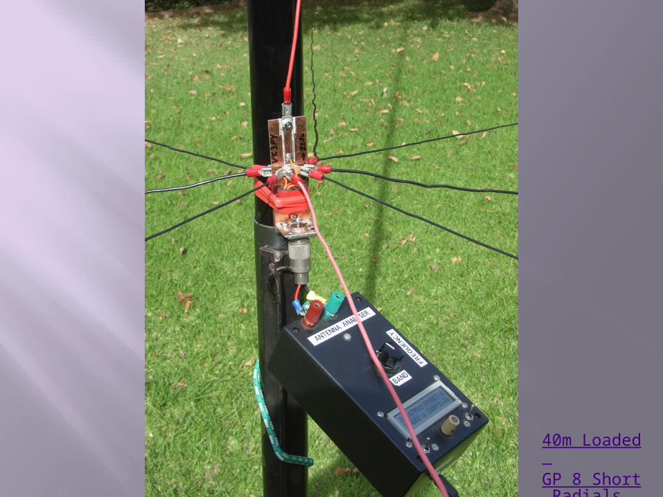
40m Loaded GP 8 Short Radials
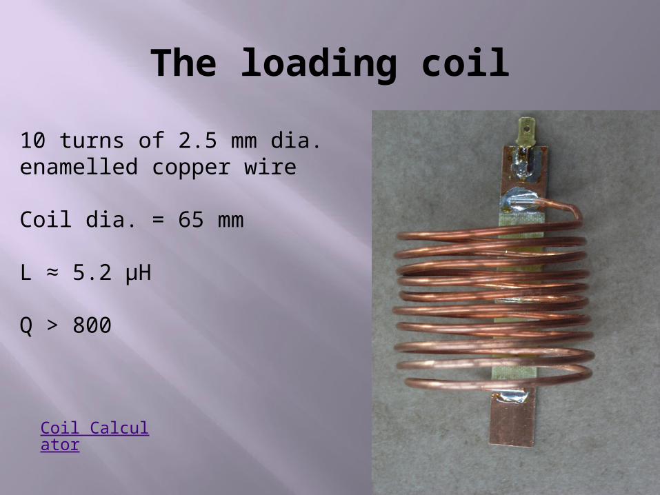
The loading coil
10 turns of 2.5 mm dia. enamelled copper wire
Coil dia. = 65 mm
L ≈ 5.2 μH
Q > 800
Coil Calculator
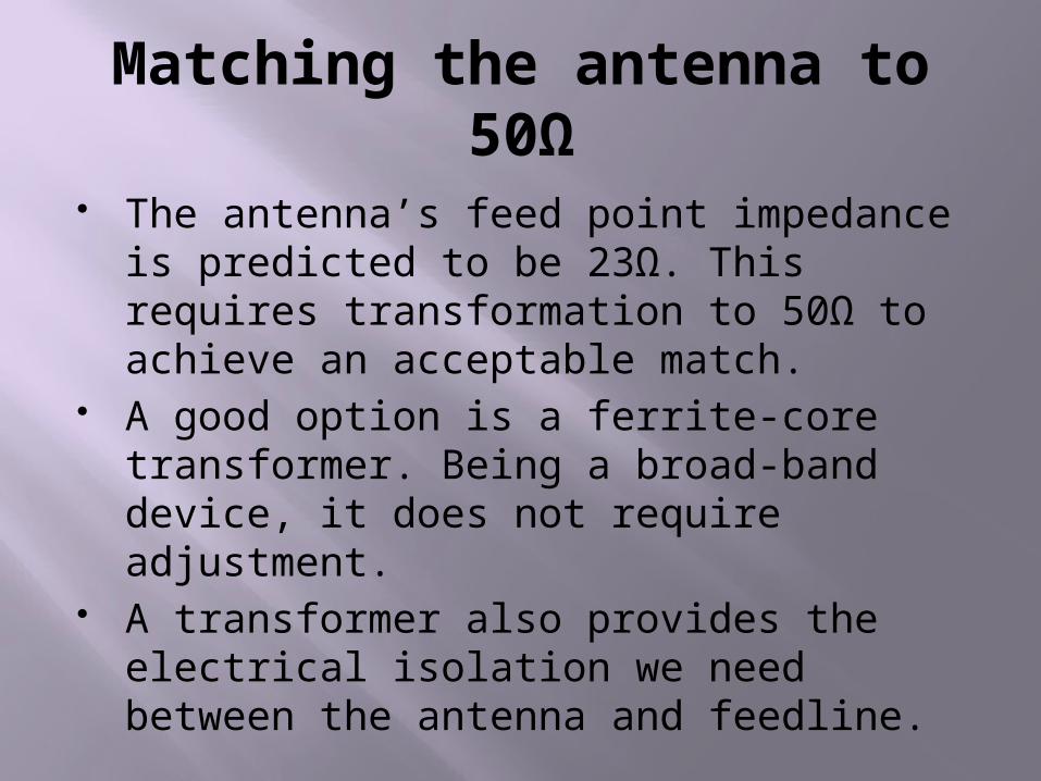
Matching the antenna to 50Ω
The antenna’s feed point impedance is predicted to be 23Ω. This requires transformation to 50Ω to achieve an acceptable match.
A good option is a ferrite-core transformer. Being a broad-band device, it does not require adjustment.
A transformer also provides the electrical isolation we need between the antenna and feedline.
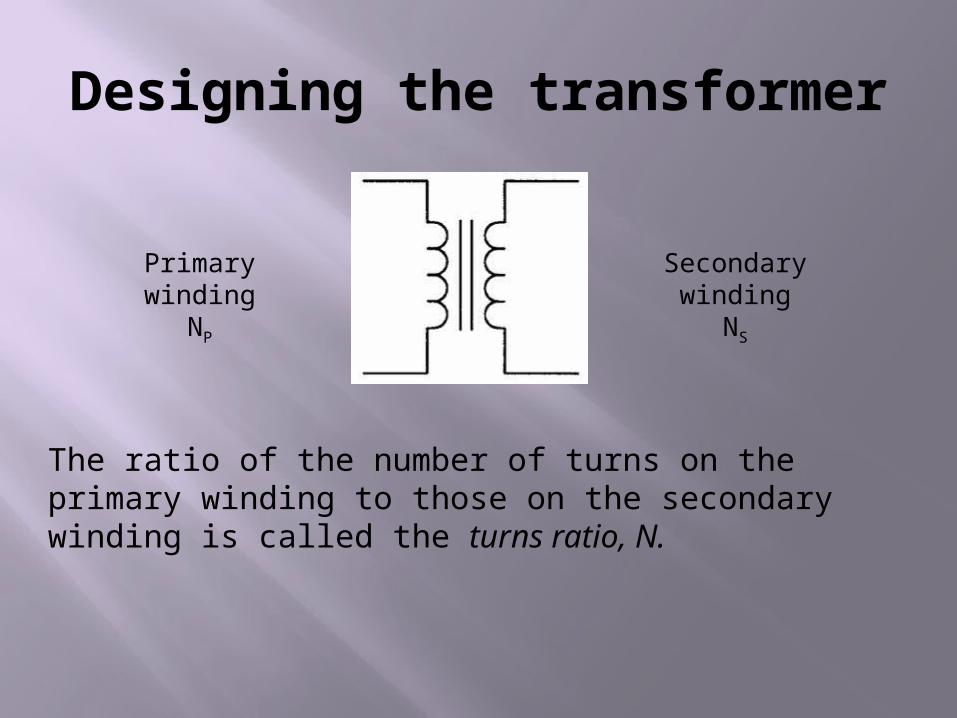
Designing the transformer
Primary windingNP
Secondary winding
NS
The ratio of the number of turns on the primary winding to those on the secondary winding is called the turns ratio, N.
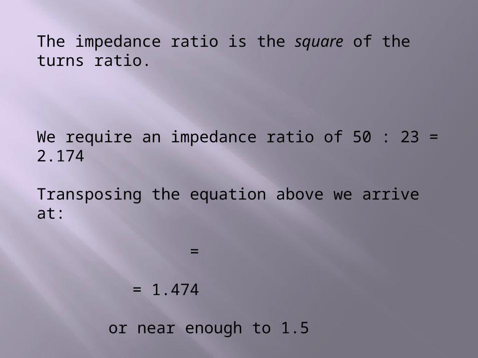
The impedance ratio is the square of the turns ratio.
We require an impedance ratio of 50 : 23 = 2.174
Transposing the equation above we arrive at:
=
= 1.474
or near enough to 1.5
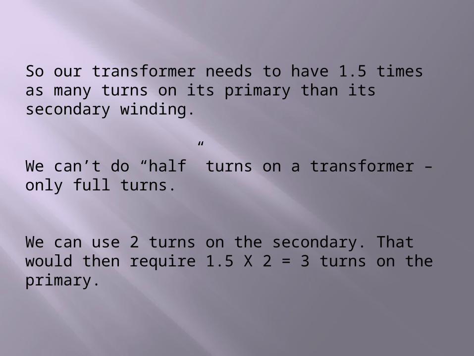
So our transformer needs to have 1.5 times as many turns on its primary than its secondary winding.
We can’t do “half” turns on a transformer – only full turns.
We can use 2 turns on the secondary. That would then require 1.5 X 2 = 3 turns on the primary.
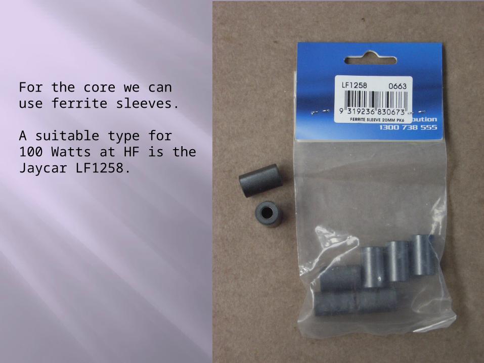
For the core we can use ferrite sleeves.
A suitable type for 100 Watts at HF is the Jaycar LF1258.
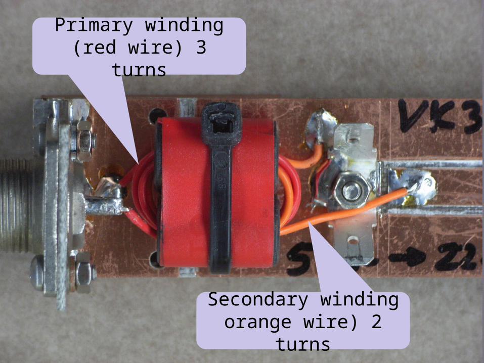
Primary winding (red wire) 3 turns
Secondary winding orange wire) 2 turns
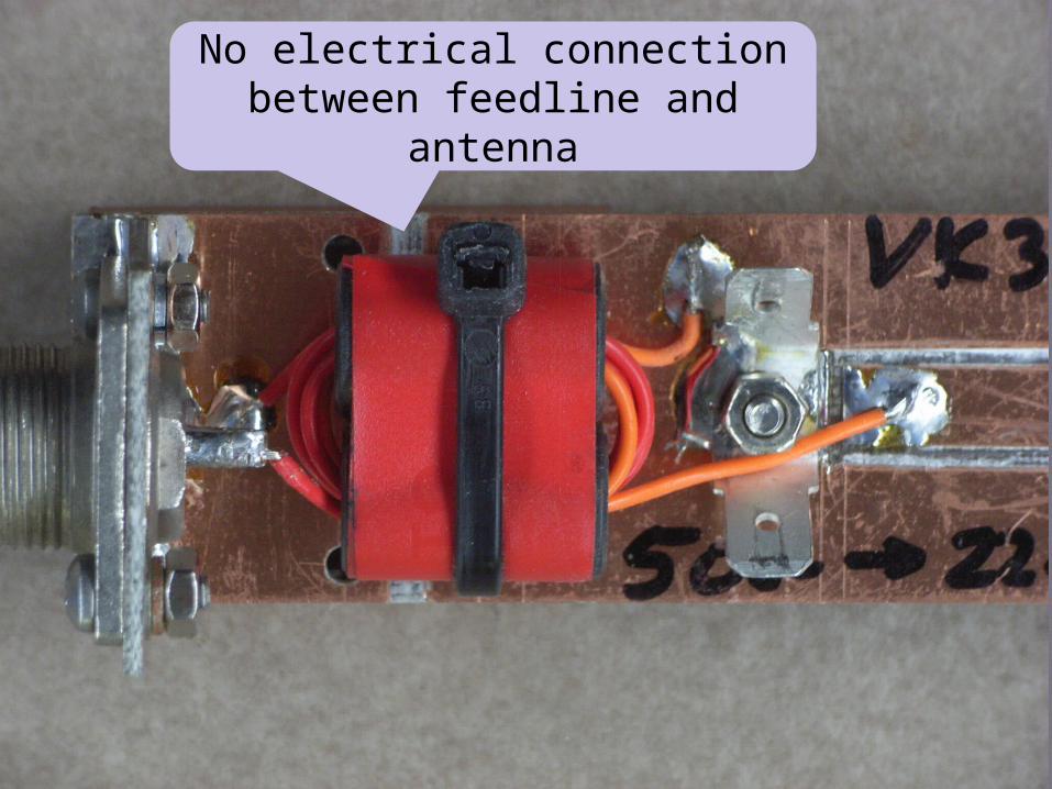
No electrical connection between feedline and
antenna
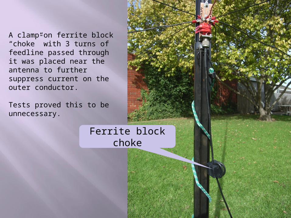
Ferrite block choke
A clamp-on ferrite block “choke” with 3 turns of feedline passed through it was placed near the antenna to further suppress current on the outer conductor.
Tests proved this to be unnecessary.
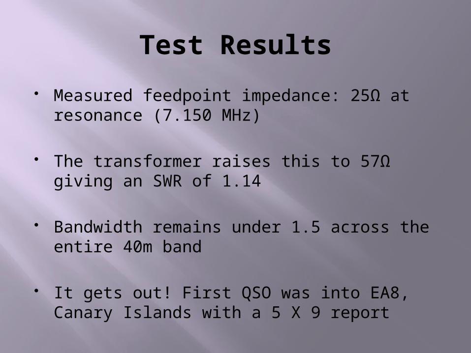
Test Results
Measured feedpoint impedance: 25Ω at resonance (7.150 MHz)
The transformer raises this to 57Ω giving an SWR of 1.14
Bandwidth remains under 1.5 across the entire 40m band
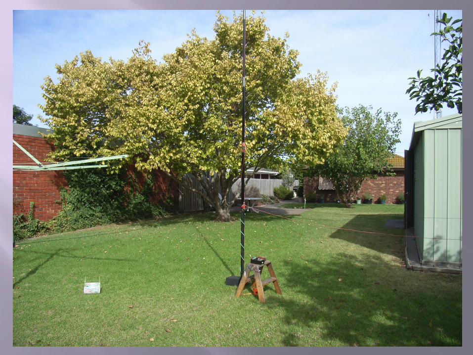
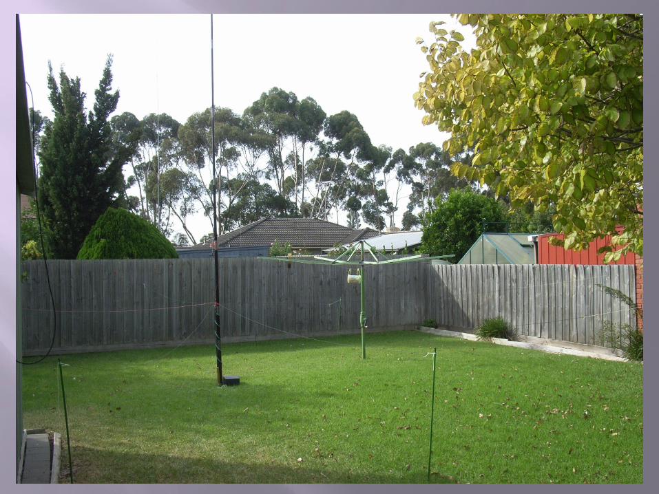
It gets out! First QSO was into EA8, Canary Islands with a 5 X 9 report
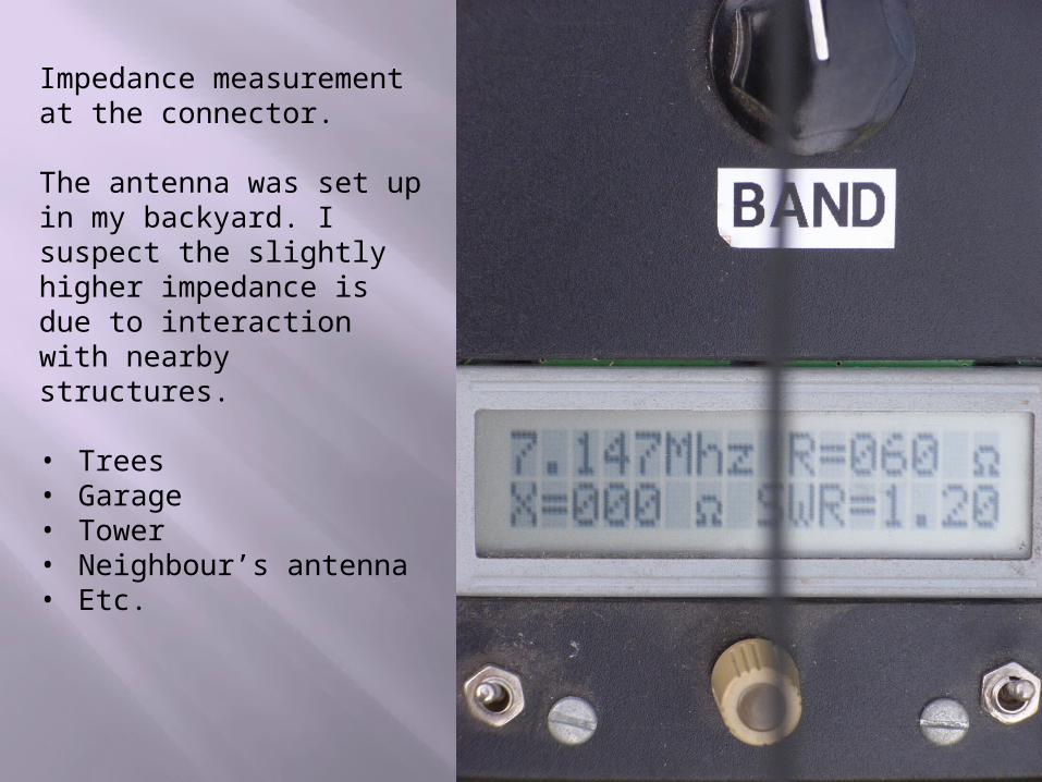
Impedance measurement at the connector.
The antenna was set up in my backyard. I suspect the slightly higher impedance is due to interaction with nearby structures.
• Trees• Garage• Tower• Neighbour’s antenna• Etc.
Homework
1. Re-design this antenna for use with an 8m long squid pole as the support
2. Modify your design to allow operation on both the 40 or 30 metre bands