Embed Size (px)
Citation preview

V2400 Series Expansion Modules User’s Manual
Third Edition, March 2011
www.moxa.com/product
© 2011 Moxa Inc. All rights reserved.

V2400 Series Expansion Modules User’s Manual
The software described in this manual is furnished under a license agreement and may be used only in accordance with the terms of that agreement.
Copyright Notice
© 2011 Moxa Inc., All rights reserved.
Trademarks
The MOXA logo is a registered trademark of Moxa Inc. All other trademarks or registered marks in this manual belong to their respective manufacturers.
Disclaimer
Information in this document is subject to change without notice and does not represent a commitment on the part of Moxa. Moxa provides this document as is, without warranty of any kind, either expressed or implied, including, but not limited to, its particular purpose. Moxa reserves the right to make improvements and/or changes to this manual, or to the products and/or the programs described in this manual, at any time. Information provided in this manual is intended to be accurate and reliable. However, Moxa assumes no responsibility for its use, or for any infringements on the rights of third parties that may result from its use. This product might include unintentional technical or typographical errors. Changes are periodically made to the information herein to correct such errors, and these changes are incorporated into new editions of the publication.
Technical Support Contact Information
www.moxa.com/support
Moxa Americas Toll-free: 1-888-669-2872 Tel: +1-714-528-6777 Fax: +1-714-528-6778
Moxa China (Shanghai office) Toll-free: 800-820-5036 Tel: +86-21-5258-9955 Fax: +86-21-5258-5505
Moxa Europe Tel: +49-89-3 70 03 99-0 Fax: +49-89-3 70 03 99-99
Moxa Asia-Pacific Tel: +886-2-8919-1230 Fax: +886-2-8919-1231

Table of Contents
1. Introduction ...................................................................................................................................... 1-1 Overview ........................................................................................................................................... 1-2 Package Checklist ............................................................................................................................... 1-2 Product Features ................................................................................................................................ 1-2 EPM Module Specifications ................................................................................................................... 1-2
EPM-3032 Specifications .............................................................................................................. 1-2 EPM-3112 Specifications .............................................................................................................. 1-3 EPM-3337 Specifications .............................................................................................................. 1-3 EPM-3438 Specifications .............................................................................................................. 1-5 EPM-3552 Specifications .............................................................................................................. 1-5
2. Hardware Introduction ..................................................................................................................... 2-1 Appearance ........................................................................................................................................ 2-2
EPM-3032 .................................................................................................................................. 2-2 EPM-3112 .................................................................................................................................. 2-2 EPM-3337 .................................................................................................................................. 2-2 EPM-3438 .................................................................................................................................. 2-2 EPM-3552 .................................................................................................................................. 2-3 EPM-DK01 .................................................................................................................................. 2-3
Dimensions ........................................................................................................................................ 2-4 3. Hardware Connection Description ..................................................................................................... 3-1
Installing the EPM Expansion Modules ................................................................................................... 3-2 Connecting Data Transmission Cables ................................................................................................... 3-3
Connecting to the EPM-3032 Serial Port Module .............................................................................. 3-3 Connecting to the EPM-3337 Wireless/GPS Module .......................................................................... 3-3 Connecting to the EPM-3438 DI/DO Module .................................................................................... 3-3 Connecting to the EPM-3112 CANbus Port Module ........................................................................... 3-4 Connecting to the EPM-DK01 Module ............................................................................................. 3-5 Connecting to the EPM-3552 Display Module ................................................................................... 3-5
4. Software Installation and Programming Guide ................................................................................. 4-1 Linux System ..................................................................................................................................... 4-2
EPM-3032 Driver Installation ........................................................................................................ 4-2 EPM-3032 Programming Guide ...................................................................................................... 4-2
Example to set the baud rate ................................................................................................ 4-2 Example to get the baud rate ................................................................................................ 4-2 Baud rate inaccuracy ............................................................................................................ 4-3 Special Note ........................................................................................................................ 4-3 Configure Serial Port Mode .................................................................................................... 4-3
EPM-3438 Driver Installation ........................................................................................................ 4-4 EPM-3438 Programming Guide ...................................................................................................... 4-5
Digital I/O ........................................................................................................................... 4-5 EPM-3337 Driver Installation ...................................................................................................... 4-14
The EPM-3337’s Two Operating Modes .................................................................................. 4-15 Normal mode—GPRS/HSDPA functionality only ...................................................................... 4-16 Multiplexer mode—GPS and GPRS/HSDPA dual functionality .................................................... 4-16 Troubleshooting for pppd .................................................................................................... 4-18 Setting up a Wireless Connection ......................................................................................... 4-19 Getting Wireless Card Information ....................................................................................... 4-20
EPM-3112 Driver Installation ...................................................................................................... 4-21 EPM-3112 Programming Guide .................................................................................................... 4-21
CANBUS Library ................................................................................................................. 4-21 Moxa functions for CANbus .......................................................................................... 4-21 Moxa definitions for CANbus ........................................................................................ 4-23
Example Code ................................................................................................................... 4-23 EPM-3552 Driver Installation ...................................................................................................... 4-23 EPM-3552 Chipset Configuration ................................................................................................. 4-24
Configuration for Displaying only on the EPM-3552 ................................................................ 4-26 Dynamically Changing the Display Resolution ........................................................................ 4-26
Windows System .............................................................................................................................. 4-26 EPM-3032 Driver Installation ...................................................................................................... 4-26 Configuring Serial Port Mode ....................................................................................................... 4-29 Changing UART Mode Through Programming ................................................................................ 4-33 EPM-3438 Driver Installation ...................................................................................................... 4-34 EPM-3438 Programming Guide .................................................................................................... 4-37
Moxa functions for DI/DO.................................................................................................... 4-37 Moxa I/O control definitions for COUNTER ............................................................................. 4-38
EPM-3337 Driver Installation ...................................................................................................... 4-39 Wireless Module Driver Installation .............................................................................................. 4-46

Configuring the GPRS/HSDPA Connection (without GPS) ................................................................ 4-53 Enabling GPS Functionality ......................................................................................................... 4-57 Configuring a Wireless Connection ............................................................................................... 4-59 Getting Wireless Module Information ........................................................................................... 4-62 EPM-3112 Driver Installation ...................................................................................................... 4-63 EPM-3112 Programming Guide .................................................................................................... 4-66
CANBUS Library ................................................................................................................. 4-66 EPM-3552 Driver Installation ...................................................................................................... 4-68 EPM-3552 Configuration ............................................................................................................. 4-70 Setting the Display to Extend Mode with the Windows Properties .................................................... 4-71
Setting the Display to Extend Mode with the DisplayLink Properties .......................................... 4-72 Setting the Display to Mirror Mode with DisplayLink Properties ................................................ 4-72 Setting the Display as the Primary Display with Windows Properties ......................................... 4-73 Disabling the Laptop Screen ................................................................................................ 4-74 Setting the Display as the Primary Display with DisplayLink Properties ..................................... 4-74
EPM-3552 Patch File Installation .................................................................................................. 4-74 Known Technical Issues ...................................................................................................... 4-74 Installing the Patch File ...................................................................................................... 4-74
A. Video Performance Table for the EPM-3552 Module .......................................................................... A-1 EPM-3552 Display Module Performance on Linux Systems ........................................................................ A-2 EPM-3552 Display Module Performance on Windows Systems ................................................................... A-3

1 1. Introduction
Moxa’s EPM series modules, which include modules with serial ports, a wireless/GPS card, a digital input/output channel card, a CANbus card, a mini PCI/PCIe card, and a VGA/DVI-I display card, work with Moxa’s V2422 and V2426 embedded computers, giving end-users the ability to set up and expand a variety of industrial applications.
The following topics are covered in this chapter:
Overview
Package Checklist
Product Features
EPM Module Specifications
EPM-3032 Specifications
EPM-3112 Specifications
EPM-3337 Specifications
EPM-3438 Specifications
EPM-3552 Specifications
V2400 Series Expansion Modules Introduction
1-2
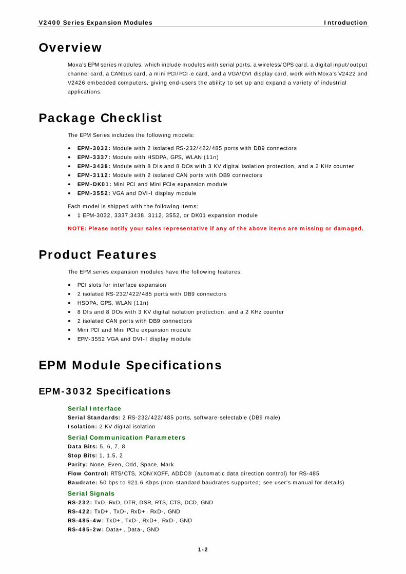
Overview Moxa’s EPM series modules, which include modules with serial ports, a wireless/GPS card, a digital input/output channel card, a CANbus card, a mini PCI/PCI-e card, and a VGA/DVI display card, work with Moxa’s V2422 and V2426 embedded computers, giving end-users the ability to set up and expand a variety of industrial applications.
Package Checklist The EPM Series includes the following models:
• EPM-3032: Module with 2 isolated RS-232/422/485 ports with DB9 connectors • EPM-3337: Module with HSDPA, GPS, WLAN (11n) • EPM-3438: Module with 8 DIs and 8 DOs with 3 KV digital isolation protection, and a 2 KHz counter • EPM-3112: Module with 2 isolated CAN ports with DB9 connectors • EPM-DK01: Mini PCI and Mini PCIe expansion module • EPM-3552: VGA and DVI-I display module
Each model is shipped with the following items: • 1 EPM-3032, 3337,3438, 3112, 3552, or DK01 expansion module
NOTE: Please notify your sales representative if any of the above items are missing or damaged.
Product Features The EPM series expansion modules have the following features:
• PCI slots for interface expansion • 2 isolated RS-232/422/485 ports with DB9 connectors • HSDPA, GPS, WLAN (11n) • 8 DIs and 8 DOs with 3 KV digital isolation protection, and a 2 KHz counter • 2 isolated CAN ports with DB9 connectors • Mini PCI and Mini PCIe expansion module • EPM-3552 VGA and DVI-I display module
EPM Module Specifications
EPM-3032 Specifications Serial Interface Serial Standards: 2 RS-232/422/485 ports, software-selectable (DB9 male) Isolation: 2 KV digital isolation
Serial Communication Parameters Data Bits: 5, 6, 7, 8 Stop Bits: 1, 1.5, 2 Parity: None, Even, Odd, Space, Mark Flow Control: RTS/CTS, XON/XOFF, ADDC® (automatic data direction control) for RS-485 Baudrate: 50 bps to 921.6 Kbps (non-standard baudrates supported; see user's manual for details)
Serial Signals RS-232: TxD, RxD, DTR, DSR, RTS, CTS, DCD, GND RS-422: TxD+, TxD-, RxD+, RxD-, GND RS-485-4w: TxD+, TxD-, RxD+, RxD-, GND RS-485-2w: Data+, Data-, GND

V2400 Series Expansion Modules Introduction
1-3
Physical Characteristics Weight: 137 g Dimensions: 104 x 121 x 34 mm (4.09 x 4.76 x 1.34 in)
Environmental Limits Operating Temperature: -40 to 70°C (-40 to 158°F)
EPM-3112 Specifications CANbus Communication Interface: 2 optically isolated CAN2.0A/2.0B compliant ports CAN Controller: Phillips SJA1000T Signals: CAN-H, CAN-L Isolation: 2 KV digital isolation Speed: 1 Mbps Connector Type: DB9 male
Physical Characteristics Weight: 127 g Dimensions: 104 x 121 x 34 mm (4.09 x 4.76 x 1.34 in)
Environmental Limits Operating Temperature: -25 to 55°C (-13 to 131°F)
EPM-3337 Specifications Cellular Interface Frequency Bands: • UMTS/HSDPA: Triple band, 850/1900/1900 MHz • GSM/GPRS/EDGE: Quad band, 850/900/1800/2100 MHz • GSM Dass: Small MS Output Power: • Class 4 (2 W) for GSM850/900 • Class 3 (0.25 W) for UMTS/HSDPA • Class E2 (0.5 W) for EDGE850/900 • Class E2 (0.4 W) for EDGE1800/1900 • Class 1 (1 W) for GSM1800/1900
HSDPA Interface 3GPP Release 5: • 3.6 Mbps, UL 384 Kbps • UE CAT. [1-6], 11, 12 supported • Compressed mode (CM) supported according to 3GPP TS25.212
GPS Interface Tracking: Tracks up to 13 satellites, L1 1575.42 MHz Accuracy Position: 2.5 m CEP; 5.0 m SEP Protocols: NMEA-0183 V2.3, E911 AGPS Control plane, GPS dedicated AT commands, Date WGS-84 Tracking sensitivity: -158 dBm (with active antenna) Start-up Time: • Hot start: <3s • Cold start: 30s • Warm start: 30s GPS active antenna supply: 3.3 V

V2400 Series Expansion Modules Introduction
1-4
WLAN Interface Supported Modes: • IEEE 802.11a/b/g/n for client/bridge mode • IEEE 802.11b/g/n for AP mode (Linux OS only) Standards: • IEEE 802.11a/b/g/n for Wireless LAN • IEEE 802.11i for Wireless Security Operating Channels (central frequency): • US: 2.412 to 2.462 GHz (11 channels), 5.18 to 5.24 GHz (4 channels) • EU: 2.412 to 2.472 GHz (13 channels), 5.18 to 5.24 GHz (4 channels) • USA: 1 to 11 (2400 to 2483.5 MHz) • Europe: 1 to 13 (2400 to 2483.5 MHz) • Japan: 1 to 14 (2400 to 2497 MHz) 802.11g: • USA: 1 to 11 (2400 to 2483.5 MHz) • Europe: 1 to 13 (2400 to 2483.5 MHz) • Japan: 1 to 13 (2400 to 2497 MHz) 802.11a: • USA: 36 to 165 (5180 to 5825 MHZ) • Europe: 36 140 (5180 to 5700 MHz) • Japan: 7 to 11 (5035 to 5055MHz),183 to 189 (4915 to 4945 MHz) Security: 64-bit and 128-bit WEP encryption, WPA /WPA2-Personal and Enterprise (IEEE 802.1X/RADIUS, TKIP and AES) Transmission Rates: • 802.11b: 1, 2, 5.5, 11 Mbps • 802.11a/g: 6, 9, 12, 18, 24, 36, 48, 54 Mbps • 802.11n: 6 to 300 Mbps (multiple rates supported) TX Transmit Power: • 802.11b: 1 to 11 Mbps: Typ. 18 dBm (± 1.5 dBm) • 802.11g: 6 to 24 Mbps: Typ. 18 dBm (± 1.5 dBm); 36 to 48 Mbps: Typ. 17 dBm (± 1.5 dBm); 54 Mbps: Typ. 15 dBm (± 1.5 dBm) • 802.11a: 6 to 24 Mbps: Typ. 17 dBm (± 1.5 dBm) 36 to 48 Mbps: Typ. 16 dBm (± 1.5 dBm); 54 Mbps: Typ. 14 dBm (± 1.5 dBm) TX Transmit Power MIMO: • 802.11a/n (20/40 MHz): MCS15 20 MHz: Typ. 13 dBm (± 1.5 dBm); MCS15 40 MHz: Typ. 12 dBm (± 1.5 dBm) • 802.11g/n (20/40 MHz): MCS15 20 MHz: Typ. 14 dBm (± 1.5 dBm); MCS15 40 MHz: Typ. 13 dBm (± -1.5 dBm) RX Sensitivity: • 802.11b: -92 dBm @ 1 Mbps, -90 dBm @ 2 Mbps, -88 dBm @ 5.5 Mbps, -84 dBm @ 11 Mbps • 802.11g: -87 dBm @ 6 Mbps, -86 dBm @ 9 Mbps, -85 dBm @ 12 Mbps, -82 dBm @ 18 Mbps, -80 dBm @ 24 Mbps, -76 dBm @ 36 Mbps, -72 dBm @ 48 Mbps, -70 dBm @ 54 Mbps • 802.11a: -87 dBm @ 6 Mbps, -86 dBm @ 9 Mbps, -85 dBm @ 12 Mbps, -82 dBm @ 18 Mbps, -80 dBm @ 24 Mbps, -76 dBm @ 36 Mbps, -72 dBm @ 48 Mbps, -70 dBm @ 54 Mbps RX Sensitivity MIMO: • 802.11a/n: -68 dBm @ MCS15 40 MHz, -70 dBm @ MCS7 40 MHz, -69 dBm @ MCS15 20 MHz, -71 dBm @ MCS7 20 MHz • 802.11g/n: -68 dBm @ MCS15 40 MHz, -70 dBm @ MCS7 40 MHz, -69 dBm @ MCS15 20 MHz, -71 dBm @ MCS7 20 MHz

V2400 Series Expansion Modules Introduction
1-5
AP-only Protocols: ARP, BOOTP, DHCP, dynamic VLAN-Tags for 802.1X-Clients, STP/RSTP (IEEE 802.1D/w) Default Antenna: 2 dBi dual-band omni-directional antenna, RP-SMA (male) Connector for External Antennas: RP-SMA (female)
Physical Characteristics Weight: 220 g Dimensions: 104 x 121 x 34 mm (4.09 x 4.76 x 1.34 in)
Environmental Limits Operating Temperature: -25 to 55°C (-13 to 131°F), EN 50155 Class T1
EPM-3438 Specifications Digital Input Input Channels: 8, source type Input Voltage: 0 to 30 VDC at 25 Hz Digital Input Levels for Dry Contacts: • Logic level 0: Close to GND • Logic level 1: Open Digital Input Levels for Wet Contacts: • Logic level 0: +3 V max. • Logic level 1: +10 V to +30 V (Source to DI) Counter Frequency: 2 KHz (DI0 only) Connector Type: 10-pin screw terminal block (8 DI points, DI Source, GND) Isolation: 3 KV optical isolation
Digital Output Output Channels: 8, sink type, 0 to 30 VDC Output Current: Max. 200 mA per channel On-state Voltage: 24 VDC nominal, open collector to 30 VDC Connector Type: 9-pin screw terminal block (8 DO points, GND) Isolation: 3 KV optical isolation
Physical Characteristics Weight: 120 g Dimensions: 104 x 121 x 34 mm (4.09 x 4.76 x 1.34 in)
Environmental Limits Operating Temperature: -40 to 70°C (-40 to 158°F), EN 50155 Class TX
EPM-3552 Specifications Display Graphics Controller: DsiplayLink DL-195 VGA Interface: 15-pin D-sub connector (female) DVI Interface: 24-pin DVI-I connector (female) Resolution: Up to 1920x 1600 (2048 x 1152 for wide screen) resolution
Physical Characteristics Weight: 130 g Dimensions: 104 x 121 x 34 mm (4.09 x 4.76 x 1.34 in)
Environmental Limits Operating Temperature: -25 to 55°C (-13 to 131°F)

2 2. Hardware Introduction
The EPM Series expansion modules are designed to work with Moxa’s V2422 and V2426 embedded computers. By providing different modules with different connectors, the EPM series offers the greatest flexibility and convenience for users who would like to easily establish industrial applications that require different communication interfaces.
The following topics are covered in this chapter:
Appearance
EPM-3032
EPM-3112
EPM-3337
EPM-3438
EPM-3552
EPM-DK01
Dimensions

V2400 Series Expansion Modules Hardware Introduction
2-2
Appearance
EPM-3032
EPM-3112
EPM-3337
EPM-3438

V2400 Series Expansion Modules Hardware Introduction
2-3
EPM-3552
EPM-DK01

V2400 Series Expansion Modules Hardware Introduction
2-4
Dimensions

3 3. Hardware Connection Description
In this chapter, we show how to connect the embedded computers to the network and to various devices.
The following topics are covered in this chapter:
Installing the EPM Expansion Modules
Connecting Data Transmission Cables
Connecting to the EPM-3032 Serial Port Module
Connecting to the EPM-3337 Wireless/GPS Module
Connecting to the EPM-3438 DI/DO Module
Connecting to the EPM-3112 CANbus Port Module
Connecting to the EPM-DK01 Module
Connecting to the EPM-3552 Display Module
V2400 Series Expansion Modules Hardware Connection Description
3-2
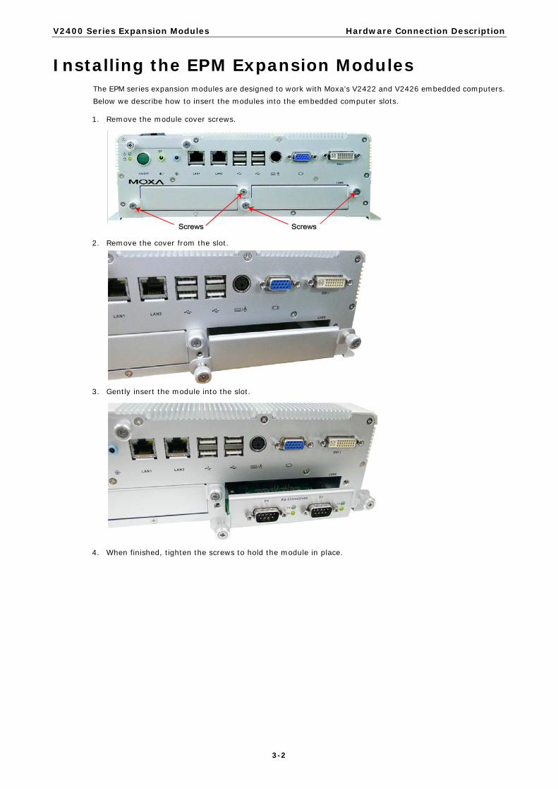
Installing the EPM Expansion Modules The EPM series expansion modules are designed to work with Moxa’s V2422 and V2426 embedded computers. Below we describe how to insert the modules into the embedded computer slots.
1. Remove the module cover screws.
2. Remove the cover from the slot.
3. Gently insert the module into the slot.
4. When finished, tighten the screws to hold the module in place.

V2400 Series Expansion Modules Hardware Connection Description
3-3
Connecting Data Transmission Cables In this section we explain how to connect the EPM modules to devices.
Connecting to the EPM-3032 Serial Port Module Use a serial cable to plug your serial device into the module’s serial port. Serial ports 1 and 2 have male DB9 connectors and can be configured for RS-232, RS-422, or RS-485 communication by software. The pin assignments are shown in the following table:
DB9 Male Port RS-232/422/485 Pinouts
Pin RS-232 RS-422 RS-485 (4-wire)
RS-485 (2-wire)
1 DCD TxDA(-) TxDA(-) –
2 RxD TxDB(+) TxDB(+) –
3 TxD RxDB(+) RxDB(+) DataB(+)
4 DTR RxDA(-) RxDA(-) DataA(-)
5 GND GND GND GND
6 DSR – – –
7 RTS – – –
8 CTS – – –
Connecting to the EPM-3337 Wireless/GPS Module The EPM-3337 module comes with 4 connectors that can be used to connect antennas, including 2 WiFi antennas, 1 cellular antenna, and 1 GPS antenna. Refer to the following figure for the location of the different antennas.
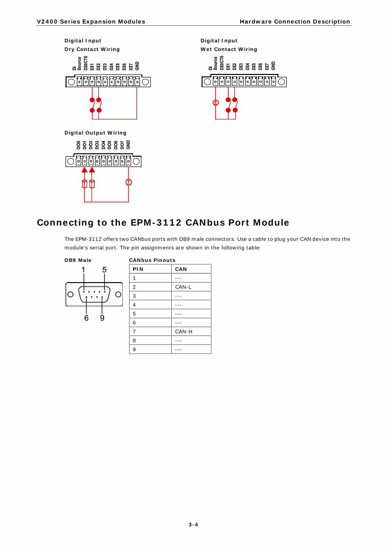
Connecting to the EPM-3438 DI/DO Module The EPM-3438 module comes with 8 digital input channels and 8 digital output channels. See the following figures for pin definitions and wiring methods.
V2400 Series Expansion Modules Hardware Connection Description
3-4
Digital Input Dry Contact Wiring
Digital Input Wet Contact Wiring
Digital Output Wiring
Connecting to the EPM-3112 CANbus Port Module The EPM-3112 offers two CANbus ports with DB9 male connectors. Use a cable to plug your CAN device into the module’s serial port. The pin assignments are shown in the following table:
DB9 Male CANbus Pinouts
PIN CAN 1 ---
2 CAN-L
3 ---
4 ---
5 ---
6 ---
7 CAN-H
8 ---
9 ---

V2400 Series Expansion Modules Hardware Connection Description
3-5
Connecting to the EPM-DK01 Module The EPM-DK01 offers a mini-PCI and a mini-PCIe sockets, allowing users to insert a mini-PCI or a mini-PCIe card. See the following figure for the specific locations when installing these cards. Meanwhile, if you need to connect the antenna, use the connectors on the exterior panel.
Connecting to the EPM-3552 Display Module The EPM-3552 display modules comes with a VGA connector and a DVI-I connector. Use a cable to connect the display to the connector on the module.
The pin assignments are shown in the following tables.

V2400 Series Expansion Modules Hardware Connection Description
3-6
D-Sub 15 Connector Pin Assignments
Pin No. Signal Definitions 1 RED
2 GREEN
3 BLUE
4 –
5 GND
6 CRT_DETECT#
7 GND
8 GND
9 +5V
10 GND
11 –
12 DDC_DATA
13 HSYNC
14 VSYNC
15 –
DVI-I Connector Pin Assignments
Pin No. Signal Definition
1 T.M.D.S. Data2-
2 T.M.D.S. Data2+
3 T.M.D.S. Data2/4 Shield
4 T.M.D.S. Data4-
5 T.M.D.S. Data4-
6 DDC Clock
7 DDC Data
8 Analog Vertical Sync
9 T.M.D.S. Data1-
10 T.M.D.S. Data1+
11 T.M.D.S. Data1/3 Shield
12 T.M.D.S. Data3-
13 T.M.D.S. Data3+
14 +5V Power
15 Ground (return for +5V, HSync, and VSync)
16 Hot Plug Detect
17 T.M.D.S. Data0-
18 T.M.D.S. Data0+
19 T.M.D.S. Data0/5 Shield
20 T.M.D.S. Data5-
21 T.M.D.S. Data5+
22 T.M.D.S. Clock Shield
23 T.M.D.S. Clock+
24 T.M.D.S. Clock-
C1 Analog Red
C2 Analog Green
C3 Analog Blue
C4 Analog Horizontal Sync
C5 Analog Ground (analog R, G, B return)

4 4. Software Installation and Programming
Guide
In this chapter we discuss software installation and programming guide for the EPM-3032, EPM-3337, and EPM-3438 expansion modules.
The following topics are covered in this chapter:
Linux System
EPM-3032 Driver Installation
EPM-3032 Programming Guide
EPM-3438 Driver Installation
EPM-3438 Programming Guide
EPM-3337 Driver Installation
EPM-3112 Driver Installation
EPM-3112 Programming Guide
EPM-3552 Driver Installation
EPM-3552 Chipset Configuration
Windows System
EPM-3032 Driver Installation
Configuring Serial Port Mode
Changing UART Mode Through Programming
EPM-3438 Driver Installation
EPM-3438 Programming Guide
EPM-3337 Driver Installation
Wireless Module Driver Installation
Configuring the GPRS/HSDPA Connection (without GPS)
Enabling GPS Functionality
Configuring a Wireless Connection
Getting Wireless Module Information
EPM-3112 Driver Installation
EPM-3112 Programming Guide
EPM-3552 Driver Installation
EPM-3552 Configuration
Setting the Display to Extend Mode with the Windows Properties
EPM-3552 Patch File Installation

V2400 Series Expansion Modules Software Installation and Programming Guide
4-2
Linux System
EPM-3032 Driver Installation The EPM-3032 supports Linux standard termios control. The normal tty device node is located at /dev/ttyM8, ttyM9. /dev/ttyM16 and ttyM17 are the second device files for the EPM-3032 module. The Moxa UART Device API allows you to configure ttyMx for RS-232, RS-422, 4-wire RS-485, or 2-wire RS-485.
The EPM-3032 driver has been pre-installed at the following location, and will be loaded automatically when the system boots up.
Moxa:~# /lib/modules/2.6.30-bpo.2-686/kernel/drivers/char/mxser.ko
EPM-3032 Programming Guide
Example to set the baud rate
#define MOXA 0x400
#define MOXA_SET_SPECIAL_BAUD_RATE (MOXA+100)
#define MOXA_GET_SPECIAL_BAUD_RATE (MOXA+101)
#include <termios.h>
struct termios term;
int fd, speed;
fd = open(“/dev/ttyM8”, O_RDWR);
tcgetattr(fd, &term);
term.c_cflag &= ~(CBAUD | CBAUDEX);
term.c_cflag |= B4000000;
tcsetattr(fd, TCSANOW, &term);
speed = 115200;
ioctl(fd, MOXA_SET_SPECIAL_BAUD_RATE, &speed);
Example to get the baud rate
#define MOXA 0x400
#define MOXA_SET_SPECIAL_BAUD_RATE (MOXA+100)
#define MOXA_GET_SPECIAL_BAUD_RATE (MOXA+101)
#include <termios.h>
struct termios term;
int fd, speed;
fd = open(“/dev/ttyM8”, O_RDWR);
tcgetattr(fd, &term);
if ( (term.c_cflag & (CBAUD|CBAUDEX)) != B4000000 ) {
// follow the standard termios baud rate define
} else {
ioctl(fd, MOXA_GET_SPECIAL_BAUD_RATE, &speed);
}

V2400 Series Expansion Modules Software Installation and Programming Guide
4-3
Baud rate inaccuracy
Divisor = 921600/Target Baud Rate. (Only Integer part)
ENUM = 8 * (921600/Targer - Divisor) ( Round up or down)
Inaccuracy = (Target Baud Rate – 921600/(Divisor + (ENUM/8))) * 100%
E.g.,
To calculate 500000 bps
Divisor = 1, ENUM = 7,
Inaccuracy = 1.7%
*For reliable performance, inaccuracy should be under 2%
Special Note
The embedded serial ports do not support special baud rates and the maximum baud rate is only 115200 bps. However, the expansion board can support special baud rates and maximum baud rates of up to 921600 bps.
If the target baud rate is not a special baud rate (e.g. 50, 75, 110, 134, 150, 200, 300, 600, 1200, 1800, 2400, 4800, 9600, 19200, 38400, 57600, 115200, 230400, 460800, 921600), the termios cflag will be set to the same flag.
If you use stty to get the serial information, you will get speed equal to 0.
Configure Serial Port Mode
Use “setinterface” command to retrieve the parameters of the serial port configuration.
Moxa:~# setinterface
Usage: setinterface device-node [interface-no]
device-node - /dev/ttyMn; n = 0,1,2,...
interface-no - following:
none - to view now setting
0 - set to RS232 interface
1 - set to RS485-2WIRES interface
2 - set to RS422 interface
3 - set to RS485-4WIRES interface
Moxa:~#
The different serial modes use specific parameters.
1 – set to RS485-2WIRES interface
2 – set to RS422 interface
3 – set to RS485-4WIRES interface
To check the current interface setting:
Moxa: ~# setinterface /dev/ttyM8
Now setting is RS485-2WIRES interface.
In this case, Serial Port 1 is set as RS-485 2-wire. (M0 refers to port 1, and M1 refers to port 2, and so on)
To change the current interface setting:
Moxa: ~# setinterface /dev/ttyM8 2
Moxa: ~# setinterface /dev/ttyM8
Now setting is RS422 interface.
In this case, Serial Port 1 has been changed and is set as RS-422 mode.
To load the settings as the Default Value:

V2400 Series Expansion Modules Software Installation and Programming Guide
4-4
When OS boots up, the default interface mode of the EPM-3032 is RS232. If you want to change the default interface mode, please use the following steps:
First remount the read-only root file system in writable mode.
Moxa:~# mount -o remount,rw /dev/hda1 /
Moxa:~#
Next, edit /etc/udev/rules.d/96-moxa.rules. Add the following description to 96-moxa.rules. The VendorID of the EPM-3032 must be 0x1393and the DeviceID must be 0x1022. For example:
# Set the device, EPM-3032, 0x1393:0x1022 default as 232 mode interface
DRIVERS=="mxser", ATTRS{vendor}=="0x1393", ATTRS{device}=="0x1022",
RUN+="/bin/setinterface /dev/ttyM%n 0"
"96-moxa.rules"
Edit the command line RUN+="/bin/setinterface /dev/ttyM%n 0”.
If you want to set the serial mode to RS-232, use the following parameter.
RUN+="/bin/setinterface /dev/ttyM%n 0"
If you want to set the serial mode to RS-485 2-wire, use the following parameter.
RUN+="/bin/setinterface /dev/ttyM%n 1"
If you want to set the serial mode to RS-422, use the following parameter.
RUN+="/bin/setinterface /dev/ttyM%n 2"
If you want to set the serial mode to RS-485 4-wire, use the following parameter.
RUN+="/bin/setinterface /dev/ttyM%n 3"
When finished, remember to umount the writable root file system.
Moxa:~# umount /
Moxa:~#
Reboot your computer.
Moxa:~# reboot
Moxa:~#
Once the computer restarts, confirm that the setting has been loaded as the default value.
Moxa:~# setinterface /dev/ttyM8
Now setting is RS485-2WIRES interface.
Moxa:~#
EPM-3438 Driver Installation Upload the package to embedded computer and to the tmpfs, /dev/shm.
root:~# scp epm3438-2.6.30-bpo.2-686.deb [email protected]:/dev/shm
root:~#
Install the package
Moxa:~# cd /dev/shm
Moxa:~# mount -o remount,rw /
Moxa:~# dpkg -i ./epm3438-2.6.30-bpo.2-686.de
Moxa:~# umount /
After the driver installs, you can use lsmod to check if the epm3438 module is loaded in the kernel.

V2400 Series Expansion Modules Software Installation and Programming Guide
4-5
Moxa:~# lsmod|more
Module Size Used by
epm3438 4620 0
…
In /etc/init.d/moxainit.sh will add the `modprobe epm3438` and `modprobe -r epm3438` lines.
Moxa:~# vi /etc/init.d/moxainit.sh
…
start)
…
modprobe moxa_device_dio device="v2400"
modprobe mxser
modprobe epm3438
…
;;
stop)
…
modprobe -r epm3438
modprobe -r moxa_swtd
modprobe -r moxa-device-dio
;;
...
If you need to uninstall the driver, you can use this command:
Moxa:~# mount -o remount,rw /
Moxa:~# dpkg -r epm3438
Moxa:~# umount /
EPM-3438 Programming Guide
Digital I/O
Digital input/output channels are featured in some models of Moxa embedded computers, including the UC-7408, UC-8410, IA240, IA260, W406 and EPM-3438. These channels can be accessed at run-time for control or monitoring using the functions in the following sections. Digital Output channels can be set to high or low via each port starting from 0. The Digital Input channels can be used to detect the state change of the digital input signal. The header file of digital I/O functions is mxdgio.h, which is located in the digit_input_change directory for Linux.
Moxa functions for DI/DO
Function HANDLE mxdgio_epm3438_open(int HWIndex); Description This function opens access to the DIO device.
Input <HWIndex> The first or second EPM-3438 board.
Output None
Return When successful, this function returns an access to the DIO device. Otherwise, there is an error.
Function void mxdgio_close(HANDLE fd); Description This function closes the access to the DIO device.
Input <fd> The access to the device.
Output None
Return None

V2400 Series Expansion Modules Software Installation and Programming Guide
4-6
Function int mxdgio_get_input_signal(HANDLE fd, int port);
Description This function gets the signal state of a digital input channel.
Input <fd> The access to the device. <port> port #
Output <state> DIO_HIGH (1) for high, DIO_LOW (0) for low
Return Returns 1 for a high signal or 0 for a low signal, if successful. Otherwise, it returns a value of -1.
Function int mxdgio_get_output_signal(HANDLE fd, int port);
Description This function gets the signal state of a digital output channel.
Input <fd> The access to the device. <port> Port number
Output None
Return Returns 1 for a high signal or 0 for a low signal, if successful. Otherwise, it returns a value of -1.
Function int mxdgio_set_output_signal_high(HANDLE fd, int port);
Description This function sets a high signal to a digital output channel.
Input <fd> The access to the device. <port> Port number.
Output none.
Return When successful, this function returns 0. When an error occurs, it returns -1.
Function int mxdgio_set_output_signal_low(HANDLE fd, int port);
Description This function sets a low signal to a digital output.
Input <fd> The access to the device. <port> Port number.
Output none.
Return When successful, this function returns 0. When an error occurs, it returns -1.
Moxa I/O control definitions for COUNTER #define COUNTER_NODE1 "/dev/epm_3438_counter1" #define COUNTER_NODE2 "/dev/epm_3438_counter2"
Function int mxdgio_epm3438_get_counter(int fd); Description get the counter value
Input <fd> The access to the counter device. <port> Port number.
Output none.
Return the counter value
Function int mxdgio_epm3438_clear_counter(int fd); Description Clear the counter value
Input <fd> The access to the counter device. <port> Port number.
Output none.
Return 0:clear success; -n: clear fail

V2400 Series Expansion Modules Software Installation and Programming Guide
4-7
Special Note 1. We have provided an example in CD digit_input_change. The mxdgio.h defines the convenient API for
DIO and COUNTER programming. 2. The DO initial status is HIGH. If you want the initial DO status to be LOW, you should add one line in
/etc/modules to load epm_3438.ko with epm3438_DO2LOW=1;
Moxa: ~# modinfo /lib/modules/2.6.30-bpo.2-686/kernel/drivers/char/epm_3438.ko
filename: /lib/modules/2.6.30-bpo.2-686/kernel/drivers/char/epm_3438.ko
description: EPM-3438: DIO/Counter module
author: [email protected]
license: GPL
depends:
vermagic: 2.6.30-bpo.2-686 SMP mod_unload modversions 686
parm: epm3438_DO2LOW:Reset DO to LOW. 0. Set DO to High (default). 1. Set DO
to LOW. (int)
Moxa: ~# mount -o remount,rw /
Moxa: ~# vi /etc/init.d/moxainit.sh
…
# Load the EPM-3438 DIO driver.
modprobe epm_3438 epm3438_DO2LOW=1
…
Moxa: ~# umount /
This DIO sample program shows how users can develop a set of higher layer functions using preliminary DIO
functions from the peripheral I/O library. These functions allow user applications to focus on event handling
when events occur. A callback function is defined by the programmer to associate with an event. The source
code files of the sample program are located in the samples/mxphio/digit_input_change directory for Linux
Four higher layer functions, digit_io_timer_init, digit_io_timer_dispatch,
digit_io_timer_add_callback, and digit_io_timer_dispatch_quit, are provided. Four callback functions
in the sample are added for four different events: DGTIO_GET_INPUT_STATE_CHANGE,
DGTIO_GET_INPUT, DGTIO_GET_OUTPUT, and DGTIO_SET_OUTPUT, via the
digit_io_timer_add_callback function.
mngr = digit_io_timer_init();
…
if (digit_io_timer_add_callback(mngr, HWIndex, port, DGTIO_GET_INPUT_STATE_CHANGE, interval, input_chg_cb, &port) < 0) {
…
}
if (digit_io_timer_add_callback(mngr, HWIndex, port, DGTIO_GET_INPUT, interval, input_get_cb, &port) < 0) {
…
}

V2400 Series Expansion Modules Software Installation and Programming Guide
4-8
if (digit_io_timer_add_callback(mngr, HWIndex, port, DGTIO_SET_OUTPUT, interval, output_set_cb, &port) < 0) {
…
}
if (digit_io_timer_add_callback(mngr, HWIndex, port, DGTIO_GET_OUTPUT, interval, output_get_cb, &port) < 0) {
…
}
digit_io_timer_dispatch(mngr);
Examples
DIO Program Source Code File Example
File and Folder: digit_input_change/digit_io_timer.c
Description: Routines to operate timer functions on digital IO port.
#include <stdio.h>
#include <stdlib.h>
#if !defined(_WIN32_WCE) && !defined(WIN32)
#include <time.h>
#endif
#include "digit_io_timer.h"
/* callback function */
static void
dgio_input_change_exec(DGIOMNGR *mngr, DGIOITEM *item)
{
int sig;
HANDLE fd=mngr->fd[item->HWIndex];
switch(item->mode)
{
case DGTIO_GET_INPUT:
sig = mxdgio_get_input_signal(fd, item->port);
item->cb(item->HWIndex, item->port, sig, item->arg);
break;
case DGTIO_GET_OUTPUT:
sig = mxdgio_get_output_signal(fd, item->port);
item->cb(item->HWIndex, item->port, sig, item->arg);
break;
case DGTIO_GET_INPUT_STATE_CHANGE:
sig = mxdgio_get_input_signal(fd, item->port);
if (item->last_signal!=sig)
{
item->cb(item->HWIndex, item->port, sig, item->arg);
}
break;
case DGTIO_SET_OUTPUT:
sig = item->cb(item->HWIndex, item->port, item->last_signal, item->arg);
if (sig)
{
mxdgio_set_output_signal_high(fd, item->port);
}
else
{

V2400 Series Expansion Modules Software Installation and Programming Guide
4-9
mxdgio_set_output_signal_low(fd, item->port);
}
break;
default:
return;
}
item->last_signal = sig;
}
/* release the timer operation
*/
static void
dgio_input_change_release(DGIOMNGR *mngr)
{
int i;
DGIOITEM *item, *next;
item=mngr->list;
while(item)
{
next = item->next;
free(item);
item = next;
}
for ( i=0; i<HW_TOTAL; i++ )
if (mngr->fd[i])
mxdgio_close(mngr->fd[i]);
}
/* this function initilizes a timer manager
Returns:
Return a pointer to the manager.
*/
DGIOMNGR*
digit_io_timer_init(void)
{
DGIOMNGR *mngr;
mngr = (DGIOMNGR*) calloc(1, sizeof(DGIOMNGR));
if (mngr)
{
mngr->fd[0] = mxdgio_open();
#if 1 // Jared, 08-10-2010, support the second EPM-3438
mngr->fd[1] = mxdgio_epm3438_open(0); // The first EPM-3438
mngr->fd[2] = mxdgio_epm3438_open(1); // The second EPM-3438
#endif
if (mngr->fd[0] < 0)
{
free(mngr);
mngr = NULL;
}
}
return mngr;
}
/* add a digital io timer with a selected operation mode
Inputs:
<mngr> timer manager
<HWIndex> specify which hardware device;
0: embedded DIO, 1: EPM-3438 #1, 2: EPM-3438 #2

V2400 Series Expansion Modules Software Installation and Programming Guide
4-10
<port> specify which DIO pin
<mode> the operation mode on the port
<interval> the interval (in milliseconds) between 2 calls to a user-defined
function
<cb> the user-defined callback function
<arg> argument to the function
Returns:
0 on sucess, otherwise failure
*/
int
digit_io_timer_add_callback(DGIOMNGR *mngr, int HWIndex, int port, int mode, int
interval, digit_io_cb_t cb, void *arg)
{
DGIOITEM *item;
item = (DGIOITEM*) calloc (1, sizeof (DGIOITEM));
if (!item)
return -1;
item->next = mngr->list;
mngr->list = item;
item->cb = cb;
item->arg = arg;
item->HWIndex = HWIndex; // Jared, 08-10-2010, HWIndex to support multiple boards
item->port = port;
item->mode = mode;
item->interval = interval;
item->next_time = interval;
// Jared, 08-10-2010, HWIndex to support multiple boards
item->last_signal = mxdgio_get_input_signal(mngr->fd[HWIndex], port);
return 0;
}
void
digit_io_timer_dispatch_quit(DGIOMNGR *mngr)
{
if (mngr) mngr->dispatch = 0;
}
#define MAX_TIME 0XFFFFFFFF
/* start and dispatch the timer operations
Inputs:
<mngr> the manager
Returns:
none
*/
void
digit_io_timer_dispatch(DGIOMNGR *mngr)
{
DGIOITEM *item;
unsigned int ms_sleep, n;
#if !defined(_WIN32_WCE) && !defined(WIN32)
struct timeval to;
#endif
mngr->dispatch = 1;
while(mngr->list && mngr->dispatch)
{
for (item = mngr->list; item != NULL; item = item->next)
{

V2400 Series Expansion Modules Software Installation and Programming Guide
4-11
if (mngr->now_time < item->next_time) /* not yet */
continue;
n = mngr->now_time - item->next_time;
/* over due, executable */
item->next_time = mngr->now_time+item->interval-n; /* move to the next
time */
dgio_input_change_exec(mngr, item);
}
ms_sleep = MAX_TIME;
/* get the amount of time to sleep */
for (item = mngr->list; item != NULL; item = item->next)
{
if (mngr->now_time < item->next_time) /* not yet */
{
n = item->next_time - mngr->now_time;
if (n < ms_sleep) ms_sleep = n;
continue;
}
}
if (ms_sleep!=MAX_TIME)
{
#if !defined(_WIN32_WCE) && !defined(WIN32)
to.tv_sec = ms_sleep/1000;
to.tv_usec = (ms_sleep%1000)*1000;
if (select (0, NULL, NULL, 0, &to) != 0) /* sleep */
break;
#else
Sleep(ms_sleep);
#endif
mngr->now_time += ms_sleep;
}
}
dgio_input_change_release(mngr);
}
File and Folder: digit_input_change/main.c
Description: This program is an example to operate timer functions on digital IO ports.
#include <stdio.h>
#include <stdlib.h>
#include "digit_io_timer.h"
static int
input_chg_cb(int HWIndex, int port, int sig, void *arg)
{
printf("input_chg_cb() HWIndex %d port %d sig %d\n", HWIndex, port, sig);
return 0;
}
static int
input_get_cb(int HWIndex, int port, int sig, void *arg)
{
printf("input_get_cb() HWIndex %d port %d sig %d\n", HWIndex, port, sig);
return 0;
}
static int
output_set_cb(int HWIndex, int port, int last_sig, void *arg)
{
V2400 Series Expansion Modules Software Installation and Programming Guide
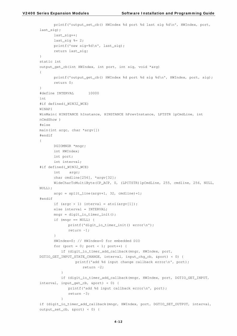
4-12
printf("output_set_cb() HWIndex %d port %d last sig %d\n", HWIndex, port,
last_sig);
last_sig++;
last_sig %= 2;
printf("new sig=%d\n", last_sig);
return last_sig;
}
static int
output_get_cb(int HWIndex, int port, int sig, void *arg)
{
printf("output_get_cb() HWIndex %d port %d sig %d\n", HWIndex, port, sig);
return 0;
}
#define INTERVAL 10000
int
#if defined(_WIN32_WCE)
WINAPI
WinMain( HINSTANCE hInstance, HINSTANCE hPrevInstance, LPTSTR lpCmdLine, int
nCmdShow )
#else
main(int argc, char *argv[])
#endif
{
DGIOMNGR *mngr;
int HWIndex;
int port;
int interval;
#if defined(_WIN32_WCE)
int argc;
char cmdline[256], *argv[32];
WideCharToMultiByte(CP_ACP, 0, (LPCTSTR)lpCmdLine, 255, cmdline, 256, NULL,
NULL);
argc = split_line(argv+1, 32, cmdline)+1;
#endif
if (argc > 1) interval = atoi(argv[1]);
else interval = INTERVAL;
mngr = digit_io_timer_init();
if (mngr == NULL) {
printf("digit_io_timer_init() error\n");
return -1;
}
HWIndex=0; // HWIndex=0 for embedded DIO
for (port = 0; port < 1; port++) {
if (digit_io_timer_add_callback(mngr, HWIndex, port,
DGTIO_GET_INPUT_STATE_CHANGE, interval, input_chg_cb, &port) < 0) {
printf("add %d input change callback error\n", port);
return -2;
}
if (digit_io_timer_add_callback(mngr, HWIndex, port, DGTIO_GET_INPUT,
interval, input_get_cb, &port) < 0) {
printf("add %d input callback error\n", port);
return -3;
}
if (digit_io_timer_add_callback(mngr, HWIndex, port, DGTIO_SET_OUTPUT, interval,
output_set_cb, &port) < 0) {

V2400 Series Expansion Modules Software Installation and Programming Guide
4-13
printf("add %d set output callback error\n", port);
return -4;
}
if (digit_io_timer_add_callback(mngr, HWIndex, port, DGTIO_GET_OUTPUT, interval,
output_get_cb, &port) < 0) {
printf("add %d get output callback error\n", port);
return -5;
}
}
/ / HWIndex=1 for EPM-3438 board #1; HWIndex=2, for EPM-3438 board #2
for (HWIndex = 0; HWIndex < HW_TOTAL; HWIndex++ ) {
for (port = 0; port < 8; port++) {
/* since list is LIFO last callbacks are added first */
if (digit_io_timer_add_callback(mngr, HWIndex, port, DGTIO_GET_INPUT_STATE_CHANGE,
interval, input_chg_cb, &port) < 0) {
printf("add %d input change callback error\n", port);
return -2;
}
if (digit_io_timer_add_callback(mngr, HWIndex, port, DGTIO_GET_INPUT, interval,
input_get_cb, &port) < 0) {
printf("add %d input callback error\n", port);
return -3;
}
if (digit_io_timer_add_callback(mngr, HWIndex, port, DGTIO_SET_OUTPUT, interval,
output_set_cb, &port) < 0) {
printf("add %d set output callback error\n", port);
return -4;
}
if (digit_io_timer_add_callback(mngr, HWIndex, port, DGTIO_GET_OUTPUT, interval,
output_get_cb, &port) < 0) {
printf("add %d get output callback error\n", port);
return -5;
}
}
}
digit_io_timer_dispatch(mngr);
return 0;
}
Examples
Counter Program Source Code File Example
File and Folder: digit_input_change/tcounter.c
Description: This file is an example of the EPM-3438 couter programming.
read the counter value.
read the counter value and clear the counter.
#include <stdio.h>
#include <stdlib.h>
#include <sys/time.h>
#include <fcntl.h>
#include <unistd.h>
#include <signal.h>
#include “mxdgio.h” // For counter reading or clear
#define COUNTER_NODE1 "/dev/epm_3438_counter1" // The first EPM-3438
#define COUNTER_NODE2 "/dev/epm_3438_counter2" // The second EPM-3438
int main(int argc, char * argv[])
{

V2400 Series Expansion Modules Software Installation and Programming Guide
4-14
int retval;
int fd, fd2, len;
unsigned int counter_value;
fd=open(COUNTER_NODE1, O_RDONLY);
while( 1 ) {
printf("\nSelect a number of menu, other key to exit. \n\
1. Get counter value \n\
2. Clear the counter \n\
Others. quit \n\
Choose : ");
scanf("%d", &retval);
if ( retval == 1 ) { // Get counter without reset
counter_value = mxdgio_epm3438_get_counter(fd);
printf("EPM-3438 board #1 counter:%d\n", counter_value);
}
else if ( retval == 2 ) { // Get counter with reset
retval = mxdgio_epm3438_clear_counter(fd);
if ( retval < 0 )
printf("EPM-3438 board #1 counter reset fail\n");
}
else {
break;
}
}
close(fd);
return 0;
}
EPM-3337 Driver Installation Moxa’s EPM-3337 module supports both 3G/GPS and wireless functionality. This section introduces how to configure these functions in the Linux platform.
1. Make root file system writable
2. Install the file epm3337.deb
3. Setup 3G module to Mdm mode
EPM-3337’s 3G module supports multiple modes, issue lsusb to get information: • 0681:0040 - MdmNet mode (the default factory setting)
• 0681:0047 - Mdm mode (for Linux)
Now convert EPM-3337 module with the moxa_hc25_setup_mdm.sh script at /home
Confirm that the conversion is completed
Note: You only need to do this conversion once.
Moxa:/home# lsusb
Bus 001 Device 010: ID 0681:0047 Siemens Information and Communication
Moxa:/home# sh moxa_hc25_setup_mdm.sh
Moxa:/home# dpkg -i epm3337.deb
Moxa:~# mount -o remount,rw /

V2400 Series Expansion Modules Software Installation and Programming Guide
4-15
4. Configure the driver to load at startup The default run-level is 2 (setup in /etc/inittab). Issue the following command
Note: You need to reboot to load the driver or issue /etc/init.d/moxa_hc25_load_driver
5. Install software from internet for wireless functionality
6. Create the correct links for wpa_supplicant
7. Mount root file system (/) as read-only
8. Reboot your device to complete installation
ATTENTION
ppp 2.4.4 may get the incorrect DNS after connection; here are two workaround solutions: 1. Assign the DNS manually
Comment the option “usepeerdns”in /dev/pppt/chtgprs. Then assign a DNS /etc/resolv.conf manually.
2. Remove ppp 2.4.4 and install ppp-2.4.5.deb
The EPM-3337’s Two Operating Modes
The EPM-3337 module has two modes:
1. Normal Mode: Supports only GPRS/HSDPA functionality (without GPS). The allocation of ports is: • Modem port: /dev/ttyACM0 • Command port: /dev/ttyUSB0
2. Multiplexer Mode: Supports both GPRS/HSDPA and GPS functionality. A multiplexer program must be run to put the module into multiplexer mode. The allocation of ports is: • Modem port: /dev/pts/0 • Command port: /dev/pts/1 • GPS port: /dev/pts/2
Note: If you do not need the GPS functionality, use normal mode for better performance.
Moxa:~# apt-get remove ppp
Moxa:/home# dpkg -i ppp-2.4.5.deb
#usepeerdns # use the DNS servers from the remote network
Moxa:~# umount /
Moxa:/etc/network/if-up.d# ln -sf /etc/wpa_supplicant/ifupdown.sh
wpasupplicant
Moxa:/etc/network/if-down.d# ln -sf /etc/wpa_supplicant/ifupdown.sh
wpasupplicant
Moxa:/etc/network/if-pre-up.d# ln -sf /etc/wpa_supplicant/ifupdown.sh
wpasupplicant
Moxa:/etc/network/if-post-down.d#ln -sf
/etc/wpa_supplicant/ifupdown.sh wpasupplicant
Moxa:/home# apt-get install wpasupplicant wireless-tools
Moxa:/etc/rc2.d# mv N98moxa hc25 load driver

V2400 Series Expansion Modules Software Installation and Programming Guide
4-16
Normal mode—GPRS/HSDPA functionality only
This section illustrates how to establish a connection with pppd configuration. The example files used are listed below:
• /etc/ppp/peers/chtgprs: a pppd additional option file • /etc/chatscripts/chtgprs-connect: chat file for connection • /etc/chatscripts/chtgprs-disconnect: chat file for disconnection
Take the following steps to set up your pppd:
1. Configure the file /etc/ppp/peers/chtgprs. a. First, check if the name of the modem port is correct. It should be /dev/ttyACM0 for the first module,
/dev/ttyACM1 for the second one, and so on. b. Make sure the “local” option is enabled. This option ignores the CD (Carries Detect) signal.
2. Configure /etc/chatscripts/chtgprs-connect. a. First, check the packet data protocol type and Access point name of the ISP;
a basic command is AT+CGDCONT=1,”<packet_data_protocal_type>”, “<APN>” b. Check the ATD dialout number;
a basic command is ATD<number> 3. Read configuration file to connect.
a. pppd call chtgprs 4. Finally, examine connection state.
a. If the connection is ok, a device ppp0 (or pppn) is established. Issue the command ifconfig ppp0 to view its information.
Multiplexer mode—GPS and GPRS/HSDPA dual functionality
GPS functionality is only enabled in the module’s multiplexer mode. In multiplexer mode, the system uses a pseudo terminal slave (pts) instead of reading serial ports (/dev/ttyACMx) to communicate.
This section describes how to set up GPS functionality, work with the gpsd daemon, and change the pppd configuration file for modem port /dev/pts/0.
The following steps illustrate how to set up GPS and use gpsd:
1. Set the module to multiplexer mode at startup
Note: If you insert two EPM-3337 modules, you can set module_num=2 in /etc/init.d/moxa_hc25_mux_script
2. Reboot the embedded computer. 3. The multiplexer will now automatically start at bootup. It will occupy a modem port, /dev/ttyACM0, and
generate three virtual terminal ports.
/dev/pts/0: Modem port /dev/pts/1: Command port /dev/pts/2: GPS port
Moxa:~# ls /dev/pts/
0 1 2 ptmx
Moxa:/etc/rc2.d# mv N99moxa_hc25_mux_script S99moxa_hc25_mux_script

V2400 Series Expansion Modules Software Installation and Programming Guide
4-17
NOTE 1. The command port in multiplexer mode only accepts AT commands with the suffix \r\n (i.e., carriage return and new line). You can see the echo example in “Enable GPS port by issuing command,” or set the terminal output flag with command stty -F /dev/pts/1 opost onlcr. The option onlcr translates newline to carriage return+newline.
2. For the second EPM-3337 module, the allocation will be /dev/pts/3: Modem port /dev/pts/4: Command port /dev/pts/5: GPS port
ATTENTION
The number assigned to pts is affected by remote log in programs (e.g., ssh or telnet). Therefore, it is advisable to perform moxa_hc25_mux at startup to make sure the pts number is 0 to 2. If there is more than 1 EPM-3337 module, the number of pts increases to 3 to 5, and so on.
4. Enable the GPS port by issuing a command to the command port.
5. Check for NMEA data from the GPS port (/dev/pts/2)
6. Install gpsd daemon.
7. Start gpsd to read NMEA data from the GPS port (/dev/pts/2).
8. On the remote computer, use ssh to connect to Moxa’s embedded computer and issue the cgps command.
You will see the following information:
If cgps gets non-null data from gpsd, it will display the following message:
Moxa:~# cgps
Moxa:~# gpsd /dev/pts/2
Moxa:~# apt-get install gpsd
Moxa:~# cat < /dev/pts/2
$GPGSV,1,1,04,24,28,123,37,21,09,054,31,19,52,213,,23,47,270,*74
$GPGGA,061824.0,2458.835139,N,12133.055835,E,1,05,19.7,-103.5,M,,,,*1
4
$GPRMC,061824.0,A,2458.835139,N,12133.055835,E,,,290710,,,A*68
$GPGSA,A,3,24,21,06,31,16,,,,,,,,,25.5,19.7,18.5*29
$GPVTG,,T,,M,0.0,N,0.0,K*4E
Moxa:~# cat < /dev/pts/1 &
Moxa:~# echo -e "AT^SGPSS=4\r"> /dev/pts/1
Moxa:~# killall cat

V2400 Series Expansion Modules Software Installation and Programming Guide
4-18
NOTE You can issue AT^SGPSS=0 to the command port to stop GPS information.
ATTENTION
View the following reference for more information about gpsd.
• man gpsd • man cgps • http://gpsd.berlios.de/
As described in this section, in multiplex mode the modem port is dev/pts/0 instead of /dev/ttyACM0. Check that the modem port is /dev/pts/0 at /etc/ppp/peers/chtgprs.
Now you can connect GPRS/HSDPA through pppd
Troubleshooting for pppd
To troubleshoot pppd connection problems, open /etc/ppp/peers/chtgprs and then take the following steps:
• Enable the debug option and logfile /var/ppp.log option. • Add the -V option in /usr/sbin/chat.
See /var/ppp.log for a more detailed message.
#Debug option---
#You call tail -f /var/ppp.log &
debug
logfile /var/ppp.log
connect "/usr/sbin/chat -v -V -f /etc/chatscripts/chtgprs-connect"
Moxa:~# pppd call chtgprs
# See /etc/ppp/option for detail
/dev/pts/0 # modem port used
115200 # speed
Moxa:~# cat < /dev/pts/1 &
Moxa:~# echo -e "AT^SGPSS=0\r"> /dev/pts/1
Moxa:~# killall cat

V2400 Series Expansion Modules Software Installation and Programming Guide
4-19
Setting up a Wireless Connection
In this section we introduce how to connect to an access point with WEP/WPA/WPA2(RSN) encryption. The connection program is wpa_supplicant.
The basic command is wpa_supplicant -i <interface> -c <configuration file> -B (the -B: option forces it to run in the background).
1. Example 1: Connect to AP (SSID: test_wep) with WEP key 1234567890(hex) a. Write a configure file test_wep.conf as below
b. Connect with the following commands:
wpa_supplicant -i wlan0 -c test_wep.conf -B c. Use iwconfig to check the connection state
2. Example 2: Connect to AP (SSID: test_wpa) with WPA key “1234567890” (ascii)
a. Write a configuration file test_wpa_wpa2.conf, as shown below:
b. Connect with the following command: wpa_supplicant -i wlan0 -c test_wpa_wpa2.conf –B c. Use iwconfig to check the connection state:
network={
ssid="test_wpa"
key_mgmt=WPA-PSK
proto=WPA RSN
pairwise=TKIP CCMP
group=TKIP CCMP
psk="1234567890"
}
wlan0 IEEE 802.11abgn ESSID:"test_wep"
Mode:Managed Frequency:2.462 GHz Access Point:
00:1F:1F:8C:0F:64
Bit Rate=36 Mb/s Tx-Power=27 dBm
Retry min limit:7 RTS thr:off Fragment thr:off
Encryption key:1234-5678-90 Security mode:open
Power Management:off
Link Quality=37/70 Signal level=-73 dBm
Rx invalid nwid:0 Rx invalid crypt:0 Rx invalid frag:0
Tx excessive retries:0 Invalid misc:0 Missed beacon:0
network={
ssid="test_wep"
key_mgmt=NONE
wep_key0=1234567890
wep_key1="abcde"
wep_key2="1234567890123"
wep_tx_keyidx=0
priority=5
}
V2400 Series Expansion Modules Software Installation and Programming Guide
4-20
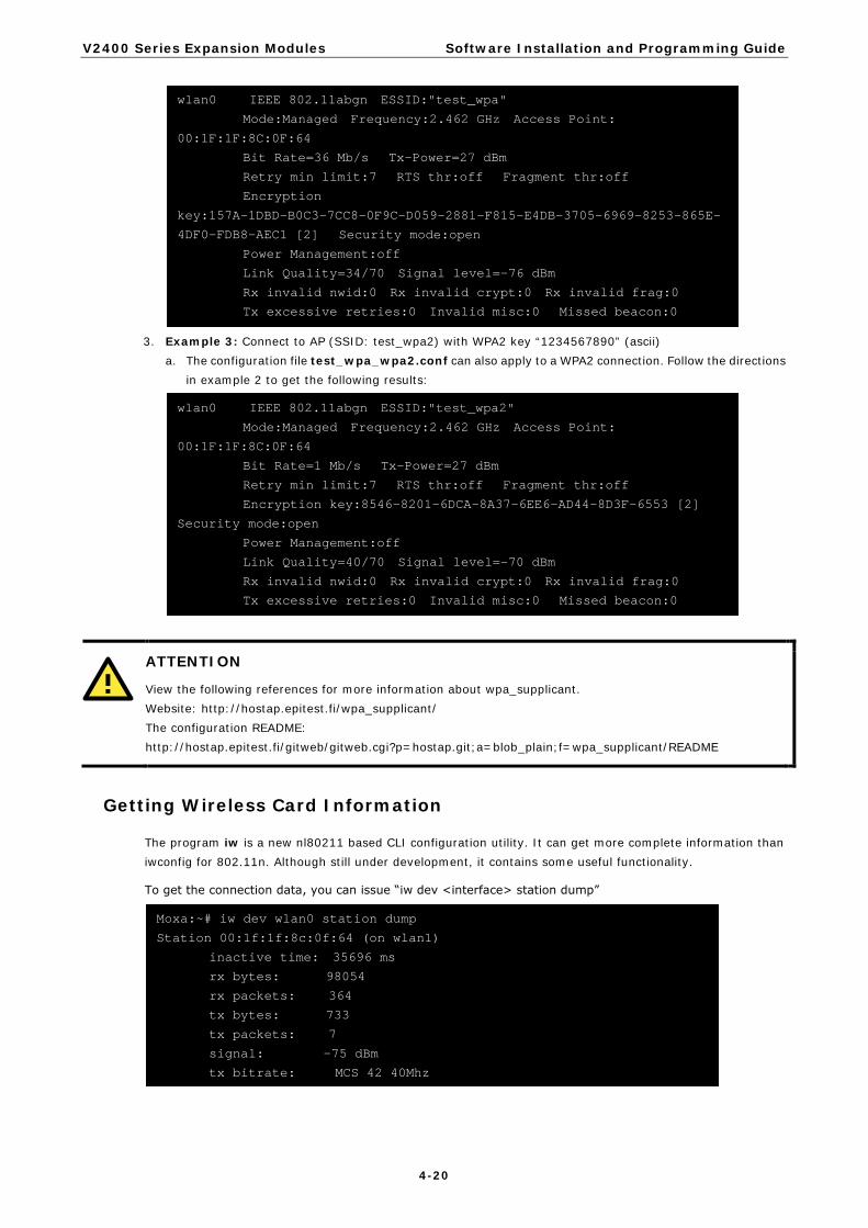
3. Example 3: Connect to AP (SSID: test_wpa2) with WPA2 key “1234567890” (ascii)
a. The configuration file test_wpa_wpa2.conf can also apply to a WPA2 connection. Follow the directions in example 2 to get the following results:
ATTENTION
View the following references for more information about wpa_supplicant. Website: http://hostap.epitest.fi/wpa_supplicant/ The configuration README: http://hostap.epitest.fi/gitweb/gitweb.cgi?p=hostap.git;a=blob_plain;f=wpa_supplicant/README
Getting Wireless Card Information
The program iw is a new nl80211 based CLI configuration utility. It can get more complete information than iwconfig for 802.11n. Although still under development, it contains some useful functionality.
To get the connection data, you can issue “iw dev <interface> station dump”
Moxa:~# iw dev wlan0 station dump
Station 00:1f:1f:8c:0f:64 (on wlan1)
inactive time: 35696 ms
rx bytes: 98054
rx packets: 364
tx bytes: 733
tx packets: 7
signal: -75 dBm
tx bitrate: MCS 42 40Mhz
wlan0 IEEE 802.11abgn ESSID:"test_wpa2"
Mode:Managed Frequency:2.462 GHz Access Point:
00:1F:1F:8C:0F:64
Bit Rate=1 Mb/s Tx-Power=27 dBm
Retry min limit:7 RTS thr:off Fragment thr:off
Encryption key:8546-8201-6DCA-8A37-6EE6-AD44-8D3F-6553 [2]
Security mode:open
Power Management:off
Link Quality=40/70 Signal level=-70 dBm
Rx invalid nwid:0 Rx invalid crypt:0 Rx invalid frag:0
Tx excessive retries:0 Invalid misc:0 Missed beacon:0
wlan0 IEEE 802.11abgn ESSID:"test_wpa"
Mode:Managed Frequency:2.462 GHz Access Point:
00:1F:1F:8C:0F:64
Bit Rate=36 Mb/s Tx-Power=27 dBm
Retry min limit:7 RTS thr:off Fragment thr:off
Encryption
key:157A-1DBD-B0C3-7CC8-0F9C-D059-2881-F815-E4DB-3705-6969-8253-865E-
4DF0-FDB8-AEC1 [2] Security mode:open
Power Management:off
Link Quality=34/70 Signal level=-76 dBm
Rx invalid nwid:0 Rx invalid crypt:0 Rx invalid frag:0
Tx excessive retries:0 Invalid misc:0 Missed beacon:0

V2400 Series Expansion Modules Software Installation and Programming Guide
4-21
ATTENTION
View the following reference for more information about iw. http://linuxwireless.org/en/users/Documentation/iw
EPM-3112 Driver Installation CAN is a broadcast serial bus standard for connecting electronic control units (ECUs). Each node is able to send and receive messages, but not simultaneously: a message (consisting primarily of an ID—usually chosen to identify the message-type/sender—and up to eight message bytes) is transmitted serially onto the bus, one bit after another. This signal-pattern codes the message (in NRZ) and is sensed by all nodes.
Moxa EPM-3112 module provides the CAN bus interface for industrial CAN communication. Users can use the library or file control interface (ioctl) to read, write or control the CAN interface as a file for easy CAN programming.
1. Make root file system writable
2. Install the file epm3112.deb
3. Mount root file system read-only
4. Then modprobe moxa_can or reboot your device to finish this installation
EPM-3112 Programming Guide
CANBUS Library
A simple library mxcanbus_lx.c is offered; see the following sub-sections for details:
Moxa functions for CANbus
Function unsigned int mxcan_get_bus_timing (unsigned int fd)
Description Get the bus timing of an opened port.
Input <fd> the opened port
Output None
Return 0 on failure, otherwise the bus speed in KHz
Function int mxcan_get_parameters (unsigned int fd, CANPRM *param)
Description Get the parameter of an opened port.
Input <fd> the opened port
Output <param> pointer to a structure of CANPRM
Return 0 on success. Otherwise return a negative value
Moxa:~# umount /
Moxa:/home# dpkg -i epm3112.deb
Moxa:~# mount -o remount,rw /

V2400 Series Expansion Modules Software Installation and Programming Guide
4-22
Function int mxcan_get_registers (unsigned int fd, unsigned char *buffer, int num)
Description Get the register values of an opened port.
Input <fd> the opened port <num> number of register values. For module with sja1000 chipset, the value must be 32
Output <buffer> point to a buffer for these values
Return 0 on success, otherwise failure
Function int mxcan_get_stat (unsigned int fd, CANBST *stat)
Description Get the statistics of an opened port.
Input <fd> the opened port
Output <stat> point to a contianer of statistics
Return 0 on success, otherwise failure
Function int mxcan_inqueue (unsigned int fd)
Description Get the number of received bytes that are queued in the driver of an opened port.
Input <fd> the opened port
Output None
Return < 0 on failure, the number of bytes
Function unsigned int mxcan_open (int port)
Description Open a can port by the port number
Input <port> port number starting from 1. In Linux, open port 1 will open /dev/can0
Output None
Return 0 on failure, otherwise return fd
Function int mxcan_outqueue (unsigned int fd)
Description Get the number of bytes waiting for being transmitted to a can port.
Input <fd> the opened port
Output None
Return < 0 on failure, the number of bytes
Function int mxcan_purge_buffer (unsigned int fd, unsigned int purge)
Description Purge the buffers of an opened port.
Input <fd> the opened port <purge> 1: receive data buffer, 2: transmit data buffer, otherwise: both
Output None
Return 0 on success, otherwise failure
Function int mxcan_set_bus_timing (unsigned int fd, unsigned int speed)
Description Set the bus timing of an opened port.
Input <fd> the opened port <speed> bus timing in KHz. The available values are 5/10/20/40/50/80/100/125/200/250/400/500/666/800/1000
Output None
Return 0 on success, otherwise returns a negative value
Function int mxcan_set_nonblocking (unsigned int fd)
Description Set the opened fd to be non-blocking.
Input <fd> the opened port
Output None
Return 0 on success, otherwise returns a negative value

V2400 Series Expansion Modules Software Installation and Programming Guide
4-23
Function int mxcan_set_parameters (unsigned int fd, CANPRM *param)
Description Set the parameter of an opened port.
Input <fd> the opened port <param> pointer to a structure of CANPRM
Output None
Return 0 on success, otherwise return a negative value
Moxa definitions for CANbus
#define mxcan_close(fd) close((int)fd) #define mxcan_read(fd, buffer, size, hndl) read((int)fd, buffer, size) #define mxcan_write(fd, buffer, size, hndl) write((int)fd, buffer, size)
Example Code
You can download the library / example code from MOXA website. http://www.moxa.com/support/support_home.aspx
ATTENTION
View the following reference for more information http://en.wikipedia.org/wiki/Controller_area_network
EPM-3552 Driver Installation The Moxa EPM-3552 module provides the capability of using the display on Moxa’s V2422 and V2426 computers.
1. Make the root file system writable.
2. Install the package epm3552.deb.
3. Install gconf-editor.
4. Install grandr.
5. Start the GNOME desktop environment.
6. Disable the xrandr plug-in of gnome-settings-daemon due to its poor xrandr support. In gnome, launch
Applications System Tools Configuration Editor, and then cancel the xrandr active options at the path /apps/gnome_settings_daemon/plugins/xrandr/.
Moxa:~#/etc/init.d/gdm start
Moxa:~# apt-get install grandr
Moxa:~# apt-get install gconf-editor
Moxa:/home# dpkg -i epm3552.deb
Moxa:~# mount -o remount,rw /

V2400 Series Expansion Modules Software Installation and Programming Guide
4-24
7. Mount the root file system as read-only.
EPM-3552 Chipset Configuration As the V2422 and V2426 computers have already offered the VGA and DVI display outputs, this section illustrates how to configure EPM-3552 to display an independent desktop, so that users can use both displays simultaneously.
1. Connect a monitor to the EPM-3552 module before booting the computer. 2. Back up the original configuration file located at /etc/X11/xorg.conf. 3. Rename the new configuration file from xorg.conf-epm3552-dual to xorg.conf.
Note: For built-in Intel chipset, it is only necessary to setup the Virtual size at the Screen section. Please remove the “Right-of” option in monitor section if existed.
The value “3840 1080” is the maximum resolution of the desktop shared by the built-in VGA/DVI port, which is 1920 x1080 x 2.
4. Set up the initial mode of the built-in VGA/DVI ports. The default value is the maximum resolution of the monitor; you can adjust it in /etc/X11/Xsession.d/45xrandr. a. Display an extended desktop.
#Resolution res=1920x1080 #Extended mode xrandr --output TMDS-1 --mode $res --right-of VGA --output VGA --mode $res #Clone mode
Section "Screen" Identifier "Screen_Intel" Device "Device_Intel" Monitor "VGA" SubSection "Display" Depth 24 Virtual 3840 1080 EndSubSection
Moxa:~# umount /

V2400 Series Expansion Modules Software Installation and Programming Guide
4-25
b. Display a clone desktop
The syntax is as follow: - output: TMDS-1 (DVI) / VGA (VGA) - right-of: the position in extended desktop - same-as: for clone mode setting - mode: resolution
5. Next start the X windows: startx or /etc/init.d/gdm start
NOTE When you plug in 2 EPM3552 modules, uncomment the setting for Device_DL2 / Monitor_DL2/ Screen_DL2 sections and the Screen 2 option in the Server Layout Section.
When finished, connect a monitor to the second EPM-3552 module and reboot your system to activate the settings.
NOTE For Linux systems, the EPM-3552 display module cannot work with the V2422/2426 computers’ built-in VGA/DVI-I display when in Extended Mode or Mirror Mode. Due to limitations of the Linux RandR design, the EPM-3552 display module can only work alone as an independent display.
#Setting for the second EPM3552 module Section "Device" Identifier "Device_DL2" driver "displaylink" Option "fbdev" "/dev/fb1" EndSection Section "Monitor" Identifier "Monitor_DL2" EndSection Section "Screen" Identifier "Screen_DL2" Device "Device_DL2" Monitor "Monitor_DL2" SubSection "Display" Depth 24 EndSubSection EndSection Section "ServerLayout" Identifier "945G-Layout" Screen 0 "Screen_Intel" 0 0 Screen 1 "Screen_DL1" LeftOf "Screen_Intel" " " f f " "
#Resolution res=1920x1080 #Extended mode #xrandr --output TMDS-1 --mode $res --right-of VGA --output VGA --mode $res #Clone mode xrandr --output TMDS-1 --mode $res --same as VGA --output VGA --mode $res xrandr --output TMDS-1 --mode $res --same-as VGA --output VGA --mode $res
V2400 Series Expansion Modules Software Installation and Programming Guide
4-26
Configuration for Displaying only on the EPM-3552
Back up your /etc/X11/xorg.conf file and then rename xorg.conf-epm3552-single to xorg.conf. Next, start Xwindow to launch the display only on the EPM-3552 module.
Dynamically Changing the Display Resolution
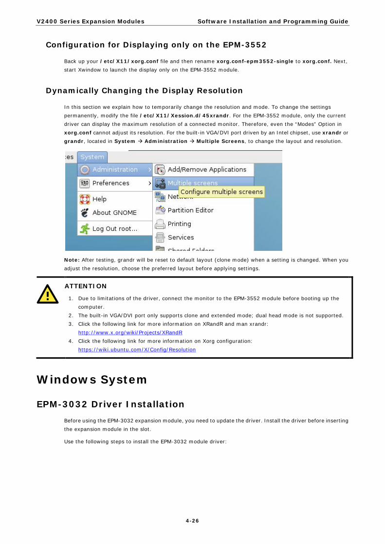
In this section we explain how to temporarily change the resolution and mode. To change the settings permanently, modify the file /etc/X11/Xession.d/45xrandr. For the EPM-3552 module, only the current driver can display the maximum resolution of a connected monitor. Therefore, even the “Modes” Option in xorg.conf cannot adjust its resolution. For the built-in VGA/DVI port driven by an Intel chipset, use xrandr or grandr, located in System Administration Multiple Screens, to change the layout and resolution.
Note: After testing, grandr will be reset to default layout (clone mode) when a setting is changed. When you adjust the resolution, choose the preferred layout before applying settings.
ATTENTION
1. Due to limitations of the driver, connect the monitor to the EPM-3552 module before booting up the computer.
2. The built-in VGA/DVI port only supports clone and extended mode; dual head mode is not supported. 3. Click the following link for more information on XRandR and man xrandr:
http://www.x.org/wiki/Projects/XRandR 4. Click the following link for more information on Xorg configuration:
https://wiki.ubuntu.com/X/Config/Resolution
Windows System
EPM-3032 Driver Installation Before using the EPM-3032 expansion module, you need to update the driver. Install the driver before inserting the expansion module in the slot.
Use the following steps to install the EPM-3032 module driver:

V2400 Series Expansion Modules Software Installation and Programming Guide
4-27
1. Execute EPM3032Setup.exe to install the driver and then click Next.
2. Click Next to install using default settings.
3. Click Next to start the installation.

V2400 Series Expansion Modules Software Installation and Programming Guide
4-28
4. Click Close to complete the installation.
5. At this point, shut down the computer and insert the EPM-3032 expansion module into the embedded
computer, and then reboot the computer. 6. The system will locate the new hardware; select No, not this time and then click Next.
7. Select Install the software automatically and then click Next.

V2400 Series Expansion Modules Software Installation and Programming Guide
4-29
8. The driver will be installed automatically. The module should be listed in the Device Manager window. At this point you can start using the module.
Configuring Serial Port Mode Take the following steps to configure the operation mode of each COM port:
1. Go to the Control Panel Ports (COM & LPT) and select the COM port; e.g., MOXA Port 0 (COM1). 2. Right-click the COM port and then click Properties. 3. Click the Port Settings tab and then select the interface you would like to use.

V2400 Series Expansion Modules Software Installation and Programming Guide
4-30
4. Click OK to apply the settings.
In some situations, you may want to change the port name to match the name used by your program. Take the following steps to change port names:
1. Go to Control Panel Multi-port serial adapters and select the adapter. 2. Right-click the adapter and select Properties.
V2400 Series Expansion Modules Software Installation and Programming Guide
4-31
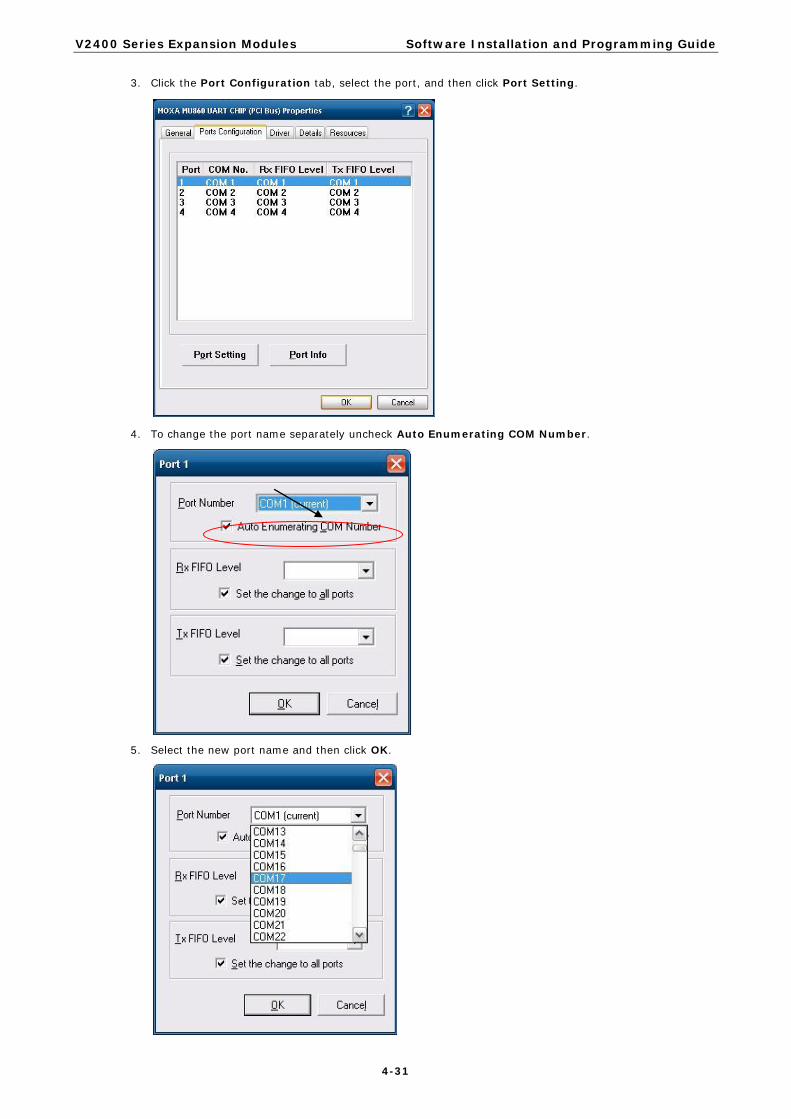
3. Click the Port Configuration tab, select the port, and then click Port Setting.
4. To change the port name separately uncheck Auto Enumerating COM Number.
5. Select the new port name and then click OK.

V2400 Series Expansion Modules Software Installation and Programming Guide
4-32
6. Make sure the port names are correct, and then click OK to activate the settings.
7. Refer to Ports (COM & LPT) to verify that the port names have been changed.
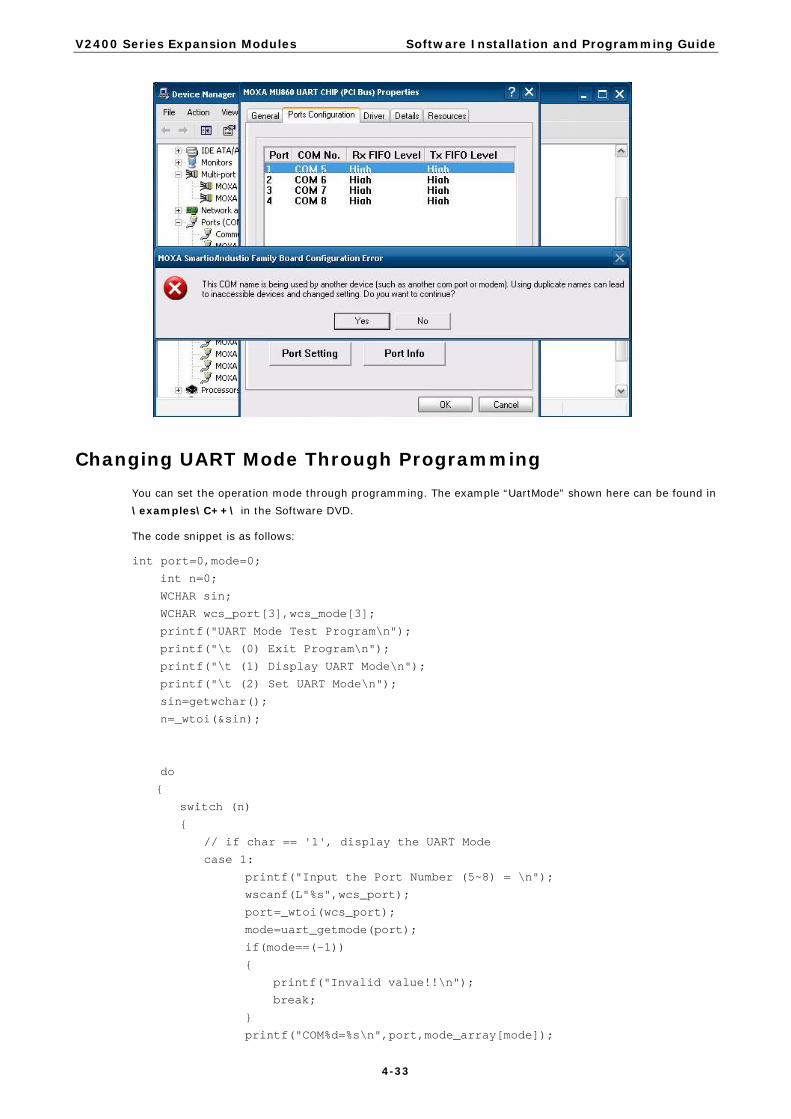
NOTE Make sure each port name is unique; using duplicate names will result in some devices being inaccessible.
V2400 Series Expansion Modules Software Installation and Programming Guide
4-33
Changing UART Mode Through Programming You can set the operation mode through programming. The example “UartMode” shown here can be found in \examples\C++\ in the Software DVD.
The code snippet is as follows:
int port=0,mode=0;
int n=0;
WCHAR sin;
WCHAR wcs_port[3],wcs_mode[3];
printf("UART Mode Test Program\n");
printf("\t (0) Exit Program\n");
printf("\t (1) Display UART Mode\n");
printf("\t (2) Set UART Mode\n");
sin=getwchar();
n=_wtoi(&sin);
do
{
switch (n)
{
// if char == '1', display the UART Mode
case 1:
printf("Input the Port Number (5~8) = \n");
wscanf(L"%s",wcs_port);
port=_wtoi(wcs_port);
mode=uart_getmode(port);
if(mode==(-1))
{
printf("Invalid value!!\n");
break;
}
printf("COM%d=%s\n",port,mode_array[mode]);

V2400 Series Expansion Modules Software Installation and Programming Guide
4-34
break;
// if char == '2', Set the UART Mode
case 2:
//Get Port Number
printf("Input the Port Number (5~8) = \n");
wscanf(L"%s",wcs_port);
port=_wtoi(wcs_port);
//Get Mode Value
printf("Input the Mode value (0 ~ 3) = ");
wscanf(L"%s",wcs_mode);
mode=_wtoi(wcs_mode);
//Set UART Mode
if(uart_setmode(port,mode)==-1)
{
printf("Invalid value!!\n");
printf("Set UART Mode Fail!!\n");
}
else
{
printf("COM%d=%s\n",port,mode_array[mode]);
}
break;
}
getwchar();
sin = getwchar();
n = _wtoi(&sin);
} while (n != 0);
return 0;
EPM-3438 Driver Installation Before installing the EPM-3438, select counter mode or DI mode for the module.
If DIP switch 1 on the EPM-3438 is on, the DI0 will work in digital input port mode. The DI0 just reflects whether the input signal status is HIGH or LOW. If DIP switch 2 on the EPM-3438 is on, the DI0 works as a 16-bit counter. The counter is increased when the input pulse is toggled from low to high. See the following figures for DIP switch settings.

V2400 Series Expansion Modules Software Installation and Programming Guide
4-35
Before using the EPM-3438 expansion module, you need to update the driver. Be sure to install the driver before inserting the expansion module in the slot.
Take the following steps to install the EPM-3438 module driver:
1. Run EPM3438Setup.exe to begin installation and then click Next.
2. Click Next to install using the default settings.
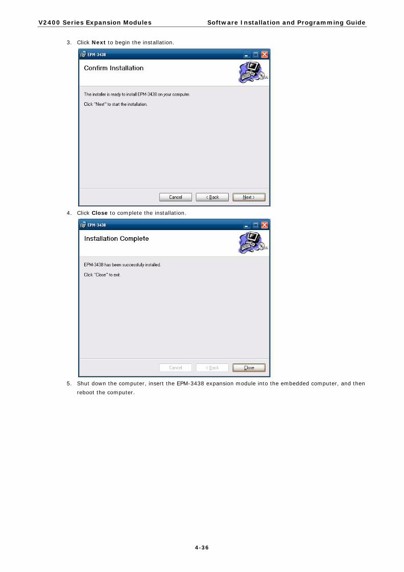
V2400 Series Expansion Modules Software Installation and Programming Guide
4-36
3. Click Next to begin the installation.
4. Click Close to complete the installation.
5. Shut down the computer, insert the EPM-3438 expansion module into the embedded computer, and then
reboot the computer.
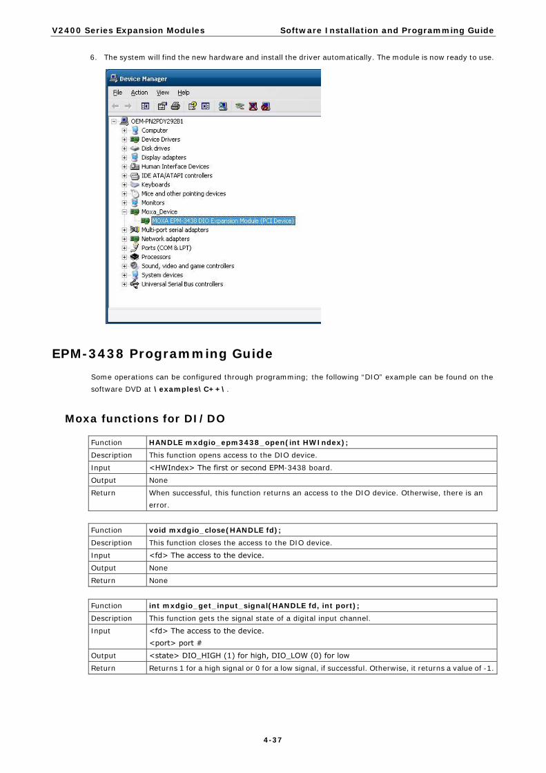
V2400 Series Expansion Modules Software Installation and Programming Guide
4-37
6. The system will find the new hardware and install the driver automatically. The module is now ready to use.
EPM-3438 Programming Guide Some operations can be configured through programming; the following “DIO” example can be found on the software DVD at \examples\C++\.
Moxa functions for DI/DO
Function HANDLE mxdgio_epm3438_open(int HWIndex);
Description This function opens access to the DIO device.
Input <HWIndex> The first or second EPM-3438 board.
Output None
Return When successful, this function returns an access to the DIO device. Otherwise, there is an error.
Function void mxdgio_close(HANDLE fd);
Description This function closes the access to the DIO device.
Input <fd> The access to the device.
Output None
Return None
Function int mxdgio_get_input_signal(HANDLE fd, int port);
Description This function gets the signal state of a digital input channel.
Input <fd> The access to the device. <port> port #
Output <state> DIO_HIGH (1) for high, DIO_LOW (0) for low
Return Returns 1 for a high signal or 0 for a low signal, if successful. Otherwise, it returns a value of -1.

V2400 Series Expansion Modules Software Installation and Programming Guide
4-38
Function int mxdgio_get_output_signal(HANDLE fd, int port);
Description This function gets the signal state of a digital output channel.
Input <fd> The access to the device. <port> Port number
Output None
Return Returns 1 for a high signal or 0 for a low signal, if successful. Otherwise, it returns a value of -1.
Function int mxdgio_set_output_signal_high(HANDLE fd, int port);
Description This function sets a high signal to a digital output channel.
Input <fd> The access to the device. <port> Port number.
Output none.
Return When successful, this function returns 0. When an error occurs, it returns -1.
Function int mxdgio_set_output_signal_low(HANDLE fd, int port);
Description This function sets a low signal to a digital output.
Input <fd> The access to the device. <port> Port number.
Output none.
Return When successful, this function returns 0. When an error occurs, it returns -1.
Moxa I/O control definitions for COUNTER
#define COUNTER_NODE1 "/dev/epm_3438_counter1"
#define COUNTER_NODE2 "/dev/epm_3438_counter2"
Function int mxdgio_epm3438_get_counter(int fd);
Description get the counter value
Input <fd> The access to the counter device. <port> Port number.
Output none.
Return the counter value
Function int mxdgio_epm3438_clear_counter(int fd);
Description Clear the counter value
Input <fd> The access to the counter device. <port> Port number.
Output none.
Return 0:clear success; -n: clear fail

V2400 Series Expansion Modules Software Installation and Programming Guide
4-39
EPM-3337 Driver Installation Take the following steps to install the 3G/GPS driver:
1. Open the directory HC25\HC25_0205ussb_ndis_driver\install\program files\Siemens\HC25 Connection Manager and then double-click DPInst.exe.
2. Click Next.
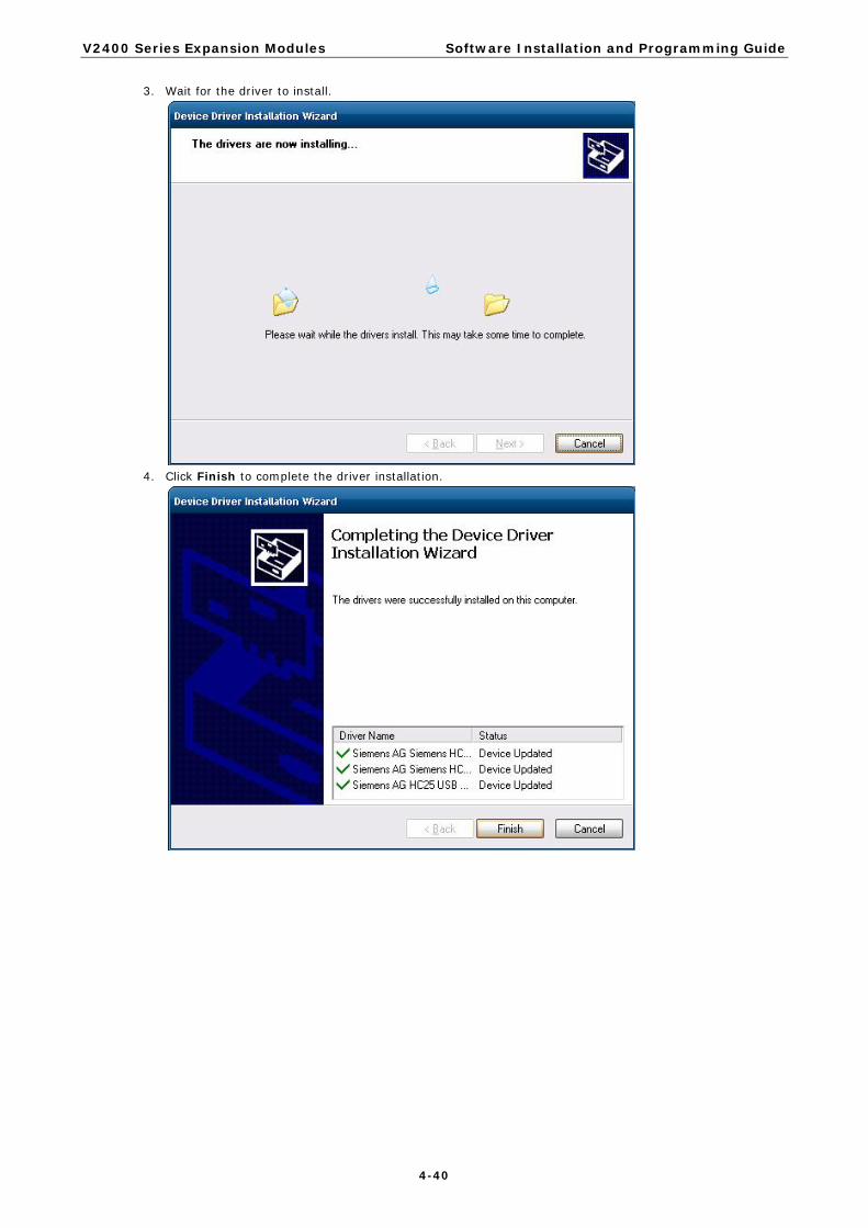
V2400 Series Expansion Modules Software Installation and Programming Guide
4-40
3. Wait for the driver to install.
4. Click Finish to complete the driver installation.

V2400 Series Expansion Modules Software Installation and Programming Guide
4-41
5. Navigate to the \HC25\HC25_usb_ndis_driver\program files\ directory and double-click HC25 Connection Manager.msi.
6. Click Install.

V2400 Series Expansion Modules Software Installation and Programming Guide
4-42
7. During the installation process, if you encounter the following error message, just ignore it and click OK.
8. After the installation is completed, you should see Siemens HC25 HSDPA USB Modem, Siemens HC25
Wireless Ethernet Adapter, and Siemens HC25 USB COM Port in the Device Manager window.

V2400 Series Expansion Modules Software Installation and Programming Guide
4-43
9. Change to the Winmux2K directory and double-click wmux2k.exe.
10. Click Start Scan.

V2400 Series Expansion Modules Software Installation and Programming Guide
4-44
11. Click Install Driver once the scan is complete.
12. Click Install Driver and then Continue Anyway once the scan is complete.
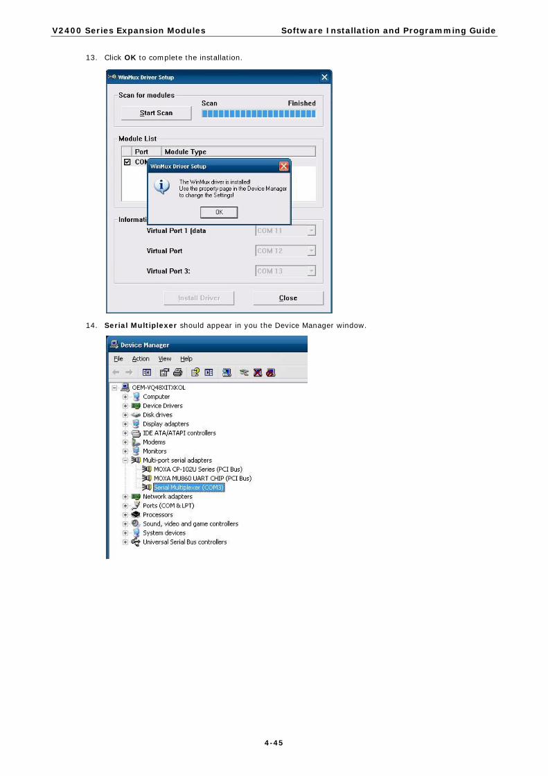
V2400 Series Expansion Modules Software Installation and Programming Guide
4-45
13. Click OK to complete the installation.
14. Serial Multiplexer should appear in you the Device Manager window.

V2400 Series Expansion Modules Software Installation and Programming Guide
4-46
15. Right-click on Serial Multiplexer and select Properties. You will see that 3 virtual serial modem ports have been generated; you can change the port numbers using the drop-down lists.
NOTE Make sure each port name is unique; duplicate names will create glitches.
Wireless Module Driver Installation Take the following steps to install the wireless driver:
1. Click Cancel to stop searching for drivers when you first install the module.
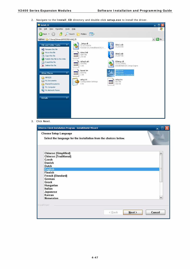
V2400 Series Expansion Modules Software Installation and Programming Guide
4-47
2. Navigate to the Install_CD directory and double-click setup.exe to install the driver.
3. Click Next.

V2400 Series Expansion Modules Software Installation and Programming Guide
4-48
4. Click Next.
5. Select I accept the terms of the license agreement and then click Next.

V2400 Series Expansion Modules Software Installation and Programming Guide
4-49
6. Select Install Client Utilities and Driver and then click Next.
7. Click Next.

V2400 Series Expansion Modules Software Installation and Programming Guide
4-50
8. Click Next.
9. Click Next.

V2400 Series Expansion Modules Software Installation and Programming Guide
4-51
10. Select Atheros Client Utility (ACU) and Supplicant and then click Next.
11. Click Yes.
12. Click OK.
13. Wait for the driver to be installed.

V2400 Series Expansion Modules Software Installation and Programming Guide
4-52
14. Select Yes, I want to restart my computer now and then click Finish.
15. After the installation is complete, you should see Siemens HC25 HSDPA USB Modem, ’Siemens HC25 Wireless Ethernet Adapter, and Siemens HC25 USB COM Port in the Device Manager window.

V2400 Series Expansion Modules Software Installation and Programming Guide
4-53
Configuring the GPRS/HSDPA Connection (without GPS) In this section we illustrate how to establish a connection using the Siemens HC25 Connection Manager utility.
Take the following steps to configure the 3G/GPS and wireless driver:
1. Go to Control Panel System.
2. Click Hardware Device Manager.

V2400 Series Expansion Modules Software Installation and Programming Guide
4-54
3. Right-click Serial Multiplexer Properties Port Settings.
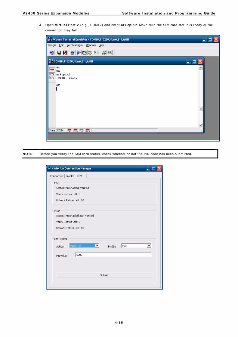
V2400 Series Expansion Modules Software Installation and Programming Guide
4-55
4. Open Virtual Port 2 (e.g., COM12) and enter at+cpin?. Make sure the SIM card status is ready or the connection may fail.
NOTE Before you verify the SIM card status, check whether or not the PIN code has been submitted.
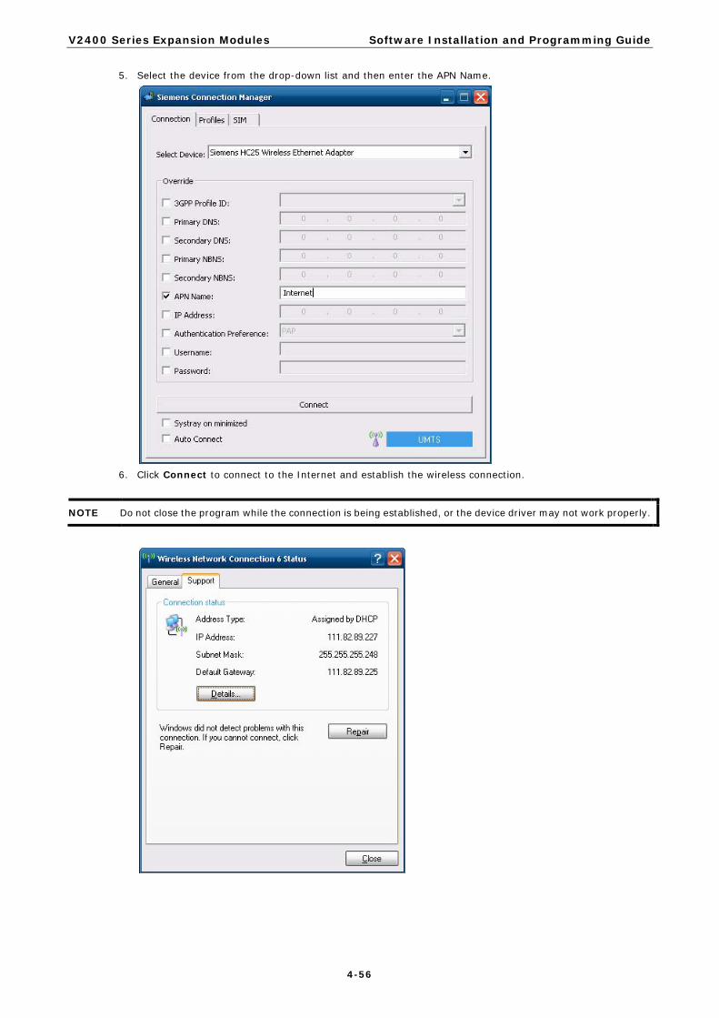
V2400 Series Expansion Modules Software Installation and Programming Guide
4-56
5. Select the device from the drop-down list and then enter the APN Name.
6. Click Connect to connect to the Internet and establish the wireless connection.
NOTE Do not close the program while the connection is being established, or the device driver may not work properly.

V2400 Series Expansion Modules Software Installation and Programming Guide
4-57
7. At this point you can access this wireless network connection.
Enabling GPS Functionality GPS functionality is only enabled when the module is in multiplexer mode. A Winmux2K driver is available for configuring the module in multiplexer mode. In multiplexer mode, the system will generate virtual COM ports to communicate, and the modem port will become one of the virtual COM ports.
Take the following steps below to enable GPS functionality:
1. Start the Device Manager and check the three virtual COM ports.
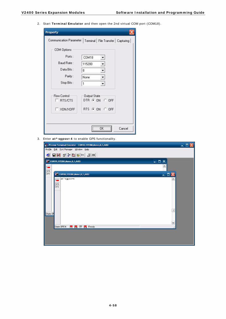
V2400 Series Expansion Modules Software Installation and Programming Guide
4-58
2. Start Terminal Emulator and then open the 2nd virtual COM port (COM18).
3. Enter at^sgpss=4 to enable GPS functionality.

V2400 Series Expansion Modules Software Installation and Programming Guide
4-59
4. Receive the information returned through GPS and verify that the position value is correct.
Configuring a Wireless Connection The EPM-3337 module includes a wireless module. In this section we explain how to connect to an access point with WEP/WPA/WPA2(RSN) encryption.
Take the follow the steps to configure a wireless connection:
1. Double-click on the Atheros client utility shortcut on the desktop. Click on the Profile Management tab, and then click the SCAN button.

V2400 Series Expansion Modules Software Installation and Programming Guide
4-60
2. Select the access point that you want to connect to and then click Activate.
3. Enter the Profile Name and then select the Security tab.

V2400 Series Expansion Modules Software Installation and Programming Guide
4-61
4. Select the security option for your network and then click Configure.
5. Enter the password.

V2400 Series Expansion Modules Software Installation and Programming Guide
4-62
6. The connection will now be established.
Getting Wireless Module Information The Atheros Client Utility can be used to get wireless information and to manage wireless connections.
1. Double-click the Atheros client utility shortcut on the desktop and then select the Current Status tab.
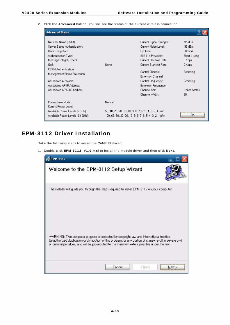
V2400 Series Expansion Modules Software Installation and Programming Guide
4-63
2. Click the Advanced button. You will see the status of the current wireless connection.
EPM-3112 Driver Installation Take the following steps to install the CANBUS driver:
1. Double-click EPM-3112_V1.0.msi to install the module driver and then click Next.

V2400 Series Expansion Modules Software Installation and Programming Guide
4-64
2. Click Next to continue.
3. Click Next to start the driver installation.
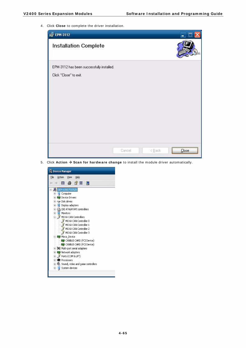
V2400 Series Expansion Modules Software Installation and Programming Guide
4-65
4. Click Close to complete the driver installation.
5. Click Action Scan for hardware change to install the module driver automatically.
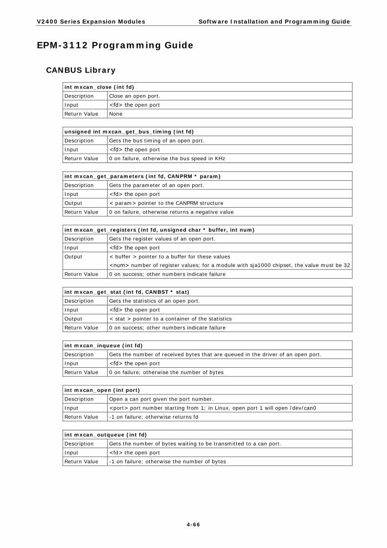
V2400 Series Expansion Modules Software Installation and Programming Guide
4-66
EPM-3112 Programming Guide
CANBUS Library
int mxcan_close (int fd)
Description Close an open port.
Input <fd> the open port
Return Value None
unsigned int mxcan_get_bus_timing (int fd)
Description Gets the bus timing of an open port.
Input <fd> the open port
Return Value 0 on failure, otherwise the bus speed in KHz
int mxcan_get_parameters (int fd, CANPRM * param)
Description Gets the parameter of an open port.
Input <fd> the open port
Output < param> pointer to the CANPRM structure
Return Value 0 on failure, otherwise returns a negative value
int mxcan_get_registers (int fd, unsigned char * buffer, int num)
Description Gets the register values of an open port.
Input <fd> the open port
Output < buffer > pointer to a buffer for these values <num> number of register values; for a module with sja1000 chipset, the value must be 32
Return Value 0 on success; other numbers indicate failure
int mxcan_get_stat (int fd, CANBST * stat)
Description Gets the statistics of an open port.
Input <fd> the open port
Output < stat > pointer to a container of the statistics
Return Value 0 on success; other numbers indicate failure
int mxcan_inqueue (int fd)
Description Gets the number of received bytes that are queued in the driver of an open port.
Input <fd> the open port
Return Value 0 on failure; otherwise the number of bytes
int mxcan_open (int port)
Description Open a can port given the port number.
Input <port> port number starting from 1; in Linux, open port 1 will open /dev/can0
Return Value -1 on failure; otherwise returns fd
int mxcan_outqueue (int fd)
Description Gets the number of bytes waiting to be transmitted to a can port.
Input <fd> the open port
Return Value -1 on failure; otherwise the number of bytes

V2400 Series Expansion Modules Software Installation and Programming Guide
4-67
int mxcan_purge_buffer (int fd, unsigned int purge)
Description Purges the buffers of an open port.
Input <fd> the open port
Output < purge> 1: received data buffer; 2: transmit data buffer; otherwise: both
Return Value 0 on success; otherwise failure
int mxcan_read (int fd, char * buffer, int size)
Description Reads data into a buffer from an open port (the size should be a multiple of the CANMSG size)
Input <fd> the open port
Output <buffer> pointer to the buffer
Return Value 0 on failure (data not available); otherwise the number of bytes read
int mxcan_set_bus_timing (int fd, unsigned int speed)
Description Sets the bus timing of an open port.
Input <fd> the open port
Output <speed> bus timing in Hz
Return Value 0 on success; otherwise returns a negative number
int mxcan_set_nonblocking (int fd)
Description Sets the open fd to be non-blocking.
Input <fd> the open port
Return Value 0 on success; otherwise returns a negative number
int mxcan_set_parameters (int fd, CANPRM * param)
Description Sets the parameters of an open port.
Input <fd> the open port <param> pointer to the CANPRM structure
Output <speed> bus timing in Hz
Return Value 0 on success; otherwise returns a negative number
int mxcan_set_read_timeout (int fd, unsigned int to)
Description Sets data reading timeout of an open port.
Input <fd> the open port <to> timeout in milliseconds
Return Value 0 on success; otherwise failure
int mxcan_set_write_timeout (int fd, unsigned int to)
Description Sets data writing timeout of an open port.
Input <fd> the open port <to> timeout in milliseconds
Return Value 0 on success; otherwise failure
int mxcan_write (int fd, char * buffer, int size)
Description Writes data to the open port
Input <fd> the open port <buffer> pointer to the data <size> size of the data (should be a multiple of the CANMSG size)
Return Value 0 on failure; otherwise the number of bytes written

V2400 Series Expansion Modules Software Installation and Programming Guide
4-68
EPM-3552 Driver Installation Take the following steps to install the EPM-3552 module driver.
ATTENTION
The driver must be installed first. Do not install the EPM-3552 module in the computer before installing the driver.
1. Double click DisplayLink-5.5.29194.exe in the Driver folder on the software CD-ROM, and then click I
Accept to accept the software end user license agreement.
NOTE During the installation, the screen may flash or go black.

V2400 Series Expansion Modules Software Installation and Programming Guide
4-69
2. When finished, install the EPM-3552 module in your embedded computer. The following or similar message will appear on the toolbar.
3. Assign a specific path for the installation driver by clicking Browse, and then select the following path where the driver is located: C:\Windows\system32\DRVStore\displaylin_0C8028254229DB9\
4. Select DisplayLinkUsbPort and then click Open.
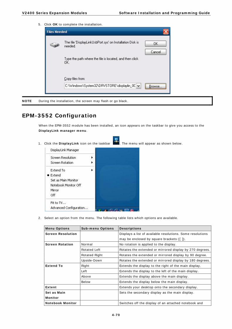
V2400 Series Expansion Modules Software Installation and Programming Guide
4-70
5. Click OK to complete the installation.
NOTE During the installation, the screen may flash or go black.
EPM-3552 Configuration When the EPM-3552 module has been installed, an icon appears on the taskbar to give you access to the DisplayLink manager menu.
1. Click the DisplayLink icon on the taskbar . The menu will appear as shown below.
2. Select an option from the menu. The following table lists which options are available.
Menu Options Sub-menu Options Descriptions
Screen Resolution Displays a list of available resolutions. Some resolutions may be enclosed by square brackets ([ ]).
Screen Rotation Normal No rotation is applied to the display.
Rotated Left Rotates the extended or mirrored display by 270 degrees.
Rotated Right Rotates the extended or mirrored display by 90 degree.
Upside-Down Rotates the extended or mirrored display by 180 degrees.
Extend To Right Extends the display to the right of the main display.
Left Extends the display to the left of the main display.
Above Extends the display above the main display.
Below Extends the display below the main display.
Extent Extends your desktop onto the secondary display.
Set as Main Monitor
Sets the secondary display as the main display.
Notebook Monitor Switches off the display of an attached notebook and

V2400 Series Expansion Modules Software Installation and Programming Guide
4-71
Off makes the DisplayLink display primary.
Mirror Copies what is on the main display and reproduces it on the secondary display.
Off Switches off the secondary display
Fit to TV Opens a GUI to change the size of the Windows desktop so it fits on a V screen.
Setting the Display to Extend Mode with the Windows
Properties 1. Right-click the display and select Properties Settings. 2. Checkmark the Extend my windows desktop onto this computer option. 3. Adjust the screen resolution by dragging the Screen resolution slide bar. 4. Select the Color quality from the drop-down list. 5. In the gray zone, select the monitor icons to match the physical arrangement of the monitors. 6. Click OK to save your settings.
For more detailed settings, including the refresh rate, click Advanced Settings Adapter tab List All Modes. All valid combinations of resolution, color quality, and refresh rate are listed. For CRT monitors, we suggest using a high refresh rate to avoid the discomfort caused by monitor flicker. Flat panel monitors do not flicker, so a lower refresh rate is adequate.

V2400 Series Expansion Modules Software Installation and Programming Guide
4-72
Setting the Display to Extend Mode with the DisplayLink Properties
1. From the taskbar, click the DisplayLink icon. 2. Select Extend.
Setting the Display to Mirror Mode with DisplayLink Properties
To use the Mirror Mode, you must use the DisplayLink Properties. To do this:

V2400 Series Expansion Modules Software Installation and Programming Guide
4-73
1. Right-click the display, and then select Properties Settings. 2. Uncheck the Extend the desktop onto this monitor option. 3. Click Apply.
4. From the taskbar, click the DisplayLink icon. 5. Select Mirror.
NOTE The display resolution of the primary display and the display may be changed to a lower resolution. In mirror mode, both screens must output the same resolution, which may not be the maximum resolution of the display. This mode is NOT recommended if you are using the display as the primary laptop display, since it is unlikely to provide the optimum resolution for the display. See Setting the Display as the Primary Display section for details.
Setting the Display as the Primary Display with Windows Properties
Take the following steps to make the display the primary display.
1. Right-click the display and then select Properties Settings. 2. Checkmark the This is my main monitor option. 3. Click Apply.
NOTE On some PCs and laptops, it is necessary to disable the main display. This is because many primary graphics card drivers tend to make the laptop screen the primary screen if it is enabled. The only workaround for this is to disable the laptop screen to allow another screen to be the primary display.
To disable the main display, clear the Extend the desktop onto this monitor checkbox.

V2400 Series Expansion Modules Software Installation and Programming Guide
4-74
Disabling the Laptop Screen
1. Check the This is my main monitor option. 2. Select the primary display (Display 1). 3. Uncheck the Extend the desktop onto this monitor option. 4. Click Apply.
The display remains as the primary display if the PC enters hibernate or suspend mode or is rebooted. If the display is detached, the main display will once again become the primary display.
Setting the Display as the Primary Display with DisplayLink Properties
1. From the taskbar, click the DisplayLink icon. 2. Select Set as Main Monitor.
EPM-3552 Patch File Installation
Known Technical Issues
The following technical issues will be apparent if you do not install the EPM-3552 patch file.
1. When powering off the V2422/2426 computer, the display connecting to an EPM-3552 module running Extended Mode also shows the shutdown screen. Normally, the display connecting to the EPM-3552 module should remain blank.
2. When the EMP-3552 module has been mounted and the V2422/2426 computer has been powered on, no image shows on the display connected to the DVI-I connector of the V2422/2426 computer. Normally, the image should be visible.
Installing the Patch File
1. Download the patch file from http://www.moxa.com/support. 2. Double click Setup.exe to start the Setup Wizard, and then click Next to continue.
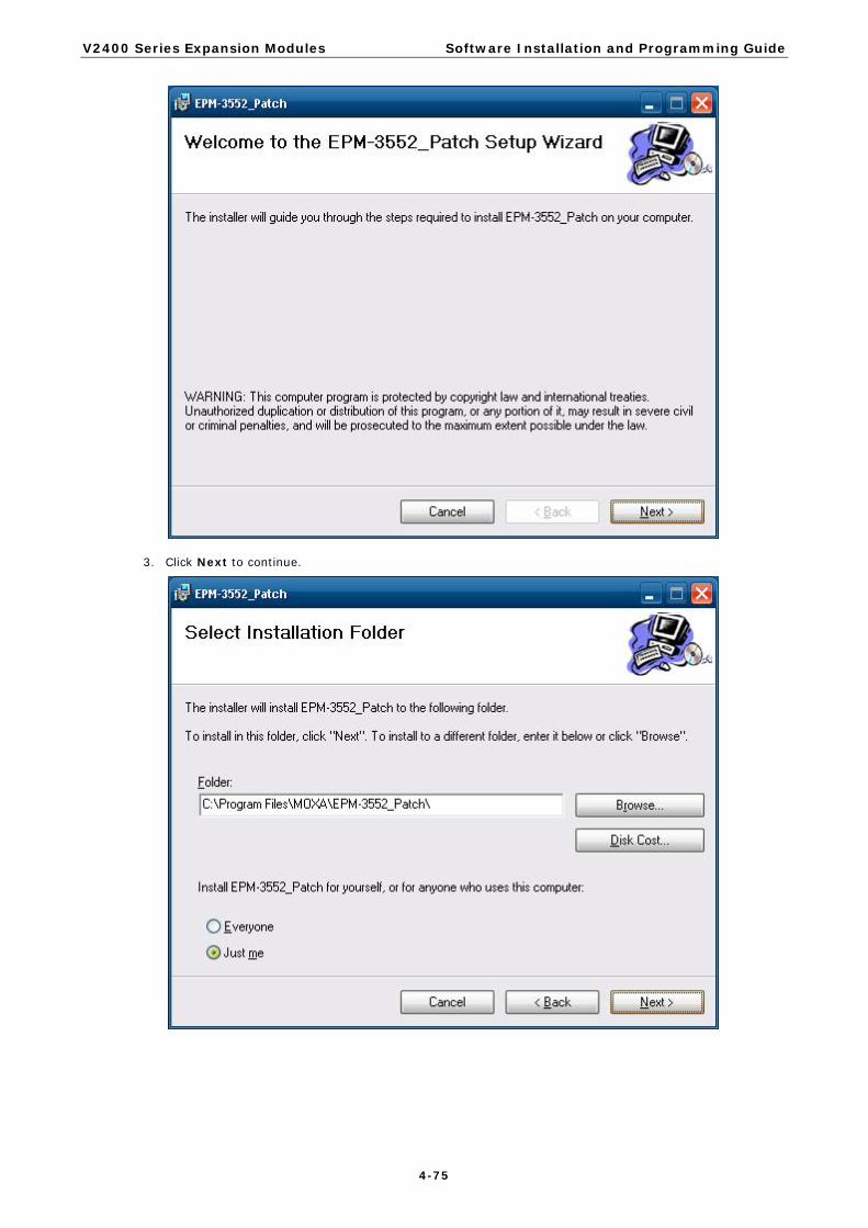
V2400 Series Expansion Modules Software Installation and Programming Guide
4-75
3. Click Next to continue.

V2400 Series Expansion Modules Software Installation and Programming Guide
4-76
4. Click Next to install the patch file.

V2400 Series Expansion Modules Software Installation and Programming Guide
4-77
5. Click Close to complete the installation.
6. Restart the computer by clicking Start Turn Off Computer Restart.

A A. Video Performance Table for the
EPM-3552 Module
The EPM-3552 is a display module that provides a VGA and DVI output function for V2422and V2426 computers. The module is used as the additional display option apart from the VGA/DVI provided by the V2422 and V2426 computers. Moxa provides the display performance tables so that users can optimize the EPM-3552 for specific applications.
This table was produced from an actual performance test with the following parameters: video codec, audio codec, film resolution, frame per second, and bit rates. We strongly suggest that you enable the Hyper-Threading Technology function in the BIOS to ensure better performance of the EPM-3552 display module.
If you would like to use high resolution solutions for your applications, we suggest using the onboard VGA/DVI outputs on the V2422/2426 computers. The EPM-3552 display module is suitable for the applications that require lower resolution for displaying text and small-size figures.

V2400 Series Expansion Modules Video Performance Table for the EPM-3552 Module
A-2
EPM-3552 Display Module Performance on Linux Systems Player mplayer
1.0rc2-4.3.2-DFSG-free
On-board
VGA/DVI
performance on
V24XX
VGA/DVI performance on
EPM-3552
Model V2422/2426-LX EPM-3552-LX
Container Video
Codec
Audio
Codec
Resolution FPS BitRate
(kbps)
System
CPU
loading
Media
Player
/CPU
loading
System
CPU
loading
Media
Player/CPU
loading
Suggested
Configuration
WMV3X WMV WMV3x WMA9 1920 x 1080 29.97 15000 51.4 47.5 46.6 30.7
WMV WMV3x WMA9 1680 x 1050 29.97 12000 50.7 46.8 48.8 33
WMV WMV3x WMA9 1440 x 900 29.97 10000 50.1 46 49.9 33.5
WMV WMV3x WMA9 1280 x 720 29.97 8000 41 38.5 45.8 31.1
WMV WMV3x WMA9 1024 x 600 29.97 7000 29.8 28.4 48.3 33.9
WMV WMV3x WMA9 800 x 480 29.97 6000 20.9 20.1 33.9 23.8
WMV WMV3x WMA9 640 x 400 29.97 4000 14.4 13.7 22.7 16.2
WMV WMV3x WMA9 320 x 200 29.97 2000 6.5 6 8.1 6.5 ★
WMV2X WMV WMV2x WMA8 1920 x 1080 29.97 15000 49.1 45.5 46.7 32.4
WMV WMV2x WMA8 1680 x 1050 29.97 12000 48.8 44.9 48 33.4
WMV WMV2x WMA8 1440 x 900 29.97 10000 47 43.1 48.4 34
WMV WMV2x WMA8 1280 x 720 29.97 8000 42 38 46.4 32.5
WMV WMV2x WMA8 1024 x 600 29.97 7000 28.1 26.8 44.3 31.7 ★
WMV WMV2x WMA8 800 x 480 29.97 6000 18.9 18 29.9 21.2 ★
WMV WMV2x WMA8 640 x 400 29.97 4000 13 12.3 20 14.2 ★
WMV WMV2x WMA8 320 x 200 29.97 2000 6 5.4 7.1 5.6 ★
MPEG-2 MPEG-PS MPEG-2 ac3 1920 x 1080 29.97 15000 43.64 39.2 32 17.1
MPEG-PS MPEG-2 ac3 1680 x 1050 29.97 12000 36.6 32.9 33.7 18.4
MPEG-PS MPEG-2 ac3 1440 x 900 29.97 10000 27.9 25.4 34.4 18.8
MPEG-PS MPEG-2 ac3 1280 x 720 29.97 8000 20.7 18.6 31.5 17.2
MPEG-PS MPEG-2 ac3 1024 x 600 29.97 7000 15.2 13.6 32.2 17.8 ★
MPEG-PS MPEG-2 ac3 800 x 480 29.97 6000 10.9 9.7 22.7 13 ★
MPEG-PS MPEG-2 ac3 640 x 400 29.97 4000 7.6 6.5 16.1 9.1 ★
MPEG-PS MPEG-2 ac3 320 x 200 29.97 2000 3 2.5 4.9 3.1 ★
H.264 /
MPEG-4
MPEG-4 H.264/M
4 AVC
M4 AAC 1920 x 1080 29.97 15000 51.7 47.4 41.7 27.6
MPEG-4 H.264/M
4 AVC
M4 AAC 1680 x 1050 29.97 12000 51.5 47.3 44.6 29.7
MPEG-4 H.264/M
4 AVC
M4 AAC 1440 x 900 29.97 10000 44.7 42.1 45.6 30.2
MPEG-4 H.264/M
4 AVC
M4 AAC 1280 x 720 29.97 8000 33 31.6 42.4 28.9
MPEG-4 H.264/M
4 AVC
M4 AAC 1024 x 600 29.97 7000 24.5 23.4 42.4 29.1 ★
MPEG-4 H.264/M
4 AVC
M4 AAC 800 x 480 29.97 6000 18.2 17.6 30.3 21 ★
MPEG-4 H.264/M
4 AVC
M4 AAC 640 x 400 29.97 4000 12.9 11.9 20.8 14.6 ★
MPEG-4 H.264/M
4 AVC
M4 AAC 320 x 200 29.97 2000 5.9 5.5 7.4 5.8 ★

V2400 Series Expansion Modules Video Performance Table for the EPM-3552 Module
A-3
AVI AVI MS/MPG
4v2
pcm 1920 x 1080 29.97 15000 48.8 42.7 35.2 19.9
AVI MS/MPG
4v2
pcm 1680 x 1050 29.97 12000 38.3 34.2 36 21.1
AVI MS/MPG
4v2
pcm 1440 x 900 29.97 10000 28.9 26 36.7 21.2
AVI MS/MPG
4v2
pcm 1280 x 720 29.97 8000 21.4 19.2 34.2 19.4
AVI MS/MPG
4v2
pcm 1024 x 600 29.97 7000 15.9 14.1 32.7 19.2 ★
AVI MS/MPG
4v2
pcm 800 x 480 29.97 6000 10.6 9.4 22.6 13.2 ★
AVI MS/MPG
4v2
pcm 640 x 400 29.97 4000 7.2 6.1 15.4 8.8 ★
AVI MS/MPG
4v2
pcm 320 x 200 29.97 2000 2.74 2 4.4 2.6 ★
AVI
(DivX)
AVI DivX-5 mp3 1920 x 1080 29.97 15000 49.1 42.6 35.8 20.4
AVI DivX-5 mp3 1680 x 1050 29.97 12000 37.9 34.4 36.8 21.4
AVI DivX-5 mp3 1440 x 900 29.97 10000 28.6 26.1 36.9 21.7
AVI DivX-5 mp3 1280 x 720 29.97 8000 21.5 19.6 34 20
AVI DivX-5 mp3 1024 x 600 29.97 7000 15.9 14.2 33.8 20 ★
AVI DivX-5 mp3 800 x 480 29.97 6000 10.9 9.8 23 13.6 ★
AVI DivX-5 mp3 640 x 400 29.97 4000 7.5 6.6 16 9.3 ★
AVI DivX-5 mp3 320 x 200 29.97 2000 3.2 2.8 5 3.4 ★
EPM-3552 Display Module Performance on Windows Systems Player Media Player Classic - Home Cinema
v1.4.1.2834
On-board VGA/DVI
performance on V24XX
VGA/DVI performance on
EPM-3552
Film Parameters V2422/V2426-XPE EPM-3552
Container Video
Codec
Audio
Codec
Resolution FPS BitRate
(KBS/)
System
CPU
loading
Media Player
/CPU loading
System
CPU
loading
Media
Player/CPU
loading
Suggested
Configuration
WMV WMV3x WMA9 1920 x 1080 29.97 15000 52.4 50.6 95.9 47.8
WMV WMV3x WMA9 1680 x 1050 29.97 12000 52 50.1 96.7 48.5
WMV WMV3x WMA9 1440 x 900 29.97 10000 50.1 48.4 92.7 47.9
WMV WMV3x WMA9 1280 x 720 29.97 8000 37.7 35.7 90.4 46.6
WMV WMV3x WMA9 1024 x 600 29.97 7000 29.2 27.7 74.9 35.8
WMV WMV3x WMA9 800 x 480 29.97 6000 23.1 21.6 67 26.3 ★
WMV WMV3x WMA9 640 x 400 29.97 4000 23.5 21.9 53.6 22 ★
WMV WMV3x WMA9 320 x 200 29.97 2000 10.5 9 23.1 10.7 ★
WMV WMV2x WMA8 1920 x 1080 29.97 15000 48.1 46.9 92.5 47.2
WMV WMV2x WMA8 1680 x 1050 29.97 12000 46.1 44.8 91.8 46.4
WMV WMV2x WMA8 1440 x 900 29.97 10000 38.1 36.4 86.1 44.8
WMV WMV2x WMA8 1280 x 720 29.97 8000 29.4 28 75.7 36.4
WMV WMV2x WMA8 1024 x 600 29.97 7000 21.2 19.7 63.9 25.3 ★
WMV WMV2x WMA8 800 x 480 29.97 6000 19.3 17.9 57 19.2 ★
WMV WMV2x WMA8 640 x 400 29.97 4000 17.6 16.2 47.4 19.6 ★
WMV WMV2x WMA8 320 x 200 29.97 2000 8.1 6.7 19.5 8.3 ★

V2400 Series Expansion Modules Video Performance Table for the EPM-3552 Module
A-4
MPEG-PS MPEG-2 ac3 1920 x 1080 29.97 15000 42.6 40.9 95.4 47.4
MPEG-PS MPEG-2 ac3 1680 x 1050 29.97 12000 36.2 34.7 94.5 46.4
MPEG-PS MPEG-2 ac3 1440 x 900 29.97 10000 28.1 26.7 80.4 34 ★
MPEG-PS MPEG-2 ac3 1280 x 720 29.97 8000 21.7 20.1 68.8 24.9 ★
MPEG-PS MPEG-2 ac3 1024 x 600 29.97 7000 17 15.5 60.5 19.2 ★
MPEG-PS MPEG-2 ac3 800 x 480 29.97 6000 12.8 11.6 54.6 14.1 ★
MPEG-PS MPEG-2 ac3 640 x 400 29.97 4000 9.6 8.3 39.6 10.8 ★
MPEG-PS MPEG-2 ac3 320 x 200 29.97 2000 5.3 3.9 16.7 5.8 ★
MPEG-4 H.264/M4 AVC M4 AAC 1920 x 1080 29.97 15000 54.3 51.8 91.7 44.4
MPEG-4 H.264/M4 AVC M4 AAC 1680 x 1050 29.97 12000 43.9 43.1 93.1 45.2
MPEG-4 H.264/M4 AVC M4 AAC 1440 x 900 29.97 10000 36.6 35.1 85.4 41.4
MPEG-4 H.264/M4 AVC M4 AAC 1280 x 720 29.97 8000 28.5 26.8 77.6 34.2 ★
MPEG-4 H.264/M4 AVC M4 AAC 1024 x 600 29.97 7000 21.8 20.3 67 26.1 ★
MPEG-4 H.264/M4 AVC M4 AAC 800 x 480 29.97 6000 16.5 15 60.5 19.1 ★
MPEG-4 H.264/M4 AVC M4 AAC 640 x 400 29.97 4000 11.9 10.4 43.5 14.2 ★
MPEG-4 H.264/M4 AVC M4 AAC 320 x 200 29.97 2000 6.7 5.1 17.9 6.2 ★
AVI MS/MPG4v2 pcm 1920 x 1080 29.97 15000 51.8 50.1 94.2 48.3
AVI MS/MPG4v2 pcm 1680 x 1050 29.97 12000 51.4 49.9 92.7 48
AVI MS/MPG4v2 pcm 1440 x 900 29.97 10000 51.4 49.6 89.6 47.8
AVI MS/MPG4v2 pcm 1280 x 720 29.97 8000 50.6 49.1 88.2 47.8
AVI MS/MPG4v2 pcm 1024 x 600 29.97 7000 36.4 35 78.4 40.8
AVI MS/MPG4v2 pcm 800 x 480 29.97 6000 24.9 23.4 67.7 27.2 ★
AVI MS/MPG4v2 pcm 640 x 400 29.97 4000 17.1 15.5 48.9 18.2 ★
AVI MS/MPG4v2 pcm 320 x 200 29.97 2000 6.1 4.6 17 5.4 ★
AVI DivX-5 mp3 1920 x 1080 29.97 15000 47.9 46.3 78.5 34.4
AVI DivX-5 mp3 1680 x 1050 29.97 12000 41.8 39.9 81.3 36.6
AVI DivX-5 mp3 1440 x 900 29.97 10000 33.5 31.9 85.7 41.1
AVI DivX-5 mp3 1280 x 720 29.97 8000 27.1 25.4 74.6 32.2 ★
AVI DivX-5 mp3 1024 x 600 29.97 7000 19.7 18.2 64.6 23.3 ★
AVI DivX-5 mp3 800 x 480 29.97 6000 14.9 13.2 56.8 16.6 ★
AVI DivX-5 mp3 640 x 400 29.97 4000 10.9 9.4 39.8 12.5 ★
AVI DivX-5 mp3 320 x 200 29.97 2000 6.4 4.9 17.1 5.6 ★