Embed Size (px)
Citation preview
EPS - PROJECT
1Final report - EPS 2010
TITLE: Design of a state-of-the-art wheelchair
STUDENTS: Thomas Luleich
Vanessa Fix Wojciech Dobrzycki Yevgeny Chernov Hanneke Staal
SUPERVISORS: Raquel Vállez, Manel Membrilla, Dolores López, Xavier Villasevil, Julio Vigara Ernest Perera.
DATE: 10 June 2010
TITLE: Design of a state-of-the-art wheelchair
FAMILY NAME: Fix FIRST NAME: Vanessa
HOME UNIVERSITY: Fachhochschule Kempten
SPECIALITY: Industrial Engineering
FAMILY NAME: Staal FIRST NAME: Hanneke
HOME UNIVERSITY: The Hague University
SPECIALITY: Marketing and Commerce
FAMILY NAME: Dobrzycki FIRST NAME: Wojciech
HOME UNIVERSITY: Technical University of Lodz
SPECIALITY: Biotechnology
FAMILY NAME: Chernov FIRST NAME: Yevgeny
HOME UNIVERSITY: Technical University of Catalonia
SPECIALITY: Mechanical Engineering
FAMILY NAME: Luleich FIRST NAME: Thomas
HOME UNIVERSITY: University of Applied Sciences Kiel
SPECIALITY: Mechanical Engineering
2Final report - EPS 2010
Abstract
State-of-the-art wheelchair. There are some people for whom transportation from place to place is much harder than for the others – disabled people have to put much more effort in moving than anyone else. Also nowadays the level of communication and socialization strongly depends on how fast and effectively we are able to travel. The main aim of our project is to deliver a design of an innovative wheelchair that will facilitate disabled people in moving. Nevertheless the team had to also take in to account that the wheelchair as a product should be competitive on the market and attractive to potential consumers. In order to design such a wheelchair we decided to make a survey to find information about what the expectations of our target group are. After the analysis of the survey results and intensive market research we were able to choose from many interesting options the best one which meets the needs of users and is also attractive from an economical point of view. The result is the design of an innovative wheelchair in the Solid Works program. The new wheelchair has features that will make users not susceptible to weather conditions and will also increase their mobility in the urban terrain. It will bring a new quality onto the wheelchair market and will make disabled people more mobile than ever.
Key words:
• Wheelchair (Articles and newspapers)• Wheel types (Electrical / Mechanical), Types ( sport, climbing, daily use)• Special materials for: seats, wheels, pips• Different wheelchair companies• Functionality• Wheelchair (Conference)• Wheelchair ( University Projects)• Price• Different types of users• Accessibilities• Problems and barriers
3Final report - EPS 2010
The preface
This is the final report of the wheelchair project group. This report is made by students of the European Project Semester 2010 and it is about a state-of-the-art wheelchair.
The students are: Thomas Luleich, Vanessa Fix, Wojciech Dobrzycki, Yevgeny Chernov and Hanneke Staal. They want to thank their supervisors, companies and all the different persons who helped them with this report.
We confirm that we have done the report by ourselves.
(Date, Place)
(Vanessa Fix)
(Hanneke Staal
(Wojciech Dobrzycki)
(Yevgeny Chernov)
(Thomas Luleich)
4Final report - EPS 2010
Index
1. Market research ............................................................................................................ 8 1.1 Introduction ............................................................................................................. 8 1.2 Internal analyses ...................................................................................................... 8
1.2.1 Company and contact persons .......................................................................... 8 1.2.2 Mission/Vision .................................................................................................. 8 1.2.3 Marketing and sales .......................................................................................... 8 1.2.4 Product .............................................................................................................. 8 1.2.5 Place .................................................................................................................. 8 1.2.6 Promotion ......................................................................................................... 9 1.2.7 Price .................................................................................................................. 9 1.2.8 Service .............................................................................................................. 9 1.2.9 Strength of the company ................................................................................... 9 1.2.10 Weaknesses of the company ........................................................................... 9
1.3 Desk research .......................................................................................................... 9 1.3.1 Different types of users ............................................................................. 9 1.3.2 Wheelchair types .............................................................................................. 9 1.3.3 Wheelchair features ........................................................................................ 10 1.3.4 Innovation elements ........................................................................................ 11
1.4 External Analyses .................................................................................................. 11 1.4.1 Demographic factors ....................................................................................... 11 1.4.2 Economical factors ......................................................................................... 12 1.4.3 Social cultural factors .................................................................................... 12 1.4.4 Technological factors ..................................................................................... 12 1.4.5 Ecological factors ........................................................................................... 12 1.4.6 Political factors ............................................................................................... 12
1.5 Field research – The survey ................................................................................... 13 1.5.1 Definition survey ............................................................................................ 13 1.5.2 Questions ........................................................................................................ 13 1.5.3 Conclusion survey .......................................................................................... 14
2. SWOT – Analyses and Confrontation Matrix ............................................................. 15 2.1 SWOT Analysis ..................................................................................................... 15
2.2 Confrontation matrix ......................................................................................... 16 2.2.1 Conclusion survey .......................................................................................... 17 2.2.2 FOETSLE ....................................................................................................... 17 2.2.3 Strategy ........................................................................................................... 18
3. Design .......................................................................................................................... 19 3.1: Results objective .................................................................................................. 19 3.2 Explanation of the different parts ......................................................................... 19
3.2.1 Measurements ................................................................................................. 19 3.2.2 Single Parts ..................................................................................................... 19 3.2.3 Electronic devices ........................................................................................... 20 3.2.4 Barrier supply system ..................................................................................... 21 3.2.5. Rain cover ...................................................................................................... 22
5Final report - EPS 2010
3.2.6. Frame cover and wheel cover ........................................................................ 23 3.3 Material ................................................................................................................. 24
3.3.1 Material Selection Progress ............................................................................ 24 3.3.2 Material Selection Frame ................................................................................ 26 3.3.2 Material Selection Covers .............................................................................. 35 3.3.3 Material Selection Barrier supply system ...................................................... 40
3.4 Installation ............................................................................................................. 40 3.4.1 Wheelchair set 1 ............................................................................................ 40 3.4.2 Wheelchair set 2 ............................................................................................. 47 3.4.3 Wheelchair set 3 ............................................................................................. 48 3.4.4 Wheelchair set 4 ............................................................................................. 50
3.5 Calculations ........................................................................................................... 52 3.5.1 Calculation of the centre of gravity ................................................................ 52 3.5.2 Calculations of stress and failure .................................................................... 55
3.6 Cost ....................................................................................................................... 59
4. Conclusion ................................................................................................................... 60
5. Bibliography ................................................................................................................ 61
6. Appendix ..................................................................................................................... 62 Appendix 1 Groups and associations .................................................................... 62 Appendix 2 The survey ................................................................................................ 63 Appendix 3 The results in charts. ............................................................................... 65 Appendix 4 The first drafts .......................................................................................... 69 Appendix 5 Electric devices ........................................................................................ 74 Appendix 6 Single Parts .............................................................................................. 77
6Final report - EPS 2010
Introduction
This report starts with the market research to find information about different wheelchairs and the target group. An important question is: what are the users of wheelchairs missing? The information is founded with a survey. At the end you can find new concept of the state-of-the-art wheelchair. In conclusion, this report includes interesting information and advice. The following steps we are following.
1. Study of existing wheelchairs and related projects 2. Proposals of ideas to our wheelchair3. Conceptual design 4. Design of each part 5. Complete CAD work 6. Manufacturing process 7. Materials suppliers 8. Financial budgets, market impact and viability
Definition of the problemDesign of a new state-of-art wheelchair
ObjectiveDesign a new state-of-the-art wheelchair that is innovative in two months. Research the potential market at two different levels. Keep the cost, new elements, wants and needs of the customer in mind.
Research questionsThe research questions are:
o What kind of wheelchairs are on the market?o Are there any innovative elements on the market for
wheelchairs?o Who are the users?o What can be improved on the wheelchair?o What kind of strategy is necessary for this new
wheelchair?
Methodology- Desk researchDesk research is necessary to find secondary information about the target group and the potential market.
- Field researchResearch is also necessary to discover new information about the wants and the needs of the customers. There are different methods of field research. This report includes a survey
-Solid works This programme is used for the design of the state-of-the-art wheelchair, including all different elements.
1. Market research
1.1 IntroductionThis chapter is about market research. There are different kind of researches. Desk research is about “second research”, this is information that already exists. Field research is new founded information. This chapter starts with the intern analysis, this paragraph describes the company. The potential market and users are researched in the second paragraph. The external analysis gives an overview of the whole market in the third paragraph and finally the survey gives results about the wants and needs of the customer.
1.2 Internal analyses
1.2.1 Company and contact personsCompany: Catedra d’accesibilitat: (Accessibility Chair)
The contact persons are:1 Raquel Vállez, 2 Manel Membrilla, 3 Dolores López, 4 Xavier Villasevil, 5 Julio Vigara6 Ernest Perera.
1.2.2 Mission/VisionThe objective of this project is to design a wheel chair which not only meets legal requirements and standards but is also attractive, comfortable and easy to manoeuvre. The design should appeal to everyone, whether they are physically challenged or not.
1.2.3 Marketing and salesThe marketing mix is a combination of instruments which a company can use for there marketing strategy. The use of the instrument depends on the market, target group, competitors and objects of the company and the product. The correct combination of the four (or more) P’s can improve the effectively and the company results.
1.2.4 ProductThe product of Catedra d’accesibilitat is a wheelchair.
• Attractive • Comfortable• Easy to manoeuvre
1.2.5 PlaceCatedra d’accesibilitat is located in Spain. The university UPC is located in Vilanova I la Geltru. This is the place where the wheelchair will be designed and improved. The customers of the new wheelchair are living in Europe.
1.2.6 PromotionCatedra d’accesibilitat is not using any promotion right now.
1.2.7 PriceThe prices of wheelchairs are different and depend on the kind of wheelchair. For this project the following criteria is important. Cost is a crucial factor and keeping it low is important. Reducing expenses in materials and manufacturing is essential.
1.2.8 ServiceThe service of a wheelchair company is very important. The customers must have trust in the company, feel comfortable and feel free to ask any questions. .
1.2.9 Strength of the company
• Innovative• The team is a cooperative group with a wide variety of knowledge• Interested in the needs of the possible users
1.2.10 Weaknesses of the company
• Low budget• Short time of period• Language barrier
1.3 Desk research
1.3.1 Different types of users There can be many reasons why people have to use a wheelchair. Either for a short period of time, for example after an operation most patients feel weak, or may have broken both legs. Which make them require a wheelchair for a few weeks or months. Or there are patients which are dependent on a wheelchair all their life. For example Paralysis due to spinal injury, amputation of both legs, acute Multiple Sclerosis, disabilities affecting their balance, Cerebral Palsy and chronic arthritic conditions are only a few disabilities which adhere a person to a wheelchair.1
1.3.2 Wheelchair typesThere is a wide range of different kinds of wheelchairs. The main difference between them is that they are either manual or electrical. Also there could be information found about iBOT Wheelchairs2, hydraulic Wheelchairs3, shower Wheelchairs4, sport Wheelchairs5, all terrain Wheelchairs6 and transport Wheelchairs7. The main topics which have the greatest importance to us are listed in the next chapter.
1http://www.nabd.org.uk/adaptions/wheelchair.htm2http://www.ibotnow.com/home.html3http://www.ncbi.nlm.nih.gov/pubmed/68425674http://www.1800wheelchair.com/asp/view-product.asp?product_id=10835http://www.spinlife.com/category.cfm?categoryID=86http://www.thewheelchairsite.com/all-terrain-wheelchairs.aspx7http://transportwheelchair.org/
1.3.2.1. Manual Wheelchair
Manual Wheelchairs are driven by pushing on the hand rims, which are made of circular tubing attached to the outside of the large wheels. One-arm drive enables a user to guide and propel a wheelchair from one side. Usually the outer, or smaller rim, is connected to the opposite wheel by a folding axle. Another alternative is a lever-drive chair that propels the chair forwards by using a lever that is pumped back and forth.
1.3.2.2 Electrical Wheelchair
An electric wheelchair is moved around by an electric motor and navigational controls. Motorized wheelchairs are useful for those who are too weak to or unable to move around themselves in a manual wheelchair. The user typically controls speed and direction by operating a joystick on a controller. Many other input devices can be used if the user lacks coordination or the use of the hands or fingers, such as chin controls.
1.3.2.3 Transport Wheelchair
These wheelchairs are mainly made of light materials and can be folded so the user can transport it easily in his car. It endows the user with independence, making him able moving around over large distances, by folding his wheelchair up, storing it in a car or bus and driving with other means. 8
1.3.3 Wheelchair featuresThere are a lot of different types of wheelchairs with all different kind of features. The main features we found interesting are listed below:9101112
• Price • Light weight• High strength• Ultra-compact frame• Attractive carbon steel frame • Weight Capacity• Narrow• Short • Grow able• Adaptable• Fold able• Optional quick release wheels pop off with push of button• Able to change summer and winter tires
8http://en.wikipedia.org/wiki/Wheelchair9http://www.1800wheelchair.com10http://www.ncbi.nlm.nih.gov/pubmed/684256711http://www.thewheelchairsite.com/shower-wheelchairs.aspx12http://www.thewheelchairsite.com/all-terrain-wheelchairs.aspx
• Control of the wheels• Removable armrests• S-shaped seating• Padded back upholstery• Washable material • Low maintenance • Battery Charge • Folding battery tray• Top Speed
1.3.4 Innovation elementsThe following elements can be added to the wheelchair to provide more indulgence and safety.13
• Adjustable Wheelchair Cup Holder• Scooter Adjustable Mirror • Wheelchair Collapsible Flag• Scooter Arm Tote• Wheelchair Alarm• Push Button Wheelchair Seat Belt• Wheelchair Crutch/Cane Holder• Wheelchair Brake Lever Extension
1.4 External AnalysesThis chapter gives perception in trends and social development in six different factors.
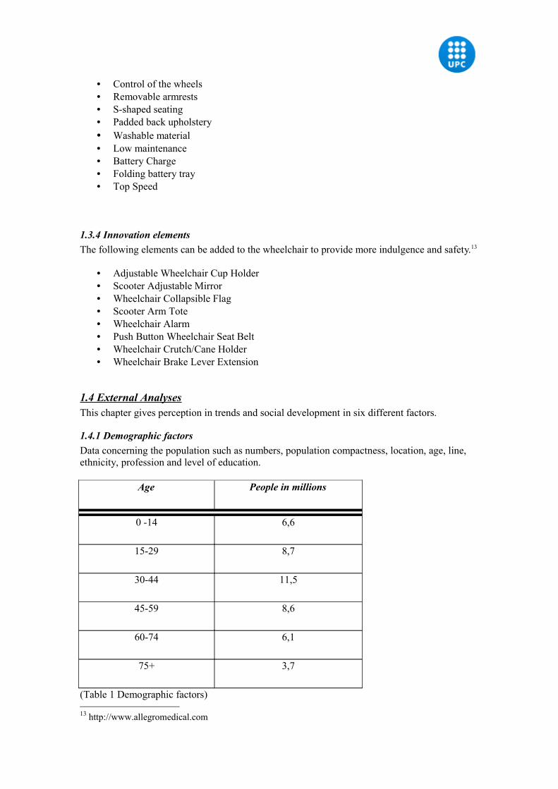
1.4.1 Demographic factorsData concerning the population such as numbers, population compactness, location, age, line, ethnicity, profession and level of education.
Age People in millions
0 -14 6,6
15-29 8,7
30-44 11,5
45-59 8,6
60-74 6,1
75+ 3,7
(Table 1 Demographic factors)
13 http://www.allegromedical.com
Spain has a surface of more than 505.955 km2. Spain has 45,3 million residents. The following table gives an overview of the residents of Spain in millions14.
1.4.2 Economical factorsFactors which influence the purchasing power and expenditure patterns.
More and more people lose their jobs. Spain has a bleak forecast puts unemployment at 22% in 2010 This is a big problem that influence the economy of whole Spain. Moreover, the number of households with all members unemployed rose by 49,900 in the second quarter and 564,400 in one year, bringing the total to 1,118,300, while that of households with all members employed fell by 9 8% to 9,519,40015.
1.4.3 Social cultural factors Circumstances which influence the values and standards, perceptions, preferences and the behaviour of the society.
Customized items all fit in the trend of retailers to add value to their customers and offer them a higher price to charge. It also helps customization to a close relationship between consumer and brand creation. Customization begins with a personal ringtone on your phone, follow one of faux iPod case. Therefore, why not customize a wheelchair?16
1.4.4 Technological factorsNew technologically developments which ensure new product market possibilities.
As the market research shows; the technology in wheelchairs does not stop. New elements and different functions are still entering the market.
1.4.5 Ecological factorsEcological, natural developments which can influence on your company.
As a member of the European union is Spain required to follow the EG-guidelines in product safety, health, protection of the milieu and the customer. The different countries must accept their product provided that they followed these guidelines. Product who are provide with a CE-mark, may be sold at the Spanish market17.
1.4.6 Political factorsLaws, governments and public groups which limit organisations and individuals and/or influence in their actions.
Last may 2010 all 19 precedents of the EU are sitting together for a new European Disability Strategy. This is a good start for disable people to integrated into the economy and enjoy equal rights.
14 www.evd.nl15 http://www.nakedcapitalism.com/2009/07/spain-bleak-forecast-puts-unemployment.html16 http://www.marketingonline.nl/nieuws/bericht/just-do-it-yourself17 www.evd.nl
Quote, Spanish Presidency of the EU:
"I call on all EU Member States to ratify rapidly the UN Convention on the Rights of Persons with Disabilities as soon as possible,” said Commission Vice-President Viviane Reding, EU Commissioner for Justice, Fundamental Rights and Citizenship. “Disability is not only a matter of social welfare. The Convention lays down - as a matter of law - that people with disabilities must be able to fully enjoy all human rights and fundamental freedoms on a non-discriminatory basis. There are also huge business opportunities for companies when it comes to services and equipment destined at people with disabilities. It is the right time for Europe to show commitment and develop a solid framework to deal with people with disabilities18."
1.5 Field research – The survey
1.5.1 Definition surveyA survey is a way of research, done with a questionnaire, which is presented to several persons. These persons can be the complete target group, or have been obtained from a representative sample. The research is about fact and opinions.
Each team member has interviewed ten disable people on the street, on the telephone and on the internet. In total this are fifty interview letters.
1.5.2 QuestionsThe objective of the survey is to understand the needs of the customers. For directory we use the 6W’s from Ferrell by asking the questions. Moreover, who, what, were, when, why and why not.
1. Who: are the customers?2. What: do the customers need?3. Were: do the customers live?4. When: do they face barriers?5. Why: they like their wheelchair?6. Why not, they like their wheelchair?
*You can find the whole survey in appendix2
18 http://www.europa-nu.nl/id/vifag4z8bmzj/nieuws/de_eu_streeft_naar_snelle_ratificatie?ctx=vhsjhdfktnpb
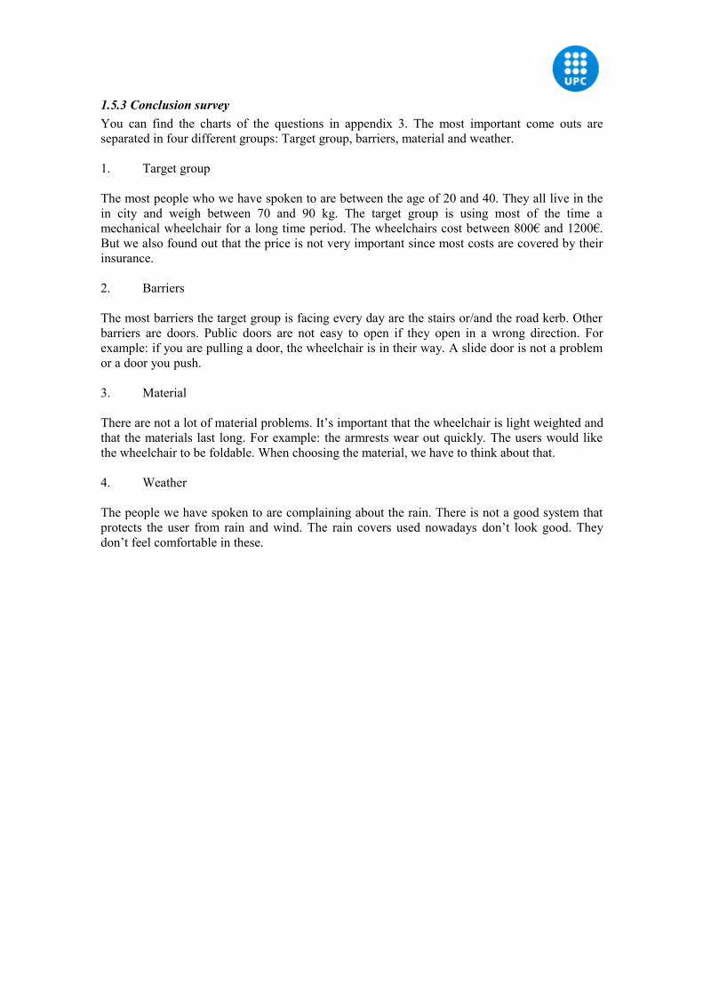
1.5.3 Conclusion surveyYou can find the charts of the questions in appendix 3. The most important come outs are separated in four different groups: Target group, barriers, material and weather.
1. Target group
The most people who we have spoken to are between the age of 20 and 40. They all live in the in city and weigh between 70 and 90 kg. The target group is using most of the time a mechanical wheelchair for a long time period. The wheelchairs cost between 800€ and 1200€. But we also found out that the price is not very important since most costs are covered by their insurance.
2. Barriers
The most barriers the target group is facing every day are the stairs or/and the road kerb. Other barriers are doors. Public doors are not easy to open if they open in a wrong direction. For example: if you are pulling a door, the wheelchair is in their way. A slide door is not a problem or a door you push.
3. Material
There are not a lot of material problems. It’s important that the wheelchair is light weighted and that the materials last long. For example: the armrests wear out quickly. The users would like the wheelchair to be foldable. When choosing the material, we have to think about that.
4. Weather
The people we have spoken to are complaining about the rain. There is not a good system that protects the user from rain and wind. The rain covers used nowadays don’t look good. They don’t feel comfortable in these.
2. SWOT – Analyses and Confrontation Matrix
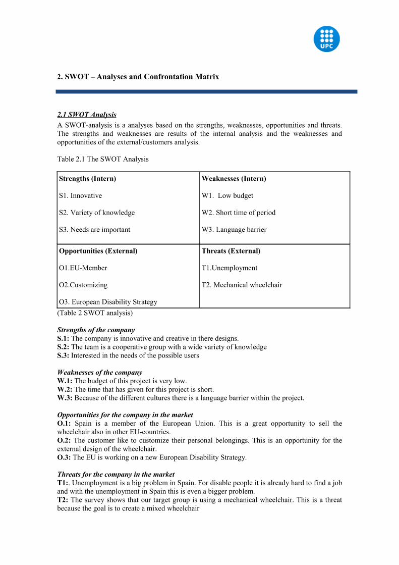
2.1 SWOT AnalysisA SWOT-analysis is a analyses based on the strengths, weaknesses, opportunities and threats. The strengths and weaknesses are results of the internal analysis and the weaknesses and opportunities of the external/customers analysis.
Table 2.1 The SWOT Analysis
Strengths (Intern)
S1. Innovative
S2. Variety of knowledge
S3. Needs are important
Weaknesses (Intern)
W1. Low budget
W2. Short time of period
W3. Language barrier
Opportunities (External)
O1.EU-Member
O2.Customizing
O3. European Disability Strategy
Threats (External)
T1.Unemployment
T2. Mechanical wheelchair
(Table 2 SWOT analysis)
Strengths of the companyS.1: The company is innovative and creative in there designs. S.2: The team is a cooperative group with a wide variety of knowledgeS.3: Interested in the needs of the possible users
Weaknesses of the companyW.1: The budget of this project is very low. W.2: The time that has given for this project is short. W.3: Because of the different cultures there is a language barrier within the project.
Opportunities for the company in the marketO.1: Spain is a member of the European Union. This is a great opportunity to sell the wheelchair also in other EU-countries. O.2: The customer like to customize their personal belongings. This is an opportunity for the external design of the wheelchair. O.3: The EU is working on a new European Disability Strategy.
Threats for the company in the marketT1:. Unemployment is a big problem in Spain. For disable people it is already hard to find a job and with the unemployment in Spain this is even a bigger problem. T2: The survey shows that our target group is using a mechanical wheelchair. This is a threat because the goal is to create a mixed wheelchair
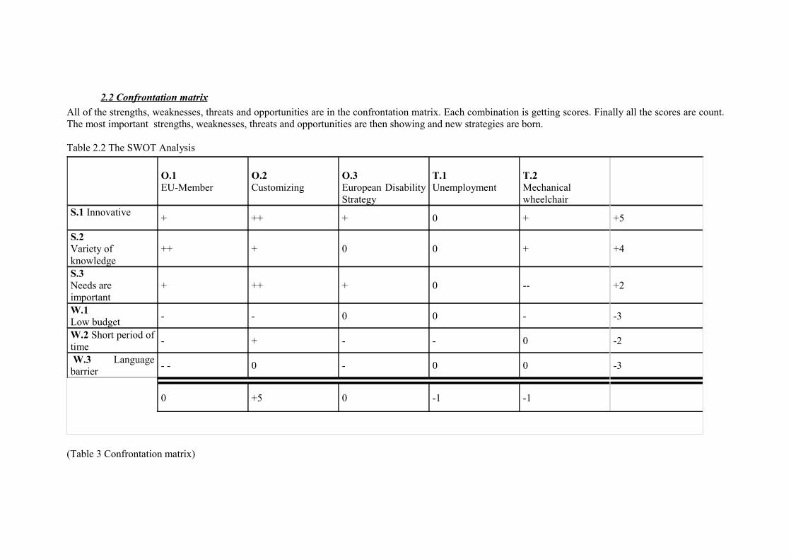
2.2 Confrontation matrixAll of the strengths, weaknesses, threats and opportunities are in the confrontation matrix. Each combination is getting scores. Finally all the scores are count. The most important strengths, weaknesses, threats and opportunities are then showing and new strategies are born.
Table 2.2 The SWOT Analysis
(Table 3 Confrontation matrix)
O.1EU-Member
O.2Customizing
O.3European Disability Strategy
T.1Unemployment
T.2Mechanical wheelchair
S.1 Innovative + ++ + 0 + +5
S.2 Variety of knowledge
++ + 0 0 + +4
S.3Needs are important
+ ++ + 0 -- +2
W.1Low budget - - 0 0 - -3
W.2 Short period of time - + - - 0 -2
W.3 Language barrier - - 0 - 0 0 -3
0 +5 0 -1 -1
2.2.1 Conclusion surveyThe confrontation matrix from the previous page shows the different combinations with the points of how good they fit together. The matrix gives the following options which are possible for the potential market.
Option 1:The strength ” Innovative ” + the opportunity ”Customize” = Attack
The company is very innovative and with a group of different team members customizing is not a problem. A result of the survey is: the customer like to have a change in the external design of the wheelchair. This is a good opportunity for this option. Design the outside of the wheelchair again. This design must include a option to customize the wheelchair by the customer.
Option 2:The strength “ Needs are important” + EU-member “” = Attack
Spain is a member of the EU and the needs of the customer are important. Catedra d’accesibilitat could not only focus on needs op disable people in Spain but also on the need of the customers in other EU countries. Because of the membership it is very easy export to other EU countries.
2.2.2 FOETSLEThe feasibility of the strategic options are based on seven conditions. 7 These conditions are:• Financial. Is the strategy financial feasible?• Organizational. Apply the strategy in the organization?• Economic. Is the strategy in line with the economic objectives of the company?• Technical. Is the strategy technically possible?• Social. Is the strategy socially acceptable? • Legal. Are there any illegal problems to be expected?• Ecological. Is the strategy ecological (environment)?
Option 1:• Financial: There is enough budget for a new external design.• Organizational: Yes, the company cares about the needs of the customer.• Economic: Yes, this is not a problem. This is the aim of the project.• Technical: Yes, because of the variety of knowledge.• Social: Yes, this is a need of the customer. • Legal: There are no illegal problems to be expected.• Ecological: The new design can be environment prove.
Option 2:• Financial: No, the budget is to small for a international project.• Organizational: Yes, the company cares about the needs of the customer.• Economic: This is not the economic objective.• Technical: May be. We need someone for the export.• Social: Yes, there is no social problem. • Legal: Yes, because of the EU-membership.• Ecological: Depends on the wheelchair and the strategy.
2.2.3 StrategyThe results of FOETSLE shows that the feasibility of the first option is the biggest. This means that the strategy is to create a new wheelchair which is able to customize by the potential customers.
After a brainstorm session with our group we came to the following idea; a wheelchair cover. This cover is easy to remove and change it. The cover can be stuck on with different designs. For example, flowers, fire, a sea, land shape or a photo made by the customers. With this cover the customer is able to customize the wheelchair with their own ideas and preferences. We have chosen for a sticker because this is easy to change. It is also cheaper to just change the sticker than a whole cover. A lot of wheelchairs are the same and this is the way to distinguish for the customers.
3. Design
3 .1: Results objective The objective was the design a new state-of-the-art wheelchair that is innovative in two months. Research the potential market at two different levels. Keep the cost, new elements, wants and needs of the customer in mind.
The conclusion of the market research, is the result of the objective. In the following paragraphs the results are explained in detail. To summarize, the main results are; the measurements, the electronic devices, the barrier supply system , the rain cover, the frame - and wheel cover, the materials, the installation, the calculations and the costs.
3.2 Explanation of the different parts
3.2.1 Measurements
3.2.1.1 Height
The height is 920mm.We chose this height due to our research results which were between 850mm and 1270mm. It enables the user to be in a sitting height. It fits under most tables.19
3.2.1.2 Width
The width is 600mm. This was chosen due to most door sizes, to assure the wheelchair user to be able to go in and out of buildings easily. Keeping it as small as possible even with the covers attached.
3.2.1.3 Length
The length is 990mm, because most wheelchair users asked for a narrow wheelchair, in order to move around inside a house or building more freely, having less problems with obstacles.
3.2.2 Single Parts
3.2.2.1 Frame
This design was chosen, because usually wheelchairs look very alike and the customers wanted something new and attractive. This frame fulfils the users need for an new design even if the frame is not covered.
3.2.2.2 Wheels
The rear wheels have a diameter of 540mm and are 28 mm wide. The front wheels have a diameter of 150 and are 20 mm wide. We came to this result due to our result results and these were the norm measurements.
19http://nullbarriere.de/rollstuhl.htm?layout=nullbarriere
3.2.2.3 Arm rest The arm rests are 200 mm long, and 40mm wide, because this length is very comfortable to rest the arm.
3.2.2.4 Seat
The seat is made out of two parts which we needed to enable the wheelchair to be foldable. Each part is 190 mm wide and 350 cm long, they are joint together with a hinge; therefore the complete seat size is 380 mm wide and 350 mm long.
3.2.2.5 Back rest
The back rest is 420 mm wide and 360 mm long. Since this size is very comfortable to rest the back,
3.2.3 Electronic devicesThe speciality about this element is that it allows the user to go on long distance trips. As it can be exhausting propelling a wheelchair all day, this system can be turned on if necessary to help the user ride for approximately 15 km with the support of the battery and the brush less engine. So this allows the users to enjoy long trips in the nature even more.The necessary devices which are needed are a battery, an engine, a controller, a throttle and wires. The devices can be bought in the internet and directly installed to the wheelchair.
3.2.3.1 Battery
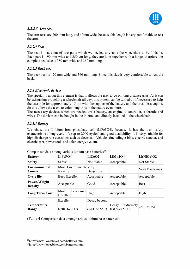
We chose the Lithium iron phosphate cell (LiFePO4), because it has the best safety characteristics, long cycle life (up to 2000 cycles) and good availability. It is very suitable for high discharge rate occasions such as electrical Vehicles (including e-bike, electric scooter, and electric car), power tools and solar energy system.
Comparison data among various lithium base batteries20:Battery LiFePO4 LiCoO2 LiMn2O4 Li(NiCo)O2Safety Safest Not Stable Acceptable Not StableEnvironmental Concern
Most Environment-friendly
Very Dangerous Very Dangerous
Cycle life Best/ Excellent Acceptable Acceptable AcceptablePower/Weight Density Acceptable Good Acceptable Best
Long Term Cost Most Economic/ Excellent High Acceptable High
Temperature Range
Excellent
(-20C to 70C)
Decay beyond
(-20C to 55C)Decay extremely fast over 50 C -20C to 55C
(Table 4 Comparison data among various lithium base batteries21)
20http://www.iloveebikes.com/batteries.html21http://www.iloveebikes.com/batteries.html
The main characteristics of the battery are, that it has a capacity of up to 378 Watt-Hours. This can give a range of up to 15 km without pedal assist under ideal conditions (on the flats, decent pavement, no wind, continuous velocity and steady throttle).22
3.2.3.2 Engine and Controller
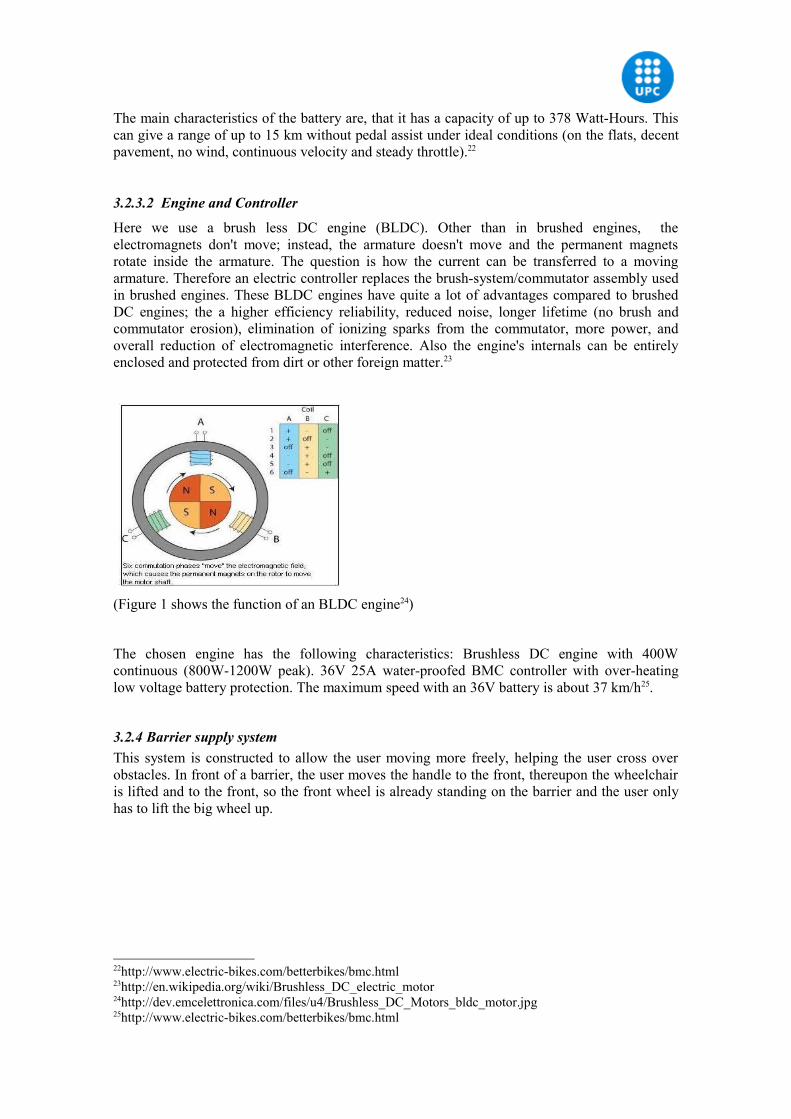
Here we use a brush less DC engine (BLDC). Other than in brushed engines, the electromagnets don't move; instead, the armature doesn't move and the permanent magnets rotate inside the armature. The question is how the current can be transferred to a moving armature. Therefore an electric controller replaces the brush-system/commutator assembly used in brushed engines. These BLDC engines have quite a lot of advantages compared to brushed DC engines; the a higher efficiency reliability, reduced noise, longer lifetime (no brush and commutator erosion), elimination of ionizing sparks from the commutator, more power, and overall reduction of electromagnetic interference. Also the engine's internals can be entirely enclosed and protected from dirt or other foreign matter.23
(Figure 1 shows the function of an BLDC engine24)
The chosen engine has the following characteristics: Brushless DC engine with 400W continuous (800W-1200W peak). 36V 25A water-proofed BMC controller with over-heating low voltage battery protection. The maximum speed with an 36V battery is about 37 km/h25.
3.2.4 Barrier supply systemThis system is constructed to allow the user moving more freely, helping the user cross over obstacles. In front of a barrier, the user moves the handle to the front, thereupon the wheelchair is lifted and to the front, so the front wheel is already standing on the barrier and the user only has to lift the big wheel up.
22http://www.electric-bikes.com/betterbikes/bmc.html23http://en.wikipedia.org/wiki/Brushless_DC_electric_motor24http://dev.emcelettronica.com/files/u4/Brushless_DC_Motors_bldc_motor.jpg25http://www.electric-bikes.com/betterbikes/bmc.html
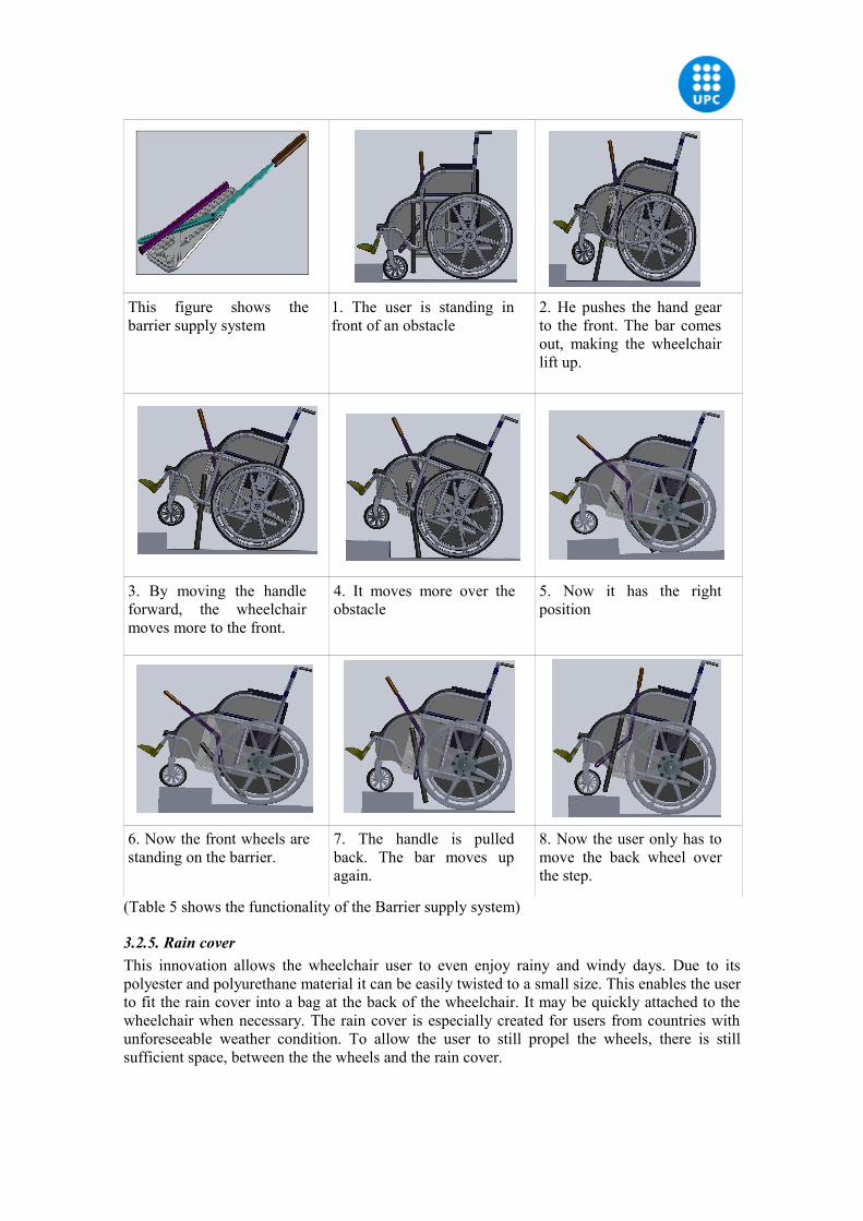
This figure shows the barrier supply system
1. The user is standing in front of an obstacle
2. He pushes the hand gear to the front. The bar comes out, making the wheelchair lift up.
3. By moving the handle forward, the wheelchair moves more to the front.
4. It moves more over the obstacle
5. Now it has the right position
6. Now the front wheels are standing on the barrier.
7. The handle is pulled back. The bar moves up again.
8. Now the user only has to move the back wheel over the step.
(Table 5 shows the functionality of the Barrier supply system)
3.2.5. Rain coverThis innovation allows the wheelchair user to even enjoy rainy and windy days. Due to its polyester and polyurethane material it can be easily twisted to a small size. This enables the user to fit the rain cover into a bag at the back of the wheelchair. It may be quickly attached to the wheelchair when necessary. The rain cover is especially created for users from countries with unforeseeable weather condition. To allow the user to still propel the wheels, there is still sufficient space, between the the wheels and the rain cover.
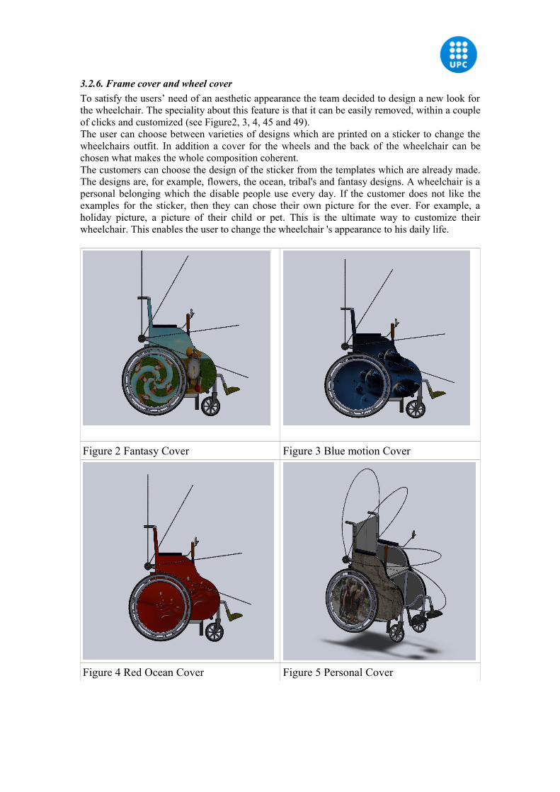
3.2.6. Frame cover and wheel coverTo satisfy the users’ need of an aesthetic appearance the team decided to design a new look for the wheelchair. The speciality about this feature is that it can be easily removed, within a couple of clicks and customized (see Figure2, 3, 4, 45 and 49). The user can choose between varieties of designs which are printed on a sticker to change the wheelchairs outfit. In addition a cover for the wheels and the back of the wheelchair can be chosen what makes the whole composition coherent. The customers can choose the design of the sticker from the templates which are already made. The designs are, for example, flowers, the ocean, tribal's and fantasy designs. A wheelchair is a personal belonging which the disable people use every day. If the customer does not like the examples for the sticker, then they can chose their own picture for the ever. For example, a holiday picture, a picture of their child or pet. This is the ultimate way to customize their wheelchair. This enables the user to change the wheelchair 's appearance to his daily life.
Figure 2 Fantasy Cover Figure 3 Blue motion Cover
Figure 4 Red Ocean Cover Figure 5 Personal Cover
3.3 Material
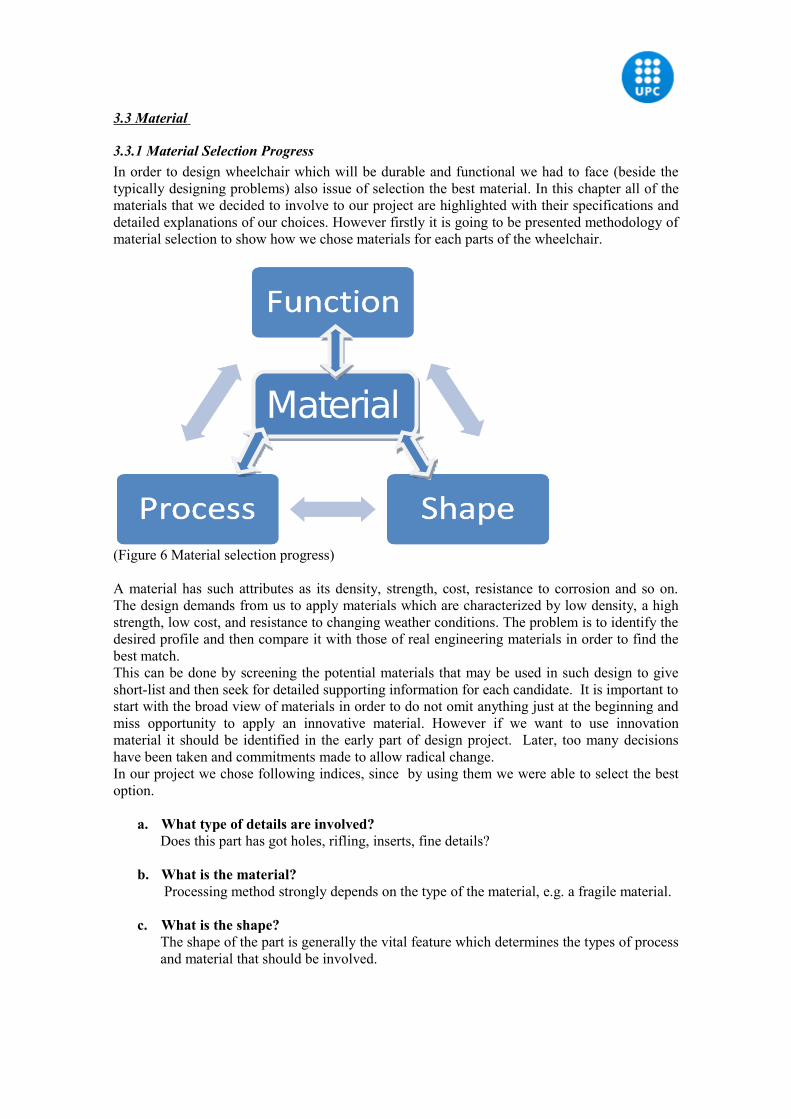
3.3.1 Material Selection ProgressIn order to design wheelchair which will be durable and functional we had to face (beside the typically designing problems) also issue of selection the best material. In this chapter all of the materials that we decided to involve to our project are highlighted with their specifications and detailed explanations of our choices. However firstly it is going to be presented methodology of material selection to show how we chose materials for each parts of the wheelchair.
(Figure 6 Material selection progress) A material has such attributes as its density, strength, cost, resistance to corrosion and so on. The design demands from us to apply materials which are characterized by low density, a high strength, low cost, and resistance to changing weather conditions. The problem is to identify the desired profile and then compare it with those of real engineering materials in order to find the best match.This can be done by screening the potential materials that may be used in such design to give short-list and then seek for detailed supporting information for each candidate. It is important to start with the broad view of materials in order to do not omit anything just at the beginning and miss opportunity to apply an innovative material. However if we want to use innovation material it should be identified in the early part of design project. Later, too many decisions have been taken and commitments made to allow radical change.In our project we chose following indices, since by using them we were able to select the best option.
a. What type of details are involved? Does this part has got holes, rifling, inserts, fine details?
b. What is the material? Processing method strongly depends on the type of the material, e.g. a fragile material.
c. What is the shape? The shape of the part is generally the vital feature which determines the types of process
and material that should be involved.
Material
d. Are there any extra finishing processes?
The part is going to be produced in its final version or it is required to apply extra finishing processes like polishing or painting?
e. What dimensional accuracy and tolerances are required? High accuracy would rule out some methods such as sand casting.
f. What amounts are involved? Is the part a one-off, a small batch, a large batch or continuous production? While some
processes are economic for small quantities others do not become economic until large quantities are involved.
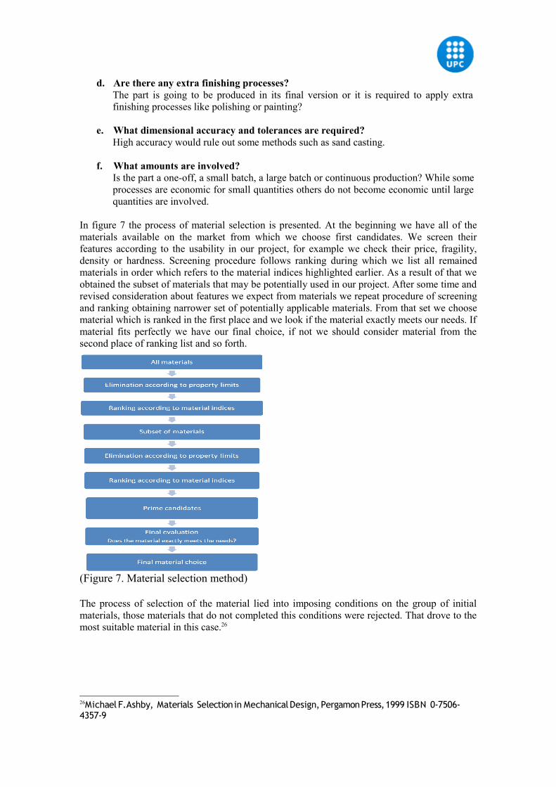
In figure 7 the process of material selection is presented. At the beginning we have all of the materials available on the market from which we choose first candidates. We screen their features according to the usability in our project, for example we check their price, fragility, density or hardness. Screening procedure follows ranking during which we list all remained materials in order which refers to the material indices highlighted earlier. As a result of that we obtained the subset of materials that may be potentially used in our project. After some time and revised consideration about features we expect from materials we repeat procedure of screening and ranking obtaining narrower set of potentially applicable materials. From that set we choose material which is ranked in the first place and we look if the material exactly meets our needs. If material fits perfectly we have our final choice, if not we should consider material from the second place of ranking list and so forth.
(Figure 7. Material selection method)
The process of selection of the material lied into imposing conditions on the group of initial materials, those materials that do not completed this conditions were rejected. That drove to the most suitable material in this case.26
26Michael F.Ashby, Materials Selection in Mechanical Design, Pergamon Press, 1999 ISBN 0-7506-4357-9
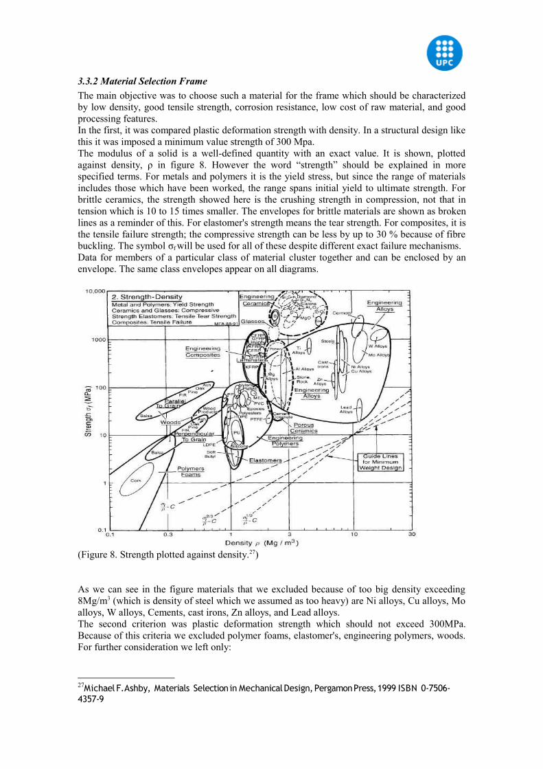
3.3.2 Material Selection FrameThe main objective was to choose such a material for the frame which should be characterized by low density, good tensile strength, corrosion resistance, low cost of raw material, and good processing features.In the first, it was compared plastic deformation strength with density. In a structural design like this it was imposed a minimum value strength of 300 Mpa.The modulus of a solid is a well-defined quantity with an exact value. It is shown, plotted against density, ρ in figure 8. However the word “strength” should be explained in more specified terms. For metals and polymers it is the yield stress, but since the range of materials includes those which have been worked, the range spans initial yield to ultimate strength. For brittle ceramics, the strength showed here is the crushing strength in compression, not that in tension which is 10 to 15 times smaller. The envelopes for brittle materials are shown as broken lines as a reminder of this. For elastomer's strength means the tear strength. For composites, it is the tensile failure strength; the compressive strength can be less by up to 30 % because of fibre buckling. The symbol σf will be used for all of these despite different exact failure mechanisms.Data for members of a particular class of material cluster together and can be enclosed by an envelope. The same class envelopes appear on all diagrams.
(Figure 8. Strength plotted against density.27)
As we can see in the figure materials that we excluded because of too big density exceeding 8Mg/m3 (which is density of steel which we assumed as too heavy) are Ni alloys, Cu alloys, Mo alloys, W alloys, Cements, cast irons, Zn alloys, and Lead alloys. The second criterion was plastic deformation strength which should not exceed 300MPa. Because of this criteria we excluded polymer foams, elastomer's, engineering polymers, woods. For further consideration we left only:
27Michael F.Ashby, Materials Selection in Mechanical Design, Pergamon Press, 1999 ISBN 0-7506-4357-9
• Ceramics• Engineering composites• Mg alloys, Al alloys, Ti alloys.
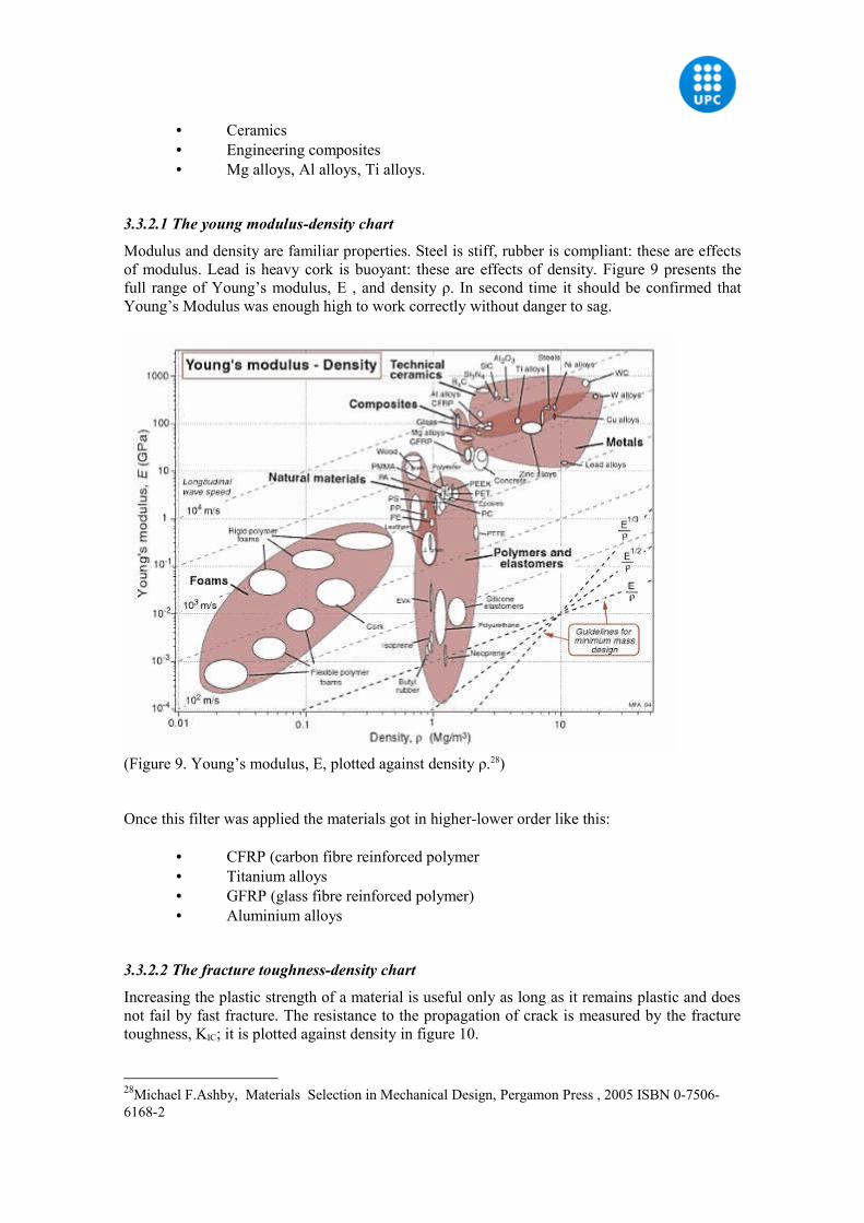
3.3.2.1 The young modulus-density chart
Modulus and density are familiar properties. Steel is stiff, rubber is compliant: these are effects of modulus. Lead is heavy cork is buoyant: these are effects of density. Figure 9 presents the full range of Young’s modulus, E , and density ρ. In second time it should be confirmed that Young’s Modulus was enough high to work correctly without danger to sag.
(Figure 9. Young’s modulus, E, plotted against density ρ.28)
Once this filter was applied the materials got in higher-lower order like this:
• CFRP (carbon fibre reinforced polymer• Titanium alloys• GFRP (glass fibre reinforced polymer)• Aluminium alloys
3.3.2.2 The fracture toughness-density chart
Increasing the plastic strength of a material is useful only as long as it remains plastic and does not fail by fast fracture. The resistance to the propagation of crack is measured by the fracture toughness, KIC; it is plotted against density in figure 10.
28Michael F.Ashby, Materials Selection in Mechanical Design, Pergamon Press , 2005 ISBN 0-7506-6168-2
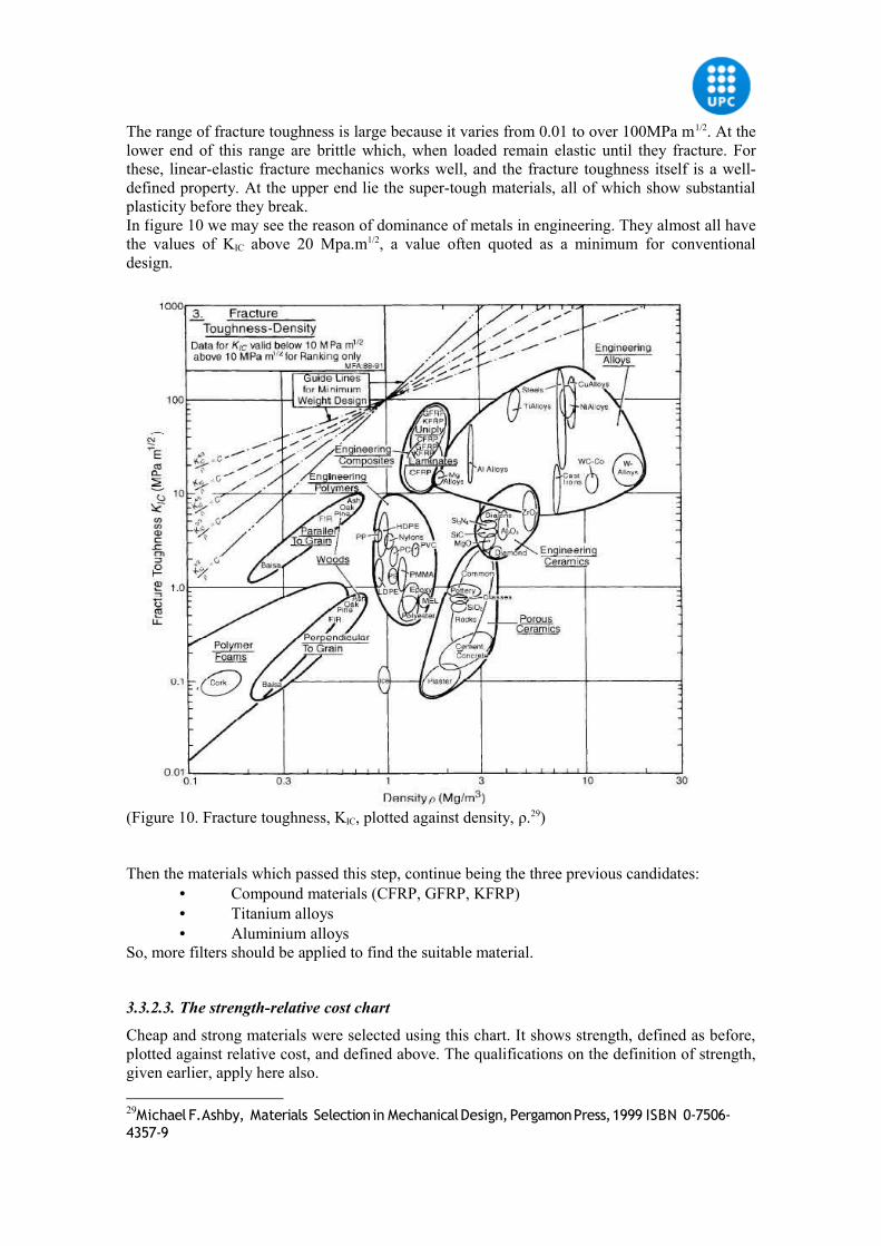
The range of fracture toughness is large because it varies from 0.01 to over 100MPa m1/2. At the lower end of this range are brittle which, when loaded remain elastic until they fracture. For these, linear-elastic fracture mechanics works well, and the fracture toughness itself is a well-defined property. At the upper end lie the super-tough materials, all of which show substantial plasticity before they break.In figure 10 we may see the reason of dominance of metals in engineering. They almost all have the values of KIC above 20 Mpa.m1/2, a value often quoted as a minimum for conventional design.
(Figure 10. Fracture toughness, KIC, plotted against density, ρ.29)
Then the materials which passed this step, continue being the three previous candidates:• Compound materials (CFRP, GFRP, KFRP)• Titanium alloys• Aluminium alloys
So, more filters should be applied to find the suitable material.
3.3.2.3. The strength-relative cost chart
Cheap and strong materials were selected using this chart. It shows strength, defined as before, plotted against relative cost, and defined above. The qualifications on the definition of strength, given earlier, apply here also.
29Michael F.Ashby, Materials Selection in Mechanical Design, Pergamon Press, 1999 ISBN 0-7506-4357-9
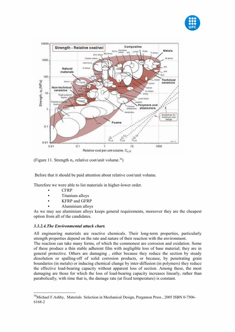
(Figure 11. Strength σf, relative cost/unit volume.30)
Before that it should be paid attention about relative cost/unit volume.
Therefore we were able to list materials in higher-lower order.• CFRP• Titanium alloys• KFRP and GFRP• Aluminium alloys
As we may see aluminium alloys keeps general requirements, moreover they are the cheapest option from all of the candidates.
3.3.2.4.The Environmental attack chart.
All engineering materials are reactive chemicals. Their long-term properties, particularly strength properties depend on the rate and nature of their reaction with the environment.The reaction can take many forms, of which the commonest are corrosion and oxidation. Some of these produce a thin stable adherent film with negligible loss of base material; they are in general protective. Others are damaging , either because they reduce the section by steady dissolution or spalling-off of solid corrosion products, or because, by penetrating grain boundaries (in metals) or inducing chemical change by inter-diffusion (in polymers) they reduce the effective load-bearing capacity without apparent loss of section. Among these, the most damaging are those for which the loss of load-bearing capacity increases linearly, rather than parabolically, with time that is, the damage rate (at fixed temperature) is constant.
30Michael F.Ashby, Materials Selection in Mechanical Design, Pergamon Press , 2005 ISBN 0-7506-6168-2
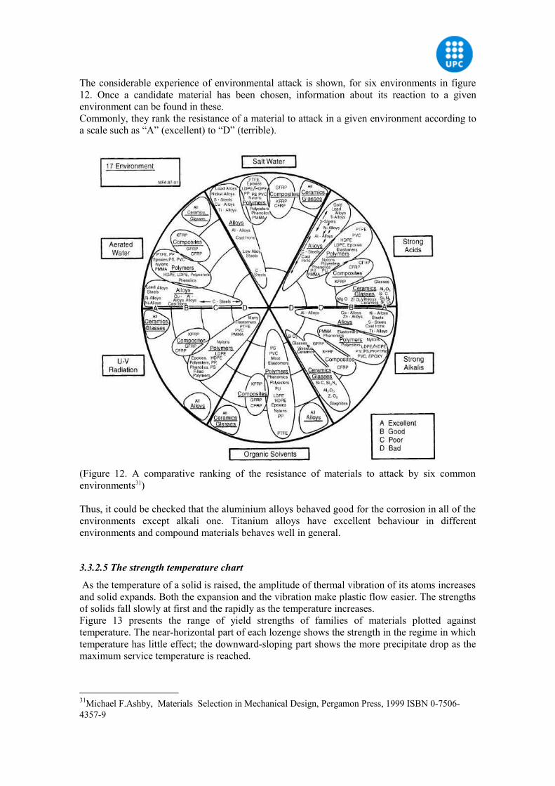
The considerable experience of environmental attack is shown, for six environments in figure 12. Once a candidate material has been chosen, information about its reaction to a given environment can be found in these.Commonly, they rank the resistance of a material to attack in a given environment according to a scale such as “A” (excellent) to “D” (terrible).
(Figure 12. A comparative ranking of the resistance of materials to attack by six common environments31) Thus, it could be checked that the aluminium alloys behaved good for the corrosion in all of the environments except alkali one. Titanium alloys have excellent behaviour in different environments and compound materials behaves well in general.
3.3.2.5 The strength temperature chart
As the temperature of a solid is raised, the amplitude of thermal vibration of its atoms increases and solid expands. Both the expansion and the vibration make plastic flow easier. The strengths of solids fall slowly at first and the rapidly as the temperature increases.Figure 13 presents the range of yield strengths of families of materials plotted against temperature. The near-horizontal part of each lozenge shows the strength in the regime in which temperature has little effect; the downward-sloping part shows the more precipitate drop as the maximum service temperature is reached.
31Michael F.Ashby, Materials Selection in Mechanical Design, Pergamon Press, 1999 ISBN 0-7506-4357-9
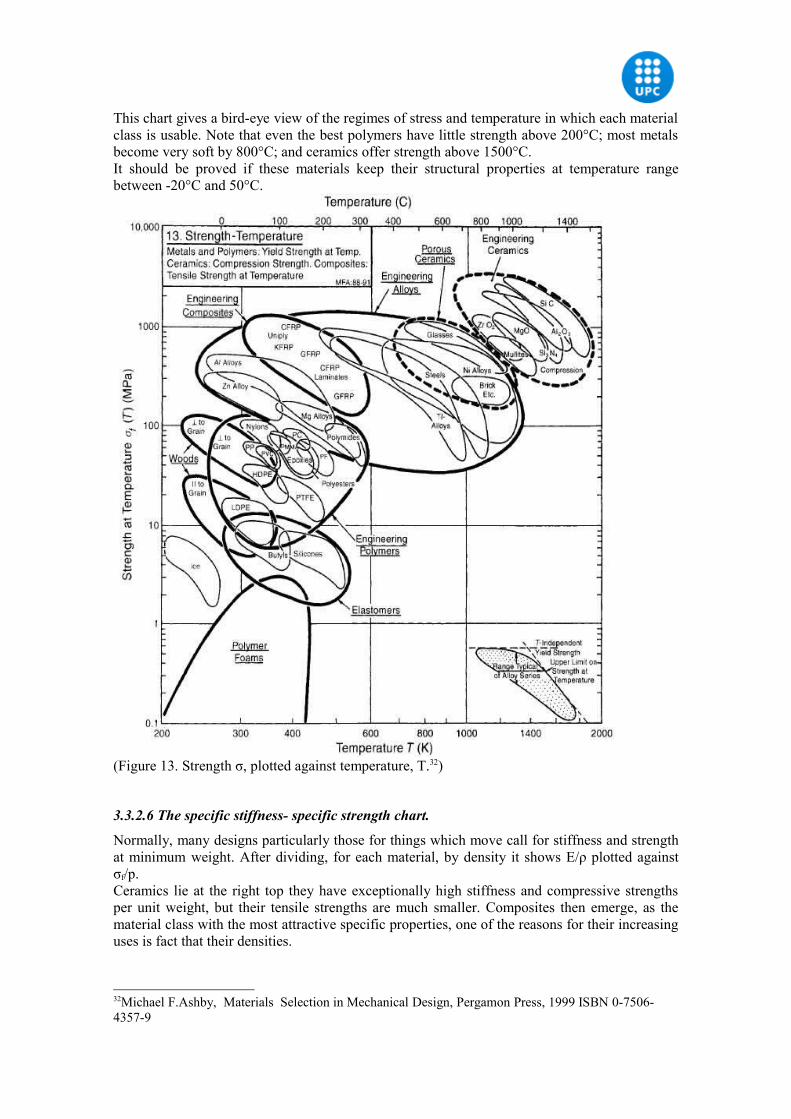
This chart gives a bird-eye view of the regimes of stress and temperature in which each material class is usable. Note that even the best polymers have little strength above 200°C; most metals become very soft by 800°C; and ceramics offer strength above 1500°C.It should be proved if these materials keep their structural properties at temperature range between -20°C and 50°C.
(Figure 13. Strength σ, plotted against temperature, T.32)
3.3.2.6 The specific stiffness- specific strength chart.
Normally, many designs particularly those for things which move call for stiffness and strength at minimum weight. After dividing, for each material, by density it shows E/ρ plotted against σf/p.Ceramics lie at the right top they have exceptionally high stiffness and compressive strengths per unit weight, but their tensile strengths are much smaller. Composites then emerge, as the material class with the most attractive specific properties, one of the reasons for their increasing uses is fact that their densities.
32Michael F.Ashby, Materials Selection in Mechanical Design, Pergamon Press, 1999 ISBN 0-7506-4357-9
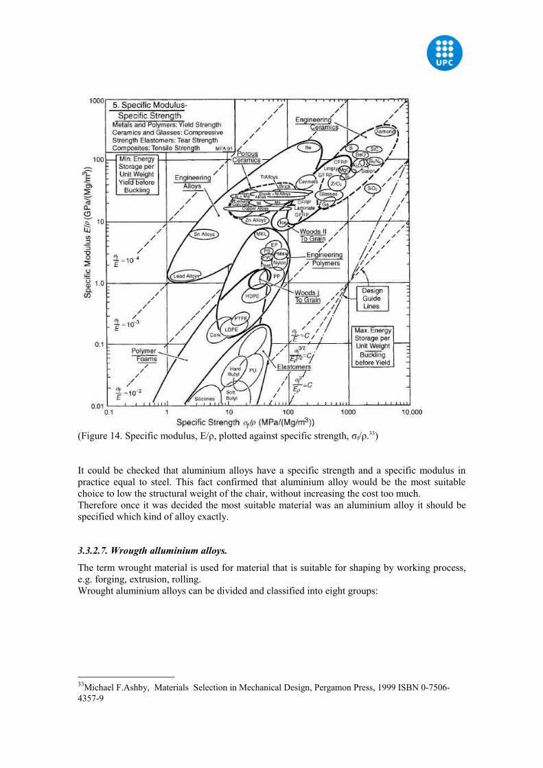
(Figure 14. Specific modulus, E/ρ, plotted against specific strength, σf/ρ.33)
It could be checked that aluminium alloys have a specific strength and a specific modulus in practice equal to steel. This fact confirmed that aluminium alloy would be the most suitable choice to low the structural weight of the chair, without increasing the cost too much.Therefore once it was decided the most suitable material was an aluminium alloy it should be specified which kind of alloy exactly.
3.3.2.7. Wrougth alluminium alloys.
The term wrought material is used for material that is suitable for shaping by working process, e.g. forging, extrusion, rolling.Wrought aluminium alloys can be divided and classified into eight groups:
33Michael F.Ashby, Materials Selection in Mechanical Design, Pergamon Press, 1999 ISBN 0-7506-4357-9
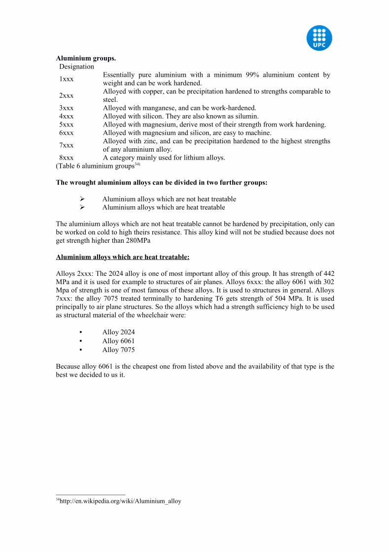
Aluminium groups.Designation
1xxx Essentially pure aluminium with a minimum 99% aluminium content by weight and can be work hardened.
2xxx Alloyed with copper, can be precipitation hardened to strengths comparable to steel.
3xxx Alloyed with manganese, and can be work-hardened.4xxx Alloyed with silicon. They are also known as silumin.5xxx Alloyed with magnesium, derive most of their strength from work hardening. 6xxx Alloyed with magnesium and silicon, are easy to machine.
7xxx Alloyed with zinc, and can be precipitation hardened to the highest strengths of any aluminium alloy.
8xxx A category mainly used for lithium alloys.(Table 6 aluminium groups34)
The wrought aluminium alloys can be divided in two further groups:
Aluminium alloys which are not heat treatable Aluminium alloys which are heat treatable
The aluminium alloys which are not heat treatable cannot be hardened by precipitation, only can be worked on cold to high theirs resistance. This alloy kind will not be studied because does not get strength higher than 280MPa
Aluminium alloys which are heat treatable:
Alloys 2xxx: The 2024 alloy is one of most important alloy of this group. It has strength of 442 MPa and it is used for example to structures of air planes. Alloys 6xxx: the alloy 6061 with 302 Mpa of strength is one of most famous of these alloys. It is used to structures in general. Alloys 7xxx: the alloy 7075 treated terminally to hardening T6 gets strength of 504 MPa. It is used principally to air plane structures. So the alloys which had a strength sufficiency high to be used as structural material of the wheelchair were:
• Alloy 2024• Alloy 6061• Alloy 7075
Because alloy 6061 is the cheapest one from listed above and the availability of that type is the best we decided to us it.
34http://en.wikipedia.org/wiki/Aluminium_alloy
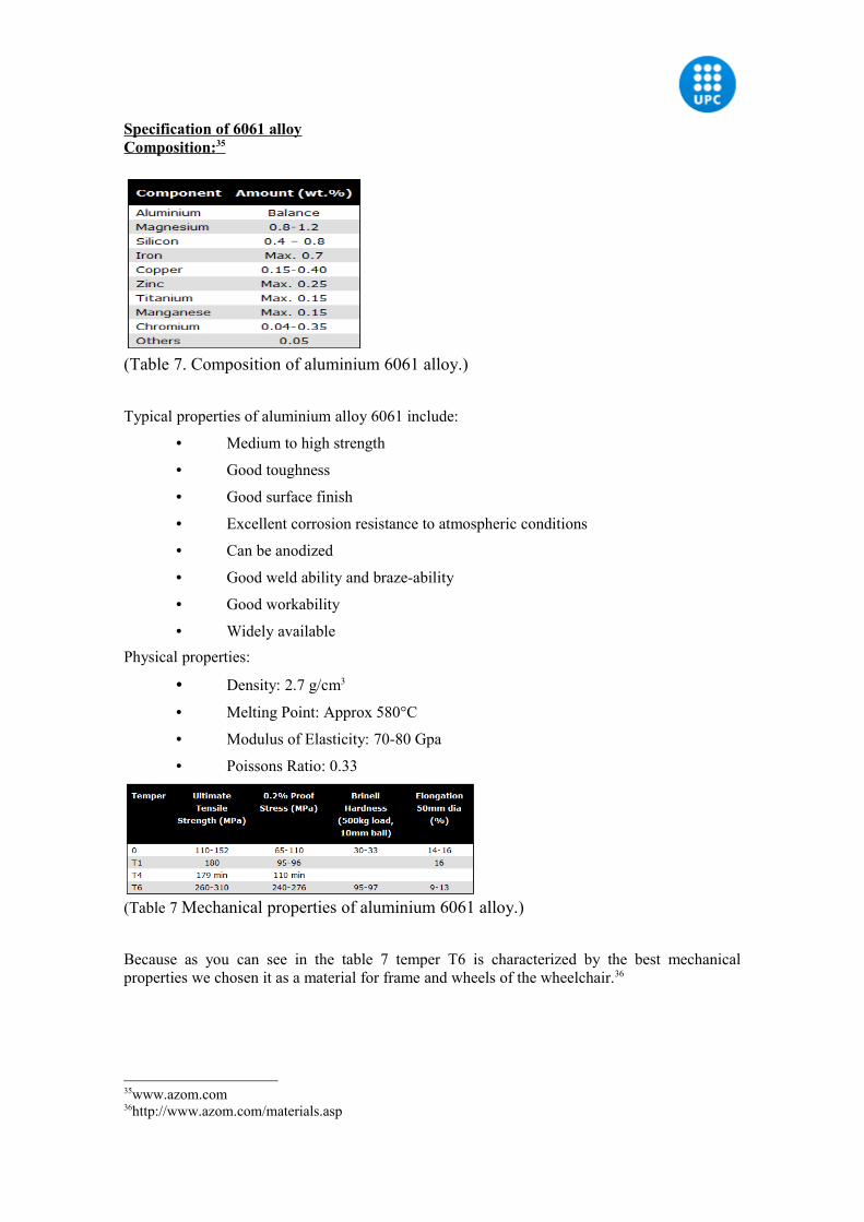
Specification of 6061 alloyComposition: 35
(Table 7. Composition of aluminium 6061 alloy.)
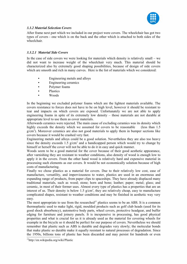
Typical properties of aluminium alloy 6061 include:
• Medium to high strength
• Good toughness
• Good surface finish
• Excellent corrosion resistance to atmospheric conditions
• Can be anodized
• Good weld ability and braze-ability
• Good workability
• Widely availablePhysical properties:
• Density: 2.7 g/cm3
• Melting Point: Approx 580°C
• Modulus of Elasticity: 70-80 Gpa
• Poissons Ratio: 0.33
(Table 7 Mechanical properties of aluminium 6061 alloy.)
Because as you can see in the table 7 temper T6 is characterized by the best mechanical properties we chosen it as a material for frame and wheels of the wheelchair.36
35www.azom.com36http://www.azom.com/materials.asp
3.3.2 Material Selection CoversAfter frame next part which we included in our project were covers. The wheelchair has got two types of covers - one which is on the back and the other which is attached to both sides of the wheelchair.
3.3.2.1 Material Side Covers
In the case of side covers we were looking for materials which density is relatively small – we did not want to increase weight of the wheelchair very much. This material should be characterized also by extremely good shaping possibilities, because of design of side covers which are smooth and rich in many curves. Here is the list of materials which we considered:
• Engineering metals and alloys• Engineering ceramics• Polymer foams• Plastics• Woods
In the beginning we excluded polymer foams which are the lightest materials available. The covers resistance to forces does not have to be on high level, however it should be resistant to tear and impacts on which covers are exposed. Unfortunately we are not able to apply engineering foams in spite of its extremely low density – those materials are not durable at appropriate level to use them as cover materials.Afterwards ceramics were rejected. The main cause of excluding ceramics was its density which highly exceeds the density which we assumed for covers to be reasonable (less than 1.5 g/cm3). Moreover ceramics are also not good materials to apply them in bumper sections like covers because it would be crashed very fast.Engineering metals and alloys could be a good solution. Nevertheless they are also too heavy since the density exceeds 1.5 g/cm3 and a handicapped person which would try to change by himself or herself the cover will not be able to do it in easy and quick manner.Woods seem to be a good material for the cover because of their good aesthetic appearance, after varnishing they are resistant to weather conditions, also density of wood is enough low to apply it in the covers. From the other hand wood is relatively hard and expensive material in processing such elements as our covers. It would be not economically solution because of high costs of manufacturing.Finally we chose plastics as a material for covers. Due to their relatively low cost, ease of manufacture, versatility, and imperviousness to water, plastics are used in an enormous and expanding range of products, from paper clips to spaceships. They have already displaced many traditional materials, such as wood; stone; horn and bone; leather; paper; metal; glass; and ceramic, in most of their former uses. Almost every type of plastics has a properties that are an interest of us. Their density is below 1.5 g/cm3, they are relatively cheap, easy to manufacture complicated shapes, resistant to weather conditions and may be finished in aesthetic way very easy.The most appropriate to use from the researched37 plastics seems to be an ABS. It is a common thermoplastic used to make light, rigid, moulded products such as golf club heads (used for its good shock absorbency), automotive body parts, wheel covers, protective headgear, and buffer edging for furniture and joinery panels. It is inexpensive in processing, has good physical properties and what is crucial for us it is already used as the material for covering wheels for example in the bicycle so it should be perfect for our purpose of covers. Nevertheless we should remember that plastic such as ABS is durable and degrades very slowly; the molecular bonds that make plastic so durable make it equally resistant to natural processes of degradation. Since the 1950s, billions tons of plastic has been discarded and may persist for hundreds or even 37http://en.wikipedia.org/wiki/Plastic
thousands of years. Moreover, burning plastic can release toxic fumes - dioxins. Also, the manufacturing of plastics often creates large quantities of chemical pollutants. Unfortunately, recycling of it is a complicated and not satisfying because of efficiency. The biggest problem is to automate the sorting of plastic wastes, making it labour intensive.We wanted to make our wheelchair as environmental friendly as it can be possible so we decided to look for an alternative for the ABS in order to achieve both – aesthetic, durable product and cover which production will not be harmful to the environment. Because covers displays only aesthetic role in our design it would be a huge waste of oil from which the plastic is produced to achieve just a good look. We searched for the alternative for common plastics and we found the Arboform®.The Arboform® is a new thermoplastic material made strictly from renewable resources. Composition of this material includes mainly lignin. It is a natural polymer which is formed by means of photosynthesis and stands about thirty percent of mass of every tree and every wood plant. Lignin is second to cellulose the most common natural polymer and, in the tree trunk for instance, forms a three-dimensional supporting structure around the cellulose fibres. Lignin gives natural, as-grown wood the necessary compressive strength, which cellulose cannot provide. The cellulose fibre can only provide tensile strength, which means a compound of natural fibres (cellulose) and lignin makes a material that, just like natural wood, can withstand tensile and compressive loads in combination. By changing the exact composition of Arboform®
both in terms of quality and quantity it is possible to adjust strength, rigidity, dimensional stability with varying temperatures, and other material properties so as to suit specific product requirements.The main component of Arboform® is a by-product of the paper making industry – lignin. About fifty million tones of lignin are produced in various pulping processes worldwide every year. Unfortunately so far it is not used in the production of any practical product, so over ninety five percent of lignin is incinerated just for energy production. It is a huge waste of such a practical and widely available material. Arboform® has the use of this waste. The composition of this material includes specific types of lignin mixed witch fibres from wood, sisal, hemp and other fibrous plants. However some natural additives are also present. This composition makes possible to process it at raised temperatures thanks to this, material is made of renewable resources in 100 %. Moreover the material can be made into mouldings, sections or panels on common plastics processing machinery, just in the same way as a petrochemical thermoplastic material. So there is no need of special equipment for processing Arboform®. That material as it was earlier mentioned mainly is based on renewable resources, thanks to that fact it offers a great alternative to synthetic petrochemical plastics. The fact that it is made in one hundred percent from renewable resources means that it can be disposed in incineration plants just like wood, without producing toxic fumes like in the case of plastics. Moreover it means that amount of carbon dioxide emitted to the atmosphere will be equal to the mass of carbon dioxide previously assimilated by plants from which Arboform® is produced. It provides to conclusion that flow of carbon dioxide is in the closed circle so there is no accumulation of carbon dioxide in the atmosphere. Moreover, it goes without saying that, given the appropriate surroundings, certain Arboform® formulations are compost-able or biodegradable, should local circumstances make incineration appear uneconomic. Because of that our product has a positive contribution to mitigation of greenhouse effect.As we can see in the figure 14 Arboform® is a tension-resistant material with comparison to other common plastics. The tensile stress properties of the material seem to be satisfactory for our purposes. Moreover if we want detailed characterization of Arboform® we should look in the table 2. Thermal properties of the material are satisfactory because material is stable in the range of temperatures in which wheelchair is used. As it was earlier mentioned this range includes temperatures between -20°C and 50°C. Mould shrinkage is also at negligible level so the manufacturing process will not be complicated – we may be sure that shape and dimensions applied in the moulding will be the same in the case of cover. Density is also at acceptable level of 1,3g/cm3 to 1,4g/cm3. Not without meaning is also fire performance of the material, hopefully
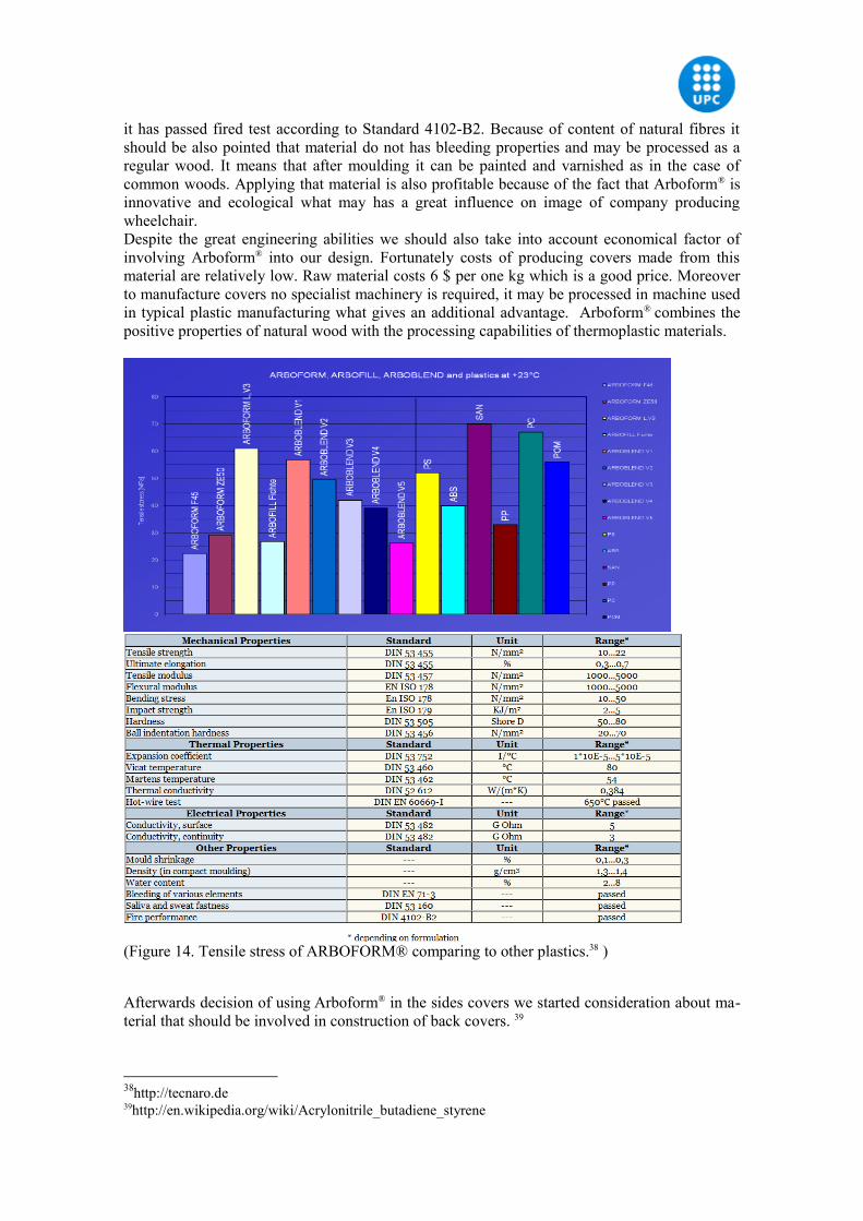
it has passed fired test according to Standard 4102-B2. Because of content of natural fibres it should be also pointed that material do not has bleeding properties and may be processed as a regular wood. It means that after moulding it can be painted and varnished as in the case of common woods. Applying that material is also profitable because of the fact that Arboform® is innovative and ecological what may has a great influence on image of company producing wheelchair.Despite the great engineering abilities we should also take into account economical factor of involving Arboform® into our design. Fortunately costs of producing covers made from this material are relatively low. Raw material costs 6 $ per one kg which is a good price. Moreover to manufacture covers no specialist machinery is required, it may be processed in machine used in typical plastic manufacturing what gives an additional advantage. Arboform® combines the positive properties of natural wood with the processing capabilities of thermoplastic materials.
(Figure 14. Tensile stress of ARBOFORM® comparing to other plastics.38 )
Afterwards decision of using Arboform® in the sides covers we started consideration about ma-terial that should be involved in construction of back covers. 39
38http://tecnaro.de39http://en.wikipedia.org/wiki/Acrylonitrile_butadiene_styrene
3.3.2.2 Back Cover
The structure of the wheelchair was designed in order to maintain foldable capability so the back cover should also make possible to fold the wheelchair. The cover should be made of material that is flexible, elastic, durable, easy to paint or stain in a desired colour. From the other hand it is supposed to be also a protector of an engine from mud, rain and other weather conditions so being waterproof is also desired. To do not loose time for long-lasting analysis we focused on trying to find on the market product already present which with some small modification may be applied as a such cover. Combining all of these features we assumed that similar properties has got a shower curtain what became our starting point. Most of the shower curtains present on the market are made of PVC, however it should be mentioned that curtains made from PVC are very dangerous because the fabric includes many poisonous substances like chlorine. Chlorine is the source of many of the environmental health concerns with PVC, such as the generation of dioxin, a highly carcinogenic chemical produced in both the manufacture and disposal of PVC. Due to their persistent and bioaccumulative nature (it travels long distances without breaking down and concentrates as it moves up the food chain to humans) dioxins have become a global problem and an international treaty – the Stockholm Convention on persistent organic pollutants (POPs) - now prioritizes the elimination of processes that produce dioxin. Fortunately there is a safe, ecological and environmental friendly alternative to PVC. It is called PEVA - a chlorine-free substitute for plastics made of PVC that is less harmful.By applying PEVA we obtained cover that may be easy attached and taken off from the frame by use of press studs. It is completely water resistant. Moreover it is not easy to tear such a material so it makes covers durable. Thanks to water resistance it protects engine from external factors like rain or mud. When it becomes dirty may be quickly washed with water without addition of any detergent. In addition it is flexible so the wheelchair may be folded without any problems. Staining and painting it is also effortless and cheap just as in the case of polyvinyl chloride. Price of the ready to use cover should not exceed 8€.40
3.3.2.3 Material Rain Cover
Rain cover fabricOne of the innovations applied in our design was a rain cover. As a market research and survey revealed people pointed weather conditions as a second obstacle in using wheelchair just after barriers that are in the urban terrain like steps. In order to meet needs of our future consumers we designed the rain cover.As name indicates rain cover should protect user from rain, snow and also from mud. Moreover we wanted to make rain cover durable. The material for that part of design should be a fabric which is mainly waterproof. We decided that both in the shape and role and it is almost the same as in the case on tents canopies. For that purpose mostly the synthetic fabrics are used. Because synthetic fabrics cannot protect efficiently from the water they are usually coated with many various specimens. The most popular material used to coat fabrics in case of tent production is PVC. However we avoided using PVC in the case of back covers because of its harmful impact on human health and environment so in that case we decided to use another material. Moreover coating polyester with PVC would effect in huge raise in weight of the material. Such a solution is mainly applied in bigger static tents which do not have to be put up frequently.Knowing that fabrics we need should be strong enough to withstand wind, resistant to rotting and microbes, and also UV resistant (it may be used not only as a rain cover but also as a wind cover when weather is sunny). We made a selection from material used to produce canopy according to its characteristics.
40Walter Fung , Coated and Laminated Textiles , Boca Raton ,2002, ISBN 0-8493-1448-7
We distinguished:
• Nylon• Acrylic fibres• Polyester
All of the listed materials are resistant to rotting and microbes. The differences in the density are so slight that may be omitted. However there are some other differentiating factors.Nylon has not got good resistance to UV degradation; nevertheless it may be improved by additives applied in dye bath and by careful dye selection. Unfortunately we did not want to be limited in dye selection because we need to be sure that colour of the rain cover fits perfectly to colour of side and back covers (which may vary a lot). There cannot be any restriction in application of any dye. The best UV resistance has got acrylic fibres but generally is not strong enough for our purpose. Polyester finished with a silicone water-repellent seems to be one the best choice. It has good UV resistance and is strong enough. However to make it completely waterproof we should apply coating from polyurethane. We also took into account wax finished cotton produced by paddling but in that case weight of this material appeared to high.41
Rain cover frame:Apart from fabric a rain cover is also build from the frame on which the fabric is put. Just the same as in the case of choosing fabric we oriented our research on things that are actually on the market to look for the most optimal set of materials that may be potentially used. We found that in tents to which our rain cover has a analogical construction there are used 3 types of materials in construction of frames:
• Fibreglass• Aluminium alloys• Carbon fibre
Usually the fibreglass which is used in production of tent frames is a combination of polyester and vinylester. It is relatively heavy and is definitely less reluctant to strengths than aluminium. Form the other hand it is characterized by huge elasticity and low price (that is the reason why it is so popular). Some of them like for example Durapole, Durawrap and Powerflex are covered with special film which role is to increase mechanical properties without increasing weight in noticed extend. In the case of tube rupture it does not dissect on the entire length but only at the fracture site, thus it can be easily secured and continue using it without a risk of damage to the rain cover.Pure aluminium is almost 3 times less dense than steel and is also worse because of mechanical features. However thanks to adding various compounds some alloys which characteristic is highly better than pure aluminium may be obtained. Aluminium alloys have got from 2,5 to 5 times better strength resistance and from 4 to 9 times higher yield strength resistance. In the tent poles the most common material that is use is aluminium alloy 7001 and 7075 which are the best compromise between weight, strength resistance, elasticity and price. Aluminium alloys components are from 15% to 20% times lighter than fibreglass tubes used in tents.Carbon fibre is the newest invention. It is far better than fibreglass and aluminium alloys – it is more elastic, durable, lighter (30 % lighter than aluminium alloy 7075-T9) and unfortunately also more expensive. The price of this material is three times bigger than in the case of aluminium alloy. It makes not possible to apply that material in our project.We decided to apply fibreglass for the rain cover frame because of fact that we do not want to make the rain cover extremely expensive what could happened if we had applied carbon fibre. We also rejected aluminium alloys because of problems with elasticity of that material. Aluminium alloy would require lots of strength to twist it and put rain cover into a bag. The
41Walter Fung , Coated and Laminated Textiles , Boca Raton ,2002, ISBN 0-8493-1448-7
most optimal choice seems to be fibre glass which weight is the biggest from listed above materials but the amount of material used in the design allows us to choose cheaper alternative despite of its relatively high weight. The mechanical properties of it are also satisfying for us – the compromise between price and performance was achieved.
3.3.3 Material Selection Barrier supply systemAt the end we must remember even about the smallest parts of wheelchair such as foot of barrier supply system. A material for such a purpose should be elastic to some extend, durable and should protect the bar from slipping. Without any complicated studies we may suspect that a threaded rubber will be a perfect solu-tion for such purpose. It is elastic to some extend but also enough durable to make the barrier supplier system work properly. For the exact material we suggest styrene-butadiene-rubber which is a synthetic rubber copolymer consisting of styrene and butadiene. It has good abrasion resistance and good ageing stability when protected by additives. To the most common applica-tion of this material we may count car tires, where it is blended with natural rubber. In our case it is also required adding natural rubber to make plug a little bit more elastic and softer.
3.4 InstallationIn this section the installation of the different parts is explained. The wheelchair is divided into four main sets. Wheelchair set 1, 2, 3 and 4. Every set has different assembly groups. Every set is part of the next set. After set 1 is built, this is used further where in set 2 different parts are added to the already finished set. Then set 2 is used to finish set 3. The wheelchair is finished in set 4. Every part has a number(_), this number is the reference to the mechanical drawing. In the Appendix 5 there is a list of every single part used for the wheelchair.
3.4.1 Wheelchair set 1 This set contains the assembly groups: Barrier supply system, two front wheels, two footrests, mirror, frame right, frame left, seat and back rest.After assembling the single parts, at the end the left and right frame are joint together with the seat and backrest.
3.4.1.1 Barrier supply system
Assembly Group 1 (BG1) is the barrier supply system, which is made up of: buffer(1), stilt(2), guiding bolts(3), case(4), channel blocker(5) and hand gear(6) with hand grip(7). To assemble the different parts one M8 lens head screw(10), one M8 nut(11), two thrust washer(12), two discs d=5(13), two nuts(14) and three discs d=8(15) are used.
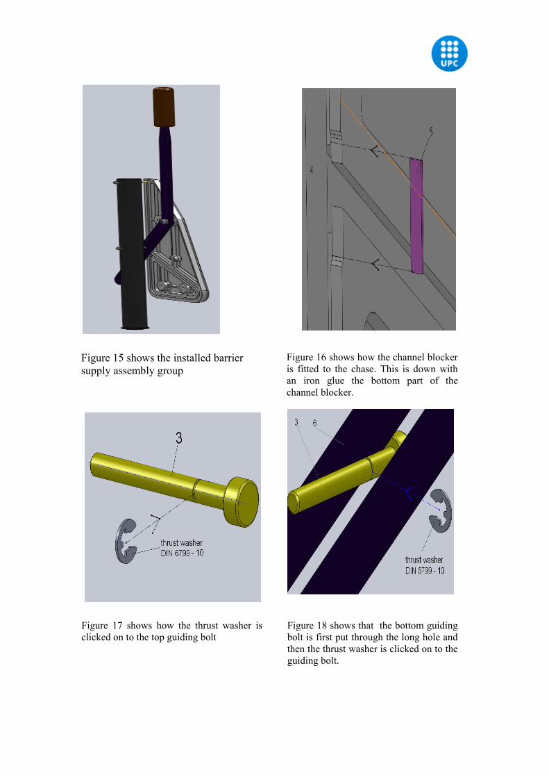
Figure 15 shows the installed barrier supply assembly group
Figure 16 shows how the channel blocker is fitted to the chase. This is down with an iron glue the bottom part of the channel blocker.
Figure 17 shows how the thrust washer is clicked on to the top guiding bolt
Figure 18 shows that the bottom guiding bolt is first put through the long hole and then the thrust washer is clicked on to the guiding bolt.
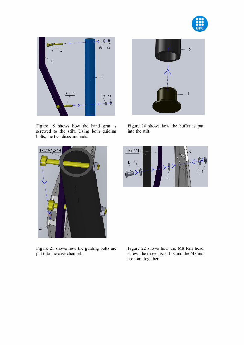
Figure 19 shows how the hand gear is screwed to the stilt. Using both guiding bolts, the two discs and nuts.
Figure 20 shows how the buffer is put into the stilt.
Figure 21 shows how the guiding bolts are put into the case channel.
Figure 22 shows how the M8 lens head screw, the three discs d=8 and the M8 nut are joint together.
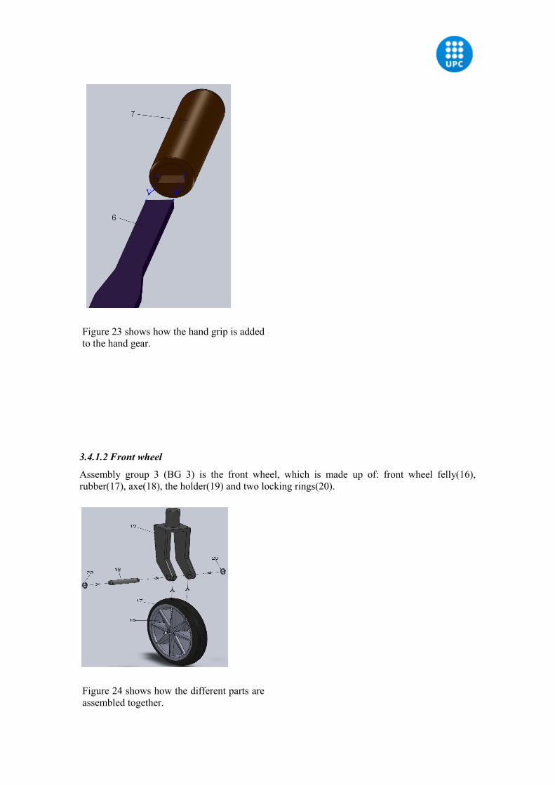
Figure 23 shows how the hand grip is added to the hand gear.
3.4.1.2 Front wheel
Assembly group 3 (BG 3) is the front wheel, which is made up of: front wheel felly(16), rubber(17), axe(18), the holder(19) and two locking rings(20).
Figure 24 shows how the different parts are assembled together.
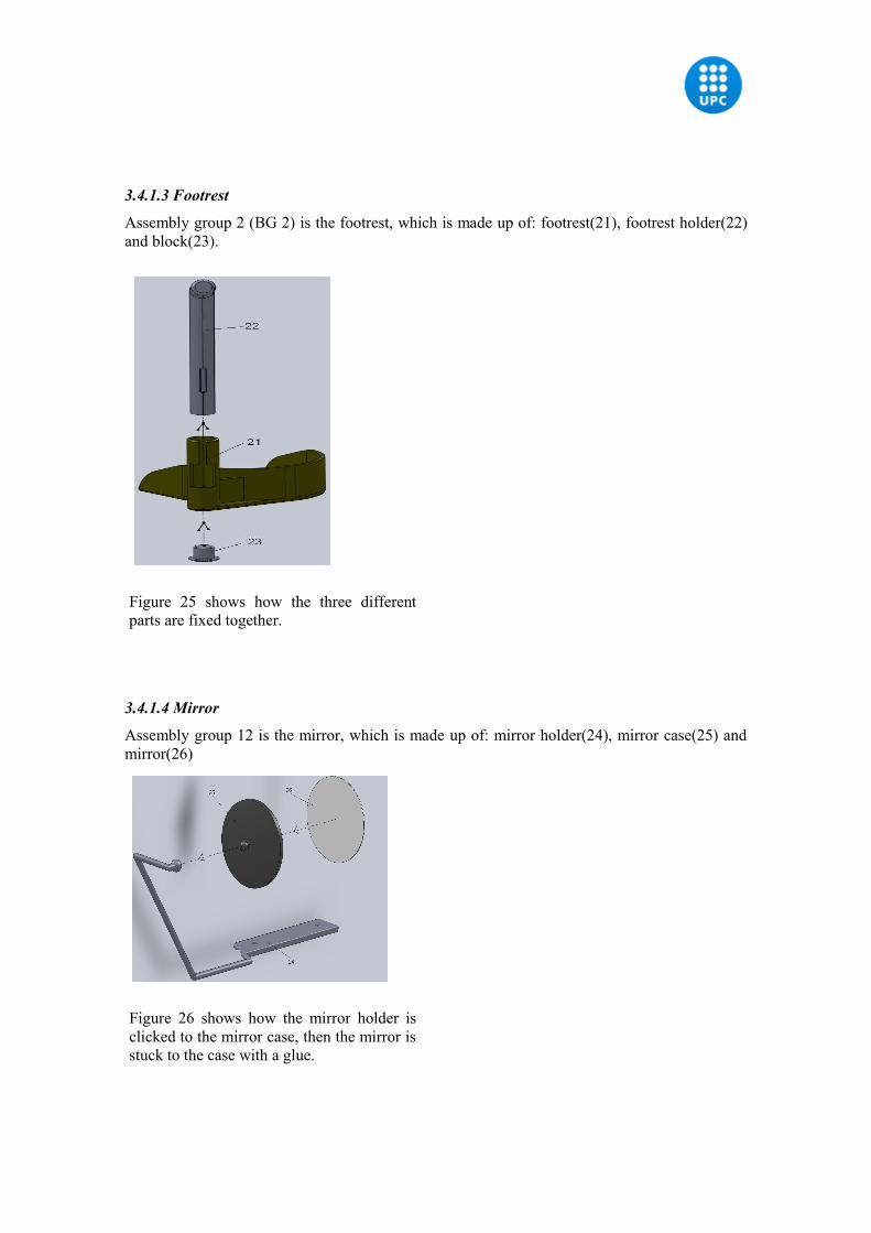
3.4.1.3 Footrest
Assembly group 2 (BG 2) is the footrest, which is made up of: footrest(21), footrest holder(22) and block(23).
Figure 25 shows how the three different parts are fixed together.
3.4.1.4 Mirror
Assembly group 12 is the mirror, which is made up of: mirror holder(24), mirror case(25) and mirror(26)
Figure 26 shows how the mirror holder is clicked to the mirror case, then the mirror is stuck to the case with a glue.
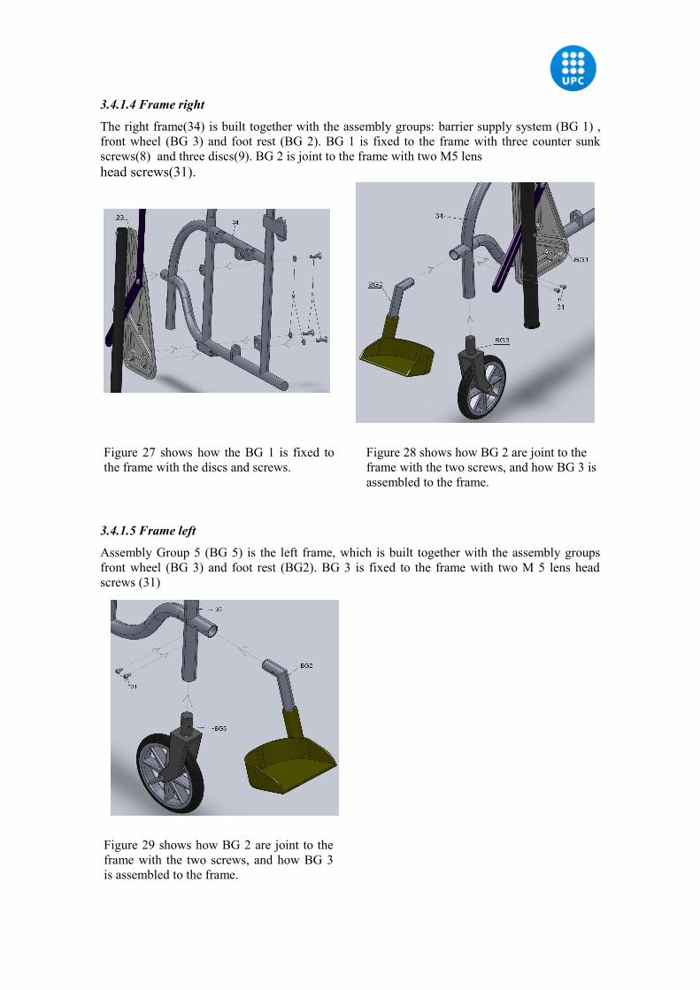
3.4.1.4 Frame right
The right frame(34) is built together with the assembly groups: barrier supply system (BG 1) , front wheel (BG 3) and foot rest (BG 2). BG 1 is fixed to the frame with three counter sunk screws(8) and three discs(9). BG 2 is joint to the frame with two M5 lens head screws(31).
Figure 27 shows how the BG 1 is fixed to the frame with the discs and screws.
Figure 28 shows how BG 2 are joint to the frame with the two screws, and how BG 3 is assembled to the frame.
3.4.1.5 Frame left
Assembly Group 5 (BG 5) is the left frame, which is built together with the assembly groups front wheel (BG 3) and foot rest (BG2). BG 3 is fixed to the frame with two M 5 lens head screws (31)
Figure 29 shows how BG 2 are joint to the frame with the two screws, and how BG 3 is assembled to the frame.
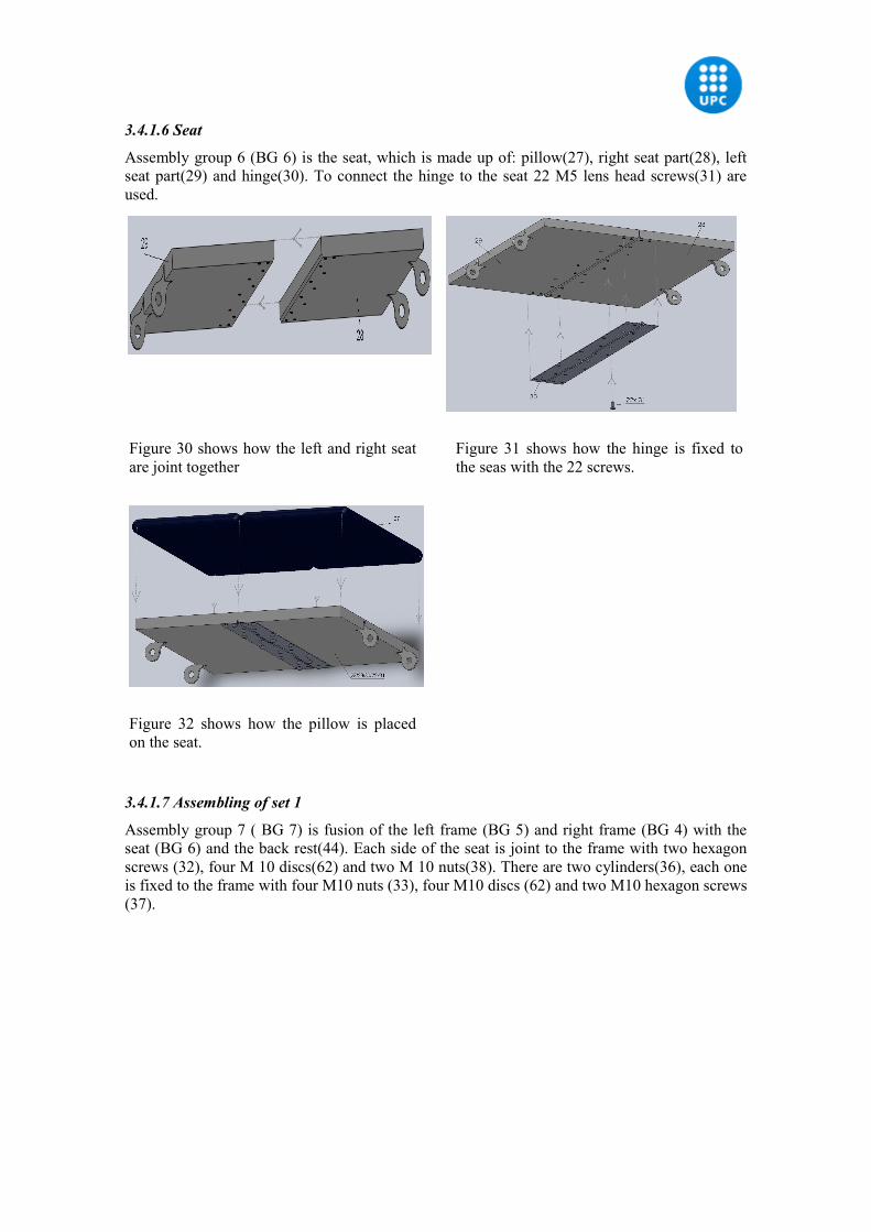
3.4.1.6 Seat
Assembly group 6 (BG 6) is the seat, which is made up of: pillow(27), right seat part(28), left seat part(29) and hinge(30). To connect the hinge to the seat 22 M5 lens head screws(31) are used.
Figure 30 shows how the left and right seat are joint together
Figure 31 shows how the hinge is fixed to the seas with the 22 screws.
Figure 32 shows how the pillow is placed on the seat.
3.4.1.7 Assembling of set 1
Assembly group 7 ( BG 7) is fusion of the left frame (BG 5) and right frame (BG 4) with the seat (BG 6) and the back rest(44). Each side of the seat is joint to the frame with two hexagon screws (32), four M 10 discs(62) and two M 10 nuts(38). There are two cylinders(36), each one is fixed to the frame with four M10 nuts (33), four M10 discs (62) and two M10 hexagon screws (37).
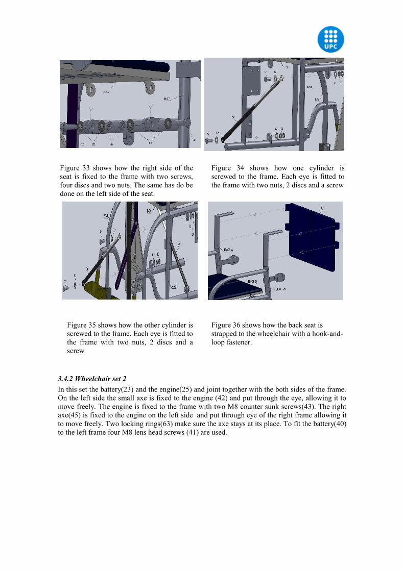
Figure 33 shows how the right side of the seat is fixed to the frame with two screws, four discs and two nuts. The same has do be done on the left side of the seat.
Figure 34 shows how one cylinder is screwed to the frame. Each eye is fitted to the frame with two nuts, 2 discs and a screw
Figure 35 shows how the other cylinder is screwed to the frame. Each eye is fitted to the frame with two nuts, 2 discs and a screw
Figure 36 shows how the back seat is strapped to the wheelchair with a hook-and-loop fastener.
3.4.2 Wheelchair set 2In this set the battery(23) and the engine(25) and joint together with the both sides of the frame. On the left side the small axe is fixed to the engine (42) and put through the eye, allowing it to move freely. The engine is fixed to the frame with two M8 counter sunk screws(43). The right axe(45) is fixed to the engine on the left side and put through eye of the right frame allowing it to move freely. Two locking rings(63) make sure the axe stays at its place. To fit the battery(40) to the left frame four M8 lens head screws (41) are used.
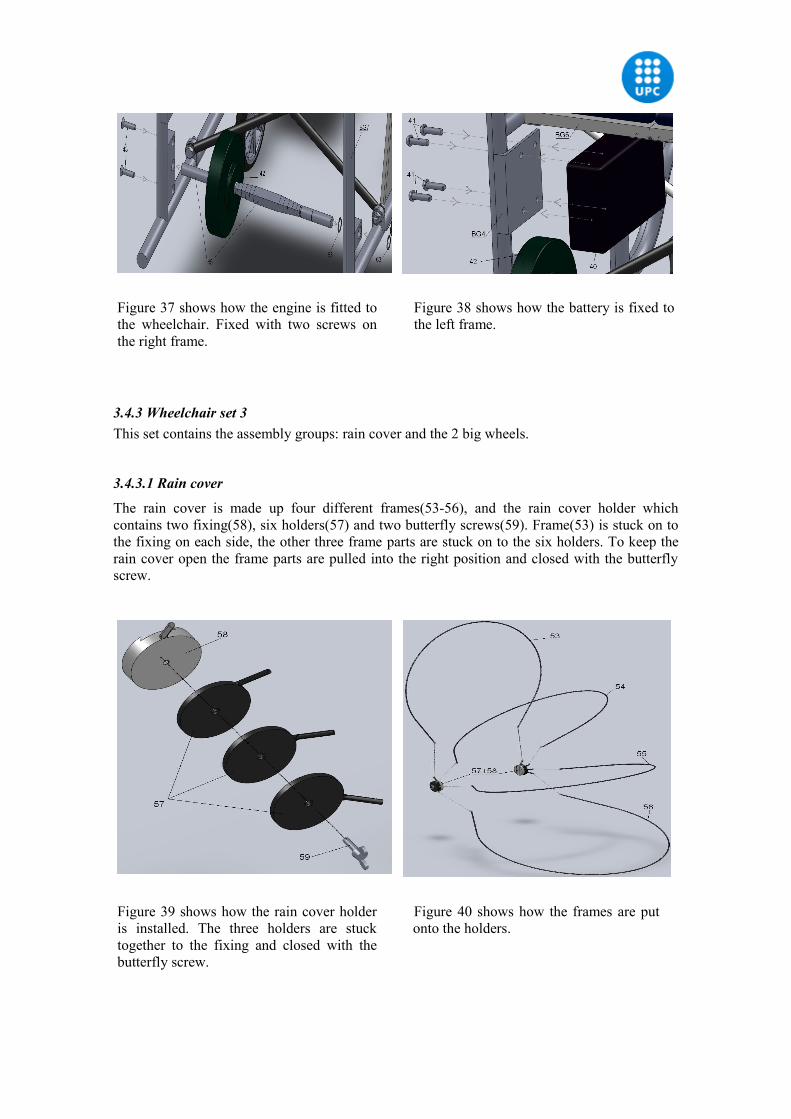
Figure 37 shows how the engine is fitted to the wheelchair. Fixed with two screws on the right frame.
Figure 38 shows how the battery is fixed to the left frame.
3.4.3 Wheelchair set 3This set contains the assembly groups: rain cover and the 2 big wheels.
3.4.3.1 Rain cover
The rain cover is made up four different frames(53-56), and the rain cover holder which contains two fixing(58), six holders(57) and two butterfly screws(59). Frame(53) is stuck on to the fixing on each side, the other three frame parts are stuck on to the six holders. To keep the rain cover open the frame parts are pulled into the right position and closed with the butterfly screw.
Figure 39 shows how the rain cover holder is installed. The three holders are stuck together to the fixing and closed with the butterfly screw.
Figure 40 shows how the frames are put onto the holders.
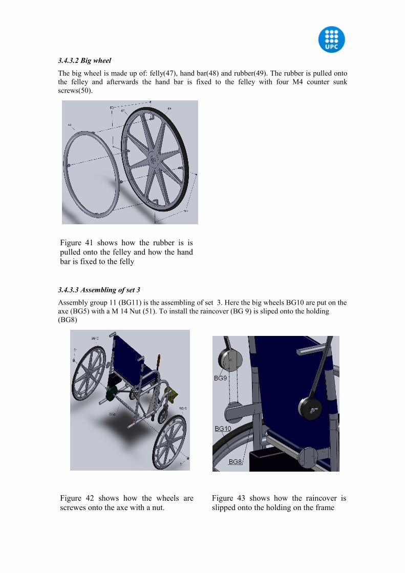
3.4.3.2 Big wheel
The big wheel is made up of: felly(47), hand bar(48) and rubber(49). The rubber is pulled onto the felley and afterwards the hand bar is fixed to the felley with four M4 counter sunk screws(50).
Figure 41 shows how the rubber is is pulled onto the felley and how the hand bar is fixed to the felly
3.4.3.3 Assembling of set 3
Assembly group 11 (BG11) is the assembling of set 3. Here the big wheels BG10 are put on the axe (BG5) with a M 14 Nut (51). To install the raincover (BG 9) is sliped onto the holding (BG8)
Figure 42 shows how the wheels are screwes onto the axe with a nut.
Figure 43 shows how the raincover is slipped onto the holding on the frame
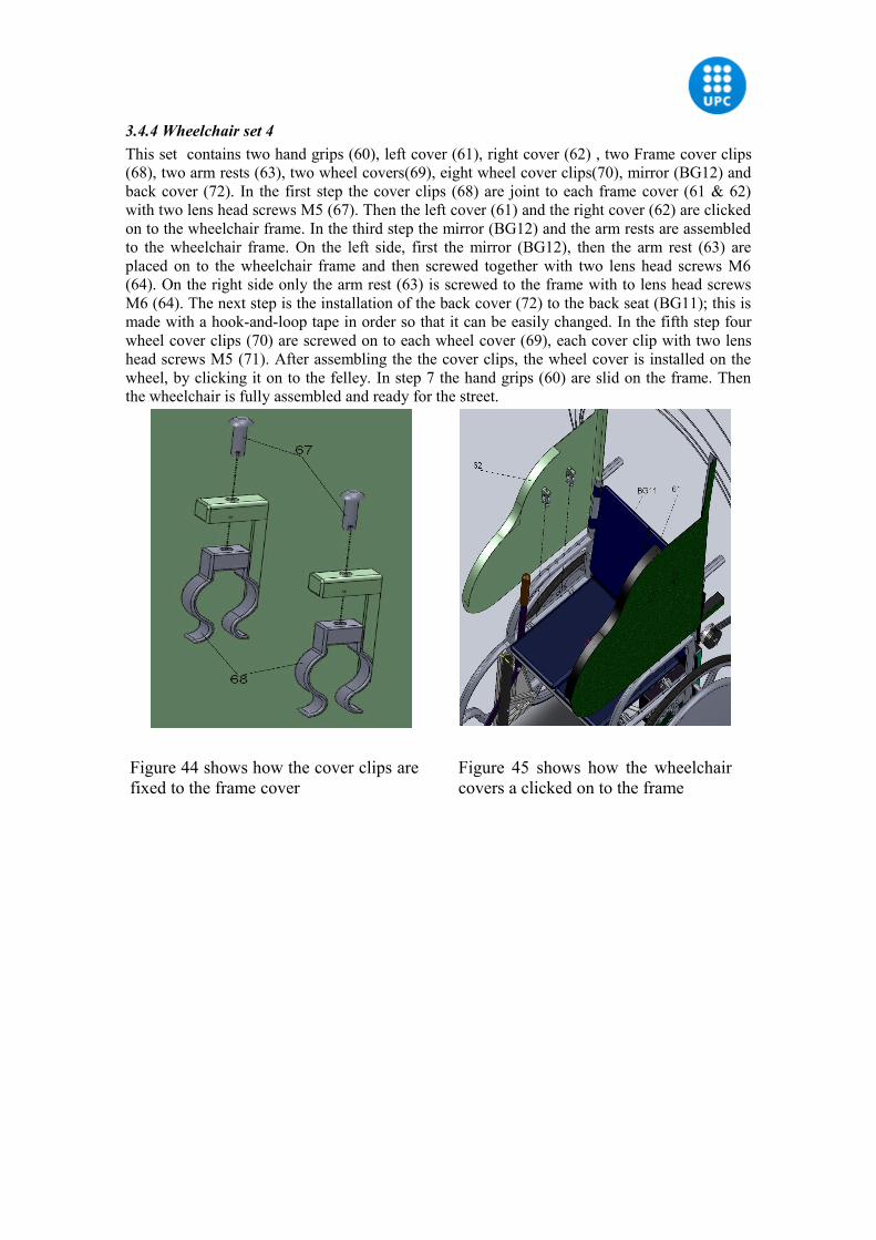
3.4.4 Wheelchair set 4This set contains two hand grips (60), left cover (61), right cover (62) , two Frame cover clips (68), two arm rests (63), two wheel covers(69), eight wheel cover clips(70), mirror (BG12) and back cover (72). In the first step the cover clips (68) are joint to each frame cover (61 & 62) with two lens head screws M5 (67). Then the left cover (61) and the right cover (62) are clicked on to the wheelchair frame. In the third step the mirror (BG12) and the arm rests are assembled to the wheelchair frame. On the left side, first the mirror (BG12), then the arm rest (63) are placed on to the wheelchair frame and then screwed together with two lens head screws M6 (64). On the right side only the arm rest (63) is screwed to the frame with to lens head screws M6 (64). The next step is the installation of the back cover (72) to the back seat (BG11); this is made with a hook-and-loop tape in order so that it can be easily changed. In the fifth step four wheel cover clips (70) are screwed on to each wheel cover (69), each cover clip with two lens head screws M5 (71). After assembling the the cover clips, the wheel cover is installed on the wheel, by clicking it on to the felley. In step 7 the hand grips (60) are slid on the frame. Then the wheelchair is fully assembled and ready for the street.
Figure 44 shows how the cover clips are fixed to the frame cover
Figure 45 shows how the wheelchair covers a clicked on to the frame
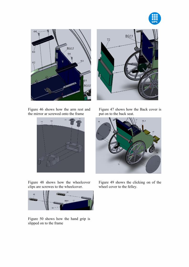
Figure 46 shows how the arm rest and the mirror ar screwed onto the frame
Figure 47 shows how the Back cover is put on to the back seat.
Figure 48 shows how the wheelcover clips are screwes to the wheelcover.
Figure 49 shows the clicking on of the wheel cover to the felley.
Figure 50 shows how the hand grip is slipped on to the frame
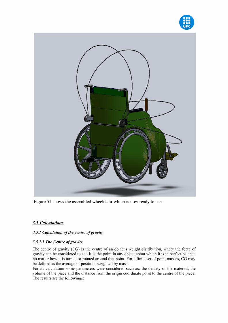
Figure 51 shows the assembled wheelchair which is now ready to use.
3.5 Calculations
3.5.1 Calculation of the centre of gravity
3.5.1.1 The Centre of gravity
The centre of gravity (CG) is the centre of an object's weight distribution, where the force of gravity can be considered to act. It is the point in any object about which it is in perfect balance no matter how it is turned or rotated around that point. For a finite set of point masses, CG may be defined as the average of positions weighted by mass. For its calculation some parameters were considered such as: the density of the material, the volume of the piece and the distance from the origin coordinate point to the centre of the piece. The results are the followings:
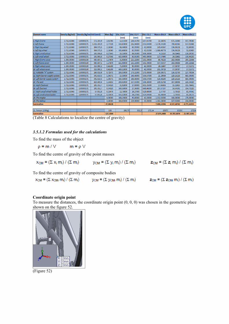
(Table 8 Calculations to localize the centre of gravity)
3.5.1.2 Formulas used for the calculations
To find the mass of the object
To find the centre of gravity of the point masses
To find the centre of gravity of composite bodies
Coordinate origin pointTo measure the distances, the coordinate origin point (0, 0, 0) was chosen in the geometric place shown on the figure 52.
(Figure 52)
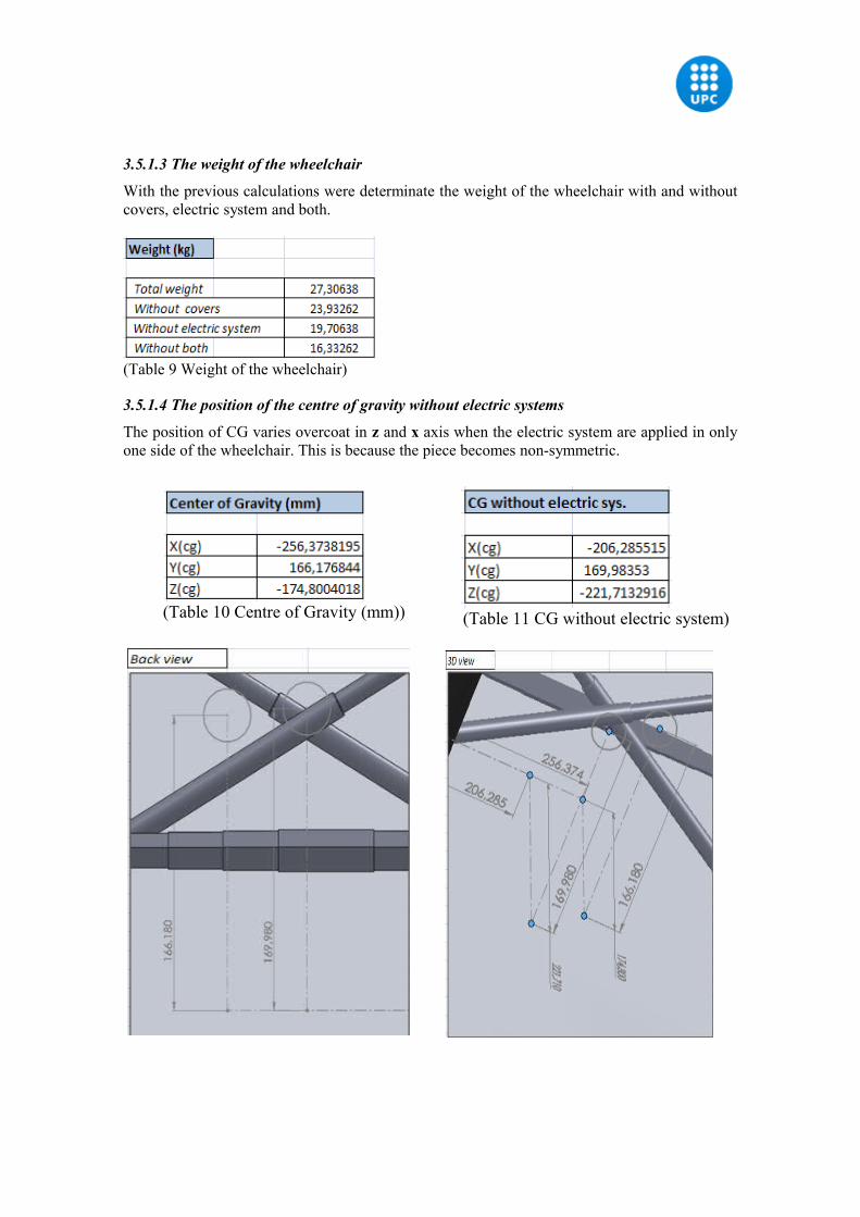
3.5.1.3 The weight of the wheelchair
With the previous calculations were determinate the weight of the wheelchair with and without covers, electric system and both.
(Table 9 Weight of the wheelchair)
3.5.1.4 The position of the centre of gravity without electric systems
The position of CG varies overcoat in z and x axis when the electric system are applied in only one side of the wheelchair. This is because the piece becomes non-symmetric.
(Table 10 Centre of Gravity (mm)) (Table 11 CG without electric system)
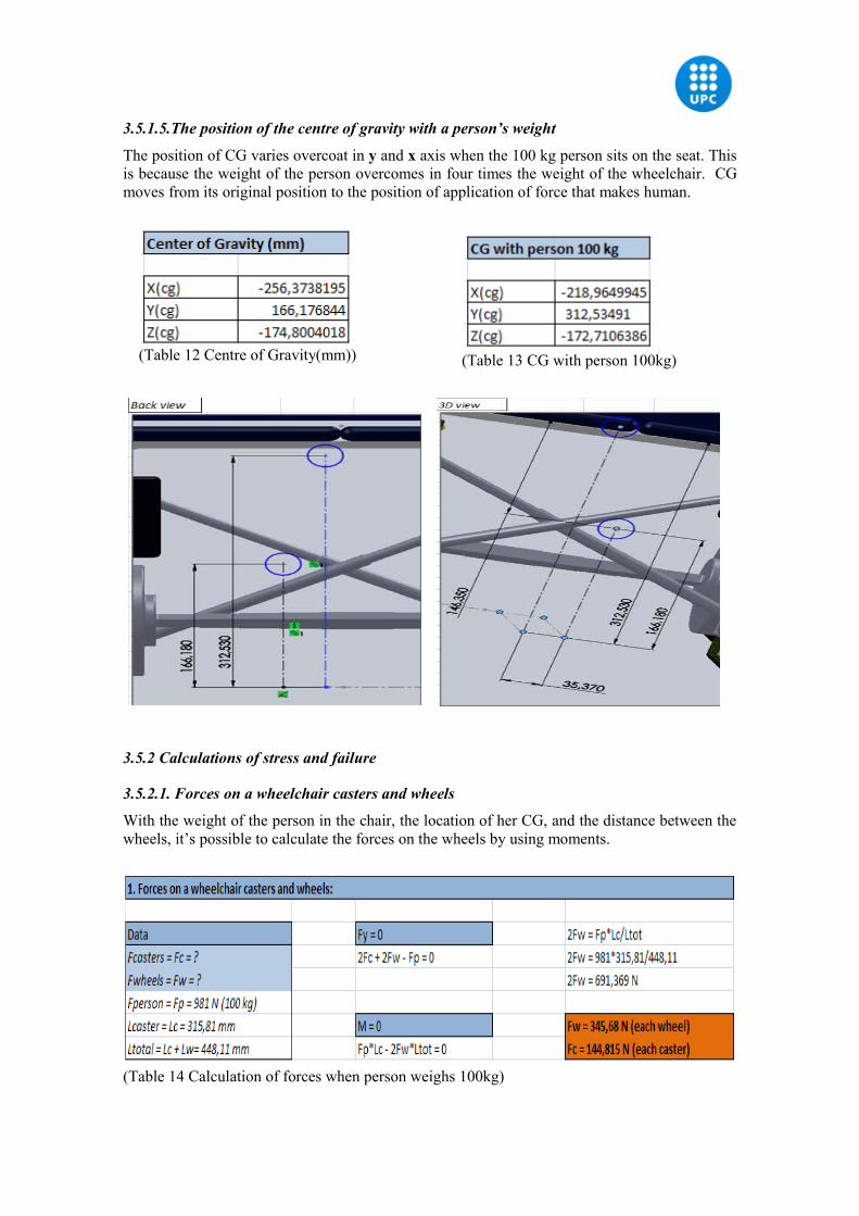
3.5.1.5.The position of the centre of gravity with a person’s weight
The position of CG varies overcoat in y and x axis when the 100 kg person sits on the seat. This is because the weight of the person overcomes in four times the weight of the wheelchair. CG moves from its original position to the position of application of force that makes human.
(Table 12 Centre of Gravity(mm)) (Table 13 CG with person 100kg)
3.5.2 Calculations of stress and failure
3.5.2.1. Forces on a wheelchair casters and wheels
With the weight of the person in the chair, the location of her CG, and the distance between the wheels, it’s possible to calculate the forces on the wheels by using moments.
(Table 14 Calculation of forces when person weighs 100kg)
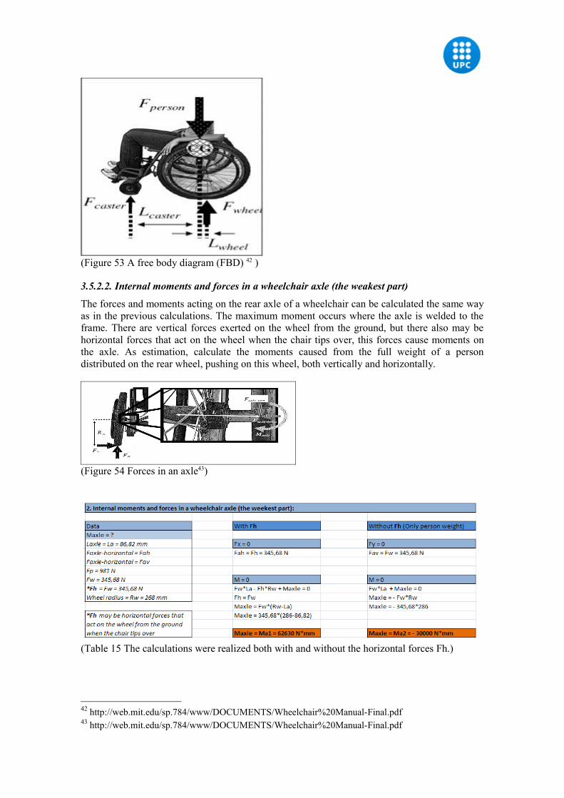
(Figure 53 A free body diagram (FBD) 42 )
3.5.2.2. Internal moments and forces in a wheelchair axle (the weakest part)
The forces and moments acting on the rear axle of a wheelchair can be calculated the same way as in the previous calculations. The maximum moment occurs where the axle is welded to the frame. There are vertical forces exerted on the wheel from the ground, but there also may be horizontal forces that act on the wheel when the chair tips over, this forces cause moments on the axle. As estimation, calculate the moments caused from the full weight of a person distributed on the rear wheel, pushing on this wheel, both vertically and horizontally.
(Figure 54 Forces in an axle43)
(Table 15 The calculations were realized both with and without the horizontal forces Fh.)
42 http://web.mit.edu/sp.784/www/DOCUMENTS/Wheelchair%20Manual-Final.pdf43 http://web.mit.edu/sp.784/www/DOCUMENTS/Wheelchair%20Manual-Final.pdf
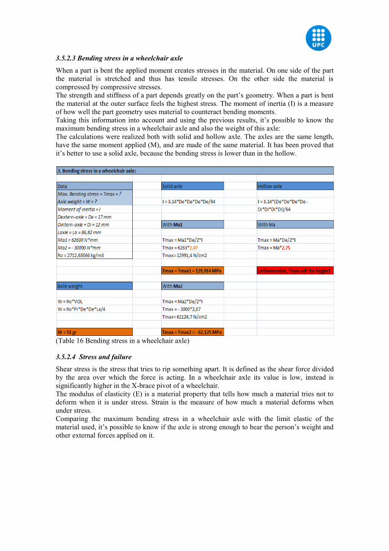
3.5.2.3 Bending stress in a wheelchair axle
When a part is bent the applied moment creates stresses in the material. On one side of the part the material is stretched and thus has tensile stresses. On the other side the material is compressed by compressive stresses.The strength and stiffness of a part depends greatly on the part’s geometry. When a part is bent the material at the outer surface feels the highest stress. The moment of inertia (I) is a measure of how well the part geometry uses material to counteract bending moments.Taking this information into account and using the previous results, it’s possible to know the maximum bending stress in a wheelchair axle and also the weight of this axle: The calculations were realized both with solid and hollow axle. The axles are the same length, have the same moment applied (M), and are made of the same material. It has been proved that it’s better to use a solid axle, because the bending stress is lower than in the hollow.
(Table 16 Bending stress in a wheelchair axle)
3.5.2.4 Stress and failure
Shear stress is the stress that tries to rip something apart. It is defined as the shear force divided by the area over which the force is acting. In a wheelchair axle its value is low, instead is significantly higher in the X-brace pivot of a wheelchair.The modulus of elasticity (E) is a material property that tells how much a material tries not to deform when it is under stress. Strain is the measure of how much a material deforms when under stress.Comparing the maximum bending stress in a wheelchair axle with the limit elastic of the material used, it’s possible to know if the axle is strong enough to bear the person’s weight and other external forces applied on it.
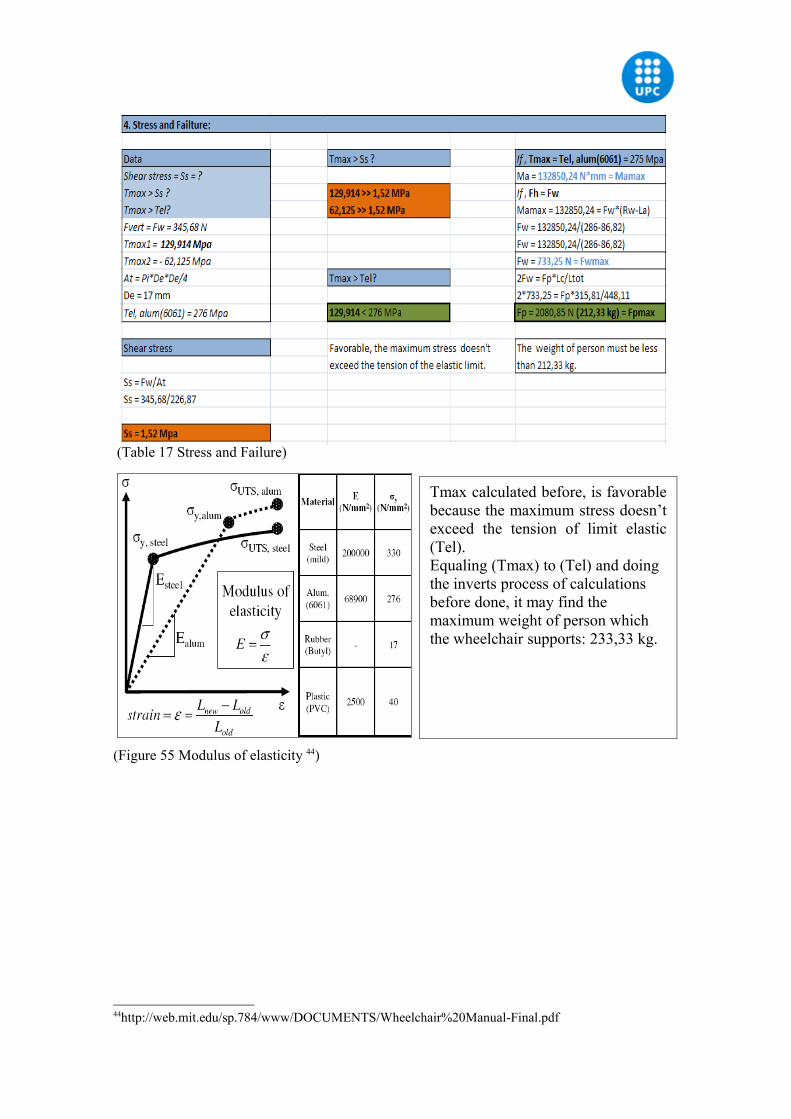
(Table 17 Stress and Failure)
(Figure 55 Modulus of elasticity 44)
44http://web.mit.edu/sp.784/www/DOCUMENTS/Wheelchair%20Manual-Final.pdf
Tmax calculated before, is favorable because the maximum stress doesn’t exceed the tension of limit elastic (Tel). Equaling (Tmax) to (Tel) and doing the inverts process of calculations before done, it may find the maximum weight of person which the wheelchair supports: 233,33 kg.
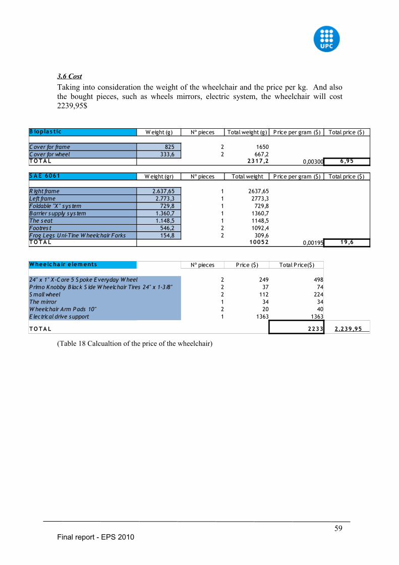
3.6 CostTaking into consideration the weight of the wheelchair and the price per kg. And also the bought pieces, such as wheels mirrors, electric system, the wheelchair will cost 2239,95$
(Table 18 Calcualtion of the price of the wheelchair)
59Final report - EPS 2010
B iopla s tic W eight (g) Nº pieces Total weight (g) P rice per gram ($) Total price ($)
C over for frame 825 2 1650C over for wheel 333,6 2 667,2T O T A L 2317,2 0,00300 6,95
S A E 6061 W eight (gr) Nº pieces Total weight P rice per gram ($) Total price ($)
R ight frame 2.637,65 1 2637,65Left frame 2.773,3 1 2773,3Foldable "X " s ys tem 729,8 1 729,8Barrier s upply s ys tem 1.360,7 1 1360,7The s eat 1.148,5 1 1148,5Footres t 546,2 2 1092,4Frog Legs Uni-Tine W heelchair Forks 154,8 2 309,6T O T A L 10052 0,00195 19,6
W heelc ha ir e lem ents Nº pieces P rice ($) Total Price($)
24" x 1" X -C ore 5 S poke E veryday W heel 2 249 498P rimo Knobby B lack S ide W heelchair Tires 24" x 1-3/8" 2 37 74S mall wheel 2 112 224The mirror 1 34 34W heelchair Arm Pads 10" 2 20 40E lectrical drive s upport 1 1363 1363
T O T A L 2233 2.239,95
4. Conclusion
As a final result of intensive efforts the design of the completely new wheelchair was achieved. The wheelchair can pass over most barriers that can be found in the urban environment. This is possible because the wheelchair is equipped with a barrier supplier system developed by our team which helps to pass over steps and curbstones. It brings a breath of a fresh air on the wheelchairs market. There is no such system at the moment on the market, so this leads to a strong competitive advantage. Similarly, the concept of covers with changeable design stickers, which may be adjusted according to the user preferences, is something unprecedented. This innovation makes it possible for the user to change the wheelchairs appearance, customizing it to every specific user. Another feature that distinguishes this wheelchair design from others is that the wheelchair frame is foldable; and at the same time it has also an electric system that helps to propel when it is necessary. If there is no requirement, the engine may be turned off or even just not bought. The implementation of this design will result in financial success of the producer and high increase of independence of disabled people. With all these characteristics the outcome is an improvement of the quality of life which was the main aim of the multidisciplinary team. The price of the wheelchair will not be exaggerated so almost everyone who would like to purchase it will be able to do that. It brings a new quality on the wheelchair market and will made disabled people more mobile than ever.
60Final report - EPS 2010
5. Bibliography
1. http://www.nabd.org.uk/adaptions/wheelchair.htm2. http://www.ibotnow.com/home.html3. http://www.ncbi.nlm.nih.gov/pubmed/68425674. http://www.1800wheelchair.com/asp/view-product.asp?product_id=10835. http://www.spinlife.com/category.cfm?categoryID=86. http://www.thewheelchairsite.com/all-terrain-wheelchairs.aspx7. http://transportwheelchair.org/8. http://en.wikipedia.org/wiki/Wheelchair.com9. http://www.1800wheelchair.com10. http://www.ncbi.nlm.nih.gov/pubmed/684256711. http://www.thewheelchairsite.com/shower-wheelchairs.aspx12. http://www.thewheelchairsite.com/all-terrain-wheelchairs.aspx13. http://www.allegromedical.com 14. www.evd.nl15. http://www.nakedcapitalism.com/2009/07/spain-bleak-forecast-puts-
unemployment.html16. http://www.marketingonline.nl/nieuws/bericht/just-do-it-yourself17. www.evd.nl18. http://www.europa-nu.nl/id/vifag4z8bmzj/nieuws/de_eu_streeft_naar_snelle_ratificatie?
ctx=vhsjhdfktnpb19. http://nullbarriere.de/rollstuhl.htm?layout=nullbarriere20. http://www.iloveebikes.com/batteries.html21. http://www.electric-bikes.com/betterbikes/bmc.html22. http://en.wikipedia.org/wiki/Brushless_DC_electric_motor23. http://dev.emcelettronica.com/files/u4/Brushless_DC_Motors_bldc_motor.jpghttp://24. www.electric-bikes.com/betterbikes/bmc.html25. W. Cubberly, Tool and Manufacturing Engineers Handbook, Society of Manufacturing
Engineers; Desk edition , 1989, ISBN 0 8726 3351 926. Michael F.Ashby, Materials Selection in Mechanical Design, Pergamon Press , 2005
ISBN 0-7506-6168-227. http://en.wikipedia.org/wiki/Aluminium_alloy28. www.azom.com29. http://tecnaro.de30. http://en.wikipedia.org/wiki/Acrylonitrile_butadiene_styrene31. Walter Fung , Coated and Laminated Textiles , Boca Raton ,2002, ISBN 0-8493-1448-732. http://web.mit.edu/sp.784/www/DOCUMENTS/Wheelchair%20Manual-Final.pdf
61Final report - EPS 2010
6. Appendix
Appendix 1 Groups and associationsThe list of R&D groups and associations related to the topics. This is useful for information.
• The Rehabilitation Engineering and Assistive Technology Society of North America• Department of Rehabilitation Science and Technology University of Pittsburgh• National Institute on Disability and Rehabilitation Research• Human Engineering Research Laboratories VA Pittsburgh
(http://www.herlpitt.org/home.html)• Center for International Rehabilitation Research Information and Exchange• The National Center for Dissemination of Disability Research• Disability Data - an InfoUse Project
(http://www.infouse.com/disabilitydata/home/index.php)• The National Rehabilitation Information Center• ABLEDATA - an Information Source for Assistive Technology
(http://www.abledata.com/).• Instituto Municipal de la Discapacidad• Asociación cívica de ayuda mutua• Asociación minusválidos de la autonomía catalana• Federación catalana del deporte de personas con discapacidad física• Fundación Integración• ASPAYM• ECOM• Associació Disminuïts de Sants-Montjuïc• Fundació Albà• Club Esportiu ASPACE Barcelona• Vocalia de Persones amb Discapacitat de l'Associació de Veïns de Sant Martí de
Provençals
62Final report - EPS 2010
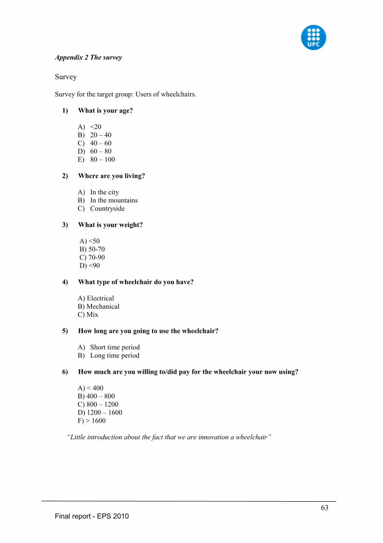
Appendix 2 The survey
Survey
Survey for the target group: Users of wheelchairs.
1) What is your age?
A) <20B) 20 – 40C) 40 – 60D) 60 – 80 E) 80 – 100
2) Where are you living?
A) In the cityB) In the mountainsC) Countryside
3) What is your weight?
A) <50 B) 50-70 C) 70-90 D) <90
4) What type of wheelchair do you have?
A) Electrical B) Mechanical C) Mix
5) How long are you going to use the wheelchair?
A) Short time periodB) Long time period
6) How much are you willing to/did pay for the wheelchair your now using?
A) < 400 B) 400 – 800C) 800 – 1200 D) 1200 – 1600 F) > 1600
“Little introduction about the fact that we are innovation a wheelchair”
63Final report - EPS 2010
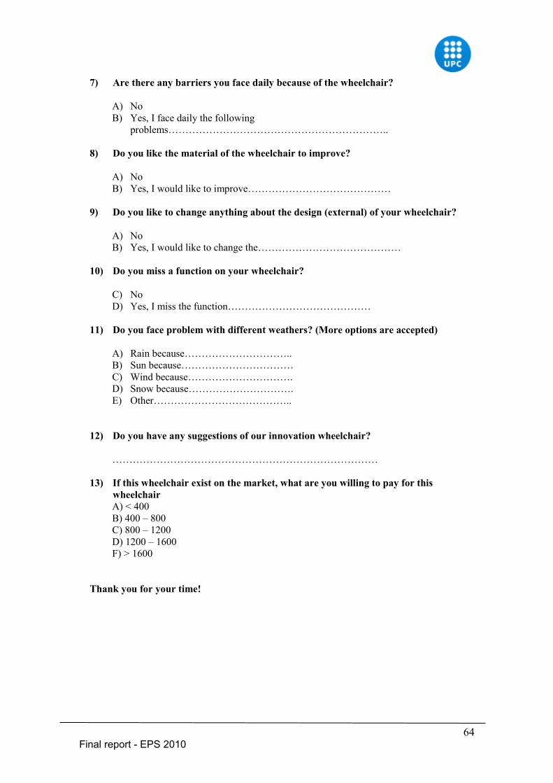
7) Are there any barriers you face daily because of the wheelchair?
A) NoB) Yes, I face daily the following
problems………………………………………………………..
8) Do you like the material of the wheelchair to improve?
A) NoB) Yes, I would like to improve……………………………………
9) Do you like to change anything about the design (external) of your wheelchair?
A) No B) Yes, I would like to change the……………………………………
10) Do you miss a function on your wheelchair?
C) NoD) Yes, I miss the function……………………………………
11) Do you face problem with different weathers? (More options are accepted)
A) Rain because…………………………..B) Sun because……………………………C) Wind because………………………….D) Snow because………………………….E) Other…………………………………..
12) Do you have any suggestions of our innovation wheelchair?
……………………………………………………………………
13) If this wheelchair exist on the market, what are you willing to pay for this wheelchairA) < 400 B) 400 – 800C) 800 – 1200 D) 1200 – 1600 F) > 1600
Thank you for your time!
64Final report - EPS 2010
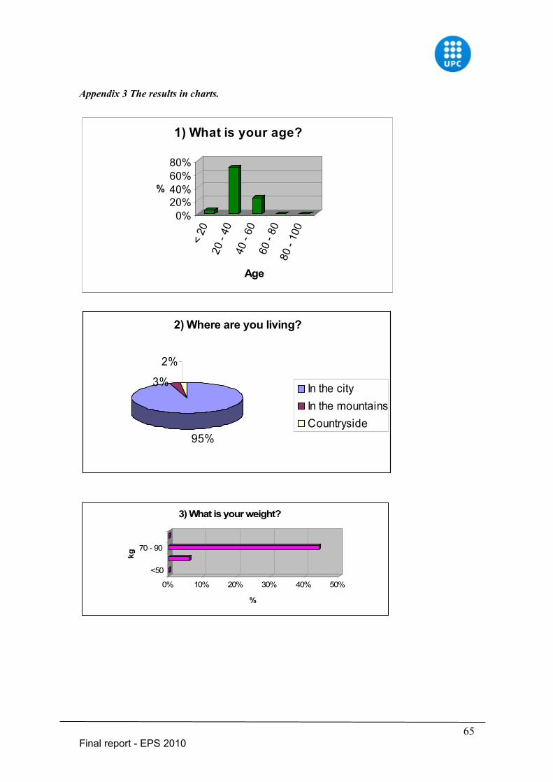
Appendix 3 The results in charts.
0%20%40%60%80%
%<
2020
- 40
40 -
6060
- 80
80 -
100
Age
1) What is your age?
2) Where are you living?
95%
3%
2%
In the cityIn the mountainsCountryside
0% 10% 20% 30% 40% 50%
%
<50
70 - 90
kg
3) What is your weight?
65Final report - EPS 2010
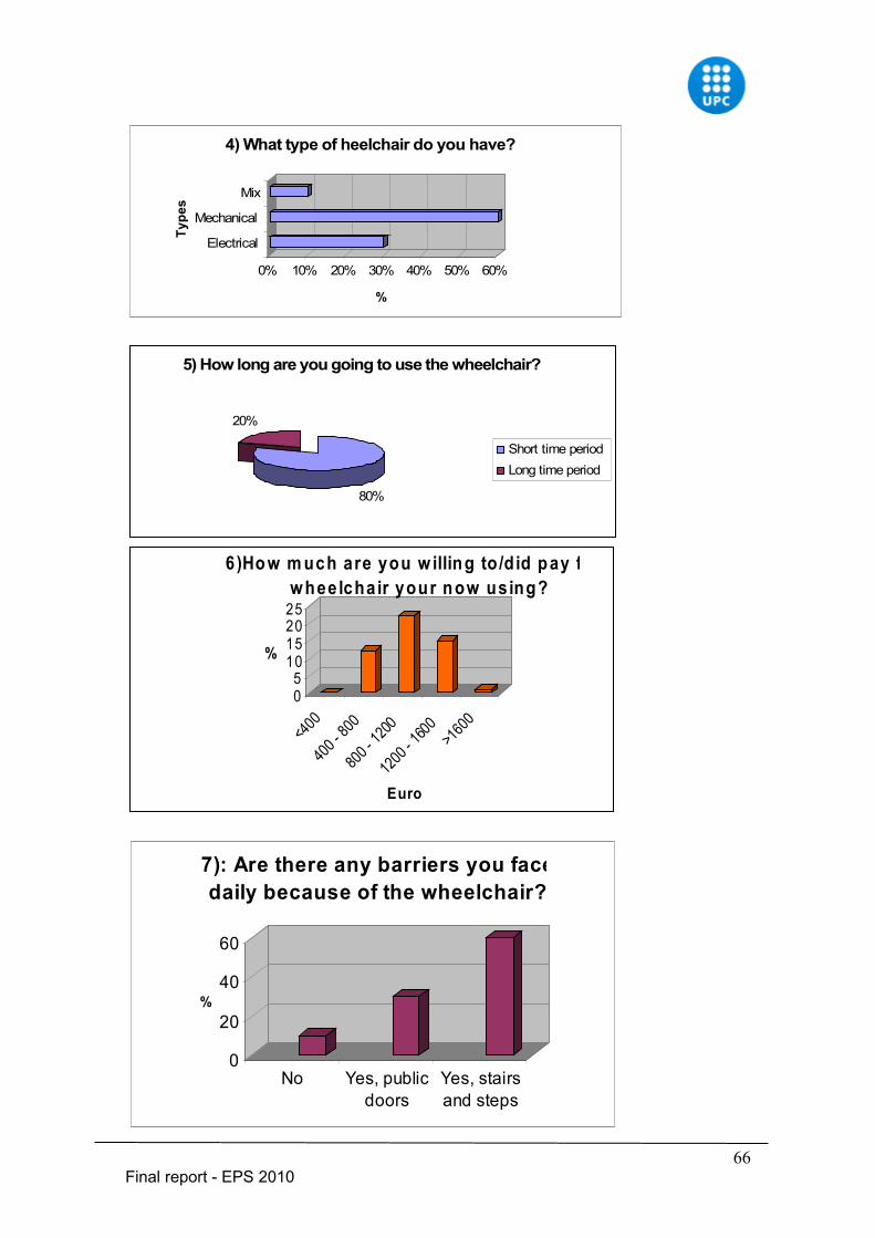
0% 10% 20% 30% 40% 50% 60%
%
Electrical
Mechanical
MixTy
pes
4) What type of heelchair do you have?
5) How long are you going to use the wheelchair?
80%
20%
Short time periodLong time period
05
10152025
%
<400
400 -
800
800 -
1200
1200
- 1600 >1
600
Euro
6)How m uch are you w illing to /d id pay fo r the w hee lcha ir your now using?
0
20
40
60
%
No Yes, publicdoors
Yes, stairsand steps
7): Are there any barriers you face daily because of the wheelchair?
66Final report - EPS 2010
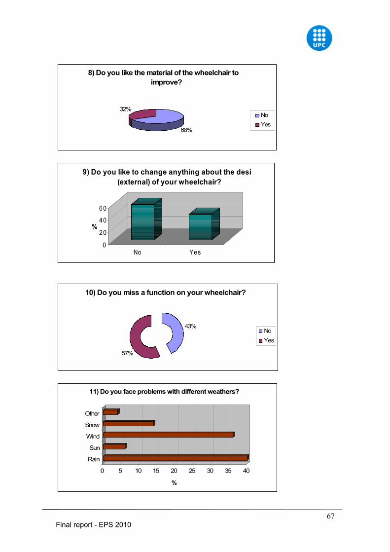
8) Do you like the material of the wheelchair to improve?
68%
32%NoYes
0
20
40
60
%
No Yes
9) Do you like to change anything about the design (external) of your wheelchair?
10) Do you miss a function on your wheelchair?
57%
43%NoYes
0 5 10 15 20 25 30 35 40
%
Rain
Sun
Wind
Snow
Other
11) Do you face problems with different weathers?
67Final report - EPS 2010
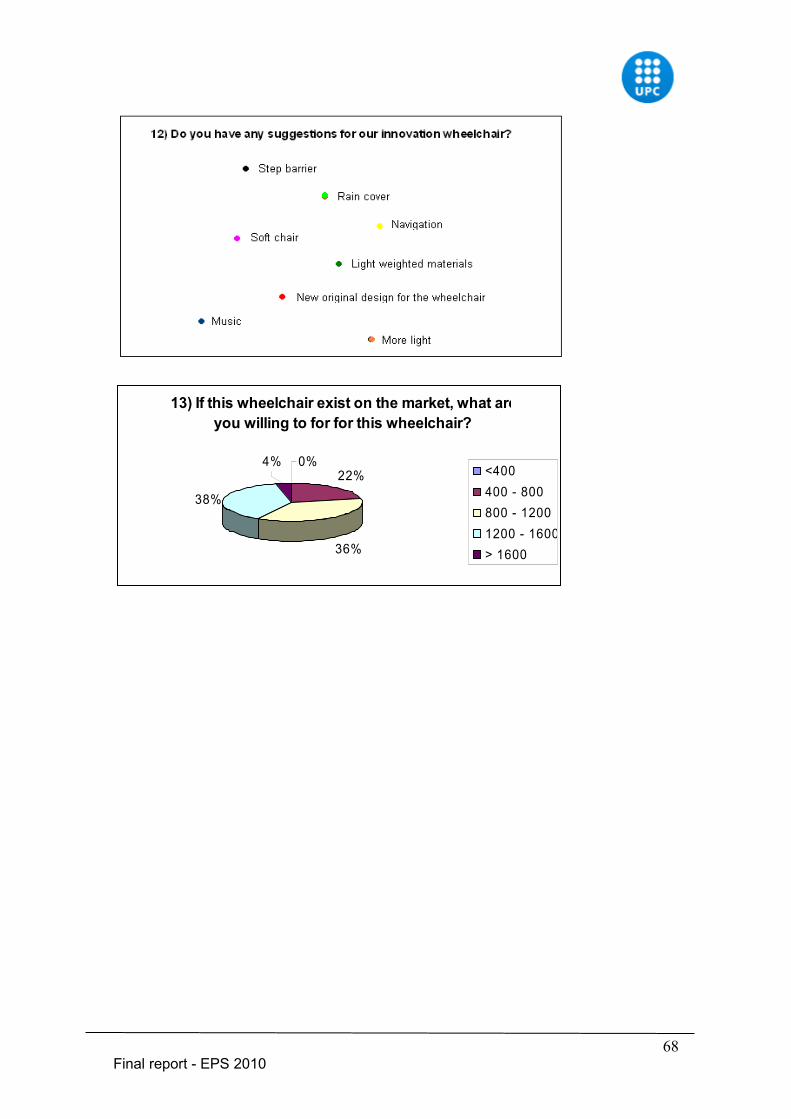
13) If this wheelchair exist on the market, what are you willing to for for this wheelchair?
22%
36%
38%
4% 0%<400400 - 800800 - 12001200 - 1600> 1600
68Final report - EPS 2010
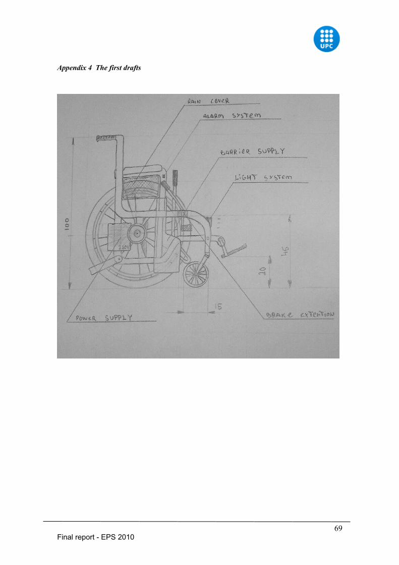
Appendix 4 The first drafts
69Final report - EPS 2010
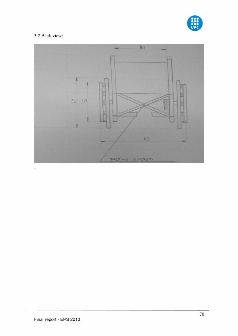
3.2 Back view:
70Final report - EPS 2010
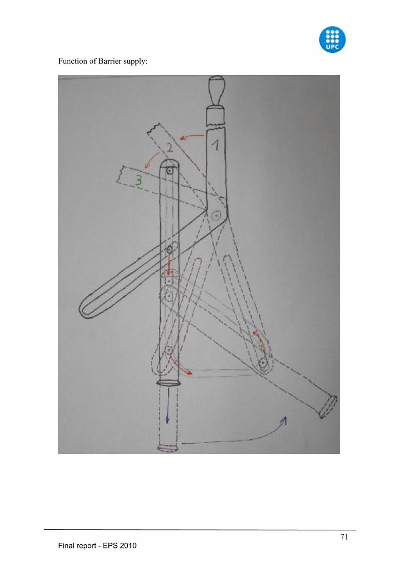
Function of Barrier supply:
71Final report - EPS 2010
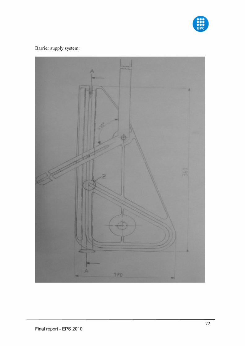
Barrier supply system:
72Final report - EPS 2010
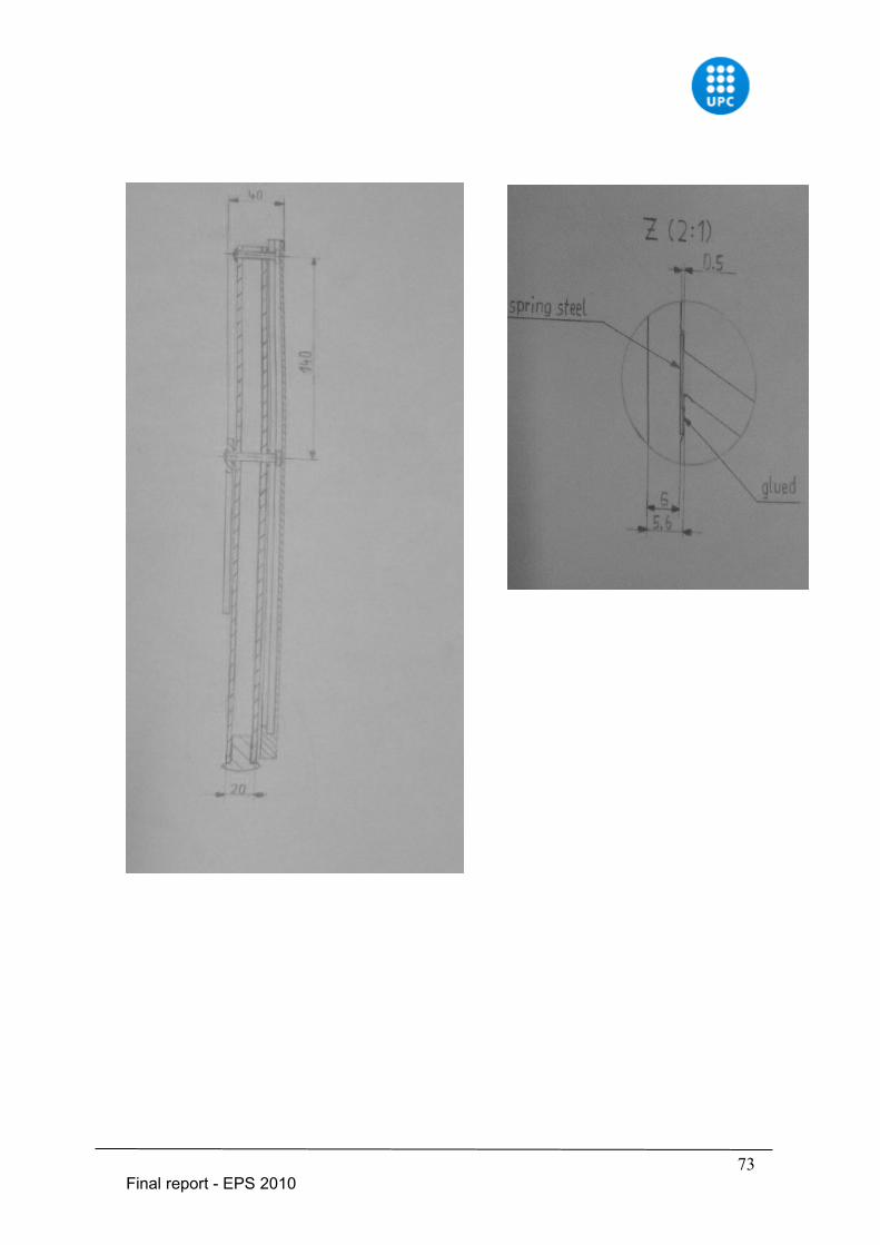
73Final report - EPS 2010
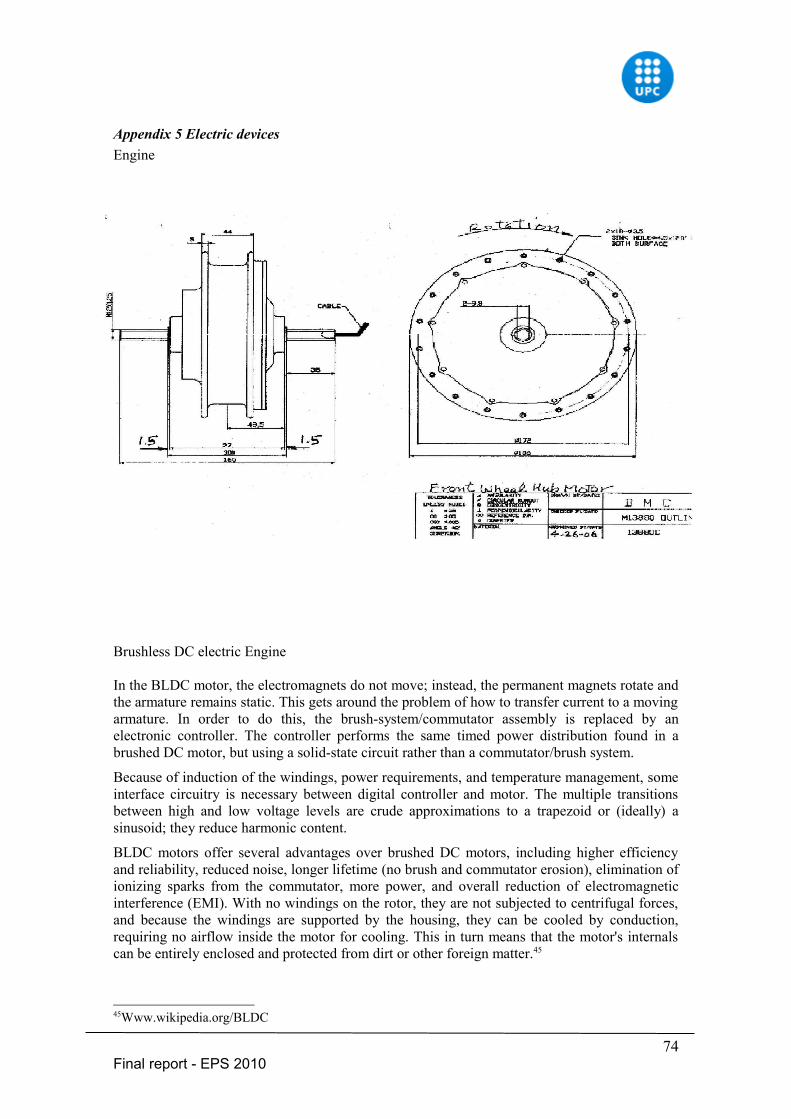
Appendix 5 Electric devicesEngine
Brushless DC electric Engine
In the BLDC motor, the electromagnets do not move; instead, the permanent magnets rotate and the armature remains static. This gets around the problem of how to transfer current to a moving armature. In order to do this, the brush-system/commutator assembly is replaced by an electronic controller. The controller performs the same timed power distribution found in a brushed DC motor, but using a solid-state circuit rather than a commutator/brush system.
Because of induction of the windings, power requirements, and temperature management, some interface circuitry is necessary between digital controller and motor. The multiple transitions between high and low voltage levels are crude approximations to a trapezoid or (ideally) a sinusoid; they reduce harmonic content.
BLDC motors offer several advantages over brushed DC motors, including higher efficiency and reliability, reduced noise, longer lifetime (no brush and commutator erosion), elimination of ionizing sparks from the commutator, more power, and overall reduction of electromagnetic interference (EMI). With no windings on the rotor, they are not subjected to centrifugal forces, and because the windings are supported by the housing, they can be cooled by conduction, requiring no airflow inside the motor for cooling. This in turn means that the motor's internals can be entirely enclosed and protected from dirt or other foreign matter.45
45Www.wikipedia.org/BLDC
74Final report - EPS 2010
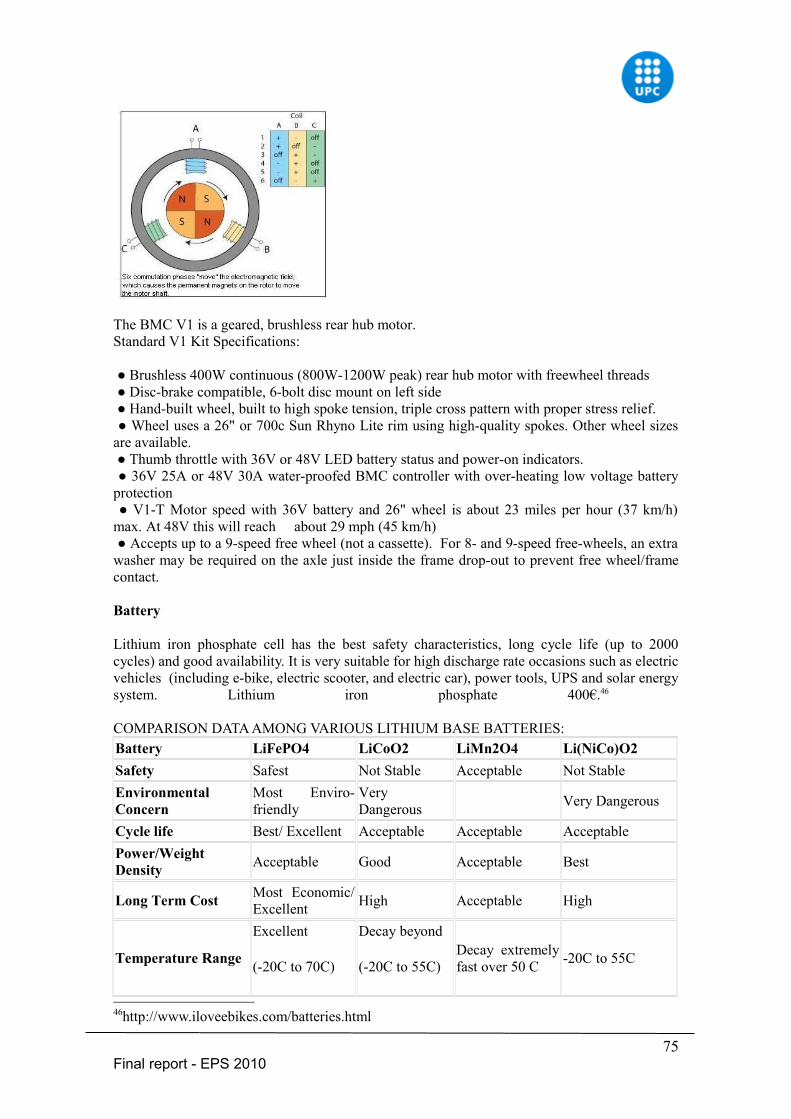
The BMC V1 is a geared, brushless rear hub motor.Standard V1 Kit Specifications:
● Brushless 400W continuous (800W-1200W peak) rear hub motor with freewheel threads ● Disc-brake compatible, 6-bolt disc mount on left side ● Hand-built wheel, built to high spoke tension, triple cross pattern with proper stress relief. ● Wheel uses a 26" or 700c Sun Rhyno Lite rim using high-quality spokes. Other wheel sizes are available. ● Thumb throttle with 36V or 48V LED battery status and power-on indicators. ● 36V 25A or 48V 30A water-proofed BMC controller with over-heating low voltage battery protection ● V1-T Motor speed with 36V battery and 26" wheel is about 23 miles per hour (37 km/h) max. At 48V this will reach about 29 mph (45 km/h) ● Accepts up to a 9-speed free wheel (not a cassette). For 8- and 9-speed free-wheels, an extra washer may be required on the axle just inside the frame drop-out to prevent free wheel/frame contact.
Battery
Lithium iron phosphate cell has the best safety characteristics, long cycle life (up to 2000 cycles) and good availability. It is very suitable for high discharge rate occasions such as electric vehicles (including e-bike, electric scooter, and electric car), power tools, UPS and solar energy system. Lithium iron phosphate 400€.46
COMPARISON DATA AMONG VARIOUS LITHIUM BASE BATTERIES:Battery LiFePO4 LiCoO2 LiMn2O4 Li(NiCo)O2Safety Safest Not Stable Acceptable Not StableEnvironmental Concern
Most Enviro-friendly
Very Dangerous Very Dangerous
Cycle life Best/ Excellent Acceptable Acceptable AcceptablePower/Weight Density Acceptable Good Acceptable Best
Long Term Cost Most Economic/ Excellent High Acceptable High
Temperature Range
Excellent
(-20C to 70C)
Decay beyond
(-20C to 55C)Decay extremely fast over 50 C -20C to 55C
46http://www.iloveebikes.com/batteries.html
75Final report - EPS 2010
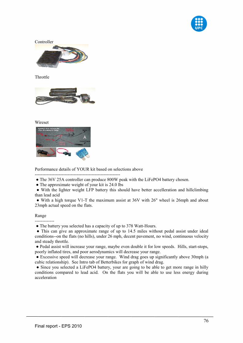
Controller
Throttle
Wireset
Performance details of YOUR kit based on selections above--------------------------------------------------------- ● The 36V 25A controller can produce 800W peak with the LiFePO4 battery chosen. ● The approximate weight of your kit is 24.0 lbs ● With the lighter weight LFP battery this should have better accelleration and hillclimbing than lead acid ● With a high torque V1-T the maximum assist at 36V with 26" wheel is 26mph and about 23mph actual speed on the flats.
Range------------- ● The battery you selected has a capacity of up to 378 Watt-Hours. ● This can give an approximate range of up to 14.5 miles without pedal assist under ideal conditions--on the flats (no hills), under 26 mph, decent pavement, no wind, continuous velocity and steady throttle. ● Pedal assist will increase your range, maybe even double it for low speeds. Hills, start-stops, poorly inflated tires, and poor aerodynamics will decrease your range. ● Excessive speed will decrease your range. Wind drag goes up significantly above 30mph (a cubic relationship). See Intro tab of Betterbikes for graph of wind drag. ● Since you selected a LiFePO4 battery, your are going to be able to get more range in hilly conditions compared to lead acid. On the flats you will be able to use less energy during acceleration
76Final report - EPS 2010
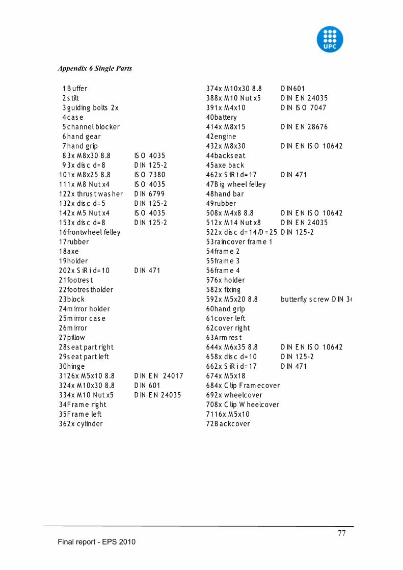
Appendix 6 Single Parts
77Final report - EPS 2010
1 B uffer 374x M 10x30 8.8 D IN 6012 s tilt 388x M 10 N ut x5 D IN E N 240353 guiding bolts 2x 391x M 4x10 D IN IS O 70474 cas e 40battery5 channel bloc ker 414x M 8x15 D IN E N 286766 hand gear 42eng ine7 hand g rip 432x M 8x30 D IN E N IS O 106428 3x M 8x30 8.8 IS O 4035 44backs eat9 3x dis c d= 8 D IN 125-2 45axe back
101x M 8x25 8.8 IS O 7380 462x S iR i d= 17 D IN 471111x M 8 N ut x4 IS O 4035 47B ig wheel felley122x thrus t was her D IN 6799 48hand bar132x dis c d= 5 D IN 125-2 49rubber142x M 5 N ut x4 IS O 4035 508x M 4x8 8.8 D IN E N IS O 10642153x dis c d= 8 D IN 125-2 512x M 14 N ut x8 D IN E N 2403516frontw heel felley 522x dis c d= 14/D = 25 D IN 125-217rubber 53ra incover fram e 118axe 54fram e 219holder 55fram e 3202x S iR i d= 10 D IN 471 56fram e 421footres t 576x holder22footres tholder 582x fixing23block 592x M 5x20 8.8 butterfly s c rew D IN 36124m irror holder 60hand g rip25m irror c as e 61cover left26m irror 62cover right27pillow 63Arm res t28s eat part right 644x M 6x35 8.8 D IN E N IS O 1064229s eat part left 658x dis c d= 10 D IN 125-230hinge 662x S iR i d= 17 D IN 4713126x M 5x10 8.8 D IN E N 24017 674x M 5x18324x M 10x30 8.8 D IN 601 684x C lip F ram ecover334x M 10 N ut x5 D IN E N 24035 692x wheelcover34F ram e right 708x C lip W heelcover35F ram e left 7116x M 5x10362x cylinder 72B ackcover