Embed Size (px)
Citation preview

Epsilon User Manual
Managed 8-Port Gigabit Ethernet Switch
Revision Date Comment
A.1 01/8/2013 Minor Update
Copyright 2014 FOR TECHNICAL SUPPORT Diamond Systems Corporation PLEASE CONTACT: 555 Ellis Street Mountain View, CA 94043 USA [email protected] Tel 1-650-810-2500 Fax 1-650-810-2525 www.diamondsystems.com

Epsilon User Manual Revision A.1 www.diamondsystems.com Page 2
CONTENTS
1. Important Safe Handling Information .............................................................................................................3 2. Introduction .......................................................................................................................................................4
2.1 Features .........................................................................................................................................................4 2.2 Main Feature List ...........................................................................................................................................4 2.3 Mechanical and Environmental .....................................................................................................................5 2.4 Cable List .......................................................................................................................................................5
3. Functional Overview .........................................................................................................................................6 3.1 Functional Block Diagram ..............................................................................................................................6
4. Board Outline and Layout ................................................................................................................................7 4.1 Epsilon Board Drawing ..................................................................................................................................7
5. Connector and Jumper List .............................................................................................................................8 5.1 Connector List ................................................................................................................................................8 5.2 Jumper Block (J15) ........................................................................................................................................8
6. Connector Pinout and Pin Description ...........................................................................................................9 6.1 PC/104 Connectors (J1 and J2) - Optional ...................................................................................................9 6.2 PCI Power (J3) - Optional ........................................................................................................................... 10 6.3 Ethernet (J4-J11) ........................................................................................................................................ 10 6.4 Serial Interface (J12) .................................................................................................................................. 10 6.5 JTAG (J16) – Factory Use Only ................................................................................................................. 10 6.6 LED Status Signals (J13) ........................................................................................................................... 11 6.7 Input Power (J14) ....................................................................................................................................... 11
7. Command Line Interface ............................................................................................................................... 12 7.1 Com Port Set-up ......................................................................................................................................... 12 7.2 Command Hierarchy ................................................................................................................................... 12 7.3 Login/Logout Procedures ........................................................................................................................... 12 7.4 Help Utility ................................................................................................................................................... 13 7.5 Example ...................................................................................................................................................... 13 7.6 Entering Commands ................................................................................................................................... 14 7.7 Terminology ................................................................................................................................................ 14 7.8 Changing the IP Address ............................................................................................................................ 15 7.9 Command Overview ................................................................................................................................... 15 7.10 Detailed Command Description .................................................................................................................. 17
7.10.1 System Commands ............................................................................................................................ 18 7.10.2 Console Commands .......................................................................................................................... 19 7.10.3 Port Commands ................................................................................................................................. 19 7.10.4 MAC Table Commands ...................................................................................................................... 20 7.10.5 VLAN Commands .............................................................................................................................. 21 7.10.6 Aggregation/Trunking Commands ..................................................................................................... 22 7.10.7 LACP Commands .............................................................................................................................. 23 7.10.8 RSTP Commands .............................................................................................................................. 23 7.10.9 User Group Commands ..................................................................................................................... 25 7.10.10 QoS Commands ................................................................................................................................ 25 7.10.11 Mirror Commands .............................................................................................................................. 26 7.10.12 IP Commands .................................................................................................................................... 27 7.10.13 Dot1X Commands .............................................................................................................................. 28 7.10.14 IGMP Snooping Commands .............................................................................................................. 29 7.10.15 Debug Commands ............................................................................................................................. 29
7.11 Examples .................................................................................................................................................... 30 7.11.1 VLAN configuration ............................................................................................................................ 30 7.11.2 User Group Configuration .................................................................................................................. 30
8. Web Interface ................................................................................................................................................. 31 9. Thermal Solutions.......................................................................................................................................... 32
9.1 Heatspreader .............................................................................................................................................. 32 9.2 Heatsink ...................................................................................................................................................... 33
10. Specifications ................................................................................................................................................. 34 Appendix A Default values .............................................................................................................................. 35

Epsilon User Manual Revision A www.diamondsystems.com Page 3
1. IMPORTANT SAFE HANDLING INFORMATION
WARNING!
ESD-Sensitive Electronic Equipment
Observe ESD-safe handling procedures when working with this product.
Always use this product in a properly grounded work area and wear appropriate ESD-preventive clothing and/or accessories.
Always store this product in ESD-protective packaging when not in use.
Safe Handling Precautions
The Epsilon board contains a high density connector with many connections to sensitive electronic components. This creates many opportunities for accidental damage during handling, installation and connection to other equipment. The list here describes common causes of failure found on boards returned to Diamond Systems for repair. This information is provided as a source of advice to help you prevent damaging your Diamond (or any vendor’s) boards.
ESD damage – This type of damage is usually almost impossible to detect, because there is no visual sign of failure or damage. The symptom is that the board eventually simply stops working, because some component becomes defective. Usually the failure can be identified and the chip can be replaced. To prevent ESD damage, always follow proper ESD-prevention practices when handling computer boards.
Damage during handling or storage – On some boards we have noticed physical damage from mishandling. A common observation is that a screwdriver slipped while installing the board, causing a gouge in the PCB surface and cutting signal traces or damaging components.
Another common observation is damaged board corners, indicating the board was dropped. This may or may not cause damage to the circuitry, depending on what is near the corner. Most of our boards are designed with at least 25 mils clearance between the board edge and any component pad, and ground / power planes are at least 20 mils from the edge to avoid possible shorting from this type of damage. However these design rules are not sufficient to prevent damage in all situations.
A third cause of failure is when a metal screwdriver tip slips, or a screw drops onto the board while it is powered on, causing a short between a power pin and a signal pin on a component. This can cause overvoltage / power supply problems described below. To avoid this type of failure, only perform assembly operations when the system is powered off.
Sometimes boards are stored in racks with slots that grip the edge of the board. This is a common practice for board manufacturers. However our boards are generally very dense, and if the board has components very close to the board edge, they can be damaged or even knocked off the board when the board tilts back in the rack. Diamond recommends that all our boards be stored only in individual ESD-safe packaging. If multiple boards are stored together, they should be contained in bins with dividers between boards. Do not pile boards on top of each other or cram too many boards into a small location. This can cause damage to connector pins or fragile components.
Power supply wired backwards – Our power supplies and boards are not designed to withstand a reverse power supply connection. This will destroy each IC that is connected to the power supply (i.e. almost all ICs). In this case the board will most likely will be unrepairable and must be replaced. A chip destroyed by reverse power or by excessive power will often have a visible hole on the top or show some deformation on the top surface due to vaporization inside the package. Check twice before applying power!
Overvoltage on analog input – If a voltage applied to an analog input exceeds the design specification of the board, the input multiplexor and/or parts behind it can be damaged. Most of our boards will withstand an
erroneous connection of up to 35V on the analog inputs, even when the board is powered off, but not all boards, and not in all conditions.
Overvoltage on analog output – If an analog output is accidentally connected to another output signal or a power supply voltage, the output can be damaged. On most of our boards, a short circuit to ground on an analog output will not cause trouble.
Overvoltage on digital I/O line – If a digital I/O signal is connected to a voltage above the maximum specified voltage, the digital circuitry can be damaged. On most of our boards the acceptable range of voltages connected to digital I/O signals is 0-5V, and they can withstand about 0.5V beyond that (-0.5 to 5.5V) before being damaged. However logic signals at 12V and even 24V are common, and if one of these is connected to a 5V logic chip, the chip will be damaged, and the damage could even extend past that chip to others in the circuit.

Epsilon User Manual Revision A.1 www.diamondsystems.com Page 4
2. INTRODUCTION
Epsilon is a managed, 8-Port Gigabit Ethernet Switch with wide power supply voltage input and a serial management port. Epsilon offers 10/100/1000Mbps copper twisted pair ports on a PC/104 format board. The circuit is standalone, so no bus connectors are required. Optional PC/104 bus connectors are available to facilitate the installation in the interior of a stack of boards. An RS-232 interface is provided to enable communication between the on-board management microcontroller and a host processor through a Command Line Interface (CLI). A wide-range DC power supply is built into the board to allow it to be used with industrial power sources as well as the typical embedded +5V supply.
Highly Advanced Gigabit Ethernet Switch
Epsilon is an 8-port Gigabit Ethernet switch in the compact PC/104 form factor. Epsilon operates standalone, but
can be included in any PC/104 board stack.
Layer 2+ Managed Switch
Epsilon’s Ethernet switch chip includes a built-in microcontroller for configuration and management. It can be
accessed either through the on-board RS-232 port or one of the Ethernet ports.
Wide Power DC/DC Power Supply
Epsilon can be powered through a wide voltage +7-36V DC/DC power supply input or a regulated +5VDC input,
but not both at the same time. +5VDC power may also be provided through the PC/104 connector.
Rugged Design Extended temperature operation of -40°C to +85°C is tested and guaranteed. Epsilon was designed with harsh applications in mind. Latching connectors provide increased reliability.
PC/104 Bus Interface Optionally Epsilon provides a full passthrough PC/104 interface, allowing it to be integrated into any PC/104 stack.
Software Support The switch is ready to plug into your application without any driver installation or firmware upgrades. A web interface and a CLI provide an intuitive GUI for configuring and managing the switch.
2.1 Features
2.2 Main Feature List
PC/104 form factor
8 ports of 10/100/1000Mbps Ethernet over copper
Layer 2+ managed switch
Built-in microcontroller with management software and web interface for control and configuration
176KB on-board frame buffer; jumbo frame support at all speeds
8K MAC addresses and 4K VLANs (IEEE 802.1Q), 8K IP multicast group support
Programmable multi-layer classifier with 4 QoS classes
DSCP remarking for IPv4 and IPv6 frames
Rapid spanning tree protocol (RSTP)
Right angled, locking pin headers for all Ethernet ports (standard configuration)
Safe Flash/configuration update through web and serial interfaces
Reset signal available on Status Signal connector
Either +7-36VDC or +5VDC power supply input, but not both at the same time

Epsilon User Manual Revision A www.diamondsystems.com Page 5
2.3 Mechanical and Environmental
PC/104 compliant form factor including:
Board dimensions
Mounting holes
Component and optional heatsink height
Optional ISA bus connectors
-40°C to +85°C ambient operating temperature with heatspreader
or -40°C to +71°C ambient operating temperature with heatsink
2.4 Cable List
Part Number Cable Description
6981050 Serial cable
6981051 Power cable
6981052 Ethernet cable (1 per port)
PC/104™ and PC/104-Plus™ are trademarks of the PC/104 Embedded Consortium.
All other trademarks are the property of their respective owners.

Epsilon User Manual Revision A www.diamondsystems.com Page 6
3. FUNCTIONAL OVERVIEW
3.1 Functional Block Diagram
Figure 1. Functional Block Diagram
Epsilon is an 8-Port managed Gigabit Ethernet switch module offering 10/100/1000Mbps copper twisted pair ports on a PC/104 form factor board. Epsilon operates standalone, requiring no connection to a single board computer in the stack.
Epsilon is a Layer 2+ managed Ethernet switch with built-in microcontroller and memory for configuration and management. The Flash memory holds dual application images along with the boot code, The SRAM is used for program execution and storing the MAC addresses. The EEPROM holds the configuration parameters. .
An RS-232 interface is provided to enable communication between the on-board management microcontroller and a host processor through a CLI interface. The microcontroller is also accessible through one of the Ethernet ports via a web management interface.
Power can be provided through the +7-36VDC wide-range DC power supply built into the board, enabling use with industrial power sources. Epsilon can also be powered from a +5VDC input source, using either the main power connector or an optional connection to the PC/104 bus or PC/104-Plus (PCI) bus. The +7-36VDC wide-range DC power supply and +5VDC input source cannot be used simultaneously.

Epsilon User Manual Revision A www.diamondsystems.com Page 7
4. BOARD OUTLINE AND LAYOUT
4.1 Epsilon Board Drawing
The following diagram shows the locations for all connectors and jumpers which are described in the next sections.
Figure 2. Epsilon Top (Connectors and Jumpers)
Epsilon User Manual Revision A www.diamondsystems.com Page 8
5. CONNECTOR AND JUMPER LIST
5.1 Connector List
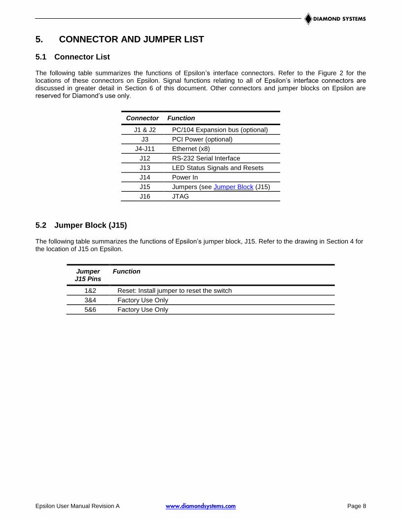
The following table summarizes the functions of Epsilon’s interface connectors. Refer to the Figure 2 for the locations of these connectors on Epsilon. Signal functions relating to all of Epsilon’s interface connectors are discussed in greater detail in Section 6 of this document. Other connectors and jumper blocks on Epsilon are reserved for Diamond’s use only.
Connector Function
J1 & J2 PC/104 Expansion bus (optional)
J3 PCI Power (optional)
J4-J11 Ethernet (x8)
J12 RS-232 Serial Interface
J13 LED Status Signals and Resets
J14 Power In
J15 Jumpers (see Jumper Block (J15)
J16 JTAG
5.2 Jumper Block (J15)
The following table summarizes the functions of Epsilon’s jumper block, J15. Refer to the drawing in Section 4 for the location of J15 on Epsilon.
Jumper J15 Pins
Function
1&2 Reset: Install jumper to reset the switch
3&4 Factory Use Only
5&6 Factory Use Only
Epsilon User Manual Revision A.1 www.diamondsystems.com Page 9
6. CONNECTOR PINOUT AND PIN DESCRIPTION
6.1 PC/104 Connectors (J1 and J2) - Optional
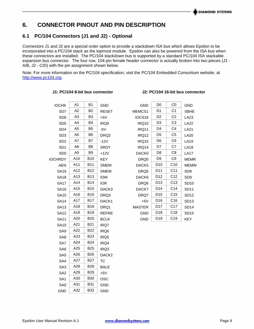
Connectors J1 and J2 are a special order option to provide a stackdown ISA bus which allows Epsilon to be incorporated into a PC/104 stack as the topmost module. Epsilon can also be powered from the ISA bus when these connectors are installed. The PC/104 stackdown bus is supported by a standard PC/104 ISA stackable expansion bus connector. The four row, 104-pin female header connector is actually broken into two pieces (J1 - A/B, J2 - C/D) with the pin assignment shown below.
Note: For more information on the PC/104 specification, visit the PC/104 Embedded Consortium website, at http://www.pc104.org.
J1: PC/104 8-bit bus connector J2: PC/104 16-bit bus connector
IOCHK A1 B1 GND GND D0 C0 GND
SD7 A2 B2 RESET MEMCS1
6
D1 C1 SBHE
SD6 A3 B3 +5V IOCS16 D2 C2 LA23
SD5 A4 B4 IRQ9 IRQ10 D3 C3 LA22
SD4 A5 B5 -5V IRQ11 D4 C4 LA21
SD3 A6 B6 DRQ2 IRQ12 D5 C5 LA20
SD2 A7 B7 -12V IRQ15 D6 C6 LA19
SD1 A8 B8 SRDY IRQ14 D7 C7 LA18
SD0 A9 B9 +12V DACK0 D8 C8 LA17
IOCHRDY A10 B10 KEY DRQ0 D9 C9 MEMR
AEN A11 B11 SMEM
W
DACK5 D10 C10 MEMW
SA19 A12 B12 SMEM
R
DRQ5 D11 C11 SD8
SA18 A13 B13 IOW DACK6 D12 C12 SD9
SA17 A14 B14 IOR DRQ6 D13 C13 SD10
SA16 A15 B15 DACK3 DACK7 D14 C14 SD11
SA15 A16 B16 DRQ3 DRQ7 D15 C15 SD12
SA14 A17 B17 DACK1 +5V D16 C16 SD13
SA13 A18 B18 DRQ1 MASTER D17 C17 SD14
SA12 A19 B19 REFRE
SH
GND D18 C18 SD15
SA11 A20 B20 BCLK GND D19 C19 KEY
SA10 A21 B21 IRQ7
SA9 A22 B22 IRQ6
SA8 A23 B23 IRQ5
SA7 A24 B24 IRQ4
SA6 A25 B25 IRQ3
SA5 A26 B26 DACK2
SA4 A27 B27 TC
SA3 A28 B28 BALE
SA2 A29 B29 +5V
SA1 A30 B30 OSC
SA0 A31 B31 GND
GND A32 B32 GND

Epsilon User Manual Revision A www.diamondsystems.com Page 10
6.2 PCI Power (J3) - Optional
Connector J3 is a special order option to supply power via the PCI bus. In the pinout below, the pins are noted as Epsilon pin number / PCI standard pin number. The function are also listed as Epsilon signal/PCI standard signal, with only one name when the function is common (i.e., +5V or ground).
NC / AD26 1 / B20 2 / A20 Ground
+5V 3 / B21 4 / A21 NC / AD269
NC / AD30 5 / B22 6 / A22 +5V
Ground 7 / B23 8 / A23 NC / REQ0#
NC / REQ2# 9 / B24 10 / A24 Ground
Connector Type: 2mm dual row straight pin header with gold flash plating
6.3 Ethernet (J4-J11)
Epsilon contains eight right-angle, locking pin headers for the eight Ethernet ports. Each port has the same style and pinout. Each signal is associated with a particular color inside of the Diamond Systems cable part number 6981052. The color coding for this cable follows the TIA/EIA 568B standard.
DD+ 1 2 DD-
DC+ 3 4 DC-
DB+ 5 6 DB-
DA+ 7 8 DA-
Ground 9 10 Ground
Connector Type: 2mm dual row right-angle, locking pin header with tin plating
Mating Connector: JST Sales America PUDP-10V-S housing with SPUD-002T-P0.5 terminals
6.4 Serial Interface (J12)
Epsilon contains an RS-232 connector, J12, that connects the on-board 8051 microcontroller to an external serial port.
1 Ground
2 TxD Out
3 RxD In
Connector Type: 2mm single row right-angle, locking pin header with tin plating
Mating Connector: Molex Connector 35507-0300 housing with 50212-8100 terminals
6.5 JTAG (J16) – Factory Use Only
This connector provides a scan capability that is for factory use only.
Epsilon User Manual Revision A www.diamondsystems.com Page 11
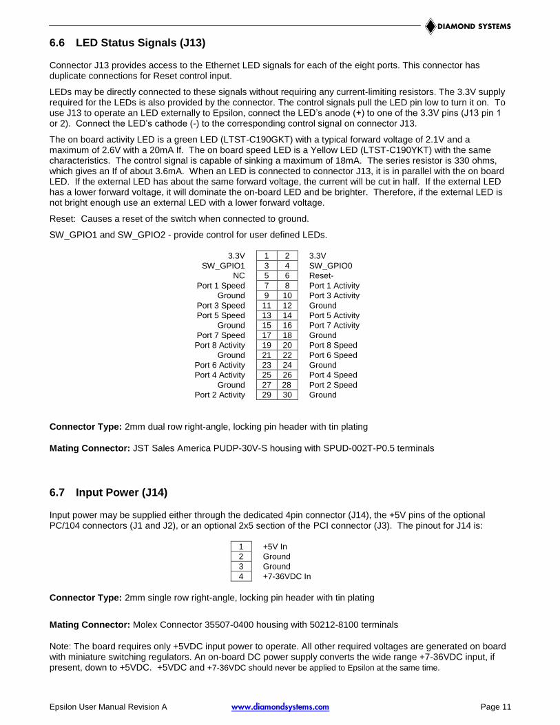
6.6 LED Status Signals (J13)
Connector J13 provides access to the Ethernet LED signals for each of the eight ports. This connector has duplicate connections for Reset control input.
LEDs may be directly connected to these signals without requiring any current-limiting resistors. The 3.3V supply required for the LEDs is also provided by the connector. The control signals pull the LED pin low to turn it on. To use J13 to operate an LED externally to Epsilon, connect the LED’s anode (+) to one of the 3.3V pins (J13 pin 1 or 2). Connect the LED’s cathode (-) to the corresponding control signal on connector J13.
The on board activity LED is a green LED (LTST-C190GKT) with a typical forward voltage of 2.1V and a maximum of 2.6V with a 20mA If. The on board speed LED is a Yellow LED (LTST-C190YKT) with the same characteristics. The control signal is capable of sinking a maximum of 18mA. The series resistor is 330 ohms, which gives an If of about 3.6mA. When an LED is connected to connector J13, it is in parallel with the on board LED. If the external LED has about the same forward voltage, the current will be cut in half. If the external LED has a lower forward voltage, it will dominate the on-board LED and be brighter. Therefore, if the external LED is not bright enough use an external LED with a lower forward voltage.
Reset: Causes a reset of the switch when connected to ground.
SW_GPIO1 and SW_GPIO2 - provide control for user defined LEDs.
3.3V 1 2 3.3V
SW_GPIO1 3 4 SW_GPIO0
NC 5 6 Reset-
Port 1 Speed 7 8 Port 1 Activity
Ground 9 10 Port 3 Activity
Port 3 Speed 11 12 Ground
Port 5 Speed 13 14 Port 5 Activity
Ground 15 16 Port 7 Activity
Port 7 Speed 17 18 Ground
Port 8 Activity 19 20 Port 8 Speed
Ground 21 22 Port 6 Speed
Port 6 Activity 23 24 Ground
Port 4 Activity 25 26 Port 4 Speed
Ground 27 28 Port 2 Speed
Port 2 Activity 29 30 Ground
Connector Type: 2mm dual row right-angle, locking pin header with tin plating
Mating Connector: JST Sales America PUDP-30V-S housing with SPUD-002T-P0.5 terminals
6.7 Input Power (J14)
Input power may be supplied either through the dedicated 4pin connector (J14), the +5V pins of the optional PC/104 connectors (J1 and J2), or an optional 2x5 section of the PCI connector (J3). The pinout for J14 is:
1 +5V In
2 Ground
3 Ground
4 +7-36VDC In
Connector Type: 2mm single row right-angle, locking pin header with tin plating
Mating Connector: Molex Connector 35507-0400 housing with 50212-8100 terminals
Note: The board requires only +5VDC input power to operate. All other required voltages are generated on board with miniature switching regulators. An on-board DC power supply converts the wide range +7-36VDC input, if present, down to +5VDC. +5VDC and +7-36VDC should never be applied to Epsilon at the same time.

Epsilon User Manual Revision A www.diamondsystems.com Page 12
7. COMMAND LINE INTERFACE
7.1 Com Port Set-up
To use the command line interface, you must connect the COM port of a PC to the RS-232 serial interface connector (J12) and activate a terminal program (e.g. HyperTerminal under Windows). The COM port must be set up to run 8 data bits, 1 stop bit, no parity, 38400 baud rate and without flow control.
7.2 Command Hierarchy
The CLI is hierarchical with two levels: a top level and a group level. The group level consists of the following groups:
• System
• Console
• Port
• MAC
• VLAN
• Aggregation
• LACP
• RSTP
• User Group
• QoS
• Mirror
• IP
• Dot1X
• IGMP
• Filter
• Debug
At the top level you may enter a command by giving the full command string, including group, or you may change context into a group by entering the name of the group.
At the group level you may enter commands for the particular group you have chosen without specifying the group name or you may return to the top level by entering the up command.
The current level and group is indicated by a user definable prompt. If you are at the top level, the default prompt will be:
>
If you are at group level, the prompt will display the actual group, e.g.
System>
At group level you also have the option of using the slash (/) key to refer to a context relative to the top level. E.g. you may be in the system group and enter a /console/configuration command or change context into the console group by entering /console.
7.3 Login/Logout Procedures
To get access to the CLI you must login by entering a password. You will automatically be queried about the password.
The password is configurable. The password check may be disabled by setting the password to an empty string “”, in which case any password entered during login will be accepted.
You may logout at any time and at any context level using the exit command.

Epsilon User Manual Revision A www.diamondsystems.com Page 13
7.4 Help Utility
You may get help by pressing the ? key or entering help. The help info depends on the context:
• At top level, a list of command groups is displayed.
• At group level, a list of the command syntaxes for the current group is displayed.
• If the help command is issued for a specific command, the command syntax and a description of the command are shown.
7.5 Example
The command hierarchy and the help utility is demonstrated in the following example:
> ? <enter>
Commands at top level:
System – System commands
Console – Console commands
Port – Port commands
MAC - MAC table commands
VLAN – VLAN commands
Aggregation – Aggregation/Trunking commands
LACP – IEEE802.3ad Link aggregation commands
RSTP – IEEE802.1w Rapid Spanning Tree commands
User Group – User Group commands
QoS – QoS commands
Mirror – Mirror commands
IP – IP commands
Dot1x – Dot1x commands
PoE - Power Over Ethernet commands
IGMP - IGMP Snooping commands
Filter - Filter commands
Debug - Debug commands
> console <enter>
Console> ? <enter>
Commands at Console level:
Console Configuration
Console Password [<password>]
Console Timeout [<timeout>]
Console Prompt [<prompt string>]
------
Up
Console> password ?
Syntax:
Console Password [<password>]
Description:
Epsilon User Manual Revision A www.diamondsystems.com Page 14
Set or display console password. The empty string (“”) disables the password
check.
[<password>]: Password string of up to 16 characters.
Console>
7.6 Entering Commands
• Commands are not case-sensitive.
• You may use the horizontal arrow-keys ← and → to move the cursor within the command you are entering.
• You may use the backspace key (provided you are using a terminal that sends the BS (8) character when the backspace key is pressed) to delete chars from the command you are entering.
• You may use the vertical arrow-keys ↑ and ↓ to scroll through a command history buffer of the latest 20 commands issued.
• If you are using a terminal (e.g. HyperTerminal) that supports <home> and <end> keys, you may use these keys to move the cursor to respectively the start of the command line and the end of the command line.
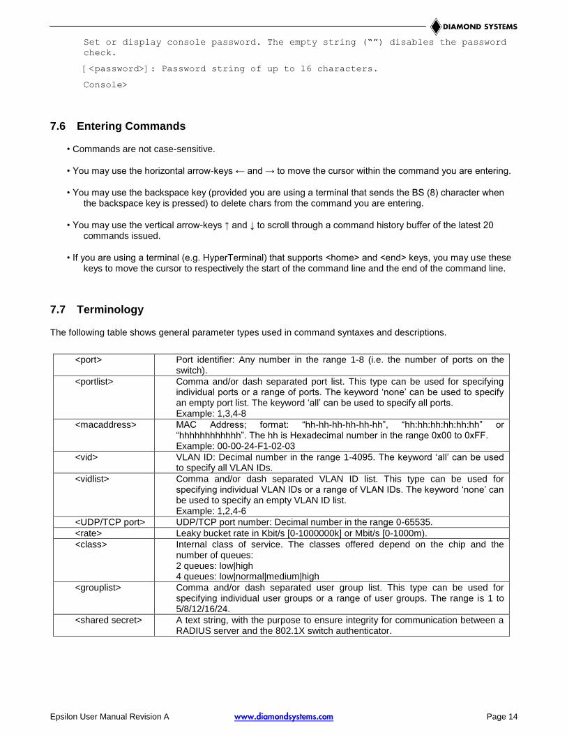
7.7 Terminology
The following table shows general parameter types used in command syntaxes and descriptions.
<port> Port identifier: Any number in the range 1-8 (i.e. the number of ports on the switch).
<portlist> Comma and/or dash separated port list. This type can be used for specifying individual ports or a range of ports. The keyword ‘none’ can be used to specify an empty port list. The keyword ‘all’ can be used to specify all ports. Example: 1,3,4-8
<macaddress> MAC Address; format: “hh-hh-hh-hh-hh-hh”, “hh:hh:hh:hh:hh:hh” or “hhhhhhhhhhhh”. The hh is Hexadecimal number in the range 0x00 to 0xFF. Example: 00-00-24-F1-02-03
<vid> VLAN ID: Decimal number in the range 1-4095. The keyword ‘all’ can be used to specify all VLAN IDs.
<vidlist> Comma and/or dash separated VLAN ID list. This type can be used for specifying individual VLAN IDs or a range of VLAN IDs. The keyword ‘none’ can be used to specify an empty VLAN ID list. Example: 1,2,4-6
<UDP/TCP port> UDP/TCP port number: Decimal number in the range 0-65535.
<rate> Leaky bucket rate in Kbit/s [0-1000000k] or Mbit/s [0-1000m).
<class> Internal class of service. The classes offered depend on the chip and the number of queues: 2 queues: low|high 4 queues: low|normal|medium|high
<grouplist> Comma and/or dash separated user group list. This type can be used for specifying individual user groups or a range of user groups. The range is 1 to 5/8/12/16/24.
<shared secret> A text string, with the purpose to ensure integrity for communication between a RADIUS server and the 802.1X switch authenticator.

Epsilon User Manual Revision A www.diamondsystems.com Page 15
The <portlist> type is very useful when setting up multiple ports in the same mode. For example, the following commands will divide the ports into two untagged VLANs and enable VLAN awareness:
vlan add 1 1-4
vlan add 2 5-8
vlan pvid 1-4 1
vlan pvid 5-8 2
vlan aware all enable
7.8 Changing the IP Address
The board is shipped with an IP address of 192.168.1.60 and the IP mode enabled. This allows the WEB interface to be accessed at that address.
The ip setup command can be used to change the IP address to the desired value: IP Setup [ipaddress> [<ipmask> [ipgateway>]]] [<vid>]
The IP address, mask and gateway must be set according to your environment or you can enable IP and DHCP if your environment include a DHCP server. For example:
>ip setup 10.10.129.189 255.255.252.0 10.10.128.14 1
>ip mode enable
7.9 Command Overview
?
Help
Up
Exit
System Configuration [all]
System Restore Default [keepIP]
System Name [<name>]
System Reboot
System SNMP [enable|disable]
System Trap [<IP Address>]
System Readcommunity [<community string>]
System Writecommunity [<community string>]
System Trapcommunity [<community string>]
System Power Saving [full|up|down|disable]
Console Configuration
Console Password [<password>]
Console Timeout [<timeout>]
Console Prompt [<prompt string>]
Port Configuration [<portlist>]
Port Mode [<portlist>] [<mode>]
Port Flow Control [<portlist>] [enable|disable]
Port State [<portlist>] [enable/disable]
Port MaxFrame [<portlist>] [<framesize>|reset]
Port Statistics [<portlist>] [clear]
Port Excessive Collisions Drop [enable|disable]
Port VeriPHY [<portlist>] [full|anomaly|termination]
MAC Configuration
MAC Add <macaddress> <portlist>|none [<vid>]
MAC Delete <macaddress> [<vid>]
MAC Lookup <macaddress> [<vid>]
MAC table <vidlist>

Epsilon User Manual Revision A www.diamondsystems.com Page 16
MAC Flush
MAC Agetime [<agetime>]
VLAN Configuration [<portlist>]
VLAN Add <vidlist> [<portlist>]
VLAN Delete <vidlist>
VLAN Lookup <vidlist>
VLAN Aware [<portlist>] [enable|disable]
VLAN PVID [<portlist>] [<vid>|none]
VLAN Frame Type [<portlist>] [all|tagged]
VLAN Ingress Filtering [<portlist>] [enable|disable]
Aggr Configuration
Aggr Add <portlist>
Aggr Delete <portlist>
Aggr Lookup <portlist>
Aggr Mode [smac|dmac|xor]
Lacp Configuration [<portlist>]
Lacp Mode [<portlist>] [enable|disable]
Lacp Key [<portlist>] [<key>|auto]
Lacp Status
Lacp Statistics
Rstp Configuration [<portlist>]
Rstp sysprio [<sysprio>]
Rstp hellotime [<secs>]
Rstp maxage [<hops>]
Rstp fwddelay [<secs>]
Rstp version [normal|compat]
Rstp Mode [<portlist>] [enable|disable]
Rstp Aggr [enable|disable]
Rstp Edge [<portlist>] [enable|disable]
Rstp Pathcost [<portlist>] [<pathcost>|auto]
Rstp mcheck <portlist>
Rstp Status
Rstp Statistics
UserGroup Configuration
User Group Add <grouplist> [<portlist>]
User Group Delete <grouplist>
User Group Lookup <grouplist>
QoS Configuration [<portlist>]
QoS Mode [<portlist>] [tag|port|diffserv]
QoS Default [<portlist>] [low|high]
QoS Tagprio [<portlist>] [<tagpriolist>] [<class>]
QoS DiffServ [<portlist>] [<dscplist>] [low|high]
QoS Userprio [<portlist>] [<tagprio>]
QoS Storm Control [<traffic type>] [enable|disable] [<rate>]
Mirror Configuration
Mirror Port [<port>]
Mirror Source [<portlist>] [enable|disable]
IP Configuration
IP Status
IP Setup [<ipaddress> [<ipmask> [<ipgateway>]]] [<vid>]

Epsilon User Manual Revision A www.diamondsystems.com Page 17
IP Mode [enable|disable]
IP Ping [-n <count>] [-w <timeout>] <ipaddress>
IP ARP
IP DHCP [enable|disable]
Dot1x Configuration
Dot1x Mode [enable|disable]
Dot1x State [<portlist>] [Auto|ForceAuthorized|ForceUnauthorized]
Dot1x Server [<IP Address>]
Dot1x UDP Port [<value>]
Dot1x Secret [<Shared Secret>]
Dot1x Statistics [<portlist>]
Dot1x Reauthenticate [<portlist>] [now]
Dot1x Parameters [<parameter>] [<value>]
An IGMP snooping module has been implemented. When enabled, the module snoops on host IGMP membership reports, and controls IP multicast forwarding using entries in the MAC table.
The following commands are available:
IGMP Configuration
IGMP Status
IGMP Groups <vidlist>
IGMP Mode [enable|disable]
IGMP State <vidlist> [enable|disable]
IGMP Querier <vidlist> [enable|disable]
IGMP Router ports [<portlist>] [enable|disable]
IGMP Unregistered Flood [enable|disable]
7.10 Detailed Command Description
Some of the commands have optional parameters. If the optional parameter is omitted, a default value may be used or the command may display the current setting (i.e. function as a get command).
Example 1, omitted parameter interpreted as display command:
Syntax: System Name [<name>]
>system name <enter>
System Name: SuperSwitch-01
Example 2, omitted parameter interpreted as default value (VLAN ID 1):
Syntax: MAC Add <macaddress> <portlist> [<vid>]
>mac add 010203ABCDEF 16 <enter>
The following sections list the individual commands by showing the syntax and a description of each command.

Epsilon User Manual Revision A www.diamondsystems.com Page 18
7.10.1 System Commands
7.10.1.1 SYSTEM CONFIGURATION
Syntax: System Configuration [all]
Description: Show system name, software version, hardware version and management MAC address. Option-ally show the full configuration
[all]: Show the total switch configuration (default: System configuration only).
7.10.1.2 SYSTEM RESTORE DEFAULT
Syntax: System Restore Default [keepIP]
Description: Restore factory default configuration.
[keepIP]: Preserve IP configuration (default: Not preserved).
7.10.1.3 SYSTEM NAME
Syntax: System Name [<name>]
Description: Set or show the system name. The empty string (“”) clears the system name.
[<name>]: String of up to 16 characters (default: Show system name).
7.10.1.4 SYSTEM REBOOT
Syntax: System Reboot
Description: Reboot the switch.
7.10.1.5 SYSTEM SNMP
Syntax: System SNMP [enable|disable]
Description: Activate or deactivate SNMP.
[enable|disable]: Enable/disable SNMP (default: Show SNMP mode).
7.10.1.6 SYSTEM TRAP
Syntax: System Trap [<IP Address>]
Description: Set or show SNMP traps destination.
[<IP Address>]: IP address to send traps to. 0.0.0.0 disables traps (default: Show trap destination).
7.10.1.7 SYSTEM READCOMMUNITY
Syntax: Readcommunity [<community string>]
Description: Set or show SNMP read community string.
[<community string>]: New community string. (default: Show current value).
7.10.1.8 SYSTEM WRITECOMMUNITY
Syntax: Writecommunity [<community string>]
Description: Set or show SNMP write community string.
[<community string>]: New community string. (default: Show current value).
7.10.1.9 SYSTEM TRAPCOMMUNITY
Syntax: Trapcommunity [<community string>]
Description: Set or show SNMP trap community string.
[<community string>]: New community string. (default: Show current value).

Epsilon User Manual Revision A www.diamondsystems.com Page 19
7.10.1.10 SYSTEM POWER SAVING
Syntax: Power Saving [full|up|down|disable]
Description: Configure mode of power saving.
[full]: Power saving at both link-up and link-down.
[up]: Power saving at link-up only.
[down]: Power saving at link-down only.
[disable]: No power saving.
7.10.2 Console Commands
7.10.2.1 CONSOLE CONFIGURATION
Syntax: Console Configuration
Description: Show configured console password and timeout.
7.10.2.2 CONSOLE PASSWORD
Syntax: Console Password [<password>]
Description: Set or show the console password. The empty string (“”) disables the password check.
[<password>]: Password string of up to 16 characters.
7.10.2.3 CONSOLE TIMEOUT
Syntax: Console Timeout [<timeout>]
Description: Set or show the console inactivity timeout in seconds. The value zero disables timeout.
[<timeout>]: Timeout value in seconds, 0, 60-10000.
7.10.2.4 CONSOLE PROMPT
Syntax: Console Prompt [<prompt_string>]
Description: Set or show the console prompt string. The empty string (“”) clears the prompt string.
[<prompt_string>]: Command prompt string of up to 10 characters.
7.10.3 Port Commands
7.10.3.1 PORT CONFIGURATION
Syntax: Port Configuration [<portlist>]
Description: Show the configured and current speed, duplex mode, flow control mode and state for the port.
<portlist>: Port list (default: All ports).
7.10.3.2 PORT MODE
Syntax: Port Mode [<portlist>] [<mode>]
Description: Set or show the speed and duplex mode for the port.
<portlist>: Port list (default: All ports).
<mode> : Port speed and duplex mode (default: Show configured and current mode).
10hdx : 10 Mbit/s, half duplex.
10fdx : 10 Mbit/s, full duplex.
100hdx : 100 Mbit/s, half duplex.
100fdx : 100 Mbit/s, full duplex.
1000fdx: 1 Gbit/s, full duplex.
auto : Auto negotiation of speed and duplex.
Epsilon User Manual Revision A www.diamondsystems.com Page 20
7.10.3.3 PORT FLOW CONTROL
Syntax: Port Flow Control [<portlist>] [enable|disable]
Description: Set or show flow control mode for the port.
<portlist> : Port list (default: All ports).
[enable|disable]: Enable/disable flow control (default: Show flow control mode).
7.10.3.4 PORT STATE
Syntax: Port State [<portlist>] [enable/disable]
Description: Set or show the state for the port.
<portlist> : Port list (default: All ports).
[enable|disable]: Enable or disable port state (default: Show state).
7.10.3.5 PORT MAXFRAME
Syntax: Port MaxFrame [<portlist>] [<framesize>|reset]
Description: Set or show the maximum frame size in bytes (including FCS) for frames received on the port. Tagged frames are allowed to be 4 bytes longer than the maximum frame size. Use the reset option to return to the default setting.
[<portlist>] : Port list (default: All ports).
[<framesize>|reset]: Maximum frame size or reset to 1518 bytes (default: Show maximum frame size).
7.10.3.6 PORT STATISTICS
Syntax: Port Statistics [<portlist>] [clear]
Description: Show or clear statistics for the port.
<portlist>: Port list (default: All ports).
[clear] : Clear port statistics (default: Show statistics).
7.10.3.7 PORT EXCESSIVE COLLISIONS DROP
Syntax: Port Excessive Collisions Drop [enable/disable]
Description: Enable or disable drop of frames when excessive collisions occur in half duplex mode.
[enable|disable]: Enable/disable frame drop (default: Show Excessive Collisions Drop Mode).
7.10.3.8 PORT VERIPHY
Syntax: Port VeriPHY [<portlist>] [full|anomaly|termination]
Description: Perform VeriPHY cable diagnostics on the specified port(s).
<portlist>: Port list (default: All ports).
[full|anomaly|termination] : Type of diagnostics. Full comprises cable length and full anomaly check, anomaly comprises full anomaly check and termination comprises anomaly check without check for coupling between pairs (default: full).
7.10.4 MAC Table Commands
7.10.4.1 MAC CONFIGURATION
Syntax: MAC Configuration
Description: Show the permanently stored MAC table and the MAC ageing timer.
Epsilon User Manual Revision A www.diamondsystems.com Page 21
7.10.4.2 MAC ADD
Syntax: MAC Add <macaddress> <portlist>|none [<vid>]
Description: Add a static MAC address table entry and VLAN ID on ports.
<macaddress>: MAC address, 12-digit hex string, optionally separated with dashes or colons (e.g. 010203ABCDEF or 01-02-03-AB-CD-EF or 01:02:03:AB:CD:EF).
<portlist> : Port list. Use ”none” to specify no ports.
[<vid>] : VLAN ID, 1-4095 (default: 1).
7.10.4.3 MAC DELETE
Syntax: MAC Delete <macaddress> [<vid>]
Description: Delete MAC address and VLAN ID.
<macaddress>: MAC address, 12-digit hex string, optionally separated with dashes or colons (e.g. 010203ABCDEF or 01-02-03-AB-CD-EF or 01:02:03:AB:CD:EF).
[<vid>] : VLAN ID (default: 1).
7.10.4.4 MAC LOOKUP
Syntax: MAC Lookup <macaddress> [<vid>]
Description: Lookup MAC address and VLAN ID.
<macaddress>: MAC address, 12-digit hex string, optionally separated with dashes or colons (e.g. 010203ABCDEF or 01-02-03-AB-CD-EF or 01:02:03:AB:CD:EF).
[<vid>] : VLAN ID, 1-4095 (default: 1).
7.10.4.5 MAC TABLE
Syntax: MAC Table <vidlist>
Description: Show MAC table for the VLAN Ids specified. Since the list can be very long, only the first 20 entries are shown.
<vidlist> : VLAN ID list.
7.10.4.6 MAC FLUSH
Syntax: MAC Flush
Description: Removes non-static MAC address table entries.
7.10.4.7 MAC AGE TIME
Syntax: MAC Agetime [<agetime>]
Description: Set or show the MAC age timer in seconds. The value zero disables ageing.
[<agetime>]: Age timer in seconds, 0 or 10-65535 (default: Show timer).
7.10.5 VLAN Commands
7.10.5.1 VLAN CONFIGURATION
Syntax: VLAN Configuration [<portlist>]
Description: Show the VLAN aware mode, port VLAN ID and accepted frame type for the port and the perma-nently stored VLAN table.
[<portlist>]: Port list (default: All ports).
7.10.5.2 VLAN ADD
Syntax: VLAN Add <vidlist> [<portlist>]
Description: Add VLAN entry and include ports in member set.
<vidlist> : VLAN ID list.
[<portlist>]: Port list (default: All ports).
Epsilon User Manual Revision A www.diamondsystems.com Page 22
7.10.5.3 VLAN DELETE
Syntax: VLAN Delete <vidlist>
Description: Delete VLAN entry (all ports excluded from member set).
<vidlist> : VLAN ID list.
7.10.5.4 VLAN LOOKUP
Syntax: VLAN Lookup <vidlist>
Description: Lookup VLAN entry and show port list.
<vidlist> : VLAN ID list.
7.10.5.5 VLAN AWARE
Syntax: VLAN Aware [<portlist>] [enable|disable]
Description: Set or show the VLAN awareness mode for the port. VLAN aware ports will strip the VLAN tag from received frames and insert the tag in transmitted frames (except PVID). VLAN unaware ports will not strip the tag from received frames or insert the tag in transmitted frames.
[<portlist>]: Port list (default: All ports).
[enable|disable]: Enable/disable VLAN awareness (default: Show awareness).
7.10.5.6 VLAN PVID
Syntax: VLAN PVID [<portlist>] [<vid>|none]
Description: Set or show the port VLAN ID. Untagged frames received on the port will be classified to this VLAN ID. Frames classified to this VLAN ID will be sent untagged on the port.
[<portlist>]: Port list (default: All ports).
[<vid>|none]: Port VLAN ID, 1-4095 (default: Show PVID).
The ’none’ option can be used for trunk links.
7.10.5.7 VLAN FRAME TYPE
Syntax: VLAN Frame Type [<portlist>] [all|tagged]
Description: Set or show the accepted frame type for the port.
[<portlist>]: Port list (default: All ports).
[all|tagged]: Accept all or only tagged (default: Show frame type).
7.10.5.8 VLAN INGRESS FILTERING
Syntax: VLAN Ingress Filtering [<portlist>] [enable|disable]
Description: Set or show VLAN ingress filtering for the port.
[<portlist>]: Port list (default: All ports).
[enable|disable]: Enable or disable VLAN ingress filtering (default: Show current setting).
7.10.6 Aggregation/Trunking Commands
7.10.6.1 AGGREGATION CONFIGURATION
Syntax: Aggr Configuration
Description: Shows the aggregation groups and the aggregation mode.
7.10.6.2 AGGREGATION ADD
Syntax: Aggr Add <portlist>
Description: Add link aggregation group including ports.
<portlist>: Aggregation port list.

Epsilon User Manual Revision A www.diamondsystems.com Page 23
7.10.6.3 AGGREGATION DELETE
Syntax: Aggr Delete <portlist>
Description: Delete link aggregation group.
<portlist>: Port list. Aggregations including any of the ports will be deleted.
7.10.6.4 AGGREGATION LOOKUP
Syntax: Aggr Lookup <portlist>
Description: Lookup and display link aggregation group.
<portlist>: Port list. Aggregations including any of the ports will be shown.
7.10.6.5 AGGREGATION MODE
Syntax: Aggr Mode [smac|dmac|xor]
Description: Set or show link aggregation traffic distribution mode.
[smac|dmac|xor]: Aggregation mode, SMAC, DMAC or XOR (default: Show mode).
7.10.7 LACP Commands
LACP (IEEE 802.3ad Link Aggregation Protocol) provides a way to set up aggregation automatically between switches.
7.10.7.1 LACP CONFIGURATION
Syntax: LACP Configuration [<portlist>]
Description: Show the configuration of LACP on all or some ports.
<portlist>: Port list. Default is all ports.
7.10.7.2 LACP MODE
Syntax: LACP mode [portlist] [enable|disable]
Description: Enable or disable LACP on all or some ports.
<portlist>: List of ports to enable or disable LACP. Default is all ports.
[enable|disable]: Enable or disable LACP on the ports.
7.10.7.3 LACP KEY
Syntax: LACP key [<portlist>] [<key>|auto]
Description: The key determines which ports potentially can aggregate together.
7.10.7.4 LACP STATUS
Syntax: LACP Status
Description: Show LACP group and port status.
7.10.7.5 LACP STATISTICS
Syntax: LACP Statistics
Description: Show LACP protocol port statistics.
7.10.8 RSTP Commands
RSTP is a protocol that prevents loops in the network and dynamically reconfigures which physical links in a switch should forward frames.
7.10.8.1 RSTP CONFIGURATION
Syntax: RSTP Configuration [<portlist>]
Description: Show the RSTP Configuration.

Epsilon User Manual Revision A www.diamondsystems.com Page 24
7.10.8.2 RSTP SYSPRIO
Syntax: RSTP Sysprio [<sysprio>]
Description: Set or show the RSTP system priority.
<sysprio>: Number between 0 and 61440 in increments of 4096. This provides for 16 distinct values: 0, 4096, 8192, 12288, 16384, 20480, 24576, 28672, 32768, 36864, 40960, 45056, 49152, 53248, 57344 and 61440.
The lower the system priority the more likely the switch is to become root in Spanning tree.
7.10.8.3 RSTP HELLOTIME
Syntax: RSTP Hellotime [<secs>]
Description: Set or show the RSTP Hellotime value.
<secs>: Number between 1 - 10 (default is 2)
7.10.8.4 RSTP MAXAGE
Syntax: RSTP Maxage [<secs>]
Description: Set or show the RSTP MaxAge value.
<secs>: Number between 6 - 40 (default is 20)
7.10.8.5 RSTP FWDDELAY
Syntax: RSTP Fwddelay [<secs>]
Description: Set or show the RSTP Forward Delay value.
<secs>: Number between 4 - 30 (default is 15)
7.10.8.6 RSTP VERSION
Syntax: RSTP Version [<version>]
Description: Set or show the RSTP default protocol version to use.
<version>: normal - use RSTP, compat - compatible with old STP
7.10.8.7 RSTP MODE
Syntax: RSTP Mode [<portlist>] [enable|disable]
Description: Set or show the RSTP mode for the designated ports.
[<portlist>]: Port list (default: All ports).
[enable|disable]: Enable or disable.
7.10.8.8 RSTP AGGR
Syntax: RSTP Aggr [enable|disable]
Description: Set or show the RSTP mode for aggregated links.
[enable|disable]: Enable or disable.
7.10.8.9 RSTP EDGE
Syntax: RSTP edge [enable|disable]
Description: Expect the port to be an edge port (an end station) or a link to another STP device.
[enable|disable]: End-station or bridge.
7.10.8.10 RSTP PATHCOST
Syntax: RSTP pathcost [<portlist>] [<pathcost>|auto]
Description: Set or show the RSTP path cost for the designated ports.
[<portlist>]: Port list (Default: All ports).
[<pathcost>]: Number between 1 - 200000000. Auto means autogenerated pathcost
Pathcost is normally reverse proportional to the physical (or aggregated) link speed.

Epsilon User Manual Revision A www.diamondsystems.com Page 25
7.10.8.11 RSTP MCHECK
Syntax: RSTP Mcheck <portlist>
Description: Force protocol renegotiations on the specified ports.
<portlist>: Port list.
7.10.8.12 RSTP STATUS
Syntax: RSTP Status
Description: Show the current state of all RSTP incarnations and the physical (and aggregation) ports that they control.
7.10.8.13 RSTP STATISTICS
Syntax: RSTP Statistics
Description: Show the current statistics of all RSTP BPDU frames received and transmitted on the physical (and aggregation) ports.
7.10.9 User Group Commands
User groups provide another way than VLAN for making port grouping. With user groups it is possible to share a port between more user groups. An example on how to use user groups is given in chapter 3.5.
7.10.9.1 USER GROUP CONFIGURATION
Syntax: User Group Configuration
Description: Show the user groups.
7.10.9.2 USER GROUP ADD
Syntax: User Group Add <grouplist> [<portlist>]
Description: Add user group entry including the ports.
<grouplist> : User group ID list.
[<portlist>]: Port list (default: All ports).
7.10.9.3 USER GROUP DELETE
Syntax: User Group Delete <grouplist>
Description: Delete user group entry.
<grouplist>: User group ID list.
7.10.9.4 USER GROUP LOOKUP
Syntax: User Group Lookup <grouplist>
Description: Lookup user group entry and show port members.
<groupist>: User group ID list.
7.10.10 QoS Commands
7.10.10.1 QOS CONFIGURATION
Syntax: QoS Configuration [<portlist>]
Description: Show the configured QoS mode, IP ToS Precedence priority mapping, VLAN user priority map-ping, default priority, default VLAN user priority, L4 default priority, L4 match priority and UDP/ TCP entries for the port.
[<portlist>] : Port list (default: All ports).

Epsilon User Manual Revision A www.diamondsystems.com Page 26
7.10.10.2 QOS MODE
Syntax: QoS Mode [<portlist>] [tag|port|diffserv]
Description: Set or show the priority mode for the port.
[<portlist>] : Port list (default: All ports).
[tag|diffserv]: Enable tag or IP differentiated services for the port (default: Show mode).
7.10.10.3 QOS DEFAULT
Syntax: QoS Default [<portlist>] [<class>]
Description: Set or show the default class. In tag mode, the default class is used for untagged frames. In port mode, the default class is used as the port priority. In the other modes, the default class is used for non-IP frames and IP frames with options.
[<portlist>]: Port list (default: All ports).
[<class>] : Internal class of service (default: Show class).
7.10.10.4 QOS TAGPRIO
Syntax: QoS Tagprio [<portlist>] [<tagpriolist>] [<class>]
Description: Set or show the VLAN user priority mapping.
[<portlist>] : Port list (default: All ports).
[<tagpriolist>]: VLAN user priority list, 0-7 (default: All user priorities).
[<class>] : Internal class of service (default: Show class).
7.10.10.5 QOS DIFFSERV
Syntax: QoS DiffServ [<dscplist>] [<class>]
Description: Set or show the IP Differentiated Services mapping.
[<dscplist>]: IP DSCP list, 0-63 (default: All DSCP values).
[<class>] : Internal class of service (default: Show class).
Constraint: only takes a single DSCP number as parameter instead of a DSCP list.
7.10.10.6 QOS USERPRIO
Syntax: QoS Userprio [<portlist>] [<tagprio>]
Description: Set or show the default VLAN user priority for received untagged frames.
[<portlist>]: Port list (default: All ports).
[<tagprio>] : VLAN tag user priority, 0-7 (default: Show user priority).
7.10.10.7 QOS STORM CONTROL
Syntax: QoS Storm Control <traffic type> [enable|disable] [<rate>]
Description: Set or show the storm control configuration. The allowed frame rates for multicasts, broadcasts and flooded unicasts are controlled using a central storm controller.
<traffic type> : Storm controller to set. Can be one of [Broadcast|Multicast|Flood Unicast] (default: Show all).
[enable|disable] : Enable or disable specified storm controller.
[<rate>] : Unit is 1982 frames per second. Allowed values are 1982, 2*1982, 3*1982, … 127*1982
7.10.11 Mirror Commands
7.10.11.1 MIRROR CONFIGURATION
Syntax: Mirror Configuration
Description: Show the mirror destination port and mirror mode for source ports.

Epsilon User Manual Revision A www.diamondsystems.com Page 27
7.10.11.2 MIRROR PORT
Syntax: Mirror Port [<port>]
Description: Set or show the mirror destination port.
[<port>]: Mirror destination port (default: Show mirror port).
7.10.11.3 MIRROR SOURCE
Syntax: Mirror Source [<portlist>] [enable|disable]
Description: Set or show the source port mirror mode.
[<portlist>] : Source port list (default: All ports).
[enable|disable]: Enable/disable mirroring of frames received on port (default: Show mirror mode).
7.10.12 IP Commands
The TFTP related commands in below are not supported by all versions. From 2.33, they are not supported anymore.
7.10.12.1 IP CONFIGURATION
Syntax: IP Configuration
Description: Show configured IP address, mask, gateway, VLAN ID and mode.
7.10.12.2 IP STATUS
Syntax: IP Status
Description: Show current IP status. Not implemented
7.10.12.3 IP SETUP
Syntax: IP Setup [ipaddress> [<ipmask> [ipgateway>]]] [<vid>]
Description: Set or show IP configuration.
[<ipaddress>]: IP address (default: Show IP configuration).
[<ipmask>] : IP subnet mask (default: Subnet mask for address class).
[<ipgateway>]: Default IP gateway (default: 0.0.0.0).
[<vid>] : VLAN ID, 1-4095 (default: 1).
7.10.12.4 IP MODE
Syntax: IP Mode [enable|disable]
Description: Activate or deactivate the IP configuration.
[enable|disable]: Enable/disable IP (default: Show IP mode).
7.10.12.5 IP PING
Syntax: IP Ping [-n <count>][-w <timeout>] <ipaddress>
Description: Ping the specified IP address.
[-n <count>]: Number of echo requests to send (default: 1).
[-w <timeout>]: Timeout in seconds to wait for each reply (default: 2).
7.10.12.6 IP ARP
Syntax: IP Arp
Description: Show the current content of the ARP table.
7.10.12.7 IP DHCP
Syntax: IP Dhcp [enable|disable]
Description: Activate or deactivate the DHCP Protocol.
[enable|disable]: Enable/disable DHCP (default: Show DHCP mode).

Epsilon User Manual Revision A www.diamondsystems.com Page 28
7.10.13 Dot1X Commands
7.10.13.1 DOT1X CONFIGURATION
Syntax: Dot1x Configuration
Description: Show current 802.1X configuration.
7.10.13.2 DOT1X MODE
Syntax: Dot1x Mode [enable|disable]
Description: Enable or disable 802.1X process for the switch.
[enable|disable]: new mode (default: Show current configuration).
7.10.13.3 DOT1X STATE
Syntax: Dot1x State [<portlist>] [Auto|ForceAuthorized|ForceUnauthorized]
Description: Set or show the 802.1X state for the port.
[<portlist>] : Port list (default: All ports).
[Auto|ForceAuthorized|ForceUnauthorized]: Set 802.1X state for the ports (default: Show mode).
7.10.13.4 DOT1X SERVER
Syntax: Dot1x Server [<IP Address>]
Description: Set or show RADIUS server IP address.
[<IP Address>]: IP address of external RADIUS server. (default: Show current configuration)
7.10.13.5 DOT1X UDP PORT
Syntax: Dot1x UDP Port [<value>]
Description: Set up UDP Port for the external RADIUS server.
[<value>]: The UDP port the RADIUS server listens to (default: Show current configuration).
7.10.13.6 DOT1X SECRET
Syntax: Dot1x Secret [<Shared Secret>]
Description: Set or show the secret shared with the RADIUS server.
[<Shared Secret>]: Shared secret shared with external RADIUS server. (default: Show current configuration)
7.10.13.7 DOT1X STATISTICS
Syntax: Dot1x Statistics [<portlist>]
Description: Show 802.1X statistics for the port.
[<portlist>]: Port list (default: All ports).
7.10.13.8 DOT1X REAUTHENTICATE
Syntax: Dot1x Reauthenticate [<portlist>] [now]
Description: Refresh (restart) 802.1X authentication process for the port by setting reAuthenticate TRUE.
[<portlist>]: Port list (default: All ports).
[now]: if specified, force re-authentication immediately.
7.10.13.9 DOT1X PARAMETERS
Syntax: Dot1X Parameters [<parameter>] [<value>]
Description: Set up advanced 802.1X parameters.
[<parameter>]: Parameter to change.
[<value>]: New value for the given parameter.
Epsilon User Manual Revision A www.diamondsystems.com Page 29
7.10.14 IGMP Snooping Commands
7.10.14.1 IGMP SNOOPING DESCRIPTION
Per default – and when enabled - IGMP snooping will function in each statically defined VLAN (i.e. those VLANs that are stored in non-volatile configuration memory). The IGMP snooping module will listen to IP multicast router IGMP queries and the IGMP reports from hosts, and will update the switch device MAC table with IP multicast group MAC addresses and port masks according to the received reports. If no IP multicast router is present in an IGMP enabled VLAN, the switch will perform the querying itself in that particular VLAN.
The switch querying functionality can be enabled and disabled per VLAN. The switch must be setup for IP management in order for the querying to work.
7.10.14.2 IGMP CONFIGURATION
Syntax: IGMP Configuration
Description: Show the IGMP configuration.
7.10.14.3 IGMP STATUS
Syntax: IGMP Status
Description: Show the IGMP operational status and statistics.
7.10.14.4 IGMP GROUPS
Syntax: IGMP Groups <vidlist>
Description: Show IGMP groups for given VLANs.
7.10.14.5 IGMP MODE
Syntax: IGMP Mode [enable|disable]
Description: Set or show global IGMP mode.
(default: Show current mode)
7.10.14.6 IGMP STATE
Syntax: IGMP State <vidlist> [enable|disable]
Description: Set or Show IGMP state per VLAN.
(default: Show IGMP state)
7.10.14.7 IGMP QUERIER
Syntax: IGMP Querier <vidlist> [enable|disable]
Description: Set or Show IGMP querier state per VLAN.
(default: Show IGMP querier state)
7.10.14.8 ROUTER PORTS
Syntax: IGMP Router ports [<portlist>] [enable|disable]
Description: Set or show IGMP administrative router ports.
(default: Show current router ports)
7.10.14.9 UNREGISTERED FLOOD
Syntax: IGMP Unregistered Flood [enable|disable]
Description: Set or show forwarding mode for unregistered (not-joined) IP multicast traffic. Will flood when enabled, and forward to router-ports only when disabled
(default: Show current mode)
7.10.15 Debug Commands
The Debug commands are for factory use only.
Epsilon User Manual Revision A www.diamondsystems.com Page 30
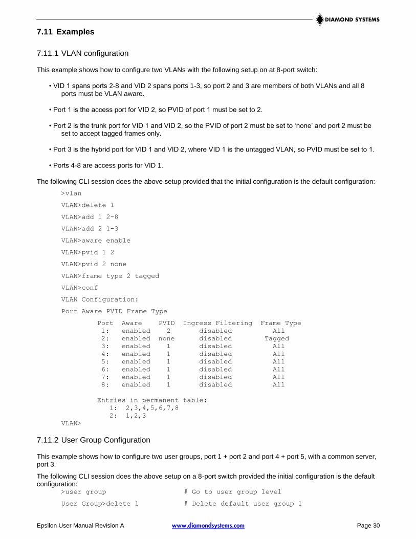
7.11 Examples
7.11.1 VLAN configuration
This example shows how to configure two VLANs with the following setup on at 8-port switch:
• VID 1 spans ports 2-8 and VID 2 spans ports 1-3, so port 2 and 3 are members of both VLANs and all 8 ports must be VLAN aware.
• Port 1 is the access port for VID 2, so PVID of port 1 must be set to 2.
• Port 2 is the trunk port for VID 1 and VID 2, so the PVID of port 2 must be set to ‘none’ and port 2 must be set to accept tagged frames only.
• Port 3 is the hybrid port for VID 1 and VID 2, where VID 1 is the untagged VLAN, so PVID must be set to 1.
• Ports 4-8 are access ports for VID 1.
The following CLI session does the above setup provided that the initial configuration is the default configuration:
>vlan
VLAN>delete 1
VLAN>add 1 2-8
VLAN>add 2 1-3
VLAN>aware enable
VLAN>pvid 1 2
VLAN>pvid 2 none
VLAN>frame type 2 tagged
VLAN>conf
VLAN Configuration:
Port Aware PVID Frame Type
Port Aware PVID Ingress Filtering Frame Type
1: enabled 2 disabled All
2: enabled none disabled Tagged
3: enabled 1 disabled All
4: enabled 1 disabled All
5: enabled 1 disabled All
6: enabled 1 disabled All
7: enabled 1 disabled All
8: enabled 1 disabled All
Entries in permanent table:
1: 2,3,4,5,6,7,8
2: 1,2,3
VLAN>
7.11.2 User Group Configuration
This example shows how to configure two user groups, port 1 + port 2 and port 4 + port 5, with a common server, port 3.
The following CLI session does the above setup on a 8-port switch provided the initial configuration is the default configuration:
>user group # Go to user group level
User Group>delete 1 # Delete default user group 1

Epsilon User Manual Revision A www.diamondsystems.com Page 31
User Group>add 2 1-3 # Create user group with ports 1-3
User Group>add 3 3-5 # Create user group with ports 3-5
User Group>add 1 6-8 # Restore default group excluding ports 1-5
Groups:
1: 6,7,8
2: 1,2,3
3: 3,4,5
8. WEB INTERFACE
The web interface offers an alternate user interface to the CLI. The web interface is in-band and requires use of one of the Ethernet ports. This port provides simultaneous web management and normal usage. The same commands with the same functionality can be accessed via either interface. Refer to Section 7 for specific command information.
From the WEB interface it is possible to, among other things: Set port mode Enable/disable flow control Configure simple port-based VLAN Configure aggregation groups Configure LACP parameters Configure RSTP parameters Configure QoS Read and clear statistics counters Monitor LACP status Monitor RSTP status Configure and monitor 802.1X Configure and monitor IGMP snooping (if defined for switch device) Configure source-IP address and DHCP server filter Upgrade software
All operations are password protected. The password must be entered at login. The password is the same as is being used in the command line interface.
The IP mode is disabled in the factory default configuration. To be able to use the WEB interface, the IP must be enabled and configured via the command line interface. The IP address, mask and gateway must be set according to your environment or you can enable IP and DHCP if your environment include a DHCP server. Example on enabling the WEB interface via the command line interface:
>ip setup 10.10.129.189 255.255.252.0 10.10.128.14 1
>ip mode enable
The web interface and any Ethernet traffic to the internal microcontroller is limited to a size of 1472 bytes.

Epsilon User Manual Revision A www.diamondsystems.com Page 32
9. THERMAL SOLUTIONS
There are two thermal management solutions available for the Epsilon board: heatspreader or heatsink. The choice depends on the temperature range the board will encounter.
9.1 Heatspreader
For the full temperature range (-40°C to +85°C) the recommended solution is the conduction cooling heatspreader plate shown in Figure 3. The plate attaches to Epsilon using the four #4-40 holes in the corner that are also used to attach the board to another PC/104 board. The four #6-32 holes in the plate are used to attach it to the enclosure wall. In the case where there are no fans present, this attachment provides the best path for removing heat.
Figure 3. Epsilon Heatspreader Plate

Epsilon User Manual Revision A www.diamondsystems.com Page 33
9.2 Heatsink
When a fan is present (i.e., there is airflow) or the ambient temperature stays in the range -40°C to +71°C, the recommended solution is the heatsink shown in Figure 4. The heatsink has a lower profile and is better adapted to removing heat from the board when there is airflow.
Figure 4. Epsilon Heatsink

Epsilon User Manual Revision A www.diamondsystems.com Page 34
10. SPECIFICATIONS
The specifications for the boad are summarized in the following table.
Ethernet switch 8-port, layer 2+ switch Built-in 8051 microcontroller for configuration and management
Number of ports 8 10/100/1000Mbps copper Ethernet ports with non-blocking wire-speed performance
On-board memory 2MB flash for boot and application code 128KB SRAM 8KB EEPROM
Frame buffer 176 kilobyte on-chip frame buffer Jumbo frame support at all speeds
DSCP DSCP remarking for both IPv4 and IPv6 frames
Serial port 1 RS-232 for host interface
Indicator LEDS 16 status LEDs, two per port 2 general purpose LEDs
Classifier Programmable multi-layer classifier with 4 QoS classes
RSTP Rapid spanning tree protocol (IEEE 802.1W
Standalone Capable Can operate as a standalone network switch or in combination with a PC/104 embedded computer
Power Input +7-36V DC/DC power supply +5VDC input (either external, from PC/104 bus, or from PC/104-Plus bus)
Power consumption 5.4W typical at +5VDC with all 8 ports active, approx. 0.26W less for each inactive port
Bus interface PC/104 (ISA) bus passthrough
Form factor PC/104 (3.55’ x 3.775”) Height: 16.86mm with heatspreader; 15.7mm with heatsink
Operating temp -40°C to +85°C (-40°F to +185°F) with heatspreader plate or -40°C to +71°C (+40°F to +160°F) with heatsink
Weight 3.4oz (96g) without heatspreader plate or heatsink
RoHS Compliant
The timing specifications for the board are summarized in the following table.
Time to Login and alive LED flashing after power-on, power cycle, or reboot 8 sec.
Time for ports to reconnect after power-on, power cycle, or reboot 15 sec.
Time for all ports to start passing data after power-on, power cycle, or reboot <30 sec. (typical 24-26 sec.)
Time for all ports to start passing data after restoring factory defaults 8 sec.

Epsilon User Manual Revision A www.diamondsystems.com Page 35
APPENDIX A DEFAULT VALUES
When the System Restore Default [keepIP] command is issued, the switch configuration returns to its factory settings. The following lists show the values of the various configuration parameters.
The software version will change with any new application code that is loaded onto the board. The MAC address is unique to the particular board. The IP address is set to 192.168.1.60 in the factory and can be changed by the user. The default value will not change as long as the “keepIP” flag is used in restoring the factory default values.
System Configuration: Name:
S/W Version: Luton 2.34d 2m diamond system
CVS Tag: sw_8051_2_34d
Compile Date: Feb 25 2011 11:35:44
H/W Version: 1.0
MAC address: 00-06-d5-25-10-14 #Unique value for every board
SNMP: enabled
Trap IP: 0.0.0.0
Readcommunity: public
Writecommunity: private
Trapcommunity: public
Console Configuration: Password:
Timeout: 0
Prompt: >
Port Configuration: Port State Mode Flow control Link MaxFrame
1: enabled auto disabled 1000fdx 1518
2: enabled auto disabled 1000fdx 1518
3: enabled auto disabled 1000fdx 1518
4: enabled auto disabled 1000fdx 1518
5: enabled auto disabled 1000fdx 1518
6: enabled auto disabled 1000fdx 1518
7: enabled auto disabled 1000fdx 1518
8: enabled auto disabled 1000fdx 1518
Excessive Collisions Drop: disabled
MAC Configuration: Entries in permanent table:
None
Agetime: 300
VLAN Configuration: Port Aware PVID Ingress Filtering Frame Type
1: disabled 1 disabled All
2: disabled 1 disabled All
3: disabled 1 disabled All
4: disabled 1 disabled All
5: disabled 1 disabled All
6: disabled 1 disabled All
7: disabled 1 disabled All
8: disabled 1 disabled All
Entries in permanent table:
1: 1,2,3,4,5,6,7,8

Epsilon User Manual Revision A www.diamondsystems.com Page 36
Aggr Configuration: Groups:
None
LACP status
None
Mode: xor
Operational Status Groups:
None
LACP Configuration: System Id: 00-06-d5-25-10-14
System Priority: 32768
Port Enabled Key
1 no auto
2 no auto
3 no auto
4 no auto
5 no auto
6 no auto
7 no auto
8 no auto
RSTP Configuration: sysprio: 32768
hellotime: 2
maxage: 20
fwddelay: 15
version: normal
Port Enabled Edge Pathcost
1 no yes auto
2 no yes auto
3 no yes auto
4 no yes auto
5 no yes auto
6 no yes auto
7 no yes auto
8 no yes auto
Aggr no
User Group Configuration: Groups:
1: 1,2,3,4,5,6,7,8
QoS Configuration: Port Mode Default User
1: port high 0
2: port high 0
3: port high 0
4: port high 0
5: port high 0
6: port high 0
7: port high 0
8: port high 0
Tag Priorities:
Port 0 1 2 3 4 5 6 7
1: normal low low normal medium medium high high
2: normal low low normal medium medium high high
3: normal low low normal medium medium high high
4: normal low low normal medium medium high high
5: normal low low normal medium medium high high
6: normal low low normal medium medium high high
7: normal low low normal medium medium high high
8: normal low low normal medium medium high high

Epsilon User Manual Revision A www.diamondsystems.com Page 37
DiffServ:
DSCP Class
All high
Storm Control:
Broadcast: disabled 0
Multicast: disabled 0
Flood Unicast: disabled 0
Mirror Configuration: Mirror Port: 1
Source:
Port 1: disabled
Port 2: disabled
Port 3: disabled
Port 4: disabled
Port 5: disabled
Port 6: disabled
Port 7: disabled
Port 8: disabled
IP Configuration: Address: 192.168.1.60
Subnet Mask: 255.255.255.0
Gateway: 0.0.0.0
VID: 1
Mode: enabled
dhcp: disabled
Dot1x Configuration: Mode: disabled
Port Admin State Port State
1: ForceAuthorized 802.1X Disabled
2: ForceAuthorized 802.1X Disabled
3: ForceAuthorized 802.1X Disabled
4: ForceAuthorized 802.1X Disabled
5: ForceAuthorized 802.1X Disabled
6: ForceAuthorized 802.1X Disabled
7: ForceAuthorized 802.1X Disabled
8: ForceAuthorized 802.1X Disabled
RADIUS Configuration:
Server: 0.0.0.0
UDP Port: 1812
Secret:
IGMP Configuration: Mode: disabled
VID IGMP Snooping Querier
1 enabled enabled
Router ports: None
Unregistered Flood: enabled