Embed Size (px)
Citation preview
EPUAV ‘Red Back’ Collaboration between NUAA, RMIT University
and Carleton University
Stratos Patsikatheodorou
Kelvin Dadhania
Veena Venugopal
Mansi Magoo
Luke Pranskunas
Syed Muhammad Taha Zaidi
11.01.2010

2 | P a g e
Contents
Executive Summary ................................................................................................................................ 5
Nomenclature .......................................................................................................................................... 6
1. Introduction ..................................................................................................................................... 9
2. Design Requirements ...................................................................................................................... 9
2.1. Performance Requirements ..................................................................................................... 9
2.2. Operational Requirements....................................................................................................... 9
2.3. Cost Requirements .................................................................................................................. 9
3. Team Composition .......................................................................................................................... 9
4. Conceptual Design ........................................................................................................................ 10
4.1. Configuration Design ............................................................................................................ 10
4.2. Initial Sizing .......................................................................................................................... 12
4.2.1. Wing .............................................................................................................................. 12
4.2.2. Fuselage ........................................................................................................................ 14
4.2.3. Empennage .................................................................................................................... 15
4.3. Fuselage Layout .................................................................................................................... 16
4.4. Airfoil Design ....................................................................................................................... 18
4.5. Wing Design ......................................................................................................................... 21
4.6. Empennage Design ............................................................................................................... 23
4.7. Landing Gear ........................................................................................................................ 23
4.8. Analysis of Propulsion .......................................................................................................... 23
4.8.1. Aircraft Performance ......................................................................................................... 25
4.9. Weight and C.G. Estimation ................................................................................................. 26
4.10. Aerodynamic Performance ............................................................................................... 30
4.11. Stability Analysis .............................................................................................................. 35
4.12. CAD Definition of the concept ......................................................................................... 36
5. Preliminary Design ....................................................................................................................... 38
5.1. Wing Structure ...................................................................................................................... 38
5.2. Fuselage Structure ................................................................................................................. 40
5.3. Empennage Structure ............................................................................................................ 42
5.4. Control Surface Structure...................................................................................................... 42
5.5. Landing Gear ........................................................................................................................ 42
5.6. Integration of Propulsion System .......................................................................................... 44
3 | P a g e
6. Detail Design ................................................................................................................................ 44
6.1. Fuselage Detail Design ......................................................................................................... 44
6.2. Wing Detail Design ............................................................................................................... 48
6.3. Empennage Detail Design ..................................................................................................... 52
6.3.1. Horizontal Tail: ................................................................................................................. 52
6.3.2. Servo Plate: ....................................................................................................................... 52
6.3.3. Mounting Block: ............................................................................................................... 53
6.3.4. Vertical Tail: ..................................................................................................................... 53
6.3.5. Servo Plate (Vertical): ....................................................................................................... 55
6.4. Control Surface Detail Design .............................................................................................. 55
6.4.1. Elevator: ............................................................................................................................ 55
6.4.2. Rudder: .............................................................................................................................. 56
6.4.3. Aileron: ............................................................................................................................. 56
6.5. Landing Gear Detail Design ................................................................................................. 58
6.6. Control System Design ......................................................................................................... 58
7. Fabrication .................................................................................................................................... 60
7.1. Preparation ............................................................................................................................ 60
7.2. Fuselage Fabrication ............................................................................................................. 60
7.3. Wing Fabrication .................................................................................................................. 62
7.4. Empennage Fabrication......................................................................................................... 65
7.4.1. Mounting Block: ............................................................................................................... 65
7.4.2. Horizontal Stabiliser: ........................................................................................................ 66
7.4.3. Vertical Stabiliser:............................................................................................................. 68
7.4.4. Attachment: ....................................................................................................................... 69
7.4.5. Problems: .......................................................................................................................... 69
7.5. Control Surface Fabrication .................................................................................................. 70
7.5.1. Elevator: ............................................................................................................................ 70
7.5.2. Rudder: .............................................................................................................................. 70
7.5.3. Aileron: ............................................................................................................................. 71
7.6. Landing Gear Fabrication ..................................................................................................... 71
7.7. Installation of Propulsion System and Test ........................................................................... 72
7.8. Control System Installation and Test .................................................................................... 73
7.9. Measurement of Weight and C.G. Location ......................................................................... 74
8. Test ................................................................................................................................................ 74
4 | P a g e
8.1. Test Plan................................................................................................................................ 74
8.2. Ground Test .......................................................................................................................... 74
8.3. Air Test ................................................................................................................................. 75
Appendix A – AVL Text File ............................................................................................................... 78
5 | P a g e
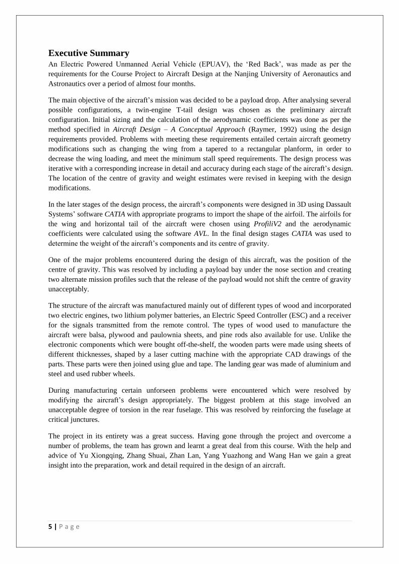
Executive Summary An Electric Powered Unmanned Aerial Vehicle (EPUAV), the ‘Red Back’, was made as per the
requirements for the Course Project to Aircraft Design at the Nanjing University of Aeronautics and
Astronautics over a period of almost four months.
The main objective of the aircraft’s mission was decided to be a payload drop. After analysing several
possible configurations, a twin-engine T-tail design was chosen as the preliminary aircraft
configuration. Initial sizing and the calculation of the aerodynamic coefficients was done as per the
method specified in Aircraft Design – A Conceptual Approach (Raymer, 1992) using the design
requirements provided. Problems with meeting these requirements entailed certain aircraft geometry
modifications such as changing the wing from a tapered to a rectangular planform, in order to
decrease the wing loading, and meet the minimum stall speed requirements. The design process was
iterative with a corresponding increase in detail and accuracy during each stage of the aircraft’s design.
The location of the centre of gravity and weight estimates were revised in keeping with the design
modifications.
In the later stages of the design process, the aircraft’s components were designed in 3D using Dassault
Systems’ software CATIA with appropriate programs to import the shape of the airfoil. The airfoils for
the wing and horizontal tail of the aircraft were chosen using ProfiliV2 and the aerodynamic
coefficients were calculated using the software AVL. In the final design stages CATIA was used to
determine the weight of the aircraft’s components and its centre of gravity.
One of the major problems encountered during the design of this aircraft, was the position of the
centre of gravity. This was resolved by including a payload bay under the nose section and creating
two alternate mission profiles such that the release of the payload would not shift the centre of gravity
unacceptably.
The structure of the aircraft was manufactured mainly out of different types of wood and incorporated
two electric engines, two lithium polymer batteries, an Electric Speed Controller (ESC) and a receiver
for the signals transmitted from the remote control. The types of wood used to manufacture the
aircraft were balsa, plywood and paulownia sheets, and pine rods also available for use. Unlike the
electronic components which were bought off-the-shelf, the wooden parts were made using sheets of
different thicknesses, shaped by a laser cutting machine with the appropriate CAD drawings of the
parts. These parts were then joined using glue and tape. The landing gear was made of aluminium and
steel and used rubber wheels.
During manufacturing certain unforseen problems were encountered which were resolved by
modifying the aircraft’s design appropriately. The biggest problem at this stage involved an
unacceptable degree of torsion in the rear fuselage. This was resolved by reinforcing the fuselage at
critical junctures.
The project in its entirety was a great success. Having gone through the project and overcome a
number of problems, the team has grown and learnt a great deal from this course. With the help and
advice of Yu Xiongqing, Zhang Shuai, Zhan Lan, Yang Yuazhong and Wang Han we gain a great
insight into the preparation, work and detail required in the design of an aircraft.
6 | P a g e
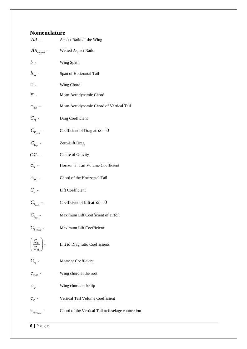
Nomenclature AR - Aspect Ratio of the Wing
wettedAR - Wetted Aspect Ratio
b - Wing Span
horb - Span of Horizontal Tail
c - Wing Chord
c - Mean Aerodynamic Chord
vertc - Mean Aerodynamic Chord of Vertical Tail
DC - Drag Coefficient
0DC
- Coefficient of Drag at 0
ODC - Zero-Lift Drag
C.G. - Centre of Gravity
htc - Horizontal Tail Volume Coefficient
horc - Chord of the Horizontal Tail
LC - Lift Coefficient
0LC
- Coefficient of Lift at 0
maxlC - Maximum Lift Coefficient of airfoil
maxLC - Maximum Lift Coefficient
L
D
C
C
- Lift to Drag ratio Coefficients
mC - Moment Coefficient
rootc - Wing chord at the root
tipc - Wing chord at the tip
vtc - Vertical Tail Volume Coefficient
basevertc - Chord of the Vertical Tail at fuselage connection
7 | P a g e
topvertc - Chord of the Vertical Tail at top most point
D - Drag
e - Oswald Efficiency Factor
doorF - Length of the fuselage rear cargo door section
heightF - Fuselage Height
lengthF - Fuselage Length
noseF - Length of the fuselage nose section
widthF - Fuselage Width
verth - Height of the Vertical Tail
L - Lift
htL - Moment arm of Horizontal Tail
vtL - Moment arm of Vertical Tail
max
L
D
- Maximum Lift to Drag ratio
q - Dynamic Pressure (21
2V )
Re - Reynold’s Number
refS - Reference Area of the Wing
sidefuselageS - Reference area of side of fuselage
topfuselageS - Reference area of top of fuselage
wetfuselageS - Fuselage wetted area
horS - Reference Area of the Horizontal Tail
wethorS - Wetted Area of the Horizontal Tail
TOS - Takeoff Distance
vtS - Reference Area of the Vertical Tail
8 | P a g e
wetvertS - Wetted Area of the Vertical Tail
wet
ref
S
S - Wetted area ratio
maxt - Maximum thickness
t
c
- Thickness ratio
maxV - Maximum level flight velocity
minV - Minimum level flight velocity
stallV - Stall Velocity
fuselageW - Fuselage Weight
horW - Horizontal Tail Weight
PLW - Payload Weight
TOW - Takeoff Weight
wingW - Wing Weight
stall
W
S
- Wing loading at stall
cruise
W
S
- Wing loading at cruise
max - Maximum angle of attack
- Taper ratio
vert - Taper ratio of Vertical Tail
LE - Leading edge sweep angle
4c - Quarter chord sweep angle
9 | P a g e
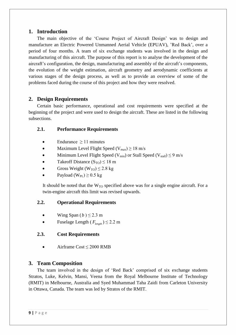
1. Introduction
The main objective of the ‘Course Project of Aircraft Design’ was to design and
manufacture an Electric Powered Unmanned Aerial Vehicle (EPUAV), ’Red Back’, over a
period of four months. A team of six exchange students was involved in the design and
manufacturing of this aircraft. The purpose of this report is to analyse the development of the
aircraft’s configuration, the design, manufacturing and assembly of the aircraft’s components,
the evolution of the weight estimation, aircraft geometry and aerodynamic coefficients at
various stages of the design process, as well as to provide an overview of some of the
problems faced during the course of this project and how they were resolved.
2. Design Requirements
Certain basic performance, operational and cost requirements were specified at the
beginning of the project and were used to design the aircraft. These are listed in the following
subsections.
2.1. Performance Requirements
Endurance ≥ 11 minutes
Maximum Level Flight Speed (Vmax) ≥ 18 m/s
Minimum Level Flight Speed (Vmin) or Stall Speed (Vstall) ≤ 9 m/s
Takeoff Distance (STO) ≤ 18 m
Gross Weight (WTO) ≤ 2.8 kg
Payload (WPL) ≥ 0.5 kg
It should be noted that the WTO specified above was for a single engine aircraft. For a
twin-engine aircraft this limit was revised upwards.
2.2. Operational Requirements
Wing Span ( b ) ≤ 2.3 m
Fuselage Length ( lengthF ) ≤ 2.2 m
2.3. Cost Requirements
Airframe Cost ≤ 2000 RMB
3. Team Composition
The team involved in the design of ‘Red Back’ comprised of six exchange students
Stratos, Luke, Kelvin, Mansi, Veena from the Royal Melbourne Institute of Technology
(RMIT) in Melbourne, Australia and Syed Muhammad Taha Zaidi from Carleton University
in Ottawa, Canada. The team was led by Stratos of the RMIT.
10 | P a g e
In order to maintain consistency throughout the course of the project, it was decided that
the same people would proceed with the development of the design of the same components.
During the initial design phase, the development of the aircraft’s basic configuration and
initial sizing calculations were done by Stratos, Kelvin and Taha who were assisted by Mansi
in the former task. Kelvin developed the layout of the fuselage and worked alongside Taha to
develop the geometry for the landing gear. Veena and Luke developed the design of the
airfoil and the empennage. They were assisted in the latter task by Stratos and Taha who also
developed the design of the wing planform. The analysis of the flight performance, stability
and propulsion as well as initial weight and centre of gravity estimation were carried out by
Kelvin and Taha. They were assisted in the stability analysis by Stratos who also worked with
Luke and Veena to analyse the aerodynamic performance. Luke, Veena, Kelvin and Stratos
also created the initial CAD definition of the aircraft design.
The team helped out all together with the fabrication of the respective parts of the aircraft
over a period of about 3 weeks. This was a crucial stage in which some design challenges and
problems arose, but were eventually overcome.
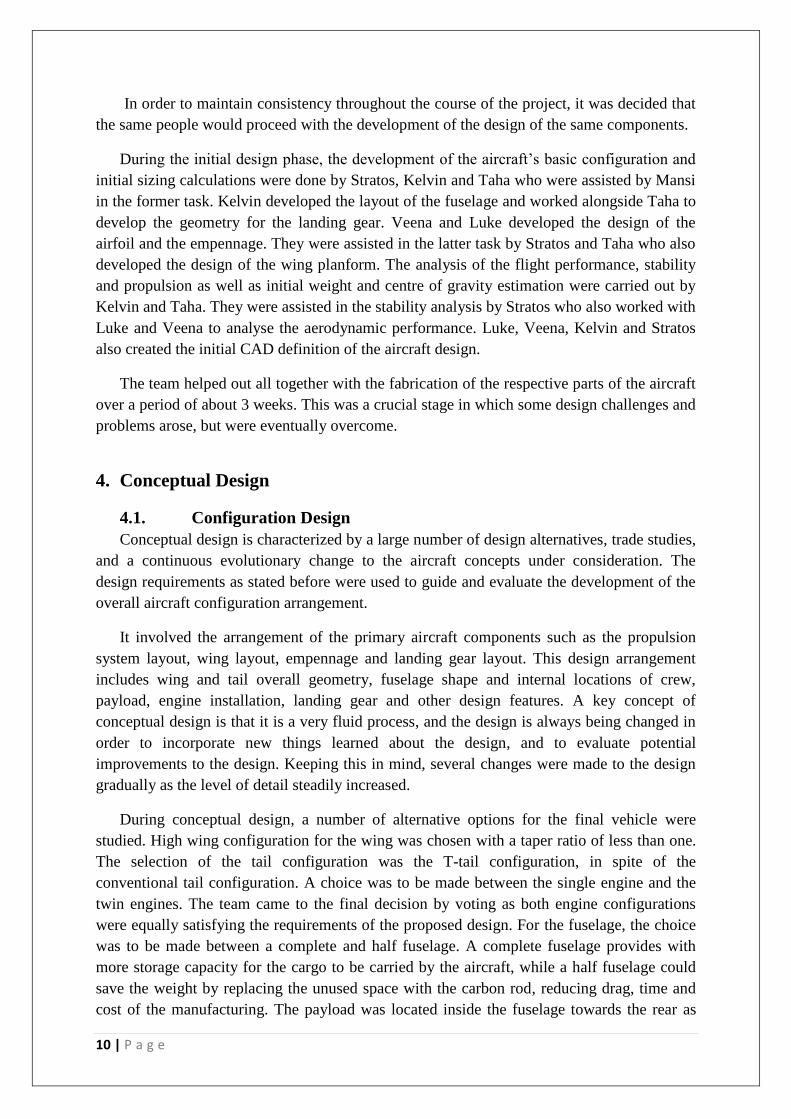
4. Conceptual Design
4.1. Configuration Design
Conceptual design is characterized by a large number of design alternatives, trade studies,
and a continuous evolutionary change to the aircraft concepts under consideration. The
design requirements as stated before were used to guide and evaluate the development of the
overall aircraft configuration arrangement.
It involved the arrangement of the primary aircraft components such as the propulsion
system layout, wing layout, empennage and landing gear layout. This design arrangement
includes wing and tail overall geometry, fuselage shape and internal locations of crew,
payload, engine installation, landing gear and other design features. A key concept of
conceptual design is that it is a very fluid process, and the design is always being changed in
order to incorporate new things learned about the design, and to evaluate potential
improvements to the design. Keeping this in mind, several changes were made to the design
gradually as the level of detail steadily increased.
During conceptual design, a number of alternative options for the final vehicle were
studied. High wing configuration for the wing was chosen with a taper ratio of less than one.
The selection of the tail configuration was the T-tail configuration, in spite of the
conventional tail configuration. A choice was to be made between the single engine and the
twin engines. The team came to the final decision by voting as both engine configurations
were equally satisfying the requirements of the proposed design. For the fuselage, the choice
was to be made between a complete and half fuselage. A complete fuselage provides with
more storage capacity for the cargo to be carried by the aircraft, while a half fuselage could
save the weight by replacing the unused space with the carbon rod, reducing drag, time and
cost of the manufacturing. The payload was located inside the fuselage towards the rear as
11 | P a g e
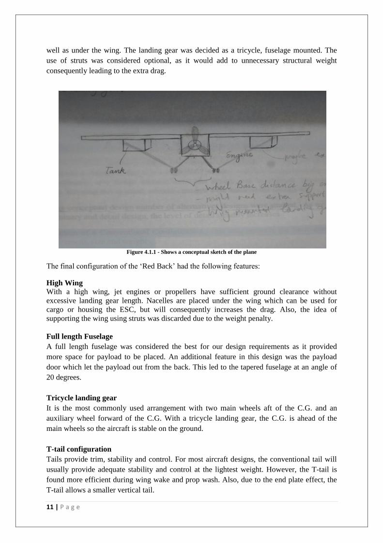
well as under the wing. The landing gear was decided as a tricycle, fuselage mounted. The
use of struts was considered optional, as it would add to unnecessary structural weight
consequently leading to the extra drag.
Figure 4.1.1 - Shows a conceptual sketch of the plane
The final configuration of the ‘Red Back’ had the following features:
High Wing
With a high wing, jet engines or propellers have sufficient ground clearance without
excessive landing gear length. Nacelles are placed under the wing which can be used for
cargo or housing the ESC, but will consequently increases the drag. Also, the idea of
supporting the wing using struts was discarded due to the weight penalty.
Full length Fuselage
A full length fuselage was considered the best for our design requirements as it provided
more space for payload to be placed. An additional feature in this design was the payload
door which let the payload out from the back. This led to the tapered fuselage at an angle of
20 degrees.
Tricycle landing gear
It is the most commonly used arrangement with two main wheels aft of the C.G. and an
auxiliary wheel forward of the C.G. With a tricycle landing gear, the C.G. is ahead of the
main wheels so the aircraft is stable on the ground.
T-tail configuration
Tails provide trim, stability and control. For most aircraft designs, the conventional tail will
usually provide adequate stability and control at the lightest weight. However, the T-tail is
found more efficient during wing wake and prop wash. Also, due to the end plate effect, the
T-tail allows a smaller vertical tail.
12 | P a g e
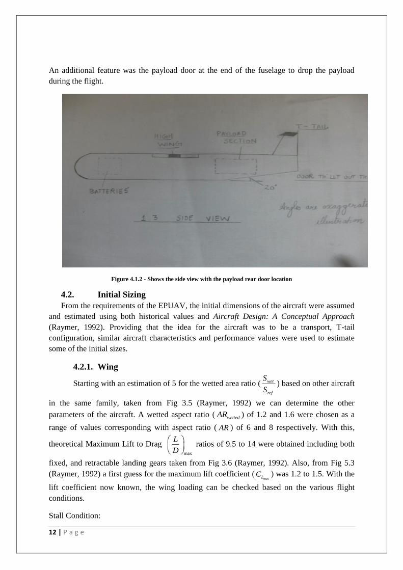
An additional feature was the payload door at the end of the fuselage to drop the payload
during the flight.
Figure 4.1.2 - Shows the side view with the payload rear door location
4.2. Initial Sizing
From the requirements of the EPUAV, the initial dimensions of the aircraft were assumed
and estimated using both historical values and Aircraft Design: A Conceptual Approach
(Raymer, 1992). Providing that the idea for the aircraft was to be a transport, T-tail
configuration, similar aircraft characteristics and performance values were used to estimate
some of the initial sizes.
4.2.1. Wing
Starting with an estimation of 5 for the wetted area ratio ( wet
ref
S
S) based on other aircraft
in the same family, taken from Fig 3.5 (Raymer, 1992) we can determine the other
parameters of the aircraft. A wetted aspect ratio ( wettedAR ) of 1.2 and 1.6 were chosen as a
range of values corresponding with aspect ratio ( AR ) of 6 and 8 respectively. With this,
theoretical Maximum Lift to Drag max
L
D
ratios of 9.5 to 14 were obtained including both
fixed, and retractable landing gears taken from Fig 3.6 (Raymer, 1992). Also, from Fig 5.3
(Raymer, 1992) a first guess for the maximum lift coefficient (maxLC ) was 1.2 to 1.5. With the
lift coefficient now known, the wing loading can be checked based on the various flight
conditions.
Stall Condition:
13 | P a g e
max
21
2stall L
stall
WV C
S
From the stall equations we obtain a wing loading between 18 and 23 kg/m2.
Cruise Condition:
oD
cruise
Wq ARC e
S
From the Cruise requirements, we obtain a wing loading between 250 and 300 kg/m2. This
value is quite high with the requirements for stall being the lowest, and the key criteria to
satisfy.
After having determined a final wing loading of about 20 kg/m2, we compared this to the 4.6
kg/m2 from historical data and found that this was relatively high. We then went back and a
gain re-calculated the above conditions, given the wing loading from historical data. The new
results led to much more reasonable values for the chord and span requirements for the wing.
With a TOW = 2.5kg: AR = 6 c = 0.33m b = 1.96m
AR = 8 c = 0.26m b = 2.08m
Estimations were also considered for wing loadings of 10 kg/m2 given below:
With a TOW = 4kg: AR = 6 c = 0.258m b = 1.64m
AR = 8 c = 0.22m b = 1.81m
From the above calculations, a compromise was made in order to satisfy the requirements
first provided to this project. With this into consideration the final basic specifications of the
aircraft are:
TOW = 5kg refS = 0.5m
2 c = 0.288m b = 1.74m
Allowing for some changes and deviance in the calculations the final numbers were decided
as:
TOW = 5kg refS = 0.54m
2 c = 0.3m b = 1.8m
Table 1 below shows the final sizing of the wing. C
changes to the initial estimations had been made as a result of the stability analysis. The
changes included removing the taper which was evident in the initial conceptual design
sketches which were intended to be part of the aircraft to reduce the weight at the wing tips.
14 | P a g e
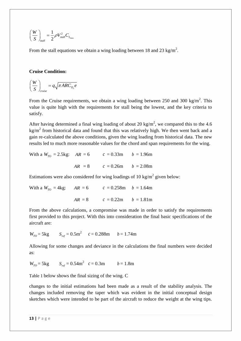
However, it was found that the added reference area was needed in order to maintain a19stallV ms . Also, the wing chord was increased to 0.35m and span to 2.1m.
Wing Chord root, rootc 0.35
Wing Chord root, tipc 0.35
Wing Span, b 2.1
Wing Area, refS 0.735
Wetted Area, wetS 1.498
Aspect Ratio, AR 6.000
Taper Ratio, 1
Sweep Angle, LE 0
Sweep Angle, 4
c 0
Thickness ratio, t
c
0.1178
MAC, c 0.35
Table 1 - Final sizing for the wing section (m)
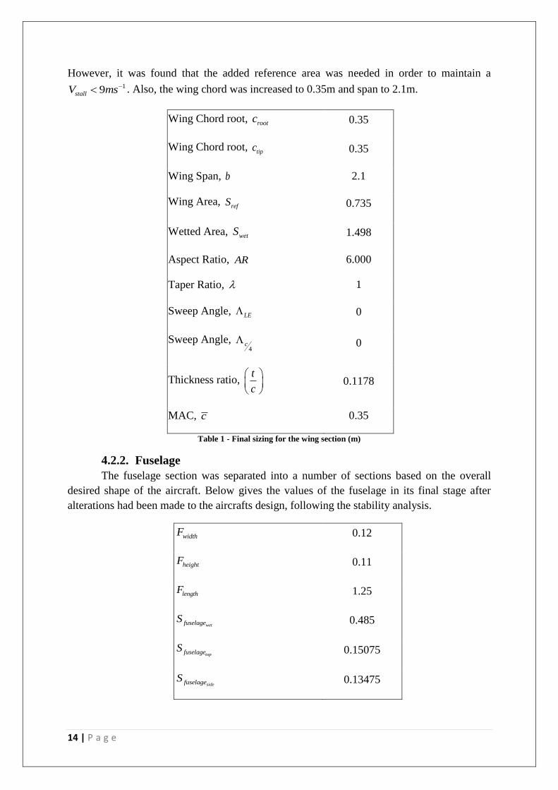
4.2.2. Fuselage
The fuselage section was separated into a number of sections based on the overall
desired shape of the aircraft. Below gives the values of the fuselage in its final stage after
alterations had been made to the aircrafts design, following the stability analysis.
widthF 0.12
heightF 0.11
lengthF 1.25
wetfuselageS 0.485
topfuselageS 0.15075
sidefuselageS 0.13475

15 | P a g e
noseF 0.15
doorF 0.25
Table 2 - Final sizing for the fuselage (m)
4.2.3. Empennage
The Empennage was designed to coincide with the desire to have a T-Tail
configuration. As such the Vertical Tail would be tapered, while the Horizontal Tail would
remain rectangular in shape. Some changes to the sizing of the empennage were made when
problems arose with the weights and balancing of the aircraft. The calculations for the
empennage were base on those equations and relations outlined in ‘Aircraft Design – A
Conceptual Approach’ (Raymer, 1992).
Tail Volume Coefficient
The primary purpose of the tail is to counter the moments produced by the wing. Therefore
the tail size must in some way be related to the size of the wing. The force due to tail lift is
proportional to the tail area. Thus, the tail effectiveness is proportional to the tail area
multiplied by the moment arm. Tail volume coefficients can be calculated through the
following equations.
In order to calculate the tail size, the moment arm must first be estimated. This can be
approximated by a percentage of the fuselage length. For an aircraft with the engines
mounted on the wings, such as ours, the tail arm is about 50-55% of the fuselage length. For
the T-Tail configuration, the vertical tail volume coefficient can be reduced by approximately
5% due to the end plate effect. The horizontal tail volume coefficient can also be reduced by
approximately 5% due to the clean airflow over the horizontal tail.
Vertical Tail
Vertical Tail Coefficient: vt vtvt
L Sc
bS (Equation 6.26)
Vert tail chord, basevertc 0.37
Vert tail chord, topvertc 0.28
Vert tail height, verth 0.35
Vert tail area, vtS 0.114
Vert tail moment arm, vtL 0.5322
Vert tail volume coeff, vtc 0.039

16 | P a g e
Vert tail wetted, wetvertS 0.232
Vert tail taper ratio, vert 0.757
MAC, vertc 0.327
Table 3 - Final Sizing for the Vertical Tail (m)
Raymer (1992) suggests 0.04vtc for a homebuilt aircraft. The aircraft that we designed is
more of a transport aircraft, however in Table 6.4 (Raymer, 1992), these types of aircraft
would normally have a 0.07 0.08vtc . This would mean that the tail would become much
larger than would be possible. The final configuration was based on the vtc as well as by eye.
We looked at it and also conferred with Professor Yu and settled on the above configuration
in Table 3.
Horizontal Tail
Horizontal Tail Coefficient: ht horht
L Sc
cS (Equation 6.27)
Hori tail chord, horc 0.28
Hori tail span, horb 0.84
Hori tail area, horS 0.235
Hori tail moment arm htL 0.5675
Hori tail volume coeff, htc 0.519
Hori tail wetted, wethorS 0.479
Table 4 – Final Sizing for the Horizontal Tail (m)
Raymer (1992) suggests that the htc = 0.5 for a homebuilt aircraft. As stated above, for
transport aircraft the htc = 1.00. This again would mean a much larger tail that was designed.
4.3. Fuselage Layout
The main objective of the aircraft was to carry a large amount of weight and drop some
payload, like a transport aircraft (C-5 Galaxy and C-17 Globemaster). Apart from carrying
payload, the fuselage would also be carrying parts of the control system and batteries to
power the aircraft. In order to fulfil this requirement the fuselage needs to be strong, stiff and
have sufficient space inside to the items mentioned above as well as still providing some
room for access.
17 | P a g e
The team went through various designs such as a square fuselage, circular and
semicircular fuselages. The advantages and disadvantages of various shapes of the fuselage
are as follows:
Square Fuselage: Most of the aircrafts built in the university had this shape. As the team
members wanted to face some challenge, it was decided that this shape was simple and easy
to construct. Some of the advantages of square fuselage are easy to construct large payload
space and almost zero torsion. Disadvantages include high drag due to sharp edges, as well as
not being appealing to the eye.
Circular Fuselage: The circular fuselage would be difficult to construct. The advantages
of circular fuselage are less drag and aerodynamic shape. The disadvantages include less
payload space and high torsion.
From the advantages and disadvantages of the above mentioned designs, we can see that
to maximise the payload space we require square fuselage, but to improve aerodynamic
properties we require circular fuselage, so it was decided to use both the designs together.
The fuselage has flat sides and circular top and bottom. This design has large room for the
payload, has good aerodynamics properties and it looks good.
The main idea was to utilize all the space available in the fuselage and minimise the
weight. The nose section of the fuselage was made out of polystyrene foam as it was not
carrying any load apart from keeping the shape, and providing good aerodynamic properties.
It was decided that immediately after the nose, the front or nose landing gear was to be placed
along with the steering servo for the nose landing gear. The batteries were placed in front of
the wing to balance the moment arm due to horizontal tail.
The aircraft utilizes a high wing configuration for stability. The payload was divided into
two section, mid-section and rear section. The mid-section door was located under the wing.
The control system section was also under the wing and after the mid-section payload door.
Immediately behind the mid-section is the control system section, followed by the rear
payload area. The rear section of the fuselage is tapered to replicate a cargo airplane. The T-
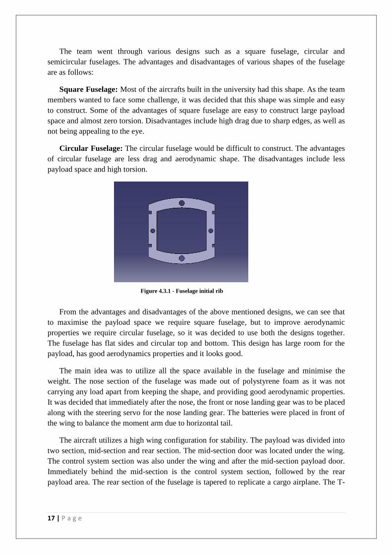
Figure 4.3.1 - Fuselage initial rib
18 | P a g e
tail is mounted on top of the rear section of the fuselage. The whole fuselage is designed in
such a way that it is easy to assemble, as well as easy to dismantle.
4.4. Airfoil Design
The selection of the airfoil was based on factors such as the airfoil drag during cruise,
stall and pitching moment characteristics and the thickness available for the structure as well
as ease of manufacture.
Airfoil characteristics are strongly affected by Reynolds number ( Re ). The Re number
influences whether the flow will be laminar or turbulent or whether the flow separation will
occur. Maximum camber is an important feature, as it allows the flow to remain attached and
thus increases the lift and reduces drag. It also increases the lift by increasing the circulation
of the airflow. The thickness ratio has a direct effect on drag, maximum lift and structural
weight. The drag increases as the thickness is increased due to increased separation and
should be in the range of twelve to sixteen percent.
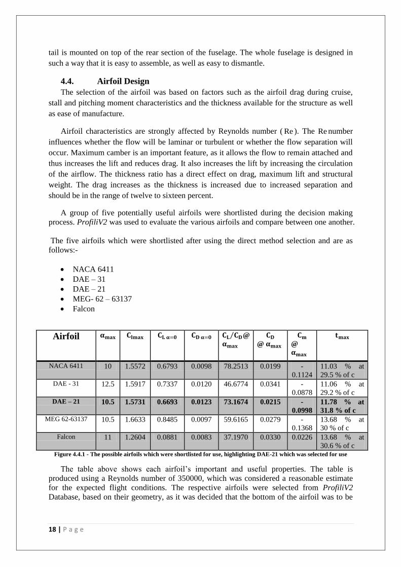
A group of five potentially useful airfoils were shortlisted during the decision making
process. ProfiliV2 was used to evaluate the various airfoils and compare between one another.
The five airfoils which were shortlisted after using the direct method selection and are as
follows:-
NACA 6411
DAE – 31
DAE – 21
MEG- 62 – 63137
Falcon
Airfoil 𝛂𝐦𝐚𝐱 𝐂𝐥𝐦𝐚𝐱 𝐂𝐋 𝛂=𝟎 𝐂𝐃 𝛂=𝟎 𝐂𝐋 𝐂𝐃 @
𝛂𝐦𝐚𝐱
𝐂𝐃
@ 𝛂𝐦𝐚𝐱
𝐂𝐦
@
𝛂𝐦𝐚𝐱
𝐭𝐦𝐚𝐱
NACA 6411 10 1.5572 0.6793 0.0098 78.2513 0.0199 -
0.1124
11.03 % at
29.5 % of c
DAE - 31 12.5 1.5917 0.7337 0.0120 46.6774 0.0341 -
0.0878
11.06 % at
29.2 % of c
DAE – 21 10.5 1.5731 0.6693 0.0123 73.1674 0.0215 -
0.0998
11.78 % at
31.8 % of c
MEG 62-63137 10.5 1.6633 0.8485 0.0097 59.6165 0.0279 -
0.1368
13.68 % at
30 % of c
Falcon 11 1.2604 0.0881 0.0083 37.1970 0.0330 0.0226 13.68 % at
30.6 % of c Figure 4.4.1 - The possible airfoils which were shortlisted for use, highlighting DAE-21 which was selected for use
The table above shows each airfoil’s important and useful properties. The table is
produced using a Reynolds number of 350000, which was considered a reasonable estimate
for the expected flight conditions. The respective airfoils were selected from ProfiliV2
Database, based on their geometry, as it was decided that the bottom of the airfoil was to be
19 | P a g e
as flat as possible in order to make fabrication of the wing easier. Also the airfoils were
chosen based on the high maximum lift coefficient requirements predicted for the aircraft.
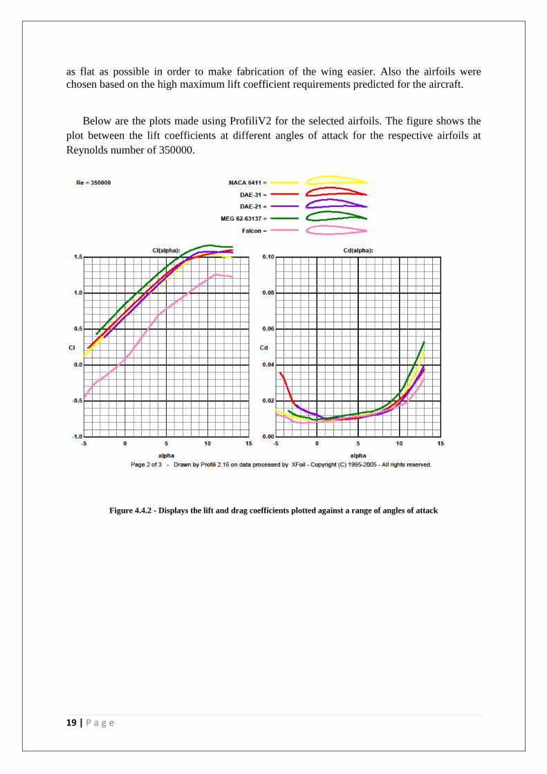
Below are the plots made using ProfiliV2 for the selected airfoils. The figure shows the
plot between the lift coefficients at different angles of attack for the respective airfoils at
Reynolds number of 350000.
Figure 4.4.2 - Displays the lift and drag coefficients plotted against a range of angles of attack
20 | P a g e
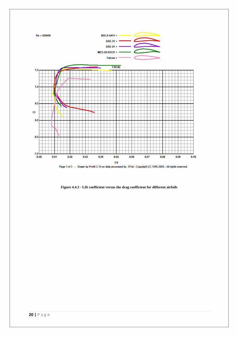
Figure 4.4.3 - Lift coefficient versus the drag coefficient for different airfoils

21 | P a g e
Figure 4.4.4 - Displays the lift to drag ratio and moment coefficients plotted against a range of angles of attack
These graphs provided the team with a better understanding of the abilities and limits of
the airfoils. An airfoil with a maximum lift coefficient of greater than 1.4 at a maximum
angle of attack of 10.5 degrees was seen appropriate by the team for the wing. The final
selection of the airfoil was the DAE- 21 for the wing, with the flattest bottom surface and also
on the basis of maximum camber, thickness and lift coefficient produced.
The value of the moment coefficient of the airfoils proved to be a deciding factor in
choosing a decent airfoil. A smaller value in regards to the moment coefficient is desirable as
it means the nose down moment produced by the wing would be reduced making it more
stable. If it is unduly large, there may be a significant trim drag penalty. When comparing to
the values attained from graphs for the selected airfoils, it was clearly seen that DAE-21
satisfied the requirements of having the semi-flat surface, along with a moderate negative
pitching moment, and producing high lift-to-drag ratio.
4.5. Wing Design
The wing was selected to be rectangular but tapered in order to reduce weight. Out of the
primary plan form parameters, taper ratio and aspect ratio were calculated. Other parameters
such as the dihedral and twist were not required for the design.

22 | P a g e
An elliptical wing plan form was disregarded as it would have been more difficult to
manufacture. Taper affects the distribution of lift along the span of the wing. The tapered
rectangular wing was considered as the tip chords becomes shorter, alleviating the
undesirable effects of the constant- chord rectangular wing.
Figure 4.5.1 - A top view of the final configuration
Figure 4.5.2 - CAD definition of the final configuration
However, the design was changed to just rectangular plan form making the taper ratio 1 in
order to decrease the wing loading and meet the minimum stall speed requirements. Taper
would have helped us gain a better value for Oswald’s span efficient factor, e which would
reduce the drag due to lift. The positive effect gained by having a tapered wing was not

23 | P a g e
deemed large enough by the design team to warrant the extra time and effort required to
design and build a tapered wing.
4.6. Empennage Design
Several design concepts for the empennage were analysed, however the particular tail
chosen for the aircraft was an unswept T-Tail configuration. Some of the other design
concepts considered involved a standard configuration that involved a lower mounted
horizontal stabiliser. The structure for the T-Tail was to be constructed from airfoils rather
than a standard flat plate. Although this proved to be more work than originally anticipated,
the group decided that it would prove to be the most aerodynamic and thus beneficial to the
aircraft flight characteristics.
The T-Tail is usually inherently heavier than the standard tail configuration because the
vertical tail must be strengthened to support the horizontal tail. Some of the chosen
advantages for the T-Tail configuration are that due to the end-plate effects, the T-Tail allows
for a smaller vertical tail. The high horizontal tail also means that the horizontal tail is clear
of the wing wake and prop wash, thus increasing its efficiency and allowing for a reduced
size. This also reduces buffet on the horizontal tail from unsteady airflow over the horizontal
tail. This reduction in buffet means that the structural fatigue will be less this is due to the
laminar flow which provides a uniform lift force rather than an uneven distribution.
The location of the tail system with respect to the wing is critical to the stall
characteristics of the aircraft. If the tail system enters the wing wake during the stall, control
will be lost and severe pitch up may be encountered. Due to the low required stall speed, it is
crucial that control of the aircraft will maintain during the event of stall. Therefore, the
location of the tail behind the wing was carefully calculated so suitable moments were met.
The final T-Tail configuration utilised two carbon rods, which ran through the vertical tail
and attached to the horizontal tail. This design will further be discussed.
4.7. Landing Gear
Due to the configuration of the aircraft, a tricycle landing gear was used with a single
nose wheel and two wheels somewhere along the length of the fuselage. In the initial design
phase, the main landing gear of the aircraft was envisaged as straight stiff carbon fibre rods
attached directly to the sides of the fuselage, descending vertically. Alternatively, these rods
could have springs attached to them to provide suspension and absorb the load during landing.
4.8. Analysis of Propulsion
A propulsion test was carried out by the two teams to ensure that the motors provided
would be powerful enough for the aircraft. As per the design specifications the ‘#2006’ type
24 | P a g e
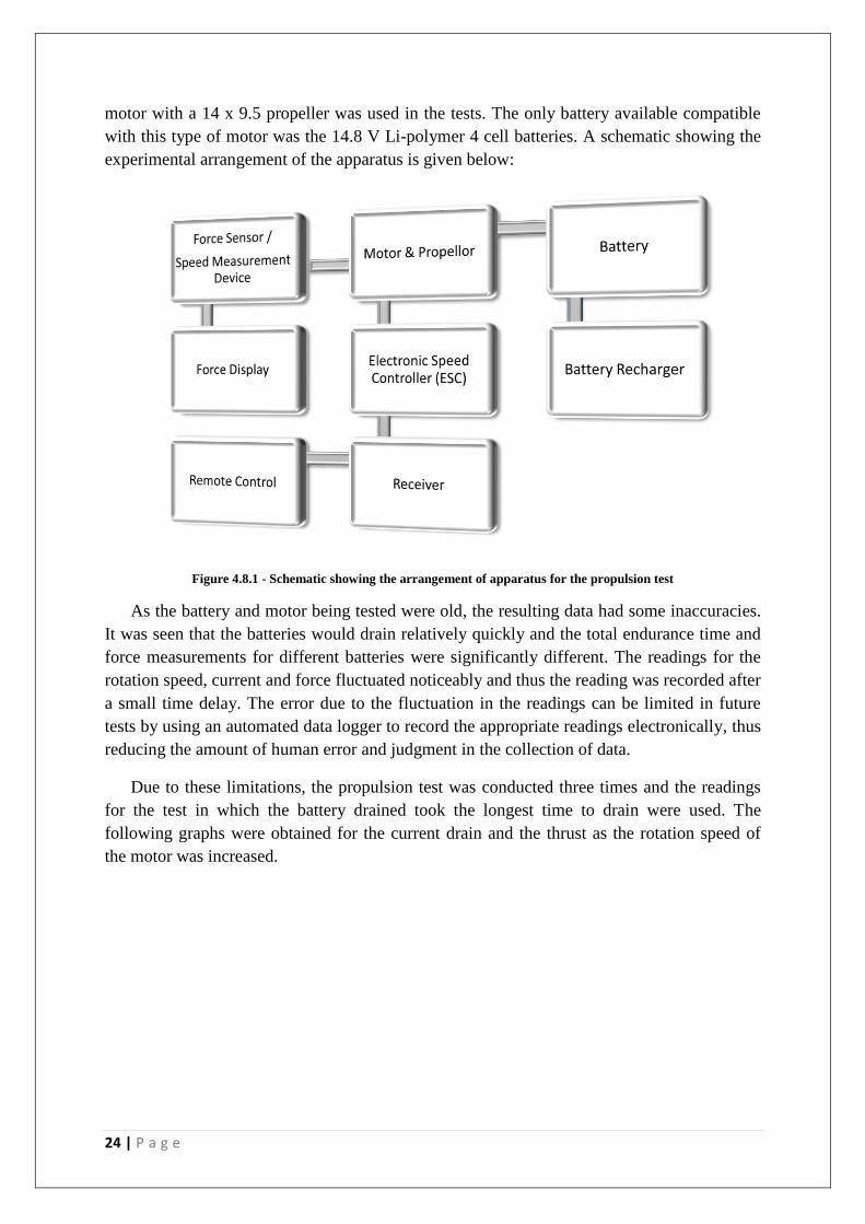
motor with a 14 x 9.5 propeller was used in the tests. The only battery available compatible
with this type of motor was the 14.8 V Li-polymer 4 cell batteries. A schematic showing the
experimental arrangement of the apparatus is given below:
Figure 4.8.1 - Schematic showing the arrangement of apparatus for the propulsion test
As the battery and motor being tested were old, the resulting data had some inaccuracies.
It was seen that the batteries would drain relatively quickly and the total endurance time and
force measurements for different batteries were significantly different. The readings for the
rotation speed, current and force fluctuated noticeably and thus the reading was recorded after
a small time delay. The error due to the fluctuation in the readings can be limited in future
tests by using an automated data logger to record the appropriate readings electronically, thus
reducing the amount of human error and judgment in the collection of data.
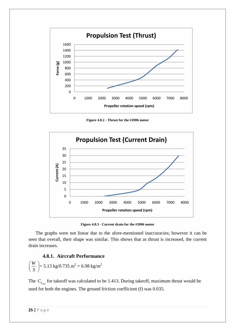
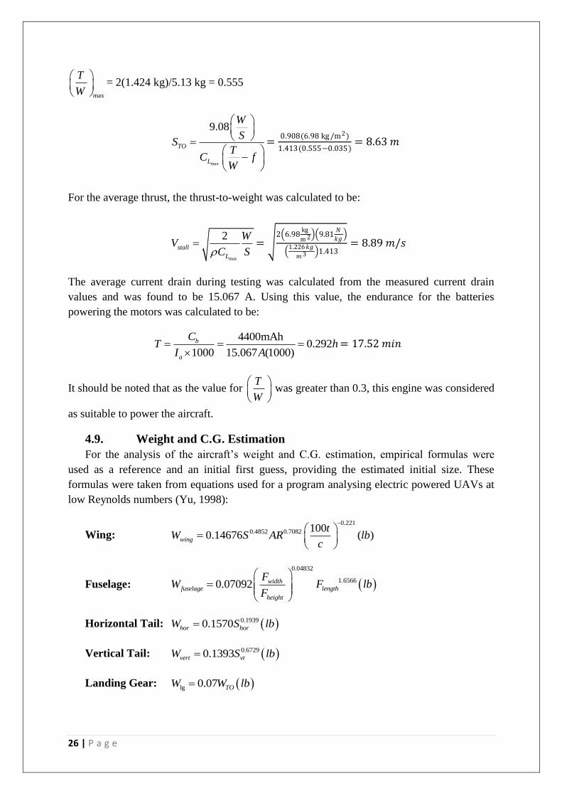
Due to these limitations, the propulsion test was conducted three times and the readings
for the test in which the battery drained took the longest time to drain were used. The
following graphs were obtained for the current drain and the thrust as the rotation speed of
the motor was increased.
25 | P a g e
Figure 4.8.2 - Thrust for the #2006 motor
Figure 4.8.3 - Current drain for the #2006 motor
The graphs were not linear due to the afore-mentioned inaccuracies; however it can be
seen that overall, their shape was similar. This shows that as thrust is increased, the current
drain increases.
4.8.1. Aircraft Performance
W
S
= 5.13 kg/0.735 m2 = 6.98 kg/m
2
The maxLC for takeoff was calculated to be 1.413. During takeoff, maximum thrust would be
used for both the engines. The ground friction coefficient (f) was 0.035.
0
200
400
600
800
1000
1200
1400
1600
0 1000 2000 3000 4000 5000 6000 7000 8000
Forc
e (
g)
Propeller rotation speed (rpm)
Propulsion Test (Thrust)
0
5
10
15
20
25
30
35
0 1000 2000 3000 4000 5000 6000 7000 8000
Cu
rre
nt
(A)
Propeller rotation speed (rpm)
Propulsion Test (Current Drain)
26 | P a g e
max
T
W
= 2(1.424 kg)/5.13 kg = 0.555
max
9.08
TO
L
W
SS
TC f
W
=0.908(6.98 kg /m2)
1.413(0.555−0.035)= 8.63 𝑚
For the average thrust, the thrust-to-weight was calculated to be:
max
2stall
L
WV
C S =
2 6.98kg
m 2 9.81𝑁
𝑘𝑔
1.226𝑘𝑔
𝑚3 1.413= 8.89 𝑚/𝑠
The average current drain during testing was calculated from the measured current drain
values and was found to be 15.067 A. Using this value, the endurance for the batteries
powering the motors was calculated to be:
4400mAh0.292
1000 15.067 (1000)
b
a
CT h
I A
= 17.52 𝑚𝑖𝑛
It should be noted that as the value for T
W
was greater than 0.3, this engine was considered
as suitable to power the aircraft.
4.9. Weight and C.G. Estimation
For the analysis of the aircraft’s weight and C.G. estimation, empirical formulas were
used as a reference and an initial first guess, providing the estimated initial size. These
formulas were taken from equations used for a program analysing electric powered UAVs at
low Reynolds numbers (Yu, 1998):
Wing:
0.221
0.4852 0.7082 1000.14676 ( )wing
tW S AR lb
c
Fuselage:
0.04832
1.65660.07092 widthfuselage length
height
FW F lb
F
Horizontal Tail: 0.19390.1570hor horW S lb
Vertical Tail: 0.67290.1393vert vtW S lb
Landing Gear: lg 0.07 TOW W lb
27 | P a g e
With these weights we obtained our basic aircraft weight, by adding a scaling factor to
account for any errors in the empirical formulas. The equations were developed as an average
of historical data taken from many different model aircraft, so, to ensure some leniency in the
weight estimation, the scaling factor of 1.2 was used. We then added to this the weights of
additional components including the engines, batteries, wiring, adhesive and the covering
skin. All together, they would combine to give us an initial guess as to the aircrafts weight
without any additional payload requirements. Furthermore, given the complex nature of the
estimation and tedious work of re-calculating numbers when changes are made, the entire
weight and analysis of the aircraft was developed on an Excel spreadsheet. This was a very
simple and extremely effective method of analysing the aircraft quickly and accurately for
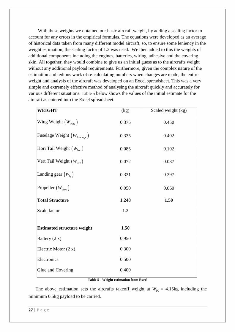
various different situations. Table 5 below shows the values of the initial estimate for the
aircraft as entered into the Excel spreadsheet.
WEIGHT (kg) Scaled weight (kg)
Wing Weight wingW 0.375 0.450
Fuselage Weight fuselageW 0.335 0.402
Hori Tail Weight horW 0.085 0.102
Vert Tail Weight vertW 0.072 0.087
Landing gear lgW 0.331 0.397
Propeller propW 0.050 0.060
Total Structure 1.248 1.50
Scale factor 1.2
Estimated structure weight 1.50
Battery (2 x) 0.950
Electric Motor (2 x) 0.300
Electronics 0.500
Glue and Covering 0.400
Table 5 - Weight estimation form Excel
The above estimation sets the aircrafts takeoff weight at TOW = 4.15kg including the
minimum 0.5kg payload to be carried.
28 | P a g e
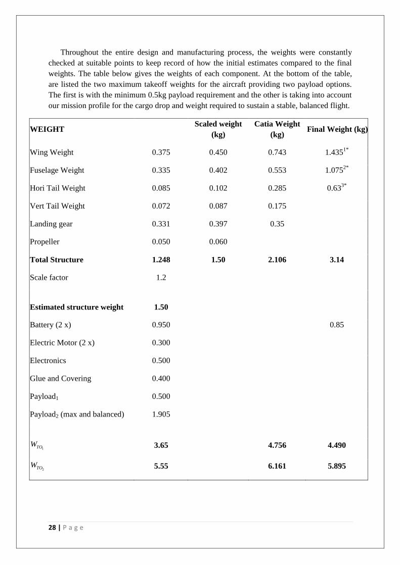
Throughout the entire design and manufacturing process, the weights were constantly
checked at suitable points to keep record of how the initial estimates compared to the final
weights. The table below gives the weights of each component. At the bottom of the table,
are listed the two maximum takeoff weights for the aircraft providing two payload options.
The first is with the minimum 0.5kg payload requirement and the other is taking into account
our mission profile for the cargo drop and weight required to sustain a stable, balanced flight.
WEIGHT
Scaled weight
(kg)
Catia Weight
(kg) Final Weight (kg)
Wing Weight 0.375 0.450 0.743 1.4351*
Fuselage Weight 0.335 0.402 0.553 1.0752*
Hori Tail Weight 0.085 0.102 0.285 0.633*
Vert Tail Weight 0.072 0.087 0.175
Landing gear 0.331 0.397 0.35
Propeller 0.050 0.060
Total Structure 1.248 1.50 2.106 3.14
Scale factor 1.2
Estimated structure weight 1.50
Battery (2 x) 0.950
0.85
Electric Motor (2 x) 0.300
Electronics 0.500
Glue and Covering 0.400
Payload1 0.500
Payload2 (max and balanced) 1.905
1TOW 3.65
4.756 4.490
2TOW 5.55
6.161 5.895
29 | P a g e
1 The weight of the wing also includes the weights of the ESCs and the motors.
2 The weight of the fuselage also includes the weight of the landing gear.
3 The weight entered as the ‘Horizontal Tail’ includes the ‘Vertical Tail’ in this case as they were weighed as one piece.
* The weights include all the wires and electronic equipment such as servos, as well as the adhesives and skin coverings.
Table 6 - Final Table of Weights
As can be seen in the table, the weights as estimated using the empirical formula have
given us a much lighter prediction for the overall aircraft’s weight. The ‘CATIA’ weights
seem to be a bit more reasonable as they still do not include the weights of additional items
like the motors, electrical wiring, or adhesive. Overall however, it can be seen that our
predictions through various methods had resulted in a heavier aircraft than what we had
manufactured. This seems like it is due to the estimates of the covering, adhesive, and
electronic material being a little higher than they actually are, although, the actual final
weight of the aircraft is similar to that predicted using the CATIA weights and the additional
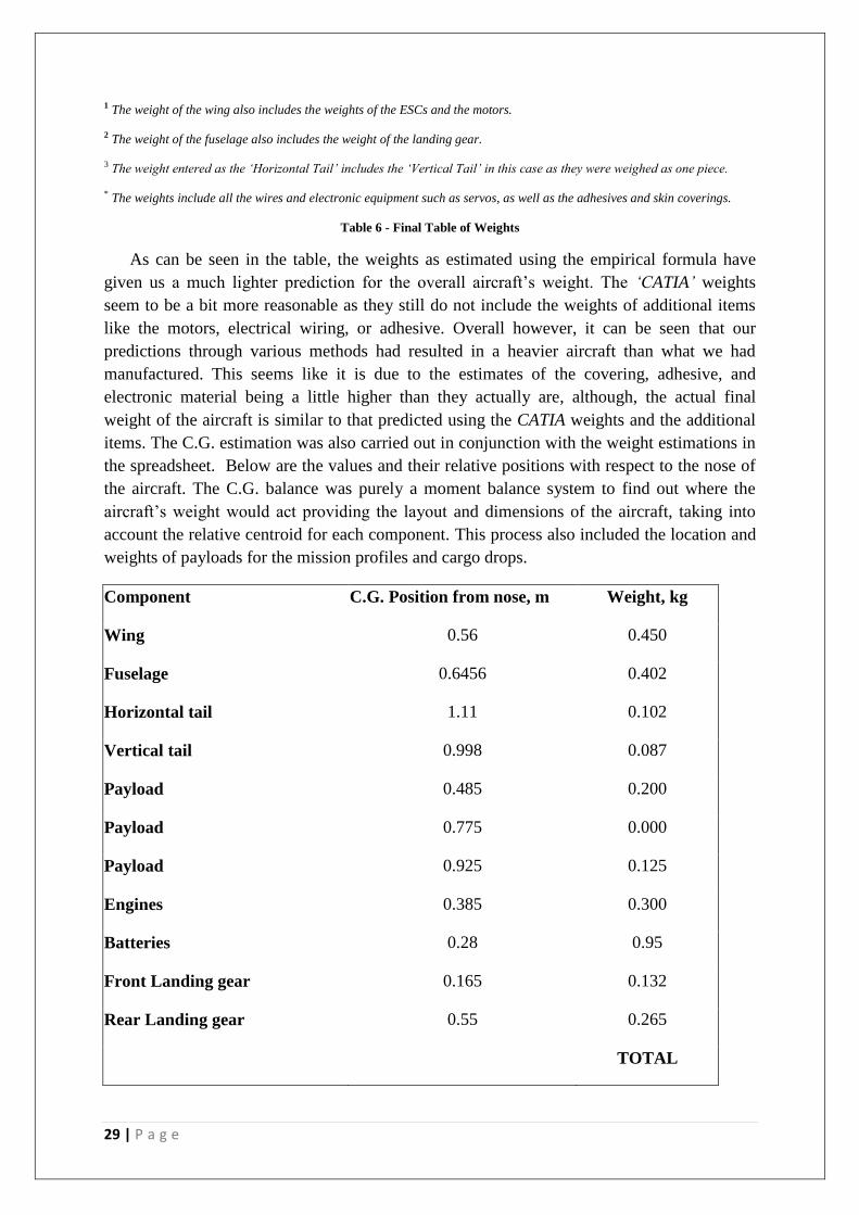
items. The C.G. estimation was also carried out in conjunction with the weight estimations in
the spreadsheet. Below are the values and their relative positions with respect to the nose of
the aircraft. The C.G. balance was purely a moment balance system to find out where the
aircraft’s weight would act providing the layout and dimensions of the aircraft, taking into
account the relative centroid for each component. This process also included the location and
weights of payloads for the mission profiles and cargo drops.
Component C.G. Position from nose, m Weight, kg
Wing 0.56 0.450
Fuselage 0.6456 0.402
Horizontal tail 1.11 0.102
Vertical tail 0.998 0.087
Payload 0.485 0.200
Payload 0.775 0.000
Payload 0.925 0.125
Engines 0.385 0.300
Batteries 0.28 0.95
Front Landing gear 0.165 0.132
Rear Landing gear 0.55 0.265
TOTAL
30 | P a g e
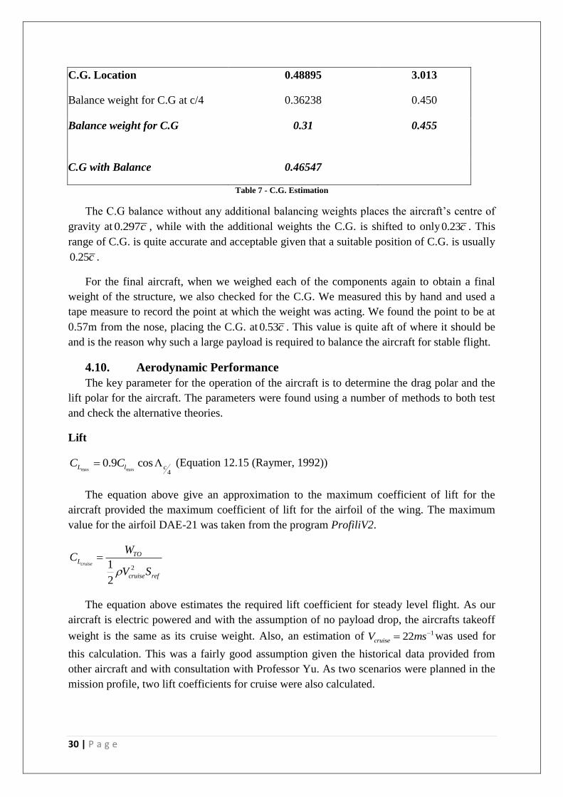
C.G. Location 0.48895 3.013
Balance weight for C.G at c/4 0.36238 0.450
Balance weight for C.G 0.31 0.455
C.G with Balance 0.46547
Table 7 - C.G. Estimation
The C.G balance without any additional balancing weights places the aircraft’s centre of
gravity at 0.297c , while with the additional weights the C.G. is shifted to only0.23c . This
range of C.G. is quite accurate and acceptable given that a suitable position of C.G. is usually
0.25c .
For the final aircraft, when we weighed each of the components again to obtain a final
weight of the structure, we also checked for the C.G. We measured this by hand and used a
tape measure to record the point at which the weight was acting. We found the point to be at
0.57m from the nose, placing the C.G. at 0.53c . This value is quite aft of where it should be
and is the reason why such a large payload is required to balance the aircraft for stable flight.
4.10. Aerodynamic Performance
The key parameter for the operation of the aircraft is to determine the drag polar and the
lift polar for the aircraft. The parameters were found using a number of methods to both test
and check the alternative theories.
Lift
max max4
0.9 cosL l cC C (Equation 12.15 (Raymer, 1992))
The equation above give an approximation to the maximum coefficient of lift for the
aircraft provided the maximum coefficient of lift for the airfoil of the wing. The maximum
value for the airfoil DAE-21 was taken from the program ProfiliV2.
21
2
cruise
TOL
cruise ref
WC
V S
The equation above estimates the required lift coefficient for steady level flight. As our
aircraft is electric powered and with the assumption of no payload drop, the aircrafts takeoff
weight is the same as its cruise weight. Also, an estimation of 122cruiseV ms was used for
this calculation. This was a fairly good assumption given the historical data provided from
other aircraft and with consultation with Professor Yu. As two scenarios were planned in the
mission profile, two lift coefficients for cruise were also calculated.
31 | P a g e
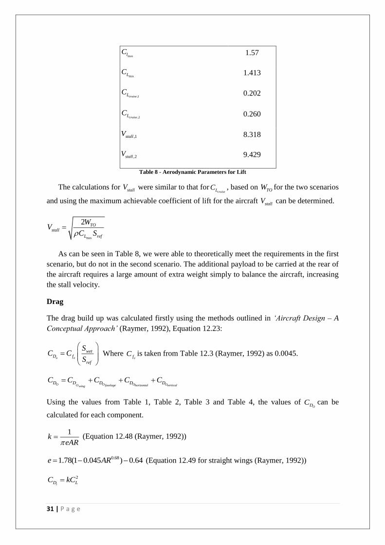
maxlC 1.57
maxLC 1.413
,1cruiseLC 0.202
,2cruiseLC 0.260
,1stallV 8.318
,2stallV 9.429
Table 8 - Aerodynamic Parameters for Lift
The calculations for stallV were similar to that forcruiseLC , based on TOW for the two scenarios
and using the maximum achievable coefficient of lift for the aircraft stallV can be determined.
max
2 TOstall
L ref
WV
C S
As can be seen in Table 8, we were able to theoretically meet the requirements in the first
scenario, but do not in the second scenario. The additional payload to be carried at the rear of
the aircraft requires a large amount of extra weight simply to balance the aircraft, increasing
the stall velocity.
Drag
The drag build up was calculated firstly using the methods outlined in ‘Aircraft Design – A
Conceptual Approach’ (Raymer, 1992), Equation 12.23:
o e
wetD f
ref
SC C
S
Where ef
C is taken from Table 12.3 (Raymer, 1992) as 0.0045.
O O O OO fuselage horizontal verticalwingD D D D DC C C C C
Using the values from Table 1, Table 2, Table 3 and Table 4, the values of ODC can be
calculated for each component.
1k
eAR (Equation 12.48 (Raymer, 1992))
0.681.78(1 0.045 ) 0.64e AR (Equation 12.49 for straight wings (Raymer, 1992))
2
iD LC kC
32 | P a g e
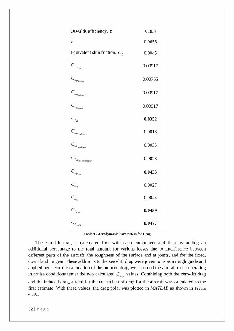
Oswalds efficiency, e 0.808
k 0.0656
Equivalent skin friction, ef
C 0.0045
OwingDC 0.00917
OfuselageDC 0.00765
OhorizontalDC 0.00917
OverticalDC 0.00917
ODC 0.0352
interferenceODC 0.0018
roughnessODC 0.0035
fixed landing gearODC 0.0028
TotalODC 0.0433
,1iDC 0.0027
,2iDC 0.0044
,1totalDC 0.0459
,2totalDC 0.0477
Table 9 - Aerodynamic Parameters for Drag
The zero-lift drag is calculated first with each component and then by adding an
additional percentage to the total amount for various losses due to interference between
different parts of the aircraft, the roughness of the surface and at joints, and for the fixed,
down landing gear. These additions to the zero-lift drag were given to us as a rough guide and
applied here. For the calculation of the induced drag, we assumed the aircraft to be operating
in cruise conditions under the two calculated cruiseLC values. Combining both the zero-lift drag
and the induced drag, a total for the coefficient of drag for the aircraft was calculated as the
first estimate. With these values, the drag polar was plotted in MATLAB as shown in Figure
4.10.1
33 | P a g e
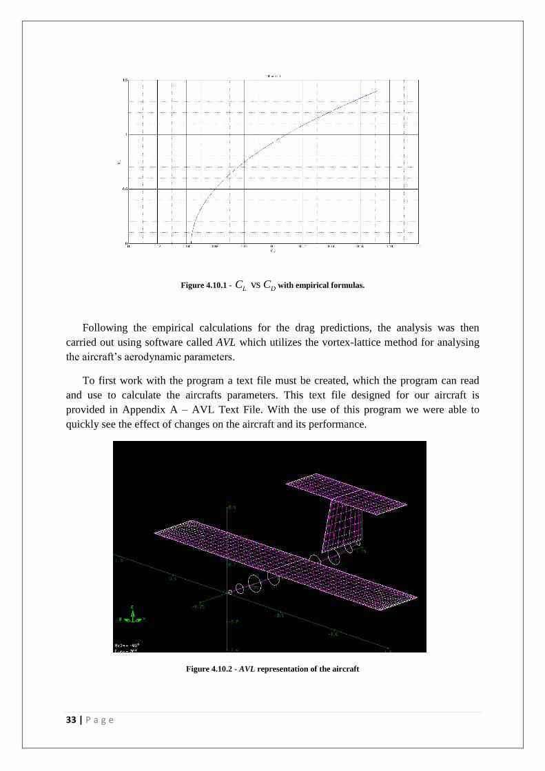
Figure 4.10.1 - vs L DC C with empirical formulas.
Following the empirical calculations for the drag predictions, the analysis was then
carried out using software called AVL which utilizes the vortex-lattice method for analysing
the aircraft’s aerodynamic parameters.
To first work with the program a text file must be created, which the program can read
and use to calculate the aircrafts parameters. This text file designed for our aircraft is
provided in Appendix A – AVL Text File. With the use of this program we were able to
quickly see the effect of changes on the aircraft and its performance.
Figure 4.10.2 - AVL representation of the aircraft
34 | P a g e
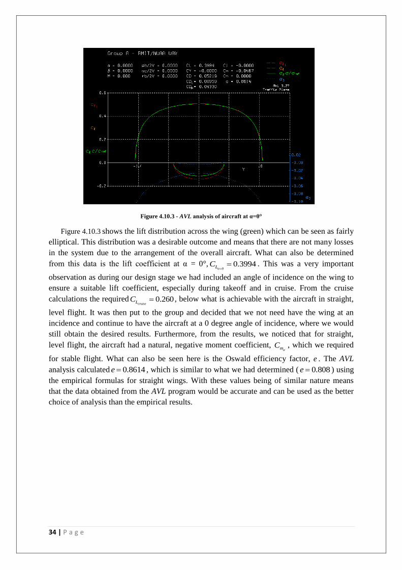
Figure 4.10.3 - AVL analysis of aircraft at α=0°
Figure 4.10.3 shows the lift distribution across the wing (green) which can be seen as fairly
elliptical. This distribution was a desirable outcome and means that there are not many losses
in the system due to the arrangement of the overall aircraft. What can also be determined
from this data is the lift coefficient at α = 0°,0
0.3994LC
. This was a very important
observation as during our design stage we had included an angle of incidence on the wing to
ensure a suitable lift coefficient, especially during takeoff and in cruise. From the cruise
calculations the required 0.260cruiseLC , below what is achievable with the aircraft in straight,
level flight. It was then put to the group and decided that we not need have the wing at an
incidence and continue to have the aircraft at a 0 degree angle of incidence, where we would
still obtain the desired results. Furthermore, from the results, we noticed that for straight,
level flight, the aircraft had a natural, negative moment coefficient, mC
, which we required
for stable flight. What can also be seen here is the Oswald efficiency factor, e . The AVL
analysis calculated 0.8614e , which is similar to what we had determined ( 0.808e ) using
the empirical formulas for straight wings. With these values being of similar nature means
that the data obtained from the AVL program would be accurate and can be used as the better
choice of analysis than the empirical results.
35 | P a g e
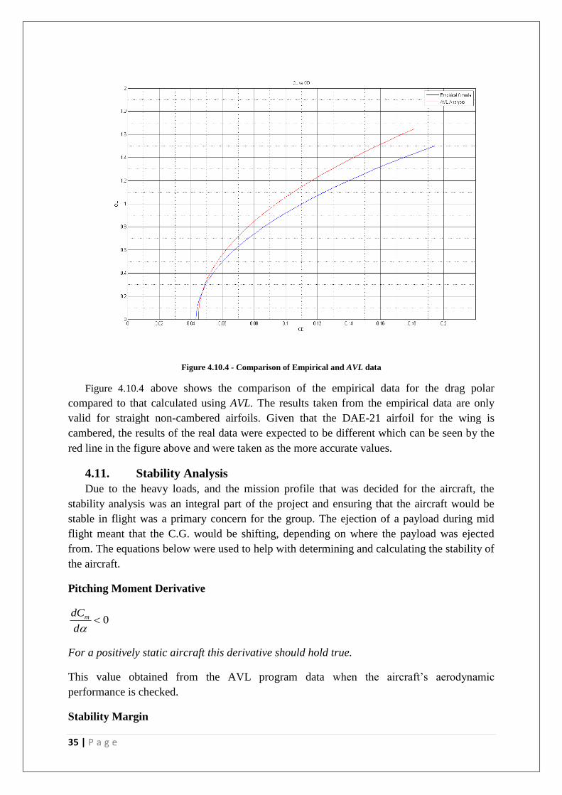
Figure 4.10.4 - Comparison of Empirical and AVL data
Figure 4.10.4 above shows the comparison of the empirical data for the drag polar
compared to that calculated using AVL. The results taken from the empirical data are only
valid for straight non-cambered airfoils. Given that the DAE-21 airfoil for the wing is
cambered, the results of the real data were expected to be different which can be seen by the
red line in the figure above and were taken as the more accurate values.
4.11. Stability Analysis
Due to the heavy loads, and the mission profile that was decided for the aircraft, the
stability analysis was an integral part of the project and ensuring that the aircraft would be
stable in flight was a primary concern for the group. The ejection of a payload during mid
flight meant that the C.G. would be shifting, depending on where the payload was ejected
from. The equations below were used to help with determining and calculating the stability of
the aircraft.
Pitching Moment Derivative
0mdC
d
For a positively static aircraft this derivative should hold true.
This value obtained from the AVL program data when the aircraft’s aerodynamic
performance is checked.
Stability Margin
36 | P a g e
0.05 0.1NP CGX X
MAC
For normal transport aircraft this is the range of where the CG should be located. For our
aircraft, there should be a margin of between 10-15%.
0.1 0.15NP CGX X
MAC
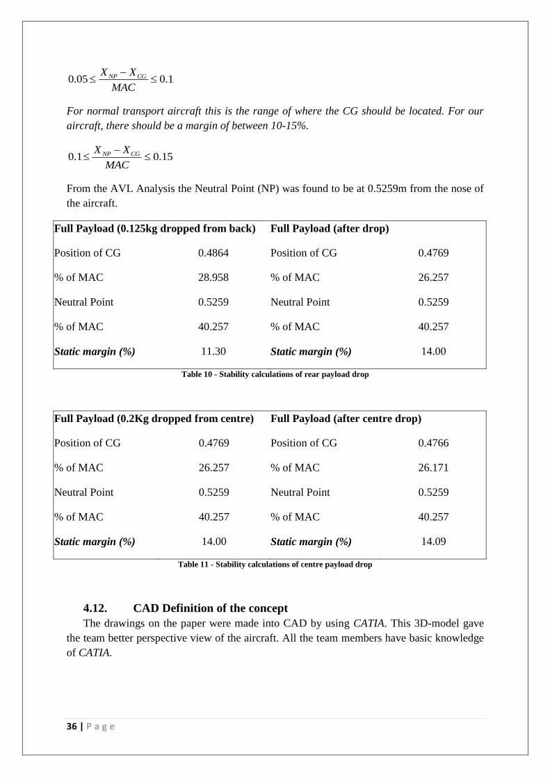
From the AVL Analysis the Neutral Point (NP) was found to be at 0.5259m from the nose of
the aircraft.
Full Payload (0.125kg dropped from back) Full Payload (after drop)
Position of CG 0.4864 Position of CG 0.4769
% of MAC 28.958 % of MAC 26.257
Neutral Point 0.5259 Neutral Point 0.5259
% of MAC 40.257 % of MAC 40.257
Static margin (%) 11.30 Static margin (%) 14.00
Table 10 - Stability calculations of rear payload drop
Full Payload (0.2Kg dropped from centre) Full Payload (after centre drop)
Position of CG 0.4769 Position of CG 0.4766
% of MAC 26.257 % of MAC 26.171
Neutral Point 0.5259 Neutral Point 0.5259
% of MAC 40.257 % of MAC 40.257
Static margin (%) 14.00 Static margin (%) 14.09
Table 11 - Stability calculations of centre payload drop
4.12. CAD Definition of the concept
The drawings on the paper were made into CAD by using CATIA. This 3D-model gave
the team better perspective view of the aircraft. All the team members have basic knowledge
of CATIA.
37 | P a g e
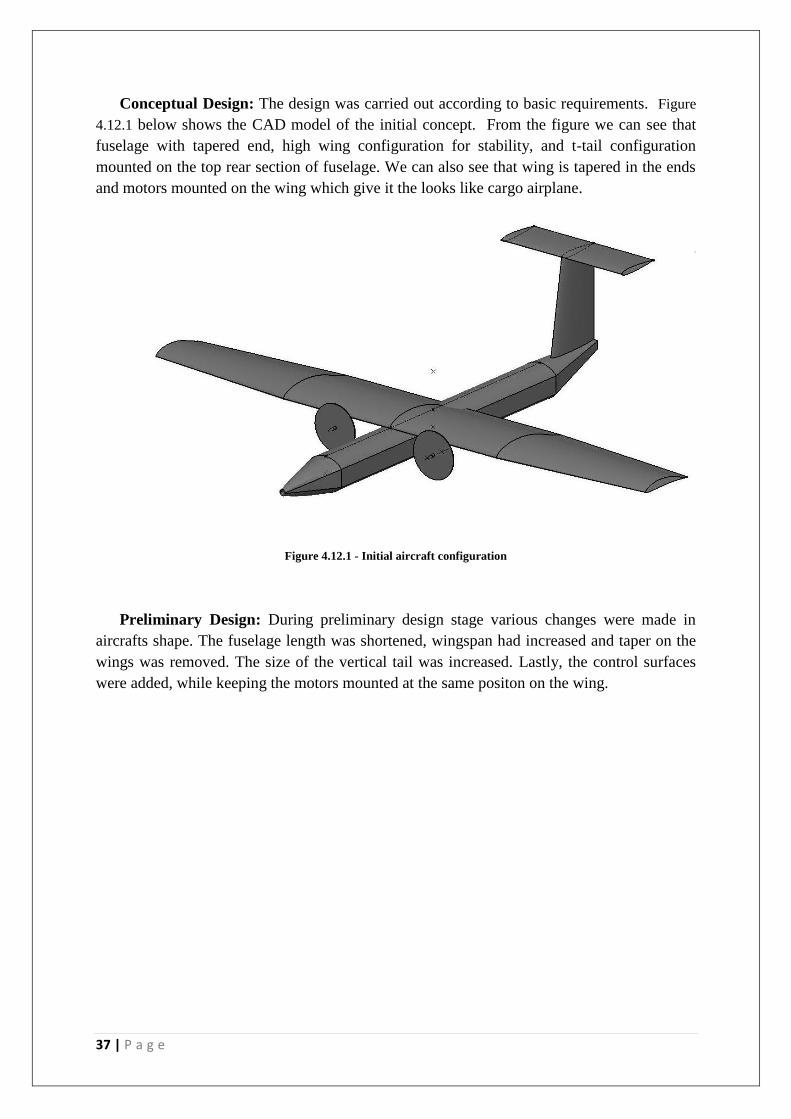
Conceptual Design: The design was carried out according to basic requirements. Figure
4.12.1 below shows the CAD model of the initial concept. From the figure we can see that
fuselage with tapered end, high wing configuration for stability, and t-tail configuration
mounted on the top rear section of fuselage. We can also see that wing is tapered in the ends
and motors mounted on the wing which give it the looks like cargo airplane.
Figure 4.12.1 - Initial aircraft configuration
Preliminary Design: During preliminary design stage various changes were made in
aircrafts shape. The fuselage length was shortened, wingspan had increased and taper on the
wings was removed. The size of the vertical tail was increased. Lastly, the control surfaces
were added, while keeping the motors mounted at the same positon on the wing.

38 | P a g e
Figure 4.12.2 - Final aircraft configuration
5. Preliminary Design
5.1. Wing Structure
The wing structure was designed based on observation of previous model aircraft which
had been manufactured in the past. The main structure would consist of two spars, a front and
rear spar, both having webbing. In order to allow for the whole structure to integrate and fit
together the idea was to keep the rear webbing as a guide for the assembly of the wing
structure. Aside from this there were key areas which needed reinforcement in the structure to
maintain the integrity during flight. These areas included the engine mounts, the wing mount
to the fuselage, and the aileron control surfaces. In the centre wing mount to the fuselage
section stronger reinforced ribs would be used, as well as at the position of the engine mounts.
The aileron sections did not need a large amount of reinforcement; however they were a key
area which needed some attention. Other than these sections, the rest of the ribs were simply
to keep the shape, however due to the nature and size of the wing, the other ribs were also
intended to be of reasonable strength in order to maintain the overall structure. Also, due to
the size of the structure, a centre carbon rod was to be integrated into the structure to keep the
integrity, especially between the engines and across the wing to fuselage connection. This
would provide the best way to transfer the loads across through the structure, as well as keep
the stiffness in this section, which is of necessity.
39 | P a g e
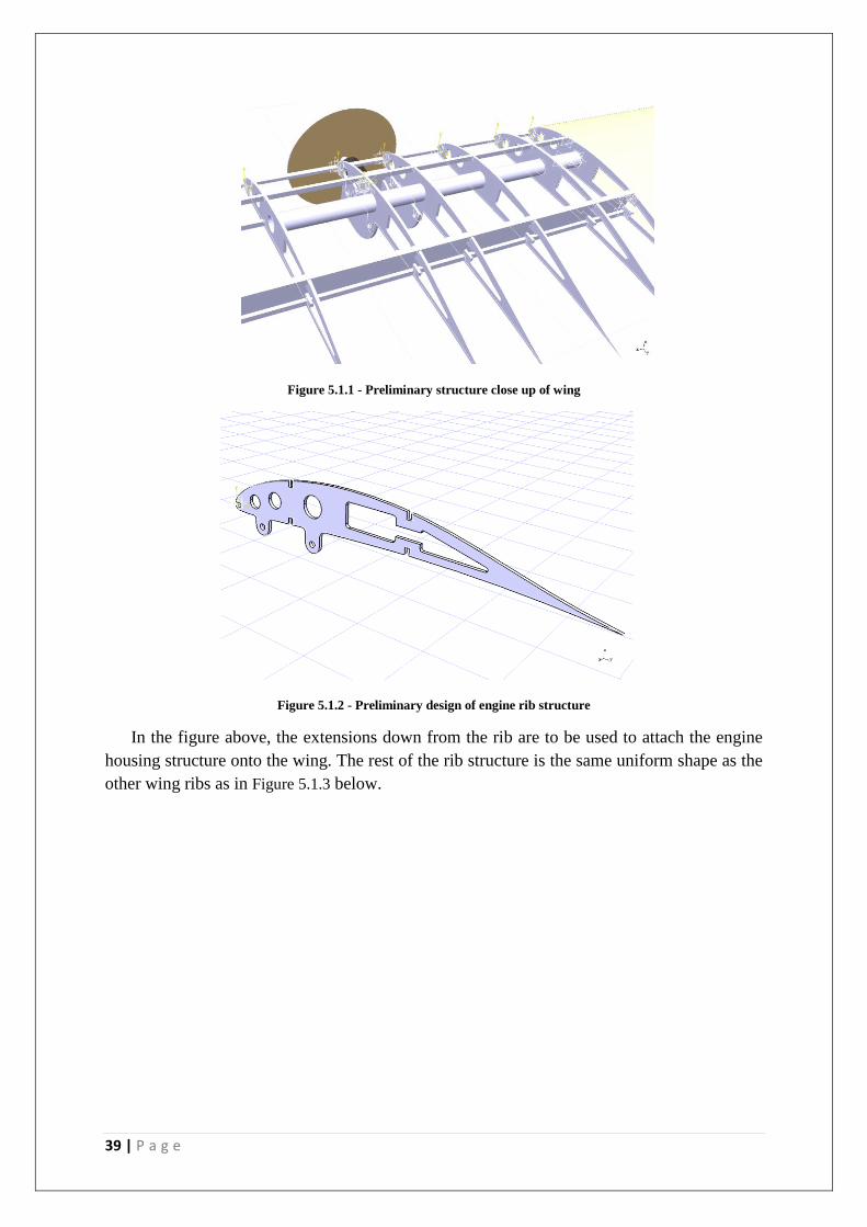
Figure 5.1.1 - Preliminary structure close up of wing
Figure 5.1.2 - Preliminary design of engine rib structure
In the figure above, the extensions down from the rib are to be used to attach the engine
housing structure onto the wing. The rest of the rib structure is the same uniform shape as the
other wing ribs as in Figure 5.1.3 below.

40 | P a g e
Figure 5.1.3 - Preliminary design of main wing rib
Figure 5.1.4 - Preliminary overview of half wing structure
Figure 5.1.4 shows the overview of the wing structure in its preliminary design stage with
the ribs set out. In the figure, the front spar caps and the rear webbing can be seen, as well as
the expected placement for the carbon rod. The rod can be seen to pass through both the main
centre wing structure, (right), and the engine housings, providing extra support to this region.
5.2. Fuselage Structure
In this stage the fuselage structure and load bearing joints were finalised. It was found
that nine ribs along with four longerons should be enough to hold the fuselage together. The
thickness of the ribs was also decided upon during this stage. It was decided that all the ribs
and longerons were to be made out of ply material.
41 | P a g e
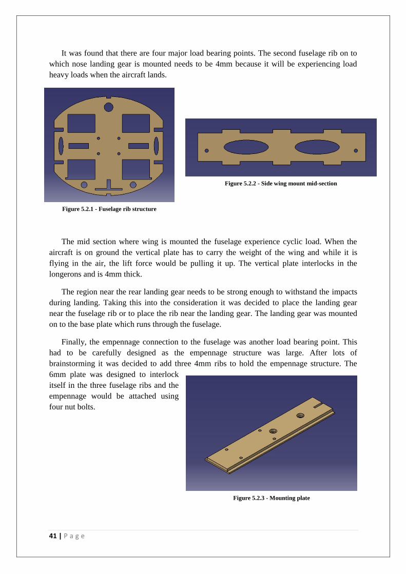
It was found that there are four major load bearing points. The second fuselage rib on to
which nose landing gear is mounted needs to be 4mm because it will be experiencing load
heavy loads when the aircraft lands.
The mid section where wing is mounted the fuselage experience cyclic load. When the
aircraft is on ground the vertical plate has to carry the weight of the wing and while it is
flying in the air, the lift force would be pulling it up. The vertical plate interlocks in the
longerons and is 4mm thick.
The region near the rear landing gear needs to be strong enough to withstand the impacts
during landing. Taking this into the consideration it was decided to place the landing gear
near the fuselage rib or to place the rib near the landing gear. The landing gear was mounted
on to the base plate which runs through the fuselage.
Finally, the empennage connection to the fuselage was another load bearing point. This
had to be carefully designed as the empennage structure was large. After lots of
brainstorming it was decided to add three 4mm ribs to hold the empennage structure. The
6mm plate was designed to interlock
itself in the three fuselage ribs and the
empennage would be attached using
four nut bolts.
Figure 5.2.1 - Fuselage rib structure
Figure 5.2.2 - Side wing mount mid-section
Figure 5.2.3 - Mounting plate
42 | P a g e
5.3. Empennage Structure
The geometry of the tail was decided through calculations of tail volume coefficients,
which provide a representation of the required size of the tail structure. The surface areas for
all types of tails are directly related to the aircrafts wing area. This means that the size of the
tail cannot be determined unless an initial estimation of the aircrafts gross weight and
therefore wing size is first determined.
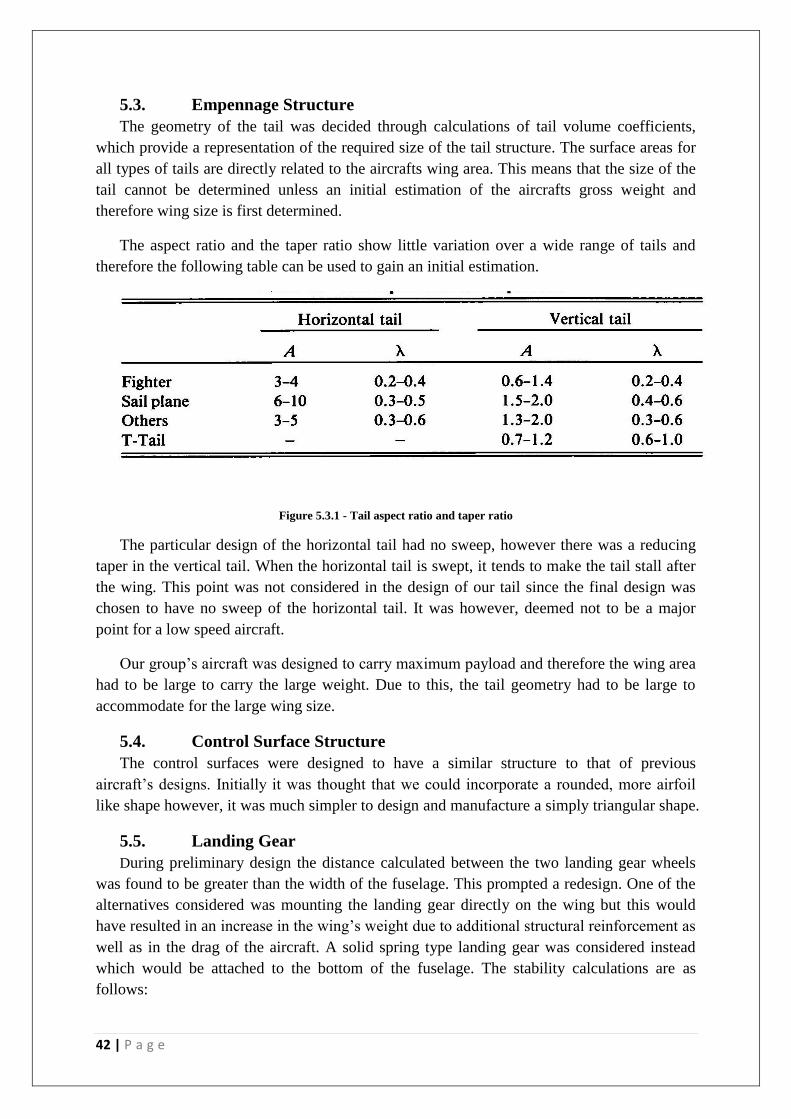
The aspect ratio and the taper ratio show little variation over a wide range of tails and
therefore the following table can be used to gain an initial estimation.
Figure 5.3.1 - Tail aspect ratio and taper ratio
The particular design of the horizontal tail had no sweep, however there was a reducing
taper in the vertical tail. When the horizontal tail is swept, it tends to make the tail stall after
the wing. This point was not considered in the design of our tail since the final design was
chosen to have no sweep of the horizontal tail. It was however, deemed not to be a major
point for a low speed aircraft.
Our group’s aircraft was designed to carry maximum payload and therefore the wing area
had to be large to carry the large weight. Due to this, the tail geometry had to be large to
accommodate for the large wing size.
5.4. Control Surface Structure
The control surfaces were designed to have a similar structure to that of previous
aircraft’s designs. Initially it was thought that we could incorporate a rounded, more airfoil
like shape however, it was much simpler to design and manufacture a simply triangular shape.
5.5. Landing Gear
During preliminary design the distance calculated between the two landing gear wheels
was found to be greater than the width of the fuselage. This prompted a redesign. One of the
alternatives considered was mounting the landing gear directly on the wing but this would
have resulted in an increase in the wing’s weight due to additional structural reinforcement as
well as in the drag of the aircraft. A solid spring type landing gear was considered instead
which would be attached to the bottom of the fuselage. The stability calculations are as
follows:
43 | P a g e
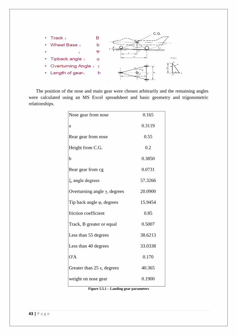
The position of the nose and main gear were chosen arbitrarily and the remaining angles
were calculated using an MS Excel spreadsheet and basic geometry and trigonometric
relationships.
Nose gear from nose 0.165
a 0.3119
Rear gear from nose 0.55
Height from C.G. 0.2
b 0.3850
Rear gear from cg 0.0731
ξ, angle degrees 57.3266
Overturning angle γ, degrees 20.0900
Tip back angle φ, degrees 15.9454
friction coefficient 0.85
Track, B greater or equal 0.5007
Less than 55 degrees 38.6213
Less than 40 degrees 33.0338
O'A 0.170
Greater than 25 ε, degrees 40.365
weight on nose gear 0.1900
Figure 5.5.1 – Landing gear parameters
44 | P a g e
5.6. Integration of Propulsion System
As discussed above, the placement of the engines was to be on the wings. As such there
was a number of ways in which they could be integrated into the structure. The wing could
either be designed to house the engines internally, or there would an external structure which
would house the engine and hang off the wing, like and engine nacelle. The first method of
designing the engines to be housed into the wing structure would mean some changes to the
wing structure and also make the connection a little more difficult that without this. Also, the
size into the wing structure would have to be considered, and possibly the thickness ratio
t
c
of the wing may have to be reconsidered to keep an aerodynamic shape on the wing. The
latter option allowed for a more ease of access and maintenance approach as well as keep the
two parts separate. It was decided that we would move towards the external mounting
engines to both provide a separate space for the engines to be located, but also allow for the
engines to be removable from the wing in the event of maintenance.
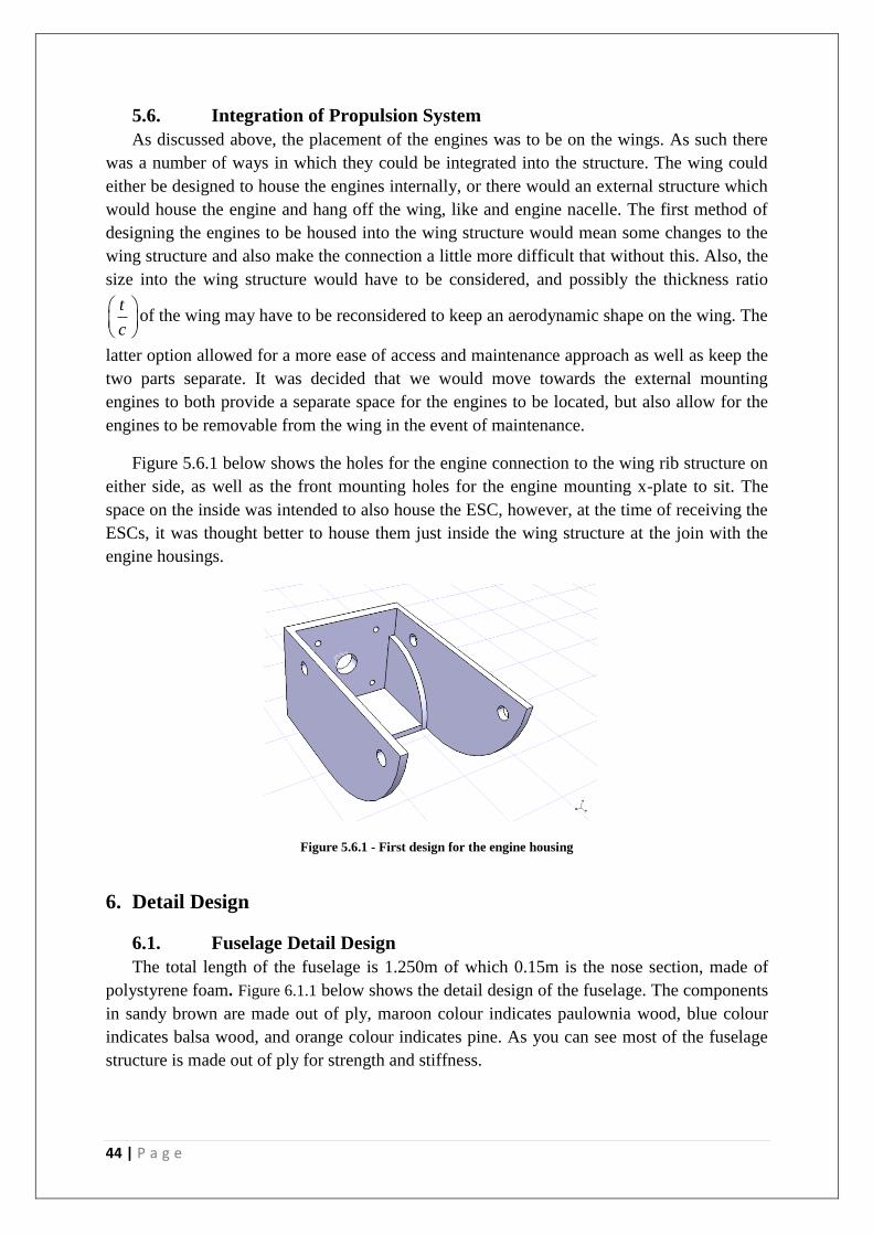
Figure 5.6.1 below shows the holes for the engine connection to the wing rib structure on
either side, as well as the front mounting holes for the engine mounting x-plate to sit. The
space on the inside was intended to also house the ESC, however, at the time of receiving the
ESCs, it was thought better to house them just inside the wing structure at the join with the
engine housings.
Figure 5.6.1 - First design for the engine housing
6. Detail Design
6.1. Fuselage Detail Design
The total length of the fuselage is 1.250m of which 0.15m is the nose section, made of
polystyrene foam. Figure 6.1.1 below shows the detail design of the fuselage. The components
in sandy brown are made out of ply, maroon colour indicates paulownia wood, blue colour
indicates balsa wood, and orange colour indicates pine. As you can see most of the fuselage
structure is made out of ply for strength and stiffness.

45 | P a g e
Figure 6.1.1 - Overview of fuselage
The fuselage has a total of nine ribs and four longerons running throughout the length. All
longerons are 4mm thick and the thickness of ribs is 3mm or 4mm. The design was made in
such a way that the ribs and longerons locks into themselves. Another important feature of
the fuselage was its base plate. The base plate was in the shape of an I-beam. This was to
control the torsion in the fuselage and ensure that fuselage is straight during fabrication. The
I-beam comprises of three plates that
lock together and are glued. This plate
would be carrying the batteries and
payload. The base plate was divided
into two section the front and rear
section. Figure 6.1.2 on the right shows
the I-beam.
I-beam
Figure 6.1.2 - I-beam structure

46 | P a g e
The 4mm vertical ply plate is added between two longerons for wing mounting. The
vertical plate locks itself in the top and bottom longerons and is then glued together. The
wing is secured using four 3.5mm nut bolts, which can be accessed through mid section
payload door. The four ribs from the front was made flat on the top and was positioned in
such way that the web spar of the wing rest on it.
Flat top on the rib
Vertical Plate and
holes for wing mount.
Special plate was added in the tail section of the fuselage for the empennage mounting. The
plate is 6mm thick and has two 5mm holes for carbon fibre rod and four 3.5mm holes for nut
bolts. The plate is glued to the three fuselage ribs.
Empennage
mounting plate
Figure 6.1.3 - Wing mounting section
Figure 6.1.4 - Empennage mounting plate
47 | P a g e
The rear section of the fuselage is made out of paulownia rods as it is not carrying any
load, and is only providing shape to the fuselage.
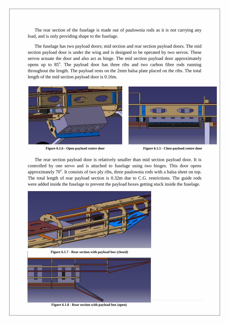
The fuselage has two payload doors; mid section and rear section payload doors. The mid
section payload door is under the wing and is designed to be operated by two servos. These
servos actuate the door and also act as hinge. The mid section payload door approximately
opens up to 85o. The payload door has three ribs and two carbon fibre rods running
throughout the length. The payload rests on the 2mm balsa plate placed on the ribs. The total
length of the mid section payload door is 0.16m.
The rear section payload door is relatively smaller than mid section payload door. It is
controlled by one servo and is attached to fuselage using two hinges. This door opens
approximately 70o. It consists of two ply ribs, three paulownia rods with a balsa sheet on top.
The total length of rear payload section is 0.32m due to C.G. restrictions. The guide rods
were added inside the fuselage to prevent the payload boxes getting stuck inside the fuselage.
Figure 6.1.6 - Open payload centre door Figure 6.1.5 - Close payload centre door
Figure 6.1.7 - Rear section with payload box (closed)
Figure 6.1.8 - Rear section with payload box (open)
48 | P a g e
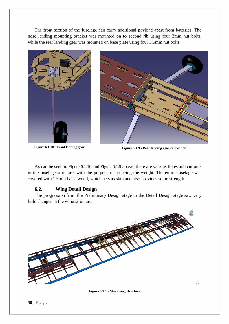
The front section of the fuselage can carry additional payload apart from batteries. The
nose landing mounting bracket was mounted on to second rib using four 2mm nut bolts,
while the rear landing gear was mounted on base plate using four 3.5mm nut bolts.
As can be seen in Figure 6.1.10 and Figure 6.1.9 above, there are various holes and cut outs
in the fuselage structure, with the purpose of reducing the weight. The entire fuselage was
covered with 1.5mm balsa wood, which acts as skin and also provides some strength.
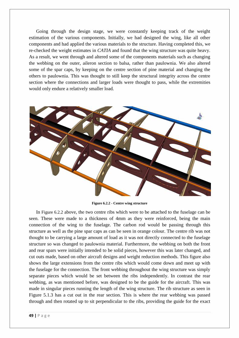
6.2. Wing Detail Design
The progression from the Preliminary Design stage to the Detail Design stage saw very
little changes in the wing structure.
Figure 6.2.1 - Main wing structure
Figure 6.1.10 - Front landing gear Figure 6.1.9 - Rear landing gear connection
49 | P a g e
Going through the design stage, we were constantly keeping track of the weight
estimation of the various components. Initially, we had designed the wing, like all other
components and had applied the various materials to the structure. Having completed this, we
re-checked the weight estimates in CATIA and found that the wing structure was quite heavy.
As a result, we went through and altered some of the components materials such as changing
the webbing on the outer, aileron section to balsa, rather than paulownia. We also altered
some of the spar caps, by keeping on the centre section of pine material and changing the
others to paulownia. This was thought to still keep the structural integrity across the centre
section where the connections and larger loads were thought to pass, while the extremities
would only endure a relatively smaller load.
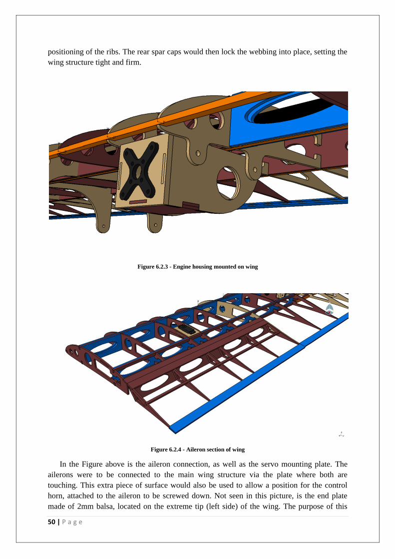
Figure 6.2.2 - Centre wing structure
In Figure 6.2.2 above, the two centre ribs which were to be attached to the fuselage can be
seen. These were made to a thickness of 4mm as they were reinforced, being the main
connection of the wing to the fuselage. The carbon rod would be passing through this
structure as well as the pine spar caps as can be seen in orange colour. The centre rib was not
thought to be carrying a large amount of load as it was not directly connected to the fuselage
structure so was changed to paulownia material. Furthermore, the webbing on both the front
and rear spars were initially intended to be solid pieces, however this was later changed, and
cut outs made, based on other aircraft designs and weight reduction methods. This figure also
shows the large extensions from the centre ribs which would come down and meet up with
the fuselage for the connection. The front webbing throughout the wing structure was simply
separate pieces which would be set between the ribs independently. In contrast the rear
webbing, as was mentioned before, was designed to be the guide for the aircraft. This was
made in singular pieces running the length of the wing structure. The rib structure as seen in
Figure 5.1.3 has a cut out in the rear section. This is where the rear webbing was passed
through and then rotated up to sit perpendicular to the ribs, providing the guide for the exact
50 | P a g e
positioning of the ribs. The rear spar caps would then lock the webbing into place, setting the
wing structure tight and firm.
Figure 6.2.3 - Engine housing mounted on wing
Figure 6.2.4 - Aileron section of wing
In the Figure above is the aileron connection, as well as the servo mounting plate. The
ailerons were to be connected to the main wing structure via the plate where both are
touching. This extra piece of surface would also be used to allow a position for the control
horn, attached to the aileron to be screwed down. Not seen in this picture, is the end plate
made of 2mm balsa, located on the extreme tip (left side) of the wing. The purpose of this
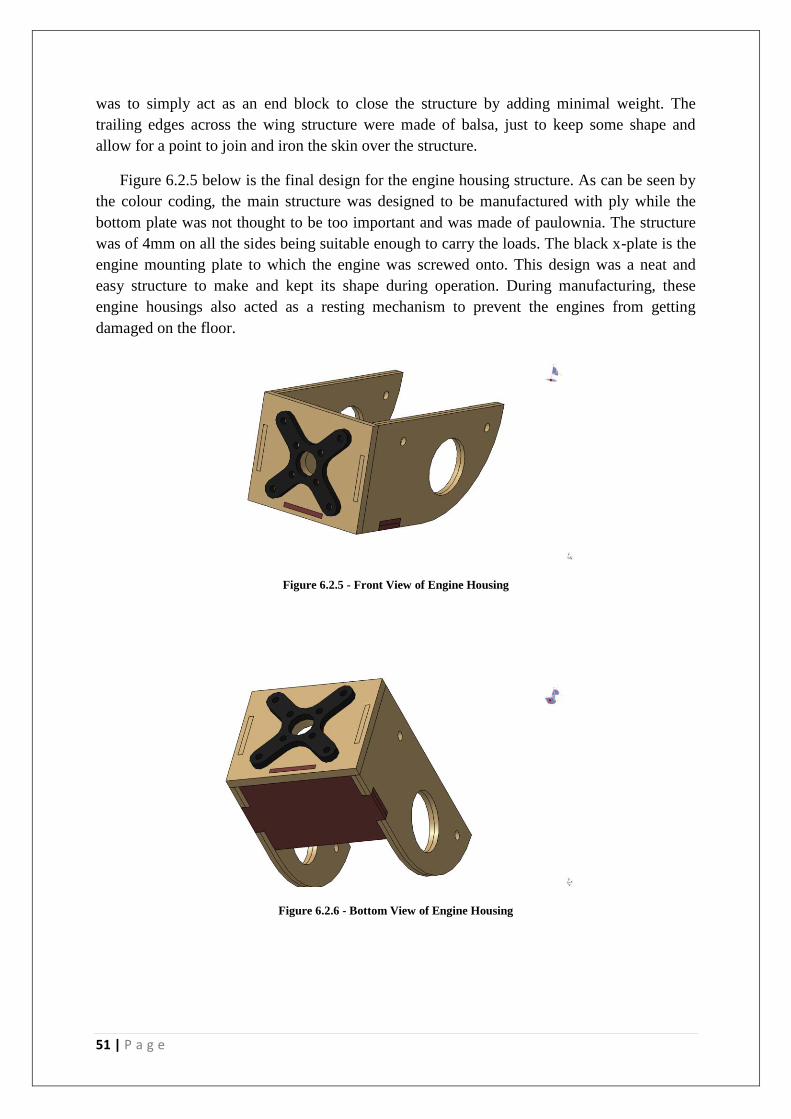
51 | P a g e
was to simply act as an end block to close the structure by adding minimal weight. The
trailing edges across the wing structure were made of balsa, just to keep some shape and
allow for a point to join and iron the skin over the structure.
Figure 6.2.5 below is the final design for the engine housing structure. As can be seen by
the colour coding, the main structure was designed to be manufactured with ply while the
bottom plate was not thought to be too important and was made of paulownia. The structure
was of 4mm on all the sides being suitable enough to carry the loads. The black x-plate is the
engine mounting plate to which the engine was screwed onto. This design was a neat and
easy structure to make and kept its shape during operation. During manufacturing, these
engine housings also acted as a resting mechanism to prevent the engines from getting
damaged on the floor.
Figure 6.2.5 - Front View of Engine Housing
Figure 6.2.6 - Bottom View of Engine Housing

52 | P a g e
6.3. Empennage Detail Design
6.3.1. Horizontal Tail:
The horizontal tail was of a relatively simple design since it had neither twist nor
sweep. The airfoil was constructed from a NACA0012 airfoil, which is a symmetrical airfoil
about its axis and of 12% thickness. Using a symmetrical airfoil meant that no lift would be
produced when the tail is at zero angle of incidence. This is desirable, as the tail requires no
lift when the aircraft is in level flight. The horizontal tail was mounted on the vertical tail at
zero angle of incidence and as such there is equal flow and pressure on the top and bottom
surfaces of the horizontal tail, thus, no lift is produced by the horizontal tail.
It was 0.84m long from tip to tip with a chord length of 0.28m. The structure contains
10 ribs spaced at a distance of approximately 0.1m apart. The end ribs were made of plywood
as well as the two middle ribs (spaced at 3cm). The rest were made of paulownia. A 10mm
diameter carbon rod ran through the front of the horizontal tail and a webbed spar ran through
the rear to provide stiffness and to transfer the loads experienced in flight. Originally, the
horizontal tail was designed with two carbon rods that ran through the front and the rear of
the tail. However, this proved to cause some problems related to geometric twist, the rear
carbon rod was reduced in length to approximately 3.5cm for this reason. These problems
will be discussed later.
Figure 6.3.1.1 - Detail design of the Horizontal tail
A 5x5 paulownia spar ran across the entire leading edge of the horizontal tail, which
kept the ribs spaced evenly and provided a proper shape for the skin. The spars also provide
rigidity for the entire structure. Two more paulownia spars ran across the top and bottom of
the structure at approximately 25% of the chord length and then the webbed spar at
approximately 75% of the chord. All these spars provided shape and rigidity to the structure.
6.3.2. Servo Plate:
A simple rectangular servo mounting plate was also attached to one side of the
mounting block, which provided a location for the servo to be mounted. This was made out of
plywood, as it was required to be strong since there is a relatively large torque from the servo
when it moves. This servo plate was glued to ribs 4, 5 and the top spar of the horizontal tail.
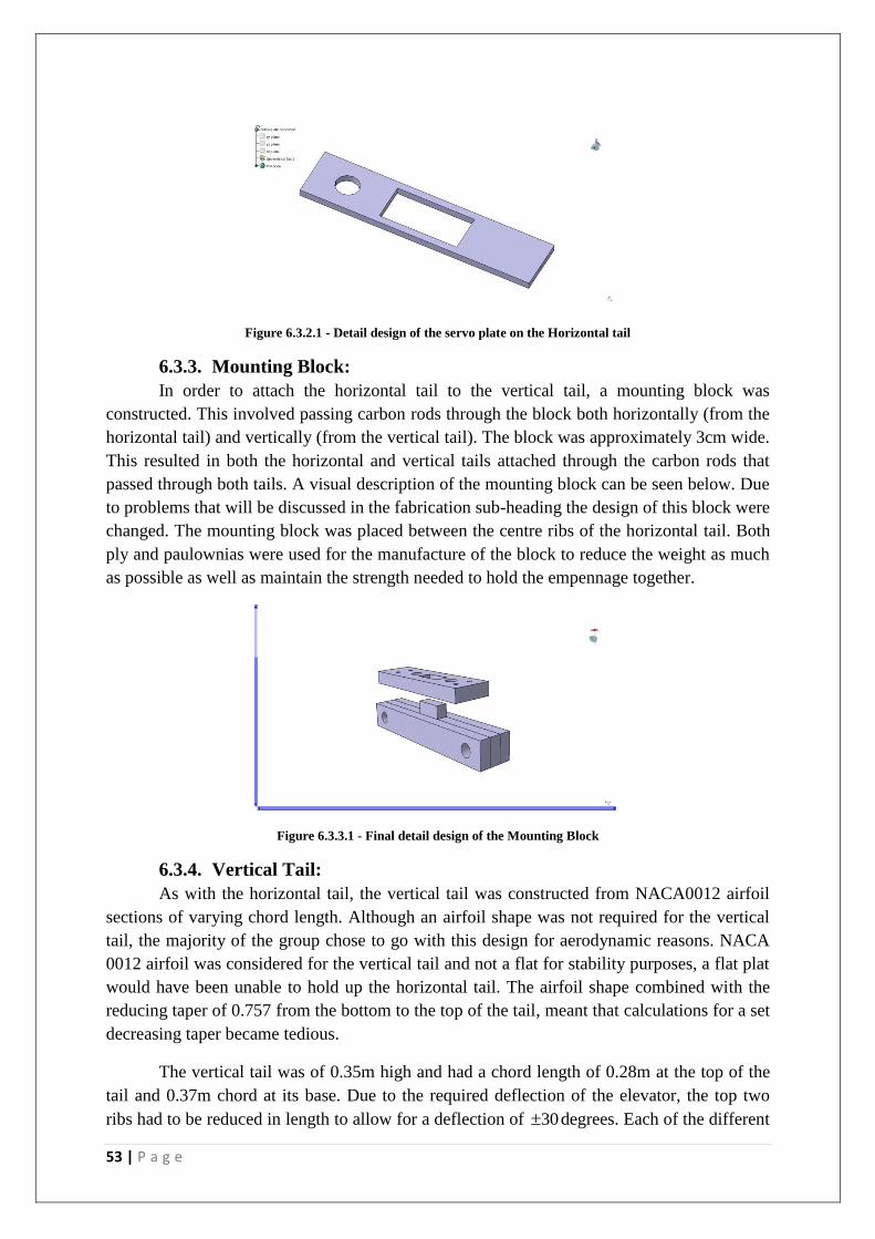
53 | P a g e
Figure 6.3.2.1 - Detail design of the servo plate on the Horizontal tail
6.3.3. Mounting Block:
In order to attach the horizontal tail to the vertical tail, a mounting block was
constructed. This involved passing carbon rods through the block both horizontally (from the
horizontal tail) and vertically (from the vertical tail). The block was approximately 3cm wide.
This resulted in both the horizontal and vertical tails attached through the carbon rods that
passed through both tails. A visual description of the mounting block can be seen below. Due
to problems that will be discussed in the fabrication sub-heading the design of this block were
changed. The mounting block was placed between the centre ribs of the horizontal tail. Both
ply and paulownias were used for the manufacture of the block to reduce the weight as much
as possible as well as maintain the strength needed to hold the empennage together.
Figure 6.3.3.1 - Final detail design of the Mounting Block
6.3.4. Vertical Tail:
As with the horizontal tail, the vertical tail was constructed from NACA0012 airfoil
sections of varying chord length. Although an airfoil shape was not required for the vertical
tail, the majority of the group chose to go with this design for aerodynamic reasons. NACA
0012 airfoil was considered for the vertical tail and not a flat for stability purposes, a flat plat
would have been unable to hold up the horizontal tail. The airfoil shape combined with the
reducing taper of 0.757 from the bottom to the top of the tail, meant that calculations for a set
decreasing taper became tedious.
The vertical tail was of 0.35m high and had a chord length of 0.28m at the top of the
tail and 0.37m chord at its base. Due to the required deflection of the elevator, the top two
ribs had to be reduced in length to allow for a deflection of 30 degrees. Each of the different
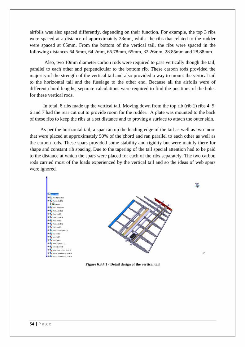
54 | P a g e
airfoils was also spaced differently, depending on their function. For example, the top 3 ribs
were spaced at a distance of approximately 28mm, whilst the ribs that related to the rudder
were spaced at 65mm. From the bottom of the vertical tail, the ribs were spaced in the
following distances 64.5mm, 64.2mm, 65.78mm, 65mm, 32.26mm, 28.85mm and 28.88mm.
Also, two 10mm diameter carbon rods were required to pass vertically though the tail,
parallel to each other and perpendicular to the bottom rib. These carbon rods provided the
majority of the strength of the vertical tail and also provided a way to mount the vertical tail
to the horizontal tail and the fuselage to the other end. Because all the airfoils were of
different chord lengths, separate calculations were required to find the positions of the holes
for these vertical rods.
In total, 8 ribs made up the vertical tail. Moving down from the top rib (rib 1) ribs 4, 5,
6 and 7 had the rear cut out to provide room for the rudder. A plate was mounted to the back
of these ribs to keep the ribs at a set distance and to proving a surface to attach the outer skin.
As per the horizontal tail, a spar ran up the leading edge of the tail as well as two more
that were placed at approximately 50% of the chord and ran parallel to each other as well as
the carbon rods. These spars provided some stability and rigidity but were mainly there for
shape and constant rib spacing. Due to the tapering of the tail special attention had to be paid
to the distance at which the spars were placed for each of the ribs separately. The two carbon
rods carried most of the loads experienced by the vertical tail and so the ideas of web spars
were ignored.
Figure 6.3.4.1 - Detail design of the vertical tail
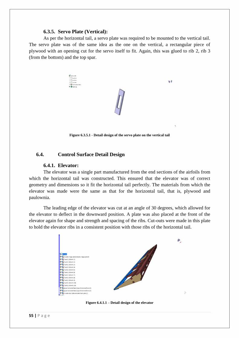
55 | P a g e
6.3.5. Servo Plate (Vertical):
As per the horizontal tail, a servo plate was required to be mounted to the vertical tail.
The servo plate was of the same idea as the one on the vertical, a rectangular piece of
plywood with an opening cut for the servo itself to fit. Again, this was glued to rib 2, rib 3
(from the bottom) and the top spar.
Figure 6.3.5.1 - Detail design of the servo plate on the vertical tail
6.4. Control Surface Detail Design
6.4.1. Elevator:
The elevator was a single part manufactured from the end sections of the airfoils from
which the horizontal tail was constructed. This ensured that the elevator was of correct
geometry and dimensions so it fit the horizontal tail perfectly. The materials from which the
elevator was made were the same as that for the horizontal tail, that is, plywood and
paulownia.
The leading edge of the elevator was cut at an angle of 30 degrees, which allowed for
the elevator to deflect in the downward position. A plate was also placed at the front of the
elevator again for shape and strength and spacing of the ribs. Cut-outs were made in this plate
to hold the elevator ribs in a consistent position with those ribs of the horizontal tail.
Figure 6.4.1.1 – Detail design of the elevator

56 | P a g e
Two spars ran on the top and the bottom of the elevator airfoil sections to provide
shape and rigidity. As well as this, backing plates were attached to the very rear of the
elevator, which extended to the trailing edge of the airfoil sections. These back plates were
attached for shape and a place to attach the outer skin. They were constructed of 1.5mm ply,
which was ample for their use. A paulownia plate also ran along the top of leading edge of
the elevator, which provided a place to mount the servo connection. As well as this function,
it also provides shape for the outer skin.
6.4.2. Rudder:
Again, the rudder was constructed from the end sections of the ribs that the rudder
relates to. The rudder chord was 0.15m and was of a height of 0.26m. It consisted of 4 ribs
spaced at 6.5cm apart made from paulownia. As per the elevator, the rudder has back plates
mounted flush with the trailing edge on the top and bottom of the airfoil as well as a front
plate that kept the spacing of the ribs constant throughout the structure. Another plate was
also mounted on the top of the airfoil at the leading edge to provide a surface to mount the
servo connection to as well as the outer skin. This plate was of approximately 15mm long and
made of paulownia.
Two 5x5mm spars ran the entire length of the rudder on the top and bottom of the ribs
for shape and load support. These were located at approximately 25% of the chord length of
the rudder rib. In order for the rudder to deflect, an angle of 40 degrees was cut out from the
leading edge. This can be seen in the diagram that follows.
Figure 6.4.2.1 - Detail design of the rudder
6.4.3. Aileron:
The aileron was designed to be manufactured out of ply as it was thought that balsa
would not have the correct stiffness to support the structure. The ailerons is the main
component which is used for controlling the aircraft in a roll and would have quite high loads
associated with them in flight. Furthermore, the control surfaces are relatively large and
would be better to be safe with this design than have them fail in flight. As can be seen in the
figure below, the front plate was designed to be the guide for the construction of the aileron.
This was made of paulownia and allowed for the aileron ribs to be inserted directly into the
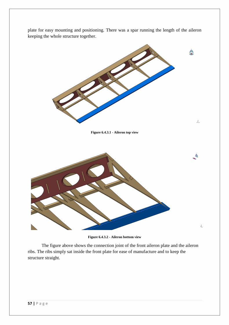
57 | P a g e
plate for easy mounting and positioning. There was a spar running the length of the aileron
keeping the whole structure together.
Figure 6.4.3.1 - Aileron top view
Figure 6.4.3.2 - Aileron bottom view
The figure above shows the connection joint of the front aileron plate and the aileron
ribs. The ribs simply sat inside the front plate for ease of manufacture and to keep the
structure straight.
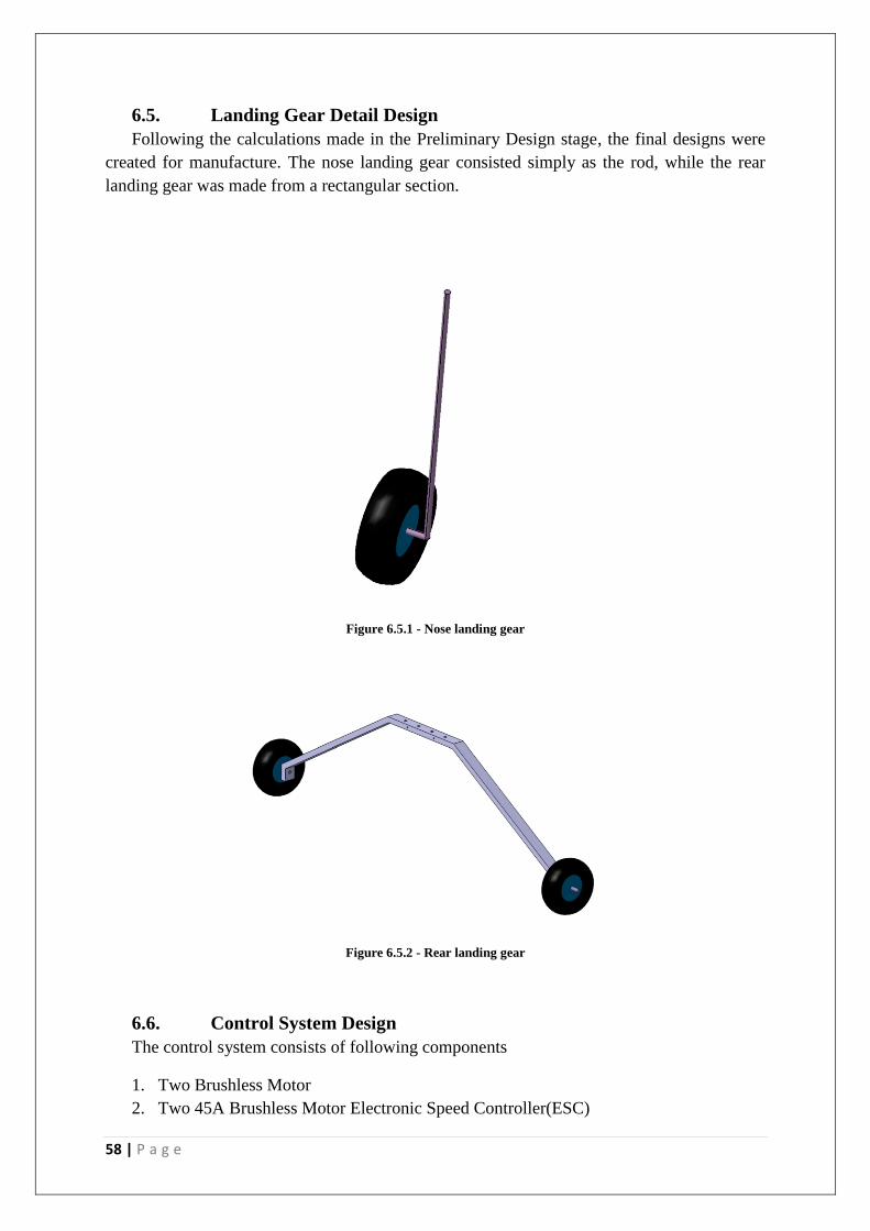
58 | P a g e
6.5. Landing Gear Detail Design
Following the calculations made in the Preliminary Design stage, the final designs were
created for manufacture. The nose landing gear consisted simply as the rod, while the rear
landing gear was made from a rectangular section.
Figure 6.5.1 - Nose landing gear
Figure 6.5.2 - Rear landing gear
6.6. Control System Design
The control system consists of following components
1. Two Brushless Motor
2. Two 45A Brushless Motor Electronic Speed Controller(ESC)
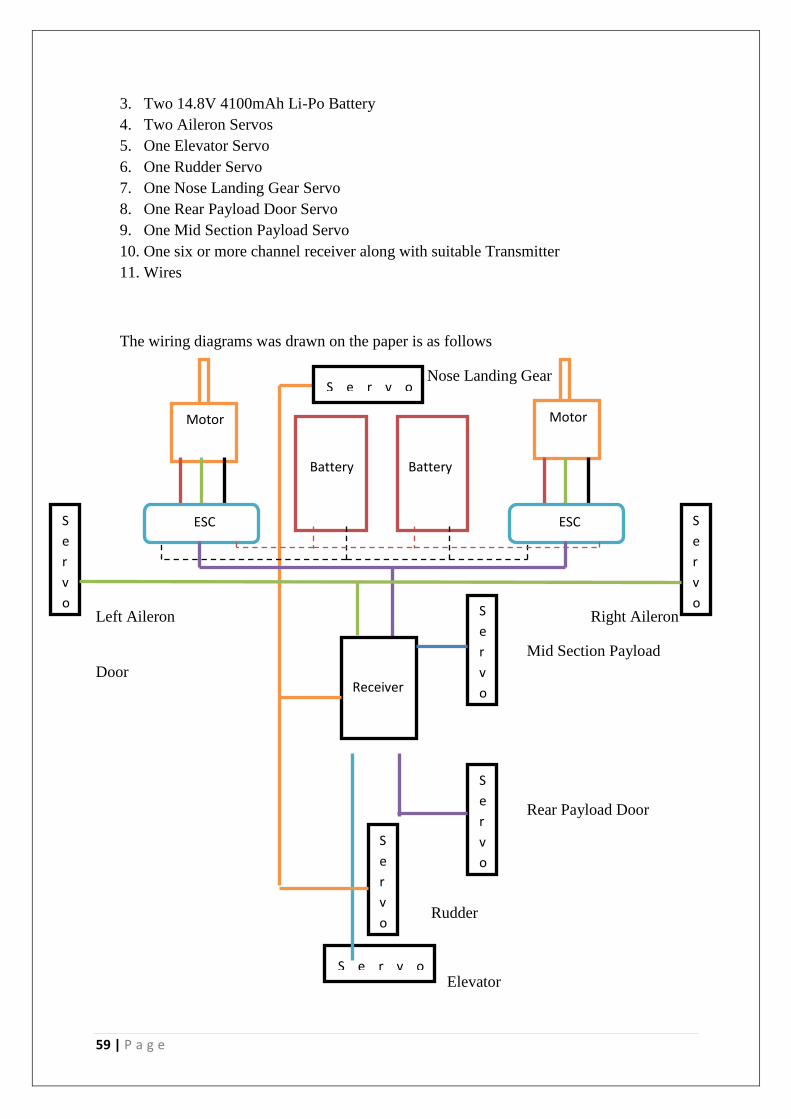
59 | P a g e
3. Two 14.8V 4100mAh Li-Po Battery
4. Two Aileron Servos
5. One Elevator Servo
6. One Rudder Servo
7. One Nose Landing Gear Servo
8. One Rear Payload Door Servo
9. One Mid Section Payload Servo
10. One six or more channel receiver along with suitable Transmitter
11. Wires
The wiring diagrams was drawn on the paper is as follows
Nose Landing Gear
Left Aileron Right Aileron
Mid Section Payload
Door
Rear Payload Door
Rudder
Elevator
Motor
S e r v o
Battery
Battery
Motor
S
e
r
v
o
S
e
r
v
o
ESC ESC
Receiver
S e r v o
S
e
r
v
o
S
e
r
v
o
S
e
r
v
o

60 | P a g e
7. Fabrication
7.1. Preparation
The 2D-Laser Cutting Machine was used to cut the parts of the aircraft. The parts made in
CATIA need to be changed into .doff format and then using AutoCAD arranged in sheets,
which will be cut in the Laser Machine. The parts in AutoCAD need to be oriented in the
right direction so that they can carry the load.
While selecting the wood sheets check the sheets for any cracks, damage or warping as it
might cause problem in the structural integrity of the aircraft.
All the joints in the aircraft are glued together using two part epoxy (AB glue). This glue
provides strong wood to wood joints. Some parts of the aircraft were attached using
cyanoacrylate glue (super glue) as it dries faster. The testing of the glue wasn’t required
because tutors specified which glue to use where. The two part epoxy glue is the best
followed by cyanoacrylate glue, with the last being PVA glue.
7.2. Fuselage Fabrication
The first step of fabrication was to cut major components like ribs, longerons and base
plates. It took almost 24 hours to cut all parts in the Laser Cutting Machine. The 2mm parts
were glued together using AB glue to form 4mm parts. It took approximately two days to
glue all the parts and form required parts.
As the fuselage was designed in such way that everything locks itself in place, a rough
assembly of fuselage without glue was performed. During this process it was found that the
rear section of the fuselage had a slight bit of torsion to it. After consulting tutors, it was
thought that the balsa wood skin and the thermal shrink film covering, would correct it.
After checking everything in the rough assembly, it took two days to completely assemble
the fuselage and both the payload doors using glue. The next step was to add servos for the
nose landing gear, mid section payload and rear section payload doors.
During this stage it was found that mid section payload door could not work with two
servos. As both the servos work in opposite direction it was impossible to connect them using
a single receiver channel. In order to solve this problem it was decided to remove one servo
and replace it with a hinge. It was estimated that mid section payload door could carry
approximately around 500g with the given two servos; however, this capacity was reduced to
half with the removal of one servo.
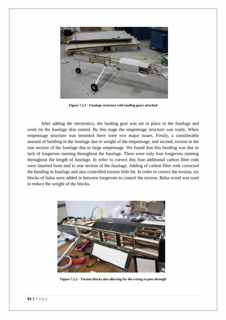
61 | P a g e
Figure 7.2.1 - Fuselage structure with landing gears attached
After adding the electronics, the landing gear was set in place in the fuselage and
work on the fuselage skin started. By this stage the empennage structure was ready. When
empennage structure was mounted there were two major issues. Firstly, a considerable
amount of bending in the fuselage due to weight of the empennage, and second, torsion in the
rear section of the fuselage due to large empennage. We found that this bending was due to
lack of longerons running throughout the fuselage. There were only four longerons running
throughout the length of fuselage. In order to correct this four additional carbon fibre rods
were inserted from mid to rear section of the fuselage. Adding of carbon fibre rods corrected
the bending in fuselage and also controlled torsion little bit. In order to correct the torsion, six
blocks of balsa were added in between longerons to control the torsion. Balsa wood was used
to reduce the weight of the blocks.
Figure 7.2.2 - Torsion blocks also allowing for the wiring to pass through

62 | P a g e
Before adding 1.5mm balsa skin, whole fuselage was sanded using sand paper and
sanding machine to remove excess glue and make the surface smoother. To give improve the
aerodynamic properties and aesthetics; thermal shrink film covering was used.
The total weight of the fuselage along with the landing gears and parts of controls system
was 1.075kg and estimated weight in CATIA was 1.103kg. This proves that the fuselage is
lighter than what it was expected.
7.3. Wing Fabrication
The wing structure was fairly simply to construct given the amount of time and
consideration placed in the detail design phase. However, not having prior knowledge of
manufacturing of materials and structures before some minor complications arose.
Figure 7.3.1 - Wing structure with guide
As can be seen in the figure above, the wing structure was a little more difficult to
manufacture that was planned. Even thought the structure was designed to have the rear spar
act as the guide for the wing fabrication, the structure was not completely straight due to
flaws in the wood structure as well as slight gaps between components. When placed together
the components we slightly free to move a few degrees. This meant that they would not line
up entirely straight leading to a slightly skewed wing. This problem was picked up early and
guides, with markings of the relative positions of the ribs was made and taped to the table.
The wing structure was then taped down to the guide and altered until the structure was
deemed straight. This problem may have been avoided if another guide were integrated into
the structure. With two connections that lock down, the structure would be more limited in its
movements and be easier to correct. However, overcoming this problem was achieved and a
fairly straight wing was manufactured as can be seen in the following figures.
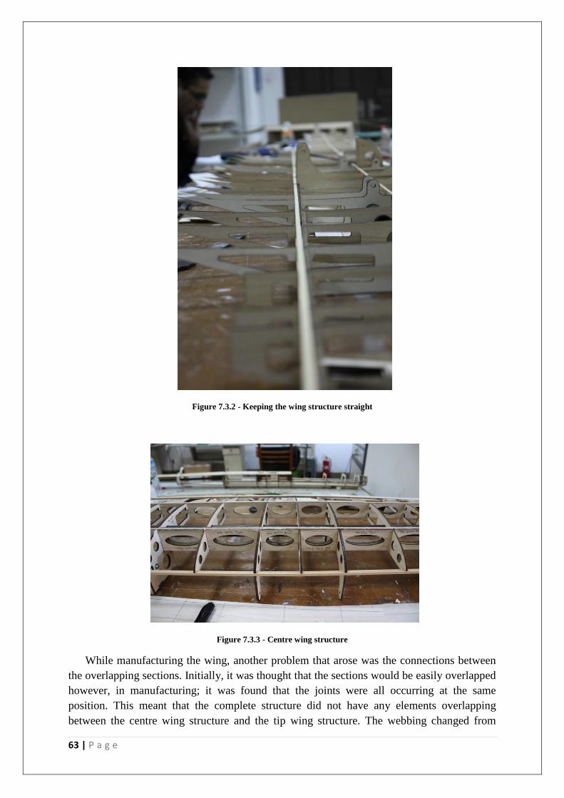
63 | P a g e
Figure 7.3.2 - Keeping the wing structure straight
Figure 7.3.3 - Centre wing structure
While manufacturing the wing, another problem that arose was the connections between
the overlapping sections. Initially, it was thought that the sections would be easily overlapped
however, in manufacturing; it was found that the joints were all occurring at the same
position. This meant that the complete structure did not have any elements overlapping
between the centre wing structure and the tip wing structure. The webbing changed from
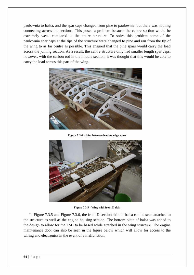
64 | P a g e
paulownia to balsa, and the spar caps changed from pine to paulownia, but there was nothing
connecting across the sections. This posed a problem because the centre section would be
extremely weak compared to the entire structure. To solve this problem some of the
paulownia spar caps at the tips of the structure were changed to pine and ran from the tip of
the wing to as far centre as possible. This ensured that the pine spars would carry the load
across the joining section. As a result, the centre structure only had smaller length spar caps,
however, with the carbon rod in the middle section, it was thought that this would be able to
carry the load across this part of the wing.
Figure 7.3.4 - Joint between leading edge spars
Figure 7.3.5 - Wing with front D skin
In Figure 7.3.5 and Figure 7.3.6, the front D section skin of balsa can be seen attached to
the structure as well as the engine housing section. The bottom plate of balsa was added to
the design to allow for the ESC to be based while attached in the wing structure. The engine
maintenance door can also be seen in the figure below which will allow for access to the
wiring and electronics in the event of a malfunction.
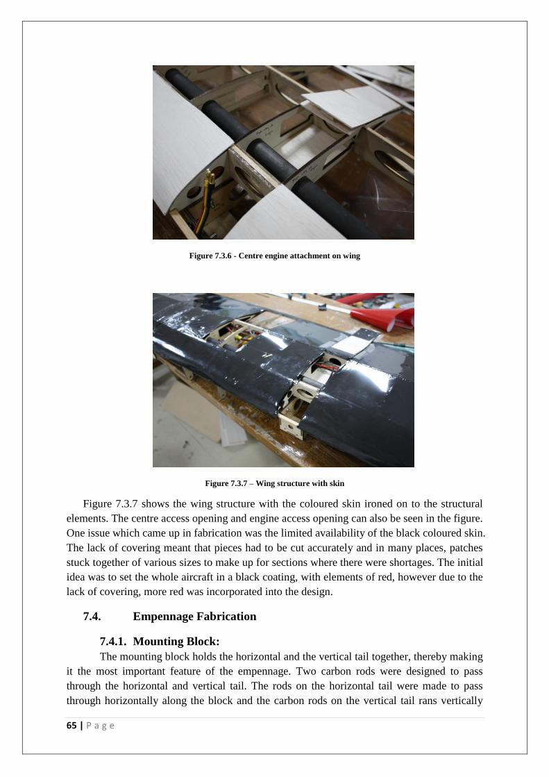
65 | P a g e
Figure 7.3.6 - Centre engine attachment on wing
Figure 7.3.7 – Wing structure with skin
Figure 7.3.7 shows the wing structure with the coloured skin ironed on to the structural
elements. The centre access opening and engine access opening can also be seen in the figure.
One issue which came up in fabrication was the limited availability of the black coloured skin.
The lack of covering meant that pieces had to be cut accurately and in many places, patches
stuck together of various sizes to make up for sections where there were shortages. The initial
idea was to set the whole aircraft in a black coating, with elements of red, however due to the
lack of covering, more red was incorporated into the design.
7.4. Empennage Fabrication
7.4.1. Mounting Block:
The mounting block holds the horizontal and the vertical tail together, thereby making
it the most important feature of the empennage. Two carbon rods were designed to pass
through the horizontal and vertical tail. The rods on the horizontal tail were made to pass
through horizontally along the block and the carbon rods on the vertical tail rans vertically
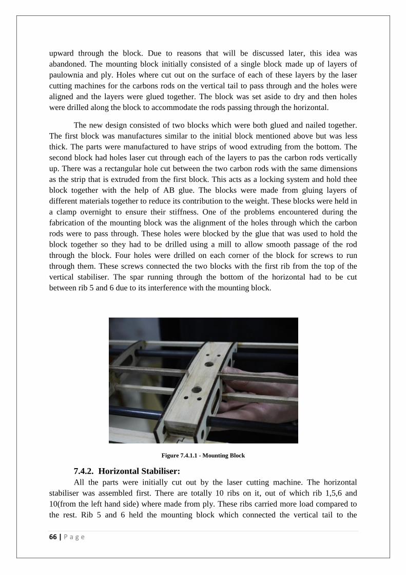
66 | P a g e
upward through the block. Due to reasons that will be discussed later, this idea was
abandoned. The mounting block initially consisted of a single block made up of layers of
paulownia and ply. Holes where cut out on the surface of each of these layers by the laser
cutting machines for the carbons rods on the vertical tail to pass through and the holes were
aligned and the layers were glued together. The block was set aside to dry and then holes
were drilled along the block to accommodate the rods passing through the horizontal.
The new design consisted of two blocks which were both glued and nailed together.
The first block was manufactures similar to the initial block mentioned above but was less
thick. The parts were manufactured to have strips of wood extruding from the bottom. The
second block had holes laser cut through each of the layers to pas the carbon rods vertically
up. There was a rectangular hole cut between the two carbon rods with the same dimensions
as the strip that is extruded from the first block. This acts as a locking system and hold thee
block together with the help of AB glue. The blocks were made from gluing layers of
different materials together to reduce its contribution to the weight. These blocks were held in
a clamp overnight to ensure their stiffness. One of the problems encountered during the
fabrication of the mounting block was the alignment of the holes through which the carbon
rods were to pass through. These holes were blocked by the glue that was used to hold the
block together so they had to be drilled using a mill to allow smooth passage of the rod
through the block. Four holes were drilled on each corner of the block for screws to run
through them. These screws connected the two blocks with the first rib from the top of the
vertical stabiliser. The spar running through the bottom of the horizontal had to be cut
between rib 5 and 6 due to its interference with the mounting block.
Figure 7.4.1.1 - Mounting Block
7.4.2. Horizontal Stabiliser:
All the parts were initially cut out by the laser cutting machine. The horizontal
stabiliser was assembled first. There are totally 10 ribs on it, out of which rib 1,5,6 and
10(from the left hand side) where made from ply. These ribs carried more load compared to
the rest. Rib 5 and 6 held the mounting block which connected the vertical tail to the
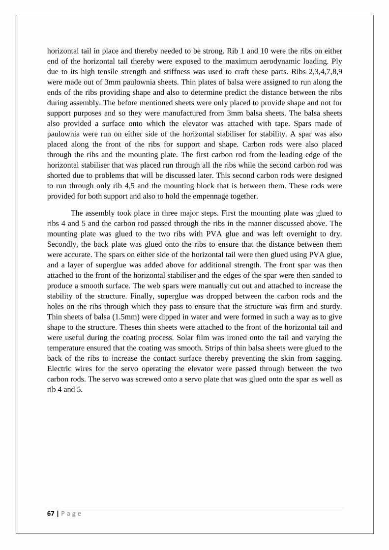
67 | P a g e
horizontal tail in place and thereby needed to be strong. Rib 1 and 10 were the ribs on either
end of the horizontal tail thereby were exposed to the maximum aerodynamic loading. Ply
due to its high tensile strength and stiffness was used to craft these parts. Ribs 2,3,4,7,8,9
were made out of 3mm paulownia sheets. Thin plates of balsa were assigned to run along the
ends of the ribs providing shape and also to determine predict the distance between the ribs
during assembly. The before mentioned sheets were only placed to provide shape and not for
support purposes and so they were manufactured from 3mm balsa sheets. The balsa sheets
also provided a surface onto which the elevator was attached with tape. Spars made of
paulownia were run on either side of the horizontal stabiliser for stability. A spar was also
placed along the front of the ribs for support and shape. Carbon rods were also placed
through the ribs and the mounting plate. The first carbon rod from the leading edge of the
horizontal stabiliser that was placed run through all the ribs while the second carbon rod was
shorted due to problems that will be discussed later. This second carbon rods were designed
to run through only rib 4,5 and the mounting block that is between them. These rods were
provided for both support and also to hold the empennage together.
The assembly took place in three major steps. First the mounting plate was glued to
ribs 4 and 5 and the carbon rod passed through the ribs in the manner discussed above. The
mounting plate was glued to the two ribs with PVA glue and was left overnight to dry.
Secondly, the back plate was glued onto the ribs to ensure that the distance between them
were accurate. The spars on either side of the horizontal tail were then glued using PVA glue,
and a layer of superglue was added above for additional strength. The front spar was then
attached to the front of the horizontal stabiliser and the edges of the spar were then sanded to
produce a smooth surface. The web spars were manually cut out and attached to increase the
stability of the structure. Finally, superglue was dropped between the carbon rods and the
holes on the ribs through which they pass to ensure that the structure was firm and sturdy.
Thin sheets of balsa (1.5mm) were dipped in water and were formed in such a way as to give
shape to the structure. Theses thin sheets were attached to the front of the horizontal tail and
were useful during the coating process. Solar film was ironed onto the tail and varying the
temperature ensured that the coating was smooth. Strips of thin balsa sheets were glued to the
back of the ribs to increase the contact surface thereby preventing the skin from sagging.
Electric wires for the servo operating the elevator were passed through between the two
carbon rods. The servo was screwed onto a servo plate that was glued onto the spar as well as
rib 4 and 5.
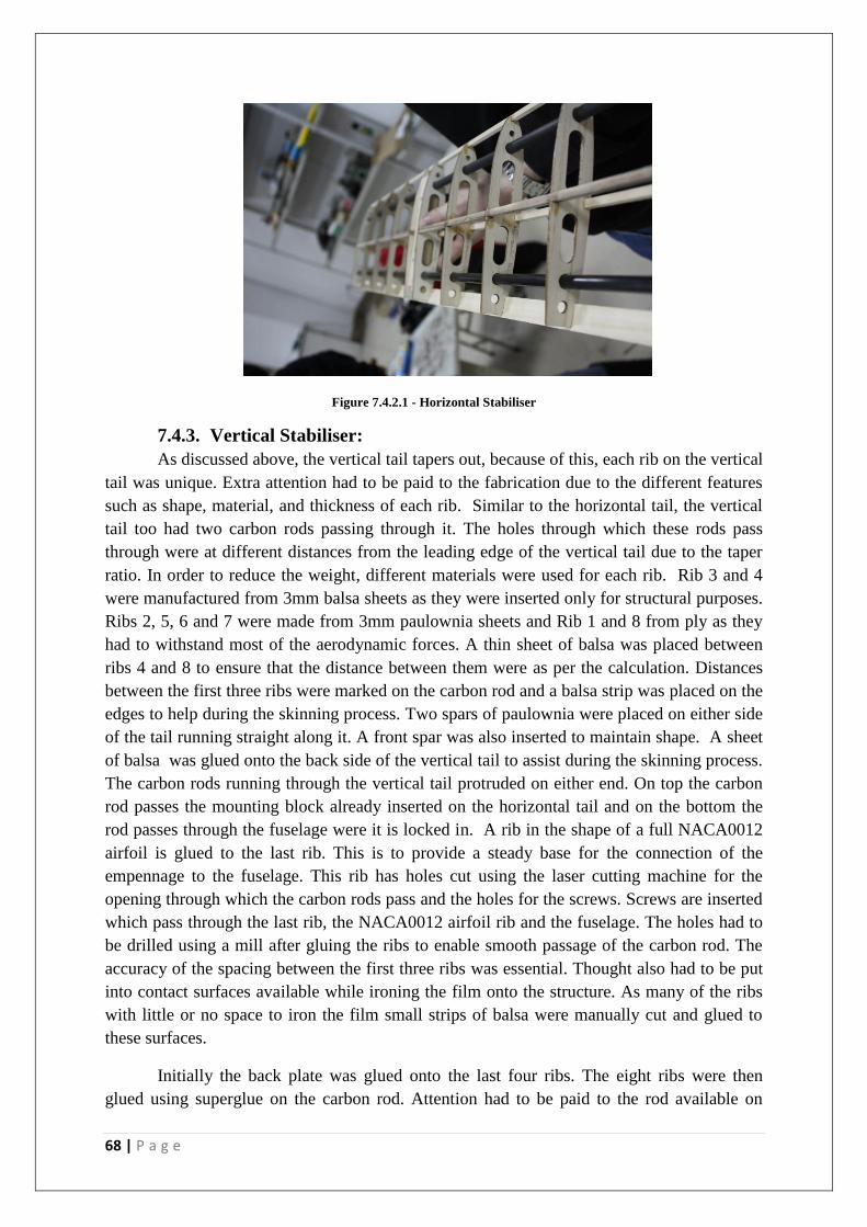
68 | P a g e
Figure 7.4.2.1 - Horizontal Stabiliser
7.4.3. Vertical Stabiliser:
As discussed above, the vertical tail tapers out, because of this, each rib on the vertical
tail was unique. Extra attention had to be paid to the fabrication due to the different features
such as shape, material, and thickness of each rib. Similar to the horizontal tail, the vertical
tail too had two carbon rods passing through it. The holes through which these rods pass
through were at different distances from the leading edge of the vertical tail due to the taper
ratio. In order to reduce the weight, different materials were used for each rib. Rib 3 and 4
were manufactured from 3mm balsa sheets as they were inserted only for structural purposes.
Ribs 2, 5, 6 and 7 were made from 3mm paulownia sheets and Rib 1 and 8 from ply as they
had to withstand most of the aerodynamic forces. A thin sheet of balsa was placed between
ribs 4 and 8 to ensure that the distance between them were as per the calculation. Distances
between the first three ribs were marked on the carbon rod and a balsa strip was placed on the
edges to help during the skinning process. Two spars of paulownia were placed on either side
of the tail running straight along it. A front spar was also inserted to maintain shape. A sheet
of balsa was glued onto the back side of the vertical tail to assist during the skinning process.
The carbon rods running through the vertical tail protruded on either end. On top the carbon
rod passes the mounting block already inserted on the horizontal tail and on the bottom the
rod passes through the fuselage were it is locked in. A rib in the shape of a full NACA0012
airfoil is glued to the last rib. This is to provide a steady base for the connection of the
empennage to the fuselage. This rib has holes cut using the laser cutting machine for the
opening through which the carbon rods pass and the holes for the screws. Screws are inserted
which pass through the last rib, the NACA0012 airfoil rib and the fuselage. The holes had to
be drilled using a mill after gluing the ribs to enable smooth passage of the carbon rod. The
accuracy of the spacing between the first three ribs was essential. Thought also had to be put
into contact surfaces available while ironing the film onto the structure. As many of the ribs
with little or no space to iron the film small strips of balsa were manually cut and glued to
these surfaces.
Initially the back plate was glued onto the last four ribs. The eight ribs were then
glued using superglue on the carbon rod. Attention had to be paid to the rod available on

69 | P a g e
either end for the connection of the vertical tail to the horizontal tail and fuselage respectively.
The spars were attached using AB glue on both sides and front of the vertical tail. A thin
sheet of balsa was attached to the back of the last 5 ribs to provide shape. The servo plate was
glued to rib 2 and 3 (from the bottom) and to the top spar to guarantee its contact with
maximum available surfaces. The final structure was sanded to provide a smooth finish.
1.5mm balsa sheets, whose malleability was increased by first dipping in water was used and
then held in place while they dried to the shape. This skin provided shape and came in handy
whilst ironing the solar film onto the structure. Wires were run through the carbon rod to the
servo attached to the horizontal tail. Wires for the operation of the rudder were passed
through the gap cut out in the ribs to reduce weight.
7.4.4. Attachment:
Adhesives such as AB glue, PVA glue and superglue were the main choices for the
attaching the parts together. Locking systems on plates placed in front were used in the
elevator and rudder to hold the structures together. A similar locking system was also used in
attaching the two parts of the mounting block together.
The attachment of the vertical to the horizontal was critical as top most rib on the
vertical tail had to sit flush between the middle two ribs on the horizontal stabiliser. After
several debates, carbon rods were used for this purpose due to their strength and stiffness.
The carbon rods running through the horizontal stabiliser not only held the structure straight
and prevented it from bending, but also enabled it to withstand dynamic loads. The carbon
rods on the vertical tail ensured that it sat vertical on the fuselage. The mounting block held
the whole structure in place. The rudder and elevator were taped onto the vertical and
horizontal stabiliser respectively. The front plate on the rudder and elevator and the back
plate on the vertical and horizontal tail provided contact surface for the clear tape. The
control surfaces were first deflected downwards to its maximum and taped on the top side
and vice versa were done on the bottom side of the control surfaces.
7.4.5. Problems:
The key problem encountered during the fabrication of the empennage was with the
connecting mounting block. As briefly discussed above, the design of the mounting block had
to be revised in order to manufacture a stable empennage. The error was noticed after
constructing the horizontal tail which included the mounting block. A geometric twist was
noticed when it was mounted onto the vertical tail. Geometric twist of wing is the actual
change in the airfoil angle of incidence which is usually measured with respect to the root
airfoil. When closely inspected it was noticed that the carbon rods which ran through all the
ribs were slanting. The holes through which the carbon rods on the vertical tail passes
through were cut were done using the laser cutting machine while the hole for the carbon rods
on the horizontal to pass was drilled using an electronic mill after the layers were glued
together. The hole drilled was not straight thereby causing the rods passes through it to be
inclined at an angle as well.
Two design changes were made to fix this error. First the mounting block was divided
into two blocks which were joined together by a locking system as afore mentioned. This

70 | P a g e
enabled the holes for both the sets of the carbon rods to be cut out using the laser cutting
machine which ensured that when the layers were glued the holes aligned perfectly. The
second design change made was to the carbon rod placed second from the leading edge of the
horizontal rail. Initially this rod ran through all the ribs, it was shortened to decreases the
chances of there being a twist on the tail. The new design saw the carbon rod running through
rib 5, 6 and the mounting block. Web spars were added for extra strength.
7.5. Control Surface Fabrication
7.5.1. Elevator:
The elevator being 0.84m had to be constructed as two different sections. The plate
with the cut-outs which proved as a guideline for the placement of the elevator ribs were first
glued on followed by the two paulownias spars that provided stability and shape. The above
mention plate that was glued to the front of the elevator also held the servo horn which acted
as the connection between the servo placed on the vertical tail and the elevator. A thin strip of
paulownia was also glued to the front of the elevator at an angle with a cut out to lock in the
ribs and also provide shape. 1.5mm thick balsa strips were attached to the ends of the elevator
ribs to provided shape during the process of ironing the film onto the elevator.
7.5.2. Rudder:
The fabrication of the rudder was very similar to that of the elevator, the difference
being that the rudder consisted of 4 ribs and were longer in length compared to the ribs on the
elevator. Back plate made from thin balsa sheets were also glued onto either side of the
rudder at the back to provide shape. Plates were also placed at a 40 degree angle on the front
of the rudder to assist during the application of the film.
Figure 7.5.2.1 – Rudder
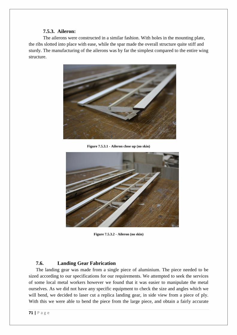
71 | P a g e
7.5.3. Aileron:
The ailerons were constructed in a similar fashion. With holes in the mounting plate,
the ribs slotted into place with ease, while the spar made the overall structure quite stiff and
sturdy. The manufacturing of the ailerons was by far the simplest compared to the entire wing
structure.
Figure 7.5.3.1 - Aileron close up (no skin)
Figure 7.5.3.2 - Aileron (no skin)
7.6. Landing Gear Fabrication
The landing gear was made from a single piece of aluminium. The piece needed to be
sized according to our specifications for our requirements. We attempted to seek the services
of some local metal workers however we found that it was easier to manipulate the metal
ourselves. As we did not have any specific equipment to check the size and angles which we
will bend, we decided to laser cut a replica landing gear, in side view from a piece of ply.
With this we were able to bend the piece from the large piece, and obtain a fairly accurate
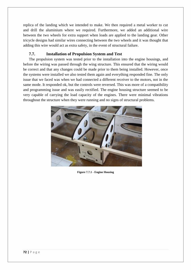
72 | P a g e
replica of the landing which we intended to make. We then required a metal worker to cut
and drill the aluminium where we required. Furthermore, we added an additional wire
between the two wheels for extra support when loads are applied to the landing gear. Other
tricycle designs had similar wires connecting between the two wheels and it was thought that
adding this wire would act as extra safety, in the event of structural failure.
7.7. Installation of Propulsion System and Test
The propulsion system was tested prior to the installation into the engine housings, and
before the wiring was passed through the wing structure. This ensured that the wiring would
be correct and that any changes could be made prior to them being installed. However, once
the systems were installed we also tested them again and everything responded fine. The only
issue that we faced was when we had connected a different receiver to the motors, not in the
same mode. It responded ok, but the controls were reversed. This was more of a compatibility
and programming issue and was easily rectified. The engine housing structure seemed to be
very capable of carrying the load capacity of the engines. There were minimal vibrations
throughout the structure when they were running and no signs of structural problems.
Figure 7.7.1 - Engine Housing
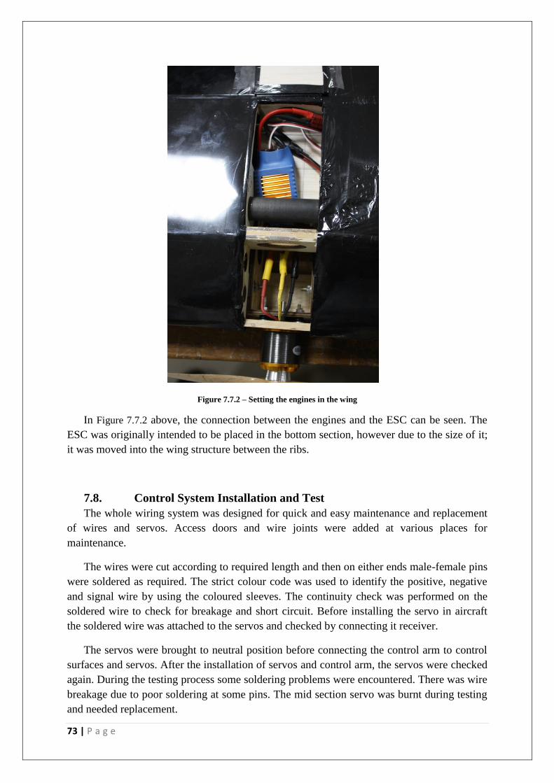
73 | P a g e
Figure 7.7.2 – Setting the engines in the wing
In Figure 7.7.2 above, the connection between the engines and the ESC can be seen. The
ESC was originally intended to be placed in the bottom section, however due to the size of it;
it was moved into the wing structure between the ribs.
7.8. Control System Installation and Test
The whole wiring system was designed for quick and easy maintenance and replacement
of wires and servos. Access doors and wire joints were added at various places for
maintenance.
The wires were cut according to required length and then on either ends male-female pins
were soldered as required. The strict colour code was used to identify the positive, negative
and signal wire by using the coloured sleeves. The continuity check was performed on the
soldered wire to check for breakage and short circuit. Before installing the servo in aircraft
the soldered wire was attached to the servos and checked by connecting it receiver.
The servos were brought to neutral position before connecting the control arm to control
surfaces and servos. After the installation of servos and control arm, the servos were checked
again. During the testing process some soldering problems were encountered. There was wire
breakage due to poor soldering at some pins. The mid section servo was burnt during testing
and needed replacement.
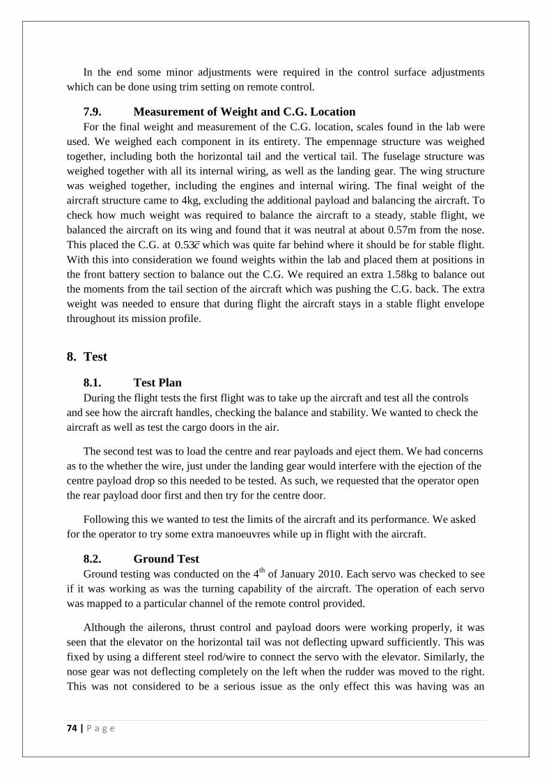
74 | P a g e
In the end some minor adjustments were required in the control surface adjustments
which can be done using trim setting on remote control.
7.9. Measurement of Weight and C.G. Location
For the final weight and measurement of the C.G. location, scales found in the lab were
used. We weighed each component in its entirety. The empennage structure was weighed
together, including both the horizontal tail and the vertical tail. The fuselage structure was
weighed together with all its internal wiring, as well as the landing gear. The wing structure
was weighed together, including the engines and internal wiring. The final weight of the
aircraft structure came to 4kg, excluding the additional payload and balancing the aircraft. To
check how much weight was required to balance the aircraft to a steady, stable flight, we
balanced the aircraft on its wing and found that it was neutral at about 0.57m from the nose.
This placed the C.G. at 0.53c which was quite far behind where it should be for stable flight.
With this into consideration we found weights within the lab and placed them at positions in
the front battery section to balance out the C.G. We required an extra 1.58kg to balance out
the moments from the tail section of the aircraft which was pushing the C.G. back. The extra
weight was needed to ensure that during flight the aircraft stays in a stable flight envelope
throughout its mission profile.
8. Test
8.1. Test Plan
During the flight tests the first flight was to take up the aircraft and test all the controls
and see how the aircraft handles, checking the balance and stability. We wanted to check the
aircraft as well as test the cargo doors in the air.
The second test was to load the centre and rear payloads and eject them. We had concerns
as to the whether the wire, just under the landing gear would interfere with the ejection of the
centre payload drop so this needed to be tested. As such, we requested that the operator open
the rear payload door first and then try for the centre door.
Following this we wanted to test the limits of the aircraft and its performance. We asked
for the operator to try some extra manoeuvres while up in flight with the aircraft.
8.2. Ground Test
Ground testing was conducted on the 4th
of January 2010. Each servo was checked to see
if it was working as was the turning capability of the aircraft. The operation of each servo
was mapped to a particular channel of the remote control provided.
Although the ailerons, thrust control and payload doors were working properly, it was
seen that the elevator on the horizontal tail was not deflecting upward sufficiently. This was
fixed by using a different steel rod/wire to connect the servo with the elevator. Similarly, the
nose gear was not deflecting completely on the left when the rudder was moved to the right.
This was not considered to be a serious issue as the only effect this was having was an
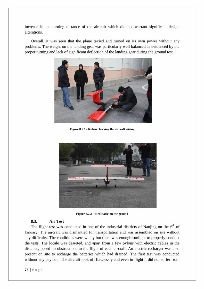
75 | P a g e
increase in the turning distance of the aircraft which did not warrant significant design
alterations.
Overall, it was seen that the plane taxied and turned on its own power without any
problems. The weight on the landing gear was particularly well balanced as evidenced by the
proper turning and lack of significant deflection of the landing gear during the ground test.
Figure 8.2.1 - Kelvin checking the aircraft wiring
Figure 8.2.2 - 'Red Back' on the ground
8.3. Air Test
The flight test was conducted in one of the industrial districts of Nanjing on the 6th
of
January. The aircraft was dismantled for transportation and was assembled on site without
any difficulty. The conditions were windy but there was enough sunlight to properly conduct
the tests. The locale was deserted, and apart from a few pylons with electric cables in the
distance, posed no obstructions to the flight of each aircraft. An electric recharger was also
present on site to recharge the batteries which had drained. The first test was conducted
without any payload. The aircraft took off flawlessly and even in flight it did not suffer from

76 | P a g e
a lot of instability. During the landing approach, the power to the engines was turned off. The
aircraft descended smoothly and accomplished an unpowered landing without mishap. The
landing gear was seen to hold the weight smoothly without buckling.
Figure 8.3.1 - 'Red Back' Taking off
Figure 8.3.2 - 'Red Back' landing after madden flight
In the second test, the payload was added in both the rear bay and under the wings.
Although this shifted the centre of gravity, the new location was still within the quarter chord
of the wing and the flight performance of the aircraft did not suffer noticeably.
The ejection of the payload was done from a significant height. The payload from the rear
bay was dropped first from an estimated height of about 70 m. The parachute opened
properly a certain distance above the ground (approximately 10 m) and the box descended
safely. Upon inspection it was found that the contents of the box were unharmed. The second
payload was released from a slightly higher altitude (approximately 80 m). Although the two
parachutes opened almost immediately after release, the string got tangled into the wire
connecting the wheels in the main landing gear. This had not been foreseen as a significant

77 | P a g e
concern during the aircraft’s manufacturing and the aircraft landed with the two parachutes
dragging behind the landing gear.
Figure 8.3.3 - Centre payload parachute got caught on the landing gear wire
In the third flight, the wire connecting the wheels of the main landing gear was removed.
This had not been a part of the original design and was only attached during manufacturing to
further increase the strength of the landing gear. The same mission profile was used as the
last test. As before, the rear payload was released without incident. The payload under the
wing was released from an altitude of approximately 100m and about 200m away from the
runway. The two parachutes deployed perfectly and the contents of the payload box were
undamaged. It should be noted that the shift in centre of gravity in the last two flights after
the release of payload did not hamper the performance and stability of the aircraft noticeably.
It was decided by the team do a touch and go landing after the payload had been released
successfully during the third flight test. Although not part of the original mission profile, it
was thought that the airframe and landing gear could accomplish such a task without any
problems. This was indeed seen to be the case and after doing a touchdown unpowered, the
aircraft was able to take off successfully at full throttle after a very small distance. The
landing gear held firm and was not damaged during this stage. On its final landing approach,
due to a slight error in the pilot’s judgment, the aircraft came in at a roll on the right. Upon
landing this chipped off a bit of the right propeller and pushed the right landing gear slightly
into the fuselage. However, successful repairs were accomplished in the field using glue and
pieces of wood and the aircraft was airworthy again.
The aircraft accomplished all of its design objectives and in the case of the hit and go
landing performed beyond its design criteria and expectations, rendering this project a
success.
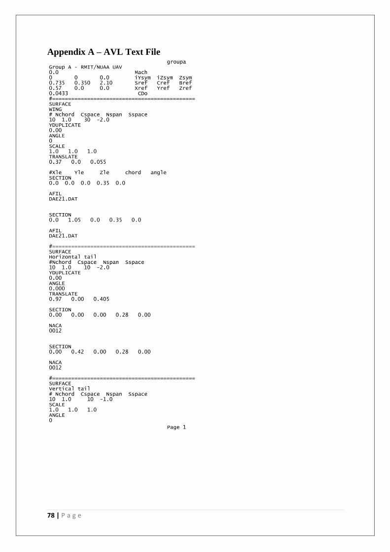
78 | P a g e
Appendix A – AVL Text File
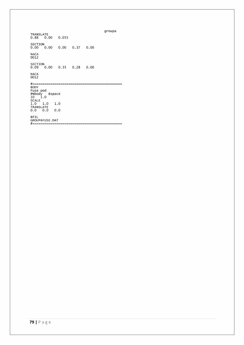
79 | P a g e
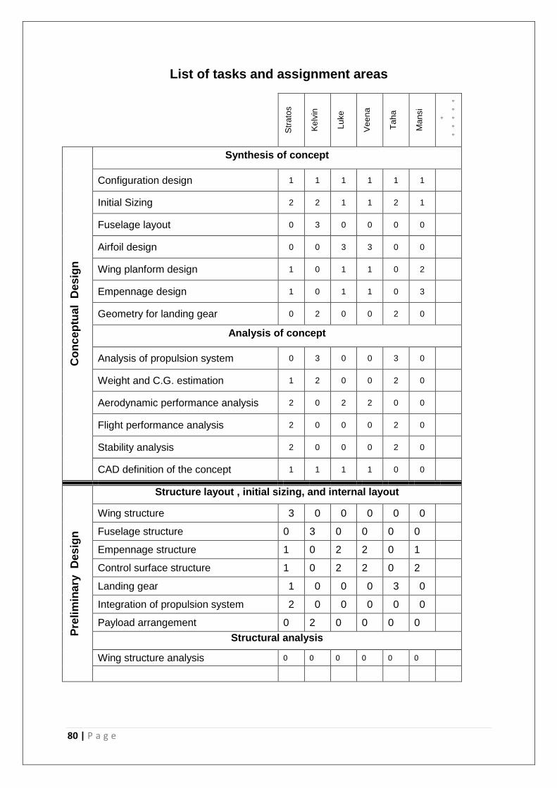
80 | P a g e
List of tasks and assignment areas
Str
ato
s
K
elv
in
Lu
ke
Ve
en
a
Ta
ha
Ma
nsi
。。。。。
。
Co
nc
ep
tual
Desig
n
Synthesis of concept
Configuration design 1 1 1 1 1 1
Initial Sizing 2 2 1 1 2 1
Fuselage layout 0 3 0 0 0 0
Airfoil design 0 0 3 3 0 0
Wing planform design 1 0 1 1 0 2
Empennage design 1 0 1 1 0 3
Geometry for landing gear 0 2 0 0 2 0
Analysis of concept
Analysis of propulsion system 0 3 0 0 3 0
Weight and C.G. estimation 1 2 0 0 2 0
Aerodynamic performance analysis 2 0 2 2 0 0
Flight performance analysis 2 0 0 0 2 0
Stability analysis 2 0 0 0 2 0
CAD definition of the concept 1 1 1 1 0 0
Pre
lim
ina
ry
De
sig
n
Structure layout , initial sizing, and internal layout
Wing structure 3 0 0 0 0 0
Fuselage structure 0 3 0 0 0 0
Empennage structure 1 0 2 2 0 1
Control surface structure 1 0 2 2 0 2
Landing gear 1 0 0 0 3 0
Integration of propulsion system 2 0 0 0 0 0
Payload arrangement 0 2 0 0 0 0
Structural analysis
Wing structure analysis 0 0 0 0 0 0
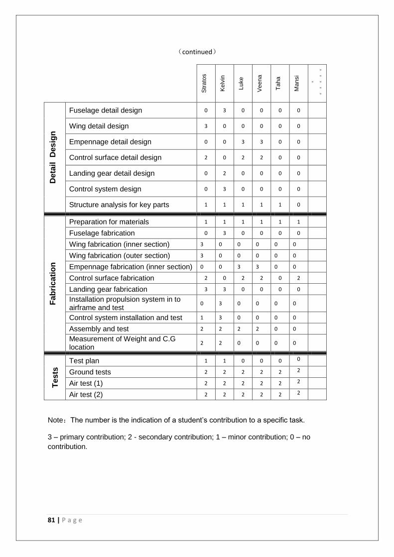
81 | P a g e
(continued)
Str
ato
s
K
elv
in
Lu
ke
Ve
en
a
Ta
ha
Ma
nsi
。。。。。
。
Deta
il
Des
ign
Fuselage detail design 0 3 0 0 0 0
Wing detail design 3 0 0 0 0 0
Empennage detail design 0 0 3 3 0 0
Control surface detail design 2 0 2 2 0 0
Landing gear detail design 0 2 0 0 0 0
Control system design 0 3 0 0 0 0
Structure analysis for key parts 1 1 1 1 1 0
Fab
ric
ati
on
Preparation for materials 1 1 1 1 1 1
Fuselage fabrication 0 3 0 0 0 0
Wing fabrication (inner section) 3 0 0 0 0 0
Wing fabrication (outer section) 3 0 0 0 0 0
Empennage fabrication (inner section) 0 0 3 3 0 0
Control surface fabrication 2 0 2 2 0 2
Landing gear fabrication 3 3 0 0 0 0
Installation propulsion system in to airframe and test
0 3 0 0 0 0
Control system installation and test 1 3 0 0 0 0
Assembly and test 2 2 2 2 0 0
Measurement of Weight and C.G location
2 2 0 0 0 0
Te
sts
Test plan 1 1 0 0 0 0
Ground tests 2 2 2 2 2 2
Air test (1) 2 2 2 2 2 2
Air test (2) 2 2 2 2 2 2
Note:The number is the indication of a student’s contribution to a specific task.
3 – primary contribution; 2 - secondary contribution; 1 – minor contribution; 0 – no
contribution.


![INDEX [gibbssmithcovers.com]gibbssmithcovers.com/GS-S2020-Catalog-Back.pdf · Architectural Guidebook to Brooklyn, An, 70 Architectural Guidebook to Los Angeles, An, 151 Architectural](https://img.pdfslide.net/doc/110x75/5f0e78d17e708231d43f6942/index-architectural-guidebook-to-brooklyn-an-70-architectural-guidebook-to.jpg)