Embed Size (px)
Citation preview
Rev. E 02-12-07 1 P/N 350062
EQ Series® Strainer Pot Owner's Manual
Pentair Water Pool and Spa, Inc.1620 Hawkins Ave., Sanford, NC 27330 • (919) 566-800010951 West Los Angeles Ave., Moorpark, CA 93021 • (800) 553-5000www.pentairpool.com and starite.com
IMPORTANT SAFETY INSTRUCTIONSREAD AND FOLLOW ALL INSTRUCTIONS
SAVE THESE INSTRUCTIONS
Read and follow all warning notices and instructions accompanying this product before installing.Failure to follow safety warnings and instructions can result in severe injury, death, or property damage.Call (800) 831-7133 (US) for additional free copies of these instructions.
WARNING
Attention Installer.
This manual contains important information about the installation, operation and safe use of thisproduct. This information should be given to the owner/operator of this equipment.
Important Notice
Table of Contents
SECTION I. GENERAL INFORMATION .............................................................................................................. 2
SECTION II. MECHANICAL INSTALLATION AND PRESSURE TESTING ........................................................... 2
SECTION III. INITIAL OPERATION ...................................................................................................................... 6
SECTION IV. CLEANING THE STRAINER BASKET ............................................................................................ 6
SECTION V. REPLACEMENT PARTS ................................................................................................................ 8
SECTION VI. STRAINER POT ASSEMBLY TECHNICAL DATA ....................................................................... 9-10
TECHNICAL SUPPORT ................................................................................................................ 11
CE marking only applies to 50 Hz models:EQK300, EQK500, EQK750, and EQK1000.
P/N 350062 2 Rev. E 02-12-07
SECTION I. GENERAL INFORMATION
This product is intended for use in swimming pool applications only. It may be mounted directly to a Pentair Pool ProductsEQ Series pump. This will provide filtration of debris that could damage the pump and will allow the pump to be self-primingin installations up to 10 feet. The exact height at which a pump can prime depends on many installation and environmentalfactors.
The EQ Strainer Pot Assembly may also be mounted as a separate unit in the suction line of a circulation system.
CAUTIONIf this product is to be attached to an EQ Series Pump you also must read and follow all warning notices andinstructions in the pump manual.
SECTION II. MECHANICAL INSTALLATION AND PRESSURE TESTING
A. MECHANICAL INSTALLATION
1. Carefully remove the strainer pot assembly from its shipping package.
2. Determine the installation location of the strainer pot assembly. Ensure that adequate space and lighting isprovided for routine maintenance.
3. It is good practice to install a valve on the suction line before this unit and on the return line after the pump sothat both items can be isolated for routine maintenance.
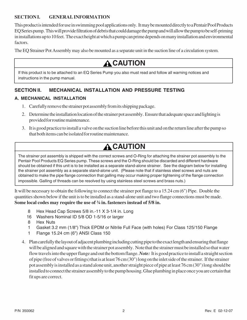
CAUTIONThe strainer pot assembly is shipped with the correct screws and O-Ring for attaching the strainer pot assembly to thePentair Pool Products EQ Series pump. These screws and the O-Ring should be discarded and different hardwareshould be obtained if this unit is to be installed as a separate stand-alone strainer. See the diagram below for installingthe strainer pot assembly as a separate stand-alone unit. (Please note that if stainless steel screws and nuts areobtained to make the pipe flange connection that galling may occur making proper tightening of the flange connectionimpossible. Galling of threads can be resolved by using stainless steel screws and brass nuts.)
It will be necessary to obtain the following to connect the strainer pot flange to a 15.24 cm (6") Pipe. Double thequantities shown below if the unit is to be installed as a stand-alone unit and two flange connections must be made.Some local codes may require the use of ¾ in. fasteners instead of 5/8 in.
8 Hex Head Cap Screws 5/8 in.-11 X 3-1/4 in. Long16 Washers Nominal ID 5/8 OD 1-5/16 or larger8 Hex Nuts1 Gasket 3.2 mm (1/8") Thick EPDM or Nitrile Full Face (with holes) For Class 125/150 Flange1 Flange 15.24 cm (6") ANSI Class 150
4. Plan carefully the layout of adjacent plumbing including cutting pipe to the exact length and ensuring that flangewill be aligned and square with the strainer pot assembly. Note that the strainer must be installed so that waterflow travels into the upper flange and out the bottom flange. Note: It is good practice to install a straight sectionof pipe (free of valves or fittings) that is at least 76 cm (30") long on the inlet side of the strainer. If the strainerpot assembly is installed as a stand alone unit, another straight piece of pipe at least 76 cm (30") long should beinstalled to connect the strainer assembly to the pump housing. Glue plumbing in place once you are certain thatfit ups are correct.
Rev. E 02-12-07 3 P/N 350062
5. Ensure that the flange gasket is properlypositioned between the strainer potflange and the top flange connection.Use only high quality, full diameter,3.2 mm (1/8") thick gaskets with holesfor the bolts to pass through. It may benecessary to hold the gasket in place witheither silicone or two or three drops ofcyanoacrylate (super glue). Do not useany other grease or glue as they maycontain chemicals that could attack theplastic material.
6. Install the flange screws, washers andnuts hand tight on the first flangeconnection as shown in the diagram.
7. Repeat steps 4, 5 and 6 for the lower flange connection unless the strainer is directly attached to a Pentair PoolProducts EQ Series pump.
8. Inspect both flange connection(s) to ensure that the flanges of the strainer pot and the connection flanges are inline and that the faces are parallel. Take any corrective action to properly align flanges before tightening theflange screws to the required torque.
CAUTIONUse large diameter flat washers (at least 1-5/16 in. outer diameter) between the hex nut and the strainer pot assemblyflanges to properly distribute the clamping forces on the flanges. Tighten the flange bolts to 27.1 newton meter (20 ft-lb)unless otherwise specified by the flange manufacturer. If it is not possible to use a torque wrench then care should betaken not to over tighten the flange bolts. Failure to follow the above instructions can result in damaging the strainer potflanges.
CAUTIONSuction and discharge piping must be supported by an appropriate system of supports or hangers. Inadequatelysupported pipe can cause excessive loads to be transmitted to the strainer pot assembly resulting in a structural failurethat could result in flooding and property damage.
B. PRESSURE TESTING
Certain local codes require that the circulation system be pressure tested with a proof pressure before beingcommissioned into service or before allowing construction to progress to the next stage.
WARNINGThis product is intended to operate on the suction side of the pump and must not be installed on the pressure side of acirculation system. Extreme caution should be taken when applying pressure to this product during a system pressuretest as this product has a lower pressure rating than other components in the system. Exceeding the pressure ortemperature rating during the pressure test can result in a structural failure. A structural failure of the strainer potassembly can cause the instantaneous release of energy causing failed components to be accelerated to high velocitiesand to travel distances of 30.5 m (100 feet) or more. These components could cause severe personal injury or death ifthey were to strike a person.
Figure 1.
HEX NUT 5/8-11
5/8 ID X 1-5/16 MIN. ODFLAT WASHER
70 DURO NITRILE OR EPDM1/8" THICK GASKET
5/8" ID X 1-5/16 MIN. ODFLAT WASHER
HEX HEAD CAP SCREW5/8-11 X 3-1/4"
6" ANSI CLASS 150 FLANGE
P/N 350062 4 Rev. E 02-12-07
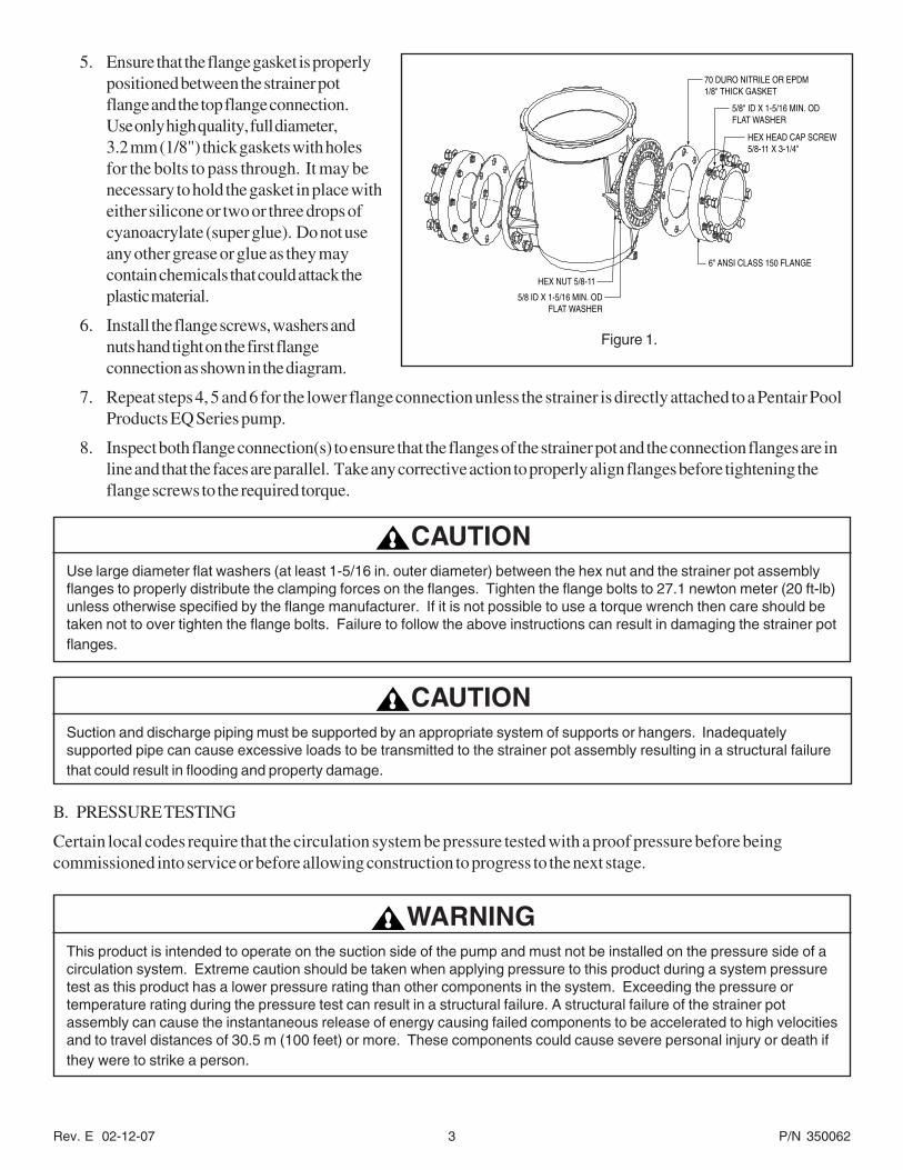
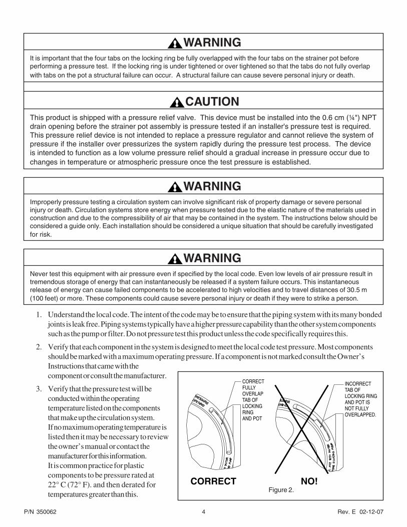
WARNINGIt is important that the four tabs on the locking ring be fully overlapped with the four tabs on the strainer pot beforeperforming a pressure test. If the locking ring is under tightened or over tightened so that the tabs do not fully overlapwith tabs on the pot a structural failure can occur. A structural failure can cause severe personal injury or death.
CAUTIONThis product is shipped with a pressure relief valve. This device must be installed into the 0.6 cm (¼") NPTdrain opening before the strainer pot assembly is pressure tested if an installer's pressure test is required.This pressure relief device is not intended to replace a pressure regulator and cannot relieve the system ofpressure if the installer over pressurizes the system rapidly during the pressure test process. The deviceis intended to function as a low volume pressure relief should a gradual increase in pressure occur due tochanges in temperature or atmospheric pressure once the test pressure is established.
WARNINGImproperly pressure testing a circulation system can involve significant risk of property damage or severe personalinjury or death. Circulation systems store energy when pressure tested due to the elastic nature of the materials used inconstruction and due to the compressibility of air that may be contained in the system. The instructions below should beconsidered a guide only. Each installation should be considered a unique situation that should be carefully investigatedfor risk.
WARNINGNever test this equipment with air pressure even if specified by the local code. Even low levels of air pressure result intremendous storage of energy that can instantaneously be released if a system failure occurs. This instantaneousrelease of energy can cause failed components to be accelerated to high velocities and to travel distances of 30.5 m(100 feet) or more. These components could cause severe personal injury or death if they were to strike a person.
1. Understand the local code. The intent of the code may be to ensure that the piping system with its many bondedjoints is leak free. Piping systems typically have a higher pressure capability than the other system componentssuch as the pump or filter. Do not pressure test this product unless the code specifically requires this.
2. Verify that each component in the system is designed to meet the local code test pressure. Most componentsshould be marked with a maximum operating pressure. If a component is not marked consult the Owner’sInstructions that came with thecomponent or consult the manufacturer.
3. Verify that the pressure test will beconducted within the operatingtemperature listed on the componentsthat make up the circulation system.If no maximum operating temperature islisted then it may be necessary to reviewthe owner’s manual or contact themanufacturer for this information.It is common practice for plasticcomponents to be pressure rated at22° C (72° F). and then derated fortemperatures greater than this.
CORRECTFULLYOVERLAPTAB OFLOCKINGRINGAND POT
INCORRECTTAB OFLOCKING RINGAND POT ISNOT FULLYOVERLAPPED.
CORRECT NO!Figure 2.
Rev. E 02-12-07 5 P/N 350062
4. Use only a high quality pressure gage that is certified to be accurate for the pressure for which the test is goingto be conducted. Do not rely on the pressure gage included with the filtration system as it may not be sufficientlyaccurate to conduct a pressure test for the system. Please note that the pressure in the system will varydepending on where the pressure is taken due to the weight of the water.
5. Ensure that all air will be evacuated from the system when the water pressure is applied to the system. This willrequire that all air bleeders on any equipment are open. It also may be necessary to remove some lids or coverson system equipment such as the pump strainer lid to prevent air from being trapped in the system. In addition,there may be other areas of the circulation system where air may be trapped. Do not connect water pressure tothe system until you are certain that air will be totally evacuated.
6. Determine the appropriate location in the system to apply the test water pressure. Consider the place in thesystem that will best ensure that all air will be displaced when water is introduced.
WARNINGNever exceed the maximum operating pressure or temperature limits of the system components. Ensure that pressureshigher than those required in the pressure test cannot inadvertently be applied to the circulation system. This mayrequire the use of a pressure regulator between the water supply and the circulation system.
Changes in temperature or barometric pressure can cause the internal test pressure to increase or decrease over timeonce the system is isolated. A pressure relief device should be installed that would prevent the pressure from exceedingthe intended test pressure. Exceeding these limits could result in a component failing under pressure. Thisinstantaneous release of energy can cause failed components to be accelerated to high velocities and to traveldistances of 30.5 m (100 feet) or more. These components could cause severe personal injury or death if they were tostrike a person.
7. Slowly apply the water pressure and allow the water to flow out all of the openings intended for air to escape.Close the openings beginning at the lowest level first and progressing to the highest level. Do not close anyopening until you are sure that air is completely out of that part of the system.
8. Allow the pressure to slowly build once all of the air openings are closed. Close the valve between the watersupply and circulation system to isolate the system from the supply pressure.
9. Monitor the system pressure for a few minutes to ensure that it is stabilized.
WARNINGDue to the potential risk that can be involved it is recommended that the pressure test be kept to the minimum timerequired by the local code. Do not allow people to work around the system when the circulation system is underpressure test. Post appropriate warning signs and establish a barrier around the pressurized equipment. If the equipmentis located in an equipment room, lock the door and post a warning sign.
Never attempt to adjust any closures or lids or attempt to remove or tighten bolts when the system is pressurized.These actions can result in a separation or failure of system components. This instantaneous release of energy cancause components to be accelerated to high velocities and to travel distances of 30.5 m (100 feet) or more. Thesecomponents could cause severe personal injury or death if they were to strike a person.
10. It is normal for the test pressure to drift down slightly during the first few minutes as the circulation systemexpands under pressure.
11. If the system pressure continues to fall, then bleed off the remaining water pressure in the circulation system andinspect the system for leaks. Look for water on the floor and feel around joints for moisture.
12. Ensure the system is not under pressure before attempting any system adjustments or repairs.
13. Repeat the pressurization sequence once the system leaks have been corrected.
P/N 350062 6 Rev. E 02-12-07
SECTION III. INITIAL OPERATION
Verify that the following tasks are completed before energizing the circulation pump.
1. Make sure the O-Ring is on drain plug and that drain plug is tightened hand tight.
2. Fill strainer pot with as much water as it will hold.
3. Position basket correctly in pot.
4. Inspect the O-Ring in the lid to make sure that it is clean and properly positioned in the groove.
5. Install the lid into the strainer pot so that the tabs on the lid overlay the tabs on the strainer pot.
6. Secure lid in place by tightening the locking ring hand tight only.
WARNINGThe strainer pot may be at a pressure that is higher or lower than the atmospheric pressure. Always open the drain plugon the strainer pot and allow for the pressure to equalize before removing the locking ring. Attempting to remove thelocking ring before the pressure is equalized may result in a rapid exchange of pressure. This instantaneous release ofenergy can cause components to be accelerated to high velocities and to travel distances of 30.5 m (100 feet) or more.These components could cause severe personal injury or death if they were to strike a person.
WARNINGDO NOT open the strainer pot if pump fails to prime or if pump has been operating without water in the strainer pot.Pumps operated in these circumstances may experience a build up of vapor pressure and may contain scalding hotwater. Opening the strainer pot may cause serious personal injury. In order to avoid personal injury make sure thestrainer pot temperature has cooled to room temperature. Carefully remove the drain plug on the strainer pot and allowthe pressure to equalize before removing the locking ring.
SECTION IV. CLEANING OF THE STRAINER BASKET
1. The pump is designed to be maintenance free with the exception of requiring a periodic cleaning of the strainerbasket.
2. A routine inspection should be done by visually looking through strainer lid for debris while the pump is inoperation. The strainer basket should be cleaned when approximately 25 % blocked. Allowing the strainerbasket to become excessively blocked will diminish water flow, reduce pump efficiency, cause cavitation andmay damage the basket or other pump components.
3. Disconnect power to the pump before cleaning the basket.
4. Close isolation valves on the suction and discharge lines if necessary to prevent flooding.
WARNINGThe strainer pot may be at a pressure that is higher or lower than the atmospheric pressure. Always open the drain plugon the strainer pot and allow for the pressure to equalize before removing the locking ring. Attempting to remove thelocking ring before the pressure is equalized may result in a rapid exchange of pressure. This instantaneous release ofenergy can cause components to be accelerated to high velocities and to travel distances of 30.5 m (100 feet) or more.These components could cause severe personal injury or death if they were to strike a person.
Rev. E 02-12-07 7 P/N 350062
WARNINGIf the pump has been energized for a period greater than 45 minutes without water flowing through the pump for anyreason, the water in the strainer pot may be hot. Attempting to remove the locking ring without removing the drain plugin the pot and allowing the pressure to equalize may result in the hot water rapidly escaping and causing severepersonal injury. To reduce the risk of being injured by hot or scalding water, allow the strainer pot to cool to the ambienttemperature before removing the drain plug.
5. Open the drain plug in the strainer pot and allow the pressure to completely stabilize.
6. Remove the locking ring and the clear lid from the strainer pot.
7. Remove the basket and dispose of the debris. Use a water hose and soft brush to remove debris blocking theopenings in the basket if required.
8. Replace the basket making sure it is properly oriented.
9. Replace the lid, by aligning the four tabs with the tabs on the strainer pot and making sure the O-ring is cleanand is properly located in the groove of the lid.
10. Secure the lid in place by tightening the locking ring hand tight only. Do not over tighten the locking ring as thatwill make removal difficult.
WARNINGIt is recommended that only water and a soft cloth be used to clean the lid and other pump components. Cleaners maycontain chemicals that could damage or weaken pump components causing them to fail and allowing an instantaneousrelease of energy. This instantaneous release of energy can cause components to be accelerated to high velocities andto travel distances of 30.5 m (100 feet) or more. These components could cause severe personal injury or death if theywere to strike a person.
P/N 350062 8 Rev. E 02-12-07
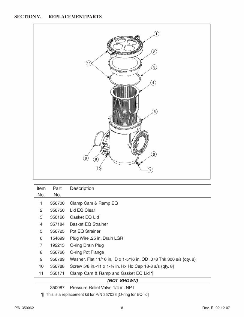
SECTION V. REPLACEMENT PARTS
Item Part DescriptionNo. No.
1 356700 Clamp Cam & Ramp EQ
2 356750 Lid EQ Clear
3 350166 Gasket EQ Lid
4 357184 Basket EQ Strainer
5 356725 Pot EQ Strainer
6 154699 Plug Wire .25 in. Drain LGR
7 192215 O-ring Drain Plug
8 356766 O-ring Pot Flange
9 356789 Washer, Flat 11/16 in. ID x 1-5/16 in. OD .078 Thk 300 s/s {qty. 8}
10 356788 Screw 5/8 in.-11 x 1-¾ in. Hx Hd Cap 18-8 s/s {qty. 8}
11 350171 Clamp Cam & Ramp and Gasket EQ Lid 
(NOT SHOWN)
350087 Pressure Relief Valve 1/4 in. NPT
¶ This is a replacement kit for P/N 357038 [O-ring for EQ lid]
8 9
10 7
6
5
4
3
2
1
11
Rev. E 02-12-07 9 P/N 350062
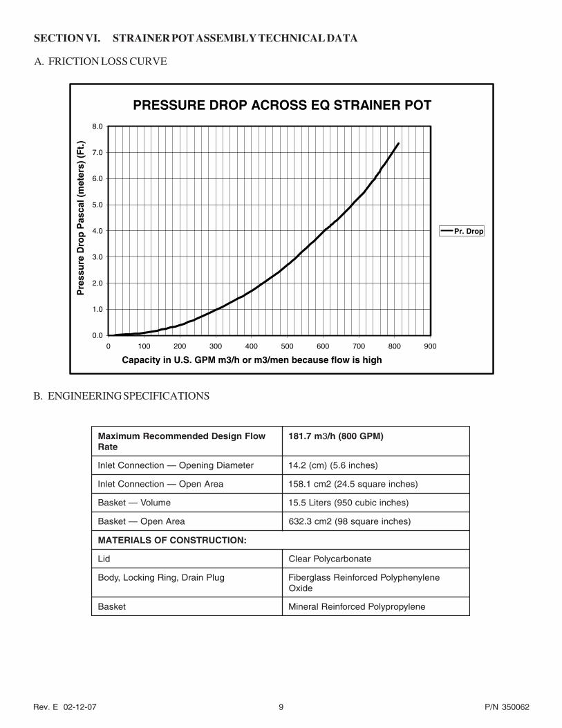
SECTION VI. STRAINER POT ASSEMBLY TECHNICAL DATA
A. FRICTION LOSS CURVE
B. ENGINEERING SPECIFICATIONS
wolFngiseDdednemmoceRmumixaMetaR
m7.181 3 )MPG008(h/
retemaiDgninepO—noitcennoCtelnI )sehcni6.5()mc(2.41
aerAnepO—noitcennoCtelnI )sehcnierauqs5.42(2mc1.851
emuloV—teksaB )sehcnicibuc059(sretiL5.51
aerAnepO—teksaB )sehcnierauqs89(2mc3.236
:NOITCURTSNOCFOSLAIRETAM
diL etanobracyloPraelC
gulPniarD,gniRgnikcoL,ydoB enelynehpyloPdecrofnieRssalgrebiFedixO
teksaB enelyporpyloPdecrofnieRlareniM
PRESSURE DROP ACROSS EQ STRAINER POT
0.0
1.0
2.0
3.0
4.0
5.0
6.0
7.0
8.0
0 100 200 300 400 500 600 700 800 900
Pr. Drop
Capacity in U.S. GPM m3/h or m3/men because flow is high
Pre
ssu
re D
rop
Pas
cal (
met
ers)
(F
t.)
P/N 350062 10 Rev. E 02-12-07
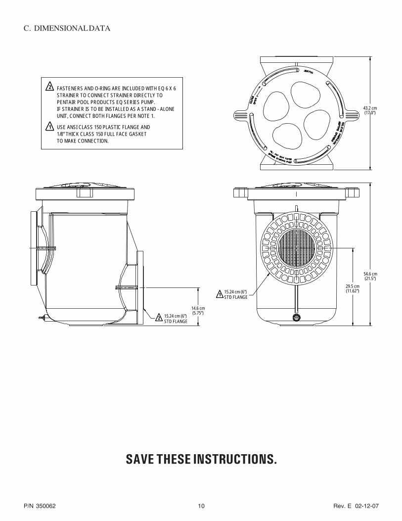
C. DIMENSIONAL DATA
FASTENERS AND O-RING ARE INCLUDED WITH EQ 6 X 6STRAINER TO CONNECT STRAINER DIRECTLY TOPENTAIR POOL PRODUCTS EQ SERIES PUMP.IF STRAINER IS TO BE INSTALLED AS A STAND - ALONEUNIT, CONNECT BOTH FLANGES PER NOTE 1.
USE ANSI CLASS 150 PLASTIC FLANGE AND1/8" THICK CLASS 150 FULL FACE GASKETTO MAKE CONNECTION.
2
1
115.24 cm (6")STD FLANGE
2 15.24 cm (6")STD FLANGE
14.6 cm(5.75")
43.2 cm(17.0")
54.6 cm(21.5")
29.5 cm(11.62")
SAVE THESE INSTRUCTIONS.
Rev. E 02-12-07 11 P/N 350062
Technical and Customer Support (Europe)For technical support questions and product service information, contact:
Phone: (0032) 14 25 99 66 - 8 A.M. to 5 P.M. (GMT)
Fax: (0032) 14 25 99 73
Technical and Customer Support (United States)
For technical support questions and product service information, contact:
Sanford, North Carolina (8 A.M. to 5 P.M. - EST)
Moorpark, California (8 A.M. to 5 P.M. - PST)
Phone: (800) 831-7133
Fax: (800) 284-4151
www.pentairpool.com and staritepool.com

P/N 350062 12 Rev. E 02-12-07
Pentair Water Pool and Spa, Inc.1620 Hawkins Ave., Sanford, NC 27330 • (919) 566-800010951 West Los Angeles Ave., Moorpark, CA 93021 • (800) 5000Visit us on the Internet at: www.pentairpool.com
SAVE THESE INSTRUCTIONS
© 2007 Pentair Water Pool and Spa, Inc. All rights reserved.
This document is subject to change without notice.
EQ Series and the Pentair Pool Products logo are registered trademarks of Pentair Water Pool and Spa, Inc. Other trademarks and trade names may be used in this documentto refer to either the entities claiming the marks and names or their products. Pentair Water Pool and Spa, Inc. disclaims any proprietary interest in trademarks and trade namesother than its own.